


BroilVection™
Model JF64-2 Flow Through
Natural Gas/LP
Owner’s Manual
APPROVALS:
F O R Y O U R S A F E T Y:
Do not store or use gasoline or other flammable vapors or liquids in the vicinity of this or any other appliance.
WA R N I N G :
Improper installation, adjustment, alteration, maintenance can cause property damage, injury, or death. Read the installation, operating and maintenance instructions thoroughly before installing or servicing this equipment.
Broiler area must be kept free of combustible materials, and the flow of combustion and ventilation air must not be obstructed. Operating personnel must not perform any maintenance or repair
functions. Contact your Nieco Authorized Dealer.
IMPORTANT: RETAIN THIS MANUAL IN A SAFE PLACE FOR FUTURE REFERENCE

Table of ConTenTs
a. General Information . . . . . . . . . . . . . . . . . . . . . . . . . . . . . . . . . . . . . . . . . . .4
A.1 Description . . . . . . . . . . . . . . . . . . . . . . . . . . . . . . . . . . . . . . . . . . . . .4
A.2 Warranty Information . . . . . . . . . . . . . . . . . . . . . . . . . . . . . . . . . . . . .4
A.3 Service/Technical Assistance . . . . . . . . . . . . . . . . . . . . . . . . . . . . . . .5
A.4 Safety Information . . . . . . . . . . . . . . . . . . . . . . . . . . . . . . . . . . . . . . .5
b. Machine Installation . . . . . . . . . . . . . . . . . . . . . . . . . . . . . . . . . . . . . . . . . . .7
B.1 Pre-Installation . . . . . . . . . . . . . . . . . . . . . . . . . . . . . . . . . . . . . . . . . .7
B.2 Mounting . . . . . . . . . . . . . . . . . . . . . . . . . . . . . . . . . . . . . . . . . . . . . .7
B.3 Leveling . . . . . . . . . . . . . . . . . . . . . . . . . . . . . . . . . . . . . . . . . . . . . . .7
B.4 Hood Requirements . . . . . . . . . . . . . . . . . . . . . . . . . . . . . . . . . . . . . .7
B.5 Clearance . . . . . . . . . . . . . . . . . . . . . . . . . . . . . . . . . . . . . . . . . . . . . .7
B.6 Gas Connection . . . . . . . . . . . . . . . . . . . . . . . . . . . . . . . . . . . . . . . . .8
B.7 Flexible Gas Line Installation . . . . . . . . . . . . . . . . . . . . . . . . . . . . . . .8
B.8 Restraining Device . . . . . . . . . . . . . . . . . . . . . . . . . . . . . . . . . . . . . . .9
B.9 Electrical Connection . . . . . . . . . . . . . . . . . . . . . . . . . . . . . . . . . . . . .9
B.10 Pre-Operation Check . . . . . . . . . . . . . . . . . . . . . . . . . . . . . . . . . . . . .9
C. operation . . . . . . . . . . . . . . . . . . . . . . . . . . . . . . . . . . . . . . . . . . . . . . . . . . .10
C.1 Controls and Indicators . . . . . . . . . . . . . . . . . . . . . . . . . . . . . . . . . .10 C.2 Step-by-Step Lighting Procedure . . . . . . . . . . . . . . . . . . . . . . . . . . .12 C.3 Shutdown Procedure . . . . . . . . . . . . . . . . . . . . . . . . . . . . . . . . . . . .13 C.4 Control Operation . . . . . . . . . . . . . . . . . . . . . . . . . . . . . . . . . . . . . . .14
D. assembly/Disassembly and Cleaning . . . . . . . . . . . . . . . . . . . . . . . . . . . .15 e. Troubleshooting Guide . . . . . . . . . . . . . . . . . . . . . . . . . . . . . . . . . . . . . . . .27 f. Parts location Drawings . . . . . . . . . . . . . . . . . . . . . . . . . . . . . . . . . . . . . .28 G. Wiring Diagram . . . . . . . . . . . . . . . . . . . . . . . . . . . . . . . . . . . . . . . . . . . . . .31 H. specifications . . . . . . . . . . . . . . . . . . . . . . . . . . . . . . . . . . . . . . . . . . . . . . .35
2Model JF64-2 GAS Flow Through

a. GeneRal InfoRMaTIon
a.1 Description
The Nieco® Model JF63 (single belt) and JF63-2 (dual belt) automatic broiler features high release convection burners, Patent pending BroilVection™ air system that uses waste heat to greatly reduce energy needs, easy cleaning and a simple and intuitive control package to help eliminate broiling problems and provide the operator with even greater control over the broiling environment.
This manual provides the safety, installation and operating procedures for the Nieco Automatic Broiler Model JF63. We recommend that all information
contained in this manual be read prior to installing and operating the broiler. a.2 Warranty Information
Please read the full text of the limited Warranty in this manual.
If the unit arrives damaged, contact the carrier immediately and file a damage claim with them. Save all packing materials when filing a claim. Freight damage claims are the responsibility of the purchaser and aRe noT covered under warranty.
The warranty does not extend to:
•Damages caused in shipment or damage as a result of improper use.
•Installation of electrical service.
•Normal maintenance as outlined in this manual.
•Malfunction resulting from improper maintenance not in accordance with the steps contained in this manual and any applicable training.
•Damage caused by abuse or careless handling outside of the normal operating procedures contained in this manual.
•Damage from moisture into electrical components.
•Damage from tampering with or removal of any safety device.
IMPoRTanT!
Keep these instructions for future reference. If the unit changes ownership, be sure this manual accompanies the equipment.
IMPoRTanT
The nieco Corporation reserves the right to change specifications and product design. such revisions do not entitle the buyer to corresponding changes, improvements,
additions or replacements for previously purchased equipment.
3 |
Model JF64-2 GAS Flow Through |
a.3 service/Technical assistance
If you experience any problems with the installation or operation of your broiler, contact your local Authorized Nieco Distributor.
Fill in the information bellow and have it handy when calling your authorized service agency for assistance. The serial number is on the broiler rating plate on the side of the unit.
Purchased from: Date of Purchase: Model No.:
Serial No.:
For the name of your local Authorized Nieco Distributor, please call (800) 821-2141.
Use only genuine Nieco replacement parts in your broiler. Use of replacement parts other than those supplied by Authorized Nieco Distributors and Service Agencies will void the warranty and may significantly alter the performance of your broiler. The use of non-Nieco parts is capable of affecting these criteria, and may affect broiler performance, parts longevity and food safety. Your local Authorized Nieco Distributor and Service Agent has been factory trained and has a complete supply of parts for your Nieco Automatic Broiler.
You may contact the factory direct at (707) 284-7100 if you have trouble locating your local Nieco Distributor.
a.4 Important safety Information
Throughout this manual, you will find the following safety words and symbols that signify important safety issues with regards to operating or maintaining the equipment:
WaRnInG 
GeneRal WaRnInG. Indicates information important to the proper operation of the equipment. failure to observe may result in damage to the equipment and/or severe bodily injury or death.
CaUTIon 
GeneRal CaUTIon. Indicates information important to the proper operation of the equipment. failure to observe may result in damage to the equipment.
WaRnInG
eleCTRICal WaRnInG. Indicates information relating to possible shock hazard. failure to observe may result in damage to the equipment and/or severe bodily injury or death.
WaRnInG
HoT sURfaCe WaRnInG. Indicates information important to the handling of equipment and parts. failure to observe caution could result in personal injury.
4Model JF64-2 GAS Flow Through

a.4 Important safety Information (Continued.)
In addition to the warnings and cautions in this manual, use the following guidelines for safe operation of your Nieco Automatic Broiler:
•Read and follow all instructions before using this equipment.
•Install or locate broiler only for its intended use as described in this manual.
•Do not operate this equipment if it has a damaged cord or plug, if it is not working properly or if it has been otherwise damaged.
•This equipment should only be serviced by authorized personnel. Contact your local Nieco Distributor for adjustment or repair.
•Use only genuine Nieco replacement parts for your broiler. Failure to do so will void the warranty and may significantly alter the performance of your broiler. The use of non-Nieco parts is capable of affecting these criteria, and may affect broiler performance, parts longevity and food safety.
The following warnings and cautions appear throughout the manual and should be carefully observed:
•Turn the broiler off, close the main gas valve, and disconnect the plug before performing any service, maintenance or cleaning on the broiler.
•always allow the broiler to fully cool before performing any service, maintenance or cleaning. failure to wait for the broiler to cool fully may result in personal injury.
•The procedures in this manual may include reference to the use of chemical products. The nieco Corporation does not endorse the use of any particular cleaning/degreasing agent. Use only those chemicals that are approved for use in your kitchen.
•The broiler should be grounded according to local electrical codes to prevent the possibility of electrical shock. It requires a grounded receptacle with separate electrical lines, protected by fuses or circuit breakers of the proper rating.
•all electrical connections must be in accordance with local electrical codes and any other applicable codes.
•The use of adequate ventilation (as rated in this manual) with this broiler is mandatory. failure to adequately ventilate this unit and provide safe operating distances (as specified in this manual) is a fire safety hazard. follow the instructions for emergency broiler shutdown in the event of an emergency.
•no attempt should be made to operate this appliance in the event of a power failure.
WaRnInG eleCTRICal sHoCK HaZaRD. faIlURe To folloW THese InsTRUCTIons CoUlD |
||
ResUlT In seRIoUs InJURY oR DeaTH: |
||
_ |
electrical ground is required on this appliance. |
|
_ |
||
Check with a qualified electrician if you are in doubt as to whether the appliance is properly |
||
_ |
grounded. |
|
Do not use water on or near the control box for risk of serious injury or death due to |
||
|
electrical shock. |
|
WaRnInG, HIGH TeMPeRaTURes WITH HoT sURfaCes. faIlURe To folloW THese PRoCeDURes CoUlD ResUlT In seRIoUs InJURY:
_Do not attempt to clean, disassemble or perform maintenance on this broiler until it is fully cooled as per the instructions contained in this manual.
5 |
Model JF64-2 GAS Flow Through |

b.1 Pre-Installation
Uncrate the broiler and inspect for shipping damage. Remove the tape securing the machine parts, and install the parts in their proper location. If there are obvious or concealed damages to any part of the broiler, please contact your freight carrier. The factory warranty does not cover freight damage.
b.2 Mounting
Follow the mounting instructions if this function is not performed by the installer. b.3 leveling
The grease drain system is based on a gravity-flow design. Therefore, it is extremely important that the broiler be placed on a level surface.
b.4 Hood Requirements
This appliance must be installed under a ventilation hood of adequate size. Do not obstruct the flow of combustion and ventilation air. An adequate air supply must be available for safe and proper operation.
For installations in the Commonwealth of Massachusetts the following shall apply: Venting shall be in compliance with NFPA Section 10.3.5.2 for the Model MPB94.
b.5 Clearance
Keep appliance area free from combustibles.
To facilitate disassembly and service of the unit a minimum of 24” (610 mm) should be allowed on the control panel (feed end) of the broiler.
ReQUIReD anD ReCoMMenDeD CleaRanCes |
|
|||
|
|
|
|
|
|
ReQUIReD for |
ReQUIReD for installa- |
ReCoMMenDeD by |
|
|
installation near |
tion near non-com- |
Nieco for proper disas- |
|
|
combustible walls |
bustible walls and |
sembly and service |
|
|
and construction |
construction |
|
|
|
|
|
|
|
Back of broiler |
12” (305 mm) |
0” (0 mm) |
0” (0 mm) |
|
|
|
|
|
|
Sides of broiler |
12” (305 mm) |
0” (0 mm) |
0” (0 mm) |
|
|
|
|
|
|
Front of broiler |
12” (305 mm) |
0” (0 mm) |
24” (610 mm) |
|
(Feed end) |
||||
|
|
|
||
|
|
|
|
|
6 |
Model JF64-2 GAS Flow Through |

b.6 Gas Connection- 3/4” n.P.T.
At rated input the gas supply should deliver a minimum pressure of at least 15 mbar (6" water column) at the broiler connection for natural gas. Incoming gas supply pressure must not exceed 50 mbar (14" water column).
note: The installation of this appliance must conform with local codes, or in the absence of local codes, with the National Fuel Gas Code, ANSI Z223.1, Natural Gas Installation Code, CAN/CGA-B149.1 including:
1.The appliance and its individual shutoff valve must be disconnected from the gas supply piping system during any pressure testing of that system at test pressures in excess of 1/2 psi (3.45 kPa).
2.The appliance must be isolated from the gas supply piping system by closing its individual manual shutoff valve during any pressure testing of the gas supply piping system at test pressures equal to or less than 1/2 psi (3.45 kPa).
By public initiative, the State of California has adopted legislation (Proposition 65) which requires manufacturers of many types of products, including gas appliances, to warn consumers of their products that contain chemicals or produce substances listed by the State of California to either cause cancer, birth defects or other reproductive harm.
WaRnInG
If not installed, operated and maintained in accordance with the manufacturers instructions, this product could expose you to substances in fuel or from fuel combustion which can cause cancer, birth defects or other reproductive harm.
b.7 Installing Gas appliance Connectors and flexible Gas lines Correctly
For safety in the kitchen area, and to insure maximum service life, it is vitally important to correctly install connectors. The connector shall comply with the Standard for Connectors for Moveable Gas Appliances, ANSI Z21.69 or CAN/CGA-6.16 and a quick disconnect device that complies with the Standard for QuickDisconnect Devices for use with gas fuel, ANSI Z21.41 or CAN1-6.9
In order to avoid sharp kinks or excessive bends that could have a damaging effect on the connector, it may be necessary to attach pipe elbows in order to bring the connector into its proper plane. For easy movement of the appliance, the connector should be installed with a "lazy" loop for minimum tension.
note: Gas appliances should be disconnected prior to maximum movement. (Minimal movement is possible to connect hose.)
7 |
Model JF64-2 GAS Flow Through |
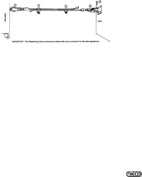
b.8 Restraining Device Installation and Use
This high strength restrainer is to be used with all moveable (castered) appliances. It fully complies with American Gas Association requirements. References: Z21.69, Z83.11, and Z21.41 with current revisions. Installation is quick and positive. In Canada, device is in accordance with CAN 1-6.9-M70 Quick Disconnect Devices for use with gas fuel, and CAN 1-6.10-88 metal connectors for gas appliances. Correct length for any appliance is simply a matter of loosening two adjuster clips (1) and re-tightening. (3" to 6" shorter than appliance connector is desired length.) Restrainer is made of heavy duty steel cable, with a strong scissor hood (2) at one end, and an equally strong spring hook (3) at the other. Cotter pin (4) is supplied to secure the installation. For proper attachment to the broiler, use the supplied hardware to attach the device to the holes in the shear plate of the broiler stand.
noTe: If disconnection of the restraint is necessary, reconnect the restraint after the appliance has been returned to its originally installed position.
b.9 electrical Connection
Power requirements are stated on the unit nameplate and must be connected accordingly. This appliance, when installed must be electrically grounded in accordance with local codes, or in the absence of local codes, with the National Electrical Code, ANSI/NFPA 70, or the Canadian Electrical Code, CSA C22.2, as applicable. Before starting broiler, tighten all electrical connections in control box. An electrical wiring diagram can be found inside the control box.
note: Disconnect power before servicing. b.10 Pre-operation Check
Be sure that all parts are installed in the proper location:
Ventilation is turned on Broiler is plugged in Gas line is connected
8 |
Model JF64-2 GAS Flow Through |

|
C. oPeRaTIon |
|
C.1 |
Controls and Indicators |
|
1.Belt Speed Control - Used to set the broil time for the |
1. |
|
meat belt NOTE: The JF63-2 is equipped with two (2) |
|
|
speed controls). |
|
|
2.Load Sensing Control - Used to help stabilize the broiler under load.
3.Main On/Off Switch - Turns the broiler on and off.
4.Ignition Failure Light - If flashing, indicates the broiler is no longer lit.
5.Power Indicator Light - Glows green when the power to the broiler is on.
2.
3.
4
5
10 |
Model JF64-2 GAS Flow Through |

C. oPeRaTIon
C.1 Controls and Indicators
6. Multi Product Control (P/N 15161-B) - Used to broil a variety of products that may require different settings (If equipped)
MUlTI-PRoDUCT ConTRol (If equipped)
1. |
LED DISPLAY - Shows current product selection |
|
|
|
and cook time. |
(1) |
|
2. |
PRODUCT SELECTION BUTTONS - Press to |
||
|
|||
|
select different presets for different products. |
|
|
3. |
ADJUSTMENT BUTTONS - Use to adjust product |
|
|
|
cook times, element settings and product names. |
|
|
4. |
SELECTION INDICATOR LIGHT - Lights up to |
|
|
|
show which button is selected. |
|
|
|
|
(2) |
on THe baCK of THe bRoIleR |
|
|
|
a. Belt Reverse Buttons - In the event the broiler gets |
|
|
|
|
|
a |
|
jammed, use these buttons to reverse the direction of the |
a |
|
|
meat belt to help clear the jam. |
|
|
|
|
|
|
10 |
Model JF64-2 GAS Flow Through |
C.2 lighting Procedures
PRe-lIGHTInG PRePaRaTIon
1. Broiler is |
2. Gas valve is |
3. Turn ventilation |
centered under |
open when |
system on |
hood and |
handle is in line |
|
plugged in |
(parallel to) the |
|
|
pipe |
|
noRMal IGnITIon
WaRnInG 
THe VenTIlaTIon sYsTeM MUsT be on aT all TIMes DURInG bRoIleR oPeRaTIon. oPeRaTInG bRoIleR WITHoUT PRoPeR VenTIlaTIon Is a seVeRe fIRe HaZaRD.
The JF63 is equipped with automatic ignition. When the broiler is turned on, a hot surface ignitor turns on 5 seconds |
|
before the flow of gas. Gas then flows to all of the burners. If the burners are not lit within 10 seconds, the control will |
|
reset and try again for 10 seconds. This occurs 3 times. If the broiler does not light after the third attempt, the ignition |
|
failure light will flash and the main on/off switch must be cycled to repeat the procedure. If this still doesn’t light the |
|
broiler, see the MANUAL IGNITION instructions. |
|
1. Turn the MaIn PoWeR sWITCH on. |
1. |
2. Allow broiler to heat for 45 minutes before cooking. |
2. |
11 |
Model JF64-2 GAS Flow Through |
 Loading...