

Page 1

AUTOMATIC
FOODSERVICE
EQUIPMENT
AUTOMATIC ELECTRIC BROILER
MODELS 952E, 932E and 922E
OWNER’S MANUAL
IMPORTANT: RETAIN THIS MANUAL IN A SAFE PLACE FOR FUTURE REFERENCE.
Broiler area must be kept free of combustible materials, and the flow of combustion and ventilation air must not
be obstructed. Operating personnel must not perform any maintenance or repair functions. Contact your Nieco
Authorized Dealer.
FOR YOUR SAFETY:
Do not store or use gasoline or other flammable vapors or
liquids in the vicinity of this or any other appliance.
Page 2

2
Page 3

3
TABLE OF CONTENTS
A. Machine Installation.....................................................................................................................4
Pre-Installation
Mounting
Hood Requirements
Clearance
Electrical Connection
Pre-Operation Check
B. Operation......................................................................................................................................5
Controls and Indicators
Broil Temperature Stabilizer Control
Step-by-Step Starting Procedure
Shutdown Procedure
C. Parts and Location.......................................................................................................................8
952
932
922
D. Cleaning........................................................................................................................................17
E. Periodic Maintenance ..................................................................................................................17
F. Conveyor Belt Removal
...............................................................................................................18
G. Conveyor Belt Tension................................................................................................................19
Broil Belt Problems
H. Trouble Shooting Guide..............................................................................................................20
I. Wiring Diagrams
..........................................................................................................................22
Page 4

4
A. INSTALLATION
PRE-INSTALLATION
Uncrate the broiler, and inspect for shipping damage. Contact the factory if there is obvious damage. Remove
the tape securing the machine parts, and install the parts in their proper location. Refer to the Parts and
Location section of this manual. If you find concealed damage to any part of this unit, contact your freight carrier immediately. The factory warranty does not cover freight damage.
MOUNTING
If the broiler was shipped with a tubular stand, refer to seperate tubular stand assembly instructions.
Note: The four legs of the broiler stand are equipped with casters. Always set the brakes on the casters to prevent the broiler from shifting during operation or cleaning.
HOOD REQUIREMENTS
This appliance must be installed under a ventilation hood of adequate size and capacity (approximately 600
CFM). The hood should be at least 6" larger in all dimensions than the appliance top, and be 12" to 18" above
the top. Do not obstruct the flow of combustion and ventilation air. An adequate air supply must be available
for safe and proper operation.
Note: See the National Fire Prevention Association booklet on ventilation of cooking equipment. Write
to: NFPA, 470 Atlantic Ave., Boston, MA 02210. Local codes on venting must also be complied with.
CLEARANCE
For proper installation, the minimum clearance from combustible and non-combustible construction is 6" from
the back and 6" from the front of the machine. Keep appliance area free from combustibles.
To facilitate disassembly and service of the unit a minimum of 24" should be allowed on the control panel
(right) side of the broiler, as well as in front of the broiler.
ELECTRICAL CONNECTION
Power requirements are stated on the unit nameplate and must be connected accordingly. Before starting
broiler, tighten all electrical connections in control box.
Note: This appliance must be electrically grounded in accordance with local codes or in the absence
of local codes, the National Electrical Code, ANSI/NFPA No. 70-1990. In Canada, in accordance with
the Canadian Electrical Code CSA 22.1 part 1, or local codes.
WARNING: This appliance should be connected with a five-pronged grounding plug for your
protection against shock hazard. Be sure to plug directly into a properly grounded five-prong
receptacle. Do not cut or remove grounding prong from plug.
Note:
This appliance cannot be safely operated in the event of a power failure. No attempt should be
made to operate during a power failure. Disconnect power supply before servicing.
PRE-OPERATION CHECK
Be sure that all parts are installed in the proper location. Refer to OPERATION section for lighting procedure.
Start broiler and test for proper operation.
Page 5
5
B. OPERATION
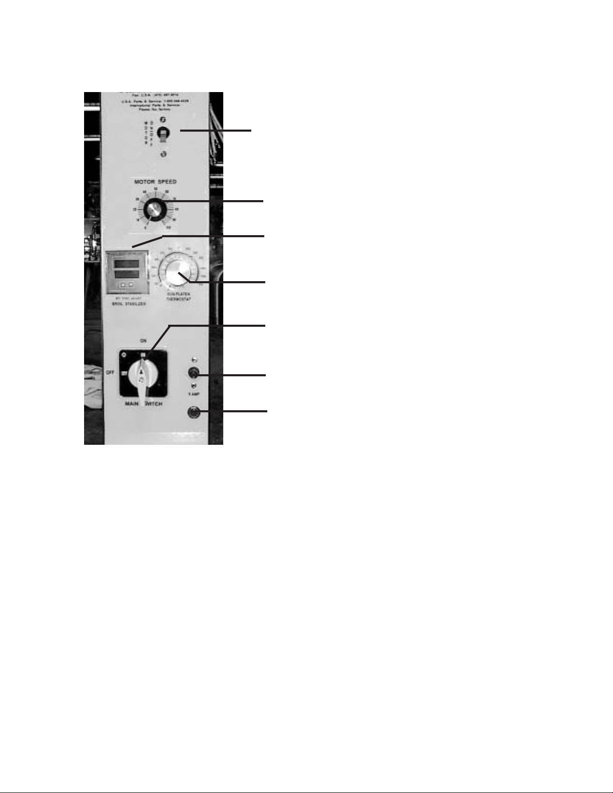
CONTROLS AND INDICATORS
(Note: Controls for the 922E are in a slightly different position)
Motor Breaker Switch
Motor Speed Control - adjusts the speed of the conveyor belt.
Broil Temperature Stabilizer Control:
Top Number = Actual Temperature
Bottom Number = Set Temperature
Meat Holding Unit Temperature Control. (Use a setting of 200°
F to start)
Main Power Switch
Fuse - 5 amp
Power on indicator light.
After the hamburgers are cooked, they drop into the Holding Unit, which uses an electrically heated base to
maintain a set temperature for holding the hamburgers or chicken.
Page 6

6
BROIL TEMPERATURE STABILIZER CONTROL
The Models 952, 932E & 922E are equipped with a Broil Temperature Stabilizer Control that
senses when the broiler is being used, and adjusts the temperature to keep the broiler hot during heavy use. The control consists of two parts - a temperature probe to sense the internal
temperature of the broiler, and the control itself.
CALIBRATING THE BROIL STABILIZER CONTROL
In order to assure proper operation, the Broil Stabilizer Control must be calibrated for operation
in the restaurant. Every broiler will calibrate slightly differently, depending on supply voltage,
ventilation, etc. Follow these step by step instructions when the broiler is new, and once per
month after.
Step 1: Be sure all pieces of the broiler are in place. Make sure the broiler is plugged in and
the exhaust hood is turned on. Turn the broiler on by turning the main power switch to
the right. Turn on the conveyor belts using the motor breaker switch.
Step 2: Set the temperature (bottom number) to 200° F. Use the up or down arrows on the con-
trol to set the temperature. The bottom number is the set temperature and the top number is the actual temperature.
Step 3: Allow the broiler to heat up for 40 minutes. During this time, the actual temperature will
climb. Wait until the actual temperature stabilizes before proceeding.
Step 4: Set the ATC (bottom number) to 200° F higher than the actual temperature. For exam-
ple, if the broiler stabilizes at 700° F, then the proper setting should be 900° F.
WARNING
The broiler can be damaged if this control is not set according to instructions.
TROUBLE SHOOTING ERROR MESSAGES
Message Action
ER 4 Turn power on and off several times. If the message remains, replace control. If
the message disappears, the control may need to be reprogrammed. Call Nieco
or your local distributor for instructions.
ER 6 Cycle power on and off several times. If message remains, replace temperature
probe (P/N 4073).
Page 7
7
Before starting broiler, ensure that all parts are installed in the proper location, and the ventilation hood is turned on.
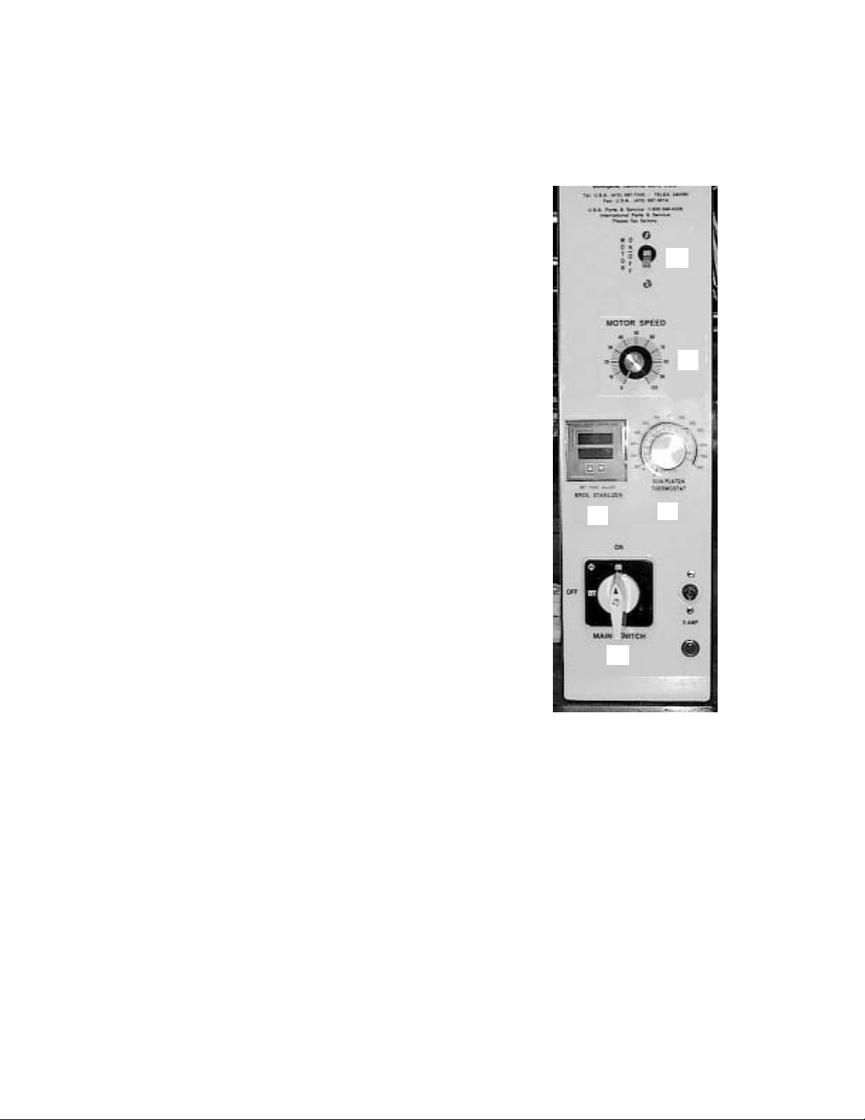
STEP-BY-STEP STARTING PROCEDURE
1. Turn on Main Power by turning the Main
Power Switch (A) to the right.
2. Turn on Motor Power Switch (B) and set
Motor Speed Control (C) to desired setting. (Use a setting of “50” to start.)
3. Check the Broil Temperature Stabilizer
(D). Daily setting should not be necessary.
Top Number = Actual Temperature
Bottom Number = Set Temperature
4. Set the temperature on the holding section (E). Use a setting of 200° F to start.
Recommended maximum holding time is 10
minutes.
SHUTDOWN PROCEDURE
For EMERGENCY Shutdown, turn the Main Power Switch off. Rotate the switch to the left.
For planned shutdowns, perform the following procedure:
1. Clear machine of all food products.
2. Turn Main Power Switch off.
3. Turn Motor Switch off.
CAUTION: Always turn machine completely off before unplugging power cord.
CAUTION: Allow machine to cool before removing any parts.
A
B
C
D
E
Page 8
8
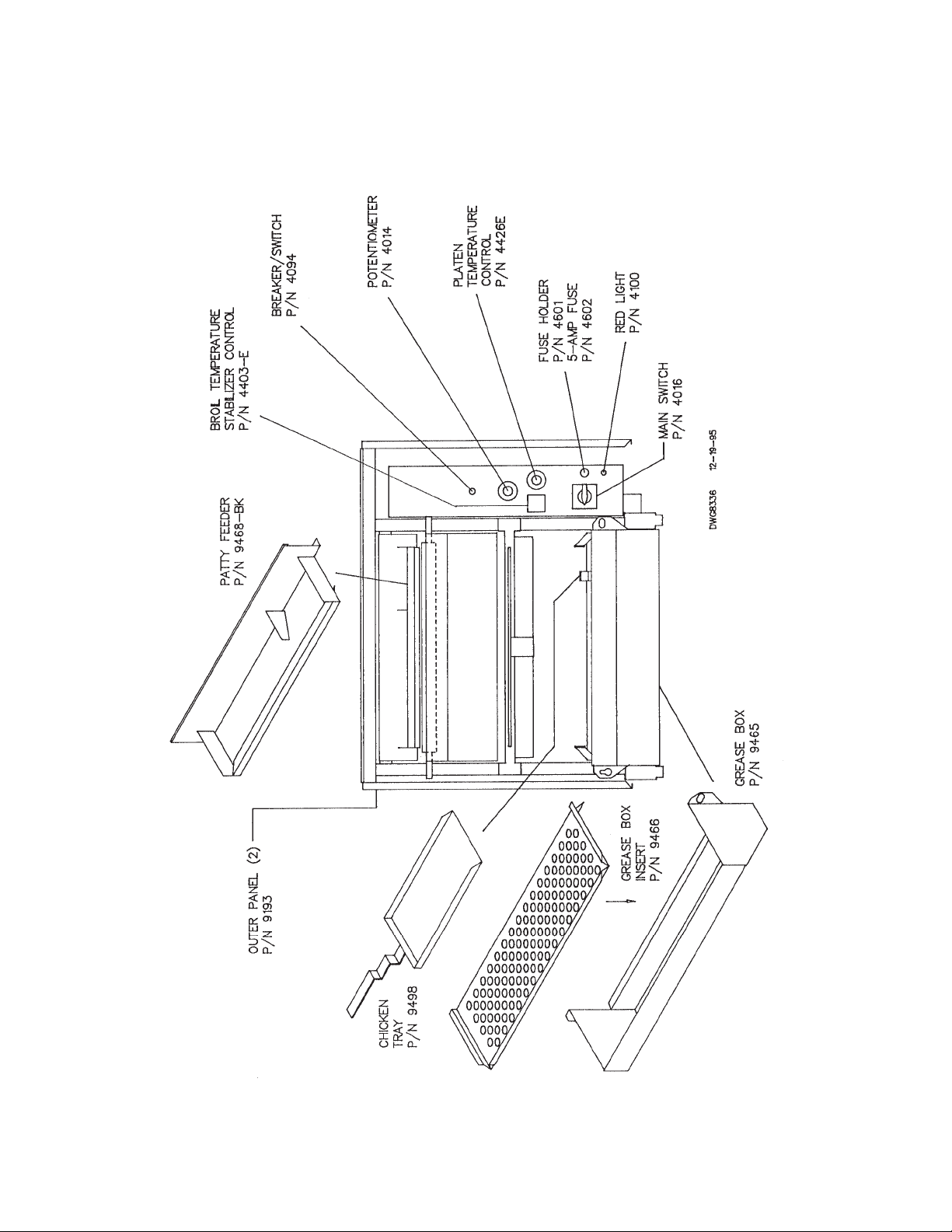
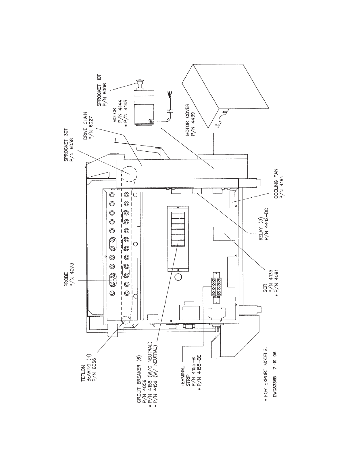
C. PARTS AND LOCATION
Model 952 Electric - Feed End View
Page 9
9
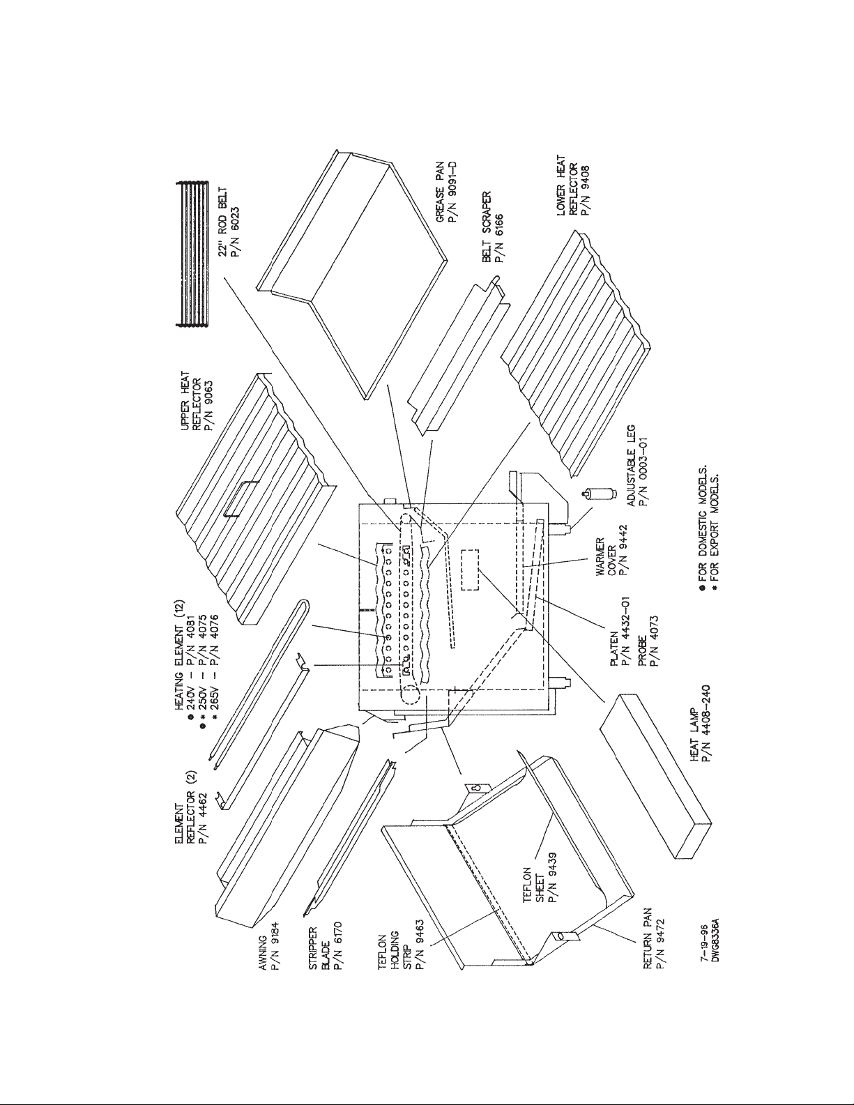
C. PARTS AND LOCATION
Model 952 Electric - Left Side View
Page 10
10
C. PARTS AND LOCATION
Model 952 Electric - Right Side View
Page 11

11
C. PARTS AND LOCATION
Model 932 Electric - Feed End View
Page 12
12
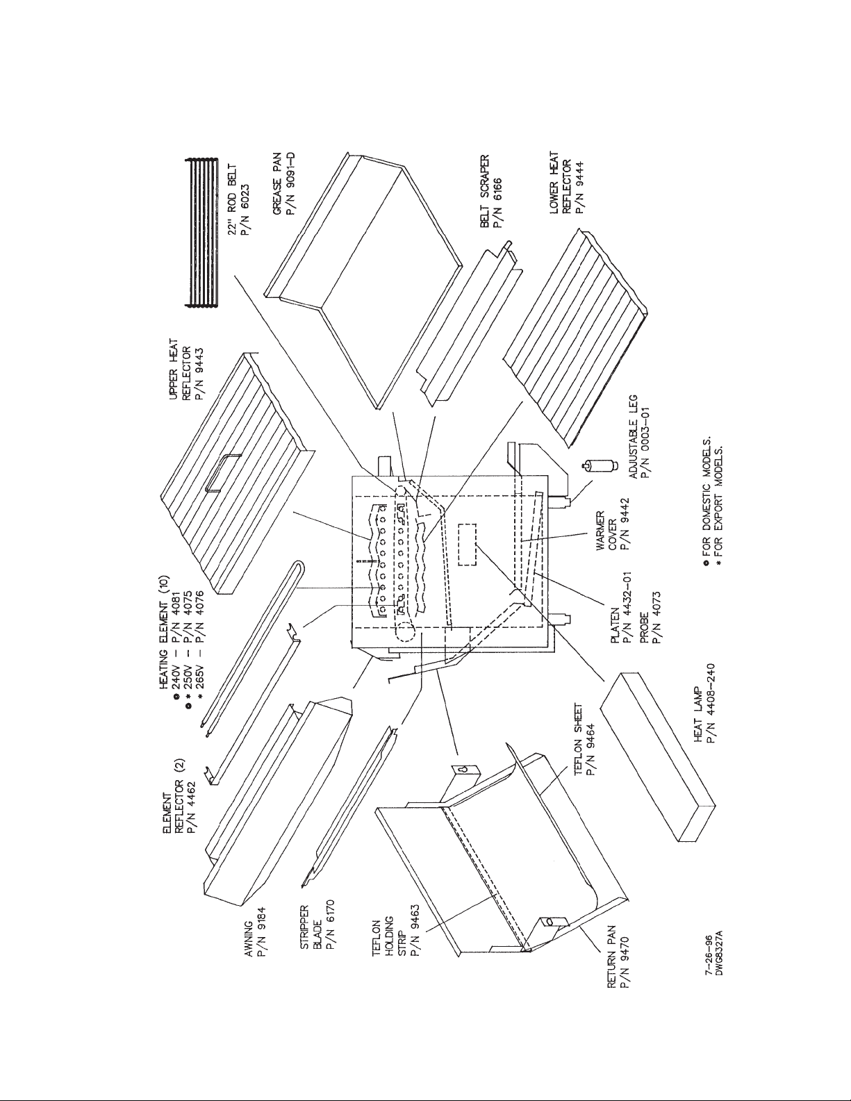
PARTS AND LOCATION
Model 932 Electric - Left Side View
Page 13
13
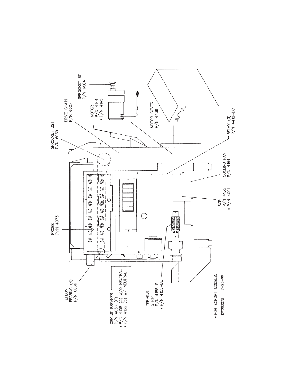
PARTS AND LOCATION
Model 932 Electric - Right Side View
Page 14
14
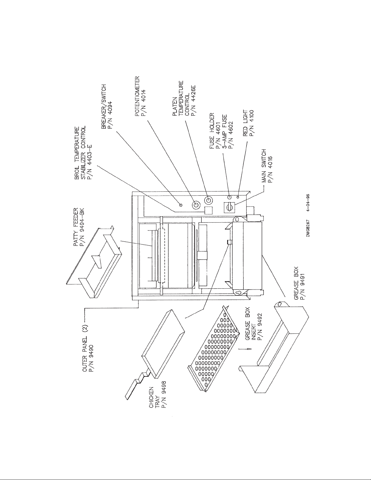
PARTS AND LOCATION
Model 922 Electric - Feed End View
Page 15
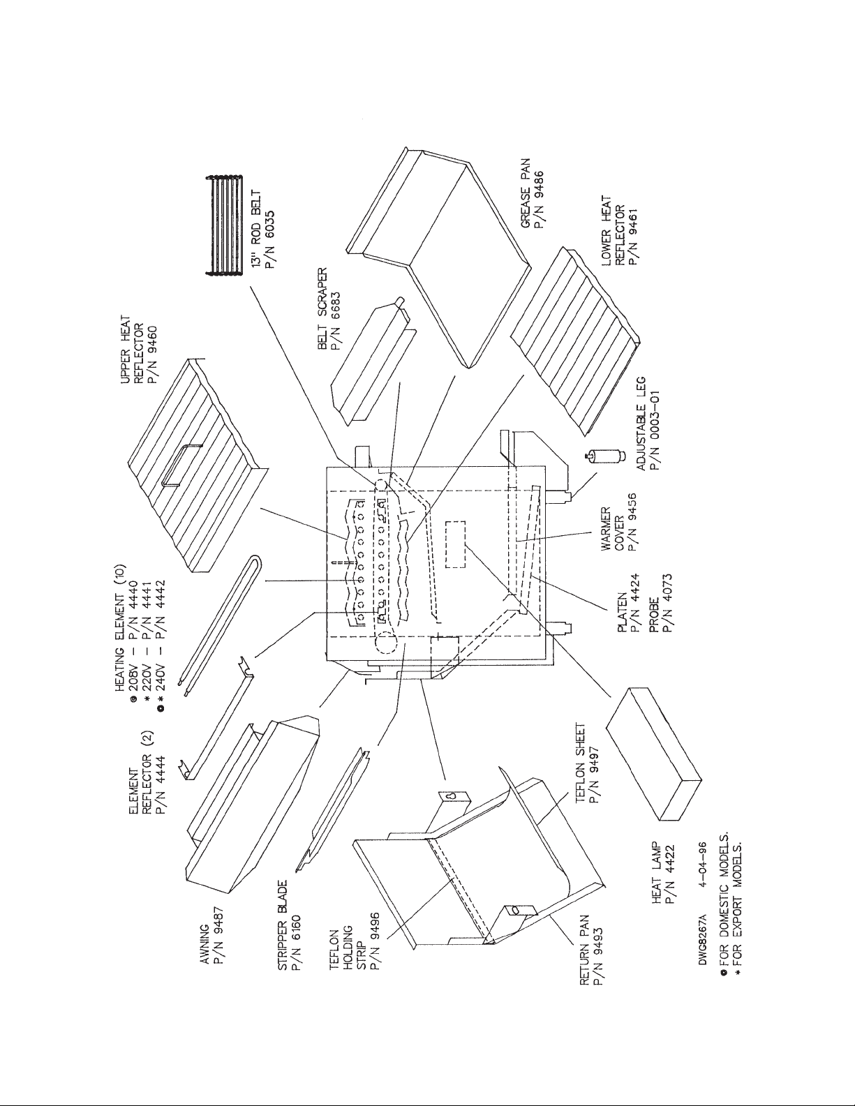
15
PARTS AND LOCATION
Model 922 Electric - Left Side View
Page 16
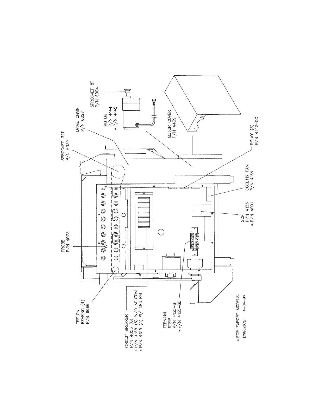
16
PARTS AND LOCATION
Model 922 Electric - Right Side View
Page 17

17
D. CLEANING INSTRUCTIONS
DAILY CLEANING
Clear broiler of all food product before shutting down to clean. Allow broiler to cool before handling parts.
1. SHEET METAL PARTS. Remove all trays, drip pans, stripper blades, reflectors, and side panels.
Wash with water and an approved degreaser detergent.
2. SHAFTS. Clean the drive shafts with the special tool provided.
3. MEAT HOLDING PLATEN. Clean and sanitize the meat holding platen daily, including the teflon sheet.
WEEKLY CLEANING
1. Clean the frame of the broiler as necessary to remove grease build up.
E. PERIODIC MAINTENANCE
Note: Maintenance should be performed by authorized personnel only. Always disconnect the power
before performing any maintenance on the broiler.
Check the heating elements periodically for signs of wear. Rotating the top and bottom elements every 6 months
will increase the life of the elements, and improve the performance of the broiler.
The motor uses carbon brushes that will eventually wear out. Replace the brushes if there is excessive noise or
erratic performance from the motor.
Page 18
18
F. CONVEYOR BELT REMOVAL
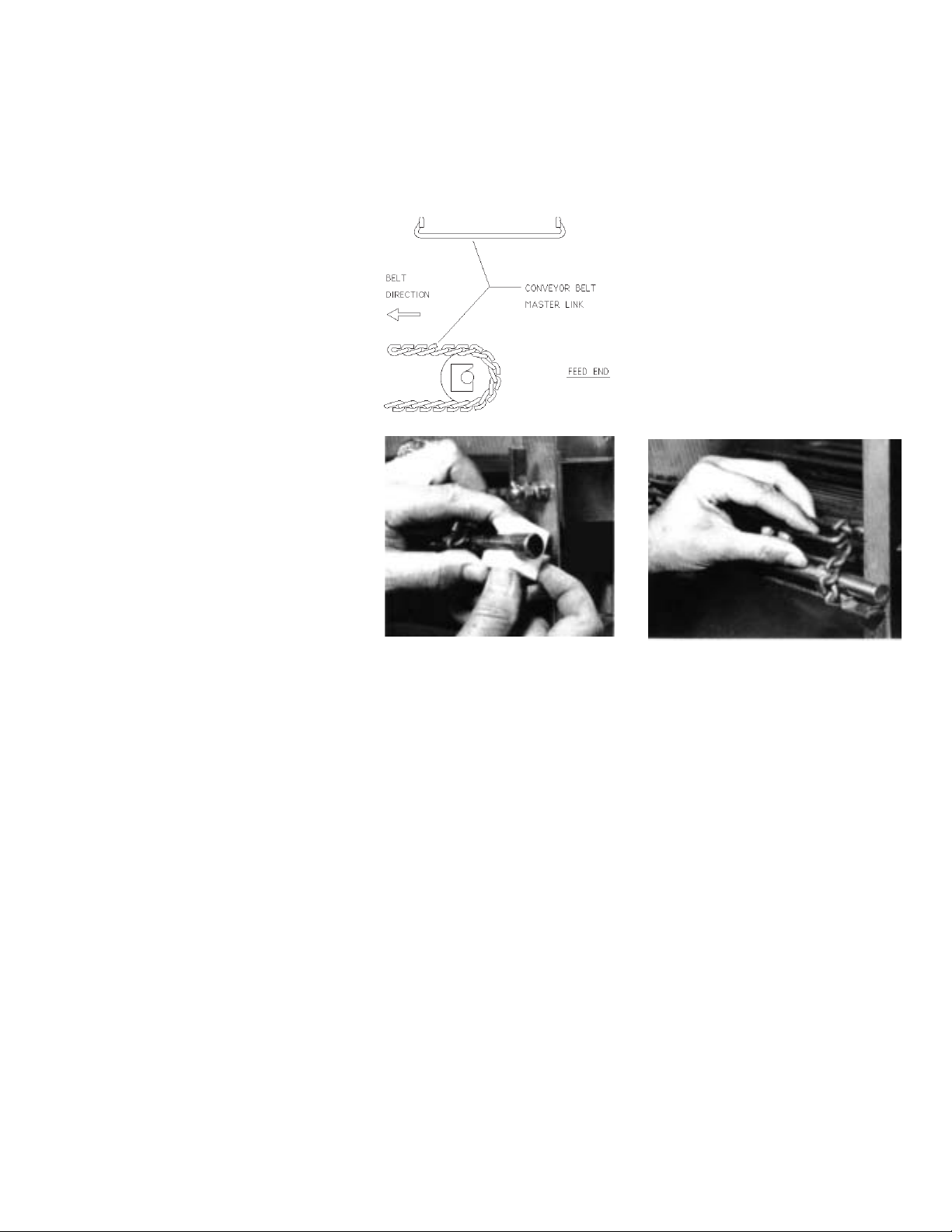
Before beginning, notice the way the belt runs through the broiler. Also notice the direction the knuckles face. Be sure
to re-assemble in the same way.
1. Run belt until the Master Link is 1
near the front idler shaft.
2. Lift shaft and Teflon Blocks up, 2 3
and slide the blocks out.
3. Unhook the Master Link.
To reassemble, reverse the procedure. Be sure to reassemble the belt with the knuckle opening facing away from the
direction of travel.
Page 19
19
G. CONVEYOR BELT TENSION
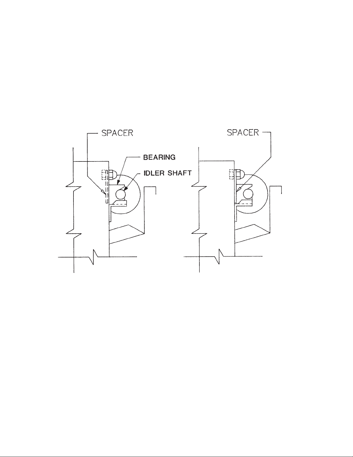
Maintain proper tension on the conveyor belts to prevent jamming. Bearing spacers (pictured below) are
supplied with the broiler to make minor tension adjustments. Major tension adjustments are made by
removing a link or links from the belt.
The diagram on the left shows the spacer in the stored position. The diagram on the right shows the
spacer behind the teflon bearing tightening the belts.
Belt tension should be checked monthly. To do this, allow the machine to cool, then grip the idler shaft at
each end and pull on it. If the shaft and bearings move 3/16” or more, the spacers should be placed
behind the bearings to tighten the belts. If the spacers are already behind the bearings, return them to
the stored position and remove a link from the conveyor belt.
BROIL BELT PROBLEMS
Interference with stripper blade:
The most common belt problem to be expected is the physical interference of the belt with the stripper
blade. This is caused by bent or warped rods on the meat belt, and can be fixed by replacing the rods
that are causing the problem. Other causes are bent stripper blades, or utensils jammed in the belt.
Blocked belts:
When trouble shooting drive problems, it is important to ensure that the belt is not being blocked. To do
this, detach the drive chain and turn the meat belt by hand. The belt, with the motor detached, should
turn freely and easily. If the blockage has occurred which is preventing the belt from turning, the blockage should be removed before the drive chain is re-attached. The drive chain can be easily removed
from the drive sprocket (on the motor shaft) by loosening the mounting bolts and raising the motor.
Page 20

20
H. TROUBLE SHOOTING GUIDE
Identify the problem in the left column, and look for probable causes and solutions in the right hand columns. Probable
causes are listed in “most likely to happen” order. This sequence should be used to isolate the problem. Once the cause
is found, refer to OPERATION and PARTS AND LOCATION sections for explanation of function or repair part needed.
Wiring diagram is located inside electrical control box cover.
PROBLEM PROBABLE CAUSE SOLUTION
1. All elements go out or fail
to heat up.
2. Some elements are on,
but others refuse to heat.
3. Elements appear hotter or
colder than usual.
4. Meat Holding Platen won’t
heat.
5. Conveyor belts won’t
advance.
6. Motor control switch
trips.
1. Unit not plugged in properly.
2. Breaker switch on wall panel tripped.
3. Broiler circuit breakers tripped.
4. Broiler on/off switch defective.
5. Main contactor not closing.
6. Main contactor not staying closed.
1. Defective element.
2. Circuit breaker tripped.
3. Loose or broken wire.
1. Supply voltage is different than the element ratings.
1. Unit not plugged in properly.
2. Wall cicuit breaker tripped.
3. Defective thermostat/temperature controller.
4. Loose or broken wire.
5. Temperature set too low.
1. Conveyor belt jammed.
2. Machine not plugged in properly.
3. Wall circuit breaker tripped.
4. Motor control switch off.
5. Motor speed dial turned to zero.
6. SCR unplugged or defective.
7. Drive chain broken.
8. Drive sprocket loose.
9. Gear motor defective.
10. Speed pot defective.
11. Loose or broken wire.
12. Motor unplugged.
1. Conveyor chains jammed.
2. SCR defective.
3. Motor brushes worn out.
4. Drive chain binding.
5. Shorted wire to motor.
6. Motor defective.
7. Switch defective.
1. Plug in properly.
2. Reset circuit breaker.
3. Reset circuit breaker.
4. Replace.
5. Replace contactor coil.
6. Replace on/off switch and check for
loose wires.
1. Replace.
2. Reset.
3. Check all wires. Tighten or replace.
1. Correct supply voltage or install elements that are rated for the supply voltage.
1. Plug in properly.
2. Reset circuit breaker.
3. Replace.
4. Check all wires. Tighten or replace.
5. Increase setting on digital display.
1. Remove jam. Reset motor switch.
2. Plug in properly.
3. Reset circuit breaker.
4. Turn on.
5. Increase setting.
6. Plug in or replace.
7. Repair or replace.
8 Tighten set screw on the sprocket.
9. Replace.
10. Replace.
11. Check all wires. Tighten or replace.
12. Plug in. Check for grease or dirt in the
socket.
1. Remove jam. Reset motor switch.
2. Replace.
3. Replace.
4. Adjust chain tension. Lubricate.
5. Repair wire.
6. Replace.
7. Replace.
Page 21

21
PROBLEM PROBABLE CAUSE SOLUTION
7. Conveyor speeds are
erratic.
8. Broiled product over or
under cooked.
9. Broiled product sticks to
conveyor belt.
10. Inconsistent broil.
11. Broiler frame or parts
warping.
1. SCR loose or defective.
2. Speed control pot defective.
3. Drive chain binding.
4. Gear motor defective.
5. Loose drive sprockets.
1. Wrong conveyor belt speed.
2. Incorrect elements installed.
1. Stripper blades not adjusted or installed
properly.
2. Product under broiled.
3. Elements too cool.
4. Heat reflectors not installed or installed
improperly.
1. Conveyor speed erratic.
2. Incoming product temperature erratic.
3. Air condition vent blowing on broiler.
4. Erratic voltage supply.
5. Supply voltage incorrect.
6. Automatic Temperature Control failure.
1. Elements too hot.
1. Plug in or replace.
2. Replace.
3. Adjust chain tension. Lubricate.
4. Replace.
5. Tighten set screws on sprocket.
1. Adjust motor speed.
2. Match the voltage rating of the elements
to the supply voltage.
1. Adjust or install properly.
2. Decrease motor speed.
3. Check elements.
4. Refer to Parts & Location section for
proper placement of reflectors.
1. See #7 above.
2. Check freezers for proper operation.
3. Redirect air away from broiler.
4. Check supply. Contact electric company
if there are problems.
5. Match the supply voltage with the element ratings.
6. Check probe and control.
1. Match supply voltage to element rating
plate on the broiler.
Page 22
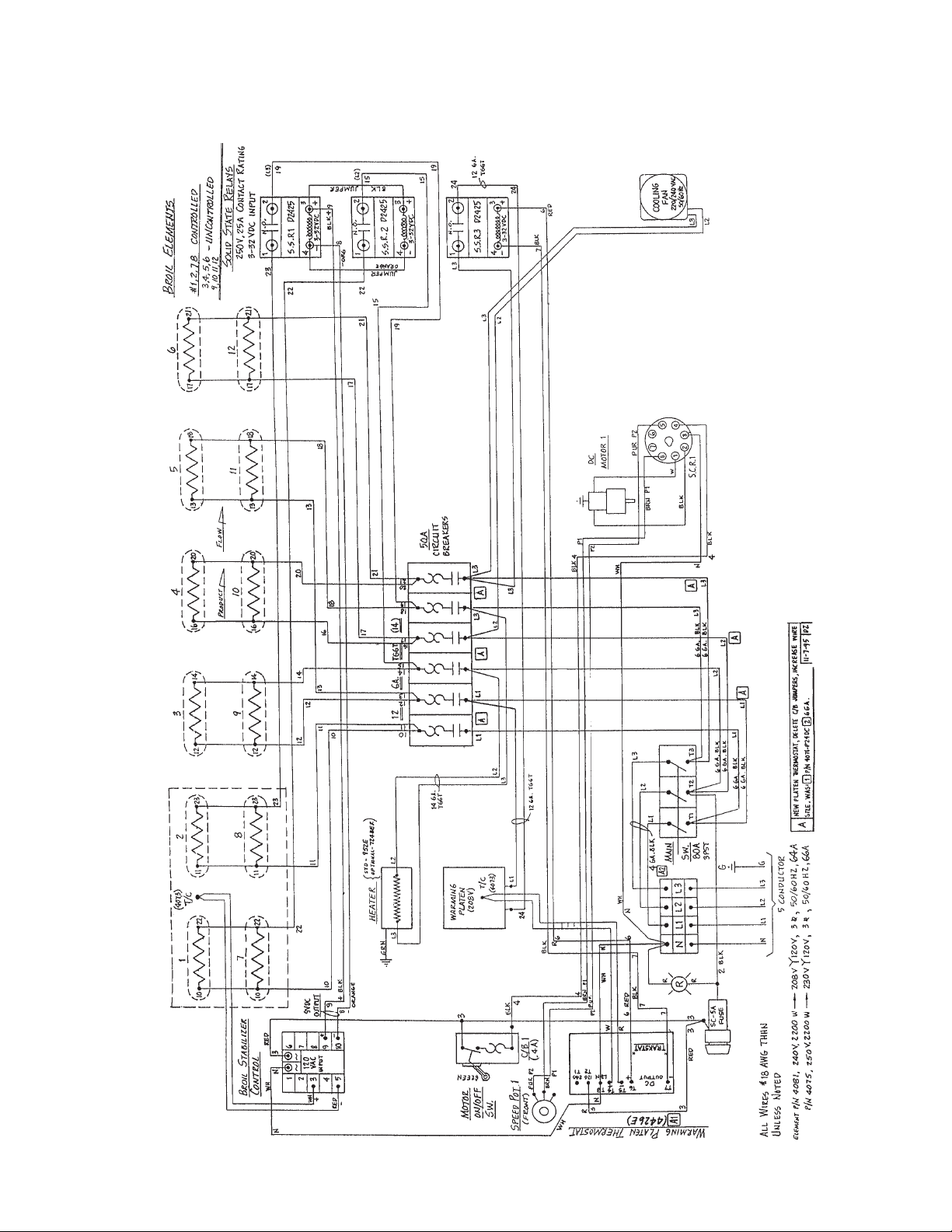
22
I. WIRING DIAGRAM
Models 952 Electric - Domestic U.S.A.
Page 23
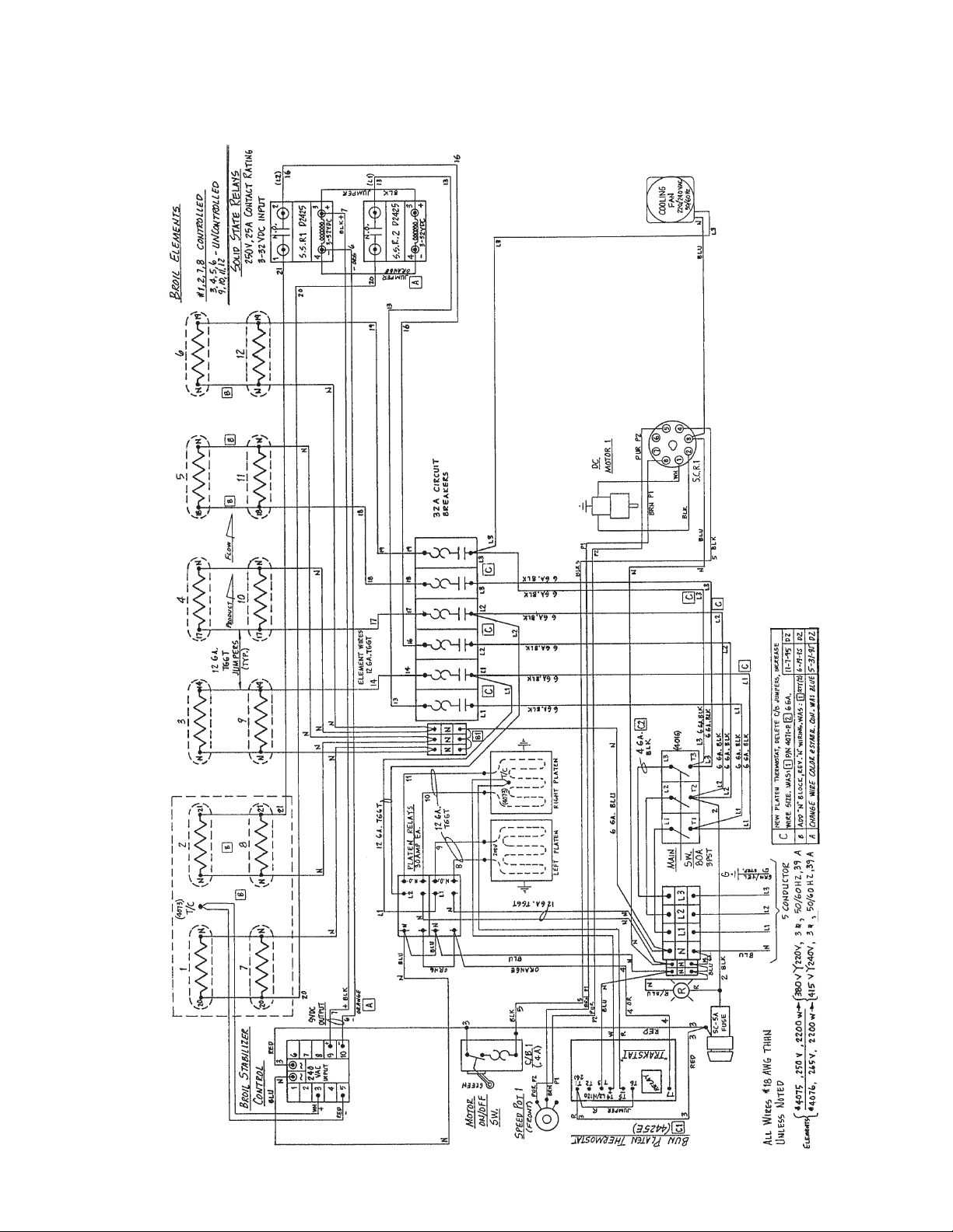
23
I. WIRING DIAGRAM
Models 952 Electric - Export
Page 24

24
I. WIRING DIAGRAM
Models 932 Electric - Domestic
Page 25
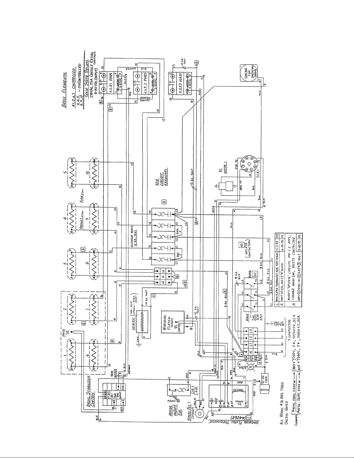
25
I. WIRING DIAGRAM
Models 932 Electric - Export
Page 26
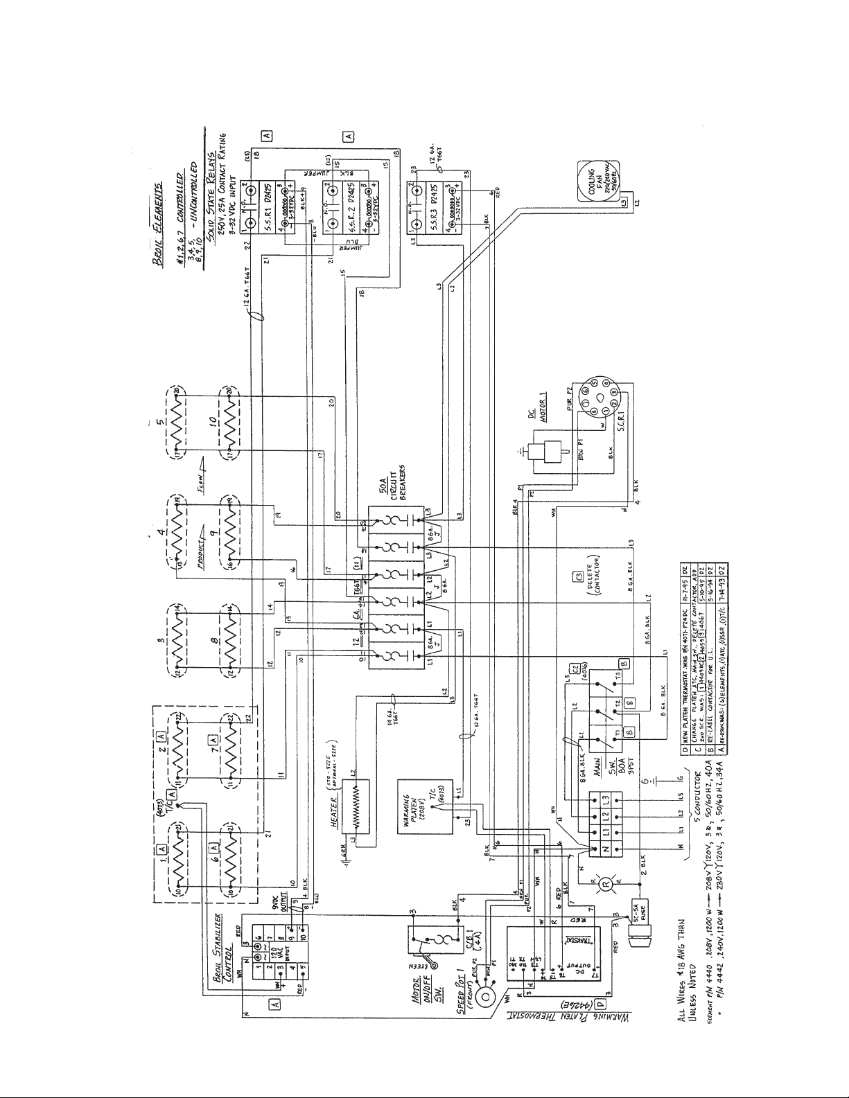
26
I. WIRING DIAGRAM
Models 922 Electric - Domestic
Page 27
27
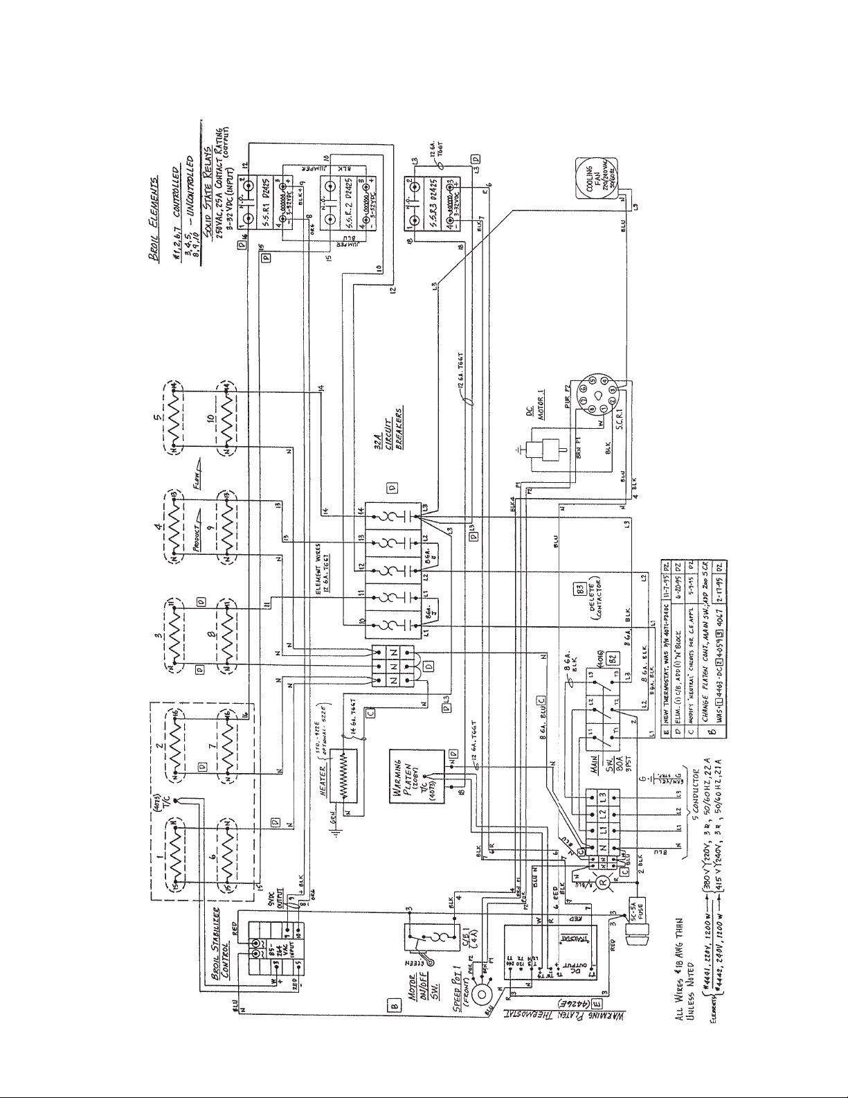
I. WIRING DIAGRAM
Models 922 Electric - Export
Page 28

Nieco Corporation • 15 Guittard Rd. • Burlingame, CA • 94010 • (415) 697-7335 • Fax (415) 697-3014
Reorder # 9999-99101 1/96 Printed in the USA
 Loading...