

Page 1

ENGLISH
1
2
4
TX
RX
TX
RX
TX
TX
RX
TX
RX
RX
TX
TX
RX
RX
RX
TX
TX
RX
RX
TX
FOTO 2
FT B
FT A
FOTO 2 II
FOTO
FOTO 1
FA 1
FA 2
FOTO II
FOTO 1 II
TX
RX
TX
RX
TX
RX
TX
RX
TX
TX
TX
RX
RX
RX
RX
RX
TX
FOTO 2
FT B
FOTO
FA 1
FA 2
FOTO II
RX
FOTO 2 II
FT C
TX
TX
FOTO 1
FOTO 1 II
FOTO
FA 1
FA 2
FOTO II
FOTO 1
FOTO 2 II
FOTO 2
FOTO 1 II
1 - Safety and installation instructions
n CAUTION! IMPORTANT INSTRUCTIONS: for personal safety it is important to read and follow these
instructions, and store them in a safe place. In case
of doubt, contact the Nice Support Service. Incor
rect installation is a safety hazard and can lead to
faulty operation. n Installation, hookup, programming
and maintenance shall only be performed by qualified
technicians, in compliance with the applicable laws,
standards, local regulations and these instructions. n
The transmitter component (TX) and the receiver com
ponent (RX) on the device shall be permanently installed
opposite one another on two vertical and parallel walls.
The walls shall be solid so they do not transmit any vi
brations to the photocells. n The photocells shall be installed in a position that protects them from accidental
impacts and that ensures easy access for maintenance.
n The photocells must be connected only to a NICE
control unit (or interface) equipped with “BlueBus” tech
nology. n The photocell must operate only when an object is placed between the TX and the RX). Operation by
reflection is prohibited. n To increase the level of safety
against malfunction, the photocells shall be connected to
a command control unit (or interface) equipped with the
“phototest” function. n The product is protected against
water and dust; it is therefore suited for normal outdoors
applications. It is however not suited for use in heavily
saline, acidic or potentially explosive atmospheres. Do
not install the equipment in areas subject to flooding or
water stagnation. n The electrical cables must enter the
photocell through one of the holes located on the bottom
of its mount and must be inserted from below. This so as
to prevent water dripping inside the product.
2 - Product description and intended use
This device is a photocell, namely a type-D presence detector, pursuant to the EN 12453 standard. It is part of
the Era-EP series, and is intended to be used on auto
mation systems for doors, gates, garage doors and similar installations. Any use other than that described is
to be considered improper and prohibited! The de
vice uses “BlueBus” technology, which enables the connection and communication among the photocells and
the command control unit (or interface) with two wires.
This is a “parallel” connection. Each pair of photocells
shall be assigned a specific task in the automation by the
insertion of jumpers. The product may be used together
with “FT210B” series devices, equipped with the “Blue
Bus” technology (see fig. 6 and 7), which enable the resolution of problem of electric connection with the sensitive edges installed on moving door leafs.
3 - Installation and connections
VERY IMPORTANT! – So that there is optical alignment
between the TX and the RX, make sure to check, prior
to installation, that the walls where the photocells
are to be mounted are parallel to one another. If the
walls are not parallel, it is suggested that adjustable pho
tocells (e.g. EPLOB) be used, as the alignment of these
photocells cannot be adjusted once their installation has
been completed.
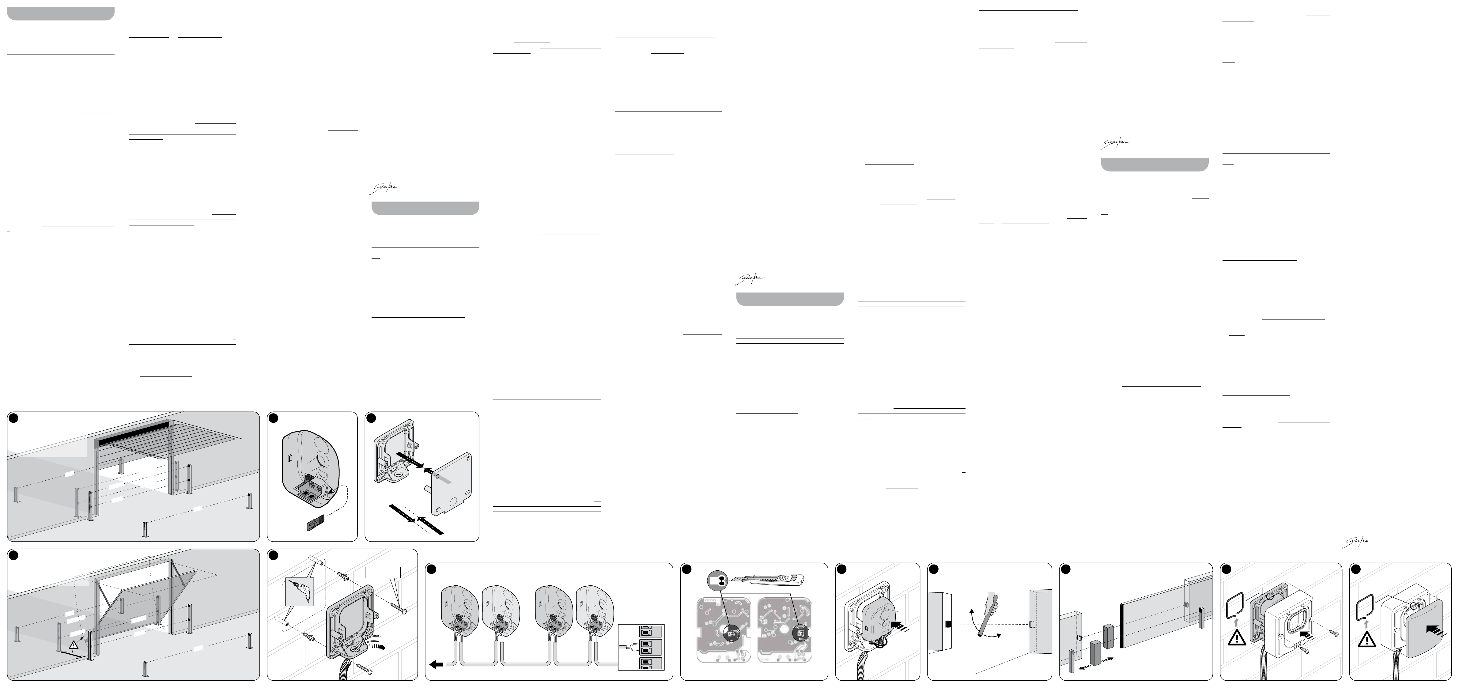
n 01. Prior to installation read the warnings in Chapter 1
and the data in Chapter 8. n 02. Disassemble and pre
pare th photocells (fig. 1, 2, 3, 4 and 5). n 03. Consult
the instruction manual for your control unit (or interface)
(or fig. 6, 7, 8, 9 and 10) to choose the detection func
tion and the corresponding installation position, that are
to be assigned to the pair of photocells. Note their iden
tification code number (e.g. “PHOTO 2”). To use one or
two pairs of photocells as the automatic opening control
device, choose either the FA1 and/or the FA2 functions.
n 04. Identify the identification code number chosen
previously in Table A (e.g. “PHOTO 2”). Note the dia
gram found under the code number and insert the jumpers in the TX and RX photocells, in the same position as
shown in the diagram. Note – Keep any unused jumpers
for any possible future need (fig. 11). n 05. If other pairs
of photocells are to be installed, repeat points 03 and 04
for each. Caution! – Each pair of photocells must use a
different jumper configuration than that used for the oth
er photocells in the automation. n 06. Attach the photocell brackets to the walls in the pre-established locations. Caution! – The two elements must be aligned on
a single axis (fig. 12-a), to facilitate the subsequent opti
cal aiming of the TX to the RX. If the walls do not facilitate
this alignment, it is suggested that, at this point, the pho
tocell brackets be installed provisionally (using adhesive
tape or other method), to then install them definitively
(fig. 12-b) only once testing has been completed (Chap
ter 4). Note – Only for single or double leaf sliding
gates – To avoid interference among the different “Blue
Bus” devices, position the TX and RX components as indicated on the tags in fig. 6 or 7. n 07. Disconnect the
power from the automation and if present, disconnect
the back-up battery. n 08. Connect the TX and RX components in “parallel” (fig. 13) using a two-wire bus cable.
Then, connect the bus cable to the “BlueBus” terminal
on the control unit (or interface). Matching polarity is not
required. n 09. Photocells used as the “automatic
opening control device” – If the photocells are set up
for this function (check in point 03), complete their in
stallation by cutting the electrical bridge between points
“A”, on the TX and RX circuit cards (fig. 14). n 10. In
-
stall the TX and RX modules on their supports (fig. 15).
n 11. Power the automation and perform the “BlueBus
device learning procedure”, found in the control unit (or
interface) instruction manual. Note – If this photocell is
going to be used to replace a previously existing photo
cell, the jumpers must be positioned in the same man-
-
ner as before. In this case the device learning procedure
is not required. n 12. Perform the test procedure as de
scribed in Chapter 4. n 13. Complete the installation as
-
shown in fig. 18, 19.
4 - Automation Testing
To make sure that the photocells are operating properly or to detect any interference from other devices, take
-
these steps. n 01. Power the automation and observe
the status of the LEDs on the TX and RX (fig. 15). Use
Table B to find out the meaning of the different statuses,
keeping in mind that proper operation is indicated only
when the two LEDs flash very slowly. If the status is not
compliant, perform the operations provided for in Table
B. In particular, if the alignment between TX and RX re
quires adjustment, move one or both the photocells until they are aimed at one another; that is, once the two
LEDs flash very slowly (= optimum reciprocal alignment).
n 02. Check their operation by blocking the line of sight
between them with a cylinder (Ø = 5 cm; L = 30 cm): first
pass the object close to the TX, then to the RX and, fi
nally, halfway between them (fig. 16). Make sure that in
each case the output switches from “Active” to “Alarm”
and back, and that the automation responds properly to
actuation of the photocell. n 03. Verify the correct ob
stacle detection as required by the EN 12445 standard,
using a parallelepiped (700 x 300 x 200 mm) with three
-
faces (one per dimension) with a matt black surface and
the others with glossy reflective surface (fig. 17).
Caution! – After having added, removed or replaced
any automation photocells, the entire automation system
must be tested, referring to the manuals for each of the
different devices.
5 - User warnings
Caution! – Photocells do not constitute actual safety de-
vices, but are rather safety aids. Although constructed
for maximum reliability, in extreme conditions they may
malfunction or fail, and this may not be immediately evi
dent. For this reason, and as a matter of good practice,
observe the following instructions: • Transit can only oc
cur if the gate or door are completely open and with the
leaves stationary. • NEVER TRANSIT while the gate or
door are closing or are about to close. • If you note any
sign of malfunction, shut off power to the automation im
mediately and use manual mode only (refer to the automation instruction manual). Contact your maintenance
staff/person for the control and the possible repair.
6 - Maintenance
Service the photocells at least every 6 months as follows:
1) release the motor as instructed in the user manual to
-
prevent the automation operating unexpectedly during
maintenance; 2) check for humidity, oxidation and for
eign bodies (such as insects) and remove them. In case
of doubt, replace the equipment; 3) clean the housing
– especially the lenses and glass panels – with a soft,
slightly damp cloth. Do not use alcohol, benzene, abra
sive or other cleaning products; these can affect the pol-
ished surfaces and compromise the operation of the
photocells; 4) run the tests indicated in “Tests”; 5) the
product is designed to work for at least 10 years in nor
mal conditions; we recommend increasing the frequency
of maintenance thereafter.
7 - Scrapping
This product is an integral part of the automation and
must therefore be scrapped together with it, in the same
way as indicated in the automation’s instruction manual.
-
8 - Technical specifications
Please note: the technical features refer to an ambient
temperature of 20°C. Nice S.p.a. reserves the right to
modify the products without altering their intended use
and essential functions.
-
n Type of product: presence detector for automated
gates and doors (type D per EN 12453). n Technol
ogy adopted: direct optical interpolation between TX
-
and RX units, with modulated IR beam. n Power sup
ply / output: The device may be connected only to a
-
control unit (or interface) equipped with “BlueBus” tech
nology. The electrical power is drawn from this device,
where the output signals are sent. n Maximum ab
sorbed power: 1 “BlueBus” unit. n TX beam angle:
20° (± 25%). n RX field angle: 8° (± 25%). n Range:
useful range 15m; maximum range 30m. The range may
be reduced by 50% in poor atmospheric conditions (fog,
rain, dust, etc.). n Detection capacity: opaque objects
larger than 50 mm along the line of sight between TX
and RX (max. speed 1.6 m/s). n Number of photocells
that may be connected: Up to 7 pairs of safety func
tion photocells may be installed and 2 pairs to control the
open command (automatic synchronisation avoids inter
ference among the different detectors). n Maximum
length of the wire: all components must be connected
in parallel. The sum of the lengths of all of the wires used
to connect the different components, including the wire
coming from the control unit shall not be greater than 50
metres. n Protection rating: IP 44 n Use in acid, sa
line or potentially explosive atmosphere: no. n Operating temperature: -20 to +50°C n Installation: el-
ements installed facing each other on two vertical parallel walls, or on an appropriate column support. n TX/
RX alignment adjustment: no. n Dimensions (single
component) / Weight (sum of two components): –
EPLB - EPLB/A, 70 x 70(h) x 30 mm / 165 g – EPMB
- EPMB/A, 50 x 80(h) x 28.5 mm / 143 g
9 - CE Declaration of Conformity
Nice S.p.A. hereby declares that the products: EPLB,
EPMB comply with the essential requirements and oth
er pertinent provisions defined by Directive 2004/108/
EC. The CE declaration of conformity can be viewed and
printed at the website www.nice-service.com, or may be
requested directly from Nice S.p.A.
Mr. Mauro Sordini (Chief Executive Officer)
-
1 - Avvertenze per la sicurezza e l’instal-
-
-
-
-
-
-
-
lazione
n ATTENZIONE! ISTRUZIONI IMPORTANTI: per la
sicurezza delle persone è importante leggere, ri
spettare e conservare queste istruzioni. In caso di
dubbi, chiedere chiarimenti al Servizio Assistenza
Nice. L’installazione non corretta pregiudica la si
curezza e provoca guasti. n Tutte le operazioni di in-
stallazione, collegamento, programmazione e manutenzione devono es sere effettuate esclusivamente da personale tecnico qualificato, rispettando le leggi, le normative, i regolamenti locali e le presenti is truzioni. n L’elemento trasmittente (TX) e l’elemento ricevente (RX) del
dispositivo devono essere fissati uno di fronte all’altro, in
modo permanente, su due pareti verticali e parallele tra
loro. Queste devono essere di materiale solido e non de
vono trasmettere vibrazioni alle fotocellule. n La posizione scelta per il fissaggio deve proteggere la fotocellula da
urti accidentali e deve garantire un facile accesso per la
manutenzione. n Le fotocellule devono essere collegate
esclusivamente a una centrale (o a un’interfaccia) di co
mando Nice, dotata di tecnologia “BlueBus”. n Il dispositivo deve funzionare esclusivamente per interpolazione
diretta tra l’elemento Tx e RX: è vietato il funzionamen
to per riflessione. n Per innalzare il livello di sicurezza ai
guasti è necesario collegare la fotocellula a una centra
le (o a un’interfaccia) di comando dotata della funzione
“fototest”. n Il prodotto è protetto contro le infiltrazioni
di pioggia e polvere; quindi è adatto all’uso nei norma
li “ambienti esterni”. In ogni caso non è adatto all’uso in
ambienti con atmosfera particolarmente salina, acida o
potenzialmente esplosiva. Evitare l’installazione anche in
luoghi soggetti a ristagni d’acqua e allagamenti. n I ca
vi elettrici devono entrare nella fotocellula attraverso uno
dei fori predisposti nella zona inferiore del suo supporto;
inoltre i cavi devono provenire dal basso. Questo eviterà
lo stillicidio di acqua all’interno del prodotto.
2 - Descrizione del prodotto e
ITALIANO
Istruzioni originali e complete
destinazione d’uso
Il presente dispositivo è una fotocellula, ovvero un rivelatore di presenza del tipo D, secondo la EN 12453. Fa
parte della serie Era-EP ed è destinato agli impianti di
automazione per porte, cancelli, portoni da garage e si
milari. Qualsiasi altro uso diverso da quello descrit-
to è da considerarsi improprio e vietato! Il dispositivo
è dotato di tecnologia “BlueBus” che consente il collega
mento e la comunicazione tra le fotocellule e la centrale
(o l’interfaccia) di comando, con due conduttori elettri
ci. Il collegamento avviene “in parallelo”; ad ogni coppia di fotocellule viene assegnata una funzione specifica
nell’automazione, attraverso l’inserimento di alcuni jum
-
per. Il prodotto è utilizzabile insieme ai dispositivi della
serie “FT210B”, dotati di tecnologia “BlueBus” (vedere
-
la fig. 6 e 7), che consentono di risolvere il problema dei
collegamenti elettrici dei bordi sensibili installati su ante
-
in movimento.
3 - Installazione e collegamenti
MOLTO IMPORTANTE! – Per ottenere l’allineamen-
to ottico tra TX e RX, è necessario controllare prima dell’installazione che le pareti scelte per il fissaggio degli elementi siano perfettamente parallele tra loro. Se non lo sono, si consiglia l’uso di fotocellu-
le orientabili (es. EPLOB) in quanto le presenti fotocellule
non hanno un sistema per regolare l’allineamento dopo il
-
loro fissaggio definitivo.
n 01. Prima dell’installazione leggere le avvertenze nel
-
capitolo 1 e i dati nel capitolo 8. n 02. Smontare e pre
parare le fotocellule (fig. 1, 2, 3, 4, 5). n 03. Consultare il
manuale istruzioni della vostra centrale (o dell’interfaccia)
di comando (oppure le fig. 6, 7, 8, 9, 10) per scegliere la
funzione di rilevazione e la posizione d’installazione ab
binata, che si desidera assegnare alla coppia di fotocel-
-
lule; annotare la loro sigla identificativa (es. “FOTO 2”). •
Per usare una o due coppie di fotocellule come disposi
tivo per il comando automatico della manovra di apertura, scegliere la funzione FA1 e/o FA2. n 04. Individuare
nella Tabella A la sigla scelta in precedenza (es. “FOTO
2”); osservare lo schema riportato sotto la sigla e inserire
i jumper nella fotocellula TX e RX, nella stessa posizione
mostrata dallo schema. Nota – Conservare i jumper non
utilizzati per un loro eventuale utilizzo futuro (fig. 11). n
05. Se si desidera installare ulteriori coppie di fotocellule,
ripetere per ognuna i punti 03 e 04. Attenzione! – Ogni
coppia di fotocellule deve utilizzare una configurazione di
jumper diversa da quelle utilizzate dalle altre fotocellule
presenti nell’automazione. n 06. Fissare i supporti delle
fotocellule alle pareti, nelle posizioni prestabilite. Atten
zione! – I due elementi devono essere allineati lungo uno
stesso asse (fig. 12-a), in modo da favorire il successivo
puntamento ottico tra TX e l’RX. Se le pareti non favo
riscono questo allineamento si consiglia, in questa fase,
di fissare i supporti delle fotocellule in modo provvisorio
(con nastro adesivo o altro), per poi fissarli in modo de
finitivo (fig. 12-b) soltanto alla fine del collaudo (capitolo
4). Nota – Solo per cancelli scorrevoli a singola o a
doppia anta – Per evitare interferenze fra i diversi dispo
sitivi “BlueBus” presenti, posizionare gli elementi TX e RX
come indicato dai cartigli presenti nella fig. 6 o 7. n 07.
Togliere l’alimentazione all’automazione; se è presente la
batteria tampone, scollegare anche questa. n 08. Colle
-
gare gli elementi TX e RX in “parallelo” (fig. 13) utilizzando un cavo bus con due conduttori elettrici; infine collegare il cavo bus al morsetto “BlueBus” presente sulla
-
centrale (o sull’interfaccia) di comando: non è necessario
rispettare alcuna polarità. n 09. Fotocellule usate co
me “dispositivo di comando automatico della manovra di apertura” – Se le fotocellule sono state predi-
sposte per questa funzione (verificare al punto 03), completare la loro installazione tagliando il ponte elettrico tra
i punti “A”, presenti sulle schede degli elementi TX e RX
(fig. 14). n 10. Fissare i moduli TX e RX nei loro suppor
ti (fig. 15). n 11. Alimentare l’automazione ed eseguire
-
la “procedura di apprendimento dei dispositivi BlueBus”,
riportata nel manuale istruzione della centrale (o dell’in
terfaccia) di comando. Nota – Se la presente fotocellula
viene usata per sostituire un’altra esistente, è necessario
posizionare i jumper nella stessa posizione precedente.
-
In questo caso non è necessario eseguire la procedura di
apprendimento dei dispositivi. n 12. Eseguire il Collaudo
descritto nel Capitolo 4. n 13. Completare l’installazione
-
come indicato nella fig. 18, 19.
4 - Collaudo dell’installazione
Per verificare il corretto funzionamento delle fotocellule o
rilevare le interferenze con altri dispositivi, procedere nel
modo seguente: n 01. Alimentare l’automazione e os
servare lo stato del Led posizionato sul TX e sull’RX (fig.
15); quindi, trovare nella Tabella B il significato dello sta
to tenendo presente che il funzionamento è ottimale solo
quando i due Led lampeggiano molto lentamente. Se lo
stato rilevato non è conforme, effettuare le azioni previste
nella Tabella B. In particolare, se serve migliorare l’alline
amento tra TX e RX spostare di poco una o entrambe le
fotocellule affinché puntino una verso l’altra, fino a quan
do i loro Led iniziano a lampeggiare molto lentamente (=
allineamento reciproco ottimale). n 02. Verificare l’effi
cienza della rilevazione interrompendo l’asse ottico tra le
due fotocellule con l’ausilio di un cilindro (Ø = 5 cm; L =
30 cm): passare l’oggetto prima vicino al TX, poi vicino
all’RX e, infine, a una distanza intermedia tra i due (fig.
16). Durante ogni passaggio accertarsi che l’uscita passi
dallo stato di “Attivo” a quello di “Allarme”, e viceversa, e
che l’automazione esegua l’azione prevista, conseguen
te all’intervento della fotocellula. n 03. Verificare il corret-
to rilevamento dell’ostacolo come richiesto dalla norma
EN 12445, utilizzando un parallelepipedo (700 x 300 x
200 mm) con tre facce (una per ogni dimensione) di ma
teriale nero opaco e le restanti facce in materiale lucido
riflettente (fig. 17).
Attenzione! – Dopo aver aggiunto, tolto o sostituito del
le fotocellule dall’automazione è necessario eseguire di
nuovo il collaudo dell’intera automazione, facendo riferi
mento ai manuali dei vari dispositivi.
5 - Avvertenze per l’uso
Attenzione! – Le fotocellule non sono un dispositivo di
sicurezza ma soltanto un dispositivo ausiliario alla sicu
Table A • Tabella A • Tableau A • Tabla A • Tabelle A • Tabela A • Tabel A
Photocells
positions
FOTO FOTO II FOTO 1 FOTO 1 II FOTO 2 FOTO 2 II FOTO 3 FA1(*) FA2(*)
Jumpers
positions
-
-
(*) • EN – Cut the electrical bridge “A” on the TX and RX wiring diagram (fig. 14). • IT – Tagliare il ponte elettrico “A” sulla scheda elettrica del TX e RX (g. 14). • FR – Couper le pont
électrique « A » sur la carte électrique du TX et du RX (fig. 14). • ES – Cortar el puente eléctrico “A” en la tarjeta eléctrica TX y RX (fig. 14). • DE – Schneiden Sie die elektrische Brücke „A“
auf der elektrischen Platine von TX und RX zu (Abb. 14). • PL – Przeciąć mostek elektryczny „A” na płycie elektrycznej nadajnika i odbiornika (rys. 14). • NL – Snijd de elektrische brug “A”
op de elektrische kaart van de TX en RX (afb. 14).
Table B • Tabella B • Tableau B
EN LED STATUS MEANING ACTION
-
Always off (TX, RX) – The photocell has no power supply or is
3 quick flashes, (pause), ... (TX, RX) – The pair of photocells has not been memo-
Very slow flashing (TX, RX) – The TX is transmitting properly. The RX is
Slow flashing
Fast flashing
Very fast flashing
Always on
-
-
-
-
-
-
-
-
-
-
IT STATO DEL LED SIGNIFICATO AZIONE
Sempre spento (TX, RX) – La fotocellula non è alimentata oppure è
3 lampeggi veloci, (pausa), ... (TX, RX) – La coppia di fotocellule non è memorizzata
Lampeggio molto lento
Lampeggio lento
Lampeggio veloce
Lampeggio molto veloce
Sempre acceso
FR ETAT DE LA LED SIGNIFICATION ACTION
Toujours éteinte (TX, RX) – La photocellule n’est pas alimentée ou est
3 clignotements rapides,
(pause), ...
Clignotement très lent
Clignotement lent
Clignotement rapide
Clignotement très rapide
Toujours allumée
rezza. Nonostante siano costruite per la massima affidabilità, in situazioni estreme possono avere malfunzionamenti o guastarsi e il problema potrebbe non essere subito evidente. Per questi motivi, e comunque come
buona regola, rispettare le seguenti avvertenze: • Il tran
sito attraverso il varco è consentito solo se il cancello o il
portone è completamente aperto e con le ante ferme. •
È ASSOLUTAMENTE VIETATO transitare mentre il can
cello o il portone si sta chiudendo o si prevede che la
chiusura sia imminente. • Se si verificano segni di mal
funzionamento togliere immediatamente l’alimentazione
all’automazione; eventualmente utilizzarla in modo esclu
sivamente manuale facendo riferimento al suo manuale
istruzioni. Quindi chiamare immediatamente il personale
abilitato per il controllo e l’eventuale riparazione.
6 - Manutenzione
Eseguire la manutenzione delle fotocellule almeno ogni 6
mesi, effettuando le seguenti operazioni: 1) sbloccare il
motore come descritto nel suo manuale istruzioni per im
pedire l’azionamento involontario dell’automazione du-
rante la manutenzione; 2) controllare l’eventuale presen-
za di umidità, ossidazioni e corpi estranei (ad esempio,
insetti), ed eliminarne la presenza. In caso di dubbi sosti
tuire il dispositivo; 3) pulire l’involucro esterno, – in particolare, le lenti e i vetrini, – utilizzando un panno morbido leggermente umido. Non usare sostanze detergenti a
base di alcol, benzene, abrasivi o similari; queste posso
no opacizzare le superfici lucide e pregiudicare il funzio-
namento della fotocellula; 4) eseguire il controllo funzio-
nale come descritto nel capitolo “Collaudo”; 5) il prodotto è progettato per funzionare almeno 10 anni in condizioni normali; trascorso questo periodo si consiglia di in-
-
tensificare la frequenza degli interventi di manutenzione.
7 - Smaltimento
Questo prodotto è parte integrante dell’automazione e
deve essere smaltito con essa, applicando gli stessi cri
teri riportati nel manuale istruzioni dell’automazione.
-
8 - Caratteristiche tecniche
Avvertenze: le caratteristiche tecniche sono riferite alla
temperatura ambientale di 20°C. Nice S.p.a. si riserva il
-
diritto di modificare i prodotti mantenendone comunque
faulty.
rised in the control unit (or the interface).
receiving an optimum signal.
(RX) – The RX is receiving a good signal. None; good operation.
(RX) – The RX is receiving a weak signal. Fair operation; the photocell glass should be cleaned.
(RX) – The RX is receiving a poor signal. Barely operational; clean the photocell glass and realign the TX and RX photocells.
(TX, RX) –The RX is receiving no signal. Check if there is an obstacle between the TX and the RX; clean the photocell glass and realign the TX and
guasta.
nella centrale (o nell’interfaccia) di comando.
(TX, RX) – Il TX trasmette regolarmente. L’RX riceve un
segnale ottimo.
(RX) – L’RX riceve un segnale buono. Nessuna; funzionamento buono.
(RX) – L’RX riceve un segnale scarso. Funzionamento discreto; si consiglia di eseguire la pulizia dei vetrini.
(RX) – L’RX riceve un segnale pessimo. Funzionamento al limite; eseguire la pulizia dei vetrini; fare di nuovo l’allineamento tra TX e RX.
(TX, RX) – L’RX non riceve alcun segnale. Vericare se c’è un ostacolo tra TX e RX; eseguire la pulizia dei vetrini; fare di nuovo l’allineamento tra TX e RX.
endommagée.
(TX, RX) – La paire de photocellules n’est pas mémori-
sée dans la logique (ou dans l’interface) de commande.
(TX, RX) – Le TX transmet normalement. Le RX reçoit
un excellent signal.
(RX) – Le RX reçoit un bon signal. Aucune ; bon fonctionnement.
(RX) – Le RX reçoit un signal faible. Fonctionnement moyen : nous conseillons de procéder au nettoyage des verres de protection.
(RX) – Le RX reçoit un signal très mauvais. Fonctionnement limite ; procéder au nettoyage des verres de protection ; procéder à un nouvel alignement
(TX, RX) – RX ne reçoit aucun signal. Vérifier s’il y a un obstacle entre TX et RX ; procéder au nettoyage des verres de protection ; procéder à un
la destinazione d’uso e le funzionalità essenziali.
n Tipologia del prodotto: rilevatore di presenza per
automazioni su cancelli e portoni (tipo D secondo la nor
ma EN 12453). n Tecnologia adottata: interpolazione
ottica diretta tra TX ed RX, con raggio infrarosso modu
lato. n Alimentazione/uscita: il dispositivo può essere
collegato esclusivamente a una centrale (o un’interfac
cia) di comando con tecnologia “BlueBus”. Da questa
preleva l’alimentazione elettrica e a questa invia i segna
li di uscita. n Corrente massima assorbita: 1 unità
“Bluebus”. n Angolo del raggio emesso dal TX: 20°
(± 25%). n Angolo dell’area di rilevamento dell’RX:
8° (± 25%). n Portata: portata utile 15m; portata mas
sima 30m. La portata può ridursi del 50% in presenza di
fenomeni atmosferici (nebbia, pioggia, polvere, ecc.). n
Capacità di rilevamento: oggetti opachi con dimen
sioni maggiori di 50 mm, presenti sull’asse ottico tra TX
ed RX (velocità massima di 1,6 m/s). n Numero di fo
tocellule collegabili: fino a 7 coppie di fotocellule con
funzione di protezione e 2 con funzione di comando di
apertura (il sincronismo automatico evita l’interferenza fra
i vari rilevatori). n Lunghezza massima del cavo: tutti
gli elementi devono essere collegati in parallelo. La som
ma delle lunghezze di tutti i cavi impiegati per collegare
i vari elementi tra loro, compreso il cavo che arriva alla
centrale, non deve superare i 50 m. n Grado di pro
-
tezione: IP 44 n Utilizzo in atmosfera acida, salina
o potenzialmente esplosiva: no. n Temperatura di
funzionamento: -20 ÷ +50°C n Montaggio: elementi
fissati uno di fronte all’altro, su due pareti verticali e paral
lele tra loro o su apposito supporto a colonna. n Siste-
ma per regolare l’allineamento tra TX e RX: no. n
Dimensioni (elemento singolo) / Peso (somma dei
due elementi): – EPLB - EPLB/A, 70 x 70(h) x 30 mm /
165 g – EPMB - EPMB/A, 50 x 80(h) x 28,5 mm / 143 g
-
9 - Dichiarazione CE di conformità
Nice S.p.A. dichiara che i prodotti: EPLB, EPMB sono
conformi ai requisiti essenziali ed alle altre disposizio
ni pertinenti, stabilite dalle direttive 2004/108/CE. La
dichiarazione di conformità CE può essere consultata
e stampata nel sito www.nice-service.com oppure può
Check that on the terminals of the photocell there is a voltage of approximately 8 to 12 V DC. If the voltage
is correct, it is likely that the photocell is faulty.
Make sure that each pair of photocells has a different jumper configuration than the others. Perform the device learning procedure (Chapter 3, point 11).
None; optimum TX - RX alignment.
RX photocells.
Accertarsi che sui morsetti della fotocellula sia presente una tensione di circa 8 - 12 Vdc; se la tensione è
corretta è probabile che la fotocellula sia guasta.
Accertarsi che ogni coppia di fotocellule abbia una congurazione di jumper diversa dalle altre. Fare la procedura di apprendimento dei dispositivi (capitolo 3, punto 11).
Nessuna; allineamento TX-RX ottimale.
S’assurer qu’une tension d’environ 8 - 12 Vcc est présentesur les bornes de la photocellule ; si la tension
est correcte, la photocellule est probablement en panne.
S’assurer que chaque paire de photocellules a une configuration de cavaliers différente des autres. Procé-
der à la reconnaissance des dispositifs (chapitre 3, point 11).
Aucune ; alignement TX-RX optimal.
entre TX et RX.
nouvel alignement entre TX et RX.
essere richiesta a Nice S.p.A.
Ing. Mauro Sordini (Amministratore delegato)
-
-
FRANÇAIS
-
-
1 - Consignes de sécurité et d’installation
n ATTENTION ! INSTRUCTIONS IMPORTANTES :
pour la sécurité des personnes, il est important de
lire, de respecter et de conserver ces instructions.
-
En cas de doutes, demander des précisions au ser
vice après-vente Nice. Une installation incorrecte
compromet la sécurité et cause des dommages.
n Toutes les opérations d’installation, de raccordement,
de programmation et de maintenance doivent être ef
-
fectuées uniquement par des techniciens qualifiés, en
observant les lois, les règlementations, les règlements
locaux et les présentes instructions. n L’élément émet
teur (TX) et l’élément récepteur (RX) du dispositif doivent
être fixés l’un en face de l’autre, de façon permanente,
sur deux murs verticaux, parallèles entre eux. Ces der
niers doivent être composés d’un matériau solide et ne
doivent pas transmettre de vibrations aux photocellules.
-
n L’emplacement choisi pour la fixation doit protéger la
photocellule contre les chocs accidentels et garantir un
accès facile pour l’entretien. n Les photocellules doivent
être reliés uniquement à une logique (ou à une interface)
de commande Nice, équipée de technologie « BlueBus
». n Le dispositif doit être utilisé uniquement par inter
polation directe entre l’élément TX et RX : le fonctionnement par réflexion est interdit. n Pour augmenter le
niveau de sécurité face aux pannes, relier la photocel
lule à une logique de commande (ou à une interface)
équipée de la fonction «phototest ». n Le produit est
protégé contre les infiltrations de la pluie et de la pous
sière. Il peut donc être utilisé à l’extérieur. Dans tous les
cas, il n’est pas adapté pour une utilisation dans des
environnements à l’atmosphère particulièrement riche en
sel, acide ou potentiellement explosive. Éviter l’installa
tion dans des zones soumises à la stagnation de l’eau et
Tabla B • Tabelle B • Tabela B • Tabel B
ES ESTADO DEL LED SIGNIFICADO ACCIÓN
Siempre apagado (TX, RX) – La fotocélula no está alimentada o está
3 parpadeos rápidos, (pausa), ...
Parpadeo muy lento
Parpadeo lento
Parpadeo rápido
Parpadeo muy rápido
Siempre encendido
DE LED-STATUS BEDEUTUNG AKTION
Immer ausgeschaltet (TX, RX) – Die Fotozelle wird nicht mit Spannung ver-
3 Mal schnelles Blinken,
(Pause), ...
Sehr langsames Blinken
Langsames Blinken
Schnelles Blinken
Sehr schnelles Blinken
Immer eingeschaltet
PL STAN DIODY LED ZNACZENIE DZIAŁANIE
Zgaszona (nadajnik, odbiornik) – Fotokomórka nie jest zasilana
3 szybkie mignięcia, (pauza), ...
Bardzo wolne miganie
Wolne miganie
Szybkie miganie
Bardzo szybkie miganie
Świeci
NL STATUS VAN DE LED BETEKENIS HANDELING
Altijd uit (TX, RX) – De fotocel wordt niet gevoed of is defect. Controleer of op de klemmen van de fotocel een spanning van ca. 8 - 12 Vdc aanwezig is; als de spanning cor-
3 keer snel knipperen,
(pauze), ...
Heel langzaam knipperend
Langzaam knipperend
Snel knipperend
Zeer snel knipperend
Altijd aan (TX, RX) – De RX ontvangt geen enkel signaal. Controleer of er zich een obstakel tussen TX en RX bevindt; voer de reiniging van de glaasjes uit; voer opnieuw de
aux inondations. n Les câbles électriques doivent entrer
dans la photocellule à travers un des trous prévus dans
la partie inférieure de son support; en outre, les câbles
doivent arriver par le bas. Cela empêchera que l’eau ne
goutte à l’intérieur du produit.
2 - Description du produit et application
Cet appareil dispose d’une photocellule, un détecteur de
présence de type D, selon la norme EN 12453. Il fait
partie de la série Era-EP et est destiné à des systèmes
d’automatisme pour portails, portes, portes de garage,
etc. Toute autre utilisation que celle décrite doit
être considérée comme impropre et interdite! Le
dispositif est équipé de technologie « BlueBus » qui per
-
met la connexion et la communication entre les photocellules et la logique (ou l’interface) de commande, avec
deux conducteurs électriques. La connexion a lieu «en
parallèle» ; une fonction spéciale est attribuée à chaque
paire de photocellules dans l’automatisme, à travers l’in
sertion de cavaliers. Le produit est utilisable avec les dispositifs de la série « FT210B », équipés de technologie «
BlueBus » (voir fig. 6 et 7), qui permettent de résoudre
le problème des connexions électriques des bords sen
sibles sur des vantaux en mouvement.
-
3 - Installation et connexions
TRÈS IMPORTANT ! – Pour obtenir l’alignement op-
tique entre TX et RX, il faut s’assurer, avant l’installation, que les murs choisis pour la fixation des éléments sont parfaitement parallèles entre eux. S’ils
ne le sont pas, nous conseillons l’utilisation de photocel
lules orientables (par ex. EPLOB) car les photocellules
présentes ne disposent pas d’un système permettant de
régler l’alignement après leur fixation définitive.
-
n 01. Avant de procéder à l’installation, consulter atten
tivement les avertissements du chapitre 1 et les données
du chapitre 8. n 02. Démonter et préparer les photocel
lules (fig. 1, 2, 3, 4, 5). n 03. Consulter la notice d’ins-
tructions de votre logique (ou interface) de commande
(ou bien les fig. 6, 7, 8, 9, 10) pour choisir la fonction
de détection et la position d’installation associée, que
vous souhaitez attribuer à la paire de photocellules ; pre
nez note de leur sigle d’identification (par ex. « FOTO 2
averiada.
(TX, RX) – El par de fotocélulas no está memorizado
en la central (o en la interfaz) de mando.
(TX, RX) – El TX transmite regularmente. El RX recibe
una señal óptima.
(RX) – El RX recibe una señal buena. Ninguna, funcionamiento correcto.
(RX) – El RX recibe una señal escasa. Funcionamiento discreto; se recomienda limpiar los vidrios.
(RX) – El RX recibe una señal pésima. Funcionamiento al límite; limpiar los vidrios y repetir la alineación entre TX y RX.
(TX, RX) – El RX no recibe ninguna señal. Verificar si hay un obstáculo entre TX y RX; limpiar los vidrios; repetir la alineación entre TX y RX.
sorgt oder ist defekt.
(TX, RX) – Das Fotozellenpaar ist nicht in der Steue-
rungszentrale (oder in der Schnittstelle) gespeichert.
(TX, RX) – TX übermittelt regelmäßige Signale. RX
empfängt ein optimales Signal.
(RX) – RX empfängt ein gutes Signal. Keine; gute Betriebstüchtigkeit
(RX) – RX empfängt ein mangelhaftes Signal. Ausreichende Funktionstüchtigkeit; es wird empfohlen, die Gläser zu reinigen.
(RX) – RX empfängt ein sehr schlechtes Signal. Betriebsfähigkeit grenzwertig; reinigen Sie die Gläser; führen Sie eine neuerliche Ausrichtung zwischen TX und RX
(TX, RX) – RX empfängt überhaupt kein Signal. Vergewissern Sie sich, dass kein Hindernis zwischen TX und RX vorhanden ist; reinigen Sie die Gläser; führen Sie
lub jest uszkodzona.
(nadajnik, odbiornik) – Para fotokomórek nie jest
wczytana do centrali sterującej (lub interfejsu).
(nadajnik, odbiornik) – Nadajnik nadaje w sposób
prawidłowy. Odbiornik odbiera optymalny sygnał.
(odbiornik) – Odbiornik odbiera sygnał dobrej jakości. Brak; prawidłowe funkcjonowanie.
(odbiornik) – Odbiornik odbiera sygnał słabej jakości. Średnia jakość funkcjonowania; zaleca się wyczyszczenie szybek.
(odbiornik) – Odbiornik odbiera sygnał złej jakości. Bardzo złe funkcjonowanie; wyczyścić szybki; wykonać nowe wyrównanie nadajnika i odbiornika.
(nadajnik, odbiornik) – Odbiornik nie odbiera żad-
nego sygnału.
(TX, RX) – Het paar fotocellen is niet opgeslagen in de
besturingseenheid (of in de interface).
(TX, RX) – De TX verzendt normaal. De RX ontvangt
een optimaal signaal.
(RX) – De RX ontvangt een goed signaal. Geen; goede werking.
(RX) – De RX ontvangt een slecht signaal. Discrete werking; er wordt aanbevolen de glaasjes te reinigen.
(RX) – De RX ontvangt een zeer slecht signaal.
»). • Pour utiliser une ou deux paires de photocellules
comme dispositif de commande automatique de la ma
nœuvre d’ouverture, choisir la fonction FA1 et/ou FA2. n
04. Identifier dans le Tableau A le sigle choisi précédem
ment (par ex. « FOTO 2 ») ; observer le schéma figurant
sous le sigle et introduire les cavaliers dans les photo
cellules TX et RX, dans la même position indiquée sur le
schéma. Remarque – Conserver les cavaliers non utili
sés pour une éventuelle utilisation future (fig. 11). n 05.
Pour installer des paires de photocellules supplémen
taires, répéter pour chacune d’elles les instructions des
points 03 et 04. Attention! – Chaque paire de photocel
lules doit utiliser une configuration de cavalier autre que
-
celles utilisées par les autres photocellules présentes
dans l’automatisme. n 06. Fixer les supports des photo
cellules aux murs, aux endroits prévus. Attention! – Les
deux éléments doivent être alignés sur un axe unique
(fig. 12-a), de manière à favoriser ensuite le pointement
-
optique entre TX et RX. Si les murs ne favorisent pas ce
alignement, nous conseillons, au cours de cette phase,
de fixer les supports des photocellules de façon provi
soire (avec du ruban adhésif ou autre), et de les fixer en-
-
suite de façon définitive (fig. 12-b) uniquement à la fin de
la procédure d’essai (chapitre 4). Remarque – Unique
ment pour portails coulissants à un ou à deux vantaux – Pour éviter des interférences entre les différents
dispositifs « BlueBus » présents, positionner les éléments
TX et RX comme indiqué par les encadrements présents
à la fig. 6 ou 7. n 07. Couper l’alimentation de l’auto
matisme ; en cas de présence de batterie tampon, la
-
déconnecter elle aussi. n 08. Connecter les éléments TX
et RX en « parallèle » (fig. 13) en utilisant un câble bus à
deux conducteurs électriques ; connecter enfin le câble
bus à la borne « BlueBus » présente sur la logique (ou
sur l’interface) de commande : il n’est pas nécessaire
de respecter une polarité quelconque. n 09. Photocel
lules utilisées comme « dispositif de commande
automatique de la manœuvre d’ouverture » – Si les
photocellules ont été prévues pour cette fonction (véri
fier au point 03), compléter leur installation en coupant
le pont électrique entre les points « A », présents sur
-
les cartes des éléments TX et RX (fig. 14). n 10. Fixer
les modules TX et RX sur leurs supports (fig. 15). n 11.
Cerciorarse de que en los bornes de la fotocélula haya una tensión de 8 - 12 Vdc; si la tensión es correcta, es
probable que la fotocélula esté averiada.
Cerciorarse de que cada par de fotocélulas tenga una configuración de jumpers diferente de los otros. Ejecutar el
procedimiento de adquisición de los dispositivos (capítulo 3, punto 11).
Ninguna; alineación TX-RX óptima.
Vergewissern Sie sich, dass an den Klemmen der Fotozellen eine Spannung von ca. 8-12 V DC vorhanden ist.
Falls der Spannungswert korrekt ist, ist die Fotozelle wahrscheinlich beschädigt.
Vergewissern Sie sich, dass jedes Fotozellenpaar über eine Jumper-Konfiguration verfügt, die sich von den anderen unterscheidet. Führen Sie das Einlernungsverfahren der Vorrichtungen durch (Kapitel 3, Punkt 11).
Keine; Ausrichtung TX-RX optimal.
durch.
eine neuerliche Ausrichtung zwischen TX und RX durch.
Sprawdzić, czy w zaciskach fotokomórki jest obecne napięcie około 8 - 12 Vdc; jeżeli napięcie jest prawidłowe,
prawdopodobnie nastąpiło uszkodzenie fotokomórki.
Należy się upewnić, że każda para fotokomórek posiada konfigurację zworek inną od pozostałych. Przeprowadzić
procedurę wczytywania urządzeń (rozdział 3, punkt 11).
Brak; optymalne wyrównanie nadajnika i odbiornika.
Sprawdzić, czy między nadajnikiem i odbiornikiem znajduje się przeszkoda, wyczyścić szybki; wykonać nowe wyrównanie między nadajnikiem i odbiornikiem.
rect is, is de fotocel waarschijnlijk defect.
Controleer of iedere paar fotocellen een andere jumperconfiguratie heeft dan de rest. Voer de leerprocedure van
de inrichtingen uit (hoofdstuk 3, punt 11).
Geen; optimale uitlijning TX-RX.
Werking heeft de limiet bereikt; voer de reiniging van de glaasjes uit; voer opnieuw de uitlijning tussen TX en RX uit.
uitlijning tussen TX en RX uit.
Alimenter l’automatisme et effectuer la « procédure de
reconnaissance des dispositifs BlueBus », décrite dans
le manuel d’instructions de la logique (ou de l’interface)
de commande. Remarque – Si la présente photocellule
est utilisée pour en remplacer une autre déjà existante,
il faut positionner les cavaliers dans la même position
qu’avant. Dans ce cas, il n’est pas nécessaire de procé
der à la reconnaissance des dispositifs. n 12. Effectuer
la procédure d’essai décrite au Chapitre 4. n 13. Com
pléter l’installation tel que décrit fig. 18, 19.
-
-
4 - Essai de l’automatisme
Pour s’assurer du bon fonctionnement des photocellules
ou pour détecter des interférences avec d’autres dispo
sitifs, procéder comme suit. n 01. Alimenter l’automa-
tisme et observer l’état de la Led située sur TX et sur RX
(fig. 15) ; trouver ensuite dans le Tableau B à quoi cor
respond cet état en sachant que le fonctionnement est
optimal quand les deux Led clignotent très lentement. Si
l’état constaté n’est pas conforme, effectuer les actions
prévues dans le Tableau B. S’il s’avère notamment né
cessaire d’améliorer l’alignement entre TX et RX, déplacer légèrement une photocellule ou les deux afin qu’elles
-
pointent l’une vers l’autre, jusqu’à ce que leurs Led com
mencent à clignoter très lentement (= alignement réci-
proque optimal). n 02. Vérifier l’efficacité de la détection
en interrompant l’axe optique entre les deux photocel
lules à l’aide d’un cylindre (Ø = 5 cm, L = 30 cm): pas-
ser l’objet tout d’abord à proximité du TX, puis du RX et,
enfin, à une distance intermédiaire entre les deux (fig. 16).
Lors de chaque passage, s’assurer que la sortie passe
de l’état de «actif» à «alarme», et vice-versa, et que l’au
tomatisme effectue l’action prévue suite à l’intervention
de la photocellule. n 03. Vérifier la bonne détection de
l’obstacle comme l’exige la norme EN 12445, en utilisant
-
un parallélépipède (700 x 300 x 200 mm) avec trois faces
(une pour chaque dimension) de matériau noir mat et les
autres faces en matériau brillant réfléchissant (fig. 17).
Attention! – Après avoir ajouté, enlevé ou remplacé des
photocellules de l’automatisme, il faut effectuer une nou
velle procédure d’essai de tout l’automatisme, en suivant
les instructions des notices des différents dispositifs.
EN - Instructions and warnings for
installation and use
IT - Istruzioni ed avvertenze per
l’installazione e l’uso
FR - Instructions et avertissements
pour l’installation et l’utilisation
ES - Instrucciones y advertencias
para la instalación y el uso
DE - Installierungs-und
Gebrauchsanleitungen und
Hinweise
PL - Instrukcje i ostrzeżenia do
instalacji i użytkowania
NL - Aanwzingen en aanbe-
velingen voor installatie en gebruik
5 - Recommandations pour l’utilisation
Attention! - Les photocellules ne sont pas un dispositif de sécurité mais uniquement un dispositif auxiliaire de
sécurité. Même si elles sont construites pour une fiabilité
maximale, dans les situations extrêmes, elles peuvent mal
fonctionner ou tomber en panne, et le problème risque
de ne pas être immédiatement évident. Pour ces raisons,
et comme bonne règle de base, prendre les précautions
suivantes : • Le passage n’est possible que si le por
tail ou la porte est complètement ouverte et ses vantaux
à l’arrêt. • IL EST STRICTEMENT INTERDIT de passer
quand le portail ou la porte se referme ou si on s’attend à
ce que la fermeture soit imminente. • En cas de mauvais
fonctionnement, couper immédiatement l’alimentation de
l’automatisme; l’utiliser au besoin uniquement en mode
manuel en se référant à sa notice d’instruction. Ensuite,
appeler immédiatement un technicien qualifié pour une
inspection et, éventuellement, une réparation.
-
6 - Entretien
-
Effectuer l’entretien des photocellules, au moins tous les
6 mois, en procédant comme suit: 1) débrayer le moteur
comme décrit dans sa notice d’instructions pour éviter
toute manipulation involontaire de l’automatisme pen
dant les travaux d’entretien; 2) vérifier la présence éven-
tuelle d’humidité, d’oxydation et de corps étrangers (par
exemple, insectes), et éliminer le cas échéant. En cas de
doute, remplacer le dispositif; 3) nettoyer le boîtier et
notamment les lentilles et les vitres, en utilisant un chiffon
-
doux imbibé d’un peu d’eau. Ne pas utiliser de produits
de nettoyage contenant de l’alcool, du benzène, des
abrasifs ou autres produits similaires; ils risquent d’opa
cifier les surfaces brillantes et de compromettre le fonc-
-
tionnement de la photocellule; 4) effectuer le contrôle
du fonctionnement comme décrit dans le chapitre «Es
sais»; 5) le produit est conçu pour fonctionner au moins
-
10 ans dans des conditions normales, après quoi nous
conseillons d’augmenter la fréquence des opérations de
maintenance.
-
7 - Mise au rebut
Ce produit est partie intégrante de l’automatisme et doit
être éliminé avec ce dernier, en appliquant les mêmes
critères indiqués dans le manuel d’instruction de l’auto
-
matisme.
8 - Caractéristiques techniques
Avertissements: les caractéristiques techniques se ré-
fèrent à une température ambiante de 20°C. Nice S.p.a.
se réserve le droit de modifier les produits, tout en conser
vant l’usage prévu et les caractéristiques essentielles.
n Type de produit: détecteur de présence pour auto
matisme de portails et portes (type D selon la norme EN
-
12453). n Technologie adoptée: interpolation optique
directe entre TX et RX, avec infrarouge modulé. n Ali
Nice
Photocells
EPLB
EPLB/A
EPMB
EPMB/A
EPMB - EPMB/A
EPLB - EPLB/A
IS0262A01MM_24-02-2016
Nice SpA
Oderzo TV Italia
info@niceforyou.com
www.niceforyou.com
mentation / sortie : le dispositif ne peut être connecté
qu’à une logique (ou à une interface) de commande à
technologie « BlueBus ». C’est de celle-ci qu’il prélève
son alimentation électrique et c’est à elle qu’il envoie les
signaux de sortie. n Courant maximum absorbé: 1
unité «BlueBus». n Angle du rayon émis par TX :
20° (+/- 25%). n Angle de la détection de RX: 8° (±
25%). n Portée: portée utile 15 m; portée maximum
30 m. La portée peut être réduite de 50% en présence
de phénomènes atmosphériques (brouillard, pluie, pous
sière, etc.). n Capacité de détection: objets opaques
ayant des tailles supérieures à 50 mm, présents sur l’axe
optique entre TX et RX (vitesse maximale de 1,6 m/s). n
Nombre de photocellules raccordables : jusqu’à 7
paires de photocellules avec fonction de protection et 2
avec fonction de commande d’ouverture (la synchroni
sation automatique évite l’interférence entre les différents
détecteurs). n Longueur maximale du câble : tous les
éléments doivent être connectés en parallèle. La somme
des longueurs de tous les câbles utilisés pour raccorder les divers éléments entre eux, y compris le câble qui
arrive à la logique de commande, ne doit pas dépasser 50 m de long. n Indice de protection : IP 44 n
Utilisation dans une atmosphère acide, saline ou
-
potentiellement explosive: non. n Température de
fonctionnement: de -20 à +50°C n Installation: élé-
ments fixés l’un en face de l’autre, sur deux murs verticaux, parallèles entre eux ou sur un support colonne
prévu à cet effet. n Système pour régler l’aligne-
ment entre TX et RX: non. n Dimensions (élément
individuel) / Poids (somme des deux éléments): –
EPLB - EPLB/A, 70 x 70(h) x 30 mm / 165 g – EPMB
-
- EPMB/A, 50 x 80(h) x 28,5 mm / 143 g
9 - Déclaration de conformité
Nice S.p.A. déclare que les produits: EPLB, EPMB sont
conformes aux exigences essentielles et autres dispositions pertinentes, prévues par les directives 2004/108/
CE. La déclaration de conformité CE peut être consultée
et imprimée sur le site www.nice-service.com ou bien
peut être demandée à Nice S.p.A.
Ing. Mauro Sordini (Chief Executive Officer)
-
-
-
-
-
-
1 2 3 4 5
6 7
• EN - Single leaf sliding gate • IT - Cancello scorrevole ad anta singola • FR - Portail coulissant à un seul vantail • ES - Puerta de corredera de
una hoja • DE - Einteiliges schiebetor • PL - Brama przesuwna z jednym skrzydłem • NL - Schuifpoort met enkele vleugel
• EN - Synchronised leafs sliding gate • IT - Cancello scorrevole ad ante contrapposte • FR - Portail coulissant
à vantaux opposés • ES - Puerta de corredera de hojas contrapuestas • DE - Schiebetor mit entgegengesetzt angebrachten torflügeln • PL - Brama przesuwna z dwoma przeciwleżącymi
skrzydłami • NL - Schuifpoort met tegengestelde vleugels
8
• EN - Swing gate • IT - Cancello a battente • FR - Portail battant • ES - Puerta de batiente • DE - Drehtor
• PL - Brama skrzydłowa • NL - Kanteldeur voor garage
Page 2
ESPAÑOL
Led
YES
NO!
pz. 2
Ø 3,5 x 35
FOTO 1
FOTO 1 II
FA 1
FA 2
FOTO
FOTO II
FA 1
FA 2
FOTO 1
FOTO 1 II
FOTO
FOTO II
TX
RX
A
TX
RX
TX
RX
BlueBus
1 - Advertencias para la seguridad y la
instalación
n ¡ATENCIÓN! INSTRUCCIONES IMPORTANTES:
para la seguridad de las personas es importante
leer, respetar y guardar estas instrucciones. Ecaso
de dudas, pedir aclaraciones al Servicio de Asis
tencia Nice. La instalación incorrecta perjudica la
seguridad y provoca averías. n Todas las operacio
nes de instalación, de conexión, de programación y de
mantenimiento del producto deben ser realizadas exclu
sivamente por personal técnico cualificado, respetando
las leyes, las normativas, los reglamentos locales y estas
instrucciones. n El elemento transmisor (TX) y el elemen
to receptor (RX) del dispositivo se deben fijar uno frente
al otro de manera permanente sobre dos paredes verti
cales paralelas entre sí. Las paredes deben ser de material sólido y no deben transmitir vibraciones a las fotocélulas. n La posición elegida para la fijación debe proteger
la fotocélula contra cualquier golpe y garantizar un fácil
acceso para el mantenimiento. n Las fotocélulas se de
ben conectar exclusivamente a una central (o a una interfaz) de mando Nice dotada de tecnología “BlueBus”.
n El dispositivo debe funcionar exclusivamente por in
terpolación directa entre Tx y Rx; el funcionamiento por
reflexión está prohibido. n Para aumentar el nivel de se
guridad en caso de desperfectos, es necesario conectar la fotocélula a una central (o a una interfaz) de mando
dotada de función “fototest”. n El producto está prote
gido contra las infiltraciones de lluvia y polvo, por lo que
se puede utilizar en ambientes exteriores. Sin embargo,
no debe utilizarse en atmósferas particularmente salinas,
ácidas o con peligro de explosión. Evitar la instalación en
lugares sujetos a estancamientos de agua e inundacio
nes. n Los cables eléctricos deben entrar en la fotocélula por uno de los orificios situados en la zona inferior del
soporte; además, los cables deben provenir desde aba
jo. Esto servirá para prevenir el estancamiento de agua
dentro del producto.
2 - Descripción del producto y destino
de uso
Este dispositivo es una fotocélula, o detector de presencia de tipo D, según la norma EN 12453. Forma parte de
la serie Era-EP y está destinado a los sistemas de au
tomatización para puertas, cancelas, portones de garaje
y afines. Está prohibido cualquier uso diferente de
aquel descrito en este manual. El dispositivo está do
tado de tecnología “BlueBus”, que permite la conexión
y la comunicación entre las fotocélulas y la central (o
la interfaz) de mando con dos conductores eléctricos.
La conexión es “en paralelo”; a cada par de fotocélulas
se asigna una función específica en la automatización,
mediante la colocación de algunos jumpers. El producto
se puede utilizar junto con los dispositivos de la serie
“FT210B”, dotados de tecnología “BlueBus” (ver la fig. 6
y 7), que permiten resolver el problema de las conexio
nes eléctricas de las bandas sensibles instaladas en las
hojas en movimiento.
3 - Instalación y conexiones
¡MUY IMPORTANTE! – Para lograr la alineación óptica
entre TX y RX es necesario comprobar, antes de la
instalación, que las paredes elegidas para la fija
ción de los elementos sean perfectamente paralelas entre sí. En caso contrario, se recomienda el uso de
fotocélulas orientables (ej. EPLOB), ya que las presentes
fotocélulas carecen de un sistema para regular la alinea
ción después de la fijación definitiva.
9
• EN - Sectional door
• IT - Garage sezionale
• FR - Porte sectionnelle
• ES - Garaje seccional
• DE - Sektionaltor
• PL - Brama garażowa sekcyjna
• NL - Sectionaalgaragedeur
10
• EN - Up & over garage doors
• IT - Garage basculante
• FR - Porte de garage basculante
• ES - Garaje basculante
• DE - Garagenkipptor
n 01. Antes de la instalación, leer las advertencias en el
capítulo 1 y los datos en el capítulo 8. n 02. Desmontar
y preparar las fotocélulas (fig. 1, 2, 3, 4, 5). n 03. Con
sultar el manual de instrucciones de la central (o de la interfaz) de mando (o las fig. 6, 7, 8, 9, 10) para elegir la
función de detección y la posición de instalación que se
desee asignar al par de fotocélulas; tomar nota de la si
gla de identificación (ej. “FOTO 2”). • Para utilizar uno o
dos pares de fotocélulas como dispositivo para el man
do automático de la maniobra de apertura, elegir la función FA1 y/o FA2. n 04. Identificar en la Tabla A la sigla
-
elegida anteriormente (ej. “FOTO 2”); observar el esque
ma debajo de la sigla y colocar los jumpers en la foto-
célula TX y RX en la posición mostrada por el esquema.
Nota – Conservar los jumpers no utilizados para el futuro
(fig. 11). n 05. Si se desea instalar más pares de foto
células, repetir los puntos 03 y 04 por cada una. ¡Aten-
ción! – Cada par de fotocélulas debe utilizar una confi-
guración de jumpers diferente de aquellas utilizadas por
las otras fotocélulas presentes en la automatización. n
-
06. Fijar los soportes de las fotocélulas en las paredes,
en las posiciones preestablecidas. ¡Atención! – Los dos
elementos deben estar alineados sobre un mismo eje
(fig. 12-a) para favorecer el sucesivo enfrentamiento óp
tico entre TX y RX. Si las paredes no favorecen el alinea-
miento, en esta fase se recomienda fijar los soportes de
las fotocélulas de manera provisoria (con cinta adhesiva
o afín); sólo al finalizar la prueba (capítulo 4) se fijarán de
manera definitiva (fig. 12-b). Nota – Sólo en caso de
puertas correderas de una o dos hojas – Para evi
tar interferencias entre los dispositivos “BlueBus”, poner
los elementos TX y RX como se ilustra en los esquemas
de la fig. 6 o 7. n 07. Desconectar la alimentación de
la automatización; desconectar también la batería de re
serva, si la hay. n 08. Conectar los elementos TX y RX
en “paralelo” (fig. 13) utilizando un cable bus con dos
conductores eléctricos; conectar el cable bus al borne
“BlueBus” de la central (o interfaz) de mando: no es ne
cesario respetar ninguna prioridad. n 09. Fotocélulas
utilizadas como “dispositivo de mando automáti
co de la maniobra de apertura” – Si las fotocélulas se
han predispuesto para esta función (verificar en el punto
03), completar la instalación cortando el puente eléctri
co entre los puntos “A” en las tarjetas de los elementos
TX y RX (fig. 14). n 10. Fijar los módulos TX y RX en sus
soportes (fig. 15). n 11. Alimentar la automatización y
ejecutar el “procedimiento de adquisición de los dispo
sitivos BlueBus” indicado en el manual de instrucciones
de la central (o interfaz) de mando. Nota – Si la presente
fotocélula se utiliza para sustituir otra existente, es nece
sario colocar los jumpers en la misma posición de la anterior. En este caso no es necesario ejecutar el procedi-
miento de adquisición de los dispositivos. n 12. Efectuar
la prueba descrita en el capítulo 4. n 13. Completar la
instalación como se indica en la fig. 18, 19.
4 - Prueba de la automatización
Para verificar el funcionamiento correcto de las fotocélulas o detectar las interferencias con otros dispositivos.
n 01. Alimentar la automatización y observar el estado
del led en el TX y en el RX (fig. 15); buscar en la Tabla
B el significado del estado teniendo en cuenta que el
funcionamiento es óptimo sólo cuando los dos leds par
padean muy lentamente. Si el estado detectado no es
conforme, realizar las acciones indicadas en la Tabla B.
En particular, si hay que mejorar la alineación entre TX
y RX, desplazar un poco una o ambas fotocélulas para
-
que apunten la una a la otra, hasta que sus leds empie
cen a parpadear muy lentamente (= alineación recíproca
óptima). n 02. Verificar la eficiencia de la detección in
terrumpiendo el eje óptico entre las dos fotocélulas con
el auxilio de un cilindro (Ø = 5 cm; L = 30 cm): hacerlo
pasar cerca del TX y luego del RX y, por último, a una
• PL - Garaz brama uchylna
• NL - Kanteldeur voor garage
distancia intermedia entre ambos (fig. 16). Durante cada
paso, comprobar que la salida conmute de “Activa” a
“Alarma”, y viceversa, y que la automatización ejecute
la acción prevista, consiguiente a la intervención de la
fotocélula. n 03. Comprobar que la detección del obstá
culo sea correcta según la norma EN 12445; utilizar un
paralelepípedo (700 x 300 x 200 mm) con tres caras de
material negro opaco (una cara de cada medida) y las
restantes de material brillante reflectante (fig. 17).
¡Atención! – Después de añadir, quitar o sustituir fotocé
lulas de la automatización es necesario volver a realizar
la prueba de toda la automatización siguiendo las ins
trucciones de los manuales de los distintos dispositivos.
5 - Advertencias para el uso
-
¡Atención! – Las fotocélulas no son un dispositivo de
seguridad, sino solamente un componente auxiliar de se
guridad. Si bien están construidas para asegurar la máxima fiabilidad, en situaciones extremas pueden presentar defectos de funcionamiento, o averiarse; además, el
problema podría no manifestarse de inmediato. Por eso
se recomienda respetar estas advertencias: • Transitar
solamente si la cancela o el portón están completamente
-
abiertos y con las hojas detenidas. • QUEDA ABSOLU
TAMENTE PROHIBIDO transitar mientras la cancela o el
portón se está cerrando o se está por cerrar. • En caso
de defectos de funcionamiento, desconectar inmediata
mente la alimentación de la automatización y utilizar la
automatización sólo en modo manual; consultar el ma
-
nual de instrucciones. Llamar inmediatamente a personal
habilitado para el control y la reparación.
6 - Mantenimiento
-
Realizar el mantenimiento de las fotocélulas al menos
cada 6 meses: 1) desbloquear el motor como se indi
ca en el manual de instrucciones para impedir el accionamiento involuntario de la automatización durante el
-
mantenimiento; 2) verificar si hay humedad, oxidación
o cuerpos extraños (por ejemplo, insectos) y eliminarlos.
-
En caso de dudas, sustituir el dispositivo; 3) limpiar la
cubierta externa, – especialmente las lentes y los vidrios
– utilizando un paño suave apenas humedecido. No utili
zar sustancias detergentes a base de alcohol, benceno,
abrasivos o afines; éstas podrían quitar brillo a las super
ficies y perjudicar el funcionamiento de la fotocélula; 4)
realizar un control del funcionamiento como se indica en
el capítulo “Prueba”; 5) el producto está diseñado para
funcionar al menos 10 años en condiciones normales;
transcurrido ese plazo, se recomienda aumentar la fre
cuencia del mantenimiento.
-
7 - Eliminación
Este producto forma parte de la automatización y, por
consiguiente, debe eliminarse junto con ella, aplicando
los criterios indicados en el manual de instrucciones de
la automatización.
8 - Características técnicas
Advertencias: las características técnicas se refieren
a una temperatura ambiental de 20°C. Nice S.p.a. se
reserva el derecho de modificar los productos, mante
niendo los usos y las funciones esenciales.
n Tipo de producto: detector de presencias para au
tomatizaciones en cancelas y portones (tipo D según la
norma EN 12453). n Tecnología adoptada: interpo
lación óptica directa entre TX y RX, con rayo infrarrojo
modulado. n Alimentación / salida: el dispositivo se
puede conectar exclusivamente a una central (o a una
interfaz) de mando con tecnología “BlueBus”, de la cual
-
obtendrá la alimentación eléctrica y a la cual transmitirá
las señales de salida. n Corriente máxima absorbi
da: 1 unidad “BlueBus”. n Ángulo del rayo emitido
por el TX: 20° (± 25%). n Ángulo del área de detec
11
-b
12
ción del RX: 8° (± 25%). n Alcance: alcance útil 15m;
alcance máximo 30m. El alcance puede reducirse en un
50% en presencia de fenómenos atmosféricos (niebla,
lluvia, polvo, etc.). n Capacidad de detección: objetos
-
opacos de más de 50 mm presentes sobre el eje óptico
entre TX y RX (velocidad máxima de 1,6 m/s). n Núme
ro de fotocélulas conectables: hasta 7 pares de fotocélulas con función de protección y 2 con función de
mando de apertura (el sincronismo automático evita la
interferencia entre los detectores). n Longitud máxima
del cable: todos los elementos deben conectarse en
paralelo. La suma de las longitudes de todos los cables
empleados para conectar los elementos entre sí, inclui
do el cable que viene de la central, no debe ser superior
a 50 m. n Grado de protección: IP 44 n Uso en at
mósfera ácida, salina o potencialmente explosiva:
no. n Temperatura de funcionamiento: -20 ÷ +50°C
n Montaje: elementos fijados uno frente al otro, sobre
dos paredes verticales paralelas entre sí o en su espe
cífico soporte de columna. n Sistema para regular la
alineación entre TX y RX: no. n Medidas (de un so
lo elemento) / Peso (suma de los dos elementos):
– EPLB - EPLB/A, 70 x 70(h) x 30 mm / 165 g – EPMB
- EPMB/A, 50 x 80(h) x 28,5 mm / 143 g
-
9 - Declaración de conformidad CE
Nice S.p.A. declara que los productos: EPLB, EPMB
cumplen con los requisitos esenciales y demás dis
posiciones pertinentes establecidas por las directivas
2004/108/CE. La declaración de conformidad CE se
puede consultar en el sitio www.nice-service.com o se
puede solicitar a Nice S.p.A.
Ing. Mauro Sordini (Chief Executive Officer)
-
DEUTSCH
1 - Hinweise zur Sicherheit und Installa-
-
-
-
-
-
-
-
-
tion
n ACHTUNG! WICHTIGE ANWEISUNGEN: Für die
Sicherheit von Personen ist es wichtig, dass Sie
diese Anweisungen lesen, befolgen und aufbewah
ren. Zögern Sie nicht, sich bei Fragen an den NiceKundendienst zu wenden. Eine fehlerhafte Instal
lation beeinträchtigt die Sicherheit und kann zu
Schäden führen. n Alle Installations-, Anschluss-, Pro
grammierungs- und Wartungsarbeiten am Produkt müssen von qualifiziertem Fachpersonal unter Einhaltung
der Gesetze, Bestimmungen und örtlichen Vorschriften
sowie der Anweisungen dieses Handbuchs ausgeführt
werden. n Das sendende Element (TX = Sender) und
das empfangende Element (RX = Empfänger) der Vor
richtung müssen jeweils einander gegenüber dauerhaft
an vertikalen und zueinander parallelen Wänden befes
tigt werden. Diese Wände müssen aus festem Material
bestehen und dürfen keine Vibrationen an die Fotozel
len übertragen. n Die Position für die Befestigung muss
so gewählt werden, dass der Schutz der Fotozelle vor
versehentlichen Stößen gewährleistet ist; darüber hinaus
muss sie leicht für Wartungsarbeiten zugänglich sein. n
Die Fotozelle müssen nur an eine Nice-Steuerzentrale
(oder eine Schnittstelle) mit „BlueBus“-Technologie an
geschlossen werden. n Die Fotozelle darf nur zur direkten Interpolation zwischen TX und RX eingesetzt werden;
der Einsatz zur Reflexion ist verboten. n Um den Stö
rungsschutzgrad zu erhöhen, muss die Fotozelle an eine Steuerzentrale (oder eine Schnittstelle) mit „FototestFunktion“ angeschlossen werden. n Das Produkt ist ge
gen Regen und Staub geschützt; deshalb ist es für den
-a
12
13
Einsatz in „normalen Außenräumen“ geeignet. Es ist jedoch nicht geeignet für besonders salzhaltige, saure
oder potentiell explosive Umgebungen. Auch an Orten
mit Überschwemmungsgefahr oder an denen sich Was
ser ansammeln kann, ist die Installation verboten. n Die
elektrischen Kabel können durch eine der vorgestanzten
-
Öffnungen im unteren Bereich der Halterung in die Foto
zelle eingeführt werden; die Kabel müssen von unten hineingeführt werden. Dadurch wird verhindert, dass sich
Wasser im Produkt ansammelt.
2 - Produktbeschreibung und Einsatz
-
Bei dem vorliegenden Gerät handelt es sich um eine
Fotozelle, oder ein Präsenzmelder vom Typ D, gemäß
-
EN 12453. Sie ist Teil der Reihe Era-EP und ist für den
Einsatz in Automatisierungsanlagen für Türen, Tore, Ga
ragentore und ähnliches gedacht. Jeder andere als
oben beschriebene Gebrauch ist unsachgemäß
-
und verboten! Das Gerät verfügt über „BlueBus“Technologie, die die Verbindung und die Kommunikation
-
zwischen den Fotozellen und der Steuerzentrale (bzw.
der Schnittstelle) mithilfe von zwei elektrischen Leitern
ermöglicht. Der Anschluss erfolgt in „Parallelschaltung“;
jedem Fotozellenpaar wird eine spezifische Funktion in
der Automatisierung zugewiesen. Dies erfolgt mithilfe
des Einsatzes von Jumpern. Das Produkt kann zusam
men mit Geräten der Serie „FT210B“ mit „BlueBus“-
Technologie verwendet werden (siehe Abb. 6 und 7),
die es ermöglichen, das Problem der elektrischen An
schlüsse der auf sich bewegenden Torflügeln installierten
Schaltleisten zu lösen.
3 - Installation und Anschlüsse
SEHR WICHTIG! – Um eine ordnungsgemäße opti-
sche Ausrichtung zwischen TX und RX zu gewährleisten, muss vor der Installation unbedingt überprüft
werden, ob die für die Befestigung der Elemente
gewählten Wände vollkommen parallel zueinander
verlaufen. Falls dies nicht der Fall ist, empfehlen wir den
Einsatz von schwenkbaren Fotozellen (z. B. EPLOB), da
die genannten Fotozellen über kein System zur Regu
lierung der Ausrichtung nach ihrer endgültigen Befestigung verfügen.
n 01. Lesen Sie vor der Installation die Hinweise im Kapi
-
tel 1 und die Angaben im Kapitel 8. n 02. Bauen Sie die
Fotozellen aus und bereiten Sie diese vor (Abb. 1, 2, 3,
-
4, 5). n 03. Schlagen Sie im Bedienungshandbuch Ihrer
Steuerzentrale (bzw. der Schnittstelle) nach (oder siehe
-
Abb. 6, 7, 8, 9, 10), um die Erfassungsfunktion und die
damit verknüpfte Installationsposition auszuwählen, die
dem Fotozellenpaar zugewiesen werden sollen. Notieren
Sie das entsprechende Identifikationskürzel (z. B. „FOTO
2“). • Um ein oder zwei Fotozellenpaare als Vorrichtung
für die automatische Steuerung der Öffnungsbewegung
-
zu verwenden, wählen Sie die Funktion FA1 und/oder
FA2. n 04. Ermitteln Sie in der Tabelle A das zuvor ge
-
wählte Kürzel (z. B. „FOTO 2“). Halten Sie sich an das
neben dem Kürzel angeführte Schema und setzen Sie
-
die Jumper in die Fotozelle TX und RX in jener Position
ein, die im Schema gezeigt wird. Hinweis – Bewahren
Sie die nicht verwendeten Jumper für eine etwaige Ver
wendung in der Zukunft auf (Abb. 11). n 05. Falls Sie
weitere Fotozellenpaare installieren möchten, wiederho
len Sie für jedes einzelne die unter Punkt 03 und Punkt
-
04 angeführten Schritte. Achtung! – Bei jedem Fotozel
lenpaar ist eine Jumper-Konfiguration zu verwenden, die
sich von jener unterscheidet, welche von den anderen in
-
der Automatisierung vorhandenen Fotozellen verwendet
wird. n 06. Befestigen Sie die Halterungen der Fotozel
len an den dafür vorgesehenen Positionen an den Wän-
-
den. Achtung! – Die beiden Elemente müssen auf einer
einzigen Achse ausgerichtet werden (Abb. 12-a), um auf
diese Weise die folgende optische Ausrichtung zwischen
TX und RX zu begünstigen. Falls sich die Wände nicht
gut für diese Ausrichtung eignen, empfehlen wir, in die
ser Phase die Halterungen der Fotozellen provisorisch
zu befestigen (mit Klebeband oder ähnlichem), um diese
dann nur für die Abnahmeprüfung (Kapitel 4) endgültig
(Abb. 12-b) zu fixieren. Hinweis – nur für Schiebetore
mit einfachem oder doppeltem Flügel – Um Interfe
renzen zwischen den diversen vorhandenen „BlueBus“Geräten zu vermeiden, positionieren Sie die Elemente TX
und RX so, wie in den Abb. 6 oder 7 gezeigt. n 07. Tr en
nen Sie die Automatisierung von der Stromversorgung.
Falls eine Pufferbatterie vorhanden ist, nehmen Sie auch
diese heraus. n 08. Schließen Sie die Elemente TX und
RX in Parallelschaltung an (Abb. 13) und verwenden Sie
dazu ein Buskabel mit zwei elektrischen Leitern. Schlie
ßen Sie dann das Buskabel an die Klemme „BlueBus“ an
der Steuerzentrale (oder der Schnittstelle) an. Sie müs
sen dabei keine spezielle Polung beachten. n 09. Fo-
tozellen, die als „automatische Steuerungsvorrichtung der Öffnungsbewegung verwendet werden“
– Falls die Fotozellen für diese Funktion geeignet sind
(überprüfen Sie dies unter Punkt 03), schließen Sie de
ren Installation ab, indem Sie die elektrische Brücke zwischen den Punkten „A“ auf den Platinen der Elemente TX und RX zuschneiden (Abb. 14). n 10. Befestigen
Sie die Module TX und RX in ihren Halterungen (Abb.
15). n 11. Schließen Sie die Automatisierung ab und füh
ren Sie das „Einlernungsverfahren der BlueBus-Geräte“
durch, wie es in der Bedienungsanleitung der Steuerzen
trale (oder der Schnittstelle) beschrieben ist. Hinweis –
Falls die beschriebene Fotozelle verwendet wird, um ei
ne bereits vorhandene zu ersetzen, müssen die Jumper
in derselben Position wie zuvor positioniert werden. In
diesem Fall muss das Einlernungsverfahren der Geräte
nicht durchgeführt werden. n 12. Führen Sie die in Kapi
tel 4 beschriebene Abnahmeprüfung durch. n 13. Beenden Sie die Installation. Siehe dazu Abb. 18, 19.
4 - Abnahmeprüfung der Automatisierung
Gehen Sie wie folgt vor, um die ordnungsgemäße Funktionstüchtigkeit der Fotozellen zu überprüfen oder festzustellen, ob Interferenzen mit anderen Geräten vorhanden
sind. n 01. Schließen Sie die Automatisierung an und
beobachten Sie den Status der LED auf TX und auf RX
(Abb. 15). Ermitteln Sie dann anhand der Tabelle B die
Bedeutung des Status. Beachten Sie dabei, dass eine
optimale Funktionstüchtigkeit nur dann gewährleistet
ist, wenn die beiden LEDs sehr langsam blinken. Falls
der festgestellte Status dem nicht entspricht, führen Sie
die in Tabelle B vorgesehenen Maßnahmen durch. Falls
die Ausrichtung zwischen TX und RX verbessert werden
muss, verschieben Sie eine oder beide Fotozellen ein
wenig, damit sie einander gegenüber positioniert sind,
und zwar solange, bis die entsprechenden LEDs sehr
langsam zu blinken beginnen (= optimale gegenseiti
ge Ausrichtung). n 02. Die Wirksamkeit der Erfassung
überprüfen, indem die optische Achse zwischen zwei
Fotozellen mit Hilfe eines Zylinders (Ø = 5 cm; L = 30
cm) unterbrochen wird: Den Gegenstand erst in der Nä
he von TX, dann in der Nähe von RX vorbeiführen und
schließlich mittig zwischen beiden (Abb. 16). Während
jedes Vorbeiführens sicherstellen, dass der Ausgang
vom Zustand „Aktiv“ in den Zustand „Alarm“ und um
gekehrt wechselt und dass die Automatisierung die
vorgesehene Aktion durchführt, die auf den Einsatz der
Fotozelle folgt. n 03. Die korrekte Erfassung des Hinder
nisses gemäß Norm EN 12445 mit einem Quader (700 x
300 x 200 mm) mit drei Seiten aus schwarzem, mattem
-
Material (eine für jede Größe) und den restlichen Seiten
aus einem glänzenden, reflektierenden Material (Abb.
17) überprüfen.
Achtung! – Wenn Fotozellen zur Automatisierung hinzu
gefügt bzw. entfernt oder ausgetauscht werden, muss
neuerlich eine Abnahmeprüfung der gesamten Automa
tisierung erfolgen. Halten Sie sich dabei an die Anweisungen in den Handbüchern der diversen Vorrichtungen
und Geräte.
5 - Hinweise zum Gebrauch
Achtung! – Die Fotozellen (Lichtschranken) sind keine
Sicherheitsvorrichtung, sondern nur eine Hilfseinrich
tung für die Sicherheit. Obwohl Sie mit höchster Sorgfalt
konstruiert werden, können Sie in extremen Situationen
Funktionsstörungen aufweisen oder ausfallen und das
Problem könnte nicht sofort auffallen. Aus diesem Grund
und als Faustregel müssen die folgenden Hinweise be
achtet werden: • Das Hindurchgehen durch die Toröffnung ist nur erlaubt, wenn das Tor komplett geöffnet ist
und wenn die Torflügel stillstehen. • ES IST IN JEDEM
FALL VERBOTEN HINDURCHZUGEHEN, während das
Tor sich schließt oder vorauszusehen ist, dass es sich in
Kürze schließen wird. • Bei Betriebsstörungen die Au
tomatisierung sofort von der Stromversorgung trennen;
ausschließlich im Handbetrieb verwenden und dabei
die Gebrauchsanleitung der Automatisierung beachten.
Dann sofort das für die Prüfung und Reparatur zugelas
sene Personal rufen.
-
6 - Wartung
Die Wartung der Fotozellen mindestens alle 6 Monate
mit der folgenden Prozedur durchführen: 1) Den Motor
der Automatisierung wie in der Gebrauchsanleitung be
schrieben entriegeln, um ein unbeabsichtigtes Ingang-
setzen der Automatisierung zu verhindern; 2) Kontrollie-
ren, ob das Gerät eventuell feucht, oxidiert oder durch
einen Fremdgegenstand behindert wird (zum Beispiel
Insekten), und das Hindernis entfernen. Im Zweifelsfall
die Vorrichtung ersetzen; 3) Die Außenverkleidung –
insbesondere Linsen und Gläser – mit einem weichen,
leicht angefeuchteten Tuch säubern. Keine Reiniger
mit Alkohol, Benzol, Scheuermittel oder ähnlichem ver
wenden; die können die glänzenden Oberflächen matt
werden lassen und die Funktionsweise der Fotozelle
beeinträchtigen; 4) Die Funktionskontrolle wie im Kapitel
„Prüfung“ ausführen; 5) das Produkt ist dazu ausgelegt,
mindestens 10 Jahre unter normalen Bedingungen zu
-
funktionieren; nach diesem Zeitraum wird empfohlen, die
Abstände zwischen den Wartungen zu verkürzen.
-
7 - Entsorgung
Dieses Produkt ist ein vervollständigender Teil der Automatisierung und muss somit gemeinsam mit dieser entsorgt werden; dabei die in der Gebrauchsanleitung der
-
Automatisierung genannten Kriterien beachten.
8 - Technische Merkmale
Hinweise: Die technischen Merkmale beziehen sich
auf eine Umgebungstemperatur von 20°C. Nice
S.p.a. behält sich das Recht vor, die Produkte zu ver
-
14
ändern, wobei der Einsatzzweck und die Grundfunktionen beibehalten werden.
n Produkttypologie: Präsenzmelder für Automatisie-
-
rungen auf Toren und Türen (Typ D gemäß der Norm EN
12453). n Verwendete Technologie: Direkte optische
Interpolation zwischen TX und RX, mit modulierten Infrarot-Strahlen. n Stromversorgung / Ausgang: Die Vor-
-
richtung kann nur an eine Nice-Steuerzentrale (oder eine
Schnittstelle) mit „BlueBus“-Technologie angeschlossen
werden. Über diese erfolgt die Stromversorgung und an
diese werden die Ausgangssignale übermittelt. n Maxi
male Stromaufnahme: 1 „BlueBus“-Einheit. n Winkel
des vom TX ausgesendeten Strahls: 20° (± 25%). n
Winkel des Erfassungsbereichs des RX: 8° (± 25%).
n Reichweite: Nutzreichweite 15 m; Maximale Reichweite 30m. Die Reichweite kann sich bei schlechten
Witterungsbedingungen (Nebel, Regen, Staub etc.) auf
50% reduzieren. n Erfassungsvermögen: matte Ge-
genstände mit einer Größe oberhalb von 50mm auf der
optischen Achse zwischen TX und RX (maximale Ge-
schwindigkeit 1,6 m/s). n Anzahl der Fotozellen, die
angeschlossen werden können: bis zu 7 Fotozellen
paare mit Schutzfunktion und 2 mit Öffnungssteuerungsfunktion (durch den automatischen Gleichlauf werden Interferenzen zwischen den diversen Meldern vermieden).
n Maximale Kabellänge: Der Anschluss aller Elemente
muss parallel erfolgen. Die Summe der Längen aller zum
-
Anschluss der diversen Elemente miteinander verwendeten Kabel (einschließlich des Kabels, das zur Steuerungszentrale führt) darf nicht mehr als 50 m betragen. n
Schutzart: IP 44 n Verwendung in saurer, salzhalti-
-
ger oder potentiell explosiver Atmosphäre: Nein. n
Betriebstemperatur: -20 bis +50°C n Montage: Ele-
mente werden einander gegenüberliegend, auf zwei vertikalen und parallelen Wänden oder auf einer Säulenhal-
terung befestigt. n System zum Ausrichten von TX
und RX: Nein. n Abmessungen (einzelnes Element)
/ Gewicht (Summe der beiden Elemente): – PHSB,
70 x 70 (h) x 30 mm / 165 g – EPMB - EPMB/A, 50 x
80 (h) x 28,5 mm / 143 g
9 - EG-Konformitätserklärung
Hiermit erklärt Nice S.p.A., dass die Produkte: EPLB,
EPMB den wesentlichen Anforderungen und den üb-
rigen einschlägigen Bestimmungen der Richtlinie
2004/108/EG entsprechen. Die EG-Konformitätserklärung kann auf der Website www.nice-service.com ein-
gesehen und ausgedruckt oder aber von Nice S.p.A. angefordert werden.
Ing. Mauro Sordini (Chief Executive Officer)
-
POLSKI
1 - Zalecenia dotyczące bezpieczeństwa
-
-
-
-
-
-
i montażu
n UWAGA! WAŻNE INSTRUKCJE: w celu zapewnienia bezpieczeństwa, należy przeczytać niniejszą instrukcję, stosować się do jej zaleceń oraz zachować ją na przyszłość. W przypadku wątpliwości, zwrócić się o pomoc do Serwisu Technicznego
Nice. Instalacja wykonana nieprawidłowo to potencjalne zagrożenie i niebezpieczeństwo powstania
usterek. n Wszelkie czynności związane z montażem,
podłączeniem, programowaniem i konserwacją powin
ny być przeprowadzane wyłącznie przez wykwalifikowa-
nego i przeszkolonego technika, w poszanowaniu prze-
pisów, norm i lokalnych rozporządzeń oraz wskazówek
zamieszczonych w niniejszej instrukcji. n Nadajnik (TX) i
odbiornik (RX) urządzenia należy zamocować naprzeciw
siebie, w sposób stały, na dwóch pionowych i równole
głych względem siebie ścianach. Ściany muszą być wykonane z solidnego materiału i nie mogą przekazywać
drgań do fotokomórek. n Położenie, w którym zostanie
zamocowana fotokomórka, musi zapewniać ochronę
przed przypadkowymi uderzeniami i łatwy dostęp w celu
wykonania czynności konserwacyjnych. n Fotokomórki
muszą być połączona wyłącznie z centralą sterującą (lub
interfejsem) Nice, posiadającą technologię „BlueBus”. n
Fotokomórka musi działać wyłącznie na zasadzie bezpośredniej interpolacji między nadajnikiem i odbiornikiem;
działanie przy wykorzystaniu odbicia jest zabronione. n
Aby zwiększyć poziom zabezpieczenia przed usterkami,
należy podłączyć parę fotokomórek do centrali sterującej
(lub interfejsu) posiadającej funkcję „fototest”. n Produkt
jest zabezpieczony przed wnikaniem deszczu i kurzu, co
sprawia, że jest on odpowiedni do użytkowania w standardowych warunkach na zewnątrz budynków. Nie nadaje się on jednak do użytkowania na zewnątrz budynków w silnie zasolonej, kwaśnej lub potencjalnie wybuchowej atmosferze. Należy unikać montażu w miejscach
ulegających zalaniu i w których dochodzi do stania wody.
n Przewody elektryczne muszą wchodzić do fotokomórki poprzez jeden z przystosowanych otworów znajdujących się w dolnej części jej wspornika; oprócz tego przewody muszą być doprowadzane od dołu. Zapobiegnie
to dostawaniu się wody do wnętrza produktu.
2 - Opis produktu i jego przeznaczenie
Omawiany tu produkt to fotokomórka, czyli wykrywacz
obecności typu D, zgodnie z normą EN 12453. Nale
ży ona do serii Era-EP i jest przeznaczona do użycia w
instalacjach automatyzujących drzwi, bramy wjazdowe,
bramy garażowe, itp. Wszelkie użycie inne niż opisa
ne uznaje się za użycie niewłaściwe i zabronione!
Urządzenie jest wyposażone w technologię „BlueBus”
umożliwiającą połączenie i komunikację między fotoko
mórkami i centralą sterującą (lub interfejsem) przy użyciu
-
dwóch przewodów elektrycznych. Połączenie jest typu
„równoległego”; poprzez umieszczenie kilku zworek,
każdej parze fotokomórek zostaje przypisana odpo
wiednia funkcja automatyki. Produkt może być używany
łącznie z urządzeniami serii „FT210B” wyposażonymi w
technologię „BlueBus” (patrz rys. 6 i 7), które umożliwia
ją rozwiązanie problemu połączeń elektrycznych listew
krawędziowych zainstalowanych na ruchomym skrzydle.
3 - Montaż i połączenia
BARDZO WAŻNE! – W celu uzyskania wyrównania
-
optycznego między nadajnikiem i odbiornikiem, przed
dokonaniem montażu należy sprawdzić, czy ścia
ny przeznaczone do mocowania elementów są doskonale równoległe względem siebie. Jeżeli ściany
nie są równoległe, zaleca się użycie fotokomórek regu
lowanych (np. EPLOB), ponieważ istniejące fotokomórki
nie posiadają mechanizmu umożliwiającego ich regula
cję po zamocowaniu na stałe.
n 01. Przed rozpoczęciem czynności montażowych, na
leży przeczytać ostrzeżenia zamieszczone w rozdziale 1
i dane w rozdziale 8. n 02. Zdemontować i przygotować
fotokomórki (rys. 1, 2, 3, 4, 5). n 03. Zapoznać się z in
strukcją centrali sterującej (lub interfejsu) (lub z rys. 6, 7,
8, 9, 10) w celu dokonania wyboru funkcji odczytu i od
powiedniej pozycji montażowej, którą pragnie się nadać
parze fotokomórek; zanotować ich skrót identyfikacyjny
(np. „FOTO 2”). • W celu użycia jednej lub dwóch par fo
tokomórek jako urządzenia do sterowania automatycznego manewrem otwierania, należy wybrać funkcję FA1
i/lub FA2. n 04. Odczytać w Tabeli A uprzednio wybra
ny skrót (np. „FOTO 2”); patrząc na schemat zamieszczony pod skrótem, umieścić zworkę w fotokomórce
nadajnika i odbiornika, w pozycji wskazanej na sche
macie. Uwaga – Należy zachować nieużywane zworki
na wypadek konieczności przyszłego użycia (rys. 11).
n 05. Jeżeli pragnie się zamontować dodatkowe pary
fotokomórek, dla każdej pary należy powtórzyć punkty
03 i 04. Uwaga! – Każda para fotokomórek musi posia
dać konfigurację zworek inną od konfiguracji używanych
przez pozostałe fotokomórki obecne w automatyce. n
06. Przymocować wsporniki fotokomórek do ścian we
wcześniej ustalonych pozycjach. Uwaga! – Te dwa ele
menty musi być wyrównane do tej samej osi (rys. 12-a),
w sposób umożliwiający komunikację optyczną między
nadajnikiem i odbiornikiem. Jeżeli ściany uniemożliwia
ją takie ułożenie, zaleca się w tej fazie przymocowanie
wsporników fotokomórek w sposób prowizoryczny (przy
użyciu taśmy klejącej lub podobnego elementu), mocu
jąc fotokomórki w sposób ostateczny (rys. 12-b) dopie-
ro po zakończeniu prób technicznych (rozdział 4). Uwa-
ga – Wyłącznie dla bram przesuwnych z pojedynczym lub podwójnym skrzydłem – W celu uniknięcia
występowania zakłóceń między różnymi urządzeniami
„BlueBus”, należy ustawić elementy nadajnika i odbior
nika w sposób wskazany na rys. 6 lub 7. n 07. Odłą-
czyć zasilanie od automatyki; jeżeli występuje akumula-
-
tor awaryjny, należy go również odłączyć. n 08. Podłączyć elementy nadajnika i odbiornika „równolegle” (rys.
13), przy użyciu kabla typu BUS z dwoma przewoda
mi elektrycznymi; na koniec, podłączyć kabel typu BUS
do zacisku „BlueBus” na centrali sterującej (lub na in
terfejsie): nie jest konieczne przestrzeganie żadnej bie-
-
gunowości. n 09. Fotokomórki używane jako „auto-
matyczne urządzenie sterujące manewrem otwie-
rania” – Jeżeli fotokomórki zostały przystosowane do
tej funkcji (patrz punkt 03), należy zakończyć ich mon
taż przecinając mostek elektryczny między punktami „A”
znajdującymi się na płytach nadajnika i odbiornika (rys.
14). n 10. Przymocować moduły nadajnika i odbiornika
do odpowiednich wsporników (rys. 15). n 11. Podłą
czyć automatykę do zasilania i przeprowadzić „procedurę wczytywania urządzeń BlueBus”, opisaną w instrukcji
obsługi centrali sterującej (lub interfejsu). Uwaga – Jeżeli
obecna fotokomórka zostanie użyta w celu zastąpienia
innej, istniejącej fotokomórki, należy umieścić zworki w
tej samej pozycji. W ten sposób, nie będzie konieczne
przeprowadzanie procedury wczytywania urządzeń. n
12. Wykonać Próbę odbiorczą opisaną w Rozdziale 4.
n 13. Zakończyć instalację, wykonując czynności przed
stawione na rys. 18, 19.
4 - Próba odbiorcza automatyki
W celu sprawdzenia prawidłowego działania fotokomórek lub odczytu zakłóceń z innymi urządzeniami, należy
postępować w następujący sposób. n 01. Podłączyć
automatykę do zasilania i obserwować stan diody
LED umieszczonej na nadajniku i odbiorniku (rys. 15);
następnie, odczytać w Tabeli B znaczenie stanu, pa
miętając, że funkcjonowanie jest optymalne wyłącznie
wtedy, gdy obie diody LED migają bardzo wolno. Je-
żeli odczytany stan jest inny, należy wykonać działania
przewidziane w Tabeli B. W szczególności, w razie po
-
trzeby poprawy wyrównania między nadajnikiem i odbiornikiem, należy nieznacznie przesunąć jedną lub obie
fotokomórki w sposób taki, by zostały one skierowane
-
względem siebie, aż do rozpoczęcia bardzo wolnego
migania diod LED (= optymalne wzajemne wyrównanie).
n 02. Sprawdzić skuteczność wykrywania promienia,
-
przerywając oś optyczną między dwiema fotokomórka
mi przy użyciu wałka (Ø = 5 cm; L = 30 cm): przesunąć
przedmiot najpierw blisko elementu TX, następnie blisko
elementu RX, a na koniec w odległości pośredniej mię
dzy nimi (rys. 16). Za każdym razem, gdy przedmiot jest
przesuwany, należy upewnić się, że wyjście przechodzi
ze stanu „włączone” do stanu „alarm” i na odwrót oraz że
automat reaguje w przewidziany sposób w odpowiedzi
na interwencję fotokomórki. n 03. Sprawdzić prawidło
we wykrywanie przeszkody, zgodnie z wymogami normy
EN 12445, wykorzystując równoległościan (700 x 300 x
200 mm) z trzema ścianami (jedna dla każdego wymiaru)
z czarnego, matowego materiału i z pozostałymi ścia
nami z połyskliwego materiału odblaskowego (rys. 17).
Uwaga! – Po dodaniu, usunięciu lub wymianie fotoko
mórek w automatyce, należy wykonać nową próbę odbiorczą całej automatyki, postępując zgodnie ze wska-
zówkami zamieszczonymi w instrukcjach poszczegól-
nych urządzeń.
-
5 - Ostrzeżenia na temat użytkowania
-
Uwaga! – Fotokomórki nie są urządzeniami ochronnymi, a wyłącznie pomocniczymi urządzeniami zabezpieczającymi. Choć zbudowano je tak, aby gwarantowały
-
najwyższą niezawodność, w ekstremalnych sytuacjach
może dojść do nieprawidłowości w działaniu lub usterek,
-
które nie będą natychmiast widoczne. Z tego powodu
i na zasadzie dobrego użytkowania urządzenia, należy
przestrzegać następujących ostrzeżeń: • Przejazd przez
-
drzwi lub bramę jest możliwy, gdy są one całkowicie
otwarte, a skrzydła są zatrzymane. • KATEGORYCZ
NIE ZABRANIA SIĘ przejeżdżania lub przechodzenia,
-
gdy brama właśnie się zamyka lub za chwilę zacznie się
zamykać. • Jeśli zauważy się oznaki usterek, należy na
tychmiast odłączyć napięcie od automatu; ewentualnie
-
używać jedynie w trybie ręcznym zob. instrukcja obsługi.
Następnie należy niezwłocznie wezwać fachowca upo
ważnionego do kontroli i ewentualnej naprawy.
6 - Konserwacja
-
Konserwację fotokomórek należy przeprowadzać co
najmniej co 6 miesięcy, wykonując poniższe czynności:
1) odblokować silnik automatu w sposób opisany w jego
instrukcji obsługi, aby uniemożliwić jego nieumyślne uru
chomienie; 2) sprawdzić ewentualną obecność wilgoci,
rdzy i ciał obcych (np. owadów) i usunąć je. W przypadku
wątpliwości, należy wymienić urządzenie; 3) wyczyścić
-
obudowę zewnętrzną, a w szczególności soczewki i
szybki; użyć miękkiej szmatki, zwilżonej niewielką ilością
wody. Nie wolno stosować środków myjących na bazie
-
alkoholu, benzenu, szorujących lub podobnych; mogą
one spowodować zmatowanie soczewki oraz wpływać
na działanie fotokomórki; 4) przeprowadzić kontrolę uży
cia w sposób opisany w rozdziale “Próba odbiorcza”; 5)
produkt został zaprojektowany do co najmniej 10-letniej
pracy w normalnych warunkach; po upływie tego okresu
zaleca się zwiększenie częstotliwości wykonywania kon
serwacji.
7 - Usuwanie
Niniejszy produkt jest integralną częścią automatu i musi
zostać usunięty razem z nim, przy zastosowaniu kryte
-
riów podanych w instrukcji obsługi automatu.
-
8 - Parametry techniczne
Ostrzeżenia: parametry techniczne odnoszą się do
temperatury otoczenia równej 20°C. Firma Nice S.p.a.
zastrzega sobie prawo do wprowadzenia w dowolnej
chwili zmian do urządzenia według własnego uznania,
-
zachowując jednakże zasadnicze funkcje i przeznacze
nie.
n Typologia urządzenia: wykrywacz obecności do in
-
stalacji automatyzujących bramy (typ D zgodnie z normą EN 12453). n Zastosowana technologia: bez-
pośrednia interpolacja optyczna między TX a RX, z mo-
dulowanym promieniem podczerwonym. n Zasilanie /
wyjście: urządzenie może być połączone wyłącznie z
centralą sterującą (lub interfejsem) wyposażoną w tech
nologię „BlueBus”. Pobiera z niej zasilanie elektryczne i
przesyła do niej sygnały wyjściowe. n Maksymalny po
bór prądu: 1 jednostka „BlueBus”. n Kąt promienio-
-
wania wysyłanego przez element TX: 20° (± 25%). n
Kąt strefy wykrywania elementu RX: 8° (± 25%). n
Zasięg: zasięg użyteczny 15 m; zasięg maksymalny 30
m. Zasięg może zmniejszyć się o 50% z powodu działa
nia czynników atmosferycznych (mgły, deszczu, zapyle-
nia, itp.). n Zdolność wykrywania: przedmioty matowe
o wymiarach przekraczających 50 mm, znajdujące się
na osi optycznej między TX a RX (prędkość maksymalna
równa 1,6 m/s). n Liczba fotokomórek możliwych do
podłączenia: do 7 par fotokomórek z funkcją ochronną
-
i 2 pary z funkcją sterowania otwieraniem (automatyczna
synchronizacja zapobiega interferencji pomiędzy różnymi
czujnikami). n Maksymalna długość kabla: wszystkie
elementy muszą być połączone równolegle. Suma dłu
-
gości wszystkich kabli użytych do wzajemnego połączenia różnych elementów, włącznie z kablem dochodzącym do centrali, nie może przekraczać 50 m. n Sto-
pień ochrony: IP 44 n Użytkowanie w atmosferze
kwaśnej, zasolonej lub potencjalnie wybuchowej:
nie. n Temperatura robocza: -20 ÷ +50°C n Mon
taż: elementy zamocowane naprzeciw siebie, na dwóch
-
pionowych i równoległych ścianach lub na przeznaczo
nym do tego słupku wspornikowym. n System regula-
cji wyrównania TX i RX względem siebie: nie. n Wy-
-
miary (pojedynczego elementu) / Waga (suma obu
elementów): – EPLB - EPLB/A, 70 x 70(h) x 30 mm /
165 g – EPMB - EPMB/A, 50 x 80(h) x 28,5 mm / 143 g
9 - Deklaracja zgodności CE
-
Spółka Nice S.p.A. oświadcza, że produkty: EPLB,
EPMB są zgodne z zasadniczymi wymogami oraz z in
nymi mającymi zastosowanie rozporządzeniami, okre-
-
ślonymi w dyrektywach 2004/108/WE. Deklaracja zgod-
ności CE jest dostępna do wglądu i wydruku na stronie
www.nice-service.com lub w siedzibie firmy Nice S.p.A.
-
Inż. Mauro Sordini (Chief Executive Officer)
NEDERLANDS
1 - Waarschuwingen voor de veiligheid
en de installatie
n LET OP! BELANGRIJKE INSTRUCTIES: voor de
veiligheid van de personen is het belangrijk deze
instructies te lezen, in acht te nemen en te bewa
ren. Neem bij twijfel contact op met de klantenservice van Nice. Een verkeerde installatie brengt de
-
veiligheid in gevaar en veroorzaakt storingen. n
Alle installatie-, aansluitings-, programmerings- en on
derhoudswerkzaamheden mogen uitsluitend door ge-
-
kwalificeerd technisch personeel worden uitgevoerd en
met inachtneming van de plaatselijke wetten, richtlijnen
en voorschriften en deze instructies. n Het zendelement
-
(TX) en het ontvangstelement (RX) van de inrichting moe
ten tegenover elkaar bevestigd zijn, op permanente wijze, op twee verticale wanden die parallel zijn met elkaar.
Deze moeten van stevig materiaal zijn en mogen geen
trillingen aan de fotocellen doorgeven. n De gekozen be
vestigingsplaats moet de fotocel tegen onbedoeld stoten beschermen en de plaats moet goed toegankelijk zijn
-
voor onderhoud. n De fotocellen moet worden aangeslo
ten op een besturingseenheid Nice (of op een interface)
voorzien van “BlueBus”-technologie. n De inrichting mag
uitsluitend via rechtstreekse interpolatie tussen Tx en RX
werken; het is verboden ze via reflectie te laten werken.
n Om nog beter tegen defecten te beschermen, moet de
fotocel worden aangesloten op een besturingseenheid (of
op een interface) die voorzien is van de functie “fototest”.
n Het product is beschermd tegen het binnendringen
van regen en stof; daarom is het geschikt voor gebruik in
normale “buitenomgevingen”. Het is in elk geval niet ge
schikt voor gebruik in bijzonder zoute, zure of potentieel
explosieve omgevingen. Installeer het product ook niet
op plaatsen waar staand water of overstromingen kun
nen voorkomen. n De elektriciteitskabels moeten in de
fotocel naar binnen komen via een van de daarvoor be
stemde openingen in het onderste deel van zijn houder;
bovendien moeten de kabels van onderen af komen. Dit
voorkomt dat er druipwater in het product terechtkomt.
2 - Beschrijving van het product en ge-
bruiksbestemming
Deze inrichting is een fotocel, ofwel een type D aanwezigheidsdetector, volgens EN 12453. Ze maakt deel
uit van de serie Era-EP en is bestemd voor automati
-
seringsinstallaties voor poorten, hekken, garagedeuren
en dergelijke. Alle andere soorten gebruik die niet
overeenstemmen met wat is voorgeschreven wor
den als oneigenlijk en verboden beschouwd! De inrichting is voorzien van “BlueBus”-technologie waardoor
de aansluiting en de communicatie tussen de fotocel
len en de besturingseenheid (of de interface) mogelijk is,
met twee elektrische geleiders. Aan ieder paar fotocellen
wordt een specifieke functie in de automatisering toege
wezen, door het invoegen van enkele jumpers. Het product kan gebruikt worden samen met de inrichtingen van
-
de serie “FT210B”, voorzien van “BlueBus”-technologie
(zie afb. 6 en 7), die het mogelijk maken het probleem
van de elektrische aansluitingen van de veiligheidsran
den op bewegende vleugels op te lossen.
-
3 - Installatie en aansluitingen
ERG BELANGRIJK! – Om de optische uitlijning tus-
sen TX en RX te verkrijgen, is het noodzakelijk vóór
de installatie te controleren of de wanden gekozen
voor de bevestiging van de elementen perfect pa
rallel met elkaar zijn. Als dat niet het geval is, wordt
aanbevolen om verstelbare fotocellen te gebruiken (bv.
EPLOB), aangezien de aanwezige fotocellen geen systeem hebben om de uitlijning af te stellen na de definitieve bevestiging.
-
n 01. Lees vóór de installatie de waarschuwingen in
hoofdstuk 1 en de gegevens in hoofdstuk 8. n 02. De
fotocellen demonteren en voorbereiden (afb. 1, 2, 3, 4,
5). n 03. Raadpleeg de instructiehandleiding van uw be
sturingseenheid (of van de interface) (of afb. 6, 7, 8, 9,
-
10) om de detectiefunctie en de bijpassende installatie
positie te kiezen, die men aan het paar fotocellen wil toe-
wijzen; noteer hun codering (bv. “FOTO 2”). • Om één of
twee paar fotocellen te gebruiken als inrichting voor de
automatische besturing van de opening, kiest u de func
tie FA1 en/of FA2. n 04. Zoek in Tabel A de eerder ge-
kozen aanduiding (bv. “FOTO 2”); kijk naar het schema
onder de aanduiding en breng de jumpers in de foto
cel TX en RX aan, in dezelfde positie als getoond in het
schema. Opmerking – Bewaar de niet gebruikte jum
pers om ze eventueel in de toekomst te gebruiken (afb.
-
11). n 05. Indien u nog meer paren fotocellen wilt instal
leren, herhaal dan voor ieder paar de punten 03 en 04.
Let op! – Aan ieder paar fotocellen wordt een specifieke
functie in de automatisering toegewezen, door het invoe
gen van enkele jumpers. n 06. Bevestig de houders van
de fotocellen aan de wanden, in de vooraf vastgestelde
posities. Let op! – De twee elementen moeten worden
afgestemd op een enkele as (afb. 12-a), om de daarop
volgende optische aansturing tussen TX en RX te bevorderen. Als de wanden deze optische aansturing niet bevorderen, wordt aanbevolen om in deze fase de houders
van de fotocellen provisorisch te bevestigen (met kleef
band e.d.), om ze vervolgens pas definitief te bevestigen
(afb. 12-b) aan het einde van de eindtest (hoofdstuk 4).
Opmerking – Alleen voor schuifhekken met enkele
of dubbele vleugel – Om interferenties tussen de ver
schillende aanwezige “BlueBus”-inrichtingen te voorkomen, de elementen TX en RX positioneren zoals aan-
gegeven door de cartouches aanwezig in afb. 6 of 7. n
07. Koppel de voeding van de automatisering los; als de
bufferbatterij aanwezig is, ook deze loskoppelen. n 08.
Sluit de elementen TX en RX “parallel” aan (afb. 13) met
gebruik van een bus-kabel met twee elektrische gelei
ders; sluit daarna de bus-kabel aan op de klem “BlueBus” aanwezig op de besturingseenheid (of op de interface): het is niet noodzakelijk op de polariteit te letten. n 09. Fotocellen gebruikt als “automatisch be-
dieningsapparaat van de opening” – Als de fotocel-
len zijn voorbereid voor deze functie (controleren bij punt
03), de installatie voltooien door de elektrische brug tus
sen de punten “A” te snijden, aanwezig op de kaarten
van de elementen TX en RX (afb. 14). n 10. Bevestig de
modules TX en RX in hun houders (afb. 15). n 11. Zet
de automatisering onder stroom en voer de “leerproce
dure van de BlueBus”-inrichtingen uit, vermeld in de in-
structiehandleiding van de besturingseenheid (of van de
interface). Opmerking – Als deze fotocel wordt gebruikt
om een andere bestaande te vervangen, is het nood
zakelijk de jumpers in dezelfde voorafgaande positie te
positioneren. In dit geval is het niet noodzakelijk de leer
procedure van de inrichtingen uit te voeren. n 12. Voer
de Eindtest uit zoals beschreven in hoofdstuk 4. n 13.
Voltooi de installatie zoals aangegeven in afb. 18, 19.
-
4 - Eindtest van de automatisering
Om de correcte werking van de fotocellen te controleren
of de interferenties met andere inrichtingen te detecte
ren, als volgt te werk gaan. n 01. Zet de automatisering
onder stroom en kijk naar de status van de led gepositi
oneerd op TX en op RX (afb. 15); zoek daarna in Tabel
B de betekenis van de status waarbij u er rekening mee
houdt dat de werking alleen optimaal is, wanneer de
twee leds heel langzaam knipperen. Als de gedetecteer
de status niet overeenkomt, voer dan de handelingen uit
voorzien in Tabel B. Met name als de uitlijning tussen
TX en RX verbeterd moet worden één of beide fotocel
len een klein beetje verplaatsen. zodat ze niet op elkaar
gericht zijn, totdat hun leds heel langzaam beginnen te
knipperen (= optimale wederzijdse uitlijning). n 02. Con
troleer of ze efficiënt detecteren door de optische as tussen de twee fotocellen met een cilinder te onderbreken
-
(Ø = 5 cm; L = 30 cm): laat het object eerst dichtbij de
TX passeren en dan dichtbij de RX en ten slotte op een
tussenliggende afstand van de twee (afb. 16). Controleer
of tijdens deze passerende bewegingen de status van
de uitgang van “Actief” naar “Alarm” verandert en om
gekeerd, en of de automatisering op juiste wijze reageert
op het ingrijpen van de fotocel. n 03. Controleer of het
obstakel goed wordt gedetecteerd, zoals vereist door de
norm EN 12445, met gebruik van een parallellepipedum
(700 x 300 x 200 mm) met drie zijden (één voor elke di
mensie) van zwart mat materiaal en de andere zijden van
reflecterend glanzend materiaal (afb. 17).
Let op! – Na op de automatisering fotocellen te hebben
toegevoegd, verwijderd of vervangen, is het noodzakelijk
opnieuw de eindtest van de volledige automatisering uit
te voeren, onder verwijzing naar de handleidingen van de
verschillende inrichtingen.
-
5 - Waarschuwingen voor het gebruik
Let op! – De fotocellen zijn geen veiligheidsinrichting,
maar slechts een hulpmiddel voor de veiligheid. Ondanks
dat ze voor maximale betrouwbaarheid zijn vervaardigd
kunnen ze bij extreme omstandigheden storingen vertonen of kapotgaan. Het is mogelijk dat u het probleem
niet direct opmerkt. Daarom, en sowieso als goede gewoonte, dient u de volgende waarschuwingen in acht te
nemen: • Het verkeer mag alleen passeren als het hek of
-
de poort volledig geopend is en als de vleugels stilstaan.
• HET IS TEN STRENGSTE VERBODEN om door het
-
hek of de poort te gaan als deze aan het sluiten is of gaat
sluiten. • Als er zich tekenen van storing voordoen, scha
kel dan direct de stroom naar de automatisering uit en
gebruik haar eventueel uitsluitend op handmatige wijze,
-
waarbij u de instructiehandleiding van de automatisering
raadpleegt. Roep onmiddellijk de hulp in van personeel
dat bevoegd is om controles en eventuele reparaties uit
-
te voeren.
6 - Onderhoud
Voer minstens elke 6 maanden onderhoud aan de foto-
-
cellen uit en ga als volgt te werk: 1) Ontgrendel de motor
zoals beschreven in de bijbehorende instructiehandleiding, om te voorkomen dat de automatisering per on-
-
geluk in werking wordt gezet tijdens het onderhoud; 2)
Controleer of er tekenen van vocht of oxidatie zijn en of
er vreemde lichamen (zoals insecten) in de weg zitten.
Verwijder deze indien aanwezig. Vervang in geval van
twijfel de inrichting; 3) Reinig het omhulsel aan de buiten-
kant, – in het bijzonder de lenzen en glaasjes, – gebruik
hiervoor een zachte, met wat water bevochtigde, doek.
Gebruik geen reinigingsmiddelen op basis van alcohol,
benzeen, schurende producten of soortgelijke; deze
kunnen de glanzende oppervlakken dof maken en de
werking van de fotocel in gevaar brengen; 4) Controleer
of de fotocellen goed werken zoals beschreven in het
hoofdstuk “Eindtest”; 5) Het product is ontworpen om bij
normale omstandigheden minstens 10 jaar mee te gaan;
na deze periode wordt aanbevolen om vaker onderhoud
uit te voeren.
7 - Afvalverwerking
Dit product maakt integraal onderdeel uit van de automatisering en moet hiermee samen worden afgedankt,
-
met inachtneming van dezelfde criteria als die welke in
de instructiehandleiding van de automatisering staan
beschreven.
8 - Technische kenmerken
Waarschuwingen: de technische kenmerken hebben
betrekking op een omgevingstemperatuur van 20°C.
-
Nice S.p.a. behoudt zich het recht voor om wijzigingen
aan producten aan te brengen, waarbij hoe dan ook de
gebruiksbestemming en de essentiële functionaliteit er
van behouden blijven.
n Type product: aanwezigheidsdetector voor automati
seringen op hekken en poorten (type D volgens de norm
EN 12453). n Toegepaste technologie: directe opti-
sche interpolatie tussen TX en RX, met gemoduleerde
infraroodstraal. n Voeding / uitgang: de inrichting mag
uitsluitend worden aangesloten op een besturingseen-
heid (of een interface) met “BlueBus”-technologie. Hier-
van betrekt hij de elektrische voeding en hieraan stuurt
hij de uitgangssignalen. n Max. opgenomen stroom:
1 “BlueBus”-eenheid. n Hoek van de straal uitgezon-
den door de TX: 20° (± 25%). n Hoek van het detectiegebied van de RX: 8° (± 25%). n Bereik: nuttig
bereik 15 m; maximaal bereik 30 m. Het bereik kan met
-
50% verminderd worden bij bepaalde atmosferische verschijnselen (mist, regen, stof, etc.). n Detectievermo-
gen: matte objecten met afmetingen groter dan 50 mm,
aanwezig op de optische as tussen TX en RX (maximale
snelheid 1,6 m/s). n Aantal aansluitbare fotocellen:
max. 7 paar fotocellen met beschermingsfuncties en 2
met de functie van opdracht voor openen (het automati-
sche synchronisme voorkomt de interferentie tussen de
verschillende detectors). n Max. lengte van de kabel:
-
alle elementen moeten parallel aangesloten worden. De
totale lengte van alle kabels gebruikt om de verschillen
de elementen met elkaar te verbinden, met inbegrip van
de kabel die bij de besturingseenheid aankomt, mag niet
meer zijn dan 50 m. n Beschermingsgraad: IP 44 n
Gebruik in zure, zoute of potentieel explosieve omgeving: nee. n Bedrijfstemperatuur: -20 ÷ +50°C n
Montage: elementen tegenover elkaar bevestigd, op
twee verticale en parallelle wanden of op een speciale
kolomvormige houder. n Systeem voor regeling van
-
de uitlijning tussen TX en RX: nee. n Afmetingen
(enkel element) / Gewicht (van de twee elementen
samen): – EPLB - EPLB/A, 70 x 70(h) x 30 mm / 165
g – EPMB - EPMB/A, 50 x 80(h) x 28,5 mm / 143 g
9 - EG-Verklaring van overeenstemming
Nice S.p.A. verklaart dat de producten: EPLB, EPMB
conform zijn aan de essentiële vereisten en andere ter
zake doende voorschriften, vastgesteld door de richtlijnen 2004/108/CE. De EG-Verklaring van overeenstemming kan op de website www.nice-service.com worden geraadpleegd en afgedrukt of bij Nice S.p.A worden
aangevraagd.
15 16 17 18 19
-
-
-
-
Ing. Mauro Sordini (Chief Executive Officer)
 Loading...