

Page 1

EN - Instructions and warnings for installation and use
IT - Istruzioni ed avvertenze per l’installazione e l’uso
FR - Instructions et avertissements pour l’installation et l’utilisation
ES - Instrucciones y advertencias para la instalación y el uso
DE - Installierungs-und Gebrauchsanleitungen und Hinweise
PL - Instrukcje i ostrzeżenia do instalacji i użytkowania
NL - Aanwijzingen en aanbevelingen voor installatie en gebruik
BIG METRO
Swing gate opener
Page 2

Page 3

EN
English – 1
ENGLISH
Recommendations regarding safety
• ATTENTION! – This manual contains important instructions and recommendations regarding the safety of persons. Incorrect installation can
cause serious injury. Read the manual completely before starting work. If in
doubt, suspend the installation and request clarifications from the Nice Aftersales Assistance.
• ATTENTION! – Important instructions: keep this manual for any future
maintenance interventions and product disposal.
• ATTENTION! – In compliance with the most recent European Legislation, the realisation of an automatic door or gate must respect the Stan
dards envisioned by the 2006/42/CE Directive (ex 98/37/CE) (Machinery
Directive) and in particular, the EN 12445; EN 12453; EN 12635 and EN
13241-1 Standards, which allow to declare conformity of the automation. Considering this, all product installation, connection, inspection
and maintenance operations must only be performed by a qualified and
skilled technician!
Recommendations for installation
• Before starting installation, check whether this product is suitable to automate your gate or door (see chapter 3 and the “Product technical features”).
If it is not suitable, DO NOT proceed with installation.
• All installation and maintenance operations must take place with the
automation disconnected from the electric power input. If the power
input disconnection device is not visible from the place where the automation
is positioned, before starting work, affix a sign onto the disconnection device
that states "ATTENTION! MAINTENANCE IN PROGRESS”.
• Handle the automation with care during installation, preventing crushing, blows,
falls or contact with liquids of any nature. Do not place the product near to heat
sources or expose it to naked flames. All of these actions can damage it and be
cause of malfunctioning or dangerous situations. If this occurs, suspend installation immediately and contact the Nice After-sales Assistance.
• Do not modify any product parts. Unauthorised operations can only cause
malfunctioning. The manufacturer declines liability for damage deriving from
arbitrary modifications to the product.
• If the gate or door to be automated has a pedestrian door the plant must be
set up with a control system that prevents functioning of the motor when the
pedestrian door is open.
• The product packaging material must be disposed of in compliance with
local legislation.
GENERAL SAFETY WARNINGS
AND PRECAUTIONS
1
This product is destined to be used to automate gates or doors with hinged
panels.
ATTENTION! – Any use different to that described and in environmental
conditions different to those stated in this manual must be considered
improper and prohibited!
The product is an electro-mechanical gear motor, with a 24 Vdc motor. The gear
motor is powered by the external control unit, to which it must be connected.
If the electric energy is interrupted (black-out), the gate panels can be moved
by releasing the gear motor using the relevant wrench; to perform the manual
manoeuvre, see chapter 8.
The product is available in the version
- BM5024 with encoder, suitable for MC824H control units.
Do not use gear motors with incompatible control units.
DESCRIPTION OF THE PRODUCT
AND DESTINATION OF USE
2
3.1 - Preliminary checks on installation
Before performing installation, check the integrity of the product components,
the adequacy of the model chosen and the suitability of the environment destined for installation.
IMPORTANT – The gear motor cannot automate a manual gate that
does not have an efficient and safe mechanical structure. Moreover, it
cannot solve defects caused by incorrect installation or bad maintenance of the gate itself.
3.2 - Suitability of the gate to automate and the surrounding
environment
• Check that the gate mechanical structure is suitable to be automated and
complies with the Standards in force on the territory (if necessary, refer to the
data given on the gate label).
• Moving the gate panel manually in Opening and in Closure, check that the
movement takes place with the same and constant friction in all points of the
run (there must not be moments of greater effort).
• Check that the gate panel stays in equilibrium, i.e. that is does not move if
taken manually into any position and left.
• Check that the space around the gear motor allows to manually release the
gate panels easily and safely.
• Envision end run retainers on the ground both for opening and closure of
the gate.
• Check that the gear motor fixing area is compatible with the clearance of the
latter (fig. 1).
3.3 - Limits of use for the product
Before installing the product, check that the gate panel has dimensions and
weight that lie within the limits given in graph 1; also evaluate the climatic conditions (e.g. strong wind) present in the place of installation. They can greatly
reduce the values given in the graph.
INSTALLATION
3
3.4 - Set-up for installation
Fig. 2 shows an example of automated plant realised with Nice components.
These components are positioned according to the typical and usual layout.
With reference to fig. 2, establish the approximate position where each component envisioned in the plant will be installed and the most appropriate connection layout.
GRAPH 1
PANEL MAX WEIGHT (Kg)
PANEL MAX LENGTH (m)
1
30 60
48
8
200
325400
900
800
700
600
500
400
300
200
100
12345
Page 4

EN
2 – English
3.5 - Mounting: Overall Dimensions and Positioning of
Foundation Box
1 Dig a generously sized foundation pit to house the foundation box (fig. 3):
prepare a drain pipeline for draining off water and avoid the build-up of
water.
2 If the gate is equipped with its own mechanical stops (fig. 2) skip directly to
point 3. Otherwise secure the opening limiter accessory to the box (see
paragraph 4).
3 Place the box inside the foundation hole; the stud must be aligned with the
axis of the hinge (fig. 3).
3
1- Hinge 2- Pin 3- Concrete
1
2
3
4
5
4
Release lever
2 Connecting lever
3 Ball
4 Control bracket
5Pin
2
1 Photocell post 5 Aerial 9 Vertical electric lock
2 Pair of opening stops 6 Flashing light 10 Key-operated selector switch or
3 230V line 7 Photocell digital keypad
4 Control panel (electrical panel) 8 Box with BIG METRO actuator 11 Connector block (not supplied)
4 Provide a duct for the electrical cables and a drainage pipe.
5 Bury the foundation box in concrete, making sure it is set level.
6 Mount the control bracket on the box’s stud along with the ball (fig. 4).
7 Set the gate leaf on the release lever and weld them securely.
8 Grease using a suitable grease nozzle.
Page 5

EN
English – 3
POSITION OF LIMIT SWITCHES
4
3.6 - Installation of BIG METRO Gearmotor
1 Remove the nuts and washers shown in the figure on the right (fig. 5).
2 Place the gearmotor inside the foundation box making sure it faces the cor-
rect direction.
3 Secure the gearmotor with the previously removed washers and nuts.
4 Connect the gearmotor to the gate by means of the connecting lever (2)
(fig. 4).
5
Closing limit switch (supplied with the
motor) mount as shown in the figure
Opening limit switch (supplied with the
motor) mount as shown in the figure
Page 6

EN
4 – English
DISPOSAL OF THE PRODUCT
This product is an integral part of the automation system,
and should therefore be disposed of together with it.
As for the installation operations, even at the end of this product’s life span, the dismantling operations must be carried out
by qualified experts.
This product is made up of various types of materials: some can be recycled
while others need to be disposed of. Find out about the recycling or disposal
systems envisaged by your local regulations for this product category.
Important! – Parts of the product could contain pollutants or hazardous substances which, if released into the environment, could cause harmful effects to
the environment itself as well as to human health.
As indicated by the symbol opposite, throwing away this product as domestic
PLA10 Vertical electric lock 12 Vac
ACCESSORIES ON REQUEST
8
PLA11 Horizontal electric lock 12 Vac
BMA1 360° opening device
MEA2 Key-operated release mechanism
MEA2 Key-operated release mechanism
Recommendations:
- The gear motor is supplied with an electric power input cable measuring 2 m.
Therefore, if a greater distance must be covered to perform the electric connections, a diversion box must be used (not supplied). IMPORTANT! – It is
prohibited to join the electric cable inside the foundation case.
- Make the electric connections with the mains power input disconnected.
To connect the power input cable to the control unit, see the manual regarding
the latter and the following indications:
Blu wire = 24 V motor power input
Brown wire = 24 V motor power input
Black wire = Encoder
Grey wire = Encoder
Yellow/Green wire = Earth
ELECTRIC CONNECTIONS
5
Testing of the entire system must be conducted by experienced and qualified
personnel, who must establish what tests are necessary depending on the risks
involved. To test BIG METRO proceed as follows:
• close the gate;
• disconnect the power supply to the control unit;
• release the gearmotor from the gate leaf as shown in paragraph “Manual
release device (Key and Lever-Operated Release)” in Chapter “Instructions
and Warnings for Users of the BIG METRO Gearmotor”;
• open the gate manually all the way;
• make sure the gate opens and closes smoothly without any points of friction;
• make sure that the gate, when stopped in any position and released, does
not display a tendency to start moving again;
• make sure that the safety systems and mechanical stops are in good working
order;
• make sure that the screw connections are properly tightened;
• clean the inside of the box and make sure that the drain operates properly;
• when all the checks have been completed, re-connect the gearmotor and
power the control unit;
• BIG METRO is not equipped with any torque adjustment device, therefore this
operation is performed by the control unit;
• measure the impact force as provided by the EN12453 and EN12445 stan-
dards.
INSPECTION AND COMMISSIONING
6
BIG METRO does not require any special maintenance; however, routine
checks conducted every six months at least will ensure the long life of the gearmotor as well as the correct and safe operation of the system.
Maintenance consists simply in repeating the testing procedure.
PRODUCT MAINTENANCE
7
waste is strictly forbidden. So dispose of it as differentiated waste, in accordance with your local regulations, or return the product to the retailer when you purchase a new equivalent product.
Important! – the local applicable regulations may envisage heavy sanctions in
the event of illegal disposal of this product.
Page 7

MANUALLY RELEASING THE GEARMOTOR
9
EN
English – 5
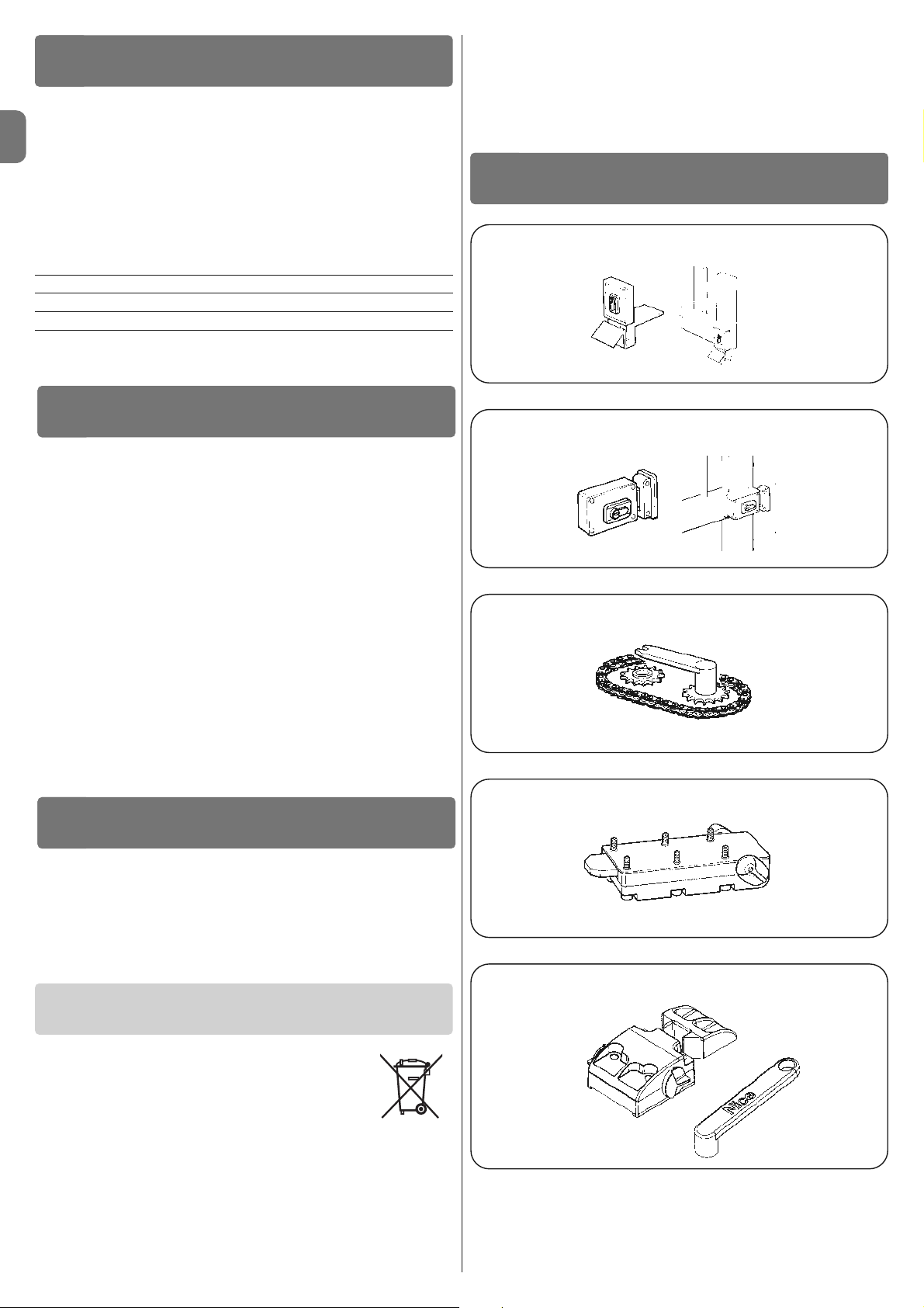
MEA2 Type KEY-Operated Release (fig. 6)
A Pull down the lock cover as shown in the figure.
B Insert the key and rotate it 90° clockwise.
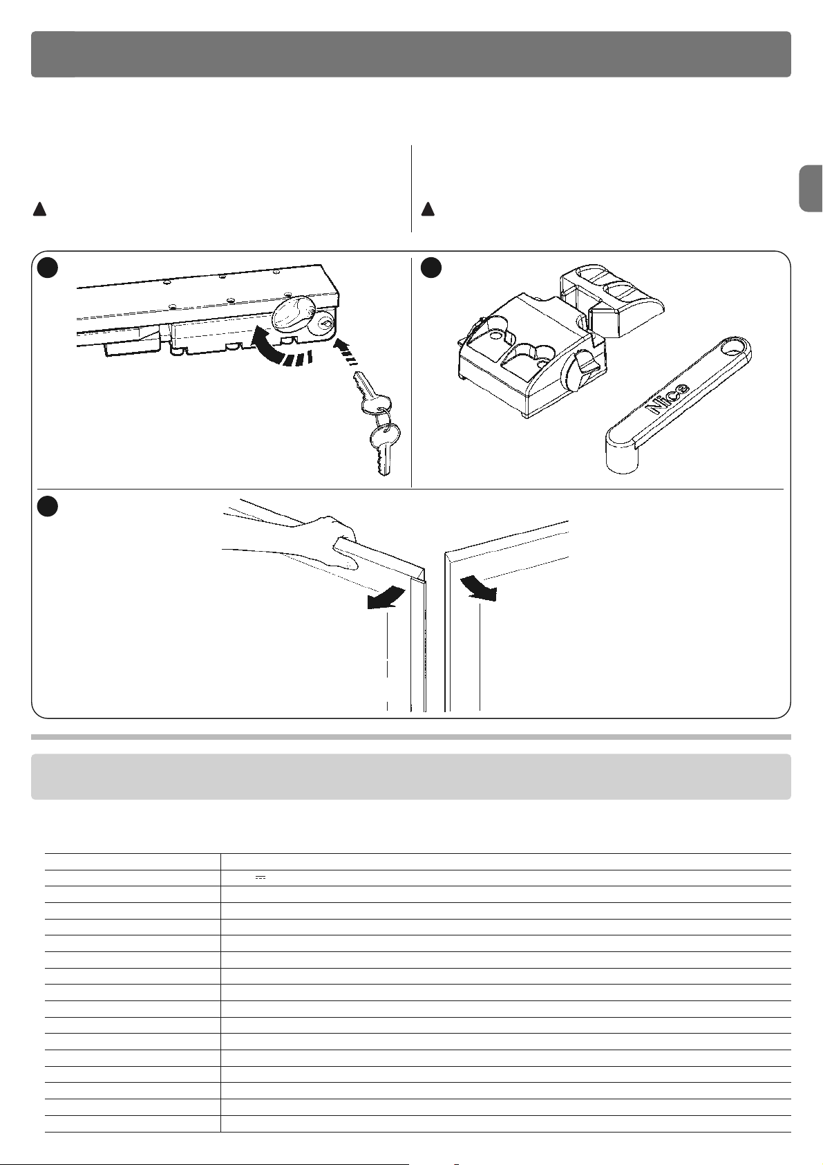
C Move the gate manually (fig. 8).
The system will revert to automatic operation upon the first electrical
manoeuvre.
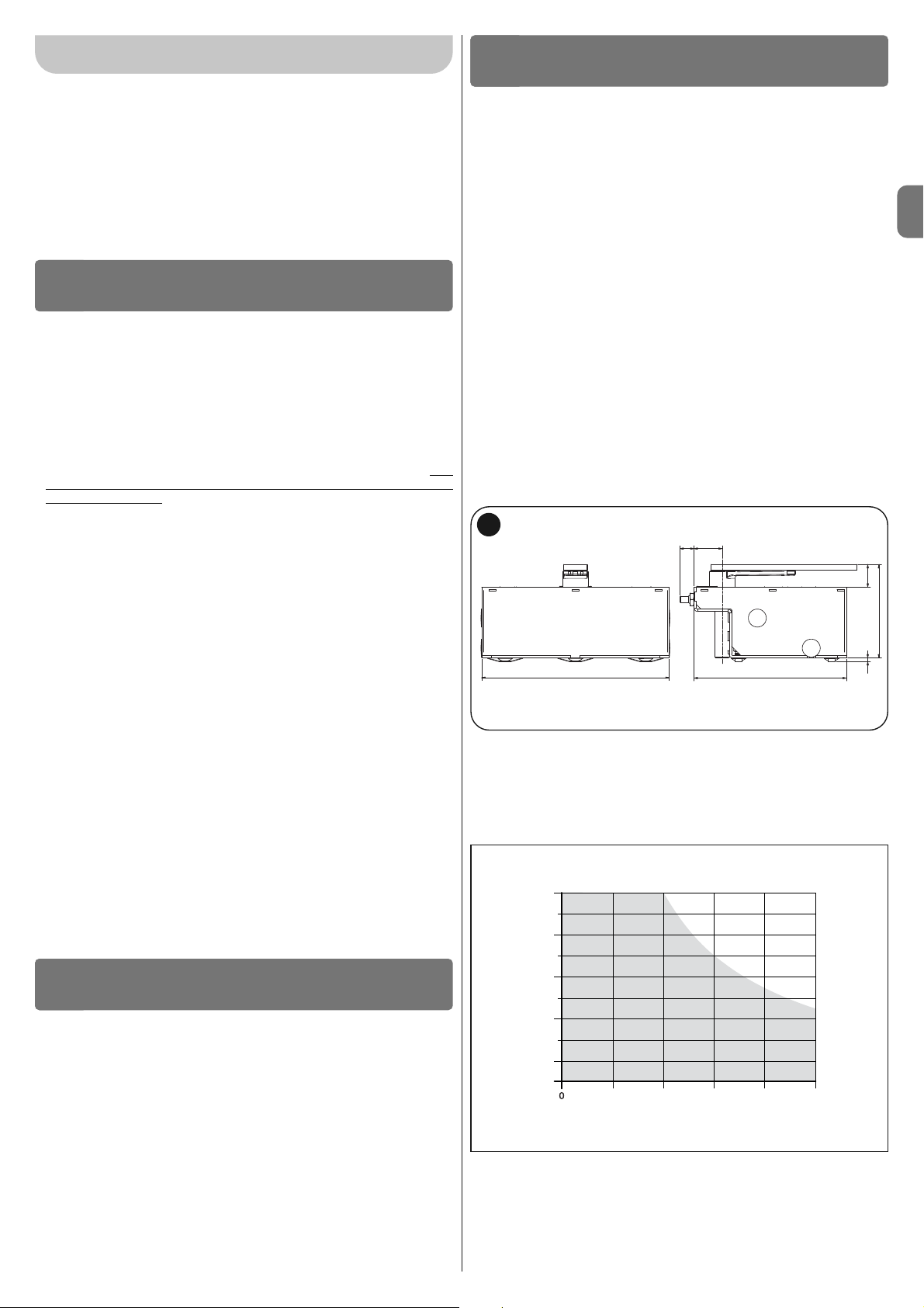
MEA3 Type Lever-Operated Release (fig. 7)
A Pull down the lock cover as shown in the figure.
B Insert the key and rotate it 90° clockwise.
C Move the gate manually (fig. 8).
The system will revert to automatic operation upon the first electrical
manoeuvre.
!
!
RECOMMENDATIONS: • All technical features stated make reference at a room temperature of 20°C (± 5°C). • Nice S.p.a. reserves the right to modify the product at any time it deems necessary, however maintaining the same functionality and destination of use.
■ Type Electro-mechanical dear motors for gates and doors with hinged panels
■ Power input 24 V
■ Peak absorption 7 A
■ Maximum absorption 2 A
■ Potenza di picco 170 W
■ Maximum power 50 W
■ Protection rating IP 67
■ Run from 0° to 110° or 360°
■ Idle speed 0,8 rpm
■ Speed at nominal torque 0,65 rpm
■ Maximum torque 400 Nm
■ Nominal torque 100 Nm
■ Functioning temperature from -20 °C to +50 °C
■ Cycles/hour at the nominal torque 45
■ Duration Estimated between about 100.000 e 250,000 manoeuvre cycles, according to the conditions given in Table 1
■ Dimensions 230 mm x 206 mm x h 88 mm
■ Weight 15 Kg (gear motor with foundation space)
PRODUCT TECHNICAL FEATURES
Perform the manual operation in the event of a power failure or system malfunction.
6
8
7
Page 8

EN
6 – English
CE DECLARATION OF CONFORMITY
and declaration of incorporation of “quasi machinery”
Declaration in accordance with the Directives: 2004/108/EC (EMC); 2006/42/EC (MD) appendix II, part B
Note - The contents of this declaration correspond to declarations in the official document deposited at the registered offices of Nice S.p.a. and in particular to the last revision
available before printing this manual. The text herein has been re-edited for editorial purposes.
A copy of the original declaration can be requested from Nice S.p.a. (TV) I
Number: 389/BM.. Revision: 0 Language: EN
Manufacturer’s Name: NICE s.p.a.
Adress: Via Pezza Alta 13, Z.I. Rustignè, 31046 Oderzo (TV) Italy
Person authorised to draw up
technical documentation: Mr. Oscar Marchetto
Type: “Big Metro” electromechanical gearmotor
Models: BM5024
Accessories:
The undersigned, Luigi Paro, in the role of Managing Director, declares under his sole responsibility, that the product specified above conforms to the provisions of the following directives:
• DIRECTIVE 2004/108/EC OF THE EUROPEAN PARLIAMENT AND COUNCIL of 15 December 2004 regarding the approximation of member state legislation related to electromagnetic compatibility, repealing directive 89/336/EEC, according to the following harmonized standards:
EN 61000-6-2:2005, EN 61000-6-3:2007
Directive 2006/42/EC THE EUROPEAN PARLIAMENT AND COUNCIL of 17 May 2006 regarding machinery and which amends directive 95/16/EC (recasting)
• It is hereby declared that the pertinent technical documentation has been compiled in compliance with appendix VII B of directive 2006/42/EC and that
the following essential requirements have been observed: 1.1- 1.1.2- 1.1.3- 1.2.1-1.2.6- 1.5.1-1.5.2- 1.5.5- 1.5.6- 1.5.7- 1.5.8- 1.5.10- 1.5.11
• The manufacturer undertakes to transmit to the national authorities, in response to a motivated request, all information regarding the “quasi-machine",
while maintaining full rights to the related intellectual property.
• Should the “quasi machine” be put into service in a European country with an official language other than that used in this declaration, the importer is obliged to arrange for the relative translation to accompany this declaration.
• The “quasi-machine” must not be used until the final machine in which it is incorporated is in turn declared as compliant, if applicable, with the provisions
of directive 2006/42/EC.
The product also complies with the following standards:
EN 60335-1:2002 + A1:2004 + A11:2004 + A12:2006 + A2:2006 + A13:2008, EN 60335-2-103:2003
The product also complies, within the constraints of applicable parts, with the following standards:
EN 13241-1:2003, EN 12445:2002, EN 12453:2002, EN 12978:2003
Oderzo, 1 April 2011 Luigi Paro (Managing Director)
Example of the duration calculation of an Big Metro gear motor (refer to
Table 1 and Graph 2):
- panel length: 3 m and panel weight: 500 Kg = fatigue index: 30%
- Installation in windy areas = fatigue index: 15%
- does not have other elements of fatigue
Total fatigue index
= 45%
Estimated duration
= 110.000 manoeuvre cycles
Product duration
The duration and average economic life of the product. The value of duration is
strongly affected by the fatigue index of the manoeuvres performed by the
automation: i.e. the sum of all factors that contribute to wear of the product
(see Table 1).
To establish the probable duration of your automation, proceed as follows:
01. Calculate the fatigue index
by adding the percentage values of the items
present in Table 1;
02. In Graph 2 of the value just found, trace a vertical line that crosses the
curve; from this point trace a horizontal line until the “manoeuvre cycles” line is
crossed. The value determined is the estimated duration
of your product.
The estimation of duration is made on the basis of the design calculations and
the test results performed on prototypes. In fact, as it is an estimate, it does not
represent any guarantee regarding the effective duration of the product.
GRAPH 2
manoeuvre cycles
fatigue index %
Environmental temperature exceeding 40°C or 15 %
below 0°C or humidity exceeding 80%
Blind panel 20 %
Installation in windy area 15 %
Weight of the panel
Fatigue index
< 150 Kg 0 % 10 % 20 % 30 %
150 - 350 Kg 10 % 20 % 30 % 40 %
350 - 550 Kg 20 % 30 % 40 % 50 %
550 - 750 Kg 30 % 40 % 50 % -
750 - 900 Kg 40 % 50 % - -
Length ≤ 2m 2 - 3m 3 - 4m 4 - 5m
of the panel
TABLE 1
250.000
200.000
150.000
100.000
50.000
Page 9

3.1 - Verifiche preliminari all’installazione
Prima di procedere all’installazione, è necessario verificare l’integrità dei componenti del prodotto, l’adeguatezza del modello scelto e l’idoneità dell’ambiente destinato all’installazione.
IMPORTANTE – Il motoriduttore non può automatizzare un cancello ma nuale che non abbia una struttura meccanica efficiente e sicura. Inoltre,
non può risolvere i difetti causati da una sbagliata installazione o da una
cattiva manutenzione del cancello stesso.
3.2 - Idoneità del cancello da automatizzare e dell’ambiente
circostante
• Verificare che la struttura meccanica del cancello sia adatta ad essere auto-
matizzata e conforme alle norme vigenti sul territorio (eventualmente fare riferi-
manto ai dati riportati sull’etichetta del cancello).
• Muovendo manualmente l’anta del cancello in Apertura e in Chiusura, verifi-
care che il movimento avvenga con attrito uguale e costante in ogni punto della corsa (non devono esserci momenti di maggiore sforzo).
• Verificare che l’anta del cancello resti in equilibrio, cioè che non si muova se
portata manualmente in una qualsiasi posizione e lasciata ferma.
• Verificare che lo spazio intorno al motoriduttore consenta di sbloccare ma -
nualmente le ante del cancello, in modo facile e sicuro.
• Prevedere dei fermi di finecorsa a terra sia per l’apertura sia per la chiusura
del cancello.
• Verificare che la zona di fissaggio del motoriduttore sia compatibile con l’in-
gombro di quest’ultimo (fig. 1).
3.3 - Limiti d’impiego del prodotto
Prima di eseguire l’installazione del prodotto, verificare che l’anta del cancello
abbia dimensioni e peso rientranti nei limiti riportati nel grafico 1; valutare
anche le condizioni climatiche (es. vento forte) presenti nel luogo d’installazione,
possono ridurre notevolmente i valori riportati nel grafico.
1
30 60
48
8
200
325400
ITALIANO
Avvertenze per la sicurezza
• ATTENZIONE! – Il presente manuale contiene importanti istruzioni e
avvertenze per la sicurezza delle persone. Un’installazione errata può cau-
sare gravi ferite. Prima di iniziare il lavoro è necessario leggere attentamente
tutte le parti del manuale. In caso di dubbi, sospendere l’installazione e richiedere chiarimenti al Servizio Assistenza Nice.
• ATTENZIONE! – Istruzioni importanti: conservare questo manuale per
eventuali interventi futuri di manutenzione e di smaltimento del prodotto.
• ATTENZIONE! – Secondo la più recente legislazione europea, la realizzazione di una porta o di un cancello automatico deve rispettare le nor
me previste dalla Direttiva 2006/42/CE (ex 98/37/CE) (Direttiva Macchine) e in particolare, le norme EN 12445; EN 12453; EN 12635 e EN
13241-1, che consentono di dichiarare la conformità dell’automazione.
In considerazione di ciò, tutte le operazioni di installazione, di collegamento, di col laudo e di manutenzione del prodotto devono es sere
effettuate es clusivamente da un tecnico qualificato e competente!
Avvertenze per l’installazione
• Prima di iniziare l’installazione verificare se il presente prodotto è adatto ad
automatizzare il vostro cancello o portone (vedere capitolo 3 e le “Caratteristiche tecniche del prodotto”). Se non è adatto, NON procedere all’istallazione.
• Tutte le operazioni di installazione e di manutenzione devono avvenire
con l’automazione scollegata dall’alimentazione elettrica. Se il dispositivo di sconnessione dell’alimentazione non è visibile dal luogo dove è posizionato l’automatismo, prima di iniziare il lavoro è necessario attaccare sul
dispositivo di sconnessione un cartello con la scritta “ATTENZIONE! MANUTENZIONE IN CORSO”.
• Durante l’installazione maneggiare con cura l’automatismo evitando schiacciamenti, urti, cadute o contatto con liquidi di qualsiasi natura. Non mettere il
prodotto vicino a fonti di calore, né esporlo a fiamme libere. Tutte queste azioni possono danneggiarlo ed essere causa di malfunzionamenti o situazioni di
pericolo. Se questo accade, sospendere immediatamente l’installazione e
rivolgersi al Servizio Assistenza Nice.
• Non eseguire modifiche su nessuna parte del prodotto. Operazioni non permesse possono causare solo malfunzionamenti. Il costruttore declina ogni
responsabilità per danni derivanti da modifiche arbitrarie al prodotto.
• Se il cancello o il portone da automatizzare è dotato di una porta pedonale
occorre predisporre l’impianto con un sistema di controllo che inibisca il funzionamento del motore quando la porta pedonale è aperta.
• Il materiale dell’imballo del prodotto deve essere smaltito nel pieno rispetto
della normativa locale.
AVVERTENZE E PRECAUZIONI GE NERALI
PER LA SICUREZZA
1
Il presente prodotto è destinato ad essere utilizzato per automatizzare cancelli o
portoni ad ante battenti.
ATTENZIONE! – Qualsiasi altro uso diverso da quello descritto e in condizioni am bientali diverse da quelle riportate in questo manuale è da considerarsi improprio e vietato!
Il prodotto è un motoriduttore elettromeccanico, provvisto di un motore in corrente continua a 24 V. Il motoriduttore viene alimentato dalla centrale di comando esterna a cui deve essere collegato.
In caso d’interruzione dell’energia elettrica (black-out), è possibile muovere le
ante del cancello sbloccando il motoriduttore con l’apposita chiave; per eseguire la manovra manuale vedere capitolo 8.
Il prodotto è disponibile nella versione
- BM5024 con encoder, adatto per centrali modello MC824H
Non utilizzare i motoriduttori con centrali non compatibili.
DESCRIZIONE DEL PRODOTTO E
DESTINAZIONE D’USO
2
INSTALLAZIONE
3
Italiano – 1
IT
3.4 - Lavori di predisposizione all’installazione
La fig. 2 mostra un esempio di impianto di automatizzazione realizzato con
componenti Nice. Questi componenti sono posizionati se condo uno schema
tipico ed usuale.
Facendo riferimento alla fig. 2, stabilire la posizione approssimativa in cui verrà installato ciascun componente previsto nell’impianto e lo schema di collegamento più appropriato.
GRAFICO 1
PESO MAX ANTA (Kg)
LUNGHEZZA MAX ANTA (m)
900
800
700
600
500
400
300
200
100
12345
Page 10

3.5 - Fissaggio: dimensioni d’ingombro e posizionamento
della cassa di fondazione
1 Eseguire uno scavo di fondazione di dimensioni generose, per collocare la
cassa di fondazione (fig. 3): prevedere una conduttura di scarico per il drenaggio dell’acqua per evitarne il ristagno.
2 Se il cancello dispone di propri arresti meccanici (fig. 2) passare diretta-
mente al punto 3. Altrimenti, Fissare alla cassa l’accessorio per il finecorsa
di apertura (vedi paragrafo 4).
3 Collocare la cassa all’interno dello scavo, con il perno allineato all’asse del-
la cerniera (es. fig. 3).
2 – Italiano
IT
3
1- Cerniera 2- Perno 3- Calcestruzzo
1
2
3
4
5
4
1 Leva di sblocco
2 Leva di collegamento
3 Sfera
4 Staffa di comando
5Perno
2
1 Colonnina per fotocellula. 5 Antenna 9 Elettroserratura verticale
2 Coppia di arresti in apertura 6 Lampeggiante 10 Selettore a chiave o tastiera digitale
3 Linea 230V 7 Fotocellula 11 Scatola di derivazione (non fornita)
4 Quadro di comando (centralina elettrica) 8 Cassa con attuatore BIG METRO
4 Prevedere un condotto per i cavi elettrici ed uno per il drenaggio.
5 Annegare nel calcestruzzo la cassa di fondazione, curandone la messa in
bolla ed il livello.
6 Inserire sul perno della cassa la staffa di comando, avendo cura di interpor-
re la sfera in dotazione (fig. 4).
7 Appoggiare l’anta del cancello sulla leva di sblocco, e fissare con saldatura
robusta.
8 Ingrassare mediante apposito ugello ingrassatore.
Page 11

Italiano – 3
IT
POSIZIONAMENTI DI FINE CORSA
4
3.6 - Installazione del motoriduttore BIG METRO
1 Togliere i dadi e le rondelle indicati nella figura a destra (fig. 5).
2 Collocare il motoriduttore all’ interno della cassa di fondazione assicurando-
si che sia inserito nel verso giusto.
3 Bloccare il motoriduttore con le rondelle e i dadi tolti precedentemente.
4 Collegare con la leva di collegamento (2) il motoriduttore al cancello (fig. 4).
5
Finecorsa di chiusura (in dotazione)
Fissare come mostrato in questa figura
Finecorsa di apertura (in dotazione)
Fissare come mostrato in questa figura
Page 12
IT
4 – Italiano
SMALTIMENTO DEL PRODOTTO
Questo prodotto è parte integrante dell’automazione, e
dunque, deve essere smaltito insieme con essa.
Come per le operazioni d’installazione, anche al termine della
vita di questo prodotto, le operazioni di smantellamento devono essere eseguite da personale qualificato.
Questo prodotto è costituito da vari tipi di materiali: alcuni possono essere riciclati, altri devono essere smaltiti. Informatevi sui sistemi di riciclaggio o smaltimento previsti dai regolamenti vigenti sul vostro territorio, per questa categoria
di prodotto.
Attenzione! – Alcune parti del prodotto possono contenere sostanze inquinanti o pericolose che, se disperse nell’ambiente, potrebbero provocare effetti dannosi sull’ambiente stesso e sulla salute umana.
Come indicato dal simbolo a lato, è vietato gettare questo prodotto nei rifiuti
domestici. Eseguire quindi la “raccolta separata” per lo smaltimento, secondo i
metodi previsti dai regolamenti vigenti sul vostro territorio, oppure riconsegnare
il prodotto al venditore nel momento dell’acquisto di un nuovo prodotto equivalente.
Attenzione! – i regolamenti vigenti a livello locale possono prevedere pesanti
sanzioni in caso di smaltimento abusivo di questo prodotto.
PLA10 Elettroserratura 12 Vca verticale
ACCESSORI A RICHIESTA
8
PLA11 Elettroserratura 12 Vca orizzontale
BMA1 Dispositivo per apertura a 360°
MEA2 Sblocco con serratura
MEA3 Sblocco con apposita leva
Avvertenze:
- Il motoriduttore è fornito con un cavo di alimentazione elettrica lungo 2 m.
Quindi, se si necessita di coprire una distanza maggiore per eseguire i collegamenti elettrici, è necessario utilizzare una scatola di derivazione (non fornita). IMPORTANTE! – È vietato eseguire aggiunte di cavo elettrico all’in-
terno della cassa di fondazione.
- Eseguire i collegamenti elettrici con l’alimentazione di rete scollegata.
Per collegare il cavo di alimentazione alla centrale di comando vedere il manuale di quest’ultima e le seguenti indicazioni:
filo Blu = Alimentazione motore 24 V
filo Marrone =Alimentazione motore 24 V
filo Nero =Encoder
filo Grigio = Encoder
filo Giallo/Verde =Terra
COLLEGAMENTI ELETTRICI
5
Il collaudo dell’intero impianto deve essere eseguito da personale esperto e
qualificato che deve farsi carico delle prove richieste, in funzione del rischio presente.
Per il collaudo di BIG METRO seguire questa procedura:
• chiudere il cancello;
• togliere alimentazione alla centrale;
• sbloccare il motoriduttore dall’anta come indicato nel paragrafo “Sblocco
manuale (sblocco a chiave e a leva) sul capitolo “Istruzioni ed avvertenze destinate all’utilizzatore del motoriduttore BIG METRO;
• aprire manualmente il cancello per tutta la sua corsa;
• verificare che il cancello durante il moto non abbia punti d’attrito;
• verificare che il cancello fermato in qualsiasi punto e sbloccato,non accenni a
muoversi;
• verificare che i sistemi di sicurezza e gli arresti meccanici siano in buono stato;
• verificare che i collegamenti a vite siano ben stretti;
• ripulire l’interno della cassa e verificare che lo scarico dell’acqua funzioni correttemente;
• terminate le verifiche ribloccare il motoriduttore e rialimentare la centrale;
• BIG METRO è sprovvisto di dispositivo di regolazione di coppia, pertanto tale
regolazione è affidata alla centrale di comando;
• misurare la forza d’impatto come previsto dalla normativa EN12453 ed
EN12445.
COLLAUDO E MESSA IN SERVIZIO
6
La manutenzione di BIG METRO non necessita di accorgimenti particolari, ma
un controllo programmato almeno ogni sei mesi permette di ottenere una maggiore vita del motoriduttore ed un corretto e sicuro funzionamento del sistema.
La manutenzione consiste semplicemente nel ripetere la procedura di
collaudo.
MANUTENZIONE DEL PRODOTTO
7
Page 13

Sblocco a CHIAVE tipo MEA2 (fig. 6)
A Abbassare il coperchio copriserratura come indicato in figura.
B Inserire la chiave e ruotarla in senso orario di 90°.
C Agire manualmente sulI’anta (fig. 8).
Il funzionamento automatico avverrà alla prima manovra elettrica.
Sblocco a LEVA tipo MEA3 (fig. 7)
A Abbassare il coperchio copriserratura come indicato in figura.
B Inserire la chiave e ruotarla in senso orario di 90°.
C Agire manualmente sulI’anta (fig. 8).
Il funzionamento automatico avverrà alla prima manovra elettrica.
!
!
IT
Italiano – 5
AVVERTENZE: • Tutte le caratteristiche tecniche riportate, sono riferite ad una temperatura ambientale di 20°C (± 5°C). • Nice S.p.a. si riserva il diritto di appor-
tare modifiche al prodotto in qualsiasi momento lo riterrà necessario, mantenendone comunque la stessa funzionalità e destinazione d’uso.
■ Tipologia Motoriduttore elettromeccanico per cancelli o portoni ad ante battenti
■ Alimentazione 24 V
■ Assorbimento di picco 7 A
■ Assorbimento massimo 2 A
■ Potenza di picco 170 W
■ Potenza massima 50 W
■ Grado di protezione IP 67
■ Corsa da 0° a 110° oppure 360°
■ Velocità a vuoto 0,8 rpm
■ Velocità alla coppia nominale 0,65 rpm
■ Coppia massima 400 Nm
■ Coppia nominale 100 Nm
■ Temperatura di funzionamento da -20 °C a +50 °C
■ Cicli/ora alla coppia nominale 45
■ Durabilità Stimata tra circa 100.000 e 250.000 cicli di manovre, secondo le condizioni riportate nelle Tabella 1
■ Dimensioni 230 mm x 206 mm x h 88 mm
■ Peso 15 Kg (motoriduttore con cassa di fondazione)
CARATTERISTICHE TECNICHE DEL PRODOTTO
SBLOCCO MANUALE DEL MOTORIDUTTORE
9
L’operazione manuale si deve eseguire nel caso di mancanza di corrente o in caso di anomalie dell’impianto.
6
8
7
Page 14

IT
6 – Italiano
DICHIARAZIONE CE DI CONFORMITÀ
e dichiarazione di incorporazione di “quasi macchina”
Dichiarazione in accordo alle Direttive: 2004/108/CE (EMC); 2006/42/CE (MD) allegato II, parte B
Nota - Il contenuto di questa dichiarazione corrisponde a quanto dichiarato nel documento ufficiale depositato presso la sede di Nice S.p.a., e in particolare, alla sua ultima revisione disponibile prima della stampa di questo manuale. Il testo qui presente è stato riadattato per motivi editoriali.
Copia della dichiarazione originale può essere richiesta a Nice S.p.a. (TV) I.
Numero: 389/BM.. Revisione: 0 Lingua: IT
Nome produttore: NICE s.p.a.
Indirizzo: Via Pezza Alta 13, Z.I. Rustignè, 31046 Oderzo (TV) Italia
Persona autorizzata a costituire
la documentazione tecnica: Sig. Oscar Marchetto
Tipo: Motoriduttore elettromeccanico “Big Metro”
Modelli: BM5024
Accessori:
Il sottoscritto Luigi Paro in qualità di Amministratore Delegato, dichiara sotto la propria responsabilità che il prodotto sopra indicato risulta conforme alle
disposizioni imposte dalle seguenti direttive:
• DIRETTIVA 2004/108/CE DEL PARLAMENTO EUROPEO E DEL CONSIGLIO del 15 dicembre 2004 concernente il ravvicinamento delle legislazioni degli
Stati membri relative alla compatibilità elettromagnetica e che abroga la direttiva 89/336/CEE, secondo le seguenti norme armonizzate:
EN 61000-6-2:2005, EN 61000-6-3:2007
Direttiva 2006/42/CE DEL PARLAMENTO EUROPEO E DEL CONSIGLIO del 17 maggio 2006 relativa alle macchine e che modifica la direttiva 95/16/CE
(rifusione)
• Si dichiara che la documentazione tecnica pertinente è stata compilata in conformità all’allegato VII B della direttiva 2006/42/CE e che sono stati rispettati i seguenti requisiti essenziali: 1.1- 1.1.2- 1.1.3- 1.2.1-1.2.6- 1.5.1-1.5.2- 1.5.5- 1.5.6- 1.5.7- 1.5.8- 1.5.10- 1.5.11
• Il produttore si impegna a trasmettere alle autorità nazionali, in risposta ad una motivata richiesta, le informazioni pertinenti sulla “quasi macchina”, mantenendo impregiudicati i propri diritti di proprietà intellettuale.
• Qualora la “quasi macchina” sia messa in servizio in un paese europeo con lingua ufficiale diversa da quella usata nella presente dichiarazione, l’importatore ha l’obbligo di associare alla presente dichiarazione la relativa traduzione.
• Si avverte che la “quasi macchina” non dovrà essere messa in servizio finché la macchina finale in cui sarà incorporata non sarà a sua volta dichiarata
conforme, se del caso, alle disposizioni della direttiva 2006/42/CE.
Inoltre il prodotto risulta conforme alle seguenti norme:
EN 60335-1:2002 + A1:2004 + A11:2004 + A12:2006 + A2:2006 + A13:2008, EN 60335-2-103:2003
Il prodotto risulta conforme, limitatamente alle parti applicabili, alle seguenti norme:
EN 13241-1:2003, EN 12445:2002, EN 12453:2002, EN 12978:2003
Oderzo, 1 aprile 2011 Luigi Paro (Amministratore Delegato)
GRAFICO 2
cicli di manovre
indice di gravosità %
Esempio del calcolo di durabilità di un motoriduttore Big Metro (fare riferimento alla Tabella 1 e al Grafico 2):
- lunghezza dell’anta: 3 m e peso dell’anta: 500 Kg = indice di gravosità: 30%
- Installazione in zone ventose = indice di gravosità: 15%
- non presenti altri elementi di affaticamento
Indice di gravosità totale = 45%
Durabilità stimata
= 110.000 cicli di manovre
Durabilità del prodotto
La durabilità è la vita economica media del prodotto. Il valore della durabilità è
fortemente influenzato dall’indice di gravosità delle manovre eseguite dall’automatismo: cioè la somma di tutti i fattori che contribuiscono all’usura del prodotto (vedere Tabella 1).
Per stabilire la durabilità probabile del vostro automatismo procedere nel modo
seguente:
01. Calcolare l’indice di gravosità
sommmando tra loro i valori in percentuale
delle voci presenti nella Tabella 1;
02. Nel Grafico 2 dal valore appena trovato, tracciare una linea verticale fino ad
incrociare la curva; da questo punto tracciare una linea orizzontale fino ad
incrociare la linea dei “cicli di manovre”. Il valore determinato è la durabilità sti
-
mata del vostro prodotto.
La stima di durabilità viene effettuata sulla base dei calcoli progettuali e dei risultati di prove effettuate su prototipi. Infatti, essendo una stima, non rappresenta
alcuna garanzia sull’effettiva durata del prodotto.
Temperatura ambientale superiore a 40°C o 15 %
inferiore a 0°C o umidità superiore all’80%
Anta cieca 20 %
Installazione in zona ventosa 15 %
Peso dell’anta
Indice di gravosità
< 150 Kg 0 % 10 % 20 % 30 %
150 - 350 Kg 10 % 20 % 30 % 40 %
350 - 550 Kg 20 % 30 % 40 % 50 %
550 - 750 Kg 30 % 40 % 50 % -
750 - 900 Kg 40 % 50 % - -
Lunghezza ≤ 2m 2 - 3m 3 - 4m 4 - 5m
dell’anta
TABELLA 1
250.000
200.000
150.000
100.000
50.000
Page 15
FR
Français – 1
FRANÇAIS
Mises en garde de sécurité
• ATTENTION ! – Ce manuel contient d’importantes instructions et mises
en garde pour la sécurité des personnes. Une installation incorrecte peut
provoquer de graves blessures. Avant de commencer le travail, il faut lire
attentivement tout le manuel. En cas de doutes, suspendre l’installation et
demander des éclaircissements au Service d’Assistance Nice.
• ATTENTION ! – Instructions importantes : conserver ce manuel pour toute future intervention de maintenance et d’élimination du produit.
• ATTENTION ! – Conformément à la législation européenne la plus
récente, la réalisation d’une porte ou d’un portail automatique doit
respecter les normes prévues par la Directive 2006/42/CE (ex 98/37/CE)
(Directive Machines) et en particulier, les normes EN 12445 ; EN 12453 ;
EN 12635 et EN 13241-1, qui permettent de déclarer la conformité de
l’automatisation. Par conséquent, toutes les opérations d’installation,
de raccordement, de test et de maintenance du produit doivent être
effectuées exclusivement par un technicien qualifié et compétent !
Mises en garde au sujet de l’installation
• Avant de commencer l’installation, vérifier si ce produit est adéquat pour automatiser votre portail ou votre porte (voir chapitre 3 et les “Caractéristiques
techniques du produit”). S’il n’est pas adéquat, NE PAS procéder à l’installation.
• Toutes les opérations d’installation et de maintenance doivent s’effec-
tuer quand l’automatisation est débranchée de l’alimentation électrique. Si le dispositif de coupure de l’alimentation n’est pas visible du lieu où
est situé l’automatisme, avant de commencer le travail, il faut poser sur le
dispositif de déconnexion un panneau portant le texte "ATTENTION ! MAINTENANCE EN COURS”.
• Au cours de l’installation, manipuler soigneusement l’automatisme et éviter tout
écrasement, choc, chute ou contact avec des liquides de n’importe quelle sorte. Ne pas mettre le produit à proximité de sources de chaleur ni l’exposer à des
flammes vives. Toutes ces actions peuvent l’endommager et causer des dysfonctionnements ou des situations de danger. Si c’était le cas, suspendre immédiatement l’installation et s’adresser au Service d’Assistance Nice.
• Ne modifier aucune partie du produit. Des opérations non autorisées ne peuvent
causer que des dysfonctionnements. Le fabricant décline toute responsabilité
quant aux dommages provoqués par des modifications arbitraires du produit.
• Si le portail ou la porte à automatiser est équipé d’une porte piétonnière, il
faut doter l’installation d’un système de contrôle qui empêche le fonctionnement du moteur quand la porte piétonnière est ouverte.
• Le matériel de l’emballage du produit doit être éliminé en respectant pleinement les normes locales.
MISES EN GARDE ET PRÉCAUTIONS
GÉNÉRALES DE SÉCURITÉ
1
Le présent produit est destiné à être utilisé pour automatiser des portails ou
des portes battantes à vantaux.
ATTENTION ! – Toute utilisation autre que celle décrite et dans des conditions ambiantes différentes de celles indiquées dans ce manuel doit
être considérée impropre et interdite !
Le produit est un motoréducteur électromécanique, doté d’un moteur en courant continu 24 V. Le motoréducteur est alimenté par la centrale de commande
externe à laquelle il doit être raccordé.
En cas de coupure de l’énergie électrique (black-out), il est possible de déplacer le
vantail du portail en débloquant le motoréducteur à l’aide de la clé prévue ; pour
effectuer la manœuvre manuelle, voir chapitre 8.
Il produit est disponible dans la version
- BM5024 avec encodeur, adapté aux centrales modèle MC824H
Ne pas utiliser les motoréducteurs avec des centrales qui ne seraient pas
compatibles.
DESCRIPTION DU PRODUIT
ET DESTINATION
2
3.1 - Vérifications préalables à l’installation
Avant de procéder à l’installation, il faut vérifier le bon état des composants du
produit, la conformité du modèle choisi et l’adéquation du local destiné à l’installation.
IMPORTANT – Le motoréducteur ne peut pas automatiser un portail ma nuel qui ne serait pas doté d’une structure mécanique efficace et sûre. Il
ne peut pas non plus résoudre les défauts causés par une installation
erronée ou par une mauvaise maintenance du portail.
3.2 - Adéquation du portail à automatiser et du milieu
environnant
• Vérifier que la structure mécanique du portail soit adéquate pour être auto-
matisée et conforme aux normes en vigueur sur le territoire (consulter éventuel-
lement les données reprises sur l’étiquette du portail).
• En déplaçant manuellement le vantail du portail en Ouverture et en Fermeture,
vérifier que le mouvement ait lieu avec un frottement égal et constant en chaque
point de la course (il ne doit pas y avoir de moments de plus grand effort).
• Vérifier que le vantail du portail reste en équilibre, c’est-à-dire qu’il ne bouge pas
s’il est situé manuellement dans une position quelconque et laissé immobile.
• Vérifier que l’espace autour du motoréducteur permette de débloquer ma -
nuellement les vantaux du portail, de façon aisée et sûre.
• Prévoir des arrêtoirs de fin de course au sol tant pour l’ouverture que pour la
fermeture du portail.
• Vérifier que la zone de fixation du motoréducteur soit compatible avec les
dimensions de ce dernier (fig. 1).
3.3 - Limites d’utilisation du produit
Avant d’installer le produit, vérifier que le vantail du portail présente des dimensions
et un poids compris dans les limites reprises au graphique 1; évaluer aussi les
conditions climatiques (ex. vent fort) existantes dans le lieu d’installation, elles peuvent réduire considérablement les valeurs reprises sur le graphique.
INSTALLATION
3
GRAPHIQUE 1
3.4 - Travaux de pré-installation
La fig. 2 montre un exemple d’installation d’automatisation exécutée avec des composants Nice. Ces composants sont placés selon un schéma typique et habituel.
En se basant sur la fig. 2, définir la position approximative où sera installé
chaque composant prévu sur l’installation ainsi que le schéma de raccordement le plus approprié.
POIDS MAX VANTAIL (Kg)
LONGUEUR MAX VANTAIL (m)
1
30 60
48
8
200
325400
900
800
700
600
500
400
300
200
100
12345
Page 16

FR
2 – Français
3.5 -Fixation : Dimensions d’encombrement et positionnement de la caisse de fondation
1 Creuser un trou de grandes dimensions pour y placer le caisson de fonda-
tion (fig. 3) : prévoir un conduit de drainage de l’eau pour éviter toute stagnation.
2 Si le portail dispose de ses butées mécaniques (fig. 3) passer directement
au point 3. A défaut de butées, fixer au caisson l’accessoire de fin de course d’ouverture (voir paragraphe 4).
3 Placer la caisse à l’intérieur du trou avec le pivot aligné avec l’axe de la
charnière (fig. 3);
3
1- Charnière 2- Pivot 3- Béton
1
2
3
4
5
4
Levier de débrayage
2 Levier de raccordement
3 Bille
4 Étrier de commande
5 Pivot
2
4 Prévoir un conduit pour les câbles électriques et un autre pour le drainage;
5 Noyer dans le béton la caisse de fondation en vérifiant sa mise à niveau;
6 Positionner sur le pivot de la caisse le etrier de commande en veillant à
interposer la bille fournie (fig. 4);
7 Poser la battant du portail sur le levier de débrayage et fixer avec une sou-
dure robuste;
8 Graisser au moyen de la buse de graissage.
1 Colonnette pour photocellule 5 Antenne 9 Serrure électrique
2 Couple d’arrêts en ouverture 6 Clignotant 10 Sélecteur à clef ou clavier numérique
3 Ligne 230 V 7 Photocellule 11 Boîte de dérivation (non fournie)
4 Armoire de commande (armoire électrique)) 8 Caisse avec opérateur BIG METRO
Page 17

FR
Français – 3
POSITIONNEMENT DES FINS DE COURSE
4
3.6 - Installation de l’opérateur BIG METRO
1 Enlever les écrous et les rondelles indiqués sur la figure de droite (fig. 5).
2 Placer l’opérateur à l’intérieur de la caisse de fondation en veillant à le posi-
tionner dans le bon sens.
3 Bloquer l’opérateur avec les rondelles et les écrous enlevés précédem-
ment.
4 Raccorder l’opérateur au portail avec le levier de raccordement (2) (fig. 4).
5
Fin de course de fermeture (fourni
avec le moteur), fixer comme indiqué
sur la figure
Fin de course de ouverture (fourni
avec le moteur), fixer comme indiqué
sur la figure
Page 18

FR
4 – Français
ÉLIMINATION DU PRODUIT
Ce produit est partie intégrante de l’automatisation et doit
donc être éliminé avec celle-ci.
Comme pour les opérations d’installation, même à la fin de la
vie de ce produit, les opérations de démantèlement doivent
être effectuées par un personnel qualifié.
Ce produit est composé de différents types de matériaux : certains peuvent
être recyclés, d’autres doivent être éliminés. S’informer sur les systèmes de
recycla ge ou de mise au rebut prévus par les règlements en vigueur sur le territoire, pour cette catégorie de produit.
Attention ! – Certaines parties du produit peuvent contenir des substances
polluantes ou dangereuses qui, si dispersées dans l’environnement, pourraient
provoquer des effets nocifs sur l’environnement et sur la santé humaine.
Comme indiqué par le symbole ci-contre, il est interdit de jeter ce produit dans
PLA10 Serrure électrique 12 Vca verticale
ACCESSOIRES SUR DEMANDE
8
PLA11 Serrure électrique 12 Vca horizontale
BMA1 Dispositif pour ouverture à 360°
MEA2 Débrayage à serrure
MEA3 Débrayage à levier
Mises en garde :
- Le motoréducteur est doté d’un câble d’alimentation électrique d’une lon-
gueur de 2 m. Par conséquent, s’il fallait couvrir une distance supérieure pour
effectuer les connexions électriques, il faudra utiliser une boîte de dérivation
(non fournie). IMPORTANT ! – Il est interdit d’effectuer des ajouts de
câble électrique à l’intérieur de la caisse de fondation.
- Effectuer les raccordements électriques après avoir débranché l’ali-
mentation de secteur.
Pour connecter le câble d’alimentation à la centrale de commande, consulter le
manuel de la centrale et les indications suivantes :
fil Bleu =Alimentation moteur 24 V
fil Marron = Alimentation moteur 24 V
fil Noir =Encodeur
fil Gris =Encodeur
fil Jaune/Vert =Terre
RACCORDEMENTS ÉLECTRIQUES
5
L’essai de toute l’installation doit être effectuée par du personnel qualifié et
expérimenté qui devra se charger d’établir les essais prévus en fonction des
risques présents. Pour l’essai de BIG METRO, suivre cette procédure:
• fermer le portail;
• couper l’alimentation sur la logique de commande;
• Débrayer l’opérateur en libérant le battant comme l’indique le paragraphe
“Débrayage manuel (débrayage avec clé et levier)” dans le chapitre “Instructions et recommandations destinées à l’utilisateur de l’opérateur BIG
METRO”.
• ouvrir manuellement le portail sur toute sa course;
• vérifier que le portail ne présente pas de points de frottement durant le mou-
vement;
• vérifier que le portail arrêté dans n’importe quelle position et débrayé n’a pas
tendance à se déplacer;
• vérifier que les systèmes de sécurité et les arrêts mécaniques sont en bon
état;
• vérifier que les raccordements à vis sont bien serrés;
• nettoyer l’intérieur de la caisse et vérifier que l’évacuation de l’eau fonctionne
correctement;
• quand les vérifications sont terminées, rebloquer l’opérateur et réalimenter la
logique de commande;
• BIG METRO n’est pas équipé du dispositif de réglage du couple, ce réglage
est donc assuré par la logique de commande;
• Mesurer la force d’impact comme le prévoit la règlementation EN12453 et
EN12445.
TEST ET MISE EN SERVICE
6
La maintenance de BIG METRO ne requiert pas d’opérations particulières mais
un contrôle programmé au moins tous les six mois permet de garantir à l’opérateur une plus longue durée et d’assurer un fonctionnement correct et sûr du
système.
La maintenance consiste simplement à répéter la procédure de contrôle.
MAINTENANCE DU PRODUIT
7
les déchets domestiques. Effectuer une “collecte séparée” pour la mise au
rebut, selon les méthodes prévues par les règlements en vigueur sur le territoire, ou amener le produit au vendeur au moment de l’achat d’un nouveau
produit équivalent.
Attention ! – les règlements en vigueur au niveau local peuvent prévoir de
lourdes sanctions en cas de mise au rebut abusif de ce produit.
Page 19
FR
Français – 5
aMISES EN GARDE : • Toutes les caractéristiques techniques reprises se réfèrent à une température ambiante de 20°C (± 5°C). • Nice S.p.a. se réserve le droit
d’apporter des modifications au produit à chaque fois qu’elle le jugera nécessaire, tout en conservant cependant ses fonctions et sa destination d’usage.
■ Type Motoréducteur électromécanique pour portails ou portes battantes à vantaux
■ Alimentation 24 V
■ Absorption de pic 7 A
■ Absorption maximale 2 A
■ Puissance de pic 170 W
■ Puissance maximale 50 W
■ Degré de protection IP 67
■ Course de 0° à 110° ou de 360°
■ Vitesse à vide 0,8 rpm
■ Vitesse au couple nominal 0,65 rpm
■ Couple maximum 400 Nm
■ Couple nominal 100 Nm
■ Température de fonctionnement de -20 °C à +50 °C
■ Cycles/heure au couple nominal 45
■ Durabilité Estimée entre 100.000 et 250.000 cycles de manœuvres environ, selon les conditions reprises au Tableau 1
■ Dimensions 230 mm x 206 mm x h 88 mm
■ Poids 15 Kg (motoréducteur avec caisse de fondation)
CARACTÉRISTIQUES TECHNIQUES DU PRODUIT
Débrayage à CLÉ type MEA2 (fig. 6)
A Abaisser le couvercle de la serrure comme indiqué sur la figure.
B Introduire la clef et la tourner de 90° dans le sens des aiguilles d’une montre.
C Agir manuellement sur le battant (fig. 8).
Le fonctionnement automatique aura lieu lors de la première manœuvre
électrique.
Débrayage à levier type MEA3 (fig. 7)
A Abaisser le couvercle de la serrure comme indiqué sur la figure.
B Introduire la clef et la tourner de 90° dans le sens des aiguilles d’une montre.
C Agir manuellement sur le battant (fig. 8).
Le fonctionnement automatique aura lieu lors de la première manœuvre
électrique.
!
!
Manœuvre manuelle (débrayage à clé et à levier)
L’opération manuelle doit être utilisée en cas de panne de courant ou d’anomalie de l’installation.
DÉBRAYER MANUELLEMENT L’OPÉRATEUR
9
6
8
7
Page 20

FR
6 – Français
DÉCLARATION CE DE CONFORMITÉ
et déclaration d’incorporation de « quasi-machine »
Déclaration conformément aux Directives : 2004/108/CE (EMC) ; 2006/42/CE (DM) annexe II, partie B
Note - Le contenu de cette déclaration de conformité correspond à ce qui est déclaré dans le document officiel, déposé au siège de Nice S.p.a., et en particulier à sa dernière révision disponible avant l'impression de ce guide. Ce texte a été réadapté pour des raisons d'édition. Une copie de la déclaration originale peut être demandée à Nice S.p.a. (TV) I.
Numéro : 389/BM.. Révision : 0 Langue : FR
Nom producteur : NICE s.p.a.
Adresse : Via Pezza Alta 13, Z.I. Rustignè, 31046 Oderzo (TV) Italie
Personne autorisée à constituer
la documentation technique : M. Oscar Marchetto
Type : Opérateur électromécanique « Big Metro »
Modèles : BM5024
Accessoires :
Je soussigné Luigi Paro en qualité d’Administrateur Délégué, déclare sous mon entière responsabilité que le produit susmentionné est conforme aux dispositions imposées par les directives suivantes :
• DIRECTIVE 2004/108/CE DU PARLEMENT EUROPÉEN ET DU CONSEIL du 15 décembre 2004 concernant le rapprochement des législations des États
membres relatives à la compatibilité électromagnétique et qui abroge la directive 89/336/CEE, selon les normes harmonisées suivantes :
EN 61000-6-2:2005, EN 61000-6-3:2007
Directive 2006/42/CE DU PARLEMENT EUROPÉEN ET DU CONSEIL du 17 mai 2006 relative aux machines et qui modifie la directive 95/16/CE (refonte)
• Nous déclarons que la documentation technique pertinente a été remplie conformément à l’annexe VII B de la directive 2006/42/CE et que les conditions
essentielles suivantes ont été respectées : 1.1- 1.1.2- 1.1.3- 1.2.1-1.2.6- 1.5.1-1.5.2- 1.5.5- 1.5.6- 1.5.7- 1.5.8- 1.5.10- 1.5.11
• Le producteur s’engage à transmettre aux autorités nationales, suite à une demande dûment motivée, les informations pertinentes sur la « quasi-machine
», sans que cela porte préjudice à ses droits de propriété intellectuelle.
• Si la « quasi-machine » est mise en service dans un pays européen avec une langue officielle différente utilisée dans la présente déclaration, l’importateur
a l’obligation d’associer à la présente déclaration la traduction correspondante.
• Il est précisé que la quasi-machine ne doit pas être mise en service tant que la machine finale dans laquelle elle doit être incorporée n’a pas été elle-même
déclarée conforme aux dispositions pertinentes de la directive 2006/42/CE.
De plus, le produit est conforme aux normes suivantes :
EN 60335-1:2002 + A1:2004 + A11:2004 + A12:2006 + A2:2006 + A13:2008, EN 60335-2-103:2003
Le produit est conforme, pour ce qui est des seules parties applicables, aux normes suivantes :
EN 13241-1:2003, EN 12445:2002, EN 12453:2002, EN 12978:2003
Oderzo, 1
er
Avril 2011 Luigi Paro (Administrateur Délégué)
Exemple du calcul de durabilité d’un motoréducteur Big Metro (se référer
au Tableau 1 et au Graphique 2):
- longueur du vantail : 3 m et poids du vantail : 500 Kg = indice de pénibilité : 30%
- Installation dans des zones venteuses = indice de pénibilité : 15%
- non présents d’autres éléments de fatigue
Indice de pénibilité totale
= 45%
Durabilité estimée
= 110.000 cicli di manovre
Durabilité du produit
La durabilité représente la vie économique moyenne du produit. La valeur de la
durabilité est fortement influencée par l’indice de la pénibilité des manœuvres
effectuées par l’automatisme : c’est-à-dire la somme de tous les facteurs qui
contribuent à l’usure du produit (voir Tableau 1).
Pour établir la durabilité probable de votre automatise, procéder de la façon
suivante :
01. Calculer l’indice de pénibilité
en additionnant entre elles les valeurs en pour-
centage des entrées présentes sur le Tableau 1;
02. Sur le Graphique 2 à partir de la valeur que l’on vient de trouver, tracer une
ligne verticale jusqu’à croiser la courbe ; ensuite tracer une ligne horizontale
jusqu’à croiser la ligne des “cycles de manœuvres”. La valeur déterminée
représente la durabilité estimée
de votre produit.
L’estimation de durabilité s’effectue sur la base des calculs conceptuels et des
résultats de tests effectués sur prototypes. Étant donné qu’il s’agit en effet d’une
estimation, elle ne constitue aucune garantie sur la durée effective du produit.
GRAPHIQUE 2
cycles de manœuvres
indice de pénibilité %
Température ambiante supérieure à 40°C ou 15 %
inférieure à 0°C ou humidité supérieure à 80%
Vantail plein 20 %
Installation dans une zone venteuse 15 %
Poids du vantail
Indice de pénibilité
< 150 Kg 0 % 10 % 20 % 30 %
150 - 350 Kg 10 % 20 % 30 % 40 %
350 - 550 Kg 20 % 30 % 40 % 50 %
550 - 750 Kg 30 % 40 % 50 % -
750 - 900 Kg 40 % 50 % - -
Longueur ≤ 2m 2 - 3m 3 - 4m 4 - 5m
du vantail
TABLEAU 1
250.000
200.000
150.000
100.000
50.000
Page 21

ES
Español – 1
ESPAÑOL
Advertencias para la seguridad
• ¡ATENCIÓN! – Este manual recoge instrucciones y advertencias importantes para la seguridad de las personas. Una instalación incorrecta pue-
de provocar lesiones graves. Antes de iniciar el trabajo es necesario leer con
atención todas las secciones del manual. En caso de duda, interrumpa la instalación y pida aclaraciones al Servicio de asistencia Nice.
• ¡ATENCIÓN! – Instrucciones importantes: conserve este manual para
posibles intervenciones de mantenimiento y de eliminación del producto
en el futuro.
• ¡ATENCIÓN! – Según la más reciente legislación europea, la realización de
una puerta o de una cancela automátic debe respetar las normas previs
tas por la Directiva 2006/42/CE (ex 98/37/CE) (Directiva Máquinas) y especialmente, las normas EN 12445, EN 12453, EN 12635 y EN 13241-1, que
permiten declarar la conformidad del automatismo. Considerando lo
antes mencionado, todas las operaciones de instalación, de conexión,
de inspección y pruebas y de mantenimiento del producto las debe realizar exclusivamente un técnico calificado y competente.
Advertencias para la instalación
• Antes de iniciar la instalación compruebe si este producto es apto para automatizar su cancela o portal (véase el capítulo 3 y las "Características técnicas
del producto”). Si no es apto, NO lo instale.
• Todas las operaciones de instalación y de mantenimiento se deben rea-
lizar con el automatismo desconectado de la corriente eléctrica. Si el
dispositivo de desconexión de la corriente no se ve desde el lugar donde
está el automatismo, antes de iniciar el trabajo es necesario posicionar en el
dispositivo de desconexión un cartel con el letrero "¡ATENCIÓN! MANTENIMIENTO EN CURSO".
• Durante la instalación, manipule el automatismo con cuidado evitando aplastamientos, golpes, caídas o contacto con líquidos de cualquier naturaleza.
No ponga el producto cerca de fuentes de calor ni lo exponga a llamas abiertas. El hacerlo podría estropearlo y causar problemas de funcionamiento o
situaciones de peligro. Si esto ocurre, interrumpa de inmediato la instalación
y pida ayuda al Servicio de asistencia Nice.
• No modifique ninguna de las partes del producto. Cualquier operación no admitida puede provocar problemas de funcionamiento. El fabricante declina toda
responsabilidad por daños causados por modificaciones arbitrarias al producto.
• Si la cancela o el portal que se van a automatizar cuentan con una puerta
peatonal, se le debe incorporar a la instalación un sistema de control, que
inactive el funcionamiento del motor cuando la puerta peatonal esté abierta.
• El material del embalaje del producto debe eliminarse respetando plenamente las normativas locales.
ADVERTENCIAS Y PRECAUCIONES
GENERALES PARA LA SEGURIDAD
1
Este producto está destinado a ser usado para automatizar cancelas o portales de hojas batientes.
¡ATENCIÓN! – ¡Cualquier uso diferente del uso descrito y en condiciones
ambientales diferentes de las indicadas en este manual debe considerarse impropio y prohibido!
El producto es un motorreductor electromecánico, con un motor de corriente
continua de 24 V. El motorreductor se alimenta desde la central de mando
externa a la que se debe conectar.
En caso de interrupción de la energía eléctrica (black-out),es posible mover las
hojas de la cancela desbloqueando el motorreductor con la llave apropiada;
para la maniobra manual véase la sección 8.
El producto está disponible en la versión
- BM5024 con encoder, adecuado para centrales modelo MC824H
No utilice los motorreductores con centrales no compatibles.
DESCRIPCIÓN DEL PRODUCTO
Y DESTINACIÓN DE USO
2
3.1 - Controles previos a la instalación
Antes de efectuar la instalación, es necesario comprobar que los componentes
del producto estén en perfectas condiciones, que el modelo elegido sea adecuado y que el ambiente destinado a la instalación sea idóneo.
IMPORTANTE – El motorreductor no puede automatizar una cancela
manual que no tenga una estructura mecánica eficiente y segura. Además, no puede solucionar los defectos causados por una instalación
errónea o un mantenimiento incorrecto de la misma.
3.2 - Idoneidad de la cancela que se va a automatizar y del
ambiente circundante
• Controle que la estructura mecánica de la cancela se pueda automatizar y
esté en conformidad con las normas vigentes en el territorio (eventualmente
consulte los datos reproducidos en la etiqueta de la cancela).
• Moviendo manualmente la hoja de la cancela en Apertura y en Cierre, contro-
le que el movimiento tenga lugar con una fricción igual y constante en todos los
puntos del movimiento (no deben haber momentos de mayor esfuerzo).
• Controle que la hoja de la cancela se mantenga en equilibrio, es decir, que no
se mueva si se desplaza manualmente a cualquier posición y se deja detenida.
• Controle que el espacio alrededor del motorreductor permita desbloquear
manualmente las hojas de la cancela, de manera fácil y segura.
• Posicione topes de fin de carrera en el suelo, tanto para la apertura como
para el cierre de la cancela.
• Controle que la zona de fijación del motorreductor sea compatible con las
dimensiones globales del mismo (fig. 1).
3.3 - Límites de uso del producto
Antes de instalar el producto, controle que las dimensiones y el peso de la hoja de la
cancela estén dentro de los límites que se muestran en el gráfico 1; evalúe también
las condiciones climáticas (ej. viento fuerte) presentes en el lugar de la instalación, ya
que pueden reducir considerablemente los valores mostrados en el gráfico.
INSTALACIÓN
3
GRÁFICO 1
3.4 - Trabajos de preparación para la instalación
La fig. 2 muestra un ejemplo de instalación de automatización realizado con com-
ponentes Nice. Estos componentes se posicionan según un esquema típico y usual.
Consultando la fig. 2, establezca la posición aproximativa en la que se instalará cada componente previsto en la instalación, y el esquema de conexión
más apropiado.
PESO MÁX. DE LA HOJA (Kg)
LONGITUD MÁX. DE LA HOJA (m)
1
30 60
48
8
200
325400
900
800
700
600
500
400
300
200
100
12345
Page 22

ES
2 – Español
3.5 - Fijación: Medidas y colocación de la caja de cimentación
1 Realice un pozo de cimentación de dimensiones amplias para colocar la
caja de cimentación (fig. 3): instale una tubería de desagüe para el drenaje
del agua a fin de evitar el estancamiento.
2 Si la puerta incorporara sus finales de carrera mecánicos (fig. 2), pase
directamente al punto 3. En caso contrario, fije a la caja el accesorio para el
final de carrera de apertura (véase el apartado 4).
3 Coloque la caja adentro de la excavación, con el perno alineado con el eje
de la bisagra (fig. 3).
3
1- Gozne 2- Perno 3- Hormigón
1
2
3
4
5
4
1 Palanca de desbloqueo
2 Palanca de conexión
3 Bola
4 Brida de mando
5Pern
2
1 Columna para fotocélula 5 Antena 9 Electrocerradura vertical
2 Par de topes de apertura 6 Luz intermitente 10 Selector de llave o teclado digital
3 Línea 230V 7 Fotocélula 11 Caja de derivación (no suministrada)
4 Cuadro de mando (central eléctrica) 8 Caja con actuador BIG METRO
4 Haga llegar un tubo para que pasen los cables eléctricos y uno para el dre-
naje.
5 Sumerja en el hormigón la caja de cimentación, nivelándola correctamente.
6 Introduzca en el perno de la caja la brida de mando, interponiendo la bola
suministrada (fig. 4).
7 Apoye la hoja de la puerta sobre la palanca de desbloqueo y suéldela per-
fectamente.
8 Engrase mediante la boquilla de engrase.
Page 23

ES
Español – 3
INSTALACIÓN DE LOS FINES DE CARRERA
4
3.6 - Instalación del motorreductor BIG METRO
1 Quite las tuercas y arandelas indicadas en la figura de la derecha (fig. 5).
2 Coloque el motorreductor en el interior de la caja de cimentación, contro-
lando que quede montado en el sentido exacto.
3 Bloquee el motorreductor con las arandelas y tuercas que antes había qui-
tado.
4 Conecte el motorreductor a la puerta, utilizando la palanca de conexión (2)
(fig. 4).
5
Fin de carrera de cierre (suministrado
con el motor) fije como se muestra en la
figura
Fin de carrera de apertura (suministrado con el motor) fije como se muestra en la figura
Page 24

ES
4 – Español
ELIMINACIÓN DEL PRODUCTO
Este producto constituye parte integrante del automatismo, por lo que se debe eliminar junto con él.
Al igual que para las operaciones de instalación, al final de la
vida útil de este producto, las operaciones de desguace también deben ser llevadas a cabo por personal cualificado.
Este producto está formado por diversos tipos de materiales: algunos de ellos
se pueden reciclar, pero otros deben eliminarse. Infórmese acerca de los sistemas de reciclaje o eliminación previstos por los reglamentos vigentes en su territorio para esta categoría de producto.
¡Atención! – Algunos componentes del producto pueden contener sustancias
con taminantes o peligrosas que, si se liberan al medio ambiente, podrían tener
efectos nocivos sobre el medio ambiente y sobre la salud de las personas.
PLA10 Electrocerradura 12 Vca vertical
ACCESORIOS BAJO PEDIDO
8
PLA11 Electrocerradura 12 Vca horizontal
BMA1 Dispositivo para apertura a 360°
MEA2 Desbloqueo con cerradura
MEA3 Desbloqueo con palanca específica
Advertencias:
- El motorreductor se entrega con un cable de alimentación eléctrica de 2 m
de largo. Por tanto, si se necesita cubrir una distancia mayor para las conexiones eléctricas, es necesario utilizar una caja de derivación (no suministrada). ¡IMPORTANTE! – Se prohíbe alargar el cable eléctrico dentro de la
caja de cimentación.
- Realice las conexiones eléctricas con la alimentación de red desconectada.
Para conectar el cable de alimentación a la central de mando, véase el manual
de la misma y las siguientes indicaciones:
cable Azul =Alimentación del motor de 24 V
cable Marrón = Alimentación del motor de 24 V
cable Negro = Encoder
cable Gris =Encoder
cable Amarillo/Verde = Tierra
CONEXIONES ELÉCTRICAS
5
El ensayo de toda la instalación debe ser efectuado por personal experto y
cualificado, que debe realizar los ensayos requeridos en función del riesgo presente.
Para el ensayo de BIG METRO siga este procedimiento:
• cierre la puerta;
• corte la alimentación de la central;
• Desbloquee el motorreductor de la hoja tal como indicado en el párrafo
“Desbloqueo manual (desbloqueo con llave y con palanca)” en el capítulo
“Instrucciones y advertencias destinadas al usuario del motorreductor BIG
METRO”;
• mueva manualmente la puerta hasta el final de su carrera;
• controle que la puerta durante el movimiento no presente puntos de fricción;
• controle que la puerta detenida en cualquier punto y desbloqueada, no tienda a moverse;
• controle que los sistemas de seguridad y los topes mecánicos estén en buenas condiciones;
• controle que las conexiones roscadas estén bien apretadas;
• limpie el interior de la caja y controle que el drenaje del agua funcione correctamente;
• al concluir los controles, bloquee nuevamente el motorreductor y conecte la
alimentación eléctrica de la central;
• BIG METRO no está dotado de dispositivo de regulación de par; por lo tanto,
dicha regulación la realiza la central de mando;
• mida la fuerza de choque, tal como previsto por las normas EN12453 y
EN12445.
INSPECCIÓN Y PRUEBAS Y PUESTA
EN SERVICIO
6
El mantenimiento de BIG METRO no requiere grandes trabajos; un control programado cada seis meses permite una mayor duración del motorreductor y un
funcionamiento correcto y seguro del sistema.
El mantenimiento consiste simplemente en repetir el procedimiento de
ensayo.
MANTENIMIENTO DEL PRODUCTO
7
Como indica el símbolo de al lado, se prohíbe desechar este producto junto
con los residuos domésticos. Así pues, lleve a cabo la separación de los residuos según los métodos previstos por los reglamentos vigentes en su territorio,
o entregue el producto al vendedor cuando adquiera uno nuevo equivalente.
¡Atención! – los reglamentos vigentes a nivel local pueden prever graves sanciones en caso de eliminación incorrecta de este producto.
Page 25

ES
Español – 5
Desbloqueo con LLAVE tipo MEA2 (fig. 6)
A Baje la tapa que cubre la cerradura, como se muestra en la figura.
B Introduzca la llave y gírela 90° en el sentido horario
C Mueva manualmente la hoja (fig. 8).
El funcionamiento automático se producirá en la primera maniobra eléctrica.
Desbloqueo con palanca tipo MEA3 (fig. 7)
A Baje la tapa que cubre la cerradura, como se muestra en la figura.
B Introduzca la llave y gírela 90° en el sentido horario
C Mueva manualmente la hoja (fig. 8).
El funcionamiento automático se producirá en la primera maniobra eléctrica.
!
!
ADVERTENCIAS: • Todas las características técnicas indicadas se refieren a una temperatura ambiental de 20 °C (± 5 °C). • Nice S.p.a. se reserva el derecho a
modificar el producto cuando lo considere necesario, conservando sin embargo la misma funcionalidad y destino de uso.
■ Tipo Motorreductor electromecánico para cancelas o portales de hojas batientes
■ Alimentación 24 V
■ Consumo de pico 7 A
■ Consumo máximo 2 A
■ Potencia de pico 170 W
■ Potencia máxima 50 W
■ Grado de protección IP 67
■ Movimiento desde 0 hasta 110° o 360°
■ Velocidad en vacío 0,8 rpm
■ Velocidad en par nominal 0,65 rpm
■ Par máximo 400 Nm
■ Par nominal 100 Nm
■ Temperatura de funcionamiento de -20 °C a +50 °C
■ Ciclos/hora en par nominal 45
■ Durabilidad Estimada entre 100.000 y 250.000 ciclos de maniobras aproximadamente, según las condiciones que se muestran
en la Tabla 1
■ Dimensiones 230 mm x 206 mm x h 88 mm
■ Peso 15 Kg (motorreductor con caja de cimentación)
CARACTERÍSTICAS TÉCNICAS DEL PRODUCTO
Maniobra manual (desbloqueo con llave y con palanca)
La operación manual debe efectuarse cuando falte la corriente o cuando se produzca algún desperfecto en la instalación.
DESBLOQUEO MANUAL DEL MOTORREDUCTOR
9
6
8
7
Page 26

ES
6 – Español
DECLARACIÓN DE CONFORMIDAD CE
y declaración de incorporación de “cuasi máquina”
Declaración de conformidad con las Directivas: 2004/108/CE (CEM); 2006/42/CE (DM) anexo II, parte B
Nota - El contenido de esta declaración corresponde a aquello declarado en el documento oficial depositado en la sede de Nice S.p.a., y en particular, a su última revisión disponible antes de la impresión de este manual. El presente texto ha sido readaptado por motivos de impresión.
La copia de la declaración original puede solicitarse a Nice S.p.a. (TV) I.
Número: 389/BM.. Revisión: 0 Idioma: ES
Nombre del fabricante: NICE s.p.a.
Dirección: Via Pezza Alta 13, Z.I. Rustignè, 31046 Oderzo (TV) Italia
Persona autorizada para realizar
la documentación técnica: Sr. Oscar Marchetto
Tipo: Motorreductor electromecánico “Big Metro”
Modelos: BM5024
Accesorios:
El suscrito, Luigi Paro, en su carácter de Administrador Delegado, declara bajo su responsabilidad que el producto antedicho cumple con las disposiciones establecidas por las siguientes directivas:
• Directiva 2004/108/CE DEL PARLAMENTO EUROPEO Y DEL CONSEJO del 15 de diciembre de 2004 sobre la aproximación de las legislaciones de los
Estados miembros relativas a la compatibilidad electromagnética y que abroga la Directiva 89/336/CEE, según las siguientes normas:
EN 61000-6-2:2005, EN 61000-6-3:2007
Directiva 2006/42/CE DEL PARLAMENTO EUROPEO Y DEL CONSEJO del 17 de mayo de 2006 relativa a las máquinas y que modifica la Directiva
95/16/CE (refusión)
• Se declara que la documentación técnica correspondiente ha sido realizada de conformidad con el anexo VII B de la Directiva 2006/42/CE y que se han
respetado los siguientes requisitos esenciales: 1.1- 1.1.2- 1.1.3- 1.2.1-1.2.6- 1.5.1-1.5.2- 1.5.5- 1.5.6- 1.5.7- 1.5.8- 1.5.10- 1.5.11
• El fabricante se obliga a transmitir a las autoridades nacionales, como respuesta a una solicitud motivada, las informaciones pertinentes sobre la “cuasi
máquina”, sin perjuicio de imprejuzgar los propios derechos de propiedad intelectual.
• Si la “cuasi máquina” fuera puesta en servicio en un País europeo con un idioma oficial diferente de aquel utilizado en esta declaración, el importador tendrá la obligación de anexar a la presente declaración la traducción correspondiente.
• Se advierte que la “cuasi máquina” no deberá ponerse en servicio hasta que la máquina final donde será incorporada no sea declarada conforme, en su
caso, a las disposiciones de la Directiva 2006/42/CE.
El producto también es conforme a las siguientes normas:
EN 60335-1:2002 + A1:2004 + A11:2004 + A12:2006 + A2:2006 + A13:2008, EN 60335-2-103:2003
El producto es conforme, sólo para las piezas aplicables, a las siguientes normas:
EN 13241-1:2003, EN 12445:2002, EN 12453:2002, EN 12978:2003
Oderzo, 1 de abril 2011 Luigi Paro (Administrador Delegado)
Ejemplo del cálculo de durabilidad de un motorreductor Big Metro (consulte la Tabla 1 y el Gráfico 2):
- longitud de la hoja: 3 m y peso de la hoja: 500 kg = índice esfuerzo: 30%
- Instalación en zonas ventosas = índice de esfuerzo: 15%
- sin otros elementos de esfuerzo
Índice de esfuerzo total
= 45%
Durabilidad estimada
= 110.000 ciclos de maniobras
Durabilidad del producto
La durabilidad es la vida económica media del producto. El valor de la durabilidad está influenciado fuertemente por el índice de esfuerzo de las maniobras
realizadas por el automatismo: es decir, la suma de todos los factores que contribuyen al desgaste del producto (véase Tabla 1).
Para establecer la durabilidad probable de su automatismo actúe de la siguiente manera:
01. Calcule el índice de esfuerzo
sumando entre ellos los valores en porcentaje
de las voces presentes en la Tabla 1;
02. En el Gráfico 2 desde el valor obtenido, trace una línea vertical hasta cru-
zarse con la curva, desde este punto trace una línea horizontal hasta cruzarse
con la línea de los “ciclos de maniobras”. El valor determinado es la durabilidad
estimada de su producto.
La estimación de durabilidad se realiza sobre la base de los cálculos de proyecto
y de los resultados de pruebas realizadas con prototipos. De hecho, siendo una
estimación, no representa ninguna garantía en la efectiva duración del producto.
GRÁFICO 2
ciclos de maniobras
Índice de esfuerzo %
Temperatura ambiental superior a 40 °C o 15 %
inferior a 0 °C o humedad superior al 80%
Hoja ciega 20 %
Instalación en zona ventosa 15 %
Peso de la hoja
Índice de esfuerzo
< 150 Kg 0 % 10 % 20 % 30 %
150 - 350 Kg 10 % 20 % 30 % 40 %
350 - 550 Kg 20 % 30 % 40 % 50 %
550 - 750 Kg 30 % 40 % 50 % -
750 - 900 Kg 40 % 50 % - -
Longitud ≤ 2m 2 - 3m 3 - 4m 4 - 5m
de la hoja
TABLA 1
250.000
200.000
150.000
100.000
50.000
Page 27

DE
Deutsch – 1
DEUTSCH
Sicherheitshinweise
• ACHTUNG! – Die vorliegende Anleitung enthält wichtige Anweisungen
und Warnhinweise zur Sicherheit von Personen. Eine falsche Installation
kann zu schweren Verletzungen führen. Vor Beginn der Arbeit müssen alle Teile
der Anleitung aufmerksam gelesen werden. Im Zweifelsfall ist die Installation
abzubrechen und der Nice-Kundendienst um Klarstellung zu bitten.
• ACHTUNG! – Wichtige Anweisungen: Diese Anleitung ist für eventuelle
spätere Wartung und Entsorgung des Produkts aufzubewahr en.
• ACHTUNG! – Laut den neuesten europäischen Bestimmungen muss die
Errichtung eines Tür- bzw. Torantriebs gemäß den Vorschriften der Richtli
nie 2006/42/EG (ehem. 98/37/EG) (Maschinenrichtlinie) erfolgen, im Einzelnen gemäß der Normen EN 12445, EN 12453, EN 12635 und EN 13241-1,
mit denen die Konformität der Antriebsanlage erklärt werden kann. In
Anbetracht dessen, müssen sämtliche Installations-, Anschluss-, Prüfund Wartungsarbeiten des Produktes ausschließlich durch einen qualifizierten Fachtechniker ausgeführt werden!
Installationshinweise
• Vor Beginn der Installation ist zu prüfen, ob das vorliegende Produkt für den
Antrieb Ihres T ors geeignet ist (siehe Kapitel 3 sowie "Technische Daten des Produkts"). Ist es nicht geeignet, darf es NICHT installiert werden.
• Sämtliche Installations- und Wartungsarbeiten müssen mit von der Strom-
versorgung getrenntem Torantrieb erfolgen. Wenn die Vorrichtung zur
Abtrennung von der Stromversorgung von der Stelle, an der sich der Torantrieb
befindet, nicht einsehbar ist, ist vor Beginn der Arbeit an der T rennvorrichtung ein
Schild mit der Aufschrift "ACHTUNG! WARTUNGSARBEITEN" anzubringen.
• Während der Installation ist ein sorgfältiger Umgang mit dem Antrieb erforderlich,
Quetschungen, Stöße, Herunterfallen oder Kontakt mit Flüssigkeiten aller Art
sind zu vermeiden. Das Produkt darf nicht in der Nähe von Wärmequellen oder
offenen Flammen aufgestellt werden. All diese Tatbestände können zu Beschädigungen und Funktionsstörungen des Produktes oder Gefahrensituationen führen. In einem solchen Fall ist die Installation sofort abzubrechen und der NiceKundendienst zu rufen.
• An keinem Teil des Produkts dürfen Änderungen vorgenommen werden. Unzulässige Operationen können zu Funktionsstörungen führen. Der Hersteller lehnt
jede Haftung für Schäden infolge willkürlicher Modifikationen am Produkt ab.
• Wenn das mit dem Antrieb auszurüstende Tor mit einer Schlupftür versehen
ist, muss die Anlage mit einem Kontrollsystem ausgerüstet werden, das den
Betrieb des Motors verhindert, wenn die Schlupftür geöffnet ist.
• Das Verpackungsmaterial des Produkts ist entsprechend der örtlichen Bestimmungen zu entsorgen.
ALLGEMEINE SICHERHEITSHINWEISE
UND VORSICHTSMASSNAHMEN
1
Das vorliegende Produkt ist für den Einsatz als Antrieb von Toren mit Torflügeln
und ausschließlich im Wohnbereich bestimmt.
ACHTUNG! – Jeglicher Gebrauch, der von den vorliegenden Beschreibungen abweicht oder unter anderen als den in dieser Anleitung angegebenen Umweltbedingungen stattfindet, hat als unsachgemäß und verboten zu gelten!
Das Produkt ist ein elektromechanischer Toröffner mit einem 24-V-Glei ch strommotor. Der Toröffner wird über die externe Steuerung, mit der er verbunden
werden muss, mit Strom versorgt.
Bei Unterbrechungen der Stromversorgung (Stromausfall), können die Torflügel
bewegt werden, wenn der Torantrieb mit dem entsprechenden Schlüssel en triegelt wird; zur manuellen Bewegung des Tors siehe Kapitel 8.
Das Produkt ist in der Ausführung erhältlich
- BM5024 mit Encoder, geeignet für Steuerungen MC824H
Torantriebe nicht mit inkompatiblen Steuerungen einsetzen.
BESCHREIBUNG DES PRODUKTS UND
BESTIMMUNGSGEMÄSSER GEBRAUCH
2
3.1 - Der Installation vorausgehende Kontrollen
Vor Beginn der Installation ist zu überprüfen, ob alle Bauteile des Produkts unbeschädigt sind, ob das gewählte Modell und der für die Installation bestimmte Ort
geeignet sind.
WICHTIG – Mit dem Torantrieb kann kein manuelles Tor angetrieben werden, das keinen ausreichenden mechanischen, sicheren Unterbau besitzt.
Außerdem kann er Mängel infolge einer falschen Installation oder mangelhaften Wartung des Tores selbst nicht beseitigen.
3.2 - Eignung des zu automatisierenden Tors und der Umgebung
• Überprüfen, ob der mechanische Unterbau des Tors für einen Antrieb geeig-
net ist und den vor Ort geltenden Bestimmungen genügt (ggf. die auf dem
Typenschild des Tores angegebenen Daten kontrollieren).
• Torflügel manuell öffnen und schließen und prüfen, ob die Bewegung mit an
allen Stellen des Weges gleicher und konstanter Reibung erfolgt (es darf keine
Stellen mit höherem Kraftaufwand geben).
• Überprüfen, ob der Torflügel im Gleichgewicht bleibt, d. h. dass er sich nicht
bewegt, wenn er manuell in eine beliebige Position gebracht und losgelassen wird.
• Überprüfen, ob um den Torantrieb herum genug Platz ist, damit die Torflügel
einfach und sicher manuell entriegelt werden können.
• Für das Öffnen und Schließen des Tores sind am Boden feste Endanschläge
vorzusehen.
• Überprüfen, ob im Befestigungsbereich des Torantriebs für diesen ausrei-
chend Platz ist (Abb. 1).
3.3 - Einsatzgrenzen des Produkts
Vor der Installation des Produkts ist zu prüfen, ob Abmessungen und Gewicht
des Torflügels innerhalb der in Diagramm 1; angegebenen Grenzen liegen; zu
berücksichtigen sind auch die klimatischen Bedingungen (z. B. starker Wind),
die am Installationsort vorherrschen und die im Diagramm angegebenen Werte
deutlich verringern können.
INSTALLATION
3
DIAGRAMM 1
3.4 - Arbeiten zur Vorbereitung der Installation
Abb. 2 zeigt ein Beispiel für eine mit Nice-Bauteilen realisierte Antriebsanlage. Diese Bauteile sind gemäß einem typischen und gebräuchlichen Schema angeordnet.
Entsprechend Abb. 2, die ungefähre Position festlegen, an der die einzelnen
in der Anlage vorgesehenen Teile installiert werden sollen, sowie den am
besten geeigneten Anschlussplan.
MAX. FLÜGELGEWICHTL (Kg)
MAX. FLÜGELLÄNGE (m)
1
30 60
48
8
200
325400
900
800
700
600
500
400
300
200
100
12345
Page 28

DE
2 – Deutsch
3.5 - Befestigung: Gesamtabmessungen und Positionieren
des Fundamentkastens
1 Ein ausreichend großes Fundament ausgraben, um den Fundamentkasten
einzulassen (Abb. 3): Eine Auslassleitung für die Wasserdrainage vorsehen,
um Wasseransammlungen zu vermeiden.
2 Wenn das Tor über eigene mechanische Anschläge verfügt (Abb. 2) direkt
zu Punkt 3 übergehen. Ansonsten, das Zuberhörteil für den Öffnungsendschalter an den Kasten befestigen (siehe Abschnitt 4).
3 Den Fundamentkasten in der Ausgrabung anbringen; der Zapfen muss mit
der Achse des Scharniers fluchten (Abb. 3).
3
1- Stützzapfen 2- Zapfen 3- Stahlbeton
1
2
3
4
5
4
1 Entriegelungshebel
2 Verbindungshebel
3 Kugel
4 Steuerbügel
5 Zapfen
2
1 Standsäule für Photozelle 5 Antenne 9 Elektroschloss, vertikal
2 Paar Endanschläge in Öffnung 6 Blinkleuchte 10 Schlüsseltaster oder digitales Codeschloss
3 230V Linie 7 Photozelle 11 Abzweigkasten (nicht mitgeliefert)
4 Steuerung 8 Fundamentkasten mit Toröffner BIG METRO
4 Eine Leitung für die Elektrokabel und eine für die Drainage vorsehen.
5 Den Fundamentkasten im Beton versenken, genau nivellieren und die Höhe
beachten.
6 Den Steuerbüge auf den Zapfen des Kastens stecken; die mitgelieferte
Kugel zwischenlegen (Abb. 4).
7 Den Torflügel auf den Entriegelungshebel stützen und fest anschweißen.
8 Mit der speziellen Fettbüchse einfetten.
Page 29

DE
Deutsch – 3
POSITIONIEREN DER ENDSCHALTER
4
3.6 - Installation des Toröffners BIG METRO
1 Die in der Abbildung rechts gezeigten Muttern und Unterlegscheiben entfer-
nen (Abb. 5).
2 Den Toröffner im Fundamentkasten anbringen; sicher stellen, dass er im
richtigen Sinn eingebaut wird.
3 Den Antrieb mit den zuvor entfernten Scheiben und Muttern sperren.
4 Den Toröffner mit dem Verbindungsbügel (2) mit dem Tor verbinden (Abb. 4).
5
(Mitgelieferte) Schließendschalter
Wie hier abgebildet befestigen
(Mitgelieferte) Öffnungsendschalter
Wie hier abgebildet befestigen
Page 30

DE
4 – Deutsch
ENTSORGUNG DES PRODUKTS
Dieses Produkt ist integrierender Teil der Automatisierung
und muss mit ihr zusammen entsorgt werden.
Auch die Entsorgung, wenn das Produkt nicht mehr gebrauchsfähig ist, muss genau wie die Installation von qualifiziertem
Personal durchgeführt werden.
Dieses Produkt besteht aus unterschiedlichen Materialien: einige sind wiederverwertbar, andere müssen entsorgt werden. Informieren Sie sich über das
Recycling- oder Entsorgungssystem, das von den geltenden Vorschriften in
Ihrem Land vorgesehen ist.
Achtung! – Einige Teile des Produkts können umweltverschmutzende oder
gefährliche Substanzen enthalten, deren Freisetzung eine schädigenden Wirkung auf die Umwelt und die Gesundheit des Menschen haben könnten.
PLA10 12Vac Elektroschloss, vertikal
SONDERZUBEHÖR
8
PLA11 12Vac Elektroschloss, horizontal
BMA1 Vorrichtung für 360° Öffnung
MEA2 Entriegelung mit Schloss
MEA3 Entriegelung mit speziellem Hebel
Warnhinweise:
- Der Toröffner wird mit einem 2 m langen Stromversorgungskabel geliefert.
Daher muss, wenn ein größerer Abstand für die elektrischen Verbindungen
überbrückt werden muss, eine Abzweigdose (nicht mitgeliefert) verwendet
werden. WICHTIG! – Es ist verboten, im Innern des Fundamentkastens
zusätzliches Elektrokabel anzuschließen.
- Elektrische Verbindungen bei abgetrennter Stromversorgung vornehmen.
Zum Anschluss des Stromversorgungskabels an die Steuerung siehe deren
Anleitung und folgende Anweisungen:
Blauer Draht =Motor-Stromversorgung 24 V
Brauner Draht = Motor-Stromversorgung 24 V
Schwarzer Draht =Encoder
Grauer Draht =Encoder
Gelb-grüner Draht =Erde
ELEKTRISCHE VERBINDUNGEN
5
Die Abnahme der gesamten Anlage muss von erfahrenem Fachpersonal mit
Tests ausgeführt werden, die dem vorhandenen Risiko entsprechen müssen.
Für die Abnahme von BIG METRO wie folgt vorgehen:
• das Tor schließen;
• die Versorgung zur Steuerung abschalten;
• Den Toröffner vom Torflügel entriegeln, siehe Abschnitt “Manuelle Entriegelung (Entriegelung mit Schlüssel und Hebel)” im Kapitel “Anweisungen und
Hinweise für den Benutzer des Toröffners BIG METRO”.
• das Tor von Hand ganz öffnen;
• prüfen, dass das Tor während der Bewegung nicht durch Reibung behindert
wird;
• prüfen, dass sich das Tor nicht bewegt, wenn es in beliebiger Stellung stillsteht;
• prüfen, dass sich die Sicherheitssysteme und die mechanischen Anschläge in
gutem Zustand befinden;
• prüfen, dass die Schraubverbindungen fest angezogen sind;
• das Kasteninnere reinigen und prüfen, ob der Wasserabfluss korrekt funktioniert;
• den Toröffner nach Beendigung der Überprüfungen wieder verriegeln und die
Steuerung versorgen;
• BIG METRO hat keine Drehmomentregelung, diese Regelung ist daher der
Steuerung anvertraut;
• die Aufprallkraft messen, wie von den Normen EN12453 und EN12445 vorgesehen.
PRÜFUNG UND INBETRIEBNAHME
6
Für die Wartung von BIG METRO sind keine besonderen Maßnahmen erforderlich, jedoch gewährleistet eine programmierte Kontrolle mindestens alle sechs
Monate eine längere Lebensdauer des Toröffners und den korrekten und sicheren Betrieb des Systems.
Die Wartung besteht einfach aus der Wiederholung des Abnahmeverfahrens.
WARTUNG DES PRODUKTS
7
Wie das seitliche Symbol anzeigt, darf dieses Produkt nicht mit dem Hausmüll
beseitigt werden. Daher müssen zur Entsorgung die Komponenten getrennt
werden, wie von den landeseigenen gesetzlichen Regelungen vorgesehen ist
oder man übergibt das Produkt beim Neukauf eines gleichwertigen Produkt
dem Händler.
Achtung! – die örtlichen gesetzlichen Regelungen können bei einer gesetzeswidrigen Entsorgung diese Produkts schwere Strafen vorseheno.
Page 31

DE
Deutsch – 5
Schlüsselentriegelung des Typs MEA2 (Abb. 6)
A Den Schlossdeckel senken, wie auf der Abbildung gezeigt.
B Den Hebel stecken und um 90° im Uhrzeigersinn drehen.
C Den Torflügel von Hand betätigen (Abb. 8).
Das Tor wird bei der ersten elektrischen Betätigung automatisch funktionieren.
Hebelentriegelung des Typs MEA3 (Abb. 7)
A Den Schlossdeckel senken, wie auf der Abbildung gezeigt.
B Den Hebel stecken und um 90° im Uhrzeigersinn drehen.
C Den Torflügel von Hand betätigen (Abb. 8).
Das Tor wird bei der ersten elektrischen Betätigung automatisch funktionieren.
!
!
HINWEISE: • Alle angegebenen technischen Daten beziehen sich auf eine Umgebungstemperatur von 20°C (± 5°C). • Nice S.p.a. behält sich das Recht vor, jederzeit
am Produkt Änderungen vorzunehmen, wenn dies für erforderlich gehalten wird, dabei aber dessen Funktionen und bestimmungsgemäßer Gebrauch gleich bleiben.
■ Geräteart Elektromagnetischer Getriebemotor-Antrieb für Tore mit Torflügeln
■ Stromversorgung 24 V
■ Spitzenstromaufnahme 7 A
■ Höchststromaufnahme 2 A
■ Spitzenleistung 170 W
■ Höchstleistung 50 W
■ Schutzklasse IP 67
■ Weg 0° bis 90°110° oder 360°
■ Leerlaufdrehzahl 0,8 U/min
■ Drehzahl bei Nenndrehmoment 0,65 U/min
■ Maximales Drehmoment 400 Nm
■ Nenndrehmoment 100 Nm
■ Betriebstemperatur -20 °C bis +50 °C
■ Zyklen pro Std. bei Nenndrehmoment 45
■ Lebensdauer Geschätzt etwa 100.000 e 250.000 Bewegungszyklen, gemäß den in Tabelle 1 angegebenen Bedingungen
■ Abmessungen 230 mm x 206 mm x h 88 mm
■ Gewicht 15 Kg (Toröffner mit Fundamentkasten)
TECHNISCHE DATEN DES PRODUKTS
Handbedienung (Entriegelung mit Schlüssel und Hebel)
Die Handbedienung muss ausgeführt werden, wenn der Strom ausfällt oder Störungen der Anlage vorliegen.
MANUELLES ENTRIEGELN DES ANTRIEBS
9
6
8
7
Page 32

DE
6 – Deutsch
CE-KONFORMITÄTSERKLÄRUNG
und Integrierungserklärung einer „Fastmaschine“
Erklärung in Übereinstimmung mit den folgenden Richtlinien: 2004/108/EG (EMC); 2006/42/EG (MD) Anlage II, Teil B
Hinweis - Der Inhalt dieser Konformitätserklärung entspricht dem in den offiziellen Unterlagen angegebenen Inhalt, die sich im Firmensitz der Nice S.p.a. befinden, und insbesondere der vor dem Druck dieser Anleitung verfügbaren letzten Revision. Der hier vorhandene Text wurde aus Verlagsgründen angepasst.
Eine Kopie der ursprünglichen Erklärung jedes Produkts kann bei Nice S.p.a. (TV) I angefordert werden.
Nummer: 389/BM.. Revision: 0 Sprache: DE
Herstellername: NICE s.p.a.
Adresse: Via Pezza Alta 13, Z.I. Rustignè, 31046 Oderzo (TV) Italia
Autorisierte Person zur Ausstellung
der Technischen Dokumentation: Herr Oscar Marchetto
Typ: Elektromechanischer Antrieb „Big Metro“
Modelle: BM5024
Zubehör:
Der Unterzeichnende Luigi Paro erklärt als Bevollmächtigter unter seiner Verantwortung, dass das oben genannte Produkt den Anforderungen der folgenden Richtlinien entspricht:
• 2004/108/EG RICHTLINIE DES EUROPÄISCHEN PARLAMENTS UND RATS vom 15. Dezember 2004 bezüglich der Annäherung der Gesetzgebungen
der Mitgliedsstaaten, was die elektromagnetische Verträglichkeit betrifft und die Richtlinie 89/336/EWG aufhebt und zwar gemäß den folgenden harmonisierten Normen: EN 61000-6-2:2005, EN 61000-6-3:2007
RICHTLINIE 2006/42/EG DES EUROPAPARLAMENTS UND DES RATES vom 17. Mai 2006, was Maschinen betrifft und die Richtlinie 95/16/EG (Überarbeitung) ändert.
• Wir erklären, dass die zugehörige technische Dokumentation in Übereinstimmung mit Anlage VIII B der Richtlinie 2006/42/EG ausgestellt wurde und die
folgenden grundsätzlichen Anforderungen eingehalten wurden:
1.1- 1.1.2- 1.1.3- 1.2.1-1.2.6- 1.5.1-1.5.2- 1.5.5- 1.5.6- 1.5.7- 1.5.8- 1.5.10- 1.5.11
•Der Hersteller verpflichtet sich, den nationalen Behörden infolge einer begründeten Anforderung die zugehörigen Informationen über die „Fastmaschine“
zukommen zu lassen, wobei unsere intellektuellen Eigentumsrechte unberührt bleiben.
•Falls die „Fastmaschine“ in einem europäischen Land in Betrieb genommen wird, in dem die offizielle Sprache nicht der Sprache dieser Erklärung entspricht, hat der Importeur die Pflicht, dieser Erklärung die zugehörige Übersetzung zuzufügen.
•Wir weisen darauf hin, dass die „Fastmaschine“ nicht in Betrieb genommen werden darf, solange die abschließende Maschine, in die sie integriert wird,
nicht ebenso gemäß den Anweisungen der Richtlinie 2006/42/EG als konform erklärt wurde.
Außerdem entspricht das Produkt den folgenden Normen:
EN 60335-1:2002 + A1:2004 + A11:2004 + A12:2006 + A2:2006 + A13:2008, EN 60335-2-103:2003
Das Produkt ist außerdem, nur was die anwendbaren Teile betrifft, mit folgenden Normen konform:
EN 13241-1:2003, EN 12445:2002, EN 12453:2002, EN 12978:2003
Oderzo, 1. April 2011 Luigi Paro (Bevollmächtigter)
Beispiel für die Standzeitberechnung eines Toröffners Big Metro (siehe
Tabelle 1 und Diagramm 2):
- Länge des Flügels: 3 m, Gewicht des Flügels: 500 kg = Belastungsindex: 30%
- Installation in windreichen Gebieten = Belastungsindex: 15%
- keine weiteren Ermüdungsfaktoren
Gesamtbelastungsindex
= 45%
Geschätzte Standzeit
= 110.000 Bewegungszyklen
Standzeit des Produkts
Die Standzeit ist die mittlere wirtschaftliche Lebenszeit des Produkts. Die Standzeit wird stark beeinflusst vom Belastungsindex der vom Antrieb ausgeführten
Bewegungen: D. h. die Summe aller Faktoren, die zum Verschleiß des Produkts
beitragen (siehe Tabelle 1).
Um die wahrscheinliche Standzeit Ihres Antriebs zu bestimmen, gehen Sie folgendermaßen vor:
01. Berechnen Sie den Belastungsindex
, indem Sie die Prozentwerte der Ein-
träge in Tabelle 2;
02. Ziehen Sie in Diagramm A vom soeben ermittelten Wert eine senkrechte
Linie bis zum Schneiden der Kurve; von diesem Punkt ziehen Sie eine waagerechte Linie bis zum Schneiden der Linie der "Bewegungszyklen". Der so
bestimmte Wert ist die geschätzte Standzeit
Ihres Produkts.
Die Schätzung der Standzeit erfolgt aufgrund der Planungsberechnungen und der
Ergebnisse von an Prototypen ausgeführten Versuchen. Da es sich um eine Schätzung handelt, ist sie keine Garantie für die tatsächliche Lebensdauer des Produkts.
DIAGRAMM 2
Bewegungszyklen
Belastungsindex %
Umgebungstemperatur über 40 °C oder 15 %
unter 0 °C oder Feuchtigkeit über 80%
Flügel mit Füllung 20 %
Installation in windreichem Gebiet 15 %
Gewicht des Flü-
gels
Belastungsindex
< 150 Kg 0 % 10 % 20 % 30 %
150 - 350 Kg 10 % 20 % 30 % 40 %
350 - 550 Kg 20 % 30 % 40 % 50 %
550 - 750 Kg 30 % 40 % 50 % -
750 - 900 Kg 40 % 50 % - -
Länge ≤ 2m 2 - 3m 3 - 4m 4 - 5m
des Flügels
TABELLE 1
250.000
200.000
150.000
100.000
50.000
Page 33

PL
Polski – 1
POLSKI
Uwagi dotyczące bezpieczeństwa
• UWAGA! – Niniejsza instrukcja zawiera ważne informacje i uwagi
dotyczące bezpieczeństwa osób. Błędny montaż może być przyczyną
poważnych ran. Przed rozpoczęciem pracy należy uważnie przeczytać wszystkie części instrukcji. W razie wątpliwości, przerwać montaż i zwrócić się po
wyjaśnienia do Serwisu Obsługi Klienta Nice.
• UWAGA! – Ważne zalecenia: zachować niniejszą instrukcję w celu ewen-
tualnych przyszłych interwencji konserwacyjnych i likwidacji produktu.
• UWAGA! – Zgodnie z najnowszym ustawodawstwem europejskim,
wykonanie automatycznych drzwi lub bramki musi zostać przeprowad
zone według wytycznych z Dyrektywy 2006/42/WE (ex 98/37/WE)
(Dyrektywa Maszynowa, a szczególnie wg norm EN 12445; EN 12453;
EN 12635 i EN 13241-1, które umożliwiają zadeklarowanie zgodności
automatu. Uwzględniając powyższe, wszystkie czynności związane z
montażem, podłączeniem, testem kontrolnym i konserwacją produktu
musi wykonać wykwalifikowany i kompetentny technik!
Uwagi dotyczące montażu
• Przed rozpoczęciem montażu sprawdzić, czy niniejszy produkt jest odpowiedni do przeprowadzenia automatyzacji Państwa bramki lub bramy (patrz
rozdział 3 i "Cechy techniczne produktu"). Jeśli nie jest odpowiedni, NIE kontynuować montażu.
• Wszystkie czynności montażowe i konserwacyjne należy wykonać, gdy
automat jest odłączony od zasilania elektrycznego. Jeśli urządzenie
odłączające zasilanie nie jest widoczne z miejsca, w którym znajduje się automat, przed rozpoczęciem pracy, na urządzeniu odłączającym należy umieścić
wywieszkę z napisem “UWAGA! KONSERWACJA W TOKU”.
• Podczas montażu z automatem należy obchodzić się ostrożnie unikając zgnieceń, uderzeń, upadków lub kontaktu z płynami jakiegokolwiek rodzaju. Nie
umieszczać produktu w pobliżu źródeł ciepła, ani wystawiać go na działanie
otwartych płomieni. Takie czynności mogą uszkodzić go i stać się przyczyną nieprawidłowości lub niebezpiecznych sytuacji. Jeśli zaistnieją, natychmiast przerwać montaż i zwrócić się do Serwisu Obsługi Klienta firmy Nice.
• Nie wprowadzać zmian na żadnej z części produktu. Niedozwolone czynności
mogą tylko prowadzić do nieprawidłowości. Producent uchyla się od odpowiedzialności za szkody spowodowane samowolnymi zmianami na produkcie.
• Jeśli bramka lub brama do zautomatyzowania wyposażona jest w drzwi dla
pieszych, należy przygotować instalację z systemem kontrolnym, który zablokuje funkcjonowanie silnika, gdy drzwi dla pieszych są otwarte.
• Materiał z opakowania produktu należy zlikwidować w pełni przestrzegając
miejscowych przepisów.
OGÓLNE UWAGI I ŚRODKI OSTROŻNOŚCI
DOTYCZĄCE BEZPIECZEŃSTWA
1
Niniejszy produkt przeznaczony jest do zautomatyzowania bramek lub bram z
wahadłowymi skrzydłami.
UWAGA! – Jakiekolwiek użycie inne od opisanego i w warunkach środowiska innych od podanych w niniejszej instrukcji uznać należy za
niewłaściwe i zakazane!
Produkt jest elektromechanicznym siłownikiem, wyposażonym w silnik na prąd
stały o wartości 24 V. Siłownik zasilany jest z centrali zewnętrznej, do której
należy go podłączyć.
W razie przerwy w dopływie energii elektrycznej (black-out), można poruszać
skrzydłami bramki odblokowując siłownik za pomocą specjalnego klucza; w
celu wykonania ruchu ręcznego patrz rozdział 8.
Urządzenie jest dostępne w wersji
- BM5024 z koderem, odpowiedni do centrali model MC824H.
Nie korzystać z siłowników z niekompatybilnymi centralami.
OPIS PRODUKTU I JEGO PRZEZNACZENIE
2
3.1 - Kontrole wstępne przed montażem
Przed przejściem do montażu, należy sprawdzić integralność komponentów
produktu, odpowiedniość wybranego modelu i odpowiedniość otoczenia
przeznaczonego do montażu.
WAŻNE – Siłownik nie może zautomatyzować bramki ręcznej bez skutecznej i solidnej struktury mechanicznej. Ponadto, nie może naprawić
uszkodzeń spowodowanych błędnym montażem lub nieprawidłową konserwacją samej bramki.
3.2 - Zgodność bramki do zautomatyzowania i pobliskiego
otoczenia
• Sprawdzić, czy struktura mechaniczna bramki nadaje się do zautomatyzowa-
nia i jest zgodna z obowiązującymi na danym obszarze normami (ewentualnie
odnieść się do danych na etykiecie bramki).
• Poruszając ręcznie skrzydłem bramki podczas Otwarcia i Zamknięcia, sprawd-
zić, czy ruch wykonywany jest z jednolitym tarciem w każdym punkcie biegu (nie
powinno dojść do większych naprężeń).
• Sprawdzić, czy skrzydło bramki pozostaje w równowadze, tzn., czy nie prze-
mieszcza się, jeśli zostanie ręcznie doprowadzona do jakiejkolwiek pozycji i
pozostawiona nieruchomo.
• Sprawdzić, czy przestrzeń wokół siłownika umożliwia ręczne odblokowanie
skrzydeł bramki, w sposób łatwy i pewny.
• Przygotować ograniczniki biegu na podłożu zarówno do otwarcia jak i do
zamknięcia bramki.
• Sprawdzić, czy strefa mocowania siłownika jest zgodna z jego gabarytami (rys. 1).
3.3 - Ograniczenia związane z użyciem produktu
Przed zamontowaniem produktu należy sprawdzić, czy wymiary i ciężar
skrzydła bramki znajdują się w zakresie granic wskazanych na wykresie 1;
należy oszacować również warunki klimatyczne (np. silny wiatr) w miejscu montażu, które mogą znacznie ograniczyć wartości wskazane na wykresie.
MONTAŻ
3
WYKRES 1
3.4 - Prace przygotowawcze do montażu
Rys. 2 wskazuje przykład instalacji automatu wykonanej z użyciem komponentów Nice. Niniejsze komponenty rozmieszczone są zgodnie z typowym i zwyczajnym schematem.
Odnosząc się do rys. 2, należy ustalić przybliżoną pozycję, w której zostanie
zamontowany każdy komponent przewidziany w instalacji i jak najbardziej
odpowiedni schemat połączenia.
MAX CIĘŻAR SKRZYDŁA (Kg)
MAX DŁUGOŚĆ SKRZYDŁA (m)
1
30 60
48
8
200
325400
900
800
700
600
500
400
300
200
100
12345
Page 34

PL
2 – Polski
3.5 - Przymocowanie: Wymiary gabarytowe i wykonanie
skrzynki fundamentowej
1 Wykonaj duży wykop fundamentowy, aby umieścić w nim skrzynkę funda-
mentową (rys. 3): przygotuj przewód rurowy odprowadzający przeznaczony do drenażu wody, który będzie zapobiegać nasyceniu terenu wodą.
2 Jeżeli brama posiada własne mechaniczne ograniczniki położenia (rys. 2)
przejdź bezpośrednio do punktu 3. W przeciwnym przypadku przymocuj
do skrzynki element dodatkowy przeznaczony dla ogranicznika otwierania
(patrz paragraf 4).
3 Włóż skrzynkę do wykopu, dopasuj sworzeń do osi zawiasu (rys. 3).
3
1 - Zawias 2 - Sworzeń 3 - Beton
1
2
3
4
5
4
1 Dźwignia odblokowująca
2 Dźwignia łącząca
3 Kulka
4 Uchwyt sterujący
5 Sworzeń
2
1 Słupek do montażu fotokomórki 5 Antena 9 Zamek elektryczny pionowy
2 Dwa ograniczniki otwierania 6 Lampa ostrzegawcza 10 Przełącznik kluczowy lub klawiatura cyfrowa
3 Linia 230V 7 Fotokomórka 11 Skrzynka rozgałęźna (nie dostarczona)
4 Tablica sterownicza (centralka elektryczna) 8 Skrzynka z siłownikiem BIG METRO
4 Przygotuj dwie rurki zabezpieczające, jedną dla przewodów elektrycznych a
drugą dla przewodu drenażowego.
5 Zalej betonem skrzynkę fundamentową, zadbaj o jej prawidłowe wypozio-
mowanie.
6 Załóż na sworzeń skrzynki uchwyt sterujący, dbając o umieszczenie kulki
znajdującej się w wyposażeniu (rys. 4).
7 Umieść skrzydło bramy na dźwigni odblokowującej i solidnie przyspawaj.
8 Nasmaruj z zastosowaniem specjalnej dyszy smarującej.
Page 35

PL
Polski – 3
USTAWIENIE OGRANICZNIKÓW KRAŃCOWYCH
4
3.6 - Montaż motoreduktora BIG METRO
1 Wyjmij nakrętki i podkładki pokazane na rysunku z prawej strony (rys. 5).
2 Włóż motoreduktor do wnętrza skrzynki fundamentowej, zadbaj o to, aby
został włożony w odpowiednią stronę.
3 Zablokuj motoreduktor z zastosowaniem wyjętych wcześniej podkładek i
nakrętek.
4 Połącz motoreduktor z bramą z pomocą dźwigni łączącej (2) (rys. 4).
5
Ogranicznik zamykania (w wyposażeniu) Przymocuj jak pokazano na
tym rysunku
Ogranicznik otwierania (w wyposażeniu) Przymocuj jak pokazano na
tym rysunku
Page 36

PL
4 – Polski
LIKWIDACJA PRODUKTU
Produkt ten jest integralną częscią automatyki i w związku
z tym musi być poddany utylizacji razem z nią.
Podobnie jak przy instalacji, także przy zakończeniu użytkowania niniejszego produktu czynności utylizacji powinny być
wykonane przez personel wykwalifikowany.
Niniejszt produkt składa się z różnego rodzaju materiałów: niektóre z nich mogą
być powtórnie użyte, inne muszą zostać poddane utylizacji. Należy zasięgnąć
informacji o systemach wtórnego przerobu i utylizacji, przewidzianych przez
lokalne przepisy dla tej kategorii produktu.
Uwaga! – Niektóre elementy produktu mogą zawierać substancje szkodliwe
lub niebezpieczne, które pozostawione w otoczeniu mogłyby zaszkodzić środowisku lub zdrowiu ludzkiemu.
PLA10 Zamek elektryczny 12 Vpp pionowy
AKCESORIA NA ZAMÓWIENIE
8
PLA11 Zamek elektryczny 12 Vpp poziomy
BMA1 Urządzenie umożliwiające otwieranie pod kątem 360°
MEA2 Odblokowanie z pomocą zamka
MEA3 Odblokowanie z pomocą specjalnej dźwigni
Uwaga:
- Siłownik dostarczony jest z przewodem zasilania elektrycznego o długości 2
m. dlatego też, jeśli wymagany jest dłuższy przewód do wykonania połączeń
elektrycznych, należy skorzystać z puszki rozgałęźnej (nie wchodzącej w
skład wyposażenia). WAŻNE! – Zakazane jest wykonywanie przedłużeń
przewodu elektrycznego w skrzynce fundamentowej.
- Podłączenia elektryczne należy wykonać, gdy zasilanie sieciowe jest
odłączone.
Aby podłączyć przewód zasilania do centrali - patrz instrukcja centrali i następujące
wskazania:
przewód Niebieski= Zasilanie silnika 24 V
przewód Brązowy = Zasilanie silnika 24 V
przewód Czarny= Koder
przewód Szary= Koder
przewód Żółto-Zielony= Uziemienie
POŁĄCZENIA ELEKTRYCZNE
5
Odbiór całej instalacji musi zostać przeprowadzony przez personel doświadczony i wykwalifikowany, którego obowiązkiem jest przeprowadzenie odpowiednich prób, w zależności od istniejącego zagrożenia.
Podczas odbioru motoreduktora BIG METRO śledź opisaną niżej procedurę:
• zamknij bramę;
• odłącz zasilanie od centrali;
• odblokuj motoreduktor od skrzydła bramy, jak podano w paragrafie “Odblokowanie w trybie ręcznym (odblokowanie z pomocą klucza i dźwigni) w rozdziale “Instrukcje i zalecenia przeznaczone dla użytkownika motoreduktora
BIG METRO;
• ręcznie otwórz bramę wykonując cały jej ruch;
• sprawdź czy brama podczas ruchu nie wykazuje punktów tarcia;
• sprawdź czy odblokowana i zatrzymana w dowolnym punkcie brama nie próbuje się przesuwać;
• sprawdź czy systemy zabezpieczające i ograniczniki mechaniczne znajdują
się w dobrym stanie;
• sprawdź czy połączenia śrubowe są prawidłowo dokręcone;
• wyczyść wnętrze skrzynki i sprawdź czy odpływ wody funkcjonuje prawidłowo;
• po zakończeniu kontroli ponownie zablokuj motoreduktor i podłącz zasilanie
do centrali;
• BIG METRO nie posiada urządzenia regulującego moment obrotowy, dlatego
też ta regulacja jest powierzona centrali sterującej;
• zmierz siłę uderzenia jak przewidują normy EN12453 i EN12445.
TEST KONTROLNY I URUCHOMIENIE
6
Konserwacja motoreduktora BIG METRO nie wymaga zastosowania szczególnych środków, jednakże zaprogramowana kontrola wykonywana co najmniej
raz na sześć miesięcy umożliwia uzyskanie dłuższego okresu eksploatacji
motoreduktora i prawidłowego i bezpiecznego funkcjonowania systemu.
Konserwacja opiera się zwyczajnie na ponownym wykonaniu procedury
odbiorczej.
KONSERWACJA PRODUKTU
7
Zgodnie ze wskazaniem symbolu na rysunku obok, zabronione jest wyrzucanie
tego produktu razem z odpadami domowymi. W celu utylizacji produktu należy
przeprowadzić “se gre gacje odpadów” na potrzeby utylizacji, według metod pr zewidzianych przez lokalne przepisy, lub zwrócić produkt sprzedawcy podczas
zakupu nowego, równorzędnego produktu.
Uwaga! – lokalne przepisy moga przewidywać poważne sankcje w przypadku
samodzielnej likwidacji tego produktu.
Page 37

PL
Polski – 5
Odblokowanie KLUCZEM typu MEA2 (rys. 6)
A Przesuń w dół osłonę zamka, jak pokazano na rysunku.
B Włóż klucz i obróć w kierunku zgodnym z ruchem wskazówek zegara o
90°.
C Przesuń ręcznie skrzydło bramy (rys. 8).
Funkcjonowanie w trybie automatycznym nastąpi podczas wykonywania
pierwszego manewru elektrycznego.
Odblokowanie DŹWIGNIĄ typu MEA3 (rys. 7)
A Przesuń w dół osłonę zamka, jak pokazano na rysunku.
B Włóż klucz i obróć w kierunku zgodnym z ruchem wskazówek zegara o
90°.
C Przesuń ręcznie skrzydło bramy (rys. 8).
Funkcjonowanie w trybie automatycznym nastąpi podczas wykonywania
pierwszego manewru elektrycznego.
!
!
UWAGI: • Wszystkie podane cechy techniczne, odnoszą się do temperatury otoczenia 20°C (± 5°C). • Nice S.p.a. zastrzega sobie prawo wprowadzenia zmian
w produkcie w jakimkolwiek momencie, gdy uzna to za konieczne, zachowując jednocześnie jego funkcjonalność i przeznaczenie..
■ Typologia Siłownik elektromechaniczny do bramek lub bram skrzydłowych
■ Zasilanie 24 V
■ Pobór szczytowy 7 A
■ Pobór maksymalny 2 A
■ Moc szczytowa 170 W
■ Moc maksymalna 50 W
■ Stopień ochrony IP 67
■ Bieg od 0° do 110° lub 360°
■ Prędkość na biegu jałowym 0,8 rpm
■ Prędkość z momentem znamionowym 0,65 rpm
■ Moment maksymalny 400 Nm
■ Moment znamionowy 100 Nm
■ Temperatura funkcjonowania od -20 °C do +50 °C
■ Cykle/godzinę z momentem znam. 45
■ Trwałość Szacowana na ok. 100.000 i 250.000 cykli ruchów, wg warunków podanych w Tabeli 1
■ Wymiary 230 mm x 206 mm x h 88 mm
■ Ciężar 15 Kg (siłownik ze skrzynką fundamentową)
CECHY TECHNICZNE PRODUKTU
Manewr w trybie ręcznym (odblokowanie z pomocą klucza i dźwigni)
Operację w trybie ręcznym należy wykonać w przypadku brak prądu lub anomalii instalacji.
ODBLOKOWYWANIE MOTOREDUKTORA W TRYBIE RĘCZNYM
9
6
8
7
Page 38

PL
6 – Polski
DEKLARACJA ZGODNOŚCI CE
i deklaracja włączenia “maszyny nieukończonej”
Deklaracja zgodna z następującymi Dyrektywami: 2004/108/WE (EMC); 2006/42/WE (MD) załącznik II, część B
Nota - Zawartość niniejszej deklaracji zgodności odpowiada oświadczeniom znajdującym się w dokumencie urzędowym złożonym w siedzibie firmy Nice S.p.a., a w szczególności w ostatniej korekcie dostępnej przed wydrukowaniem tej instrukcji. Tekst w niej zawarty został dostosowany w celach wydawniczych.
Kopia oryginalnej deklaracji może być zamawiana w firmie Nice S.p.a. (TV) I.
Numer: 389/BM.. Wydanie: 0 Język: PL
Nazwa producenta: NICE s.p.a.
Adres: Via Pezza Alta 13, Z.I. Rustignè, 31046 Oderzo (TV) Włochy
Osoba autoryzowana do przygotowania
dokumentacji technicznej: Pan Oscar Marchetto
Typ: Motoreduktor elektromechaniczny “Big Metro”
Modele: BM5024
Akcesoria:
Niżej podpisany Luigi Paro, w charakterze Członka Zarządu Spółki oświadcza na własną odpowiedzialność, że urządzenie wyżej wymienione jest zgodne
z rozporządzeniami ustalonymi w następujących dyrektywach:
• Dyrektywa 2004/108/WE PARLAMENTU EUROPEJSKIEGO I RADY z dnia 15 grudnia 2004 roku, dotycząca zbliżenia legislacyjnego krajów członkowskich w odniesieniu do kompatybilności elektromagnetycznej, która uchyla dyrektywę 89/336/EWG zgodnie z następującymi normami zharmonizowanymi: EN 61000-6-2:2005, EN 61000-6-3:2007
Dyrektywa 2006/42/WE PARLAMENTU EUROPEJSKIEGO I RADY z dnia 17 maja 2006 roku, dotycząca maszyn, która modyfikuje dyrektywę 95/16/WE
(przekształcenie)
• Oświadcza się, że omawiana wyżej dokumentacja techniczna została przygotowana zgodnie z załącznikiem VII B dyrektywy 2006/42/WE oraz że jest
ona zgodna z następującymi wymogami podstawowymi: 1.1- 1.1.2- 1.1.3- 1.2.1-1.2.6- 1.5.1-1.5.2- 1.5.5- 1.5.6- 1.5.7- 1.5.8- 1.5.10- 1.5.11
• Producent zobowiązuje się do przekazania władzom krajowym, w odpowiedzi na umotywowane żądanie, informacji dotyczących "maszyny nieukończonej", zachowując nienaruszone prawa własności intelektualnej.
• W przypadku, kiedy "maszyna nieukończona" została wprowadzona do użytku w kraju europejskim, w którym język obowiązujący jest inny od języka używanego w tej deklaracji, obowiązkiem importera jest załączenie tłumaczenia do niniejszej deklaracji.
• Ostrzega się, że "maszyna nieukończona" nie może zostać wprowadzona do użytku, dopóki nie zostanie wcześniej zadeklarowana zgodność maszyny
końcowej, do której zostanie włączona, z zaleceniami dyrektywy 2006/42/WE (o ile dotyczy).
Ponadto urządzenie jest zgodne z następującymi normami:
EN 60335-1:2002 + A1:2004 + A11:2004 + A12:2006 + A2:2006 + A13:2008, EN 60335-2-103:2003
Urządzenie jest zgodne, w sposób ograniczony dla zastosowanych elementów, z następującymi normami:
EN 13241-1:2003, EN 12445:2002, EN 12453:2002, EN 12978:2003
Oderzo, dnia 1 kwietnia 2011 roku Luigi Paro (Członek Zarządu Spółki)
Przykład obliczenia trwałości siłownika Big Metro (odnieść się do Tabeli 1
i Wykresu 2):
- długość skrzydła: 3 m i ciężar skrzydła: 500 Kg = wskaźnik intensywności: 30%
- Montaż w strefach wietrznych = wskaźnik intensywności: 15%
- nieobecne inne elementy wysiłkowe
Szacowana trwałość
= 45%
Durabilità stimata
= 110.000 cykli ruchów
Trwałość produktu
Trwałość jest ekonomicznym "życiem" produktu. Wartość trwałości podlega silnemu wpływowi wskaźnikowi intensywności ruchów wykonanych przez automat: tzn. jest sumą wszystkich czynników wpływających na zużycie się produktu (patrz Tabela 1).
Aby ustalić prawdopodobny okres trwałości Waszego automatu, postąpić
następująco:
01. Obliczyć wskaźnik intensywności
, sumując wartości w procentach haseł z
Tabeli 1;
02. Na Wykresie 2 od dopiero co znalezionej wartości, nakreślić pionową linię
aż do skrzyżowania jej z zakrętem; z tego miejsca nakreślić linię poziomą aż do
skrzyżowania jej z linią “cykli ruchów”. Określona wartość jest szacowaną
trwałością Waszego produktu.
Szacowanie trwałości odbywa się na podstawie obliczeń projektowych i wyników
prób wykonanych na prototypach. Dlatego też, ze względu na to, że jest to tylko
oszacowanie, nie stanowi żadnej gwarancji faktycznej trwałości produktu.
WYKRES 2
cykle ruchów
wskaźnik intensywności %
Temperatura otoczenia wyższa niż 40°C lub 15 %
niższa niż 0°C lub wilgotność wyższa niż 80%
Ślepe skrzydło 20 %
Montaż w strefie wietrznej 15 %
Ciężar skrzydła
Wskaźnik intensywności
< 150 Kg 0 % 10 % 20 % 30 %
150 - 350 Kg 10 % 20 % 30 % 40 %
350 - 550 Kg 20 % 30 % 40 % 50 %
550 - 750 Kg 30 % 40 % 50 % -
750 - 900 Kg 40 % 50 % - -
Długość ≤ 2m 2 - 3m 3 - 4m 4 - 5m
skrzydła
TABELA 1
250.000
200.000
150.000
100.000
50.000
Page 39

NL
Nederlands – 1
NEDERLANDS
Waarschuwingen voor de veiligheid
• LET OP! – Deze handleiding bevat belangrijke instructies en waarschuwingen voor de persoonlijke veiligheid. Een verkeerde installatie kan ernstig
letsel veroorzaken. Alvorens het werk te beginnen, is het noodzakelijk de handleiding volledig te lezen. In geval van twijfel dient u de installatie te onderbreken
en opheldering te vragen aan de Nice Assistentiedienst.
• LET OP! – Belangrijke instructies: bewaar deze handleiding voor eventuele
toekomstige ingrepen m.b.t. onderhoud en vuilverwerking van het product.
• LET OP! – Volgens de recentste Europese wetgeving moeten, voor de
realisatie van een deur of een automatisch hek, de normen in acht geno
men worden die voorgeschreven worden door Richtlijn 2006/42/EG (ex
98/37/EG) (Machinerichtlijn), met name de normen EN 12445, EN 12453,
EN 12635 en EN 13241-1 die het mogelijk maken de conformiteit van de
automatisering te verklaren. In dit kader, tmoeten alle handelingen die
verband houden met de installatie, de aansluiting, het testen en het onderhoud van het product uitsluitend uitgevoerd worden door een gekwalificeerd en competent technicus!
Waarschuwingen voor de installatie
• Alvorens met de installatie te beginnen, moet gecontroleerd worden of dit product geschikt is voor het automatiseren van uw hek of poort (zie hoofdstuk 3 en
de “Technische kenmerken van het product”). Indien het niet geschikt is NIET tot
installatie overgaan.
• Alle werken die verband houden met de installatie en het onderhoud moe-
ten plaatsvinden terwijl de automatisering van de elektrische voeding is
afgesloten. Indien de voorziening die de afsluiting van de voeding tot stand
brengt niet zichtbaar is vanuit de plaats waarin de automatisering opgesteld is, is
het noodzakelijk, voordat het werk begonnen wordt, om een bord op deze voorziening aan te brengen met de tekst “LET OP! ONDERHOUD IN UITVOERING”.
• Hanteer het automatisme tijdens de installatie met zorg en vermijd verpletteren, stoten, vallen van het automatisme of contact met vloeistoffen van ongeacht welke
aard. Plaats het product niet in de nabijheid van warmtebronnen en stel het niet
bloot aan open vuur. Al deze handelingen kunnen beschadiging, een slechte werking of gevaarlijke situaties veroorzaken. Indien dat gebeurt, dient u de installatie
onmiddellijk te onderbreken en opheldering te vragen aan de Nice Assistentiedienst.
• Breng op geen enkel deel van het product wijzigingen aan. Niet toegestane handelingen kunnen niets anders dan een slechte werking veroorzaken. De fabrikant
stelt zich op generlei wijze aansprakelijk voor schade als gevolg van willekeurige
wijzigingen van het product.
• Indien het te automatiseren hek of de poort uitgerust is met een voetgangersdeur
moet de installatie gereed gemaakt worden met een controlesysteem dat de werking van de motor belemmert wanneer de voetgangersdeur geopend is.
• Het verpakkingsmateriaal van het product moet weggegooid worden met volledige inachtneming van de plaatselijke wetgeving.
ALGEMENE WAARSCHUWINGEN EN VOORZORGSMAATREGELEN VOOR DE VEILIGHEID
1
Dit product is bestemd om gebruikt te worden voor het automatiseren van hekken of poorten met scharnierende hekvleugels en uitsluitend in een woonomgeving.
LET OP! – Iedere vorm van gebruik, anders dan beschreven, dat plaatsvindt onder andere omgevingsvoorwaarden dan die, die in deze handleiding staan, moet als oneigenlijk en verboden worden beschouwd!
Het product is een elektromechanische reductiemotor voorzien van een motor
met gelijkstroom 24 V. De reductiemotor wordt gevoed door de externe besturingskast waarop het aangesloten wordt.
In geval van een onderbreking van de elektrische energie (black-out), is het
mogelijk om de vleugels van het hek te bewegen door de reductiemotor te
deblokkeren met de daarvoor bestemde sleutel. Zie voor het uivtoeren van
deze manuele manoeuvre hoofdstuk 8.
Het product is beschikbaar in de uitvoering
- BM5024 met encoder, geschikt voor besturingskasten model MC824H
Gebruik de reductiemotoren niet met niet compatibele besturingskasten.
BESCHRIJVING VAN HET PRODUCT EN
GEBRUIKSBESTEMMING
2
3.1 - Controles die aan de installatie voorafgaan
Alvorens tot de installatie over te gaan, is het noodzakelijk om de intacte staat
van de componenten van het product te controleren, evenals de geschiktheid
van het gekozen model en van de ruimte waarin de installatie plaatsvindt.
BELANGRIJK – de reductiemotor kan geen manueel hek automatiseren
dat geen efficiënte en veilige mechanische structuur bezit. Bovendien kan
het geen defecten verhelpen die veroorzaakt werden door een verkeerde
installatie of door slecht onderhoud van het hek.
3.2 - Geschiktheid van het te automatiseren hek en de
omringende ruimte
• Controleer of de mechanische structuur van het hek geschikt is om geauto-
matiseerd te worden in overeenstemming met de plaatselijk geldende normen
(raadpleeg eventueel de gegevens op het etiket van het hek).
• Open en sluit de hekvleugel met de hand en controleer of de beweging
plaatsvindt zonder wrijving, gelijkmatig en constant op ieder punt van het
bewegingstraject (er mogen geen momenten van grotere inspanning zijn).
• Controleer of de vleugel van het hek in evenwicht blijft, dus niet beweegt wan-
neer het met de hand op ongeacht welke positie gezet en daar gelaten wordt.
• Controleer of de ruimte rondom de reductiemotor het mogelijk maakt om de
vleugels van het hek gemakkelijk en veilig met de hand te deblokkeren.
• Zorg voor eindaanslagen op de grond voor zowel de opening als de sluiting
van het hek.
• Controleer of de bevestigingszone van de reductiemotor compatibel is met
het ruimtebeslag van de reductiemotor (afb. 1).
3.3 - Gebruikslimieten van het product
Alvorens het product te installeren, moet gecontroleerd worden of de vleugel
van het hek de afmetingen en het gewicht heeft die zich binnen de limieten van
grafiek 1 bevinden. Beoordeel ook de klimaatsomstandigheden (bijvoorbeeld
sterke wind) in de plaats van installatie. Deze kunnen de waarden in de grafiek
aanzienlijk verlagen.
INSTALLATIE
3
GRAFIEK 1
3.4 - Werken ter voorbereiding van de installatie
Afb. 2 toont een voorbeeld van een automatiseringsinstallatie die tot stand
gebracht is met Nice componenten. Deze componenten zijn opgesteld volgens
een typisch en gebruikelijk schema.
Raadpleeg afb. 2, en bepaal bij benadering de positie waarin iedere compo-
nent van de installatie geïnstalleerd moet worden en het meeste geschikte aansluitschema.
MAX GEWICHT VLEUGEL (Kg)
MAX LENGTE VLEUGEL (m)
1
30 60
48
8
200
325400
900
800
700
600
500
400
300
200
100
12345
Page 40

NL
2 – Nederlands
3.5 - Bevestiging: Afmetingen in beslag genomen ruimte en
positionering van de funderingskist
1 Graaf een ruim bemeten funderingsgat voor de funderingskast (afb. 3): zorg
voor een afvoerkanaal voor de afvoer van water om te voorkomen dat dit in
het gat blijft staan.
2 Als de poort is uitgerust met eigen mechanische stops (afb. 2) gaat u recht-
streeks door naar punt 3. Anders bevestigt u het accessoire voor de eindaanslag van de openingsmanoeuvre op de kast (zie paragraaf 4).
3 Plaats de kist in de gegraven kuil waarbij de pin op één lijn staat met de as
van het scharnier (afb. 3).
3
1- Scharnier 2- pin 3- beton
1
2
3
4
5
4
1 Ontgrendelingshendel
2 Bevestigingshendel
3 Kogel
4 Aansturingsbeugel
5Pin
2
1 Zuiltje voor fotocel 5 Antenne 9 Verticaal elektrisch slot
2 Stel stops bij opening 6 Knipperlicht 10 Sleutelschakelaar of codeschakelaar
3 Leiding 230V 7 Fotocellula 11 Aftakdoos (niet meegeleverd)
4 Bedieningspaneel (elektrische besturingseenheid) 8 Kist met aandrijving BIG METRO
4 Breng een leiding voor de elektriciteitskabels aan en één voor drainage.
5 Stort het cement over de funderingskist waarbij u ervoor dient te zorgen dat
deze waterpas en op de goede hoogte staat.
6 Stort het cement over de funderingskist waarbij u ervoor dient te zorgen dat
deze waterpas en op de goede hoogte staat (afb. 4).
7 Laat de vleugel van het hek op de ontgrendelingshendel rusten en soldeer
die goed vast.
8 Smeer via de daartoe bestemde smeeropening.
Page 41

NL
Nederlands – 3
BEVESTIG DE EINDAANSLAG
4
3.6 - Installatie van de reductiemotor BIG METRO
1 Verwijder de moeren en borgringen, welke op de afbeelding rechts aange-
geven zijn (afb. 5).
2 Plaats de reductiemotor in de funderingskist en zorg ervoor dat die in de
goede richting aangebracht is.
3 Blokkeer de reductiemotor met de onderlegschijven en moeren die u eerder
heeft verwijderd.
4 Bevestig de reductiemotor met de bevestigingshendel (2) aan de poort
(afb. 4).
5
Eindaanslag in sluitbeweging (mee-
geleverd) Bevestigen zoals op de afbeelding getoond
Eindaanslag in openingsbeweging
(meegeleverd) Bevestigen zoals op de
afbeelding getoond
Page 42

NL
4 – Nederlands
VUILVERWERKING VAN HET PRODUCT
Dit product maakt integrerend deel uit van de automatisering en moet er dus samen mee worden afgedankt.
Net als bij de installatie moeten de ontmantelingswerkzaamheden aan het eind van het leven van het product door vakmensen worden verricht.
Dit product bestaat uit verschillende materialen: sommige kunnen worden
gerecycled, andere moeten worden afgedankt. Win informatie in over de recyclage- of afvoersystemen voorzien door de wettelijke regels, die in uw land voor
deze productcategorie gelden.
Let op! – Sommige delen van het product kunnen vervuilende of gevaarlijke
PLA10 Verticaal 12 Vca-elektrisch slot
OP BESTELLING LEVERBARE ACCESSOIRES
8
PLA11 Horizontaal 12 Vca-elektrisch slot
BMA1 Inrichting voor opening op 360°
MEA2 Ontgrendeling met slot
MEA3 Ontgrendeling met speciale hendel
Waarschuwingen:
- De reductiemotor is voorzien van een elektrische voedingskabel met een len-
gte van 2 m. Indien de kabel voor de elektrische aansluitingen over een grotere afstand gelegd moet worden dient men een aftakkast te gebruiken (niet
bijgeleverd). BELANGRIJK! – Het is verboden om binnenin de funderin-
gskist een verlenging van de voedingskabel tot stand te brengen.
- Voer de elektrische aansluitingen uit terwijl de netvoeding afgesloten is.
Zie voor de aansluiting van de voedingskabel op de besturingskast de handleiding van de besturingskast en volg onderstaande aanwijzingen:
Blauwe draad =Voeding motor 24 V
Bruine draad = Voeding motor 24 V
Zwarte draad =Encoder
Grijze draad =Encoder
Geel/groene draad =Aarde
ELEKTRISCHE AANSLUITINGEN
5
De opleveringstest van de gehele installatie dient door vakbekwaam en
deskundig personeel uitgevoerd te worden dat ook moet bepalen welke tests
er op basis van de aanwezige risico´s nodig zijn.
Voor de opleveringstest van BIG METRO dient u als volgt te werk te gaan:
• sluit de poort;
• onderbreek de stroomtoevoer naar de besturingseenheid;
• ontgrendel de reductiemotor van de vleugel zoals dat is aangegeven in de
paragraaf “Ontgrendeling met de hand (ontgrendeling met een sleutel en met
een hendel)” in het hoofdstuk “Aanwijzingen en aanbevelingen bestemd voor
de gebruiker van de reductiemotor BIG METRO”.
• zet de poort handmatig helemaal open;
• controleer dat de poort tijdens de manoeuvre nergens wrijving ondergaat;
• controleer dat de poort niet in beweging komt wanneer deze op een op een
willekeurige plaats tot stilstand is gebracht en ontgrendeld is;
• controleer of de veiligheidssystemen en de mechanische stops in goede staat verkeren;
• controleer of de met schroeven tot stand gekomen bevestigingen goed zijn
aangedraaid;
•maak de binnenkant van de kist goed schoon en controleer of de waterafvoer
correct werkt;
• vergrendel na afloop van deze controles weer de reductiemotor en zet de
besturingseenheid weer onder spanning;
• BIG METRO heeft geen inrichtingen om het koppel af te stellen, daarom is
deze afstelling de taak van de besturingseenheid;
• meet de stootkracht, zoals dat voorzien is in de normen EN12453 en
EN12445.
TESTEN EN INDIENSTSTELLING
6
BIG METRO vereist geen bijzonder onderhoud, maar een geprogrammeerde
controle tenminste eens in het half jaar verzekert u ervan dat de reductiemotor
langer mee zal gaan en dat het systeem correct en veilig zal werken.
Het onderhoud bestaat simpelweg uit het uitvoeren van de procedure met
betrekking tot de opleveringstest.
ONDERHOUD VAN HET PRODUCT
7
stoffen bevatten, die als ze in het milieu worden achtergelaten schadelijke effecten op het milieu en de gezond kunnen hebben.
Zoals door het symbool aan de zijkant wordt aangeduid, is het verboden dit
product bij het huishoudelijk afval weg te gooien. Zamel de afval dus gescheiden in, volgens de wettelijke regels die in uw land gelden, of lever het product
bij aankoop van een nieuw gelijkwaardig product bij de dealer in.
Let op! – de lokaal geldende wettelijke regels kunnen zware sancties opleggen
als dit product verkeerd wordt afgedankt.
Page 43

NL
Nederlands – 5
Ontgrendeling met SLEUTEL type MEA2 (afb. 6)
A Haal het afdekplaatje van het slot naar beneden zoals dat op de afbeel-
ding te zien is.
B Steek de sleutel erin en draai deze met de wijzers van de klok 90° om.
C Beweeg de vleugel handmatig (afb. 8).
Automatische werking zal bij de eerste elektrische manoeuvre plaats vinden.
Ontgrendeling met hendel type MEA3 (afb. 7)
A Haal het afdekplaatje van het slot naar beneden zoals dat op de afbeel-
ding te zien is.
B Steek de sleutel erin en draai deze met de wijzers van de klok 90° om.
C Beweeg de vleugel handmatig (afb. 8).
Automatische werking zal bij de eerste elektrische manoeuvre plaats vinden.
!
!
WAARSCHUWINGEN: • Voor alle technische kenmerken die vermeld worden, wordt uitgegaan van een omgevingstemperatuur van 20°C (± 5°C). • Nice S.p.a.
behoudt zich het recht voor om op ieder gewenst moment dat zij noodzakelijk acht wijzigingen op het product aan te brengen waarbij de werking en de gebruiksbestemming hoe dan ook gehandhaafd blijven.
■ Typologie Elektromechanische reductiemotor voor hekken of poorten met scharnierende hekvleugels
■ Voeding 24 V
■ Piekabsorptie 7 A
■ Maximumabsorptie 2 A
■ Piekvermogen 170 W
■ Maximumvermogen 50 W
■ Beschermklasse IP 67
■ Bewegingstraject van 0° tot 110° of 360°
■ Snelheid bij nullast 0,8 rpm
■ Snelheid bij het nominale koppel 0,65 rpm
■ Maximumkoppel 400 Nm
■ Nominaal koppel 100 Nm
■ Werktemperatuur van -20 °C tot +50 °C
■ Cycli/uur bij nominaal koppel 45
■ Duur Schatting tussen circa 100.000 en 250.000 manoeuvrecycli, onder de voorwaarden die in Tabel 1 staan
■ Afmetingen 230 mm x 206 mm x h 88 mm
■ Gewicht 15 Kg (reductiemotor met funderingskist)
TECHNISCHE KENMERKEN VAN HET PRODUCT
Handbediende manoeuvre (ontgrendeling met sleutel en met hendel)
Er moet een handmatige manoeuvre uitgevoerd worden in geval van stroomuitval of in geval van storingen in de installatie.
HANDMATIG ONTGRENDELEN VAN DE REDUCTIEMOTOR
9
6
8
7
Page 44

NL
6 – Nederlands
EG-VERKLARING VAN OVEREENSTEMMING
en verklaring van inbouw van “niet-voltooide machine” (een samenstel dat bijna een machine vormt)
Verklaring in overeenstemming met de Richtlijnen: 2004/108/EG (EMC); 2006/42/EG (MD) bijlage II, deel B
Opmerking - De inhoud van deze verklaring stemt overeen met hetgeen verklaard is in het officiële document dat is neergelegd bij de vestiging van Nice S.p.a., en in het bijzonder aan de laatste revisie hiervan die voor het afdrukken van deze handleiding beschikbaar was. De hier beschreven tekst werd om uitgeversredenen heraangepast.
U kunt een exemplaar van de originele verklaring aanvragen bij Nice S.p.a. (TV) I.
Nummer: 389/BM.. Revisie: 0 Taal: NL
Naam fabrikant: NICE s.p.a.
Adres: Via Pezza Alta 13, Z.I. Rustignè, 31046 Oderzo (TV) Italië
Persoon die gemachtigd is om de
technische documentatie samen te stellen: Dhr. Oscar Marchetto
Type: Elektromechanische reductiemotor “Big Metro”
Modellen: BM5024
Accessoires:
Ondergetekende Luigi Paro in de hoedanigheid van Gedelegeerd Bestuurder, verklaart onder zijn eigen verantwoordelijkheid dat het hierboven beschreven
product voldoet aan de bepalingen uit de volgende richtlijnen:
• RICHTLIJN 2004/108/EG VAN HET EUROPESE PARLEMENT EN DE RAAD van 15 december 2004 met betrekking tot de onderlinge aanpassing van de
wetgevingen van de Lidstaten met betrekking tot de elektromagnetische compatibiliteit waarmee de richtlijn 89/336/EEG wordt afgeschaft, volgens de
volgende geharmoniseerde normen: EN 61000-6-2:2005, EN 61000-6-3:2007
Richtlijn 2006/42/EG VAN HET EUROPESE PARLEMENT EN VAN DE RAAD van 17 mei 2006 met betrekking tot machines, die de richtlijn 95/16/EG (rifusie) wijzigt
• Wij verklaren dat de bijbehorende technische documentatie werd opgesteld in overeenstemming met bijlage VII B van de richtlijn 2006/42/EG en dat de
volgende fundamentele vereisten in acht zijn genomen: 1.1- 1.1.2- 1.1.3- 1.2.1-1.2.6- 1.5.1-1.5.2- 1.5.5- 1.5.6- 1.5.7- 1.5.8- 1.5.10- 1.5.11
• De fabrikant zal aan de landelijke autoriteiten, in antwoord op een gemotiveerd verzoek, de informatie doorgegeven die betrekking heeft op de “niet-voltooide machine”, met volledig behoud van de eigen rechten van intellectueel eigendom.
• Wanneer de “niet-voltooide machine” in bedrijf wordt gesteld in een Europees land waar de officiële voertaal anders is dan de taal die in deze verklaring
wordt gebruikt, is de importeur verplicht om bij deze verklaring een vertaling ervan te voegen.
• De “niet-voltooide machine” mag pas in werking worden gesteld wanneer de uiteindelijke machine waarin hij zal worden opgenomen op zijn beurt conform de voorschriften van de richtlijn 2006/42/EG is verklaard.
Daarnaast voldoet het product aan de volgende normen:
EN 60335-1:2002 + A1:2004 + A11:2004 + A12:2006 + A2:2006 + A13:2008, EN 60335-2-103:2003
Het product voldoet, beperkt tot de van toepassing zijnde delen, aan de volgende normen:
EN 13241-1:2003, EN 12445:2002, EN 12453:2002, EN 12978:2003
Oderzo, 1 april 2011 Luigi Paro (Gedelegeerd bestuurder)
Voorbeeld van de berekening van de levensduur van een Big Metro
reductiemotor (raadpleeg tabel 1 en grafiek 2):
- lengte van de vleugel: 3 m en gewicht van de vleugel: 500 kg = zwaarteindex: 30%
- Installatie in windrijke gebieden = zwaarteindex: 15%
- geen andere elementen voor moeheid aanwezig
Totale zwaarteindex
= 45%
Geschatte levensduur
= 110.000 manoeuvrecycli
Levensduur van het product
De duurzaamheid en de gemiddelde economische levensduur van het product.
De waarde van de levensduur wordt sterk beïnvloed door de zwaarteindex van
de door het automatisme uitgevoerde manoeuvres: dit is de som van alle factoren die bijdragen aan de slijtage van het product (zie Tabel 1).
Handel als volgt om de waarschijnlijke levensduur van uw automatisme vast te
stellen:
01. Bereken de zwaarteindex
door de waarden in percenten van de items van
Tabel 1 bij elkaar op te tellen;
02. Traceer in Grafiek 2 vanuit de net gevonden waarde een verticale lijn tot de
curve gekruist wordt. Traceer vanuit dit punt een horizontale lijn tot de lijn van
de “manoeuvrecycli” gekruist wordt. De vastgestelde waarde is de geschatte
levensduur van uw product.
De schatting van de levensduur wordt uitgevoerd op grond van ontwerpberekeningen en resultaten van testen die op prototypes uitgevoerd zijn. Het betreft inderdaad een schatting en vormt geen enkele garantie voor de daadwerkelijke levensduur van het product.
GRAFIEK 2
manoeuvrecycli
zwaarteindex %
Omgevingstemperatuur hoger dan 40°C of 15 %
lager dan 0°C of vochtigheid hoger dan 80%
Blinde hekvleugel 20 %
Installatie in windrijke zone 15 %
Gewicht vande
vleugel
Zwaarteindex
< 150 Kg 0 % 10 % 20 % 30 %
150 - 350 Kg 10 % 20 % 30 % 40 %
350 - 550 Kg 20 % 30 % 40 % 50 %
550 - 750 Kg 30 % 40 % 50 % -
750 - 900 Kg 40 % 50 % - -
Lengte ≤ 2m 2 - 3m 3 - 4m 4 - 5m
van de vleugel
TABEL 1
250.000
200.000
150.000
100.000
50.000
Page 45

Page 46

Page 47

Page 48

ISTBM.4865_05-04-2001
www.niceforyou.com
Nice SpA
Oderzo TV Italia
info@niceforyou.com
 Loading...