

Page 1
control unit
Mindy A924
Instructions and warnings for the fitter
Istruzioni ed avvertenze per l’installatore
Instructions et recommandations pour l’installateur
Anweisungen und Hinweise für den Installateur
Instrucciones y advertencias para el instalador
Instrukcje i uwagi dla instalatora
Aanwijzingen en aanbevelingen voor de installateur
Page 2

mindy
Page 3

A924
Page 4
Warnings:
This manual has been especially written for use by
qualified fitters. No information given in this manual can be
considered as being of interest to end users! This manual
refers to the A924 control unit and may not be used for
different products. The A924 control unit has been designed
to control the SUMO electromechanical actuator produced by
Nice s.p.a.; any other use is considered improper and is
consequently forbidden by current law. Do not install the unit
before you have read all the instructions.
4
mindy A924
Contents: pag.
1 Description of the product 5
2 Installation 5
2.1 Preliminary checks 5
2.2 Mounting the A924 control unit 5
2.3 Electrical connections 6
2.4 Electrical diagram 6
2.5 Description of connections 7
2.6 Phototest 8
2.7 Checking connections 9
3 Programming 9
3.1 Initial search for mechanical stops 10
3.2 Automatic search for mechanical stops 10
3.3 Memorisation procedure 10
3.4 Manual programming of mechanical stops 11
3.5 Programming the electric block position 11
3.6 Programming the pause time 12
3.7 Deleting the memory 12
3.8 Adjustments 12
3.8.1 Current sensitivity adjustment 13
3.8.2 Speed adjustment 13
4 Testing 14
5 Selectable functions 14
5.1 Description of functions 15
6 Servicing 16
6.1 Disposal 17
7 Battery operation 17
8 Radio receiver 17
9 What to do if… 18
10 Technical features 18
!
Page 5
GB
5
The operating principle of the A924 control unit is based on a position control system featuring a magnetic sensor (encoder) incorporated in the motor. This system detects the degree of rotation of the
shaft and offers positioning and speed adjustment functions that traditional control systems cannot achieve. Thanks to the motor speed
and torque control, the control unit is able to detect the presence of
an obstacle (“current sensitivity function”). The control unit features a
manoeuvre counter which allows maintenance operations to be
scheduled, is compatible with the radio receivers produced by Nice
and is fitted with an internal battery charger.
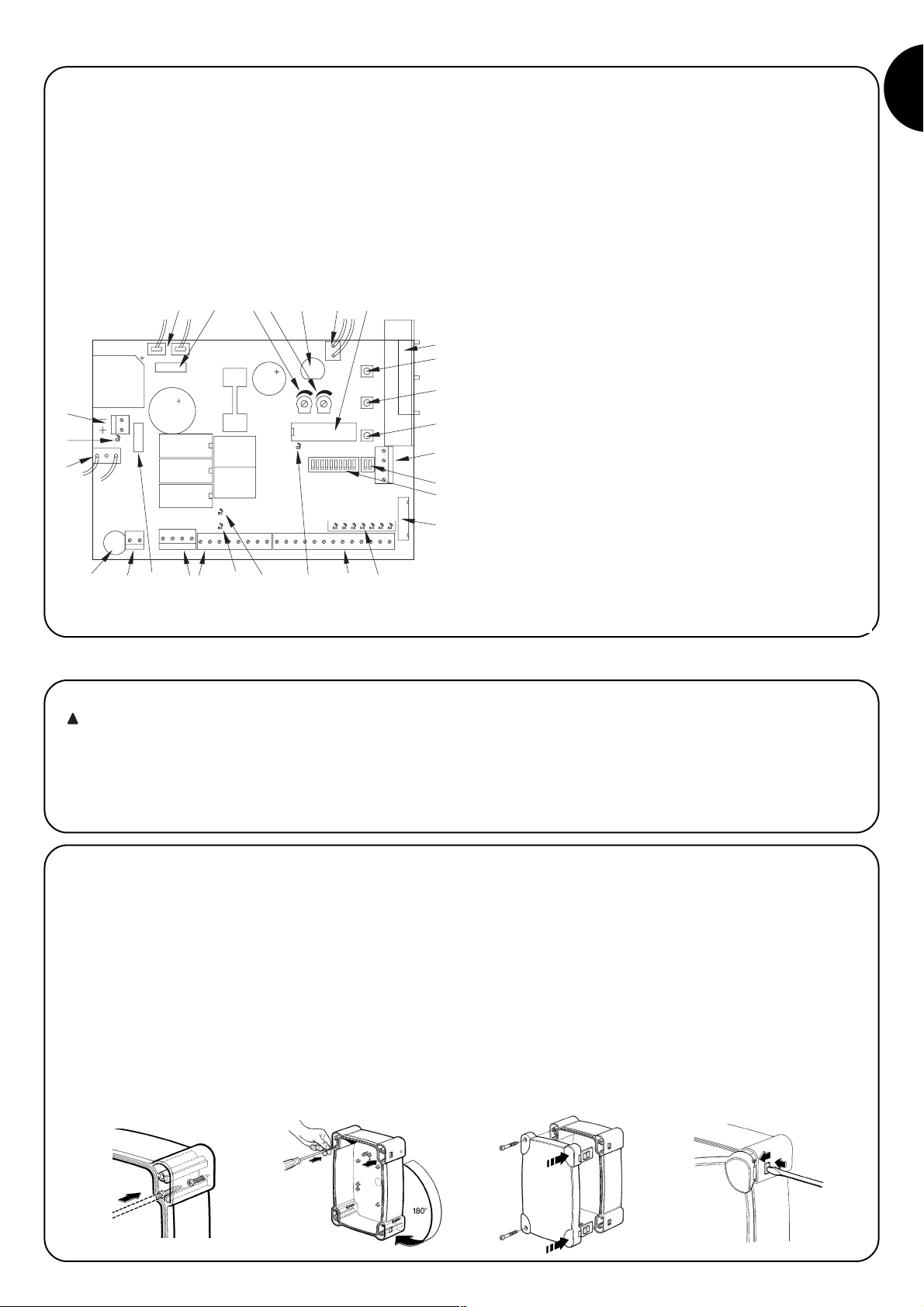
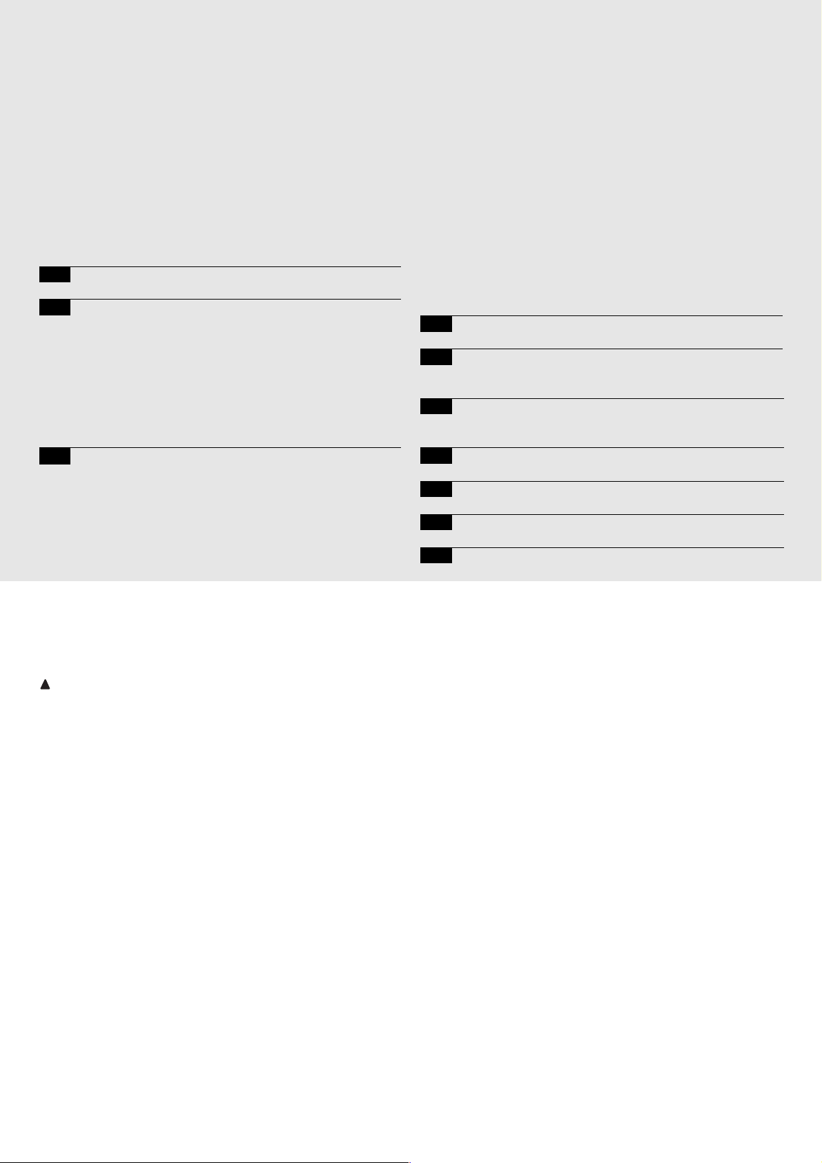
Fig. 1 offers an overall view of the board and indicates the main
components.
2.1) Preliminary checks
Automatic gate and door systems may only be installed
by qualified fitters in the full respect of the law.
Before starting installation:
• Comply with the warnings shown in the “Warnings for fitters” file.
• Make sure that the mechanical stops can stop the door from
moving and that they absorb all the kinetic energy accumulated
during movement without difficulty.
A Secondary transformer 1 connector
B Motor fuse (F2)
C Opening manoeuvre current adjustment
D Closing manoeuvre current adjustment
E Flashing light, electric block, photocell, service fuse (F3)
F Secondary transformer 2 connector
G Microprocessor
H Radio receiver slot
I “Open” button
J “Memory” button
K “Close” button
L Aerial terminal and second radio channel
M Dip Switch programming
N Dip Switch functions
O Connector for door controls
P Input led
Q Motor/input/output terminals
R “OK” led
S Release led
T Encoder led
U Battery fuse (F4)
V Power input terminals
W Line fuse (F1)
X Primary transformer connector
Y Battery led
Z Battery terminal
ABCD
2) Installation
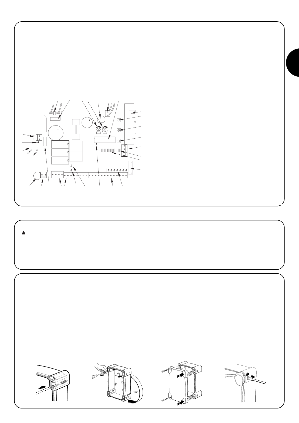
2.2) Mounting the A924 control unit
The unit is supplied in a container which, if appropriately installed,
will guarantee a protection level of IP55 which means it is also suitable for surface mounted installation.
How to mount the control unit:
• Install the unit on a permanent surface that is perfectly flat and
adequately protected against knocks, making sure the bottom
remains at least 40 cm from the ground.
• Install cable or pipe leads only at the bottom of the unit; for no
reason whatsoever must the side and top walls be perforated. The
cables must only enter the unit from the bottom!
• Fit the two screws into the relative upper holes by sliding them
along the guide (fig. 2A) and partially tighten them. Rotate the control unit 180° and do the same with the other two screws (fig. 2B).
Fix the control unit to the wall.
• Fit the cover as required (opening to the left or right) and press
hard where shown by the arrows (fig. 2C).
• To remove the cover, press on the hinge with a screwdriver and
push up (fig. 2D).
1) Description of the product
ABCDE FG
Z
Y
X
PQSRTQUVW
H
I
J
K
L
M
N
O
!
Page 6
6
BATTERY LED
FLASHING LIGHT 24Vcc
2
POWER INPUT
MAINS
1
ENCODER
MOTOR
LINE EARTH
MOTOR EARTH
Max 25W
5
3
4
8
9
7
6
M
19
COR
PHOTOTEST 24 Vcc
Max 200mA
Max 500 mA
ELECTRIC BLOCK 24Vcc
SERVICES 24 Vcc
SCA
COMMON 24Vcc
Max 200mA
14
12
11
13
10
18
161517
PHOTO 2
MAN
PARTIAL OPEN
OPEN
CLOSE
PHOTO
STOP
STEP BY STEP
24
23
20
21
22
27
26
25
F1
BATTERY
ENCODER LED
RELEASE LED
STEP BY STEP
CLOSE
PARTIAL OPEN
PHOTO2
PHOTO
STOP
OPEN
44
2ND RADIO CHANNEL
AERIAL
42
41
43
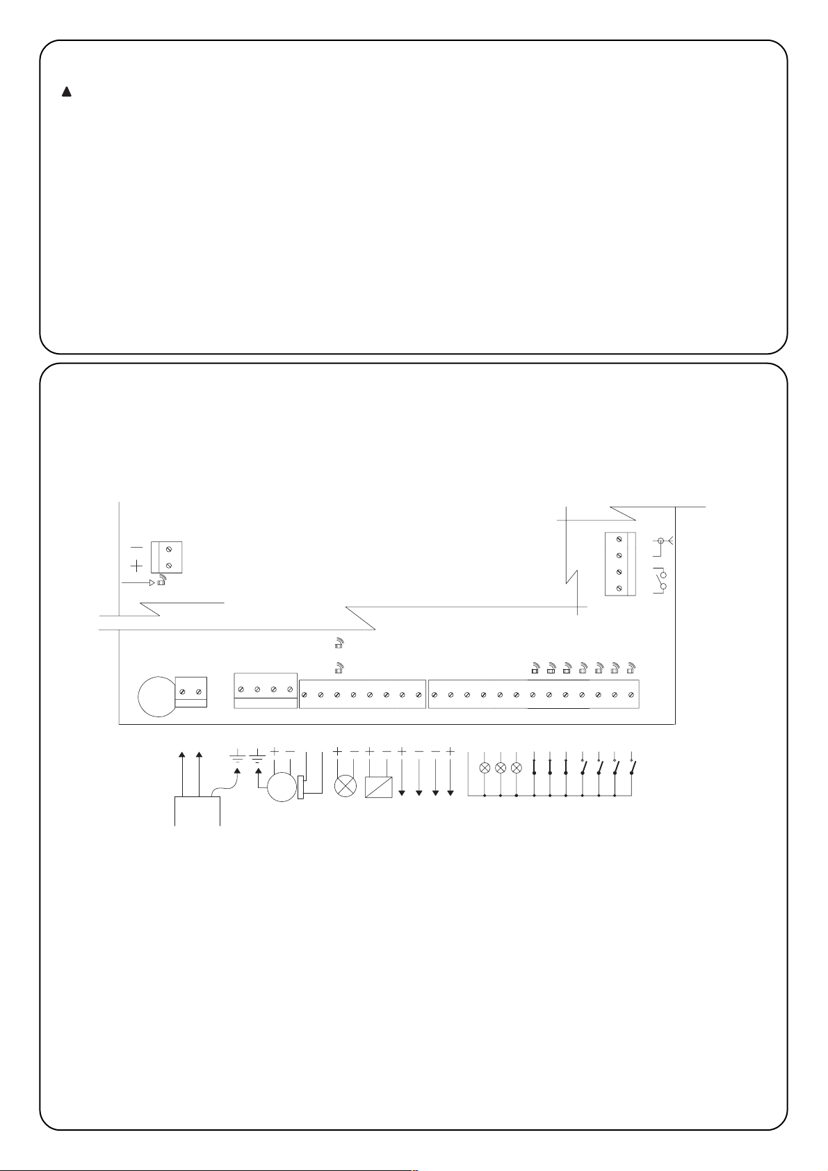
2.3) Electrical connections
To protect the operator and avoid damaging the components while electrical connections are being made or
the radio receiver is being connected, the control unit
may not be mains and/or battery powered
To make connections, please consult the electrical diagram (paragraph 2.4), bearing in mind that:
• The control unit must be powered with a 3 x 1.5mm
2
cable (phase,
neutral and earth); should the distance between the unit and the earth
connection exceed 30 m, an earth plate must be fitted near the unit
• For connections to SUMO, a 3x2.5 mm
2
cable must be used (if over
10m long, use 4mm
2
) for the motor and a 2 x 0.75mm2cable for the
encoder
• Use a cable with a minimum cross-section of 1 mm
2
to connect the
flashing light and the electrical block
• Wires with a minimum cross section of 0.25 mm
2
must be used to
connect very low voltage safety circuits; (use shielded wires if the
length exceeds 30 m and connect the earth braid at the control unit
end only)
• Maximum attention should be paid to polarised equipment (flashing
lamp, electric block, phototest output, services, battery, etc).
• If the inputs of the Normally Closed (NC) contacts are not used they
should be jumped with the “24Vdc Common” terminal; if the
Normally Open (NO) inputs are not used they should be left free.
• The contacts must be mechanical and potential-free; no stage
connections are allowed, such as those defined as "PNP", "NPN",
"Open Collector", etc.
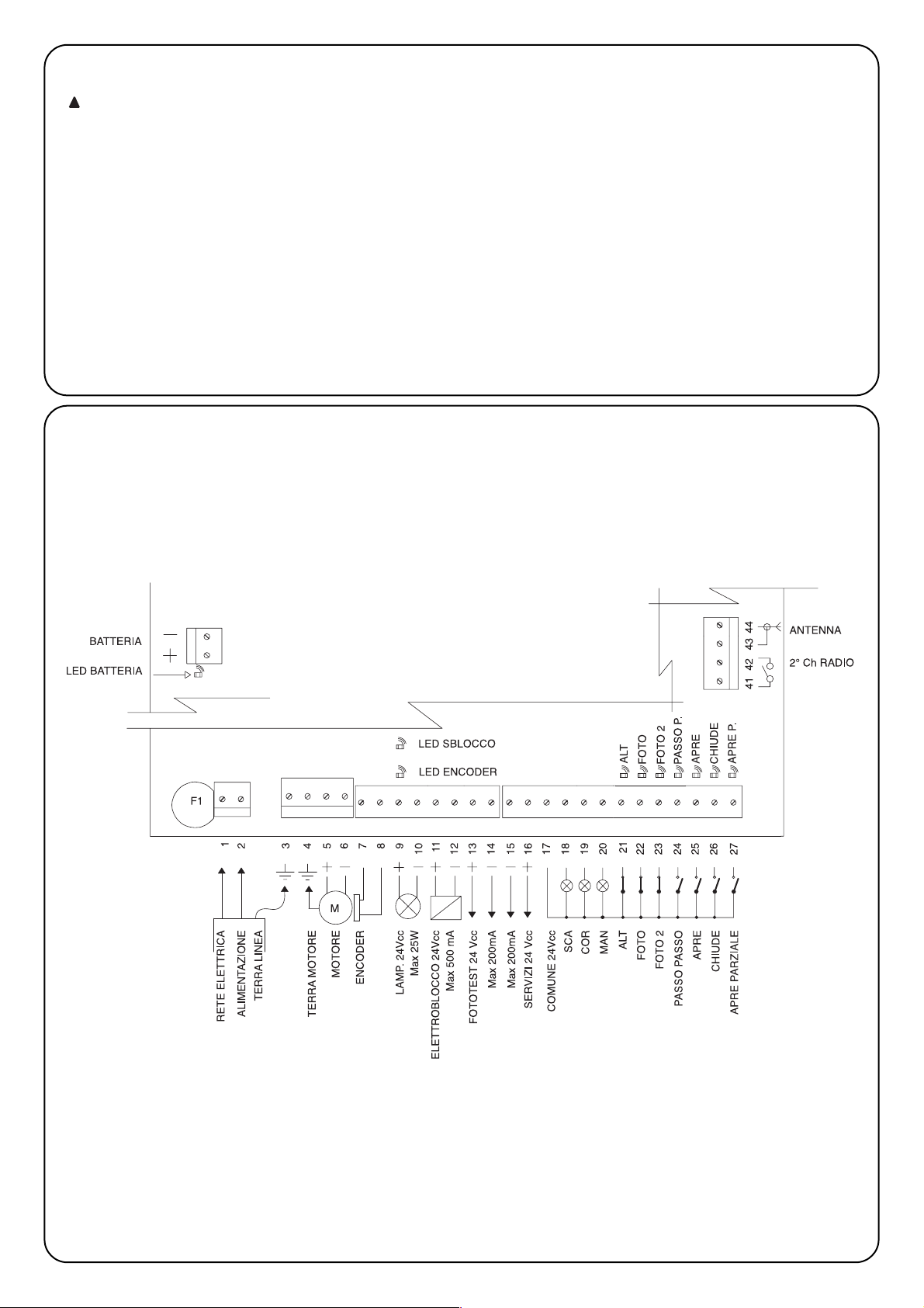
2.4) Electrical diagram
!
Page 7

GB
7
2.5) Description of connections
Terminals Functions Description
1-2 Phase - Neutral Mains power input
3 Earth Control unit earth connection
4 Earth Motor earth connection
5-6 Motor 36Vdc motor power input
7-8 Encoder Motor encoder input
9-10 Flashing lamp 24Vdc flashing lamp input max. 25W
11-12
Electrical block/Suction pad
24Vdc electrical block/suction pad output max. 500mA
13-14 Phototest Phototest output
15-16 24Vdc 24Vdc services power input max. 200mA
17 Common Common for all inputs
18 Sca Door open lamp output (on when the door is open, off when it is closed, flashes
slowly during the opening manoeuvre, flashes quickly during the closing manoeuvre)
19 Cor Courtesy lamp output (switches on when the manoeuvre begins and switches off 60
seconds after the manoeuvre has finished)
20 Man Maintenance lamp output
21 Stop Input with STOP function (Emergency, shutdown or extreme safety)
22 Photocell Input for safety devices (photoelectric cells, pneumatic edges) affecting the closing
manoeuvre
23 Photo 2 Input for safety devices (photoelectric cells, pneumatic edges) affecting the opening
manoeuvre
24 Step-by-step Input with cyclical Open-Stop-Close-Stop operation
25 Open Input for opening movement with cyclical Open-Stop-Open-Stop operation
26 Close Input for closing movement with cyclical Close-Stop-Close-Stop operation
27 Partial open Input with cyclical Partial Open - Stop - Close- Stop operation
41-42 2° Radio Ch Output for the second radio receiver channel
43-44 Aerial Input for the radio receiver aerial
+ - Battery 24 volt battery connection
Page 8
8
23
22
16
15
17
5423
RX
1
FOTO 2
TX
21
16
23
15
17
13
14
4231
RX
5
14
13
TX
21
FOTO 2
RX
54231
16
FOTO
TX
21
23
22
16
15
4231
RX
5
17
15
22
17
13
14
13
23
13
23
14
13
TX
21
FOTO
16
15
23
17
22
16
15
17
13
14
14
13
4231
RX
5
4231
RX
5
TX
21
TX
21
FOTO 2
FOTO
12 43251
5431221
17
22
23
16
15
RX
RXTX
TX
FOTO
FOTO 2
14
13
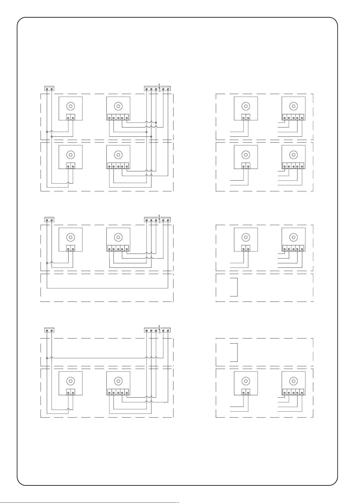
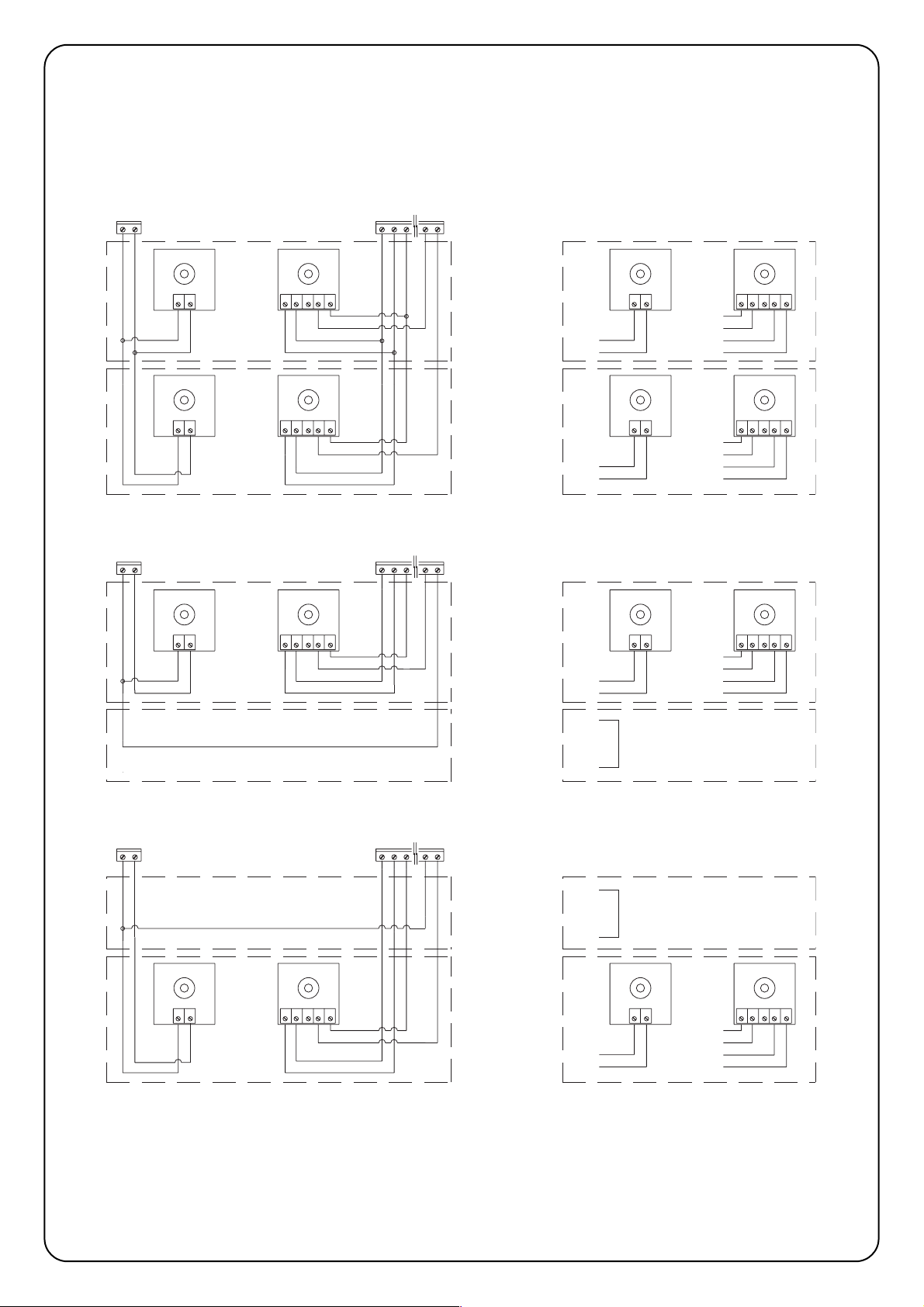
2.6) Phototest
The “Phototest” function is an excellent solution as regards the reliability of safety devices and puts the control unit and photocell
assembly into category 2 as per UNI EN 954-1 standard (ed.
12/1998).
In order to implement this solution, connect the photocells as shown
in one of the figures 3A, 3B or 3C, and move Dip-Switch 7 to On
(activate “Phototest”).
Fig. 3A Shows how to connect Phototest with the Photo and Photo2 photocells
Fig. 3B Shows how to connect Phototest with just the Photo photocell
Fig. 3C Shows how to connect Phototest with just the Photo 2 photocell
When movement is required, the unit first check that all the receivers
involved give their consent, then it turns off the phototest output
after which it checks that all the receivers signal the fact by removing their consent; the phototest output is finally reactivated and the
consent of all the receivers is verified once more. If a faulty device or
a shorted cable, etc., is detected during the above sequence, the
manoeuvre is not carried out.
PHOTO
PHOTO 2
PHOTO
PHOTO PHOTO
PHOTO 2
PHOTO 2 PHOTO 2
Page 9
GB
9
After making connections perform a general test, i.e.:
• Power the control unit and immediately check whether terminals 1-2 are mains powered and terminals 15-16 (services output) are
powered at approx. 28Vdc. If this is not the case, unplug the unit immediately and carefully check the connections and the voltage input.
• After about 2 seconds from switching on, the “OK” Led should show the control unit is working correctly by flashing regularly at 1 second
intervals.
• Check that the led’s relative to the NC inputs (“Stop”, “Photo” and “Photo2”) are on (safety devices active) and that the led’s relative to the
NO inputs are off (no command present); if this is not the case, check the connections of the various devices and make sure they are in
good working order.
• Check that all the safety devices of the unit are in proper working order (emergency stop, photocells, pneumatic edges, etc.); each time
they cut in, the relative “Stop”, “Photo” or “Photo2” led’s should turn off.
• Check the motor turns in the right direction, i.e.:
♦ release the motor and check that the release led on the board is on
♦ move the door manually so that it is free to move during the opening and closing manoeuvres;
♦ block the motor again and check that the release led is off
♦ press the “Close” button (ref. K of Fig. 1) and check that the door moves in the close direction
♦ if the opening manoeuvre is performed, press again on the close button to stop the door from moving, unplug the machine and invert
the two motor wires
♦ regardless of the direction of movement, press the “Close” button again to stop the manoeuvre immediately
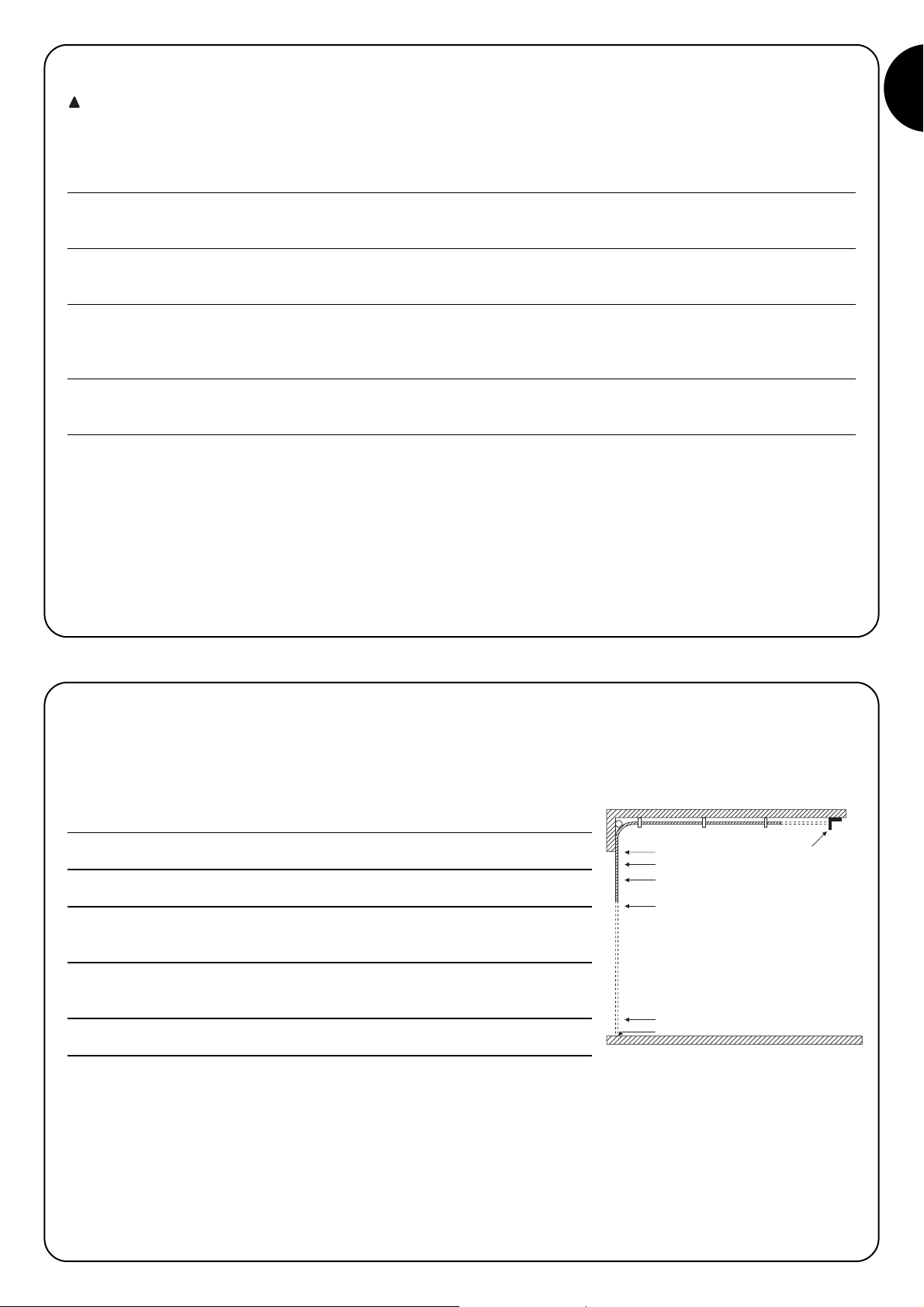
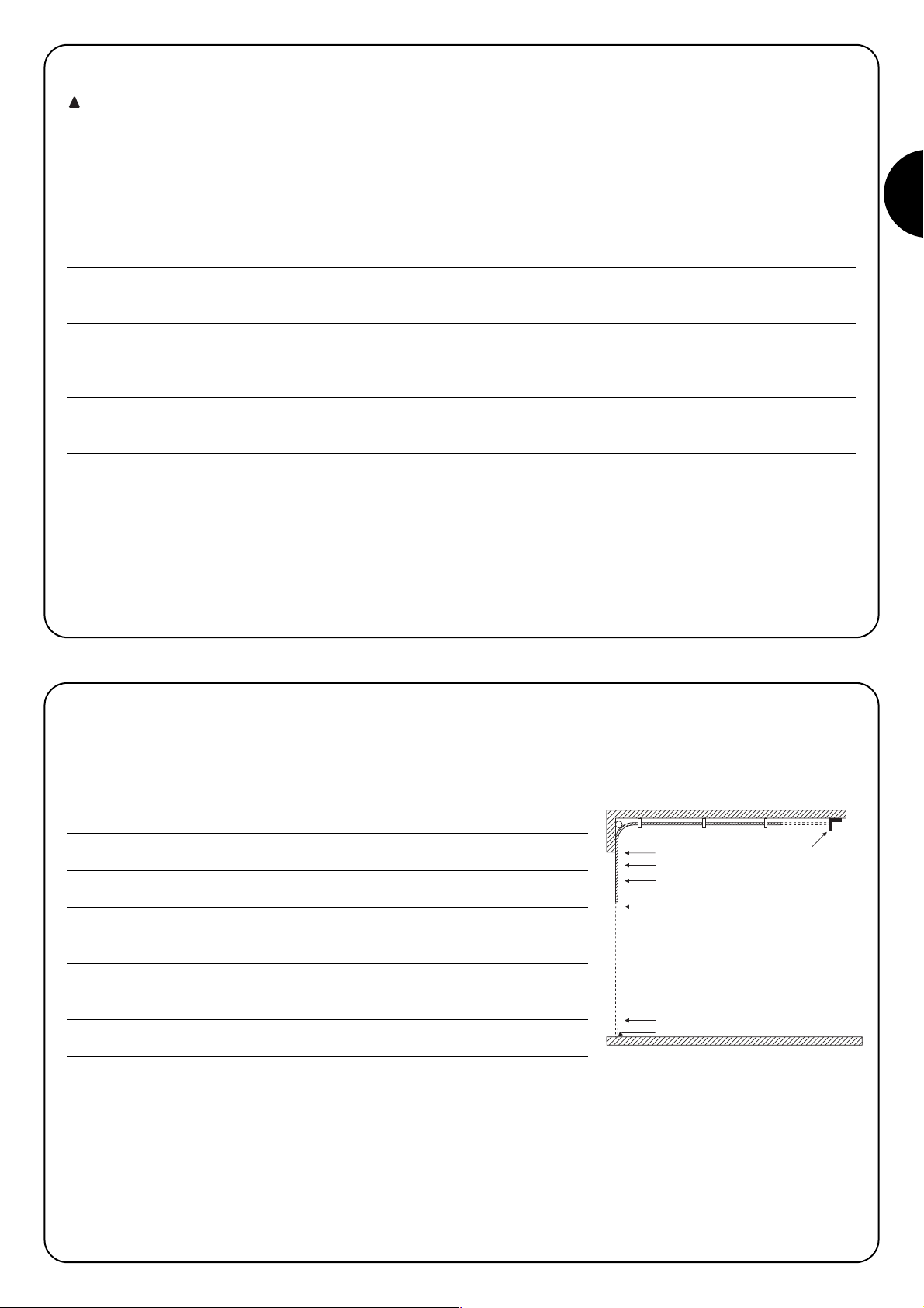
Once the connections have been successfully tested, the search for mechanical stops phase can begin.
This operation is important because the A924 control unit must measure the space covered by the motor, in terms of the number of encoder
impulses, to move the door from the maximum close position (position 0) to the maximum open position (position 1).
Position 0 and position 1 act as reference points for all the other positions indicated on the graph in Fig 4.
POSITION 0: is the point at which the sectional door is in the closed position, corresponding
to the mechanical stop (generally the floor).
POSITION 1: is the point at which the sectional door is in the maximum open position,
corresponding to the mechanical opening stops (point M).
POSITION A: is the point at which the door is required to stop during the opening manoeuvre
(this does not necessarily coincide with the mechanical stops in the opening cycle).
POSITION B: is the position in which the door is required to stop during the partial opening
manoeuvre.
POSITION RA: is the position in which the door is required to begin slowing down during the
normal opening manoeuvre.
POSITION RC: is the position in which the door is required to begin slowing down during the
closing manoeuvre.
The mechanical stops can be searched by means of an initial search, an automatic search or manual programming. After an “initial search”
or “automatic search”, one or more automatically detected positions can be modified by means of manual programming, if required, except
positions 0 and 1 which act as references for all the others.
3) Programming
2.7) Checking connections
The next operations involve work being done on live
circuits, some parts have mains voltage running through
them and are therefore extremely dangerous!
Pay the greatest of attention to what you are doing and
never work alone!
!
1
A
RA
B
RC
0
M
Page 10
10
3.1)
Initial search for mechanical stops
The "Initial search for mechanical stops” procedure is automatically performed as the first manoeuvre after installation.
Table “A” Activating the initial search for mechanical stops:
1. Release the motor and move the door manually so that it is free to move during the opening and closing manoeuvres; block
the motor.
2. Briefly press the “Open” button (ref. I, Fig. 1) or the “Close” button (ref. K, Fig. 1) on the board or give a command impulse
to the inputs and wait for the control unit to perform a slow closing manoeuvre to position 0, a slow opening manoeuvre to
position 1 and a rapid closing manoeuvre to position 0.
N.B. If the first manoeuvre after the command is an opening manoeuvre, give another command to stop the procedure and
invert motor polarity.
3. When the above procedure has finished, a mathematical operation is carried out to calculate position A (required opening)
at a few centimetres from the maximum open position, position B (partial opening) at about 3/4 from position A, and the RA
and RC positions required for slowing down.
4. The "Initial search" for the mechanical stops has terminated and the gear motor is now ready for use.
N.B. 1. If one of the safety devices cuts in or another command impulse is given during the "Initial search for mechanical stops", the door
will immediately stop moving and the above operations will have to be repeated from the beginning.
3.2) Automatic search for mechanical stops
As an alternative to the “Initial search” the “Automatic search for the mechanical stops” procedure can be performed at any time. This procedure automatically searches for the mechanical stops (position 0 and position 1) in precisely the same was described in the initial search section.
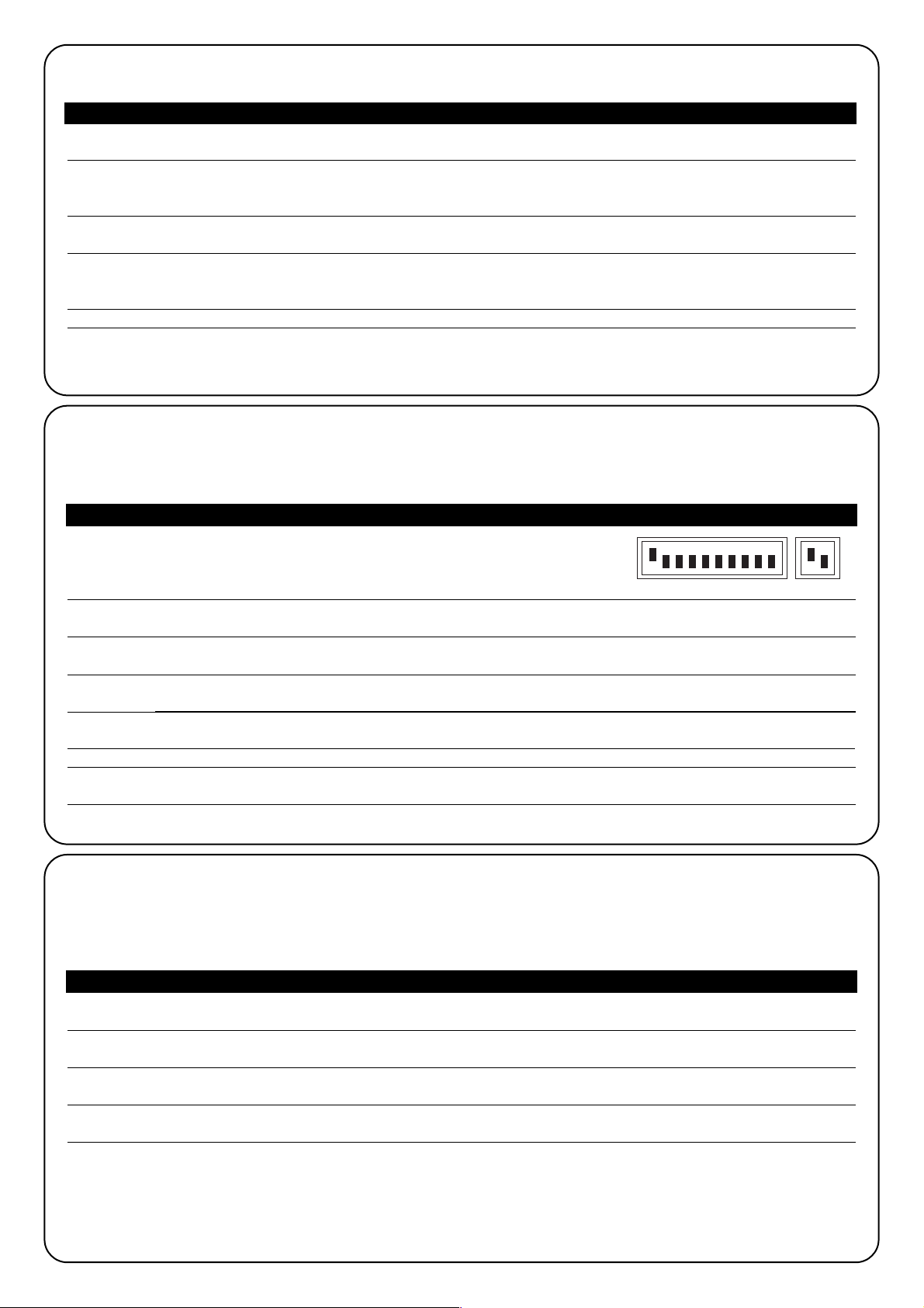
Table “B” Activating the automatic search for mechanical stops:
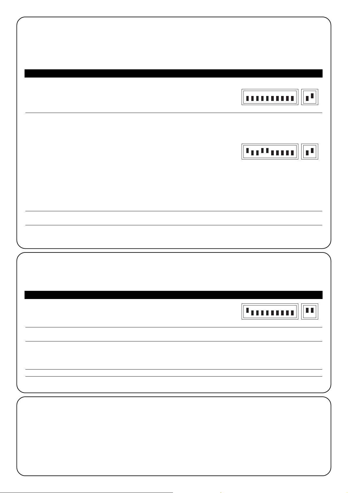
1. Set the Dip Switches as follows:
2. Release the motor and move the door manually so that it is free to move during the opening and closing manoeuvres; block
the motor.
3. Press the “Close” button (ref. K, Fig. 1) and wait for the control unit to perform a slow closing manoeuvre to position 0, a
slow opening manoeuvre to position 1 and a rapid closing manoeuvre to position 0.
N.B. If the first manoeuvre after the command is an opening manoeuvre, give another command to stop the procedure and
invert motor polarity.
4. Using the value of this position, a mathematical operation is carried out to calculate position A (required opening) at a few
centimetres from the maximum open position, position B (partial opening) at about 3/4 from position A, and the RA and RC
positions required for slowing down.
5. The "Automatic Search" for the mechanical stops has terminated and the gear motor is now ready for use.
N.B. 1. If one of the safety devices cuts in or another command impulse is given during the "Automatic search for mechanical stops", the
door will immediately stop moving and the above operations will have to be repeated from the beginning.
3.3) Memorisation procedure
At the end of the programming sequences of some parameters described in the next few paragraphs, the phase "Memorisation procedure" will be seen several times. This operation is used to transfer the value of the parameter required to be programmed into the perma-
nent memory of the control unit.
Table “C” Performing the memorisation procedure:
1. Press the “Memory” button (ref. J fig. 1) for at least 3 s, after 3 s the OK (ref. R, fig.1) led will flash quickly
2. Release the “Memory” button, the “OK” led will continue to flash quickly for another 3 s.
3. Within 3 s quickly press the “Open” and “Close” buttons (refs. I and K, fig. 1) together; when these two buttons are pressed
together, the ok led will switch off.
4. Release the two open and close buttons; the “Ok” led will light up for approx. 2 s as confirmation that the memorisation pro-
cedure of the selected parameter has terminated correctly
Table “B” Activating the search for mechanical stops:automatic
12345678910 11 12
Page 11
GB
11
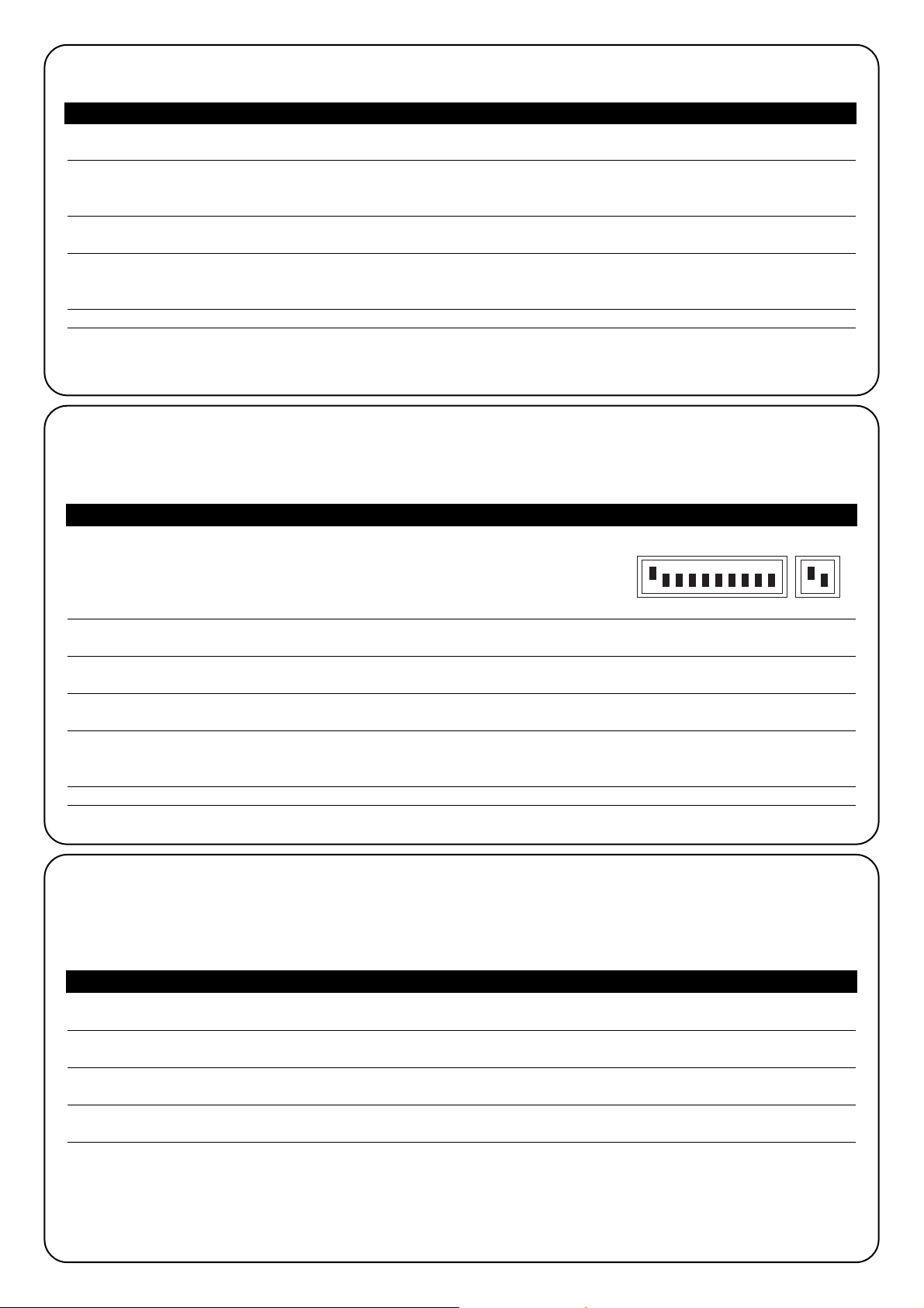
3.4) Manual programming of mechanical stops
This procedure involves manually entering all the positions indicated in Fig 4, respecting the order indicated in the following table; in partic-
ular, position 0 is the reference position and must be programmed first and never moved.
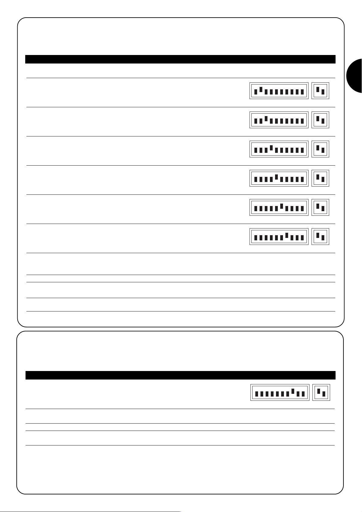
Table “D” Programming positions manually:
1. Set the dip switches to one of the following layouts depending on the parameter to memorise
POSITION 0: Mechanical stop in closing cycle
POSITION RC: Position at which the closing manoeuvre begins slowing down
POSITION B: Stopping position in the Partial opening manoeuvre
POSITION RA: Position at which the normal opening manoeuvre begins slowing
down
POSITION A: Stopping position in the Normal opening manoeuvre
POSITION 1: Mechanical stop in opening cycle
2. Press the “Open” button (ref. I, Fig. 1) or “Close” button (ref. K, Fig. 1) on the board and hold it down until the required position
is reached.
N.B. Press the “Memory” button (ref. J, Fig. 1) if acceleration is required.
3. When the position has been reached, release the buttons and perform the “Memorisation procedure” (paragraph 3.3)
N.B. 1. As an alternative to the manual programming of all the positions, just positions 0, A and 1 may be memorised while positions B, RA
and RC can be automatically calculated by the control unit.
3.5) Programming the electric block position
When the ELB output is assigned an electric block type of function (see switch 8 in paragraph 5) the threshold over which the output switches off can be programmed.
Table “E” Programming electric block positions:
1. Set the dip switches as shown in the figure:
2. Press the “Open” button (ref. I, Fig. 1) or the “Close” button (ref. K, Fig. 1) until the required position is reached
N.B. Press the “Memory” button (ref. J, Fig. 1) if acceleration is required.
3.
When the required position has been reached, release the buttons and perform the “Memorisation procedure” (paragraph 3.3)
12345678910 11 12
12345678910 11 12
12345678910 11 12
12345678910 11 12
12345678910 11 12
12345678910 11 12
12345678910 11 12
Page 12
12
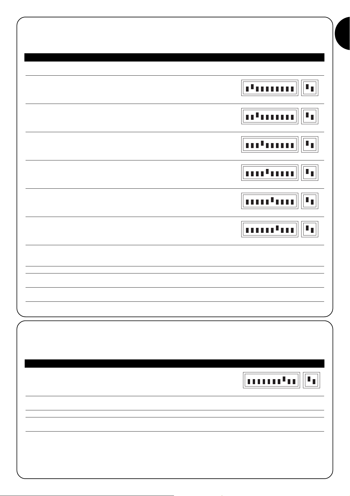
3.6) Programming the pause time
When the automatic close function is selected, a timer is activated after an opening cycle which controls the Pause Time; after this has
elapsed, a close manoeuvre is automatically activated. If this time has never been programmed, it is fixed by the control unit at 30 s, but the
following procedure allows any value between 1 and 1023 s (approx. 17 minutes) to be programmed.
Table“F” Programming the Pause Time:
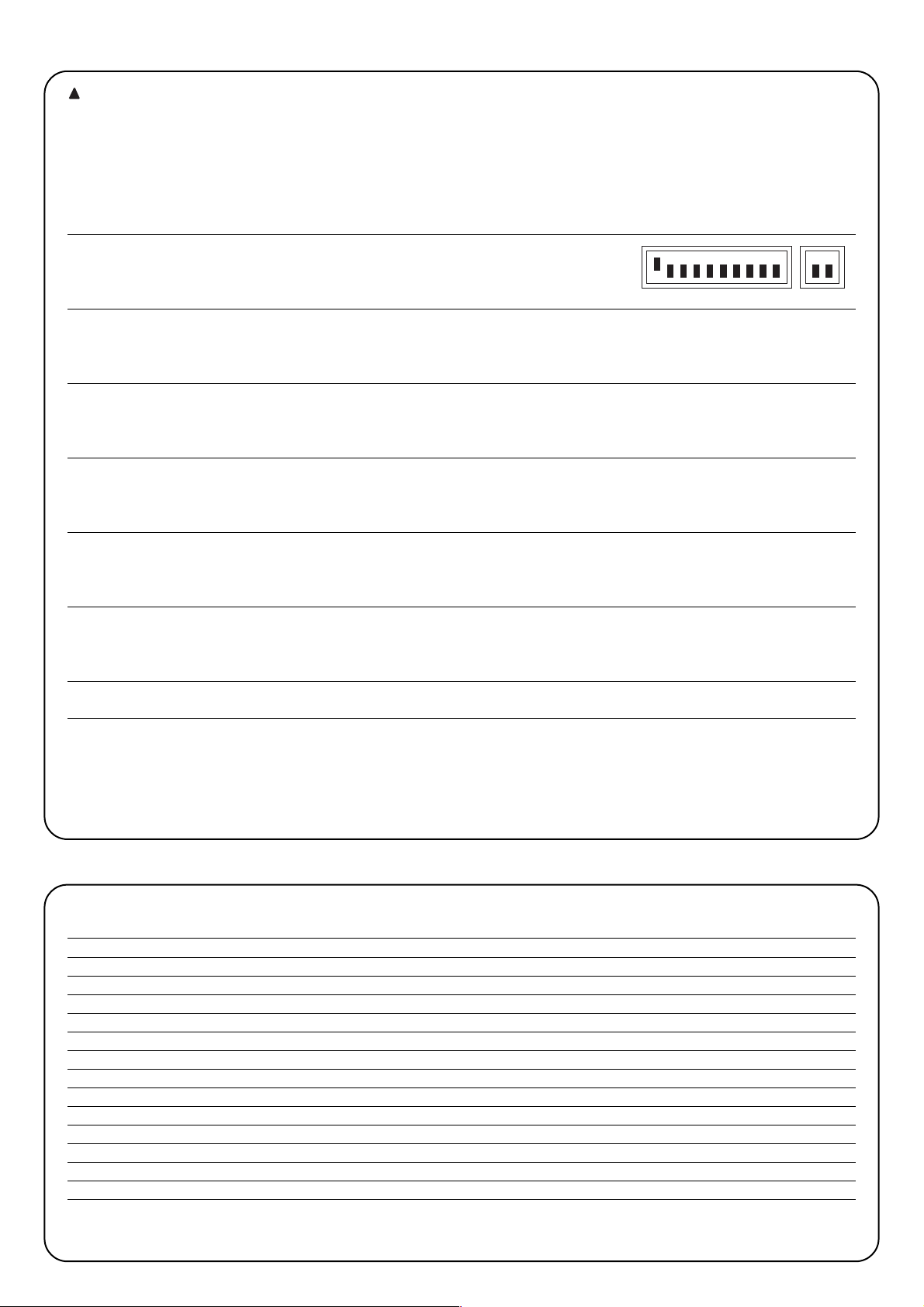
1. Set the dip switches as shown:
2. Select the required time with the 10-way dip switch bearing in mind that: Example: pause time 25 s
Dip 1 On activates a pause of 1 s 25 = 16+8+1
Dip 2 On " 2 " move dip switches 5 , 4 and 1 to On
Dip 3 On " 4 "
Dip 4 On " 8 "
Dip 5 On " 16 "
Dip 6 On " 32 "
Dip 7 On " 64 "
Dip 8 On " 128 "
Dip 9 On " 256 "
Dip 10 On " 512 "
If more than one Dip Switch is moved to On, the selected pause time is equal to the sum of the pause times of the single dip switches;
3. Perform the “Memorisation procedure” (paragraph 3.3)
3.7) Deleting the memory
All the programmable parameters are recorded in a permanent memory which stores the information even during a power failure; it may be
necessary to delete all the memorised data.
Table “G” Deleting the contents of the memory:
1. Set the Dip Switches as shown:
2. Perform the “memorisation procedure” (see paragraph 3.3) which in this case is used to confirm deletion.
N.B. When the memory is deleted it is as if the gear motor had never been installed and the door will therefore be unable to move normal-
ly; in this case the first command to reach the inputs or pressing the “Open” or “Close” buttons will immediately activate an "Initial Search
for mechanical stops" procedure.
N.B. 1. This operation does not cancel the number of manoeuvres performed or the number of scheduled manoeuvres.
3.8) Adjustments
Following the programming phase the few adjustments that are vital
for safe and correct operation of the automatic system must be
made
12345678910 11 12
12345678910 11 12
12345678910 11 12
Page 13
GB
13
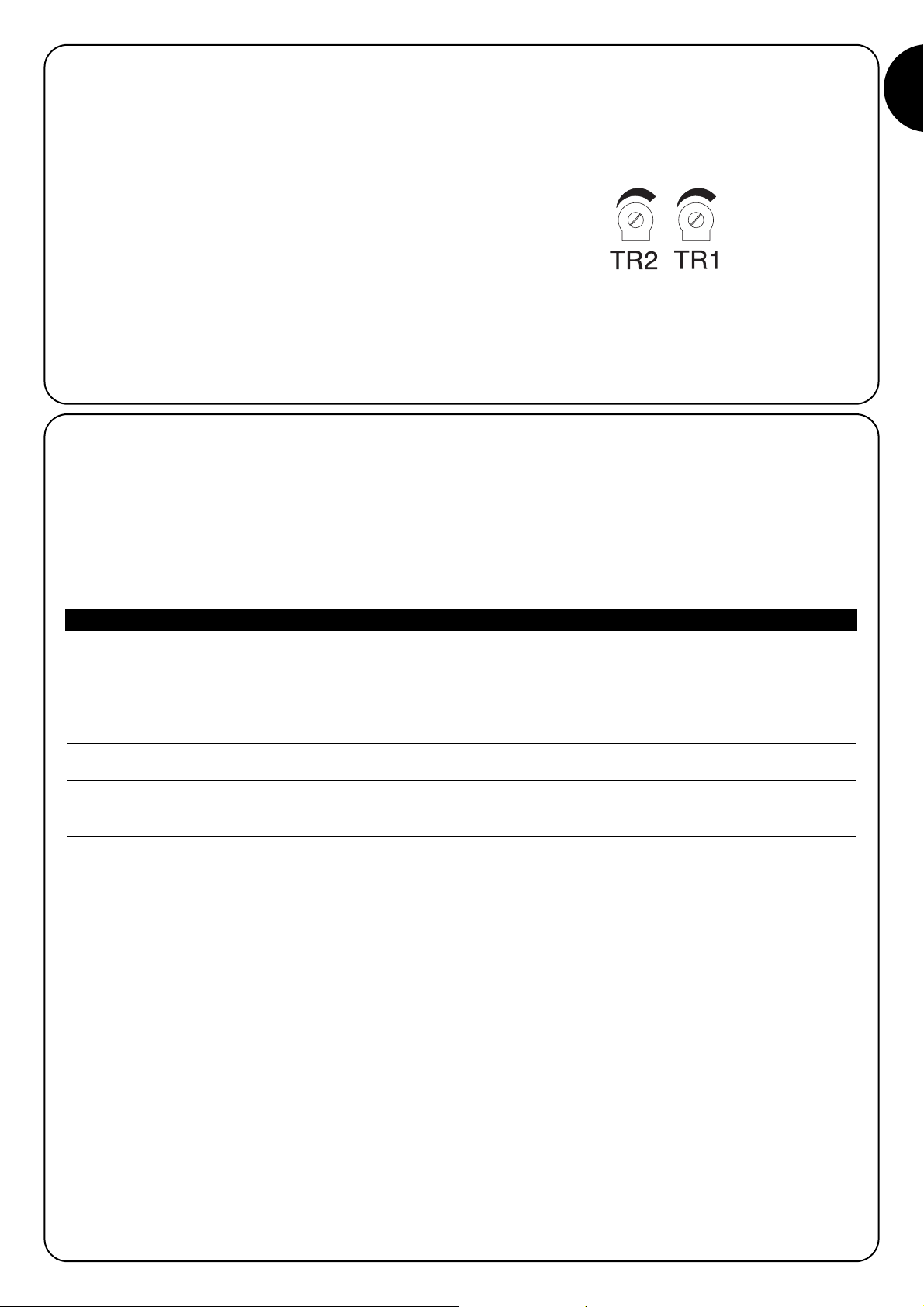
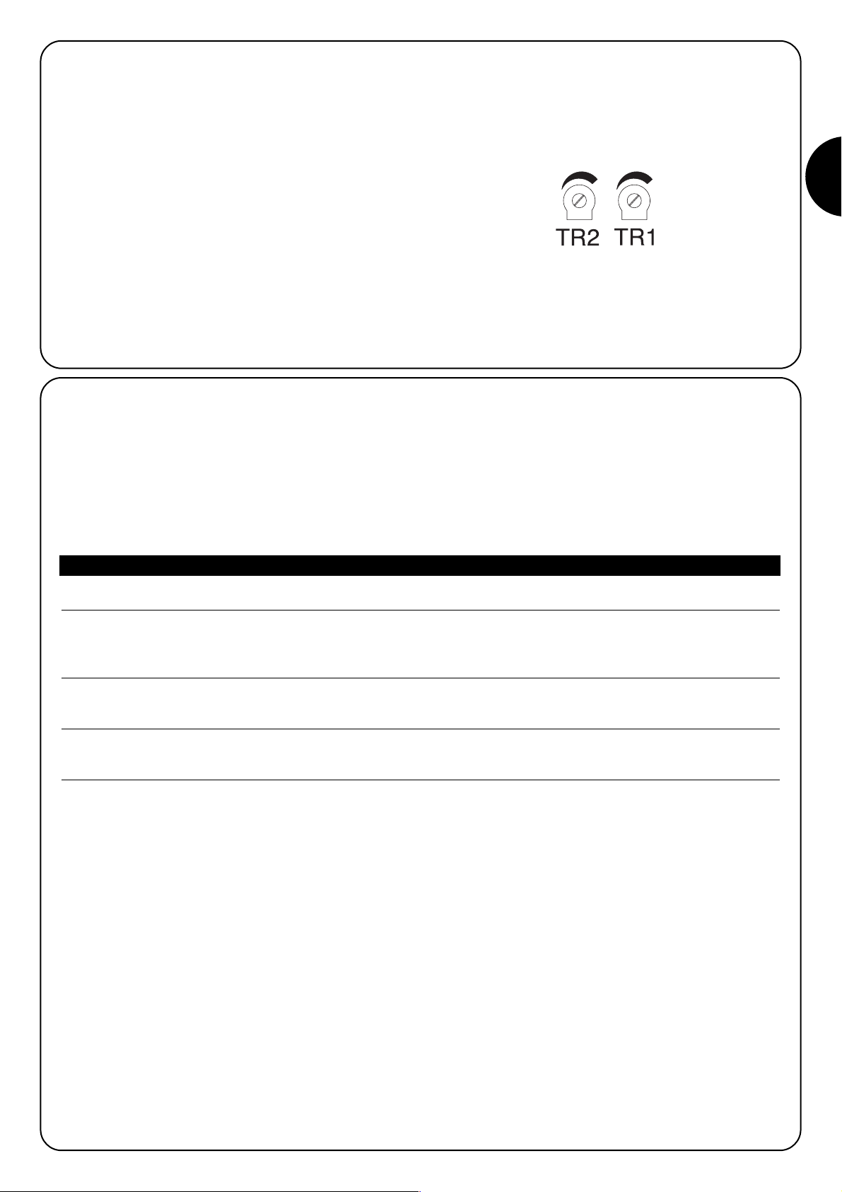
3.8.1) Current sensitivity adjustment
To limit the forces brought into play by the movement, a requirement
required by the regulations, the control unit features two trimmers TR2
(ref. C, Fig. 1) and TR1 (ref. D, Fig. 1) which allow the cut-in threshold
of the current sensitivity device to be varied during the opening
manoeuvre and closing manoeuvre respectively. If an obstacle is detected while the door is moving, it stops and, if the “Semiautomatic” or
“Automatic” operating mode is active, a manoeuvre in the opposite
direction is performed.
If the current sensitivity device cuts in during the closing manoeuvre, the
control unit reverses the direction of movement and the opening
manoeuvre, unless interrupted, terminates with the door against the
mechanical opening stop – position 1 (position reconfirmation)
In order to further increase the safety level, if the current sensitivity
device cuts in three times consecutively and prevents the door from
closing properly, movement is stopped preceded by a brief inversion.
TR2 = Opening manoeuvre current sensitivity adjustment.
TR1 = Closing manoeuvre current sensitivity adjustment.
3.8.2)
Speed adjustment
In order to reduce the kinetic energy released following an impact with an obstacle, as well as adjusting the cut-in threshold of the current
sensitivity device the speed of the door during normal operation can also be reduced.
Speed can be adjusted:
•
in the “Man present” mode only with the motor stopped,
•
in the “Semiautomatic” or “Automatic” mode either with motor stopped or while the door is moving (except for the acceleration and deceleration
phases).
Table “H”
Adjusting speed:
1.
Press and hold down the “Memory” button (Ref. J, Fig. 1)
2.
After a second…
♦
press and hold down the “Close” button (ref. K, Fig. 1) to decrease speed, or
♦
press and hold down the “Open” button (ref. I, Fig 1) to increase speed
3.
As soon as the speed has reached the required value, release the buttons (the new speed is automatically memorised)
N.B. The adjustment system is effective until the min. or max. limit values corresponding to the speeds indicated in the motor instructions book
are reached; when these limits are reached the “OK” led lights up and remains on when the maximum value has been reached and off when the
minimum value has been reached.
Page 14
14
The automation system must be tested by qualified and expert staff who must establish what tests to perform according
to the relative risk.
Testing is the most important part of the whole installation phase. Each single component, e.g. the motor, emergency stop, photocells, etc., may
require a specific test phase; please follow the procedures shown in the respective instructions manuals.
To test the A924 control unit, perform the following operations:
1.
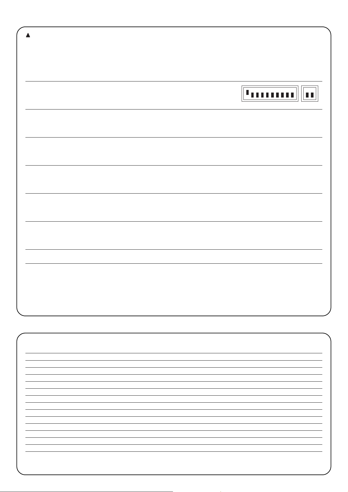
Set the Dip Switches as shown:
(all the functions deactivated and semiautomatic operation)
2.
Press the “Open” button (ref. I, fig. 1) and check that:
•
the flashing lamp activates
•
an opening manoeuvre starts with the acceleration phase
•
the door stops moving, preceded by a deceleration phase, when it reaches position A.
3.
Press the “Close” button (ref. K, fig. 1) and check that:
•
the flashing lamp activates
•
a closing manoeuvre starts
•
the door stops moving when it reaches position 0.
4.
Perform an opening manoeuvre and check that the cut-in of a device connected to the:
• “
Stop” input immediately stops the door moving
• “
Photo” input has no effect
• “
Photo2” input stops and inverts the manoeuvre
5.
Perform a closing manoeuvre and check that the cut-in of a device connected to the:
• “
Stop” input immediately stops the door moving
• “
Photo” input stops and inverts the manoeuvre
•
“Photo2” input has no effect
6.
Engage a device connected to the:
• “
Stop” input and check that no manoeuvre is performed when a command input is activated
• “
Photo” input and check that no manoeuvre is performed when a command input causing a closing manoeuvre is activated
• “
Photo2” input and check that no manoeuvre is performed when a command input causing an opening manoeuvre is activated
7.
During both the opening and the closing manoeuvres, stop the door from moving by introducing an obstacle and check that the
manoeuvre inverts before the force indicated by law is exceeded.
8.
Check that the activation of the inputs (of connected) causes a step in the sequence
•
for the “Step-by-Step” input: Open – Stop – Close –Stop,
•
for the “Open” input: Open – Stop – Open –Stop,
•
for the “Close” input: Close – Stop – Close –Stop,
•
for the “Partial Open” input: Partial Open – Stop – Close –Stop,
5)
Selectable functions
When dip switch programming is Off, the dip switch function allows various other functions to be selected, as shown below:
Switch 1-2 Off Off =
“Manual” function, i.e.: Man Present
On Off =
“Semiautomatic” function
Off On =
“Automatic” function, i.e.: Automatic Closing
On On =
“Automatic + Always Closes” function
Switch 3 On =
Condominium function <Not available in the Manual mode>
Switch 4 On =
5 s pre-flashing (2 s in the manual mode)
Switch 5 On =
Close again 5 s after Photo in the automatic mode or close again after Photo in the semiautomatic mode
Switch 6 On =
“Photo” also in the opening manoeuvre
Switch 7 On =
Activate Phototest
Switch 8 On =
Suction pad/Electrical block (On = suction pad Off = electrical block)
Switch 9 On =
Traffic light in the “one way” mode
Switch 10 On =
Traffic light in the “two way” mode
N.B. Naturally, if a Switch is "Off" its associated function is not activated.
4)
Testing
!
12345678910 11 12
Page 15
GB
15
5.1)
Description of functions
Man present Function
A movement is only made after a command is given. The Movement stops as soon as the command terminates or after a safety device triggers
(“Stop”, “Photo” or “Photo2”) or the current sensitivity device cuts in. As soon as the movement stops, the command must be stopped before
another movement can begin.
Semiautomatic and automatic function
In the "Semiautomatic" or “Automatic” functions, following a command impulse the whole movement is performed until the required position is reached.
A second impulse on the input that began the movement will cause it to stop. If, instead of a impulse to a command input a continuous signal is maintained, a state of priority will be created in which the other command inputs are disabled (useful when connecting an opening timer, for example).
If the current sensitivity device or a photocell involved in the direction of movement (“Photo” when closing, “Photo2” when opening) cuts in during a
manoeuvre, the direction of movement will be inverted.
In the “Automatic” operating mode, an opening manoeuvre is followed by a pause and then a closing manoeuvre.
If “Photo” triggers during the pause, the timer will be reset with a new pause time; if, on the other hand, the Stop input triggers during the pause, the
closing function will be cancelled and the system will Stop.
Always close function
Automatically starts a closing manoeuvre, preceded by 5 s of pre-flashing, if a door is found to be open when power is resumed.
Condominium function
In the “Condominium” function, an opening manoeuvre cannot be interrupted by command impulses except for those triggering a closing manoeuvre. During a closing manoeuvre, a new command pulse will stop the gate and reverse the direction of movement in order to open the gate.
Pre-flashing
Following a command impulse, the flashing lamp is triggered first and then, 5 seconds later (2 seconds later in the manual mode) the manoeuvre begins.
Close again 5 s after Photo in the automatic mode or close again after Photo in the semiautomatic mode
If Photo triggers in the automatic mode during an opening or closing manoeuvre the pause time is reduced to 5 s regardless of the programmed pause time.
If Photo triggers in the semiautomatic mode during a closing manoeuvre the automatic closing manoeuvre is activated with the programmed pause time.
Photo also in the opening manoeuvre
With this function, if the “Photo” safety device triggers, movement will also be interrupted in the opening manoeuvre; if the “Semiautomatic” or
“Automatic” functions are selected, the opening movement will continue as soon as “Photo” disengages.
Activate Phototest
This function tests the photoelectric cells before each manoeuvre begins, thereby increasing system safety.
For further details, please consult paragraph 2.6 Phototest
Suction pad/electrical block
This function assigns the following functions to the Elb output (terminals 11 and 12):
•
electrical block (Switch 8 Off) - the output activates during the opening manoeuvre starting from the closed door and remains active until the
door exceeds the electrical block position (programmable, see paragraph 3.5);
•
suction pad (Switch 8 On) – the output activates at the end of the closing manoeuvre and remains active for the whole time the door is closed.
Traffic light in the one way mode
In this mode, the SCA output is active when the door is open and remains on during the opening manoeuvre while it switches off during the closing manoeuvre and when the door is closed. In this way, a green light can be fitted to the output that, when on, indicates the road is clear.
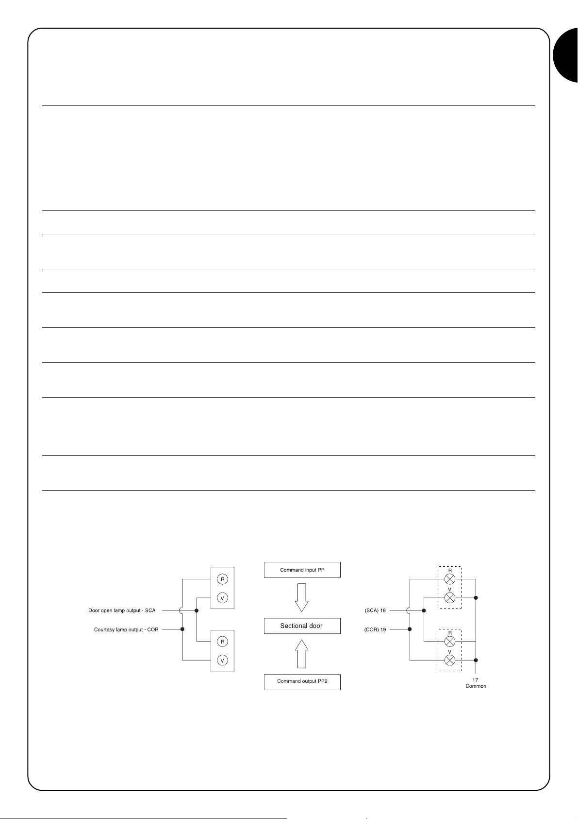
Traffic light in the two way mode
When switch 10 is On, regardless of the position of switch 9, the “traffic light in the two way” mode is activated; the following changes take place
in the control unit: the “Open” input becomes “Step-by-Step2”, while the two “Courtesy light” (COR) and “Door open led” (SCA) outputs become
Green Light in one direction and Green Light in the other, as shown in Fig. 5. A different opening command is given for each direction of movement: “Step-by-Step” (PP) for entering and “Step-by-Step2” (PP2) for exiting; two traffic lights are therefore installed with Red and Green signals
connected to the SCA and COR outputs.
The two SCA and COR outputs are normally off and, as a result, so are the traffic lights; when an open command is given with PP, the opening
manoeuvre begins while SCA activates at the same time to switch on the green entry light and the red exit light. If instead the open command is given by PP2, the COR output activates the green exit light and the red entry light. The light will remain on during the whole opening phase and the
pause phase, if any; during the closing phase, instead, the green and red lights are activated together to indicate there is no longer transit priority.
The two outputs can directly control small 24Vdc lamps for a maximum total of 10W per output. If more powerful lamps are required, it is best to
use relays piloted by the control unit outputs that in turn command the traffic lights.
Page 16

16
6)
Servicing
The control unit is an electronic component and therefore needs no particular maintenance; however, the board and the relative connected devices
should be periodically checked (at least every 6 months) by carrying out the whole testing procedure (see Chap. 4).
In order to plan the maintenance programme for the whole system, a manoeuvre counter has been fitted to the control unit which increases its value after every opening manoeuvre. The Maintenance (MAN) led flashes to signal this increase. The value of the manoeuvre counter is constantly
compared with an alarm threshold (programmable by the fitter) and the warning threshold (automatically set to the alarm threshold less about 6%).
When the number of manoeuvres performed exceeds the warning threshold, the maintenance led only flashes during manoeuvres, while if the alarm
threshold is exceeded it continues to flash (with the motor stopped and moving) in order to signal that maintenance must be performed.
The alarm threshold can be programmed from a minimum value of 200 to a maximum value of 50800 manoeuvres in multiples of 200.
Tabella “I”
Programming the alarm threshold
1.
Set the dip switches as shown
2.
Divide the number of manoeuvres to programme by 100 and then by 2 Example: number of manoeuvres
3.
Consult the table to find the combination of Dip Switches giving the same total value to programme: 30,000
as the above number and move the relative Dip Switches to On. Results after dividing: 150
150 = 128 + 16 + 4 + 2,
Dip Switches 5 , 8, 3 and 2 to On
4.
Perform the “Memorisation procedure” (see paragraph 3.3)
After programming the alarm threshold, visualise it in order to check the operation was performed correctly.
Table “L”
Visualising the alarm threshold
1.
Set the dip switches as shown:
2.
Move the Dip Switch 1 to On (2,3,4 and 5 to Off), count the number of times the ok led flashes and write the number on a piece
of paper (if it is 10, write 0)
3.
Repeat the operation with Dip Switches 2, 3, 4 and 5
4.
Reconstruct the number of manoeuvres as shown in one of the following two examples
Use the same procedure to visualise the number of manoeuvres performed;
Tabella “M”
To visualise the number of manoeuvres performed
1.
Set the dip switches as shown:
2.
Count the number of times the “OK” led flashes with Dip Switches 1, 2, 3, 4 and 5 as shown in examples 1 or 2.
N
.B. whenever the warning threshold is programmed the number of manoeuvres performed is automatically cancelled.
Dip-switch Sw1 Sw2 Sw3 Sw4 Sw5 Sw6 Sw7 Sw8
Value 1248163264128
Dip Switch
arrangement
Number of
manoeuvres
Example
n° 1
Number of times
“OK” led flashes
10
1
1
4
2
10
10
10
4
7
1.204
Example
n° 2
Number of times
“OK” led flashes
14.007
12345678910 11 12
12345678910 11 12
12345678910 11 12
123456 123456 123456
123456
123456
12345678910 11 12
Page 17
GB
17
6.1) Disposal
This product is made from various kinds of material, some of which can
be recycled. Make sure you recycle or dispose of the product in compliance with current laws and bye-laws.
Some electronic components may contain polluting
substances; do not dump them.
The control unit features a connector for plugging in a radio receiver
(optional accessory) which activates the Step-by-Step input and allows
the control unit to be remote-controlled with a transmitter. The clean
contact for the second channel is available on terminal 41-42.
Before fitting the receiver, disconnect mains power and any batteries
and plug in the receiver with its components directed towards the control unit microprocessor.
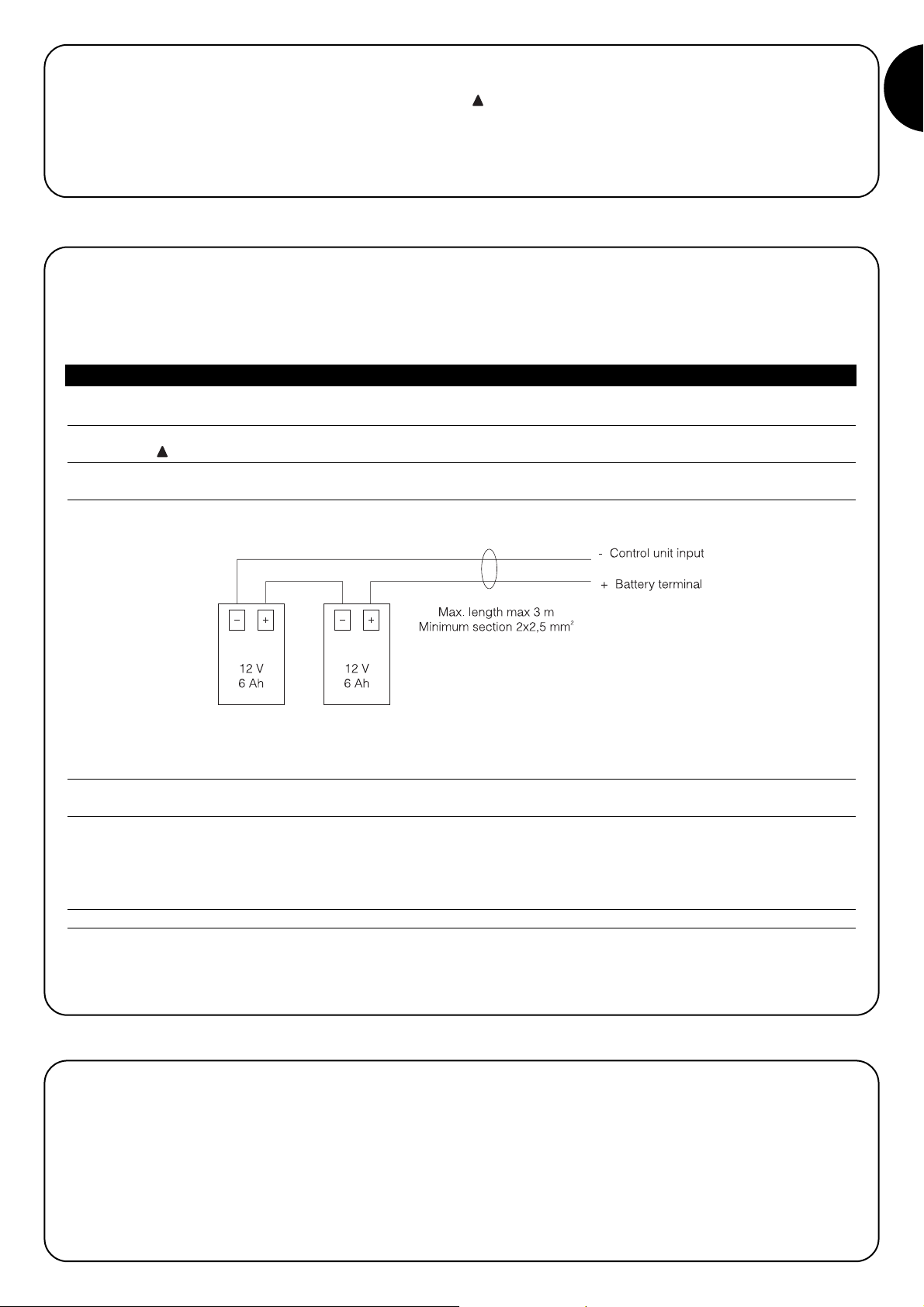
The control unit contains a large enough transformer to cater for the power requirements of the motor and the electronic board when directly powered by the mains supply. If the system is required to work even when mains power is unavailable, suitable batteries should be connected. When
mains power is used, the control unit charges these batteries, while when mains power is unavailable, the control unit automatically switches to
the battery mode.
Tabella “N”
Connecting the batteries
1.
Before connecting the batteries, install the system and make sure everything works correctly.
2.
Check that the battery led is on and that voltage at the terminals is approximately 27 volt.
Perform the next operation with great care as it involves working on live circuits.
3.
Connect the batteries as shown in Fig. 6.
4.
Immediately after connecting the batteries to the control unit, check that the battery led is still on; if it is off, disconnect the batteries
immediately and check the polarity of the connection.
5.
If the battery led is on, check the voltage on the battery terminals again; if voltage is:
•
lower than 18 Vdc, the batteries are not connected correctly or they are faulty
•
between 18 and 25 Vdc, the batteries are flat; wait for them to recharge
•
higher than 25 Vdc, the batteries are charged, disconnect mains power, check the system continues to work correctly and then
reconnect mains power.
N
.B. In the battery mode, the motor moves more slowly than when the control unit is powered by the mains.
N
.B. 1. If both power systems are present (mains power and batteries) and you want to disconnect the power unit for maintenance or safety
purposes, as well as disconnecting mains power, you must also disconnect the batteries or remove the F4 battery fuse on the control unit.
7) Battery operation
8) Radio receiver
!
!
Page 18

18
Some of the most common problems that can occur during installation are indicated below.
• No Led is on:
check terminals 1 and 2 for mains voltage and make sure fuses F1 or F3 have not blown.
• The manoeuvre does not start:
check that the safety input led’s “Stop”, “Photo” and “Photo2” are active and that the motor is blocked (release led off).
• The direction of movement is inverted during the manoeuvre:
check that no safety devices have triggered (“Photo” in the closing manoeuvre and “Photo2” in the opening manoeuvre) or that the current
sensitivity device has not cut in; in the latter case check that the adjustment is sufficient for the movement of the door. If this is not the
case, increase the level by rotating one of the two trimmers clockwise (TR2 for opening, TR1 for closing).
• The “OK” led flashes quickly:
the input voltage is insufficient or an incorrect combination has been selected with the Dip switches.
• The motor moves slowly:
if it was previously released, the control unit is performing an alignment operation; the first cut-in of the current sensitivity device is
considered as a mechanical stop and the correct position is recalled from the memory.
• The motor performs the acceleration phase and stops:
check whether the encoder led flashes while the motor is moving. The led may flash at different speeds depending on the speed of
movement. When the motor is stopped the led may be on or off depending on the position in which the motor shaft stopped.
• The “OK” led remains on for a few seconds immediately after a command:
this shows there is a fault in the motor command stage; check the wiring and earth connection of the motor, other wise replace the
control unit.
9) What to do if…
Power input : A924 control unit ➡ 230 Vac ± 10 %, 50-60Hz
: A924/V1 control unit ➡ 120 Vac ± 10 %, 50-60Hz
Power from batteries : 21 ÷ 28 Vdc (two 12 volt batteries, capacity 6Ah)
Current sensitivity adjustment : from 2.5 to 15 A
Service output : 24 Vdc, maximum current 200mA
Phototest output : 24 Vdc maximum current 200 mA
Flashing lamp output : 24 Vdc maximum power 25 W
Electrical block output : 24 Vdc maximum current 500 mA
SCA led output : 24 Vdc maximum power 5W
Courtesy light output : 24 Vdc maximum power 5W
Maintenance led output : 24 Vdc maximum power 2 W
Pause Time : programmable from 1 to 1023 seconds
Battery charger voltage: : 27 V
dc
Charge current : 200 mA
Complete charge time : approx. 24 h for two 12V - 6Ah batteries
Operating temperature : -20 a +70 °C
Protected to : IP55
Dimensions and weight : 220 x 280 h 110, approx. 4 Kg
10) Technical features
Page 19

19
Nice reserves the right to modify the products whenever it sees fit.
Page 20
20
mindy A924
Avvertenze:
Il presente manuale è destinato solamente al personale
tecnico qualificato per l'installazione. Nessuna informazione
contenuta nel presente fascicolo può essere considerata
d’interesse per l'utilizzatore finale! Questo manuale è riferito
alla centrale A924 e non deve essere utilizzato per prodotti
diversi. La centrale A924 è destinata al comando
dell’attuatore elettromeccanico SUMO prodotto dalla Nice
s.p.a; ogni altro uso è improprio e quindi vietato dalle
normative vigenti. Si consiglia di leggere attentamente tutte
la istruzioni prima di procedere con l’installazione.
Indice: pag.
1 Descrizione del prodotto 21
2 Installazione 21
2.1 Verifiche preliminari 21
2.2 Fissaggio centrale A924 21
2.3 Collegamenti elettrici 22
2.4 Schema elettrico 22
2.5 Descrizione dei collegamenti 23
2.6 Fototest 24
2.7 Verifica dei collegamenti 25
3 Programmazione 25
3.1 Ricerca iniziale degli arresti meccanici 26
3.2 Ricerca automatica degli arresti meccanici 26
3.3 Procedura di memorizzazione 26
3.4 Programmazione manuale degli arresti meccanici 27
3.5 Programmazione quota elettroblocco 27
3.6 Programmazione tempo pausa 28
3.7 Cancellazione della memoria 28
3.8 Regolazioni 28
3.8.1 Regolazione amperometrica 29
3.8.2 Regolazione velocita 29
4 Collaudo 30
5 Funzioni selezionabili 30
5.1 Descrizione delle funzioni 31
6 Manutenzione 32
6.1 Smaltimento 33
7 Funzionamento a batterie 33
8 Ricevitore radio 33
9 Cosa fare se… 34
10 Caratteristiche tecniche 34
!
Page 21
I
21
I
l principio di funzionamento della centrale A924 si basa su sistema
di controllo della posizione funzionante mediante un sensore
magnetico (encoder), inserito all’interno del motore. Questa tecnica
permette la rilevazione dei gradi di rotazione dell'albero e rende
possibili funzioni di posizionamento e regolazione della velocità non
realizzabili con controlli tradizionali. Grazie al controllo della velocità
e della coppia motore, la centrale è in grado di rilevare la presenza
di un ostacolo (“funzione amperometrica”).
La centrale ha un contatore di manovre che permette la gestione degli
interventi di manutenzione, è predisposta per l'inserimento dei
ricevitori radio prodotti da Nice ed è dotata di un carica batterie interno.
La fig 1 riporta una vista complessiva della scheda con l’indicazione
dei principali componenti.
2.1) Verifiche preliminari
Ricordiamo che gli impianti di cancelli e porte
automatiche devono essere installati solo da personale
tecnico qualificato nel pieno rispetto delle norme di legge.
Prima di iniziare l’installazione:
• Seguire attentamente le avvertenze riportate nel fascicolo
“Avvertenze generali per l’installatore”.
• Verificare che gli arresti meccanici siano adatti a fermare il
movimento del portone e che assorbano senza problemi tutta
l’energia cinetica accumulata nel movimento.
A Connettore trasformatore secondario1
B Fusibile motore (F2)
C Regolazione amperometrica apertura
D Regolazione amperometrica chiusura
E Fusibile lampeggiante, elettroblocco, fotocellule, servizi (F3)
F Connettore trasformatore secondario 2
G Microprocessore
H Innesto ricevitore radio
I Tasto “Apre”
J Tasto “Memoria”
K Tasto “Chiude”
L Morsetto antenna e secondo canale radio
M Dip Switch programmazione
N Dip Switch funzioni
O Connettore per comandi su porta
P Led ingressi
Q Morsetti motore/ingressi/uscite
R Led “OK“
S Led sblocco
T Led encoder
U Fusibile batteria (F4)
V Morsetti per collegamento linea alimentazione
W Fusibile linea (F1)
X Connettore primario trasformatore
Y Led batteria
Z Morsetto batteria
ABCD
2) Installazione
2.2) Fissaggio centrale A924
La centrale viene fornita in un contenitore che, se adeguatamente
installato, garantisce un grado di protezione classificato IP55,
pertanto adatta ad essere installata anche all'esterno.
Come fissare la centrale:
• Installare la centrale su una superficie piana, irremovibile ed
adeguatamente protetta da urti, facendo attenzione che la parte
inferiore sia ad almeno 40cm dal terreno.
• Inserire appositi passacavi o passatubi solo nella parte inferiore
della centrale; per nessun motivo le pareti laterali e quella
superiore devono essere forate. I cavi devono entrare nella
centrale solo dal lato inferiore!
• Inserire le due viti negli appositi fori superiori facendole scorrere
sulla guida (fig 2A) avvitandole parzialmente. Ruotare di 180° la
centrale e ripetere la stessa operazione con le altre due viti (fig 2B).
Fissare a parete la centrale.
• Inserire il coperchio dalla parte desiderata (con apertura a destra o
sinistra), premere con forza in corrispondenza delle frecce (fig 2C).
• Per togliere il coperchio premere con un cacciavite sul punto di
incastro e contemporaneamente spingere verso l’alto (fig 2D).
1) Descrizione del prodotto
ABCDE FG
Z
Y
X
PQSRTQUVW
H
I
J
K
L
M
N
O
!
Page 22
22
2.3) Collegamenti elettrici
Per garantire la sicurezza dell'operatore e per evitare
danni ai componenti, mentre si effettuano i collegamenti
o si innesta il ricevitore radio la centrale non deve essere
alimentata dalla rete elettrica e/o batterie.
Per effettuare i collegamenti fare riferimento allo schema
elettrico (paragrafo 2.4) tenendo presente che:
• La centrale va alimentata con un cavo da 3 x 1,5mm
2
(fase, neutro
e terra); se la distanza fra la centrale e la connessione all'impianto
di terra supera i 30m è necessario prevedere un dispersore di
terra in prossimità della centrale
• Per il collegamento verso il SUMO usare cavo 3x2,5mm
2
per il
motore (oltre i 10m usare 4mm
2
) e cavo 2 x 0,75mm2per l’encoder.
• Per il collegamento del lampeggiante e dell’elettro-blocco si
consiglia di usare cavo con sezione minima di 1mm
2.
• Nei collegamenti della parte a bassissima tensione di sicurezza
usare cavetti di sezione minima pari a 0,25mm
2
; (usare cavetti
schermati se la lunghezza supera i 30m collegando la calza a terra
solo dal lato della centrale).
• Prestare attenzione ai dispositivi con polarità (lampeggiante,
elettroblocco, uscita fototest, servizi, batteria ecc).
• Gli ingressi di tipo Normalmente Chiuso (NC), se non usati, vanno
ponticellati con il “Comune 24 Vcc”; gli ingressi di tipo
Normalmente Aperto (NA), se non usati, vanno lasciati liberi.
• I contatti devono essere assolutamente di tipo meccanico e
svincolati da qualsiasi potenziale; non sono ammessi collegamenti
a stadi tipo quelli definiti "PNP”, "NPN” , "Open Collector” ecc.
2.4) Schema elettrico
!
Page 23

I
23
2.5) Descrizione dei collegamenti
Morsetti Funzioni Descrizione
1-2 Fase - Neutro Alimentazione da rete
3 Terra Collegamento della centrale verso terra
4 Terra Collegamento terra del motore
5-6 Motore Alimentazione motore 36 Vcc
7-8 Encoder Ingresso Encoder motore
9-10 Lampeggiante Uscita lampeggiante 24 Vcc max 25W
11-12 Elettroblocco/Ventosa Uscita elettroblocco/ventosa 24Vcc max 500mA
13-14 Fototest Uscita fototest 24 Vcc max 200mA
15-16 24 Vcc Alimentazione servizi 24 Vcc massimo 200mA
17 Comune Comune per tutti gli ingressi
18 Sca Uscita Spia portone aperto (attiva a portone aperto, spenta a portone chiuso, lampeggio lento
nella manovra di apertura, veloce nella manovra di chiusura)
19 Cor Uscita Luce di cortesia (si attiva all’inizio della manovra e rimane attiva per altri 60s dopo che è
terminata)
20 Man Uscita Spia manutenzione
21 Alt Ingresso con funzione di ALT (Emergenza, blocco o sicurezza estrema)
22 Foto Ingresso per dispositivi di sicurezza (Fotocellule, coste pneumatiche) con intervento nella manovra
di chiusura
23 Foto 2 Ingresso per dispositivo di sicurezza (Fotocellule, coste pneumatiche) con intervento manovra di
chiusura
24 Passo Passo Ingresso con funzionamento ciclico Apre - Stop - Chiude - Stop
25 Apre Ingresso per movimento in apertura con funzionamento ciclico Apre - Stop - Apre - Stop
26 Chiude Ingresso per movimento in chiusura con funzionamento ciclico Chiude - Stop - Chiude - Stop
27 Apre parziale Ingresso con funzionamento ciclico Apre Parziale - Stop - Chiude - Stop
41-42 2° Ch Radio Uscita secondo canale ricevitore radio
43-44 Antenna Ingresso antenna ricevitore radio
+ - Batteria Collegamento batteria 24 volt
Page 24
24
23
22
16
15
17
5423
RX
1
FOTO 2
TX
21
16
23
15
17
13
14
4231
RX
5
14
13
TX
21
FOTO 2
RX
54231
16
FOTO
TX
21
23
22
16
15
4231
RX
5
17
15
22
17
13
14
13
23
13
23
14
13
TX
21
FOTO
16
15
23
17
22
16
15
17
13
14
14
13
4231
RX
5
4231
RX
5
TX
21
TX
21
FOTO 2
FOTO
12 43251
5431221
17
22
23
16
15
RX
RXTX
TX
FOTO
FOTO 2
14
13
2.6) Fototest
La funzione “Fototest” è un’ottima soluzione in termini di affidabilità
nei confronti dei dispositivi di sicurezza e permette di raggiungere la
categoria 2, secondo la norma UNI EN 954-1 (ediz. 12/1998), per
quanto riguarda l’insieme centrale e fotocellule.
Per realizzare questa soluzione è necessario collegare le fotocellule
come indicato in una delle figure 3A, 3B o 3C, e porre il Dip-Switch
7 in On (attivazione “Fototest”).
Fig 3A Collegamento fototest con le fotocellule Foto e Foto2
Fig 3B Collegamento fototest con la sola fotocellula Foto
Fig 3C Collegamento fototest con la sola fotocellula Foto2
Quando è richiesto un movimento, in primo luogo viene controllato
che tutti i ricevitori interessati diano il consenso, poi viene spenta
l'uscita “Fototest” e verificato che tutti i ricevitori segnalino il fatto,
togliendo il loro consenso; infine viene riattivata l'uscita “Fototest” e
verificato nuovamente il consenso da parte di tutti i ricevitori. Se
durante la sequenza appena descritta viene rilevato un dispositivo
non funzionante oppure un cavo in corto circuito ecc, la manovra
non viene eseguita.
Page 25
I
25
Terminati i collegamenti è opportuno fare una verifica generale, ovvero:
• Alimentare la centrale e verificare immediatamente che sui morsetti 1-2 ci sia tensione di rete e che sui morsetti 15-16 (uscita servizi) sia
presente una tensione di circa 28 Vcc. Se i valori non corrispondono togliere subito l’alimentazione e verificare con maggiore attenzione
i collegamenti e la tensione di alimentazione.
• Dopo circa due secondi dall’accensione, il led “OK” deve lampeggiare con cadenza regolare di un secondo ad indicare il corretto
funzionamento della centrale.
• Verificare che i led relativi agli ingressi con contatti di tipo Normalmente Chiuso (“Alt”, “Foto” e “Foto2”) siano accesi (sicurezze attive)
mentre i led relativi ad ingressi di tipo Normalmente Aperto siano spenti (nessun comando presente); se questo non avviene controllare i
collegamenti e l'efficienza dei vari dispositivi.
• Verificare il corretto funzionamento di tutti i dispositivi di sicurezza presenti nell'impianto (arresto di emergenza, fotocellule, coste
pneumatiche ecc.), ogni volta che intervengono, il relativi led “Alt”, “Foto” o “Foto2” devono spegnersi.
• Verificare che il movimento del motore avvenga nella giusta direzione, ovvero:
♦ sbloccare il motore e verificare che il led sblocco posto sulla scheda sia acceso
♦ posizionare a mano il portone in modo che sia libero di muoversi in apertura e chiusura
♦ ribloccare il motore e verificare che il led sblocco sia spento
♦ premere il tasto “Chiude” (rif. K di Fig1) e verificare che il portone si muova nel senso di chiusura
♦ se la manovra eseguita è di apertura premere nuovamente sul tastino chiude per fermare il moto, togliere l’alimentazione e invertire
i due fili del motore
♦ indipendentemente dal verso del movimento è opportuno fermare subito la manovra premendo nuovamente il tasto “Chiude”.
Se la verifica dei collegamenti ha dato esito positivo, si può dare inizio alla fase di ricerca degli arresti meccanici.
L’operazione è necessaria perché la centrale A924 deve misurare lo spazio percorso dal motoriduttore, in termini di numero impulsi encoder,
per portare il portone dalla posizione di massima chiusura (quota 0) a quella di massima apertura (quota 1).
La quota 0 e la quota 1 servono come riferimento per tutte la altre quote indicate nella rappresentazione grafica di Fig 4.
QUOTA 0: è il punto in cui il portone sezionale si trova nella situazione di chiusura,
corrispondente con l'arresto meccanico (generalmente il pavimento).
QUOTA 1: è il punto in cui il portone si trova nella situazione di apertura massima,
corrispondente con gli arresti meccanici di apertura (punto M)
QUOTA A: è la posizione in cui si desidera che il portone si arresti nella manovra di
apertura (non coincide necessariamente con gli arresti meccanici in apertura).
QUOTA B: è la posizione in cui si desidera che il portone si arresti nella manovra di
apertura parziale.
QUOTA RA: è la posizione in cui si desidera che il portone inizi a rallentare nella manovra
di apertura normale.
QUOTA RC: è la posizione in cui si desidera che il portone inizi a rallentare in chiusura.
La ricerca degli arresti meccanici può avvenire attraverso la ricerca iniziale, la ricerca automatica oppure la programmazione manuale. Dopo
la “ricerca iniziale ”o la “ricerca automatica”, se si desidera si può modificare attraverso la programmazione manuale, una o più’ quote rilevate
in automatico, esclusa la quota 0 e la quota 1 che sono di riferimento per tutte le altre.
3) Programmazione
2.7) Verifica dei collegamenti
Le prossime operazioni vi porteranno ad agire su
circuiti sotto tensione, alcune parti sono sottoposte a
tensione di rete quindi altamente pericolose!
Prestate massima attenzione alle operazioni che eseguite
e non operate mai da soli!
!
1
A
RA
B
RC
0
M
Page 26
26
3.1)
Ricerca iniziale degli arresti meccanici
La procedura "Ricerca iniziale degli arresti meccanici” viene eseguita automaticamente come prima manovra dopo l’installazione.
Tabella “A” Per attivare la ricerca iniziale degli arresti meccanici:
1.
Sbloccare il motore e posizionare a mano il portone in modo che sia libero di muoversi in apertura e chiusura; bloccare il motore.
2. Premere brevemente il tasto “Apre” (rif. I di Fig 1) o “Chiude” (rif. K di Fig 1) presente sulla scheda oppure dare un impulso di
comando sugli ingressi e attendere che la centrale esegua una chiusura lenta fino alla quota 0, un’apertura lenta fino alla
quota 1 e una chiusura veloce fino alla quota 0.
Nota. Se dopo il comando la prima manovra è un’apertura, dare un altro comando per fermare la procedura e invertire la polarità
del motore.
3. Terminata la sequenza descritta prima, con una operazione matematica viene calcolata la quota A (apertura desiderata) a
pochi centimetri dalla massima apertura, la quota B (apertura parziale) a circa 3/4 dalla quota A e le quote RA ed RC
necessarie per i rallentamenti.
4. La procedura di "ricerca iniziale" degli arresti meccanici è conclusa e il motoriduttore è pronto all'uso.
Nota1. Se durante la “Ricerca iniziale degli arresti meccanici” c’è un intervento di uno dei dispositivi di sicurezza oppure un altro impulso di
comando il movimento del portone verrà immediatamente arrestato, sarà quindi necessario ripetere le operazione sopra descritte.
3.2) Ricerca automatica degli arresti meccanici
In alternativa alla “Ricerca iniziale” è possibile in qualsiasi momento attivare la “Ricerca automatica degli arresti meccanici”. La procedura
esegue automaticamente la ricerca degli arresti meccanici (quota 0 e della quota 1) con la stessa modalità descritta nella “Ricerca Iniziale“.
Tabella “B” Per attivare la ricerca automatica degli arresti meccanici:
1. Impostare i Dip-Switch nel seguente modo:
2. Sbloccare il motore e posizionare a mano il portone in modo che sia libero di muoversi in apertura e chiusura; bloccare il
motore.
3. Premere il tasto “Chiude” (rif. K di Fig 1) e attendere che la centrale esegua una chiusura lenta fino alla quota 0, un’apertura
lenta fino alla
quota 1 e una chiusura veloce fino alla quota 0.
Nota. Se dopo il comando la prima manovra è un’apertura, dare un altro comando per fermare la procedura e invertire la
polarità del motore.
4.
Dal valore di tali quote, con una operazione matematica viene calcolata la quota A (apertura desiderata) a pochi centimetri dalla
massima apertura, la quota B (apertura parziale) posta a 3/4 della quota A e le quote RA ed RC necessarie per i rallentamenti.
5. La procedura di "Ricerca Automatica” degli arresti meccanici è conclusa e il motoriduttore è pronto all'uso.
Nota1. Se durante la “Ricerca Automatica degli arresti meccanici” c’è un intervento di uno dei dispositivi di sicurezza oppure un altro impulso
di comando, il movimento del portone verrà immediatamente arrestato, sarà quindi necessario ripetere le operazioni sopra descritte.
3.3) Procedura di memorizzazione
Nei prossimi paragrafi, al termine delle sequenze di programmazione di alcuni parametri, verra più volte riportata la dicitura "Procedura di
memorizzazione". Questa operazione serve per trasferire nella memoria permanente, presente sulla centrale, il valore del parametro che
si desidera programmare.
Tabella “C” Per eseguire la procedura di memorizzazione:
1. Premere per almeno 3 s il tasto “Memoria” (rif J fig1), trascorsi i 3 s il led “OK” (rif R di fig1) lampeggia velocemente
2. Togliere l'azione sul tasto “Memoria”, il led “OK” continua a lampeggiare velocemente per altri 3 s.
3. Entro tre secondi premere contemporaneamente e solo per un istante i due tasti “Apre e Chiude” (rif I e K di fig1); alla
pressione contemporanea dei due tasti il led “OK” si spegne.
4. Rilasciare i due tasti “Apre” e “Chiude”; il led “OK” si accende per 2 s circa a conferma che la procedura di
memorizzazione del parametro selezionato è avvenuta correttamente.
12345678910 11 12
Page 27
I
27
3.4) Programmazione manuale degli arresti meccanici
La procedura prevede l’inserimento manuale di tutte le quote indicate nella Fig 4, rispettando l’ordine indicato nella tabella sotto; in
particolare la quota 0 è la quota di riferimento, deve essere programmata per prima e mai più spostata.
Tabella “D” Per programmare manualmente le quote:
1. Impostare i dip switch in uno dei modi sotto indicati a seconda del parametro da memorizzare
QUOTA 0: Arresto meccanico in chiusura
QUOTA RC: Posizione in cui ha inizio il rallentamento nella manovra di chiusura
QUOTA B: Posizione di arresto nella manovra di Apertura parziale
QUOTA RA: Posizione in cui ha inizio il rallentamento nella manovra di apertura
normale
QUOTA A: Posizione di arresto nella manovra di Apertura normale
QUOTA 1: Arresto meccanico in apertura
2. Premere e tenere premuto il tasto “Apre” (rif. I di Fig 1) o “Chiude” (rif. K di Fig 1) sulla scheda fino al raggiungimento della
quota desiderata.
Nota. Premere il tasto “Memoria” (rif. I di Fig 1) se si desidera accelerare il moto.
3. Raggiunta la quota, rilasciare i tasti ed eseguire la “Procedura di memorizzazione” (paragrafo 3.3)
Nota1. In alternativa alla programmazione manuale di tutte le quote, è possibile memorizzare le sole quote 0, A e 1 ed avere il movimento
del portone con le quote B, RA e RC calcolate in modo automatico dalla centrale.
3.5) Programmazione quota elettroblocco
Quando all’uscita ELB viene assegnato un funzionamento di tipo elettroblocco (vedere switch 8 nel paragrafo 5) è possibile programmare la
soglia superata la quale l’uscita si spegne.
Tabella “E” Per programmare la quota elettroblocco:
1. Impostare i dip switch come indicato in figura:
2. Premere il tasto “Apre” (rif. I di Fig 1) o “Chiude” (rif. K di Fig 1) fino al raggiungimento della quota desiderata
Nota. Premere il tasto “Memoria” (rif. J di Fig 1) se si desidera accelerare il moto.
3. Raggiunta la quota rilasciare i tasti ed eseguire la “Procedura di memorizzazione” (paragrafo 3.3)
12345678910 11 12
12345678910 11 12
12345678910 11 12
12345678910 11 12
12345678910 11 12
12345678910 11 12
12345678910 11 12
Page 28

28
3.6) Programmazione tempo pausa
Quando viene selezionata la funzione di chiusura automatica, dopo una manovra di apertura viene attivato un temporizzatore che controlla
il Tempo Pausa, allo scadere del quale si attiva automaticamente una manovra di chiusura. Questo tempo se non è mai stato programmato
viene fissato dalla centrale a 30 s ma con l'apposita procedura si può programmare qualunque valore compreso tra 1 e 1023 s (circa 17
minuti).
Tabella “F” Per programmare il Tempo Pausa:
1. Impostare i Dip Switch come indicato:
2. Selezionare con il Dip-Switch a 10 vie il tempo desiderato tenendo conto che: Esempio: tempo pausa 25 s
Dip 1 On attiva la pausa per 1 s 25 = 16+8+1
Dip 2 On " 2 " porre in On i dip 5 , 4 e 1
Dip 3 On " 4 "
Dip 4 On " 8 "
Dip 5 On " 16 "
Dip 6 On " 32 "
Dip 7 On " 64 "
Dip 8 On " 128 "
Dip 9 On " 256 "
Dip 10 On " 512 "
Ponendo in On più di un Dip-Switch, il tempo pausa selezionato è pari alla somma dei tempi pausa dei singoli dip;
3. Eseguire la “Procedura di memorizzazione” (paragrafo 3.3)
3.7 Cancellazione della memoria
Tutti i parametri programmabili vengono registrati in una memoria di tipo permanente che conserva le informazioni anche in mancanza
dell’alimentazione da rete; può rendersi necessario dover cancellare in blocco quanto memorizzato.
Tabella “G” Per cancellare il contenuto della memoria:
1. Impostare i Dip-Switch come indicato
2. Eseguire la “procedura di memorizzazione” (vedere paragrafo 3.3) che in questo caso serve per confermare la cancellazione.
Nota. Con la memoria azzerata è come se il motoriduttore non fosse mai stato installato e quindi non sarà possibile il movimento normale
del portone; in questo caso il primo comando che giungerà sugli ingressi o la pressione dei tasti “Apre” o “Chiude” andrà ad attivare
immediatamente una procedura di "Ricerca iniziale degli arresti meccanici"
Nota 1. Con questa operazione non viene cancellato il numero delle manovre eseguite e il numero di manovre programmate.
3.8 Regolazioni
Terminata la fase di programmazione è possibile passare ad eseguire
le poche regolazioni indispensabili per un funzionamento corretto e
sicuro dell’automazione.
12345678910 11 12
12345678910 11 12
12345678910 11 12
Page 29
I
29
3.8.1) Regolazione amperometrica
Per limitare le forze in gioco nel movimento, requisito imposto dalle
normative, la centrale dispone di due trimmer TR2 (Rif. C di Fig. 1) e
TR1 (Rif. D di Fig. 1) che consentono di variare la soglia di intervento
dell’amperometrica nella manovra di apertura e di chiusura
rispettivamente. Se durante il movimento del portone viene rilevato
un ostacolo, viene eseguita una fermata e se è attivo il
funzionamento “Semiautomatico” o “Automatico” viene avviata una
manovra nel verso opposto.
Nel caso di un intervento dell’amperometrica nella manovra di
chiusura la centrale esegue un’inversione e la manovra di apertura,
se non interrotta, termina con il portone contro l’arresto meccanico
di apertura - quota 1 (riconferma della posizione)
Per aumentare ulteriormente il livello di sicurezza, se l’amperometrica
interviene per tre volte consecutive senza che il portone raggiunga
una chiusura regolare, viene eseguito uno stop preceduto da una
breve inversione.
TR2 = Regolazione amperometrica manovra apertura.
TR1 = Regolazione amperometrica manovra chiusura.
3.8.2) Regolazione velocità
Per limitare l’energia cinetica all’impatto contro un ostacolo, oltre alla regolazione della soglia di intervento dell’amperometrica, si può ridurre
la velocità del portone durante il normale funzionamento.
La regolazione della velocità può essere fatta:
• con il funzionamento “Uomo Presente” solo a motore fermo,
• con il funzionamento “Semiautomatico” o “Automatico” a motore fermo o durante il movimento (escluse le fasi di accelerazione e
rallentamento).
Tabella “H” Per regolare la velocità:
1. Premere e tenere premuto il tasto “Memoria” (Rif. J di Fig. 1)
2. Dopo un secondo…..
♦ premere e tenere premuto il tasto “Chiude” (rif. K di Fig 1) per diminuire la velocità oppure
♦ premere e tenere premuto il tasto “Apre” (rif. I di Fig 1) per aumentare la velocita
3. Appena la velocità ha raggiunto il valore desiderato, rilasciare i tasti (in tal modo la velocità regolata viene automaticamente
memorizzata)
Nota. Il sistema di regolazione è efficace finchè non si raggiungono i valori limiti min o max a cui corrispondono le velocità riportate nel
manuale istruzioni del motore; il raggiungimento di questi limiti è segnalato attraverso il led “OK”, il quale rimane sempre acceso quando si
è raggiunto il valore massimo e sempre spento quando si è raggiunto il valore minimo.
Page 30
30
Il collaudo dell’automazione deve essere eseguito da personale qualificato ed esperto che dovrà farsi carico di
stabilire le prove previste in funzione del rischio presente.
Il collaudo è la parte più importante di tutta la realizzazione dell’automazione. Ogni singolo componente, ad esempio motore, arresto di
emergenza, fotocellule ecc. può richiedere una specifica fase di collaudo e per questo si consiglia di seguire le procedure riportate nei
rispettivi manuali istruzioni.
Per il collaudo della centrale A924 eseguire la sequenza di operazioni:
1. Impostare i Dip-Switch come indicato:
(tutte le funzioni disattivate e funzionamento semiautomatico)
2. Premere e il tasto “Apre” (Rif. I di Fig 1) e verificare che:
• si attivi il lampeggiante
• parta una manovra di apertura con la fase di accelerazione
• il movimento si arresti, preceduto dalla fase di rallentamento, quando il portone ha raggiunto la quota A.
3. Premere il tasto “Chiude” (Rif. K di Fig 1) e verificare che
• si attivi il lampeggiante
• parta una manovra di chiusura
• il movimento si arresti, quando il portone ha raggiunto la quota 0.
4. Far partire una manovra di apertura e verificare che l’intervento di un dispositivo collegato all’ingresso
• “Alt”, provochi l’arresto immediato del movimento
• “Foto”, non abbia nessun effetto
• “Foto2”, provochi la fermata e l’inversione della manovra
5. Far partire una manovra di chiusura e verificare che l’intervento di un dispositivo collegato all’ingresso
• “Alt”, provochi l’arresto immediato del movimento
• “Foto”, provochi la fermata e l’inversione della manovra
• “Foto2”, non abbia nessun effetto
6. Impegnare un dispositivo collegato all’ingresso:
• “Alt”, e verificare che attivando un ingresso di comando non parta nessuna manovra
• “Foto”, e verificare che attivando un ingresso di comando che provoca una chiusura non parta la manovra
• “Foto2”, e verificare che attivando un ingresso di comando che provoca una apertura non parta la manovra
7. Durante il movimento, sia in apertura che in chiusura, impedire il movimento del portone con un ostacolo e verificare che la
manovra si inverta prima di superare la forza prevista dalle normative
8. Verificare che l’attivazione degli ingressi (se collegati) provochi un passo nella sequenza
• per l’ingresso Passo Passo: Apre – Stop – Chiude – Stop,
• per l’ingresso Apre: Apre – Stop – Apre – Stop,
• per l’ingresso Chiude: Chiude” - Stop- Chiude – Stop,
• per l’ingresso Apre Parziale: Apre Parziale – Stop – Chiude – Stop.
5) Funzioni selezionabili
Con i dip switch programmazione in Off, il dip switch funzioni permette di selezionare le diverse funzioni come elencato di seguito:
Switch 1-2 Off Off = Funzione “Manuale” cioè Uomo Presente
On Off = Funzione “Semiautomatico”
Off On = Funzione “Automatico” cioè Chiusura Automatica
On On = Funzione “Automatico + Chiude sempre”
Switch 3 On = Funzione condominiale <Non disponibile in modo Manuale>
Switch 4 On = Prelampeggio 5 s.(2 s. se in manuale)
Switch 5 On = Richiudi 5 s dopo Foto se in automatico o richiudi dopo Foto se semiautomatico
Switch 6 On = Foto anche in apertura
Switch 7 On = Attivazione Fototest
Switch 8 On = Ventosa / Elettroblocco (On = ventosa Off= elettroblocco)
Switch 9 On = Semaforo in modalità a senso unico
Switch 10 On = Semaforo nei due sensi
Nota. Naturalmente ogni Switch in "Off" non attiva la funzione descritta.
4) Collaudo
!
12345678910 11 12
Page 31

I
31
Sezionale
Ingresso Comando con PP
Uscita Comando con PP2
R
V
V
R
Uscita spia portone aperto - SCA
Uscita luce di cortesia - COR
17
Comune
(COR) 19
(SCA) 18
R
V
V
R
5.1) Descrizione delle funzioni
Funzione Uomo Presente
Il movimento viene eseguito solo alla presenza del comando. Il movimento si arresta non appena cessa il comando oppure dopo un
intervento di un dispositivo di sicurezza (“Alt”, “Foto” o “Foto2”) o un intervento dell’amperometrica. Una volta che il movimento si è arrestato
è necessario cessare il comando in ingresso prima di poter iniziare un nuovo movimento.
Funzione semiautomatico e automatico
In "Semiautomatico" o “Automatico” in seguito ad un impulso di comando viene eseguito tutto il movimento fino al raggiungimento della
quota prevista. Un secondo impulso sullo stesso ingresso che ha iniziato il movimento provoca uno Stop. Se in un ingresso di comando,
invece di un impulso, viene mantenuto un segnale continuo si provoca uno stato di prevalenza in cui gli altri ingressi di comando rimangono
disabilitati (utile per collegare un orologio in apertura per esempio). Durante una manovra l’intervento dell’amperometrica o di una fotocellula
coinvolta nella direzione del moto (“Foto” in chiusura, “Foto2” in apertura) provoca l’inversione.
Nel modo di funzionamento Automatico dopo una apertura viene eseguita una pausa e quindi una chiusura.
Se durante la pausa vi fosse un intervento di “Foto”, il temporizzatore verrà ripristinato con un nuovo tempo; se invece durante la pausa
interviene l’ingresso “Alt” la funzione di richiusura viene cancellata e si passa in uno stato di Stop.
Funzione Chiude Sempre
Avvia automaticamente una manovra di chiusura, preceduta da 5 s di prelampeggio, se al ripristino dell’alimentazione viene rilevato il portone aperto.
Funzione Condominiale
Nel funzionamento “Condominiale”, una manovra di apertura non può essere interrotta da impulsi di comando ad eccezione di quelli che
provocano una chiusura. Nel movimento in chiusura un nuovo impulso di comando provoca l'arresto e l'inversione del movimento in apertura.
Prelampeggio
In seguito ad un impulso di comando, viene prima attivato il lampeggiante e poi, dopo 5 s (2 s se in manuale), inizia la manovra.
Richiudi 5 s dopo Foto se in automatico o richiudi dopo Foto se semiautomatico
In automatico, un intervento di foto nella manovra di apertura o chiusura riduce il tempo pausa a 5 s indipendentemente dal tempo pausa
programmato. In semiautomatico, un intervento di foto nella manovra di chiusura attiva la chiusura automatica con il tempo pausa programmato.
Foto anche in apertura
Con questa funzione l'intervento del dispositivo di sicurezza “Foto” provoca una interruzione del movimento anche in apertura, se selezionata
la funzione “Semiautomatico” o “Automatico” subito dopo il disimpegno della “Foto” si avrà la ripresa del moto in apertura.
Attivazione Fototest
Questa funzione permette di eseguire all’inizio di ogni manovra un controllo dell’efficienza di tutte le fotocellule, aumentando in questo modo
la sicurezza dell’impianto. Per maggiori dettagli consultare il paragrafo 2.6 “Fototest”.
Ventosa/elettroblocco
La funzione permette di assegnare all’uscita Elb (morsetti 11 e 12) un funzionamento di tipo:
• elettroblocco (Switch 8 Off) - l’uscita si attiva nella manovra di apertura da portone chiuso e rimane attiva fino a che il portone non ha
superato la quota elettroblocco (programmabile, vedere paragrafo 3.5);
• ventosa (Switch 8 On) - l’uscita si attiva al termine del movimento di chiusura e rimane attiva per tutto il tempo in cui il portone è chiuso.
Semaforo in modalità a senso unico
In questa modalità l’uscita SCA è attiva a portone aperto e durante la manovra di apertura rimane accesa, mentre si disattiva nella manovra di chiusura
e a portone chiuso. In questo modo può essere applicata all’uscita una lampada di colore verde che, se accesa, sta ad indicare passaggio libero.
Semaforo nei due sensi
Ponendo lo switch 10 in On, indipendentemente dallo switch 9, si attiva la funzione “semaforo nei due sensi”; nella centrale avvengono i
seguenti mutamenti: l’ingresso “Apre” diventa “Passo Passo2”, mentre le due uscite “Luce di Cortesia” (COR) e “Spia portone aperto” (SCA)
diventano luce verde per un senso e luce verde per l’altro come indicato nella Fig. 5. Per ogni senso di marcia viene posto un comando
diverso per l’apertura: “Passo Passo” (PP) per entrare e “Passo Passo 2” (PP2) per uscire; quindi vengono installati due semafori con
segnalazione Rosso e Verde collegate alle uscite SCA e COR.
Normalmente le due uscite SCA e COR sono spente e di conseguenza lo sono anche i semafori; quando viene dato un comando con PP
per entrare si avvia la manovra di apertura e contemporaneamente si attiva la SCA che accende la luce verde in entrata e luce rossa in uscita.
Se invece il comando per l’apertura viene dato da PP2 si attiva l’uscita COR che attiva la luce verde in uscita e luce rossa in entrata. La luce
rimarrà accesa per tutta la fase di apertura e per l’eventuale fase di pausa; nella fase di chiusura invece verranno attivate
contemporaneamente le luci verdi e rosse insieme per indicare che non c’è più priorità nel passaggio.
Le due uscite possono comandare direttamente piccole lampade a 24 Vcc per un totale massimo per uscita di 10 W. Nel caso sia necessario usare
lampade con potenza maggiore sarà opportuno usare dei relè pilotati dalle uscite della centrale che comandano a loro volta le lampade del semaforo.
Page 32

32
6) Manutenzione
La scheda, come parte elettronica, non necessita di alcuna manutenzione particolare, tuttavia è opportuno verificare periodicamente (almeno
ogni 6 mesi) il corretto funzionamento della scheda e dei relativi dispositivi collegati, rieseguendo per intero il collaudo (vedere cap. 4).
Per pianificare degli interventi di manutenzione dell’intero impianto è stato introdotto nella centrale un contatore di manovre che incrementa
il proprio valore ad ogni apertura. L’incremento è segnalato con un lampeggio della spia manutenzione (MAN). Il valore del contatore di
manovre viene costantemente confrontato con una soglia di allarme (programmabile dall’installatore) e con la soglia di guardia (posta
automaticamente pari alla soglia di allarme meno il 6 % circa). Quando il numero delle manovre eseguite supera la soglia di guardia la spia
manutenzione lampeggia solo durante la manovra, mentre, se supera la soglia di allarme lampeggia continuamente (a motore fermo e
durante il movimento) ad indicare che è necessario eseguire la manutenzione.
La soglia di allarme può essere programmate da un valore minimo di 200 ad una valore massimo di 50800 manovre a multipli di 200.
Tabella “I” Per programmare la soglia di allarme
1. Impostare i Dip-Switch come indicato
2. Dividere il numero delle manovre da programmare per 100 e per 2 Esempio: numero manovre da
3. Individuare nella tabella la combinazione di Dip-Switch la cui somma programmare 30000
dei valori è uguale al numero appena trovato e portare i rispettivi Dip-Switch in On. Risultato dopo la divisione: 150
150 = 128 + 16 + 4 + 2,
Dip-Switch 8, 5, 3 e 2 in On
4. Eseguire la “Procedura di memorizzazione” (vedere paragrafo 3.3).
Dopo aver programmato la soglia di allarme, la si può visualizzare per essere certi che l’operazione appena effettuata è andata a buon fine.
Tabella “L” Per visualizzare la soglia di allarme
1. Impostare i Dip-Switch come indicato:
2. Porre i Dip-Switch 1 in On (2,3,4 e 5 in Off), contare il numero di lampeggi del led ok e riportare il numero di lampeggi su
un foglio (se 10 riportare 0)
3. Ripetere l’operazione con i Dip-Switch 2, 3, 4 e 5
4. Ricostruire il numero delle manovre come indicato in uno dei due esempi riportati sotto
Con la stessa procedura è possibile visualizzare anche il numero di manovre effettuate;
Tabella “M” Per visualizzare il numero delle manovre effettuate
1. Impostare i Dip-Switch come indicato:
2. Ripetere il conteggio lampeggi del led “OK” con i Dip-Switch 1,2,3,4,5 come riportato nell’esempio 1 o 2.
Nota. Ogni volta che viene programmata la soglia di guardia viene automaticamente cancellato il numero di manovre eseguite.
Dip-switch Sw1 Sw2 Sw3 Sw4 Sw5 Sw6 Sw7 Sw8
Valore 1248163264128
Configurazione
Dip switch
Numero
Manovre
Esempio
n° 1
Numero lampeggi
Led “OK”
10
1
1
4
2
10
10
10
4
7
1.204
Esempio
n° 2
Numero lampeggi
Led “OK”
14.007
12345678910 11 12
12345678910 11 12
12345678910 11 12
123456
123456
123456 123456 123456
12345678910 11 12
Page 33

I
33
6.1) Smaltimento
Questo prodotto è costituito da varie tipologie di materiali, alcune
possono essere riciclate. Informatevi sui sistemi di riciclaggio o
smaltimento del prodotto attenendovi alle norme di legge vigenti a
livello locale.
Alcuni componenti elettronici potrebbero contenere
sostanze inquinanti, non disperdere nell’ambiente.
Nella centrale è predisposto un connettore per l’inserimento di una
ricevitore radio (accessorio opzionale) che permette di agire
sull’ingresso di Passo Passo e comandare in questo modo la
centrale a distanza tramite un trasmettitore. L’eventuale contatto
pulito del secondo canale è disponibile sui morsetto 41-42.
Prima di inserire il ricevitore togliere l’alimentazione elettrica ed
eventuali batterie ed inserire il ricevitore con i componenti rivolti verso
il microprocessore della centrale.
La centrale dispone di un trasformatore di potenza adeguata a supportare l’energia richiesta dal motore e dalla scheda elettronica quando
il tutto è alimentato direttamente dalla rete di alimentazione. Nel caso si desideri il funzionamento dell’automazione anche quando manca
l’energia elettrica è sufficiente collegare delle opportune batterie. In presenza della tensione di rete, la centrale provvede a caricare le batterie,
mentre in mancanza di energia dalla rete, la centrale commuta automaticamente in modo che siano le batterie a fornire l’energia necessaria
per il funzionamento.
Tabella “N” Per collegare le batterie
1. Prima di collegare le batterie eseguire l’installazione dell’automazione ed accertarsi che tutto funzioni regolarmente.
2. Verificare che il led batteria sia acceso e che la tensione ai capi dei morsetti sia di circa 27 volt.
Prestare massima attenzione alla prossima azione perché state operando su circuiti in tensione.
3. Collegare le batterie come indicato in Fig. 6
4. Subito dopo aver collegato le batterie alla centrale, verificare che il led batteria sia ancora acceso; se è spento scollegare
immediatamente le batterie e verificare la polarità del collegamento.
5. Se il led batteria è acceso, controllare nuovamente la tensione sui morsetti batteria; se la tensione è:
• inferiore ai 18 Vcc, le batterie non sono collegate correttamente o sono guaste
• compresa 18 e 25Vcc, le batterie sono scariche, conviene attendere la loro ricarica
• superiore a 25 Vcc, le batterie sono cariche, togliere l’alimentazione da rete e verificare che l’automazione continui a
funzionare regolarmente, a questo punto ripristinare l’alimentazione da rete.
Nota. Con funzionamento a batteria, il motore ha una velocità inferiore rispetto al caso in cui la centrale è alimentata dalla rete elettrica.
Nota 1. Se presenti entrambi i sistemi di alimentazione (rete elettrica e batteria) e si desidera scollegare la centrale per interventi di
manutenzione o per ragioni di sicurezza è necessario, oltre che staccare l’alimentazione elettrica, scollegare anche le batterie o togliere il
fusibile batteria F4 presente sulla centrale.
7) Funzionamento a batterie
8) Ricevitore radio
!
!
- Ingresso centrale
+ Morsetto batteria
12 V
6 Ah
Lunghezza max 3 m
Sezione minima 2x2,5 mm
12 V
6 Ah
2
Page 34

34
Vengono di seguito riportati alcuni dei problemi più comuni che si possono presentare durante l’installazione.
• Nessun led acceso:
verificare che sui morsetti 1 e 2 ci sia la tensione di rete e che i fusibili F1 o F3 non siano interrotti.
• La manovra non parte:
verificare che i led degli ingressi sicurezze “Alt”, “Foto” e “Foto2” siano attivi e che il motore sia bloccato (led sblocco spento).
• Durante la manovra viene eseguita un’inversione:
controllare che non ci sia stato un intervento dei dispositivi di sicurezza (“Foto” in chiusura e “Foto2” in apertura) oppure che non ci sia
stato un intervento dell’amperometrica; in quest’ultimo caso verificare che la regolazione fatta sia sufficiente per il moto del portone. Se
non lo è, aumentare il livello ruotando in senso orario uno dei due Trimmer (TR2 per l’apertura, TR1 per la chiusura).
• Il led “OK” lampeggia velocemente:
la tensione di alimentazione non è sufficiente o è stata selezionata con i Dip Switch una combinazione errata.
• Il motore si muove lentamente:
se in precedenza è stato sbloccato, la centrale sta eseguendo un’operazione di allineamento; il primo intervento dell’amperometrica
viene considerato come arresto meccanico e viene ripristinata dalla memoria la posizione corretta.
• Il motore esegue la fase di accelerazione e si ferma:
controllare se il Led encoder lampeggia durante il movimento del motore. La frequenza del lampeggio può essere più o meno alta a
seconda della velocità del movimento. A motore fermo il led può essere acceso o spento, a seconda del punto in cui si è fermato l’albero
motore.
• Led “OK” fisso per qualche secondo subito dopo un comando:
indica che c’è un anomalia nello stadio di comando del motore; verificare il cablaggio e l’isolamento verso terra del motore, se in regola
sostituire la centrale.
9) Cosa fare se…
Alimentazione : Centrale A924 ➡ 230 Vac ± 10 %, 50-60Hz
: Centrale A924/V1 ➡ 120 Vac ± 10 %, 50-60Hz
Alimentazione da batteria : 21 ÷ 28 Vcc (2 batterie da 12 volt, capacità 6Ah)
Regolazione amperometrica : da 2,5 a 15 A
Uscita servizi : 24 Vcc, corrente massima 200mA
Uscita Fototest : 24 Vcc, corrente massima 200mA
Uscita lampeggiante : 24 Vcc, potenza massima 25 W
Uscita elettroblocco : 24 Vcc, corrente massima 500 mA
Uscita spia SCA : 24 Vcc potenza massima 5W
Uscita luce di cortesia : 24 Vcc potenza massima 5W
Uscita spia manutenzione : 24 Vcc potenza massima 2 W
Tempo Pausa : programmabile da 1 a 1023 secondi
Tensione di carica batteria : 27 Vcc
Corrente di carica : 200 mA
Tempo ricarica completa : 24 h circa per due batterie da 12V - 6Ah
Temperatura di esercizio : - 20 a + 70 °C
Grado di protezione : IP55
Dimensioni e peso : 220 X 280 h 110, circa 4 Kg
10) Caratteristiche tecniche
Page 35

35
Nice si riserva il diritto di apportare modifiche ai prodotti in qualsiasi momento riterrà necessario.
Page 36

36
mindy A924
Avvertenze:
Ce manuel est destiné exclusivement au personnel
technique qualifié pour l’installation. Aucune information
contenue dans ce fascicule ne peut être considérée comme
intéressante pour l’utilisateur final! Ce manuel se réfère à
l’armoire de commande A924 et ne doit pas être utilisé pour
d’autres produits. L’armoire de commande A924 est destinée
à l’actionnement de l’opérateur électromécanique SUMO
produit par Nice S.p.A.; toute autre utilisation est impropre et
donc interdite par la réglementation en vigueur. Nous
conseillons de lire attentivement toutes les instructions avant
de procéder à l’installation.
Table des matières:
1 Description du produit 37
2 Installation 37
2.1 Controles preliminaires 37
2.2 Fixation armoire de commande A924 37
2.3 Connexions electriques 38
2.4 Schema electrique 38
2.5 Description des connexions 39
2.6 Photo-test 40
2.7 Verification des connexions 41
3 Programmation 41
3.1
Recherche initiale des butées de fin de course mécaniques
42
3.2
Recherche automatique des butées de fin de course mécaniques
42
3.3 Procédure de mémorisation 42
3.4
Programmation manuelle des butées de fin de course mécaniques
43
3.5 Programmation point blocage electrique 43
3.6 Programmation temps de pause 44
3.7 Effacement de la memoire 44
3.8 Réglages 44
3.8.1 Réglage ampèremétrique 45
3.8.2 Réglage vitesse 45
4 Essai de fonctionnement 46
5 Fonctions sélectionnables 46
5.1 Description des fonctions 47
6 Maintenance 48
6.1 Mise au rebut 49
7 Fonctionnement avec batteries 49
8 Récepteur radio 49
9 Que faire si… 50
10 Caractéristiques techniques 50
!
Page 37

F
37
1) Description du produit
Le principe de fonctionnement de l’armoire de commande A924 se
base sur un système de contrôle de la position fonctionnant au
moyen d’un capteur magnétique (encodeur) incorporé dans le
moteur. Cette technique permet de détecter les degrés de rotation
de l’arbre et rend possibles des fonctions de positionnement et de
réglage de la vitesse non réalisables avec des contrôles traditionnels.
Grâce au contrôle de la vitesse et du couple moteur, l’armoire de
commande est en mesure de détecter la présence d’un obstacle
(“fonction ampèremétrique”). L’armoire de commande contient un
compteur de manœuvres qui permet la gestion dans le temps des
interventions de maintenance de l’installation ; elle est prévue pour
la connexion des récepteurs radio produits par Nice et est munie
d’un chargeur de batteries interne.
La Fig. 1 donne une vue d’ensemble de la carte avec l’indication
des principaux composants.
2.1) Controles préliminaires
Nous rappelons que les automatismes de portes et de
portails doivent être installés exclusivement par du
personnel technique qualifié, dans le plein respect des
normes.
Avant de commencer l’installation:
• Suivre attentivement les recommandations données dans le
fascicule “Recommandations pour l’installateur”.
• Vérifier que les butées de fin de course mécaniques sont capables
d’arrêter le mouvement de la porte et qu’elles absorbent sans
problèmes toute l’énergie cinétique accumulée dans le
mouvement.
A
B
C
D
E
F
G
H
I
J
K
L
M
N
O
P
Q
R
S
T
U
V
W
X
Y
Z
Connecteur transformateur secondaire 1
Fusible moteur (F2)
Réglage ampèremétrique ouverture
Réglage ampèremétrique fermeture
Fusible clignotant, blocage électrique, photocellules, services (F3)
Connecteur transformateur secondaire 2
Microprocesseur
Connexion récepteur radio
Touche “Ouvre”
Touche “Mémoire”
Touche “Ferme”
Borne antenne et deuxième canal radio
Dip-switchs programmation
Dip-switchs fonctions
Connecteur pour commandes sur porte
Led entrées
Bornes moteur/entrées/sorties
Led “OK”
Led débrayage
Led encodeur
Fusible batterie (F4)
Bornes pour connexion ligne alimentation
Fusible secteur (F1)
Connecteur primaire transformateur
Led batterie
Borne batterie
ABCD
2) Installation
2.2) Fixation de l’armoire de commande A924
La logique de commande est fournie dans une armoire qui, si elle est
correctement installée, garantit un degré de protection classé IP55
et qui peut donc par conséquent être placée à l’extérieur.
Comment fixer l’armoire de commande:
• Installer l’armoire de commande sur une surface plane, inamovible
et suffisamment à l’abri des chocs en veillant que le bas de
l’armoire se trouve à au moins 40 cm du sol.
• Introduire les passe-câbles ou tubes seulement par le dessous de
l’armoire ; il ne faut percer sous aucun prétexte les côtés ou le
dessus de l’armoire. Les câbles ne doivent entrer que par le
dessous !
• Introduire les deux vis dans les trous supérieurs prévus à cet effet
en les faisant glisser dans la rainure (Fig. 2A) et les visser
partiellement. Tourner l’armoire de 180° et répéter la même
opération avec les deux autres vis (Fig. 2B). Fixer l’armoire au mur.
• Monter le couvercle du côté désiré (avec ouverture à droite ou à
gauche), presser avec force au niveau des flèches (Fig. 2C).
• Pour enlever le couvercle, presser avec un tournevis sur le point
d’encastrement tout en poussant vers le haut (Fig. 2D).
ABCDE FG
Z
Y
X
PQSRTQUVW
H
I
J
K
L
M
N
O
!
Page 38
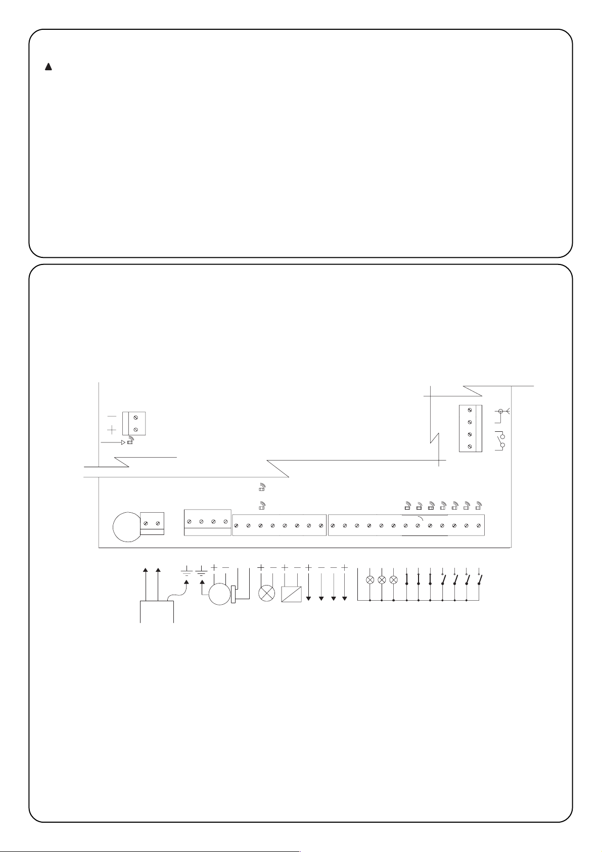
38
LED BATTERIE
CLIGNOTANT 24Vcc
Max 25W
2
ALIMENTATION
SECTEUR
1
ENCODEUR
MOTEUR
TERRE SECTEUR
TERRE MOTEUR
5
3
4
8
9
7
6
M
19
COR
PHOTO-TEST 24 Vcc
Max 200mA
BLOC. ÉLECT. 24Vcc
Max 500 mA
SERVICES 24 Vcc
SCA
COMMUN 24Vcc
Max 200mA
14
12
11
13
10
18
161517
PHOTO2
MAN
OUV. PARTIELLE
OUVRE
FERME
PHOTO
HALTE
PAS-À-PAS
24
23
20
21
22
27
26
25
F1
BATTERIES
LED ENCODEUR
LED DÉBRAYAGE
PAS-À-PAS
FERME
OUV. PARTIELLE
PHOTO2
PHOTO
HALTE
OUVRE
44
DEUXIÈME
CANAL RADIO
ANTENNE
42
41
43
2.4) Schema électrique
2.3 Connexions electriques
Pour garantir la sécurité de l’opérateur et pour éviter
d’endommager les composants, quand on effectue les
connexions ou qu’on branche le récepteur radio, l’armoire
de commande ne doit pas être alimentée par le secteur
et/ou les batteries
Pour effectuer les connexions se référer au schéma
électrique (paragraphe 2.4) en tenant compte que:
• Alimenter l’armoire de commande avec un câble de 3 x 1,5 mm
2
(phase, neutre et terre); si la distance entre l’armoire et la
connexion à l’installation de terre dépasse les 30 m, il est
nécessaire de prévoir une prise de terre à proximité de l’armoire.
• Pour la connexion avec l’opérateur SUMO utiliser un câble de
3x2,5 mm
2
(pour plus de 10 m utiliser 4 mm2) pour le moteur et un
câble de 2 x 0,75 mm
2
pour l’encodeur.
• Pour la connexion du clignotant et du blocage électrique, nous
conseillons d’utiliser un câble d’une section minimum d’1 mm
2
.
• Dans les connexions de la partie à très basse tension de sécurité
utiliser des câbles de section minimum de 0,25 mm
2
; (utiliser des
câbles blindés si la longueur dépasse les 30 m en connectant le
conducteur externe à la terre seulement du côté de l’armoire).
• Faire attention aux dispositifs avec polarité (clignotant, blocage
électrique, sortie photo-test, services, batterie, etc.).
• Les entrées de type Normalement Fermé (NF), si elles ne sont pas
utilisées, doivent être shuntées avec “Commun 24 Vcc” ; les
entrées de type Normalement Ouvert (NO), si elles ne sont pas
utilisées, doivent être laissées libres.
• Les contacts doivent être absolument de type mécanique et libres
de toute puissance ; les connexions à étage type "PNP", "NPN" ,
"Open Collector" etc. ne sont pas admises.
!
Page 39

F39F
2.5 Description des connexions
Bornes Fonctions Description
1-2 Phase - Neutre = Alimentation de secteur
3 Terre = Connexion de l’armoire vers la terre
4 Terre = Connexion à la terre du moteur
5-6 Moteur = Alimentation moteur 36 Vcc
7-8 Encodeur = Entrée Encodeur moteur
9-10 Clignotant = Sortie clignotant 24 Vcc max. 25 W
11-12 Bloc. élect./Ventouse = Sortie blocage électrique/ventouse 24 Vcc max. 500 mA
13-14 Photo-test = Sortie photo-test
15-16 24 Vcc = Alimentation services 24 Vcc max. 200 mA
17 Commun = Commun pour toutes les entrées
18 Sca = Sortie Voyant porte ouverte (actif avec porte ouverte, éteint avec porte fermée, clignotant
lent dans la manœuvre d’ouverture, rapide dans la manœuvre de fermeture)
19 Cor = Sortie Éclairage automatique (s’active au début de la manœuvre et reste actif pendant
encore 60 s après la fin de la manœuvre)
20 Man = Sortie Voyant maintenance
21 Halte = Entrée avec fonction de HALTE (Urgence, blocage ou sécurité extrême)
22 Photo = Entrée pour dispositifs de sécurité (Photocellules, barres palpeuses avec pneumatiques)
avec intervention dans la manœuvre de fermeture
23 Photo 2 = Entrée pour dispositif de sécurité (Photocellules, barres palpeuses pneumatiques) avec
intervention dans la manœuvre d’ouverture
24 Pas-à-Pas = Entrée avec fonctionnement cyclique Ouvre - Stop - Ferme - Stop
25 Ouvre =
Entrée pour mouvement en ouverture avec fonctionnement cyclique Ouvre-Stop-Ouvre-Stop
26 Ferme =
Entrée pour mouvement en fermeture avec fonctionnement cyclique Ferme-Stop-Ferme-Stop
27 Ouv. partielle = Entrée avec fonctionnement cyclique Ouv. Partielle - Stop - Ferme - Stop
41-42 2° C. Radio = Sortie deuxième canal récepteur radio
43-44 Antenne = Entrée antenne récepteur radio
+ - Batterie = Connexion batterie 24 volts
Page 40

40
23
22
16
15
17
5423
RX
1
FOTO 2
TX
21
16
23
15
17
13
14
4231
RX
5
14
13
TX
21
FOTO 2
RX
54231
16
FOTO
TX
21
23
22
16
15
4231
RX
5
17
15
22
17
13
14
13
23
13
23
14
13
TX
21
FOTO
16
15
23
17
22
16
15
17
13
14
14
13
4231
RX
5
4231
RX
5
TX
21
TX
21
FOTO 2
FOTO
12 43251
5431221
17
22
23
16
15
RX
RXTX
TX
FOTO
FOTO 2
14
13
2.6) Foto-test
La fonction Photo-test constitue une excellente solution en termes
de fiabilité pour les dispositifs de sécurité et permet d’atteindre, en
ce qui concerne l’ensemble armoire + dispositifs de sécurité, la
"catégorie 2" selon la norme UNI EN 954-1 (éd. 12/1998).
Pour réaliser cette solution, il faut connecter les photocellules
suivant l’indication de l’une des figures 3A, 3B ou 3C, et placer le
Dip-Switch 7 sur On (activation photo-test).
Fig. 3A Connexion photo-test avec les photocellules Photo et Photo2
Fig 3B Connexion photo-test avec seulement la photocellule Photo
Fig 3C Connexion photo-test avec seulement la photocellule Photo2
Quand une manœuvre est commandée, en premier lieu, la logique
de commande contrôle que tous les récepteurs concernés donnent
leur accord, puis la sortie photo-test est éteinte et la logique vérifie
que tous les récepteurs signalent le fait, en niant leur accord ; enfin
la sortie photo-test est réactivée et la logique vérifie de nouveau
l’accord de la part de tous les récepteurs. Si au cours de la
séquence que nous venons de décrire la logique de commande
détecte un dispositif en avarie ou un câble en court-circuit, etc., la
manœuvre n’est pas exécutée.
PHOTO
PHOTO 2
PHOTO
PHOTO PHOTO
PHOTO 2
PHOTO 2 PHOTO 2
Page 41
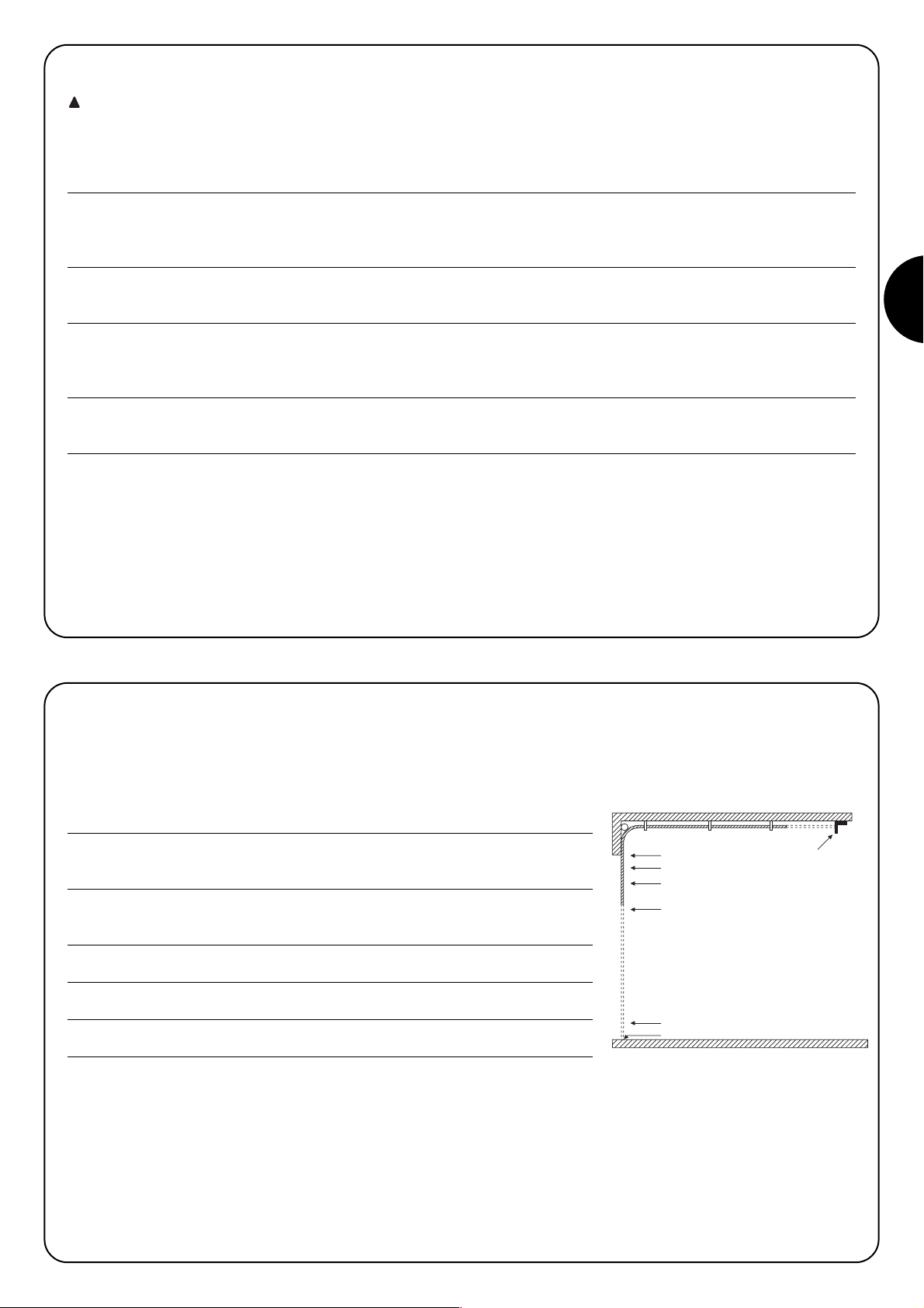
F
41
Une fois que les connexions sont terminées, il est bon d’effectuer une vérification générale, à savoir:
• Alimenter l’armoire de commande et vérifier immédiatement que la tension de secteur est présente sur les bornes 1-2, et que la tension
est d’environ 28 Vcc sur les bornes 15-16 (sortie services). Si les valeurs sont différentes, couper immédiatement le courant et vérifier plus
attentivement les connexions et la tension d’alimentation.
• Environ deux secondes après l’allumage, la led “OK” doit clignoter régulièrement au rythme d’un clignotement à la seconde en indiquant
ainsi le fonctionnement correct de l’armoire de commande.
• Vérifier que les led relatives aux entrées avec contacts de type Normalement Fermé (“Halte”, “Photo” et “Photo2”) sont allumées (sécurités
actives) tandis que les led relatives aux entrées de type Normalement Ouvert sont éteintes (aucune commande présente); si ce n’est pas
le cas, contrôler les connexions et l’efficacité des différents dispositifs.
• Vérifier le fonctionnement correct de tous les dispositifs de sécurité présents dans l’installation (arrêt d’urgence, photocellules, barres
palpeuses pneumatiques etc.), à chaque fois qu’ils interviennent les led correspondantes “Halte”, “Photo” ou “Photo2” doivent s’éteindre.
• Vérifier que le mouvement du moteur s’effectue dans le bon sens, à savoir:
• débloquer le moteur et vérifier que la led débrayage située sur la carte est allumée ;
• positionner à la main la porte dans une position telle qu’elle peut bouger aussi bien en ouverture qu’en fermeture;
• rebloquer le moteur et vérifier que la led débrayage est éteinte;
• presser la touche “Ferme” (réf. K - Fig. 1) et vérifier que la porte bouge dans le sens de la fermeture;
• si la manœuvre effectuée est une manœuvre d’ouverture, presser de nouveau la touche Ferme pour arrêter le mouvement, couper
l’alimentation et inverser les deux fils du moteur;
• indépendamment du sens du mouvement il est bon d’arrêter immédiatement la manœuvre en pressant de nouveau la touche “Ferme”.
Si la vérification des connexions a eu un résultat positif, on peut commencer la phase de recherche des butées de fin de course mécaniques.
L’opération est nécessaire parce que l’armoire de commande A924 doit mesurer l’espace parcouru par le moteur, en termes de nombre
d’impulsions de l’encodeur, pour porter la porte de la position de fermeture maximum (point 0) à celle d’ouverture maximum (point 1).
Le point 0 et le point 1 servent de référence pour tous les autres points indiqués dans la représentation graphique de la Fig. 4
POINT 0 : c’est le point où se trouve la porte sectionnelle dans la situation de fermeture,
il coïncide avec la butée de fin de course mécanique (généralement le sol).
POINT 1: c’est le point où se trouve la porte sectionnelle dans la situation d’ouverture
maximum, correspondant avec les butées de fin de course mécaniques
d’ouverture (point M).
POINT A: c’est la position où l’on désire que la porte s’arrête dans la manœuvre
d’ouverture (ne coïncide pas nécessairement avec les butées de fin de course
mécaniques en ouverture).
POINT B: c’est la position où l’on désire que la porte s’arrête dans la manœuvre
d’ouverture partielle.
POINT RA: c’est la position où l’on désire que la porte commence à ralentir dans la
manœuvre d’ouverture normale.
POINT RC: c’est la position où l’on désire que la porte commence à ralentir en fermeture.
La recherche des butées de fin de course mécaniques peut s’effectuer à travers la recherche initiale, la recherche automatique ou la
programmation manuelle. Après la “recherche initiale” ou la “recherche automatique”, si on le souhaite, on peut modifier avec la
programmation manuelle un ou plusieurs points trouvés en automatique, à l’exclusion des points 0 et 1 qui servent de référence pour tous
les autres.
3) PROGRAMMATION
2.7) Verification des connexions
Les opérations qui suivent vous porteront à agir sur des
circuits sous tension, certaines parties sont soumises à la
tension de secteur et donc très dangereuses !
Faites très attention aux opérations que vous effectuez et
n’opérez jamais seuls!
!
1
A
RA
B
RC
0
M
Page 42

42
3.1)
Recherche initiale des butées de fin de course mécaniques
La procédure "recherche initiale des butées de fin de course mécaniques” est effectuée automatiquement comme première manœuvre après l’installation.
Tableau “A” Pour activer la recherche initiale des butées de fin de course mécaniques:
1. Débloquer le moteur et positionner à la main la porte dans une position telle qu’elle peut bouger aussi bien en ouverture
qu’en fermeture; bloquer le moteur.
2. Presser brièvement la touche “Ouvre” (réf. I - Fig. 1) ou “Ferme” (réf. K - Fig. 1) présente sur la carte ou donner une impulsion
de commande sur les entrées et attendre que l’armoire de commande effectue une fermeture lente jusqu’au point 0, une
ouverture lente jusqu’au point 1 et une fermeture rapide jusqu’au point 0.
Note. Si après la commande la première manœuvre est une ouverture, donner une autre commande pour arrêter la
procédure et inverser la polarité du moteur.
3. Quand la séquence décrite ci-dessus est terminée, la logique de commande détermine, avec une opération mathématique,
le point A (ouverture désirée) à quelques centimètres de l’ouverture maximum, le point B (ouverture partielle) à environ 3/4
du point A, ainsi que les points RA et RC nécessaires pour les ralentissements.
4. La procédure de “recherche initiale” des butées de fin de course mécaniques est terminée et l’opérateur est prêt à l’emploi.
Note 1. Si durant la “Recherche Initiale” des butées de fin de course mécaniques il y a intervention de l’un des dispositifs de sécurité ou
une autre impulsion de commande, le mouvement de la porte sera immédiatement arrêté et il sera donc nécessaire de répéter les opérations
décrites ci-dessus.
3.2) Recherche automatique des butées de fin de course mécaniques
En alternative à la “Recherche Initiale”, on peut activer à tout moment la “Recherche automatique des butées de fin de course mécaniques”.
La procédure effectue automatiquement la recherche des butées de fin de course mécaniques (point 0 et point 1) suivant les mêmes
modalités que celles qui sont décrites dans la recherche initiale
Tableau “B” Pour activer la recherche automatique des butées de fin de course mécaniques:
1. Positionner les dip-switchs de la façon suivante:
2. Débloquer le moteur et positionner à la main la porte dans une position telle qu’elle peut bouger aussi bien en ouverture
qu’en fermeture; bloquer le moteur.
3. Presser la touche Ferme (réf. K - Fig. 1) et attendre que l’armoire de commande effectue une fermeture lente jusqu’au point
0, une ouverture lente jusqu’au point 1 et une fermeture rapide jusqu’au point 0.
Note.
Si après la commande la première manœuvre est une ouverture, donner une autre commande pour arrêter la
procédure et inverser la polarité du moteur
.
4.
P
artant de ces points, la logique de commande détermine, avec une opération mathématique, le point A (ouverture désirée)
à quelques centimètres de l’ouverture maximum, le point B (ouverture partielle) à environ 3/4 du point A, ainsi que les points
RA et RC nécessaires pour les ralentissements.
5. La procédure de “Recherche Initiale” des butées de fin de course mécaniques est terminée et l’opérateur est prêt à l’emploi.
(Positionner les dip-switchs “fonctions” de la manière désirée.)
Nota1. Si durant la “Recherche Automatique” des butées de fin de course mécaniques un événement extérieur se vérifie (nouvelle pression
d’une touche, intervention de Photo ou impulsion di commande) le mouvement de la porte sera immédiatement arrêté et il sera donc
nécessaire de répéter les opérations.
3.3) Procédure de mémorisation
Dans les paragraphes qui suivent, à la fin des séquences de programmation de certains paramètres, on trouvera plusieurs fois l’invitation à
effectuer la "Procédure de mémorisation". Cette opération sert à transférer dans la mémoire permanente, présente sur la logique, la
valeur du paramètre que l’on désire programmer.
Tableau “C” Pour effectuer la procédure de mémorisation:
1. Presser pendant au moins 3 s la touche “Mémoire” (réf. J - Fig. 1), au bout des 3 s la led “OK” clignote rapidement.
2. Relâcher la touche “Mémoire”, la led “OK” (réf. R - Fig. 1) continue à clignoter rapidement pendant encore 3 s.
3. Dans les trois secondes qui suivent, presser simultanément pendant un court instant les deux touches “Ouvre” et “Ferme”
(réf. I et K - Fig. 1) ; à la pression simultanée des deux touches, la led “OK” s’éteint.
4. Relâcher les deux touches “Ouvre” et “Ferme” (réf. I et K - Fig. 1) ; la led “OK” (réf. R - Fig. 1) s’allume pendant 2 s environ
en confirmant ainsi que la procédure de mémorisation du paramètre sélectionné a été effectuée correctement.
12345678910 11 12
Page 43

F
43
3.4) Programmation manuelle des butées de fin de course mécaniques
La procédure prévoit l’insertion manuelle de tous les points indiqués dans la Fig.4 , en respectant l’ordre indiqué dans le tableau ci-dessous;
en particulier le point 0 est le point de référence, il doit être programmé en premier et jamais plus déplacé.
Tableau “D” Pour programmer manuellement les différents points:
1. Positionner les dip-switchs dans l’une des manières indiquées suivant le paramètre à mémoriser.
POINT 0: Butée de fin de course mécanique en fermeture
POINT RC: Position où commence le ralentissement dans la manœuvre
de fermeture
POINT B: Position d’arrêt dans la manœuvre d’Ouverture partielle
POINT RA: Position où commence le ralentissement dans la
manœuvre d’ouverture normale
POINT A: Position d’arrêt dans la manœuvre d’Ouverture normale
POINT 1: Butée de fin de course mécanique en ouverture
2.
Presser et maintenir enfoncée la touche Ouvre (réf. I - Fig. 1) ou Ferme (réf. K - Fig. 1) sur la carte jusqu’à l’atteinte du point désiré
Note. Presser la touche Mémoire (réf. J - Fig. 1)si l’on désire accélérer le mouvement.
3. Quand le point est atteint, relâcher les touches et exécuter la “Procédure de mémorisation” (parag. 3.3)
Note1. En alternative à la programmation manuelle de tous les points, il est possible de mémoriser seulement les points 0, A et 1 et d’avoir
le mouvement de la porte avec les points B, RA et RC déterminés de manière automatique par la logique de commande.
3.5) Programmation point blocage electrique
Quand un fonctionnement de type blocage électrique est attribué à la sortie ELB (voir switch 8 au paragraphe 5) il est possible de
programmer le seuil au-delà duquel la sortie s’éteint.
Tableau “E” Pour programmer le point blocage électrique:
1. Positionner les dip-switchs de la façon suivante:
2. Presser la touche “Ouvre” (réf. I - Fig. 1) ou “Ferme” (réf. K - Fig. 1) jusqu’à l’atteinte du point désiré.
Note. Presser la touche “Mémoire” (réf. J – Fig. 1) si l’on désire accélérer le mouvement.
3. Quand le point est atteint relâcher les touches et exécuter la “Procédure de mémorisation” (paragraphe 3.3)
12345678910 11 12
12345678910 11 12
12345678910 11 12
12345678910 11 12
12345678910 11 12
12345678910 11 12
12345678910 11 12
Page 44

44
3.6) Programmation temps de pause
Quand la fonction de fermeture automatique est sélectionnée, après une manœuvre d’ouverture un temporisateur ayant pour fonction de
contrôler le Temps de Pause est activé, une manœuvre de fermeture s’active automatiquement quand ce temps de pause s’est écoulé. Ce
temps, s’il n’a jamais été programmé, est fixé par la logique de commande à 30 s mais avec la procédure spécifique il peut être programmé
à n’importe quelle valeur comprise entre 1 et 1023 s (environ 17 minutes).
Tableau “F” Pour programmer le Temps de Pause:
1. Positionner les Dip-Switchs de la façon suivante:
2. Sélectionner le temps désiré avec le Dip-Switch à 10 voies en tenant compte que: Exemple : temps de pause 25 s
Dip-switch 1 On active la pause pendant 1 s 25 = 16+8+1
Dip-switch 2 On " 2 "
positionner sur On les Dip-Switchs 5, 4 et 1
Dip-switch 3 On " 4 "
Dip-switch 4 On " 8 "
Dip-switch 5 On " 16 "
Dip-switch 6 On " 32 "
Dip-switch 7 On " 64 "
Dip-switch 8 On " 128 "
Dip-switch 9 On " 256 "
Dip-switch 10 On " 512 "
Si l’on place sur On plus d’un Dip-Switch, le temps de pause sélectionné est égal à la somme des temps de pause de
chaque Dip-Switch;
3. Exécuter la “Procédure de mémorisation” (paragraphe 3.3)
3.7 Effacement de la memoire
Tous les paramètres programmables sont enregistrés dans une mémoire de type permanente qui conserve les informations même en cas
de coupure de courant; il peut se révéler nécessaire de devoir effacer en bloc tout le contenu de la mémoire.
Tableau “G” Pour effacer le contenu de la mémoire:
1. Positionner les Dip-Switchs comme l’indique la figure:
2. Exécuter la “procédure de mémorisation” (voir paragraphe 3.3) qui dans ce cas sert à confirmer l’effacement.
Note. Avec la mémoire remise à zéro, c’est comme si l’opérateur n’avait jamais été installé et donc le mouvement normal de la porte ne
sera pas possible ; dans ce cas, la première commande qui arrivera aux entrées ou la pression des touches “Ouvre” ou “Ferme” activera
immédiatement une procédure de “Recherche initiale des butées de fin de course mécaniques”
Note 1. Cette opération ne provoque pas l’effacement du nombre de manœuvres exécutées et le nombre de manœuvres programmées.
3.8 Réglages
Une fois que la phase de programmation est terminée, on peut
passer à l’exécution des quelques réglages indispensables pour un
fonctionnement correct et sûr de l’automatisme
12345678910 11 12
12345678910 11 12
12345678910 11 12
Page 45
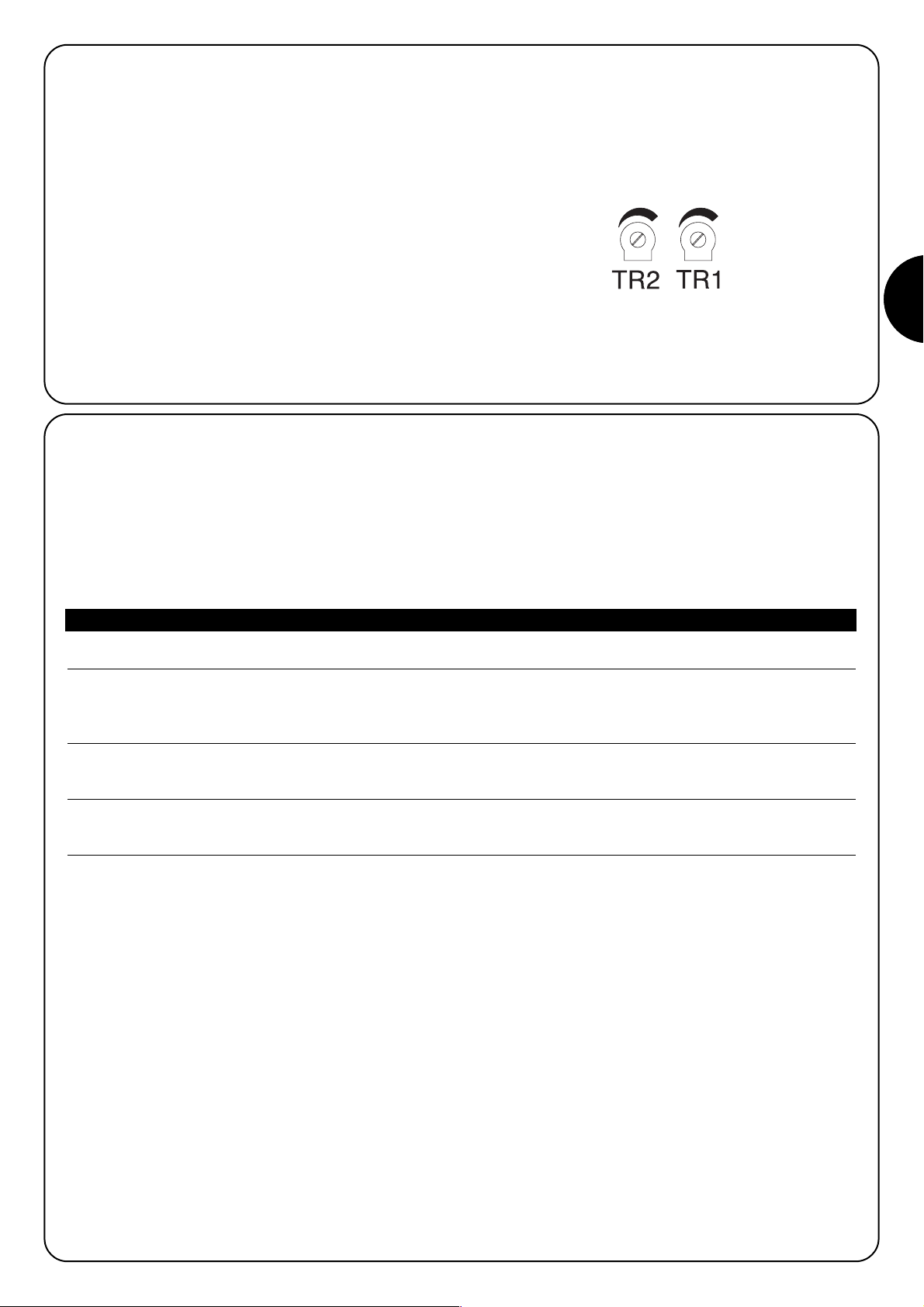
F45F
3.8.1) Réglage ampèremétrique
Pour limiter les forces en jeu dans le mouvement, condition imposée
par les normes, l’armoire de commande dispose de deux trimmers
TR2 (réf. C - Fig. 1) et TR1 (réf. D - Fig. 1) qui permettent de modifier
le seuil d’intervention de la fonction ampèremétrique respectivement
dans la manœuvre d’ouverture et de fermeture. Si un obstacle est
détecté durant le mouvement de la porte, la logique de commande
effectue un arrêt et si le fonctionnement “Semi-automatique” ou
“Automatique” est activé, elle commence une manœuvre dans le
sens opposé.
Dans le cas d’une intervention de la fonction ampèremétrique dans
la manœuvre de fermeture, la logique de commande provoque une
inversion et la manœuvre d’ouverture, si elle n’est pas interrompue,
se termine avec la porte contre la butée de fin de course mécanique
d’ouverture - point 1 (reconfirmation de la position).
Pour augmenter encore plus le niveau de sécurité, si la fonction
ampèremétrique intervient trois fois de suite sans que la porte
parvienne à une fermeture régulière, on a un stop précédé d’une
brève inversion.
TR2 = Réglage ampèremétrique manœuvre ouverture.
TR1 = Réglage ampèremétrique manœuvre fermeture.
3.8.2) Réglage vitesse
Pour limiter l’énergie cinétique lors de l’impact contre un obstacle, en plus du réglage du seuil d’intervention de la fonction ampèremétrique,
on peut réduire la vitesse de la porte durant le fonctionnement normal.
Le réglage de la vitesse peut être effectué:
• avec le fonctionnement “Manuel” seulement quand le moteur est arrêté,
• avec le fonctionnement “Semi-automatique” ou “Automatique” avec le moteur arrêté ou en mouvement (sauf durant les phases
d’accélération et de ralentissement).
Tableau “H” Pour régler la vitesse:
1. Presser et maintenir enfoncée la touche “Mémoire” sur la carte (réf. J - Fig. 1).
2. Une seconde après…..
♦ presser et maintenir enfoncée la touche “Ferme” (réf. K - Fig. 1) pour diminuer la vitesse ou
♦ presser et maintenir enfoncée la touche “Ouvre” (réf. I - Fig. 1) pour augmenter la vitesse
3. Dès que la vitesse a atteint la valeur désirée, relâcher les touches (de cette manière, la vitesse réglée est automatiquement
mémorisée).
Note. Le système de réglage est efficace tant que les valeurs limites min. ou max. auxquelles correspondent les vitesses figurant dans le
manuel d’instructions du moteur ne sont pas atteintes ; quand ces limites sont atteintes, la led le signale en restant toujours allumée quand
la valeur maximum est atteinte et vice versa, toujours éteinte quand la valeur minimum est atteinte.
Page 46

46
L’essai de fonctionnement de l’automatisme doit être effectué par du personnel qualifié et expérimenté qui devra se
charger d’établir les essais prévus en fonction du risque présent.
L’essai de fonctionnement est la partie la plus importante de toute la phase de réalisation de l’automatisme. Chaque composant, comme le
moteur, l’arrêt d’urgence, les photocellules etc., peut nécessiter une phase d’essai spécifique et pour cela, nous conseillons de suivre les
procédures indiquées dans les manuels d’instructions respectifs.
Pour l’essai de fonctionnement de l’armoire de commande A924 exécuter les opérations suivantes:
1. Positionner les Dip-Switchs de la façon suivante:
(toutes les fonctions désactivées et fonctionnement semi-automatique))
2. Presser la touche “Ouvre” (réf. I - Fig. 1) et vérifier que:
• le clignotant s’active
• une manœuvre d’ouverture commence avec la phase d’accélération
• le mouvement s’arrête, précédé par la phase de ralentissement, quand la porte a atteint le point A.
3. Presser la touche “Ferme” (réf. K - Fig. 1) et vérifier que:
• le clignotant s’active
• une manœuvre de fermeture commence
• le mouvement s’arrête, quand la porte a atteint le point 0.
4. Commander une manœuvre d’ouverture et vérifier que l’intervention d’un dispositif connecté à l’entrée:
• “Halte”, provoque l’arrêt immédiat du mouvement
• “Photo”, n’a aucun effet
• “Photo2”, provoque l’arrêt et l’inversion de la manœuvre
5. Faire démarrer une manœuvre de fermeture et vérifier que l’intervention d’un dispositif connecté à l’entrée:
• “Halte”, provoque l’arrêt immédiat du mouvement
• “Photo”, provoque l’arrêt et l’inversion de la manœuvre
• “Photo2”, n’a aucun effet
6. Solliciter un dispositif connecté à l’entrée:
• “Halte”, et vérifier qu’en activant une entrée de commande aucune manœuvre ne démarre
• “Photo”, et vérifier qu’en activant une entrée de commande qui provoque une fermeture, la manœuvre ne démarre pas
• “Photo2”, et vérifier qu’en activant une entrée de commande qui provoque une ouverture, la manœuvre ne démarre pas
7. Durant le mouvement, en ouverture comme en fermeture, empêcher le mouvement de la porte avec un obstacle et vérifier
que la manœuvre s’inverse avant de dépasser la force prévue par les normes.
8. Vérifier que l’activation des entrées (si elles sont connectées) provoque un pas dans la séquence
• pour l’entrée “Pas-à-pas”: Ouvre – Stop – Ferme –Stop,
• pour l’entrée “Ouvre”: Ouvre – Stop – Ouvre – Stop,
• pour l’entrée “Ferme”: Ferme - Stop- Ferme – Stop,
• pour l’entrée “Ouverture Partielle”: Ouv. Partielle – Stop –Ferme – Stop.
5) Fonctions sélectionnables
Avec les dip-switchs de programmation sur Off, les dip-switchs fonctions permettent de sélectionner les différents modes de fonctionnement
et fonctions comme le détaille le tableau ci-après:
Switch 1-2 Off Off = Fonctionnement “Manuel” c’est-à-dire Homme Présent
On Off = Fonctionnement “Semi-automatique”
Off On = Fonctionnement “Automatique” c’est-à-dire fermeture automatique
On On = Fonctionnement “Automatique + Ferme toujours”
Switch 3 On = Fonctionnement collectif <Pas disponible en mode Manuel>
Switch 4 On = Préclignotement 5 s (2 s en manuel)
Switch 5 On = Referme 5 s après Photo en automatique ou referme après Photo en semi-automatique
Switch 6 On = Sécurité Photo aussi en ouverture
Switch 7 On = Activation Photo-test
Switch 8 On = Ventouse/Blocage électrique (On = ventouse Off = blocage électrique)
Switch 9 On = Feu en mode “à sens unique”
Switch 10 On = Feu “dans les deux sens”
Note. Naturellement quand le switch correspondant est sur "Off" la fonction décrite n’est pas active
4) Essai de fonctionnement
!
12345678910 11 12
Page 47

F
47
5.1) Description des fonctions
Fonctionnement Manuel. Le mouvement est exécuté seulement en présence de la commande. Le mouvement s’arrête dès que la
commande cesse ou après l’intervention d’un dispositif de sécurité (Halte, Photo ou Photo2) ou de la fonction ampèremétrique. Une fois
que le mouvement s’est arrêté, il faut cesser la commande en entrée avant de pouvoir commencer un nouveau mouvement.
Fonctionnement semi-automatique et automatique. En “Semi-automatique” ou “Automatique” suite à une impulsion de commande,
tout le mouvement est effectué jusqu’à ce que le point prévu soit atteint. Une deuxième impulsion sur la même entrée qui a commencé le
mouvement provoque un Stop. Si dans une entrée de commande, au lieu d’une impulsion on maintient un signal continu, on provoque un
état de priorité dans lequel les autres entrées de commande sont désactivées (utile pour connecter une horloge en ouverture par exemple).
Durant une manœuvre l’intervention de la fonction ampèremétrique ou d’une photocellule impliquée dans la direction du mouvement
(“Photo” en fermeture, “Photo2” en ouverture) provoque l’inversion.
Dans le mode de fonctionnement Automatique, après une ouverture, on a une pause puis une fermeture.
Si “Photo” intervient durant la pause, le temporisateur sera remis à zéro avec un nouveau temps ; si par contre c’est l’entrée Halte qui
intervient durant la pause, la fonction de refermeture est effacée et on passe à un état de Stop.
Fonction “Ferme Toujours”, fait démarrer automatiquement une manœuvre de fermeture, précède de 5 s de préclignotement si au retour
du courant, le système détecte la porte ouverte.
Fonctionnement Collectif. Dans le fonctionnement “Collectif”, une manœuvre d’ouverture ne peut pas être interrompue par des
impulsions de commande à l’exception de celles qui provoquent une fermeture. Dans le mouvement en fermeture une nouvelle impulsion
de commande provoque l’arrêt et l’inversion du mouvement en ouverture
.
Préclignotement. Une impulsion de commande active d’abord le clignotant puis, au bout de 5 s (2 s en mode manuel) la manœuvre
commence.
Referme 5 s après Photo (en mode automatique) ou referme après Photo (en mode semi-automatique). En automatique,
une intervention de photo dans la manœuvre d’ouverture ou de fermeture réduit le temps de pause à 5 s indépendamment du temps de
pause programmé. En mode semi-automatique, une intervention de Photo dans la manœuvre de fermeture active la fermeture automatique
avec le temps de pause programmé.
.
Sécurité Photo également en ouverture. Avec cette fonction, l'intervention du dispositif de sécurité Photo provoque une interruption
du mouvement aussi en ouverture, si le fonctionnement “Semi-automatique” ou “Automatique” est sélectionné, juste après la libération de
la photocellule “Photo”, on aura la reprise du mouvement en ouverture.
Activation Photo-test. Cette fonction permet d’exécuter au début de chaque manœuvre un contrôle de l’efficacité de toutes les
photocellules, en augmentant de cette manière la sécurité de l’installation. Pour plus de détails, voir le paragraphe 2.6 “Photo-test”
Ventouse/blocage électrique
La fonction permet d’attribuer à la sortie Elb (bornes 11 et 12) un fonctionnement de type:
• blocage électrique (Switch 8 Off) - la sortie s’active dans la manœuvre d’ouverture partant de la porte fermée et reste active jusqu’à ce
que la porte ait dépassé le point blocage électrique (programmable, voir paragraphe 3.5);
•
ventouse (Switch 8 On) - la sortie s’active à al fin du mouvement de fermeture et reste active pendant tout le temps que la porte est fermée
.
Feu en mode sens unique. Dans ce mode, la sortie SCA est active avec la porte ouverte et durant la manœuvre d’ouverture, elle reste
allumée, tandis qu’elle se désactive dans la manœuvre de fermeture et quand la porte est fermée. Dans ce mode, on peut appliquer à la
sortie une lampe de couleur verte qui indique, quand elle est allumée, que le passage est libre
.
Feu dans les deux sens. En positionnant le switch 10 sur On, indépendamment du switch 9, on active la fonction “feu dans les deux sens”;
la logique de commande subit les modifications suivantes: l’entrée “Ouvre” devient “Pas-à-pas2”, tandis que les deux sorties “Éclairage
automatique” (COR) et Voyant porte ouverte (SCA) deviennent feu vert pour un sens et feu Vert pour l’autre, comme l’indique la Fig. 5. Pour
chaque sens de marche, il y a une commande différente pour l’ouverture: “Pas-à-pas” (PP) pour entrer et “Pas-à-pas 2” (PP2) pour sortir ; le
système est ensuite complété par l’installation de deux feux avec signalisation Rouge et Verte, connectés aux SCA et COR.
Normalement, les deux sorties SCA et COR sont éteintes et par conséquent, les feux le sont eux aussi ; quand une commande est donnée
avec PP pour entrer, la manœuvre d’ouverture commence et simultanément la sortie Sca s’active en allumant le feu vert à l’entrée et le feu
rouge à la sortie. Si par contre la commande pour l’ouverture est donnée par PP2, la sortie Cor s’active en allumant le feu vert à la sortie
et le feu rouge à l’entrée. Le feu restera allumé pendant toute la phase d’ouverture et pendant l’éventuelle pause ; dans la phase de
fermeture, les feux vert et rouge seront activés tous les deux pour indiquer qu’il n’y a plus de priorité dans le passage.
Les deux sorties peuvent commander directement des petites lampes à 24 Vcc pour un total par sortie de 10 W max. S’il est nécessaire
d’utiliser des lampes d’une puissance supérieure, il faudra utiliser des relais pilotés par les sorties de l’armoire de commande qui
commandent à leur tour les lampes du feu.
Page 48
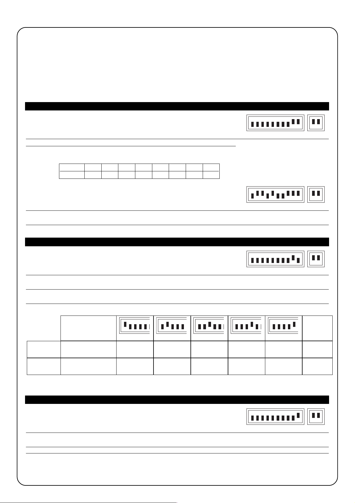
48
6) Maintenance
La carte, en tant que partie électronique, n’a besoin d’aucune maintenance particulière, toutefois, il est bon de vérifier périodiquement (au moins tous
les 6 mois) le fonctionnement correct de la carte et les dispositifs connectés en refaisant complètement l’essai de fonctionnement (voir Chapitre 4).
Pour planifier les interventions de maintenance de toute l’installation, l’armoire de commande est dotée d’un compteur de manœuvres qui
augmente la valeur à chaque ouverture. L’augmentation est signalée par un clignotement du voyant maintenance (MAN). La valeur du
compteur est constamment comparée à un seuil d’alarme (programmable par l’installateur) et à un seuil d’alerte (placé automatiquement
égal au seuil d’alarme moins 6% environ). Quand le nombre de manœuvres effectuées dépasse le seuil d’alerte, le voyant maintenance
clignote seulement durant la manœuvre tandis que si l’on dépasse le seuil d’alarme, il clignote de manière permanente (avec le moteur arrêté
et durant le mouvement) pour indiquer qu’il faut procéder à la maintenance.
Le seuil d’alarme peut être programmé d’une valeur minimum de 200 à une valeur maximum de 50800 manœuvres par multiples de 200.
Tableau “I” Pour programmer le seuil d’alarme:
1. Positionner les Dip-Switchs de la façon suivante:
2. Diviser le nombre des manœuvres à programmer par 100 et par 2. Exemple: nombre de manœuvres
3.
Identifier dans le tableau la combinaison de dip-switchs dont la somme des valeurs
à programmer 30000
est identique au nombre trouvé au point 2 et positionner les Dip-Switchs correspondants sur on.
Résultat après la division: 150
150 = 128 + 16 + 4 + 2,
Dip-Switch 8, 5, 3 et 2 sur On
4. Exécuter la “Procédure de mémorisation” (voir paragraphe 3.3).
Après avoir programmé le seuil d’alarme, on peut le visualiser pour contrôler que l’opération a été correctement exécutée.
Tableau “L” Pour visualiser le seuil d’alarme:
1. Positionner les Dip-Switchs de la façon suivante:
2. Positionner les Dip-Switchs 1 sur On (2,3,4 e 5 in Off), compter le nombre de clignotements de la led “OK” et reporter le
nombre de clignotements sur une feuille (s’il y en a 10 écrire 0)
3. Répéter l’opération avec les Dip-Switchs 2, 3, 4 et 5
4. Reconstruire le nombre des manœuvres comme l’indique l’un des deux exemples ci-dessous:
Avec la même procédure il est possible de visualiser également le nombre de manœuvres effectuées;
Tableau “M” Pour visualiser le nombre de manœuvres effectuées:
1. Positionner les Dip-Switchs de la façon suivante:
2. Répéter le comptage des clignotements de la led “OK” avec les Dip-Switchs 1,2,3,4,5 comme l’indique l’exemple 1 ou 2.
Note. À chaque fois que le seuil d’alerte est programmé, le nombre de manœuvres effectuées est automatiquement effacé.
Dip Switch Sw1 Sw2 Sw3 Sw4 Sw5 Sw6 Sw7 Sw8
Valeur 1248163264128
Configuration
Dip switch
Nombre de
manœuvres
Exemple
n° 1
Nb de clignotements
Led OK
10
1
1
4
2
10
10
10
4
7
1.204
Exemple
n° 2
Nb de clignotements
Led OK
14.007
12345678910 11 12
12345678910 11 12
12345678910 11 12
123456
123456
123456 123456 123456
12345678910 11 12
Page 49

F
49
6.1) Mise au rebut
Ce produit est constitué de différents types de matériaux dont
certains peuvent être recyclés. Informez-vous sur les méthodes de
recyclage ou de mise au rebut du produit en suivant les normes en
vigueur sur le plan local.
Certains composants électroniques peuvent contenir
des substances polluantes, ne les abandonnez pas dans la
nature.
L’armoire de commande contient un connecteur pour la connexion
d’un récepteur radio (accessoire en option) qui permet d’agir sur
l’entrée de Pas-à-pas et de commander de cette manière l’armoire
à distance avec un émetteur. L’éventuel contact libre du deuxième
canal est disponible sur les bornes 41-42.
Avant de connecter le récepteur, couper l’alimentation électrique et
déconnecter les éventuelles batteries puis connecter le récepteur
avec les composants tournés vers le microprocesseur de l’armoire
de commande.
L’armoire de commande dispose d’un transformateur d’une puissance en mesure de supporter l’énergie requise par le moteur et par la carte
électronique quand le tout est alimenté directement par le secteur. Si l’on désire que l’automatisme fonctionne également en cas de coupure
du courant, il suffit de connecter les batteries prévues à cet usage. En présence de la tension de secteur, l’armoire de commande assure la
recharge des batteries tandis qu’en cas d’interruption de l’alimentation, l’armoire effectue automatiquement la commutation, de manière que
les batteries fournissent l’énergie nécessaire au fonctionnement.
Tableau “N” Pour connecter les batteries:
1. Avant de connecter les batteries, effectuer l’installation de l’automatisme et s’assurer que tout fonctionne régulièrement.
2. Vérifier que la led batterie est allumée et que la tension arrivant aux bornes est d’environ 27 volts.
Faire très attention à l’opération qui suit car vous opérez sur des circuits sous tension.
3. Connecter les batteries comme l’indique la Fig. 6
4. Juste après avoir connecté les batteries à l’armoire de commande, vérifier que la led batterie est encore allumée; si elle est
éteinte, déconnecter immédiatement les batteries et vérifier la polarité de la connexion.
5. Si la led batterie est allumée, contrôler de nouveau la tension sur les bornes de la batterie; si la tension est:
• inférieure à 18 Vcc, les batteries ne sont pas connectées correctement ou sont en panne
• comprise entre 18 et 25Vcc, les batteries sont déchargées, il faut attendre qu’elles se rechargent
• supérieure à 25 Vcc, les batteries sont chargées, couper l’alimentation de secteur et vérifier que l’automatisme continue à
fonctionner régulièrement puis rétablir l’alimentation de secteur.
Note. Avec le fonctionnement à batterie, le moteur a une vitesse inférieure par rapport au cas où l’armoire est alimentée par le secteur.
Note 1. Si les deux systèmes d’alimentation sont présents (secteur et batterie) et si l’on désire déconnecter l’armoire de commande pour
des interventions de maintenance ou pour des raisons de sécurité, en plus de déconnecter l’alimentation électrique, il faut aussi déconnecter
les batteries ou enlever le fusible batterie F4 présent dans l’armoire.
7) Fonctionnement a batteries
8) Recepteur radio
!
!
Page 50

50
Nous indiquons ci-après quelques uns des problèmes les plus courants qui peuvent se présenter au cours de l’installation.
• Aucune led n’est allumée:
vérifier si la tension de secteur arrive aux bornes 1 et 2 et si les fusibles F1 ou F3 sont interrompus.
• La manœuvre ne démarre pas: vérifier si les led des entrées sécurités “Halte”, “Photo” et “Photo2” sont actives et si le moteur est
bloqué (led débrayage éteint).
• Il y a une inversion durant la manœuvre:
Contrôler s’il y a eu une intervention des dispositifs de sécurité (photo en fermeture et photo2 en ouverture) ou de la fonction
ampèremétrique; dans ce dernier cas, vérifier si le réglage effectué est suffisant pour le mouvement de la porte. Si ce n'est pas le cas,
augmenter le niveau en tournant dans le sens des aiguilles d’une montre l’un des deux trimmers (TR2 pour l’ouverture, TR1 pour la
fermeture).
• La led “OK” clignote rapidement: la tension d’alimentation n’est pas suffisante ou la combinaison sélectionnée avec les dip-switchs
est erronée.
• Le moteur bouge lentement: si précédemment il avait été débloqué, la logique de commande est en train d’effectuer une opération
d’alignement; la première intervention de la fonction ampèremétrique est considérée comme butée de fin de course mécanique et la
position correcte qui avait été mémorisée est rétablie.
• Le moteur exécute la phase d’accélération et s’arrête: contrôler si la led encodeur clignote durant le mouvement du moteur.
La fréquence du clignotement peut être plus ou moins élevée suivant la vitesse du mouvement. Avec le moteur arrêté, la led peut être
allumée ou éteinte, suivant le point où s’est arrêté l’arbre moteur.
• Led “OK” fixe pendant quelque seconde juste après une commande: indique qu’il y a une anomalie dans le stade de
commande du moteur; vérifier le câblage et l’isolement du moteur par rapport à la terre, si tout est correct, remplacer l’armoire.
9) Que faire si...
Alimentation : Armoire de commande A924 ➡ 230 Vca ± 10 %, 50-60Hz
: Armoire de commande A924/V1 ➡ 120 Vca ± 10 %, 50-60Hz
Alimentation par batterie : 21 ÷ 28 Vcc (2 batteries de 12 volts, capacité 6 Ah)
Réglage ampèremétrique : de 2,5 à 15 A
Sortie services : 24 Vcc, courant maximum 200 mA
Sortie photo-test : 24 Vcc, courant maximum 200 mA
Sortie clignotant : 24 Vcc, puissance maximum 25 W
Sortie blocage électrique : 24 Vcc, courant maximum 500 mA
Sortie voyant SCA : 24 Vcc, puissance maximum 5W
Sortie éclairage automatique : 24 Vcc, puissance maximum 5W
Sortie voyant maintenance : 24 Vcc, puissance maximum 2 W
Temps de pause : programmable de 1 à 1023 secondes
Tension de charge batterie : 27 Vcc
Courant de charge : 200 mA
Temps de recharge complète : 24 h environ pour deux batteries de 12V - 6 Ah
Température de fonctionnement : - 20 à + 70 °C
Indice de protection : IP55
Dimensions et poids : 220 x 280 h 110, environ 4 Kg
10) Caractéristiques techniques
Page 51

51
Nice se réserve le droit d’apporter des modifications aux produits à tout moment si elle le juge nécessaire.
Page 52

52
mindy A924
Hinweise:
Die vorliegende Anleitung ist nur für technisches Personal
bestimmt, das für die Installation qualifiziert ist. Keine im
vorliegenden Heft enthaltene Information kann als
interessant für den Endbenutzer betrachtet werden! Diese
Anleitung bezieht sich auf die Steuerung A924 und darf nicht
für andere Produkte verwendet werden. Die Steuerung A924
dient zur Schaltung des von Nice hergestellten,
elektromechanischen Toröffners SUMO; jeder andere
Gebrauch ist unsachgemäß und daher von den gültigen
Vorschriften verboten. Es wird empfohlen, vor der Installation
alle Anweisungen genau zu lesen.
Inhalt: pag.
1 Beschreibung des Produktes 53
2 Installation 53
2.1 Vorprüfungen 53
2.2 Befestigung der Steuerung A924 53
2.3 Elektrische Anschlüsse 54
2.4 Schaltplan 54
2.5 Beschreibung der Anschlüsse 55
2.6 Photozellentest 56
2.7 Überprüfung der Anschlüsse 57
3 Programmierung 57
3.1
Anfängliche Suche nach den mechanischen Anschlägen
58
3.2
Automatische Suche nach den mechanischen Anschlägen
58
3.3 Speicherverfahren 58
3.4
Manuelle Programmierung der mechanischen Anschläge
59
3.5 Programmierung des Maßes der Elektroschloss 59
3.6 Programmierung der Pausezeit 60
3.7 Löschen des Speichers 60
3.8 Einstellungen 60
3.8.1 Stromregelung 61
3.8.2 Geschwindigkeitseinstellung 61
4 Prüfung 62
5 Wählbare Funktionen 62
5.1 Beschreibung der Funktionen 63
6 Wartung 64
6.1 Entsorgung 65
7 Batteriebetrieb 65
8 Funkempfänger 65
9 Was tun, wenn… 66
10 Technische Merkmale 66
!
Page 53

D
53
Das Funktionsprinzip der Steuerung A924 beruht auf einem
Kontrollsystem der Position über magnetischen Sensor (Encoder),
der in den Motor eingebaut ist. Mit dieser Technik ist es möglich, die
Drehgrade der Welle zu messen, weiterhin macht sie
Positionierungs- und Einstellfunktionen der Geschwindigkeit
möglich, die mit traditionellen Kontrollen nicht durchführbar sind.
Dank der Kontrolle der Motorgeschwindigkeit und des
Motordrehmoments ist die Steuerung imstande, das Vorhandensein
eines Hindernisses (“Stromregelungsfunktion”) wahrzunehmen. Die
Steuerung verfügt über einen Manöverzähler für die Planung der
Wartungseingriffe, sie ist für den Einbau der von Nice hergestellten
Funkempfänger vorbereitet und mit internem Batterieladegerät
ausgestattet.
In Abb.1 ist eine Gesamtübersicht der Leiterplatte mit Angabe der
wichtigsten Komponenten gezeigt.
2.1) Vorprüfungen
Wir erinnern daran, dass automatische Tür- und
Toranlagen nur von technisch qualifiziertem Personal
unter voller Einhaltung der gesetzlichen Vorschriften
installiert werden dürfen.
Vor der Installation:
• Die Anweisungen im Heft “Hinweise für den Installateur” genau
befolgen.
• Prüfen, ob die mechanischen Anschläge zum Anhalten der
Torbewegung geeignet sind und ob sie problemlos die gesamte,
während der Bewegung angesammelte kinetische Energie
aufnehmen.
Verbinder Sekundärtransformator 1
Motorsicherung (F2)
Stromregelung Öffnung
Stromregelung Schließung
Sicherung für Blinkleuchte, Elektroschloss, Photozellen,
Nebeneinrichtungen (F3)
Verbinder Sekundärtransformator 2
Mikroprozessor
Steckanschluss Funkempfänger
Taste “Öffnen”
Taste “Speichern”
Taste “Schließen”
Klemme für Antenne und zweiten Funkkanal
Dip-Switch Programmierung
Dip-Switch Funktionen
Verbinder für Schaltungen an Tür
Eingänge-Led
Klemmen für Motor/Eingänge/Ausgänge
“OK”-Led
Entriegelungs-Led
Encoder-Led
Batteriesicherung (F4)
Klemmen für Anschluss der Versorgungslinie
Liniensicherung (F1)
Verbinder Primärtransformator
Batterie-Led
Batterieklemme
A
B
C
D
E
F
G
H
I
J
K
L
M
N
O
P
Q
R
S
T
U
V
W
X
Y
Z
ABCD
2) Installation
2.2) Befestigung der Steuerung A924
Die Steuerung wird in einem Gehäuse geliefert, das, falls richtig
installiert, die Schutzart IP55 garantiert und daher für die Installation
im Freien geeignet ist.
Wie die Steuerung befestigt wird:
• Die Steuerung auf einer ebenen Fläche installieren, die nicht
entfernt werden kann und gegen Stöße geschützt ist, dabei
beachten, dass der untere Teil einen Mindestabstand von 40 cm
ab Boden hat.
• Kabel- oder Rohrdurchführungen nur am unteren Teil der Zentrale
einbauen, die Seitenwände und die obere Wand dürfen nie
gelocht werden. Kabel dürfen nur von der Unterseite her in die
Steuerung eingeführt werden!
• Die beiden Schrauben auf der Führung (Abb. 2A) gleiten lassen
und in ihren Bohrungen oben leicht anschrauben. Die Steuerung
um 180° drehen und das Gleiche an den zwei anderen Schrauben
(Abb. 2B) wiederholen. Die Steuerung an der Wand befestigen.
• Den Deckel wie gewünscht einbauen (mit rechter oder linker
Öffnung), kräftig in Pfeilrichtung drücken (Abb. 2C).
• Zur Entfernung des Deckels, mit einem Schraubenzieher am
Einspannpunkt Druck ausüben und gleichzeitig nach oben
schieben (Abb. 2D).
1) Beschreibung des Produktes
ABCDE FG
Z
Y
X
PQSRTQUVW
H
I
J
K
L
M
N
O
!
Page 54

54
2.3) Elektrische Anschlüsse
Damit die Sicherheit des Bedieners gewährleistet wird
und Schäden an den Komponenten vermieden werden,
darf die Steuerung während der Durchführung der
Anschlüsse oder der Einschaltung des Funkempfängers
weder durch das Stromnetz noch durch die Batterie
gespeist sein.
Für die Durchführung der Anschlüsse ist auf den
Schaltplan (Punkt 2.4) Bezug zu nehmen. Weiterhin ist
folgendes zu berücksichtigen:
• Die Steuerung muss mit einem Kabel mit Querschnitt 3 x 1,5 mm
2
(Phase, Nullleiter und Erde) gespeist werden; ist der Abstand
zwischen Steuerung und Erdungsanlage größer als 30 m, so muss
in der Nähe der Steuerung ein Erdschluss vorgesehen werden.
• Verbindung zur SUMO: für den Motor ein Kabel mit Querschnitt
3x2,5 mm
2
(falls mehr als 10 m, 4 mm2verwenden) und für den
Encoder ein Kabel mit Querschnitt 2 x 0,75 mm
2
verwenden
• Für den Anschluss der Blinkleuchte und des Elektroschlosses wird
die Verwendung eines Kabels mit Mindestquerschnitt 1 mm
2
empfohlen
• Für die Anschlüsse des Teils in Niedrigstspannung, Leiter mit
einem Mindestquerschnitt von 0,25 mm2 verwenden (im Falle einer
Länge über 30 m abgeschirmte Kabel verwenden und das Geflecht
nur auf der Seite der Steuerung erden)
• Vorrichtungen mit Polarität besonders beachten (Blinkleuchte,
Elektroschloss, Photozellenausgang, Nebeneinrichtungen, Batterie,
usw.).
• NC-Eingänge (gewöhnlich geschlossene Eingänge), falls nicht
benützt, sind mit dem „Gemeinen 24 Vcc“ zu überbrücken; NOEingänge (gewöhnlich geöffnete Eingänge), falls nicht benützt, sind
frei zu lassen.
• Die Kontakte müssen unbedingt mechanische Kontakte und frei
von jedem Potential sein; stufenweise Anschlüsse wie "PNP",
"NPN", "Open Collector" usw. sind unzulässig..
2.4) Schaltplan
!
Page 55

D
55
2.5) Beschreibung der anschlüsse
Klemmen Funktionen Beschreibung
1-2 Phase-Neutral = Spannungsversorgung
3 Erdschluss = Erdschluss Steuerung
4 Erdschluss = Erdschluss Motor
5-6 Motor = 36 Vcc Motorversorgung
7-8 Encoder = Motorencodereingang
9-10 Blinkleuchte = Blinkleuchteausgang 24 Vcc max. 25W
11-12 Elektroschloss = Elektroschloss-/Elektromagnetausgang 24Vcc max. 500 mA
13-14 Phototest = Ausgang Photozellentest
15-16 24 Vcc = Spannungsversorgung Nebeneinrichtungen 24 Vcc max. 200mA
17 Gemein = Gemeiner Leiter für alle Eingänge
18 Sca =
Ausgang Kontrolllampe Tor geöffnet (aktiviert bei geöffnetem Tor, deaktiviert bei geschlossenem
Tor, blinkt langsam während der Öffnungsbewegung, blinkt schnell während der Schließbewegung)
19 Cor = Ausgang zusätzliche Beleuchtung (aktiviert sich bei Beginn der Bewegung und bleibt bis zu 60
Sekunden nach Beendigung der Bewegung aktiviert)
20 Man = Ausgang Kontrolllampe Wartung
21 Alt = Eingang mit STOP-Funktion (Notfall, Blockierung oder extreme Sicherheit)
22 Photo = Eingang für Sicherheitsvorrichtungen (Photozellen, Sicherheitsleisten)
mit Ansprechen in Schließung
23 Photo 2 = Eingang für Sicherheitsvorrichtung (Photozellen, Sicherheitsleisten) mit Ansprechen in Öffnung
24 Schrittbetrieb = Eingang Schrittbetrieb Auf – Stop – Zu - Stop
25 Öffnen = Eingang für Bewegung in Öffnung mit Schrittbetrieb Auf-Stop-Auf-Stop
26 Schließen = Eingang für Bewegung in Schließung mit Schrittbetrieb Zu-Stop- Zu -Stop
27 Teil-Öffnung = Eingang mit Schrittbetrieb Öffnet Teilweise – Stop – Zu – Stop
41-42 2. Funkkanal = Ausgang zweiter Funkempfängerkanal
43-44 Antenne = Eingang Funkempfängerantenne
+ - Batterie = Anschluss 24 V Batterie
Page 56

56
23
22
16
15
17
5423
RX
1
FOTO 2
TX
21
16
23
15
17
13
14
4231
RX
5
14
13
TX
21
FOTO 2
RX
54231
16
FOTO
TX
21
23
22
16
15
4231
RX
5
17
15
22
17
13
14
13
23
13
23
14
13
TX
21
FOTO
16
15
23
17
22
16
15
17
13
14
14
13
4231
RX
5
4231
RX
5
TX
21
TX
21
FOTO 2
FOTO
12 43251
5431221
17
22
23
16
15
RX
RXTX
TX
FOTO
FOTO 2
14
13
2.6) Photozellentest
Was die Zuverlässigkeit der Sicherheitsvorrichtungen betrifft, ist die
Funktion Photozellentest eine sehr gute Lösung und stellt die Einheit
Steuerung und Photozellen gemäß UNI EN 954-1 (Ausgabe
12/1998) in Kategorie 2.
Die Photozellen müssen dazu wie in einer der Abbildungen 3A, 3B
oder 3C angeschlossen werden ist der Dip-Switch 7 muss auf On
sein (Aktivierung Photozellentest).
Abb. 3A Anschluss Photozellentest mit den Photozellen Foto und Foto 2
Abb. 3B Anschluss Photozellentest nur mit Photozelle Foto
Abb. 3C Anschluss Photozellentest nur mit Photozelle Foto2
Wenn eine Bewegung verlangt ist, wird als erstes kontrolliert, ob alle
betreffenden Empfänger ihre Zustimmung geben, dann wird der
Ausgang Photozellentest abgeschaltet und geprüft, ob alle
Empfänger diese Tatsache melden, indem ihre Zustimmung
weggenommen wird; am Ende wird der Ausgang Photozellentest
wieder aktiviert und es wird erneut geprüft, ob die Zustimmung aller
Empfänger vorhanden ist. Die Bewegung wird nicht ausgeführt, falls
während der soeben beschriebenen Sequenz eine nicht
funktionierende Vorrichtung oder ein kurzgeschlossenes Kabel
festgestellt wird.
PHOTO
PHOTO 2
PHOTO
PHOTO PHOTO
PHOTO 2
PHOTO 2 PHOTO 2
Page 57

D
57
Nach der Durchführung der Anschlüsse sollte eine generelle Überprüfung gemacht werden:
• Die Steuerung mit Spannung versorgen und sofort prüfen, ob an den Klemmen 1-2 Netzspannung und an den Klemmen 15-16 (Ausgang
Nebenvorrichtung) eine Spannung von ca. 28 Vcc vorhanden ist. Die Spannung sofort abschalten, falls die Werte nicht richtig sind, und
Anschlüsse und Versorgungsspannung eingehend überprüfen.
• Nach etwa zwei Sekunden ab Einschalten wird die “OK”-Led regelmäßig einmal pro Sekunde blinken, was bedeutet, dass die Steuerung
korrekt funktioniert.
• Prüfen, ob die Leds der Eingänge mit NC-Kontakten (“Stop”, “Photo” und “Photo2”) aufleuchten (Sicherheitsvorrichtungen aktiviert),
wogegen die Leds der Eingänge mit NO-Kontakten ausgeschaltet sein müssen (kein Befehl vorhanden); im gegenteiligen Fall die
Anschlüsse und Betriebstüchtigkeit der verschiedenen Vorrichtungen kontrollieren.
• Den korrekten Betrieb aller Sicherheitsvorrichtungen der Anlage (Notanhalten, Photozellen, Sicherheitsleisten, usw.) kontrollieren; bei
jedem Ansprechen der Sicherheitsvorrichtungen müssen sich die jeweiligen Leds Stop, Photo oder Photo2 abschalten.
• Prüfen, ob sich der Motor im richtigen Sinn bewegt:
• den Motor entriegeln und prüfen, ob die Entriegelungs-Led an der Leiterplatte aufleuchtet
• das Tor von Hand so anordnen, dass es sich frei in Öffnung und Schließung bewegen kann
• den Motor wieder verriegeln und prüfen, ob sich die Entriegelungs-Led an der Leiterplatte ausschaltet
• auf Taste “Zu” (siehe K in Abb. 1) drücken und prüfen, ob sich das Tor in Schließung bewegt
• ist die durchgeführte Bewegung eine Öffnungsbewegung, erneut auf Taste “Zu” drücken, um die Bewegung anzuhalten, die
Spannungsversorgung abtrennen und die zwei Motordrähte umgekehrt anschließen;
• Unabhängig von der Richtung der Bewegung, ist es besser, die Bewegung durch erneuten Druck auf die Taste “Zu” sofort anzuhalten.
Nachdem die Überprüfung der Anschlüsse erfolgreich beendet worden ist, kann die Suche nach den mechanischen Anschlägen beginnen.
Der Vorgang ist notwendig, weil die Steuerung A924 die vom Motor hinterlegte Strecke, was die Anzahl der Encoderimpulse betrifft, damit
das Tor von der Stellung maximale Schließung (Maß 0) in die Stellung maximale Öffnung (Maß 1) gebracht wird, messen muss.
Die Maße 0 und 1 dienen als Referenz für alle anderen Maße, die im Schaubild in der Abb 4 angegeben sind.
MAß 0: der Punkt, an dem sich das Sektionaltor in Schließung befindet, mit dem
mechanischen Anschlag übereinstimmend (gewöhnlich der Fußboden).
MAß 1: der Punkt, an dem sich das Tor in der Stellung maximale Öffnung befindet,
mit den mechanischen Öffnungsanschlägen übereinstimmend (Punkt M)
MAß A: die Stellung, in der das Tor bei der Öffnungsbewegung anhalten soll (stimmt
nicht unbedingt mit den mechanischen Anschlägen in Öffnung überein).
MAß B:
die Stellung, in der das Tor bei der teilweisen Öffnungsbewegung anhalten soll.
MAß RA: die Stellung, in der das Tor die Verlangsamung bei der normalen
Öffnungsbewegung beginnen soll.
MAß RC: die Stellung, in der das Tor die Verlangsamung in Schließung beginnen soll.
Die Suche nach den mechanischen Anschlägen kann über die anfängliche Suche, die automatische Suche oder die manuelle
Programmierung erfolgen. Nach der “anfänglichen Suche ” oder der “automatischen Suche” kann man, falls gewünscht, ein oder mehrere
automatisch gemessene Maße über die manuelle Programmierung verändern, mit Ausnahme der Maße 0 und 1, die für alle anderen Maße
als Referenz dienen.
3) Programmierung
2.7) Überprüfung der Anschlüsse
Bei Durchführung der nachfolgenden Arbeiten werden
Sie an Kreisläufen arbeiten, die unter Spannung stehen;
einige Teile stehen unter Netzspannung, sie sind daher
sehr gefährlich! Gehen Sie daher sehr vorsichtig vor und
nie allein!
!
1
A
RA
B
RC
0
M
Page 58

58
3.1)
Anfängliche Suche nach den mechanischen Anschlägen
Das Verfahren "Anfängliche Suche nach den mechanischen Anschlägen” wird automatisch als erstes nach der Installation ausgeführt.
Tabelle “A” Aktivierung der anfänglichen Suche nach den mechanischen Anschlägen:
1. Den Motor entriegeln und das Tor von Hand so anordnen, dass es sich frei in Öffnung und Schließung bewegen kann; den
Motor wieder verriegeln.
2. Kurz auf die Taste “Auf” (siehe I in Abb. 1) oder “Zu” (siehe K in Abb. 1) auf der Leiterplatte drücken oder den Eingängen
einen Steuerimpuls geben und warten, bis die Steuerung eine langsame Schließung bis zum Maß 0, eine langsame
Öffnung bis zum Maß 1 und eine schnelle Schließung bis zum Maß 0 ausführt.
Anmerkung. ist die erste Bewegung nach dem Befehl eine Öffnung, einen zweiten Befehl geben, um das Verfahren zu
stoppen, und die Motorpolung umkehren.
3. Nach Beendigung der obigen Sequenz werden das Maß A (gewünschte Öffnung) nur wenige Zentimeter von der maximalen
Öffnung entfernt, das Maß B (Teilöffnung), ca. 3/4 von Maß A entfernt, und die Maße RA und RC, für die Verlangsamungen
notwendig, mathematisch berechnet.
4. Das Verfahren "anfängliche Suche" nach den Anschlägen ist beendet und der Toröffner ist einsatzbereit.
Anmerkung 1. Sollte eine der Sicherheitsvorrichtungen während der "Anfänglichen Suche nach den mechanischen Anschlägen“
ansprechen oder ein anderer Steuerimpuls gegeben werden, so wird die Torbewegung umgehend angehalten, und die oben beschriebenen
Vorgänge müssen daher wiederholt werden
3.2) Automatische Suche nach den mechanischen Anschlägen
Als Alternative zur “Anfänglichen Suche” kann die “Automatische Suche der mechanischen Anschläge“ jederzeit aktiviert werden. Durch das
Verfahren wird die Suche nach den mechanischen Anschlägen (Maß 0 und Maß 1) auf die gleiche Weise wie für die anfängliche Suche
automatisch ausgeführt.
Tabelle “B” Aktivierung der automatischen Suche nach den mechanischen Anschlägen:
1. Die Dip-Switch wie folgt einstellen:
2. Den Motor entriegeln und das Tor von Hand so anordnen, dass es sich frei in Öffnung und Schließung bewegen kann; den
Motor wieder verriegeln.
3. Auf die Taste Zu (siehe K in Abb. 1) drücken und warten, bis die Steuerung eine langsame Schließung bis zum Maß 0, eine
langsame Öffnung bis zum Maß 1 und eine schnelle Schließung bis zum Maß 0 ausführt.
Anmerkung. ist die erste Bewegung nach dem Befehl eine Öffnung, einen zweiten Befehl geben, um das Verfahren zu
stoppen, und die Motorpolung umkehren.
4. Auf der Grundlage des Wertes dieser Maße werden das Maß A (gewünschte Öffnung) nur wenige Zentimeter von der
maximalen Öffnung entfernt, das Maß B (Teilöffnung), ca. 3/4 von Maß A entfernt, und die Maße RA und RC, für die
Verlangsamungen notwendig, mathematisch berechnet.
5. Das Verfahren " automatische Suche" nach den Anschlägen ist beendet und der Toröffner ist einsatzbereit. Die Dip-Switch
“Funktionen” wie gewünscht einstellen.
Anmerkung1. Sollte eine der Sicherheitsvorrichtungen während der "Automatische Suche nach dem mechanischen Anschlägen“
ansprechen oder ein anderer Steuerimpuls gegeben werden, so wird die Torbewegung umgehend angehalten, und die oben beschriebenen
Vorgänge müssen daher wiederholt werden.
3.3) Speicherverfahren
In den nächsten Abschnitten wird am Ende der Programmiersequenzen bestimmter Parameter mehrmals der Ausdruck
"Speicherverfahren" angegeben. Mit diesem Vorgang wird der Parameterwert, den man programmieren will, in den Permanentspeicher
der Steuerung übertragen.
Tabelle “C” Durchführung des Speicherverfahrens:
1. Mindestens 3 s auf die Taste Speicher (siehe J in Abb. 1) drücken; nach den 3 s wird die OK-Led (siehe R in Abb. 1) schnell
blinken.
2. Die Taste “Speicher” loslassen; die “OK”-Led wird noch 3 s schnell blinken.
3. Innerhalb von drei Sekunden gleichzeitig und nur einen Augenblick auf die zwei Tasten “Auf” und “Zu” (siehe I und K in Abb. 1)
drücken; bei dem gleichzeitigen Druck auf die zwei Tasten wird sich die “OK”-Led abschalten.
4. Die zwei Tasten “Auf” und “Zu” loslassen; die “OK”-Led wird ca. 2 s lang als Bestätigung aufleuchten, dass das
Speicherverfahren des gewählten Parameters korrekt erfolgt ist.
12345678910 11 12
Page 59

D
59
3.4) Manuelle Programmierung der mechanischen Anschläge
Bei dem Verfahren werden alle in Abb. 4, angegebenen Maße von Hand eingegeben, wobei die in der Tabelle unten angegebene Reihenfolge
einzuhalten ist; insbesondere muss das Maß 0 (das Referenzmaß) als erstes programmiert werden; es darf nie mehr verschoben werden.
Tabelle “D” Manuelle Programmierung der Maße:
1. Die Dip-Switch je nach zu speicherndem Parameter auf eine der unten angegebenen Weisen einstellen:
MAß 0: Mechanischer Anschlag in Schließung
MAß RC: Stellung, in der bei der Schließbewegung die Verlangsamung beginnt
MAß B: Anhaltestellung bei der Teilöffnungsbewegung
MAß RA: Stellung, in der bei der normalen Öffnungsbewegung die
Verlangsamung beginnt
MAß A: Anhaltestellung bei der normalen Öffnungsbewegung
MAß 1: Mechanischer Anschlag in Öffnung
2. Auf die Taste “Auf“ (siehe I in Abb. 1) oder “Zu” (siehe K in Abb. 1) auf der Leiterplatte drücken und gedrückt halten, bis das
gewünschte Maß erreicht ist.
Anmerkung. Auf Taste “Speicher” (siehe I in Abb. 1) drücken, falls man die Bewegung beschleunigen will.
3. Die Tasten nach Erreichung des Maßes loslassen und das “Speicherverfahren” ausführen (Punkt 3.3)
Anmerkung 1. Als Alternative zur manuellen Programmierung aller Maße können nur die Maße 0, A und 1 gespeichert werden; die Maße
B, RA und RC werden automatisch von der Steuerung berechnet.
3.5) Programmierung des Maßes Elektroschloss
Wenn dem Ausgang ELB die Funktionsweise Elektroschloss zugeteilt wird (siehe Switch 8 im Paragraph 5), kann die Schwelle programmiert
werden, über der sich der Ausgang abschaltet.
Tabelle “E” Programmierung des Maßes Elektroschloss:
1. Die Dip-Switch wie gezeigt einstellen:
2. Auf Taste “Auf” (siehe I in Abb. 1) oder “Zu” (siehe K in Abb. 1) drücken, bis das gewünschte Maß erreicht wird.
Anmerkung. Auf Taste “Speicher” (siehe J in Abb. 1) drücken, falls man die Bewegung beschleunigen will.
3. Die Tasten nach Erreichung des Maßes loslassen und das “Speicherverfahren” ausführen (Punkt 3.3).
12345678910 11 12
12345678910 11 12
12345678910 11 12
12345678910 11 12
12345678910 11 12
12345678910 11 12
12345678910 11 12
Page 60

60
3.6) Programmierung der Pausenzeit
Wenn die Funktion automatische Schließung gewählt wird, so wird nach einer Öffnungsbewegung ein Zeitgeber aktiviert, der die Pausenzeit
kontrolliert, nach deren Ablauf sich automatisch eine Schließbewegung aktiviert. Ist diese Zeit noch nie programmiert worden, wird sie von
der Steuerung auf 30 s festgelegt, sie kann aber auch über ein spezielles Verfahren auf einen beliebigen Wert zwischen 1 und 1023 s (ca.
17 Minuten) programmiert werden.
Tabella “F” Programmierung der Pausenzeit:
1. Die Dip-Switch wie gezeigt einstellen:
2.
Die gewünschte Zeit mit dem 10Wege-Dip-Switch einstellen, wobei zu berücksichtigen ist:
Beispiel: Pausenzeit 25 s
Dip 1 On aktiviert eine Pause von 1 s 25 = 16+8+1
Dip 2 On " 2 " Die Dip 5 , 4 und 1 auf On stellen.
Dip 3 On " 4 "
Dip 4 On " 8 "
Dip 5 On " 16 "
Dip 6 On " 32 "
Dip 7 On " 64 "
Dip 8 On " 128 "
Dip 9 On " 256 "
Dip 10 On " 512 "
Wenn mehr als ein Dip-Switch auf On gestellt wird, so wird die gewählte Pausenzeit die Summe der Pausenzeiten der
einzelnen Dip sein;
3. Das “Speicherverfahren” durchführen (Punkt 3.3)
3.7 Löschen des Speichers
Alle programmierbaren Parameter werden in einen Permanentspeicher eingetragen, der die Informationen auch bei Stromausfall aufbewahrt;
es könnte notwendig sein, dass alles Gespeicherte gelöscht werden muss.
Tabelle “G” Löschen des Speicherinhalts:
1. Die Dip-Switch wie gezeigt einstellen
2. Das “Speicherverfahren” durchführen (Punkt 3.3), das in diesem Fall als Bestätigung des Löschens dienen wird.
Anmerkung. Mit nullgestelltem Speicher ist es, wie wenn der Toröffner nie installiert worden wäre, daher wird die normale Torbewegung
nicht möglich sein; in diesem Fall wird der erste Befehl, der an den Eingängen ankommt, oder der Druck auf die Tasten “Auf” oder “Zu”
umgehend das Verfahren "Anfängliche Suche nach den mechanischen Anschlägen" aktivieren.
Anmerkung 1. Mit diesem Vorgang werden die Anzahl der ausgeführten Bewegungen und die Anzahl an programmierten Bewegungen
nicht gelöscht.
3.8 Einstellungen
Nach den Programmierungen können die wenigen Einstellungen
ausgeführt werden, die für einen korrekten und sicheren Betrieb der
Automatisierung notwendig sind.
12345678910 11 12
12345678910 11 12
12345678910 11 12
Page 61

D
61
3.8.1) Stromregelung
Um die Kräfte einzuschränken, die bei der Bewegung mitspielen
(Anforderung gemäß Vorschriften), verfügt die Steuerung über zwei
Trimmer TR2 (siehe C in Abb. 1) und TR1 (siehe D in Abb. 1), mit
denen die Ansprechschwelle der Stromregelung bei der jeweiligen
Öffnungs- und Schließbewegung variiert werden kann. Wird
während der Torbewegung ein Hindernis festgestellt, so wird ein
Anhalten ausgeführt und, falls die “Halbautomatische” oder die
“Automatische Betriebsweise” aktiviert ist, erfolgt eine Bewegung in
die entgegengesetzte Richtung.
Im Falle eines Ansprechens der Stromregelung während der
Schließbewegung führt die Steuerung eine Reversierung aus, wobei
die Öffnungsbewegung, falls nicht unterbrochen, damit endet, dass
das Tor am mechanischen Öffnungsanschlag – Maß 1 anhält
(Wiederbestätigung der Stellung).
Um das Sicherheitsniveau weiter zu erhöhen, erfolgt ein Stop, dem
eine kurze Reversierung vorausgeht, wenn die Stromregelung
dreimal nacheinander anspricht, ohne dass das Tor eine
ordnungsgemäße Schließung erreicht.
TR2 = Stromregelung in Öffnungsbewegung.
TR1 = Stromregelung in Schließbewegung.
3.8.2) Geschwindigkeitseinstellung
Um die kinetische Energie beim Aufprall gegen ein Hindernis zu begrenzen, kann außer der Einstellung der Ansprechschwelle der
Stromregelung auch die Torgeschwindigkeit während des Normalbetriebs reduziert werden.
Die Geschwindigkeitsregelung kann wie folgt durchgeführt werden:
• in der manuellen Betriebsweise nur bei stehendem Motor;
• in der “Halbautomatischen” oder “Automatischen” Betriebsweise bei stehendem Motor oder während der Bewegung (außer in den
Beschleunigungs- und Verlangsamungsphasen).
Tabelle “H” Einstellung der Geschwindigkeit:
1. Auf Taste “Speicher” (siehe J in Abb. 1) drücken und die Taste gedrückt halten.
2. Nach einer Sekunde....
• auf Taste “Zu” (siehe K in Abb. 1) drücken und die Taste gedrückt halten, um die Geschwindigkeit herabzusetzen, oder
• auf Taste “Auf” (siehe I in Abb. 1) drücken und die Taste gedrückt halten, um die Geschwindigkeit zu erhöhen
3. Die Tasten loslassen, sobald die Geschwindigkeit den gewünschten Wert erreicht hat (die eingestellte Geschwindigkeit wird
dadurch automatisch gespeichert).
Anmerkung. Die Einstellung kann durchgeführt werden, bis die Mindest- bzw. Höchstwerte erreicht werden, denen die Geschwindigkeiten
entsprechen, die in den Motoranleitungen angegeben sind; da Erreichen dieser Grenzen wird über die “OK”-Led gemeldet, die bleibend
aufleuchten wird, wenn der Höchstwert erreicht wird, und immer abgeschaltet sein wird, wenn man den Mindestwert erreicht.
Page 62

62
Die Automatisierung muss von erfahrenem Fachpersonal geprüft werden, das die vorzusehenden Tests je nach
vorhandenem Risiko festzulegen hat.
Die Prüfung ist das Wichtigste bei der Durchführung der ganzen Automatisierung. Jedes einzelne Teil wie Motor, Notstop,
Photozellen usw. kann eine spezielle Prüfung erfordern, daher wird empfohlen, sich an die Verfahren in den jeweiligen Anleitungen
zu halten.
Prüfung der Steuerung A924:
1. Die Dip-Switch wie gezeigt einstellen:
(alle Funktionen sind deaktiviert, halbautomatischer Betrieb)
2. Auf Taste “Auf” (siehe I in Abb. 1) drücken und prüfen, ob:
• sich die Blinkleuchte aktiviert
• eine Öffnungsbewegung mit Beschleunigungsphase beginnt
• die Bewegung nach der Verlangsamung anhält, wenn das Tor das Maß A erreicht hat.
3. Auf Taste Zu (siehe K in Abb. 1) drücken und prüfen, ob:
• sich die Blinkleuchte aktiviert
• eine Schließbewegung beginnt
• die Bewegung anhält, wenn das Tor das Maß 0 erreicht hat.
4. Eine Öffnungsbewegung beginnen und prüfen, ob das Ansprechen einer Vorrichtung, die am Eingang
• “Stop” angeschlossen ist, ein umgehendes Anhalten der Bewegung verursacht
• “Photo” angeschlossen ist, keine Wirkung hat
• “Photo2” angeschlossen ist, das Anhalten und die Umkehrung der Bewegung verursacht.
5. Eine Schließbewegung beginnen und prüfen, ob das Ansprechen einer Vorrichtung, die am Eingang
• “Stop” angeschlossen ist, ein umgehendes Anhalten der Bewegung verursacht
• “Photo” angeschlossen ist, das Anhalten und die Umkehrung der Bewegung verursacht
• “Photo2” angeschlossen ist, keine Wirkung hat
6. Eine Vorrichtung, die am Eingang:
• “Stop” angeschlossen ist, betätigen und prüfen, dass nach Aktivierung eines Steuereingangs keine Bewegung erfolgt
• “Photo” angeschlossen ist, betätigen und prüfen, dass nach Aktivierung eines Steuereingangs, der eine Schließung
verursacht, keine Bewegung erfolgt
• “Photo2” angeschlossen ist, betätigen und prüfen, dass nach Aktivierung eines Steuereingangs, der eine Öffnung
verursacht, keine Bewegung erfolgt
7. Die Torbewegung während der Bewegung, sowohl in Öffnung als auch in Schließung, durch ein Hindernis hindern und
prüfen, ob die Bewegung vor Überschreitung der laut Vorschriften vorgesehenen Kraft umgekehrt wird
8. Prüfen, ob die Aktivierung der Eingänge (falls angeschlossen) einen Schritt in folgenden Sequenzen verursacht:
• für Eingang “Schrittbetrieb”: Auf – Stop – Zu –Stop,
• für Eingang “Öffnet”: Auf – Stop – Auf – Stop,
• für Eingang “Schließt”: Zu - Stop- Zu – Stop,
• für Eingang “Teil-Öffnung”: Teilweise Auf – Stop – Zu – Stop.
5) Wählbare funktionen
Wenn die Programmierungs-Dip-Switch auf Off gestellt sind, können mit dem Dip-Switch Funktionen verschiedene Funktionen gewählt
werden, wie hier folgend verzeichnet:
Switch 1-2 Off Off = “Manuelle“ Funktion bzw. Totmannbetrieb
On Off = “Halbautomatischer” Betrieb
Off On = “Automatischer” Betrieb bzw. Automatische Schließung
On On = “Automatischer” Betrieb + Schließt immer
Switch 3 On = Wohnblockbetrieb <Nicht aktivierbar im Manuellen Modus>
Switch 4 On = 5 Sek. Vorwarnen (2 Sek. falls in manuell)
Switch 5 On = Schließt wieder 5 s nach Foto, falls in automatisch, oder Schließt wieder nach Foto, falls
im halbautomatischen Betrieb
Switch 6 On = Photozelle auch in Öffnungsbewegung aktiv
Switch 7 On = Aktivierung Photozellentest
Switch 8 On = Elektromagnet /Elektroschloss (On = Elektromagnet Off= Elektroschloss)
Switch 9 On = “Einbahn”-Ampel
Switch 10 On = Ampel für beide Richtungen
Anmerkung. Jeder Switch auf "Off" aktiviert die beschriebene Funktion natürlich nicht.
4) Prüfung
!
12345678910 11 12
Page 63

D
63
5.1) Beschreibung der Funktionen
Totmann. Die Bewegung wird nur bei Vorhandensein des Befehls ausgeführt. Sie stoppt, sobald der Befehl endet oder nach dem
Ansprechen einer Sicherheitsvorrichtung (“Stop”, “Photo” oder “Photo2”) oder nach dem Ansprechen der Stromregelung. Nachdem die
Bewegung angehalten hat, muss der Befehl am Eingang aufhören, bevor eine neue Bewegung beginnen kann.
Halbautomatischer und automatischer Betrieb. Beim “Automatischen” oder “Halbautomatischen” Betrieb wird infolge eines
Steuerimpulses die ganze Bewegung bis zum Erreichen des vorgesehenen Maßes ausgeführt. Ein zweiter Impuls auf denselben Eingang,
der die Bewegung begonnen hat, verursacht ein Stop. Falls an einem Steuereingang anstelle eines Impulses ein Dauersignal gegeben wird,
so wird ein Prioritätszustand verursacht, in dem die anderen Steuereingänge ohne Befähigung bleiben (ist zum Beispiel nützlich, um eine Uhr
in Öffnung anzuschließen).
Während einer Bewegung verursacht das Ansprechen der Stromregelung oder der Photozelle der jeweiligen Bewegungsrichtung (“Photo”
in Schließung, “Photo2” in Öffnung) die Umkehrung der Bewegung.
Im Automatikbetrieb erfolgt nach einer Öffnung eine Pause, dann eine Schließung.
Sollte während der Pause dagegen ein Ansprechen von “Photo” erfolgen, so wird der Zeitgeber auf eine neue Zeit rückgestellt; sollte
während der Pause der Eingang “Stop” ansprechen, so wird die Wiederschließfunktion gelöscht und man geht auf einen Stopzustand über.
Funktion "Schließt Immer“: startet automatisch eine Schließbewegung, der ein 5 s langes Vorwarnen vorausgeht, falls bei erneutem
Vorhandensein der Versorgung das offene Tor festgestellt wird.
Wohnblockbetrieb. Im Wohnblockbetrieb kann eine Öffnungsbewegung nur von Steuerimpulsen unterbrochen werden, die eine
Schließung verursachen. Bei der Schließbewegung wird ein neuer Steuerimpuls das Anhalten und die Umkehrung der Bewegung auf
Öffnung verursachen.
Vorwarnen. Infolge eines Steuerimpulses wird zuerst die Blinkleuchte aktiviert, dann beginnt nach 5 s (2 s, falls in manuell) die Bewegung.
Schließt wieder 5 s nach Foto, falls in automatisch, oder Schließt wieder nach Photo, falls in halbautomatisch . Im
automatischen Betrieb reduziert ein Ansprechen von Photo bei der Öffnungs- oder Schließbewegung die Pausezeit auf 5 Sekunden
unabhängig von der programmierten Pausezeit. Im halbautomatischen Betrieb aktiviert ein Ansprechen von Photo bei der Schließbewegung
die automatische Schließung mit der programmierten Pausezeit.
Photozelle auch in Öffnungsbewegung aktiv.
Durch diese Funktion verursacht ein Ansprechen der Sicherheitsvorrichtung Photo eine
Unterbrechung der Bewegung auch in Öffnung¸ falls die Funktionen “Halbautomatisch” oder “Automatisch” aktiviert sind, wird gleich nachdem
Photo wieder frei ist, die Öffnungsbewegung fortgesetzt.
Aktivierung Photozellentest. Mit dieser Funktion kann bei Beginn einer jeden Bewegung eine Kontrolle der Effizienz aller Photozellen
ausgeführt werden, was die Sicherheit der Anlage erhöht.
Für weitere Infos wird auf Abschnitt 2.6 photozellentest verwiesen.
Elektromagnet / Elektroschloss. Mit der Funktion kann dem Ausgang Elb (Klemmen 11 und 12) die folgende Betriebsweise zugeteilt werden:
• Elektroschloss (Switch 8 Off) - der Ausgang aktiviert sich in der Öffnungsbewegung durch geschlossenes Tor und bleibt aktiviert, bis das
Tor das Maß des Elektroschlosses (programmierbar, siehe Punkt 3.5) überschritten hat;
• Elektromagnet (Switch 8 On) – Der Ausgang aktiviert sich am Ende der Schließbewegung und bleibt in der ganzen Zeit, in der das Tor
geschlossen ist, aktiviert.
“Einbahn”-Ampel. In dieser Modalität ist der Ausgang SCA bei geöffnetem Tor aktiviert und bleibt während der Öffnungsbewegung
eingeschaltet, wogegen er sich bei der Schließbewegung und bei geschlossenem Tor deaktiviert. Auf diese Weise kann ein grünes Licht am
Ausgang angeschlossen werden, das angibt, dass die Durchfahrt frei ist, wenn es aufleuchtet.
Ampel für beide Richtungen. Wenn der Switch 10 auf On gestellt wird, aktiviert sich unabhängig vom Switch 9 die Funktion “Ampel für
beide Richtungen”; in der Steuerung erfolgen die folgenden Änderungen: “Eingang” Stop wird zu “Schrittbetrieb2”, wogegen die zwei
Ausgänge “Zusätzliche Beleuchtung” (COR) und Kontrolllampe Tor Geöffnet (SCA) zum Grünen Licht für die eine Richtung und zum Grünen
Licht für die andere Richtung werden, win in Abb. 5 angegeben. Für jede Richtung muss, damit sich das Tor öffnet, ein anderer Befehl
gegeben werden: “Schrittbetrieb” (PP), um einzutreten. und Schrittbetrieb2 (PP2), um herauszugehen; folglich werden zwei Ampeln mit
Rotem und Grünem Licht installiert, die an die Ausgänge SCA und COR angeschlossen werden.
Gewöhnlich sind die beiden Ausgänge SCA und COR abgeschaltet, und folglich sind auch die Ampeln ausgeschaltet; wenn ein Befehl auf
PP gegeben wird, beginnt, damit man hineingehen kann, eine Öffnungsbewegung und gleichzeitig aktiviert sich SCA, der das grüne Licht in
Eingang und das rote Licht in Ausgang aufleuchten lässt. Falls der Öffnungsbefehl dagegen an PP2 gegeben wird, aktiviert sich der Ausgang
COR, der das grüne Licht in Ausgang und das rote Licht in Eingang einschaltet. Das Licht bleibt während der ganzen Öffnungsphase und
in der eventuellen Pause eingeschaltet; in der Schließphase werden dagegen das rote und das grüne Licht gleichzeitig deaktiviert, was
bedeutet, dass keine Priorität mehr für die Durchfahrt vorhanden ist.
Die beiden Ausgänge können kleine 24 Vcc Glühbirnen direkt schalten, für insgesamt maximal 10 W pro Ausgang. Sollten Glühbirnen mit
größerer Leistung notwendig sein, sind Relais zu verwenden, die von den Ausgängen der Steuerung geschaltet werden und ihrerseits die
Glühbirnen der Ampel schalten.
Page 64

64
6) Wartung
Die Leiterplatte, ein elektronischer Teil, ist praktisch wartungsfrei; trotzdem sollte der korrekte Betrieb der Leiterplatte und der
angeschlossenen Vorrichtungen regelmäßig (mindestens alle 6 Monate) überprüft werden, wobei die in Prüfung angegebenen Vorgänge ganz
zu wiederholen sind (siehe Punkt 4). Um die Wartungsarbeiten der ganzen Anlage zu planen, wurde ein Bewegungszähler in die Steuerung
eingeschaltet, der seinen Wert bei jeder Öffnung erhöht. Das Inkrement wird durch ein Blinken der Kontrolllampe Wartung (Man) angezeigt.
Der Wert des Bewegungszählers wird andauernd mit einer Alarmschwelle (vom Installateur programmierbar) und der Warnschwelle
(automatisch eingestellt auf Alarmschwelle minus ca. 6%) verglichen. Wenn die Anzahl der ausgeführten Bewegungen die Warnschwelle
überschreitet, blinkt die Kontrolllampe Wartung nur während der Bewegung, wenn die Anzahl dagegen die Alarmschwelle überschreitet,
blinkt sie andauernd (bei stehendem Motor und während der Bewegung), was bedeutet, dass eine Wartung notwendig ist. Die Alarmschwelle
kann auf einen Mindestwert von 200 bis zu einem Höchstwert von 50800 Bewegungen in Vielfachen von 200 programmiert werden.
Tabelle “I” Programmierung der Alarmschwelle
1. Die Dip-Switch wie gezeigt einstellen
2. Die Anzahl der zu programmierenden Bewegungen durch 100 und durch 2 teilen Beispiel: Anzahl an zu program-
3. In der Tabelle die Dip-Switch-Kombination finden, deren Wertesumme wie die mierenden Bewegungen 30000
soeben ermittelte Zahl ist, und die jeweiligen Dip-Switch auf On stellen. Ergebnis nach der Division: 150
150 = 128 + 16 + 4 + 2,
Dip-Switch 8, 5, 3 und 2 auf On
4. Das “Speicherverfahren” ausführen (siehe 3.3).
Nachdem die Alarmschwelle programmiert ist, kann sie gesehen werden, damit man sicher ist, dass der soeben ausgeführte Vorgang
erfolgreich beendet ist.
Tabelle “L” Ansicht der Alarmschwelle
1. Die Dip-Switch wie gezeigt einstellen:
2. Die Dip-Switch 1 auf On (2,3,4 und 5 auf Off) stellen, zählen, wie oft die OK-Led blinkt und die Zahl aufschreiben (falls 10, 0
aufschreiben)
3. Das Gleiche an den Dip-Switch 2, 3, 4 und 5 wiederholen.
4. Die Anzahl der Bewegungen rekonstruieren, wie in einem der zwei Beispiele unten angegeben.
Mit dem gleichen Verfahren kann auch die Anzahl an durchgeführten Bewegungen gesehen werden;
Tabelle “M” Ansicht der Anzahl an durchgeführten Bewegungen
1. Die Dip-Switch wie gezeigt einstellen:
2. Mit den Dip-Switch 1,2,3,4,5 das Zählen wiederholen, wie oft die “OK”- Led blinkt, wie in den Beispielen 1 oder 2 angegeben.
Anmerkung. bei jeder Programmierung der Warnschwelle wird die Anzahl an durchgeführten Bewegungen selbsttätig gelöscht.
Dip-switch Sw1 Sw2 Sw3 Sw4 Sw5 Sw6 Sw7 Sw8
Wert 1248163264128
Dip-Switch-Stellung
Anzahl der
Bewegun-gen
Beispiel
n° 1
Blinkzahl der
Led “OK”
10
1
1
4
2
10
10
10
4
7
1.204
Beispiel
n° 2
Blinkzahl der
Led “OK”
14.007
12345678910 11 12
12345678910 11 12
12345678910 11 12
123456
123456
123456 123456 123456
12345678910 11 12
Page 65

D
65
6.1) Entsorgung
Dieses Produkt besteht aus verschiedenen Werkstoffen, von denen
einige wiederverwertet werden können. Informieren Sie sich über die
Recycling- oder Entsorgungsmethoden und halten Sie sich strikt an
die örtlich gültigen Bestimmungen.
Bestimmte elektronische Komponenten könnten
umweltverschmutzende Substanzen enthalten – nicht in
die Umwelt geben!
An der Steuerung ist ein Verbinder für einen Funkempfänger
(Sonderzubehör) vorhanden, mit dem der Eingang Schrittbetrieb
aktiviert werden kann, so dass die Steuerung über einen Sender
ferngesteuert werden kann. Der Reinkontakt des zweiten Kanals
steht an den Klemmen 41-42 zur Verfügung.
Vor Einschaltung des Empfängers muss die Netzstromversorgung
und die eventuelle Batterieversorgung abgeschaltet werden, dann
den Empfänger so einschalten, dass seine Komponenten zum
Mikroprozessor der Steuerung hin gerichtet sind.
Die Steuerung verfügt über einen Leistungstransformator, der für die Energie geeignet ist, die vom Motor und von der Leiterplatte
gefordert werden, wenn das Ganze direkt über Stromnetz versorgt wird. Wenn man den Betrieb der Automatisierung auch bei
Stromausfall wünscht, können Batterien angeschlossen werden. Bei Vorhandensein der Netzspannung wird die Steuerung die
Batterien aufladen, bei Stromausfall wird sie automatisch umschalten, so dass die Batterien die zum Betrieb notwendige Energie
liefern.
Tabelle “N” Anschluss der Batterien
1. Vor dem Anschluss der Batterien die Automatisierung installieren und sicherstellen, dass alles ordnungsgemäß funktioniert.
2. Prüfen, ob die Batterie-Led eingeschaltet ist und die Spannung an den Klemmenenden ca. 27 V beträgt.
Den nächsten Schritt sehr vorsichtig durchführen, da mit Kreisläufen unter Spannung gearbeitet wird.
3. Die Batterien wie in Abb. 6 gezeigt anschließen.
4. Gleich nach dem Anschluss der Batterien an der Steuerung prüfen, ob die Batterie-Led noch eingeschaltet ist; falls sie
ausgeschaltet ist, die Batterien sofort abtrennen und die Polung des Anschlusses überprüfen.
5. Falls die Batterie-Led aufleuchtet, die Spannung an den Batterieklemmen nochmals überprüfen; ist die Spannung:
• unter 18 Vcc, sind die Batterien nicht richtig angeschlossen oder defekt
• zwischen 18 und 25V, sind die Batterien leer. Warten, bis sie aufgeladen sind
• über 25 Vcc, sind die Batterien geladen. Die Netzspannung abschalten und prüfen, ob die Automatisierung auch danach
ordnungsgemäß funktioniert; danach kann die Netzspannung wieder eingeschaltet werden.
Anmerkung. Beim Batteriebetrieb hat der Motor eine niedrigere Geschwindigkeit als wenn die Steuerung durch das Stromnetz versorgt ist.
Anmerkung 1. Sind beide Versorgungssysteme (Stromnetz und Batterie) vorhanden und die Steuerung soll wegen Wartung oder aus
Sicherheitsgründen abgeschaltet werden, so muss die Netzstromversorgung und die Batterieversorgung abgetrennt werden, oder die
Batteriesicherung F4 an der Steuerung entfernen.
7) Batteriebetrieb
8) Funkempfänger
!
!
- Eingang Steuerung
+ Batterieklemme
12 V
6 Ah
Höchstlänge 3 m
Mindest querschnit 2x2,5 mm
12 V
6 Ah
2
Page 66

66
Es folgt ein Verzeichnis mit einigen der häufigsten Probleme, die während der Installation auftreten können.
• Keine Led eingeschaltet:
Prüfen, ob Netzspannung an den Klemmen 1 und 2 ankommt und ob die Sicherungen F1 oder F3 durchgebrannt sind.
• Keine Bewegung:
prüfen, ob die Leds an den Sicherheitseingängen Stop, Photo und Photo2 aktiviert sind und ob der Motor verriegelt ist (Entriegelungs-Led
ausgeschaltet).
• Während der Bewegung erfolgt eine Umkehrung:
Kontrollieren, ob eine der Sicherheitsvorrichtungen (Photo in Schließung und Photo2 in Öffnung) angesprochen hat oder ob ein Ansprechen
der Stromregelung erfolgte; im letzteren Fall ist zu prüfen, ob die erfolgte Regelung für die Torbewegung ausreichend ist. Im gegenteiligen
Fall, die Schwelle erhöhen, indem einer der zwei Trimmer (TR2 für Öffnung, TR1 für Schließung) im Uhrzeigersinn gedreht wird.
• Schnellblinken der OK-Led:
die Versorgungsspannung ist nicht ausreichend oder wurde mit einer falschen Dip-Switch-Kombination gewählt.
• Langsame Motorbewegung:
falls der Motor vorher entriegelt war, für die Steuerung einen Fluchtungsvorgang aus; das erste Ansprechen der Stromregelung wird als
mechanischer Anschlag betrachtet, und vom Speicher wird die korrekte Stellung rückgestellt.
• Der Motor führt die Beschleunigungsphase aus und hält an:
kontrollieren, ob die Encoder-Led während der Motorbewegung blinkt. Das Blinken kann je nach Bewegungsgeschwindigkeit mehr oder weniger
schnell sein. Bei stehendem Motor kann die Led ein- oder ausgeschaltet sein, je nach dem Punkt, an dem die Motorwelle angehalten hat.
• OK-Led leuchtet ein paar Sekunden lang gleich nach einem Befehl fest:
bedeutet, dass eine Störung in der Schaltstufe des Motors vorliegt; die Verdrahtung und den Erdschluss des Motors überprüfen, falls in
Ordnung, die Steuerung auswechseln.
9) Was tun, wenn…
Stromversorgung : Steuerung A924 ➡ 230 Vac ± 10 %, 50-60Hz
: Steuerung A924/V1 ➡ 120 Vac ± 10 %, 50-60Hz
Batterieversorgung : 21 ÷ 28 Vcc (2 12V Batterien, 6Ah Kapazität)
Stromregelung : von 2,5 bis 15 A
Ausgang Nebeneinrichtungen : 24 Vcc, Höchststrom 200Ma
Ausgang Photozellentest : 24 Vcc Höchststrom 200 mA
Ausgang Blinkleuchte : 24 Vcc, Höchstleistung 25 W
Ausgang Elektroschloss : 24 Vcc, Höchststrom 500 mA
Ausgang Kontrolllampe Tor Geöffnet (SCA) : 24 Vcc Höchstleistung 5W
Ausgang Zusätzliche Beleuchtung : 24 Vcc Höchstleistung 5W
Ausgang Kontrolllampe Wartung : 24 Vcc Höchstleistung 2 W
Pausezeit : programmierbar von 1 bis 1023 Sekunden
Batterieladespannung : 27 Vcc
Ladestrom : 200 mA
Zeit für volle Aufladung : ca. 24 h für zwei 12V - 6Ah Batterien
Betriebstemperatur : von - 20 bis + 70 °C
Schutzart : IP55
Abmessungen und Gewicht : 220 x 280 H 110, ca. 4 Kg
10) Technische merkmale
Page 67

67
Nice behält sich das Recht zu Änderungen an den Produkten in jedem Augenblick vor, in dem dies für nötig betrachtet wird.
Page 68

68
mindy A924
Advertencias:
Este manual está destinado sólo al personal técnico
cualificado para la instalación. Ninguna información
contenida en este manual puede ser considerada de interés
para el usuario final. Este manual se refiere a la central A924
y no se debe emplear para otros productos. La central A924
está destinada al accionamiento del actuador
electromecánico SUMO fabricado por Nice s.p.a; cualquier
otro uso se considera impropio y, por lo tanto, está prohibido
por las normas vigentes. Se aconseja leer con atención todas
las instrucciones antes de proceder con la instalación.
Indice: pag.
1 Descripción del producto 69
2 Instalación 69
2.1 Controles preliminares 69
2.2 Sujeción de la central A924 69
2.3 Conexiones eléctricas 70
2.4 Esquema eléctrico 70
2.5 Descripción de las conexiones 71
2.6 Fototest 72
2.7 Control de las conexiones 73
3 Programación 73
3.1 Búsqueda inicial de los topes mecánicos 74
3.2 Búsqueda automática de los topes mecánicos 74
3.3 Procedimiento de memorización 74
3.4 Programación manual de los topes mecánicos 75
3.5 Programación de la cota electrobloqueo 75
3.6 Programación del tiempo pausa 76
3.7 Cancelación de la memoria 76
3.8 Regulaciones 76
3.8.1 Regulación amperimétrica 77
3.8.2 Regulación de la velocidad 77
4 Ensayo 78
5 Funciones que se pueden seleccionar 78
5.1 Descripción de las funciones 79
6 Mantenimiento 80
6.1 Desguace 81
7 Funcionamiento con baterías 81
8 Radiorreceptor 81
9 Qué hay que hacer si… 82
10 Características técnicas 82
!
Page 69

E
69
El principio de funcionamiento de la central A924 se basa sobre un
sistema de control de la posición de funcionamiento, por medio de
un sensor magnético (encoder), situado en el interior del motor. Este
sistema permite medir los grados de rotación del árbol y posibilita
funciones de posicionamiento y regulación de la velocidad, que no
se pueden realizar con controles tradicionales. Gracias al control de
la velocidad y del par del motor, la central detecta la presencia de un
obstáculo (“función amperimétrica”). La central tiene un contador de
maniobras que permite la gestión de los trabajos de mantenimiento;
está adaptada para la conexión de radiorreceptores fabricados por
Nice y está equipada con un cargador de baterías interior.
.
La fig. 1 muestra una vista de conjunto de la tarjeta con la indicación de los componentes principales.
2.1) Controles preliminares
Recuerde que los sistemas de cancelas y puertas
automáticas tienen que ser instalados sólo por personal
técnico cualificado y respetando las normas vigentes.
Antes de empezar la instalación:
• Siga con atención las advertencias indicadas en el fascículo
“Advertencias para el instalador”.
• Controle que los topes mecánicos sean adecuados para detener
el movimiento de la puerta y que amortigüen sin problemas toda
la energía cinética acumulada en el movimiento.
A Conector secundario del transformador 1
B Fusible del motor (F2)
C Regulación amperimétrica de la apertura
D Regulación amperimétrica del cierre
E
Fusible luz intermitente, electrobloqueo, fotocélulas, equipos auxiliares (F3)
F Conector secundario del transformador 2
G Microprocesador
H Enchufe para radiorreceptor
I Botón “Abrir”
J Botón “Memoria”
K Botón “Cerrar”
L Borne antena y segundo canal radio
M Dip Switch programación
N Dip Switch funciones
O Conector para mandos en la puerta
P Led entradas
Q Bornes motor/entradas/salidas
R Led “OK”
S Led desbloqueo
T Led encoder
U Fusible batería (F4)
V Bornes para la conexión de la línea de alimentación
W Fusible línea (F1)
X Conector primario del transformador
Y Led batería
Z Bornes batería
ABCD
2) Instalación
2.2) Sujeción de la central A924
La central se entrega en una caja que, si se instala correctamente,
garantiza un grado de protección IP55, es decir, adecuada para ser
instalada en exteriores.
Como fijar la central:
• Instale la central sobre una superficie firme, plana y bien protegida
contra los golpes, procurando que la parte inferior quede a 40 cm
del piso como mínimo.
• Coloque arandelas aislantes para cables y pasadores para tubos
sólo en la parte inferior de la central; no perfore por ningún motivo
las paredes laterales y la superior. Los cables tienen que entrar a
la central sólo por la parte inferior.
• Introduzca los dos tornillos en los orificios superiores
deslizándolos sobre la guía (fig. 2A) y enrósquelos parcialmente.
Gire 180° la central y repita la misma operación con los otros dos
tornillos (fig. 2B). Fije a la pared la central.
• Introduzca la tapa de la parte deseada (con apertura hacia la
derecha o hacia la izquierda), apriete con fuerza en
correspondencia de las flechas (fig. 2C).
• Para quitar la tapa, apriete con un destornillador en el punto de
encastre y empuje simultáneamente hacia arriba (fig. 2D).
1) Descripción del producto
ABCDE FG
Z
Y
X
PQSRTQUVW
H
I
J
K
L
M
N
O
!
Page 70

70
2.3) Conexiones electicas
Para garantizar la seguridad del operador y no averiar
los componentes, mientras se efectúan las conexiones
eléctricas, o se conecta el radiorreceptor, la central debe
estar desconectada de la red eléctrica o de las baterías.
Para efectuar las conexiones, refiérase al esquema eléctrico (párrafo 2.4) teniendo en cuenta que:
• La central se alimenta con un cable de 3 x 1,5mm
2.
(fase, neutro
y tierra); si la distancia entre la central y la conexión a la instalación
de tierra es superior a 30 m, hay que instalar una placa de
conexión a tierra en proximidad de la central.
• Para la conexión hacia SUMO, use un cable de 3x2,5mm
2
. (más
de 10 m, use un cable de 4 mm2) para el motor, y un cable de 2
x 0,75mm
2.
para el encoder.
• Para la conexión de la luz intermitente y del electrobloqueo se
aconseja usar un cable de 1mm
2.
de sección mínima.
• En las conexiones de las piezas de baja tensión de seguridad use
cables de sección mínima de 0,25mm
2.
; (use cables de
conductores encerrados si la longitud es superior a 30 m,
conectando la trenza de masa sólo del lado de la central)
• Tenga cuidado con los dispositivos con polaridad (luz
intermitente, electrobloqueo, salida fototest, equipos auxiliares,
batería, etc.).
• Las entradas de los contactos tipo Normalmente Cerrado (NC)
que no se utilicen se tienen que conectar al “Común 24 Vcc” por
medio de una conexión puente; si las entradas tipo Normalmente
Abierto (NA) no se utilizan, tienen que dejarse libres.
• Los contactos tienen que ser exclusivamente mecánicos y sin
ningún potencial; no se admiten conexiones de configuración
como aquéllas definidas "PNP", "NPN", "Open Collector", etc.
2.4) Esquema electrico
!
Page 71

E
71
2.5) Descripción de las conexiones
Bornes Funciones Descripción
1-2 Fase - Neutro Alimentación de red
3 Tierra Conexión a tierra de la central
4 Tierra Conexión a tierra del motor
5-6 Motor Alimentación del motor 36 Vcc
7-8 Encoder Entrada encoder motor
9-10 Luz intermitente Salida luz intermitente 24 Vcc máx. 25W
11-12 Electrobloqueo/Ventosa Salida electrobloqueo/ventosa 24Vcc máx.500 mA
13-14 Fototest Salida fototest
15-16 24 Vcc Alimentación equipos auxiliares 24 Vcc máximo 200mA
17 Común Común para todas las entradas
18 Sca Salida indicador luminoso cancela abierta (encendido con puerta abierta, apagado con
puerta cerrada, intermitente lento en la maniobra de apertura, rápido en la maniobra de cierre)
19 Cor Salida luz de cortesía (se enciende al inicio de la maniobra y queda encendido por 60 segundos
más después de que la maniobra termina)
20 Man Salida indicador luminoso mantenimiento
21 Stop Entrada con función de STOP (Emergencia, bloqueo, o seguridad extrema)
22 Fotocélula Entrada para los dispositivos de seguridad (Fotocélulas, bordes neumáticos) con
accionamiento en la maniobra de cierre
23 Fotocélula 2 Entrada para los dispositivos de seguridad (Fotocélulas, bordes neumáticos) con
accionamiento en la maniobra de apertura
24 Paso a Paso Entrada para el funcionamiento cíclico Abrir - Stop - Cerrar - Stop
25 Abrir Entrada para el movimiento de apertura con funcionamiento cíclico Abrir - Stop - Abrir - Stop
26 Cerrar Entrada para el movimiento de cierre con funcionamiento cíclico Cerrar - Stop - Cerrar - Stop
27 Abrir Parcial Entrada con funcionamiento cíclico Abrir Parcial - Stop - Cerrar - Stop
41-42 2° Canal Radio Salida del segundo canal del radiorreceptor
43-44 Antena Entrada para la antena del radiorreceptor
+ - Batería Conexión de la batería de 24 voltios
Page 72
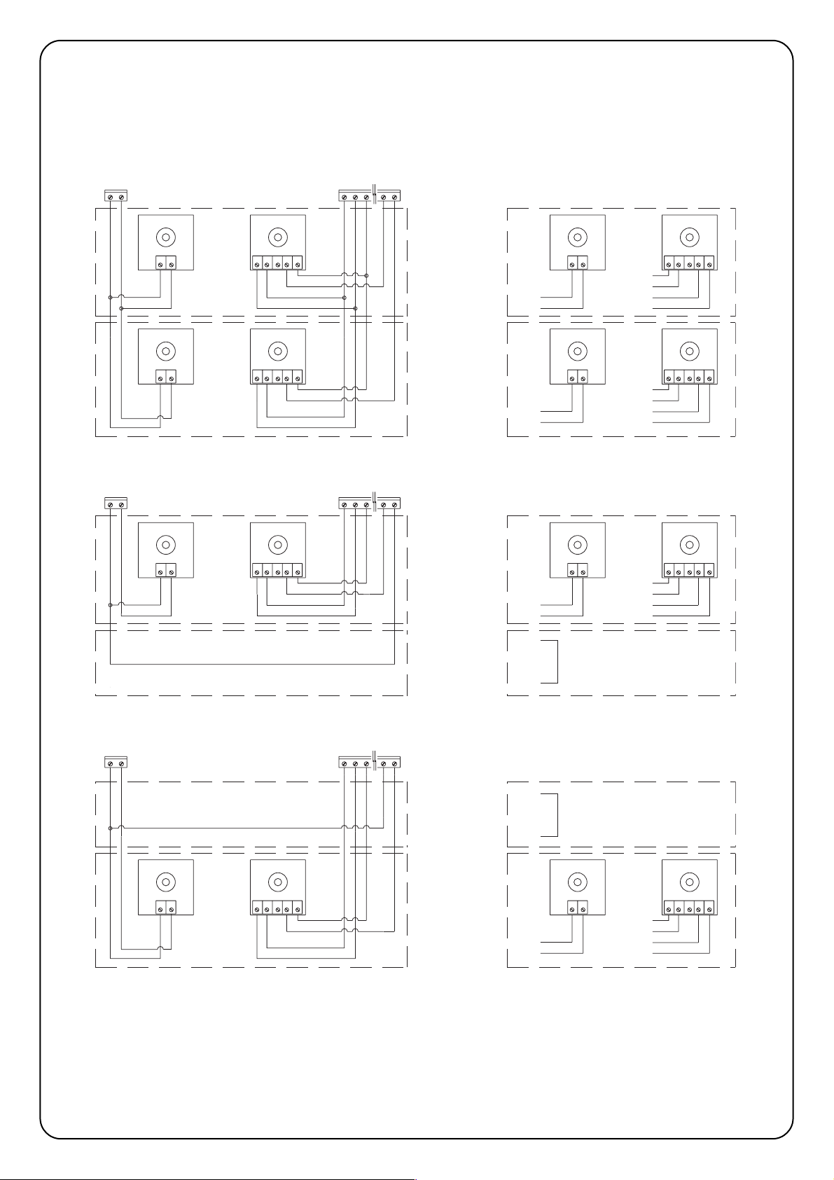
72
23
22
16
15
17
5423
RX
1
FOTO 2
TX
21
16
23
15
17
13
14
4231
RX
5
14
13
TX
21
FOTO 2
RX
54231
16
FOTO
TX
21
23
22
16
15
4231
RX
5
17
15
22
17
13
14
13
23
13
23
14
13
TX
21
FOTO
16
15
23
17
22
16
15
17
13
14
14
13
4231
RX
5
4231
RX
5
TX
21
TX
21
FOTO 2
FOTO
12 43251
5431221
17
22
23
16
15
RX
RXTX
TX
FOTO
FOTO 2
14
13
2.6) Fototest
La función Fototest es una solución ideal en términos de fiabilidad
para los dispositivos de seguridad y permite lograr, para el grupo de
la central y fotocélulas, la categoría 2, según la norma UNI EN 9541 (edic. 12/1998).
Para realizar esta solución, hay que conectar las fotocélulas como
muestran las figuras 3A, 3B o 3C, y colocar el Dip Switch 7 en On
(activación fototest).
Fig. 3A Conexión fototest con las fotocélulas "Fotocélula" y "Fotocélula 2"
Fig. 3B Conexión fototest con la fotocélula "Fotocélula" sola
Fig. 3C Conexión fototest con la fotocélula "Fotocélula 2" sola
Cuando se acciona un movimiento, en primer lugar se controla que
todos los receptores implicados en el movimiento den el asenso;
luego, se apaga la salida fototest y se controla que todos los receptores señalen el hecho cortando el asenso; por último, se reactiva la
salida fototest y se controla nuevamente el asenso por parte de
todos los receptores. Si durante esta secuencia se detecta que un
dispositivo no funciona, que un cable está en cortocircuito, etc., la
maniobra no se ejecuta.
Page 73

E
73
Una vez finalizadas las conexiones, es oportuno efectuar un control general, es decir:
• Alimente la central y compruebe inmediatamente que en los bornes 1-2 haya la tensión de red y que en los bornes 15-16 (salida equipos
auxiliares) haya una tensión de alrededor de 28 Vcc. Si los valores no corresponden, corte inmediatamente la alimentación y controle con
más atención las conexiones y la tensión de alimentación.
• Transcurridos alrededor de dos segundos del encendido, el led OK debe parpadear con una cadencia regular de un segundo, para
señalar el correcto funcionamiento de la central.
• Controle que los leds que corresponden a las entradas con contactos tipo normalmente cerrado (“Stop”, “Fotocélula” y “Fotocélula2”)
estén encendidos (dispositivos de seguridad accionados) mientras que los leds que corresponden a las entradas tipo Normalmente
Abierto estén apagados (ningún accionamiento activo); si esto no se produce, controle las conexiones y que todos los dispositivos
funcionen correctamente.
• Controle que todos los dispositivos de seguridad presentes en la instalación funcionen correctamente (parada de emergencia, fotocélulas,
bordes neumáticos, etc.); cada vez que se activan, se tienen que apagar los leds correspondientes Stop, Fotocélula o Fotocélula2.
• Controle si el movimiento se efectúa en la dirección correcta, es decir:
♦ desbloquee el motor y controle que el led de desbloqueo, situado en la tarjeta, esté encendido;
♦ coloque manualmente la puerta en una posición tal que se pueda abrir y cerrar libremente;
♦ bloquee de nuevo el motor y controle que el led de desbloqueo se haya apagado;
♦ oprima el botón “Cerrar” (ref. K de la Fig. 1) y controle que la puerta se cierre.
♦ Si la puerta se abre, oprima nuevamente el botón cerrar para detener el movimiento, corte la alimentación e invierta los dos cables
del motor.
♦ Independientemente del sentido del movimiento, es oportuno detener de inmediato la maniobra oprimiendo nuevamente el botón
“Cerrar”.
Si el control de las conexiones ha dado resultados positivos, se puede comenzar la etapa de búsqueda de los topes mecánicos.
La operación es necesaria porque la central A924 debe medir el espacio recorrido por el motor, en términos de números de impulsos
encoder, para colocar la puerta desde la posición de cierre máximo (cota 0) hasta aquella de apertura máxima (cota 1).
La cota 0 y la cota 1 sirven como referencia para las demás cotas indicadas en la representación gráfica de la Fig 4.
COTA 0: es el punto en donde la puerta seccional se encuentra en la situación de
cierre, que corresponde al tope mecánico (generalmente el piso).
COTA 1: es el punto en donde la puerta se encuentra en la situación de apertura
máxima, que corresponde a los topes mecánicos de apertura (punto M).
COTA A: es la posición en que se desea que la puerta se detenga en la maniobra de
apertura (no coincide necesariamente con los topes mecánicos de apertura).
COTA B: es la posición en que se desea que la puerta se detenga en la maniobra de
apertura parcial.
COTA RA: es la posición en que se desea que la puerta empiece a decelerar en la
maniobra de apertura normal.
COTA RC: es la posición en que se desea que la puerta empiece a decelerar en la
maniobra de cierre.
La búsqueda de los topes mecánicos se puede realizar por medio de la búsqueda inicial, la búsqueda automática o la programación manual.
Después de la "búsqueda inicial" o de la "búsqueda automática", si Ud. lo desea, puede modificar, a través de la programación manual, una
o varias cotas medidas en ciclo automático, excluidas la cota 0 y la cota 1 que son de referencia para las demás cotas.
3) PROGRAMACIÓN
2.7) Control de las conexiones
Las siguientes operaciones se efectúan con los
circuitos bajo tensión; algunas piezas están bajo tensión
de red, es decir, muy peligrosas.
Tenga mucho cuidado en lo que está haciendo y nunca
trabaje sólo.
!
1
A
RA
B
RC
0
M
Page 74

74
3.1)
Búsqueda inicial de los topes mecánicos
El proceso de "Búsqueda inicial de los topes mecánicos" se realiza automáticamente como primera maniobra después de la instalación.
Tabla “A” Para activar la búsqueda inicial de los topes mecánicos:
1. Desbloquee el motor y coloque manualmente la puerta en una posición tal que se pueda abrir y cerrar libremente; bloquee
el motor.
2. Oprima brevemente el botón “Abrir” (ref. I de Fig. 1) o Cerrar (ref. K de Fig. 1) situados en la tarjeta, o bien dé un impulso de
mando en las entradas y espere que la central ejecute un cierre lento hasta la cota 0, una apertura lenta hasta la cota 1 y
un cierre veloz hasta la cota 0.
Nota
. Si la primera maniobra después del mando es una apertura, accione otro mando para detener el procedimiento e
invertir la polaridad del motor.
3. Finalizada la secuencia antes descrita, con una operación matemática se calcula la cota A (apertura deseada) a pocos
centímetros de la apertura máxima, la cota B (apertura parcial) a alrededor de
3/4
de la cota A, y las cotas RA y RC
necesarias para las deceleraciones.
4. El procedimiento de “búsqueda inicial” de los topes mecánicos ha concluido y el motorreductor está listo para el uso.
Nota 1. Si durante la "Búsqueda inicial de los topes mecánicos" se acciona uno de los dispositivos de seguridad, o bien se da otro impul-
so de mando, el movimiento de la puerta se detendrá inmediatamente y habrá que repetir las operaciones antedichas.
3.2) Búsqueda automática de los topes mecánicos
Como alternativa a la "Búsqueda inicial", en cualquier momento es posible activar la "Búsqueda automática de los topes mecánicos". El procedimiento ejecuta automáticamente la búsqueda de los topes mecánicos (cota 0 y cota 1) con el mismo modo descrito en la “Búsqueda Inicial”.
Tabla “B” Para activar la búsqueda automática de los topes mecánicos:
1. Configure los Dip-Switches de la siguiente manera:
2. Desbloquee el motor y coloque manualmente la puerta de manera tal que se pueda abrir y cerrar libremente; bloquee de
nuevo el motor.
3. Oprima el botón “Cerrar” (ref. K de la Fig. 1) y espere que la central ejecute un cierre lento hasta la cota 0, una apertura lenta
hasta la cota 1 y un cierre rápido hasta la cota 0.
Nota. Si después del mando, la primera maniobra es una apertura, accione otro mando para detener el procedimiento e
invierta la polaridad del motor.
4. Del valor de dichas cotas, con una operación matemática, se calcula la cota A (apertura deseada) a pocos centímetros de
la apertura máxima, la cota B (apertura parcial) situada a
3/4
de la cota A y las cotas RA y RC necesarias para las
deceleraciones.
5. El procedimiento de "Búsqueda Automática" de los topes mecánicos ha concluido y el motorreductor está listo para el uso.
Nota1. Si durante la "Búsqueda Automática de los topes mecánicos" se acciona uno de los dispositivos de seguridad, o bien se da otro
impulso de mando, el movimiento de la puerta se detendrá inmediatamente y habrá que repetir las operaciones antedichas.
3.3) Procedimiento de memorización
En los próximos párrafos, al final de las secuencias de programación de algunos parámetros, se indicará "Procedimiento de memorización". Esta operación sirve para memorizar en la memoria permanente, que se encuentra en la central, el valor del parámetro que se
desea programar.
Tabla “C” Para ejecutar el procedimiento de memorización:
1. Oprima por 3 s como mínimo el botón “Memoria” (ref. J fig. 1); transcurridos 3 s el led “OK” (ref. R fig. 1) parpadea
rápidamente.
2. Suelte el botón “Memoria”; el led “OK” sigue parpadeando por otros 3 s.
3. Antes de tres segundos, oprima simultáneamente, y sólo por un instante, los dos botones “Abrir” y “Cerrar” (refs. I y K de
fig. 1); cuando se oprimen simultáneamente los dos botones, el led “OK” se apaga.
4. Suelte los dos botones “Abrir” y “Cerrar”; el led “OK” se enciende por alrededor de 2 s para confirmar que el procedimiento
de memorización del parámetro seleccionado se ha realizado correctamente.
12345678910 11 12
Page 75

E
75
3.4) Programación manual de los topes mecánicos
El procedimiento prevé la introducción manual de todas las cotas indicadas en la Fig 4, respetando el orden indicado en la tabla de abajo; en particular, la cota 0 es la cota de referencia; se debe programar primero y nunca se debe desplazar.
Tabla “D” Para programar manualmente las cotas:
1. Configure los Dip-Switches en uno de los modos indicados; según el parámetro que se ha de memorizar.
COTA 0: Tope mecánico de cierre
COTA RC: Posición en donde empieza la deceleración en la maniobra de cierre
COTA B: Posición de parada en la maniobra de Apertura parcial
COTA RA: Posición en donde empieza la deceleración en la maniobra de
apertura normal
COTA A: Posición de parada en la maniobra de Apertura normal
COTA 1: Tope mecánico de apertura
2. Oprima y mantenga apretado el botón “Abrir” (ref. I de Fig. 1) o “Cerrar” (ref. K de Fig. 1) en la tarjeta hasta alcanzar la cota
deseada.
Nota. Oprima el botón “Memoria” (ref. J de Fig. 1) si desea acelerar el movimiento.
3. Una vez alcanzada la cota, suelte los botones y ejecute el "Procedimiento de memorización" (párrafo 3.3).
Nota1. Como alternativa a la programación manual de todas las cotas, es posible memorizar sólo las cotas 0, A y 1 y obtener el movimiento
de la puerta con las cotas B, RA y RC calculadas automáticamente por la central.
3.5) Programación de la cota electrobloqueo
Cuando a la salida ELB se le asigna un funcionamiento tipo electrobloqueo (véase switch 8 en el párrafo 5) es posible programar el umbral,
que al ser superado, apaga la salida.
Tabla “E” Para programar la cota electrobloqueo:
1. Configure los Dip-Switches como indicado en la figura:
2. Oprima el botón “Abrir” (ref. I de Fig. 1) o “Cerrar” (ref. K de Fig. 1) hasta alcanzar la cota deseada.
Nota. Oprima el botón “Memoria” (ref. J de Fig. 1) si desea acelerar el movimiento.
3. Una vez alcanzada la cota, suelte los botones y ejecute el “Procedimiento de memorización” (párrafo 3.3)
12345678910 11 12
12345678910 11 12
12345678910 11 12
12345678910 11 12
12345678910 11 12
12345678910 11 12
12345678910 11 12
Page 76

76
3.6) Programación del tiempo pausa
Cuando se selecciona la función de cierre automático, tras una maniobra de apertura se activa un temporizador que controla el Tiempo
Pausa. Cuando concluye dicho tiempo, se activa automáticamente una maniobra de cierre. Este tiempo, si nunca ha sido programado, es
establecido por la central en 30 seg., pero con el procedimiento correspondiente, se puede programar cualquier valor comprendido entre
1 y 1023 seg. (alrededor de 17 minutos).
Tabla “F” Para programar el Tiempo Pausa:
1. Configure los Dip-Switches como indicado:
2.
Seleccione con el Dip-Switch de 10 vías el tiempo deseado, teniendo en cuenta que:
Ejemplo: tiempo pausa 25 s.
Dip 1 On activa la pausa por 1 s. 25 = 16+8+1
Dip 2 On " 2 " coloque en On los dips 5, 4 y 1
Dip 3 On " 4 "
Dip 4 On " 8 "
Dip 5 On " 16 "
Dip 6 On " 32 "
Dip 7 On " 64 "
Dip 8 On " 128 "
Dip 9 On " 256 "
Dip 10 On " 512 "
Colocando en On varios Dip Switches, el tiempo pausa seleccionado será igual a la suma de los tiempos pausa de cada
Dip-Switch;
3. Ejecute el “Procedimiento de memorización” (párrafo 3.3)
3.7 Cancelación de la memoria
Todos los parámetros programables se memorizan en una memoria tipo permanente que guarda las informaciones incluso cuando falta la
alimentación de red; podría ser necesario cancelar en bloque todo lo memorizado.
Tabla “G” Para cancelar el contenido de la memoria:
1. Configure los Dip-Switches como indicado
2. Ejecute el “Procedimiento de memorización” (véase párrafo 3.3) que en este caso sirve para confirmar la cancelación.
Nota. Con la memoria puesta a cero es como si el motorreductor no hubiera estado nunca instalado y, por consiguiente, no será posible
el movimiento normal de la puerta; en este caso, el primer mando que llegará a las entradas, o la presión de los botones “Abrir” o “Cerrar”,
activará inmediatamente un procedimiento de “Búsqueda inicial de los topes mecánicos”.
Nota 1. Con esta operación no se cancela el número de las maniobras ejecutadas ni el número de maniobras programadas.
3.8 Regulaciones
Finalizada la etapa de programación se pueden ejecutar las pocas
regulaciones indispensables para un funcionamiento correcto y
seguro de la automatización.
12345678910 11 12
12345678910 11 12
12345678910 11 12
Page 77

E
77
3.8.1) Regulación amperimétrica
Para limitar las fuerzas que se producen en el movimiento, requisito
impuesto por las normativas, la central tiene dos trimmers TR2 (ref.
C de Fig. 1) y TR1 (ref. D de Fig. 1) que permiten modificar el umbral
de accionamiento del sistema amperimétrico en la maniobra de
apertura y cierre respectivamente. Si durante el movimiento de la
puerta se detecta un obstáculo, se ejecuta una parada y, si está activo el funcionamiento “Semiautomático” o “Automático”, se pone en
marcha una maniobra en el sentido opuesto.
Si se acciona el sistema amperimétrico en la maniobra de cierre, la
central ejecuta una inversión y la maniobra de apertura, si no es
interrumpida, finaliza con la puerta contra el tope mecánico de apertura - cota 1 (reconfirmación de la posición).
Para aumentar aún más el nivel de seguridad, si el sistema amperimétrico se acciona tres veces consecutivas sin que la puerta logre
un cierre regular, se ejecuta una parada antecedida por una breve
inversión.
TR2 = Regulación amperimétrica de la maniobra de apertura.
TR1 = Regulación amperimétrica de la maniobra de cierre.
3.8.2) Regulación de la velocidad
Para limitar la energía cinética durante el impacto contra un obstáculo, además de la regulación del umbral de accionamiento del sistema
amperimétrico, se puede disminuir la velocidad de la puerta durante el funcionamiento normal.
La velocidad se puede regular de la siguiente manera:
• con el funcionamiento “Manual” sólo con el motor parado,
• con el funcionamiento “Semiautomático” o “Automático” con el motor parado, o durante el movimiento (excluidas las etapas de
aceleración o deceleración).
Tabla “H” Para regular la velocidad:
1. Oprima y mantenga apretado el botón “Memoria” (Ref. J de Fig. 1)
2. Después de un segundo…
♦ oprima y mantenga apretado el botón “Cerrar” (ref. K de Fig. 1) para disminuir la velocidad, o bien
♦ oprima y mantenga apretado el botón “Abrir” (ref. I de Fig. 1) para aumentar la velocidad.
3. Ni bien la velocidad haya llegado al valor deseado, suelte los botones (de esta manera la velocidad se memoriza
automáticamente)
Nota. El sistema de regulación es eficiente siempre que no se alcancen los valores límites mín. o máx. de las velocidades indicadas en el
manual de instrucciones del motor; si se alcanzan dichos límites, el led “OK” queda encendido siempre cuando se ha alcanzado el valor
máximo, y queda apagado siempre cuando se ha alcanzado el valor mínimo.
Page 78

78
El ensayo de la automatización tiene que ser efectuado por personal cualificado y experto que deberá establecer
los ensayos previstos de acuerdo con el riesgo presente.
El ensayo es la parte más importante de toda la etapa de realización de la automatización. Cada componente, tales como motor, dispositivo de parada de emergencia, fotocélulas, etc. pueden requerir un ensayo específico; por consiguiente, se aconseja seguir los procedimientos indicados en los manuales de instrucciones respectivos.
P
ara el ensayo de la central A924 ejecute el siguiente procedimiento:
1. Configure los Dip-Switches como indicado:
(todas las funciones desactivadas y funcionamiento semiautomático)
2. Oprima el botón “Abrir” (ref. I de Fig. 1) y controle que:
• se encienda la luz intermitente
• arranque una maniobra de apertura con la etapa de aceleración
• el movimiento se detenga, antecedido de la etapa de deceleración, cuando la puerta haya llegado a la cota A.
3. Oprima el botón “Cerrar” (ref. K de Fig. 1) y controle que:
• se encienda la luz intermitente
• arranque una maniobra de cierre
• el movimiento se detenga cuando la puerta haya llegado a la cota 0.
4. Haga arrancar una maniobra de apertura y controle que el accionamiento de un dispositivo conectado a la entrada
• “Stop”, provoque la parada inmediata del movimiento
• “Fotocélula”, no tenga ningún efecto
• “Fotocélula2”, provoque la parada y la inversión de la maniobra
5. Haga arrancar una maniobra de cierre y controle que el accionamiento de un dispositivo conectado a la entrada
• “Stop”, provoque la parada inmediata del movimiento
• “Fotocélula”, provoque la parada y la inversión de la maniobra
• “Fotocélula2”, no tenga ningún efecto
6. Accione un dispositivo conectado a la entrada:
• “Stop” y controle que, activando una entrada de mando, no arranque ninguna maniobra
• “Fotocélula” y controle que, activando una entrada de mando que provoca un cierre, no arranque la maniobra
• “Fotocélula2” y controle que, activando una entrada de mando que provoca una apertura, no arranque la maniobra
7. Tanto durante el movimiento de apertura como de cierre, impida el movimiento de la puerta con un obstáculo y controle que
la maniobra invierta el sentido antes de superar la fuerza prevista por las normativas.
8. Controle que la activación de las entradas (si están conectadas) provoque un paso en la secuencia
• para la entrada “Paso a Paso”: Abrir – Stop – Cerrar –Stop,
• para la entrada “Abrir”: Abrir – Stop – Abrir – Stop,
• para la entrada “Cerrar”: Cerrar - Stop- Cerrar – Stop,
• para la entrada “Abrir Parcial”: Abrir Parcial – Stop – Cerrar – Stop.
5) Funciones que se pueden seleccionar
Con los dip-switches programación en Off, el dip-switch funciones permite seleccionar las diferentes funciones, como indicado a continuación:
Switch 1-2 Off Off = Función “Manual” es decir Pulsador de interrupción automática
On Off = Función “Semiautomático”
Off On = Función “Automático” es decir Cierre Automático
On On = Función “Automático + Cerrar siempre”
Switch 3 On = Función comunitario <No disponible en modo Manual>
Switch 4 On = Prelampeggio 5 s.(2 s. se in manuale)
Switch 5 On = Cerrar 5 s después de Fotocélula si está en automático, o cerrar después de
Fotocélula si está en semiautomático
Switch 6 On = Fotocélula también durante apertura
Switch 7 On = Activación Fototest
Switch 8 On = Ventosa / Electrobloqueo (On = ventosa Off = electrobloqueo)
Switch 9 On = Semáforo en modo “dirección única”
Switch 10 On = Semáforo en “ambas direcciones”
Nota. Naturalmente, un Switch en "Off" no activa la función descrita.
4) Ensayo
!
12345678910 11 12
Page 79

E
79
5.1)Descripción de las funciones
Función Manual
El movimiento se efectúa sólo si se acciona el mando. El movimiento se detiene ni bien se suelta el mando después de un accionamiento de un dispositivo de seguridad (Stop, Fotocélula o Fotocélula2), o después de un accionamiento del sistema amperimétrico. Cuando el movimiento se ha detenido, es
necesario soltar el mando de entrada antes de poder iniciar un nuevo movimiento.
Función semiautomático y automático
En modo “Semiautomático” o “Automático”, luego de un impulso de mando, se ejecuta todo el movimiento hasta alcanzar la cota prevista. Un segundo
impulso sobre la misma entrada que ha comenzado el movimiento, provoca una parada. Si en una entrada de mando, en vez de un impulso, se mantiene
una señal continua, se provoca un estado de preponderancia en donde las demás entradas de mando quedan desactivadas (útil para conectar un reloj
en la apertura). Durante una maniobra, el accionamiento del sistema amperimétrico o de una fotocélula implicada en la dirección del movimiento (fotocélula en cierre, fotocélula2 en apertura) provoca la inversión.
En el modo de funcionamiento Automático, después de una apertura, se ejecuta una pausa y luego un cierre.
Si durante la pausa se acciona Fotocélula, el temporizador se restablecerá con un tiempo nuevo; si en cambio, durante la pausa se acciona la entrada
Stop, la función de cierre se cancelará y se pasará a un estado de Stop.
Función “Cerrar Siempre”
Pone en marcha automáticamente una maniobra de cierre, antecedida por 5 segundos de parpadeo previo, si al restablecimiento de la alimentación, se
detecta que la puerta está abierta.
Función Comunitario
Durante el funcionamiento comunitario, una maniobra de apertura no se puede interrumpir por impulsos de mando, salvo aquellos que provocan un cierre.
Durante el movimiento de cierre, un impulso de mando nuevo provoca la parada e inversión del movimiento en apertura.
Parpadeo previo
Al recibir el impulso de mando, primero se activa la luz intermitente, luego, transcurridos 5 segundos (2 seg. si está en modo manual) inicia el movimiento.
Cerrar 5 s después de Fotocélula si está en automático, o Cerrar después de Fotocélula si está en semiautomático
En modo automático, un accionamiento de fotocélula en la maniobra de apertura o cierre disminuye el tiempo de pausa a 5 s independientemente del tiempo de pausa programado. En modo semiautomático, un accionamiento de fotocélula en la maniobra de cierre activa el cierre automático con el tiempo de
pausa programado.
Fotocélula también durante apertura
Con esta función, el accionamiento del dispositivo de seguridad Fotocélula interrumpe el movimiento, incluso de apertura, si está seleccionada la función
“Semiautomático” o “Automático”; inmediatamente después de la desactivación de la Fotocélula, se reanudará el movimiento de apertura.
Activación Fototest
Esta función permite ejecutar al inicio de cada maniobra un control de todas las fotocélulas, aumentando así la seguridad de la instalación. Para mayores
detalles, consulte el párrafo 2.6 Fototest
Ventosa/electrobloqueo
La función permite asignar a la salida ELB (bornes 11 y 12) un funcionamiento tipo:
• electrobloqueo (Switch 8 Off) - la salida se activa en la maniobra de apertura con la puerta cerrada y queda activa hasta que la puerta no haya
superado la cota electrobloqueo (programable, véase párrafo 3.5);
• ventosa (Switch 8 On) - la salida se activa al final del movimiento de cierre y queda activa por todo el tiempo en que la puerta está cerrada.
Semáforo en modo “dirección única”
En este modo la salida “SCA” está activa con la puerta abierta y, durante la maniobra de apertura, queda encendida; mientras que se desactiva en la maniobra de cierre y con la puerta cerrada. En este modo a la salida se le puede aplicar una lámpara verde que, al encenderse, indica paso libre.
Semáforo en ambas direcciones
Colocando el switch 10 en On, independientemente del switch 9, se activa la función “semáforo en ambas direcciones”; en la central se producen los siguientes
cambios: la entrada Abrir se vuelve Paso a Paso2; mientras que las dos salidas Luz de cortesía (“COR”) e Indicador luminoso Cancela Abierta (“SCA”) se vuelven
Luz Verde para una dirección y Luz Verde para la otra, como indicado en la Fig. 5. Para cada dirección de marcha se coloca un mando diferente para la apertura: Paso a Paso (PP) para entrar y Paso a Paso2 (PP2) para salir; se instalan dos semáforos con señales Roja y Verde conectadas a las salidas “SCA” y “COR”.
Normalmente, las dos salidas SCA y COR están apagadas y, de consecuencia, también lo están los semáforos; cuando se da un mando con PP para
entrar, se pone en marcha una maniobra de apertura y, simultáneamente, se activa el SCA que enciende la luz verde de entrada y la luz roja de salida. En
cambio, si el mando para la apertura es dado por PP2, se activa la salida COR que activa la luz verde de salida y la luz roja de entrada. La luz quedará
encendida durante la etapa de apertura y durante la posible etapa de pausa; en cambio, en la etapa de cierre se activarán simultáneamente las luces
verdes y rojas, indicando que no hay prioridad para pasar.
Las dos salidas pueden accionar directamente pequeñas bombillas de 24Vcc por un total máximo por salida de 10W. Si fuera necesario usar bombillas
de mayor potencia, será oportuno usar relés controlados por las salidas de la central, que a su vez accionen las lámparas del semáforo.
Page 80

80
6) Mantenimiento
La tarjeta como pieza electrónica no requiere ningún tipo de mantenimiento especial. De todas maneras, controle periódicamente (cada 6 meses
como mínimo) el funcionamiento correcto de la tarjeta y de los dispositivos conectados, ejecutando nuevamente el ensayo (véase el Cap. 4).
Para planificar los trabajos de mantenimiento de toda la instalación, en la central hay un contador de maniobras que aumenta su valor en cada
movimiento de apertura. El aumento está señalado por un parpadeo del indicador luminoso mantenimiento (MAN). El valor del contador de maniobras se compara constantemente con un umbral de alarma (programable por el instalador) y con el umbral de seguridad (que se configura
automáticamente igual al umbral de alarma menos el 6% aprox.). Cuando el número de las maniobras ejecutadas supera el umbral de seguridad,
el indicador mantenimiento parpadea sólo durante la maniobra, mientras que si se supera el umbral de alarma, parpadea continuamente (con el
motor detenido y durante el movimiento) indicando que es necesario hacer el mantenimiento.
El umbral de alarma se puede programar desde un valor mínimo de 200 hasta un valor máximo de 50800 maniobras en múltiplos de 200.
Tabla “I” Para configurar el umbral de alarma
1. Configure los Dip-Switches como indicado
2. Divida el número de las maniobras a programar por 100 y por 2 Ejemplo: número de maniobras
3. Localice en la tabla la combinación de dip switch cuya suma de los valores es a programar 30000
igual al número del resultado y coloque los Dip Switches correspondientes en On. Resulta después de la división: 150
150 = 128 + 16 + 4 + 2,
Dip Switch 8, 5, 3 y 2 en On
4. Ejecute el “Procedimiento de memorización” (véase párrafo 3.3).
Tras haber programado el umbral de alarma, es posible visualizarlo para estar seguro de que la operación se ha efectuado correctamente.
Tabla “L” Para visualizar el umbral de alarma:
1. Configure los dip switches como indicado:
2. Coloque el Dip Switch 1 en On (2, 3, 4 y 5 en Off), cuente el número de parpadeos del led “OK” y escriba el número de
parpadeos en una hoja de papel (si es 10, escriba 0)
3. Repita la operación con los Dip Switches 2, 3, 4 y 5
4. Reconstruya el número de las maniobras, como indicado en uno de los dos siguientes ejemplos
Con el mismo procedimiento también se puede visualizar el número de maniobras efectuadas.
Tabla “M” Para visualizar el número de maniobras efectuadas:
1. Configure los Dip Switches como indicado:
2. Repita la cuenta de parpadeos del led “OK” con los Dip Switches 1, 2, 3, 4, 5 como indicado en el ejemplo 1 ó 2.
Nota. Cada vez que se programa el umbral de seguridad, se cancela automáticamente el número de maniobras ejecutadas.
Dip-switch Sw1 Sw2 Sw3 Sw4 Sw5 Sw6 Sw7 Sw8
Valor 1248163264128
Configuración
Dip switch
Número
Maniobras
Ejemplo
n° 1
Número de parpadeos
Led “OK”
10
1
1
4
2
10
10
10
4
7
1.204
Ejemplo
n° 2
Número de parpadeos
Led “OK”
14.007
12345678910 11 12
12345678910 11 12
12345678910 11 12
123456
123456
123456 123456 123456
12345678910 11 12
Page 81

E
81
6.1) Desguace
Este producto está formado de varios tipos de materiales; algunos
de tales materiales se pueden reciclar. Infórmese sobre los métodos
de reciclaje o desguace ateniéndose a las normas locales vigentes.
Algunos componentes electrónicos podrían contener
sustancias contaminantes: no los abandone en el medio
ambiente.
La central tiene un conector para conectar un radiorreceptor
(opcional) que permite actuar sobre la entrada Paso a Paso y así
accionar a distancia la central por medio de un transmisor. El posible contacto sin tensión del segundo canal está disponible en los
bornes 41-42.
Antes de conectar el receptor, corte la alimentación eléctrica y posibles baterías y conecte el receptor con los componentes dirigidos
hacia el microprocesador de la central.
La central tiene un transformador de potencia adecuada para soportar la energía requerida por el motor y por la tarjeta electrónica cuando
todo está alimentado directamente desde la red de alimentación. Si desea que la automatización funcione igualmente cuando falta la energía
eléctrica, es suficiente conectar baterías adecuadas. La central carga las baterías cuando hay corriente eléctrica, mientras que cuando falta la energía de red, se conmuta automáticamente de manera que las baterías sean las que suministren la energía necesaria para el funcionamiento.
Tabla “N” Para conectar las baterías
1. Antes de conectar las baterías, instale la automatización y asegúrese de que todo funcione correctamente.
2. Controle que el led batería esté encendido y que la tensión en los bornes sea de alrededor de 27 voltios.
Tenga mucho cuidado con la siguiente operación, porque está trabajando con circuitos bajo tensión.
3. Conecte las baterías como indicado en la Fig. 6
4. Inmediatamente después de haber conectado las baterías a la central, controle que el led batería esté todavía encendido; si
estuviera apagado, desconecte inmediatamente las baterías y controle la polaridad de la conexión.
5. Si el led batería está encendido, controle nuevamente la tensión en los bornes de la batería; si la tensión:
• es inferior a 18 Vcc, las baterías no están conectadas correctamente o están averiadas.
• está comprendida entre 18 y 25Vcc, las baterías están agotadas; conviene esperar que se carguen.
• es superior a 25 Vcc, las baterías están cargadas, corte la alimentación de red y controle que la automatización siga
funcionando regularmente; entonces, conecte nuevamente la alimentación de red.
Nota. Con el funcionamiento con batería, el motor tiene una velocidad inferior respecto del funcionamiento de la central alimentada con la
red eléctrica.
Nota 1. Si ambos sistemas de alimentación están presentes (red eléctrica y batería) y se desea desconectar la central para el
mantenimiento, o por razones de seguridad, hay que desconectar la alimentación eléctrica, desconectar las baterías o quitar el fusible
batería F4 que está en la central.
7) Funcionamiento con baterías
8) Radiorreceptor
!
!
Page 82

82
A continuación indicamos algunos de los problemas más comunes que se le pueden presentar durante la instalación.
• No hay ningún led encendido:
controle que en los bornes 1 y 2 haya tensión de red y que los fusibles F1 o F3 no estén quemados.
• La maniobra no arranca:
controle que los leds de los dispositivos de seguridad “Stop”, “Fotocélula” y “Fotocélula2” estén encendidos y que el motor esté bloqueado (led desbloqueo apagado).
• Durante la maniobra se ejecuta una inversión:
Controle que no se haya accionado ningún dispositivo de seguridad (fotocélula de cierre y fotocélula2 de apertura) o que no se haya
accionado el sistema amperimétrico; en este último caso, controle que la regulación efectuada sea suficiente para el movimiento de la
puerta. Si así no fuera, aumente el nivel girando hacia la derecha uno de los dos trimmers (TR2 para la apertura, TR1 para el cierre).
• El Led “OK” parpadea rápidamente:
la tensión de alimentación no es suficiente o con los Dip Switches se ha seleccionado una combinación incorrecta.
• El motor se mueve lentamente:
si había sido desbloqueado antes, la central está realizando una operación de alineación; el primer accionamiento del sistema amperimétrico es considerado como tope mecánico y la posición correcta es restablecida por la memoria.
• El motor ejecuta la etapa de aceleración y se detiene:
controle si el Led encoder parpadea durante el movimiento del motor. La frecuencia del parpadeo puede ser más o menos alta, según
la velocidad del movimiento. Con el motor detenido, el led puede estar encendido o apagado según el punto en donde se ha detenido
el eje motor.
• Led “OK” fijo por algunos segundos inmediatamente después de un mando:
indica que hay una irregularidad en la etapa de mando del motor; controle los cables y el aislamiento hacia tierra del motor; si fueran
correctos, sustituya la central.
9) Que hay que hacer si…
Alimentación : Central A924 ➡ 230 Vca ± 10 %, 50-60Hz
: Central A924/V1 ➡ 120 Vca ± 10 %, 50-60Hz
Alimentación con batería : 21 ÷ 28 Vcc (2 baterías de 12 voltios, capacidad 6Ah)
Regulación amperimétrica : desde 2,5 hasta 15 A
Salida equipos auxiliares : 24 Vcc, corriente máxima 200mA
Salida fototest : 24 Vcc corriente máxima 200 mA
Salida luz intermitente : 24 Vcc, potencia máxima 25 W
Salida electrobloqueo : 24 Vcc, corriente máxima 500 mA
Salida Indicador SCA : 24 Vcc potencia máxima 5W
Salida luz de cortesía : 24 Vcc potencia máxima 5W
Salida Indicador mantenimiento : 24 Vcc potencia máxima 2 W
Tiempo Pausa : programable desde 1 hasta 1023 segundos
Tensión de carga de las baterías : 27 Vcc
Corriente de carga : 200 mA
Tiempo recarga completa : 24 h aprox. para dos baterías de 12V - 6Ah
Temperatura de servicio : - 20 a + 70 °C
Grado de protección : IP55
Medidas y peso : 220 X 280 h 110, alrededor de 4 kg
10) Características técnicas
Page 83

83
Nice se reserva el derecho de modificar los productos en cualquier momento en que lo considerará oportuno.
Page 84

84
mindy A924
Ostrzeżenie:
Niniejsza instrukcja przeznaczona jest jedynie dla personelu
technicznego z odpowiednimi kwalifikacjami do instalowania.
řadna informacja znajdująca się w niniejszej instrukcji nie jest
skierowana do końcowego użytkownika! Instrukcja ta odnosi się
do centrali A924 i nie może być zastosowana do innych
produktów. Centrala A924 jest przeznaczona do zarządzania
aktuatora elektromechanicznego SUMO, wykonanego przez
firmę Nice S.p.A. i każde inne zastosowanie będzie uważane za
niewłaściwe, co jest też zabronione aktualnymi normami. Przed
przystąpieniem do instalowania zalecamy, aby przeczytać całą
instrukcję.
Spis : pag.
1 Opis produktu 85
2 Instalowanie 85
2.1 Kontrola wstępna 85
2.2 Mocowanie centrali A924 85
2.3 Połączenia elektryczne 86
2.4 Schemat elektryczny 86
2.5 Opis połączeń 87
2.6 Fototest 88
2.7 Kontrola połączeń 89
3 Programowanie 89
3.1 Wstępne poszukiwanie zatrzymań mechanicznych 90
3.2
Automatyczne poszukiwanie zatrzymać mechanicznych
90
3.3 Procedura zachowywania 90
3.4 Ręczne programowanie zatrzymań mechanicznych 91
3.5 Programowanie wartości elektroblokady 91
3.6 Programowanie czasu przerwy 92
3.7 Kasowanie pamięci 92
3.8 Regulacje 92
3.8.1 Regulacja amperometryki errore 93
3.8.2 Regulacja prędkości 93
4 Próby ostateczne 94
5 Funkcje z możliwością wyboru 94
5.1 Opis funkcji 95
6 Czynności konserwacyjne 96
6.1 Zbyt 97
7 Funkcjonowanie na baterie 97
8 Odbiornik radiowy 97
9 Co robić gdy... 98
10 Dane techniczne 98
!
Page 85

PL
85
Funkcjonowanie centrali A924 opiera się na systemie kontroli
pozycji pracy, którą wykonuje czujnik magnetyczny (enkoder)
zamontowany wewnątrz silnika. Technika ta służy do
odczytywania stopnia obrotu wału i umożliwia wykonanie kontroli
funkcji ustawiania i regulacji prędkości. Ze względu na funkcję
kontroli prędkości i momentów silnika, centrala potrafi odczytać
obecność przeszkody (“funkcja amperometryczna“). Centrala
wyposażona jest w licznik ruchów, który służy do planowania prac
związanych z czynnościami konserwacyjnymi, jest
przystosowana do założenia odbiorników radiowych
wyprodukowanych przez firmę Nice, posiada także wewnętrzne
urządzenia do ładowania baterii.
Na fig. 1 przedstawiony jest całkowity widok karty ze wskazaniem
podstawowych elementów.
2.1) Kontrola wstępna
Przypominamy, że urządzenia do bram i drzwi
automatycznych mogą być zainstalowane tylko przez
personel z odpowiednimi kwalifikacjami i zgodnie z
obowiązującymi normami.
Przed przystąpieniem do instalowania:
• Kierować się wskazówkami zawartymi w instrukcji “Uwagi dla
instalatora”.
• Sprawdzić, czy zatrzymania mechaniczne są w stanie
zatrzymać ruch bramy i czy bez problemów wchłoną całą
energię kinetyczną zebraną w ruchu.
A
B
C
D
E
F
G
H
I
J
K
L
M
N
O
P
Q
R
S
T
U
V
W
X
Y
Z
Łącze drugorzędnego transformatora 1
Bezpiecznik topikowy silnika (F2)
Regulacja amperometrycznej otwierania
Regulacja amperometrycznej zamykania
Bezpiecznik topikowy lampy sygnalizacyjnej, elektroblokada,
Fotokomórki, funkcje (F3)
Łącze drugorzędne transformatora 2
Mikroprocesor
Gniazdo na odbiornik radiowy
Przycisk: “otwiera“
Przycisk: “pamięci“
Przycisk: “zamyka“
Zacisk anteny i drugiego kanału radiowego
Dip Switch programowania
Dip Switch funkcji
Łącze do napędu bramy
Dioda wejść
Zaciski: silnik, wejścia, wyjścia
Dioda “OK“
Dioda odblokady
Dioda enkoder
Bezpiecznik topikowy baterii (F4)
Zaciski do połączenia linii zasilania
Bezpiecznik topikowy linii (F1)
Łącze pierwszorzędne transformatora
Dioda bateria
Zacisk baterii
ABCD
2) Instalowanie
2.2) Mocowanie centrali A924
Centrala dostarczona jest w skrzynce, która gdy zostanie odpowiednio
zainstalowana, gwarantuje stopień zabezpieczenia z klasyfikacją IP55,
z tego też powodu można ją zamontować na zewnątrz.
Jak przymocować centralę:
• Centralę przymocować do powierzchni gładkiej, nieruchomej i
ochronionej przed przypadkowymi uderzeniami. Część dolna
centrali ma znajdować się na wysokości nie niższej niż 40 cm
od ziemi.
• Założyć odpowiednie przewody rurowe na przewody i instalacje
tylko w dolnej części centrali. W żadnym wypadku nie
wykonywać otworów w ściankach górnych i bocznych.
Przewody mogą wychodzić tylko przez ściankę dolną!
• Wsunąć do odpowiednich otworów górnych dwie śruby (fig 2A)
i częściowo przykręcić. Centralę przekręcić o 180Ą, wykonać te
same czynności z dwoma pozostałymi śrubami (fig 2B).
Przymocować centralę do ściany.
• Założyć pokrywę (otwieranie drzwiczek prawe lub lewe) i
przycisnąć mocno po stronie strzałek (fig 2C).
• Aby ściągnąć pokrywkę, podważyć ją śrubokrętem w punkcie
gdzie jest osadzona, i jednocześnie pchnąć w kierunku do góry
(fig 2D).
1) Opis produktu
ABCDE FG
Z
Y
X
PQSRTQUVW
H
I
J
K
L
M
N
O
!
Page 86

86
2.3) Połączenia elektryczne
Mając na uwadze bezpieczeństwo instalatora oraz aby
uniknąć uszkodzenia elementów to, podczas wykonywania
połączeń elektrycznych czy zakładania odbiornika radiowego,
centrala musi być całkowicie odłączona od sieci i/lub baterii.
Podczas wykonywania połączeń należy kierować się schematem elektrycznym (paragraf 2.4), mając na uwadze że:
•
Podłączenie zasilania do centrali wykonać przewodem 3 x 1,5
mm
2
(faza, neutralny i uziemienie). Gdy jednak odległość
pomiędzy centralą i uziemieniem jest dłuższa od 30 m., wówczas
należy wykonać dodatkowe uziemienie w pobliżu centrali
• Połączenie SUMO z silnikiem wykonać przewodem 3x2,5 mm
2
(przy ponad 10m zastosować 4 mm2), połączenie do enkodera
przewodem 2 x 0,75 mm
2
•
Do połączenia lampy sygnalizacyjnej z elektroblokadą polecamy
zastosowania przewodu o przekroju minimalnym 1 mm
2
• Do połączeń części z niskim napięciem bezpieczeństwa należy
stosować przewody z przekrojem minimalnym 0,25 mm2 (gdy
odległość przekracza 30 m należy zastosować przewody
opancerzone, oplot uziemienia po stronie centrali)
• Zwrócić uwagę na połączenia urządzeń z zaznaczoną
biegunowością (lampa sygnalizacyjna, elektroblokada, wyjście
fototestu, funkcje, bateria, itp.)
• Wejścia typu Zwykle Zamknięty (NC), gdy nie są używane,
należy je połączyć, mostkiem, ze “Wspólnym 24 Vps“; wejścia
typu Zwykle Otwarte (NA), gdy nie są używane, należy je
pozostawić wolne.
• Kontakty mają być typu mechanicznego, bez napięcia; nie są
dozwolone połączenia typu określonego jak: “PNP“, “NPN“ ,
“Open Collector“ itp.
2.4) Schemat elektryczny
!
Page 87

PL
87
2.5) Opis połączeń
Zaciski Funkcje Opis
1-2 Faza - Neutralny = Zasilanie z sieci
3 Uziemienie = Podłączenie uziemienia do centrali
4 Uziemienie = Uziemienie silnika
5-6 Silnik = Zasilanie silnika 36 Vps
7-8 Enkoder = Wejście Enkodera silnika
Lampa Sygnalizacyjna = Wyjście lampy sygnalizacyjnej 24 Vps max 25W
11-12 Elektroblokada/ Przyssawka = Wyjście elektroblokady/ przyssawka 24Vps max 500 mA
13-14 Fototest = Wyjście fototestu
15-16 24 Vpp = Zasilanie funkcji 24 Vps maksymalnie 200mA
17 Wspólny = Wspólny dla wszystkich wejść
18 Sca = Wyjścia Lampy sygnalizacyjnej otwartej bramy (zapala się gdy brama się otwiera i
gaśnie gdy brama jest zamknięta, świeci się z szybkimi przerwami podczas fazy
zamykania)
19 Cor = Wyjście światełka „grzecznościowego„ (zapala się na początku ruchu i świeci się
tylko przez następne 60 sekund),
20 Man = Wyjście lampy ostrzegawczej czynności konserwacyjnych
21 Alt = Wejście z funkcją ALT (Alarm, blokada lub zabezpieczenie zewnętrzne).
22: Foto = Wejście urządzeń bezpieczeństwa (Fotokomórki, brzegi pneumatyczne) zainterwe
niują ruchu zamykania
23: Foto 2 = Wejście urządzenia bezpieczeństwa (Fotokomórki, brzegi pneumatyczne) z przerwą
w ruchu podczas otwierania
24: Skok po skoku = Wejście funkcji cyklicznej Otwiera Stop Zamyka Stop
25 Otwiera = Wejście fazy otwierania cyklicznego Otwiera Stop Otwiera Stop
26 Zamyka = Wejście fazy zamykania cyklicznego Zamyka - Stop- Zamyka -Stop
27 Otwiera częściowo = Wejście funkcji cyklicznej Otwiera Częściowo - Stop Zamyka - Stop
41-42 2° Ch Radio = Wyjście drugiego kanału odbiornika radiowego
43-44 Antena = Wejście Anteny odbiornika radiowego
+ - Bateria = Połączenie Baterii 24 volt
Page 88

88
23
22
16
15
17
5423
RX
1
FOTO 2
TX
21
16
23
15
17
13
14
4231
RX
5
14
13
TX
21
FOTO 2
RX
54231
16
FOTO
TX
21
23
22
16
15
4231
RX
5
17
15
22
17
13
14
13
23
13
23
14
13
TX
21
FOTO
16
15
23
17
22
16
15
17
13
14
14
13
4231
RX
5
4231
RX
5
TX
21
TX
21
FOTO 2
FOTO
12 43251
5431221
17
22
23
16
15
RX
RXTX
TX
FOTO
FOTO 2
14
13
2.6) Fototest
Funkcja Fototestu jest optymalnym rozwiązaniem w zakresie
urządzeń bezpieczeństwa i pozwala na osiągnięcie drugiej
kategorii bezpieczeństwa, według normy UNI EN 954-1 (wyd.
12/1998) w zakresie central i fotokomórek. Aby wykorzystać to
rozwiązanie, należy podłączyć fotokomórki tak jak wskazano na
jednej z figur: 3A, 3B o 3C, i ustawić Dip-Switch 7 na On
(uaktywnienie fototestu).
Fig 3A Podłączenie fototestu z fotokomórkami Foto e Foto2
Fig 3B Podłączenie fototestu z tylko jedną fotokomórką Foto
Fig 3C Podłączenie fototestu z tylko jedną fotokomórką Foto2
Przed wykonaniem żądanego ruchu zostanie wykonana kontrola,
czy wszystkie określone odbiorniki dadzą zezwolenie na
wykonanie ruchu. Następnie zostanie wyłączone wyjście
fototestu w celu sprawdzenia zasygnalizowania tego przez
odbiorniki po odebraniu tego zezwolenia. Na koniec zostanie
ponownie włączone wyjście fototestu i ponownie zostanie
sprawdzone czy wydane zostanie zezwolenie ze wszystkich
odbiorników. Gdy podczas wykonywania powyższej sekwencji
jedno z urządzeń nie będzie działało lub zaistnieje spięcie na
przewodach, itp., to ruch nie zostanie wykonany.
Page 89

PL
89
Po wykonaniu połączeń należy wykonać ogólną kontrolę:
• Podłączyć zasilanie do centrali i sprawdzić czy na zaciskach 1-2 jest obecne napięcie sieci i czy na zaciskach 15-16 (Wyjście funkcji)
jest obecne napięcie około 28 Vps . Gdy wartości te nie są zgodne należy natychmiast wyłączyć zasilanie i sprawdzić dokładnie
połączenia i napięcie zasilania.
• Po dwóch sekundach po włączeniu dioda OK będzie się świecić w sposób przerywany, z przerwami co 1 sekundę. Oznaczać to
będzie bezbłędne działanie centrali.
• Sprawdzić czy świecą się odpowiednie diody /zabezpieczenia aktywne poszczególnych wejść z kontaktami zwykle zamkniętymi (Alt,
Foto i Foto 2) i czy diody poszczególnych wejść zwykle otwartych są zgaszone (brak funkcji). Gdy tak nie jest należy sprawdzić
połączenia i funkcjonowanie poszczególnych urządzeń.
• Sprawdzić funkcjonowanie wszystkich zabezpieczeń występujących w urządzeniu (zatrzymanie w alarmie, fotokomórki, brzegi
pneumatyczne, itp.) i gdy te zabezpieczenia zainterweniują, powinny zgasić się odpowiednie diody: Alt, Foto lub Foto 1..
• Sprawdzić prawidłowość kierunku obrotu silnika;
• Odblokować silnik i sprawdzić czy dioda odblokady na karcie się zaświeci;
♦ Ręcznie ustawić bramę, tak aby się swobodnie otwierać i zamykać;
♦ Zablokować ponownie silnik i sprawdzić czy dioda zgasła;
♦ Przycisnąć przycisk Zamyka (odp. K na Fig.1) i sprawdzić czy brama się zamyka;
♦ Gdy wykonywany ruch jest ruchem otwierania wówczas należy ponownie przycisnąć przycisk Zamyka aby zatrzymać ruch,
odłączyć zasilanie i zmienić podłączenie przewodów do silnika;
♦ Niezależnie od kierunku ruchu należy zatrzymać natychmiast ruch przez ponowne przyciśnięcie przycisku Zamyka
Gdy wykonana kontrola połączeń da wynik pozytywny, można zacząć fazę poszukiwania zatrzymań mechanicznych.
Jest to czynność niezbędna, ponieważ centrala A924 musi zmierzyć przestrzeń przebiegu silnika, w zakresie impulsów enkodera, tak
aby doprowadzić bramę do maksymalnej pozycji zamknięcia (wartość 0) i do maksymalnej pozycji otwarcia (wartość 1).
Wartość 0 i wartość 1 służą jak wzorzec dla wszystkich wartości wskazanych na przedstawieniu graficznym na fig. 4
WARTOŚĆ 0: jest punktem, w którym brama sekcyjna jest w fazie zamykania,
odpowiadającym zatrzymaniu mechanicznemu (zwykle jest to podłoże).
WARTOŚĆ 1: jest punktem, w którym brama znajduje się w maksymalnej fazie
otwierania, odpowiadającym zatrzymaniu mechanicznemu otwierania (punkt M)
WARTOŚĆ A: jest punktem gdzie jest wymagane aby brama zatrzymała się w ruchu
otwierania (nie koniecznie odpowiadająca zatrzymaniu mechanicznemu w otwieraniu ).
WARTOŚĆ B: jest punktem gdzie jest wymagane aby brama zatrzymała się w ruchu
częściowego otwarcia .
WARTOŚĆ RA: jest punktem gdzie jest wymagane aby brama zaczęła zwalniać w ruchu
otwierania normalnego.
WARTOŚĆ RC: jest punktem gdzie jest wymagane aby brama zaczęła zwalniać podczas
zamykania .
Poszukiwanie zatrzymania mechanicznego może odbyć się poprzez wstępna fazę poszukiwania, poszukiwanie automatyczne lub
poprzez system ręcznego programowania. Po wykonaniu “wstępnego poszukiwania” lub “poszukiwania automatycznego”, można
zmienić jedną lub więcej wartości systemem ręcznego programowania; wartość 0 i wartość 1 nie można zmienić bo są one
wartościami wzorcowymi dla wszystkich wartości.
3) PROGRAMOWANIE
2.7) Kontrola połączeń
Dalsze czynności będą wykonane na obwodach pod
napięciem. Niektóre z nich są bardzo niebezpieczne, gdyż
będą pod napięciem sieciowym!
Wszystkie czynności należy wykonywać z maksymalną
ostrożnością i nigdy nie wolno pracować samodzielnie!
!
1
A
RA
B
RC
0
M
Page 90

90
3.1)
Wstępne poszukiwanie zatrzymań mechanicznych
Procedura “Poszukiwanie wstępne zatrzymań mechanicznych” jest wykonana automatycznie jako pierwsza czynność po zainstalowaniu.
Tabela “A” Aby uaktywnić wstępne poszukiwanie zatrzymań mechanicznych należy:
1. Odblokować silnik i ręcznie ustawić bramę, tak aby była swobodna w ruchu zamykania i otwierania, zablokować silnik.
2. Szybko przycisnąć przycisk, Otwiera (odp. I na Fig 1) lub Zamyka (odp. K na Fig 1), obecny na karcie lub wywołać
impuls zarządzania na wejściach i odczekać do chwili aż centrala wykona wolne zamykanie do pozycji wartości 0,
jedno wolne otwieranie do wartości 1 i jedno zamykanie szybkie aż do wartości 0.
Uwaga. Gdy wydaniu polecenia pierwszego ruchu będzie to otwieranie to należy zatrzymać procedurę i zmienić
biegunowość silnika.
3. Po zakończeniu powyższej sekwencji zostanie obliczona wartość A (żądanego otwierania) kilka centymetrów od
maksymalnego otwarcia, wartość B (otwarcie częściowe) na około 3/4 wartości A, wartości RA i RC niezb
ę
dne do fazy
zwolnienia.
4. Ustawić Dip Switch
"funkcje" wed
ług życzenia.
Procedura "wstępnego poszukiwania zatrzymań mechanicznych" jest
zakończona i motoreduktor jest ju
ż
gotowy do użytku.
Uwaga 1. Gdy w trakcie fazy “wstępnego poszukiwania zatrzymań mechanicznych”zainterweniowało jedno z zabezpieczeń lub
odebrany został inny impuls zarządzający to ruch bramy zostanie natychmiast zatrzymany, będzie więc niezbędne powtórzenie
czynności wyżej opisanych.
3.2) Automatyczne poszukiwanie zatrzymań mechanicznych
Alternatywą procedury “wstępnego poszukiwania“jest możliwość uaktywnienia, w jakimkolwiek momencie procedury “automatyczne
poszukiwanie zatrzymań mechanicznych
“
. Procedura ta automatycznie poszukuje zatrzymania mechaniczne (wartość 0 i wartość 1)
tym samym sposobem jak w wyżej opisanej.
Tabela “B” Aby uaktywnić poszukiwanie automatyczne zatrzymań mechanicznych należy:
1. Ustawić Dip Switch w następujący sposób:
2. Odblokować silnik i ręcznie ustawić bramę, tak aby była swobodna w ruchu zamykania i otwierania, zablokować
silnik.
3. Przycisnąć przycisk Zamyka (odp. K na Fig. 1) i poczekać aż centrala wykona wolną fazę zamykania do wartości 0,
wolną fazę otwierania do wartości 1 i jedną fazę szybkiego zamykania do wartości 0.
Uwaga. Gdy wydaniu polecenia, pierwszym ruchem będzie otwieranie wówczas należy zatrzymać procedurę i zmienić
biegunowość silnika.
4.
Na podstawie tych wartości obliczana jest wartoś¸ A (żądanego otwierania) kilka centymetrów od punktu maksymalnego
otwarcia, wartoś¸ B (otwieranie częściowe) równe 3/4 wartości A i wartości RA i RC niezbćdne do zwolnień.
5. Procedura "automatycznego poszukiwania" zatrzymań mechanicznych jest więc zakończona i motoreduktor jest
gotowy do użytku.
Ustawić Dip Switch
"funkcje" wed
ług życzenia.
Uwaga 1. Gdy w trakcie fazy "automatycznego poszukiwania zatrzymań mechanicznych"zainterweniowało jedno z zabezpieczeń lub
odebrany został inny impuls zarządzający to ruch bramy zostanie natychmiast zatrzymany, będzie więc niezbędne powtórzenie
czynności wyżej opisanych.
3.3) Procedura zachowywania
Po zakończeniu sekwencji programowania niektórych parametrów, w następnych paragrafach, zostanie powtórzona kilkakrotnie
informacja “Procedura zachowywania“. Funkcja ta służy do zachowania w stałej pamięci, znajdującej się w centrali, wartość
parametru, którą chcemy zaprogramować.
Tabela “C” Aby wykonać procedurę zachowywania należy:
1. Przycisnąć na ł sekundy przycisk Pamięć (odp. J Fig. 1), po 3 s dioda
"OK"
(odp. R na Fig. 1) będzie świeciła się z
szybkim przerywaniem.
2. Zwolnić przycisk Pamięć, dioda "OK" (odp. R Fig. 1) zacznie świecić się z szybkim przerywaniem przez następne 3 s.
3. W ciągu do 3 s przycisnąć na chwilę jednocześnie dwa przyciski Otwiera i Zamyka (odp. I i K na Fig. 1); po
przyciśnięciu obydwóch tych przycisków dioda
"OK"
zgaśnie.
4. Zwolnić dwa przyciski Otwiera i Zamyka, (odp. I Fig. 1) dioda "OK" (odp. R Fig. 1) zaświeci się na około 2 s jako
potwierdzenie, że procedura zachowania parametru odbyła się poprawnie.
12345678910 11 12
Page 91

PL
91
3.4) Ręczne programowanie zatrzyma
ń
mechanicznych.
Procedura ta przewiduje wprowadzenie ręcznie, wszystkich wartości wskazanych na Fig. 4, według kolejności przedstawionej w
poniższej tabeli. Wartość 0 jest wartością wzorcową, ma zostać zaprogramowana jako pierwsza i nigdy później nie zmieniona.
Tabela “D” Aby ręcznie zaprogramować wartości należy:
1. Ustawić Dip Switch w jeden z niżej przedstawianych sposobów w zależności od parametru do zachowania
WARTOŚĆ 0: Zatrzymanie mechaniczne podczas zamykania.
WARTOŚĆ RC: Pozycja, w której zaczyna się zwolnienie w fazie zamykania.
WARTOŚĆ B: Pozycja zatrzymania w ruchu częściowego otwierania.
WARTOŚĆ RA: Pozycja, w której zaczyna się zwolnienie w fazie ruchu
normalnego otwierania.
WARTOŚĆ A: Pozycja zatrzymania w fazie ruchu normalnego otwierania.
WARTOŚĆ 1: Zatrzymanie mechaniczne w fazie otwierania.
2. Przycisnąć i przytrzymać przycisk na karcie Otwiera lub Zamyka aż do osiągnięcia żądanej wartości.
Uwaga. Przycisnąć przycisk Pamięć, gdy chcemy przyśpieszyć ruch.
3. Po osiągnięciu żądanej wartości zwolnić przyciski i wykonać “Procedurę zachowywania” (paragraf 5)
Uwaga 1. Alternatywnie do ręcznego programowania wartości można zachować tylko wartości 0, A e 1 i uzyskać ruch bramy z
wartościami B, RA i RC obliczonymi automatycznie w centrali.
3.5) Programowanie wartości elektroblokady
Gdy dla wyjścia ELB zostanie przypisane działanie typu elektroblokady (patrz Switch 8 w paragrafie 5) istnieje możliwość
zaprogramowania wartości, po przekroczeniu której wyjście wyłączy się
Tabela “E” Aby zaprogramować wartość elektroblokady należy:
1. Ustawić Dip Switch jak wskazano na figurze:
2. Przycisnąć przycisk “Otwiera“ (odp. . I na Fig. 1) lub “Zamyka“ (odp. . K na Fig. 1) aż do osiągnięcia żądanej wartości
Uwaga. Przycisnąć przycisk “Pamięć“ (odp. . J na Fig. 1), gdy chcemy przyśpieszyć ruch.
3. Po osiągnięciu żądanej wartości zwolnić przyciski i wykonać “Procedurę zachowywania” (paragraf 3.3)
12345678910 11 12
12345678910 11 12
12345678910 11 12
12345678910 11 12
12345678910 11 12
12345678910 11 12
12345678910 11 12
Page 92

92
3.6) Programowanie czasu przerwy
Po wybraniu funkcji automatycznego zamykania, po fazie otwierania zostanie uaktywniony regulator czasowy do kontroli Czasu
Przerwy, po której uaktywnia się faza zamykania. Jeżeli czas ten nie został wcześniej zaprogramowany, to ustalony jest w centrali na
30 sekund. Odpowiednią procedurą można zaprogramować Czas Przerwy na jakąkolwiek wartość z przedziału od 1 do 1023 sekund
(około 17 minut).
Tabela “F” Aby zaprogramować Czas Przerwy należy:
1. Ustawić Dip Switch jak wskazano:
2.
Zaznaczyć Dip Switch 10 pozycji żądanego czasu mając jednak na uwadze to, że:
Przykład: czas przerwy 25 s
Dip 1 On uaktywnia przerwę na 1 s 25 = 16+8+1
Dip 2 On " 2 " Dip 5 , 4 1 ustawić na On
Dip 3 On " 4 "
Dip 4 On " 8 "
Dip 5 On " 16 "
Dip 6 On " 32 "
Dip 7 On " 64 "
Dip 8 On " 128 "
Dip 9 On " 256 "
Dip 10 On " 512 "
Ustawiając więcej Dip Switch na On zaznaczony czas przerwy będzie równy sumie czasów przerwy pojedynczych Dip;
3. Wykonać “Procedura zachowywania” (paragraf 3.3)
3.7 Kasowanie pamięci
Wszystkie parametry możliwe do zaprogramowania zachowywane są w stałej pamięci, która przechowuje informacje nawet podczas
braku prądu. Może także zajść konieczność skasowania w bloku zachowanych wartości.
Tabela “G” Aby skasować zawartość pamięci należy:
1. Ustawić Dip Switch jak wskazano
2. Wykonać “procedurę zachowywania” (patrz paragraf 3.3), która w tym przypadku służy do potwierdzenia kasowania.
Uwaga. Po skasowaniu pamięci, urządzenie zachowuje się tak, jakby motoreduktor nigdy był zainstalowany i nie będzie możliwe
wykonanie ruchu normalnego bramy. W tym przypadku pierwszy impuls, który dojdzie do wejść lub inne przyciśnięcie przycisków
natychmiast uaktywni procedurę “wstępne poszukiwanie zatrzymań mechanicznych”.
Uwaga 1. Tą czynnością nie zostanie skasowana ilość ruchów wykonanych i numer faz ruchów zaprogramowanych.
3.8 Regulacje
Po zakończeniu fazy programowania można wykonać niektóre
regulacje niezbędne do prawidłowego i bezpiecznego
funkcjonowania automatyzacji.
12345678910 11 12
12345678910 11 12
12345678910 11 12
Page 93

PL
93
3.8.1) Regulacja amperometrycznej
Mając na uwadze ograniczenie siły ruchu (zgodnie z wymogami
norm), centrala posiada dwa trymery TR2 (odp. . C na Fig. 1) i TR1
(odp. D na Fig.1), które służą do zmiany granicy interwencji
amperometrycznej w ruchu otwierania i zamykania . Gdy podczas
ruchu bramy zostanie odczytana przeszkoda, brama zostanie
wstrzymana i, gdy jest to działanie półautomatyczne lub
automatyczne, zostanie wykonany ruch w przeciwnym kierunku.
W przypadku interwencji amperometrycznej w ruchu zamykania
centrala wykona inwersję i następnie, gdy ruch otwierania nie
zostanie przerwany to kończy ruch bramy na zatrzymaniu
mechanicznym otwierania - wartość 1 (ponowne potwierdzenie
pozycji).
Aby zwiększyć poziom bezpieczeństwa, gdy amperometryczna
zainterweniuje trzy razy sukcesywnie w którym brama wykona
regularnego zamknięcia, to zostanie wykonany STOP z
wcześniejszą krótką zmianą kierunku.
TR2 = Regulacja amperometryczna ruch otwierania.
TR1 = Regulacja amperometryczna ruch zamykania.
3.8.2) Regulacja prędkości
Aby ograniczyć energię kinetyczną uderzenia o przeszkodę, oprócz regulacji granicy interwencji amperometrycznej, można zmniejszyć
prędkość bramy podczas normalnej pracy.
Regulację prędkości można wykonać:
• przy funkcjonowaniu ręcznym z zatrzymanym silnikiem,,
• Z funkcjonowaniem pół automatycznym lub automatycznym z zatrzymany silnikiem lub podczas ruchu (z wyłączeniem faz
przyśpieszenia i zwolnienia).
Tabella “H” Aby ustawić prędkość należy:
1. Przycisnąć i przytrzymać przycisk Pamięć (Odp. . J na Fig. 1)
2. Po sekundzie.....
♦ Przycisnąć i przytrzymać przycisk Zamyka (odp. . K na Fig. 1) aby zmniejszyć prędkość, lub
♦ Przycisnąć i przytrzymać przycisk Otwiera (odp. . I na Fig. 1) aby zwiększyć prędkość.
3. Po osiągnięciu żądanej wartości prędkości zwolnić przyciski (w ten sposób tak ustawiona prędkość zostanie
automatycznie zachowana)
Uwaga. System regulacji jest funkcjonalny dopóki nie osiągnie się wartości granicznych: minimum i maksimum, które przedstawione
są w instrukcji silnika. Osiągnięcie tych granic jest sygnalizowane diodą “OK“.: dioda będzie się świecić gdy osiągnie się wartość
maksymalną i zgaśnie gdy osiągnie się wartość minimalną.
Page 94

94
Próby ostateczne automatyzacji muszą być wykonane przez wykwalifikowany i doświadczony personel, ze względu, że są
to czynności niebezpieczne, za wykonanie których będzie on ponosił odpowiedzialność.
Próby ostateczne są fazą najważniejszą w realizacji automatyzacji. Każdy pojedynczy element, na przykład silnik, zatrzymanie w
alarmie, fotokomórki, itp., mogą wymagać specjalnej fazy kontroli i dlatego wykonanie tych kontroli należy wykonywać według
odpowiednich procedur instrukcji obsługi.
Jako próby ostateczne centrali A924 należy wykonać następujące czynności:
1. Ustawić Dip Switch jak wskazano:
(wszystkie funkcje wyłączone i funkcjonowanie półautomatyczne)
2. Przycisnąć przycisk Otwiera (odp. . I na Fig. 1) i sprawdzić czy:
• Włączy się lampa sygnalizacyjna,
• Zacznie się ruch otwierania z fazą przyśpieszenia,
• Ruch zatrzyma się, po fazie zwolnienia, gdy brama osiągnie wartość A.
3. Przycisnąć przycisk Zamyka (odp. . K na Fig. 1) i sprawdzić czy:
• Włączy się lampa sygnalizacyjna,
• Zacznie się ruch zamykania,
• Ruch zatrzyma się, gdy brama osiągnie wartość 0.
4. Rozpocząć ruch otwierania i sprawdzić działanie urządzenia podłączonego do wejścia
• “Alt“, powoduje natychmiastowe zatrzymanie ruchu,
• “Foto“, nie ma żadnego efekt,
• “Foto2“, powoduje zatrzymanie i inwersję ruchu.
5. Rozpocząć ruch zamykania i sprawdzić działanie urządzenia podłączonego do wejścia
• “Alt“, powoduje natychmiastowe zatrzymanie ruchu,
• “Foto“, powoduje zatrzymanie i inwersję ruchu,
• “Foto2“, nie ma żadnego efektu.
6. Uaktywnić urządzenie podłączone do wejścia:
• “Alt“ i sprawdzić czy po uaktywnieniu wejścia nie rozpoczyna się żądany ruch
• “Foto“ i sprawdzić czy po uaktywnieniu wejścia, które powoduje zamykanie nie rozpoczyna się ruch,
• “Foto2“ i sprawdzić czy po uaktywnieniu wejścia, które powoduje otwieranie nie rozpoczyna się ruch.
7. Podczas ruchu otwierania lub zamykania, zastawiając ruch bramy przeszkodą, sprawdzić czy kierunek ruchu zmieni się
przed przekroczeniem siły przewidzianej w normach.
8. Sprawdzić czy uaktywnienie wejść (gdy podłączone) powoduje skok w sekwencji:
• dla wejścia “Skok po Skoku“: Otwiera Stop Zamyka Stop,
• dla wejścia “Otwiera“: Otwiera Stop Otwiera Stop,
• dla wejścia “Zamyka“: Zamyka - Stop- Zamyka Stop,
• dla wejścia “Otwiera“ Częściowe: Otwiera Częściowe Stop Zamyka Stop.
5) Funkcje z możliwością wyboru
Funkcją Dip Switch programowania na Off, Dip Switch funkcji służy do wyboru różnych funkcji według poniższego spisu:
Switch 1-2 Off Off = Funkcja “Ręczna”, to znaczy z Obecnością Operatora
On Off = Funkcja “Półautomatyczna”
Off On = Funkcja “Automatyczna” to znaczy z Zamykaniem Automatycznym
On On = Funkcja “Automatyczna + Zamyka zawsze”
Switch 3 On = Funkcja zespołu mieszkaniowego <nie dostępna w systemie ręcznym>
Switch 4 On = Wstępne zaświecenie się lampy sygnalizacyjnej 5 s. (2 s. Gdy w ręcznym)
Switch 5 On =
Zamyka po 5 s. po Foto gdy w automatycznym i zamyka po Foto gdy w półautomatycznym
Switch 6 On = Foto nawet w otwieraniu
Switch 7 On = Uaktywnienie Fototest
Switch 8 On = Przyssawka / Elektroblokada (On = przyssawka Off= elektroblokada)
Switch 9 On = Semafor w systemie “jednokierunkowym”
Switch 10 On = Semafor w dwóch kierunkach
Uwaga. Oczywiście, każdy Switch na ”Off” nie uaktywnia wyżej opisaną Funkcję.
4) Próby ostateczne
!
12345678910 11 12
Page 95

PL
95
5.1) Opis funkcji
Funkcja Ręczna
Ruch jest wykonany tylko po jego zarządzaniu. Ruch zatrzymuje się po zakończeniu zarządzania lub na wskutek interwencji urządzenia
zabezpieczającego (Alt, Foto lub Foto2) lub interwencji amperometrycznej. Po zatrzymaniu się ruchu należy skończyć fazę wejścia
przed rozpoczęciem nowego ruchu..
Funkcja półautomatyczna
Po impulsie zarządzającym, w półautomatycznej lub automatycznej, zostanie wykonany ruch do pozycji wartości przewidzianej. Drugi
impuls na tym samym wejściu, które rozpoczęło ruch powoduje jego zatrzymanie. Gdy na jednym zarządzanym wejściu, zamiast
impulsu, zostanie utrzymany sygnał stały, spowoduje on stan przewagi w którym inne zarządzane wejścia pozostaną wyłączone
(niezbędny do podłączenia, np., zegara w otwieraniu ).
Podczas ruchu interwencja amperometrycznej lub fotokomórki, która została wmieszana do kierunku ruchu (podczas zamykania ,
Foto2 w otwieraniu ), powoduje inwersję.
Podczas działania funkcji Automatycznej, po fazie otwierania, wykonana jest przerwa i dalej faza zamykania. Gdy podczas przerwy
zainterweniuje Foto, regulator czasu zostanie ustawiony na nowy czas. Jednak gdy podczas przerwy zainterweniuje wejście Alt to
funkcja zamykania zostanie skasowana i przechodzi się do stanu STOP.
Funkcja “Zamyka zawsze”, uaktywnia automatycznie ruch zamykania, po 5 sekundach wcześniejszego zaświecenia się lampy
sygnalizacyjnej, gdy po przywróceniu zasilania zostanie odczytana otwarta brama.
Funkcja Zespołu Mieszkalnego
W funkcji Zespołu Mieszkalnego ruch otwierania nie może zostać przerwany impulsami zarządzającymi z wyjątkiem tych, które
powodują zamykanie. W ruchu zamykania nowy impuls zarządzający powoduje zatrzymanie i inwersję ruchu w otwieraniu.
Wcześniejsze zaświecenie się lampy sygnalizacyjnej
Zaraz po impulsie zarządzającym, najpierw włączy się lampa sygnalizacyjna i następnie po 5 sekundach (2 sekundach w systemie
ręcznym) zaczyna się ruch.
Zamyka po 5 sekundach po FOTO dla funkcji automatycznej lub zamyka po FOTO dla funkcji półautomatycznej.
W działaniu automatycznym, interwencja foto podczas ruchu otwierania lub zamykania zmniejsza czas przerwy na 5 sek. niezależnie
od zaprogramowanego czasu przerwy. W działaniu półautomatycznym, interwencja foto podczas zamykania uaktywnia automatyczne
zamykanie z zaprogramowanym czasem przerwy.
Foto nawet w otwieraniu
Funkcją tą interwencja urządzenia bezpieczeństwa Foto powoduje przerwanie ruchu nawet w otwieraniu. Gdy zostanie wybrana
Funkcja “Półautomatyczna“ lub “Automatyczna“ to zaraz po zwolnieniu Foto odbędzie się ponowienie ruchu otwierania.
Uaktywnienie Fototestu
Funkcja ta służy do wykonania, na początku każdego ruchu, kontroli działania fotokomórek. Zwiększa się w ten sposób poziom
bezpieczeństwa urządzenia. Dokładniejsze informacje zawarte są w paragrafie 2.6 Fototest
VPrzyssawka/ elektroblokada
Funkcja ta służy do przystosowania do wejścia Elb (zaciski 11 i 12) działania typu:
• elektroblokada (Switch 8 Off) - Wyjście uaktywnia się w ruchu otwierania bramy od pozycji zamkniętej i funkcja pozostaje aktywna
aż do momentu gdy brama przekroczy wartość elektroblokady ( programowalna, patrz paragraf 3.5);
• przyssawka (Switch 8 On) - wyjście uaktywnia się po zakończeniu ruchu zamykania i pozostaje uaktywnione przez cały czas, gdy
brama jest zamknięta.
Semafor w systemie jednokierunkowym
W tym systemie wyjście SCA jest uaktywnione, gdy brama jest otwarta, podczas ruchu otwierania jest włączone, jest wyłączone w
ruchu zamykania i gdy brama jest zamknięta. Funkcja ta służy do wykonania, przy każdym rozpoczęciu ruchu, kontroli działania
fotokomórek, zwiększając w ten sposób poziom bezpieczeństwa urządzenia.
Semafor w dwóch kierunkach
Ustawiając Switch 10 na On, niezależnie od Switch 9, uaktywnia się funkcję “semafor w dwóch kierunkach”. W centrali następują
poniższe zmiany: wejście Otwiera staje się Skok po Skoku 2, podczas gdy dwa wyjścia światełko Grzecznościowe (COR) i światełko
ostrzegawcze bramy otwartej (SCA) staje się światełkiem Zielonym w jednym kierunku i światło Zielone w innym kierunku tak jak
wskazano na Fig. 5. Do każdego kierunku ruchu stworzona jest inna funkcja do otwierania: Skok po Skoku (PP) do wejścia i Skok po
Skoku 2 (PP2) do wyjścia; instalowane są więc dwa semafory z sygnalizacją Czerwoną i Zieloną podłączone do wyjść SCA i COR.
Zwykle dwa wyjścia: SCA i COR są wyłączone, w konsekwencji wyłączone są także semafory. Gdy zostanie wydane zarządzenie z
PP (Skok po Skoku) do wejścia, zaczyna się ruch otwierania i jednocześnie uaktywnia się SCA, która włączy światło zielone w wyjściu
i światło czerwone w wejściu. światło zostanie zaświecone przez całą fazę otwierania i do ewentualnej fazy przerwy. W fazie zamykania
zostaną uaktywnione, jednocześnie, światła zielone i czerwone co oznacza, że nie ma już pierwszeństwa w przejściu.
Dwa wyjścia mogą zarządzać bezpośrednio małe lampki na 24 Vps, na maksymalnie, dla jednego wyjścia, 10 W. Gdy konieczne jest
zastosowanie lamp o wyższej mocy należy zastosować przekaźniki pilotowane przez wyjścia z centrali, które zarządzają lampami semaforów.
Page 96

96
6) Czynności konserwacyjne
Karta, jako część elektroniczna, nie wymaga czynności specjalnych konserwacyjnych. Należy jednak, co jakiś czas ( co najmniej co 6
miesięcy), sprawdzać funkcjonowanie karty i podłączonych do niej urządzeń według procedury prób odbiorczych (patrz Par. 4).
Mając na celu stworzenie programu czynności konserwacyjnych urządzenia, w centrali został zamontowany licznik ruchów, który
zwiększa wartość po każdym ruchu otwierania. Wzrost sygnalizowany jest światełkiem sygnalizacyjnym przy funkcji czynności
konserwacyjnych (MAN). Wartość licznika ruchu jest stale porównywana z granicą alarmową (programowana przez operatora) i granicą
wstępnego alarmu (ustawiona automatycznie równa granicy alarmowej mniejszej o około 6 %). Gdy ilość wykonanych ruchów
przekracza granicę bezpieczeństwa (pre alarmu) lampa sygnalizacyjna zaczyna się świecić, bez przerwy (przy silniku wyłącznym i
podczas ruchu) informując o konieczności wykonania czynności konserwacyjnych.
Granica alarmowa może być zaprogramowana na wartość: od minimum 200, do maksimum 50800 ruchów, zawsze wielokrotności 200.
Tabela “I” Aby zaprogramować granicę alarmu należy:
1. Ustawić Dip Switch jak wskazano
2. Podzielić numer ruchów zaprogramowanych na 100 i na 2. Przykład: numer ruchów do
3. Zaznaczyć na tabeli kod Dip Switch, którego suma wartości jest taka suma zaprogramowania 30000
jak wybrany numer i ustawić Dip Switch na On. Wynik podziału: 150
150 = 128 + 16 + 4 + 2,
Dip Switch 8, 5, 3 e 2 na On
4. Wykonać “Procedurę zachowywania“ (patrz paragraf 3.3).
Po zaprogramowaniu granicy alarmowej można ją uwidocznić aby sprawdzić czy czynności dopiero co wykonane zakończyły się pomyślnie.
Tabela “L” Aby uwidocznić granicę alarmu należy:
1. Ustawić Dip Switch jak wskazano:
2. Ustawić Dip Switch 1 na On (2,3,4 i 5 na Off), liczyć ilość zaświecić diody OK i zapisać na kartce (gdy jest 10 to
zapisać 0)
3. Powtórzyć czynności z pozostałymi Dip Switch: 2, 3, 4 e 5
4. Stworzyć ilość ruchów według tego, jak wskazano na jednym z poniżej przedstawionych przykładów
Tą samą procedurą możliwe jest uwidocznienie nawet numeru wykonanych ruchów;
Tabela “M” Aby uwidocznić ilość wykonanych ruchów należy:
1. Ustawić Dip Switch jak wskazano:
2. Powtórzyć obliczanie zaświeceń diody “OK” z Dip Switch nr 1,2,3,4,5 jak zostało przedstawione na przykładzie nr 1 lub 2.
Uwaga: podczas każdego programowania granicy alarmowej automatycznie kasuje się numer wykonanych ruchów.
Dip-switch Sw1 Sw2 Sw3 Sw4 Sw5 Sw6 Sw7 Sw8
Wartości 1248163264128
Konfiguracja
Dip switch
Ilość
ruchów
Przykład
n° 1
Ilość zaświeceń
Dioda “Ok“
10
1
1
4
2
10
10
10
4
7
1.204
Przykład
n° 2
Ilość zaświeceń
Dioda “Ok“
14.007
12345678910 11 12
12345678910 11 12
12345678910 11 12
123456
123456
123456 123456 123456
12345678910 11 12
Page 97

PL
97
6.1) Zbyt
Produkt ten jest wykonany z różnych materiałów, niektóre z nich
mogą by przeznaczone do powtórnego przetworzenia. Należy
poinformować się o systemach przerobu lub zbytu produktów,
dostosowując się do aktualnie obowiązujących norm
miejscowych.
Niektóre elementy elektroniczne mogą zawierać
substancje zanieczyszczające. Nie wolno ich porzucać w
środowisku.
W centrali znajduje się łącze na założenie odbiornika radiowego
(opcja), który służy do zarządzania wejściem Skok po Skoku i
można w ten sposób zarządzać również centralą na odległość
poprzez nadajnik. Ewentualne wolne wejście drugiego kanału jest
dostępne na zacisku 41-42
Przed założeniem odbiornika odłączyć zasilanie elektryczne i
ewentualne baterie i założyć odbiornik z częściami skierowanymi
w kierunku mikroprocesora centrali.
Centrala, gdy jest podłączona do sieci, korzysta z własnego transformatora mocy dostosowanej do zapotrzebowania energii dla silnika
i dla karty elektronicznej. W przypadku funkcjonowania automatycznego, to nawet przy braku energii elektrycznej wystarczy podłączyć
odpowiednie baterie. Gdy centrala zostanie podłączona do sieci to ładuje baterie i gdy zabraknie napięcia sieciowego to centrala
automatycznie przestawia się w taki sposób, aby baterie dostarczały niezbędnej energii do jej funkcjonowania.
Tabela “N” Aby podłączyć baterie należy:
1. Przed podłączeniem baterii wykonać instalowanie automatyzmu i sprawdzić czy wszystko funkcjonuje poprawnie.
2. Sprawdzić czy dioda Baterii świeci się i czy napięcie na końcu zacisków jest równe 27 volt.
Zachować maksymalną ostrożność przy wykonywaniu dalszych czynności ponieważ będą one wykonywaną
przy obwodach pod napięciem.
3. Podłączyć baterie jak wskazano na Fig. 6
4. Zaraz po podłączeniu baterii do centrali, sprawdzić czy dioda Baterii jeszcze się świeci. Gdy jednak nie się świeci,
natychmiast odłączyć baterię i sprawdzić biegunowość połączeń.
5. Gdy dioda Baterii się świeci, należy sprawdzić ponownie napięcie na zaciskach Baterii. Gdy napięcie jest:
• niższe od 18 Vps , baterie nie są podłączone poprawnie lub są wadliwe,
• pomiędzy 18 i 25V, baterie są wyładowane, odczekać aż się naładują,
• powyżej 25 Vps , baterie są naładowane, odłączyć zasilanie od sieci i sprawdzić czy automatyzm funkcjonuje
poprawnie, w tym momencie podłączyć zasilanie sieciowe.
Uwaga. Przy funkcjonowaniu na Baterię, silnik ma prędkość niższą w stosunku do sytuacji, w której centrala jest podłączona do sieci
elektrycznej.
Uwaga 1. Gdy obecne są dwa rodzaje zasilania (sieć elektryczna i bateria) i potrzeba przeprowadzić czynności konserwacyjne lub
zaistnieje awaria, wówczas należy oprócz odłączenia od sieci elektrycznej, odłączyć baterie i wyciągnąć bezpiecznik topikowy baterii
F4 obecny w centrali.
7) Funkcjonowanie na baterie
8) Odbiornik radiowy
!
!
- Wejście centrali
+ Zacisk baterii
12 V
6 Ah
Długość max 3 m
Przekrój minimalny 2x2,5 mm
12 V
6 Ah
2
Page 98

98
Poniżej przedstawione są niektóre często spotykane problemy:
• Żadna dioda się nie świeci:
sprawdzić czy na zaciskach 1 i 2 obecne jest napięcie sieciowe i czy bezpieczniki topikowe F1 lub F3 nie są przerwane.
• Ruch nie zaczyna się:
sprawdzić czy diody wejść zabezpieczeń: “Alt“, “Foto“ i “Foto2“ są aktywne i czy silnik jest zablokowany (dioda odblokady nie świeci się).
• Podczas ruchu wykonywany jest ruch inwersji:
Sprawdzić, czy nie zainterweniowało urządzenie bezpieczeństwa (foto podczas zamykania i foto2 w otwieraniu ) lub czy nie
zainterweniowała amperometryczna; w tym przypadku sprawdzić czy regulacja jest wystarczająca do ruchu bramy. Gdy tak nie jest
należy zwiększyć poziom obracając w kierunku zgodnym z ruchem wskazówek zegara jednym z dwóch trymerów (TR2 otwierania,
TR1 zamykania).
• Dioda “OK” świeci się z szybkim przerywaniem:
napięcie zasilanie nie jest wystarczające lub został zaznaczony z Dip Switch błędny kod.
• Silnik pracuje wolno: gdy uprzednio był zablokowany to centrala wykonuje czynności ustawiania w linii; pierwsza interwencja
amperometrycznej będzie uważana jako zatrzymanie mechaniczne i zostanie przywrócona z pamięci właściwa pozycja.
• Silnik wykonuje fazę przyśpieszenia i zatrzymuje się:
sprawdzić czy Dioda Enkodera świeci się podczas ruchu silnika. Częstotliwość przerywanego świecenia może być różna, w
zależności od prędkości ruchu. Gdy silnik nie pracuje to dioda może być zaświecona i nie w zależności od punktu w którym
zatrzymał się wał silnika.
• Dioda OK świeci się stale przez kilka sekund zaraz po zarządzeniu:
wskazuje, że wystąpiły odstępstwa w stadium napędu silnika; sprawdzić przewody i izolację uziemienia silnika, gdy wszystko jest
OK. należy wymienić centralę.
9) Co robić gdy...
Zasilanie : Centrala A924 ➡ 230 Vpp ± 10 %, 50-60Hz
: Centrale A924/V1 ➡ 120 Vpp ± 10 %, 50-60Hz
Zasilanie z baterii : 21 ÷ 28 Vps (2 baterie 12 volt, pojemność 6Ah)
Regulacja amperometryczna : od 2,5 do 15 A
Wyjście funkcji : 24 Vps, prąd maksymalny 200mA
Wyjście fototestu : 24 Vps, prąd maksymalny 200 mA
Wyjście lampy sygnalizacyjnej : 24 Vps, moc maksymalna 25 W
Wyjście elektroblokady : 24 Vps, prąd maksymalny 500 mA
Wyjście lampy sygnalizacyjnej SCA : 24 Vps, prąd maksymalny 5W
Wyjście światełka grzecznościowego : 24 Vps, prąd maksymalny 5W
Wyjście lampy sygnalizacyjnej do : 24 Vps prąd maksymalny 2 W
wykonania czynności konserwacyjnych
Czas przerwy : programowalny od 1 do 1023 sekund
Napięcie urządzenia do ładowania Baterii: : 27 Vps
Prąd załadunku : 200 mA
Czas całkowitego naładowania : około 24 godz. dla dwóch baterii 12V - 6Ah
Temperatura pracy : - 20 a + 70 °C
Stan zabezpieczenia : IP55
Wymiary i waga : 220 X 280 h 110, około 4 Kg
10) Dane techniczne
Page 99

99
NICE rezerwuje sobie prawo do wprowadzania zmian w produktach, kiedy będzie uważał to za konieczne.
Page 100

100
mindy A924
Aanbevelingen:
Deze handleiding is alleen bestemd voor gekwalificeerd
technisch personeel belast met de installatie. Geen enkele
informatie uit deze handleiding kan van belang beschouwd
worden voor de eindgebruiker! Deze handleiding heeft
betrekking op de besturingseenheid A924 en mag niet voor
andere producten gebruikt worden. De besturingseenheid
A924 is bestemd voor het aansturen van elektromechanische
aandrijving SUMO die door de firma NICE s.p.a. wordt vervaardigd; elke andere toepassing is oneigenlijk gebruik en is
dus door de huidige wetgeving verboden. Het verdient aanbeveling alle aanwijzingen tenminste één maal nauwkeurig door
te lezen alvorens met de installatie te beginnen.
Inhoudsopgave: pag.
1 Beschrijving van het product 101
2 Installatie 101
2.1 Controles vooraf 101
2.2 Bevestiging besturingseenheid A924 101
2.3 Elektrische aansluitingen 102
2.4 Elektrisch schema 102
2.5 Beschrijving van de aansluitingen 103
2.6 Fototest 104
2.7 Controle van de aansluitingen 105
3 Programmering 105
3.1 Eerste maal zoeken naar de mechanische stops 106
3.2 Automatisch zoeken naar de mechanische stops 106
3.3 Procedure voor geheugenopslag 106
3.4
Handmatige programmering van de mechanische stops
107
3.5 Programmering stand elektrische vergrendeling 107
3.6 Programmering pauzeduur 108
3.7 Wissen van het geheugen 108
3.8 Afstellingen 108
3.8.1 Afstelling stroommeting 109
3.8.2 Afstelling snelheid 109
4 Eindtest 110
5 Selecteerbare functies 110
5.1 Beschrijving van de functies 111
6 Onderhoud 112
6.1 Afvalverwerking 113
7 Werking op batterijen 113
8 Radio-ontvanger 113
9 Wat te doen als… 114
10 Technische gegevens 114
!
 Loading...