

Page 1

Mindy
Instructions and warnings for the fitter
Istruzioni ed avvertenze per l’installatore
Instructions et recommandations pour l’installateur
Anweisungen und Hinweise für den Installateur
Instrucciones y advertencias para el instalador
Instrukcje i uwagi dla instalatora
Aanwijzingen en aanbevelingen voor de installateur
Control unit
A6 - A6F
A700F
Page 2

2
Index: page
1 Warnings 3
2 Product description and applications 4
2.1 Operating limits 5
2.2 Typical system 5
2.3 List of cables 5
3 Installation 6
3.1 Preliminary checks 6
3.2 Fixing the control unit 6
3.3 Diagram of the connections: 6
3.4 Description of the connections: 7
3.5 Notes about connections: 8
4 Adjustments: 8
4.1 Functioning modes: 9
5 Programming: 9
5.1 Programmable functions: 10
5.2 Description of the functions: 10
6 Testing 12
6.1 Commissioning 13
7 Maintenance and Disposal 13
7.1 Maintenance 13
7.2 Disposal 14
8 Accessories 14
9 Technical characteristics 14
Mindy
A6 - A6F
A700F
Page 3

3
GB
This manual contains important information regarding safety. Before
starting installation of the components, it is important that you read
all the information contained herein. Store this manual safely for
future use.
Due to the dangers which may arise during both the installation and
use, installation must be carried out in full observance of the laws,
provisions and rules currently in force to ensure maximum safety.
This chapter provides details of general warnings. Other more specific warnings are detailed in Chapters “3.2 Preliminary Checks” and
“6 Testing and Commissioning”.
According to the most recent European legislation, the
automation of doors or gates is governed by the provisions
listed in Directive 98/37/CE (Machine Directive) and, more
specifically the standards: EN 13241-1 (harmonised standard); EN 12445; EN 12453 and EN 12635, which enables
the declaration of machine conformity to the machine
directive.
Visit “www.niceforyou.com” for further information and guidelines for
risk analysis and how to draw up the Technical Documentation. This
manual has been especially written for use by qualified fitters. Except
for the enclosed specification “Instructions and Warnings for Users”
to be removed by the installer, none of the information provided in
this manual can be considered as being of interest to the end users!
• Any use or operation not explicitly provided for in these instructions
is not permitted. Improper use may cause damage and personal
injury.
• A risk analysis must be carried out before starting installation,
including a the list of essential safety requisites provided for in
Enclosure I of the Machine Directive, indicating the relative solutions employed. N.B. Risk analysis is one of the documents included in the “Technical Documentation” for this automation.
• Check whether additional devices are needed to complete the
automation based on the specific application requirements and
dangers present. The following risks must be considered: impact,
crushing, shearing, dragging, etc. as well as other general dangers.
• Do not modify any components unless such action is specified in
this manual. Operations of this type are likely to lead to malfunctions. NICE disclaims any liability for damage resulting from modified products.
• During installation and use, ensure that solid objects or liquids do
not penetrate the control unit or other open devices. If necessary,
contact the NICE customer service department; use in these conditions can be dangerous.
• The automation system must not be used until it has been com-
missioned as described in chapter 6 “Testing and commissioning”.
• The packaging materials must be disposed of in compliance with
local regulations.
• If a fault occurs that cannot be solved using the information pro-
vided in this manual, contact the NICE customer service department.
• In the event that any automatic switches are tripped or fuses
blown, attempt to identify and eliminate the relative fault.
• Disconnect all the power supply circuits before accessing the ter-
minals inside the cover. If the disconnection device is not identifiable, affix the following sign: “WARNING: MAINTENANCE WORK
IN PROGRESS”.
Special warnings concerning the suitable use of this product in relation to the 98/37CE “Machine Directive” (ex 89/392/CEE):
• This product is issued on the market as a “machine component”
and is therefore manufactured to be integrated in a machine or
assembled with other machines in order to create “a machine”, in
accordance with the directive 98/37/EC, exclusively in combination with other components and in the manner described in the
present instructions manual. As specified in the directive 98/37CE
the use of this product is not admitted until the manufacturer of the
machine on which this product is mounted has identified and
declared it as conforming to the directive 98/37/CE.
Special warnings concerning suitable use of this product in relation
to the 73/23/EEC “Low Voltage” Directive and subsequent amendments 93/68/CEE:
• This product complies with the provisions envisaged by the “Low
Voltage” Directive if used in the configurations foreseen in this
instruction manual and in combination with the articles present in
the Nice S.p.a. product catalogue. If the product is not used in the
specified configurations or is used with other products that have
not been foreseen, the requirements may not be guaranteed; use
of the product is prohibited in these conditions until compliance
with the requirements foreseen by the directive has been verified
by installers.
Special warnings concerning suitable use of this product in relation
to the 89/336/EEC “Electromagnetic Compatibility” Directive and
subsequent amendments 92/31/EEC and 93/68/EEC:
• This product has undergone tests regarding electromagnetic compatibility in the most critical of use conditions, in the configurations
foreseen in this instruction manual and in combination with articles
present in the Nice S.p.A. product catalogue. Electromagnetic
compatibility may not be guaranteed if used in configurations or
with other products that have not been foreseen; use of the product is prohibited in these conditions until compliance with the
requirements foreseen by the directive has been verified by
installers.
!
1) Warnings
Page 4

4
The electronic unit is designed to control the movement of automatic gates; it can be connected to electromechanical actuators equipped
with asynchronous single-phase motors.
This instruction manual refers to several versions of the same unit; the difference of the various versions lies in a different completion of the
programmable functions and of the inputs available besides a different method used to control actuator force:
A6: Base version, adjustment of the electronic force with phase step control
A6F: Base version, adjustment of the electromechanical force with commutable autotransformer
A700F: Complete version, adjustment of the electromechanical force with commutable autotransformer
“Manual”, “semiautomatic” or “automatic” operations are possible with this unit; during movement the consents of the safety devices (STOP,
PHOTOCELL, PHOTOCELL 1 inputs) are controlled; in the A700F version movement limits are verified by means of the limit switch, while in
the A6 version movement is timed. It has logical type functions going from “Movement memory” to “Close immediately after Photocell”, passing by “Close always” and certain operating functions such as “Gradual start”, “Gradual stop”.
In the A700F version, by plugging in the “PIU” model expansions cards, you can expand the functions even more by means of other inputs
and outputs.
All the units are designed for connecting a wide range of Nice made radio receivers.
The most advanced techniques have been adopted in the project to guarantee maximum immunity to interference, greater flexibility of use
and the widest choice of programmable functions.
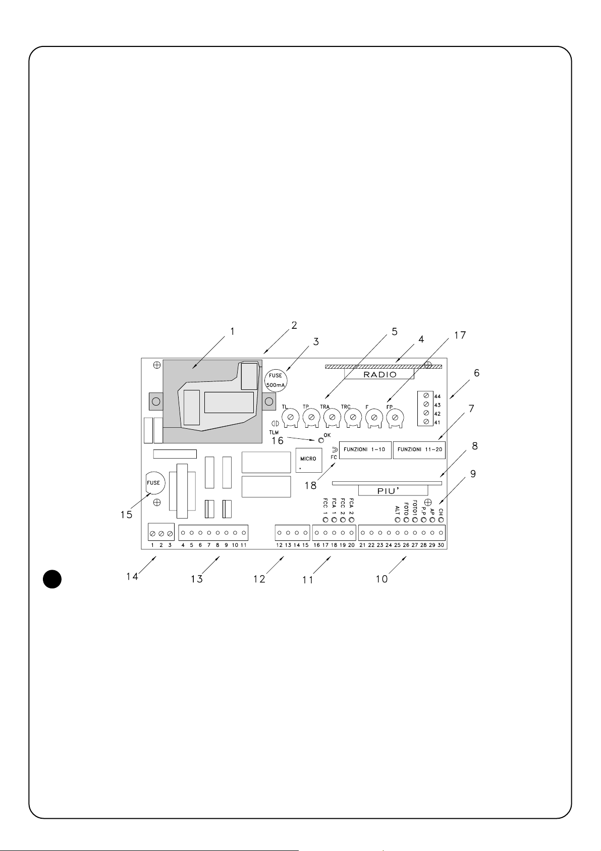
Before you start installing the unit and wiring it, here is a brief description of the most important elements on the card.
The task of the OK LED (16) is to signal the correct functioning of the internal logic; it must flash at 1 second intervals and indicates that the
internal microprocessor is working and waiting for commands. Whenever there is a variation in the state of the inputs (10-11) or of the function dip-switches (7), a double, quick flashing is generated even if the effects of the variation are not immediate.
When the unit is powered, the luminous indicators (9) on the inputs turn on if that particular input is active and if there is a control voltage of
24 Vac. As a rule, the LEDs on the safety device inputs STOP, PHOTOCELL and PHOTOCELL 1 and those on the limit switches are always
on while those on the STEP-BY-STEP, OPEN and CLOSE are normally off.
1. Power transformer (only A6)
2. Plugs for external autotransformer (only A6F or A700F)
3. 500 mA rapid fuse on 24 Vac power
4. Plug for RADIO card
5. Times adjustment trimmers
6. Aerial terminal board and 2nd RADIO channel output
7. Dip-switch to select functions
8. Plug for the PIU’ card (only A700F)
9. Indicator LEDs to signal state of the inputs
10. Terminal board for inputs of safety devices and controls
11. Terminal board for limit switch inputs (only A700F)
12. Terminal board for electric lock (only A6F or A700F) and Pho-
totest outputs (only A700F)
13. Terminal board for flashing lamp and motor outputs
14. Power terminal board
15. Rapid fuse (5A 230Vac) or (6.3A 120Vac) power
16. OK LED
17. Force adjustment trimmer
18. FC jumper for limit switch with NO contacts
2) Product description and applications
1
Page 5
5
GB
2.1) Operating limits
Chapter 9 “Technical Characteristics” provides the only data needed to determine whether the products are suitable for the intended application.
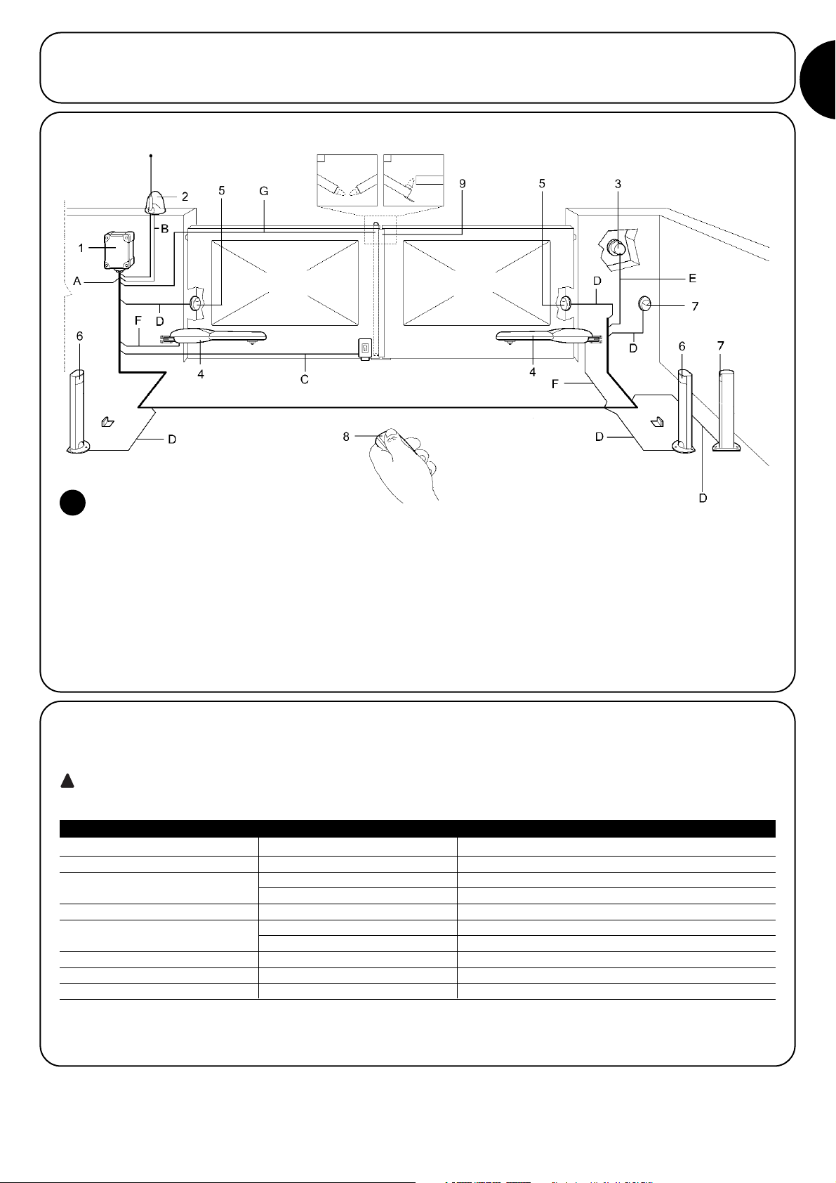
2.2) Typical system
NOTE: This diagram only shows a possible application of the unit and should be considered merely as an example. Only an in-depth analy-
sis of the risks of the “Machine” gate and a proper evaluation of the end user requirements will be able to establish how many and which elements must be installed.
1. Control Unit
2. Flashing light with incorporated aerial
3. Key-operated selector switch
4. Motors
5. Couple of photoelectric cells PHOTO
6. Couple of photoelectric cells PHOTO 1
7. Couple of photoelectric cells PHOTO 2
8. Radio transmitter
9. Sensitive edge
2
2.3) List of cables
The typical system shown in figure 2 also states the cables required for connection of the various devices, the specifications of which are
provided in table 1.
The cables used must be suitable for the type of installation; for example, an H03VV-F type cable is recommended
for indoor applications, while H07RN-F is suitable for outdoor applications.
!
Note 1: power supply cable longer than 30 m may be used provided it has a larger gauge, e.g. 3x2,5mm2, and that a safety earthing sys-
tem is provided near the automation unit.
Connection Cable type Maximum admissible length
A: Electrical power line N°1 cable 3x1,5mm
2
30m (note 1)
B: Flashing light with aerial N°1 cable 2x0,5mm
2
20m
N°1 shielded cable type RG58 20m (less than 5m recommended )
C: Electric lock N°1 cable 2x1mm
2
20m
D: Photocells N°1 cable 2x0,25mm2(Tx) 30m
N°1 cable 4x0,25mm2(Rx) 30m
E: Key-operated selector switch N°1 cable 4x0,25mm
2
30m
F: Connection to the motors. N°1 cable 4x1,5mm
2
10m
G: Connection to sensitive edge N°1 cable 2x0,25mm
2
30m
Table 1: List of cables
Page 6

6
3.2) Fixing the control unit
Insert the two screws in the upper holes provided, sliding them on the guide as in fig. 3a and partly screwing them in. Turn the control unit
through 180° and perform the same operation with the other 2 screws. Fix the control unit on to the wall.
Fix the cover on the desiderd part (with opening on the right or left), press firmly on the arrows.
To remove the cover, press with a screwdriver on the join and push upwards at the same time.
The installation must be carried out by qualified personnel in compliance with current legislation, standards and regulations,
and the directions provided in this manual.
!
3) Installation
3.1) Preliminary checks
Before proceeding with the installation:
• Check that all the materials are in excellent condition, suitable for
use and compliant with current standards.
• Ensure that the structure of the gate is suitable for automation.
• Ensure that the mounting positions of the various devices are protected from impact and that the mounting surfaces are sufficiently
sturdy.
• Install cable or pipe leads only at the bottom of the unit; for no reason whatsoever must the side and top walls be perforated. The
cables must only enter the unit from the bottom!
• Components must never be immersed in water or other liquids.
• Keep away from heat sources and open flames; in acid, saline or
potentially explosive atmosphere; this could damage A6 – A6F –
A700F and cause malfunctions or hazardous situations.
• If there is an access door in the leaf, or within the range of movement of the gate, make sure that it does not obstruct normal travel. Mount a suitable interlock system if necessary.
• Only connect the control unit to a power supply line equipped with
a safety grounding system.
• The power supply line must be protected by suitable magnetothermal and differential switches.
• A disconnection device must be inserted in the power supply line
from the electrical mains (the distance between the contacts must
be at least 3.5 mm with an overvoltage category of III) or equivalent system, for example an outlet and relative plug. If the disconnection device for the power supply is not mounted near the
automation, it must have a locking system to prevent unintentional, unauthorised connection.
3a 3b 3c 3d
3.3) Diagram of the connections
Once the unit, the actuators, the control (key selector or push button panel) and safety (emergency stop, photoelectric cells, sensitive edges
and flashing light) elements have been installed, you can now do the wiring, following the instructions given below.
To safeguard the operator and avoid damaging the components while you are wiring, whether it is low voltage (230 -120Vac) or extra low
voltage (24 V) or if you are plugging in the various cards:
The unit must, under no circumstances, be electrically powered.
We also wish to remind you that if the inputs of the NC (Normally Closed) contacts are not used they should be jumpered; if there is more
than one then they should be placed in SERIES with one another; if the inputs of the NO (Normally Open) contacts are not used they should
be left free and if there is more than one then they should be placed in PARALLEL with one another. The contacts must be of the mechanical type and free from any potential; no connections are allowed like those defined as “PNP”, “NPN”, “Open Collector” etc., etc.
Carry out the necessary connections, following the diagram in Fig. 4 and the following description of the connections.
Remember that there are specific standards that must be complied with both as regards the safety of the electrical systems and as
regards automatic gates
!
!
Page 7

7
GB
3.4) Description of the connections
Here is a brief description of the possible connections of the unit to the outside:
1...3 : 230 - 120 Vac
4-5 : Flashing light = Output for connection to the 230 -120 Vac flashing light, maximum lamp power 100 W
6...8 : Motor 1 = Output for connection to the 1st motor 230 - 120 Vac
9...11 : Motor 2 = Output for connection to the 2nd motor 230 - 120 Vac
Note: Motors 1 and 2 only differ in the start delay; the 1st motor is connected to the opening delay time “TRA” while the 2nd motor is connected to the closing delay time “TRC”. If the delays are unnecessary there is no difference between the motors.
The following terminals are found only on the
A700F and A6F version:
12-13 : Electric lock = 12 Vac output to activate the electric lock, 25 W maximum power
You will find the following terminals only on the
A700F version:
14-15 : Phototest = 24 Vac output to feed photoelectric cell transmitters, 100 mA max.
16 : Common = Common for limit switch inputs (same as the other common, terminal 23)
17 : C1 limit switch = Close limit switch input for motor 1
18 : A1 limit switch = Open limit switch input for motor 1
19 : C2 limit switch = Close limit switch input for motor 2
20 : A2 limit switch = Open limit switch input for motor 2
21-22 : 24 Vac = 24 Vac output to feed accessories (Photocell, Radio, etc.) 200 mA max.
23 : Common = Common for all inputs (terminal 22 can also be used as Common
24 : Gate Open Indicator = 24 Vac output for gate open indicator, 2 W max. indicator power
25 : Stop = Input with STOP function (Emergency, shutdown or extreme safety)
26 : Photocell = Input for safety devices (photoelectric cells, pneumatic edges)
27 : Photocell 1 = Input for another safety device (photoelectric cells, pneumatic edges)
28 : Step-by-Step = Input for cyclic functioning (OPEN STOP CLOSE STOP)
You will find the following terminals only on the
A700F version:
29 : Open = Input for opening (it can be controlled by a timer)
30 : Close = Input for closing
41-42 : 2° Radio Ch = Output for the second radio receiver channel if there is one
43-44 : Antenna = Input for the radio receiver antenna
There are an additional two slots on the unit card for optional cards:
RADIO = Slot for Nice radio receivers
PIU = Slot for PIU’ expansion card (only on the A700F version)
We recommend waiting until installation is complete to plug in the optional cards RADIO or PIU’ and only after having checked that the system is working properly. The optional cards are not necessary for the working of the system and if they are used they make troubleshooting
more complex.
The highlighted part is only found on
the A700F version.
The highlighted part is found on the
A6F and A700F versions.
4
Antenna
2° Radio
Ch
FUNCTIONS 11-20FUNCTIONS 1-10
Phototest
24 Vac, Max 100 mA
230-120 Vac “L”
12 Vac, Max 25 W
Motor 2 Close
Motor 2 Common
Motor 2 Open
Motor 1 Close
Motor 1 Common
Motor 1 Open
Flashing light 230-120 Vac
Max 100W
230-120 Vac “N”
Electric lock
Common
C1 limit switch Close
A1 limit switch Open
C2 limit switch Close
A2 limit switch Open
Photocell
Stop
Gate Open Indicator
Common
24 Vac output (accessories)
Max 200 mA
Open
Step-by-Step
Photocell 1
Close
Page 8

8
3.5) Notes about connections
For the most part, connections are easy; a lot of them are direct connections to a single user point or contact but some are a little more
complex:
All the single-phase asynchronous motors need a capacitor for them to work properly; some gearmotors have this capacitor already connected inside while others have to have the capacitor connected externally. In this case, the capacitor must be connected between the
motor’s OPEN and CLOSE phases. To be more practical the capacitor should be connected directly inside the unit in the spaces left for it.
The following is applicable only to the A700F version
A particular description is given about the “Phototest” output which
is nothing else but the best possible solution in terms of reliability as
regards safety devices. Each time a manoeuvre is activated the relevant safety devices are checked and only if everything is in order will
the manoeuvre start.
Should the test be unsuccessful (the photocell is blinded by the sun,
cables have short circuited, etc.) the failure is found and the
manoeuvre is not carried out.
All this is possible only by using a certain configuration in the safety
devices’ connections (Fig. 5).
As you can see from the wiring diagram, while the receivers of the
photoelectric cells PHOTOCELL, PHOTOCELL 1 (and PHOTOCELL
2 if it exists - on the PIU’ card) are normally supplied by the accessories’ 24 V a.c., the transmitters take their power from the phototest output. When movement is requested, first of all it is verified
that all the receivers involved in the movement give their consent
then the phototest output is turned off after which it is checked that
all the receivers signal the fact by removing their consent; lastly, the
phototest output is reactivated and consent of all the receivers is verified once again.
As you can see, synchronism has been activated on the two transmitters by cutting the jumpers, this is the only way to guarantee that
the two pairs of photoelectric cells do not interfere with one another.
Check the instructions in the photocell manual regarding synchronised functioning.
If the “PHOTOCELL” input is not going to be used its terminal must be jumpered via the 24 VAC relay connected on the
PHOTOCELL TEST output.
• As a rule gearmotors are used on 2-wing gates that do not need limit switches; it is normal practice to install mechanical stops that stop
movement in the point wanted. There is also a “Working Time” trimmer on the control unit that is usually set for a time slightly longer than
the time actually needed for the complete manoeuvre. When the gate reaches the mechanical stop the motor stops and remains under
stress for the rest of the time; the motors are always designed to withstand this kind of stress without any trouble, especially if the force is
set at values lower than 100%.
• In some installations, like for instance in the case of two sliding gates or if you wish to exploit the positioning function, limit switches might
be needed. In the majority of cases, if limit switches are used they are the normally closed “NC” type so that if a failure does occur it will
cause the motor to stop without the gate getting stuck. In other cases, like for example when magnetic type contacts are used, it is possible that normally open type limit switches have to be used “NO”. To enable the control unit to use NO type limit switches you have to cut
the FC jumper on the card (Fig. 2). This jumper can also be cut even if limit switches are not used which will avoid having to install the relative jumpers.
• Depending on the type of gearmotor and on the function you wish to achieve, the limit switches can be used as indicators of the end of
travel point (limit switch function) or to signal the starting point of the positioning function. If they are used for positioning, they are normally installed at an angle of 10-20° from the stopping point and they indicate the point at which an even weaker force will be applied to the
motors, adjustable by means of the POSITIONING FORCE trimmer, so the gate will stop mechanically as gently as possible.
5
If the gate has 2 wings that could get bump into each other if, when opening, they start simultaneously or, when closing, one moves on top
of the other, you will have to readjust the Opening Delay Time trimmer “TRA” or the Closing Delay Time trimmer “TRC”. These trimmers can
be adjusted to your liking, although as a rule the TRA is set for the time actually needed and the wing moved by the 2nd motor is already
out of the way when the 1st motor starts.
4) Adjustments
TLM = Increased Working Time
TL = Working Time
TP = Pause Time
TRA = Opening Delay Time
TRC = Closing Delay Time
F = Force
FP = Positioning Force
Page 9
9
GB
The TRC trimmer must be adjusted so that when closing, the wing
moved by the 2nd motor always reaches the end only after the 1st
motor has terminated the closing manoeuvre.
The Closing Delay Time can be used as a safety margin of 50 cm in
closing.
Now select the “Semiautomatic” functioning mode by positioning
dip-switch no. 1 in ON and adjust the Working Time trimmer to
about halfway of the travel distance. Having made these adjustments, run a complete opening cycle followed by a complete closing cycle and readjust the Working Time trimmer as needed so that
there is enough time for the whole manoeuvre leaving a margin of
about 2 to 3 seconds. If the trimmer is on maximum and there still is
not enough time, the TLM jumper on the printed circuit near the trimmer can be cut to provide more working time.
In some types of actuators, for example the oleodynamic type, force
is adjusted directly on the actuator; consult the relative instruction
manual regarding adjustment and leave force adjustment inside the
unit on maximum.
For all the types of actuators that do not have a force adjustment
device it is possible to exploit the adjustment system of the force
inside the unit: on the basis of the unit version used, follow the relative instructions.
The following refers only to the A6 version
There is a FORCE trimmer on the unit which is usually set for maximum force; with a screwdriver turn the trimmer counterclockwise to
reduce motor force until you reach the value established by the standards.
The following refers only to the A6F e A700F versions
There is an adequately powered autotransformer on the unit with
intermediate sockets on the primary winding and which can be
selected by means of a special FORCE commutator; turn the commutator round to the most suitable position to reduce motor force
until you reach the value established by the standards.
Maximum force is provided whatever system is used to adjust the
force for the initial movement phase and for a duration of 1.5 seconds; only after this time, defined “Inrush”, is the force established.
If you have chosen the automatic functioning mode (dip-switch No.
2 ON), the end of the opening manoeuvre is followed by a “pause”
time at the end of which a closing manoeuvre follows automatically.
The time the gate stays open can be adjusted with the PAUSE TIME
trimmer for the length of time you want, without any limits. An automatic closing manoeuvre and the relative pause time are activated
also in the semiautomatic functioning mode when, in closing, the
triggering of a safety device will cause the gate to reverse direction.
Only now, when all the adjustments have been made, do we advise
you to plug in the radio receiver if you have one, reminding you that
the commands it sends are sent to the STEP-BY-STEP input.
4.1) Functioning modes
Note: some of the parts described below refer only to the A700F
version.
In the manual functioning mode the OPEN input consents to the
opening manoeuvre, the CLOSE input consents to the closing
manoeuvre, the STEP-BY-STEP consents to an alternating closing
and opening manoeuvre; as soon as the command in input stops,
movement stops. If, during an opening manoeuvre, the limit switches trigger or if PHOTOCELL 2 (on the PIU’ card) fails to give consent,
movement will stop; during a closing manoeuvre, on the other hand,
movement will also stop if there is no consent from PHOTOCELL
and PHOTOCELL 1. Whether in the opening or closing phase movement, the activation of the STOP command will cause an immediate
stopping of movement and a short reverse run.
When a movement is stopped you have to stop the command in
input before a new command has the chance to start a new movement. When in one of the automatic functioning modes (semiautomatic, automatic or close always), a command pulse on the OPEN
input will cause an opening manoeuvre; if the command persists
once fully open, the gate will stay in this position for a “infinite” pause
time; only when the command stops can the gate close again.
A pulse on the STEP-BY-STEP causes an alternating closing and
opening manoeuvre. A second pulse on the STEP-BY-STEP or on
the input that started movement, will cause a Stop.
Both in the opening and closing phases, the activation of the STOP
command will cause an immediate stopping of movement and a
short reverse run.
If, instead of a pulse on a command input a continuous signal is
maintained, a state of “priority” will be created where the other command inputs are disabled (useful if you want to connect a timer or a
Night-Day selector). If you have chosen the automatic functioning
mode, subsequent to an opening manoeuvre there will be a pause
followed by a closing manoeuvre. If, during the pause time, either the
PHOTOCELL or PHOTOCELL 1 triggers, the timer will be reset with
a new pause time; if, on the other hand, there is a STOP during the
pause time, the reclosing function is cancelled and there is a STOP
state. Triggering of PHOTOCELL or PHOTOCELL 1 has no effect during an opening manoeuvre but PHOTOCELL 2 (on the PIU’ card) will
cause reversal of movement; the triggering of PHOTOCELL or PHOTOCELL 1 during a closing manoeuvre will cause reversal of movement followed by a pause time and then a reclosing manoeuvre.
The unit comprises a set of microswitches used to operate various
functions so as to render the system more suitable to user needs
and safer in the different ways of usage. All functions are activated
by placing the dip-switch in the “ON” position while they will not be
activated if the corresponding dip-switches are “OFF”; some functions do not have an immediate effect and only have sense in certain
conditions like, for instance, the No. 12 function “Flashing also in
pause time” which is only active with automatic closing and if the
manoeuvre is not interrupted with a STOP command.
ATTENTION: some of the programmable functions are linked to
safety aspects, very carefully evaluate the effects of a function and
see which function gives the greatest possible level of safety.
When servicing a system, before you modify a programmable function, ascertain the reason why, during installation, certain choices
were made and then verify if, with the new programming, safety will
be impaired.
!
5) Programming
Page 10

10
5.1) Programmable functions
With the FUNCTIONS dip-switch you can select the various functioning modes and add the functions required according to this table:
Switches 1-2: Off Off = “Manual” movement (Man Present)
On Off = “Semiautomatic” movement
Off On = “Automatic” movement (Automatic Closing)
On On = “Automatic+Always Closes” movement
Switch 3 On = Condominium functioning mode < Not available in the Manual mode>
Switch 4 On = Preflashing
Switch 5 On = Recloses immediately after Photocell < Only in the Automatic mode>
Switch 6 On = Photocell 1 also in Opening
Switch 7 On = Gradual start
Switch 8 On = Gradual stop
Switch 9 On = Water hammering
Switch 10 On = Courtesy light on flashing
There is a second set of dip-switches with other functions in the
A700F version:
Switch 11 On = Positioning function < only with the aid of the limit switch >
Switch 12 On = Flashing also in Pause < Only in the Automatic mode>
Switch 13 On = Pressure holding
Switch 14 On = Gate Open Indicator with proportional flashing
Switch 15 On = Phototest operation
Switch 16 On = Photocell and Photocell 1 also in opening
Switch 17 On = Photocell and Photocell 1 at start of the opening manoeuvre
Switch 18 On = Misses STOP in opening
Switch 19 On = Misses STOP in closing
Switch 20 On = CLOSE becomes PEDESTRIAN OPEN
We wish to remind you that the functions that are possible only in certain cases are indicated with the notes between the symbols “<>” following the description of the function.
Of course, if a dip-switch is “OFF” the function described will not be activated.
5.2) Description of the functions
Here is a brief description of the functions that can be added by
switching the relative dip-switch “ON”.
Switches 1-2: Off Off = “Manual” movement (Man Present)
On Off = “Semiautomatic” movement
Off On = “Automatic” movement
(Automatic Closing)
On On = “Automatic+Always Closes” movement
In the “Manual” functioning mode, the gate will move only as long as
the key to command (it is held down).
In the “Semiautomatic” functioning mode a command pulse is
enough to carry out the whole movement up to the mechanical stop
or until the limit switch triggers. In the “Automatic” functioning mode
an opening manoeuvre is followed by a pause and then a closing
manoeuvre.
The “Always Closes” function comes into play subsequent to a temporary power cut; if the gate is open a closing manoeuvre starts
automatically preceded by 5 seconds of preflashing.
Switch 3: On = Condominium function (not available in the Manual
mode)
In the Condominium functioning mode, once an opening manoeuvre
has started it cannot be interrupted by other command pulses on
STEP-BY-STEP or OPEN until the gate has finished opening. During
a closing manoeuvre, a new command pulse will stop the gate and
reverse the direction, opening the gate.
Switch 4: On = Preflashing
With a command pulse first of all flashing is activated followed by
movement 5 seconds later (2 seconds if on manual).
Switch 5: On = Recloses straight after Photocell (only if in the Automatic mode)
With this function the gate can be kept open only for the length of
time needed for transit; in fact, it will close automatically always 5
seconds after the last object has passed by the Photocell or Photocell 1, irrespective of the programmed Pause Time.
Switch 6: On = Photocell 1 also in opening
This is the only function that makes the photoelectric cells PHOTOCELL and PHOTOCELL 1 different. As a rule the safety devices
PHOTOCELL and PHOTOCELL 1 will only trigger in the closing
manoeuvre, having no effect whatsoever in the opening manoeuvre.
If dip-switch No. 6 is turned “ON”, the PHOTOCELL will continue
triggering only in the closing manoeuvre but PHOTOCELL 1 will trigger also in the opening manoeuvre, causing an interruption in the
movement. In the semiautomatic or automatic mode, movement will
restart after the last object has passed by PHOTOCELL 1
This is useful to stop the gate in the opening manoeuvre when, for
example, a vehicle nears the gate from the inside, which is in the
direction of the manoeuvre, without stopping movement when the
vehicle nears the gate from the outside.
Switch 7: On = Gradual start
Movement starts gradually, sending an increasing force to the motor
forming a ramp that lasts about 1 second, this guarantees a jolt-free
start. (Not recommended on METRO gear motor).
Switch 8: On = Gradual stop
When movement finishes, a gradual stop is carried out, sending a
diminishing force to the motor with a decrement that lasts about 1
second, this guarantees a jolt-free stop.
Page 11

11
GB
For obvious safety reasons, when STOP, PHOTOCELL and PHOTOCELL 1 or PHOTOCELL 2 (on the PIU’ card) or one of the limit switches trigger, there is no gradual stop, being replaced by an ordinary stop.
Switch 9: On = Water hammering
When reversible actuators are used, and hence the gate does not
remain closed with the mere thrust of the motors, an electric lock
has to be installed (see actuator instructions as to use).
Consequently the natural thrust applied to the electric lock might
tend to leave the gate wings slightly ajar, sometimes this thrust is so
great that it keeps the electric lock’s triggering mechanism blocked.
With the water hammering function on, a short closing cycle is activated prior to an opening manoeuvre but it causes no movement
since the gates are already up against the mechanical closing stop.
In this way, when the electric lock is activated, without any force and
therefore ready to trigger.
Switch 10: On = Courtesy light on flashing
In certain cases it might be necessary to illuminate the gate movement area and often it is required that the light turn off automatically
soon after the gate has finished its manoeuvre. This function is commonly referred to as the “Courtesy light”. By connecting appropriate
light fixtures to the same output as the flashing light (for a maximum
total capacity of 100 W) and activating this function, the output will
remain active, illuminating the area for the duration of the manoeuvre
plus 60 seconds.
Only on the
A700F version there is a second set of dip-switches
with other functions:
Switch 11: On = Positioning function (only with the use of the limit
switches)
The limit switches can be used, instead of for signalling movement
limits, for indicating the point in which positioning starts. Normally
when the positioning function is used, the limit switches are installed
at an angle of 10-20° before the mechanical stop. This means that
when the moving wing reaches the limit switch, a reduced force will
be sent to the motor which can be adjusted with the “Positioning
Force” trimmer for an additional 3 seconds so that the gate can
reach the mechanical stop as gently as possible.
Switch 12: On = Flashing also in Pause
The flashing light is normally activated only during the opening and
closing manoeuvres, this function means that the flashing light
remains active also during the Pause Time to signal the “closing
soon” condition.
Switch 13: On = Pressure holding
In the oleodynamic actuators the thrust to keep the gate closed is
developed inside a hydraulic circuit which is constantly under pressure. When time and wear reduce the hydraulic circuit’s sealing
effect it could happen that after a few hours the internal pressure
drops and there is the risk of the gate opening slightly.
If the Pressure Holding Function is activated, after 4 hours, and then
for each 4 hours that the gate is closed, a brief closing manoeuvre is
activated with the sole aim of recharging pressure in the hydraulic
circuit.
NOTE: the “Water hammering” and “Pressure Holding” functions
only have sense and are carried out if the gate is closed.
The internal logic considers the gate closed if the relative limit switch,
FCC, has triggered or, if the limit switches are not used, by the fact
that the previous closing manoeuvre was concluded regularly by the
end of the working time.
Switch 14: On = Gate Open Indicator with proportional flashing
The Gate Open Indicator normally signals gate condition as follows:
Off: Gate completely closed
On: Gate only partly open
Slow flashing: Gate starting to open
Fast flashing: Gate closing
The flashing of the indicator light during movement can be rendered
proportional, going gradually from slow to fast and vice versa; this
will provide an indication about the opening and closing state.
Switch 15: On = Phototest activation
This switch starts a test of the photoelectric cells before each movement begins; thus doing, the chance of malfunctioning is eliminated
and plant safety is augmented. In order to take advantage of the
Phototest function the photoelectric cell transmitters must be connected to the corresponding output (see: Note on connections).
Switch 16: On = Photocell and Photocell 1 also in opening
The safety devices PHOTOCELL and PHOTOCELL 1 normally trigger only in the closing manoeuvre; if dip-switch no. 16 is activated,
triggering of the safety devices will cause movement to be interrupted even in the opening phase; if it is set on Semiautomatic or Automatic, movement in the opening direction will start again as soon as
the last object has passed by the photoelectric cell.
Switch 17: On = Photocell and Photocell 1 at the beginning of the
opening manoeuvre
As a rule the safety devices PHOTOCELL and PHOTOCELL 1 are
only active in the closing manoeuvre and not in the opening manoeuvre because the former is the most dangerous. In some countries
there are standards that impose the control of the safety devices at
least at the beginning also of the opening manoeuvre. If such standards have to be complied with or if you wish to increase the level of
safety, it is possible to activate the function and consequently check,
prior to starting movement, consent given by the PHOTOCELL and
PHOTOCELL 1 safety devices, and only then start movement.
Switch 18: On = Misses STOP in opening
The Step-by-Step cycle is normally: OPEN-STOP-CLOSE-STOP.
With this function on, Step-by-Step becomes: OPEN-CLOSESTOP- OPEN, while the Open input loses its possibility to STOP.
Switch 19: On = Misses STOP in closing
This is similar to the previous function but concerns the closing
cycle, hence the Step-by-Step cycle becomes: OPEN-STOPCLOSE-OPEN, while the Close input loses its possibility to STOP.
NOTE: By turning dip-switches 18 and 19 ON, the step-by-step
cycle becomes: OPEN-CLOSE-OPEN, losing its possibility to STOP.
Switch 20: On = CLOSE becomes PEDESTRIAN OPEN
It could happen that you do not need to open the gate fully like, for
instance, when a person has to transit; in such a case, the
PEDESTRIAN OPEN function is useful which opens just the one
gate, connected to the 2nd motor, leaving the other one closed.
This type of opening is activated by the CLOSE input which loses its
original function, becoming like the Step-by-Step input, but only for
the opening of one gate. We ought to stress that the pedestrian
opening cycle will only start if the gate is closed; if the gate is moving or open, the input pulse will have no effect.
ACCESSORY: “PIÙ” EXPANSIONS CARD
The electronic unit is equipped with all the main functions required of
a normal automation, in the A700F version there is also the possibility of adding the optional PIU card by means of which unit performance can be enhanced.
Page 12

12
The following is only applicable to the A700F version
The card must be plugged into the corresponding connector on the unit and consequently the following are available on the card terminals:
• The following inputs: Photocell 2 = Safety device that triggers in the opening manoeuvre
Partial Opening = It carries out an opening manoeuvre in a shorter time
• The following outputs: Red = Red light of the traffic light
Green = Green light of the traffic light
Alarms
Electric lock = Electric lock command (seeing as the unit is already equipped with this output, the
function has been modified to “Suction Pad” to connect the magnetic holding
devices that are used as an alternative to the electric lock)
Courtesy light = The command of a lamp with the functions of a courtesy light
Note: The outputs can only command small capacity loads (indicator lamps, relays, etc.)
• and the following adjustments: Partial Time = Time for partial opening
Courtesy Time = Time for the courtesy light
The complete features and instructions for using the card are given in the relative instruction manual.
Once the motor and various accessories have been connected you
can now check all the connections and test the plant.
This is the most important stage in the automation system installation procedure in order to ensure maximum safety levels. Testing
can also be adopted as a method of periodically checking that all the
various devices in the system are functioning correctly.
Testing of the entire system must be performed by qualified and
experienced personnel who must establish which tests to conduct
on the basis of the risks involved, and verify the compliance of the
system with applicable regulations, legislation and standards, in particular with all the provisions of EN standard 12445 which establishes the test methods for automation systems for gates.
We recommend working in the manual mode with all the functions
deactivated (dip-switches OFF); in all cases, when you are working
in the manual mode and you release the control key the motor will
stop immediately. Also check that all the adjustment trimmers are on
minimum (turned in the counterclockwise direction), only the FORCE
trimmer (on A6) or the FORCE commutator (on A6F and A700F)
can be positioned on maximum; the Positioning Force trimmer (on
A700F) must be positioned halfway.
Each component of the system, e.g. safety edges, photocells, emergency stop, etc. requires a specific testing phase, we therefore recommend observing the procedures shown in the relative instruction
manuals.
Ensure that the instructions outlined in this manual and in particular
in chapter 1 "WARNINGS" have been observed in full.
A) Unlock the gate and take the wings to the halfway point and then
lock them, now the gate is free to move in either the opening or
closing direction.
B) Power the unit and check that voltage between terminals 1-2 and
1-3 is 230 / 120 Vac and 24 V a.c. between terminals 21-22.
The following refers only to the
A700F version
C) Check that voltage on terminals 14-15 is 24 V a.c. for powering
the photoelectric cell transmitters.
As soon as the unit is powered the indicator lights (LEDs) on the
active inputs should light up; in addition, the “OK” LED should start
flashing almost immediately afterwards at regular intervals. If none of
this happens, switch power off and check connections more carefully.
• The task of the “OK” LED, in the centre of the card, is to signal
the state of the internal logic: regular flashing at 1 second inter-
vals means the internal microprocessor is working and waiting for
commands. On the other hand, when the same microprocessor
recognises a variation in the state of an input (be it a command
input or function dip-switch), a double, quick flashing is generated even if the effects of the variation are not immediate. Extra fast
flashing for 3 seconds means that the unit has just been powered
and is carrying out a test of the internal parts; lastly an irregular,
non constant flashing means that the test was unsuccessful and,
consequently, there is a failure.
D) Now check that the LEDs of inputs with NC type contacts are on
(all the safety devices active) and that the LEDs of inputs with NO
type contacts are off (no command present); if this does not happen check connections and effectiveness of the various devices.
E) Check that all the safety devices on the plant are working prop-
erly (emergency stop, photoelectric cells, pneumatic edges, etc.);
each time they trigger the corresponding STOP, PHOTOCELL or
PHOTOCELL 1 should turn off.
• This is one of the most important checks and must be done with
great care, in actual fact the “active” safety of the gate machine
depends on the correct functioning of the safety devices. If the
flashing light is an excellent instrument for signalling the state of
danger and the torque limiting devices are an excellent means to
minimise damages, only a correct installation of the safety
devices will make it possible to block the automatism before it
can cause any damage.
The following refers only to the
A700F version
F) You will have to check correctness of the connections if limit
switch inputs are used. Move the wings one at a time and check
that once the point wanted is reached, the corresponding limit
switch triggers, turning the relative LED off on the unit (or turning
it on if NO limit switches are installed).
• Now is the time to check whether movement occurs in the right
direction, that is, to see whether movement set on the unit corresponds to that of the gates.
This check is of paramount importance, if the direction is wrong
in some cases (in the semiautomatic functioning mode for
instance), the gate might appear to be working properly; in fact,
the OPEN cycle is similar to the CLOSE cycle but with one basic
difference, the safety devices are ignored in the closing manoeuvre which is normally the most dangerous, and they will trigger in
the opening manoeuvre causing the gate to reclose up against
the obstacle with disastrous results!
!
6) Testing
}
Page 13
13
GB
G) To see whether or not rotation direction is correct, give a short
pulse to the Step-by-Step input; the first manoeuvre the unit will
carry out after being powered on is always an OPEN one, so simply verify that the gate starts opening; if movement is wrong you
must proceed as follows:
1 - Turn power off
2 - Reverse the “OPEN” and “CLOSE” connections of the motor
or motors that are turning in the wrong direction.
Once this has been done, check if rotation direction is now correct,
repeating the procedure described in point “G”.
H) Having checked all connections and motor rotation direction, it is
possible to try a complete movement of the actuators, we rec-
ommend that you always work in the manual mode with all func-
tions deactivated. If you use the Step-by-Step as the command
input, the first movement (after turning on) should be an opening
one. By means of the command inputs, move the gate until it
reaches the open point; if everything goes normally you can then
go on to the closing manoeuvre and move the gate until it reach-
es the stop point.
It is worthwhile carrying out several open and close manoeuvres so
you can evaluate any defects in the automation’s mechanical structure and also to pinpoint any specific points of friction.
I) Now test triggering of the safety devices; in the opening manoeu-
vre PHOTOCELL and PHOTOCELL 1 have no effect but in the
closing manoeuvre they will stop movement. If the PIU’ card is
plugged in try functioning of the PHOTOCELL 2 input, in the closing manoeuvre it has no effect while in the opening manoeuvre it
will stop movement. The devices connected to the STOP input
act both in the opening and closing manoeuvres, stopping movement each time.
L) The hazardous situations caused by the movement of the leafs
have been safeguarded by limiting the force of impact, the impact
force must be measured according to EN Standard 12445. If the
control of the “motor force” is used to assist the system for the
reduction of the impact force, try to find the adjustment to obtain
optimal results.
6.1) Commissioning
Commissioning can take place only after all the testing phases of the
control unit and the other devices have been completed successfully. It is not permissible to execute partial commissioning or to enable
use of the system in makeshift conditions.
1. Prepare and store for at least 10 years the technical documentation for the automation, which must include at least the following:
assembly drawing of the automation, wiring diagram, analysis of
hazards and solutions adopted, manufacturer's declaration of conformity of all the devices installed (for A6 - A6F - A700F use the
annexed CE declaration of conformity); copy of the instruction manual and maintenance schedule of the automation.
2. Affix a dataplate on the gate providing at least the following data:
type of automation, name and address of manufacturer (person
responsible for the “commissioning”), serial number, year of manufacture and “CE” marking.
3. Post a permanent label or sign near the gate detailing the operations for the release and manual manoeuvre.
4. Prepare the declaration of conformity of the automation system
and deliver it to the owner.
5. Prepare the “Instructions and warnings for the use of the automation system” and deliver it to the owner.
6. Prepare the maintenance schedule of the automation system and
deliver it to the owner (this must provide all directions regarding
the maintenance of the single automation devices).
7. Before commissioning the automation system inform the owner in
writing regarding residual risks and hazards (e.g. in the “Instructions
and warnings for the use of the automation system”).
7.1) Maintenance
The automation must undergo maintenance work on a regular basis,
in order to guarantee prolonged lifetime.
The maintenance operations must be performed in strict
compliance with the safety directions provided in this
manual and according to the applicable legislation and
standards.
If other devices are present, follow the directions provided in the corresponding maintenance schedule differents from A6 - A6F - A700F.
1. Is requires scheduled maintenance work every 6 months or
10,000 manoeuvres (max.) after previous maintenance.
2. Disconnect all power supplies.
3. Check for any deterioration of the components which form the
automation, paying particular attention to erosion or oxidation of the
structural parts. Replace any parts which are below the required
standard.
4. Connect the electric power sources up again, and carry out the
testing and checks stated in Paragraph “6 Testing”.
This charter provides information about how to draw up a maintenance schedule, and the disposal of A6 – A6F –A700F.
!
7) Maintenance and Disposal
Page 14

14
7.2) Disposal
As in the case of installation, at the end of the product lifetime, disposal procedures must be carried out by qualified personnel.
This product comprises various types of materials, some of which
can be recycled while others must be disposed of. Check information on the recycling and disposal procedures according to local legislation for this product category.
Some parts of the product may contain pollutant or
hazardous substances; if disposed of into the environment
these may constitute a serious risk of damage to the environment and public health.
As indicated by the symbol in figure never dispose of this product in domestic
waste. Apply “classified waste collection”
procedures for disposal in accordance
with local regulations or return the product to the retailer when purchasing a new
model.
Local regulations may envisage serious fines in the event of illegal
disposal of this product.
!
The following optional accessories are available for A6 – A6F – A700F:
“PIU” CARD:
The unit already has all the functions used in a normal installation but to meet the demands of use in particular installations
NICE has designed an optional card “PIU” used to add new functions like traffic light signalling, courtesy light, lock, Photocell2, partial opening of the two gates, and so on.
“RADIO” CARD:
There is a connector in the unit for plugging in a radio card used to act on the STEP-BY-STEP input and thus control the unit remotely by
means of a transmitter.
Consult the Nice S.p.a. product catalogue for the complete and updated list of accessories.
8) Accessories
With the aim of improving products, Nice S.p.a reserves the right to modify technical characteristics at any time without notice, while maintaining the same functionalities and intended use.
All technical characteristics stated refer to an ambient temperature of 20°C (±5°C).
9) Technical characteristics
Model type: A6 -A6/V1 A6F -A6F/V1 A700F –A700F/V1
Power A6 – A6F – A700F 230 Vac ± 10%, 50 - 60 Hz
Power A6/V1 – A6F/V1 - A700F/V1 120 Vac ± 10%, 50 - 60 Hz
Maximum actuator power 230 Vac 300 W [1,3 A]
Maximum actuator power /V1 120 Vac 300 W [2,5 A]
Maximum flashing light power 100W
Maximum frequency of operating cycles unlimited
Maximum time of continuous operation unlimited
Maximun current accessories (24 Vac) 200 mA
Maximun current phototest output / / 100 mA
Gate open indicator max. power SCA (24Vac) 2 W
Maximun electric lock power 12 Vac / 15 VA 15 VA
Working time from 2,5 to 40 sec. (from 30 to 80 sec. con TLM)
Pause time from 5 to 80 sec.
TRA opening delay time 0 or from 2.5 to 12 sec.
TRC closing delay time 0 or from 2.5 to 12 sec.
Force adjustment from 0 to 100 % 30%-45%-60%-80%-100%
Operating temperature -20 ÷ 50 °C
Size 280 x 220 x 110 mm
Weight 1,7 Kg 2,7 Kg 2,7 Kg
Protection level IP55 (container undamaged)
Page 15

15
GB
Congratulations for having chosen a Nice product for your
automation system! Nice S.p.A. produces components for the
automation of gates, doors, rolling gates, roller shutters and
awnings: gearmotors, control units, radio controls, flashing
lights, photocells and miscellaneous accessories. Nice uses only
the finest materials and first-class workmanship. It focuses on
the development of innovative solutions designed to simplify the
use of its equipment, dedicating meticulous care to the study of
its technical, aesthetic and ergonomic characteristics: From the
wide range of Nice products, your installation technician will certainly have selected the one best suited to your specific requirements. However, Nice is not the producer of your automation
system, which is rather the result of a combination of operations
carried out by your installation technician, namely analysis, evaluation, selection of materials and system implementation. Each
automation system is unique. Your installation technician is the
only person who possesses the experience and professionalism
needed to set up a system capable of satisfying your requirements, a system that is safe, reliable, long lasting and built in
accordance with the regulations in force. An automation system
is not only very convenient; it also improves the level of security
in your home. Moreover, it will last for years with very little maintenance. Even though the automation system you posses meets
the safety requirements of the legislation in force, this does not
exclude the existence of a “residual risk”, i.e. the possibility that
dangers may arise, usually as a result of improper or unreasonable use. We have prepared the following list of do's and don'ts
to help you avoid any mishaps:
•Before using your automation system for the first time,
ask the installer to explain the origin of residual risks; take a few
minutes and read the users instructions manual given you
by the installer. Retain the manual for future use and deliver
it to any subsequent owner of the automation system.
•Your automation system is a machine that will faith-
fully execute your commands; unreasonable or improper
use may generate dangers: do not operate the system if there
are people, animals or objects within its range of operation.
•Children: automation systems are designed to guarantee high
levels of safety and security. They are equipped with detection
devices that prevent movement if people or objects are in the
way, guaranteeing safe and reliable activation. However, children should not be allowed to play in the vicinity of automated
systems; to prevent any accidental activations, keep all remote
controls away from children: they are not toys!
•Photocells do not constitute actual safety devices,
but safety aids. They are designed using highly reliable technology, but in extreme conditions may be subject to malfunctions or potential faults, and in certain cases these faults are not
immediately evident.
For this reason, it is good practice to observe the following:
- Transit is admitted only if the gate or door is completely open
with the leafs stationary
- Transit while the gate or door is closing is STRICTLY PROHI-
BITED!
Periodically check correct operation of the photocells and perform the scheduled maintenance at least every six months.
•Malfunctions: If you notice that your automation is not func-
tioning properly, disconnect the power supply to the system
and operate the manual release device. Do not attempt to
make any repairs; call the installation technician and in the
meantime, operate the system like a non-automatic door after
releasing the gearmotor as described below.
•Maintenance: Like any machine, your automation needs regular periodic maintenance to ensure its long life and total safety. Arrange a periodic maintenance schedule with your installation technician. Nice recommends that maintenance checks be
carried out every six months for normal domestic use, but this
interval may very depending on the intensity of use. Only qualified personnel are authorised to carry out checks, maintenance
operations and repairs.
•Do not modify the system or its programming and adjustment
parameters in any way, even if you feel capable of doing it: your
installation technician is responsible for the system.
•The final test, the periodic maintenance operations and any
repairs must be documented by the person who has performed
them, these documents must remain under the custody of the
owner of the system.
The only recommended maintenance operations that the user can
perform periodically concern the cleaning of the photocell glasses
and the removal o leaves and debris that may impede the
automation. To prevent anyone from activating the gate release
the automation system. Use a slightly damp cloth to clean.
•Disposal: At the end of its useful life, the automation must be
dismantled by qualified personnel, and the materials must be
recycled or disposed of in compliance with the legislation locally in force.
•In the event of malfunctions or power failures. While
you are waiting for the technician to come or for the power to
be restored if your system is not equipped with buffer batteries,
you can operate the system like any non-automatic gate. In
order to do this you need to manually release the gearmotor
(this operation is the only one that the user of the automation is
authorized to perform): This operation has been carefully
designed by Nice to make it extremely easy, without any need
for tools or physical exertion.
•Replacing the Remote Control Battery: if your radio control, after a period of time, seems not to work as well, or not to
work at all, it may simply be that the battery is exhausted
(depending on the type of use, it may last from several months
up to one year and more). In this case you will see that the light
confirming the transmission is weak, or does not come on, or
comes on only briefly. Before calling the installation technician
try exchanging the battery with one from another operating
transmitter: if the problem is caused by a low battery, just
replace it with another of the same type. The batteries contain
polluting substances: do not dispose of them together with other waste but use the methods established by local regulations.
Are you satisfied? If you wish to install another automation
system in your home, call your old installation technician and use
Nice products. You will get the services of a specialist and the
most advanced products available on the market, superior performances and maximum system compatibility. Thank you for
reading these instructions. We feel confident that you will be well
satisfied with your new system: for any present or future requirements, please contact your reliable installation technician.
Instructions and Warnings for users of A6 – A6F – A700F control unit
Page 16

16
Indice: pag.
1 Avvertenze 17
2 Descrizione prodotto e destinazione d’uso 18
2.1 Limiti d’impiego 19
2.2 Impianto tipico 19
2.3 Elenco cavi 19
3 Installazione 20
3.1 Verifiche preliminari 20
3.2 Fissaggio 20
3.3 Schema dei collegamenti 20
3.4 Descrizione dei collegamenti 21
3.5 Note sui collegamenti 22
4 Regolazioni 22
4.1 Modi di funzionamento 23
5 Programmazioni 23
5.1 Funzioni programmabili 24
5.2 Descrizione delle funzioni 24
6 Collaudo 26
6.1 Messa in servizio 27
7 Manutenzione e smaltimento 27
7.1 Manutenzione 27
7.2 Smaltimento 28
8 Accessori 28
9 Caratteristiche tecniche 28
Mindy
A6 - A6F
A700F
Page 17

17
Questo manuale di istruzioni contiene importanti informazioni riguardanti la sicurezza per l'installazione, è necessario leggere tutte le
istruzioni prima di procedere all'installazione. Conservare con cura
questo manuale anche per utilizzi futuri.
Considerando i pericoli che si possono verificare durante l'installazione e l'uso, per la massima sicurezza è necessario che l'installazione avvenga nel pieno rispetto di leggi, norme e regolamenti. In
questo capitolo verranno riportate avvertenze di tipo generico; altre
importanti avvertenze sono presenti nei capitoli “3.1 Verifiche preliminari”; “6 Collaudo e messa in servizio”.
Secondo la più recente legislazione europea, l'automazione di una porta o cancello ricade in quanto previsto dalla Direttiva 98/37/CE (Direttiva Macchine) e nel particolare, alle norme: EN 13241-1 (norma armonizzata); EN
12445; EN 12453 ed EN 12635, che consentono di dichiarare la conformità alla direttiva macchine.
Ulteriori informazioni, linee guida all'analisi dei rischi ed alla realizzazione del Fascicolo Tecnico, sono disponibili su: ”www.niceforyou.com”.
Il presente manuale è destinato solamente al personale tecnico qualificato per l'installazione. Salvo lo specifico allegato da staccare a cura
dell'installatore “Istruzioni ed avvertenze destinate all'utilizzatore” nessuna altra informazione contenuta nel presente fascicolo può essere
considerata d'interesse per l'utilizzatore finale!
• L'uso diverso da quanto previsto in queste istruzioni è vietato; usi
impropri possono essere causa di pericoli o danni a persone e
cose.
• Prima di iniziare l'installazione è necessario eseguire l'analisi dei
rischi che comprende l'elenco dei requisiti essenziali di sicurezza
previsti nell'allegato I della Direttiva Macchine, indicando le relative
soluzioni adottate. Si ricorda che l'analisi dei rischi è uno dei documenti che costituiscono il fascicolo tecnico dell'automazione.
• Verificare la necessità di ulteriori dispositivi per completare l'auto-
mazione in base alla specifica situazione d'impiego ed ai pericoli
presenti; devono essere considerati ad esempio i rischi di impatto,
schiacciamento, cesoiamento, convogliamento, ecc., ed altri pericoli in genere.
• Non eseguire modifiche su nessuna parte se non previste nelle
presenti istruzioni; operazioni di questo tipo possono solo causare
malfunzionamenti; NICE declina ogni responsabilità per danni derivati da prodotti modificati.
• Durante l'installazione e l'uso evitare che parti solide o liquidi pos-
sano penetrare all'interno della centrale e di altri dispositivi aperti;
eventualmente rivolgersi al servizio di assistenza NICE; l'uso in
queste situazioni può causare situazioni di pericolo
• L'automatismo non può essere utilizzato prima di aver effettuato la
messa in servizio come specificato nel capitolo: “6 Collaudo e
messa in servizio”.
• Il materiale dell'imballaggio deve essere smaltito nel pieno rispetto
della normativa locale.
• Nel caso di guasto non risolvibile facendo uso delle informazioni
riportate nel presente manuale, interpellare il servizio di assistenza
NICE.
• Qualora si verifichino interventi di interruttori automatici o di fusibi-
li, prima di ripristinarli è necessario individuare ed eliminare il guasto.
• Prima di accedere ai morsetti interni al coperchio scollegare tutti i
circuiti di alimentazione; se il dispositivo di sconnessione non è a
vista apporvi un cartello: “ATTENZIONE MANUTENZIONE IN CORSO”.
Avvertenze particolari sull'idoneità all'uso di questo prodotto in relazione alla Direttiva "Macchine" 98/37/CE (ex 89/392/CEE):
• Questo prodotto viene immesso sul mercato come "componente
di macchina" e quindi costruito per essere incorporato in una macchina o per essere assemblato con altri macchinari al fine di realizzare "una macchina" ai sensi della Direttiva 98/37/CE solo in abbinamento agli altri componenti e nei modi così come descritto nel
presente manuale di istruzioni. Come previsto dalla direttiva
98/37/CE si avverte che non è consentita la messa in servizio di
questo prodotto finché il costruttore della macchina, in cui questo
prodotto è incorporato, non l'ha identificata e dichiarata conforme
alla direttiva 98/37/CE.
Avvertenze particolari sull'idoneità all'uso di questo prodotto in relazione alla Direttiva "Bassa Tensione" 73/23/CEE e successive modifiche 93/68/CEE:
• Questo prodotto risponde ai requisiti previsti dalla Direttiva "Bassa
Tensione" se impiegato per l'uso e nelle configurazioni previste in
questo manuale di istruzioni ed in abbinamento con gli articoli presenti nel catalogo prodotti di Nice S.p.a. Potrebbero non essere
garantiti i requisiti se il prodotto è usato in configurazioni o con altri
prodotti non previsti; è vietato l'uso del prodotto in queste situazioni finché chi esegue l'installazione non abbia verificato la rispondenza ai requisiti previsti dalla direttiva.
Avvertenze particolari sull'idoneità all'uso di questo prodotto in relazione alla Direttiva "Compatibilità Elettromagnetica" 89/336/CEE e
successiva modifiche 92/31/CEE e 93/68/CEE:
• Questo prodotto è stato sottoposto alle prove relative alla compatibilità elettromagnetica nelle situazioni d'uso più critiche, nelle
configurazioni previste in questo manuale di istruzioni ed in abbinamento con gli articoli presenti nel catalogo prodotti di Nice
S.p.a. Potrebbe non essere garantita la compatibilità elettromagnetica se il prodotto è usato in configurazioni o con altri prodotti
non previsti; è vietato l'uso del prodotto in queste situazioni finché
chi esegue l'installazione non abbia verificato la rispondenza ai
requisiti previsti dalla direttiva.
!
I
1) Avvertenze
Page 18
18
La centrale elettronica è utilizzabile per comandare il movimento di cancelli e portoni automatici, può essere collegata ad attuatori elettromeccanici dotati di motori asincroni monofase.
Il presente manuale di istruzioni si riferisce a più versioni della stessa centrale, le varie versioni si differenziano per una diversa completezza
delle funzioni programmabili e degli ingressi disponibili oltre ad un diverso metodo usato per il controllo della forza degli attuatori:
A6: Versione base, regolazione di forza elettronica a parzializzazione di fase
A6F: Versione base, regolazione di forza elettromeccanica con autotrasformatore commutabile
A700F: Versione completa, regolazione di forza elettromeccanica con autotrasformatore commutabile
La centrale permette azionamenti in modo “manuale”, “semiautomatico” oppure “automatico”; durante il movimento vengono controllati i
consensi dai dispositivi di sicurezza (ingressi ALT, FOTO, FOTO1) nella versione A700F dei limiti del movimento vengono verificati mediante
finecorsa, mentre nella versione A6 il movimento è a tempo. Dispone di sofisticate funzioni di tipo logico che vanno dalla “Memoria del movimento” fino alla “Richiudi subito dopo Foto” passando per la “Chiudi sempre” e di particolari funzioni di tipo operativo “Partenza graduale”,
“Fermata graduale”
Nella versione A700F, con l’inserimento della scheda espansioni modello “PIU’, si ampliano ancora di più le funzioni attraverso altri ingressi
ed altre uscite.
Tutte le centrali sono predisposte per l’inserimento della vasta gamma di ricevitori radio prodotti da Nice.
Nel progetto sono state adottate le piú avanzate tecniche per garantire la massima immunità nei confronti dei disturbi, la maggiore flessibilità d’uso e la più vasta scelta di funzioni programmabili.
Prima di iniziare con l’installazione della centrale ed eseguire i collegamenti è opportuna una breve descrizione degli elementi più importanti
presenti sulla scheda.
Il led OK (16), ha il compito di segnalare il corretto funzionamento della logica interna deve lampeggiare alla cadenza di un secondo ed indica che il microprocessore interno è attivo ed è in attesa di comandi. Quando c’è una variazione dello stato sugli ingressi (10 - 11) o dei dip-
switch delle funzioni (7) viene generato un doppio lampeggio veloce, questo anche se la variazione non provoca effetti immediati.
Quando la centrale è alimentata le spie luminose (9) che sono poste sugli ingressi si accendono se quel particolare ingresso è attivo e quindi presente la tensione di comando a 24 Vac. Normalmente i led sugli ingressi delle sicurezze ALT, FOTO e FOTO1 e quelli sui finecorsa sono
sempre accesi, mentre quelli sugli ingressi di comando PASSO PASSO, APRE e CHIUDE sono normalmente spenti.
1: Trasformatore di alimentazione (solo A6)
2: Innesti per autotrasformatore esterno (solo A6F o A700F)
3: Fusibile 500 mA rapido su alimentazione 24 Vac
4: Innesto per scheda RADIO
5: Trimmer di regolazione dei tempi
6: Morsettiera Antenna ed uscita 2º canale RADIO
7: Dip-switch per la selezione delle funzioni
8: Innesto per scheda PIU’ (solo A700F)
9: Led di segnalazione dello stato degli ingressi
10: Morsettiera ingressi sicurezze e comandi
11: Morsettiera ingressi finecorsa (solo A700F)
12: Morsettiera uscite elettroserratura (solo A6F e A700F) e
Fototest (solo A700F)
13: Morsettiera uscite lampeggiante e motori
14: Morsettiera alimentazione
15: Fusibile rapido ( 5A se 230 Vac) o (6.3A se 120 Vac)
16:Led OK
17: Trimmer di regolazione della forza
18: Ponticello FC per finecorsa normalmente aperti
2) Descrizione prodotto e destinazione d’uso
1
Page 19

19
I
2.1) Limiti d’impiego
I dati relativi alle prestazioni dei prodotti sono riportati nel capitolo “9 Caratteristiche tecniche” e sono gli unici valori che consentono la corretta valutazione dell'idoneità all'uso.
2.2) Impianto tipico
NOTA: Questo schema rappresenta solo una possibile applicazione della centrale e va considerata solo come esempio. Solo una approfon-
dita analisi dei rischi della “Macchina” cancello ed una appropriata valutazione delle richieste dell’utilizzatore finale possono stabilire quanti e
quali elementi installare.
1. Centrale A6 / A6F / A700F
2. Lampeggiante con antenna incorporata
3. Selettore a chiave
4. Motoriduttori
5. Coppia fotocellule FOTO
6. Coppia fotocellule FOTO 1
7. Coppia fotocellule FOTO 2
8. Radio trasmettitore
9. Bordo sensibile
2
2.3) Elenco cavi
Nell'impianto tipico di figura 2 sono indicati anche i cavi necessari per i collegamenti dei vari dispositivi; in tabella 1 sono indicate le caratteristiche dei cavi.
I cavi utilizzati devono essere adatti al tipo di installazione; ad esempio si consiglia un cavo tipo H03VV-F per posa in
ambienti interni oppure H07RN-F se posato all'esterno.
!
Nota 1: se il cavo di alimentazione è più lungo di 30m occorre un cavo con sezione maggiore,ad esempio 3x2,5mm2ed è necessaria una
messa a terra di sicurezza in prossimità dell'automazione.
Collegamento Tipo cavo Lunghezza massima consentita
A: Linea elettrica di alimentazione N°1 cavo 3x1,5mm
2
30m (nota 1)
B: Lampeggiante con antenna N°1 cavo 2x0,5mm
2
20m
N°1 cavo schermato tipo RG58 20m (consigliato minore di 5m)
C: Elettroserratura N°1 cavo 2x1mm
2
20m
D: Fotocellule N°1 cavo 2x0,25mm
2
(Tx) 30m
N°1 cavo 4x0,25mm2(Rx) 30m
E: Selettore a chiave N°1 cavo 4x0,25mm
2
30m
F: Collegamento motori N°1 cavo 4x1,5mm
2
10m
G: Collegamento bordo sensibile N°1 cavo 2x0,25mm
2
30m
Tabella 1: elenco cavi
Page 20
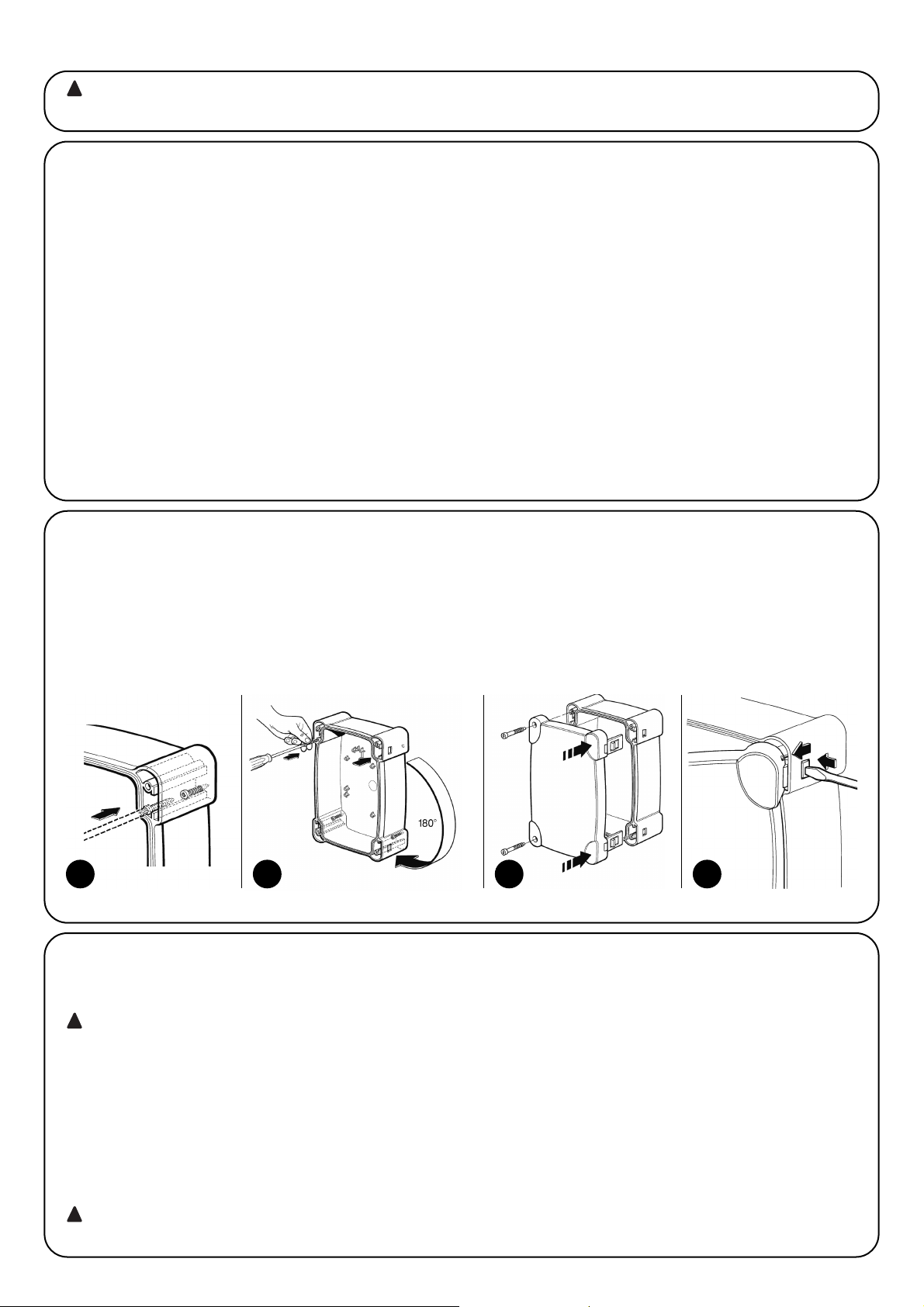
20
3.2) Fissaggio
Inserire le due viti negli appositi fori superiori facendole scorrere sulla guida, come fig. 3A avvitandole parzialmente. Ruotare di 180° la centrale e ripetere la stessa operazione con le altre 2 viti. Fissare a parete la centrale.
Inserire il coperchio dalla parte desiderata (con apertura a destra o sinistra), premere con forza in corrispondenza delle frecce.
Per togliere il coperchio premere con un cacciavite sul punto di incastro e contemporaneamente spingere verso l’alto.
L'installazione deve essere effettuata da personale qualificato, nel rispetto di leggi, norme e regolamenti e di quanto ripor-
tato nelle presenti istruzioni.
!
3) Installazione
3.1) Verifiche preliminari
Prima di procedere con l'installazione è necessario eseguire questi
controlli:
• Verificare che tutto il materiale da utilizzare sia in ottimo stato, adatto all'uso e conforme alle norme.
• Verificare che la struttura del cancello sia adatta ad essere automatizzata.
• Verificare che i punti di fissaggio dei vari dispositivi siano in zone
protette da urti e le superfici siano sufficientemente solide.
• Inserire appositi passacavi o passatubi solo nella parte inferiore
della centrale, per nessun motivo le pareti laterali e quella superiore devono essere forati. I cavi devono entrare nella centrale solo
dal lato inferiore!
• Evitare che le parti dell'automatismo possano venir immerse in
acqua o in altre sostanze liquide.
• Non porre A6 - A6F - A700F vicino a fiamme o fonti di calore; in
atmosfere potenzialmente esplosive, particolarmente acide o saline;
questo può danneggiare A6 - A6F - A700F ed essere causa di
malfunzionamenti o situazioni di pericolo.
• Nel caso sia presente una porta di passaggio interna all'anta oppure una porta sull'area di movimento dell'anta, occorre assicurarsi
che non intralci la normale corsa ed eventualmente provvedere
con un opportuno sistema di interblocco.
• Collegare la centrale ad una linea di alimentazione elettrica dotata
di messa a terra di sicurezza.
• La linea di alimentazione elettrica deve essere protetta da un adeguato dispositivo magnetotermico e differenziale.
• Sulla linea di alimentazione dalla rete elettrica è necessario inserire
un dispositivo di sconnessione dell'alimentazione (con categoria di
sovratensione III cioè distanza fa i contatti di almeno 3,5mm) oppure altro sistema equivalente ad esempio una presa e relativa spina.
Se il dispositivo di sconnessione dell'alimentazione non è in prossimità dell'automazione deve disporre di un sistema di blocco contro la connessione non intenzionale o non autorizzata.
3a 3b 3c 3d
3.3) Schema dei collegamenti
Installata quindi la centrale, gli attuatori, i relativi elementi di comando (selettore a chiave o pulsantiere) e di sicurezza (arresto di emergenza, fotocellule, costole sensibili e lampeggiante), è possibile passare ad eseguire i collegamenti elettrici seguendo le indicazioni riportate a seguito.
Per garantire l’incolumità dell’operatore e per prevenire danni ai componenti, mentre si effettuano i collegamenti, sia di bassa tensione
(230V - 120V) che di bassissima tensione (24V) o si innestano le varie schede:
La centrale non deve essere assolutamente alimentata elettricamente.
Ricordiamo inoltre che gli ingressi dei contatti di tipo NC (Normalmente Chiuso), se non usati, vanno ponticellati, se piú di uno vanno posti in
SERIE tra di loro; gli ingressi dei contatti di tipo NA (Normalmente Aperto) se non usati vanno lasciati liberi, se piú di uno vanno posti in PARALLELO tra di loro. Per quanto riguarda i contatti questi devono essere assolutamente di tipo meccanico e svincolati da qualsiasi potenziale,
non sono ammessi collegamenti a stadi tipo quelli definiti “PNP”, “NPN”, “Open Collector” ecc. ecc.
Effettuare i collegamenti necessari seguendo lo schema di Fig. 4 e la successiva descrizione dei collegamenti.
Si ricorda che vi sono delle normative precise da rispettare in modo rigoroso sia per quanto riguarda la sicurezza degli impianti elettrici
che per quanto riguarda i cancelli automatici.
!
!
Page 21

21
I
3.4) Descrizione dei collegamenti elettrici
Diamo una breve descrizione dei possibili collegamenti della centrale verso l’esterno:
1...3 : 230 - 120 Vac
4-5 : Lampeggiante = Uscita per collegamento al lampeggiante 230 - 120 Vac, potenza massima della lampada 100 W
6...8 : Motore 1 = Uscita per collegamento al 1° motore 230 - 120 Vac
9...11 : Motore 2 = Uscita per collegamento al 2° motore 230 - 120 Vac
Nota: I motori 1 e 2 di differenziano solo per il ritardo nelle partenza, il 1° motore è legato al tempo ritardo apertura “TRA” mentre il 2° motore è legato al tempo ritardo chiusura “TRC”. Se i ritardi non sono necessari non c’è alcuna differenza tra i due motori.
I seguenti morsetti sono presenti solo su
A6F e A700F
12-13 : Elettroserratura = Uscita 12 Vac per attivazione elettroserratura, potenza massima 25 W
La seguente serie di morsetti è presente solo sulla versione
A700F
14-15 : Fototest = Uscita 24 Vac per alimentazione trasmettitori delle fotocellule, massimo 100 mA
16 : Comune = Comune per gli ingressi finecorsa (uguale all’altro comune morsetto 23)
17 : Finecorsa C1 = Ingresso finecorsa chiude del motore 1
18 : Finecorsa A1 = Ingresso finecorsa apre del motore 1
19 : Finecorsa C2 = Ingresso finecorsa chiude del motore 2
20 : Finecorsa A2 = Ingresso finecorsa apre del motore 2
21-22 : 24 Vca = Uscita 24 Vca per alimentazione servizi (Foto, Radio ecc) massimo 200 mA
23 : Comune = Comune per tutti gli ingressi (come Comune è utilizzabile anche il morsetto 22)
24 : Spia C.A. = Uscita per spia cancello aperto 24 Vca , potenza massima della spia 2 W
25 : Alt = Ingresso con funzione di ALT (Emergenza, blocco o sicurezza estrema)
26 : Foto = Ingresso per dispositivi di sicurezza (Fotocellule, coste pneumatiche)
27 : Foto1 = Ingresso per altro dispositivo di sicurezza (Fotocellule, coste pneumatiche)
28 : Passo Passo = Ingresso per funzionamento ciclico (APRE STOP CHIUDE STOP)
La seguente serie di morsetti è presente solo sulla versione
A700F
29 : Apre = Ingresso per apertura (eventualmente comandata da un orologio)
30 : Chiude = Ingresso per chiusura
41-42 : 2° Ch Radio = Uscita dell’eventuale secondo canale del ricevitore radio
43-44 : Antenna = Ingresso per l’antenna del ricevitore radio
Sulla scheda della centrale sono presenti due connettori ad innesto previsti per schede opzionali:
RADIO = Innesto per ricevitori radio prodotti da Nice
PIU’ = Innesto per scheda espansioni PIU’ (solo sulla versione A700F)
E’ consigliabile attendere di aver completato l’installazione per inserire le eventuali schede opzionali RADIO o PIU’ e solo dopo aver verificato la funzionalità dell’impianto. Le schede opzionali non sono necessarie al funzionamento e se inserite rendono più difficile la ricerca di eventuali guasti.
La parte evidenziata è presente solo
sulla versione A700F
La parte evidenziata è presente sulle
versioni A6F e A700F
Antenna
4
2° Ch
Radio
FUNCTIONI 11-20FUNCTIONI 1-10
Fototest
24 Vac, Max 100 mA
230-120 Vac “L”
230-120 Vac “N”
Motore 1 Apre
Lampeggiante
230-120 Vac Max 100W
Motore 2 Apre
Motore 1 Chiude
Motore 1 Comune
Motore 2 Chiude
Motore 2 Comune
Elettroserratura
12 Vac, Max 25 W
Comune
Finecorsa Chiude 1
Finecorsa Apre 1
Finecorsa Chiude 2
Uscita 24 Vca (servizi)
Max 200 mA
Finecorsa Apre 2
Comune
Spia C.A.
Chiude
Apre
Passo Passo
Foto 1
Foto
Alt
Page 22

22
3.5) Note sui collegamenti
La maggior parte dei collegamenti è estremamente semplice, buona parte sono collegamenti diretti ad un singolo utilizzatore o contatto, alcuni invece prevedono una connessione un po’ più complessa:
Tutti i motori di tipo asincrono monofase richiedono un condensatore per il corretto funzionamento, alcuni motoriduttori, hanno già questo
condensatore collegato internamente, altri invece richiedono il collegamento del condensatore esternamente. In questo caso il condensatore va collegato fra le fasi APRE e CHIUDE del motore. Per praticità è opportuno inserire il condensatore direttamente dentro alla centrale negli
appositi spazi.
La seguente parte è relativa solo alla versione A700F
Una particolare descrizione merita venga rivolta all’uscita “Fototest”,
questa non è altro che la massima soluzione possibile in termini di
affidabilità nei confronti dei dispositivi di sicurezza. Ogni volta che
viene avviata una manovra vengono controllati i dispositivi di sicurezza coinvolti e solo se tutto è a posto la manovra ha inizio. Se invece il test non da esiti positivi (fotocellula accecata dal sole, cavi in
corto circuito ecc.) viene individuato il guasto e la manovra non viene eseguita.
Tutto questo è possibile solo impiegando una determinata configurazione nei collegamenti dei dispositivi di sicurezza (Fig. 5).
Come si può notare dallo schema elettrico, mentre i ricevitori delle
fotocellule FOTO, FOTO1 ed eventuale FOTO2 (su scheda PIU’)
sono alimentati normalmente dai 24 Vac dei servizi, i trasmettitori
prendono alimentazione dall’uscita fototest. Quando è richiesto un
movimento, in primo luogo viene controllato che tutti i ricevitori interessati dal movimento diano il consenso, poi, viene spenta l’uscita
fototest e quindi verificato che tutti i ricevitori segnalino il fatto
togliendo il loro consenso; infine viene riattivata l’uscita fototest e
quindi nuovamente verificato il consenso da parte di tutti i ricevitori.
Come si può notare sui due trasmettitori è stato attivato il sincronismo tagliando gli appositi ponticelli, questo è l’unico metodo per
garantire che le due coppie di fotocellule non si interferiscano tra
loro. Verificare sul manuale delle fotocellule le istruzioni per il funzionamento sincronizzato.
Nel caso un ingresso “FOTO” non venga usato, il relativo morsetto va ponticellato attraverso un relè 24 Vca collegato
sull’uscita fototest.
• Solitamente nei cancelli a 2 ante si impiegano motoriduttori che non richiedono l’uso dei finecorsa, è normale installare degli arresti meccanici che fermano il movimento nel punto desiderato. Nella centrale poi è presente il trimmer “Tempo Lavoro” che normalmente è regolato per un tempo poco superiore al tempo necessario per la completa manovra. Quando l’anta giunge sull’arresto meccanico il motore si
blocca e rimane sotto sforzo per il tempo residuo; i motori sono sempre progettati per resistere senza alcun problema a questo tipo di sollecitazione in particolare se la forza viene posta a valori inferiori al 100 %.
• In alcune installazioni, per esempio nel caso di due ante scorrevoli o nel caso si desideri sfruttare la funzione di posizionamento, potrebbe
essere richiesto l’uso dei finecorsa. Nella maggior parte dei casi, se vengono usati i finecorsa, sono di tipo normalmente chiuso “NC” in
modo che un eventuale guasto provoca la fermata del motore senza che l’anta possa andare ad incagliarsi. In altri casi, ad esempio quando si usano contatti di tipo magnetico, può capitare di dover usare finecorsa di tipo normalmente aperto “NA”.
Per abilitare la centrale all’uso dei finecorsa NA è necessario tagliare il ponticello FC presente sulla scheda (Fig 2). Questo stesso ponticello può essere tagliato anche nel caso i finecorsa non vengano utilizzati per evitare così di fare i relativi ponticelli.
• A seconda del tipo di motoriduttore e della funzione che si desidera ottenere i finecorsa possono essere impiegati come indicatore del punto di fine movimento ( funzione finecorsa ) oppure come segnalazione del punto di inizio della funzione posizionamento.
Se usati come posizionamento i finecorsa vanno di norma posti ad un angolo di 10-20° dal punto di arresto ed indicano il punto in cui ai
motori verrà applicata una forza ancora più bassa e regolabile con l’apposito trimmer FORZA POSIZIONAMENTO, in modo da raggiungere l’arresto meccanico con la minor violenza possibile.
5
Se il cancello è composto da 2 ante che si possono incagliare se in apertura partono contemporaneamente o se in chiusura una si sovrappone all’altra, allora è necessario intervenire sulle regolazioni dei trimmer Tempo Ritardo Apertura “TRA” o Tempo Ritardo Chiusura “TRC”.
Questi trimmer possono essere regolati a piacere anche se di norma TRA va regolato per lo stretto necessario a che l’anta mossa dal 2°
motore sia già fuori zona d’ingombro quando parte il 1° motore.
4) Regolazioni
TLM = Ponticello Tempo Lavoro Maggiorato
TL = Tempo Lavoro
TP = Tempo Pausa
TRA = Tempo Ritardo Apertura
TRC = Tempo Ritardo Chiusura
F = Forza
FP = Forza Posizionamento
Page 23

23
I
Il trimmer TRC deve essere regolato in modo che in chiusura l’anta
del 2° motore giunga sempre quando il 1° motore ha già terminato
la manovra di chiusura.
Il Tempo Ritardo Chiusura può essere impiegato per realizzare il franco di sicurezza di 50 cm in chiusura tra le ante.
A questo punto selezionare il modo di funzionamento “Semiautomatico” spostando in On il dip-switch N°1 quindi regolare il trimmer
Tempo Lavoro circa a metà corsa. Con queste regolazioni provare
un intero ciclo di apertura e poi uno di chiusura, eventualmente intervenire sulla regolazione del trimmer Tempo Lavoro in modo tale che
sia sufficiente ad eseguire tutta la manovra e rimanga ancora un
margine di tempo di 2 o 3 secondi. Nel caso anche ponendo al massimo il trimmer non si ottenga un tempo sufficiente e possibile tagliare il ponticello TLM posto sullo stampato vicino al trimmer ed ottenere così un tempo lavoro maggiorato.
In alcuni tipi di attuatori, ad esempio il tipo oleodinamico, la regolazione della forza è prevista direttamente sul gruppo attuatore, consultare il relativo manuale di istruzioni per chiarimenti sulla regolazione, quindi lasciare la regolazione di forza interna alla centrale impostata per il massimo. Per tutti quei tipi di attuatori che non contengono un dispositivo di regolazione di forza è invece possibile sfruttare il sistema di regolazione di forza interno alla centrale: in base alla
versione della centrale impiegata seguire le relative istruzioni.
La seguente parte è relativa solo alla versione A6
Sulla centrale è presente un trimmer FORZA che normalmente è
posto per la massima forza, con un cacciavite ruotare il trimmer in
senso antiorario fino a ridurre la forza del motore al valore previsto
dalle normative.
La seguente parte è relativa solo alle versioni A6F e A700F
Sulla centrale è presente un autotrasformatore di adeguata potenza
con delle prese intermedie sull’avvolgimento primario selezionabili
attraverso apposito commutatore FORZA, spostare il commutatore
sulla posizione più adatta al fine di ridurre la forza del motore al valore previsto dalle normative.
Qualunque sia il sistema di regolazione della forza per la fase iniziale
del movimento e per una durata di 1,5 Sec viene data il massimo
della forza, solo dopo questo tempo definito di “Spunto” viene inserita la forza prevista.
Se viene selezionato il modo di funzionamento in automatico (dipswitch N° 2 On) al termine della manovra di apertura viene eseguita
una “pausa” al termine della quale viene lanciata automaticamente
una manovra di chiusura. Questo tempo nel quale il cancello rimane
aperto è regolabile dall’apposito trimmer TEMPO PAUSA che può
essere impostato per il tempo preferito senza alcuna limitazione di
sorta. Una chiusura automatica e quindi la relativa pausa viene attivata anche nel movimento in semiautomatico quando, in chiusura,
l’intervento di un dispositivo di sicurezza provoca una inversione del
movimento in apertura.
Solo ora, al termine di tutte le regolazioni consigliamo di inserire l’eventuale ricevitore radio ricordando che i comandi da esso provenienti vengono inviati all’ingresso PASSO-PASSO.
4.1) Modi di funzionamento
Nota: alcune delle parti descritte a seguito sono relative solo alla
versione A700F
Nel funzionamento in modo manuale, l’ingresso APRE consente il
movimento in apertura, l’ingresso CHIUDE consente il movimento in
chiusura. il PASSO P. consente il movimento alternativamente in
apertura e in chiusura; non appena cessa il comando in ingresso il
movimento si arresta. In apertura il movimento si arresta quando
intervengono i finecorsa oppure se manca il consenso dalla FOTO2
(su scheda PIU); in chiusura invece il movimento si arresta anche se
manca il consenso di FOTO e FOTO1. Sia in apertura che in chiusura un intervento su ALT provoca sempre un immediato arresto del
movimento e una breve inversione. Una volta che un movimento si è
arrestato è necessario far cessare il comando in ingresso prima che
un nuovo comando possa far iniziare un nuovo movimento.
Nel funzionamento in uno dei modi automatici (semiautomatico,
automatico o chiude sempre) un impulso di comando sull’ingresso
APRE provoca il movimento in apertura, se il comando permane una
volta raggiunta l’apertura il movimento rimane “congelato” in una
pausa infinita; solo quando cessa il comando il cancello si potrà
essere richiuso.
Un impulso su PASSO PASSO provoca alternativamente apertura o
chiusura. Un secondo impulso sul PASSO P. o sullo stesso ingresso
che ha iniziato il movimento provoca uno Stop.
Sia in apertura che in chiusura un intervento su ALT provoca un
immediato arresto del movimento e una breve inversione.
Se in un ingresso di comando invece di un impulso viene mantenuto un segnale continuo si provoca uno stato di “prevalenza” in cui gli
altri ingressi di comando rimangono disabilitati (utile per collegare un
orologio o un selettore Notte-Giorno).
Nel caso fosse selezionato il modo di funzionamento automatico,
dopo una manovra di apertura, viene eseguita una pausa al termine
viene eseguita una chiusura. Se durante la pausa vi fosse un intervento di FOTO o FOTO1, il temporizzatore verrà ripristinato con un
nuovo tempo pausa; se invece durante la pausa si interviene su ALT
la funzione di richiusura viene cancellata e si passa in uno stato di
STOP. In apertura gli interventi di FOTO o FOTO1 non hanno alcun
effetto mentre la FOTO2 (su scheda PIU) provoca l’inversione del
moto; in chiusura l’intervento di FOTO o FOTO1 provoca una inversione del moto poi una pausa quindi una richiusura.
La centrale dispone di una serie di microinterrutori che permettono
di attivare varie funzioni al fine di rendere l’impianto più adatto alle
esigenze dell’utilizzatore e più sicuro nelle varie condizioni d’uso. Tutte le funzioni sono attivate ponendo il relativo dip-switch in posizione “On” mentre non sono inserite con il corrispondente dip-switch in
“Off”; alcune funzioni non hanno una immediata efficacia ed hanno
senso solo in determinate condizioni, ad esempio la funzione N° 12
“Lampeggiante anche in pausa” è attiva solo con la chiusura automatica e se la manovra non viene interrotta con un comando di ALT.
ATTENZIONE alcune delle funzioni programmabili solo legati ad
aspetti della sicurezza, valutare con molta attenzione gli effetti di una
funzione e verificare quale sia la funzione che dia la maggior sicurezza possibile.
Nella manutenzione di un impianto prima di modificare una funzione
programmabile valutare il motivo per cui nella fase di installazione
erano state fatte determinate scelte, quindi verificare se con la nuova programmazione la sicurezza ne risente.
!
5) Programmazioni
Page 24

24
5.1) Funzioni programmabili
Il dip-switch FUNZIONI permette di selezionare i vari modi di funzionamento e di inserire le funzioni desiderate secondo la seguente tabella:
Switch 1-2: Off Off = Movimento “Manuale” cioè Uomo Presente
On Off = Movimento “Semiautomatico”
Off On = Movimento “Automatico” cioè Chiusura Automatica
On On = Movimento “Automatico + Chiude Sempre”
Switch 3 On = Funzionamento Condominiale < Non disponibile in modo Manuale>
Switch 4 On = Prelampeggio
Switch 5 On = Richiudi subito dopo Foto < solo in modo Automatico >
Switch 6 On = Foto1 anche in apertura
Switch 7 On = Partenza graduale
Switch 8 On = Fermata graduale
Switch 9 On = Colpo d’ariete
Switch 10 On = Luce di cortesia su lampeggiante
Nella versione
A700F è presente un secondo gruppo di dip-switch con altre funzioni:
Switch 11 On = Funzione posizionamento < solo con l’utilizzo dei finecorsa >
Switch 12 On = Lampeggiante anche in Pausa < solo in modo Automatico >
Switch 13 On = Mantenimento pressione
Switch 14 On = Spia C.A. con lampeggio proporzionale
Switch 15 On = Attivazione Fototest
Switch 16 On = Foto e Foto1 anche in apertura
Switch 17 On = Foto e Foto1 ad inizio manovra di apertura
Switch 18 On = Salta STOP in apre
Switch 19 On = Salta STOP in chiude
Switch 20 On = CHIUDE diventa APRE PEDONALE
Ricordiamo che le funzioni che sono possibili solo in determinati casi sono segnalate con le note tra i caratteri “<>” dopo la
descrizione della funzione.
Naturalmente ogni dip-switch posto in “Off” non attiva la funzione descritta.
5.2) Descrizione delle funzioni
Riportiamo ora una breve descrizione delle funzioni che si possono
inserire portando in “On” il relativo dip-switch
Switch 1-2: Off Off = Movimento “Manuale” (Uomo Presente)
On Off = Movimento “Semiautomatico”
Off On = Movimento “Automatico”
(Chiusura Automatica)
On On = Movimento “Automatico + Chiude
Sempre”
Nel funzionamento “Manuale” il movimento viene eseguito solo fino
alla presenza del comando (tasto premuto).
In “Semiautomatico” basta un impulso di comando e viene eseguito
tutto il movimento fino al raggiungimento dell’arresto meccanico o
fino all’intervento del finecorsa. Nel funzionamento in modo “Automatico” dopo una apertura viene eseguita una pausa e quindi una
chiusura. La funzione “Chiude Sempre” interviene dopo una mancanza momentanea di alimentazione; se viene rilevato il cancello
aperto si avvia automaticamente una manovra di chiusura preceduta da 5 secondi di prelampeggio.
Switch 3: On = Funzionamento Condominiale (non disponibile in
modo Manuale)
Nel funzionamento condominiale, una volta avviato un movimento in
apertura la manovra non puó piú essere interrotta da altri impulsi di
comando su PASSO PASSO o APRE fino alla fine del movimento in
apertura. Nel movimento in chiusura un nuovo impulso di comando
provoca l’arresto e l’inversione del movimento in apertura.
Switch 4: On = Prelampeggio
All’impulso di comando viene prima attivato il lampeggiante poi dopo
5 secondi (2 Sec. se in manuale) inizia il movimento.
Switch 5: On = Richiudi subito dopo Foto (solo se in modo Automatico)
Questa funzione permette di tenere il cancello aperto solo per il tempo necessario al transito, infatti dopo l’intervento di FOTO o FOTO1
la chiusura avverrà sempre con una pausa di 5 secondi indipendentemente dal Tempo Pausa regolato.
Switch 6: On = Foto1 anche in apertura
Questa funzione è l’unica che diversifica il funzionamento tra le fotocellule FOTO e FOTO1. Normalmente le sicurezze FOTO e FOTO1
intervengono solo nella manovra di chiusura mentre in apertura non
hanno alcun effetto.
Se il dip-switch N° 6 viene posto “On” FOTO continua ad intervenire solo in chiusura ma FOTO1 interviene anche in apertura provocando una interruzione del movimento. In semiautomatico od automatico la ripresa del moto avverrà quando FOTO1 verrà nuovamente disimpegnata. Questo tipo di funzionamento ritorna utile per arrestare il moto del cancello in apertura, quando, per esempio un veicolo si avvicina al cancello dal lato interno e quindi nella direzione del
movimento, senza nello stesso tempo fermare il movimento quando
il veicolo si avvicina dal lato esterno.
Switch 7: On = Partenza graduale
L’inizio del movimento viene eseguito in modo graduale inviando una
forza sempre maggiore al motore formando una rampa che dura di
circa 1 Sec, questo garantisce che la partenza avvenga senza scossoni. (Funzione sconsigliata su motoriduttori METRO).
Switch 8: On = Fermata graduale
Quando il movimento termina viene eseguita una fermata in modo
graduale inviando una forza sempre minore al motore con un decremento che dura circa 1 Sec, questo garantisce che la fermata
avvenga senza scossoni.
Page 25

25
I
Per ovvi motivi di sicurezza la fermata graduale non avviene, e viene
sostituita da una fermata normale, quando interviene ALT, FOTO e
FOTO1o FOTO2 (su scheda PIU’) oppure uno dei finecorsa.
Switch 9: On = Colpo d’ariete
Quando si impiegano attuatori reversibili, quindi il cancello non rimane chiuso con la sola spinta dei motori, diventa indispensabile installare una elettroserratura (vedere le istruzioni degli attuatori per le
modalità d’uso).
Sull’elettroserratura si potrebbe così trovare applicata quella naturale spinta che tende a portare le ante in posizione leggermente aperta, talvolta questa spinta è così elevata da mantenere bloccato il
meccanismo di scatto dell’elettroserratura.
Con la funzione colpo d’ariete inserita, prima di iniziare una manovra
di apertura viene attivato un breve ciclo di chiude, che comunque
non crea alcun effetto di movimento visto che le ante sono già sull’arresto meccanico di chiusura. In questo modo quando l’elettroserratura viene attivata si troverà scarica da qualsiasi forza e quindi
libera di scattare.
Switch 10: On = Luce di cortesia su lampeggiante
In determinati casi può essere richiesto una illuminazione sulla zona
di movimento del cancello e spesso si richiede che l’illuminazione si
spenga automaticamente poco dopo che il cancello ha concluso la
manovra. Questa funzione viene comunemente definita “Luce di cortesia”. Collegando degli appropriati corpi illuminanti sulla stessa uscita del lampeggiate (per una potenza massima complessiva di 100 W)
ed attivando questa funzione si otterrà che durante tutto il movimento e per altri 60 Sec. l’uscita rimarrà attiva permettendo l’illuminazione della zona.
Solo nella versione
A700F è presente un secondo gruppo di dipswitch con altre funzioni:
Switch 11: On = Funzione posizionamento (solo con l’utilizzo dei
finecorsa)
I finecorsa possono essere impiegati, invece che come segnalazione dei limiti del movimento, come indicazione del punto in cui scatta il posizionamento. Di norma quando si usa la funzione posizionamento i finecorsa vengono posti ad un angolo di 10-20° prima dell’arresto meccanico. In questo modo quando nel movimento dell’anta si raggiunge il finecorsa al motore verrà inviata una forza minore, regolabile con l’apposito trimmer “Forza Posizionamento”, per un
tempo di altri 3 Sec. in modo che l’anta raggiunga l’arresto meccanico con la minor violenza possibile.
Switch 12: On = Lampeggiante anche in Pausa
Normalmente il lampeggiante viene attivato solo durante il movimento in apertura o chiusura, questa funzione prevede che il lampeggiante rimanga attivo anche durante la Pausa allo scopo di segnalare lo stato di “prossima chiusura”.
Switch 13: On = Mantenimento pressione
Negli attuatori oleodinamici la spinta per mantenere chiuso il cancello è sviluppata in un circuito idraulico che rimane sempre sotto pressione. Quando il tempo e l’usura riducono la tenuta del circuito
idraulico può capitare che dopo qualche ora la pressione interna
decada con conseguente rischio di leggera apertura delle ante del
cancello. Se si inserisce la funzione Mantenimento Pressione, dopo
4 ore, poi ogni 4 ore che il cancello è chiuso viene attivata una breve manovra di chiude con il solo scopo di ricaricare la pressione del
circuito idraulico.
NOTA: Le funzioni “Colpo d’ariete” e “Mantenimento pressione” hanno senso e vengono eseguite solo se il cancello è chiuso. La logica
interna considera cancello chiuso se c’è il relativo finecorsa FCC
intervenuto o, nel caso i finecorsa non siano usati, dal fatto che la
precedente manovra di chiusura è terminata regolarmente per fine
del tempo lavoro.
Switch 14: On = Spia C.A. con lampeggio proporzionale
Normalmente la Spia Cancello Aperto indica lo stato del cancello
secondo i seguenti stati:
Spenta: Cancello completamente chiuso
Accesa: Cancello anche solo parzialmente aperto
Lampeggio lento: Cancello in fase di apertura
Lampeggio veloce: Cancello in fase di chiusura
Il lampeggio della spia durante il movimento può essere reso proporzionale, da lento, progressivamente a veloce e viceversa in modo
di avere un’indicazione dello stato di apertura o chiusura.
Switch 15: On = Attivazione Fototest
Permette di avviare una fase di test sulle fotocellule prima di iniziare
ogni movimento, in questo modo eliminando ogni possibilità di malfunzionamento si aumenta la sicurezza dell’impianto. Per sfruttare la
funzione Fototest è necessario che i trasmettitori delle fotocellule siano collegati all’apposita uscita (vedere: Note dei collegamenti).
Switch 16: On = Foto e Foto1 anche in apertura
Normalmente le sicurezze FOTO e FOTO1 intervengono solo nella
manovra di chiusura, se il dip-switch N° 16 viene attivato l’intervento dei dispositivi di sicurezza provocano una interruzione del movimento anche in apertura, se in Semiautomatico od Automatico si
avrà la ripresa nuovamente del moto in apertura subito dopo il disimpegno.
Switch 17: On = Foto e Foto1 ad inizio manovra di apertura
Solitamente i dispositivi di sicurezza FOTO e FOTO1 non sono attivi
nella manovra di apre ma solo nella manovra di chiude perchè la più
pericolosa. In alcune nazioni vi sono delle normative che impongono
il controllo dei dispositivi di sicurezza almeno all’inizio anche della
manovra di apre. Se è necessario rispettare queste norme o si desidera aumentare il livello di sicurezza e possibile attivare la funzione e
quindi prima di iniziare il movimento, verificare il consenso dalle sicurezze FOTO e FOTO1 e solo dopo iniziare il movimento.
Switch 18: On = Salta STOP in apre
Il ciclo del Passo Passo è normalmente: APRE-STOP-CHIUDESTOP, con questa funzione inserita il ciclo Passo Passo diventa:
APRE-CHIUDE-STOP-APRE, mentre l’ingresso Apre perde la possibilità di fare STOP
Switch 19: On = Salta STOP in chiude
E’ come la funzione precedente ma relativa al ciclo chiude, quindi il
ciclo Passo Passo diventa: APRE-STOP-CHIUDE -APRE, mentre
l’ingresso Chiude perde la possibilità di fare STOP
NOTA: Ponendo On i dip-switch 18 e 19 il ciclo passo passo diventa APRE-CHIUDE-APRE perdendo definitivamente la possibilità di
fare STOP.
Switch 20: On = CHIUDE diventa APRE PEDONALE
Può capitare che non sia necessario aprire completamente il cancello ad esempio quando deve transitare un pedone in questo caso
diventa utile la funzione di APRE PEDONALE che permette di aprire
solo l’anta collegata al 2° motore lasciando l’altra chiusa.
Questo tipo di apertura viene attivata dall’ingresso CHIUDE che perde la sua funzione originale per diventare come l’ingresso PassoPasso ma per l’apertura di una sola anta. E’ da precisare che il ciclo
di apre pedonale si attiva solo partendo da cancello chiuso se invece il cancello è in movimento o comunque aperto l’impulso di ingresso non ha alcun effetto.
ACCESSORIO: SCHEDA ESPANSIONI “PIÙ“
La centrale elettronica dispone di tutte le principali funzioni richieste
in una normale automazione, nella versione A700F è stata prevista la
possibilità di aggiungere la scheda opzionale PIU’ che permette di
aumentare le prestazione della centrale.
Page 26
26
La seguente parte è relativa solo alla versione A700F
La scheda va innestata nell’apposito connettore sulla centrale, quindi sui morsetti della scheda sono disponibili:
• I seguenti ingressi: Foto 2 = Dispositivo di sicurezza con intervento nella manovra di apertura
Apre Parziale = Esegue una manovra di apertura con un tempo ridotto
• Le seguenti uscite: Rosso = Luce rossa del semaforo
Verde = Luce verde del semaforo
Allarmi
Elettroserratura = Comando dell’elettroserratura (visto che la centrale dispone già di questa uscita la
funzione è stata modificata in “Ventosa” per collegare quei dispositivi di ritenuta
magnetica che si usano in alternativa all’elettroserratura)
Luce di Cortesia = Comando di una lampada con funzione di luce di cortesia
Nota: Le uscite possono comandare solo carichi di piccola potenza (lampade spia, relè ecc.)
• e le seguenti regolazioni: Tempo Parziale = Tempo per l’apertura parziale
Tempo Cortesia = Tempo per la luce di cortesia
Le caratteristiche complete e la modalità d’uso della scheda sono riportate nel relativo manuale di istruzioni.
Terminati i collegamenti dei motori e dei vari accessori previsti è possibile passare alla verifica di tutti i collegamenti ed al collaudo dell’impianto.
Questa è la fase più importante nella realizzazione dell'automazione al fine di garantire la massima sicurezza. Il collaudo può essere usato anche come verifica periodica dei dispositivi che compongono l'automatismo.
Il collaudo dell'intero impianto deve essere eseguito da personale
esperto e qualificato che deve farsi carico delle prove richieste, in
funzione del rischio presente e di verificare il rispetto di quanto previsto da leggi, normative e regolamenti, ed in particolare tutti i requisiti della norma EN12445 che stabilisce i metodi di prova per la verifica degli automatismi per cancelli.
Si consiglia di operare in modo manuale con tutte le funzioni disattivate (dip-switch Off); per ogni eventualità, in modo manuale, rilasciando il tasto di comando si ottiene l’immediato arresto del motore. Verificare anche che tutti i trimmer di regolazione siano al minimo
(ruotati in senso antiorario) solo il trimmer FORZA (su A6) o il commutatore FORZA (su A6F e A700F) può essere posto al massimo,
il trimmer Forza Posizionamento (su A700F) va posto a metà corsa.
Ogni singolo componente dell'automatismo, ad esempio bordi sensibili, fotocellule, arresto di emergenza, ecc. richiede una specifica
fase di collaudo; per questi dispositivi si dovranno eseguire le procedure riportate nei rispettivi manuali istruzioni.
Verificare che sia stato rispettato rigorosamente tutto quanto previsto
nel presente manuale ed in particolare nel capitolo “1 Avvertenze”;
A) Sbloccare il cancello e portare le ante a metà della corsa poi bloc-
care, in questo modo il cancello è libero di muoversi sia in apertura che in chiusura.
B) Alimentare la centrale, verificare che tra morsetti 1-2 e 1-3 vi sia-
no 230Vac / 120Vac e che sui morsetti 21-22 vi siano 24 Vca.
La seguente parte è relativa solo alla versione
A700F
C) Verificare che sui morsetti 14-15 sia presente una tensione di 24
Vac per alimentazione trasmettitori delle fotocellule.
Non appena la centrale è alimentata le spie luminose (LED) che sono
poste sugli ingressi attivi devono illuminarsi, inoltre dopo pochi istanti il led “OK” dovrà iniziare a lampeggiare con cadenza regolare. Se
tutto questo non avviene, togliere immediatamente alimentazione e
controllare con maggior attenzione i collegamenti.
• Il led “OK” posizionato al centro della scheda, ha il compito di
segnalare lo stato della logica interna: un lampeggio regolare ed
alla cadenza di 1 secondo indica che il microprocessore interno
è attivo ed è in attesa di comandi. Quando invece lo stesso
microprocessore riconosce una variazione dello stato di un
ingresso (sia ingresso di comando che dip-switch delle funzioni)
genera un doppio lampeggio veloce, questo anche se la variazione non provoca effetti immediati. Un lampeggio molto veloce per
3 secondi indica che la centrale è appena stata alimentata e sta
eseguendo un test delle parti interne, infine un lampeggio irregolare e non costante indica che il test non è andato a buon fine e
quindi c’è un guasto.
D) Ora verificare che i led relativi agli ingressi con contatti tipo NC
siano accesi (tutte le sicurezze attive) e che i led relativi ad ingressi tipo NA siano spenti (nessun comando presente), se questo
non avviene controllare i collegamenti e l’efficienza dei vari dispositivi.
E) Verificare il corretto funzionamento di tutti i dispositivi di sicurezza
presenti nell’impianto (arresto di emergenza, fotocellule, coste
pneumatiche ecc.), ogni volta che intervengono, il relativi led ALT,
FOTO o FOTO1 devono spegnersi.
• Questa è una verifica fra le più importanti e deve essere eseguita
con la massima attenzione, dal corretto funzionamento dei dispositivi di sicurezza dipende tutta la sicurezza “attiva” della macchina cancello. Se il lampeggiante è un ottimo strumento per segnalare lo stato di pericolo ed i limitatori di coppia sono un valido
ausilio per limitare i danni, solo una corretta installazione dei
dispositivi di sicurezza permette di bloccare l’automatismo prima
che possa provocare danni.
La seguente parte è relativa solo alla versione
A700F
F) Se vengono utilizzati gli ingressi finecorsa bisogna verificare l’e-
sattezza dei collegamenti. Muovere le ante una alla volta e verificare che una volta raggiunto il punto desiderato il relativo finecorsa intervenga spegnendo il corrispondente led sulla centrale (o
accendendolo se sono montati dei finecorsa NA).
• Ora bisognerà verificare se il movimento avviene nella direzione
corretta cioè controllare la corrispondenza tra il movimento previsto dalla centrale e quello effettivo delle ante. Questa verifica è
fondamentale, se la direzione è sbagliata in alcuni casi (ad esempio in modo semiautomatico) il cancello potrebbe in apparenza
funzionare regolarmente infatti il ciclo APRE è simile al ciclo CHIUDE con la fondamentale differenza che i dispositivi di sicurezza
verranno ignorati nella manovra di chiude, che normalmente è la
più pericolosa, ed interverranno in apertura provocando una
richiusura addosso all’ostacolo con effetti disastrosi!
!
6) Collaudo
}
Page 27
27
I
G) Per verificare se il senso di rotazione è esatto basta dare un bre-
ve impulso sull’ingresso Passo-Passo; la prima manovra che la
centrale esegue dopo che è stata alimentata è sempre APRE,
quindi è sufficiente verificare se il cancello si muove nel senso dell’apertura; infine nel caso il movimento sia avvenuto i senso errato occorre:
1 - Spegnere alimentazione
2 - Scambiare i collegamenti “APRE” e “CHIUDE” del motore o
dei motori che ruotavano in senso contrario.
Eseguito quanto descritto conviene riprovare se il senso di rotazione
è corretto ripetendo l’operazione del punto “G”.
H) Verificati tutti i collegamenti ed eseguita la verifica del senso di
rotazione dei motori è possibile provare un movimento completo
degli attuatori, si consiglia di operare sempre in modo manuale
con tutte le funzioni disattivate. Se si usa come comando l’in-
gresso Passo Passo il primo movimento (dopo l’accensione)
dovrà essere in apertura. Agendo sugli ingressi di comando movi-
mentare il cancello fino al punto di apertura, se tutto si è svolto
regolarmente è possibile passare al movimento in senso di chiu-
sura e muovere il cancello fino al relativo punto di arresto.
Conviene eseguire diverse manovre apre-chiude al fine di valutare
eventuali difetti nella struttura meccanica dell’automazione e di rilevare la presenza di particolari punti di attrito.
I) Passare ora a provare l’intervento dei dispositivi di sicurezza,
FOTO e FOTO1 nella manovra di apertura non hanno alcun effetto, in chiusura provocano la fermata del movimento. Se presente
la scheda PIU’ provare anche il funzionamento dell’ingresso
FOTO 2, in chiusura non ha alcun effetto, in apertura provoca la
fermata del movimento. I dispositivi collegati nell’ingresso ALT
agiscono sia in apertura che in chiusura provocando sempre la
fermata del movimento.
L) Se le situazioni pericolose provocate dal movimento delle ante
sono state salvaguardate mediante la limitazione della forza d'impatto si deve eseguire la misura della forza secondo quanto previsto dalla norma EN 12445. Se il controllo della “Forza Motore”
vengono usati come ausilio al sistema per la riduzione della forza
d'impatto, provare e trovare le regolazioni che offrono i migliori
risultati.
6.1) Messa in servizio
La messa in servizio può avvenire solo dopo aver eseguito con esito positivo tutte le fasi di collaudo della centrale e degli altri dispositivi presenti.
E' vietata la messa in servizio parziale o in situazioni “provvisorie”.
1. Realizzare e conservare per almeno 10 anni il fascicolo tecnico
dell'automazione che dovrà comprendere almeno: disegno complessivo dell'automazione, schema dei collegamenti elettrici, analisi
dei rischi e relative soluzioni adottate, dichiarazione di conformità del
fabbricante di tutti i dispositivi utilizzati (per A6 - A6F - A700F uti-
lizzare la Dichiarazione CE di conformità allegata); copia del manuale di istruzioni per l'uso e del piano di manutenzione dell'automazione.
2. Apporre sul cancello una targhetta contenente almeno i seguenti
dati: tipo di automazione, nome e indirizzo del costruttore (responsabile della “messa in servizio”), numero di matricola, anno di costruzione e marchio “CE”.
3. Fissare in maniera permanente in prossimità del cancello un'etichetta o una targa con indicate le operazioni per lo sblocco e la
manovra manuale.
4. Realizzare e consegnare al proprietario la dichiarazione di conformità dell'automazione.
5. Realizzare e consegnare al proprietario il manuale di “Istruzioni ed
avvertenze per l'uso dell'automazione”.
6. Realizzare e consegnare al proprietario il piano di manutenzione
dell'automazione (che deve raccogliere tutte le prescrizioni sulla
manutenzione dei singoli dispositivi installati).
7. Prima di mettere in servizio l'automatismo informare adeguatamente ed in forma scritta il proprietario (ad esempio sul manuale di
istruzioni ed avvertenze per l'uso dell'automazione) sui pericoli ed i
rischi residui ancora presenti.
7.1) Manutenzione
Per mantenere costante il livello di sicurezza e per garantire la massima durata dell'intera automazione è necessaria una manutenzione
regolare.
La manutenzione deve essere effettuata nel pieno rispetto delle prescrizioni sulla sicurezza del presente manuale
e secondo quanto previsto dalle leggi e normative vigenti.
Per gli altri dispositivi diversi da A6 – A6F – A700F seguire quanto
previsto nei rispettivi piani manutenzione.
1. E’ necessaria una manutenzione programmata al massimo entro
6 mesi o al massimo dopo 10.000 manovre dalla precedente manutenzione.
2. Scollegare qualsiasi sorgente di alimentazione elettrica.
3. Verificare lo stato di deterioramento di tutti i materiali che com-
pongono l'automazione con particolare attenzione a fenomeni di
erosione o di ossidazione delle parti strutturali; sostituire le parti che
non forniscono sufficienti garanzie.
4. Ricollegare le sorgenti di alimentazione elettrica ed eseguire tutte
le prove e le verifiche previste nel paragrafo “ 6 Collaudo”.
In questo capitolo sono riportate le informazioni per la realizzazione del piano di manutenzione e lo smaltimento di A6 - A6F
- A700F
!
7) Manutenzione e smaltimento
Page 28

28
7.2) Smaltimento
Come per l'installazione, anche al termine della vita di questo prodotto, le operazioni di smantellamento devono essere eseguite da
personale qualificato.
Questo prodotto è costituito da vari tipi di materiali, alcuni possono
essere riciclati altri devono essere smaltiti; informatevi sui sistemi di
riciclaggio o smaltimento previsti dai regolamenti locali per questa
categoria di prodotto.
Alcune parti del prodotto possono contenere sostanze
inquinanti o pericolose, se disperse potrebbero provocare
effetti dannosi sull'ambiente e sulla salute umana.
Come indicato dal simbolo di figura è vietato gettare questo prodotto nei rifiuti
domestici. Eseguire la "raccolta separata" per lo smaltimento secondo i metodi
previsti dai regolamenti locali; oppure
riconsegnare il prodotto al venditore nel
momento dell'acquisto di un nuovo pro
dotto equivalente.
Regolamenti locali possono prevedere pesanti sanzioni in caso di
smaltimento abusivo di questo prodotto.
!
Per A6 – A6F – A700F sono previsti i seguenti accessori opzionali:
SCHEDA “PIU”
La centrale contiene già tutte le funzioni che vengono utilizzati in una normale installazione, ma per sopperire alle richieste di utilizzo in impianti particolari, è stata predisposta una scheda opzionale “Scheda PIU” che permette di aggiungere nuove funzione quali segnalazione semaforica, luce di cortesia, ventosa, Foto2, apertura parziale delle 2 ante.
SCHEDA “RADIO”
Nelle centrale è predisposto un connettore ad innesto Nice per l’inserimento di una scheda radio che permette di agire sull’ingresso di PASSO-PASSO e comandare in questo modo la centrale a distanza tramite un trasmettitore.
Consultare il catalogo prodotti di Nice S.p.a. per l'elenco completo ed aggiornato degli accessori.
8) Accessori
Con lo scopo di migliorare i propri prodotti, Nice S.p.a si riserva il diritto di modificare le caratteristiche tecniche in qualsiasi momento e senza preavviso pur mantenendo funzionalità e destinazione d'uso.
Tutte le caratteristiche tecniche riportate si riferiscono alla temperatura ambientale di 20°C (±5°C).
9) Caratteristiche tecniche
Modello: A6 -A6/V1 A6F -A6F/V1 A700F –A700F/V1
Alimentazione A6 – A6F – A700F 230 Vac ± 10%, 50 - 60 Hz
Alimentazione A6/V1 – A6F/V1 - A700F/V1 120 Vac ± 10%, 50 - 60 Hz
Potenza massima attuatori 230 Vac 300 W [1,3 A]
Potenza massima attuatori / V1 120 Vac 300 W [2,5 A]
Potenza massima lampeggiante 100W
N° massimo cicli ora illimitato
N° massimo cicli consecutivi illimitato
Corrente massima servizi (24 Vac) 200 mA
Corrente massima uscita fototest (24 Vac) / / 100 mA
Potenza massima spia SCA (24Vac) 2 W
Potenza massima elettroserratura (12 Vac) / 15 VA 15 VA
Tempo lavoro da 2,5 a 40 sec. (da 30 a 80 sec. con TLM)
Tempo pausa da 5 a 80 sec.
Tempo ritardo apertura TRA 0 oppure da 2.5 a 12 sec.
Tempo ritardo chiusura TRC 0 oppure da 2.5 a 12 sec.
Regolazione forza da 0 al 100 % 30%-45%-60%-80%-100%
Temperatura di funzionamento -20 ÷ 50 °C
Dimensioni 280 x 220 x 110 mm
Peso 1,7 Kg 2,7 Kg 2,7 Kg
Grado di protezione IP 55 (con contenitore integro)
Page 29

29
I
Complimenti per aver scelto per la vostra automazione un pro-
dotto Nice! Nice S.p.a. produce componenti per l'automazione di
cancelli, porte,serrande, tapparelle e tende da sole: motoriduttori,
centrali di comando,radiocomandi, lampeggianti, fotocellule e
accessori. Nice utilizza solo materiali e lavorazioni di qualità, e per
vocazione ricerca soluzioni innovative che semplifichino al massimo l'utilizzo delle sue apparecchiature, curate nelle soluzioni tecniche, estetiche, ergonomiche: nella grande gamma Nice il vostro
installatore avrà senz'altro scelto il prodotto più adatto alle vostre
esigenze. Nice non è però il produttore della vostra automazione,
che è invece il risultato di un'opera di analisi, valutazione, scelta
dei materiali, e realizzazione dell'impianto eseguita dal vostro
installatore di fiducia. Ogni automazione è unica e solo il vostro
installatore possiede l'esperienza e la professionalità necessarie
ad eseguire un impianto secondo le vostre esigenze, sicuro ed
affidabile nel tempo, e soprattutto a regola d'arte, rispondente
cioè alle normative in vigore. Un impianto di automazione è una
bella comodità, oltre che un valido sistema di sicurezza e, con
poche, semplici attenzioni, è destinato a durare negli anni. Anche
se l'automazione in vostro possesso soddisfa il livello di sicurezza
richiesto dalle normative, questo non esclude l'esistenza di un
“rischio residuo”, cioè la possibilità che si possano generare situazioni di pericolo, solitamente dovute ad un utilizzo incosciente o
addirittura errato, per questo motivo desideriamo darvi alcuni consigli sui comportamenti da seguire per evitare ogni inconveniente:
• Prima di usare per la prima volta l’automazione, fatevi
spiegare dall’installatore l’origine dei rischi residui, e dedicate
qualche minuto alla lettura del manuale di istruzioni ed avver-
tenze per l’utilizzatore consegnatovi dall’installatore. Conservate il manuale per ogni dubbio futuro e consegnatelo ad un
eventuale nuovo proprietario dell’automazione.
• La vostra automazione è un macchinario che esegue
fedelmente i vostri comandi; un uso incosciente ed improprio può farlo diventare pericoloso: non comandate il movimento dell’automazione se nel suo raggio di azione si trovano persone, animali o cose.
• Bambini: un impianto di automazione garantisce un alto grado
di sicurezza, impedendo con i suoi sistemi di rilevazione il movimento in presenza di persone o cose, e garantendo un’attivazione sempre prevedibile e sicura. È comunque prudente vietare ai bambini di giocare in prossimità dell’automazione e per evitare attivazioni involontarie non lasciare i telecomandi alla loro
portata: non è un gioco!
• Le fotocellule non sono un dispositivo di sicurezza ma
soltanto un dispositivo ausiliario alla sicurezza. Sono costruite
con tecnologia ad altissima affidabilità ma possono, in situazioni
estreme, subire malfunzionamenti o addirittura guastarsi ed in
certi casi il guasto potrebbe non essere subito evidente.
Per questi motivi, e comunque per buona regola:
- Il transito è consentito solo se il cancello o portone è completa-
mente aperto e con ante ferme.
- E' ASSOLUTAMENTE VIETATO transitare mentre il cancello
o portone si sta chiudendo!
Verificare periodicamente il corretto funzionamento delle fotocellule e
far eseguire i controlli di manutenzione previsti, almeno ogni 6 mesi.
• Anomalie: Non appena notate qualunque comportamento
anomalo da parte dell’automazione, togliete alimentazione elettrica all’impianto ed eseguite lo sblocco manuale. Non tentate da
soli alcuna riparazione, ma richiedete l’intervento del vostro
installatore di fiducia: nel frattempo l’impianto può funzionare
come un’apertura non automatizzata, una volta sbloccato il
motoriduttore come descritto più avanti.
• Manutenzione: Come ogni macchinario la vostra automazione
ha bisogno di una manutenzione periodica affinché possa funzionare più a lungo possibile ed in completa sicurezza. Concordate con il vostro installatore un piano di manutenzione con frequenza periodica; Nice consiglia un intervento ogni 6 mesi per
un normale utilizzo domestico, ma questo periodo può variare in
funzione dell’intensità d’uso. Qualunque intervento di controllo,
manutenzione o riparazione deve essere eseguito solo da personale qualificato.
• Anche se ritenete di saperlo fare, non modificate l’impianto ed i
parametri di programmazione e di regolazione dell’automazione:
la responsabilità è del vostro installatore.
• Il collaudo, le manutenzioni periodiche e le eventuali riparazioni
devono essere documentate da chi le esegue e i documenti
conservati dal proprietario dell’impianto.
Gli unici interventi che vi sono possibili e vi consigliamo di
effettuare periodicamente sono la pulizia dei vetrini delle fotocellule e la rimozione di eventuali foglie o sassi che potrebbero ostacolare l’automatismo. Per impedire che qualcuno possa azionare
il cancello, prima di procedere, ricordatevi di sbloccare l’auto-
matismo (come descritto più avanti) e di utilizzare per la pulizia
solamente un panno leggermente inumidito con acqua.
• Smaltimento: Al termine della vita dell'automazione, assicura-
tevi che lo smantellamento sia eseguito da personale qualificato
e che i materiali vengano riciclati o smaltiti secondo le norme
valide a livello locale.
• In caso di rotture o assenza di alimentazione: Attendendo l’intervento del vostro installatore, o il ritorno dell’energia elettrica se l’impianto non è dotato di batterie tampone, l’automazione può essere azionata come una qualunque apertura non
automatizzata. Per fare ciò è necessario eseguire lo sblocco
manuale (unico intervento consentito all’utente sull’automazione): tale operazione è stata particolarmente studiata da Nice per
assicurarvi sempre la massima facilità di utilizzo, senza uso di
attrezzi particolari o necessità di sforzo fisico.
• Sostituzione pila del telecomando: se il vostro radioco-
mando dopo qualche tempo vi sembra funzionare peggio, oppure non funzionare affatto, potrebbe semplicemente dipendere
dall’esaurimento della pila (a seconda dell’uso, possono trascorrere da diversi mesi fino ad oltre un anno). Ve ne potete accorgere dal fatto che la spia di conferma della trasmissione non si
accende, è fioca, oppure si accende solo per un breve istante.
Prima di rivolgervi all’installatore provate a scambiare la pila con
quella di un altro trasmettitore eventualmente funzionante: se
questa fosse la causa dell’anomalia, sarà sufficiente sostituire la
pila con altra dello stesso tipo. Le pile contengono sostanze
inquinanti: non gettarle nei rifiuti comuni ma utilizzare i metodi
previsti dai regolamenti locali.
Siete soddisfatti? Nel caso voleste aggiungere nella vostra
casa un nuovo impianto di automazione, rivolgendovi allo stesso
installatore e a Nice vi garantirete, oltre che la consulenza di uno
specialista e i prodotti più evoluti del mercato, il migliore funzionamento e la massima compatibilità delle automazioni.
Vi ringraziamo per aver letto queste raccomandazioni, e vi auguriamo la massima soddisfazione dal vostro nuovo impianto: per
ogni esigenza presente o futura rivolgetevi con fiducia al vostro
installatore.
Istruzioni ed avvertenze destinate all'utilizzatore della A6 – A6F – A700F
Page 30

30
Sommaire: page
1 Avertissements 31
2 Description du produit et type d'utilisation 32
2.1 Limites d'utilisation 33
2.2 Installation typique 33
2.3 Liste des câbles 33
3 Installation 34
3.1 Contrôles préliminaires 34
3.2 Fixation 34
3.3 Schema des connexions 34
3.4 Description des connexions 35
3.5 Notes sur les connexions 36
4 Reglages 36
4.1 Modes de fonctionnement 37
5 Programmation 37
5.1 Fonctions programmables 38
5.2 Description des fonctions 38
6 Essai de fonctionnement 40
6.1 Mise en service 41
7 Maintenance et mise au rebut 41
7.1 Maintenance 41
7.2 Mise au rebut 42
8 Accessoires 42
9 Caracteristiques techniques de la centrale 42
Mindy
A6 - A6F
A700F
Page 31

31
F
Cette notice technique contient des informations importantes
concernant la sécurité pour l'installation, il faut lire toutes les instructions avant de procéder à l'installation. Conserver soigneusement
cette notice pour d'éventuelles consultations futures.
Compte tenu des dangers qui peuvent apparaître durant l'installation et
l'utilisation, il faut, pour garantir une sécurité optimale, que l'installation
soit réalisée en totale conformité avec les lois, normes et règlements.
Dans ce chapitre, nous donnons des recommandations d'ordre général; d'autres recommandations importantes se trouvent dans les chapitres “3.1 Contrôles préliminaires”; “6 Essai et mise en service”.
D'après la législation européenne la plus récente, l'automatisation d'une porte ou d'un portail possède les
caractéristiques prévues par la directive 98/37/CE (directive Machines) et en particulier par les normes: EN 132411 (norme harmonisée); EN 12445; EN 12453 et EN 12635,
qui permettent de déclarer la conformité à la directive
«Machines».
D'autres informations et les conseils pour l'analyse des risques et la
réalisation du dossier technique sont disponibles sur le site:
www.niceforyou.com. La présente notice est destinée uniquement
au personneltechnique qualifié pour l'installation. À part l'encart spécifique «Instructions et recommandations destinées à l'utilisateur»
qui sera détaché par l'installateur, aucune autre information contenue dans la présente notice ne peut être considérée comme intéressante pour l'utilisateur final!
• Une utilisation différente de ce qui est prévu dans cette notice est
interdite; des utilisations impropres peuvent être source de dangers ou de dommages aux personnes et aux choses.
• Avant de commencer l'installation, il faut effectuer l'analyse des
risques comprenant la liste des exigences essentielles de sécurité par
l'annexe I de la directive Machines, en indiquant les solutions adoptées. Nous rappelons que l'analyse des risques est l'un des documents qui constituent le «dossier technique» de l'automatisation.
• Vérifier la nécessité d'autres dispositifs pour compléter l'automati-
sation suivant les conditions spécifiques de l'application et les
risques présents; il faut considérer par exemple les risques d'impact, écrasement, cisaillement, coincement, etc., et d'autres dangers en général.
• N'effectuer de modifications sur aucune des parties si elles ne sont
pas prévues dans la présente notice technique. Des opérations de
ce type entraîneront obligatoirement des problèmes de fonctionnement. NICE décline toute responsabilité en cas de dommages
dérivant de produits modifiés.
• Pendant l'installation et l'utilisation, éviter que des parties solides
ou liquides puissent pénétrer à l'intérieur de la logique de commande ou d'autres composants ouverts; s'adresser éventuellement au service d'assistance NICE; l'utilisation dans de telles circonstances peut créer des situations de danger.
• L'automatisme ne peut pas être utilisé avant d'avoir effectué la
mise en service comme l'explique le chapitre: «6 Essai et mise en
service».
• Les matériaux d'emballage doivent être mis au rebut dans le plein
respect des normes locales en vigueur.
• En cas de pannes qui ne peuvent pas être résolues avec les infor-
mations fournies dans cette notice technique, contacter le service
aprèsvente NICE.
• Si des interrupteurs automatiques ou des fusibles interviennent,
avant de les réarmer il faut identifier la cause de leur déclenchement et l'éliminer.
• Avant d'accéder aux bornes situées sous le carter, déconnecter
tous les circuits d'alimentation; si le dispositif de déconnexion
n'est pas visible, accrocher un panonceau: «ATTENTION MAINTENANCE EN COURS».
Avertissements particuliers sur l'appropriation à l'utilisation de ce
produit par rapport à la directive “Machines” 98/37/CE (ex
89/392/CEE):
• Ce produit est mis sur le marché comme «composant de machine» et est donc construit pour être incorporé dans une machine ou
pour être assemblé avec d'autres appareillages afin de réaliser
«une machine» selon les termes de la Directive 98/37/CE seulement en association avec les autres composants et dans les
modes décrits dans cette notice technique. Comme le prévoit la
directive 98/37/CE nous rappelons que la mise en service de ce
produit n'est pas autorisée tant que le constructeur de la machine
dans laquelle ce produit est incorporé ne l'a pas identifié et déclaré conforme à la directive 98/37/CE.
Avertissements particuliers sur l'appropriation à l'utilisation de ce
produit par rapport à la directive «Basse tension» 73/23/CEE et à ses
amendements ultérieurs 93/68/CEE:
• Ce produit est conforme aux exigences prévues par la directive
«Basse tension» s'il est utilisé dans le but et les configurations prévues dans cette notice technique et en liaison avec les articles présents dans le catalogue des produits de Nice S.p.A.. Les exigences pourraient ne pas être garanties si le produit est utilisé
dans des configurations ou avec d'autres produits non prévus;
l'utilisation du produit dans ces situations est interdite tant que
l'installateur n'a pas vérifié la conformité aux critères prévus par la
directive.
Avertissements particuliers sur l'appropriation à l'utilisation de ce
produit par rapport à la directive «Compatibilité électromagnétique»
89/336/CEE et à ses amendements ultérieurs 92/31/CEE et
93/68/CEE:
• Ce produit a été soumis aux essais relatifs à la compatibilité électromagnétique dans les situations d'utilisation les plus critiques,
dans les configurations prévues dans cette notice technique et en
liaison avec les articles présents dans le catalogue des produits de
Nice S.p.A.. La compatibilité électromagnétique pourrait ne pas
être garantie si le produit est utilisé dans des configurations ou
avec d'autres produits non prévus; l'utilisation du produit dans ces
situations est interdite tant que l'installateur n'a pas vérifié la
conformité aux critères requis par la directive.
!
1) Avertissements
Page 32

32
La centrale électronique est utilisable pour manoeuvrer les mouvements de portails et de portes automatiques, elle peut être connectée à
des actionneurs électromécaniques munis de moteurs asynchrones monophasés.
Ce manuel d’instructions se réfère à plusieurs versions de la même centrale, les différentes versions se différencient par l’éventail des fonctions programmables et des entrées disponibles ainsi que par la méthode utilisée pour le contrôle de la force des actionneurs:
A6: Version de base, réglage de la force électronique à découpage de phase
A6F: Version de base, réglage de la force électromécanique avec transformateur automatique commutable
A700F: Version complète, réglage de force électromécanique avec transformateur commutable
La centrale permet des actionnements en mode “manuel”, “semi-automatique” ou “automatique”; les accords des dispositifs de sécurité sont
contrôlés durant le mouvement (entrées HALTE, PHOTO, PHOTO1); dans la version A700F les limites du mouvement sont vérifiées par l’intermédiaire d’un microinterrupteur de fin de course tandis que dans la version A6 le mouvement est temporisé.
Elle dispose de fonctions de type logique qui vont de la “Mémoire du mouvement” jusqu’à “Referme juste après Photocellule” en passant
par “Ferme toujours” et de fonctions particulières liées à la manoeuvre “Démarrage progressif”, “Arrêt progressif”.
Dans la version A700F, l ‘introduction de la carte expansions modèle “PIU’ “ permet d’augmenter les fonctions à travers d’autres entrées et
d’autres sorties.
Toutes les centrales sont prévues pour le branchement de la vaste gamme de récepteurs produits par Nice.
On a adopté pour le projet les techniques les plus avancées pour garantir le maximum de protection contre les parasites, une grande flexibilité d’utilisation et un vaste choix de fonctions programmables.
Avant d’entreprendre l’installation de la centrale et d’effectuer les connexions, il est indispensable de décrire brièvement les éléments les plus
importants présents sur la carte.
La DEL “OK” (16) a pour fonction de signaler le fonctionnement correct de la logique interne: elle doit clignoter au rythme d’1 seconde et
indique que le microprocesseur interne est actif et en attente de commandes. Quand il y a une variation de l’état sur les entrées (10 - 11)
ou des dip-switchs des fonctions (7) un double clignotement rapide se produit, même si la variation n’a pas d’effets immédiats.
Quand la centrale est alimentée, les voyants lumineux (9) qui sont placés sur les entrées s’allument si l’entrée en question est active et que
la tension de commande arrive à 24 Vac. Normalement, les DEL sur les entrées des sécurités HALTE, PHOTO et PHOTO1 et celles sur les
microinterrupteurs de fin de course sont toujours allumées, tandis que celles sur les entrées de commande PAS-A-PAS, OUVRE et FERME
sont normalement éteints.
1: Trasformateur d’alimentation (seulement A6)
2: Prises pour transformateur automatique extérieur (seulement
A6F ou A700F)
3: Fusible 500 mA rapide sur alimentation 24 Vac
4: Prise pour carte RADIO
5: Trimmer de réglage des temps
6: Bornier Antenne et sortie 2e canal RADIO
7: Dip-switchs pour la sélection des fonctions
8: Prise pour carte PIU’ (seulement A700F)
9: DEL de signalisation de l’état des entrées
10: Bornier entrées sécurités et commandes
11: Bornier entrées microint. de fin de course (seulement A700F)
12: Bornier sorties serrure électrique (seulement A6F ou A700F)
et Test photocellules (seulement A700F)
13: Bornier sorties clignotant et moteurs
14: Bornier alimentation
15: Fusible rapide (5 A sur 230 Vac) ou (6,3A sur 120 Vac)
16: Del OK
17: Trimmer de réglage de la force
18: Shunt FC pour microint. de fin de course normalement ouverts
2) Description du produit et type d'utilisation
1
Page 33

33
F
2.1) Limites d'utilisation
Les données relatives aux performances des produits figurent dans le chapitre 9 «Caractéristiques techniques» et sont les seules valeurs qui
permettent d'évaluer correctement si l'opérateur est adapté à l'application.
2.2) Installation typique
N.B.: Ce schéma représente seulement l’une des applications possibles de la centrale et est donné à titre d’exemple.
Seule une analyse approfondie des risques de la “Machine” portail et une évaluation appropriée des demandes de l’utilisateur peuvent permettre de déterminer le type et la quantité d’éléments à installer.
1. Centrale A6, A6F ou A700F
2. Clignotant avec antenne incorporée
3. Sélecteur à clé
4. motoréducteurs
5. Paire de photocellules PHOTO
6. Paire de photocellules PHOTO1
7. Paire de photocellules PHOTO2
8. Émetteur radio
9. Barres palpeuses
2
2.3) Liste des câbles
Dans l'installation typique de la figure 2 sont indiqués aussi les câbles nécessaires pour les connexions des différents dispositifs; le tableau
1 indique les caractéristiques des câbles.
Les câbles utilisés doivent être adaptés au type d'installation; par exemple, on conseille un câble type H03VV-F pour la pose
à l'intérieur ou H07RN-F pour la pose à l'extérieur.
!
Nota 1: si la longueur du câble d'alimentation dépasse 30 m, il faut prévoir un câble avec une section plus grande, par exemple 3x2,5mm
2
et une mise à la terre est nécessaire à proximité de l'automatisme.
Connexion Type de câble Longueur maximum admise
A: Ligne électrique d'alimentation N°1 câble 3x1,5mm
2
30m (note 1)
B: Clignotant avec antenne N°1 câble 2x0,5mm
2
20m
N°1 câble blindé type RG58 20m (longueur conseillée: moins de 5 m)
C: serrure électrique N°1 câble 2x1mm
2
20m
D: Photocellules N°1 câble 2x0,25mm
2
(Tx) 30m
N°1 câble 4x0,25mm2(Rx) 30m
E: Sélecteur à clé N°1 câble 4x0,25mm
2
30m
F: motoréducteurs N°1 câble 4x1,5mm
2
10m
G: Barres palpeuses N°1 câble 2x0,25mm
2
30m
Tableau 1: liste des câbles
Page 34

34
3.2) Fixation
Introduire les deux vis dans les trous supérieurs en les faisant coulisser sur la glissière, comme l’indique la Fig. 3A, en les vissant partiellement. Tourner l’unité sur 180° et répêter mème opération avec les 2 aufres vis. Fixer l’unité au mur.
Placer le couvercle dans la position voulue (avec l’ouverture à droite ou à gauche), appuyer fortement au niveau des flèches.
Pour enlever le couvercle, appuyer avec un tournevis sur le point d’encastrement et en même temps pousser vers le haut.
L'installation doit être effectuée par du personnel qualifié, dans le respect des lois, des normes et des règlements ainsi que
de toutes les instructions de cette notice technique.
!
3) Installation
3.1) Contrôles préliminaires
Avant de continuer l'installation, il faut effectuer les contrôles suivants:
• Vérifier que tout le matériel à utiliser est en excellent état, adapté à
l'utilisation et conforme aux normes;
• Vérifier que la structure du portail est adaptée pour être équipée
d'un automatisme;
• Vérifier que les points de fixation des différents dispositifs se trouvent dans des endroits à l'abri des chocs et que les surfaces sont
suffisamment solides;
• Introduire les passe-câbles ou les passe-tubes uniquement dans la
partie inférieure de la centrale, il ne faut perforer sous aucun prétexte les parois latérales et la paroi supérieure. Les câbles doivent
entrer dans la centrale seulement par la partie inférieure!
• Éviter que les parties de l'automatisme puissent être immergées
dans l'eau ou dans d'autres substances liquides;
• Ne pas placer A6 – A6F – A700F à proximité de flammes ou de
sources de chaleur, dans des atmosphères potentiellement explosives, particulièrement acides ou salines; cela pourrait endomma
ger et causer des problèmes de fonctionnement ou des situations
de danger;
• Si un portillon pour le passage de piétons est incorporé au tablier
ou est présent dans la zone de manoeuvre du tablier, il faut s'assurer qu'il ne gêne pas la course normale et prévoir éventuellement
un système d'interverrouillage;
• Connecter la logique de commande à une ligne d'alimentation
électrique avec mise à la terre;
• La ligne d'alimentation électrique doit être protégée par un disjoncteur magnétothermique associé à un déclencheur différentiel;
• Sur la ligne d'alimentation du secteur électrique, il faut monter un
dispositif de déconnexion de l'alimentation (avec catégorie de surtension III, c'est-à-dire avec une distance entre les contacts d'au
moins 3,5 mm) ou bien un autre système équivalent, par exemple
une prise et une fiche. Si le dispositif de déconnexion de l'alimentation ne se trouve pas à proximité de l'automatisme, il faut disposer d'un système de blocage contre la connexion accidentelle ou
non autorisée.
3a 3b 3c 3d
3.3) Schema des connexions
Après avoir installé la centrale, les actionneurs, les éléments de commande (sélecteur à clé ou tableau de commande) et de sécurité (arrêt
d’urgence, photocellules, barres palpeuses et clignotant), on peut exécuter les connexions électriques selon les indications données ci-après.
Pour garantir la sécurité de l’opérateur et pour prévenir les dommages aux composants, quand on effectue les connexions, aussi bien
en basse tension (230 – 120 Vac) qu’en très basse tension (24 V) ou qu’on branche les différentes cartes:
La centrale ne doit absolument pas être alimentée électriquement.
Nous rappelons en outre que les entrées des contacts de type NF (Normalement fermé) doivent être shuntées si elles ne sont pas utilisées;
si elles sont plus d’une, elles doivent être mises en SERIE. Les entrées des contacts de type NO (Normalement Ouvert) doivent être laissées
libres si elles ne sont pas utilisées; si elles sont plus d’une, elles doivent être mises en PARALLELE. En ce qui concerne les contacts, ceuxci doivent être absolument de type mécanique et libres de toute puissance; toute connexion à configuration de type “PNP”, “NPN”, “Open
Collector” etc. est exclue.
Effectuer les connexions nécessaires suivant le schéma de la Fig. 4 et la description des connexions qui suit.
Nous rappelons qu’il y a des normes précises à respecter de manière rigoureuse tant en ce qui concerne la sécurité des installations élec-
triques qu’en ce qui concerne les portails automatiques.
!
!
Page 35

35
F
3.4) Description des connexions
Nous donnons une brève description des connexions possibles de la centrale vers l’extérieur:
1...3 : 230 - 120 Vac
4-5 : Clignotant = Sortie pour connexion au clignotant 230 - 120 Vac, puissance maximum de la lampe 100 W
6...8 : Moteur 1 = Sortie pour connexion au 1er moteur 230 - 120 Vac.
9...11 : Moteur 2 = Sortie pour connexion au 2er moteur 230 - 120 Vac.
Note: Les moteurs 1 et 2 se différencient seulement pour le retard au démarrage, le 1er moteur est lié au temps de retard ouverture “TRA” tandis que
le 2e moteur est lié au temps de retard fermeture “TRC”. Si les retards ne sont pas nécessaires, il n’y a aucune différence entre les deux moteurs.
Les soivantes bornes sont présent seulement sur les versions A6F et A700F
12-13 : Serrure élect. = Sortie 12 Vac pour activation serrure électrique puissance maximum 25 W
La série de bornes qui suit est présente seulement sur la version
A700F
14-15 : Test photocell. = Sortie 24 Vac pour alimentation émetteurs des photocellules, maximum 100 mA
16 : Commune = Commune pour les entrées microint. de fin de course (égale à l’autre borne commune 23)
17 : Microint. FC C1 = Entrée microint. fin de course ferme du moteur 1
18 : Microint. FC A1 = Entrée microint. fin de course ouvre du moteur 1
19 : Microint. FC C2 = Entrée microint. fin de course ferme du moteur 2
20 : Microint. FC A2 = Entrée microint. fin de course ouvre du moteur 2
21-22 : 24 Vca = Sortie 24 Vca pour alimentation services (Photo, Radio ecc) maximum 200 mA
23 : Commune = Commune pour toutes les entrées (comme borne Commune on peut utiliser aussi la borne 22)
24 : Voyant P.O = Sortie pour voyant portail ouvert 24 Vca , puissance maximum du voyant 2 W
25 : Halte = Entrée avec fonction de HALTE (Urgence, blocage ou sécurité extrême)
26 : Photo = Entrée pour dispositifs de sécurité (Photocellules, barres palpeuses)
27 : Photo1 = Entrée pour autre dispositif de sécurité (Photocellules, barres palpeuses)
28 : Pas-à-Pas = Entrée pour fonctionnement cyclique (OUVRE STOP FERME STOP)
La série de bornes suivante est présente seulement sur la version
A700F
29 : Ouvre = Entrée pour ouverture (commandée éventuellement par une horloge)
30 : Ferme = Entrée pour fermeture
41-42 : 2e Canal Radio = Sortie de l’éventuel deuxième canal du récepteur radio
43-44 : Antenne = Entrée pour l’antenne du récepteur radio
Sur la carte de la centrale, il existe deux connecteurs pour des cartes en option:
RADIO = Prise pour récepteurs radio produits par Nice
PIU = Prise pour carte expansions PIU’ (seulement sur la version A700F)
Il est conseillé d’attendre d’avoir achevé l’installation pour brancher les éventuelles cartes en option RADIO ou PIU’ et seulement après avoir
vérifié le bon fonctionnement de l’installation. Les cartes en option ne sont pas nécessaires au fonctionnement et si elles sont branchées,
elles rendent plus difficile la recherche des éventuelles pannes.
La partie avec fond tramé est présente
seulement sur la version A700F
La partie avec fond tramé est présent
sur les versions A6F et A700F
Antenne
4
2e Canal
Radio
FONCTIONS 11-20FONCTIONS 1-10
Test photocell.
24 Vac, Max 100 mA
230-120 Vac “L”
230-120 Vac “N”
Moteur 1 Ouvre
Clignotant 230-120 Vac
Max 100W
Moteur 2 Ferme
Moteur 2 Comune
Moteur 2 Ouvre
Moteur 1 Ferme
Moteur 1 Comune
Serrure élect.
12 Vac, Max 25 W
Commune
Microint. FC C1
Microint. FC A1
Microint. FC C2
Commune
Sortie 24 Vca (services)
Max 200 mA
Microint. FC A2
Ferme
Ouvre
Pas-à-Pas
Photo 1
Photo
Halte
Voyant P.O
Page 36

36
3.5) Notes sur les connexions
La plupart des connexions sont extrêmement simples, une bonne partie est constituée de connexions directes à un seul utilisateur ou
contact, d’autres par contre prévoient une connexion un peu plus complexe:
Tous les moteurs de type asynchrone monophasés ont besoin d’un condensateur pour fonctionner correctement, certains motoréducteurs,
ont déjà ce condensateur connecté à l’intérieur, d’autres au contraire demandent la connexion du condensateur à l’extérieur. Dans ce cas,
le condensateur doit être connecté entre les phases OUVRE et FERME du moteur. Par commodité il est bon de brancher le condenseur
directement dans la centrale dans les espaces prévus à cet effet.
La partie qui suit se réfère uniquement à la version A700F
La sortie “Test photocellule” mérite une description particulière: il
s’agit en effet de la solution la plus fiable possible en termes de fiabilité en ce qui concerne les dispositifs de sécurité. A chaque fois
qu’une manoeuvre commence, les dispositifs de sécurité impliqués
sont contrôlés et seulement si tout est parfait la manoeuvre commence.Si au contraire le test n’a pas un résultat positif (photocellule
éblouie par le soleil, câbles en court-circuit etc.) la panne est identifiée et la manoeuvre n’est pas exécutée. Tout cela est possible seulement en employant une configuration donnée dans les connexions
des dispositifs de sécurité (Fig. 5). Comme on peut le remarquer dans
le schéma électrique, tandis que les récepteurs des photocellules
PHOTO, PHOTO1 et de l’éventuelle PHOTO2 (sur carte PIU’) sont alimentés normalement par les 24 Vac des services, les émetteurs
prennent l’alimentation de la sortie Test photo. Quand un mouvement
est demandé, la centrale contrôle en premier lieu que tous les récepteurs concernés par le mouvement donnent l’accord, puis la sortie
Test photo est désactivée et la centrale vérifie que tous les récepteurs
signalent le fait en enlevant leur accord; ensuite, la sortie Test photo
est réactivée et la centrale vérifie de nouveau l’accord de la part de
tous les récepteurs. Comme on peut le remarquer sur les deux émetteurs, le synchronisme a été activé en coupant les shunts concernés;
il s’agit de la seule méthode pour garantir que les deux paires de photocellules n’interfèrent pas entre elles. Vérifier sur le manuel des photocellules les instructions pour le fonctionnement synchronisé.
Si une entrée “PHOTO” n’est pas utilisée, la borne correspondante doit être shuntée à travers un relais 24 V connecté
sur la sortie TEST PHOTOCELL.
• Généralement, dans les portails à 2 battants, on emploie des motoréducteurs qui ne demandent pas l’emploi de microinterrupteurs de fin
de course, on installe alors généralement des butées mécaniques qui arrêtent le mouvement au point désiré. La centrale possède le trimmer “Temps Travail” qui est réglé normalement sur un temps supérieur au temps nécessaire pour la manoeuvre complète. Quand le battant atteint la butée mécanique, le moteur se bloque et reste sous effort pendant le temps restant; les moteurs sont toujours projetés pour
résister sans aucun problème à ce type de sollicitation, en particulier si la force est appliquée à des valeurs inférieures à 100 %.
• Dans certaines installations, par exemple dans le cas de deux parties coulissantes, ou si l’on désire bénéficier de la fonction de positionnement, l’emploi des microinterrupteurs de fin de course pourrait se révéler nécessaire. Dans la plupart des cas, si les microint. sont utilisés, ils
sont du type normalement fermé “NF” de manière qu’une panne éventuelle provoque l’arrêt du moteur sans que le battant risque de se bloquer. Dans d’autres cas, par exemple, quand on emploie des contacts de type magnétique, il peut arriver de devoir utiliser des microint. de
type normalement ouvert “NO”. Pour habiliter la centrale à l’emploi des microint. NO, il faut couper le shunt FC présent sur la carte (Fig 2). Ce
même shunt peut être coupé également si les microint. de fin de course ne sont pas utilisés pour éviter de devoir faire les shunts en question.
• Selon le type de motoréducteur et de la fonction que l’on désire obtenir, les microint. de fin de course peuvent être employés comme indicateur du point de fin de mouvement (fonction microinterrupteur de fin de course) ou comme signalisation du point de départ de la fonction positionnement. S’ils sont utilisés comme positionnement, les microint. de fin de course doivent être placés généralement avec un
angle de 10-20° par rapport au point d’arrêt et ils indiquent le point où sera appliquée aux moteurs une force encore plus basse et réglable
à l’aide du trimmer FORCE POSITIONNEMENT, de manière à atteindre la butée mécanique avec le moins de violence possible.
5
Si le portail est composé de 2 battants qui peuvent se coincer s’ils partent en même temps en ouverture ou si l’un des deux battants se
superpose à l’autre en fermeture, il faut intervenir sur les réglages des trimmers Temps Retard Ouverture “TRA” ou Temps Retard Fermeture “TRC”. Ces trimmers peuvent être réglés comme on le désire même si généralement TRA doit être réglé le strict temps nécessaire à ce
que le battant mû par le 2e moteur soit déjà hors de la zone d’encombrement quand le 1er moteur démarre.
4) Reglages
TLM = Temps Travail Majoré
TL = Temps Travail
TP = Temps Pause
TRA = Temps Retard Ouverture
TRC = Temps Retard Fermeture
F = Force
FP = Force Positionnement
Page 37

37
F
Le trimmer TRC doit être réglé de manière qu’en fermeture le battant
du 2e moteur arrive toujours quand le 1er moteur a déjà terminé la
manoeuvre de fermeture.
Le Temps Retard Fermeture peut être employé pour obtenir la distance de sécurité en fermeture de 50 cm prévue.
A ce point, sélectionner le mode de fonctionnement “Semi-automatique” en mettant sur On le dip-switch N°1 puis régler le trimmer
Temps Travail à environ la moitié de sa course. Avec ces réglages, tester un cycle entier d’ouverture puis un de fermeture, intervenir éventuellement sur le réglage du trimmer Temps Travail de manière qu’il
suffise pour effectuer toute la manoeuvre et qu’il reste encore une marge de temps de 2 ou 3 secondes. Si même quand on règle le trimmer
au maximum, on n’obtient pas un temps suffisant, il est possible de
couper le shunt TLM situé sur le circuit imprimé à côté du trimmer et
d’obtenir ainsi un temps de travail majoré.
Dans certains types d’actionneurs, par exemple le type hydraulique, le
réglage de la force est prévu directement sur le groupe actionneur,
consulter le manuel d’instructions correspondant pour avoir toutes les
précisions pour le réglage puis laisser le réglage de force à l’intérieur
de la centrale sur le maximum. Pour tous les types d’actionneurs qui
ne contiennent pas de dispositif de réglage de force, on peut utiliser le
système de réglage de force à l’intérieur de la centrale: suivant la version de la centrale employée, suivre les instructions correspondantes.
La partie qui suit concerne seulement la version A6
Sur la centrale se trouve un trimmer FORCE réglé normalement sur
le maximum, avec un tournevis, tourner le trimmer dans le sens
contraire aux aiguilles d’une montre de manière à réduire la force du
moteur à la valeur prévue par les normes.
La partie qui suit concerne seulement les versions A6F et
A700F
Sur la centrale se trouve un transformateur automatique de puissance adéquate avec des prises intermédiaires sur l’enroulement primaire sélectionnables à travers le commutateur FORCE prévu à cet
usage, déplacer le commutateur sur la position la plus adaptée afin
de réduire la force du moteur à la valeur prévue par les normes.
Quel que soit le système de réglage de la force pour la phase initiale du mouvement et pendant 1,5 s la force est au maximum, passé
ce temps dit de “décollage”, c’est la force prévue par le réglage qui
est appliquée.
Quand le mode de fonctionnement automatique est sélectionné
(dip-switch N° 2 On) à la fin de la manoeuvre d’ouverture, on a une
“pause” à la fin de laquelle est lancée automatiquement une
manoeuvre de fermeture. Ce temps durant lequel le portail reste
ouvert est réglable à l’aide du trimmer TEMPS PAUSE qui peut être
réglé sur le temps désiré sans aucune limite.
Une fermeture automatique et donc la pause correspondante est
activée également dans le mouvement en semi-automatique quand,
en fermeture, l’intervention d’un dispositif de sécurité provoque une
inversion du mouvement en ouverture.
Ce n’est que maintenant, à la fin de tous les réglages, que nous
conseillons de brancher l’éventuel récepteur radio, en rappelant que
les commandes qui en proviennent sont envoyées à l’entrée PAS-APAS.
4.1) Modes de fonctionnement
Nota: quelques unes des parties décrites ci-après se réfèrent uni-
quement à la version A700F
Dans le fonctionnement en mode manuel, l’entrée OUVRE permet le
mouvement en ouverture, l’entrée FERME permet le mouvement en
fermeture. L’entrée PAS-A-PAS permet le mouvement alternativement
en ouverture et en fermeture; dès que la commande cesse en entrée le
mouvement s’arrête. En ouverture, le mouvement s’arrête quand les
microinterrupteurs de fin de course interviennent ou en l’absence d’accord de la part de PHOTO2 (sur carte PIU); en fermeture au contraire,
le mouvement s’arrête même si l’accord de PHOTO et de PHOTO1
manque. Aussi bien en ouverture qu’en fermeture une intervention sur
HALTE provoque un arrêt immédiat du mouvement et une brève inversion. Une fois qu’un mouvement s’est arrêté, il faut faire cesser la commande en entrée avant qu’une nouvelle commande puisse faire commencer un nouveau mouvement. Dans le fonctionnement dans l’un
des modes automatiques (Semi-automatique, Automatique ou Ferme
toujours) une impulsion de commande sur l’entrée OUVRE provoque le
mouvement en ouverture, si la commande persiste une fois l’ouverture
obtenue, le mouvement reste “congelé” en une pause infinie; le portail
ne pourra être refermé que lorsque la commande cessera.
Une impulsion sur PAS-A-PAS provoque alternativement l’ouverture
ou la fermeture. Une seconde impulsion sur PAS-A-PAS ou sur l’entrée qui a commencé le mouvement provoque un Stop.
Aussi bien en ouverture qu’en fermeture, une intervention sur HALTE
provoque un arrêt immédiat du mouvement et une brève inversion.
Le fait de maintenir dans une entrée de commande un signal continu au lieu d’une impulsion provoque un état de “prédominance”
dans lequel les autres entrées de commande restent désactivées
(utile pour connecter un temporisateur ou un sélecteur jour/nuit).
Si le mode de fonctionnement automatique est activé, après une
manoeuvre d’ouverture, on a une pause à la fin de laquelle se produit une fermeture. Si PHOTO ou PHOTO1 interviennent durant la
pause, le temporisateur sera réinitialisé avec un nouveau temps; si
au contraire on intervient durant la pause sur HALTE, la fonction de
refermeture est effacée et on passe à un état de STOP.
En ouverture l’intervention de PHOTO ou PHOTO1 n’a aucune
influence tandis que PHOTO2 (sur carte PIU’) provoque l’inversion
du mouvement; en fermeture l’intervention de PHOTO ou PHOTO1
provoque une inversion du mouvement puis une pause puis une
refermeture.
La centrale dispose d’une série de microinterrupteurs qui permettent
d’activer différentes fonctions afin de rendre l’installation plus adaptée
aux exigences de l’utilisateur et plus sûre dans les différentes conditions d’utilisation. Toutes les fonctions sont activées quand le dip-switch correspondant est sur “On” tandis qu’elles sont désactivées quand
le dip-switch correspondant est sur “Off”; certaines fonctions ne sont
pas immédiatement efficaces et ont un sens seulement dans certaines
conditions, par exemple la fonction N° 12 “Clignotant également en
pause” est active uniquement avec la fermeture automatique et si la
manoeuvre n’est pas interrompue avec une commande de HALTE.
ATTENTION: quelques unes des fonctions programmables sont
liées à des aspects de la sécurité, évaluer très attentivement les
effets d’une fonction et vérifier quelle est la fonction qui donne le plus
de sécurité possible.
Lors des opérations de maintenance d’une installation, avant de
modifier une fonction programmable, évaluer la raison pour laquelle
certains choix avaient été faits en phase d’installation puis vérifier si
avec la nouvelle programmation la sécurité se trouve compromise.
!
5) Programmation
Page 38

38
5.1) Fonctions programmables
Les dip-switchs FONCTIONS permettent de sélectionner les différents modes de fonctionnement et d’insérer les fonctions désirées selon le
tableau suivant:
Dip-switch 1-2: Off Off = Mouvement “Manuel” (Homme Présent)
On Off = Mouvement “Semi-automatique”
Off On = Mouvement “Automatique” (Fermeture Automatique)
On On = Mouvement “Automatique + Ferme Toujours”
Dip-switch 3 On = Fonctionnement usage collectif <Non disponible en mode Manuel>
Dip-switch 4 On = Préclignotement
Dip-switch 5 On = Referme juste après Photocellule <Seulement en mode Automatique>
Dip-switch 6 On = PHOTO1 également en ouverture
Dip-switch 7 On = Démarrage progressif
Dip-switch 8 On = Arrêt progressif
Dip-switch 9 On = Coup de bélier
Dip-switch 10 On = Eclairage de fonctionnement sur clignotant
Dans la version
A700F se trouve un groupe de dip-switchs avec d’autres fonctions:
Dip-switch 11 On = Fonction positionnement <Seulement avec utilisation microint. de fin de course>
Dip-switch 12 On = Clignotement également en Pause <Seulement en mode Automatique>
Dip-switch 13 On = Maintien pression
Dip-switch 14 On = Voyant Portail ouvert avec clignotement proportionnel
Dip-switch 15 On = Activation test photocellules
Dip-switch 16 On = PHOTO et PHOTO1 également en ouverture
Dip-switch 17 On = PHOTO et PHOTO1 au début de la manoeuvre d’ouverture
Dip-switch 18 On = Saute STOP en ouverture
Dip-switch 19 On = Saute STOP en fermeture
Dip-switch 20 On = FERME devient OUVRE PIETONS
Nous rappelons que les fonctions qui sont possibles que dans certains cas sont signalées avec les notes entre les caractères “<>” après la
description de la fonction. Naturellement, chaque dip-switch positionné sur “Off” n’active pas la fonction décrite.
5.2) Description des fonctions
Nous donnons maintenant une brève description des fonctions qui
peuvent être activées en mettant sur “On” le dip-switch correspondant.
Dip-switch 1-2: Off Off = Mouvement “Manuel” (Homme Présent)
On Off = Mouvement “Semi-automatique”
Off On = Mouvement “Automatique”
(Fermeture Automatique)
On On = Mouvement “Automatique + Ferme
Toujours”
Dans le fonctionnement “Manuel”, le mouvement est exécuté seulement tant que la commande est active (touche enfoncée); en “Semiautomatique”, il suffit d’une impulsion de commande et tout le mouvement est exécuté jusqu’à ce que la butée mécanique soit atteinte ou
jusqu’à l’intervention du microinterrupteur de fin de course. En mode
de fonctionnement “Automatique”, après une ouverture on a une pause puis une fermeture. La fonction “Ferme Toujours” intervient si, après
une coupure momentanée de l’alimentation, le dispositif détecte le portail ouvert; dans ce cas, on a automatiquement une manoeuvre de fermeture précédée de 5 secondes de préclignotement.
Dip-switch 3: On = Fonctionnement usage collectif (non disponible en mode manuel)
Dans le fonctionnement usage collectif, une fois qu’une manoeuvre
d’ouverture démarre, ce mouvement ne peut plus être interrompu
par d’autres impulsions de commande sur PAS-A-PAS ou OUVRE
jusqu’à la fin du mouvement en ouverture. Dans le mouvement en
fermeture, une nouvelle impulsion de commande provoque l’arrêt et
l’inversion du mouvement en ouverture.
Dip-switch 4: On = Préclignotement
L’impulsion de commande provoque d’abord l’activation du clignotant puis après 5 secondes (2 s en mode manuel), le mouvement
commence.
Dip-switch 5: On = Referme juste après Photocellule (seulement
en mode Automatique)
Cette fonction permet de garder le portail ouvert seulement le temps
nécessaire au passage; en effet, après l’intervention de PHOTO et
PHOTO1, la fermeture automatique aura lieu toujours après une
pause de 5 secondes, indépendamment du Temps de Pause programmé.
Dip-switch 6: On = PHOTO1 également en ouverture
Cette fonction est la seule qui diversifie le fonctionnement entre les
photocellules PHOTO et PHOTO1. Normalement, les sécurités
PHOTO et PHOTO1 interviennent seulement dans la manoeuvre de
fermeture tandis qu’elles n’ont aucun effet en ouverture.
Si le dip-switch N°6 est mis sur “On”, PHOTO continue à intervenir
seulement en fermeture mais PHOTO1 intervient aussi en ouverture
en provoquant une interruption du mouvement; en mode SemiAutomatique ou Automatique, on aura la reprise du mouvement en
ouverture juste après le dégagement de la photocellule PHOTO1.
Ce type de fonctionnement redevient utile pour arrêter la manoeuvre
du portail en ouverture quand, par exemple, un véhicule s’approche
du portail du côté interne et donc dans la direction du mouvement,
sans arrêter toutefois le mouvement quand le véhicule s’approche
du côté externe.
Dip-switch 7: On = Démarrage progressif
Le début du mouvement est effectué de manière progressive en
envoyant une force de plus en plus grande au moteur en formant
une rampe qui dure environ 1 s de manière à garantir un démarrage
sans secousses. (Déconseille sur l’opérateur METRO).
Dip-switch 8: On = Arrêt progressif
Quand le mouvement s’achève, on a un arrêt progressif effectué en
envoyant une force de plus en plus faible au moteur avec un décrément qui dure environ 1 s, ce qui garantit un arrêt sans secousses.
Page 39

39
F
Pour des raisons évidentes de sécurité, l’arrêt progressif ne se produit pas et est remplacé par un arrêt normal quand on a l’intervention de HALTE , PHOTO et PHOTO1 ou PHOTO2 (sur carte PIU’) ou
bien de l’un des microinterrupteurs de fin de course.
Dip-switch 9: On = Coup de bélier
Quand on utilise des actionneurs reversibles, quand le portail ne reste
pas fermé avec uniquement la poussée des moteurs, il devient indispensable d’installer une serrure électrique (voir les instructions des
actionneurs pour le mode d’emploi). Sur la serrure électrique, on pourrait avoir la poussée naturelle qui tend à porter les battants en position
légèrement ouverte, parfois cette poussée est si élevée qu’elle maintient le mécanisme de déclenchement de la serrure électrique bloqué.
Avec la fonction Coup de bélier activée, avant de commencer une
manoeuvre d’ouverture, il faut activer un cycle bref de fermeture qui,
dans tous les cas, ne crée aucun effet de mouvement vu que les battants sont déjà sur la butée mécanique de fermeture. De cette manière, quand la serrure électrique est activée, elle se trouvera déchargée
de toute force et donc libre de se déclencher.
Dip-switch 10: On = Eclairage de fonctionnement sur clignotant
Dans certains cas, on peut avoir besoin d’un éclairage sur la zone
de mouvement du portail et on demande souvent que l’éclairage
s’éteigne automatiquement peu après la conclusion de la
manoeuvre. Cette fonction est couramment appelée “Eclairage de
fonctionnement”. En connectant des corps d’éclairage sur la même
sortie que le clignotant (pour une puissance maximum globale de
100 W) et en activant cette fonction, on obtiendra que durant tout le
mouvement ou pendant 60 autres secondes, la sortie restera active
en permettant l’éclairage de la zone.
Seulement dans la version
A700F se trouve un groupe de dipswitchs avec d’autres fonctions:
Dip-switch 11: On = Fonction positionnement <Seulement avec
utilisation microint. de fin de course>
Au lieu d’être employés comme signalisation des limites du mouvement, les microinterrupteurs de fin de course peuvent être utilisés comme indication du point où se déclenche le positionnement. Généralement, quand on utilise la fonction positionnement, les microinterrupteurs de fin de course sont positionnés avec un angle de 10-20° avant
la butée mécanique. De cette manière, quand lors du mouvement du
battant le microinterrupteur de fin de course est atteint, une force
moins grande sera envoyée au moteur, à travers le réglage du trimmer
“Force Positionnement”, pendant 3 autres secondes, de sorte que le
battant atteigne l’arrêt mécanique avec le moins de violence possible.
Dip-switch 12: On = Clignotement également en Pause
Normalement, le clignotant est activé seulement durant le mouvement en ouverture ou en fermeture, cette fonction prévoit que le clignotant reste actif même durant la Pause, afin de signaler l’état de
“fermeture prochaine”.
Dip-switch 13: On = Maintien pression
Dans les actionneurs hydrauliques, la poussée pour maintenir le portail fermé est développée dans un circuit hydraulique qui reste sous
pression. Quand le temps et l’usure réduise l’étanchéité du circuit
hydraulique, il peut arriver qu’après quelques heures la pression
interne tombe avec risque de légère ouverture des battants du portail. Si l’on active la fonction Maintien Pression, après 4 heures, puis
toutes les 4 heures durant la fermeture du portail, une brève
manoeuvre de fermeture est activée seulement dans le but de
recharger la pression du circuit hydraulique.
N.B.: Les fonctions “Coup de bélier” et “Maintien Pression” ont un
sens et ne sont effectuées que si le portail est fermé. La logique
interne considère le portail comme fermé si le microinterrupteur de
fin de course FCC est intervenu ou, quand les microint. de fin de
course ne sont pas utilisés, si la précédente manoeuvre de fermeture est terminée régulièrement suite à la fin du temps de travail.
Dip-switch 14: On = Voyant Portail ouvert avec clignotement proportionnel
Normalement, le voyant Portail Ouvert indique l’état du portail selon
les états suivants:
Eteint: Portail complètement fermé
Allumé: Portail même seulement partiellement ouvert
Clignotement lent: Portail en phase d’ouverture
Clignotement rapide: Portail en phase de fermeture
Le clignotement du voyant durant le mouvement peut être rendu
proportionnel, de lent, progressivement à rapide et vice versa de
manière à avoir une indication de l’état d’ouverture ou de fermeture.
Dip-switch 15: On = Activation test photocellules
Permet de lancer une phase de test sur les photocellules avant de
commencer tout mouvement; de cette manière, en éliminant toute
possibilité de mauvais fonctionnement, on augmente la sécurité de
l’installation. Pour exploiter la fonction Test Photo, il faut que les
émetteurs des photocellules soient connectés à la sortie prévue à
cet usage (noir Notes sur les connexions).
Dip-switch 16: On = PHOTO et PHOTO1 également en ouverture
Normalement les sécurités PHOTO et PHOTO1 interviennent seulement dans la manoeuvre de fermeture, si le dip-switch N° 16 est activé, l’intervention des dispositifs de sécurité provoque une interruption
du mouvement également en ouverture. Si on est en mode semi-automatique ou Automatique, on aura la reprise de nouveau du mouvement en ouverture juste après le dégagement de la photocellule.
Dip-switch 17: On = PHOTO et PHOTO1 au début de la manoeuvre
d’ouverture
Généralement, les dispositifs de sécurité PHOTO et PHOTO1 ne
sont pas actifs dans la manoeuvre d’ouverture mais seulement dans
la manoeuvre de fermeture car c’est la plus dangereuse. Dans certains pays, il y a des normes qui imposent le contrôle des dispositifs
de sécurité au moins au début également de la manoeuvre d’ouverture. S’il faut respecter ces normes ou si l’on désire augmenter le
niveau de sécurité, il est possible d’activer la fonction et donc, avant
de commencer le mouvement, de vérifier l’accord des sécurités
PHOTO et PHOTO1 et seulement après commencer la manoeuvre.
Dip-switch 18: On = Saute STOP en ouverture
Le cycle du Pas-à-Pas est normalement: OUVRE-STOP-FERMESTOP, avec cette fonction activée, le cycle Pas-à-Pas devient:
OUVRE-FERME-STOP-OUVRE tandis que l’entrée Ouvre perd la
possibilité de faire STOP.
Dip-switch 19: On = Saute STOP en fermeture
Comme la fonction précédente mais relative au cycle FERME, le
cycle Pas-à-Pas devient donc: OUVRE-STOP-FERME-OUVRE, tandis que l’entrée Ferme perd la possibilité de faire STOP.
N.B: En mettant sur On les dip-switchs 18 et 19 le cycle pas-à-pas
devient OUVRE-FERME-OUVRE en perdant définitivement la possibilité de faire STOP.
Dip-switch 20: On = FERME devient OUVRE PIETONS
Il peut arriver qu’il ne soit pas nécessaire d’ouvrir complètement le
portail par exemple pour permettre le passage d’un piéton; dans ce
cas, la fonction OUVRE PIETONS devient utile car elle permet d’ouvrir seulement le battant connecté au 2e moteur en laissant l’autre
fermé. Cette ouverture est activée par l’entrée FERME qui perd sa
fonction d’origine pour devenir comme l’entrée Pas-à-Pas mais pour
l’ouverture d’un seul battant. Il faut préciser que le cycle d’ouverture
piétons s’active seulement en partant de la position portail fermé. Si
par contre le portail est en mouvement ou ouvert, l’impulsion d’entrée n’a aucun effet.
Page 40

40
ACCESSOIRE: CARTE EXPANSIONS “PIU”
La centrale électronique dispose de toutes les principales fonctions demandées dans une automatisation normale, dans la version A700F on
a prévu la possibilité d’ajouter la carte en option PIU’ qui permet d’augmenter les possibilités de la centrale.
La partie qui suit concerne seulement la version A700F
La carte doit être introduite dans le connecteur prévu à cet effet dans la centrale, les bornes de la carte mettent à disposition:
• Les entrées suivantes: Photo 2 = Dispositif de sécurité avec intervention dans la manoeuvre d’ouverture
Ouverture Partielle = Exécute une manoeuvre d’ouverture en un temps réduit
• Les sorties suivantes: Rouge = Lumière rouge du feu
Verte = Lumière verte du feu
Alarmes
Serrure électrique = Commande de la serrure électrique (vu que la centrale dispose déjà de cette sortie,
la fonction a été modifiée en “Ventouse” pour connecter les dispositifs de retenue
magnétique qui sont utilisés en alternative à la serrure électrique)
Eclairage de fonction. = Commande d’une lampe avec fonction d’éclairage de fonctionnement
N.B.: Les sorties peuvent commander seulement des charges de petite puissance (voyants, relais, etc.)
• et les réglages suivants: Temps Partiel = Temps pour l’ouverture partielle
Temps Fonct. = Temps pour l’éclairage de fonctionnement
Les caractéristiques complètes et le mode d’emploi de la carte se trouvent dans le manuel d’instructions spécifique.
Après avoir connecté les moteurs et les différents accessoires prévus, on peut passer à la vérification de toutes les connexions et à
l’essai de fonctionnement de l’installation.
Il s'agit de la phase la plus importante dans la réalisation de l'automatisation afin de garantir une sécurité maximum. L'essai peut
également être utilisé comme vérification périodique des dispositifs
qui composent l'automatisme.
L'essai de toute l'installation doit être effectué par du personnel qualifié et expérimenté qui devra se charger d'établir les essais prévus
en fonction des risques présents et de vérifier le respect de ce qui
est prévu par les lois, les normes et réglementations et en particulier,
toutes les conditions de la norme EN 12445 qui détermine les
méthodes d'essai pour la vérification des automatismes pour portails. Nous conseillons d’opérer en mode manuel avec toutes les
fonctions désactivées (dip-switch Off); en cas de besoin, en mode
manuel, quand on relâche la touche de commande, on obtient l’arrêt immédiat du moteur. Vérifier également que tous les trimmers de
réglage sont au minimum (tournés dans le sens contraire aux
aiguilles d’une montre) seul le trimmer FORCE (sur A6) ou le commutateur FORCE (sur A6F et A700F) peut être mis au maximum, le
trimmer Force Positionnement (sur A700F) doit être tourné à micourse.
Chaque élément de l'automatisme comme par exemple les bords
sensibles, les photocellules, l'arrêt d'urgence, etc. demande une
phase spécifique d'essai; pour ces dispositifs, il faudra effectuer les
procédures figurant dans les notices techniques correspondantes.
Vérifier que tout ce qui est prévu dans la présente notice technique
est rigoureusement respecté, en particulier dans le chapitre 1 «Avertissements»;
A) Débloquer le portail et mettre les battants à mi-course puis blo-
quer, de cette manière, le portail est libre de se déplacer aussi
bien en ouverture qu’en fermeture.
B) Alimenter la centrale, vérifier qu’entre les bornes 1-2 et 1-3 il y a
bien 230 - 120 Vca et que sur les bornes 21-22 il y a bien 24 Vca.
La partie qui suit concerne uniquement la version
A700F
C) Vérifier que sur les bornes 14-15 il y a bien une tension de 24 Vac
pour l’alimentation des émetteurs des photocellules.
Dès que la centrale est alimentée, les voyants (DEL) situés sur les
entrées actives doivent s’allumer, en outre, quelques instants plus
tard, la DEL “OK” devra commencer à clignoter à un rythme régulier.
Si tout cela ne se produit pas, couper immédiatement l’alimentation
et contrôler soigneusement les connexions.
• La DEL “OK” située au centre de la carte a pour fonction de
signaler l’état de la logique interne: un clignotement régulier et au
rythme d’1 à la seconde indique que le microprocesseur interne
est actif et en attente de commandes. Quand le microprocesseur
reconnaît une variation de l’état d’une entrée (aussi bien entrée
de commande que dip-switch des fonctions), il génère un double
clignotement rapide, même si la variation ne provoque pas d’effets immédiats. Un clignotement très rapide pendant 3 secondes
indique que la centrale vient d’être alimentée et qu’elle est en
train d’effectuer un test des parties internes, enfin un clignotement irrégulier et non constant indique que le test ne s’est pas
correctement déroulé et qu’il y a donc un inconvénient.
D) Vérifier maintenant que les DEL relatives aux entrées avec
contacts type NF sont allumées (toutes les sécurités sont actives)
et que les DEL relatives aux entrées type NO sont éteintes (aucune commande présente), si cela ne se produit pas, contrôler les
connexions et l’efficacité des différents dispositifs.
E) Vérifier le fonctionnement correct de tous les dispositifs de sécu-
rité présents dans l’installation (arrêt d’urgence, photocellules,
barres palpeuses etc...), chaque fois qu’ils interviennent, les DEL
correspondantes HALTE, PHOTO, PHOTO2 doivent s’éteindre.
• Il s’agit d’une vérification parmi les plus importantes et elle doit
être effectuée avec la plus grande attention. La sécurité “active”
du portail dépend en effet du fonctionnement correct des dispositifs de sécurité. Si le clignotant est un excellent instrument pour
signaler l’état de danger et les limiteurs de couple sont un auxiliaire valable pour limiter les dommages, seule une installation
correcte des dispositifs de sécurité permet de bloquer l’automatisme avant qu’il puisse provoquer des dégâts.
La partie qui suit concerne seulement la version
A700F
F) Si les entrées microinterrupteurs de fin de course sont utilisées, il
faut vérifier l’exactitude des connexions. Manoeuvrer un battant à
la fois et vérifier qu’une fois que le point désiré est atteint, le
microint. de fin de course correspondant intervient en éteignant la
DEL correspondante sur la centrale (ou en l’allumant si les
microint. de fin de course montés sont du type NO).
!
6) Essai de fonctionnement
}
Page 41

41
F
• Il faut vérifier maintenant si le mouvement s’effectue dans la bonne direction, c’est-à-dire qu’il faut contrôler la correspondance
entre le mouvement prévu par la centrale et le mouvement effectif des battants. Cette vérification est fondamentale, si la direction
est erronée, dans certains cas (par exemple en mode semi-automatique), le portail pourrait fonctionner régulièrement en apparence. En effet, le cycle OUVRE est semblable au cycle FERME
avec la différence fondamentale que les dispositifs de sécurité
seront ignorés dans la manoeuvre de fermeture qui est normalement la plus dangereuse, et interviendront en ouverture en provoquant une refermeture sur l’obstacle avec des effets désastreux!
G) Pour vérifier si le sens de rotation est exact, il suffit de donner une
brève impulsion sur l’entrée Pas-à-Pas; la première manoeuvre
effectuée par la centrale après qu’elle ait été alimentée est toujours OUVRE, il suffit donc de vérifier si le portail bouge dans le
sens de l’ouverture; enfin, si le mouvement s’est effectué dans le
sens erroné, il faut:
1 - Couper l’alimentation
2 - Inverser les connexions “OUVRE” et “FERME” du moteur ou
des moteurs qui tournaient en sens contraire.
Après avoir effectué cette opération, il est bon de contrôler de nouveau le sens de rotation en répétant l’opération à partir du point “G”.
H) Après avoir vérifié toutes les connexions et contrôlé le sens de
rotation des moteurs, il est possible d’essayer un mouvement
complet des actionneurs; nous conseillons d’opérer toujours en
mode manuel avec toutes les fonctions désactivées. Si on utilise
comme commande l’entrée Pas-à-Pas, le premier mouvement
(après l’allumage) devra être en ouverture. En agissant sur les
entrées de commande, manoeuvrer le portail jusqu’au point
d’ouverture, si tout s’est déroulé régulièrement, il est possible de
passer au mouvement dans le sens de la fermeture et de déplacer le portail jusqu’au point d’arrêt correspondant.
Il est préférable d’effectuer différentes manoeuvres ouvre-ferme afin
d’évaluer les éventuels défauts dans la structure mécanique de l’automatisation et de détecter la présence de points de frottement particuliers.
I) Contrôler ensuite l’intervention des dispositifs de sécurité. Dans
la manoeuvre d’ouverture, PHOTO et PHOTO1 n’ont aucune
influence, en fermeture, elles provoquent l’arrêt du mouvement.
Si la carte PIU’ est présente, essayer également le fonctionnement de l’entrée PHOTO 2, en fermeture elle n’a aucun effet, en
ouverture, elle provoque l’arrêt du mouvement. Les dispositifs
connectés à l’entrée HALTE agissent aussi bien en ouverture
qu’en fermeture en provoquant toujours l’arrêt du mouvement.
L) La protection contre les situations dangereuses provoquées par
le mouvement des vantaux a été assurée à travers la limitation de
la force d'impact, il faut effectuer la mesure de la force conformément à ce qui est prévu par la norme EN 12445. Si le contrôle du «force moteur» sont utilisés comme auxiliaire du système
pour la réduction de la force d'impact, essayer et trouver les
réglages qui donnent les meilleurs résultats.
6.1) Mise en service
La mise en service ne peut être faite que si toutes les phases d'essai de la centrale des autres dispositifs ont été réussies.
La mise en service partielle ou dans des situations «provisoires»
n'est pas autorisée.
E' vietata la messa in servizio parziale o in situazioni “provvisorie”.
1. Réaliser et conserver pendant au moins 10 ans le dossier technique
de l'automatisme qui devra comprendre au minimum: dessin d'ensemble de l'automatisation, schéma des connexions électriques, analyse des risques et solutions adoptées, déclaration de conformité du
fabricant de tous les dispositifs utilisés (pour A6 - A6F - A700F,utiliser la déclaration CE de conformité ci-jointe), exemplaire de la notice
technique et du plan de maintenance de l'automatisme.
2. Appliquer sur le portail une plaquette contenant au moins les don-
nées suivantes: type d'automatisme, nom et adresse du constructeur (responsable de la «mise en service»), numéro de série, année
de construction et marque CE.
3. Fixer de manière permanente à proximité du portail une étiquette
ou une plaque indiquant les opérations à effectuer pour le débrayage et la manoeuvre manuelle.
4. Remplir et remettre au propriétaire la déclaration de conformité de
l'automatisme.
5. Rédiger et remettre au propriétaire de l'automatisme la notice
«Instructions et avertissements pour l'utilisation de l'automatisme»;
6. Rédiger et remettre au propriétaire le plan de maintenance de
l'automatisme (qui doit regrouper toutes les prescriptions pour la
maintenance de chaque dispositif);
7. Avant de mettre en service l'automatisme, informer le propriétaire, de manière adéquate et par écrit (par exemple dans la notice
technique et d'avertissements pour l'utilisation de l'automatisme),
sur les risques résiduels.
7.1) Maintenance
Pour maintenir le niveau de sécurité et pour garantir la durée maximum de tout l'automatisme, il faut effectuer une maintenance régulière.
La maintenance doit être effectuée dans le plein respect
des consignes de sécurité de la présente notice et suivant
les prescriptions des lois et normes en vigueur.
Si d'autres dispositifs sont présents, suivre ce qui est prévu dans le
plan de maintenance correspondant différent de A6 - A6F - A700F.
1. Il faut effectuer une maintenance programmée au maximum dans
les 6 mois ou quand 10 000 manoeuvres ont été effectuées depuis
la dernière intervention de maintenance.
2. Débrancher toutes les sources d'alimentation électrique;
3. Vérifier l'état de détérioration de tous les matériaux qui compo-
sent l'automatisme avec une attention particulière pour les phénomènes d'érosion ou d'oxydation des parties structurelles; remplacer
les parties qui ne donnent pas de garanties suffisantes.
4. Reconnecter les sources d'alimentation électrique et effectuer
tous les essais et les contrôles prévus dans le paragraphe «6 Essai».
Ce chapitre contient les informations pour l'élaboration du plan de maintenance et la mise au rebut de A6 - A6F - A700F.
!
7) Maintenance et mise au rebut
Page 42

42
7.2) Mise au rebut
Comme pour l'installation, à la fin de la durée de vie de ce produit,
les opérations de démantèlement doivent être effectuées par du personnel qualifié.
Ce produit est constitué de différents types de matériaux dont certains peuvent être recyclés et d'autres devront être mis au rebut;
informez-vous sur les systèmes de recyclage ou d'élimination prévus
par les normes locales en vigueur pour cette catégorie de produit.
Certains composants du produit peuvent contenir des
substances polluantes ou dangereuses qui pourraient
avoir des effets nuisibles sur l'environnement et sur la
santé des personnes s'ils n'étaient pas adéquatement éliminés.
Comme l'indique le symbole de la figure,
il est interdit de jeter ce produit avec les
ordures ménagères. Procéder par
conséquent à la «collecte différenciée»
des composants pour leur traitement
conformément aux méthodes prescrites
par les normes locales en vigueur ou restituer le produit au vendeur lors de
l'achat d'un nouveau produit équivalent.
Certains règlements locaux peuvent appliquer de lourdes sanctions
en cas d'élimination prohibée de ce produit.
!
A6 – A6F – A70F peut être équipé des accessoires en option suivants:
CARTE “PIU”
La centrale contient déjà toutes les fonctions qui sont utilisées dans une installation normale mais pour satisfaire les demandes d’utilisation
dans des installations particulières, Nice a prévu une carte en option appelée “Carte PIU” qui permet d’ajouter de nouvelles fonctions telles
que la signalisation à l’aide de feux, l’éclairage automatique, è electro-aimant, la deuxième photocellule, l’ouverture partielle des 2 battants
etc.
CARTE “RADIO”
La centrale possède un connecteur pour la connexion d’une carte radio qui permet d’agir sur l’entrée de PAS-À-PAS et de commander ainsi la centrale à distance à l’aide d’un émetteur.
Les caractéristiques complètes et le mode d’emploi de la carte se trouvent dans le manuel d’instructions spécifique.
8) Accessoires
Dans le but d'améliorer ses produits, Nice S.p.a. se réserve le droit de modifier les caractéristiques techniques à tout moment et sans préavis, en garantissant dans tous les cas le bon fonctionnement et le type d'utilisation prévus.
Toutes les caractéristiques techniques se réfèrent à la température de 20 °C (± 5 °C).
9) Caracteristiques techniques de la centrale:
Modèle type: A6 -A6/V1 A6F - A6F/V1 A700F – A700F/V1
Alimentation A6 - A6F - A700F 230 Vac ± 10%, 50 - 60 Hz
Alimentation A6/V1 - A6F/V1 - A700F/V1 120 Vac ± 10%, 50 - 60 Hz
Puissance maximum actionneurs 230 Vac 300 W [1,3 A]
Puissance maximum actionneurs /V1 120 Vac 300 W [2,5 A]
Puissance maximum clignotant 100W
Fréquence maximum des cycles de fonctionnement illimité
Temps maximum de fonctionnement continu illimité
Courant Max. services (24 Vac) 200 mA
Courant Max sortie test photo (24 Vac) / / 100 mA
Puissance maximum voyant P.O. (24Vac) 2 W
Puissance maximum serrure électr 12 Vac / 15VA 15VA
Temps travail de 2,5 à 40 sec. (de 30 à 80 sec. con TLM)
Temps pause de 5 à 80 sec.
Temps retard ouverture TRA 0 ou de 2.5 à 12 sec.
Temps retard fermeture TRC 0 ou de 2.5 à 12 sec.
Réglage force de 0 à 100 % 30%-45%-60%-80%-100%
Température de fonctionnement -20 ÷ 50 °C
Dimensions 280 x 220 x 110 mm
Poids 1,7 Kg 2,7 Kg 2,7 Kg
Indice de protection IP55 (boîtier intact)
Page 43

43
F
Félicitations
pour avoir choisi un produit Nice pour votre automatisation ! Nice S.p.A. produit des composants pour l'automatisation de portails, portes, rideaux métalliques,volets roulants et stores:
opérateurs, logiques de commande,radiocommandes, clignotants,
photocellules et accessoires. Nice n'utilise que des matériaux et des
usinages de qualité et par vocation, elle recherche des solutions
innovantes qui simplifient au maximum l'utilisation de ses appareils,
très soignés sur le plan de la technique, de l'esthétique et de l'ergonomie: dans la vaste gamme Nice,votre installateur aura choisi
sans aucun doute le produit le plus adapté à vos exigences. Nice
n'est toutefois pas le producteur de votre automatisme qui est en
effet le résultat d'un travail d'analyse, évaluation, choix des matériaux et réalisation de l'installation, exécutée par votre installateur de
confiance. Chaque automatisme est unique et seul votre installateur
possède l'expérience et la compétence professionnelle nécessaires
pour réaliser une installation répondant à vos exigences, sûre et
fiable dans le temps et surtout, exécutée dans les règles de l'art et
conforme par conséquent aux normes en vigueur. Une installation
d'automatisation est une belle commodité ainsi qu'un système de
sécurité valable; avec quelques attentions très simples, elle est destinée à durer dans le temps. Même si l'automatisme en votre possession satisfait le niveau de sécurité requis par les normes, cela
n'exclut pas la persistance d'un “risque résiduel”, c'est-à-dire la
possibilité de situations de danger dues généralement à une utilisation inconsciente, voire erronée. C'est la raison pour laquelle nous
désirons vous donner quelques conseils sur les comportements à
adopter pour éviter tout inconvénient:
•
Avant d'utiliser pour la première fois l'automatisme
,
faites-vous expliquer par l'installateur l'origine des risques résiduels et consacrez quelques minutes à la lecture du
manuel
d'instructions et d'avertissements pour l'utilisateur
qui vous est remis par l'installateur
. Conservez le manuel
pour pouvoir le consulter pour n'importe quel doute futur et
remettez-le à tout nouveau propriétaire de l'automatisme.
•
Votre automatisme est un équipement qui exécute
fidèlement vos commandes;
une utilisation inconsciente et
incorrecte peut le rendre dangereux: ne commandez pas le
mouvement de l'automatisme si des personnes, des animaux ou
des objets se trouvent dans son rayon d'action.
•
Enfants:
une installation d'automatisation garantit un degré de
sécurité élevé en empêchant avec ses systèmes de détection le
mouvement en présence de personnes ou d'objets et en garantissant une activation toujours prévisible et sûre. Il est prudent
toutefois de ne pas laisser jouer les enfants à proximité de l'automatisme et pour éviter les activations involontaires, de ne pas
laisser à leur portée les émetteurs qui commandent la
manoeuvre:
ce n'est pas un jeu!
•
Les photocellules ne sont pas un dispositif de sécurité
mais uniquement un dispositif auxiliaire de sécurité. Elles sont
construites selon une technologie extrêmement fiable mais peuvent, dans des situations extrêmes, connaître des problèmes de
fonctionnement ou même tomber en panne; dans certains cas,
la panne peut ne pas être immédiatement évidente.
C’est pourquoi il est conseillé dans tous les cas ce qui suit:
- Le transit n’est autorisé que si le portail ou la porte sont complètement ouverts et avec les vantaux ou le tablier immobiles.
-
IL EST ABSOLUMENT INTERDIT
de transiter pendant que le
portail ou la porte sont en phase de fermeture!
Vérifier régulièrement le fonctionnement correct des photocellules
et faire exécuter les contrôles de maintenance prévus, au minimum tous les 6 mois.
•
Anomalies:
si vous notez une anomalie quelconque dans le fonctionnement de l'automatisme, coupez l'alimentation électrique de
l'installation et procédez au débrayage manuel. Ne tentez jamais
de le réparer vousmême mais demandez l'intervention de votre
installateur de confiance: dans l'intervalle, l'installation peut fonctionner comme un système non automatisé, après avoir débrayé
l'opérateur suivant les indications données plus loin.
•
Maintenance:
comme toutes les machines, votre automatisme
a besoin d'une maintenance périodique pour pouvoir fonctionner le plus longtemps possible et en toute sécurité. Établissez
avec votre installateur un plan de maintenance périodique programmée; Nice conseille une intervention tous les 6 mois pour
une utilisation domestique normale mais cette période peut
varier en fonction de l'intensité d'utilisation. Toute intervention de
contrôle, maintenance ou réparation doit être exécutée exclusivement par du personnel qualifié.
• Même si vous estimez en être capable, ne modifiez pas l'installation et les paramètres de programmation et de réglage de l'automatisme: la responsabilité en incombe à votre installateur.
• L'essai de fonctionnement final, les maintenances périodiques et
les éventuelles réparations doivent être documentés par la personne qui s'en charge et les documents doivent être conservés
par le propriétaire de l'installation.
Les seules interventions
que l'utilisateur peut et doit effectuer
périodiquement sont le nettoyage des verres des photocellules et
l'élimination des feuilles et des cailloux qui pourraient bloquer l'automatisme. Pour empêcher que quelqu'un puisse actionner le
portail, avant de continuer, n'oubliez pas de
débrayer l'automa-
tisme
et d'utiliser pour le nettoyage uniquement un chiffon légè-
rement imbibé d'eau.
•
Mise au rebut:
à la fin de la vie de l'automatisme, assurez-vous
que le démantèlement est effectué par du personnel qualifié et
que les matériaux sont recyclés ou mis au rebut en respectant
les normes locales en vigueur.
•
En cas de ruptures ou absence d'alimentation électrique
:
en attendant l'intervention de votre installateur (ou le retour du
courant si l'installation est dépourvue de batterie tampon), l'installation peut être actionnée comme n'importe quel autre système
non automatisé. Pour cela, il faut effectuer le débrayage manuel:
cette opération, qui est la seule pouvant être effectuée par l'utilisateur de l'automatisme, a fait l'objet d'une étude particulière de
la part de Nice pour vous assurer toujours une utilisation extrêmement simple et aisée, sans aucun outil ou effort physique.
•
Remplacement de la pile de l'émetteur:
si au bout d'une
certaine période votre radiocommande présente des problèmes
de fonctionnement ou ne fonctionne plus du tout, cela pourrait
dépendre tout simplement du fait que la pile est usée (suivant
l'intensité d'utilisation, il peut s'écouler plusieurs mois jusqu'à
plus d'un an). Vous pouvez vérifier cet état de chose si le voyant
de confirmation de la transmission est faible, s'il ne s'allume plus
du tout ou s'il ne s'allume qu'un bref instant. Avant de vous
adresser à l'installateur, essayez de remplacer la pile en utilisant
celle d'un autre émetteur qui fonctionne encore: si cette intervention remédie au problème, il vous suffit de remplacer la pile
usagée par une neuve du même type. Les piles contiennent des
substances polluantes: ne pas les jeter à la poubelle mais suivre
les règles de tri sélectif prévues par les réglementations locales.
Êtes-vous satisfait?
Si vous désirez équiper votre maison d'un
nouvel automatisme, adressez-vous au même installateur et à
Nice. Vous serez sûr de bénéficier ainsi, en plus du conseil d'un
spécialiste et des produits les plus évolués du marché, également
du meilleur fonctionnement et de la compatibilité parfaite des différents automatismes installés. Nous vous remercions d'avoir lu
ces recommandations et nous espérons que votre nouvelle installation vous donnera entière satisfaction: pour tout besoin présent
ou futur, adressez-vous en toute confiance à votre installateur.
Instructions et recommandations destinées à l'utilisateur de l'opérateur A6 - A6F - A700F
Page 44

44
Inhaltsverzeichnis S.
1 Hinweise 45
2 Produktbeschreibung und Einsatz 46
2.1 Einsatzgrenzen 47
2.2 Typische Anlage 47
2.3 Kabelliste 47
3 Installation 48
3.1 Vorprüfungen 48
3.2 Befestigung: 48
3.3 Schaltplan 48
3.4 Beschreibung der Anschlüsse: 49
3.5 Anmerkungen bezüglich der Anschlüsse 50
4 Einstellungen 50
4.1 Betriebsarten 51
5 Programmierung 51
5.1 Programmierbare Funktionen 52
5.2 Beschreibung der Funktionen 52
6 Prüfung 54
6.1 Inbetriebsetzung 55
7 Wartung und Entsorgung 55
7.1 Wartung 55
7.2 Entsorgung 56
8 Zubehör 56
9 Technische Merkmale 56
Mindy
A6 - A6F
A700F
Page 45

45
D
Die vorliegenden Anweisungen enthalten wattage Sicherheitsinformationen für die Installation; vor der Installation alle Anweisungen
lesen. Dieses Handbuch auch für die Zukunft sorgfältig aufbewahren.
Unter Berücksichtigung der Gefahren, die bei Installation und Bedienung auftreten können, muss die Installation für größte Sicherheit
unter voller Einhaltung von Gesetzen, Vorschriften und Verordnungen
erfolgen. In diesem Kapitel sind Hinweise allgemeiner Art gegeben;
weitere wichtige Hinweise befinden sich in den Kapiteln “3.1 Vorprüfungen”;“6 Abnahme und Inbetriebsetzung”.
Nach der neuesten europäischen Gesetzgebung,
gehört die Automatisierung einer Tür oder eines Tors zu
den Verordnungen der Richtlinie 98/37/CE (Maschinenrichtlinie) und insbesondere zu den Vorschriften: EN
13241-1 (harmonisierte Norm); EN 12445; EN 12453 und
EN 12635, die es erlauben, die Konformität mit der
Maschinenrichtlinie zu erklären.
Weitere Auskünfte und Hinweise zur Analyse der Risiken und der
Realisierung der Technischen Unterlagen stehen in www.niceforyou.com zur Verfügung. Die vorliegende Anleitung ist nur für technisches Personal bestimmt, das für die Installation qualifiziert ist. Mit
Ausnahme der Anlage “Anweisungen und Hinweise für den Benutzer”,die der Installateur abtrennen muss, ist keine im vorliegenden
Heft enthaltene Information als interessant für den Endbenutzer zu
betrachten!
• Ein Gebrauch der anders als in diesen Anweisungen vorgesehen
ist, ist verboten. Ein unsachgemäßer Gebrauch kann Gefahren und
Personen- oder Sachschäden verursachen.
• Vor der Installation ist die Risikoanalyse auszuführen, welche die
Liste der wesentlichen Sicherheitsanforderungen, vorgesehen in
Anlage I der Maschinenrichtlinie einschließt und die jeweiligen,
angewendeten Lösungen angeben muss. Es wird daran erinnert,
dass die Risikoanalyse eine der Unterlagen ist, die Bestandteil der
“Technischen Dokumentation” der Automatisierung sind.
• Je nach Einsatzbedingungen und vorhandenen Gefahren prüfen,
ob weitere Vorrichtungen und Materialien erforderlich sind, um die
Automatisierung zu vervollständigen; berücksichtigt werden müssen zum Beispiel Aufprallgefahr, Quetsch- und Mitnehmgefahr
usw. und sonstige Gefahren allgemein.
• Keine Änderungen an keinem Teil ausführen, falls nicht im vorlie-
genden Handbuch vorgesehen. Vorgänge dieser Art können nur
Betriebsstörungen verursachen. NICE lehnt jegliche Haftung für
Schäden aufgrund geänderter Produkte ab.
• Während Installation und Gebrauch vermeiden, dass Festteile oder
Flüssigkeiten in die Steuerung und sonstige geöffnete Vorrichtungen eindringen können; wenden Sie sich ggf. an den NICE Kundendienst; der Gebrauch in solchen Situationen kann Gefahren
verursachen.
• Der Automatismus darf erst verwendet werden, nachdem die
Inbetriebsetzung ausgeführt wurde, wie in Punkt “6 Abnahme und
Inbetriebsetzung” vorgesehen.
• Das Verpackungsmaterial muss unter voller Einhaltung der örtli-
chen Vorschriften entsorgt werden.
• Wenn ein Defekt mit den im vorliegenden Handbuch gegebenen
Infos nicht beseitigt werden kann, wenden Sie sich bitte an den
NICE Kundendienst.
• Wenn Automatikschalter oder Sicherungen ausgelöst werden,
muss vor ihrer Rückstellung der Defekt festgestellt und beseitigt
werden.
• Vor dem Zugriff auf die Klemmen im Deckel alle Kreisläufe der Ver-
sorgung abtrennen; falls die Abtrennvorrichtung nicht sichtbar ist,
ein Schild mit der Aufschrift: “ACHTUNG - WARTUNG IM GANG”
anbringen.
Besondere Hinweise über die Eignung dieses Produktes mit Bezugnahme auf die Richtlinie 98/37/CE (ex 89/392/CEE):
• Dieses Produkt wird als "Bestandteil einer Maschine" auf den
Markt gegeben und daher hergestellt, um in eine Maschine eingegliedert oder mit anderen Maschinen zusammengebaut zu werden, mit dem Zweck, "eine Maschine" gemäß der Richtlinie
98/37/CE nur in Kombination mit anderen Bestandteilen und auf
die im vorliegenden Handbuch beschriebenen Arten und Weisen
zu realisieren. Wie von der Richtlinie 98/37/CE vorgesehen, wird
darauf hingewiesen, dass die Inbetriebsetzung des oben genannten Produktes erst gestattet ist,nachdem die Maschine, in die dieses Produkt eingegliedert ist, als konform mit der Richtlinie
98/37/CE gekennzeichnet und erklärt worden ist.
Besondere Hinweise über die Eignung dieses Produktes mit Bezugnahme auf die Niederspannungsrichtlinie 73/23/CEE und die spätere Änderung 93/68/CEE:
• Dieses Produkt, falls für seinen Zweck eingesetzt und in den in der
vorliegenden Anleitung vorgesehenen Konfigurationen und in
Kombination mit den von Nice S.p.A. hergestellten Artikeln im
Katalog entspricht den Anforderungen der Niederspannungsrichtlinie. Die Übereinstimmung mit den Anforderungen könnte nicht
garantiert sein, wenn das Produkt in nicht vorgesehenen Konfigurationen oder mit anderen Produkten benutzt wird; der Gebrauch
des Produktes in solchen Situationen ist untersagt, bis der die
Installation Ausführende die Übereinstimmung mit den laut Richtlinie vorgesehenen Anforderungen überprüft hat.
Besondere Hinweise über die Eignung dieses Produktes mit Bezugnahme auf die Richtlinie 89/336/CEE “Elektromagnetische Verträglichkeit” und spätere Änderungen 92/31/CEE und 93/68/CE:
• Dieses Produkt in den in der vorliegenden Anleitung vorgesehenen
Konfigurationen und in Kombination mit den von Nice S.p.A. hergestellten Artikeln im Katalog wurde unter den schwierigsten Einsatzbedingungen Tests der elektromagnetischen Verträglichkeit
unterzogen. Die elektromagnetische Verträglichkeit könnte nicht
garantiert sein, wenn das Produkt in nicht vorgesehenen Konfigurationen oder mit anderen Produkten benutzt wird; der Gebrauch
des Produktes in solchen Situationen ist untersagt, bis der die
Installation Ausführende die Übereinstimmung mit den laut Richtlinie vorgesehenen Anforderungen überprüft hat.
!
1) Hinweise
Page 46

46
Die elektronische Zentrale kann benutzt werden, um die Bewegung von Toren und automatischen Türen zu steuern; sie kann an elektromechanische Kolbentorantriebe angeschlossen werden, die mit Einphasen-Asynchrommotor.
Diese Betriebsanleitung bezieht sich auf mehrere Versionen der gleichen Zentrale, die verschiedenen Versionen unterscheiden sich außer der
unterschiedlichen Methode für die Kontrolle der Kraft der Antriebe auch durch ihre Wahl an programmierbaren Funktionen und zur Verfügung
stehenden Eingängen:
A6: Basisversion, elektronische Kraftregelung durch Phasendrosselung
A6F: Basisversion, elektromechanische Kraftregelung mit umschaltbarem Spartransformator
A700F: Komplette Version, elektromechanische Kraftregelung mit umschaltbarem Spartransformator
Die Zentrale erlaubt den Betrieb auf “manuell”, “halbautomatisch” oder “automatisch”; während der Bewegung werden die Zustimmungen
der Sicherheitsvorrichtungen (Eingänge HALT, PHOTOZELLE, PHOTOZELLE1) kontrolliert; in der Version A700F werden die Bewegungsgrenzen mittels Endschalter überprüft, wogegen die Bewegung in der Version A6 auf Zeit ist.
Die Zentrale verfügt über entwickelte, logische Funktionen, die vom “Speicher der Bewegung” über “Schließt immer” bis zu “Schließt sofort
wieder nach Photozelle” reichen, und über besondere Betriebsfunktionen wie “allmähliches Anfahren”, “allmähliches Anhalten”.
In der Ausführung A700F stehen durch die Installation der Erweiterungskarte “PIU’ “mit anderen Ein- und Ausgängen noch mehr Funktionen zur Verfügung. Alle Zentralen sind für die Installation der großen Auswahl an Funkempfängern, von Nice hergestellt, vorbereitet.
Für das Projekt wurden die fortschrittlichsten Techniken angewendet, um die höchste Störungsfreiheit, beste Einsatzflexibilität und größte
Wahl an programmierbaren Funktionen zu gewährleisten.
Vor der Installation der Zentrale und der Ausführung der Anschlüsse eine kurze Beschreibung der wichtigsten Elemente der Karte gegeben.
Die “OK”-Leuchtdiode (16) hat die Aufgabe, den korrekten Betrieb der internen Logik zu melden: ein regelmäßiges Blinken einmal pro Sekunde bedeutet, dass der interne Mikroprozessor aktiv ist und auf Steuerungen wartet. Wenn der Zustand der Eingänge (10 - 11) oder die DipSwitch der Funktionen (7) geändert werden, wird ein doppeltes Schnellblinken erzeugt, auch wenn die Änderung keine sofortigen Wirkungen hat. Wenn die Zentrale gespeist ist, leuchten die Kontrollampen (9) an den Eingängen auf, falls der Eingang aktiv und die 24 V W.S. Steuerspannung an ihm vorhanden ist. Gewöhnlich sind die Leuchtdioden an den Eingängen der Sicherheiten HALT, PHOTOZELLE und PHOTOZELLE1 und jene der Endschalter immer eingeschaltet, wogegen jene an den Steuereingängen SCHRITTZYKLUS, ÖFFNET und
SCHLIEßT gewöhnlich ausgeschaltet sind.
1: Speisetransformator (nur A6)
2: Steckverbindungen für externen Spartransformator (nur A6F
oder A700F)
3: 500 mA Schnellsicherung auf 24 V W.S. Speisung
4: Steckverbindung für FUNK-Karte
5: Trimmer für die Einstellung der Zeiten
6: Klemmenbrett Antenne und Ausgang 2. FUNKkanal
7: Dip-Switch für die Wahl der Funktionen
8: Steckverbindung für Erweiterungskarte PIU’ (nur A700F)
9: Led für die Meldung des Zustandes der Eingänge
10: Klemmenbrett Eingänge Sicherheiten und Steuerungen
11: Klemmenbrett Endschaltereingänge (nur A700F)
12: Klemmenbrett Ausgänge Elektroschloss (nur A6F oder A700F)
und Photozellentest (nur A700F)
13: Klemmenbrett Ausgänge Blinklicht und Motoren
14: Klemmenbrett Speisung
15: Schnellsicherung auf (5A 230 V W.S.) oder (6.3A 120 V W.S.)
Speisung
16: OK-Leuchtdiode
17: Trimmer für die Einstellung der Kraft
18: FC Überbrückung für normalerweise geöffnete Endschalter
2) Produktbeschreibung und Einsatz
1
Page 47

47
D
2.1) Einsatzgrenzen
Die Leistungsdaten der Produkte sind in Kapitel “9 Technische Merkmale” angegeben; sie ermöglichen als einzige Werte eine korrekte Bewertung der Eignung der Produkte.
2.2) Typische Anlage
MERKE: Diese Zeichnung stellt nur eine Anwendungsmöglichkeit der Zentrale dar und ist als Beispiel zu betrachten. Erst nach einer genau-
en Analyse der Risikos der Tor-”Maschine und einer Bewertung der Wünsche des Endkunden kann festgelegt werden, wieviele und welche
Teile installiert werden sollten.
1. Zentrale A6, A6F oder A700F
2. Blinkleuchte mit integrierter Antenne
3. Schlüsseltaster
4. Motoren
5. Photozellenpaar (PHOTOZELLE)
6. Photozellenpaar (PHOTOZELLE1)
7. Photozellenpaar (PHOTOZELLE2)
8. Funksender
9. Bewegliche Hauptleiste
2
2.3) Kabelliste
In der typischen Anlage in Abbildung 2 sind auch die Kabel angegeben, die zur Verbindung der verschiedenen Vorrichtungen erforderlich
sind; in Tabelle Nr. 1 sind die Merkmale der Kabel verzeichnet.
Die benutzten Kabel müssen für die jeweilige Installation geeignet sein; zum Beispiel wird ein Kabel des Typs H03VV-F zum
Verlegen in Innenräumen empfohlen, oder des Typs H07RN-F für Außenanwendungen.
!
Anmerkung 1: wenn das Versorgungskabel länger als 30m ist, muss ein Kabel mit größerem Querschnitt benutzt werden, z.B. 3x2,5mm
2
und eine Sicherheitserdung in der Nähe der Automatisierung ist erforderlich.
Anschluss Kabeltyp Max. zulässige Länge
A: Elektrische Versorgungslinie N°1 Kabel 3x1,5mm
2
30m Anmerkung 1)
B: Blinkleuchte mit Antenne N°1 Kabel 2x0,5mm
2
20m
Nr. 1 abgeschirmtes Kabel des Typs G58 20m (vorzugsweise weniger als 5m)
C: Elektroschloss N°1 Kabel 2x1mm
2
20m
D: Photozellen N°1 Kabel 2x0,25mm
2
(Tx) 30m
N°1 Kabel 4x0,25mm2 (Rx) 30m
E: Schlüsseltaster N°1 Kabel 4x0,25mm
2
30m
F: Motoren N°1 Kabel 4x1,5mm
2
10m
G: Bewegliche Hauptleiste N°1 Kabel 2x0,25mm
2
30m
Tabelle Nr. 1: Kabelliste
Page 48

48
3.2) Befestigung
Die zwei Schrauben in ihre obenen Löcher einfügen und wie in Abb. 3A gezeigt auf der Führung gleiten lassen, dann teilweise anschrauben.
Die Zentrale um 180° drehen und das gleiche mit den zwei anderen Schrauben ausführen. Die Zentrale an der Wand befestigen.
Den Deckel wie gewünscht aufsetzen (mit Rechts-oder Linksöffnung). Kräftig drücken, wo die Pfeile vorhanden sind.
Zum Abnehmen des Deckels mit einem Schraubenzieherauf den Einspannpunkt A drücken und gleichzeitig nach oben schieben.
Die Installation muss von qualifiziertem Personal unter genauester Beachtung der Gesetze, Vorschriften und Verordnungen
und der Angaben in den vorliegenden Anweisungen ausgeführt werden.
!
3) Installation
3.1) Vorprüfungen
Vor der Installation müssen folgende Kontrollen ausgeführt werden:
• Prüfen, dass das gesamte benutzte Material in bestem Zustand,für
den Einsatz geeignet und mit den Vorschriften konform ist.
• Prüfen, dass die Struktur des Tors so ist, dass es automatisiert
werden kann.
• Prüfen, dass sich die Befestigungsstellen der verschiedenen Vorrichtungen in stoßgeschützten Bereichen befinden und die Oberflächen ausreichend solide sind.
• Spezielle Kabelführungen oder Kabelrohre nur in den unteren Teil
der Zentrale einsetzen, die Seitenwände und die obere Wand dürfen auf keinen Fall gelocht werden. Die Kabel dürfen nur von der
unteren Seite her in die Zentrale eingehen!
• Elemente des Automatismus sollten nicht in Wasser oder andere
Flüssigkeit getaucht werden.
• A6-A6F-A700F nicht in der Nähe von Wärmequellen oder Flammen oder in EXgefährdeter, salz- oder säurehaltiger Umgebung
halten; dies kann Schäden und Betriebsstörungen an A6-A6FA700F sowie Gefahren verursachen.
• Sollte der Torflügel eine Eingangstür haben oder sich eine Tür im
Bewegungsbereich des Torflügels befinden, ist sicher zu stellen,
dass diese den normalen Lauf des Tors nicht behindert; ggf. für ein
geeignetes Verblockungssystem sorgen.
• Die Steuerung an eine elektrische Versorgungsleitung mit Sicherheitserdung anschließen.
• Die elektrische Versorgungsleitung muss durch eine geeignete
magnetothermische Vorrichtung und Differentialschalter geschützt
sein.
• Weiterhin muss eine Abtrennvorrichtung der Stromversorgung (mit
Überspannungsklasse III bzw. Abstand zwischen den Kontakten
von mindestens 3,5 mm) oder ein gleichwertiges System wie z.B.
Steckdose und Stecker vorhanden sein. Sollte sich die Abtrennvorrichtung der Stromversorgung nicht in der Nähe der Automatisierung befinden, muss sie über ein Absperrsystem verfügen, dass
vor einem unbeabsichtigten oder nicht genehmigten erneuten
Anschluss schützt.
3a 3b 3c 3d
3.3) Schaltplan
Die Zentrale, die Kolbentorantriebe, die entsprechenden Steuerelemente (Schlässelwählschalter oder Druckknopftafeln) und die Sicherheitsteile (Notabstellung, Photozellen, Sicherheitsleisten und Blinklicht) installieren, dann nach den hier folgenden Anweisungen auf die Ausführung
der Elektroanschlüsse übergehen.
Um den Schutz des Bedieners zu gewährleisten und Beschädigung der Komponenten zu verhindern, während die Anschlüsse sowohl in
Niederspannung (230 -120 V) als auch in Niedrigstspannung (24 V) ausgeführt oder die verschiedenen Karten eingesetzt werden:
darf die Zentrale absolut nicht elektrisch gespeist sein.
Wir erinnern außerdem daran, dass die Eingänge der nicht benutzten NC-Kontakte (normalerweise geschlossen) überbrückt werden müssen, falls mehr als ein NC-Kontakt vorhanden ist, müssen sie SERIEN geschaltet werden; die Eingänge der nicht benutzten NO-Kontakte
(normalerweise geöffnet) müssen freigelassen werden, falls mehr als ein NO-Kontakt vorhanden ist, müssen sie untereinander PARALLEL
geschaltet werden. Was die Kontakte betrifft, so müssen diese unbedingt mechanische Kontakte ohne jedes Potential sein; Stufenanschlüsse
der Art “PNP”, “NPN”, “Open Collector”, usw. sind nicht zugelassen.
Die notwendigen Anschlüsse nach dem Plan in Abb. 4 und der folgenden Beschreibung ausführen.
Es wird daran erinnert, dass es sowohl bezüglich der Sicherheit von Elektroanlagen als auch für automatische Tore präzise Vorschriften
gibt, die genauestens zu beachten sind.
!
!
Page 49

49
D
3.4) Beschreibung der Anschlüsse:
Hier geben wir eine kurze Beschreibung der möglichen Anschlüsse der Zentrale nach außen.
1...3 : 230 - 120 Vac
4-5 : Blinklicht = Ausgang für den Anschluss an das 230 - 120 V W.S. Blinklicht, Höchstleistung der Lampe 100 W
6...8 : Motor 1 = Ausgang für den Anschluss an den 1. 230 - 120 V W.S. Motor
9...11 : Motor 2 = Ausgang für den Anschluss an den 2. 230 - 120 V W.S. Motor
Merke: Die Motoren 1 und 2 unterscheiden sich lediglich durch den Verzug beim Start; der 1. Motor ist an die Verzugszeit Öffnung “TRA”
gebunden, wogegen der 2. Motor an die Verzugszeit Schließung “TRC” gebunden ist. Falls keine Verzugszeiten benötigt werden, gibt es keinen Unterschied zwischen den zwei Motoren.
Die Folgenden Klemmen sind nur in der Version
A6F und A700F vorhanden:
12-13 : Elektroschloss = Ausgang 12 V W.S., für die Aktivierung des Elektroschlosses, Höchstleistung 25 W
Folgende Klemmen sind nur in der Version
A700F vorhanden:
14-15 : Photozellentest = Ausgang 24 V W.S., für die Speisung der Sender der Photozellen, höchstens 100 mA
16 : Gemein = Gemein für die Endschaltereingänge (wie die andere gemeine Klemme 23)
17 : Endschalter C1 = Eingang für Endschalter Schließt des Motors 1
18 : Endschalter A1 = Eingang Endschalter Öffnet des Motors 1
19 : Endschalter C2 = Eingang Endschalter Schließt des Motors 2
20 : Endschalter A2 = Eingang Endschalter Öffnet des Motors 2
21-22 : 24 V W.S. = 24 V W.S. Ausgang für die Speisung der Zubehörteile (Photozelle, Funk, usw.), höchstens 200 mA
23 : Gemein = Gemein für alle Eingänge (als Gemein kann auch die Klemme 22 benutzt werden)
24 : Kontrollampe T.O. = Ausgang für Kontrollampe Tor Offen 24 V W.S., Höchstleistung der Kontrollampe 2 W
25 : Halt = Eingang mit HALT-Funktion (Notfall, Verriegelung oder extreme Sicherheit)
26 : Photozelle = Eingang für Sicherheitsvorrichtungen (Photozellen, Sicherheitsleisten)
27 : Photozelle1 = Eingang für weitere Sicherheitsvorrichtung (Photozellen, Sicherheitsleisten)
28 : Schrittzyklus = Eingang für zyklischen Betrieb (ÖFFNET STOP SCHLIEßT STOP)
Folgende Klemmen sind nur in der Version
A700F vorhanden:
29 : Öffnet = Eingang für Öffnung (gegebenenfalls durch eine Uhr geschaltet)
30 : Schließt = Eingang für Schließung
41-42 : 2° Funkkanal = Ausgang des eventuellen, zweiten Kanals des Funkempfängers
43-44 : Antenne = Eingang für die Antenne des Funkempfängers
Auf der Karte der Zentrale sind zwei Steckverbinder für Sonderkarten vorhanden:
RADIO = Steckverbinder für Funkempfänger, von Nice hergestellt
PIU = Steckverbinder für Erweiterungskarte PIU (nur für die Version A700F)
Es wird empfohlen, die eventuellen Sonderkarten RADIO oder PIU’ erst nach Beendigung der Installation und nach Überprüfung der Betriebstüchtigkeit der Anlage einzubauen. Die Sonderkarten sind für den Betrieb nicht notwendig und erschweren die Suche nach eventuellen Defekten.
Der hervorgehobene Teil ist nur in der
Version A700F vorhanden.
Der hervorgehobene Teil ist in den Version A6F und A700F vorhanden.
Antenne
a
4
2° Funkk
FUNKTIONEN 11-20FUNKTIONEN 1-10
Ausgang 24 Vac
(Zubehörteile) Max 200 mA
230-120 Vac “L”
230-120 Vac “N”
Motor 1 Öffnet
Blinklicht
230-120 Vac Max 100W
Motor 2 Schließt
Motor 2 Gemein
Motor 2 Öffnet
Motor 1 Schließt
Motor 1 Gemein
Photozellentest
24 Vac, Max 100 mA
Elektroschloss
12 Vac, Max 25 W
Gemein
Endschalter Öffnet 2
Endschalter Schließt 1
Endschalter Öffnet 1
Endschalter Schließt 2
Gemein
Kontrollampe T.O.
Photozelle
Halt
Öffnet
Schrittzyklus
Photozelle 1
Chiude
Page 50

50
3.5) Anmerkungen bezüglich der Anschlüsse
Der Großteil der Anschlüsse ist sehr einfach, die meisten sind direkt mit nur einem Abnehmer oder Kontakt verbunden, bei einigenist die Verbindung etwas schwieriger: Für den korrekten Betrieb aller Einphase-Asynchronmotoren wird ein Kondensator benötigt; einige Getriebemotoren, sind bereits mit innen angeschlossenem Kondensator ausgestattet, bei anderen muss dagegen der Kondensator außen angeschlossen werden. In diesem Fall muss der Kondensator zwischen den Motorphasen ÖFFNET und SCHLIEßT angeschlossen werden. Der Einfachheit halber sollte der Kondensator direkt im dazu bestimmten Raum in der Zentrale angebracht werden.
Der folgende Teil bezieht sich nur auf die Version A700F
Eine besondere Beschreibung verdient der Ausgang “Photozellentest”, hier handelt es sich einfach um die bestmögliche Lösung, was
die Zuverlässigkeit der Sicherheitsvorrichtungen betrifft. Jedesmal,
wenn eine Bewegung erfolgen soll, werden die damit betroffenen
Sicherheitsvorrichtungen kontrolliert, und erst, wenn alles in Ordnung
ist, kann die Bewegung beginnen. Falls der Test dagegen zu keinem
positiven Ergebnis führt (die Photozelle ist durch die Sonne geblendet,
kurzgeschlossene Kabel, usw.), wird der Defekt festgestellt und die
Bewegung wird nicht ausgeführt. All dies ist nur durch eine bestimmte Gestaltung der Anschlüsse der Sicherheitsvorrichtungen möglich
(Abb. 5). Wie im Schaltplan bemerkt werden kann, werden die Empfänger der Photozellen PHOTOZELLE, PHOTOZELLE1 und eventuell
PHOTOZELLE2 (auf der Karte PIU’) gewöhnlich von den 24 V W.S. der
Zubehörteile gespeist, wogegen die Sender die Speisung vom Ausgang Photozellentest nehmen. Wenn eine Bewegung gefordert wird,
wird zuerst kontrolliert, dass alle von der Bewegung betroffenen Empfänger die Zustimmung geben, dann wird der Ausgang Photozellentest abgeschaltet und geprüft, ob alle Empfänger das Ereignis melden
und die Zustimmung verweigern; am Ende wird der Ausgang Photozellentest wieder aktiviert und die Zustimmung aller Empfänger erneut
geprüft. Wie bemerkt werden kann, wurde an den zwei Sendern durch
das Durchtrennen der Überbrückungen der Synchronismus aktiviert;
das ist die einzige Methode, um zu gewährleisten, dass sich die zwei
Photozellenpaare nicht gegenseitig stören. In der Betriebsanleitung
der Photozellen die Anweisungen für den Synchronbetrieb überprüfen.
Sollte ein Eingang der Photozellen nicht benutzt werden, muss die jeweilige Klemme durch ein Relais mit 24V W.S., an
den Ausgang Photozellentest angeschlossen, überbrückt werden.
• Gewöhnlich werden für Zweiflügeltore Getriebemotoren verwendet, die keine Endschalter benötigen; üblicherweise werden mechanische
Endanschläge installiert, welche die Bewegung am gewünschten Punkt anhalten. In der Zentrale ist auch der Trimmer “Arbeitszeit” vorhanden, der gewöhnlich auf eine Zeit eingestellt wird, die etwas länger als die Zeit der vollständigen Bewegung ist. Wenn der Torflügel den
mechanischen Endanschlag erreicht, blockiert sich der Motor und bleibt die restliche Zeit über beansprucht; die Motoren sind immer so
projektiert, dass sie dieser Beanspruchung problemlos widerstehen, vor allem, wenn die Kraft unter Werten von 100 % ist.
• In einigen Installationen, zum Beispiel bei zwei Schiebetorflügeln oder falls die Funktion Positionieren ausgenutzt werden soll, könnten End-
schalter nötig sein. Großteils handelt es sich dabei um “NC” Endschalter, so dass ein eventueller Defekt das Anhalten des Motors verursacht, ohne dass der Torflügel auflaufen kann. In anderen Fällen, wenn zum Beispiel magnetische Kontakte benutzt werden, kann es vorkommen, dass “NO” Endschalter benutzt werden müssen. Um die Zentrale für die Benutzung der NO-Endschalter zu aktivieren, muss die
Überbrückung FC auf der Karte (Abb. 2) durchgeschnitten werden. Diese Überbrückung kann auch durchgeschnitten werden, falls die Endschalter nicht benutzt werden, wodurch vermieden wird, die entsprechenden Überbrückungen durchzuführen.
• Je nach Typ des Getriebemotors und der Funktion, die erzielt werden soll, können die Endschalter als Anzeiger des Bewegungsendpunk-
tes (Endschalterfunktion) oder als Meldung des Anfangspunktes der Funktion Positionieren benutzt werden. Die Endschalter müssen
gewöhnlich in einem Winkel von 10-20° ab dem Anhaltepunkt verlegt werden, wenn sie zum Positionieren benutzt werden, und geben den
Punkt an, an dem eine noch geringere Kraft an den Motoren angebracht wird, die mit dem Trimmer KRAFT POSITIONIEREN eingestellt
werden kann, so dass der mechanische Endanschlag mit der geringst möglichen Heftigkeit erreicht wird.
5
Wenn das Tor aus 2 Flügeln besteht, die sich hindern können, falls sie in Öffnung gleichzeitig starten oder falls sich in Schließung ein Flügel
über den anderen legt, müssen die Trimmer Verzugszeit Öffnung “TRA” oder Verzugszeit Schließung “TRC” eingestellt werden. Diese Trimmer können beliebig eingestellt werden, auch wenn TRA gewöhnlich so wenig wie möglich eingestellt, so dass der vom 2. Motor bewegte
Torflügel bereits außerhalb des Raumbedarfs ist, wenn der 1. Motor startet.
4) Einstellungen
TLM = Arbeitsmehrzeit
TL = Arbeitszeit
TP = Pausezeit
TRA = Verzugszeit Öffnung
TRC = Verzugszeit Schließung
F = Kraft
FP = Kraft Positionieren
Page 51

51
D
Der Trimmer TRC muss so eingestellt werden, dass in Schließung der
Torflügel des 2. Motors immer ankommt, wenn der 1. Motor die
Schließbewegung bereits beendet hat. Die Verzugszeit Schließung
kann für die Ausführung der 50 cm Freiraum in Schließung benutzt
werden, Nun die Betriebsart “Halbautomatisch” wählen und den DipSwitch Nr. 1 auf On stellen, dann den Trimmer Arbeitszeit auf etwa halben Weg regeln. Mit diesen Einstellungen einen ganzen Zyklus in Öffnung, dann einen in Schließung versuchen und gegebenenfalls den
Trimmer Arbeitszeit so regulieren, dass während dieser Zeit ein ganzer
Bewegungsvorgang ausgeführt werden kann und noch eine Zeitspanne von 2 oder 3 Sekunden bleibt. Falls keine ausreichende Zeit erzielt
wird, auch wenn der Trimmer auf das Maximum gestellt wird, kann die
Überbrückung TLM auf der gedruckten Schaltplatte in der Nähe des
Trimmers durchgeschnitten und dadurch eine Arbeitsmehrzeit erhalten
werden. In einigen Antrieben, zum Beispiel den öldynamischen Typen,
ist die Kraftregelung direkt auf die Antriebsgruppe vorgesehen; für
Erklärungen bezüglich der Einstellungen wird auf die Betriebsanleitung
verwiesen, daher die Kraft in der Zentrale auf das Maximum eingestellt
halten. Für all jene Antriebstypen, die keine Kraftregelvorrichtung enthalten, kann dagegen das Kraftregelsystem in der Zentrale ausgenutzt
werden: je nach Version der benutzten Zentrale die entsprechenden
Anweisungen befolgen.
Der folgende Teil bezieht sich nur auf die Version A6
An der Zentrale ist ein Trimmer KRAFT vorhanden, der gewöhnlich
auf die Höchstkraft eingestellt ist; mit einem Schraubenzieher den
Trimmer gegen den Uhrzeigersinn drehen, bis die Motorkraft auf den
von der Norm vorgesehenen Wert reduziert wird.
Der folgende Teil bezieht sich nur auf die Versionen A6F
und A700F
An der Zentrale ist ein Spartransformator mit geeigneter Leistung
und Zwischeneingriffen auf die Primärwicklung vorhanden, die mit
dem Umschalter KRAFT gewählt werden können; den Umschalter
auf die beste Position verstellen, um die Motorkraft auf den von den
Vorschriften vorgesehenen Wert zu reduzieren.
Bei jedem Regelsystem der Kraft wird in der Anfangsphase der
Bewegung und für eine Dauer von 1,5 Sekunden die Höchstkraft
gegeben, nur nach dieser Zeit, auch “Anlaufzeit” genannt, wird die
vorgesehene Kraft eingeschaltet.
Bei Wahl der automatischen Betriebsweise (Dip-Switch Nr. 2 auf On)
wird am Ende der Öffnungsbewegung eine “Pause” ausgeführt, der
automatisch eine Schließbewegung folgt. Diese Zeit, in der das Tor
geöffnet bleibt, kann mit dem Trimmer PAUSEZEIT ohne Einschränkungen und beliebig lang eingestellt werden.
Ein automatisches Schließen und daher die entsprechende Pause
erfolgen auch bei der Bewegung in halbautomatisch, in Schließung
verursacht eine Sicherheitsvorrichtung die Umkehrung der Bewegung auf Öffnung.
Wir empfehlen, erst nun, am Ende aller Einstellungen, den eventuellen Funkempfänger zu installieren, wobei zu bedenken ist, dass die
von ihm kommenden Steuerungen zum Eingang SCHRITTZYKLUS
geschickt werden.
4.1) Betriebsarten:
Merke: einige der hier folgend beschriebenen Teile beziehen sich
nur auf die Version A700F
Beim manuellen Betrieb erlaubt der Eingang ÖFFNET die Öffnungsbewegung und der Eingang SCHLIEßT die Schließbewegung.
Der SCHRITTZYKLUS erlaubt die Bewegung abwechselnd in Öffnung
und Schließung; sobald die Eingangssteuerung beendet ist, hält die
Bewegung und eine kurze Umkehrung.
In Öffnung stoppt die Bewegung, wenn die Endschalter eingreifen,
oder die Zustimmung durch PHOTOZELLE2 fehlt (auf der Karte PIU),
in Schließung stoppt dagegen die Bewegung auch beim Fehlen der
Zustimmung von PHOTOZELLE und PHOTOZELLE1. Sowohl in Öffnung als auch in Schließung verursacht ein Eingriff auf HALT immer ein
sofortiges Anhalten der Bewegung. Nachdem eine Bewegung
gestoppt ist, muss die Eingangssteuerung beendet werden, bevor mit
einer erneuten Steuerung eine neue Bewegung begonnen werden
kann. Bei einer der automatischen Betriebsarten (halbautomatisch,
automatisch oder schließt immer) verursacht ein Steuerimpuls auf den
Eingang ÖFFNET die Bewegung in Öffnung; falls die Steuerung bestehen bleibt, nachdem die Öffnung erreicht worden ist, bleibt die Bewegung in einer unendlichen Pause “eingefroren”; erst wenn die Steuerung aufhört, kann das Tor wieder geschlossen werden.
Ein Impuls auf SCHRITTZYKLUS verursacht abwechselndes Öffnen
oder Schließen. Ein zweiter Impuls auf SCHRITTZYKLUS oder den gleichen Eingang, der die Bewegung begonnen hat, verursacht ein Stop.
Der Eingriff auf HALT verursacht sowohl in Öffnung als auch in
Schließung das sofortige Anhalten der Bewegung und eine kurze
Umkehrung. Wird an einen Steuereingang statt eines Impulses ein
Dauersignal beibehalten, wird ein “Vorrang”-Zustand verursacht, in
dem die anderen Steuereingänge deaktiviert bleiben (nützlich für den
Anschluss einer Uhr oder eines Tag-Nacht-Wählers).
Ist die automatische Betriebsweise gewählt, wird nach einer Öffnungsbewegung eine Pause ausgeführt und danach eine
Schließung. Falls während der Pause ein Eingriff von PHOTOZELLE
oder PHOTOZELLE1 erfolgt, wird der Zeitgeber auf eine neue Pausezeit rückgestellt; sollte dagegen während der Pausezeit ein Eingriff
auf HALT erfolgen, wird die Wiederschließfunktion gelöscht und auf
ein STOP übergegangen. In Öffnung haben die Eingriffe von PHOTOZELLE und PHOTOZELLE1 keine Wirkung, wogegen die PHOTOZELLE2 (auf der Karte PIU’) die Umkehrung der Bewegung verursacht; in Schließung verursacht der Eingriff von PHOTOZELLE und
PHOTOZELLE1 eine Umkehrung der Bewegung, dann eine Pause,
dann ein erneutes Schließen.
Die Zentrale verfügt über eine Reihe Mikroschalter, mit denen die verschiedenen Funktionen aktiviert werden können, so dass die Anlage
dem Bedarf des Benutzers besser angepasst werden kann und
unter den verschiedenen insatzbedingungen sicherer ist. Alle Funktionen werden aktiviert, indem der entsprechende Dip-Switch auf
“On” gestellt wird, wogegen sie mit dem Dip-Switch auf “Off” nicht
eingeschaltet sind; einige Funktionen haben keine sofortige Wirksamkeit und nur unter bestimmten Bedingungen einen Sinn, zum
Beispiel ist die Funktion Nr. 12 “Blinkt auch in Pause” nur in der automatischen Schließung aktiv und falls die Bewegung nicht mit einer
HALT Steuerung unterbrochen wird.
ACHTUNG: einige der programmierbaren Funktionen sind an
Sicherheitsaspekte gebunden; daher die Wirkungen einer Funktion
sehr genau bewerten und überprüfen, welche die größtmögliche
Sicherheit gibt.
Bei der Wartung einer Anlage, bevor man eine programmierbare
Funktion ändert, den Grund genau festlegen, warum bei der Installation bestimmte Wahlen getroffen worden sind, dann überprüfen,
ob die Sicherheit durch die neue Programmierung beeinträchtigt
wird.
!
5) Programmierung:
Page 52

52
5.1) Programmierbare Funktionen:
Mit dem Dip-Switch FUNKTIONEN können die verschiedenen Betriebsarten eingestellt und die gewünschten Funktion gemäß der folgenden
Tabelle eingeschaltet werden:
Switch 1-2: Off Off = “Manuelle” Bewegung, bzw. Person anwesend
On Off = “Halbautomatische” Bewegung
Off On = “Automatische” Bewegung, bzw. Automatische Schließung
On On = “Automatische + Schließt Immer” Bewegung
Switch 3 On = Wohnblockbetrieb <Nicht in der manuellen Betriebsart >
Switch 4 On = Vorblinken
Switch 5 On = Schließt sofort wieder nach Photozelle < nur in automatisch >
Switch 6 On = Photozelle1 auch in Öffnung
Switch 7 On = Allmähliches Anfahren
Switch 8 On = Allmähliches Anhalten
Switch 9 On = Druckstoß
Switch 10 On = Höflichkeitslicht an Blinklicht
In der Version
A700F ist eine zweite Dip-Switch Gruppe vorhanden, mit anderen Funktionen:
Switch 11 On = Fnktion Positionieren < nur mit Benutzung der Endschalter >
Switch 12 On = Blinklicht auch in Pause < snur in automatisch >
Switch 13 On = Druckerhaltung
Switch 14 On = Kontrollampe T.O. mit Proportionalblinken
Switch 15 On = Aktivierung Photozellentest
Switch 16 On = Photozelle und Photozelle1 auch in Öffnung
Switch 17 On = Photozelle und Photozelle1 bei Beginn des Öffnungsvorgangs
Switch 18 On = Überspringt STOP in Öffnet
Switch 19 On = Überspringt STOP in Schließt
Switch 20 On = SCHLIEßT wird zu ÖFFNET FUßGÄNGER
Wir erinnern daran, dass auf die Funktionen, die nur in bestimmten Fällen möglich sind, durch die Anmerkungen zwischen “<>” nach der
Beschreibung der Funktion hingewiesen wird.
Offensichtlich aktiviert jeder auf “Off” gestellte Dip-Swich die beschriebene Funktion nicht.
5.2) Beschreibung der Funktionen:
Wir geben nun eine kurze Beschreibung der Funktionen, die eingeschaltet werden können, indem der entsprechende Dip-Switch auf
“On” gestellt wird.
Switch 1-2: Off Off = “Manuelle” Bewegung (Person anwesend)
On Off = “Halbautomatische” Bewegung
Off On = “Automatische” Bewegung
(Automatisches Schließen)
On On = “Automatische + Schließt Immer”
Bewegung
In der “manuellen” Betriebsart wird die Bewegung nur bis zum Vorhandensein der Steuerung (Taste gedrückt) ausgeführt.
In der “halbautomatischen” Betriebsart genügt ein Steuerimpuls,
damit die gesamte Bewegung bis zum Erreichen des mechanischen
Endanschlags oder dem Eingriff des Endschalters ausgeführt wird.
In der “automatischen” Betriebsart folgt nach einer Öffnung eine
Pause und dann ein Schließen. Die Funktion “Schließt immer” greift
nach einem momentanen Stromausfall ein; falls das offene Tor wahrgenommen wird, wird automatisch ein Schließvorgang gestartet,
dem ein 5 Sekunden langes Vorblinken vorausgeht.
Switch 3: On = Wohnblockbetrieb <Nicht in der manuellen
Betriebsart >
Im Wohnblockbetrieb kann nach dem Start einer Öffnungsbewegung die Bewegung nicht mehr durch andere Steuerimpulse auf
SCHRITTZYKLUS oder ÖFFNET bis zum Ende der Öffnungsbewegung unterbrochen werden.
In der Schließbewegung verursacht ein neuer Steuerimpuls das
Anhalten und die Umkehrung der Öffnungsbewegung.
Switch 4: On = Vorblinken
Bei Steuerimpuls wird zuerst das Blinklicht aktiviert und nach 5 Sekunden (2 Sekunden in manueller Betriebsart) beginnt die Bewegung.
Switch 5: On = Schließt sofort wieder nach Photozelle (nur in Automatisch)
Mit dieser Funktion kann das Tor nur die für das Durchfahren notwendige Zeit geöffnet gehalten werden; nach dem Eingriff von PHOTOZELLE
oder PHOTOZELLE1 erfolgt das automatische Schließen immer mit 5
Sekunden Pause und unabhängig von der eingestellten Pausezeit.
Switch 6: On = Photozelle1 auch in Öffnung
Diese Funktion ist der einzige Unterschied zwischen der Betriebsweise von PHOTOZELLE und PHOTOZELLE1. Gewöhnlich
greifen die Sicherheiten PHOTOZELLE und PHOTOZELLE1 nur bei
der Schließung ein und haben in Öffnung keine Wirkung.
Wenn der Dip-Switch Nr. 6 auf “On” gestellt wird, greift PHOTOZELLE weiterhin nur in Schließung ein, PHOTOZELLE1 jedoch auch in
Öffnung und verursacht eine Unterbrechung der Bewegung. In halbautomatisch oder automatisch erfolgt erneut eine Bewegung, wenn
PHOTOZELLE1 wieder frei ist. Diese Betriebsart ist nützlich, um die
Torbewegung zu stoppen, wenn sich dem Tor zum Beispiel ein Fahrzeug von der Innenseite her und daher in die Richtung der Bewegung nähert, ohne gleichzeitig die Bewegung anzuhalten, wenn sich
das Fahrzeug von der Außenseite her nähert.
Switch 7: On = Allmähliches Anfahren
Der Beginn der Bewegung wird allmählich ausgeführt, indem dem
Motor eine immer größere Kraft zugeschickt und eine Stufe gebildet
wird, die etwa 1 Sekunde lang dauert; dadurch wird garantiert, dass
das Anfahren behutsam erfolgt. (Sollte auf METRO getriebemotoren
nicht verwendet werden).
Switch 8: On = Allmähliches Anhalten
Wenn die Bewegung endet, wird ein allmähliches Anhalten ausgeführt, indem dem Motor eine immer kleinere Kraft zugeschickt wird,
mit einer Verzögerung, die etwa 1 Sekunde lang dauert; dadurch
wird garantiert, dass das Anhalten behutsam erfolgt.
Page 53

53
D
Aus offensichtlichen Sicherheitsgründen erfolgt das allmähliche
Anhalten nicht, wenn HALT, PHOTOZELLE und PHOTOZELLE1 oder
PHOTOZELLE2 (auf der Karte PIU’) oder einer der Endschalter eingreifen, und wird durch ein normales Anhalten ersetzt.
Switch 9: On = Druckstoß
Wenn reversible Kolbentorantriebe benutzt werden und das Tor
daher nicht allein durch den Schub der Motoren geschlossen bleibt,
wird die Installation eines Elektroschlosses unbedingt nötig (für den
Gebrauch siehe Anweisungen der Kolbentorantriebe).
Am Elektroschloss könnte daher jener natürliche Schub vorhanden
sein, der zu der leicht geöffneten Stellung der Torflügel führt, und
manchmal ist dieser Schub so groß, dass der Einrastmechanismus
des Elektroschlosses blockiert bleibt. Wenn die Funktion Druckstoß
eingeschaltet ist, wird vor dem Beginn einer Öffnung ein kurzer
Schließzyklus aktiviert, der jedoch wirkungslos ist, da sich die Torflügel bereits am Endanschlag Schließung befinden. Das Elektroschloss wird jedoch dadurch nach seiner Aktivierung ohne jede
Kraftbelastung sein und kann daher einrasten.
Switch 10: On = Höflichkeitslicht an Blinklicht
In bestimmten Fällen kann eine Beleuchtung in der Bewegungszone
des Tors wünschenswert sein, und oft wird gewünscht, dass sich die
Beleuchtung kurz, nachdem das Tor die Bewegung beendet hat,
automatisch ausschaltet. Diese Funktion wird allgemein “Höflichkeitslicht” genannt. Wenn geeignete Leuchtkörper am Ausgang des
Blinklichtes (für eine Gesamthöchstleistung von 100 W) angeschlossen werden und diese Funktion aktiviert wird, so wird der Ausgang
während der gesamten Bewegung und noch 60 Sekunden danach
aktiv bleiben und somit die Beleuchtung der Zone ermöglichen.
Nur in der Version
A700F ist eine zweite Gruppe Dip-Switch vorhanden, mit anderen Funktionen
Switch 11: On = Funktion Positionieren (nur mit Benutzung der
Endschalter)
Die Endschalter können stattt der Signalisierung der Bewegungsgrenzen zur Angabe des Punktes benutzt werden, an dem das Positionieren beginnt. Gewöhnlich werden die Endschalter, wenn diese
Funktion benutzt wird, in einem Winkel von 10-20° vor dem mechanischen Endanschlag verlegt. Auf diese Weise, wenn der Endschalter durch die Torbewegung erreicht wird, wird dem Motor 3 Sekunden lang eine geringere Kraft zugeschickt, die mit dem Trimmer
“Kraft Positionieren” eingestellt werden kann, so dass der Torflügel
den Endanschlag mit der geringst möglichen Heftigkeit erreicht.
Switch 12: On = Blinkt auch in Pause
Gewöhnlich wird das Blinklicht nur während der Öffnungs- oder
Schließbewegung aktiviert. Diese Funktion sorgt dafür, dass das
Blinklicht auch während der Pause aktiv bleibt, um das “kommende
Schließen” zu melden.
Switch 13: On = Druckerhaltung
Bei den öldynamischen Kolbentorantrieben wird der Schub, um das
Tor geschlossen zu halten, in einem immer unter Druck stehendem,
hydraulischem Kreislauf entwickelt. Wenn die Dichte dieses Kreislaufs durch Alter und Verschleiss reduziert wird, kann es vorkommen,
dass der Innendruck nach ein paar Stunden fällt, mit dem folglichen
Risiko einer leichten Öffnung der Torflügel.
Wenn die Funktion Druckerhaltung eingeschaltet wird, aktiviert sich
nach 4 Stunden, dann alle 4 Stunden, in denen das Tor geschlossen
ist, eine kurze Schließbewegung, die nur den Zweck hat, den Druck
im hydraulischen Kreislauf wieder aufzuladen.
MERKE: Die Funktionen “Druckstoß” und “Druckerhaltung” haben
Sinn und werden nur bei geschlossenem Tor ausgeführt. Die interne
Logik betrachtet das Tor als geschlossen, wenn der entsprechende
Endschalter FCC eingegriffen hat, oder, falls die Endschalter nicht
benutzt werden, wenn die vorhergehende Schließbewegung ordnungsgemäß am Ende der Arbeitszeit beendet worden ist.
Switch 14: On = Kontrollampe T.O. mit Proportionalblinken
Gewöhnlich gibt die Kontrollampe Tor Offen den Zustand des Tors
an, wie folgt:
Aus: Tor vollständig geschlossen
Ein: Tor geöffnet, auch nur teilweise
Langsames Blinken: Tor in Öffnungsphase
Schnelles Blinken: Tor in Schließphase
Das Blinken der Kontrollampe während der Bewegung kann proportional gestaltet werden, von langsam auf zunehmend schnell und
umgekehrt, so dass man eine Angabe des Zustandes in Öffnung
oder Schließung hat.
Switch 15: On = Aktivierung Photozellentest
Für den Start einer Testphase der Photozellen, bevor eine Bewegung
begonnen wird; auf diese Weise wird jede Möglichkeit einer
Betriebsstörung beseitigt und die Sicherheit der Anlage erhöht. Um
die Funktion Photozellentest auszunutzen, müssen die Sender der
Photozellen an ihren Ausgang angeschlossen sein (siehe Anmerkungen bezüglich der Anschlüsse).
Switch 16: On = Photozelle und Photozelle1 auch in Öffnung
Gewöhnlich greifen die Sicherheiten PHOTOZELLE und PHOTOZELLE1 nur in der Schließung ein; wenn der Dip-Switch Nr. 16 aktiviert wird, verursachen die Sicherheitsvorrichtungen eine Unterbrechung der Bewegung auch in Öffnung und falls man in halbautomatisch oder automatisch ist, wird die Öffnungsbewegung erst wieder
erfolgen, nachdem die Vorrichtungen frei sind.
Switch 17: On = Photozelle und Photozelle1 bei Beginn der Öffnung
Üblicherweise sind die Sicherheitsvorrichtungen PHOTOZELLE und
PHOTOZELLE1 bei der Öffnungsbewegung nicht aktiv, sondern nur
in Schließung, da diese die gefährlichste ist. In einigen Ländern gibt
es Vorschriften, die zu einer Kontrolle der Sicherheitsvorrichtungen
zumindest am Anfang auch der Bewegung Öffnet verpflichten. Wenn
diese Normen beachtet werden müssen oder man das Sicherheitsniveau erhöhen will, kann die Funktion aktiviert werden, daher vor
dem Beginn der Bewegung die Zustimmung der Sicherheiten PHOTOZELLE und PHOTOZELLE1 überprüfen und erst dann die Bewegung beginnen.
Switch 18: On = Überspringt STOP in Öffnet
Der Schrittzyklus ist gewöhnlich: ÖFFNET-STOP-SCHLIEßT-STOP;
wenn diese Funktion eingeschaltet ist, wird der Schrittzyklus: ÖFFNET-SCHLIEßT-STOP-ÖFFNET, wobei der Eingang Öffnet die Möglichkeit verliert, ein STOP zu machen.
Switch 19: On = Überspringt STOP in Schließt
Wie die vorhergehende Funktion, jedoch für die Schließung, und der
Schrittzyklus wird daher: ÖFFNET-STOP-SCHLIEßTÖFFNET, wobei
der Eingang Schließt die Möglichkeit verliert, ein STOP zu machen.
MERKE: Wenn die Dip-Switch 18 und 19 auf On gestellt werden,
wird der Schrittzyklus ÖFFNET-SCHLIEßT-ÖFFNET, und die Möglichkeit der STOP geht endgültig verloren.
Switch 20: On = SCHLIEßT wird zu ÖFFNET FUßGÄNGER
Es kann vorkommen, dass das Tor nicht ganz geöffnet werden
muss, zum Beispiel für den Durchgang eines Fußgängers. In diesem
Fall wird die Funktion ÖFFNET FUßGÄNGER nützlich, die es erlaubt,
nur den Torflügel, der an den 2. Motor angeschlossen ist, zu öffnen
und den anderen geschlossen zu halten. Diese Öffnungsart wird
vom Eingang SCHLIEßT aktiviert, der seine ursprüngliche Funktion
verliert und wie der Eingang Schrittzyklus wird, jedoch nur für das
Öffnen eines Torflügels. Zu bemerken ist, dass sich der Zyklus Öffnet
Fußgänger nur aktiviert, wenn bei geschlossenem Tor gestartet wird;
falls sich das Tor bewegt oder geöffnet ist, hat der Eingangsimpuls
keine Wirkung.
Page 54

54
ZUBEHÖR: ERWEITERUNGSKARTE “PIU”
Die elektronische Zentrale verfügt über alle Hauptfunktionen, die in einer normalen Automatisierung verlangt werden, in der Version A700F
wurde die Möglichkeit vorgesehen, die Sonderkarte PIU hinzuzufügen, mit der die Leistungen der Zentrale erhöht werden können.
Der folgende Teil bezieht sich nur auf die Version A700F
Die Karte muss in ihren Verbinder an der Zentrale eingesteckt werden, danach stehen an den Klemmen der Karte zur Verfügung:
• Folgende Eingänge: Photozelle 2 = Sicherheitsvorrichtung, die in Öffnung eingreift
Öffnet Teilweise = Führt eine Öffnungsbewegung mit einer reduzierten Zeit aus
• Folgende Ausgänge: Rot = Rotes Licht der Ampel
Grün = Grünes Licht der Ampel
Alarme
Elektroschloss = Steuerung des Elektroschlosses (da die Zentrale bereits über diesen Ausgang verfügt,
wurde diese Funktion in “Saugnapf” geändert,um jene magnetischen Haltevorrichtungen
anzubringen, die als Alternative des Elektroschlosses verwendet werden)
Höflichkeitslicht = Steuerung einer Lampe, die als Höflichkeitslicht dient
Merke: Die Ausgänge können nur Lasten mit geringer Leistung steuern (Kontrollampen, Relais, usw.)
• und folgende Einstellungen: Zeit Teilweise = Zeit für die teilweise Öffnung
Zeit Höflichkeit = Zeit für das Höflichkeitslicht
Für die gesamten Merkmale und den Gebrauch der Karte wird auf die entsprechende Betriebsanleitung verwiesen.
Nachdem die Anschlüsse der Motoren und der verschiedenen, vorgesehenen Zubehörteile ausgeführt worden sind, kann auf die Überprüfung aller Anschlüsse und die Prüfung der Anlage übergegangen
werden.
Um höchste Sicherheit zu gewährleisten, sind dies die wichtigsten Schritte bei der Realisierung der Automatisierung. Die Abnahme
kann auch als regelmäßige Überprüfungen der Bestandteile des
Automatismus verwendet werden.
Die Abnahme der gesamten Anlage muss von erfahrenem Fachpersonal ausgeführt werden, das die erforderlichen Tests je nach vorhandenem Risiko auszuführen und die Einhaltung des von Gesetzen,
Vorschriften und Verordnungen Vorgesehenen zu überprüfen hat,
und insbesondere alle Anforderungen der Norm EN12445, die Testmethoden zur Überprüfung von Torautomatismen festlegt.
Es wird empfohlen, auf manuell und mit allen Funktionen deaktiviert
(Dip-Switch auf Off) vorzugehen, wenn die Steuertaste im manuellen
Betrieb losgelassen wird, erfolgt das sofortige Anhalten des Motors.
Außerdem prüfen, ob alle Einstell-Trimmer auf dem Minimum sind
(gegen den Uhrzeigersinn gedreht), nur der Trimmer KRAFT (in A6)
oder der Umschalter KRAFT (in A6F und A700F) kann auf das
Maximum gestellt werden, der Trimmer Kraft Positionieren (in
A700F) muss auf halben Weg gestellt werden.
Für jedes einzelne Element des Automatismus wie zum Beispiel
Schaltleisten, Photozellen, Notstops usw. ist eine spezielle Abnahmephase erforderlich; für diese Vorrichtungen sind die Verfahren in
den jeweiligen Anleitungen auszuführen.
Prüfen, ob alles in der vorliegenden Anweisung und insbesondere
das in Kapitel 1 “Hinweise” angegebene genauestens eingehalten
ist.
A) Das Tor entriegeln und die Torflügel auf die Hälfte ihres Laufs brin-
gen, dann blockieren; das Tor kann sich dadurch sowohl in Öffnung als auch in Schließung frei bewegen.
B) Die Zentrale speisen und prüfen, dass zwischen den Klemmen 1-
2 und 1-3 230 -120 V W.S. und an den Klemmen 21-22 24 V
W.S. vorhanden sind.
Der folgende Teil bezieht sich nur auf die Version
A700F
C) Überprüfen, dass an den Klemmen 14-15 eine Spannung von 24
V W.S. für die Speisung der Photozellensender vorhanden ist.
Sobald die Zentrale gespeist wird, müssen die Kontrollampen (LEDs)
an den aktiven Eingängen aufleuchten, außerdem muss die “OK”Led nach ein paar Augenblicken regelmäßig zu blinken beginnen.
Sollte das alles nicht erfolgen, sofort den Strom wegnehmen und die
Anschlüsse genauer kontrollieren.
• Die in der Mitte der Karte angeordnete “OK”-Leuchtdiode hat die
Aufgabe, den Zustand der internen Logik zu melden: ein regelmäßiges Blinken einmal pro Sekunde bedeutet, dass der interne
Mikroprozessor aktiv ist und auf Steuerungen wartet. Wenn der
Mikroprozessor dagegen eine Änderung des Zustandes eines Eingangs wahrnimmt (sowohl Steuereingang als auch Dip-Switch der
Funktionen), erzeugt er ein doppeltes Schnellblinken, auch wenn
die Änderung keine sofortigen Wirkungen hat. Ein 3 Sekunden langes, sehr schnelles Blinken bedeutet, dass die Zentrale soeben
gespeist worden ist und einen Test der internen Teile ausführt; ein
unregelmäßiges und nicht konstantes Blinken bedeutet, dass der
Test nicht positiv beendet wurde und daher ein Defekt vorliegt.
D) Nun prüfen, ob die Leds der Eingänge mit NC-Kontakten einge-
schaltet (alle Sicherheiten aktiv) und die Leds der Eingänge mit
NO-Kontakten ausgeschaltet sind (keine Steuerung vorhanden);
sollte das nicht erfolgen, die Anschlüsse und die Leistungsfähigkeit der verschiedenen Vorrichtungen kontrollieren.
E) Den korrekten Betrieb aller Sicherheitsvorrichtungen der Anlage
überprüfen (Notabstellung, Photozellen, Sicherheitsleisten, usw.);
bei jedem Eingriff dieser Vorrichtungen müssen sich die entsprechenden Leds HALT, PHOTOZELLE und PHOTOZELLE1 ausschalten.
• Diese Überprüfung ist eine der wichtigsten und muss immer mit
größter Aufmerksamkeit gemacht werden; vom korrekten Betrieb
der Sicherheitsvorrichtungen hängt die gesamte “aktive” Sicherheit der Tormaschine ab. Auch wenn das Blinklicht ein optimales
Gerät zur Meldung von Gefahren ist und die Drehmomentbegrenzer ein gültiges Hilfsmittel zur Begrenzung von Schäden sind,
kann nur die korrekte Installation der Sicherheitsvorrichtung
gewährleisten, dass der Automatismus blockiert wird, bevor
Schäden verursacht werden.
Der folgende Teil bezieht sich nur auf die Version
A700F
F) Wenn die Endschaltereingänge benutzt werden, muss überprüft
werden, ob die Anschlüsse richtig sind. Einen Torflügel nach dem
anderen bewegen und prüfen, dass der Endschalter eingreift,
wenn der gewünschte Punkt erreicht ist, wodurch die entsprechende Led an der Zentrale ausgeschaltet wird (oder eingeschaltet wird, wenn NO-Endschalter installiert sind).
!
6) Prüfung
}
Page 55

55
D
• Nun muss geprüft werden, ob die Bewegung in die korrekte Richtung erfolgt, d.h. ob die von der Zentrale vorgesehene Bewegung
mit der tatsächlichen Bewegung der Torflügel übereinstimmt. Diese Überprüfung ist wesentlich, wenn die Richtung verkehrt ist,
könnte das Tor in einigen Fällen (zum Beispiel im halbautomatischen Betrieb) anscheinend ordnungsgemäß funktionieren, da in
der Tat der Zyklus ÖFFNET dem Zyklus SCHLIEßT ähnlich ist,
jedoch mit dem grundlegenden Unterschied, dass die Sicherheitsvorrichtungen beim Schließvorgang, der gewöhnlich der
gefährlichste ist, ignoriert werden und bei der Öffnung eingreifen
und ein erneutes Schließen verursachen werden, wobei das Hindernis mit verheerenden Wirkungen getroffen wird!
G) Um zu prüfen, ob die Drehrichtung korrekt ist, genügt ein kurzer
Impuls auf den Eingang Schrittzyklus; die erste, von der Zentrale
ausgeführte Bewegung nach ihrer Speisung ist immer ÖFFNET,
es genügt daher, zu prüfen, ob sich das Tor in die Öffnungsrichtung bewegt; falls die Bewegung dagegen in die falsche Richtung
erfolgte:
1 - muss die Speisung abgeschaltet werden
2 - müssen die Anschlüsse “ÖFFNET” und “SCHLIEßT” des
Motors oder der Motoren, die sich in die entgegengesetzte Richtung drehten, umgekehrt werden.
Nachdem das beschriebene ausgeführt worden ist, erneut prüfen,
ob die Drehrichtung korrekt ist und die Arbeiten in Punkt “G” wiederholen.
H) Nachdem alle Anschlüsse und die Drehrichtung der Motoren
überprüft worden sind, kann eine vollständige Bewegung der
Torantriebe versucht werden; es wird empfohlen, immer auf
manuell und mit allen Funktionen deaktiviert vorzugehen. Wird als
Steuerung der Eingang Schrttzyklus verwendet, so muss die
erste Bewegung (nach dem Einschalten) in Öffnung sein. Durch
Betätigung der Steuereingänge das Tor bis zum Öffnungspunkt
bewegen; wenn sich alles ordnungsgemäß abgespielt hat, kann
auf die Schließbewegung übergegangen und das Tor bis zum
Anhaltepunkt bewegt werden.
Es ist besser, mehrere auf-zu Bewegungen auszuführen, um eventuelle Defekte der mechanischen Struktur der Automatisierung und
das Vorhandensein besondere Reibungspunkte festzustellen.
I) Nun den Eingriff der Sicherheitsvorrichtungen testen, PHOTO
und PHOTOZELLE1 haben in Öffnung keine Wirkung und verursachen in Schließung das Anhalten der Bewegung. Wenn die
Karte PIU’ vorhanden ist, auch den Betrieb des Eingangs PHOTOZELLE2 testen, in Schließung hat er keine Wirkung, in Öffnung
wird das Anhalten der Bewegung verursacht. Die am Eingang
HALT angeschlossenen Vorrichtungen wirken sowohl in Öffnung
als auch in Schließung und verursachen immer das Anhalten der
Bewegung.
L) Die durch die Flugelbewegung verursachten Gefahren mittels
Begrenzung der Aufprallkraft abgesichert worden sind, muss die
Kraft nach den Verordnungen der Vorschrift EN 12445 gemessen
werden. Falls die Kontrolle des “Motorleistung” als Hilfsmittel für
das System zur Aufprallkraftreduzierung benutzt werden, die Einstellungen testen und definieren, mit welcher Einstellung die
besten Ergebnisse erzielt werden.
6.1) Inbetriebsetzung
Die Inbetriebsetzung darf erst erfolgen, nachdem alle Abnahmephasen von RUN sowie der anderen Vorrichtungen erfolgreich beendet
sind. Eine teilweise oder vorübergehende Inbetriebsetzung ist
unzulässig.
1. Die technischen Unterlagen der Automatisierung zusammenstellen
und diese mindestens 10 Jahre lang aufbewahren. Sie müssen mindestens umfassen: Gesamtzeichnung der Automatisierung, Schaltplan mit den elektrischen Anschlüssen, Risikoanalyse und jeweilige
angewendete Lösungen, Konformitätserklärung des Herstellers für alle
benutzten Vorrichtungen (für A6 – A6F – A700F die anliegende “CEKonformitätserklärung” verwenden), Kopie der Bedienungsanweisungen und des Wartungsplans der Automatisierung.
2. Am Tor ein Schild mit mindestens folgenden Daten anbringen:
Automatisierungstyp, Name und Adresse des Herstellers (Verantwortlicher der “Inbetriebsetzung”), Seriennummer, Baujahr und CEMarkierung.
3. In Tornähe auf bleibende Art ein Etikett oder ein Schild befestigen,
das die Angaben zur Durchführung der Entriegelung und der
Bewegung von Hand enthält.
4. Die Konformitätserklärung der Automatisierung anfertigen und
dem Inhaber aushändigen.
5. Das Handbuch “Anweisungen und Hinweise für die Bedienung
der Automatisierung” anfertigen und dem Inhaber der Automatisierung übergeben.
6. Den Wartungsplan der Automatisierung anfertigen und dem Inhaber aushändigen (er muss alle Wartungsvorschriften der einzelnen
Vorrichtungen enthalten).
7. Vor der Inbetriebsetzung des Automatismus, den Inhaber auf
geeignete Weise und schriftlich (z.B. in den “Anweisungen und Hinweise für die Bedienung der Automatisierung”) über die noch vorhandenen Gefahren und Risiken informieren.
7.1) Wartung
Um das Sicherheitsniveau konstant zu halten und die längste Dauer
der ganzen Automatisierung zu garantieren, ist eine regelmäßige
Wartung erforderlich.
Die Wartung muss unter genauester Einhaltung der im
vorliegenden Handbuch verzeichneten Sicherheitsbestimmungen und der Verordnungen der gültigen Gesetze und
Vorschriften ausgeführt werden.
Sollten Vorrichtungen vorhanden sein, die anders als A6 – A6F –
A700F sind, das in ihrem Wartungsplan vorgesehene ausführen.
1. Für A6 – A6F – A700F ist max. innerhalb von 6 Monaten oder
10.000 Bewegungen nach der vorherigen Wartung eine programmierte Wartung erforderlich.
2. Alle elektrischen Versorgungsquellen abtrennen.
3. Die Verschlechterung aller Materialen der Automatisierung über-
prüfen, mit besonderer Achtung auf Erosions- oder Roststellen an
strukturellen Teilen; Teile, die nicht genügend Garantie geben, müssen ersetzt werden.
4. Die elektrischen Versorgungsquellen wieder anschließen und alle
in Punkt “6 Abnahme” vorgesehenen Tests und Überprüfungen ausführen.
Dieses Kapitel enthält die Informationen zur Anfertigung des Wartungsplans und für die Entsorgung von A6 – A6F – A700F.
!
7) Wartung und Entsorgung
Page 56

56
7.2) Entsorgung
Wie die Installation muss auch die Entsorgung am Lebensende dieses Produktes durch Fachpersonal ausgeführt werden.
Das vorliegende Produkt besteht aus verschiedenen Werkstoffen,
von denen einige recycled werden können. Andere müssen dagegen
entsorgt werden. Informieren Sie sich über die für diese Produkte
örtlich vorgesehenen Entsorgungs- und Recylingsysteme.
Einige Teile des Produktes können Schadstoffe oder
gefährliche Substanzen enthalten, die - falls in die Umwelt
gegeben - Umwelt- und Gesundheitsschäden verursachen
würden.
Wie das Symbol in Abbildung angibt,
darf dieses Produkt nicht in den Hausmüll gegeben werden. Differenziert und
nach den örtlich vorgesehenen Verordnungen entsorgen oder das Produkt
dem Verkäufer beim Kauf eines neuen,
gleichwertigen Produktes zurückgeben.
Die örtlichen Verordnungen können schwere Strafen im Fall einer
gesetzwidrigen Entsorgung dieses Produktes vorsehen.
!
A6 – A6F – A700F kann mit folgendem Sonderzubehör ausgestattet werden:
KARTE “PIU”:
Die Zentrale enthält bereits alle Funktionen, die bei einer normalen Installation benützt werden, um aber auch den Erfordernissen besonderer Anlagen gerecht zu werden, wurde eine Sonderkarte, die Karte “PIU” entwickelt, mit der neue Funktionen hinzugefügt werden können,
wie Ampel, Höflichkeitslicht, Elektromagnet, Photozelle2, Teilöffnung der 2 Torflügel.
KARTE “RADIO”:
In der Zentrale ist ein Steckverbinder für eine Funkkarte vorbereitet, mit welcher der Eingang SCHRITTBETRIEB betätigt werden kann,
wodurch die Fernsteuerung der Zentrale über Sender möglich wird.
Für die vollständige und aktualisierte Zubehörliste wird auf den Produktkatalog der Nice S.p.a. verwiesen.
8) Zubehör
Für eine Verbesserung der Produkte behält sich NICE S.p.A. das Recht vor, die technischen Merkmale jederzeit und ohne vorherige Benachrichtigung zu ändern, wobei aber die vorgesehenen Funktionalitäten und Einsätze garantiert bleiben.
Alle technischen Merkmale beziehen sich auf eine Umgebungstemperatur von 20°C (±5°C).
9) Technische Merkmale
Modell Typ A6 -A6/V1 A6F -A6F/V1 A700F –A700F/V1
Speisung A6 – A6F – A700F 230 Vac ± 10%, 50 - 60 Hz
Speisung A6/V1 – A6F/V1 - A700F/V1 120 Vac ± 10%, 50 - 60 Hz
Höchstleistung der Torantriebe 230 Vac 300 W [1,3 A]
Höchstleistung der Torantriebe /V1 120 Vac 300 W [2,5 A]
Höchstleistung des Blinklichtes 100W
Max. Häufigkeit der Betriebszyklen undegrenzt
Max. Dauerbetriebszeit undegrenzt
Höchststrom der 24 V W.S. Zubehörteile 200 mA
Höchststrom des Photozellentestausgangs / / 100 mA
Höchstleistung Kontrollampe T.O. (24Vac) 2 W
Höchstleistung Elektroschloss 12 Vac / 15 VA 15 VA
Arbeitszeit von 2,5 bis 40 Sek. (von 30 bis 80 Sek. con TLM)
Pausezeit von 5 bis 80 Sek.
Verzugszeit Öffnung (TRA) 0 oder von 2.5 bis 12 Sek.
Verzugszeit Schließung (TRC) 0 oder von 2.5 bis 12 Sek.
Krafteinstellung von 0 bis 100 % 30%-45%-60%-80%-100%
Betriebstemperatur -20 ÷ 50 °C
Maße 280 x 220 x 110 mm
Gewicht 1,7 Kg 2,7 Kg 2,7 Kg
Schutzgrad IP55 (unbeschädigte Box)
Page 57

57
D
Wir gratulieren
Ihnen zur Wahl eines Nice Produktes für Ihre
Automatisierung! Nice S.p.A. stellt Bestandteile für die Automatisierung von Türen und Toren, Rollladen und Markisen her: Toröffner, Steuerungen, Funksteuerungen, Blinkleuchten, Photozellen
und Zubehör. Nice verwendet ausschließlich Werkstoffe und Verarbeitungen hochstehender Qualität und ist aufgrund der Nice
Betriebsphilosophie immer auf der Suche nach innovativen Lösungen, um die Verwendung der Nice Apparaturen, vom technischen,
ästhetischen und ergonomischen Standpunkt her besonders
gepflegt, zu erleichtern: Ihr Installateur wird bestimmt das richtige
Produkt in der großen Nice Palette für Sie ausgewählt haben. Nice
ist jedoch nicht der Hersteller Ihrer Automatisierung, die das Ergebnis von Analysen, Bewertungen, Auswahl der Materialien und der
Durchführung der Anlage durch Ihren Vertrauensinstallateur ist.
Jede Automatisierung ist einzigartig, und nur Ihr Installateur besitzt
die Erfahrung und Professionalität, die notwendig sind, um eine
Anlage nach Ihrem Bedarf auszuführen, die sicher und dauerhaft
zuverlässig und vor allem fachgerecht ist bzw. den gültigen Vorschriften entspricht. Eine Automatisierungsanlage ist etwas sehr
bequemes, aber auch ein wertvolles Sicherheitssystem und dauert
mit nur wenigen Eingriffen bestimmt jahrelang. Auch wenn Ihre
Automatisierung den von den Vorschriften geforderten Sicherheitsniveaus entspricht, schließt dies das Vorhandensein von “Restrisiken” nicht aus, womit die Möglichkeit gemeint ist, dass gewöhnlich
aufgrund eines verantwortungslosen oder falschen Gebrauchs
Gefahren erzeugt werden können; wir möchten Ihnen deshalb ein
paar Ratschläge geben, wie Sie sich verhalten sollten, um allen
Unannehmlichkeiten aus dem Weg zu gehen:
•
Bevor Sie die Automatisierung zum ersten Mal verwenden
, lassen Sie sich von Ihrem Installateur erklären, wie
Restrisiken entstehen können, und widmen Sie dem Lesen der
Anweisungen und Hinweise für den Benutzer
, die Ihnen
Ihr Installateur aushändigen wird, ein paar Minuten. Bewahren
Sie die Anleitung für zukünftige Zweifelsfälle auf und übergeben
Sie diese ggf. einem neuen Besitzer der Automatisierung.
•
Ihre Automatisierung ist eine Maschine, die Ihre
Befehle getreu durchführt;
ein verantwortungsloser und
unsachgemäßer Gebrauch kann gefährlich werden: verursachen
Sie keine Bewegung der Automatisierung, wenn sich Personen,
Tiere oder Gegenstände in ihrem Aktionskreis befinden.
•
Kinder:
eine Automatisierungsanlage gewährleistet einen
hohen Sicherheitsgrad und verhindert mit ihren Schutzsystemen,
dass sie sich bei Anwesenheit von Personen und Gegenständen
bewegt, und gewährleistet eine immer vorhersehbare und sichere Aktivierung. Als Vorsichtsmaßnahme sollte man aber Kindern
verbieten, in der Nähe der Automatisierung zu spielen, und man
sollte die Fernbedienungen nicht in der Reichweite von Kindern
lassen: es handelt sich
nicht um ein Spiel!
•
Die Photozellen sind keine Sicherheitsvorrichtung
,
sondern nur eine Hilfseinrichtung zur Sicherheit. Sie sind mit
einer sehr zuverlässigen Technologie hergestellt, können aber
unter extremen Bedingungen Betriebsstörungen unterliegen
oder defekt werden; in bestimmten Fällen könnte der Defekt
nicht sofort augenscheinlich sein.
Aus diesen Gründen und als allgemeine Sicherheitsvorschriften
gilt daher:
- Die Durchfahrt ist nur gestattet, wenn das Tor ganz geöffnet ist
und sich die Torflügel nicht bewegen.
- DIE DURCHFAHRT IST UNTERSAGT, solange sich das Tor
schließt!
Den korrekten Betrieb der Photozellen regelmäßig überprüfen
und die vorgesehenen Kontrollen / Wartungsarbeiten mindestens alle 6 Monate ausführen lassen.
•
Störungen:
schalten Sie die Stromversorgung zur Anlage ab,
sobald Sie ein ungewöhnliches Verhalten der Automatisierung
bemerken, und führen Sie die manuelle Entriegelung aus. Versuchen Sie nie, selbst Reparaturen auszuführen, sondern fordern
Sie den Eingriff Ihres Vertrauensinstallateurs an: in der Zwischenzeit, nachdem Sie den Getriebemotor wie weiter vorne
beschrieben entriegelt haben, kann die Anlage wie eine nicht
automatisierte Vorrichtung funktionieren.
•
Wartung:
wie jede Maschine benötigt auch Ihre Automatisierung eine regelmäßige Wartung, damit sie so lange wie möglich
und in voller Sicherheit funktionieren kann. Vereinbaren Sie mit
Ihrem Installateur einen programmierten Wartungsplan. Nice
empfiehlt eine programmierte Wartung alle sechs Monate bei
Normalgebrauch für den Haushalt, dieser Zeitraum kann aber je
nachdem, wie häufig die Anlage benutzt wird, unterschiedlich
sein. Arbeiten wie Wartung, Kontrollen und Reparaturen dürfen
nur von Fachpersonal ausgeführt werden.
• Auch wenn Sie meinen, dass Sie wissen, wie das gemacht wird,
ändern Sie die Anlage und die programmierten Parameter sowie
die Einstellungen der Automatisierung nicht: diese Verantwortung steht Ihrem Installateur zu.
• Die Endabnahme, die periodischen Wartungen und eventuelle
Reparaturen müssen von dem, der diese Arbeiten ausführt,
belegt sein, und diese Belege müssen vom Besitzer der Anlage
aufbewahrt werden.
Die einzigen Eingriffe
, die Sie ausführen und periodisch auch ausführen sollten, sind die Reinigung der Gläser an den Photozellen und
die Entfernung eventueller Blätter oder Steine, die den Automatismus behindern könnten. Um zu verhindern, dass jemand das Tor
betätigt, entriegeln Sie vor diesen Arbeiten den Automatismus. Zur
Reinigung nur ein mit Wasser leicht benetztes Tuch verwenden.
•
Entsorgung:
Versichern Sie sich, dass die Entsorgung am Ende
der Lebensdauer Ihrer Automatisierung von Fachpersonal
gemacht wird und dass die Materialien nach den örtlich gültigen
Vorschriften recycled oder entsorgt werden.
•
Im Falle von Defekten oder bei Stromausfall:
Warten Sie
auf Ihren Installateur oder bis der Strom wieder vorhanden ist,
falls Ihre Anlage keine Pufferbatterie hat; die Anlage kann wie
eine beliebige nicht automatisierte Öffnungsvorrichtung betätigt
werden. Dazu muss die manuelle Entriegelung ausgeführt werden. Dieser Vorgang, der einzige, den der Benutzer der Automatisierung ausführen kann, wurde mit besonderer Aufmerksamkeit von Nice behandelt, damit Sie diese Vorrichtung immer
mit größter Einfachheit, ohne Werkzeug und ohne körperliche
Anstrengungen betätigen können.
•
Ersatz der Batterie der Fernbedienung:
falls Ihre Funksteuerung nach einiger Zeit anscheinend schlechter oder gar nicht funktioniert, so könnte das ganz einfach von der leeren Batterie abhängen (je nach Batterie kann das nach mehreren Monaten bis zu über
einem Jahr geschehen). Sie können das an dem Leuchtmelder
bemerken, der die Sendung bestätigt und nur schwach oder gar
nicht oder nur ganz kurz leuchtet. Bevor Sie sich an den Installateur
wechseln, versuchen Sie, die Batterie mit der eines anderen, funktionierenden Senders auszuwechseln: sollte das die Ursache sein,
genügt es, die alte Batterie mit einer anderen gleichen Typs auszuwechseln. Batterien enthalten Schadstoffe: nicht in den Hausmüll
geben, sondern nach den örtlichen Vorschriften entsorgen.
Sind Sie zufriede?
Wenn Sie eine neue Automatisierung für Ihr
Haus wollen und sich an denselben Installateur und an Nice wenden, werden Sie sich die Beratung eines Fachmanns und die fortgeschrittensten Produkte auf dem Markt, aber auch den besten
Betrieb und die größte Verträglichkeit zwischen den Automatisierungen zusichern. Wir danken Ihnen, dass Sie diese Ratschläge
gelesen haben, und wünschen Ihnen größte Zufriedenheit mit Ihrer
neuen Anlage: wenden Sie sich für gegenwärtige oder zukünftige
Bedarfsfälle vertrauensvoll an Ihren Installateur.
Anweisungen und Hinweise für den Benutzer des Steuerung A6 – A6F – A700F
Page 58

58
Índice: pág.
1 Advertencias 59
2 Descripción del producto y uso previsto 60
2.1 Límites de utilización 61
2.2 Instalación típica 61
2.3 Lista de cables 61
3 Instalación 62
3.1 Controles preliminares 62
3.2 Fijación 62
3.3 Esquema de las conexiones 62
3.4 Descripción de las conexiones 63
3.5 Notas sobre las conexiones 64
4 Regulaciones 64
4.1 Modalidades de funcionamiento 65
5 Programaciòn 65
5.1 Funciones programables 66
5.2 Descriptiòn de las funciones 66
6 Ensayo 68
6.1 Puesta en servicio 69
7 Mantenimiento y desguace 69
7.1 Mantenimiento 69
7.2 Desguace 70
8 Accesorios 70
9 Características técnicas 70
Mindy
A6 - A6F
A700F
Page 59

59
E
Este manual de instrucciones contiene informaciones importantes
en materia de seguridad para la instalación; es necesario leer detenidamente todas las instrucciones antes de comenzar la instalación.
Conserve este manual en buenas condiciones para su consultación
posterior.
Considerando las situaciones de peligro que pueden generarse
durante la instalación y el uso oportuno que también la instalación sea
realizada respetando plenamente las leyes, normas y reglamentos.
En este capítulo se indicarán las advertencias de tipo general; otras
advertencias importantes están presentes en los capítulos “3.1 Controles preliminares”; “6 Ensayo y puesta en servicio”.
Según la legislación europea más reciente, la realización de una puerta o portón automático entra en el ámbito de las disposiciones de la Directiva 98/37/CE (Directiva
de Máquinas) y, en particular, en las normas: EN 13241-1
(norma armonizada); EN 12445; EN 12453 y EN 12635, que
permiten declarar la conformidad con la directiva de
máquinas.
Otras informaciones, directrices para el análisis de los riesgos y la
realización del Expediente Técnico están disponibles en: “www.niceforyou.com”. Este manual está destinado exclusivamente a personal
técnico cualificado para la instalación. Salvo el anexo específico, que
el instalador se encargará de separar, “Instrucciones y advertencias
para el usuario ninguna de las informaciones aquí incluidas puede
ser de interés para el usuario final.
• Está prohibido utilizar con una finalidad diferente de aquella dis-
puesta en estas instrucciones; un uso inadecuado puede causar
peligros o daños a las personas o bienes.
• Antes de comenzar la instalación, es necesario realizar el análisis
de los riesgos, que incluye la lista de los requisitos esenciales de
seguridad previstos en el anexo I de la Directiva de Máquinas, indicando las relativas soluciones adoptadas. Recuérdese que el análisis de los riesgos es uno de los documentos que forman el “expediente técnico” de la automatización.
• Compruebe si es necesario incorporar otros dispositivos que pue-
dan servir para completar el automatismo según la situación de
empleo específica y los peligros presentes: por ejemplo, deben
considerarse los peligros de choque, aplastamiento, amputación,
arrastre, etc. y otros peligros en general.
• No modifique ninguna parte salvo que esté previsto en estas ins-
trucciones; los trabajos de este tipo pueden causar solamente
desperfectos; NICE no es responsable de los daños que deriven
de productos modificados.
• Durante la instalación y el uso procure que no puedan entrar ele-
mentos sólidos o líquidos dentro de la central o de otros dispositivos abiertos; de ser oportuno, diríjase al servicio de asistencia
NICE; el uso en situaciones análogas puede originar situaciones
peligrosas.
• El automatismo no puede utilizarse antes de haberlo puesto en
servicio tal como especificado en el capítulo: “6 Ensayo y puesta
en servicio”.
• El material de embalaje debe eliminarse respetando la normativa
local.
• Si el desperfecto no pudiera resolverse utilizando las informacio-
nes indicadas en este manual, diríjase al servicio de asistencia
NICE.
• Si se desconectaran los interruptores automáticos o los fusibles,
antes de restablecerlos hay que localizar y eliminar la avería.
• Antes de acceder a los bornes en el interior de la tapa, desconec-
te todos los circuitos de alimentación; si el dispositivo de desconexión no queda a la vista, colóquele un cartel: “ATENCIÓN MANTENIMIENTO EN CURSO”.
Advertencias especiales sobre la idoneidad para el uso de este producto con relación a la Directiva de "Máquinas" 98/37/CE (ex
89/392/CEE):
• Este producto se comercializa como "componente de máquina" y
es fabricado para ser incorporado en una máquina o para ser
ensamblado con otras maquinarias, a fin de realizar "una máquina", con arreglo a la Directiva 98/37/CE, sólo combinándolo con
otros componentes y según las pautas descritas en este manual
de instrucciones. Tal como previsto por la directiva 98/37/CE, se
advierte que no se permite la puesta en servicio de este producto
hasta que el fabricante de la máquina, donde se incorporará el
producto, no la haya identificado y declarado conforme a la directiva 98/37/CE.
Advertencias especiales sobre la idoneidad para el uso de este producto con relación a la Directiva "Baja Tensión" 73/23/CEE y su
modificación posterior 93/68/CEE:
• Este producto responde a los requisitos previstos por la Directiva
"Baja Tensión", si se lo emplea para el uso y en las configuraciones previstas en este manual de instrucciones, y combinado con
los artículos presentes en el catálogo de productos de Nice S.p.a.
Los requisitos podrían no ser garantizados si el producto se utiliza
en configuraciones diferentes o con otros productos no previstos;
está prohibido utilizar el producto en estas condiciones, hasta que
la persona que ejecuta la instalación haya verificado que responde a los requisitos previstos por la directiva.
Advertencias especiales sobre la idoneidad para el uso de este producto con relación a la Directiva "Compatibilidad Electromagnética"
89/336/CEE y modificación siguiente 92/31/CEE y 93/68/CEE:
• Este producto ha sido sometido a los ensayos en materia de compatibilidad electromagnética en las situaciones de uso más duras,
en las configuraciones previstas en este manual de instrucciones
y en combinación con los artículos presentes en el catálogo de
productos de Nice S.p.A. Si el producto se utilizara con configuraciones o con otros productos no previstos, podría perderse la
garantía de la compatibilidad electromagnética; en dichas condiciones, está prohibido el uso del producto hasta que la persona
que efectúa la instalación haya verificado que responde a los
requisitos previstos por la directiva.
!
1) Advertencias
Page 60

60
La central electrónica se utiliza para accionar el movimiento de las verjas y puertas automáticas; puede conectarse a accionadores electromecánicos equipados con motores asincrónicos monofásicos. El presente manual de instrucciones se refiere a varias versiones de la misma central; dichas versiones se diferencias por las funciones programables, por las entradas disponibles y por un método diferente usado
para el control de la fuerza de los accionadores:
A6: Versión base, regulación de la fuerza electrónica de parcialización de fase
A6F: Versión base, regulación de la fuerza electromecánica con transformador automático conmutable
A700F: Versión completa, regulación de la fuerza electromecánica con transformador automático conmutable
La central permite el accionamiento en modalidad “manual”, “semiautomático” o “automático”; durante el movimiento se controlan los asensos de los dispositivos de seguridad (entradas STOP, FOTOCÉLULA, FOTOCÉLULA1); en la versión A700F, microinterruptores controlan
los límites de movimiento, mientras que en la versión A6 el movimiento es por tiempo.
Dispone de funciones de tipo lógico que van desde “Memoria del movimiento” hasta “Cierra inmediatamente después de Fotocélula”, pasando por “Cierra siempre”, y de funciones particulares de tipo operativo: “Arranque gradual”, “Parada gradual”.
En la versión A700F, con la introducción de la tarjeta de expansiones modelo “PIU”, se amplían aún más las funciones a través de otras
entradas y salidas.
Todas las centrales están preajustadas para poder introducir una gran gama de radiorreceptores producidos por Nice.
Durante el planeamiento se han adoptado técnicas avanzadas, para garantizar la máxima inmunidad por lo que concierne a las interferencias, la mayor flexibilidad de uso y la más variada elección de funciones programables.
Antes de comenzar con la instalación de la central y efectuar las conexiones, es oportuno describir brevemente los elementos más importantes que se encuentran en la tarjeta.
El led OK (16), que tiene la función de indicar el funcionamiento correcto de la lógica interior, tiene que centellear cada 1 segundo y señala
que el microprocesador interior está habilitado y espera el mando. Cuando se produce una variación en el estado de las entradas (10 - 11),
o de los dip-switch de las funciones (7) se produce un centelleo doble rápido, incluso si la variación no provoca efectos inmediatos.
Cuando la central está bajo tensión, los indicadores luminosos (9), que están situados en las entradas se encienden si esa entrada está
accionada y, por consiguiente, hay corriente de mando a 24 Vca. Normalmente, los leds situados en las entradas de los dispositivos de
seguridad STOP FOTOCÉLULA y FOTOCÉLULA1 y en los microinterruptores siempre están encendidos, mientras que aquéllos situados en
las entradas de mando PASO A PASO, ABRE y CIERRA generalmente están apagados.
1: Transformador de alimentación (sólo A6)
2: Conexiones para el transformador automático exterior (solo A6F
o A700F)
3: Fusible 500 mA rápido en la alimentación de 24 Vca
4: Conexión para la tarjeta RADIO
5: Trimmer de regulación de los tiempos
6: Tablero de bornes Antena y salida del 2° canal RADIO
7: Dip-switch para seleccionar las funciones
8: Conexión para la tarjeta PIU’ (sólo A700F)
9: Led de indicación del estado de las entradas
10: Tablero de bornes de las entradas de los dispositivos de segu-
ridad y mandos
11: Tablero de bornes de las entradas de los microinterruptores
(sólo A700F)
12: Tablero de bornes de las salidas de la electrocerradura (solo
A6F o A700F) y Fototest (sólo A700F)
13: Tablero de bornes de las salidas de la luz intermitente y de los
motores
14: Tablero de bornes de la alimentación
15: Fusible rápido en la alimentación (5A para 230Vca ) o (6,3A para
120Vca)
16: Led OK
17: Trimmer de regulación de la fuerza
18: Conector puente FC para microinterruptor normalmente abiertos
2) Descripción del producto y uso previsto
1
Page 61

61
E
2.1) Límites de utilización
Los datos referidos a las prestaciones de los productos están indicados en el capítulo “9 Características técnicas” y son los únicos valores
que permiten la evaluación correcta de la idoneidad para su uso.
2.2) Instalación típica
NOTA: Este esquema representa sólo una posible instalación de la central y tiene que ser considerado sólo como un ejemplo. Únicamente
un profundo análisis de los riesgos de la “Máquina” verja y una evaluación apropiada de las necesidades del usuario final pueden establecer cuántos y cuáles elementos instalar.
1. Central A6, A6F o A700F
2: Luz intermitente con antena incorporada
3: Selector de llave
4: Accionadores electromecánicos
5: Par de fotocélulas (FOTOCÉLULA)
6: Par de fotocélulas (FOTOCÉLULA1)
7: Par de fotocélulas (FOTOCÉLULA2)
8: Transmisor
9: Banda sensible
2
2.3) Lista de cables
En la instalación típica de la figura 2 se indican también los cables necesarios para las conexiones de los diversos dispositivos; en la tabla 1
se indican las características de los cables.
Los cables utilizados deben ser adecuados para el tipo de instalación; por ejemplo, se aconseja un cable tipo H03VV-F para
instalación en ambientes internos o H07RN-F para instalaciones exteriores.
!
Nota 1: si el cable de alimentación es más largo de 30 m debe tener una sección más grande, por ejemplo 3x2,5mm2y es necesario pro-
curar una puesta a tierra de seguridad cerca del automatismo.
Conexión Tipo de cable Longitud máxima admitida
A: Línea eléctrica de alimentación N°1 cable 3x1,5mm
2
30m (nota 1)
B: Luz intermitente con antena N°1 cable 2x0,5mm
2
20m
N°1 cable blindado tipo RG58 20m (aconsejado menos de 5m)
C: Selector de llave N°1 cable 2x1mm
2
20m
D: Fotocélulas N°1 cable 2x0,25mm
2
(Tx) 30m
N°1 cable 4x0,25mm2(Rx) 30m
E: Key-operated selector switch N°1 cable 4x0,25mm
2
30m
F: Accionadores electromecánicos N°1 cable 4x1,5mm
2
10m
G: Banda sensible N°1 cable 2x0,25mm
2
30m
Tabla 1: lista de cables
Page 62

62
3.2) Fijación
Introduzca los dos tornillos en los respactivos agujeros superiores haciéndolos deslizar sobre la guia como muestra la Fig. 3A, atornillándolos parcialmente, gire 180° la central y repita la misma operación con los otros dos tornillos. Fije la central a la pared.
Introduzca la tapa en la parte deseada (con apertura a derecha o izquierda), apriete con fuerza en correspondencia de las flechas.
Para quitar la tapa apriete con un destornillador en el punto de encastre y contemporáneamente empuje hacla arriba.
Debe ser instalado por personal cualificado, respetando las leyes, normas y reglamentos y las indicaciones de las presen-
tes instrucciones.
!
3) Instalación
3.1) Controles preliminares
Antes de comenzar con la instalación es necesario efectuar los
siguientes controles:
• Controle que todo el material a utilizar esté en perfectas condiciones, sea adecuado para su uso y que respete las normas.
• Controle que la estructura de la puerta sea adecuada para su
automatización.
• Controle que los puntos de fijación de los distintos dispositivos se
encuentren en zonas protegidas de choques y que las superficies
sean suficientemente firmes.
• Introduzca los aisladores pasapanel o los pasadores de tubos sólo
en la parte inferior de la central; no perfore por ningún motivo las
paredes laterales y la superior. Los cables tienen que entrar a la
central sólo por la parte inferior.
• Los componentes del automatismo no deben quedar sumergidos
en agua ni en otras substancias líquidas.
• No coloque el A6 – A6F – A700F cerca de llamas o fuentes de
calor; en atmósferas con riesgo de explosión, muy ácidas o salinas;
porque podría tener problemas de funcionamiento o generar situaciones peligrosas.
• Si hubiera un portillón de paso en la misma hoja o una puerta en
la zona de movimiento de la hoja, asegúrese de que no obstaculice la carrera normal e incorpore un sistema de interbloqueo oportuno en su caso.
• Conecte la central a una línea de alimentación eléctrica dotada de
puesta a tierra de seguridad.
• La línea de alimentación eléctrica debe estar protegida por un dispositivo magnetotérmico y diferencial adecuado.
• En la línea de alimentación de la red eléctrica hay que montar un
dispositivo de desconexión de la alimentación (con categoría de
sobretensión III, es decir distancia entre los contactos de 3,5 mm
como mínimo) u otro sistema equivalente, por ejemplo una toma y
una clavija. Si el dispositivo de desconexión de la alimentación no
está cerca del automatismo, coloque un sistema de bloqueo a fin
de evitar la conexión accidental o no autorizada.
3a 3b 3c 3d
3.3) Esquema de las conexiones:
Una vez instalada la central, los accionadores, elementos de mando (selector de llave o botonera) y de seguridad (parada de emergencia, fotocélulas, bordes sensibles y luz intermitente), efectúe las conexiones eléctricas siguiendo las instrucciones indicadas a continuación.
Para garantizar la incolumidad del operador y para prevenir daños a los componentes, mientras se efectúan las conexiones, tanto aqué-
llas de baja tensión (230 -120 V) como las de bajísima tensión (24V), o se conectan las diferentes tarjetas:
Nunca alimente eléctricamente la central.
Además, recordamos que las entradas de los contactos de tipo NC (Normalmente Cerrado) que no se utilicen tienen que conectarse por
medio de un puente, si son más de una se colocan en SERIE entre sí; si las entradas de los contactos de tipo NA
(Normalmente Abierto) no se utilizan, tiene que dejarse libres, si son más de una se colocan en PARALELO entre sí. Por lo que concierne a
los contactos, los mismos tienen que ser exclusivamente mecánicos y sin ningún potencial; no se admiten conexiones de configuración
como aquéllas definidas “PNP”, “NPN”, “Open Collector”, etc.
Efectúe las conexiones necesarias siguiendo el esquema de la Fig. 4 y la sucesiva descripción de las conexiones.
Recuerde que existen normativas precisas que tienen que ser absolutamente respetadas, tanto por lo que concierne a la seguridad de
las instalaciones eléctricas, como a las verjas automáticas.
!
!
Page 63

63
E
3.4) Descripción de las conexiones:
A continuación, describimos brevemente las posibles conexiones de la central hacia el exterior:
1...3 : 230 - 120 Vac
4-5 : Luz intermitente = Salida para la conexión a la luz intermitente 230 -120 Vca, potencia máxima de la lámpara 100 W
6...8 : Motor 1 = Salida para la conexión del 1° motor 230 -120 Vca
9...11 : Motor 2 = Salida para la conexión del 2° motor 230 -120 Vca
Nota: Los motores 1 y 2 se diferencian sólo por el retardo en el arranque, el 1° motor está vinculado al tiempo de retardo de apertura “TRA”,
mientras que el 2° motor está vinculado al tiempo de retardo de cierre “TRC”. Si los retardos no son necesarios, no existe ninguna diferencia entre los dos motores.
Los siguientes bomes se encuentran sólo en las versiones
A6F y A700F
12-13 : Electrocerradura = Salida 12 Vca para la activación de la electrocerradura, potencia máxima 25 W
La siguiente serie de bornes se encuentra sólo en la versión
A700F
14-15 : Fototest = Salida 24 Vca para la alimentación de los transmisores de las fotocélulas, máximo
16 : Común = Común para las entradas de los microinterruptores (igual al otro borne común 23)
17 : Microinterruptor C1 = Entrada microinterruptor cierra del motor 1
18 : Microinterruptor A1 = Entrada microinterruptor abre del motor 1
19 : Microinterruptor C2 = Entrada microinterruptor cierra del motor 2
20 : Microinterruptor A2 = Entrada microinterruptor abre del motor 2
21-22 : 24 Vca = Salida 24 Vca para la alimentación de los equipos auxiliares (Fotocélula, Radio, etc.) máximo 200 mA
23 : Común = Común para todas las entradas (el borne 22 también puede utilizarse como Común)
24 : Indicador luminoso =
Salida para el indicador luminoso Verja Abierta 24 Vca, potencia máxima del indicador luminoso 2 W Verja Abierta
25 : Stop = Entrada con función de STOP (Emergencia, bloqueo, o seguridad extrema)
26 : Fotocélula = Entrada para los dispositivos de seguridad (Fotocélulas, bordes neumáticos)
27 : Fotocélula 1 = Entrada para otros dispositivos de seguridad (Fotocélulas, bordes neumáticos)
28 : Paso a Paso = Entrada para el funcionamiento cíclico ( ABRE STOP CIERRA STOP )
La siguiente serie de bornes se encuentra sólo en la versión
A700F
29 : Abre = Entrada para la apertura (posiblemente accionada por un reloj)
30 : Cierra = Entrada para el cierre
41-42 : 2° Canal Radio = Salida del posible segundo canal del radiorreceptor
43-44 : Antena = Entrada para la antena del radiorreceptor
En la tarjeta de la central hay otras dos conexiones que se utilizan para las siguientes tarjetas opcionales:
RADIO = Conexión para los radiorreceptores fabricados por Nice
PIU = Conexión para la tarjeta de expansión PIU’ (sólo en la versión A700F)
Para conectar las posibles tarjetas opcionales RADIO, o PIU’, se aconseja haber terminado la instalación y haber controlado que la instalación funcione perfectamente. Las tarjetas opcionales no son necesarias para el funcionamiento y, si están conectadas, es más difícil localizar las posibles averías.
La parte evidenciada se encuentra
sólo en la versión A700F
La pieza evidenciada se encuentra
sólo en las versiones A6F y A700F
Antena
4
2° Canal
Radio
FUNCIONES 11-20FUNCIONES 1-10
Fototest
24 Vac, Max 100 mA
230-120 Vac “L”
230-120 Vac “N”
Motor 1 Abre
Luz intermitente
230-120 Vac Max 100W
Motor 2 Común
Motor 2 Abre
Motor 1 Cierra
Motor 1 Común
Motor 2 Cierra
Electrocerradura
12 Vac, Max 25 W
Común
Microinterruptor Cierra 1
Microinterruptor Abre 1
Microinterruptor Cierra 2
Común
Salida 24 Vca (equipos
auxiliares) Max 200 mA
Microinterruptor Abre 2
Paso a Paso
Fotocélula 1
Fotocélula
Stop
Indicador luminoso
Cierra
Abre
Page 64

64
3.5) Notas sobre las conexiones
La mayoría de las conexiones es sumamente sencilla; una gran parte son conexiones directas de un sólo usuario o contacto, en cambio
otras son conexiones un poco más complejas: Todos los motores de tipo asincrónico monofásico requieren un condensador para que funcionen correctamente; algunos motorreductores, ya tienen este condensador conectado en su interior, en cambio otros necesitan la conexión del condensador en la parte exterior. En este caso el condensador se conecta entre las fases ABRE y CIERRA del motor. Para una
mayor practicidad es oportuno introducir el condensador directamente adentro de la central en los alojamientos respectivos.
La siguiente parte se refiere sólo a la versión A700F
La salida “FOTOTEST” merece una descripción particular. Esta es la
máxima solución posible en términos de fiabilidad para los dispositivos de seguridad. Cada vez que se acciona una maniobra, son controlados todos los dispositivos de seguridad implicados y la maniobra
comienza sólo si todo está en perfectas condiciones.
Si en cambio la prueba no da resultado positivo (fotocélula encandilada por el sol, cables en cortocircuito, etc.) se localiza la avería y la
maniobra no se realiza. Todo esto es posible sólo empleando una configuración determinada en las conexiones de los dispositivos de seguridad (Fig. 5). Como se puede observar en el esquema eléctrico, mientras los receptores de las fotocélulas FOTOCÉLULA, FOTOCÉLULA1
y posible FOTOCÉLULA2 (en la tarjeta PIU’) están alimentados normalmente por los 24 Vca de los equipos auxiliares, los transmisores
toman la alimentación de la salida fototest. Cuando se acciona un
movimiento, antes que nada se controla que todos los receptores
implicados en el movimiento den el asenso; luego, se apaga la salida
fototest y se controla que todos los receptores señalen el hecho cortando el asenso; por último, se reactiva la salida fototest y se controla nuevamente el asenso por parte de todos los receptores. Como se
puede notar, en los dos transmisores se ha activado la sincronización
cortando los conectores puentes respectivos; este es el único método para garantizar que los dos pares de fotocélulas no interfieran entre
sí. Controle en el manual de instrucciones de las fotocélulas las instrucciones para el funcionamiento sincronizado.
En el caso de que no se use una entrada “FOTOCÉLULA”, hay que conectar por medio de un puente el borne correspondiente a través de un relé 24 V ca conectado a la salida FOTOTEST.
• Generalmente en las verjas de 2 hojas se emplean motorreductores que no requieren el empleo de microinterruptores, se instalan topes
mecánicos que detienen el movimiento en el punto deseado. Luego en la central se encuentra el trimmer “Tiempo Funcionamiento” que
normalmente se regula por un tiempo apenas mayor que el tiempo necesario para la maniobra completa. Cuando la hoja llega al tope
mecánico, el motor se bloquea y permanece bajo esfuerzo por el tiempo restante; los motores siempre están proyectados para resistir sin
ningún problema este tipo de esfuerzo, especialmente si la fuerza se fija en valores inferiores al 100 %.
• En algunas instalaciones, por ejemplo en el caso de dos hojas corredizas, o en el caso de que se desee aprovechar la función de colocación, podría ser necesario utilizar microinterruptores. En la mayoría de los casos, si se usan los microinterruptores, estos son de tipo
normalmente cerrado “NC”, de manera que cuando una avería provoque la parada del motor la hoja no se atasque. En otros casos, por
ejemplo cuando se usan contactos de tipo magnético, puede suceder que sea necesario usar microinterruptores de tipo normalmente
abierto “NA”. Para habilitar la central para usar los microinterruptores NA hay que cortar el conector puente FC que se encuentra en la tarjeta (Fig 2). Este conector puente puede cortarse también en el caso de que los microinterruptores no se utilicen para evitar de esta manera efectuar los respectivos conectores puentes.
• De acuerdo con el tipo de motorreductor y con la función que se desea obtener, los microinterruptores pueden utilizarse como indicador
del punto del final del movimiento ( función microinterruptor ), o como señal del punto de inicio de la función colocación. Si se usan como
colocación, generalmente los microinterruptores se colocan a un ángulo de 10-20° del punto de parada e indican el punto en el cual se le
aplican a los motores una fuerza aún más baja y regulable con el trimmer FUERZA COLOCACIÓN, de manera de lograr el paro mecánico
de la manera menos violenta posible.
5
Si la verja está compuesta de 2 hojas que se pueden atascar si comienzan a abrirse contemporáneamente, o si al cerrarse una se superpone a la otra, entonces hay que regular los trimmers Tiempo Retardo Apertura “TRA” o Tiempo Retardo Cierre “TRC”. Dichos trimmers
pueden ser regulados a placer, aunque si habitualmente TRA se regula el mínimo indispensable para que la hoja movida por el 2° motor ya
esté fuera del espacio ocupado cuando se pone en marcha el 1° motor.
4) Regulaciones
TLM = Tiempo Funcionamiento Aumentado
TL = Tiempo Funcionamiento
TP = Tiempo Pausa
TRA = Tiempo Retardo Apertura
TRC = Tiempo Retardo Cierre
F = Fuerza
FP = Fuerza Colocación
Page 65

65
E
El trimmer TRC debe ser regulado de manera que durante el cierre
la hoja del 2° motor siempre llegue cuando el 1° motor ha terminado la maniobra de cierre. El Tiempo Retardo Cierre puede emplearse para obtener el límite de seguridad durante el cierre de 50 cm.
A este punto, seleccione la modalidad de funcionamiento “Semiautomático” desplazando hacia On el dip-switch N°1, entonces regule el
trimmer Tiempo Funcionamiento a la mitad de la carrera aproximadamente. Con estas regulaciones pruebe todo un ciclo de apertura y luego uno de cierre, si es necesario, modifique la regulación del trimmer
Tiempo Funcionamiento de manera que sea suficiente para desarrollar toda la maniobra y quede un margen de tiempo de 2 ó 3 segundos. Si poniendo el trimmer al máximo no se obtiene un tiempo suficiente, puede cortar el conector puente TLM, que se halla en el circuito impreso cercano al trimmer, y así obtener un tiempo de funcionamiento aumentado. En algunos tipos de accionadores, por ejemplo
los de tipo hidráulico, la regulación de la fuerza está prevista directamente sobre el grupo accionador, consúltese el respectivo manual de
instrucciones para aclaraciones sobre la regulación; entonces, deje la
regulación de la fuerza que está en la central fijada al máximo. Para
todos los tipos de accionadores que no contienen un dispositivo de
regulación de la fuerza ,es posible aprovechar el sistema de regulación
de fuerza que está dentro de la central: según la versión de la central
empleada siga las instrucciones respectivas.
La siguiente parte se refiere sólo a la versión A6
En la central hay un trimmer FUERZA que generalmente está fijado
para la fuerza máxima, con un destornillador gire el trimmer hacia la
izquierda hasta reducir la fuerza del motor al valor previsto por las
normativas.
La siguiente parte se refiere sólo a las versiones A6F y A700F
En la central hay un transformador automático de potencia adecuada, con tomas en el devanado primario seleccionables
mediante el conmutador FUERZA. Coloque el conmutador en la
posición más adecuada para reducir la fuerza del motor al valor previsto por las normativas.
Cualesquiera que sea el sistema de regulación de la fuerza, para la
etapa inicial del movimiento y por una duración de 1,5 Seg se da la
fuerza máxima, sólo después de este tiempo definido “Punto de
arranque” se conecta la fuerza prevista.
Si se selecciona la modalidad de funcionamiento automático (dipswitch N° 2 On) al final de la maniobra de apertura se efectúa una
“pausa” después de la cual arranca automáticamente una maniobra
de cierre. Este tiempo en el cual la verja queda abierta, puede regularse desde el respectivo trimmer TIEMPO PAUSA que puede fijarse
por el tiempo preferido sin ninguna clase e limitación.
Un cierre automático y la respectiva pausa se acciona también en el
movimiento semiautomático, cuando, durante el cierre, la conexión
de un dispositivo de seguridad provoca una inversión del movimiento durante la apertura.
Sólo entonces, al finalizar todas las regulaciones, aconsejamos
conectar el radiorreceptor recordando que los mandos que provienen del mismo se envían a la entrada PASO A PASO.
4.1) Modalidades de funcionamiento:
Nota: algunas de las piezas descriptas a continuación se refieren
sólo a la versión A700F
En el funcionamiento en modalidad manual, la entrada ABRE permite
el movimiento de apertura, la entrada CIERRA permite el movimiento
de cierre. El PASO a PASO permite el movimiento alternativamente de
apertura y cierre; apenas cesa el mando de entrada el movimiento se
detiene. Durante la apertura el movimiento se para cuando se accionan los microinterruptores de tope, o bien si falta el permiso de la
FOTOCÉLULA 2 (en la tarjeta PIU’); en cambio, durante el cierre, el
movimiento se para si falta el asenso de FOTOCÉLULA y FOTOCÉLULA 1. El accionamiento de STOP, provoca una parada inmediata
del movimiento con breve inversión tanto durante la apertura como
durante el cierre. Una vez que el movimiento se ha detenido, deje de
accionar el mando en entrada antes de poder iniciar con un nuevo
movimiento. Durante el funcionamiento en una de las dos modalidades automáticas (semiautomático, automático o cierra siempre) un
impulso de accionamiento en la entrada ABRE provoca el movimiento de apertura, si el mando prosigue una vez que se produce la apertura el movimiento queda “congelado” en una pausa infinita; sólo
cuando cesa el mando, la verja podrá cerrarse nuevamente.
Un impulso en PASO a PASO provoca alternativamente la apertura, o
el cierre. Un segundo impulso sobre PASO a PASO, o en la misma
entrada que ha comenzado el movimiento, provoca un Stop con breve inversión. El accionamiento de STOP provoca una parada inmediata del movimiento, tanto durante la apertura como durante el cierre.
Si en una entrada de mando en vez de un impulso se mantiene una
señal continua, se provoca un estado de “preponderancia” en el cual
las demás entradas quedan deshabilitadas (útil para conectar un
reloj o un selector Noche-Día). En el caso de que se seleccione la
modalidad de funcionamiento automática, tras una maniobra de
apertura, se efectúa una pausa y luego el cierre. Si durante la pausa se acciona FOTOCÉLULA o FOTOCÉLULA1, el temporizador se
restablecerá con un nuevo tiempo de pausa; si en cambio durante
la pausa se acciona STOP, la función de cierre se pone en cero y se
pasa a un estado de STOP. Durante la apertura, el accionamiento de
la FOTOCÉLULA o FOTOCÉLULA1 no tienen ningún efecto, mientras que la FOTOCÉLULA2 (en la tarjeta PIU’) provoca la inversión
del movimiento; durante el cierre, el accionamiento de la FOTOCÉLULA o FOTOCÉLULA1 provoca una inversión del movimiento, luego una nueva pausa y finalmente un nuevo cierre.
La central dispone de una serie de microinterruptores que permiten
accionar varias funciones para que la instalación sea más adecuada
a la exigencias del usuario y más segura bajo las diversas condiciones de empleo. Todas las funciones se accionan poniendo el respectivo dip-switch en la posición “On”, mientras que con el dipswitch correspondiente en “Off” no están introducidas; algunas funciones no tienen un efecto inmediato y tienen sentido sólo bajo
determinadas condiciones, por ejemplo la función N° 12 “Intermitente también en pausa” se acciona sólo con cierre automático y si
la maniobra no es interrumpida por un mando de STOP.
ATENCIÓN algunas de las funciones programables están vinculadas con aspectos de la seguridad, evalúe con mucha atención los
efectos de una función y verifique cuál es la función que da la mayor
seguridad posible.
En el mantenimiento de una instalación, antes de modificar una función programable, evalúe el motivo por el cual durante la instalación
se habían tomado ciertas decisiones, y controle si la seguridad se
verá perjudicada por la nueva programación.
!
5) Programaciòn
Page 66

66
5.1) Funciones programables
El dip-switch FUNCIONES permite seleccionar las diversas modalidades de funcionamiento e introducir las funciones deseadas según la
tabla siguiente:
Switch 1-2: Off Off = Movimiento “Manual”, es decir Pulsador de interrupción automática
On Off = Movimiento “Semiautomático”
Off On = Movimiento “Automático”, es decir Cierre Automático
On On = Movimiento “Automático + Cierra siempre”
Switch 3 On = Funcionamiento en común <No disponible en modalidad Manual>
Switch 4 On = Centelleo previo
Switch 5 On = Cierra inmediatamente después de Fotocélula <sólo en modalidad Automática>
Switch 6 On = Fotocélula1 también durante apertura
Switch 7 On = Puesta en marcha gradual
Switch 8 On = Parada gradual
Switch 9 On = Golpe de ariete
Switch 10 On = Luz de cortesía en intermitente
En la versión
A700F hay un segundo grupo de dip-switches con otras funciones:
Switch 11 On = Función colocación < sólo con empleo de los microinterruptores >
Switch 12 On = Luz intermitente también en Pausa <sólo en modalidad Automática>
Switch 13 On = Mantenimiento presión
Switch 14 On = Indicador luminoso verja abierta con luz intermitente proporcional
Switch 15 On = Activación Fototest
Switch 16 On = Fotocélula y Fotocélula1 también en apertura
Switch 17 On = Fotocélula y Fotocélula1 al inicio de la maniobra de apertura
Switch 18 On = Salta STOP durante apertura
Switch 19 On = Salta STOP durante cierre
Switch 20 On = CIERRA se convierte en ABRE PEATONAL
Recordamos que las funciones que pueden ejecutarse sólo en ciertos casos están evidenciadas con las notas entre caracteres “<>” después de la descripción de la función.
Obviamente, cada dip-switch que está en “Off” no activa la función descripta.
5.2) Descriptiòn de las funciones
A continuación mencionamos brevemente las funciones que se pueden introducir colocando en “On” el respectivo dip-switch.
Switch 1-2: Off Off = “Movimiento “Manual”, (Pulsador de
interrupción automática)
On Off = Movimiento “Semiautomático”
Off On = Movimiento “Automático”
(Cierre Automático)
On On = Movimiento “Automático + Cierra siempre”
Durante el funcionamiento “Manual”, el movimiento se efectúa sólo
hasta que se acciona el mando (botón apretado). En modalidad
“Semiautomática”, es suficiente dar un impulso de mando para que
se cumpla todo el movimiento, hasta alcanzar el tope mecánico o
hasta que interviene el microinterruptor de tope. En la modalidad de
funcionamiento “Automática”, después de la apertura, se efectúa
una pausa y luego un cierre. La función “Cierre Siempre” se acciona
tras un corte momentáneo de alimentación, si detecta que la verja
está abierta, se pone en marcha automáticamente una maniobra de
cierre, antecedida por 5 segundos de centelleo previo.
Switch 3: On = Funcionamiento en común (no disponible en modalidad Manual)
Durante el funcionamiento en común, una vez que se puso en marcha un movimiento de apertura, éste no puede ser interrumpido por
otros impulsos de mando en PASO A PASO O ABRE, hasta que no
finalice el movimiento de apertura. Durante el movimiento de cierre,
al efectuar un nuevo accionamiento, se produce la parada y la inversión automática del movimiento y se abre nuevamente.
Switch 4: On = Centelleo previo
Al recibir el impulso de mando, se activa la luz intermitente, luego de
5 segundos (2 seg. si está en modalidad manual) inicia el movimiento.
Switch 5: On = Cierra inmediatamente después de Fotocélula (sólo
si está en modalidad automática)
Esta función permite mantener la verja abierta sólo por el tiempo
necesario para el tránsito; en efecto, el cierre automático se producirá tras 5 segundos de la activación de la Fotocélula o Fotocélula1,
independientemente del Tiempo Pausa programado.
Switch 6: On = Fotocélula1 también durante apertura
Esta función es la única que diferencia el funcionamiento entre las
fotocélulas FOTOCÉLULA y FOTOCÉLULA1. Normalmente, los dispositivos de seguridad FOTOCÉLULA y FOTOCÉLULA1 se accionan sólo durante la maniobra de cierre, y no tienen ningún efecto
durante la apertura. Si se coloca el dip-switch N° 6 en “On”,
FOTOCÉLULA sigue accionándose sólo durante la maniobra de cierre, pero FOTOCÉLULA1 se acciona también durante la apertura,
interrumpiendo el movimiento. En semiautomático o automático el
movimiento recomienza cuando FOTOCÉLULA1 se vuelva a desacoplar. Este tipo de funcionamiento es útil para detener el movimiento de la verja durante la apertura, cuando, por ejemplo, un vehículo se acerca a la verja desde el lado interno, es decir desde la
dirección del movimiento, sin por ello detener el movimiento cuando
el vehículo se acerca desde el lado externo.
Switch 7: On = Puesta en marcha gradual
El movimiento comienza de manera gradual, enviando una fuerza
siempre mayor al motor, formando una rampa que dura 1 seg., lo
cual garantiza que se ponga en marcha sin sacudidas. (No aconsejado con los motorreductores METRO).
Switch 8: On = Parada gradual
Cuando el movimiento termina se detiene gradualmente, enviando
una fuerza siempre menor al motor, con un decremento que dura 1
Seg. aproximadamente, lo cual garantiza que se pare sin sacudidas.
Page 67

67
E
Por motivos de seguridad evidentes, la parada gradual no se produce, y es sustituida por una parada normal, cuando se accionan
STOP, FOTOCÉLULA y FOTOCÉLULA1 o FOTOCÉLULA2 (en la tarjeta PIU’) o bien uno de los microinterruptores.
Switch 9: On = Golpe de ariete
Cuando se emplean accionadores reversibles, es decir que la verja
no queda cerrada sólo con el empuje de los motores, es indispensable instalar una electrocerradura (véanse las instrucciones de los
accionadores para el modo de empleo). En la electrocerradura se
podría encontrar aplicado ese empuje natural que tiende a llevar las
hojas a una posición ligeramente abierta, y ciertas veces ese empuje es tan elevado que mantiene bloqueado el mecanismo de disparo de la electrocerradura. Con la función de golpe de ariete conectada, antes de comenzar una maniobra de apertura se activa un
ciclo de cierre breve, que de todas maneras no provoca ningún efecto de movimiento, visto que las hojas ya están en el tope mecánico
de cierre. De tal manera, cuando la electrocerradura se acciona se
encontrará descargada de toda fuerza y libre de desengancharse.
Switch 10: On = Luz de cortesía en la luz intermitente
En ciertos casos, puede ser necesaria una iluminación de la zona de
movimiento de la verja y, a menudo, se requiere que la iluminación
se apague automáticamente poco después de que la verja se ha
detenido. Esta función comúnmente se define “Luz de cortesía”.
Conectando elementos de iluminación adecuados en la misma salida de la luz intermitente (para una potencia total máxima de 100 W)
y accionando esta función se obtendrá que durante todo el movimiento y por 60 Seg. más, la salida permanezca activa permitiendo
la iluminación de la zona.
Sólo en la versión
A700F hay un segundo grupo de dip-switches
con otras funciones:
Switch 11: On = Función colocación (sólo con empleo de los
microinterruptores)
Los microinterruptores en lugar de emplearse como señal de los
límites del movimiento, pueden usarse como indicación del punto en
el cual se acciona la colocación. Generalmente, cuando se usa la
función colocación los microinterruptores se colocan en un ángulo
de 10-20° antes del tope mecánico. De esta manera, cuando en el
movimiento de la hoja se alcanza el microinterruptor, se enviará al
motor una fuerza menor, regulable con el respectivo trimmer “Fuerza Colocación”, por un tiempo de otros 3 Seg. De manera que la
hoja alcanceel tope mecánico con la menor violencia posible.
Switch 12: On = Luz intermitente también en Pausa
Normalmente, la luz intermitente se acciona sólo durante el movimiento de apertura o cierre; esta función prevé que la luz intermitente permanezca accionada incluso durante la Pausa, con el fin de
señalar el estado de “cierre próximo”.
Switch 13: On = Mantenimiento presión
En los accionadores hidráulicos, el empuje para mantener cerrada la
verja se desarrolla en el circuito hidráulico que queda siempre bajo
presión. Cuando el tiempo y el desgaste reducen la hermeticidad del
circuito hidráulico, puede suceder que tras algunas horas la presión
interior baje con el riesgo consiguiente de una apertura ligera de las
hojas de la verja. Si se introduce la función Mantenimiento Presión,
tras 4 horas, y luego cada 4 horas mientras la verja esté cerrada, se
activa una breve maniobra de cierre con la única finalidad de recargar la presión del circuito hidráulico.
NOTA: Las funciones “Golpe de ariete” y “Mantenimiento Presión”
tienen sentido y se llevan a cabo sólo si la verja está cerrada.
La lógica interna considera verja cerrada si el respectivo microinterruptor FCC se ha accionado o, en el caso de que no se usen los
microinterruptores, del hecho que la maniobra anterior de cierre
haya terminado por fin del tiempo de funcionamiento.
Switch 14: On = Indicador luminoso Verja Abierta con luz intermitente proporcional
Normalmente, la Luz Indicadora de Verja Abierta indica el estado de
la verja según los siguientes estados:
Apagado: Verja completamente cerrada
Encendido: Verja también abierta sólo parcialmente
Centelleo lento: Verja durante apertura
Centelleo veloz: Verja durante cierre
El centelleo del indicador durante el movimiento puede hacerse proporcional, desde lento progresivamente a rápido y viceversa, para
tener una indicación del estado de apertura o cierre.
Switch 15: On = Activación Fototest
Permite efectuar una prueba de las fotocélulas, antes de comenzar
cada movimiento, de esta manera, eliminando toda posibilidad de
funcionamiento defectuoso, se aumenta la seguridad de la instalación. Para aprovechar la función Fototest, los transmisores de las
fotocélulas tienen que estar conectados a la respectiva salida (véanse: Notas de las conexiones).
Switch 16: On = Fotocélula y Fotocélula1 también durante apertura
Normalmente, los dispositivos de seguridad FOTOCÉLULA y
FOTOCÉLULA1 se accionan sólo durante la maniobra de cierre, si
se activa el dip-switch N° 16 se accionan los dispositivos de seguridad que interrumpen el movimiento también durante la apertura, si
está en semiautomático o automático el movimiento de apertura
recomienza inmediatamente después del desacoplamiento.
Switch 17: On = Fotocélula y Fotocélula1 al inicio de la maniobra
de apertura
Habitualmente, los dispositivos de seguridad FOTOCÉLULA y
FOTOCÉLULA1 no están accionados en la maniobra de apertura,
sino sólo en la de cierre porque es la más peligrosa. En algunos países hay normativas que imponen el control de los dispositivos de
seguridad por lo menos al inicio de la maniobra de apertura. Si es
necesario respetar tales normas, o si se desea aumentar el nivel de
seguridad, puede accionar la función, entonces, antes de iniciar el
movimiento, se verifica el asenso de los dispositivos de seguridad
FOTOCÉLULA y FOTOCÉLULA1 y sólo después inicia el movimiento.
Switch 18: On = Salta STOP durante apertura
El ciclo de Paso a Paso es normalmente: ABRE-STOP-CIERRASTOP, con esta función introducida el ciclo Paso a Paso se transforma en: ABRE-CIERRA-STOP-ABRE, mientras que la entrada
Abre pierde la posibilidad de hacer STOP.
Switch 19: On = Salta STOP durante cierre
Es como la función anterior pero se refiere al ciclo de cierre, de consecuencia el ciclo Paso a Paso se transforma en: ABRESTOP- CIERRA- ABRE, mientras que la entrada Cierra pierde la posibilidad de
hacer STOP
NOTA: Colocando los dip-switches 18 y 19 en On, el ciclo paso a
paso se transforma en ABRE-CIERRA-ABRE perdiendo definitivamente la posibilidad de hacer STOP.
Switch 20: On = CIERRA se convierte en ABRE PEATONAL
Puede suceder que no sea necesario abrir completamente la verja,
por ejemplo cuando debe pasar un peatón, en dicho caso es útil la
función ABRE PEATONAL que permite abrir sólo la hoja conectada
al 2° motor dejando la otra cerrada. Este tipo de apertura se activa
desde la entrada CIERRA, que pierde su función original para volverse como la entrada Paso a Paso, pero para la apertura de una
sola hoja. Hay que precisar que el ciclo de abre peatonal se acciona sólo con la verja cerrada, en cambio si la verja está en movimiento, o abierta, el impulso de entrada no tiene ningún efecto.
Page 68

68
Accesorio: Tarjeta de expansiones “ PIU”
La central electrónica dispone de todas las funciones principales requeridas por una automatización normal, en la versión A700F existe la
posibilidad de agregar la tarjeta opcional PIU’, que permite aumentar los servicios de la central. di aggiungere la scheda opzionale PIU’ che
permette di aumentare le prestazione della centrale.
La siguiente parte se refiere sólo a la versión
A700F
La tarjeta se enchufa en el respectivo conector en la central, en los bornes de la tarjeta se dispone de:
• Las siguientes entradas: Foto 2 = Dispositivo de seguridad con accionamiento de la maniobra de apertura
Abre Parcial = efectúa una maniobra de apertura con un tiempo reducido
• Las siguientes salidas: Rojo = Luz roja del semáforo
Verde = Luz verde del semáforo
Alarmas
Electrocerradura = Accionamiento de la electrocerradura (dado que la central ya dispone de esta sali
da la función ha sido modificada en “Ventosa” para conectar los dispositivos de
retención magnética que se usan como alternativa a la electrocerradura )
Luz de Cortesía = Accionamiento de una lámpara con función de luz de cortesía
Nota: Las salidas pueden accionar sólo cargas de potencia pequeña (luces indicadoras, relés, etc.)
• y las siguientes regulaciones: Tiempo Parcial = Tiempo para la apertura parcial
Tiempo Cortesía = Tiempo para la luz de cortesía
Las características completas y el modo de empleo de la tarjeta se encuentran en el respectivo manual de instrucciones.
Una vez que haya finalizado las conexiones de los motores y de los
diferentes accesorios, es posible controlar todos las conexiones y
efectuar el ensayo de la instalación.
Esta es la etapa más importante de la realización del automatismo a fin de garantizar su máxima seguridad. El ensayo también puede utilizarse como control periódico de los dispositivos que componen el automatismo.
El ensayo de toda la instalación debe ser efectuado por personal cualificado y experto que deberá establecer los ensayos previstos de
acuerdo con los riesgos presentes y controlar que se respeten las
leyes, normativas y reglamentos, especialmente todos los requisitos
de la norma EN 12445 que establece los métodos de ensayo de los
automatismos para puertas. Se aconseja trabajar en modalidad
manual con todas las funciones deshabilitadas (dip-switchs en Off). En
caso de problemas en modalidad manual, suelte el botón de mando
para que el motor se pare inmediatamente. También controle que
todos los trimmers de regulación estén al mínimo (girados hacia la
izquierda), sólo el trimmer FUERZA (en A6), o el conmutador FUERZA
(en A6F y A700F) pueden estar colocados al máximo; el trimmer
Fuerza Colocación (en A700F) se coloca a la mitad de la carrera.
Cada componente del automatismo, por ejemplo bandas neumáticas,
fotocélulas, parada de emergencia, etc., exige un fase de ensayo
específica; por dicha razón se deberán seguir los diferentes procedimientos indicados en los manuales de instrucciones respectivos.
Controle que hayan sido respetadas estrictamente las indicaciones
dadas en este manual y especialmente aquellas del capítulo “1
Advertencias”;
A)
Desbloquee la verja y coloque las hojas a la mitad de la carrera, luego
bloquee de manera que la verja pueda abrirse o cerrarse libremente
.
B) Alimente la central, controle que entre los bornes 1-2 y 1-3 haya
230 - 120 Vca y que en los bornes 21-22 haya 24 Vca.
La siguiente parte se refiere sólo a la versión
A700F
C) Controle que en los bornes 14-15 haya una tensión de 24 Vca
para la alimentación de los transmisores de las fotocélulas.
Ni bien la central está alimentada, los indicadores luminosos (LED)
que se encuentran en las entradas habilitadas tienen que encenderse, además el led “OK” tiene que comenzar a centellear regularmente. Si esto no fuera así, corte inmediatamente la alimentación y
controle más atentamente las conexiones.
• Ni bien la central está alimentada, los indicadores luminosos (LED)
que se encuentran en las entradas habilitadas tienen que encenderse, además el led “OK” tiene que comenzar a centellear regularmente. Si esto no fuera así, corte inmediatamente la alimentación y controle más atentamente las conexiones. El led “OK”, que
está colocado en el centro de la tarjeta, tiene la función de indicar
el estado de la lógica interior: centellea regularmente cada 1
segundo y señala que el microprocesador interior está habilitado y
espera el mando. Cuando el mismo microprocesador reconoce
una variación en el estado de una entrada (tanto entrada de mando como dip-switch de las funciones) se produce un centelleo
doble rápido, incluso si la variación no provoca efectos inmediatos.
Un centelleo rápido 3 veces por segundo indica que la central ha
sido apenas conectada y está efectuando la prueba de las piezas
interiores, por último, un centelleo irregular e inconstante indica que
la prueba ha dado resultados negativos y, por cosiguiente, hay una
avería.
D) Entonces, controle que los leds que corresponden a las entradas
con contactos tipo NC estén encendidos (todos los dispositivos
de seguridad accionados) y que los leds que corresponden a las
entradas con contactos tipo NA estén apagados (ningún accionamiento habilitado); si ésto no se produce, controle las conexiones y que todos los dispositivos funcionen correctamente.
E) Controle que todos los dispositivos de seguridad presentes en la
instalación funcionen correctamente (parada de emergencia,
fotocélulas, bordes neumáticos, etc.); cada vez que se activan,
tienen que apagarse los respectivos leds STOP, FOTOCÉLULA,
o FOTOCÉLULA2.
• Este es uno de los controles más importantes que tiene que efectuar, del funcionamiento correcto de los dispositivos de seguridad
depende toda la seguridad de la máquina verja. Si la luz intermitente es un instrumento ideal para señalar el estado de peligro y los
limitadores de par son un válido auxilio para limitar los daños, sólo
una instalación correcta de los dispositivos de seguridad permite
bloquear el automatismo antes que pueda provocar daños.
La siguiente parte se refiere sólo a la versión
A700F
F) Si se utilizan las entradas microinterruptor, es necesario controlar
que las conexiones sean exactas. Mueva las hojas una por vez y
controle que al alcanzar el punto deseado se accione el microinterruptor correspondiente, apagando el respectivo led en la central (o
encendiéndolo si están instalados los microinterruptores NA).
!
6) Ensayo
}
Page 69

69
E
• Entonces, controle si el movimiento se efectúa en la dirección
correcta, es decir, controlar que el movimiento previsto por la central y aquél efectivo de las hojas correspondan. Este control es fundamental; si la dirección es incorrecta, en algunos casos (por ejemplo en modalidad semiautomática) la verja aparentemente podría
funcionar regularmente; en efecto, el ciclo ABRE es parecido al ciclo
CIERRA con una diferencia fundamental: que los dispositivos de
seguridad son ignorados en la maniobra de cierre, la cual es generalmente más peligrosa, y se accionarán durante la apertura provocando un cierre sobre el obstáculo con resultados desastrosos!
G) Para controlar si el sentido de rotación es correcto, es suficiente dar
un impulso en la entrada Paso a Paso; la primera maniobra que la
central efectúa tras haber sido accionada siempre es ABRE, es
decir que es suficiente controlar si la verja se abre; por último, si el
movimiento se ha efectuado en el sentido incorrecto es necesario:
1 - Apagar la alimentación
2 - Cambiar las conexiones “ABRE” y “CIERRA” del motor o de
los motores que giraban en el sentido contrario.
Una vez efectuado cuanto indicado, pruebe nuevamente si el sentido de rotación es correcto, repitiendo la operación del punto “G”.
H)
Controle todas las conexiones y una vez controlado el sentido de
rotación de los motores, pruebe un movimiento completo de los
accionadores; se aconseja trabajar siempre en modalidad manual
con todas las funciones desactivadas. Si usa como mando la
entrada Paso a Paso, el primer movimiento (tras el encendido) tendrá que ser en apertura. Actuando sobre las entradas de mando,
mueva la verja hasta el punto de apertura; si todo se funciona
regularmente, cierre la verja y muévala hasta el punto de parada
correspondiente.
Conviene efectuar diferentes maniobras abre-cierra para evaluar
posibles defectos en la estructura mecánica de la automatización y
detectar la presencia de puntos de fricción particulares.
I) Pruebe ahora el accionamiento de los dispositivos de seguridad:
la FOTOCÉLULA y la FOTOCÉLULA1 durante la apertura no tienen ningún efecto, durante el cierre detiene el movimiento. Si se
encuentra la tarjeta PIU’, pruebe también el funcionamiento de la
entrada FOTOCÉLULA2, que durante el cierre no tiene ningún
efecto, y durante la apertura detiene el movimiento. Los dispositivos conectados a la entrada STOP trabajan tanto durante la
apertura como durante el cierre, deteniendo siempre el movimiento.
L) Las situaciones peligrosas causadas por el movimiento de la
puerta se han prevenido limitando la fuerza de impacto, hay que
medir la fuerza de acuerdo con la disposición de la norma EN
12445. Si el control del “Fuerza del motor” se usan como una
ayuda del sistema para reducir la fuerza de impacto, pruebe y
busque la regulación que dé los mejores resultados.
6.1) Puesta en servicio
La puesta en servicio puede llevarse a cabo sólo después de haber
efectuado correctamente todas las etapas de ensayo de la central y
de los demás dispositivos montados. Está prohibida la puesta en
servicio parcial o en situaciones “precarias”.
1. Realice y conserve durante al menos 10 años el expediente téc-
nico de la automatización que deberá incluir como mínimo: el dibujo de conjunto de la automatización, esquema de las conexiones
eléctricas, análisis de los riesgos y soluciones adoptadas, declaración de conformidad del fabricante de todos los dispositivos utilizados (para el A6 – A6F – A700F utilice la Declaración de conformidad CE adjunta); copia del manual de instrucciones de uso y del
plan de mantenimiento del automatismo.
2. Aplique a la puerta una placa con los siguientes datos: tipo de
automatización, nombre y dirección del fabricante (responsable de la
“puesta en servicio”), número de matrícula, año de fabricación y
marcado “CE”.
3. Aplique de manera permanente, cerca de la puerta, una etiqueta
o una placa que indique las operaciones para el desbloqueo y la
maniobra manual.
4. Prepare y entregue al dueño de la automatización la declaración
de conformidad correspondiente.
5. Prepare y entregue al dueño el “Manual de instrucciones y advertencias para el uso de la automatización”.
6. Prepare y entregue al dueño el plan de mantenimiento de la automatización (que debe incluir todas las prescripciones sobre el mantenimiento de cada dispositivo).
7. Antes de poner en funcionamiento la automatización, informe
adecuadamente y por escrito al dueño (por ejemplo en el manual de
instrucciones y advertencias para el uso de la automatización) acerca de los peligros y los riesgos presentes.
7.1) Mantenimiento
Para que el nivel de seguridad sea constante y para garantizar la
duración máxima de la automatización, es necesario hacer un mantenimiento habitual.
El mantenimiento debe efectuarse respetando las prescripciones en materia de seguridad de este manual y
según las leyes y normativas vigentes.
Para los demás dispositivos diferentes del A6 – A6F –A700F siga
las instrucciones mencionadas en los planes de mantenimiento
correspondientes.
1. Es requiesta que se efectúe un mantenimiento programado antes
de transcurridos 6 meses o, como máximo, 10.000 maniobras a
partir del mantenimiento anterior.
2. Desconecte cualquier fuente de alimentación eléctrica.
3. Compruebe las condiciones de todos los materiales que compo-
nen la automatización, controlando especialmente los fenómenos
de corrosión y oxidación de las piezas de la estructura; sustituya las
piezas que no sean lo suficientemente seguras.
4. Conecte las fuentes de alimentación eléctrica y ejecute todos los
ensayos y controles previstos en el párrafo “6 Ensayo”.
En este capítulo se mencionan las informaciones para realizar el plan de mantenimiento y el desguace del A6 – A6F – A700F.
!
7) Mantenimiento y desguace
Page 70

70
7.2) Desguace
Al igual que para la instalación, también las operaciones de desguace, al final de la vida útil de este producto, deben ser efectuadas por
personal cualificado. Este producto está formado de diversos tipos
de materiales, algunos pueden reciclarse y otros deben ser eliminados. Infórmese sobre los sistemas de reciclaje o de eliminación del
producto respetando las normas locales vigentes para este tipo de
categoría de producto.
Algunas partes del producto pueden contener sustancias contaminantes o peligrosas; si se abandonarán en el
medio ambiente podrían ser perjudiciales para el ambiente y para la salud de las personas.
Como indicado por el símbolo de la figura, está prohibido arrojar este producto
en los residuos domésticos. Para la eliminación, realice la recogida diferencial,
según los métodos previstos por las
reglas locales, o bien entregue el producto al vendedor cuando compre un
nuevo producto equivalente.
Las reglas locales pueden prever sanciones importantes en el caso
de eliminación abusiva de este producto.
!
Para A6 – A6F –A700F hay previstos los siguientes accesorios opcionales:
Tarjeta “PIU”
La central contiene todas las funciones que se utilizan en una instalación normal, pero para satisfacer las demandas de funcionamiento en
instalaciones particulares, ha sido preparada una tarjeta opcional, la “Tarjeta PIU”, que permite añadir nuevas funciones como señales de
semáforo, luz de cortesía, electroimán, Fotocélula2, apertura parcial de las 2 hojas, etc.
Tarjeta “RADIO”
En la central hay un conector para la introducción de una tarjeta radio que permite actuar en la entrada de PASO A PASO y accionar de esta
manera la central a distancia mediante un transmisor.
Consulte el catálogo de los productos de Nice S.p.a. para la lista completa y actualizada de los accesorios.
8) Accesorios
Nice S.p.a., a fin de mejorar sus productos, se reserva el derecho de modificar las características técnicas en cualquier momento y sin previo aviso, garantizando la funcionalidad y el uso previstos.
Todas las características técnicas indicadas se refieren a una temperatura ambiente de 20°C (±5°C).
9) Características técnicas
Modelo tipo: A6 -A6/V1 A6F -A6F/V1 A700F –A700F/V1
Alimentación A6 – A6F – A700F 230 Vac ± 10%, 50 - 60 Hz
Alimentación A6/V1 – A6F/V1 - A700F/V1 120 Vac ± 10%, 50 - 60 Hz
Potencia máxima accionadores 230 Vac 300 W [1,3 A]
Potencia máxima accionadores / V1 120 Vac 300 W [2,5 A]
Potencia máxima luz intermitente 100W
Frecuencia máxima de los ciclos de funcionamiento llimitados
Tiempo máximo de funcionamiento continuo llimitados
Corriente Máx equipos auxiliares (24 Vac) 200 mA
Corriente Máx salida fototest (24Vac) / / 100 mA
Potencia máxima indicador luminoso Verja Abierta (24Vac) 2 W
Potencia máxima electrocerradura (12 Vac) / 15 VA 15 VA
Tiempo de funcionamiento de 2,5 a 40 seg. (de 30 a 80 seg. con TLM)
Tiempo pausa de 5 a 80 seg.
Tiempo retardo apertura TRA 0 o bien de 2.5 a 12 seg.
Tiempo retardo cierre TRC 0 o bien de 2.5 a 12 seg.
Regulación fuerza da 0 al 100 % 30%-45%-60%-80%-100%
Temperatura de servicio -20 ÷ 50 °C
Dimensiones 280 x 220 x 110 mm
Peso 1,7 Kg 2,7 Kg 2,7 Kg
Grado de protección IP55 (caja íntegra)
Page 71

71
E
¡Felicitaciones
por haber elegido un producto Nice para su
automatización! Nice S.p.A. produce componentes para la automatización de cancelas, puertas, cierres enrollables, persianas y
toldos: motorreductores, centrales de mando, radiomandos,
luces intermitentes, fotocélulas y accesorios. Los productos Nice
son fabricados sólo con materiales de calidad y excelentes mecanizados. Nuestra empresa busca constantemente soluciones
innovadoras que simplifiquen aún más el uso de nuestros aparatos, cuidados en todos los detalles técnicos, estéticos y ergonómicos: en la vasta gama Nice, su instalador puede escoger el producto que satisfaga de la mejor manera sus exigencias. Nice no
es quien escoge los componentes de su automatización, este es
un trabajo de análisis, evaluación, elección de los materiales y realización de la instalación efectuado por su instalador de confianza. Cada automatización es única y sólo su instalador posee la
experiencia y profesionalidad necesarias a fin de ejecutar una instalación a medida de sus exigencias, segura y fiable en el tiempo
y, sobre todo, que respete las normativas vigentes. Una instalación de automatización es una gran comodidad, además de un
sistema de seguridad válido y, con un mantenimiento reducido y
sencillo, está destinada a durar por mucho tiempo. Aunque bien
su automatización satisfaga el nivel de seguridad requerido por
las normativas, esto no excluye la existencia de un “riesgo residual”, es decir, la posibilidad de que se puedan crear situaciones
de peligro causadas por un uso inconsciente o incorrecto, por
dicho motivo, a continuación le damos algunos consejos sobre
cómo comportarse para evitar inconvenientes:
•
Antes de usar por primera vez el automatismo,
pida a
su instalador que le explique el origen de los riesgos residuales
y lea este
manual de instrucciones y advertencias
para
el usuario entregado por el instalador. Conserve el manual por
cualquier problema que pueda surgir y recuerde entregarlo a un
posible nuevo dueño del automatismo.
• El automatismo es una maquina que ejecuta fielmente
los mandos dados: un uso inconsciente o inadecuado puede
ser peligroso. Por consiguiente, no accione el automatismo
cuando en su radio de acción haya personas, animales o cosas.
•
Niños:
una instalación de automatización garantiza un elevado
grado de seguridad, impidiendo, gracias a sus sistemas de
detección, que se mueva ante la presencia de personas o cosas
y garantizando una activación previsible y segura. Procure que
los niños no jueguen cerca del automatismo y mantenga los
controles remotos lejos de su alcance: ¡no son un
juguete!
• Las fotocélulas no son un dispositivo de seguridad,
sino, solamente, un componente auxiliar de seguridad.
Están fabricadas con tecnología altamente fiable pero pueden,
en situaciones extremas, tener problemas de funcionamiento o
averiarse y, en algunos casos, el desperfecto podría no resultar
inmediatamente evidente.
Por tales motivos, es recomendable:
- transitar solamente si la cancela o el portón está completamente abierto y con las hojas detenidas.
- ¡ESTÁ ABSOLUTAMENTE PROHIBIDO transitar mientras la
cancela o portón se está cerrando!
Controle periódicamente el funcionamiento correcto de las fotocélulas y, al menos cada 6 meses, haga llevar a cabo los controles de mantenimiento.
•
Desperfectos:
ni bien note que la automatización no funciona
correctamente, corte la alimentación eléctrica de la instalación y
realice el desbloqueo manual. No realice ninguna reparación y
llame a su instalador de confianza: una vez desbloqueado el
motorreductor, la instalación podrá funcionar manualmente
como un cerramiento no automatizado.
•
Mantenimiento:
para garantizar una larga vida útil y para un
funcionamiento seguro, la instalación, al igual que cualquier otra
maquinaria, requiere un mantenimiento periódico Establezca
con su instalador un plan de mantenimiento con frecuencia
periódica. Nice aconseja realizar un mantenimiento cada 6
meses para un uso residencial normal, que puede variar según
la intensidad de uso. Cualquier tipo de control, mantenimiento o
reparación debe ser realizado sólo por personal cualificado.
• Aunque piense que lo sabe hacer, no modifique la instalación ni
los parámetros de programación y regulación del automatismo:
la responsabilidad es de su instalador.
• El ensayo final, los trabajos de mantenimiento periódico y las
posibles reparaciones deben ser documentados por quien los
efectúa y los documentos tienen que ser conservados por el
dueño de la instalación.
Las únicas operaciones que pueden hacerse y que le aconsejamos efectuar periódicamente son la limpieza de los vidrios de
las fotocélulas y la eliminación de hojas o piedras que podrían
obstaculizar el automatismo. Para que nadie pueda accionar la
puerta, antes de proceder recuerde desbloquear el automa-
tismo (como descrito más adelante) y utilice para la limpieza únicamente un paño ligeramente humedecido con agua.
•
Desguace:
al final de la vida útil del automatismo, el desguace
debe ser realizado por personal cualificado y los materiales deben
ser reciclados o eliminados según las normas locales vigentes.
• En el caso de roturas o falta de alimentación: esperando la intervención de su instalador, o la llegada de la energía
eléctrica si la instalación no está dotada de baterías compensadoras, la automatización puede accionarse igual que cualquier
cerramiento no automatizado. A tal fin es necesario realizar el
desbloqueo manual (única operación que el usuario puede realizar): dicha operación ha sido estudiada por Nice para facilitarle
su empleo, sin necesidad de utilizar herramientas ni hacer
esfuerzos físicos.
• Sustitución de la pila del telemando: si el radiomando
después de transcurrido un cierto período no funciona correctamente o deja de funcionar, podría ser que la pila esté agotada
(puede durar desde varios meses a más de un año según el
uso). Ud. se podrá dar cuenta de este inconveniente por el
hecho de que la luz del indicador de confirmación de la transmisión no se enciende, es débil, o bien se enciende sólo durante
un breve instante. Antes de llamar al instalador, pruebe a sustituir la pila con una de otro transmisor que funcione correctamente: si el problema fuera este, sustituya la pila con otra del
mismo tipo. Las pilas contienen sustancias contaminantes: no
las arroje en los residuos normales sino que elimínelas de acuerdo con las leyes locales.
¿Está Ud. satisfecho? Si Ud. deseara montar en su casa un
nuevo automatismo, contacte al mismo instalador y a Nice, así
podrá contar con la garantía del asesoramiento de un experto y
los productos más modernos del mercado, el mejor funcionamiento y la máxima compatibilidad de las automatizaciones. Le
agradecemos por haber leído estas recomendaciones y esperamos que esté satisfecho de su nueva instalación: ante cualquier
exigencia, contacte con confianza a su instalador.
Instrucciones y advertencias para el usuario del la central A6 – A6F – A700F
Page 72

72
Spis treści Str:
1 Ostrzeżenia 73
2 Opis produktu i przeznaczenie 74
2.1 Ograniczenia stosowania 75
2.2 Typowa instalacja 75
2.3 Wykaz przewodów 75
3 Instalacja 76
3.1 Kontrola wstępna 76
3.2 Montaż 76
3.3 Schemat połączeń 76
3.4 Opis połączeń 77
3.5 Uwagi odnośnie połączeń 78
4 Regulacja 78
4.1 Tryby działania 79
5 Programowanie 79
5.1 Funkcje programowalne 80
5.2 Opis funkcji 80
6 Odbiór techniczny 82
6.1 Oddanie do eksploatacji 83
7 Konserwacja i utylizacja 83
7.1 Konserwacja 83
7.2 Utylizacja 84
8 Akcesoria 84
9 Dane techniczne 84
Mindy
A6 - A6F
A700F
Page 73

73
PL
Instrukcja zawiera ważne informacje dotyczące bezpieczeństwa
podczas montażu. Przed przystąpieniem do prac instalacyjnych
przeczytaj uważnie wszystkie zalecenia. Instrukcję należy zachować
na przyszłość.
W związku z zagrożeniami, jakie mogą wystąpić podczas montażu i
eksploatacji oraz w celu zwiększenia bezpieczeństwa instalatora i
użytkownika, montaż musi być przeprowadzony zgodnie z obowiązującymi przepisami, normami i regulaminami. Niniejszy rozdział
zawiera wyłącznie ogólne ostrzeżenia, pozostałe ważne ostrzeżenia
znajdują się w rozdziałach 3.1 – “Kontrola wstępna” oraz 6 – “Odbiór
techniczny i oddanie do eksploatacji”.
Według obowiązujących przepisów wspólnotowych
drzwi lub bramy automatyczne muszą być wykonane zgodnie z postanowieniami Dyrektywy Maszynowej 98/37/WE,
a w szczególności z normami EN 13241-1 (norma zharmonizowana), EN 12445, EN 12453 i EN 12635, które pozwalają na wystawienie deklaracji zgodności produktu z
Dyrektywą Maszynową.
Dodatkowe informacje i wytyczne ułatwiające sporządzenie analizy
ryzyka i przygotowanie Dokumentacji Technicznej są dostępne na
stronie internetowej: “www.niceforyou.com”. Niniejsza instrukcja
skierowana jest wyłącznie do personelu technicznego, posiadającego odpowiednie kwalifikacje do przeprowadzenia montażu. Zawarte
tu informacje nie są w żadnym wypadku przeznaczone dla użytkownika końcowego. Wyjątek stanowi załącznik pt. “Zalecenia i ostrzeżenia skierowane do użytkownika”, który instalator musi odłączyć od
niniejszej instrukcji i przekazać użytkownikowi.
• Zabronione jest używanie urządzenia w innym celu niż przewidzia-
ne w niniejszej instrukcji; niewłaściwe użycie może być powodem
zagrożeń lub szkód w stosunku do osób i rzeczy.
• Przed przystąpieniem do montażu należy przeprowadzić analizę
ryzyka, w oparciu o wykaz zasadniczych wymagań w zakresie
bezpieczeństwa, opisanych w załączniku I Dyrektywy Maszynowej
i wskazać wdrożone środki zapobiegawcze. Przypominamy, że
analiza ryzyka jest jednym z dokumentów, które składają się na
Dokumentację Techniczną automatyki.
• Analizując konkretną sytuację i związane z nią zagrożenia, sprawdź
czy konieczne będzie podłączenie pozostałych urządzeń dopełniających automatykę. Weź pod uwagę np. ryzyko uderzenia, przygniecenia, przecięcia, wciągnięcia i innych podobnych zagrożeń.
• Nie dokonywać zmian w żadnych elementach, jeżeli nie jest to
przewidziane w niniejszej instrukcji; tego typu zmiany mogą spowodować niewłaściwe działanie urządzenia; NICE uchyla się od
wszelkiej odpowiedzialności za szkody pochodzące od urządzeń
zmodyfikowanych.
• Podczas instalacji oraz użytkowania unikać sytuacji, w których ele-
menty stałe lub substancje płynne mogłyby wnikać do wewnątrz
centrali oraz innych otwartych urządzeń; ewentualnie zwrócić się
do serwisu technicznego NICE; używanie urządzenia w takich
sytuacjach może doprowadzić do zagrożenia.
• Automatyka może być użytkowana dopiero po przekazaniu urzą-
dzenia do eksploatacji zgodnie z zaleceniami opisanymi w rozdziale “6 Odbiór techniczny i przekazanie do eksploatacji”.
• Opakowanie musi zostać zutylizowane zgodnie z obowiązującymi
przepisami lokalnymi.
• W przypadku gdy informacje zawarte w niniejszej instrukcji okażą
się niewystarczające do przywrócenia prawidłowego działania,
skontaktuj się z serwisem technicznym firmy NICE.
• W przypadku stwierdzenia zadziałania automatycznych wyłączni-
ków lub bezpieczników, przed ponownym ich włączeniem należy
określić i wyeliminować powodujące je uszkodzenie.
• Zanim przystąpisz do pracy na zaciskach znajdujących się pod
pokrywą siłownika, odłącz wszystkie obwody zasilania. Jeśli urzą-
dzenie odcinające zasilanie znajduje się poza zasięgiem Twojego
wzroku, przywieś na nim karteczkę “UWAGA KONSERWACJA W
TOKU”.
Specjalne ostrzeżenia dotyczące zdatności produktu do eksploatacji z
punktu widzenia Dyrektywy Maszynowa 98/37/WE (ex 89/392/EWG):
• Produkt jest wprowadzany na rynek jako “element maszyny”. Jest
przeznaczony do zamocowania w maszynie lub złożenia z innymi
urządzeniami w celu stworzenia “maszyny” w rozumieniu Dyrektywy 98/37/WE, wyłącznie w zestawieniu z innymi elementami i w
sposób opisany w niniejszej instrukcji. Zgodnie z wymaganiami
dyrektywy 98/37/WE uprzedzamy, że przekazanie produktu do
eksploatacji nie jest dozwolone, dopóki producent maszyny, w
której produkt jest zamocowany nie określi jej danych identyfikacyjnych i nie przedstawi deklaracji zgodności z dyrektywą
98/37/WE.
Specjalne ostrzeżenia dotyczące zdatności produktu do eksploatacji z punktu widzenia Dyrektywy Niskiego Napięcia 73/23/EWG wraz
z późniejszymi zmianami 93/68/EWG:
• Produkt odpowiada wymaganiom Dyrektywy Niskiego Napięcia o
ile jest wykorzystywany zgodnie ze swoim przeznaczeniem, w
konfiguracji przewidzianej przez niniejszą instrukcję oraz w zestawieniu z innymi artykułami znajdującymi się w katalogu produktów
firmy NICE S.p.A. Jeśli produkt będzie wykorzystywany w innej
konfiguracji lub w zestawieniu z innymi produktami, nieprzewidzianymi w instrukcji, wówczas może nie spełniać wymagań wspomnianej wyżej dyrektywy. W takiej sytuacji zabrania się eksploatacji produktu do czasu gdy instalator nie upewni się czy spełnione
są wymagania wskazane w dyrektywie.
Specjalne ostrzeżenia dotyczące zdatności produktu do eksploatacji
z punktu widzenia dyrektywy dotyczącej kompatybilności elektromagnetycznej 89/336/EWG wraz z późniejszymi zmianami 92/31/EWG
oraz 93/68/EWG:
• Produkt został poddany badaniom z zakresu kompatybilności elektromagnetycznej w skrajnych sytuacjach użytkowania, w konfiguracji przewidzianej w niniejszej instrukcji oraz w zestawieniu z produktami znajdującymi się w katalogu produktów firmy Nice S.p.a. Kompatybilność elektromagnetyczna może nie być zagwarantowana,
jeśli produkt użytkowany będzie w zestawieniu z innymi produktami,
nieprzewidzianymi przez producenta. W takiej sytuacji zabrania się
eksploatacji produktu do czasu gdy instalator nie upewni się czy
spełnione są wymagania wskazane w dyrektywie.
!
1) Ostrzeżenia
Page 74

74
Centrala elektroniczna jest przeznaczona do sterowania ruchem bram automatycznych, może być podłączona do siłowników elektromechanicznych wyposażonych w jednofazowe silniki asynchroniczne.
Niniejsza instrukcja odnosi się do kilku wersji tej samej centrali, poszczególne wersje różnią się zakresem programowalnych funkcji oraz
dostępnymi sygnałami wejściowymi, a ponadto różnymi sposobami sterowania siłą siłowników:
A6: wersja podstawowa, elektroniczne nastawianie siły poprzez opóźnianie fazy
A6F: wersja podstawowa, elektromechaniczne nastawianie siły za pomocą przełączanego autotransformatora
A700F: wersja pełna, elektromechaniczne nastawianie siły za pomocą przełączanego autotransformatora.
Centrala umożliwia działania w trybie “ręcznym”, “półautomatycznym” lub “automatycznym”; podczas ruchu kontrolowane są sygnały zezwalające od urządzeń zabezpieczających (wejścia STOP, FOTO i FOTO1): w wersji A700F – ruch jest kontrolowany za pomocą wyłączników
krańcowych, natomiast w wersji A6 ruch jest kontrolowany czasem.
Urządzenie dysponuje funkcjami typu logicznego, począwszy od “Pamięci ruchu” aż do “Zamknij bezpośrednio po sygnale Foto”, przechodząc przez “Zamykaj zawsze” oraz pewne szczególne funkcje typu operacyjnego “Łagodny start”, “Łagodny stop”.
W wersji A700F poprzez wstawienie karty rozszerzenia “PIÙ” powiększa się jeszcze zakres funkcji dzięki dodatkowym wejściom i wyjściom.
Do wszystkich central przewidziana jest możliwość wstawienia szerokiej gamy odbiorników radiowych produkcji Nice.
W projekcie została zastosowana zaawansowana technika, aby zapewnić maksymalną odporność na zakłócenia, najwyższą
elastyczność stosowania oraz najszerszy wybór funkcji programowalnych.
Przed rozpoczęciem instalacji centrali i wykonania połączeń należy zapoznać się z krótkim opisem najważniejszych elementów rozmieszczonych na płycie głównej:
Dioda OK (16), mająca za zadanie sygnalizować prawidłowe działanie wewnętrznych układów logiki, powinna błyskać raz na sekundę wskazując, że mikroprocesor centrali jest aktywny i oczekuje na sygnały sterujące. Przy zmianie stanu wejść (10 – 11) lub przełącznika wyboru
funkcji (7) generowane jest szybkie podwójne błyśnięcie, także wówczas, gdy zmiana ta nie powoduje bezpośrednich efektów.
Gdy centrala jest zasilana, diody kontrolne (9), które są umieszczone przy wejściach, zapalają się, jeśli dane wejście jest aktywne, a więc gdy
jest na nim obecne napięcie sterujące 24 Vac. Normalnie, diody na wejściach bezpieczeństwa STOP, FOTO i FOTO1 oraz na wejściach od
wyłączników krańcowych świecą się zawsze, natomiast diody na wejściach sterujących KROK PO KROKU, OTWÓRZ i ZAMKNIJ są normalnie zgaszone.
1: Transformator zasilania (tylko A6)
2: Złącze autotransformatora zewnętrznego (tylko A6F lub A700F)
3: Szybki bezpiecznik 500 mA w obwodzie zasilania 24 Vac
4: Złącze do karty RADIO
5: Trymery nastawiania czasów
6: Zaciski do podłączenia anteny i wyjścia drugiego kanału RADIO
7: Przełączniki typu dip-switch do wyboru funkcji
8: Złącze do karty rozszerzenia PIÙ (tylko A700F)
9: Diody sygnalizacyjne stanu wejść
10: Zaciski wejść zabezpieczeń i sterowania
11: Zaciski wejść wyłączników krańcowych (tylko A700F)
12: Zaciski wyjść zamka elektrycznego (tylko A6F i A700F) i Foto-
test (tylko A700F)
13: Zaciski wyjść lampy ostrzegawczej i silników
14: Zaciski zasilania 230Vac
15: Szybki bezpiecznik (5A 230Vac) lub (6.3A 120Vac)
16: Dioda OK
17: Trymer nastawiania siły
18: Mostek FC wyłączników krańcowych normalnie otwartych
2) Opis produktu i przeznaczenie
1
Page 75

75
PL
2.1) Ograniczenia zastosowań
Dane odnoszące się do parametrów produktów zebrane są w rozdziale 9 “Dane techniczne” i jedynie na podstawie tych wartości możliwa
jest prawidłowa ocena przydatności produktu do użytkowania.
2.2) Typowa instalacja
UWAGA: Powyższy schemat przedstawia jedynie możliwe zastosowanie centrali i powinien być uważany tylko jako przykład. Jedynie
dogłębna analiza zagrożeń “maszyny-bramy” i odpowiednia ocena wymagań końcowego użytkownika mogą pozwolić na określenie ile i jakie
elementy należy zainstalować.
1. Centrala A6 / A6F / A700F
2. Lampa ostrzegawcza z anteną
3. Przełącznik kluczykowy
4. Siłowniki
5. Para fotokomórek FOTO
6. Para fotokomórek FOTO 1
7. Para fotokomórek FOTO 2
8. Nadajnik radiowy
9. Listwa krawędziowa
2
2.3) Wykaz przewodów
W typowej instalacji na rysunku 2 pokazano przewody niezbędne do wykonania połączeń różnych urządzeń, natomiast w tabeli 1 są podane dane tych przewodów.
Zastosowane przewody powinny być dostosowane do rodzaju instalacji; na przykład zaleca się przewód typu H03VV-F do
zastosowań wewnątrz pomieszczeń lub H07RN-F do zastosowań zewnętrznych.
!
Uwaga 1: jeżeli przewód zasilający jest dłuższy niż 30 m, należy zastosować przewód o większej średnicy, np. 3x2,5 mm2i konieczne jest
uziemienie w pobliżu systemu automatyki.
Połączenie Typ przewodu Zalecana maksymalna długość
A: Linia zasilania przewód 3x1,5 mm
2
30 m (uwaga 1)
B: Lampa ostrzegawcza z anteną przewód 2x0,5 mm
2
20 m
przewód ekranowany typu RG58 20 m (zalecane mniej niż 5 m)
C: Zamek elektryczny przewód 2x1 mm
2
20 m
D: Fotokomórki przewód 2x0,25 mm2(Tx – strona nadawcza) 30 m
przewód 4x0,25 mm2(Rx- strona odbiorcza) 30 m
E: Przełącznik na klucz przewód 4x0,25 mm
2
30 m
F: Podłączenie silników przewód 4x1,5 mm
2
10 m
G: Podłączenie listwy krawędziowej przewód 2x0,25 mm
2
30 m
Tabella 1: elenco cavi
Page 76

76
3.2) Montaż
Wstawić dwa wkręty w odpowiednie otwory górne przesuwając je w otworze prowadzącym, jak pokazuje rysunek 3A, lekko je przykręcając.
Obrócić o 180° centralę i powtórzyć tę samą czynność z innymi dwoma wkrętami. Umocować centralę do ściany.
Przymocować pokrywę od wymaganej strony (otwieraną na prawo lub na lewo) i silnie docisnąć zgodnie ze strzałkami.
Aby usunąć pokrywę, należy nacisnąć śrubokrętem punkt zamocowania, przemieszczając go równocześnie w górę.
Instalacja powinna być wykonana przez osobę wykwalifikowaną z zachowaniem przepisów, norm oraz uregulowań zawar-
tych w niniejszej instrukcji.
!
3) Instalacja
3.1) Kontrola wstępna
Przed rozpoczęciem instalacji niezbędnym jest wykonanie następującej kontroli:
• Sprawdzić, czy materiały, które będą zastosowane, są w dobrym
stanie, odpowiednie do użycia i zgodne z normami.
• Sprawdzić, czy konstrukcja bramy jest przystosowana do zastosowania sterowania automatycznego.
• Sprawdzić, czy punkty mocowania poszczególnych urządzeń
znajdują się w miejscach zabezpieczonych od uderzeń a
powierzchnie są wystarczająco mocne.
• Wstawić odpowiednie przelotki kabli lub rurki ochronne tylko w
części dolnej centrali, z żadnego powodu w ścianach bocznych i
powierzchni górnej centrali nie można wiercić otworów. Przewody
mogą wchodzić do centrali wyłącznie od dołu!
• Zapobiec sytuacji, w której części elementów automatyki mogłyby
zostać zanurzone w wodzie lub innych substancjach płynnych.
• Nie ustawiać central A6 – A6F – A700F w pobliżu ognia lub źródeł
ciepła, w atmosferze potencjalnie wybuchowej, szczególnie kwasowej lub solnej; może to bowiem uszkodzić centralę oraz stać się
przyczyną niewłaściwego działania lub sytuacji niebezpiecznych.
• W przypadku, gdy w skrzydle bramy znajdują się drzwi przejściowe albo gdy drzwi znajdują się w obszarze ruchu skrzydła należy
upewnić się, czy nie przeszkadzają one w normalnym manewrze i
wyposażyć je w o odpowiedni system wzajemnej blokady.
• Podłączyć centralę do linii zasilającej wyposażonej w uziemienie
zabezpieczające.
• Linia zasilająca powinna być zabezpieczona odpowiednim urządzeniem magnetotermicznym i różnicowym.
• Do linii zasilającej od strony sieci elektrycznej konieczne jest wstawienie urządzenia rozłączającego (z III kategorią przepięcia, tj. z
odległością pomiędzy stykami co najmniej 3,5 mm) lub innego systemu równoważnego, jak np. gniazdo i odpowiednia wtyczka.
Jeżeli urządzenie rozłączające zasilanie nie znajduje się w pobliżu
systemu automatyki, należy wstawić system blokujący nie zamierzone lub nie upoważnione włączenie.
3a 3b 3c 3d
3.3) Schemat połączeń
Po zamontowaniu centrali, siłowników, odpowiednich elementów sterujących (przełącznik typu kluczykowego lub klawiatura z przyciskami) i
zabezpieczających (zatrzymanie awaryjne, fotokomórki, czujniki i lampy ostrzegawcze) można przejść do wykonania połączeń elektrycznych,
zgodnie z zamieszczonymi poniżej wskazówkami.
Aby zagwarantować bezpieczeństwo operatora i uniknąć uszkodzeń elementów podczas wykonywania połączeń, zarówno napięcia sie-
ciowego (230 – 120 Vac) jak i niskiego napięcia (24 V) lub podczas wkładania różnych kart:
Centrala bezwzględnie nie może być zasilana prądem elektrycznym.
Należy ponadto pamiętać, że wejścia dla zestyków typu NC (normalnie zamknięty), jeżeli nie są wykorzystywane, powinny zostać zmostkowane, jeśli jest ich więcej niż jeden, należy je połączyć SZEREGOWO pomiędzy sobą; wejścia dla zestyków typu NO (normalnie otwarte),
jeżeli nie są wykorzystywane, powinny zostać wolne, jeśli jest ich więcej niż jeden, należy je połączyć RÓWNOLEGLE pomiędzy sobą. Odnośnie zestyków, to powinny być one bezwzględnie typu mechanicznego i wolne od jakiegokolwiek napięcia; nie są dozwolone połączenia grupowe, typu określanego jako “PNP”, “NPN”, “Otwarty kolektor”, itd.
Wykonać niezbędne połączenia zgodnie ze schematem na rys. 4, i opisem połączeń.
Przypomina się o przestrzeganiu w sposób bezwzględny szczegółowych norm dotyczących zarówno bezpieczeństwa instalacji elek-
trycznych jak też bram otwieranych automatycznie.
!
!
Page 77

77
PL
3.4) Opis połączeń
Przedstawimy krótki opis możliwych połączeń centrali z układami zewnętrznymi:
1...3 : 230 - 120 Vac
4-5 : Lampa ostrzegawcza = Wyjście do podłączenia lampy ostrzegawczej 230 - 120 Vac, maksymalna moc lampy 100 W
6...8 : Silnik 1 = Wyjście do podłączenia pierwszego silnika 230 - 120 Vac
9...11 : Silnik 2 = Wyjście do podłączenia drugiego silnika 230 - 120 Vac
Uwaga: Silniki 1 i 2 różnią się tylko opóźnieniem startu. Silnik nr 1 jest powiązany z czasem opóźnienia otwierania “TRA”, natomiast silnik nr 2 jest
powiązany z czasem opóźnienia zamykania “TRC”. Jeżeli czasy opóźnienia nie są wymagane, to pomiędzy tymi dwoma silnikami nie ma różnicy.
Następujące zaciski występują tylko w centrali
A6F i A700F
12-13 : Zamek elektryczny = Wyjście 12 Vac uaktywniające zamek elektryczny, maksymalna moc 25 W
Następujące zaciski występują tylko w centrali
A700F
14-15 : Fototest = Wyjście 24 Vac do zasilania nadajników fotokomórek, maksymalnie 100 mA
16 : Wspólny = Wspólny dla wejść wyłączników krańcowych (tak samo, jak inny zacisk wspólny 23)
17 : Wyłącznik krańcowy C1 = Wejście wyłącznika krańcowego zamykania dla silnika 1
18 : Wyłącznik krańcowy A1 = Wejście wyłącznika krańcowego otwierania dla silnika 1
19 : Wyłącznik krańcowy C2 = Wejście wyłącznika krańcowego zamykania dla silnika 2
20 : Wyłącznik krańcowy A2 = Wejście wyłącznika krańcowego otwierania dla silnika 2
21-22 : 24 Vac = Wyjście 24 Vac do zasilania pomocniczego (foto, radio, itd.) maksymalnie 200 mA
23 : Wspólny = Wspólny dla wszystkich wejść (jako Wspólny jest używany także zacisk 22)
24 : Kontrolka S.C.A. = Wyjście dla kontrolki otwartej bramy 24 Vac , moc maksymalna kontrolki 2 W
25 : STOP = Wejście z funkcją STOP (awaria, blokada lub najwyższe zabezpieczenie)
26 : Foto = Wejście dla urządzeń zabezpieczających (fotokomórki, listwy krawędziowe pneumatyczne i
rezystancyjne)
27 : Foto1 = Wejście dla innych urządzeń zabezpieczających (fotokomórki, listwy krawędziowe pneuma
tyczne i rezystancyjne)
28 : Passo Passo (Krok po kroku) = Wejście do sterowania sekwencyjnego (OTWÓRZ-STOP-ZAMKNIJ-STOP)
Następujące zaciski występują tylko w centrali
A700F
29 : Otwórz = Wejście otwierania (ewentualnie sterowane zegarem)
30 : Zamknij = Wejście zamykania
41-42 : 2 kanał radia = Wyjście ewentualnego drugiego kanału odbiornika radiowego
43-44 : Antena = Wejście anteny odbiornika radiowego
Na płycie centrali występują dwa złącza przewidziane do osadzenia dodatkowych kart (opcja):
RADIO = Złącze dla odbiorników radiowych produkowanych przez Nice
PIÙ = Złącze dla karty rozszerzeń PIÙ (tylko dla wersji A700F)
Ze wstawieniem ewentualnych kart opcjonalnych RADIO lub PIÙ zaleca się zaczekać do momentu zakończenia kompletnej instalacji i po
sprawdzeniu działania całego urządzenia. Karty opcjonalne nie są konieczne do weryfikacji działania; jeżeli zostaną wstawione wcześniej,
mogą utrudnić znalezienie ewentualnych uszkodzeń.
Zaznaczona część układu występuje
tylko w wersji A700F
Zaznaczona część układu występuje
tylko w wersjach A6F i A700F
A
Antena
ł
4
2 kana
radia
FUNKCJE 11-20FUNKCJE 1-10
Wyłącznik krańcowy Zamknij 1
Wyłącznik krańcowy Otwórz 1
Wyłącznik krańcowy Zamknij 2
Wyjście 24 Vac (zasilania
pomocniczego) Max 200 m
Fototest
24 Vac, Max 100 mA
230-120 Vac “L”
12 Vac, Max 25 W
Silnik 2 Zamknij
Silnik 2 Wspólny
Silnik 2 Otwórz
Silnik 1 Zamknij
Silnik 1 Wspólny
Silnik 1 Otwórz
Lampa ostrzegawcza
230-120 Vac Max 100W
230-120 Vac “N”
Wspólny
Zamek elektryczny
Wyłącznik krańcowy Otwórz 2
Wspólny
STOP
Kontrolka S.C.A.
Foto
Zamknij
Otwórz
Krok po kroku
Foto 1
Page 78

78
3.5) Uwagi odnośnie połączeń
Większość połączeń jest wyjątkowo prosta, znaczną część stanowią połączenia bezpośrednie do pojedynczych urządzeń lub styków, niektóre natomiast realizują łączenia nieco bardziej skomplikowane: Wszystkie silniki asynchroniczne jednofazowe wymagają dla prawidłowego
działania podłączenia kondensatora, niektóre siłowniki mają już kondensator podłączony wewnętrznie, inne natomiast wymagają podłączenia kondensatora zewnętrznego. W takim przypadku kondensator winien być podłączony pomiędzy fazy silnika OTWÓRZ i ZAMKNIJ. W
praktyce wygodnie jest podłączyć kondensator bezpośrednio wewnątrz centrali do odpowiednich zacisków.
Poniższa część dotyczy tylko wersji A700F
Szczególnej uwagi wymaga wyjście “Fototest”; jest to najlepsze z
możliwych rozwiązanie w celu zwiększenia niezawodności urządzeń
zabezpieczających. Każdorazowo po włączeniu manewru są kontrolowane odpowiednie urządzenia zabezpieczające i tylko w przypadku
ich prawidłowego stanu manewr może zostać rozpoczęty. Jeżeli natomiast próba tych urządzeń nie da pozytywnego wyniku (fotokomórka
oślepiona światłem słonecznym, zwarcie w przewodach, itp.), zostaje
wykazane uszkodzenie i manewr nie będzie wykonany. To wszystko
jest możliwe tylko przy zastosowaniu określonej konfiguracji połączeń
urządzeń zabezpieczających (Rys. 5). Jak można zauważyć ze schematu elektrycznego, odbiorniki fotokomórek FOTO, FOTO1 i ewentualnie FOTO2 (na karcie PIÙ) są zasilane normalnie napięciem pomocniczym 24 Vac, natomiast nadajniki pobierają zasilanie z wyjścia
FOTOTEST. Przed wykonaniem jakiegokolwiek manewru, najpierw
jest realizowane sprawdzenie, czy wszystkie odbiorniki powiązane z
danym manewrem dają zgodę na jego wykonanie, następnie zostaje
wyłączone wyjście FOTOTEST i następuje sprawdzenie, czy wszystkie
odbiorniki sygnalizują ten fakt, odmawiając zgody na wykonanie
manewru; w końcu zostaje ponownie uaktywnione wyjście FOTOTEST i na nowo sprawdzane jest pozwolenie na manewr od wszystkich odbiorników. Jak można zauważyć, na dwóch nadajnikach została uaktywniona synchronizacja, poprzez przecięcie odpowiednich
mostków; jest to jedyny sposób, aby zapewnić, że dwie pary fotokomórek nie będą zakłócać się wzajemnie. Sprawdź w podręczniku fotokomórek instrukcje dotyczące działania zsynchronizowanego.
W przypadku, gdy wejście “FOTO” nie będzie używane, odpowiedni zacisk mostkuje się za pomocą przekaźnika 24 Vac,
podłączonego do wyjścia FOTOTEST.
• Zwykle w bramach dwuskrzydłowych stosuje się siłowniki, które nie wymagają używania wyłączników krańcowych montowanych przy bramie;
instaluje się wówczas ograniczniki mechaniczne, które zatrzymują manewr w żądanym miejscu. Ponadto w centrali jest trymer “Czas pracy”,
który normalnie jest ustawiany na czas niewiele dłuższy od czasu potrzebnego na realizację całego manewru. Gdy skrzydło bramy osiągnie
punkt ogranicznika mechanicznego, silnik blokuje się i pozostaje pod działaniem siły przez pozostały czas; silniki są zawsze projektowane tak,
aby wytrzymywały bez jakichkolwiek problemów ten rodzaj obciążenia, w szczególności, gdy siła osiąga wartości poniżej 100%.
• W niektórych instalacjach, np. w przypadku dwóch skrzydeł przesuwnych lub w przypadku, gdy wymaga się wykorzystania funkcji pozy-
cjonowania, może być wymagane zastosowanie wyłączników krańcowych przy bramie. W większości przypadków, gdy stosowane są
wyłączniki krańcowe, są one typu “NC” (normalnie zamknięte), aby w przypadku ewentualnego uszkodzenia spowodowały zatrzymanie silnika, nie pozwalając na zablokowanie się skrzydła. W innych przypadkach, gdy np. wykorzystuje się zestyki typu magnetycznego, może
się zdarzyć, że trzeba zastosować wyłącznik krańcowy typu “NO” (normalnie otwarty). Aby dostosować centralę do używania wyłączników
krańcowych typu NO konieczne jest usunięcie mostka FC na płycie (Rys.2). Ten sam mostek może być usunięty także w przypadku, gdy
wyłączniki krańcowe nie są stosowane, co pozwoli uniknąć zakładania odpowiednich mostków na wejściach 17-20.
• W zależności od typu siłownika i funkcji, jaką chce się uzyskać, wyłączniki krańcowe mogą zostać zastosowane jako wskaźniki punktu koń-
cowego ruchu (funkcja położenia końcowego) lub jako sygnalizatory punktu początkowego funkcji pozycjonowania. W tym ostatnim przypadku wyłączniki krańcowe są zwykle ustawiane na 10-20° przed punktem zatrzymania skrzydła bramy i wskazują położenie, w którym
siła silników zostanie zmniejszona (regulowana za pomocą odpowiedniego trymera SIŁA POZYCJONOWANIA) w taki sposób, aby uzyskać
mechaniczne zatrzymanie z możliwie najmniejszym przeciążeniem.
5
W przypadku bramy złożonej z 2 skrzydeł mogą one zablokować się, jeżeli podczas otwierania zaczynają manewr równocześnie lub podczas zamykania jedno skrzydło nakłada się na drugie; wówczas konieczne jest przeciwdziałanie poprzez regulację trymerów Czasu Opóźnienia Otwierania [TRA] lub Czasu Opóźnienia Zamykania [TRC].
4) Regulacja
TLM = Mostek zwiększonego czasu pracy
TL = Czas pracy
TP = Czas przerwy
TRA = Czas opóźnienia otwierania
TRC = Czas opóźnienia zamykania
F = Siła
FP = Siła pozycjonowania
Page 79

79
PL
Trymery te mogą być regulowane dowolnie, chociaż zwykle trymer
TRA jest ustawiany ze względu na wymaganie, aby skrzydło napędzane przez silnik nr 2 znajdowało się już poza strefą zakleszczenia,
gdy zaczyna pracować silnik nr 1.
Trymer TRC powinien być ustawiany tak, aby podczas zamykania
skrzydło napędzane silnikiem nr 2 domykało się zawsze wtedy, gdy
silnik nr 1 zakończył już manewr zamykania. Czas Opóźnienia Zamykania może być też stosowany w celu uzyskania 50 cm odstępu
bezpieczeństwa pomiędzy skrzydłami podczas zamykania.
W tym przypadku należy wybrać tryb “półautomatyczny”, przemieszczając na “On” przełącznik typu dip-switch nr 1, a następnie ustawiając trymer Czasu Pracy na około połowę zakresu regulacji. Przy tych
ustawieniach należy sprawdzić cały cykl otwierania i zamykania, regulując ewentualnie trymer Czasu Pracy tak, aby czas był wystarczający
na wykonanie całego manewru i pozostał jeszcze 2 lub 3 sekundowy
zapas. W przypadku, gdy pomimo maksymalnego ustawienia trymera
nie uzyskuje się wystarczającego czasu, można usunąć mostek TLM,
znajdujący się na płycie w pobliżu trymera, co powoduje zwiększenie
czasu pracy. W niektórych rodzajach siłowników, np. hydraulicznych,
regulacja siły jest przewidziana bezpośrednio na zespole siłownika;
należy sprawdzić w odpowiednim podręczniku wyjaśnienia dotyczące
regulacji, a następnie pozostawić ustawienie siły wewnątrz centrali w
położeniu maksymalnym. Dla wszystkich rodzajów siłowników, które
nie mają urządzenia regulującego siłę, możliwe jest wykorzystanie systemu regulacji siły wewnątrz centrali: w zależności od wersji stosowanej centrali postępować zgodnie z odpowiednimi instrukcjami.
Poniższa część dotyczy tylko wersji A6
W centrali znajduje się trymer SIŁA, który zwykle jest ustawiony na
wartość maksymalną; należy przekręcić trymer za pomocą śrubokręta w kierunku przeciwnym do ruchu wskazówek zegara aż do
zmniejszenia siły silnika do wartości przewidzianej przez normatywy.
Poniższa część dotyczy tylko wersji A6F i A700F
W centrali znajduje się autotransformator o odpowiedniej mocy z
pośrednimi zaczepami na uzwojeniu pierwotnym, możliwymi do
przełączenia za pomocą specjalnego przełącznika SIŁA; aby zmniejszyć siłę silnika do wartości przewidzianej przez normatywy, należy
przełączyć go do odpowiedniego położenia.
We wszystkich systemach regulacji siły, w fazie początkowej przez
okres ok. 1.5 sekundy uzyskiwana jest maksymalna wartość siły;
dopiero po tym czasie, określanym jako “czas rozruchu”, centrala
realizuje siłę wynikającą z konkretnej regulacji.
Jeżeli ustawiony został tryb automatyczny (przełącznik nr 2 w pozycji
“On”) po zakończeniu manewru otwierania następuje pauza, po której
zostaje automatycznie uruchomiony manewr zamykania. Ten czas, w
którym brama pozostaje otwarta, jest regulowany przez specjalny trymer CZAS PRZERWY, który może być ustawiany na preferowaną wartość bez żadnych ograniczeń. Zamykanie automatyczne (i tym samym
odpowiednia przerwa) jest uaktywniane także w ruchu półautomatycznym, gdy podczas zamykania zadziałanie urządzenia zabezpieczającego powoduje inwersję ruchu w kierunku otwierania.
Dopiero teraz, po wykonaniu wszystkich ustawień, zaleca się wpięcie w złącze radiowe ewentualnego odbiornika radiowego, pamiętając, że jego sygnały sterujące (z pierwszego kanału) zostają wysyłane na wejście KROK PO KROKU.
4.1) Tryby działania
Uwaga: niektóre opisy dotyczą tylko wersji A700F
Podczas działania w trybie ręcznym wejście OTWÓRZ umożliwia
ruch otwierania, wejście ZAMKNIJ umożliwia ruch zamykania, wejście KROK PO KROKU umożliwia ruch otwierania i zamykania alternatywnie; jak tylko zaniknie sygnał sterujący na wejściu ruch zatrzymuje się. Przy otwieraniu ruch zatrzymuje się, gdy zadziałają wyłączniki krańcowe lub gdy brakuje zgody od fotokomórki FOTO2 (na karcie PIÙ); przy zamykaniu natomiast ruch zatrzymuje się także wtedy,
gdy brakuje zgody od fotokomórek FOTO i FOTO1. Zarówno przy
otwieraniu jak i przy zamykaniu zadziałanie wejścia STOP powoduje
zawsze natychmiastowe zatrzymanie ruchu i krótkie cofnięcie bramy.
Gdy tylko ruch zostanie zatrzymany, koniecznie powinien zaniknąć
sygnał sterujący, zanim nowy sygnał sterujący spowoduje rozpoczęcie nowego manewru.
Podczas działania w jednym z trybów automatycznych (półautomatyczny, automatyczny lub zamykanie zawsze) impuls sterowania na
wejściu OTWÓRZ powoduje ruch otwierania; jeżeli sygnał sterujący
pozostanie aktywny na wejściu OTWÓRZ, ruch zostaje “zamrożony”
na czas nieskończony; jedynie w przypadku zaniku sygnału sterującego na wejściu otwierającym, brama może zostać ponownie
zamknięta.
Impuls na wejściu KROK PO KROKU powoduje alternatywnie otwieranie i zamykanie. Powtórny impuls na wejście KROK PO KROKU
lub na to samo wejście, które rozpoczęło ruch, powoduje zatrzymanie. Zarówno podczas otwierania jak i podczas zamykania zadziałanie polecenia STOP powoduje natychmiastowe zatrzymanie ruchu i
krótką inwersję (cofnięcie).
Jeżeli na którymś z wejść sterujących zamiast impulsu pojawi się
sygnał ciągły, spowoduje to stan “przewagi”, w którym pozostałe wejścia będą nieaktywne (jest to przydatne przy podłączeniu zegara lub
przełącznika Noc-Dzień). W przypadku wyboru automatycznego trybu działania po zakończeniu manewru otwierania następuje przerwa,
po której samoczynnie zostaje wykonane zamykanie. Jeżeli podczas
przerwy zadziała fotokomórka FOTO lub FOTO1, timer czasu pauzy
powróci do stanu pierwotnego, rozpoczynając odliczanie od początku; jeżeli natomiast podczas przerwy zostanie wygenerowane polecenie STOP, funkcja zamykania zostanie zdezaktywowana i system
przejdzie w stan STOP. Podczas otwierania - zadziałanie fotokomórek FOTO lub FOTO1 nie dają żadnego efektu, natomiast fotokomórka FOTO2 (na karcie PIÙ) powoduje inwersję ruchu; podczas zamykania zadziałanie fotokomórek FOTO lub FOTO1 powoduje inwersję
ruchu a następnie - po przerwie - ponowne zamykanie.
W centrali znajduje się zespół mikrowyłączników, które umożliwiają
uaktywnianie różnych funkcji w celu przystosowania urządzenia do
wymagań użytkownika oraz jego lepszego zabezpieczenia w różnych warunkach użytkowania. Wszystkie funkcje są uaktywniane
poprzez ustawienie odpowiedniego przełącznika typu dip-switch w
położenie “On” (do góry), natomiast wyłączane przez ich ustawienie
w położeniu “Off” (do dołu). Niektóre funkcje nie wywołują bezpośrednio skutku i mają sens jedynie w określonych warunkach, np.
funkcja nr 12 “Oświetlenie ostrzegawcze także podczas przerwy”
jest aktywna tylko w trybie zamykania automatycznego i jeżeli
manewr nie zostanie przerwany sygnałem sterującym STOP.
UWAGA: niektóre funkcje programowalne dotyczą aspektu bezpieczeństwa; należy ocenić z wielką uwagą skutki działania takiej
funkcji i sprawdzić, która funkcja zapewni największy stopień bezpieczeństwa. Podczas konserwacji urządzenia, zanim dokona się
modyfikacji funkcji programowalnej, należy ocenić powód, dla którego na etapie instalacji zostały dokonane odpowiednie wybory, a
następnie sprawdzić, czy na skutek nowego zaprogramowania nie
pogorszy się bezpieczeństwo.
!
5) Programowanie
Page 80

80
5.1) Funkcje programowalne
Zespół przełączników typu dip-switch FUNKCJE umożliwia dokonanie wyboru różnych trybów działania i ustawienia pożądanych funkcji
zgodnie z poniższą tabelą:
Przeł. 1-2: Off Off = Ruch “Ręczny” tzn. w obecności operatora
On Off = Ruch “Półautomatyczny”
Off On = Ruch “Automatyczny” tzn. zamykanie automatyczne
On On = Ruch “Automatyczny + zamykanie zawsze”
Przeł. 3 On = Zespół mieszkalny < nie jest dostępny w trybie ręcznym>
Przeł. 4 On = Wstępne ostrzeżenie błyskiem lampy
Przeł. 5 On = Zamknij zaraz po Foto < tylko w trybie automatycznym>
Przeł. 6 On = Foto1 aktywna także przy otwieraniu
Przeł. 7 On = Łagodny start
Przeł. 8 On = Łagodny stop
Przeł. 9 On = Domknięcie przed otwarciem
Przeł. 10 On = Oświetlenie na lampie ostrzegawczej
W wersji
A700F jest dodatkowo drugi zespół przełączników typu dip-switch z kolejnymi funkcjami:
Przeł. 11 On = Funkcja pozycjonowania < tylko z zastosowaniem wyłączników krańcowych>
Przeł. 12 On = Lampa ostrzegawcza także w czasie przerwy < tylko w trybie automatycznym >
Przeł. 13 On = Utrzymanie ciśnienia (dla układów hydraulicznych)
Przeł. 14 On = Kontrolka stanu bramy z proporcjonalnym miganiem
Przeł. 15 On = Uaktywnienie funkcji Fototest
Przeł. 16 On = Foto i Foto1 aktywne także podczas otwierania
Przeł. 17 On = Foto i Foto1 na początku manewru otwierania
Przeł. 18 On = Pominięcie STOP podczas otwierania
Przeł. 19 On = Pominięcie STOP podczas zamykania
Przeł. 20 On = ZAMKNIJ zmienia się na OTWÓRZ DLA PIESZYCH (furtka)
Należy pamiętać, że funkcje, które są dostępne jedynie w określonych warunkach, są oznaczone na końcu opisu funkcji uwagami zawartymi pomiędzy znakami “<>”.
Oczywiście każda zworka przełącznika typu dip-switch ustawiona na “Off” dezaktywuje opisaną funkcję.
5.2) Opis funkcji
Poniżej znajduje się krótki opis funkcji, które można włączyć, ustawiając na “On” odpowiednią zworkę przełącznika typu dip-switch
Przełącznik 1-2:
Off Off = Ruch “Ręczny” (w obecności operatora)
On Off = Ruch “Półautomatyczny”
Off On = Ruch “Automatyczny” (Zamykanie automatyczne)
On On = Ruch “Automatyczny + Zamykanie zawsze”
W trybie “Ręcznym” ruch jest wykonywany tylko tak długo, jak długo jest obecny sygnał sterujący (naciśnięty przycisk).
W trybie “Półautomatycznym” wystarczy impuls sterujący i zostaje
wykonany cały ruch, aż do osiągnięcia ogranicznika mechanicznego
lub do zadziałania wyłącznika krańcowego. W trybie “Automatycznym” po otwarciu następuje przerwa a następnie samoczynne
zamykanie. Funkcja “Zamykanie zawsze” działa po wystąpieniu
chwilowego braku zasilania; jeżeli okaże się, że brama jest otwarta,
wówczas automatycznie uruchamia się manewr zamykania poprzedzony 5-cio sekundowym miganiem lampy ostrzegawczej.
Przełącznik 3: On = Zespół mieszkalny (nie jest dostępny w trybie
ręcznym)
W trybie zespołu mieszkalnego po uruchomieniu manewru otwierania nie może on zostać przerwany przez inne impulsy sterujące w
trybie KROK PO KROKU lub OTWÓRZ aż do końca manewru otwierania. W fazie zamykania nowy impuls sterujący powoduje zatrzymanie i inwersję ruchu otwierania.
Przełącznik 4: On = Wstępne miganie lampy ostrzegawczej
Wraz z impulsem sterującym najpierw uruchamiana jest lampa
ostrzegawcza a następnie, po 5 sekundach (2 sek., jeżeli w trybie
ręcznym), rozpoczyna się ruch.
Przełącznik 5: On = Ponowne zamykanie bezpośrednio po Foto
(tylko, jeżeli w trybie automatycznym)
Funkcja ta umożliwia utrzymanie otwartej bramy tylko przez czas
niezbędny na przejazd; po zadziałaniu FOTO lub FOTO1 zamykanie
będzie się odbywało zawsze z 5-cio sekundową przerwą, niezależnie od nastawionego Czasu Przerwy.
Przełącznik 6: On = Foto1 także podczas otwierania
Funkcja ta jest jedyną, która różni działanie fotokomórek FOTO i
FOTO1. Normalnie zabezpieczenia fotokomórek FOTO i FOTO1
działają tylko podczas manewru zamykania, natomiast podczas
otwierania nie dają żadnego efektu.
Jeżeli przełącznik nr 6 zostanie ustawiony na “On”, fotokomórka
FOTO nadal będzie działać tylko przy zamykaniu, natomiast fotokomórka FOTO1 będzie aktywna także podczas otwierania, powodując
przerwanie manewru. W trybie półautomatycznym lub automatycznym ponowne rozpoczęcie ruchu będzie miało miejsce, gdy fotokomórka FOTO1 zostanie na nowo zwolniona. Ten rodzaj działania okazuje się użyteczny w celu powstrzymania ruchu bramy podczas
otwierania, gdy np. pojazd zbliża się do bramy od strony wewnętrznej, tzn. w kierunku ruchu, bez możliwości zatrzymania ruchu w tym
samym czasie, gdy pojazd zbliża się od strony zewnętrznej.
Przełącznik 7: On = Łagodny start
Początek ruchu zostanie wykonany łagodnie, podając coraz większe
napięcie na silnik, formując nachylenie charakterystyki przebiegu
napięcia trwające ok. 1 sek.; gwarantuje to rozpoczęcie manewru
bez wstrząsów (funkcja nie zalecana przy siłownikach METRO).
Przełącznik 8: On = Łagodny stop
Gdy ruch kończy się, zostaje wykonane łagodne zatrzymanie,
poprzez stopniowe obniżanie napięcia silników, o charakterystyce
opadającej w czasie ok. 1 sek.; gwarantuje to wykonanie manewru
zatrzymania bez wstrząsów.
Ze względu na oczywiste powody bezpieczeństwa Łagodny stop nie
Page 81

81
PL
jest wykonywany i zostaje zastąpiony przez zatrzymywanie normalne, gdy zadziałają STOP, FOTO, FOTO1 lub FOTO2 (na karcie PIÙ)
lub jeden z wyłączników krańcowych.
Przełącznik 9: On = Domknięcie przed otwarciem
Gdy stosuje się siłowniki niesamohamowne, zatem brama nie zostaje trwale zamknięta dociśnięciem przez siłownik, staje się koniecznym zainstalowanie zamka elektrycznego (zobacz - instrukcje siłowników dla różnych zastosowań).
Może się zdarzyć, że zamek elektryczny będzie poddany naprężeniom wynikającym z naturalnej tendencji skrzydła do otwierania się,
a siła ta może nie pozwolić na odblokowanie zamka. Przy włączonej
funkcji domknięcia przed otwarciem, zanim rozpocznie się manewr
otwierania, zostaje uruchomiony krótki ruch w stronę zamykania,
który jednak nie daje żadnych efektów ruchu, ponieważ skrzydła
bramy są już przy ogranicznikach mechanicznych zamknięcia. W ten
jednak sposób, gdy zamek elektryczny zostanie uaktywniony, nie
będzie on poddany żadnym naprężeniom i może się otwierać.
Przełącznik 10: On = Oświetlenie na lampie ostrzegawczej
W określonych przypadkach może być potrzebne oświetlenie strefy
ruchu bramy a często wymaga się, aby oświetlenie wyłączyło się
automatycznie zaraz po tym, jak brama zakończy manewr. Funkcja
ta jest zwykle określana jako “Oświetlenie na lampie ostrzegawczej”.
Podłączając specjalne elementy oświetlające na to samo wyjście co
lampa ostrzegawcza (o maksymalnej mocy całkowitej 100 W) i uaktywniając tę funkcję uzyska się podczas całego ruchu i przez następne 60 sek. na wyjściu stan aktywny, umożliwiający oświetlenie
wymaganego obszaru.
Tylko dla wersji
A700F jest drugi zespół przełączników typu dip-
switch z następującymi funkcjami:
Przełącznik 11: On = Funkcja pozycjonowania (tylko z użyciem
wyłączników krańcowych)
Wyłączniki krańcowe, oprócz funkcji zatrzymania ruchu mogą być
wykorzystane jako wskaźniki punktu, w którym uruchamia się pozycjonowanie. Normalnie podczas używania funkcji pozycjonowania
wyłączniki krańcowe ustawia się na 10-20° przed ogranicznikiem
mechanicznym końca ruchu. W ten sposób, gdy podczas ruchu
skrzydło osiągnie położenie krańcowe, na silnik podawana jest przez
okres ok. 3 sek. mniejsza siła, ustawialna za pomocą trymera “Siła
pozycjonowania” tak, aby skrzydło osiągnęło ogranicznik mechaniczny z możliwie najmniejszym przeciążeniem. Eliminuje to niepotrzebne
naprężenia wprowadzane do układu siłownik-skrzydło bramowe.
Przełącznik 12: On = Lampa ostrzegawcza także podczas przerwy
Normalnie lampa ostrzegawcza jest uaktywniana tylko podczas
ruchu otwierania lub zamykania; funkcja ta przewiduje pozostanie
lampy ostrzegawczej w stanie aktywnym także podczas przerwy w
celu zasygnalizowania stanu “zbliżającego się zamykania”.
Przełącznik 13: On = Utrzymanie ciśnienia
W siłownikach hydraulicznych nacisk utrzymujący zamkniętą bramę
jest wygenerowany poprzez układ hydrauliczny pozostający zawsze
pod ciśnieniem. Z biegiem czasu oraz stopniem zużycia ulega
zmniejszeniu jakość uszczelnienia układu hydraulicznego i może się
zdarzyć, że po kilku godzinach wewnętrzne ciśnienie spada a w konsekwencji pojawia się ryzyko lekkiego otwarcia skrzydeł bramy.
Jeżeli włączy się funkcję utrzymywania ciśnienia, to po 4 godzinach
i później co 4 godziny, gdy brama jest zamknięta, uaktywniany jest
krótki manewr zamykania jedynie w tym celu, aby podnieść ciśnienie
w układzie hydraulicznym.
UWAGA: Funkcje “Domknięcie przed otwarciem” oraz “Utrzymanie
ciśnienia” mają sens i są wykonywane tylko wtedy, gdy brama jest
zamknięta. Wewnętrzny układ logiczny uważa bramę za zamkniętą,
gdy odpowiedni wyłącznik krańcowy FCC zadziałał lub - w przypadku
nie stosowania wyłączników krańcowych - gdy poprzedni manewr
zamykania zakończył się prawidłowo z powodu upłynięcia czasu pracy.
Przełącznik 14: On = Kontrolka SCA.. (otwartej bramy) z proporcjonalnym miganiem
Normalnie kontrolka SCA wskazuje stan bramy zgodnie z następującym opisem:
Wyłączona: Brama całkowicie zamknięta
Zapalona: Brama otwarta [także częściowo]
Miganie powolne: Brama w fazie otwierania
Miganie szybkie: Brama w fazie zamykania
Miganie kontrolki podczas ruchu może być zmieniane proporcjonalnie, od powolnego narastająco do szybkiego i odwrotnie, tak, aby
dać możliwość określenia stanu otwierania lub zamykania.
Przełącznik 15: On = Uaktywnianie Fototestu
Pozwala uruchomić fazę testowania fotokomórek przed rozpoczęciem każdego manewru; w ten sposób eliminując wszelką możliwość nieprawidłowego działania zwiększa się bezpieczeństwo urządzenia. Aby wykorzystać funkcję Fototestu koniecznym jest, aby
nadajniki fotokomórek były podłączone do specjalnego wyjścia
(zobacz: Uwagi odnoście połączeń).
Przełącznik 16: On = Foto i Foto1 także podczas otwierania
Normalnie zabezpieczenia FOTO i FOTO1 działają tylko podczas
manewru zamykania; jeżeli przełącznik nr 16 zostanie uaktywniony,
to zadziałanie urządzeń zabezpieczających spowoduje przerwanie
ruchu także podczas otwierania, jeżeli centrala jest w trybie półautomatycznym lub automatycznym nastąpi na kontynuacja ruchu otwierania po zwolnieniu linii foto.
Przełącznik 17: On = Foto i Foto1 na początku manewru otwierania
Zwykle urządzenia bezpieczeństwa FOTO i FOTO1 nie są aktywne
podczas manewru otwierania lecz tylko podczas manewru zamykania, gdyż ten ostatni jest bardziej niebezpieczny. W niektórych krajach są jednak przepisy, które nakazują kontrolę urządzeń bezpieczeństwa także podczas manewru otwierania, przynajmniej na jego
początku. Jeżeli zachodzi konieczność przestrzegania tych norm lub
chce się zwiększyć poziom bezpieczeństwa, można uaktywnić tę
funkcję i wówczas zanim rozpocznie się ruch, centrala sprawdza
zgodę zabezpieczeń FOTO i FOTO1 i dopiero potem może rozpocząć się ruch.
Przełącznik 18: On = Opuszczenie STOP w fazie otwierania
Cykl pracy krokowej normalnie obejmuje: OTWÓRZ-STOPZAMKNIJ-STOP; przy włączonej tej funkcji cykl pracy krokowej
zmienia się na: OTWÓRZ-ZAMKNIJ-STOP-OTWÓRZ, natomiast
wejście Otwórz traci możliwość wykonania fazy STOP.
Przełącznik 19: On = Opuszczenie STOP w fazie zamykania
Funkcja ta działa podobnie jak funkcja poprzednia, ale w odniesieniu
do fazy zamykania; wówczas cykl pracy krokowej zmienia się na:
OTWÓRZ-STOP-ZAMKNIJ-OTWÓRZ, natomiast wejście Zamknij
traci możliwość wykonania fazy STOP;
UWAGA: Ustawiając na “On” przełączniki typu dip-switch nr 18 i 19,
cykl pracy krokowej zmienia się na: OTWÓRZ-ZAMKNIJ-OTWÓRZZAMKNIJ, tracąc całkowicie możliwość wykonania fazy STOP.
Przełącznik 20: On = ZAMKNIJ zmienia się na OTWÓRZ DLA PIESZYCH
Może się zdarzyć, że nie potrzeba otwierać całkowicie bramę, np.
gdy przechodzi przez nią pieszy; w takim przypadku staje się użyteczną funkcja OTWÓRZ DLA PIESZYCH, która umożliwia otwarcie
tylko skrzydła połączonego z 2-gim silnikiem, pozostawiając drugie
skrzydło zamknięte. Ten rodzaj otwarcia jest uaktywniany z wejścia
ZAMKNIJ, które traci swoją początkową funkcję, aby zostać wejściem pracy krokowej, ale z otwarciem tylko jednego skrzydła bramy. Cykl otwarcia dla pieszych uaktywnia się tylko gdy brama jest
zamknięta, natomiast gdy brama jest w ruchu lub otwarta impuls
wejściowy nie daje żadnego efektu.
Page 82

82
AKCESORIA: KARTA ROZSZERZEŃIA PIÙ
Centrala elektroniczna dysponuje wszystkimi głównymi funkcjami wymaganymi w normalnej automatyzacji; w wersji A700F została przewidziana możliwość dołączenia opcjonalnej karty rozszerzenia PIÙ, która zwiększa możliwości centrali.
Poniższa część odnosi się tylko do wersji A700F
Karta jest podłączona jest przez specjalne złącze na centrali, wówczas na zaciskach karty są dostępne:
• Następujące wejścia: Foto 2 = Urządzenie bezpieczeństwa z działaniem podczas manewru otwierania
Otwórz częściowo = Wykonuje manewr otwierania w zredukowanym czasie
• Następujące wyjścia: Czerwony = Światło czerwone semafora
Zielony = Światło zielone semafora
Alarmy
Zamek elektryczny = Sterowanie zamkiem elektrycznym (wobec tego, że centrala dysponuje już tym
wyjściem, funkcja została zmodyfikowana jako “Przyssawka”, aby połączyć blokady
magnetyczne używane alternatywnie do zamka elektrycznego).
Oświetlenie = Sterownie lampą z funkcją oświetlenia
Nota: Le uscite possono comandare solo carichi di piccola potenza (lampade spia, relè ecc.)
• i następujące ustawienia: Czas częściowy = Czas częściowego otwierania
Czas oświetlenia = Czas dla oświetlenia
Kompletne charakterystyki oraz sposób użycia karty są przytoczone w odpowiedniej instrukcji.
Po zakończeniu połączeń silników i różnych przewidzianych urządzeń możliwe jest przejście do sprawdzenia wszystkich połączeń
oraz odbiór techniczny urządzenia.
Jest to najważniejszy etap realizacji systemu automatyki ze względu na konieczność zagwarantowania maksymalnego bezpieczeństwa. Odbiór techniczny może być także wykorzystany jako okresowa
weryfikacja urządzeń wchodzących w skład systemu automatyki.
Odbiór techniczny całego urządzenia powinien być wykonany przez
doświadczony i wykwalifikowany personel, który odpowiada za przeprowadzenie wymaganych prób, zależnie od występującego ryzyka
resztkowego a także za sprawdzenie zgodności z przepisami prawa,
normatywami i regulaminami, a w szczególności z wszystkimi wymaganiami normy EN-12445, która określa metody prób przy sprawdzaniu systemów automatyki bramowej. Zaleca się działać w trybie
ręcznym z wyłączonymi wszystkimi funkcjami (przełączniki funkcji na
Off); tryb ręczny pozwala w każdej sytuacji uzyskać natychmiastowe
zatrzymanie silnika poprzez zwolnienie przycisku sterującego. Należy
także sprawdzić, czy wszystkie trymery regulacyjne są ustawione w
położeniu minimalnym (przekręcone do końca w kierunku przeciwnym do ruchu wskazówek zegara), a jedynie trymer SIŁA (na A6) lub
przełącznik SIŁA (na A6F lub A700F) mogą być ustawione na wartości maksymalne, natomiast trymer SIŁA POZYCJONOWANIA (na
A700F) powinien być ustawiony w położeniu środkowym zakresu.
Każdy pojedynczy składnik systemu automatyki, np. listwy krawędziowe, fotokomórki, zatrzymanie awaryjne, itd. wymaga specyficznego etapu odbioru technicznego; dla tych urządzeń należy wykonać
procedury przytoczone w odpowiednich instrukcjach.
Sprawdzić, czy zostało dokładnie zachowane to wszystko, co jest przewidziane w instrukcji, a w szczególności w rozdziale 1 “Ostrzeżenia”.
A) Wysprzęglić bramę i ustawić skrzydła w połowie zakresu manew-
ru, a następnie zasprzęglić; w ten sposób brama może swobodnie przemieszczać się i w kierunku otwierania jak i w kierunku
zamykania.
B) Podać zasilanie na centralę, sprawdzić czy pomiędzy zaciskami
1-2 i 1-3 jest napięcie 230 / 120 Vac, oraz czy na zaciskach 2122 jest napięcie 24 Vac.
Poniższa część odnosi się tylko do wersji
A700F
C) Sprawdzić, czy na zaciskach 14-15 jest napięcie 24 Vac zasilają-
ce nadajniki fotokomórek.
Jak tylko na centralę zostanie podane napięcie, kontrolki, które są
umieszczone przy aktywnych wyjściach, powinny zaświecić się, a
ponadto po kilku chwilach dioda “OK” powinna zacząć migać ze stałym rytmem. Jeżeli ww. opisane zdarzenia nie nastąpią, należy natychmiast odłączyć zasilanie i sprawdzić z należytą uwagą połączenia.
• Zadaniem diody “OK”, umieszczonej w części środkowej płyty,
jest sygnalizowanie stanu całej logiki urządzenia: regularne migotanie co 1 sek. wskazuje, że mikroprocesor centrali jest w stanie
aktywnym i oczekuje na polecenia. Gdy natomiast ten sam mikroprocesor rozpozna zmianę stanu na jednym z wejść (może to być
wejście sterujące jak też przełącznik funkcji), wygeneruje podwójne szybkie mignięcie, także wtedy, gdy zmiana stanu wejść nie
spowoduje bezpośrednich efektów. Migotanie bardzo szybkie
przez 3 sekundy wskazuje, że na centralę właśnie podane zostało zasilanie i wykonuje ona sprawdzenie układów wewnętrznych;
w końcu migotanie nieregularne i nie stałe wskazuje, że sprawdzenie nie dało poprawnego wyniku a zatem występuje jakieś
uszkodzenie.
D) Teraz należy sprawdzić, czy diody odpowiadające wejściom z
zestykami typu NC (normalnie zamknięte) są zapalone (wszystkie
zabezpieczenia aktywne) i czy diody odpowiadające wejściom z
zestykami typu NO (normalnie otwarte) są zgaszone (brak jakiegokolwiek sygnału sterującego); jeżeli tak nie jest, należy sprawdzić połączenia i sprawność poszczególnych urządzeń.
E) Sprawdzić prawidłowość działania wszystkich urządzeń bezpieczeń-
stwa występujących w systemie (zatrzymanie awaryjne, fotokomórki, listwy krawędziowe, itp.); przy każdorazowym ich zadziałaniu
odpowiednie diody STOP, FOTO lub FOTO1 powinny zgasnąć.
• Ta próba jest jedną z najważniejszych i powinna być wykonana z
największą uwagą; od prawidłowego działania urządzeń bezpieczeństwa zależy całość bezpieczeństwa “aktywnego” maszynybramy. Skoro lampa ostrzegawcza jest najlepszym narzędziem
sygnalizującym stan niebezpieczny a ograniczniki momentu stanowią istotną pomoc w celu ograniczenia szkód, jedynie prawidłowa instalacja urządzeń bezpieczeństwa umożliwi zablokowanie systemu automatyki zanim będzie on mógł spowodować
jakiekolwiek szkody.
Poniższa część dotyczy tylko wersji
A700F
F) Jeżeli zostaną wykorzystane wejścia wyłączników krańcowych,
należy sprawdzić dokładność połączeń. Przemieszczać kolejno
skrzydła bramy i sprawdzać, czy po osiągnięciu pożądanego
położenia skrzydła odpowiedni wyłącznik krańcowy działa,
gasząc odpowiadającą mu diodę w centrali (lub zapalając ją,
jeżeli zostały zamontowane wyłączniki krańcowe typu NO).
• Teraz należy sprawdzić, czy ruch odbywa się we właściwym kierunku, tzn. sprawdzić relację pomiędzy ruchem przewidzianym w
!
6) Odbiór techniczny
}
Page 83

83
PL
centrali a tym faktycznie wykonywanym przez skrzydła bramy. Ta
próba jest zasadniczą, jeżeli kierunek ruchu zostanie pomylony w
niektórych przypadkach (np. w trybie półautomatycznym) brama
mogłaby pozornie działać prawidłowo, a w rzeczywistości cykl
OTWÓRZ byłby podobny do cyklu ZAMKNIJ z zasadniczą różnicą, gdyż urządzenia bezpieczeństwa byłyby ignorowane podczas
manewru zamykania, który zwykle jest najbardziej niebezpieczny, i
działałyby przy otwieraniu, powodując ponowne zamykanie na
przeszkodzie z nieszczęśliwymi skutkami!
G) Aby sprawdzić, czy kierunek ruchu jest właściwy, wystarczy podać
krótki impuls na wejście KROK PO KROKU; pierwszy manewr, jaki
wykona centrala po podaniu zasilania powinien być zawsze
OTWÓRZ, zatem wystarczające jest sprawdzenie, czy bram przesuwa się w kierunku otwierania; natomiast w przypadku, gdy ruch
będzie odbywał się w kierunku niewłaściwym należy:
1 – wyłączyć zasilanie
2 – zamienić połączenia “OTWÓRZ” i “ZAMKNIJ” na silniku lub
silnikach, które obracają się w kierunku przeciwnym.
Po wykonaniu tego należy ponownie sprawdzić, czy kierunek obrotu jest prawidłowy, powtarzając czynność punktu “G”.
H) Po sprawdzeniu wszystkich połączeń i wykonaniu kontroli kierun-
ku obrotów silników można przystąpić do sprawdzenia całościo-
wego ruchu siłowników; zaleca się nadal pracę w trybie ręcznym
z wyłączonymi wszystkimi funkcjami. Jeżeli jako sterowanie uży-
wa się sygnału KROK PO KROKU, pierwszy manewr (po włączeniu) powinien być manewrem otwierania. Działając na wejścia
sterujące ruchem bramy aż do punktu otwarcia, jeśli wszystko
przebiegło prawidłowo, można przejść do ruchu w kierunku
zamykania i przemieścić bramę aż do odpowiedniego punktu
zatrzymania.
Należy wykonać kilka manewrów otwórz-zamknij w celu oceny
ewentualnych błędów w konstrukcji mechanicznej systemu automatyki i zaznaczyć występowanie szczególnych punktów zwiększonego tarcia.
I) Następnie należy przejść do próby zadziałania urządzeń bezpie-
czeństwa; FOTO i FOTO1 podczas manewru otwierania nie dają
żadnego efektu, podczas zamykania natomiast powodują zatrzymanie ruchu. Jeżeli zainstalowana jest karta PIÙ, przeprowadzić
także próbę działania wejścia FOTO2: podczas zamykania nie
będzie żadnego efektu, podczas otwierania zadziałanie spowoduje zatrzymanie ruchu. Urządzenia połączone z wejściem STOP
działają zarówno w trybie otwierania jak i zamykania, zawsze
powodując zatrzymanie ruchu.
L) Jeżeli sytuacje niebezpieczne spowodowane ruchem skrzydeł
bramy zostały zażegnane za przyczyną ograniczenia siły uderzenia, należy dokonać pomiaru siły w odniesieniu do normy
EN12445. Jeżeli zostanie zastosowane sterowanie “Siła silnika”
jako pomoc dla systemu redukcji siły uderzenia, należy sprawdzić
i znaleźć nastawienia, jakie zapewniają najlepsze efekty.
6.1) Przekazanie do eksploatacji
Przekazanie do eksploatacji może nastąpić dopiero po wykonaniu, z
wynikiem pozytywnym, wszystkich etapów odbioru technicznego
centrali i pozostałych urządzeń.
Zabrania się częściowego lub “prowizorycznego” przekazania do
eksploatacji.
1. Sporządź i zachowaj na minimum 10 lat Dokumentację Techniczną automatyki, która powinna zawierać: rysunek zestawieniowy
automatyki, schemat połączeń elektrycznych, analizę ryzyka wraz z
opisem wdrożonych środków zapobiegawczych, deklarację zgodności producenta wszystkich użytych urządzeń (dla A6 – A6F –
A700 należy użyć załączoną Deklarację zgodności CE), kopię
instrukcji oraz harmonogramu konserwacji automatyki.
2. Na bramie zamocuj tabliczkę zawierającą (przynajmniej) następujące informacje: typ automatyki, nazwa i adres instalatora (odpowiedzialnego za “przekazanie do eksploatacji”) numer identyfikacyjny,
rok produkcji i znak “CE”.
3. Zamocuj w sposób trwały na bramie także etykietę lub tabliczkę
opisującą operacje wysprzęglenia oraz manewru ręcznego.
4. Sporządź i przekaż właścicielowi urządzenia deklarację zgodności automatyki.
5. Sporządź i przekaż właścicielowi urządzenia książkę “Zalecenia i
ostrzeżenia dotyczące eksploatacji automatyki”.
6. Sporządź i przekaż właścicielowi urządzenia harmonogram konserwacji (zawierający wytyczne do konserwacji wszystkich urządzeń
wchodzących w skład automatyki).
7. Przed przekazaniem automatyki do eksploatacji poinformuj właściciela w odpowiedni sposób i na piśmie (na przykład w książce
“Zalecenia i ostrzeżenia dotyczące eksploatacji automatyki”) o ryzyku resztkowym.
7.1) Konserwacja
Aby utrzymać stały poziom bezpieczeństwa oraz zapewnić maksymalną trwałość systemu automatyki konieczna jest regularna konserwacja urządzenia.
Konserwacja powinna być wykonywana z zachowaniem
przepisów bezpieczeństwa zamieszczonych w niniejszej
instrukcji oraz zgodnie z przepisami przewidzianymi przez
prawo i obowiązujące normy.i.
Dla urządzeń innych niż A6 – A6F – A700F należy postępować
zgodnie z odpowiednimi planami konserwacji.e.
1. Konieczne jest przeprowadzanie konserwacji maksimum co 6
miesięcy lub po 10 000 manewrów (zależnie co nastąpi wcześniej).
2. Odłączyć wszelkie źródła zasilania elektrycznego.
3. Sprawdzić stan zniszczenia wszystkich materiałów, z których
składa się system automatyki; szczególną uwagę zwrócić na zjawisko korozji i utleniania elementów konstrukcyjnych; wymienić te części, które nie spełniają odpowiednich wymagań.
4. Ponownie podłączyć źródła zasilania elektrycznego i przeprowadzić wszystkie próby i sprawdzenie przewidziane w rozdziale 6
“Odbiór techniczny”.
W tym rozdziale zamieszczono informacje dotyczące realizacji planu konserwacji oraz utylizacji central A6 – A6F – A700F.
!
7) Konserwacja i utylizacja
Page 84

84
7.2) Utylizacja
Podobnie jak w przypadku montażu, również czynności związane z
demontażem muszą być wykonane przez wykwalifikowany personel
techniczny. Produkt ten składa się z różnego rodzaju materiałów, niektóre z nich mogą być powtórnie użyte, inne muszą zostać poddane utylizacji. Zasięgnij informacji odnośnie systemów recyklingu i utylizacji, przewidzianych zgodnie z lokalnymi przepisami obowiązującymi dla tej kategorii produktu.
Niektóre elementy produktu mogą zawierać substancje
szkodliwe lub niebezpieczne, które po wyrzuceniu, mogłyby zaszkodzić środowisku lub zdrowiu ludzkiemu.
Zgodnie ze wskazaniem symbolu na rys.,
zabrania się wyrzucania tego produktu do
odpadów domowych. Należy przeprowadzić “segregację odpadów” na potrzeby
utylizacji, według metod przewidzianych
lokalnymi przepisami lub zwrócić produkt
sprzedawcy podczas zakupu nowego,
równorzędnego produktu.
Lokalne przepisy mogą przewidywać poważne sankcje w przypadku nielegalnej utylizacji produktu.
!
Dla central A6 – A6F – A700F przewidziane są następujące akcesoria opcjonalne:
KARTA PIÙ
Centrala zawiera wszystkie funkcje, jakie są wykorzystywane przy normalnej instalacji, ale w trosce o zaspokojenie specjalnych wymagań
została przewidziana opcjonalna karta “PIÙ”, która umożliwia dodanie nowych funkcji, jak np. sygnalizacja semaforowa, oświetlenie, przyssawka, Foto2, częściowe otwieranie 2 skrzydeł.
KARTA “RADIO”
W centrali przewidziano złącze NICE do wstawienia karty radiowej, która umożliwia działanie poprzez wejście KROK PO KROKU i sterowanie centralą w tym trybie na odległość za pomocą nadajnika.
Sprawdzić w katalogu produktów Nice S.p.a. kompletną i aktualną listę akcesoriów.
8) Akcesoria
W celu poprawy własnych produktów Nice S.p.a. zastrzega sobie prawo do modyfikacji danych technicznych w każdej chwili i bez uprzedzenia z zachowaniem utrzymania funkcjonalności i przeznaczenia produktu.
Wszystkie przytoczone dane techniczne odnoszą się do temperatury otoczenia 20°C (±5°C).
9) Dane techniczne
Modello: A6 -A6/V1 A6F -A6F/V1 A700F –A700F/V1
Zasilanie A6 – A6F – A700F 230 Vac ± 10%, 50 - 60 Hz
Zasilanie A6/V1 – A6F/V1 - A700F/V1 120 Vac ± 10%, 50 - 60 Hz
Maksymalna moc siłowników 230 Vac 300 W [1,3 A]
Maksymalna moc siłowników / V1 120 Vac 300 W [2,5 A]
Maksymalna moc lampy ostrzegawczej 100W
Maksymalna liczba cykli na godzinę nieograniczony
Maksymalna liczba kolejnych cykli nieograniczony
Maksymalny prąd wyjścia 24 Vac 200 mA
Maksymalny prąd na wyjściu fototest (24 Vac) / / 100 mA
Maksymalna moc kontrolki SCA (24Vac) 2 W
Maksymalna moc zamka elektrycznego (12 Vac) / 15 VA 15 VA
Czas pracy od 2,5 do 40 sek. (od 30 do 80 sek. z TLM)
Czas przerwy od 5 do 80 sek.
Czas opóźnienia otwierania TRA 0 lub od 2.5 do 12 sek.
Czas opóźnienia zamykania TRC 0 lub od 2.5 do 12 sek.
Regulacja siły od 0 do 100 % 30%-45%-60%-80%-100%
Temperatura pracy -20 ÷ 50 °C
Wymiary 280 x 220 x 110 mm
Ciężar 1,7 Kg 2,7 Kg 2,7 Kg
Stopień bezpieczeństwa IP 55 (nieuszkodzona skrynka)
Page 85

85
PL
Gratulujemy wyboru automatyki Nice!
Firma Nice S.p.A. produkuje elementy do automatyzacji bram garażowych i wjazdowych,
bram rolowanych, rolet i markiz przeciwsłonecznych, takie jak siłowniki, centrale sterujące, piloty, lampy ostrzegawcze, fotokomórki i inne
akcesoria. Nice używa wyłącznie materiałów wysokiej jakości, a jej
powołaniem jest poszukiwanie innowacyjnych rozwiązań, które
mogłyby ułatwić eksploatację produkowanych urządzeń. Wyroby firmy Nice są niezwykle precyzyjnie dopracowane jeśli chodzi o zastosowane rozwiązania techniczne, estetyczne i ergonomiczne. Z szerokiej gamy produktów Nice Państwa instalator z pewnością wybierze
produkt, który najlepiej będzie odpowiadał Państwa potrzebom.
Wykonawcą zakupionej przez Państwa automatyki nie jest jednak firma Nice. Instalacja jest efektem pracy Państwa instalatora - jego analiz, badań, doboru materiałów i wykonania. Każda automatyka jest
wyjątkowa i tylko Państwa instalator dysponujący doświadczeniem
oraz profesjonalnym przygotowaniem, będzie mógł ją wykonać
według Państwa potrzeb bezpiecznie, szybko i w poszanowaniu obowiązujących przepisów prawnych. Automatyka stanowi wygodne i
bezpieczne rozwiązanie, a pamiętając o kilku prostych zabiegach konserwacyjnych będzie można cieszyć się nią przez lata.
Nawet wówczas gdy Państwa automatyka spełnia poziom bezpieczeństwa stawiany przez normy, nie wyklucza to możliwości zaistnienia “ryzyka resztkowego”, tzn. ryzyka powstania zagrożeń wynikających z nieodpowiedzialnego lub błędnego użytkowania produktu. W
związku z tym pragniemy przekazać Państwu kilka użytecznych
wskazówek jak postępować by uniknąć wszelkich niedogodności:
•
Przed pierwszym użyciem automatyki
, poproście instalatora
o wyjaśnienie możliwych przyczyn zaistnienia ewentualnego ryzyka
resztkowego i przeczytajcie
zalecenia i ostrzeżenia dla użyt-
kownika
, które otrzymaliście od instalatora. Instrukcję należy
zachować na przyszłość i przekazać ją ewentualnemu następnemu
właścicielowi automatyki.
•
Państwa automatyka to urządzenie, które dokładnie
wykonuje wydane przez Państwa polecenia
. Nieodpowiedzialne lub niewłaściwe użycie może spowodować powstanie niebezpiecznej sytuacji. Nie należy wydawać polecenia manewru, jeśli
w pobliżu bramy znajdują się osoby, zwierzęta lub przedmioty.
•
Dzieci:
automatyka gwarantuje wysoki poziom bezpieczeństwa, a
jej systemy monitorujące uniemożliwiają wykonanie ruchu w obecność osób lub rzeczy i zapewniają zawsze uruchomienie przewidywalne i bezpieczne. Mimo to lepiej zabronić dzieciom bawienia się w
pobliżu automatyki oraz nie zostawiać nigdy pilotów bez nadzoru,
aby uniknąć nieumyślnej aktywacji urządzenia:
to nie zabawka!
•
Fotokomórki nie są urządzeniem zabezpieczającym
, ale
tylko urządzeniem pomocniczym bezpieczeństwa. Są skonstruowane w technologii najwyższej niezawodności, ale mogą w sytuacjach
ekstremalnych ulegać nieprawidłowościom lub po prostu psuć się a
w niektórych przypadkach uszkodzenie może nie być od razu
widoczne.
Z tych powodów oraz dla stosowania dobrej reguły:
- Przejście jest zalecane tylko w przypadku, gdy brama jest całkowicie otwarta a skrzydła nieruchome.
-
JEST BEZWZGLĘDNIE ZABRONIONE
przechodzenie, gdy
brama jest w trakcie zamykania!
Okresowo należy kontrolować prawidłowość działania fotokomórek
oraz wykonywać przewidziane kontrole serwisowe przynajmniej co 6
miesięcy.
•
Anomalie:
W przypadku odnotowania jakichkolwiek anomalii w
funkcjonowaniu automatyki należy od razu odłączyć zasilanie i
wysprzęglić ręcznie siłownik. Nie próbujcie sami naprawiać urządze-
nia, lecz zwróćcie się o pomoc do Państwa instalatora. W międzyczasie można dalej użytkować bramę, otwierając ją ręcznie po
wcześniejszym wysprzęgleniu siłownika według procedury opisanej
w instrukcji konkretnego siłownika.
•
Konserwacja:
Automatyka, jak każda maszyna, wymaga okresowej konserwacji, co gwarantuje jej bezpieczne i długoletnie funkcjonowanie. Warto uzgodnić z Państwa instalatorem harmonogram
przeglądów. Firma Nice zaleca przeglądy co sześć miesięcy w sytuacji normalnej domowej eksploatacji, jednak ich rzeczywista częstotliwość powinna być ustalona w zależności od intensywności użytkowania. Wszystkie prace kontrolne, konserwacyjne i naprawcze
muszą być wykonane wyłącznie przez wykwalifikowany personel.
• Jeżeli nawet uważacie, że wiecie, jak to zrobić, nie modyfikujcie
instalacji oraz parametrów programowania i regulacji systemu automatyki: odpowiedzialność za to ponosi Państwa instalator.
• Odbiór techniczny, okresowe konserwacje i ewentualne naprawy
powinny być udokumentowane przez osobę wykonującą a dokumenty zachowane przez właściciela urządzenia.
Jedyne czynności
, które możecie i powinniście okresowo wykonywać, to czyszczenie szybek fotokomórek i usuwanie ewentualnych
liści czy kamieni, które mogłyby przeszkodzić w ruchu bramy. Przed
przystąpieniem do tych prac pamiętajcie o
wysprzęgleniu siłow-
nika
(według instrukcji danego siłownika), co pozwoli uniknąć niespodziewanego uruchomienia bramy. Do czyszczenia używajcie jedynie ściereczki lekko zwilżonej wodą.
•
Utylizacja:
Po zakończeniu okresu eksploatacji automatyki upewnijcie się, że demontaż zostanie przeprowadzony przez wykwalifikowany personel, a materiały zostaną poddane recyklingowi lub utylizacji zgodnie z obowiązującymi lokalnymi przepisami.
•
Uszkodzenie lub brak zasilania:
kiedy czekacie na instalatora
lub na przywrócenie zasilania, jeżeli urządzenie nie jest wyposażone
w akumulator buforowy, możecie obsługiwać bramę normalnie, jak
zwykłą nie zautomatyzowaną bramę. W tym celu należy wysprzęglić
siłownik (jedyne działanie zalecane użytkownikowi). Jest to operacja
opracowana przez firmę Nice ze specjalną troską, aby zagwarantować Państwu jak najłatwiejsze użycie, które nie wymaga specjalnych
narzędzi, ani dużego wysiłku.
•
Wymiana baterii pilota:
jeżeli Państwa pilot po jakimś czasie
użytkowania wydaje się działać słabiej lub nie działa w ogóle, to
przyczyną może po prostu być wyczerpana bateria (zależnie od
intensywności używania baterie mogą wytrzymywać od kilku miesięcy do ponad roku). Można to zauważyć, gdy kontrolka potwierdzająca wysyłanie sygnału nie pali się, jest przygaszona lub zapala
się tylko na krótką chwilę. Zanim zwrócicie się do instalatora spróbujcie wymienić baterię na tę z innego pilota, który działa.: jeżeli to
będzie przyczyną nieprawidłowości, wystarczy wymienić baterią na
inną, nową - tego samego typu.
Baterie zawierają substancje zanieczyszczające: nie wyrzucajcie ich
do zwykłych śmieci, ale postępujcie zgodnie z zasadami utylizacji
tego typu odpadów, określonymi przez lokalne przepisy.
Jesteście zadowoleni?
Gdybyście chcieli w przyszłości dokupić
kolejne urządzenie automatyki, zwróćcie się do tego samego instalatora i do Nice, a zapewnicie sobie nie tylko profesjonalną poradę i najbardziej zaawansowany produkt na rynku, ale też najlepsze funkcjonowanie i największą kompatybilność z istniejącą instalacją. Dziękujemy za przeczytanie naszych zaleceń i życzymy dużo satysfakcji z
nowego urządzenia. Państwa instalator z przyjemnością udzieli
dodatkowych wyjaśnień czy porad dotyczących obecnej lub przyszłej
eksploatacji automatyki.
Zalecenia i ostrzeżenia skierowane do użytkownika A6 – A6F –A700F
Page 86

86
Inhoudsopgave: Pag.
1 Aanbevelingen 87
2 Beschrijving van het product en
gebruiksbestemming 88
2.1 Gebruikslimieten 89
2.2 Installatievoorbeeld 89
2.3 Lijst van kabels 89
3 Installatie 90
3.1 Controles vooraf 90
3.2 Bevestiging 90
3.3 Schema van de aansluitingen 90
3.4 Beschrijving van de aansluitingen 91
3.5 Opmerkingen over de aansluitingen 92
4 Afstellingen 92
4.1 Werkingsmodi 93
5 Programmering 93
5.1 Programmeerbare functies 94
5.2 Beschrijving van de functies 94
6 Eindtest 96
6.1 Inbedrijfstelling 97
7 Onderhoud en afvalverwerking 97
7.1 Onderhoud 97
7.2 Afvalverwerking 98
8 Accessoires 98
9 Technische gegevens 98
Mindy
A6 - A6F
A700F
Page 87

87
NL
Deze handleiding bevat belangrijke informatie voor de veiligheid van
de installatie. Alvorens u met de installatie gaat beginnen, dient u alle
in deze handleiding vervatte aanwijzingen te lezen. Bewaar deze
handleiding ook voor later gebruik.
Met het oog op gevaarlijke situaties die zich tijdens de installatie en
het gebruik kunnen voordoen, moeten ook tijdens de installatie de
wetten, voorschriften en regels volledig in acht genomen worden. In
dit hoofdstuk zullen algemene aanbevelingen gegeven worden;
andere belangrijke aanbevelingen vindt u in de hoofdstukken “3.1
Controles vooraf”; “6 Eindtest en inbedrijfstelling”.
Volgens de meest recente Europese wetgeving valt het
aanleggen van een automatische deur of poort onder wat
voorzien is in de Richtlijn 98/37/EG (Machinerichtlijn) en
met name onder de normen: EN 13241-1 (geharmoniseerde norm); EN 12445; EN 12453 en EN 12635, waardoor het
mogelijk is een verklaring van overeenstemming met de
machinerichtlijnen af te geven.
Verdere inlichtingen, richtlijnen ten aanzien van het vaststellen van
risico’s en het samenstellen van het technische dossier zijn beschikbaar op:“www.niceforyou.com”. Deze handleiding is uitsluitend
bestemd voor technisch personeel dat voor de installatie bevoegd is.
Behalve de specifieke los te halen bijlage welke de installateur dient
te verzorgen, namelijk “Aanwijzingen en aanbevelingen bestemd
voor de gebruiker” kan andere informatie die in dit dossier is vervat,
niet als interessant voor de eindgebruiker worden beschouwd!
• Ieder ander gebruik dat niet voorzien is in deze aanwijzingen, is
verboden; oneigenlijk gebruik kan gevaar opleveren of letsel en
schade aan mensen en zaken veroorzaken.
• Voordat u met de installatie begint, dient u een analyse van de risi-
co’s te maken waarvan de lijst met essentiële veiligheidseisen zoals
die in Bijlage I van de Machinerichtlijn zijn voorzien, deel uitmaakt;
hierin geeft u de toegepaste oplossingen aan. Wij maken u erop
attent dat de risicoanalyse één van de documenten is, die deel uit
maken van het “technisch dossier” van de automatisering.
• Controleer of er verdere inrichtingen nodig zijn om de automatise-
ring op basis van de specifieke toepassingssituatie en aanwezige
gevaren te completeren; u dient daarbij bijvoorbeeld risico’s op het
gebied van botsen, beknelling, scharen, etc. en andere gevaren in
het algemeen, in acht te nemen.
• Breng geen wijzigingen aan onderdelen aan, indien dit niet in deze
handleiding is voorzien. Dergelijke handelingen kunnen alleen maar
storingen veroorzaken; NICE wijst elke aansprakelijkheid voor
schade tengevolge van gewijzigde artikelen van de hand.
• Zorg ervoor dat er tijdens het installeren niets, ook geen vloeistof,
in de besturingseenheid of andere open inrichting kan komen;
neem eventueel contact op het technisch servicecentrum van
NICE; het gebruik in deze situaties kan een gevaarlijke situatie
doen ontstaan.
• Het automatisme mag niet gebruikt worden, voordat inbedrijfstel-
ling heeft plaatsgevonden zoals dat in hoofdstuk: “6 Eindtest en
inbedrijfstelling” is aangegeven.
• De afvalverwerking van het verpakkingsmateriaal moet geheel en
al volgens de plaatselijk geldende regels plaatsvinden.
• Indien er zich een storing voordoet die u niet met behulp van de in
deze handleiding vervatte informatie kunt oplossen, gelieve u contact op te nemen met de technische servicedienst van NICE.
• Wanneer er een automatische schakelaar of zekering in werking is
getreden, dient u de storing op te zoeken en die te verhelpen alvorens die terug te stellen.
• Voordat u de interne klemmetjes onder de dekplaat aanraakt, dient
u alle circuits van stroomtoevoer los te koppelen; indien dit niet te
zien is, dient u een bord aan te brengen met de tekst:“ LET OP
ONDERHOUDSWERKZAAMHEDEN IN UITVOERING”.
Bijzondere aanbevelingen ten aanzien van de gebruiksgeschiktheid
van dit product met betrekking tot de “Machinerichtlijn" 98/37/EG
(ex 89/392/ EEG):
• Dit product wordt op de markt gebracht als een "machineonderdeel" en is er dus voor gemaakt om in een machine ingebouwd te
worden of met andere machines geassembleerd te worden teneinde "een machine" op grond van de Richtlijn 98/37/ EG te vormen, en dat alleen in combinatie met andere onderdelen op de
manier zoals dat in deze handleiding beschreven is. Zoals dat
voorzien is in de Richtlijn 98/37/ EG wordt ervoor gewaarschuwd
dat het niet geoorloofd is dit product in bedrijf te stellen zolang de
fabrikant van de machine waarin dit product wordt opgenomen,
deze niet heeft geïdentificeerd en conform de Richtlijn 98/37/ EG
verklaard.
Bijzondere aanbevelingen ten aanzien van de gebruiksgeschiktheid
van dit product met betrekking tot de Richtlijn "Laagspanning"
73/23/ EEG en de daaropvolgende wijziging 93/68/ EEG:
• Dit product voldoet aan de eisen van de Richtlijn "Laagspanning",
indien het gebruikt wordt voor de toepassing en in de configuratie
zoals dat in deze handleiding met aanwijzingen voorzien is en in
combinatie met de artikelen uit de productencatalogus van Nice
S.p.a. Het zou kunnen zijn dat er niet aan deze eisen voldaan
wordt, als het product gebruikt wordt in een configuratie of met
andere producten die niet voorzien zijn; het is verboden het product in deze situaties te gebruiken zolang degene die de installatie
verricht niet heeft gecontroleerd of het aan de in de Richtlijn gestelde eisen voldoet.
Bijzondere aanbevelingen ten aanzien van de gebruiksgeschiktheid
van dit product met betrekking tot de Richtlijn "Elektromagnetische
Compatibiliteit" 89/336/ EEG en daaropvolgende wijzigingen 92/31/
EEG en 93/68/ EEG:
• Dit product voldoet aan de eisen van de Richtlijn "Laagspanning",
indien het gebruikt wordt voor de toepassing en in de configuratie
zoals dat in deze handleiding met aanwijzingen voorzien is en in
combinatie met de artikelen uit de productencatalogus van Nice
S.p.a. Het zou kunnen zijn dat er niet aan deze eisen voldaan
wordt, als het product gebruikt wordt in een configuratie of met
andere producten die niet voorzien zijn; het is verboden het product in deze situaties te gebruiken zolang degene die de installatie
verricht niet heeft gecontroleerd of het aan de in de Richtlijn gestelde eisen voldoet.
!
1) Aanbevelingen
Page 88

88
De elektronische besturingseenheid kan worden gebruikt om automatische poorten en deuren te laten bewegen en kan worden aangesloten op elektromechanische aandrijvingen met éénfase-asynchroonmotoren.
Deze handleiding heeft betrekking op meerdere uitvoeringen van één en dezelfde besturingseenheid; de diverse uitvoeringen verschillen van
elkaar in de mate waarin de programmeerbare functies en de beschikbare ingangen compleet zijn; bovendien hebben ze een verschillende
methode om de kracht van de aandrijvingen aan te sturen:
A6: Basisuitvoering, elektronische afstelling van de kracht door in te grijpen op de fase
A6F: Basisuitvoering, elektromechanische afstelling van de kracht met behulp van een afstelbare autotransformator
A700F: Complete uitvoering, elektromechanische afstelling van de kracht met behulp van een afstelbare autotransformator
Met de besturingseenheid is het mogelijk de automatisering in de modus “handbediening”, “semi-automatisch” of “automatisch” te laten werken; tijdens de manoeuvre wordt op toestemming van de veiligheidsinrichtingen (ingangen STOP, FOTO, FOTO1) gecontroleerd; in de uitvoering A700F worden de grenzen van de manoeuvre via eindschakelaars gecontroleerd, terwijl de manoeuvre in de uitvoering A6 tijdgebonden is. Ze beschikt over logische functies zoals “Geheugen van de manoeuvre”, “Terugloop onmiddellijk na Foto” en “Sluit altijd” alsook
speciale functies zoals “Soft start”, “Soft stop”
In de uitvoering A700F, zijn er door de uitbreidingskaart model “PIU’“ te gebruiken, nog meer functies via andere ingangen en andere uitgangen beschikbaar. Alle besturingseenheden kunnen gebruikt worden met een radio-ontvanger uit het uitgebreide door Nice vervaardigde
assortiment radio-ontvangers. Bij het ontwerpen zijn de meest moderne technieken toegepast om zoveel mogelijk storingen te voorkomen
en een zo groot mogelijke flexibiliteit in het gebruik en zo groot mogelijke keuze aan programmeerbare functies te bieden.
Voordat u met het installeren van de besturingseenheid gaat beginnen en de aansluitingen gaat verrichten is het goed een beknopte beschrijving te geven van de belangrijkste elementen die op de kaart aanwezig zijn.
De led OK (16) heeft tot taak aan te geven dat de interne logica correct werkt en moet knipperen met een ritme van een seconde; de led
geeft daarmee aan dat de interne microprocessor actief is en instructies afwacht. Wanneer er zich een verandering van de status op de ingangen (10 - 11) of van de dipschakelaars van de functies (7) voordoet, wordt er een dubbele snelle knippering afgegeven, ook wanneer deze
wijziging geen enkel rechtstreeks gevolg heeft. Wanneer de besturingseenheid onder spanning staat, gaan de controlelampjes (9) op de
ingangen branden als die speciale ingang actief is en er dus een instructiespanning op 24 Vac is. Normaal branden de leds op de ingangen
van de veiligheidsinrichtingen STOP, FOTO en FOTO1 en die op de eindschakelaars altijd, terwijl die op de instructie-ingangen STAP-VOORSTAP, OPEN en SLUIT normaal gesproken uit zijn.
1: Transformator stroomvoorziening (alleen A6)
2: Insteekcontacten voor externe autotransformator (alleen A6F
of A700F)
3: Snelzekering 500 mA op stroomtoevoer 24 Vac
4: Insteekcontact voor kaart RADIO
5: Trimmer voor het afstellen van de tijden
6: Klemmenstrip Antenne en uitgang 2de kanaal RADIO
7: Dip-schakelaars voor het selecteren van de functies
8: Insteekcontact voor kaart PIU’ (alleen A700F)
9: Led voor signalering van de status van de ingangen
10: Klemmenstrip ingangen veiligheidsinrichtingen en bedienings-
organen
11: Klemmenstrip ingangen eindschakelaar (alleen A700F)
12: Klemmenstrip uitgangen elektrisch slot (alleen A6F en A700F)
en Fototest (alleen A700F)
13: Klemmenstrip uitgangen knipperlicht en motoren
14: Klemmenstrip stroomvoorziening
15: Snelzekering (5A 230Vac) of (6.3A 120Vac)
16:Led OK
17: Trimmer voor het afstellen van de kracht
18: Jumper FC voor normaal open eindschakelaar
2) Beschrijving van het product en gebruiksbestemming
1
Page 89

89
NL
2.1) Gebruikslimieten
De gegevens met betrekking tot de prestaties van de producties kunt u in hoofdstuk “9 Technische gegevens” vinden en dat zijn de enige
waarden waarmee het mogelijk is correct te beoordelen of het product voor een bepaalde toepassing geschikt is.
2.2) Installatievoorbeeld
N.B.: Dit schema laat slechts één toepassing van de besturingseenheid zien en dient alleen als voorbeeld. Alleen een uitgebreide risicoana-
lyse van de “Machine” poort en een juiste beoordeling van de verlangens van de eindgebruiker kunnen vaststellen hoeveel en welke elementen er geïnstalleerd moeten worden.
1. Besturingseenheid A6 / A6F / A700F
2. Knipperlicht met ingebouwde antenne
3. Sleutelschakelaar
4. Reductiemotoren
5. Stel fotocellen FOTO
6. Stel fotocellen FOTO 1
7. Stel fotocellen FOTO 2
8. Radiozender
9. Contactlijst
2
2.3) Lijst kabels
Op het installatievoorbeeld op afbeelding 2 worden ook de kabels aangegeven die noodzakelijk zijn voor het aansluiten van de verschillende
inrichtingen; in tabel 1 worden de kenmerken van de kabels aangegeven.
De gebruikte kabels moeten geschikt zijn voor het type installatie; zo bevelen we bijvoorbeeld een kabel van het type H03VV-
F aan, wanneer die binnenshuis gebruikt wordt of van het type H07RN-F wanneer ze buitenshuis gebruikt wordt.
!
Opmerking 1: als de voedingskabel een lengte van meer dan 30 m heeft, is er een kabel met een grotere doorsnede nodig, bijvoorbeeld
3x2,5mm
2
en dient er aarding in de nabijheid van de automatisering plaats te vinden.
Aansluiting Type kabel Maximaal toegestane lengte
A: Leiding elektrische stroomvoorziening 1 kabel 3x1,5mm
2
30m (opmerking 1)
B: Knipperlicht met antenne 1 kabel 2x0,5mm
2
20m
1 afgeschermde kabel type RG58 20m (aanbevolen lengte minder dan 5m)
C: Elekrtisch slot 1 kabel 2x1mm
2
20m
D: Fotocellen 1 kabel 2x0,25mm
2
(Tx) 30m
1 kabel 4x0,25mm2(Rx) 30m
E: Sleutelschakelaar 1 kabel 4x0,25mm
2
30m
F: Aansluiting motoren 1 kabel 4x1,5mm
2
10m
G: Aansluiting contactlijst 1 kabel 2x0,25mm
2
30m
Tabella 1: Lijst kabels
Page 90

90
3.2) Bevestiging
Steek de twee schroeven in de speciale boringen bovenaan en laat ze in de geleider glijden, zoals u dat kunt zien op afb. 3A waarbij u ze
gedeeltelijk aandraait. Draai de besturingseenheid 180° om en doe hetzelfde met de twee andere schroeven. Bevestig de besturingseenheid
aan de wand.
Breng de dekplaat op de gewenste zijde aan (met opening rechts of links), druk krachtig in de richting van de pijlen.
Druk, om de dekplaat te verwijderen, met een schroevendraaier op het punt waar hij vastzit, en duw daarbij tegelijkertijd naar boven.
De installatie dient door gekwalificeerd personeel uitgevoerd te worden waarbij de wetten, voorschriften en regels en wat
in deze aanwijzingen staat, in acht dienen te worden genomen.
!
3) Installatie
3.1) Controles vooraf
Voordat u met de installatie begint, dient u onderstaande controles
uit te voeren:
• Vergewis u ervan dat al het te gebruiken materiaal in een optimale
staat is en geschikt is voor gebruik alsook conform de voorschriften is.
• Controleer of de structuur van de poort ervoor geschikt is geautomatiseerd te worden.
• Controleer of de punten van bevestiging van de diverse inrichtingen zo gekozen zijn dat er niet tegen aan gestoten kan worden en
of de bevestigingsvlakken stevig genoeg zijn..
• Breng alleen in de onderkant van de besturingseenheid speciale
kabelklemmen of doorvoerbuizen aan; om geen enkele reden
mogen er in de zijwanden of bovenwand boringen gemaakt worden. De kabels mogen de besturingseenheid alleen van beneden
af binnenkomen!
• Zorg ervoor dat er geen enkel deel van het automatisme in water
of een andere vloeistof terecht kan komen.
• Houd A6 – A6F – A700F uit de buurt van relevante warmtebronnen en open vuur. Breng ze ook niet in ruimten waar ontploffingsgevaar bestaat of waar de omgeving bijzonder zuur of zout is.
Anders zouden A6 – A6F – A700F schade kunnen oplopen of zouden er storingen of gevaarlijke situaties kunnen ontstaan.
• Indien er in de vleugel een kleinere toegangsdeur is of een deur in
het manoeuvregebied van de deur, dient u zich ervan te vergewissen dat deze de normale loop niet belemmert, en indien dit wel het
geval is, voor een adequate blokkering te zorgen.
• Sluit de besturingseenheid aan op een toevoerleiding voorzien van
aarding.
• De leiding van de elektrische stroomvoorziening dient door een
adequate thermomagnetische en differentiaalschakelaar beveiligd
te zijn
• Op de toevoerleiding van het elektriciteitsnet dient er een scheidingsschakelaar te worden aangebracht (met overspanningscategorie III, d.w.z. een afstand van tenminste 3,5 mm tussen de contacten) of een gelijkwaardig systeem, bijvoorbeeld een contactdoos met bijbehorende stekker. Als de scheidingsschakelaar niet
in de buurt van de automatisering is, moet er een blokkeringssysteem voorzien worden, zodat het onmogelijk is per ongeluk of
onbevoegd de aansluiting tot stand te brengen.
3a 3b 3c 3d
3.3) Schema voor de aansluitingen
Nadat u dan de besturingseenheid, de aandrijvingen, de daarbijbehorende bedieningselementen (sleutelschakelaar of toetsenpanelen) en veiligheidselementen (noodstop, fotocellen, contactlijsten en knipperlicht) hebt geïnstalleerd, kunt u overgaan tot het verrichten van de elektrische aansluitingen volgens onderstaande aanwijzingen.
Om bij aansluitingswerkzaamheden van componenten zowel op laagspanning (230 - 120 Vac ) als op zeer lage spanning (24 V) of bij het
aanbrengen van de verschillende kaarten, de veiligheid van de technicus te garanderen en schade aan de verschillende componenten te
voorkomen, geldt het volgende:
De besturingseenheid mag absoluut niet onder spanning staan.
Wij herinneren u er bovendien aan dat de ingangen van de contacten van het type Normaal gesloten (NC), indien niet gebruikt, via een brug
verbonden dienen te worden; als er voor dezelfde ingang meerdere contacten zijn, dan worden die onderling SERIEEL geschakeld, terwijl de
ingangen van de contacten van het type Normaal open (NO), indien niet gebruikt, onderling PARALLEL geschakeld dienen te worden. Het is
absoluut noodzakelijk dat het mechanische contacten zijn en contacten zonder enige potentiaal; er zijn geen aansluitingen toegestaan zoals
die welke als “PNP”, “NPN”, “Open Collector” etc. etc gedefinieerd worden.
Voer de nodige aansluitingen uit volgens het schema van afb. 4 en de daaropvolgende beschrijving van de aansluitingen.
Wij herinneren u er aan dat er precieze regelgeving is die nauwgezet opgevolgd dient te worden zowel voor wat betreft de veiligheid van
elektrische installaties als voor wat betreft de automatische poorten!
!
!
Page 91

91
NL
3.4) Beschrijving van de aansluitingen
We geven hieronder een beknopte beschrijving van mogelijke externe aansluitingen van de besturingseenheid:
1...3 : 230 - 120 Vac
4-5 : Knipperlicht = Uitgang voor aansluiting op het knipperlicht 230 - 120 Vac, maximumvermogen van de lamp 100 W
6...8 : Motor 1 = Uitgang voor aansluiting op 1ste motor 230 - 120 Vac
9...11 : Motor 2 = Uitgang voor aansluiting op 2de motor 230 - 120 Vac
N.B.: De motoren 1 en 2 verschillen alleen van elkaar voor wat betreft de vertraging bij het starten, de 1ste motor is gekoppeld aan de tijdsduur Vertraging Opening “TRA”, terwijl de 2de motor gekoppeld is aan de tijdsduur Vertraging Sluiting “TRC”. Als er geen vertraging noodzakelijk is, bestaat er tussen de twee motoren geen enkel verschil.
Onderstaande klemmetjes zijn alleen aanwezig op de uitvoeringen
A6F en A700F
12-13 : Elektrisch slot = Uitgang 12 Vac voor activering van het elektrisch slot, maximumvermogen 25 W
Onderstaande klemmetjes zijn alleen aanwezig op de uitvoering
A700F
14-15 : Fototest = Uitgang 24 Vac voor stroomtoevoer zenders van de fotocellen, maximaal 100 mA
16 : Gemeenschappelijk = Gemeenschappelijk voor de ingangen eindschakelaar (gelijk aan het andere gemeenschappelijke klemmetje 23)
17 : Eindschakelaar C1 = Ingang eindschakelaar Sluit van motor 1
18 : Eindschakelaar A1 = Ingang eindschakelaar Open van motor 1
19 : Eindschakelaar C2 = Ingang eindschakelaar Sluit van motor 2
20 : Eindschakelaar A2 = Ingang eindschakelaar Open van motor 2
21-22 : 24 Vca = Uitgang 24 Vca voor voeding neveninrichtingen (Foto, Radio etc) maximaal 200 mA
23 : Gemeenschappelijk = Gemeenschappeljk voor alle ingangen (als Gemeenschappelijk is bruikbaar ook het klemmetje 22)
24 : Lampje C.A. = Uitgang voor controlelampje poort open 24 Vca, maximumvermogen van het lampje 2 W
25 : STOP = Ingang met functie van STOP (Noodstop, blokkering of extreme beveiliging)
26 : Foto = Ingang voor veiligheidsinrichtingen (Fotocellen, contactlijsten)
27 : Foto1 = Ingang voor andere veiligheidsinrichting (Fotocellen, contactlijsten)
28 : Stap-voor-stap = Ingang voor cyclische werking (OPEN STOP SLUIT STOP)
Onderstaande klemmetjes zijn alleen aanwezig op de uitvoering
A700F
29 : Open = Ingang voor het openen (eventueel door een tijdschakelklok aangestuurd)
30 : Sluit = Ingang voor het sluiten
41-42 : 2de Ch Radio = Uitgang van het eventuele tweede kanaal van de radio-ontvanger
43-44 : Antenne = Ingang voor de antenne van de radio-ontvanger
Op de kaart van de besturingseenheid zijn twee insteekcontacten voor apart verkrijgbare kaarten aanwezig:
RADIO = Insteekcontact voor radio-ontvangers die door Nice zijn vervaardigd
PIU’ = Insteekcontact voor uitbreidingskaart PIU’ (alleen op de uitvoering A700F)
Het verdient aanbeveling met het insteken van de eventuele apart verkrijgbare kaarten RADIO of PIU’ te wachten tot wanneer u met het installeren klaar bent en alleen nadat u gecontroleerd hebt of de installatie goed werkt. Apart verkrijgbare kaarten zijn niet noodzakelijk om de installatie te laten werken en maken indien aangebracht het opsporen van eventuele defecten moeilijker.
Het gemarkeerde deel is alleen op de
uitvoering A700F aanwezig
Het gemarkeerde deel is alleen op de
uitvoeringen A6F en A700F aanwezig
Antenne
4
2de Ch
Radio
FUNCTIES 11-20FUNCTIES 1-10
Motor 2 Sluit
Motor 2 Gemeenschappelijk
Motor 2 Open
Motor 1 Sluit
Motor 1 Gemeenschappelijk
Motor 1 Open
Knipperlicht
230-120 Vac Max 100W
230-120 Vac “N”
230-120 Vac “L”
Elektrisch slot
12 Vac, Max 25 W
Eindschakelaar Sluit 1
Fototest
24 Vac, Max 100 mA
Gemeenschappelijk
Eindschakelaar Open 1
Eindschakelaar Sluit 2
Uitgang 24 Vca (voeding
neveninrichtingen) Max 200 mA
Eindschakelaar Open 2
Gemeenschappelijk
Foto
STOP
Lampje C.A.
Foto 1
Stap-voor-stap
Open
Sluit
Page 92

92
3.5) Opmerkingen over de aansluitingen
Het merendeel van de aansluitingen is uitermate eenvoudig, voor een groot deel betreft het rechtstreekse aansluitingen op één enkel contact, andere daarentegen hebben een wat complexere aansluiting:
Alle éénfase-asynchroonmotoren hebben om correct te kunnen werken een condensator; bij sommige reductiemotoren is deze condensator reeds binnenin aangesloten, andere daarentegen vereisen een externe aansluiting van de condensator. In dat geval dient de condensator tussen de fasen OPEN en SLUIT van de motor aangesloten te worden. Om praktische redenen is het raadzaam de condensator rechtstreeks in de besturingseenheid in de daarvoor bestemde ruimte aan te brengen.
Onderstaand gedeelte heeft alleen betrekking op de uit
-
voering A700F
Een gedetailleerde beschrijving verdient de inrichting “Fototest”. Wat de
betrouwbaarheid van veiligheidsinrichtingen betreft, is dit de best denkbare oplossing. Telkens wanneer er een manoeuvre van start gaat, worden de veiligheidsinrichtingen in kwestie gecontroleerd en alleen als alles
in orde is, vangt de manoeuvre aan. Als de test daarentegen geen positief resultaat geeft (fotocel door de zon verblind, kortsluiting in kabels
etc.) wordt de storing gedetecteerd en wordt de manoeuvre niet uitgevoerd. Dit alles is alleen mogelijk door een bepaalde configuratie in de
aansluitingen van de veiligheidsinrichtingen toe te passen (Afb. 5). Zoals
u op het elektrische schema kunt zien, ontvangen de zenders stroom
van de uitgang fototest, terwijl de ontvangers van de fotocellen FOTO,
FOTO1 en eventueel FOTO2 (op kaart PIU’) normaal door de 24 Vac van
de neveninrichtingen gevoed worden. Wanneer er een manoeuvre verlangd wordt, wordt er in de eerste plaats gecontroleerd of alle ontvangers die met die manoeuvre te maken hebben, hun toestemming geven;
vervolgens wordt de uitgang fototest uitgezet en daarna gecontroleerd
of alle ontvangers dit feit signaleren door hun toestemming in te trekken;
tenslotte wordt de uitgang fototest weer geactiveerd en daarna wordt er
opnieuw gecontroleerd of alle zenders toestemming geven. Zoals u kunt
opmerken is het synchronisme op de twee zenders geactiveerd door de
bruggetjes in kwestie te verbreken; dit is de enige methode die garandeert dat er tussen de twee stellen fotocellen onderling geen interferentie ontstaat. Controleer in de handleiding van de fotocellen de aanwijzingen om ze synchroon te laten werken.
Indien een ingang “FOTO” niet gebruikt wordt, dient het desbetreffende klemmetje met een bruggetje via een relais 24
Vca dat op de uitgang fototest is aangesloten, verbonden te worden.
• Gewoonlijk worden er in poorten met 2 vleugels reductiemotoren gebruikt die geen gebruik van eindschakelaars verlangen; het is gebruikelijk
mechanische eindaanslagen te installeren die de manoeuvre op het gewenste punt beëindigen. In de besturingseenheid is er verder de trimmer
“Werkingsduur” die normaliter op een tijdsduur is afgesteld die iets groter is dan de tijd die er nodig is om de complete manoeuvre uit te voeren.
Wanneer de vleugel de mechanische eindaanslag bereikt, stopt de motor en blijft voor de rest van de tijd belast; de motoren zijn ontworpen om
zonder enig probleem dit soort krachten te kunnen weerstaan, met name als de belasting op een waarde onder de 100 % wordt gesteld.
• Bij sommige installaties, zoals bijvoorbeeld in het geval van twee schuifvleugels of in het geval dat u de functie positionering wenst te gebrui-
ken, zou het gebruik van eindschakelaars nodig kunnen zijn. In het merendeel van de gevallen, als er eindschakelaars worden gebruikt, zijn
die van het type normaal gesloten “NC”, zodat een eventuele storing de motor laat stoppen zonder dat de vleugel op de andere kan vastlopen. In andere gevallen, zoals bijvoorbeeld wanneer er magnetische contacten gebruikt worden, kan het gebeuren eindschakelaars van
het type normaal open “NO” te moeten gebruiken. Om de besturingseenheid in staat te stellen de eindschakelaar NO te gebruiken dient u
het bruggetje FC op de kaart (Afb. 2) te verbreken. Dit zelfde bruggetje kan ook verbroken worden, indien de eindschakelaars niet worden
gebruikt om te vermijden daarvoor de desbetreffende bruggetjes te moeten maken.
• Afhankelijk van het type reductiemotor en de gewenste functie kunnen de eindschakelaars gebruikt worden om het eindpunt van de
manoeuvre aan te geven (functie eindschakelaar) of ook als signalering van het beginpunt van de functie positionering. Als de eindschakelaars als positionering gebruikt worden, worden ze gewoonlijk onder een hoek van 10-20° vanaf het punt van stoppen gezet en geven zij
het punt aan waar op de motoren nog minder kracht (afstelbaar met de speciale trimmer KRACHT POSITIONERING) zal worden toegepast, zodat de mechanische eindaanslag zo zachtjes mogelijk bereikt zal worden.
5
Als de poort uit 2 vleugels bestaat die op elkaar kunnen vastlopen, als ze bij opening tegelijkertijd in beweging komen, of als bij sluiting de
een op de ander komt, dient u dit probleem opheffen door de trimmers Tijdsduur Vertraging Opening “TRA” of Tijdsduur Vertraging Sluiting
4) Afstellingen
TLM = Bruggetje Verlengde Werkingsduur
TL = Werkingsduur
TP = Pauzeduur
TRA = Vertragingsduur Opening
TRC = Vertragingsduur Sluiting
F = Kracht
FP = Kracht Positionering
Page 93

93
NL
“TRC” af te stellen. Deze trimmers kunnen naar wens worden afgesteld ook al wordt normaal gesproken TRA zoveel afgesteld als strikt
genomen nodig is om te bewerkstelligen dat de door de 2de motor
aangedreven vleugel al buiten de “”gevarenzone”” is wanneer de
1ste motor start.
De trimmer TRC moet zo afgesteld worden dat bij sluiting de vleugel
van de 2de motor altijd dan pas het sluitpunt bereikt, wanneer de
1ste motor de sluitmanoeuvre al beëindigd heeft. De Vertragingsduur
Sluiting kan gebruikt worden om de veiligheidszone bij sluiting af te
stellen en wel op 50 cm van de vleugels.
Nu selecteert u de werkingsmodus “Semi-automatisch” door de dipschakelaar 1 op On te zetten en daarna zet u de trimmer Werkingsduur ongeveer halverwege. Nu test u met deze afstellingen een volledige openingscyclus en daarna een sluitcyclus; stel de trimmer
Werkingsduur eventueel zoveel bij dat de werkingsduur voldoende is
om de volledige manoeuvre uit te voeren waarbij nog een tijdsmarge
van 2 of 3 seconden over blijft. Voor het geval, dat de tijdsduur toch
niet voldoende is, ook al zet u de trimmer op het maximum, kunt u
het bruggetje TLM op de print naast de trimmer verbreken en zo een
langere werkingsduur verkrijgen. Bij sommige soorten aandrijvingen,
zoals bijvoorbeeld bij een hydraulische aandrijving, wordt de kracht
rechtstreeks op de groep aandrijving afgesteld; raadpleeg de desbetreffende handleiding voor verdere uitleg over het afstellen; laat de
afstelling van de kracht binnen de besturingseenheid op het maximum afgesteld staan. Bij al die soorten aandrijvingen die geen inrichting voor het afstellen van de kracht bezitten kunt u daarentegen het
systeem voor krachtafstelling binnen de besturingseenheid gebruiken: volg de aanwijzingen daarvoor op grond van de toegepaste
besturingseenheid.
Onderstaand gedeelte heeft alleen betrekking op de uit
-
voering A6
Op de besturingseenheid bevindt zicht een trimmer KRACHT die normaal gesproken op het maximum is afgesteld; draai met een schroevendraaier de trimmer tegen de wijzers van de klok in om de kracht
van de motor te reduceren tot de in de voorschriften gestelde waarde.
Onderstaand gedeelte heeft alleen betrekking op de uit
-
voeringen A6F en A700F
Op de besturingseenheid bevindt zich een autotransformator met
tussenstanden op de primaire wikkeling die met behulp van een speciale keuzeschakelaar KRACHT geselecteerd kunnen worden; zet de
keuzeschakelaar op die stand welke de kracht van de motor tot de
in de voorschriften voorziene waarde terugbrengt.
Welk systeem u ook voor het afstellen van de kracht gebruikt, aan het
begin van de manoeuvre wordt tijdens 1,5 sec het maximum van de
kracht gebruikt en pas hierna, “Startaanloop” genoemd, wordt de ingestelde kracht aangewend. Als u de automatische werkingsmodus heeft
geselecteerd (dipschakelaar 2 op On), vindt er na afloop van een openingsmanoeuvre een “pauze” plaats, waarna automatisch een sluitmanoeuvre uitgevoerd wordt. De tijd waarin de poort open blijft, kunt u
met behulp van de daarvoor bestemde trimmer PAUZEDUUR afstellen;
de tijdsduur hiervan kan zo lang zijn als u wilt, zonder enige beperking.
Een automatische sluitmanoeuvre met daarna de desbetreffende pauze wordt ook geactiveerd bij semi-automatische werkingsmodus wanneer een veiligheidsinrichting bij een sluitmanoeuvre een omkering van
de bewegingsrichting veroorzaakt. Pas nu, na afloop van alle afstellingen raden wij u aan de eventuele radio-ontvanger aan te brengen,
waarbij u er aan moet denken dat de daarvan afkomstige bedieningsopdrachten naar de ingang STAP VOOR STAP worden gestuurd.
4.1) Werkingsmodi
N.B.: sommige hieronder beschreven gedeelten hebben alleen
betrekking op de uitvoering A700F.
Bij de werkingsmodus Handbediening kunt u met ingang OPEN een openingsmanoeuvre uitvoeren en met de ingang SLUIT een sluitmanoeuvre.
De ingang Stap-voor-stap maakt afwisselend een openings- en sluitmanoeuvre mogelijk; zodra de bedieningsopdracht op de ingang komt te
vervallen, stopt de manoeuvre. Bij opening stopt de manoeuvre wanneer
de eindschakelaars in werking treden of als toestemming van FOTO2 (op
de kaart PIU’) ontbreekt; bij sluiting daarentegen wordt de manoeuvre
onderbroken, ook als toestemming van FOTO en FOTO1 ontbreekt.
Wanneer er, zowel bij een openings- als sluitmanoeuvre op STOP
gedrukt wordt, veroorzaakt dit een onmiddellijke onderbreking van de
manoeuvre. Zodra de poort niet meer loopt, dient u eerst de binnenkomende bedieningsopdracht te onderbreken alvorens een nieuwe
manoeuvre te laten beginnen. Bij één van de automatische werkingsmodi (Semi-automatisch - Automatisch of Sluit altijd) veroorzaakt een bedieningsopdracht op de ingang OPEN een openingsmanoeuvre; als de
bedieningsopdracht aanhoudt, blijft de beweging in een oneindige pauze
”bevroren” wanneer de poort het openingspunt bereikt heeft; pas wanneer de bedieningsopdracht komt te vervallen, kan de poort weer geslo-
ten worden. Een impuls op STAP VOOR STAP veroorzaakt afwisselend
een openings- of sluitmanoeuvre. Een tweede impuls op STAP VOOR
STAP of op dezelfde ingang die de manoeuvre gestart heeft, veroorzaakt
een toestand van Stop. Zowel bij een openings- als bij een sluitmanoeuvre zal een bedieningsopdracht op STOP ervoor zorgen dat de manoeuvre onmiddellijk onderbroken wordt, gevolgd door een korte terugloop.
Als op een instructie-ingang in plaats van een impuls een voortdurend
signaal gegeven wordt, ontstaat er een staat van “voorkeur” waarbij de
andere instructie-ingangen niet vrijgegeven worden (nuttig voor het aansluiten van een tijdschakelklok of een keuzeschakelaar Nacht-Dag). Wanneer de automatische werkingsmodus geselecteerd is, heeft er na een
openingsmanoeuvre een pauze plaats, na afloop waarvan er een sluitmanoeuvre wordt uitgevoerd. Als er tijdens een pauze tussenkomst van
FOTO of FOTO1 plaatsvindt, zal de tijdschakelklok teruggesteld worden
met een nieuwe pauzeduur; als er daarentegen tijdens een pauze een
bedieningsopdracht op STOP gegeven wordt, zal de functie van opnieuw
sluiten gewist worden en komt de poort in een toestand van STOP. Bij
een openingsmanoeuvre heeft tussenkomst van de veiligheidsinrichtingen FOTO of FOTO1 geen enkel gevolg, terwijl FOTO2 (op de kaart PIU)
omdraaiing van de manoeuvre veroorzaakt; bij sluiting veroorzaakt tussenkomst van FOTO of FOTO1 omdraaiing van de manoeuvre, waarna
een pauze en vervolgens opnieuw een sluitmanoeuvre.
De besturingseenheid beschikt over een reeks microschakelaars
waarmee u de verschillende functies kunt activeren teneinde de installatie zo goed mogelijk op de eisen van de gebruiker af te stemmen en
deze bij de verschillende gebruikswijzen zo veilig mogelijk te maken.
Alle functies worden geactiveerd door de desbetreffende dipschakelaar op de stand “On” te zetten, terwijl ze niet ingeschakeld zijn, wanneer de desbetreffende dipschakelaar op “Off” staat; sommige functies hebben geen onmiddellijke doelmatigheid en hebben alleen onder
bepaalde omstandigheden zin, bijvoorbeeld de functie 12 “Knipperlicht ook bij pauze” is alleen actief bij automatische sluiting en als de
manoeuvre niet door een bedieningsopdracht STOP wordt onderbroken.
LET OP! sommige programmeerbare functies hebben gevolgen
voor de veiligheidsaspecten; beoordeel zorgvuldig de gevolgen van een
bepaalde functie en controleer welke functie de grootst mogelijke veiligheid biedt. Bij het onderhoud van een installatie dient u, voordat u een
programmeerbare functie gaat wijzigen, eerst te beoordelen waarom er
tijdens de installeringsfase bepaalde keuzes zijn gemaakt, en vervolgens
na te gaan of de veiligheid bij een nieuwe programmering afneemt.
!
5) Programmering
Page 94

94
5.1) Programmeerbare functies
Met de dipschakelaar FUNCTIES kunt u de verschillende werkingsmodi selecteren en de door u gewenste functies volgens onderstaande
tabel invoeren:
Schakelaar 1-2: Off Off = Manoeuvre “Handbediening” d.w.z. er is iemand aanwezig
On Off = Manoeuvre “Semi-automatisch”
Off On = Manoeuvre “Automatisch” dat wil zeggen Automatisch Sluiten
On On = Manoeuvre “Automatisch + Sluit altijd”
Schakelaar 3 On = Werking Woonblok < Niet beschikbaar in de modus Handbediening>
Schakelaar 4 On = Voorwaarschuwing
Schakelaar 5 On = Terugloop onmiddellijk na Foto < alleen in de modus Automatisch >
Schakelaar 6 On = Foto1 ook bij het openen
Schakelaar 7 On = Soft start
Schakelaar 8 On = Soft stop
Schakelaar 9 On = Drukstoot
Schakelaar 10 On = Gebruikerslicht op het knipperlicht
In de uitvoering
A700F is er een tweede groep dipschakelaars met andere functies:
Schakelaar 11 On = Functie positionering < alleen bij gebruik van de eindschakelaars >
Schakelaar 12 On = Knipperlicht ook in Pauze < alleen in de modus Automatisch >
Schakelaar 13 On = Handhaving druk
Schakelaar 14 On = Controlelampje Poort Open met proportioneel knipperen
Schakelaar 15 On = Activering Fototest
Schakelaar 16 On = Foto en Foto1 ook bij het openen
Schakelaar 17 On = Foto en Foto1 bij het begin van de openingsmanoeuvre
Schakelaar 18 On = Slaat STOP bij het openen over
Schakelaar 19 On = Slaat STOP bij het sluiten over
Schakelaar 20 On = SLUIT wordt VOETGANGERSOPENING
Wij wijzen u erop dat de functies die alleen in bepaalde gevallen mogelijk zijn, aangegeven worden door de opmerkingen tussen de tekens
“<>” na de beschrijving van de functie.
Natuurlijk activeert elke dip-schakelaar die op “Off” staat de beschreven functie niet.
5.2) Beschrijving van de functies
Hieronder geven wij een beknopte beschrijving van de functies die
ingeschakeld kunnen worden door de desbetreffende dipschakelaar
op "On" te zetten.
Schakelaar 1-2: Off Off = Manoeuvre “Handbediening” (Er is
iemand aanwezig)
On Off = Manoeuvre “Semi-automatisch”
Off On = Manoeuvre “Automatisch”
(Automatisch Sluiten)
On On = Manoeuvre “Automatisch + Sluit Altijd”
Bij de "Handbediende" werking wordt de manoeuvre alleen uitgevoerd zolang de instructie aanwezig is (toets ingedrukt).
Bij "Semi-automatisch" is een instructie-impuls voldoende en wordt
de gehele manoeuvre uitgevoerd totdat de Werkingsduur verlopen is
of de eindschakelaar bereikt is. Bij "Automatische" werking is er na
een openingsmanoeuvre een pauze waarna de sluiting automatisch
uitgevoerd wordt. De functie "Sluit altijd " treedt in werking na een storing in de stroomvoorziening, waarbij automatisch een sluitmanoeuvre uitgevoerd wordt na een voorwaarschuwing van 5 seconden.
Schakelaar 3: On = Werking Woonblok (niet beschikbaar in de
modus Handbediening)
Bij de functie Woningblok kan de manoeuvre, zodra de openingsmanoeuvre van start gegaan is, niet door andere bedieningsimpulsen op STAP-VOOR-STAP of OPEN onderbroken worden zolang de
openingsmanoeuvre nog niet beëindigd is. Tijdens een sluitmanoeuvre zal een nieuwe bedieningsimpuls de poort laten stoppen en zal
de poort weer open gaan.
Schakelaar 4: On = Voorwaarschuwing
Bij het ontvangen van een bedieningsimpuls wordt eerst het knipperlicht geactiveerd en gaat vervolgens na 5 seconden (2 sec. bij
handbediening) de manoeuvre van start.
Schakelaar 5: On = Terugloop onmiddellijk na Foto (alleen indien
in de modus Automatisch)
Met behulp van deze functie kunt u de poort zolang openhouden als
nodig is om te passeren; nadat FOTO of FOTO 1 in werking is gekomen, zal er na een pauze van 5 seconden, onafhankelijk van de
afgestelde Pauzeduur, altijd een sluiting plaats vinden.
Schakelaar 6: On = Foto1 ook bij het openen
Deze functie is de enige waarin de werking tussen de fotocellen
FOTO en FOTO1 van elkaar verschilt. Normaal gesproken worden
de veiligheidsinrichtingen Foto en Foto1 alleen tijdens de sluitmanoeuvre geactiveerd, terwijl ze bij de openingsmanoeuvre geen
enkel gevolg hebben; als de dipschakelaar 6 op "On" wordt gezet,
zal FOTO nog steeds alleen bij sluiting in werking treden, maar zal
FOTO1 ook bij opening in werking treden, waarbij ze de manoeuvre
onderbreekt.Bij de Semi-automatische of Automatische modus zal
de manoeuvre, zodra FOTO1 de beveiliging vrijkomt, weer hervat
worden. Deze werkingsmodus is nuttig om de openingsmanoeuvre
van de poort te onderbreken, wanneer er bijvoorbeeld een voertuig
de poort aan de binnenzijde en dus in de richting van de manoeuvre
nadert, zonder ook de manoeuvre te moeten onderbreken wanneer
er een voertuig van buiten komt.
Schakelaar 7: On = Soft start
De manoeuvre gaat geleidelijk van start waarbij een steeds groter
kracht op de motor wordt overgebracht, wat ongeveer 1 sec duurt;
deze functie garandeert dat het starten zonder schokken verloopt.
(Functie afgeraden op de reductiemotoren METRO).
Schakelaar 8: On = Soft stop
Wanneer de manoeuvre ten einde komt, wordt de beweging geleidelijk
aan afgebroken door gedurende ongeveer 1 sec. een steeds kleinere
kracht op de motor te zetten; hiermee wordt gegarandeerd dat de
beweging zonder schokken ten einde komt. Het is duidelijk dat om
Page 95

95
NL
redenen van veiligheid er geen soft stop plaatsvindt; de soft stop wordt
door een normale stop vervangen, wanneer STOP, FOTO en FOTO1of
FOTO2 (op kaart PIU’) of één van de eindschakelaars in werking treden.
Schakelaar 9: On = Drukstoot
Wanneer er omkeerbare aandrijvingen gebruikt worden en de poort
door de duwkracht van de motoren dus niet in gesloten stand blijft
staan, is het absoluut noodzakelijk een elektrisch slot te installeren
(zie de aanwijzingen van de aandrijvingen voor het gebruik daarvan).
Op het elektrische slot zou zo die natuurlijke duwkracht uitgeoefend
kunnen worden welke ertoe neigt de vleugels enigszins geopend te
houden; soms is deze duwkracht zo groot dat het springmechanisme van het elektrische slot geblokkeerd raakt. Wanneer de functie
Drukstoot geactiveerd is, wordt er voordat een openingsmanoeuvre
van start gaat, een korte sluitcyclus geactiveerd, die tot geen enkele beweging zal leiden, daar de vleugels zich al op de mechanische
sluitaanslag bevinden. Op deze manier is er geen enkele kracht op
het elektrische slot aanwezig, wanneer dat geactiveerd wordt, en
kan het dus in werking treden.
Schakelaar 10: On = Gebruikerslicht op knipperlicht
In bepaalde gevallen kan het nodig zijn dat het gebied van manoeuvre van de poorten verlicht wordt; vaak verlangt men dat de verlichting automatisch uit gaat even nadat de poort haar manoeuvre
beëindigd heeft. Deze functie wordt over het algemeen “Gebruikerslamp” genoemd. Door adequate verlichtingsorganen op dezelfde uitgang van het knipperlicht aan te sluiten (voor een maximumvermogen in het geheel van 100 W) en deze functie te activeren zorgt u
ervoor dat tijdens de gehele manoeuvre en nog 60 sec. daarna de
uitgang actief zal blijven zodat het gebied verlicht is.
Alleen in de uitvoering
A700F is een tweede groep dipschakelaars
met andere functies aanwezig
Schakelaar 11: On = Functie positionering (alleen bij gebruikt van
eindschakelaars)
De eindschakelaars kunnen in plaats voor het signaleren van de
grenzen van de manoeuvre, gebruikt worden om het punt aan te
geven waarop positionering plaats vindt. Normaal gesproken worden de eindschakelaars, wanneer de functie positionering gebruikt
wordt, onder een hoek van 10-20° voor de mechanische eindaanslag geplaatst. Op deze manier wordt er, wanneer de vleugel de
eindschakelaar bereikt, minder kracht op de motor gezet, die met de
speciale trimmer “Kracht Positionering”, voor een tijdsduur van nog
eens 3 sec. afgesteld kan worden zodat de vleugel de mechanische
eindaanslag zo zachtjes mogelijk bereikt.
Schakelaar 12: On = Knipperlicht ook in Pauze
Normaliter wordt het knipperlicht alleen tijdens de openings- of sluitmanoeuvre geactiveerd; deze functie voorziet erin dat het knipperlicht ook tijdens de Pauze actief blijft teneinde aan te geven dat er
een “sluiting op handen” is.
Schakelaar 13: On = Handhaving druk
Bij hydraulische aandrijvingen wordt de kracht om de poort gesloten
te houden in een hydraulisch circuit ontwikkeld dat altijd onder druk
blijft. Wanneer tijd en slijtage de afdichting van dat hydraulische circuit minder efficiënt hebben gemaakt, kan het voorkomen dat na
enkele uren de druk binnenin zakt met het daaruit volgend risico dat
de vleugels van de poort enigszins open blijven staan. Als de functie
"Handhaving van de Druk" geactiveerd is, wordt er elke 4 uur dat de
poort dicht is, een korte sluitmanoeuvre geactiveerd, enkel en alleen
met het doel de druk in het hydraulische circuit weer te stabiliseren.
N.B.:De functies “Drukstoot” en “Handhaving druk” hebben alleen
zin en worden dan ook alleen uitgevoerd als de poort dicht is. De
interne logica beschouwt de poort dicht als de desbetreffende eindschakelaar FCC in werking is gekomen of, indien de eindschakelaars
niet gebruikt worden, omdat de voorgaande sluitmanoeuvre naar
behoren voor het einde van de werkingsduur is beëindigd.
Schakelaar 14: On = Controlelampje C.A. met proportioneel knipperen
Normaal geeft het controlelampje Poort Open de staat van de poort
als volgt aan:
Uit: Poort helemaal dicht
Aan: Poort ook alleen gedeeltelijk open
Langzaam knipperen: Poort in fase van opening
Snel knipperen: Poort in fase van sluiting
U kunt het controlelampje tijdens de manoeuvre proportioneel laten
knipperen, d.w.z. van langzaam geleidelijk aan snel en omgekeerd zodat
u een aanwijzing hebt ten aanzien van de staat van opening of sluiting.
Schakelaar 15: On = Activering Fototest
Hiermee kunt u voor het begin van een manoeuvre een testfase van
de fotocellen laten uitvoeren; op deze manier voorkomt u dat de veiligheidsinrichting niet goed functioneert, zodat de veiligheid van de
installatie vergroot wordt. Om de functie Fototest te kunnen gebruiken
dienen de zenders van de fotocellen op de speciaal daarvoor bestemde uitgang aangesloten te zijn (zie: Opmerkingen bij de aansluitingen).
Schakelaar 16: On = Foto en Foto1 ook bij opening
Normaal gesproken is er tussenkomst van de veiligheidsinrichtingen
FOTO en FOTO1 alleen bij de sluitmanoeuvre, als de dipschakelaar
16 geactiveerd wordt, veroorzaakt tussenkomst van de veiligheidsinrichtingen een onderbreking van de manoeuvre ook bij het openen;
bij Semi-automatische of Automatische werkingsmodus zal bij opening de beweging opnieuw op gang komen onmiddellijk nadat de
fotocel weer vrij is.
Schakelaar 17: On = Foto en Foto1 bij het begin van de openingsmanoeuvre
Gewoonlijk zijn de veiligheidsinrichtingen FOTO en FOTO1 niet bij de
openingsmanoeuvre maar alleen bij de sluitmanoeuvre actief, omdat
die de gevaarlijkste is. In sommige landen zijn er regels die controle
van de veiligheidsinrichtingen voorschrijven, tenminste aan het begin
van de openingsmanoeuvre. Als die regels opgevolgd dienen te worden of als u het veiligheidsniveau wenst te verhogen, kunt u deze
functie activeren en dus voordat de manoeuvre van start gaat, controleren of de veiligheidsinrichtingen FOTO en FOTO1 hun toestemming geven, en pas daarna de manoeuvre laten starten.
Schakelaar 18: On = Slaat STOP bij het openen over
De cyclus Stap-voor-Stap is gewoonlijk: OPEN-STOP-SLUIT-STOP;
wanneer deze functie ingeschakeld is, wordt de cyclus Stap-voorStap: OPEN-SLUIT-STOP-OPEN, terwijl de ingang Open de mogelijkheid een STOP uit te voeren verliest.
Schakelaar 19: On = Slaat STOP bij het sluiten over
Deze functie is hetzelfde als de functie hiervoor, maar heeft betrekking op de sluitcyclus, dus de cyclus Stap-voor-Stap wordt: OPENSTOP-SLUIT -OPEN, terwijl de ingang Sluit de mogelijkheid verliest
een STOP uit te voeren.
N.B.: Door de dipschakelaars 18 en 19 op de stand On te zetten
wordt de cyclus stap-voor-stap OPEN-SLUIT-OPEN waarbij de
ingang definitief de mogelijkheid een STOP uit te voeren verliest.
Schakelaar 20: On = SLUIT wordt VOETGANGERSOPENING
Het kan voorkomen dat het niet noodzakelijk is de poort helemaal te
openen, bijvoorbeeld wanneer er een voetganger moet passeren; in
dat geval wordt de functie VOETGANGERSDOORGANG nuttig,
waarmee het mogelijk is alleen de aan de 2de motor gekoppelde
vleugel te openen, terwijl de andere vleugel dicht blijft. Dit soort opening wordt geactiveerd door de ingang SLUIT die haar oorspronkelijke functie verliest en daarmee wordt als de ingang Stap-voor-Stap,
maar dat alleen voor het openen van één vleugel. Er dient op gewezen te worden dat de cyclus voetgangersdoorgang alleen geactiveerd
wordt, als de poort dicht is; als de poort daarentegen open gaat of
open staat, heeft de impuls van deze ingang geen enkel gevolg.
Page 96

96
ACCESSOIRE: UITBREIDINGSKAART “PIU’”
De elektronische besturingseenheid beschikt over alle belangrijke functies die van een normale automatisering verwacht mogen worden; in
de uitvoering A700F is er in de mogelijkheid voorzien de apart verkrijgbare kaart PIU’ toe te voegen waarmee de prestaties van de besturingseenheid nog verhoogd worden.
Onderstaand gedeelte heeft alleen betrekking op de uitvoering
A700F
De kaart dient in het speciale insteekcontact op de bedieningseenheid gestoken te worden; daarna zijn op de klemmetjes van de kaart beschikbaar:
• de volgende ingangen: Foto 2 = Veiligheidsinrichting met inwerkingtreding tijdens de openingsmanoeuvre
Open gedeeltelijk = uitvoering van een openingsmanoeuvre met een gereduceerde tijdsduur
• de volgende uitgangen: Rood = Rood licht van het verkeerslicht
Groen = Groen licht van het verkeerslicht
Alarmen
Elektrisch slot = Bedieningsopdracht voor het elektrische slot (gezien het feit dat de besturingseenheid reeds
over deze uitgang beschikt, is de functie gewijzigd in “Zuignap” voor het koppelen van die
magnetische sluitingen welke als alternatief voor het elektrische slot gebruikt worden)
Gebruikerslicht = Bedieningsopdracht voor een lamp met de functie van gebruikerslamp
N.B.: De uitgangen kunnen alleen geringe belastingen (controlelampjes, relais etc.) aansturen
• en de volgende afstellingen: Gedeeltelijke Tijd = Tijdsduur voor Gedeeltelijke opening
Tijd Gebruikerslamp= Tijdsduur voor gebruikerslamp
Alle kenmerken en de gebruiksaanwijzingen van de kaart zijn in desbetreffende handleiding vervat.
Wanneer alle aansluitingen van de motoren en de verschillende
accessoires uitgevoerd zijn, kunt u de aansluitingen controleren en
de eindtest van de installatie uitvoeren.
Dit is de belangrijkste fase bij de aanleg van de automatisering
teneinde een zo groot mogelijke veiligheid te garanderen. De eindtest kan ook als periodieke controle voor de verschillende inrichtingen van de automatisering gebruikt worden.
De eindtest van de gehele installatie dient door ervaren en gekwalificeerde technici verricht te worden. Zij moeten ook bepalen welke
tests in functie van de bestaande risico’s noodzakelijk zijn en controleren of de wettelijke voorschriften, regelgeving en regels en met
name alle vereisten van norm EN 12445, waarin de testmethodes
voor de controle van automatiseringen voor poorten bepaald zijn, in
acht genomen zijn. Het is raadzaam in handbediende modus te werken waarbij alle functies gedeactiveerd zijn (dipschakelaar Off); in elk
geval komt de motor bij de handbediende modus onmiddellijk tot
stilstand door de bedieningstoets los te laten. Ga ook na of alle trimmers voor afstelling op het minimum staan (tegen de wijzers van de
klok in gedraaid) alleen de trimmer KRACHT (op A6) of de schakelaar KRACHT (op A6F en A700F) kan op het maximum staan, terwijl
de trimmer Kracht Positionering (op A700F) halverwege wordt gezet.
Voor elk afzonderlijk onderdeel van het automatisme, zoals bijvoorbeeld contactlijsten, fotocellen, noodstop, etc. is een specifieke fase
in de eindtest vereist; voor deze inrichtingen zullen de procedures uit
de desbetreffende handleidingen gevolgd moeten worden.
Controleer dat de voorschriften in deze handleiding en met name die
vervat in hoofdstuk 1 “Aanbevelingen” nauwgezet in acht genomen zijn;
A) Ontgrendel de poort en breng de vleugels halverwege en ver-
grendel ze dan; op deze manier kan de poort zowel tijdens de
openings- als sluitmanoeuvre in vrijelijk bewegen.
B) Zet de besturingseenheid onder spanning, controleer dat er tus-
sen de klemmetjes 1-2 en 1-3 een spanning van 230 / 120 Vca
staat en op de klemmetjes 21-22 van 24 Vca.
Onderstaand gedeelte heeft alleen betrekking op de uitvoering
A700F
C) Controleer dat er op de klemmetjes 14-15 een spanning van 24 Vac
staat voor stroomvoorziening van de zenders van de fotocellen.
Zodra de besturingseenheid onder spanning komt te staan, moeten de controlelampjes (leds) op de actieve ingangen gaan branden; bovendien moet binnen enkele ogenblikken de led “OK”
regelmatig beginnen te knipperen. Als dit niet allemaal gebeurt,
dient u onmiddellijk de stroomvoorziening te onderbreken en de
aansluitingen nauwkeuriger te controleren.
• De led “OK” die zich midden op de kaart bevindt, heeft tot taak
de status van de interne logica te signaleren: regelmatige knipperen met 1 knippering per seconde geeft aan dat de interne microprocessor actief is en in afwachting van bedieningsopdrachten is.
Wanneer de microprocessor een wijziging in de status van een
ingang (zowel ingang van bedieningsopdracht als dipschakelaar
van de functies) constateert, zal het lampje tweemaal snel gaan
knipperen, dit ook als de wijziging geen onmiddellijke gevolgen
heeft. Wanneer het lampje heel snel 3 seconden knippert, geeft
dit aan dat de besturingseenheid zojuist onder spanning is gezet
en bezig is met het uitvoeren van een test van de interne delen:
onregelmatig en niet constant knipperen geeft aan dat de test niet
tot een goed einde is gekomen en dat er dus een defect is.
D) Vergewis u er nu van dat de leds horende bij de ingangen met
contacten van het type NC branden (alle veiligheidsinrichtingen
actief) en dat de leds behorende bij de ingangen van het type NO
uit zijn (geen enkele bedieningsopdracht aanwezig); indien dit niet
het geval is dient u te controleren of de verschillende inrichtingen
correct zijn aangesloten en goed werken.
E) Controleer of alle veiligheidsinrichtingen van de installatie (nood-
stop, fotocellen, pneumatische randen etc.) goed werken, telkens
wanneer die in werking treden, moeten de desbetreffende leds
STOP, FOTO of FOTO1 uitgaan.
• Dit is één van de belangrijkste controles en dient uiterst aandachtig uitgevoerd te worden: van het correct functioneren van de veiligheidsinrichtingen hangt heel de “actieve” veiligheid van de
machine poort af. Als het knipperlicht een uitstekend instrument is
om een gevaarlijke situatie te signaleren en de koppelbegrenzers
een waardevol middel vormen om de schade te beperken, kan
alleen een correcte installering van de veiligheidsinrichtingen het
automatisme blokkeren voordat het schade kan veroorzaken.
Onderstaand gedeelte heeft alleen betrekking op de uitvoering
A700F
F) Als de ingangen eindschakelaars gebruikt worden, dient u te con-
troleren of de aansluitingen correct uitgevoerd zijn. Verplaats de
vleugels één voor één en verifieer dat wanneer zij het gewenste
punt bereikt hebben, de eindschakelaar in kwestie in werking
treedt waarbij de desbetreffende led op de besturingseenheid uit
gaat (of aan gaat als er NO-eindschakelaars gemonteerd zijn).
!
6) Eindtest
}
Page 97

97
NL
• Nu dient u te controleren of de manoeuvre in de goede richting
plaats vindt d.w.z. te controleren of de door de besturingseenheid
doorgegeven manoeuvre overeenkomt met de daadwerkelijk door
de vleugels uitgevoerde manoeuvre. Deze controle is van fundamenteel belang, als de richting in bepaalde gevallen niet juist is (bijvoorbeeld in de semi-automatische modus) zou het kunnen lijken
dat de poort correct functioneert, want de cyclus OPEN is gelijk
aan de cyclus SLUIT met het fundamentele verschil echter dat de
veiligheidsinrichtingen genegeerd zullen worden bij de sluitmanoeuvre - die normaal gesproken de gevaarlijkste is – en bij
opening in werking zullen treden waardoor ze een hersluiting
tegen het obstakel zullen veroorzaken met desastreuze gevolgen!
G) Om te controleren of de draairichting correct is, behoeft u alleen
maar een korte impuls op de ingang Stap-voor-Stap te geven; de
eerste manoeuvre die de besturingseenheid uitvoert nadat ze
onder spanning is gezet, is altijd OPEN, dus behoeft u alleen
maar te controleren of de poort inderdaad een openingsmanoeuvre uitvoert; indien de manoeuvre in de verkeerde richting wordt
uitgevoerd, dient u als volgt te werk te gaan:
1 - Schakel de stroomvoorziening uit
2 - Verwissel de aansluitingen “OPEN” en “SLUIT” van de motor
of van de motoren die in tegengestelde richting draaien.
Wanneer u dit gedaan hebt, dient u opnieuw te kijken of de draairichting in orde is, waarvoor u bij punt “G” begint.
H) Nadat u alle aansluitingen gecontroleerd hebt en nagegaan hebt of
de draairichting van de motoren in orde is, kunt u een volledige
manoeuvre van de aandrijvingen testen; het verdient aanbeveling
altijd in de handbediende modus te werken waarbij alle functies
gedeactiveerd zijn. Indien u als bedieningsopdracht de ingang
Stap-voor-Stap gebruikt, zal de eerste manoeuvre (nadat u de
installatie aangezet hebt) een openingsmanoeuvre zijn. Via de
ingangen voor bedieningsopdrachten laat u de poort tot het openingspunt lopen; als dit in orde is kunt u nu tot een sluitmanoeuvre
over gaan en de poort tot het stoppunt in kwestie laten lopen.
Het is raadzaam diverse openings- en sluitmanoeuvres uit te voeren
teneinde eventuele defecten in de mechanische structuur van de
automatisering te beoordelen en de aanwezigheid van speciale wrijvingspunten te constateren.
I) Ga nu over inwerkingtreding van de veiligheidsinrichtingen te testen;
FOTO en FOTO1 hebben bij de openingsmanoeuvre geen enkel
gevolg, maar bij sluiting veroorzaken zij een onderbreking in de
manoeuvre. Als er een kaart PIU’ aanwezig is, dient u ook te contro-
leren of de ingang FOTO 2 correct werkt; bij sluiting moet deze geen
enkel gevolg hebben, maar moet bij opening de manoeuvre onder-
breken. De veiligheidsinrichtingen die op de ingang STOP zijn aan-
gesloten, werken zowel bij een openings- als sluitmanoeuvre en ver-
oorzaken altijd een onderbreking van de manoeuvre.
L) Als gevaarlijke situaties welke door de beweging van de vleugels
opgeheven zijn door middel van beperking van de stootkracht,
dient u deze kracht te meten volgens de voorschriften van de
norm EN 12445. Als de aansturing van het “Motorkracht”
gebruikt wordt als hulpmiddel voor het systeem om de stoot-
kracht terug te brengen, dient u dan die instelling te vinden, wel-
ke de beste resultaten oplevert.
6.1) Inbedrijfstelling
Inbedrijfstelling kan alleen plaatsvinden nadat alle fasen van de eindtest van de besturingseenheid en de andere aanwezige inrichtingen
met succes zijn afgesloten. Gedeeltelijke inbedrijfstelling of inbedrijfstelling in “tijdelijke” situaties is niet toegestaan.
1. Maak een technisch dossier van de automatisering en bewaar dat
tenminste 10 jaar, dat tenminste bestaat uit: de overzichtstekening
van de automatisering, het elektrische bedradingsschema, een analyse van de risico’s en de toegepaste oplossing daarvoor, de conformiteitsverklaringen van alle fabrikanten voor alle gebruikte inrichtingen (gebruik voor A6 – A6F – A700F de bijgevoegde EG-Verklaring
van overeenstemming); kopie van de gebruiksaanwijzingen en het
onderhoudsplan van de automatisering.
2. Breng op de poort een plaatje aan met daarop tenminste de volgende gegevens: type automatisering, naam en adres van de fabrikant (verantwoordelijk voor de “inbedrijfstelling”), serienummer,
bouwjaar en “CE”-keurmerk.
3. Breng in de nabijheid van de poort een niet te verwijderen etiket
of plaatje aan waarop de handelingen zijn aangegeven voor het ontgrendelen en handmatig bewegen van de deur
4. Stel de verklaring van overeenstemming voor de automatisering
op en geef ze aan de eigenaar van de automatisering.
5. Maak de handleiding “Aanwijzingen en aanbevelingen voor het
gebruik van de automatisering” en geef die aan de eigenaar van de
automatisering.
6. Stel een onderhoudsplan (met daarin de voorschriften voor het
onderhoud van alle inrichtingen van de automatisering) op en geef dit
aan de eigenaar van de automatisering.
7. Informeer vóór de inbedrijfstelling van de automatisering de eigenaar uitvoerig en schriftelijk (bijvoorbeeld in de handleiding met aanwijzingen en aanbevelingen voor het gebruik van de automatisering)
over de nog aanwezige gevaren en risico’s.
7.1) Onderhoud
Om de veiligheid op een constant niveau te houden en een zo lang
mogelijke levensduur van de gehele automatisering te waarborgen is
regelmatig onderhoud vereist.
Het onderhoud moet uitgevoerd worden met volledige
inachtneming van de veiligheidsvoorschriften van deze
handleiding en volgens de van kracht zijnde wettelijke
voorschriften en regelgeving.
Volg voor de inrichtingen die niet tot A6 – A6F – A700F behoren de
aanwijzingen van het desbetreffende onderhoudsplan daarvoor op.
1. Er is een geprogrammeerde onderhoudsbeurt vereist die op zijn
minst binnen 6 maanden of 10.000 manoeuvres na de vorige onderhoudsbeurt uitgevoerd moet worden.
2. Koppel alle bronnen van elektrische stroomvoorziening los.
3. Controleer alle materialen waaruit de automatisering bestaat op
kwaliteitsvermindering en let daarbij vooral op aantasting of roestvorming van de structurele delen; vervang die delen welke onvoldoende garantie bieden.
4. Controleer de staat van slijtage van alle bewegende delen: telescooparmen, kabels van de tegengewichten en alle delen van de
vleugel; vervang de versleten onderdelen. Sluit de elektrische
stroomvoorziening weer aan en voer alle test en controles uit zoals
die in paragraaf “6 Eindtest” voorzien zijn.
In dit hoofdstuk vindt u de benodigde informatie voor uitvoering van het onderhoudsplan en de afvalverwerking van A6 –
A6F – A700F.
!
7) Onderhoud en afvalverwerking
Page 98

98
7.2) Afvalverwerking
Wanneer de levensduur van dit product ten einde is, dienen de ontmantelingswerkzaamheden, zoals dit ook bij de installatiewerkzaamheden het geval is, door gekwalificeerd personeel uitgevoerd te worden. Dit product bestaat uit verschillende soorten materialen, waarvan sommige gerecycleerd kunnen worden. Win inlichtingen over de
methoden van hergebruik of afvalverwerking in en houd u aan de
plaatselijk van kracht zijnde voorschriften.
Sommige delen van het product kunnen vervuilende of
gevaarlijke stoffen bevatten; als die in het milieu terecht
zouden komen, zouden ze schadelijke gevolgen voor het
milieu en de menselijke gezondheid kunnen veroorzaken.
Zoals u kunt zien aan het symbool op
afbeelding is het verboden dit product
met het gewone huisvuil weg te gooien.
Scheid uw afval voor verwerking op een
manier zoals die in de plaatselijke regelgeving voorzien is; of lever het product bij
uw leverancier in wanneer u een nieuw
gelijksoortig product koopt.
De plaatselijke regelgeving kan in zware
straffen voorzien in geval van illegale dumping van dit product.
!
Voor A6 – A6F – A700F zijn onderstaande accessoires apart verkrijgbaar:
KAART “PIU”
De besturingseenheid bevat reeds alle functies die in een normale installatie worden gebruikt, maar om tegemoet te komen aan de eisen bij
speciale installaties is er een speciale kaart “Kaart PIU” apart verkrijgbaar waarmee het mogelijk is nieuwe functies zoals de signalering met
verkeerslichten, gebruikerslicht, zuignap, Foto2, gedeeltelijke opening van de 2 vleugels.
KAART “RADIO”
In de besturingseenheid is een insteekcontact NICE voor het aanbrengen van een radiokaart waarmee het mogelijk is via de ingang STAPVOOR-STAP de besturingseenheid op afstand via een zender aan te sturen.
Raadpleeg de productencatalogus van Nice S.p.a. voor een volledig en bijgewerkt overzicht van de accessoires.
8) Accessoires
Teneinde haar producten steeds meer te vervolmaken behoudt NICE S.p.a. zich het recht voor op elk gewenst moment en zonder voorbericht wijzigingen in haar producten aan te brengen, waarbij functionaliteit en gebruiksbestemming echter gehandhaafd blijven.
Alle technische gegevens hebben betrekking op een omgevingstemperatuur van 20°C (±5°C).
9) Technische gegevens
Model: A6 -A6/V1 A6F -A6F/V1 A700F –A700F/V1
Stroomvoorziening A6 – A6F – A700F 230 Vac ± 10%, 50 - 60 Hz
Stroomvoorziening A6/V1 – A6F/V1 - A700F/V1 120 Vac ± 10%, 50 - 60 Hz
Maximumvermogen aandrijvingen 230 Vac 300 W [1,3 A]
Maximumvermogen aandrijvingen / V1 120 Vac 300 W [2,5 A]
Maximumvermogen knipperlicht 100W
Max. aantal cycli per uur onbeperkt
Max. aantal opeenvolgende cycli onbeperkt
Max.stroom neveninrichtingen (24 Vac) 200 mA
Maximale stroom uitgang fototest (24 Vac) / / 100 mA
Maximumvermogen lampje SCA (24Vac) 2 W
Maximumvermogen elektrisch slot (12 Vac) / 15 VA 15 VA
Bedrijfstijd van 2,5 tot 40 sec. (van 30 tot 80 sec. met TLM)
Pauzetijd van 5 tot 80 sec.
Duur van vertraging opening TRA 0 of van 2.5 tot 12 sec.
Duur van vertraging sluiting TRC 0 of van 2.5 tot 12 sec.
Afstelling van de kracht van 0 tot 100 % 30%-45%-60%-80%-100%
Bedrijfstemperatuur -20 ÷ 50 °C
Afmetingen 280 x 220 x 110 mm
Gewicht 1,7 Kg 2,7 Kg 2,7 Kg
Beschermingsklasse IP 55 (box intact)
Page 99

99
NL
Proficiat met de keuze van een product Nice voor uw automati-
sering! Nice S.p.a. produceert componenten voor het automatiseren van poorten, deuren, rolpoorten, rolluiken en zonwering:
reductiemotors, besturingseenheden, afstandsbedieningen,
waarschuwingslichten, fotocellen en accessoires. Nice gebruikt
uitsluitend kwaliteitsmateriaal en -bewerkingen, en geroepen als
zij zich voelt, zoekt ze naar vernieuwende oplossingen die haar
apparaten - verzorgd in de technische esthetische en ergonomische aspecten - zo gebruiksvriendelijk mogelijk maakt: in het uitgebreide programma van Nice zal uw installateur ongetwijfeld dat
product uitgekozen hebben dat het meest aan uw eisen beantwoordt. Nice is echter niet de fabrikant van uw automatiseringsinstallatie, die daarentegen het resultaat is van analyse, evaluatie,
keuze van materialen, en het aanleggen daarvan door uw vertrouwensinstallateur. Elke automatisering is uniek en alleen uw installateur bezit de ervaring en het vakmanschap dat nodig is om een
installatie volgens uw verlangens uit te voeren, veilig en betrouwbaar in de tijd, en vooral volgens de regelen der kunst, dat wil zeggen conform de geldende voorschriften. Een automatiseringsinstallatie is een groot gemak, een waardevol veiligheidssysteem en
kan met een beetje aandacht tot in lengte van dagen duren.
Ook al beantwoordt de automatisering in uw bezit aan het in normen en wetten voorgeschreven veiligheidsniveau, dit sluit niet uit
dat er een “restrisico” bestaat, dat wil zeggen de mogelijkheid dat
er gevaarlijke situaties kunnen ontstaan, die gewoonlijk te wijten
zijn aan onverantwoordelijk of zelfs verkeerd gebruik; hierom willen wij u enige adviezen geven hoe u met de automatisering dient
om te gaan teneinde elk eventueel probleem te voorkomen:
•
Voordat u de automatisering voor de eerste maal gaat
gebruiken,
is het raadzaam u door de installateur te laten uitleggen waar de restrisico's ontstaan, en enkele minuten van uw
tijd te besteden aan het lezen van deze handleiding met
aan-
wijzingen en aanbevelingen voor de gebruiker
die de
installateur u overhandigd heeft. Bewaar deze handleiding voor
eventuele toekomstige twijfels en geef haar aan een eventuele
nieuwe eigenaar van de automatisering.
•
Uw automatisering is een machine die getrouwelijk uw
instructies opvolgt;
onverantwoordelijk en oneigenlijk gebruik
kan maken dat het een gevaarlijke machine wordt: laat de automatisering niet werken als er zich mensen, dieren of zaken binnen haar bereik bevinden.
• Kinderen: een automatiseringsinstallatie biedt een hoge graad
van veiligheid, doordat ze met haar beveiligingssystemen de
manoeuvre bij aanwezigheid van mensen of zaken onderbreekt
en altijd een voorspelbare en veilige activering garandeert. Het is
in ieder geval verstandig kinderen te verbieden in de buurt van
de installatie te spelen en de afstandsbedieningen buiten hun
bereik te houden om te voorkomen dat de installatie per ongeluk in werking komt:
het is geen speelgoed!
•
De fotocellen zijn geen veiligheidsinrichting
maar vormen
slechts een hulpinrichting voor de veiligheid. Zij zijn vervaardigd
op basis van de meest betrouwbare technologie, maar kunnen
onder extreme omstandigheden storingen vertonen of zelfs
defect raken en het zou zelfs kunnen voorkomen dat het defect
niet onmiddellijk zichtbaar is.
Daarom, en als goed gebruik:
- is doorgang alleen toegestaan als de poort of de deur
helemaal
open staat en de vleugels tot stilstand zijn gekomen
.
-
IS HET TEN STRENGSTE VERBODEN door de poort of deur te
gaan terwijl de poort of deur dicht gaat!
Controleer geregeld of de fotocellen correct werken en laat tenminste elk half jaar de voorziene onderhoudscontroles verrichten.
•
Storingen:
Zodra u constateert dat de automatiseringsinstallatie niet werkt zoals ze dat zou moeten doen, dient u de stroomtoevoer naar de installatie te onderbreken en haar handmatig te
ontgrendelen. Probeer niet zelf te repareren, maar roep de hulp
van uw vertrouwensinstallateur in: intussen kan de installatie
werken als een niet geautomatiseerde toegang.
• Onderhoud: Zoals elke machine heeft uw installatie periodiek onderhoud nodig om haar zo lang mogelijk en geheel veilig te laten werken.
Stel met uw installateur een onderhoudsplan met periodieke frequentie op; Nice raadt bij normaal gebruik bij een woning een onderhoudsbezoek om het half jaar aan, maar dit tijdsbestek kan variëren in functie van een meer of minder intensief gebruik. Alle controle-, onderhouds- of reparatiewerkzaamheden mogen uitsluitend door gekwalificeerd personeel worden uitgevoerd.
• Ook al bent u van mening dit te kunnen doen, breng geen wijzigingen aan de installatie en de programmerings- en afstellingsparameters van uw automatiseringsinstallatie aan: uw installateur is aansprakelijk.
• De eindtest, de periodieke onderhoudswerkzaamheden en de
eventuele reparatiewerkzaamheden dienen gedocumenteerd te
worden door wie die uitvoert en de documenten dienen door de
eigenaar van de installatie bewaard te worden.
De enige werkzaamheden
die de gebruiker regelmatig kan en
moet uitvoeren zijn het reinigen van de glaasjes van de fotocellen
en het verwijderen van bladeren en stenen die het automatisme in
diens werking kunnen belemmeren. Om te voorkomen dat iemand
de deur in beweging kan brengen dient u eraan te denken voordat u dit gaat doen
het automatisme te ontgrendelen
en voor
het schoonmaken alleen een enigszins vochtige in water gedrenkte doek te gebruiken.
•
Afvalverwerking:
Als de automatisering niet meer gebruikt kan
worden, dient u zich ervan te vergewissen dat de sloop daarvan
door gekwalificeerd personeel wordt uitgevoerd en dat het materiaal volgens de plaatselijk geldende voorschriften wordt hergebruikt of naar de afvalverwerking wordt gezonden.
• In geval van defecten of stroomuitval: In afwachting van
het bezoek van uw installateur, (of het terugkeren van de elektrische stroom als de installatie niet van bufferbatterijen voorzien
is), mag de installatie gebruikt worden als elke andere niet-geautomatiseerde toegang. Hiertoe dient u de automatisering handmatig te ontgrendelen: aan deze handeling, die de enige is die
de gebruiker van de automatisering mag uitvoeren, heeft Nice
bijzonder veel aandacht besteed om u altijd een maximum aan
gebruiksvriendelijkheid te garanderen, zonder dat u gereedschap moet gebruiken of fysieke kracht moet aanwenden.
•
Vervanging van de batterij van de afstandsbediening:
als
uw afstandsbediening na enige tijd minder lijkt te werken, of
helemaal niet te werken, zou dit eenvoudigweg kunnen komen
omdat de batterij leeg is (afhankelijk van het type daarvan kan
dat na verschillende maanden of na twee/drie jaar zijn). U kunt
dit zien doordat het waarschuwingslampje dat de doorzending
bevestigt, zwak brandt, of helemaal niet brandt, of slechts eventjes brandt. Voordat u zich tot de installateur wendt kunt u proberen de batterij van een andere zender die wèl werkt, in te zetten: als dit de oorzaak van de storing is, behoeft u alleen maar
een nieuwe batterij van hetzelfde type in te zetten. De batterijen
bevatten vervuilende stoffen: gooi ze niet met het gewone huisvuil weg, maar gebruik de methoden die in de plaatselijke voorschriften voorzien zijn.
Bent u tevreden?
Indien u in uw huis nog een nieuwe automatiseringsinstallatie zou willen, kunt u zich, wanneer u zich tot dezelfde installateur en Nice wendt, van de adviezen van een specialist en de meest
geavanceerde producten op de markt verzekeren. Het resultaat: een
automatisering die het best functioneert en een maximale compatibiliteit
met de andere automatiseringen. Wij bedanken u voor het lezen van
deze aanbevelingen, en wij hopen dat u veel plezier van uw nieuwe
installatie zult hebben: wend u voor elke vraag, nu of in de toekomst, vol
vertrouwen tot uw installateur.
Aanwijzingen en aanbevelingen bestemd voor de gebruiker van A6 –A6F –A700F
Page 100

 Loading...