

Page 1

control unit
Mindy A500
Instructions and warnings for the fitter
Istruzioni ed avvertenze per l’installatore
Instructions et recommandations pour l’installateur
Anweisungen und Hinweise für den Installateur
Instrucciones y advertencias para el instalador
Instrukcje i uwagi dla instalatora
Aanwijzingen en aanbevelingen voor de installateur
Page 2

2
6 Operating modes
7 Programming
7.1 Programmable functions
7.2 Description of functions
8 Using 2 central units on opposite wings
9 Accessories
10 Maintenance
10.1 Environmental protection measures
10.2 Technical specifications
Mindy A500
Introduction:
This manual has been especially written for use by technical personnel
qualified to carry out installation. No information given in this manual can
be considered as being of interest to end users! This manual is enclosed
with control unit A500 and may not be used for different products!
Important notice:
The A500 control unit has been designed to control an electromechanical actuator for automating gates or doors. Any other use is considered
improper and is consequently forbidden by current laws.
May we remind you that the automation system you are about to
install is classified as “building a machine” and therefore enters the field
of application of European directive 89/392 EEC (machine directive).
This directive includes the following prescriptions:
-Only trained and qualified personnel should install the equipment
-The installer must first perform the “risk analysis” of the machine
-The equipment must be correctly and professionally installed in compliance with all relevant standards.
-After installation, the machine owner must be issued with the “declaration of conformity”.
This product may only be installed and serviced by qualified personnel,
therefore, in compliance with current laws, standards or directives.
When designing and producing its products, Nice observes all applicable standards (please see the attached declaration of conformity) but it
is of paramount importance that installers continue to strictly observe the
same standards when installing the system.
Unqualified personnel or those who are unaware of the standards
applicable to the “automatic gates and doors” category may not install
systems under any circumstances
Whoever ignores such standards will be held responsible for any
damage caused by the system!
Do not install the unit before you have read all the instructions thor-
oughly!
Particular warnings concerning the suitable use of this product in relation
to the 73/23/EEC “Low Voltage” Directive and subsequent modification
93/68/EEC:
- This product responds to the provisions foreseen by the “Low Voltage”
Directive if used in the configurations foreseen in this instructions manual and in combination with the articles present in the Nice S.p.a. product
catalogue. If the product is not used in configurations or is used with other products that have not been foreseen, the requirements may not be
guaranteed; the use of the product is prohibited in these situation until
the correspondence with the requirements foreseen by the directive
have been verified by installers.
Particular warnings concerning the suitable use of this product in relation
to the 89/336/EEC “Electromagnetic Compatibility” Directive and subsequent modifications 92/31/EEC and 93/68/EEC:
- This product has been subjected to tests regarding the electromagnetic compatibility in the most critical of use conditions, in the configurations foreseen in this instructions manual and in combination with articles present in the Nice S.p.A. product catalogue. The electromagnetic
compatibility may not be guaranteed if used in configurations or with
other products that have not been foreseen the use of the product is
prohibited in these situations until the correspondence to the requirements foreseen by the directive have been verified by those performing
the installation.
Index:
1 Description of the product
2 Installation instructions
2.1 Input voltage selection
2.2 Wiring diagram
2.3 Description of connections
2.4 Notes about connections
3 Testing
4 Adjustments
5 Obstacle adjustment system
!
!
!
Page 3

GB
3
R
Q
S
POMN
AP
CH
L
H
I
G
F
T
A
U
BC
D
E
TLM
F2= 0.5 A
"PIU"
OK
1
TPTL F
F1= 0.5 A
COM
RADIO
400
230
A Mains power switch 230 / 400 V
B Overload cut-out
C Power supply transformer
D Control unit power fuse (500mA)
E Adjustment trimmer
F Radio terminal board
G Function selection dip-switch
H OK LED
I Connector for Door controls
L Input status LED’s
M Input/output control terminal board
N Limit switch input terminal board
O Phototest output terminal board
P Motor power output
Q Flashing light output
R Flashing light fuse (500mA)
S Motor manoeuvre remote control switches
T Flashing light activation relay
U Brake activation relay
1) Description of the product:
This unit controls an alternate current three-phase or single-phase
motor at 230V or 400V for automatic doors and gates. It features
obstacle detectors (anti-crush devices) and a braking system which
reduces inertia during the stopping phase. It also features a series of
functions that can be selected by dip-switches (mini-switches) and
adjustments performed by trimmers.
The control unit features input status LED’s located near such inputs,
while another LED near the microprocessor indicates that the internal
logic works correctly.
2) Installation:
Before starting to install the unit, check the sturdiness and
mechanical consistency of the gate and make sure safety stops and
minimum distances are respected. Carry out a careful and thorough
“risk analysis” of the automatic system, evaluate the safety devices to
be installed with particular care and always fit an emergency stop
device.
Make absolutely sure that the mechanical stops are of the right shape
and strong enough to stop the motor in all conditions; they must be
able to absorb all the kinetic energy accumulated during movement
without deforming in the slightest.
Do not install the motor without the “Mechanical travel
stops”
Besides the standards referring to electrical installations in general,
automatic machines, doors and gates, we also supply some specific
notes that will make the whole system even safer and more reliable:
-The power line leading to the unit must always be protected by a
circuit breaker or three 5A-fuses; a differential switch is
recommended but not essential if there is already one up-line from
the system.
-Power the unit using a 5 x 1.5 mm
2
cable (3 phases + neutral +
earth); should the distance between the unit and the earth
connection exceed 30 m, install an earth plate near the unit.
-Use wires with a minimum cross section of 0.25 mm
2
to connect low
voltage safety circuits.
Use shielded wire if the length exceeds 30 m and connect the earth
braid only on the unit side.
-Only use cables (various individually insulated wires plus an
additional general insulation); never use single wires even if they are
protected inside ducts.
-It is absolutely forbidden to connect cables in buried boxes even if
they are completely watertight.
Make sure you have all the necessary materials suitable for this use.
The unit must be installed correctly in order to guarantee an adequate
level of safety and protection against atmospheric agents. Please
bear in mind that the unit contains particularly delicate live parts and
electronic components.
The unit is supplied in a container which, if appropriately installed, will
guarantee a protection level of IP55 (in compliance with CEI 70-1 and
IEC 529) which means it is also suitable for outdoor installation.
However, several simple but important rules must be followed:
-Install the unit on a permanent surface, perfectly flat and adequately
protected against knocks, making sure that the unit bottom is at least
40 cm from the ground.
-Install cable or pipe leads only at the bottom of the unit; for no
reason whatsoever must the side and top walls be perforated. The
cables must only enter the unit from the bottom!
1
!
Page 4

4
2.2) Wiring diagram:
Under no circumstances, while wiring or plugging in the various
cards, may the unit be electrically powered, to safeguard the
operator and avoid damaging the components.
Please also bear in mind that if the inputs of the NC (Normally Closed)
contacts are not used they should be jumpered with the “common”
terminal; if there is more than one contact, then they should be
connected in SERIES. If the inputs of the NO (Normally Open)
contacts are not used they should be left free and if there is more
than one contact then they should be connected in PARALLEL. The
contacts must be of the mechanical type and potential-free; no
connections are allowed, such as those defined as "PNP", "NPN",
"Open Collector" etc..
Before making connections, check that the selection corresponds to
the available input voltage.
Any errors during the selection can seriously damage the
components of the control unit!
The drawing in figure shows the connections of the control unit with
three-phase 400V power supply.
To connect the control unit with 230 Volt single-phase or three-phase
power inputs, please refer to the drawings in figure 3a-3b.
N.B.:
Only qualified and expert personnel may carry out installation and subsequent maintenance operations following the rules of good workmanship and
in compliance with EEC directive 89/392 (Machine Directive) and, in particular, EN 60204 (Electrical wiring of machines).
2.1) Input voltage selection:
The power unit can either work with three-phase or single-phase power supply (see wiring diagrams) with voltages of
400V or 230V. Select the input voltage by fitting in a jumper between the “COM” terminal and the “230” terminal or the
“400” terminal as shown in figure.
2
COM
230
400
400 V
RTS
COM
F2= 0,5 A
1
2
LAMP.
230 Vac 40W
400
3
UWV
4
M
400 V
TLM
+
+
-
-
TPTL F
"PIU"
5
7
6
9
8
24 Vac Max 200mA
PHOTOTEST
10
FCA
12
11
FCC
COM
13
Max 200 mA
OK
15
14
16
24 Vac
SCA
COM (24V)
17
ALT
-
19
18
20
P. P.
PHOTO
+
AP
21
CH
44
43
42
41
AERIAL
2° Ch RADIO
3
Page 5

GB
5
230 V Single-phase
2.3) Descriptions of connections:
All the connections are made by means of special terminals located
on the lower side of the electronic card. Only the power input line
should enter the upper part, directly connected to the overload cutout terminals.
To connect the earth circuit to the control unit and motor, use
terminals 6-7 wherever possible.
If the control unit is powered by a single-phase system just two wires
must be connected to the first two terminals to the left of the overload
cut-out (the third terminal being unused). Connect the single-phase
motor and relative condenser as shown in figure 3a.
Take care when selecting 400V or 230V input voltage.
A brief description of the possible connections of the control unit outputs follows.
1-2 : Flashing light = Connection to 220 Vac max. 40W flashing light
3-4-5 : Motor = Line to motor 230Vac / 400Vac
6-7 : Earth = Control unit and motor earth connection
8-9 : Phototest = 24 Vac output to power photoelectric cell transmitters (Max. 200mA)
10 : Open limit switch = OPEN limit switch input
11 : Common = Common for limit switch inputs
12 : Close limit switch = CLOSE limit switch input
13-14 : 24 Vac = 24 Vac output to accessories Max. 200mA (400mA if phototest is not used)
15 : Common = Common for all inputs
16 : Gate open indicator = Max. 24 Vac output for gate open indicator 2W
17 : Stop = Input with STOP function (Emergency, shutdown or extreme safety)
18 : Photocell = Input for safety devices (photoelectric cells, pneumatic edges)
19 : Step-by-step = Input for cyclic functioning (OPEN STOP CLOSE STOP)
20 : Open = Input for opening
21 : Close = Input for closing
41-42 : 2° Radio Ch = Output for the second radio receiver channel, if any
43-44 : Aerial = Input for the radio receiver aerial
There are two additional slots on the unit card for optional cards:
RADIO =Slot for NICE radio receivers
PIU =Slot for “PIU” expansion card with extra functions
We recommend waiting until installation is complete before plugging in the optional RADIO or PIU cards.
The optional cards are not essential for system operation and, if used, they make troubleshooting more complicated.
Connecting the control unit with 230V single-phase power supply
Connecting the control unit with 230V three-phase power supply
Connecting the control unit with 400V three-phase power supply
3b
3c
3a
LN
F2= 0.5 A
COM
230
230 V Three-phase
RTS
COM
400
400 V Three-phase
RST
COM
400
1
2
230 Vac 40W
F2= 0.5 A
2
1
230 Vac 40W
F2= 0.5 A
1
2
230 Vac 40W
3
COM
U
U
7
645
AP
CH
M
230 V
3
4
V
M
230 V
7
6
5
W
3
V
M
400 V
7
645
W
Page 6

6
2.4) Notes about connections:
Most connections are simple; many of them are direct connections to
a single user point or contact but others are a little more complicated.
A particular description should be made of the “Phototest” output;
this is the best possible solution in terms of reliability as regards safety
devices and puts the control unit and safety photocells in “category 2”
according to UNI EN 954-1 standard (ed. 12/1998).
Before every manoeuvre is begun, the relative safety devices are
checked and only if everything is in order will the manoeuvre start.
Should the test be unsuccessful (photocells blinded by the sun, short
circuited cables, etc.) the failure is identified and the manoeuvre is not
carried out.
This can only be achieved by using a certain configuration in the safety
device connections that require the photocell transmitter power input
to be connected to terminals 8-9 while the receiver power input should
be derived from the accessories output (terminals 13-14).
When movement is required, it is first checked that all the receivers
involved in the movement give their consent, then the phototest output
is turned off after which it is checked that all the receivers signal the fact
by removing their consent; the phototest output is finally reactivated
and the consent of all the receivers is verified once more.
Synchronism should always be activated on the two transmitters by
cutting the jumpers; this is the only way of ensuring that the two pairs
of photoelectric cells do not interfere with one another.
Check the instructions in the photocell manual regarding
synchronised functioning.
If a PHOTO input is not used (e.g.: PHOTO2) and the phototest
function is required, jumper the unused input with phototest output
terminal n°9.
TX
PHOTO 2
(PIU card)
8
TX
PHOTO
9
RX
RX
14
13
15
PIU (10)
18
Once the motor and various accessories have been connected you
can now check all the connections and test the installation.
ATTENTION: the following operations entail working on live
circuits; most of these run on extra-low safety voltage so they
are not dangerous but some are powered by mains voltage
which means they are HIGHLY DANGEROUS! Pay the greatest
of attention to what you are doing and NEVER WORK ALONE!
Work on the control unit should be started in the “manual mode” and
with all the functions deactivated (dip-switches OFF); in all cases,
when working in the manual mode and the control key is released,
the motor will stop immediately. Also check that all the adjustment
trimmers are at a minimum (turned fully anti-clockwise); only the
“FORCE” trimmer can be positioned on maximum.
A) Unlock the gate and take it halfway the run and then lock it;
now it is free to move in either the opening or closing direction.
B) Make sure you have selected the correct input voltage on the
terminal board to the left of the overload cut-out.
C) Power the unit and check that voltage between terminals 13-
14 and 8-9 is 24 Vac.
As soon as the unit is powered the indicator lights (LED’s) on the
active inputs should turn on and shortly after the "OK" LED should
start flashing regularly. If none of these events occur, turn power off
immediately and check the connections more carefully.
The “OK” LED in the centre of the card has the job of signalling the
state of the internal logic: regular flashing at 1 second intervals means
that the internal microprocessor is active and waiting for commands.
When the microprocessor recognises a variation in the state of an
input (whether it is a command or function dip-switch input) it
generates a rapid double flash even if the variation does not have any
immediate effect. Extremely rapid flashing for 3 seconds means that
the control unit has just been powered or is performing internal
testing, lastly, irregular flashing means that the test has been
unsuccessful and that a fault has occurred.
D) Now check that the NC-contact inputs LED’s are on (all safety
devices active) and that the NO-contact inputs LED’s are off
(no command present); if this is not the case, check the
connections of the various devices and make sure they are in
good working order.
E) Check that all the safety devices of the unit are in proper
working order (emergency stop, photocells, pneumatic edges,
etc.); each time they cut in, the relative STOP or PHOTO LED
should turn off.
F) Check the limit switches are connected properly; move the
gate and check that once the required point is reached the
relative limit switch cuts in and switches off the relative LED on
the control unit.
G) Now make sure that movement is in the right direction, that is,
check that the movement set on the unit corresponds to that
of the wings. This check is of paramount importance. If the
direction is wrong, in some cases (in the semiautomatic mode,
for instance) the gate might appear to be working properly. In
fact, the OPEN cycle is similar to the CLOSE cycle but with one
basic difference. The safety devices are ignored in the closing
manoeuvre, which is normally the most dangerous, and they
will trigger in the opening manoeuvre causing the gate to close
up against the obstacle with disastrous results!
To see whether the direction of rotation is correct, give a short
pulse to the Step-by-Step input; the first manoeuvre the unit
will carry out after being powered is always an OPEN one, so
simply verify that the gate starts opening; if this movement is
incorrect, proceed as follows:
1 – Turn the power off
3) Testing:
4
!
Page 7

GB
7
2 – For the three-phase motor, exchange 2 of the 3 motor
connections. For the single-phase motor, exchange the
“OPEN” and “CLOSE” motor connections.
Once this has been done, check if the direction of rotation is now
correct by repeating the procedure described in point “G”.
H) Perform a complete movement of the actuator; we
recommend to always work in the manual mode with all
functions deactivated. Use the command inputs to move the
gate until it reaches the open point; if everything works
normally, continue with the closing manoeuvre and move the
gate until it reaches the stop point.
I) Carry out several open and close manoeuvres in order to
evaluate any defects in the mechanical structure of the
automation system and pinpoint any specific points of friction.
L) Test the PHOTOCELL safety devices triggering; they have no
effect in the opening manoeuvre but they will stop movement
during the closing manoeuvre. If the PIU card is plugged in,
test the PHOTOCELL 2 input: it has no effect in the closing
manoeuvre but it will stop movement during the opening
manoeuvre. The devices connected to the STOP input work
during both the opening and closing manoeuvres and stop
movement in each case.
The control unit can be adjusted in 3 ways by means of adjustment
trimmers to act on the following parameters:
Working time (TL):
Adjusts the maximum duration of the opening or closing manoeuvre.
Pause time (TP):
In the “automatic” mode, this adjusts the delay between the end of
the opening manoeuvre and the beginning of the closing manoeuvre.
Force (F):
Adjusts the trigger threshold of the overload protection.
To adjust the working time TL, select the “Semiautomatic” operating
mode by moving dip-switch N°1 to ON and adjust the TL trimmer to
halfway along the travel distance. Then run a complete opening cycle
followed by a complete closing cycle and readjust the TL trimmer in
order to leave enough time for the whole manoeuvre plus a margin of
about 2 to 3 seconds.
If the trimmer is at maximum and there still is not enough time, cut
the TLM jumper on the printed circuit between the TL and the TP
trimmers in order to provide more working time.
To adjust the pause time TP, select the “Automatic” operating mode
by moving dip-switch N°2 to ON and adjust the TP trimmer as
required. Then carry out an opening manoeuvre and check the time
taken for the gate to close automatically.
Take great care when adjusting the FORCE (F) trimmer as this may
affect the level of safety of the automatic system. Trial by error is
required to adjust this parameter, measuring the force required to
allow the system to work. Please follow the instructions shown in the
next chapter.
Adjustment is not linear in the whole range of the trimmer but is
concentrated in one area; adjustment may have no effect in the first
part of the trimmer while further on a considerable variation may be
obtained by turning it slightly. The reason for this lack of linearity is
due to the need to ensure the trimmer works with a wide range of
single-phase and three-phase motors.
4) Adjustments:
5) Obstacle detection system:
This control unit is fitted with an obstacle detection system based on
methods for controlling motor stress depending on the level of
absorbed power. This technique is commonly known as “overload
cut-out” and inverts or stops the manoeuvre depending on the
programmed operating mode.
In the control unit, the control system can work in two ways, “normal”
or “intelligent”; these are selected by dip-switch N° 8 (please see
chapter on “Programmable functions”).
In the “normal” mode, the function is activated when the power
absorbed by the motor reaches the threshold value set up with the
force trimmer. This level is fixed and has the disadvantage that any
increases in absorbed power due to variations in voltage,
temperature, etc., can give rise to apparently unjustified manoeuvres.
The “intelligent” mode was developed to overcome this limit. This
function adjusts the cut-in threshold set up with the trimmer by
means of an intelligent feature which is able to tell the difference
between slow variations caused by the above reasons and rapid
variations caused by an obstacle.
N.B.: In both systems, the overload cut-out triggering due to
obstacle detection is inactive during the initial movement phase and
for a duration of 1.5 seconds.
Force and other adjustments must comply with recent European
standards, prEN 12453: safety when using powered doors –
requirements and classifications; and prEN 12445: safety when using
powered doors – test methods. These standards require
measurements to be used in order to limit the forces in the movement
of automatic doors.
5
TLM
TPTL F
+
-
+
-
+
-
Page 8

8
6) Operating modes:
In the manual operating mode, the OPEN input enables the opening
manoeuvre and the CLOSE input enables the closing manoeuvre.
The STEP-BY-STEP input enables an alternating closing and opening
manoeuvre.
Movement stops as soon as the command in input stops. If the limit
switches trigger, or PHOTOCELL 2 (on the PIU card) fails to enable
movement during an opening manoeuvre, movement will stop;
during a closing manoeuvre, on the other hand, movement will also
stop if PHOTOCELL does not enable movement. Both in the opening
or closing phases, movement will be brought to an abrupt halt by
means of STOP. When a movement is stopped, stop the command
in input before a new command is given that starts a new movement.
When one of the automatic functioning modes (semiautomatic,
automatic or always closes) is operational, a command impulse on
the OPEN input will begin an opening manoeuvre. An impulse to the
STEP-BY-STEP input begins an alternating closing and opening
manoeuvre. A second impulse on the STEP-BY-STEP input or on the
same input that started movement will cause it to stop.
Both in the opening or closing phases, movement will be brought to
an abrupt halt by means of STOP.
If, a command input is given a continuous signal instead of an
impulse, a state of “priority” will be created in which the other
command inputs are disabled (this is useful if you want to connect a
timer or a Night-Day selector).
If an automatic functioning mode has been chosen, the opening
manoeuvre will be followed by a pause and then by a closing
manoeuvre. If PHOTOCELL triggers during the pause, the timer will
be reset with a new pause time; if, on the other hand, there is a STOP
during the pause, the closing function will be cancelled and the
system will STOP.
Nothing will happen if PHOTOCELL triggers during an opening
manoeuvre but if PHOTOCELL 2 (on the PIU card) triggers, this will
invert the direction of movement; if PHOTOCELL triggers during a
closing manoeuvre, this will invert the direction of movement followed
by a pause and then by a closing manoeuvre.
The unit features a set of microswitches used to operate various
functions so as to make the system more suitable to user needs and
safer in various conditions of use. All the functions can be activated
by moving the relative dip-switch to the “On” position and
deactivated by moving them to “Off”.
ATTENTION: some of the programmable functions are connected
with safety aspects; carefully evaluate the effects of a function and
see which function gives the highest possible level of safety.
When servicing a system, before modifying a programmable function,
find out why certain decisions were made during installation and then
make sure the level of safety will not be impaired by the modified
programme.
7) Programming:
7.1) Programmable functions:
Use the FUNCTIONS dip-switch to select the various functioning modes and add the functions required according to this table:
Switches 1-2: Off-Off = “Manual” movement (Man Present)
On -Off = “Semiautomatic” movement
Off-On = “Automatic” movement (Automatic Closing)
On -On = “Automatic + always closes” movement
Switch 3: On = Condominium operating mode <Not available in the Manual mode>
Switch 4: On = Pre-flashing
Switch 5: On = Close again 5” after Photocell <only in the automatic mode>
Switch 6: On = “Photocell” also in opening
Switch 7: On = Phototest
Switch 8: On = Intelligent overload cut-out
Switch 9: On = Partial inversion following overload cut-out <disabled in the manual mode>
Switch 10: On = Brake
If a dip-switch is “Off” the function will not be activated, if it is “On” the function will be activated.
Some functions are only possible in specific conditions indicated in the notes between the symbols “<...>”.
6
on
off
1
Page 9

GB
9
7.2) Description of functions:
Here is a brief description of the functions that can be added by moving the relative dip-switch to “ON”.
Switches 1-2: Off-Off = “Manual” movement (man present)
On -Off = “Semiautomatic” movement
Off-On = “Automatic” movement (automatic closing)
On -On = “Automatic + Always Closes” movement
In the “Manual” functioning mode, the gate will only move as long as the relative control key is held down.
In the “Semiautomatic” functioning mode a command impulse will perform the whole movement until the Working Time limit expires or the
mechanical stop is reached. In the “Automatic” functioning mode, an opening manoeuvre is followed by a pause and then an automatic closing
manoeuvre.
The “Always Closes” function cuts in following a power failure; if the gate is open, a closing manoeuvre takes place, automatically preceded
by 5 seconds’ pre-flashing.
Switch 3: On = Condominium functioning mode (not available in the Manual mode)
In the Condominium functioning mode, once an opening manoeuvre has started, it cannot be interrupted by other command pulses on STEPBY-STEP or OPEN until the gate has finished opening.
During a closing manoeuvre, a new command pulse will stop the gate and reverse the direction of movement in order to open the gate.
Switch 4: On = Pre-flashing
A command impulse activates the flashing lamp followed by movement 5 seconds later (2 seconds later in the manual mode).
Switch 5: On = Close again 5” after Photocell (only in the Automatic mode)
This function allows the gate to be kept open only for the time required for transit; it will always close automatically 5 seconds after the last
PHOTOCELL activation, regardless of the programmed Pause Time.
Switch 6: On = “Photocell” also during the opening manoeuvre
The “Photocell” safety device is normally just active during the closing manoeuvre; if dip-switch N°6 is turned "On" the safety device will also
trigger during the opening manoeuvre.
In the Semiautomatic or Automatic modes, the opening movement will start again immediately after the last PHOTOCELL activation.
Switch 7: On = Phototest
This function tests the photoelectric cells before each movement begins, thereby increasing safety as regards the control unit + photocells
assembly and putting it firmly into category 2 as per UNI EN 954-1 standard (ed. 12/1998).
In order to use this function, the photocells must be connected as shown in figure 4.
Switch 8: On = Intelligent overload cut-out
This function allows the overload cut-out mode to be selected. If the switch is moved to “Off” the normal overload cut-out mode is activated,
if it is moved to “On” the Intelligent overload cut-out mode is activated.
Switch 9: On = Partial inversion following overload cut-out <excluded in the manual mode>
When the overload cut-out system triggers, the direction of movement is generally inverted, when the switch is moved to “On”, movement is
inverted for 1.5 seconds and then stops.
Switch 10: On = Brake
This function reduces the inertia of the wing at the end of the manoeuvre. The motor is powered for 1 second, which guarantees rapid stop
also in the case of automatic systems with elevated accumulated kinetic energy.
Page 10

10
8) Using 2 central units on opposite wings:
Fit two central units as shown in the following figure in order to install
an automatic system comprising 2 opposite wings.
Connect one motor and limit switch to each central unit and the
flashing light and “gate open” light to either of the two or, if you prefer,
one to each central unit.
If you are using the phototest function, connect it to the output of just
one central unit. Connect the inputs in parallel. Connect the
"common" terminal to one of the two central units.
Connect the 0Volt-terminals (13) of the two central units. Should the
2 central units go out of phase enable the "Condominium" operating
mode (Dip-Switch 3) to resynchronise the two wings.
AP
CH
"PIU"
FOTO
ALT
Max 200 mA
24 Vac
SCA
COM (24V)CHAP
P. P.
18
13151417162119
20
24 Vac Max 200mA
8
9
FCC12COM11FCA
10
FOTOTEST
5
4
3
6
7
VUWCH
AP
COM
230 V
400 V
2
1
LAMP.
230 Vac 40W
42
41
44
43
RADIO
COM
230
400
F2= 0.5 A
F1= 0.5 A
400 V230 V
TL TP F
OK
TLM
230 Vac 40W
LAMP.
FCA
COM
FCC
24 Vac
Max 200 mA
400 V
230 V
21
F2= 0.5 A
2
1
7
6
3
4
5
101112
9
8
20
19161714151318
COMAPCHW
V
U
OK
"PIU"
AP
CH
TPTL
F1= 0.5 A
RADIO
TLM
COM
400
230
230 V 400 V
42
41
44
43
F
9) Optional accessories:
- “PIU” card
The control unit is already fitted with all the functions used in a normal
installation; in order to allow the system to be used in special
installations, an optional card called “PIU” has been produced which
adds new functions such as traffic light signalling, courtesy light,
electric locking, Photocell 2, partial opening, etc..
- “RADIO” card
The control unit features a connector for plugging in a radio card
produced by Nice, which activates the STEP-BY-STEP input and
allows the control unit to be remote-controlled with a transmitter.
7
Page 11

GB
11
10) Servicing:
The card, being electronic, needs no particular maintenance.
However, make sure the device that controls the motor overload cutout is in perfect working order and well adjusted at least twice a year;
adjust with the trimmer if necessary.
Check the safety devices (photoelectric cells, pneumatic edges, etc.)
and the flashing light are in perfect working order
10.1) Information on environmental protection measures:
This product is made from various kinds of material, some of which
can be recycled.
Recycle or dispose of the product in compliance with current laws
and by-laws.
10.2) Technical features of the control unit:
Mains power : 400 Vac or 230 Vac ± 10%, 50 or 60Hz
Max. current to motors : 4A
Auxiliaries output : 24Vac, max. current 200mA (400mA if Phototest is not used)
Phototest output : 24Vac, max. current 200mA
Flashing light output : For 230Vac flashing lights, max. power 40 W
Gate open Light output “SCA” : For Light 24Vac, max. power 2 W
Working time : Adjustable from <3 to>120 s, or from <90 to>210 s with TLM
Pause time : Adjustable from <5 to>200 s
Operating Temperature : -20 ÷ 70 °C
Page 12

12
6 Modi di funzionamento
7 Programmazione
7.1 Funzioni programmabili
7.2 Descrizione delle funzioni
8 Utilizzo di 2 centrali su ante contrapposte
9 Accessori opzionali
10 Manutenzione
10.1 Misure di tutela dell’ambiente
10.2 Caratteristiche tecniche
Mindy A500
Introduzione
Il presente manuale è destinato solamente al personale tecnico qualificato per l'installazione.Nessuna informazione contenuta nel presente
fascicolo può essere considerata d’interesse per l'utilizzatore finale!
Questo manuale è allegato alla centrale A500, non deve essere utilizzato per prodotti diversi!
Avvertenze importanti:
La centrale A500 è destinata al comando di un attuatore elettromeccanico per l'automazione di cancelli, porte o portoni.
Ogni altro uso è improprio e quindi vietato dalle normative vigenti.
E' nostro dovere ricordare che l’automazione che state per eseguire, è
classificata come “costruzione di una macchina” e quindi ricade nel
campo di applicazione della direttiva europea 89/392 CEE (direttiva
macchine).
Questa, nei punti essenziali, prevede che:
- L'installazione deve essere eseguita solo da personale qualificato ed
esperto.
- Chi esegue l’installazione dovrà preventivamente eseguire “l’analisi dei
rischi” della macchina.
- L’installazione dovrà essere fatta secondo “regola d’arte”, cioè applicando le norme.
- Infine dovrà essere rilasciata al proprietario della macchina la “dichiarazione di conformità”.
Risulta chiaro quindi che l'installazione ed eventuali interventi di manutenzione devono essere effettuati solo da personale professionalmente qualificato in conformità a quanto previsto dalle leggi, norme o direttive vigenti.
Nella progettazione e realizzazione delle proprie apparecchiature, Nice,
rispetta le normative applicabili al prodotto (vedere la dichiarazione di
conformità allegata), è fondamentale che anche l'installatore, nel realizzare gli impianti, prosegua nel rispetto scrupoloso delle norme.
Personale non qualificato o non a conoscenza delle normative applicabili alla categoria dei "cancelli e porte automatiche" deve assolutamente astenersi dall'eseguire installazioni ed impianti.
Chi non rispetta le normative è responsabile dei danni che l'impianto
potrà causare!
Si consiglia di leggere attentamente tutte la istruzioni prima di procedere con l’installazione.
Avvertenze particolari sull'idoneità all'uso di questo prodotto in relazione
alla Direttiva "Bassa Tensione" 73/23/CEE e successive modifiche
93/68/CEE:
- Questo prodotto risponde ai requisiti previsti dalla Direttiva "Bassa Tensione" se impiegato per l'uso e nelle configurazioni previste in questo
manuale di istruzioni ed in abbinamento con gli articoli presenti nel catalogo prodotti di Nice S.p.a. Potrebbero non essere garantiti i requisiti se
il prodotto è usato in configurazioni o con altri prodotti non previsti; è vietato l'uso del prodotto in queste situazioni finchè chi esegue l'installazione non abbia verificato la rispondenza ai requisiti previsti dalla direttiva.
Avvertenze particolari sull'idoneità all'uso di questo prodotto in relazione
alla Direttiva "Compatibilità Elettromagnetica" 89/336/CEE e successiva
modifiche 92/31/CEE e 93/68/CEE:
- Questo prodotto è stato sottoposto alle prove relative alla compatibilità
elettromagnetica nelle situazioni d'uso più critiche, nelle configurazioni
previste in questo manuale di istruzioni ed in abbinamento con gli articoli
presenti nel catalogo prodotti di Nice S.p.a. Potrebbe non essere garantita la compatibilità elettromagnetica se il prodotto è usato in configurazioni o con altri prodotti non previsti; è vietato l'uso del prodotto in queste situazioni finchè chi esegue l'installazione non abbia verificato la
rispondenza ai requisiti previsti dalla direttiva.
Indice:
1 Descrizione del prodotto
2 Installazione
2.1 Selezione tensione di alimentazione
2.2 Schema per i collegamenti
2.3 Descrizione dei collegamenti
2.4 Note sui collegamenti
3 Collaudo
4 Regolazioni
5 Sistema di regolazione degli ostacoli
!
!
!
Page 13

I
13
R
Q
S
POMN
AP
CH
L
H
I
G
F
T
A
U
BC
D
E
TLM
F2= 0.5 A
"PIU"
OK
1
TPTL F
F1= 0.5 A
COM
RADIO
400
230
A Selezione alimentazione 230 / 400V
B Magnetotermico di protezione
C Trasformatore di alimentazione
D Fusibile alimentazione centrale (500mA)
E Trimmer di regolazione
F Morsettiera radio
G Dip-Switch di selezione delle funzioni
H Led di segnalazione OK
I Connettore per comandi su Porta
L Led segnalazione stato ingressi
M Morsettiera Ingressi / Uscite di comando
N Morsettiera ingresso finecorsa
O Morsettiera uscita Fototest
P Uscita alimentazione motore
Q Uscita Lampeggiante
R Fusibile lampeggiante (500mA)
S Teleruttori manovra motore
T Relè attivazione lampeggiante
U Relè attivazione Freno
1) Descrizione del prodotto:
Questa centrale per l’automazione di cancelli e porte automatiche,
permette di comandare un motore in corrente alternata di tipo trifase
oppure monofase a 230V o 400V. Dispone di tecniche per il
rilevamento degli ostacoli (antischiacciamento) e di un sistema di
frenatura che riduce l’inerzia in fase di fermata. Sono presenti una
serie di funzioni selezionabili tramite dei dip-switch (mini selettori) e
delle regolazioni effettuabili con dei trimmer.
Nella centrale ci sono dei led posti vicino agli ingressi che ne
segnalano lo stato, un ulteriore led presente vicino al microprocessore, segnala il corretto funzionamento della logica interna.
2) Installazione:
Prima di tutto verificare la robustezza e la consistenza meccanica
del cancello, il rispetto dei franchi di sicurezza e delle distanze
minime. Eseguire una attenta e scrupolosa “analisi dei rischi”
connessa all'automazione, valutare con particolare attenzione i
dispositivi di sicurezza da applicare, ed installare sempre un
dispositivo di arresto di emergenza.
Verificare attentamente gli “arresti meccanici della corsa”, che devono
essere di forma e consistenza adatta a fermare in qualunque
condizione il movimento del motore, devono assorbire senza la minima
deformazione tutta l'energia cinetica accumulata nel movimento.
Non procedere con l’installazione senza che siano stati
predisposti i necessari "Arresti meccanici della corsa" !
Oltre alle normative che riguardano gli impianti elettrici in generale, gli
impianti di macchine e di porte e cancelli automatici, riportiamo altre
note specifiche per questa centrale che rendono l'impianto ancora
più sicuro ed affidabile:
-La linea di alimentazione verso la centrale deve sempre essere
protetta da interruttore magnetotermico oppure da terna di fusibili da
5A,un interruttore differenziale è consigliato ma non indispensabile se
già presente a monte dell'impianto.
-Alimentare la centrale attraverso un cavo da 5 x 1,5 mm
2
(3 fasi +
neutro + terra), se la distanza fra la centrale e la connessione
all'impianto di terra supera i 30mt è necessario prevedere un
dispersore di terra in prossimità della centrale.
-Nei collegamenti della parte a bassissima tensione di sicurezza
usare cavetti di sezione minima pari a 0,25 mm
2
.
Usare cavetti schermati se la lunghezza supera i 30 m collegando la
calza a terra solo dal lato della centrale.
-Usare sempre e solo cavi (diversi conduttori singolarmente isolati più
un ulteriore isolamento generale) e mai conduttori singoli anche se
protetti entro apposite canalizzazioni.
-Evitare assolutamente di fare connessioni ai cavi in casse interrate
anche se completamente stagne.
Accertarsi di avere a disposizione tutto il materiale necessario e che
questo sia adatto per questo tipo di impiego.
Una scelta corretta nell'installazione della centrale è fondamentale
per una adeguata sicurezza e una buona protezione agli agenti
atmosferici. Ricordate che la centrale contiene parti sottoposte a
tensione di rete e componenti elettronici che per loro stessa natura
sono particolarmente delicati. La centrale viene fornita in un
contenitore che se adeguatamente installato garantisce un grado di
protezione classificato IP55 (secondo CEI 70-1 e IEC 529) pertanto
adatta ad essere installata anche all'esterno.
E' comunque necessario rispettare semplici ma fondamentali regole:
-Installare la centrale su una superficie irremovibile, piana ed
adeguatamente protetta da urti, ponendo attenzione che la parte
inferiore sia ad almeno 40 cm dal terreno.
-Inserire appositi passacavi o passatubi solo nella parte inferiore della
centrale, per nessun motivo le pareti laterali e quella superiore devono
essere forati. I cavi devono entrare nella centrale solo dal lato inferiore!
1
!
Page 14

14
44
ANTENNA
19
P. P.
M
FOTO
Max 200 mA
24 Vac
SCA
COM (24V)
24 Vac Max 200mA
FCC
COM
FCA
FOTOTEST
LAMP.
230 Vac 40W
400 V
UWV
1
2
4
3
5
6
7
ALT
12
9
8
11
10
15
13
14
18
17
16
"PIU"
OK
CH
AP
20
21
41
43
42
2° Ch RADIO
3
400
COM
RTS
400 V
F2= 0,5 A
TLM
TPTL F
+
-
+
-
+
-
2.2) Schema per i collegamenti:
Per garantire l'incolumità dell'operatore e per prevenire danni ai
componenti, mentre si effettuano i collegamenti o si innestano le varie
schede: La centrale non deve essere assolutamente
alimentata elettricamente.
Vi ricordiamo che gli ingressi dei contatti di tipo NC (Normalmente
Chiuso), se non usati, vanno ponticellati con “comune”; se se ci sono
più contatti vanno posti in SERIE tra di loro. Gli ingressi dei contatti di
tipo NA (Normalmente Aperto) se non usati vanno lasciati liberi, se ci
sono più contatti vanno posti in PARALLELO tra di loro. I contatti
devono essere assolutamente di tipo meccanico e svincolati da
qualsiasi potenziale, non sono ammessi collegamenti a stadi tipo
quelli definiti "PNP", "NPN", "Open Collector" ecc.
Prima di iniziare con i collegamenti, verificare se la selezionare
corrisponde con la tensione di alimentazione disponibile.
Un errore in questa selezione può provocare gravi danni ai
componenti della centrale!
Il disegno riportato rappresenta i collegamenti della centrale con
alimentazione trifase a 400 Volt.
Per il collegamento della centrale con tensioni di alimentazione 230
Volt monofase o trifase far riferimento ai disegni di figura 3a e 3b.
nota:
L'installazione e i successivi interventi di manutenzione devono essere effettuati solo da personale qualificato ed esperto, nel pieno rispetto delle norme
previste dalla direttiva 89/392 (Direttiva macchine) ed in particolare EN 60204 (Equipaggiamento elettrico delle macchine) e seguendo le migliori
indicazioni dettate dalla "Regola d'arte".
2.1) Selezione tensione di alimentazione:
La centrale può funzionare correttamente in alimentazione trifase o monofase (vedere schemi di collegamento) con
tensioni di 400V oppure 230V. La selezione della tensione di alimentazione viene effettuata attraverso un ponticello che va
inserito tra il morsetto “COM” ed il morsetto “230” oppure il morsetto “400” come riportato in figura.
COM
230
400
2
Page 15

I
15
230 V Monofase
2.3) Descrizione dei collegamenti:
Tutti i collegamenti avvengono attraverso appositi morsetti posti sul
lato inferiore della scheda elettronica. Solo la linea di alimentazione
dovrà entrare nella parte superiore, direttamente nei morsetti del
magnetotermico.
Per il collegamento di terra della centrale e del motore usare
preferibilmente i morsetti 6-7.
Nel caso si alimenti la centrale da un sistema monofase dovranno
essere collegati solamente due fili sui primi due morsetti a sinistra del
magnetotermico (il terzo morsetto rimarrà inutilizzato). Il motore
monofase ed il relativo condensatore andranno invece collegati come
in figura 3a.
Porre attenzione anche alla selezione della tensione di alimentazione
400V o 230V.
Riportiamo una breve descrizione dei possibili collegamenti della centrale verso l’esterno.
1-2 : Lampeggiante = Collegamento del lampeggiante 220 Vac max 40W
3-4-5 : Motore = Linea verso il motore 230Vac / 400Vac
6-7 : Terra = Collegamento a terra della centrale e del motore
8-9 : Fototest = Uscita 24 Vac per alimentazione trasmettitori delle fotocellule (Max 200mA)
10 : Fca = Ingresso finecorsa APRE
11 : Comune = Comune per gli ingressi finecorsa
12 : Fcc = Ingresso finecorsa CHIUDE
13-14 : 24 Vac = Alimentazione servizi 24 Vac (Foto, Radio, ecc.) Max 200mA (400mA se non si utilizza il fototest)
15 : Comune = Comune per tutti gli ingressi
16 : Spia C.A. = Spia cancello aperto 24 Vac max. 2W
17 : Alt = Ingresso con funzione di ALT (Emergenza, blocco o sicurezza estrema)
18 : Foto = Ingresso per dispositivi di sicurezza (Fotocellule, coste pneumatiche)
19 : Passo-Passo = Ingresso per funzionamento ciclico ( APRE STOP CHIUDE STOP )
20 : Apre = Ingresso per movimento in apertura
21 : Chiude = Ingresso per movimento in chiusura
41-42 : 2° Ch Radio = Uscita dell’eventuale secondo canale del ricevitore radio
43-44 : Antenna = Ingresso per antenna del ricevitore radio
Sono presenti 2 connettori ad innesto per le seguenti schede opzionali:
SCHEDA RADIO = Innesto per i ricevitori radio prodotti da NICE
SCHEDA “PIU“ = Innesto per scheda “PIU” con funzioni aggiuntive
Consigliamo di attendere di aver completato l’installazione per inserire le eventuali schede opzionali RADIO o PIU.
Le schede opzionali non sono necessarie al funzionamento, se inserite rendono più difficile la ricerca dei guasti.
Collegamento della centrale con alimentazione 230V monofase
Collegamento della centrale con alimentazione 230V trifase
Collegamento della centrale con alimentazione 400V trifase
3b
3c
3a
LN
F2= 0.5 A
COM
230
230 V Trifase
RTS
COM
400
400 V Trifase
RST
COM
400
1
2
230 Vac 40W
F2= 0.5 A
2
1
230 Vac 40W
F2= 0.5 A
1
2
230 Vac 40W
COM
U
3
AP
M
230 V
7
645
CH
3
4
V
U
M
230 V
7
6
5
W
3
V
M
400 V
7
645
W
Page 16

16
2.4) Note sui collegamenti:
La maggior parte dei collegamenti è estremamente semplice, buona
parte sono collegamenti diretti ad un singolo utilizzatore o contatto,
alcuni invece prevedono una connessione un po’ più complessa.
Una particolare descrizione merita venga rivolta all’uscita “Fototest”,
questa è un’ottima soluzione in termini di affidabilità nei confronti dei
dispositivi di sicurezza, permette di raggiungere la “categoria 2”
secondo la norma UNI EN 954-1 (ediz. 12/1998) per quanto riguarda
l’insieme centrale e fotocellule di sicurezza.
Ogni volta che viene avviata una manovra vengono controllati i
dispositivi di sicurezza coinvolti, solo se tutto è a posto la manovra ha
inizio. Se invece il test non da esiti positivi (cavi in corto circuito ecc.)
viene individuato il guasto e la manovra non viene eseguita. Tutto
questo è possibile solo impiegando una configurazione nei
collegamenti dei dispositivi di sicurezza che prevede di collegare
l’alimentazione dei trasmettitori delle fotocellule sui morsetti 8-9 mentre
l’alimentazione dei ricevitori deve essere presa sull’uscita dei servizi
(morsetti 13-14).
Quando è richiesto un movimento, in primo luogo viene controllato che
tutti i ricevitori interessati dal movimento diano il consenso, poi, viene
spenta l'uscita fototest e quindi verificato che tutti i ricevitori segnalino
il fatto togliendo il loro consenso; infine viene riattivata l'uscita fototest
e quindi nuovamente verificato il consenso da parte di tutti i ricevitori.
È sempre bene inoltre attivare il sincronismo attraverso il taglio sui trasmettitori degli appositi ponticelli; questo è l'unico metodo per garantire
che due coppie di fotocellule non si interferiscano tra loro.
Verificare sul manuale delle fotocellule le istruzioni per il funzionamento
sincronizzato.
Nel caso un ingresso di FOTO non venga utilizzato (esempio FOTO2) e
si desideri comunque la funzione fototest occorre ponticellare
l’ingresso non usato con il morsetto N° 9 dell’uscita fototest
TX
FOTO 2
(scheda PIU)
8
TX
FOTO
9
RX
RX
14
13
15
PIU (10)
18
Terminati i collegamenti del motore e dei vari accessori previsti è
possibile passare alla verifica ed al collaudo dell’impianto.
ATTENZIONE: le prossime operazioni vi porteranno ad agire
su circuiti sotto tensione, la maggior parte dei circuiti sono
sottoposti a bassissima tensione di sicurezza e quindi non
pericolosa; alcune parti sono sottoposte a tensione di rete
quindi ALTAMENTE PERICOLOSE! Prestate la massima
attenzione a ciò che fate e NON OPERATE MAI DA SOLI!
Si consiglia di iniziare con la centrale in “modo manuale” e con tutte
le funzioni disattivate (dip-switch Off); per ogni eventualità, in modo
manuale, rilasciando il tasto di comando si ottiene l’immediato
arresto del motore. Verificare anche che tutti i trimmer di regolazione
siano al minimo (ruotati in senso antiorario) solo il trimmer “FORZA”
può essere posto al massimo.
A) Sbloccare il cancello e portarlo a metà della corsa poi
bloccare, in questo modo è libero di muoversi sia in apertura
che in chiusura.
B) Verificare di aver selezionato sulla morsettiera alla sinistra del
magnetotermico la tensione di alimentazione corretta.
C) Alimentare la centrale e subito verificare che tra morsetti 13-14
e tra morsetti 8-9 vi siano 24 Vac.
Non appena la centrale è alimentata, le spie luminose (LED) che sono
poste sugli ingressi attivi devono illuminarsi, ed inoltre dopo pochi
istanti il led “OK” dovrà iniziare a lampeggiare con cadenza regolare.
Se tutto questo non avviene, togliere immediatamente alimentazione
e controllare con maggior attenzione i collegamenti.
Il led “OK” posizionato al centro della scheda, ha il compito di
segnalare lo stato della logica interna: un lampeggio regolare ed alla
cadenza di 1 secondo indica che il microprocessore interno è attivo
ed è in attesa di comandi. Quando invece lo stesso microprocessore
riconosce una variazione dello stato di un ingresso (sia ingresso di
comando che dip-switch delle funzioni) genera un doppio lampeggio
veloce, questo anche se la variazione non provoca effetti immediati.
Un lampeggio molto veloce per 3 secondi indica che la centrale è
appena stata alimentata e sta eseguendo un test delle parti interne,
infine un lampeggio irregolare e non costante indica che il test non è
andato a buon fine e quindi c’è un guasto.
D) Ora verificare che i led relativi agli ingressi con contatti tipo NC
siano accesi (tutte le sicurezze attive) e che i led relativi ad
ingressi tipo NA siano spenti (nessun comando presente), se
questo non avviene controllare i collegamenti e l’efficienza dei
vari dispositivi.
E) Verificare il corretto funzionamento di tutti i dispositivi di
sicurezza presenti nell’impianto (arresto di emergenza,
fotocellule, coste pneumatiche ecc.), ogni volta che
intervengono, il relativi led ALT, FOTO devono spegnersi.
F) Verificare l’esatto collegamento dei finecorsa; muovere il
cancello e verificare che una volta raggiunto il punto desiderato
il relativo finecorsa intervenga spegnendo il corrispondente led
sulla centrale
G) Ora bisognerà verificare se il movimento avviene nella direzione
corretta cioè controllare la corrispondenza tra il movimento
previsto dalla centrale e quello effettivo delle ante. Questa
verifica è fondamentale, se la direzione è sbagliata in alcuni
casi (ad esempio in modo semiautomatico) il cancello potrebbe
in apparenza funzionare regolarmente infatti il ciclo APRE è
simile al ciclo CHIUDE con la fondamentale differenza che i
dispositivi di sicurezza verranno ignorati nella manovra di
chiude, che normalmente è la più pericolosa, ed interverranno
in apertura provocando una richiusura addosso all’ostacolo
con effetti disastrosi!
3) Collaudo:
4
!
Page 17

I
17
Per verificare se il senso di rotazione è esatto basta dare un
breve impulso sull’ingresso Passo-Passo; la prima manovra
che la centrale esegue dopo che è stata alimentata è sempre
APRE, quindi è sufficiente verificare se il cancello si muove nel
senso dell’apertura; infine nel caso il movimento sia avvenuto i
senso errato occorre:
1 - Spegnere alimentazione
2 - Per il motore trifase, scambiare 2 dei 3 collegamenti del
motore. Per il motore monofase, scambiare i collegamenti “APRE”
e “CHIUDE” del motore.
Eseguito quanto descritto conviene riprovare se il senso di rotazione
è corretto ripetendo l’operazione del punto “G”.
H) Provare un movimento completo dell’attuatore: si consiglia di
operare sempre in modo manuale con tutte le funzioni
disattivate. Agendo sugli ingressi di comando movimentare il
cancello fino al punto di apertura, se tutto si è svolto
regolarmente è possibile passare al movimento in senso di
chiusura e muovere il cancello fino al relativo punto di arresto.
I) Eseguire diverse manovre apre-chiude per valutare eventuali
difetti nella struttura meccanica dell’automazione e rilevare la
presenza di particolari punti di attrito.
L) Provare l’intervento dei dispositivi di sicurezza, FOTO nella
manovra di apertura non hanno alcun effetto, in chiusura
provocano la fermata del movimento. Se presente la scheda
PIU’ provare anche il funzionamento dell’ingresso FOTO 2, in
chiusura non ha alcun effetto, in apertura provoca la fermata
del movimento. I dispositivi collegati nell’ingresso ALT agiscono
sia in apertura che in chiusura provocando sempre la fermata
del movimento.
La centrale dispone di 3 regolazioni effettuate attraverso dei trimmer
di regolazione che agiscono modificando i seguenti parametri:
Tempo lavoro(TL):
Regola la durata massima della manovra di apertura o chiusura.
Tempo pausa (TP):
Nel funzionamento “automatico” regola il tempo tra il termine della
manovra di apertura e l’inizio della manovra di chiusura.
Forza(F):
Permette di regolare la soglia di intervento dell’amperometrica.
Per la regolazione del tempo lavoro TL, selezionare il modo di
funzionamento “Semiautomatico” spostando in ON il dip-switch N°1
quindi regolare il trimmer TL a metà corsa. Con queste regolazioni
eseguire un ciclo di apertura e di chiusura, eventualmente intervenire
sulla regolazione del trimmer TL in modo tale che sia sufficiente ad
eseguire tutta la manovra e rimanga ancora un margine di 2-3 secondi.
Nel caso in cui anche ponendo il trimmer TL al massimo non si
ottenga un tempo sufficiente, tagliare il ponticello TLM, posto sullo
stampato tra i trimmer TL e TP, in modo da ottenere un tempo Lavoro
maggiorato. Per la regolazione del Tempo Pausa TP, selezionare il
modo di funzionamento “Automatico” spostando in ON il dip-switch
N°2, quindi regolare il trimmer TP a piacere. Per la verifica occorre
eseguire una manovra di apertura, quindi controllare il tempo che
trascorre prima della richiusura automatica.
Particolare attenzione deve essere posta nella regolazione della del
trimmer FORZA (F), questa regolazione può influire sul grado di
sicurezza dell’automazione. Per la regolazione occorre procedere per
tentativi successivi misurando la forza necessaria per far intervenire il
sistema. Seguire anche le indicazioni riportate nel prossimo capitolo.
La regolazione non è lineare in tutta l’escursione del trimmer ma
concentrata solo in una zona, quindi può capitare che nella prima
parte del trimmer la regolazione non abbia nessun effetto e che
successivamente basti ruotare di poco il trimmer per ottenere ampie
variazioni. Il motivo di questa scarsa linearità è dovuto alla necessità
di garantire il funzionamento con una vasta gamma di motori sia
monofase che trifase.
4) Regolazioni:
5) Sistema di rilevazione degli ostacoli:
Questa centrale è dotata di un sistema di rilevazione degli ostacoli
basata su alcune tecniche di controllo dello sforzo del motore in
funzione della potenza assorbita dallo stesso. Questa tecnica viene
comunemente definita “amperometrica” e provoca l’inversione o
l’arresto della manovra, a seconda del modo di funzionamento
programmato.
Nella centrale il sistema di controllo può funzionare in due modalità
“normale” o “intelligente” selezionabili attraverso il dip-switch N° 8
( vedere capitolo “Funzioni programmabili”).
Nella modalità “normale”, si ha l’intervento quando la potenza
assorbita dal motore raggiunge la soglia regolata con il trimmer forza.
Il livello è fisso e ha lo svantaggio che aumenti di potenza assorbita
dovute a variazioni di tensione, di temperatura o altro, possono
provocare interventi apparentemente ingiustificati.
La modalità “intelligente” è stata sviluppata per superare questo
limite. Ha la particolarità di adeguare il livello di intervento, oltre che al
punto regolato con il trimmer, attraverso una azione intelligente che
discrimina variazioni lente, provocate dai motivi sopra citati, dalle
variazioni rapide provocate da un ostacolo.
nota: In entrambi i sistemi nella fase iniziale del movimento e per una
durata di 1,5 secondi, non è attiva la rilevazione amperometrica degli
ostacoli.
La regolazione della forza assieme ad altri accorgimenti deve
permettere l’osservanza delle recenti normative europee, prEN 12453:
sicurezza nell’impiego delle porte motorizzate – requisiti e
classificazioni; e prEN 12445: sicurezza nell’impiego delle porte
motorizzate – metodi di prova. Queste norme richiedono l’utilizzo di
misure al fine di limitare le forze nel movimento delle porte automatiche.
5
TLM
TPTL F
+
-
+
-
+
-
Page 18

18
6) Modi di funzionamento:
Nel funzionamento in modo manuale, l’ingresso APRE consente il
movimento in apertura, l’ingresso CHIUDE consente il movimento in
chiusura. Il PASSO-PASSO consente il movimento alternativamente
in apertura e in chiusura.
Non appena cessa il comando in ingresso, il movimento si arresta. In
apertura il movimento si arresta quando intervengono i finecorsa
oppure se manca il consenso dalla FOTO2 (su scheda PIU’); in
chiusura invece il movimento si arresta anche se manca il consenso
di FOTO. Sia in apertura che in chiusura un intervento su ALT
provoca sempre un immediato arresto del movimento. Una volta che
un movimento si è arrestato è necessario far cessare il comando in
ingresso prima che un nuovo comando possa far iniziare un nuovo
movimento.
Nel funzionamento in uno dei modi automatici (semiautomatico,
automatico o chiude sempre) un impulso di comando sull’ingresso
APRE provoca il movimento in apertura. Un impulso su PASSOPASSO provoca alternativamente apertura o chiusura. Un secondo
impulso sul PASSO P. o sullo stesso ingresso che ha iniziato il
movimento provoca uno Stop.
Sia in apertura che in chiusura un intervento su ALT provoca un
immediato arresto del movimento.
Se in un ingresso di comando invece di un impulso viene mantenuto
un segnale continuo si provoca uno stato di “prevalenza” in cui gli altri
ingressi di comando rimangono disabilitati (utile per collegare un
orologio o un selettore Notte-Giorno).
Nel caso fosse selezionato il modo di funzionamento automatico, dopo
una manovra di apertura, viene eseguita una pausa al termine viene
eseguita una chiusura. Se durante la pausa vi fosse un intervento di
FOTO, il temporizzatore verrà ripristinato con un nuovo tempo pausa;
se invece durante la pausa si interviene su ALT la funzione di richiusura
viene cancellata e si passa in uno stato di STOP.
In apertura l’intervento di FOTO non hanno alcun effetto mentre la
FOTO2 (su scheda PIU’) provoca l’inversione del moto; in chiusura
l’intervento di FOTO provoca una inversione del moto poi una pausa
quindi una richiusura.
La centrale dispone di una serie di microinterrutori che permettono di
attivare varie funzioni al fine di rendere l’impianto più adatto alle
esigenze dell’utilizzatore e più sicuro nelle varie condizioni d’uso.
Tutte le funzioni sono attivate ponendo il relativo dip-switch in
posizione “On” mentre non sono inserite con il corrispondente dipswitch in “Off”.
ATTENZIONE: alcune delle funzioni programmabili sono legate ad
aspetti della sicurezza, valutare con molta attenzione gli effetti di una
funzione e verificare quale sia la funzione che dia la maggior sicurezza
possibile.
Nella manutenzione di un impianto prima di modificare una funzione
programmabile valutare il motivo per cui nella fase di installazione
erano state fatte determinate scelte, quindi verificare se con la nuova
programmazione la sicurezza ne risente.
7) Programmazione:
7.1) Funzioni Programmabili:
Il dip-switch FUNZIONI permette di selezionare i vari modi di funzionamento e di inserire le funzioni desiderate secondo la seguente tabella:
Switch 1-2: Off-Off = Movimento “Manuale” cioè uomo presente
On -Off = Movimento “Semiautomatico”
Off-On = Movimento “Automatico” cioè chiusura automatica
On -On = Movimento “Automatico + chiude sempre”
Switch 3: On = Funzionamento Condominiale < non disponibile in modo manuale >
Switch 4: On = Prelampeggio
Switch 5: On = Richiudi 5” dopo Foto < solo in modo automatico >
Switch 6: On = Sicurezza “Foto” anche in apertura
Switch 7: On = Fototest
Switch 8: On = Amperometrica intelligente
Switch 9: On = Inversione parziale su intervento amperometrica < escluso in modo manuale >
Switch 10: On = Freno
Ogni dip-switch in “Off” non attiva la funzione, se posto in “On” attiva la funzione descritta.
Alcune funzioni sono possibili in determinate condizioni, queste sono segnalate con le note tra i caratteri “<...>”.
6
on
off
1
Page 19

I
19
7.2) Descrizione delle funzioni:
Riportiamo ora una breve descrizione delle funzioni che si possono inserire portando in “On” il relativo dip-switch
Switch 1-2: Off-Off = Movimento “Manuale” (uomo presente)
On-Off = Movimento “Semiautomatico”
Off-On = Movimento “Automatico” (chiusura automatica)
On-On = Movimento “Automatico + Chiude Sempre”
Nel funzionamento “Manuale” il movimento viene eseguito solo fino alla presenza del comando (tasto premuto).
In “Semiautomatico” basta un impulso di comando e viene eseguito tutto il movimento fino allo scadere del Tempo Lavoro o al raggiungimento
del finecorsa. Nel funzionamento in modo “Automatico” dopo una apertura viene eseguita una pausa e quindi la chiusura avviene
automaticamente. La funzione “Chiude Sempre” interviene dopo una mancanza di alimentazione; se viene rilevato il cancello aperto si avvia
automaticamente una manovra di chiusura preceduta da 5 secondi di prelampeggio.
Switch 3: On = Funzionamento Condominiale (non disponibile in modo manuale)
Nel funzionamento condominiale, una volta avviato un movimento in apertura la manovra non può essere interrotta da altri impulsi di comando
su PASSO-PASSO o APRE fino alla fine del movimento in apertura. Nel movimento in chiusura un nuovo impulso di comando provoca l’arresto
e l’inversione del movimento in apertura.
Switch 4: On = Prelampeggio
All’impulso di comando viene prima attivato il lampeggiante poi, dopo 5 secondi (2 se in manuale), inizia il movimento.
Switch 5: On = Richiudi 5 secondi dopo Foto (solo se in modo Automatico)
Questa funzione permette di tenere il cancello aperto solo per il tempo necessario al transito, infatti dopo l’intervento di FOTO la chiusura
avverrà sempre con una pausa di 5 secondi indipendentemente dal Tempo Pausa regolato.
Switch 6: On = Sicurezza (Foto) anche in apertura
Normalmente la sicurezza “Foto” è attiva solo nella manovra di chiusura, se lo switch N°6 viene posto "On" l'intervento del dispositivo di
sicurezza provoca una interruzione del movimento anche in apertura. Se in Semiautomatico od Automatico si avrà la ripresa del moto in
apertura subito dopo il disimpegno.
Switch 7: On = Fototest
Questa funzione permette di eseguire ad ogni avvio manovra un controllo dell’efficienza delle fotocellule, aumentando la sicurezza per quanto
riguarda l’insieme centrale + fotocellule, fino a raggiungere la “categoria 2” secondo la norma UNI EN 954-1 (ediz. 12/1998).
Per utilizzare questa funzione, le fotocellule devono essere collegate come indicato nello schema di figura 4.
Switch 8: On = Amperometrica intelligente
Questa funzione permette di selezionare la modalità di amperometrica utilizzata. Se lo switch è posto in “Off” è attiva l’amperometrica normale,
se posto in “On” si attiva l’amperometrica Intelligente.
Switch 9: On = Inversione parziale su intervento amperometrica < escluso in modo manuale >
Quando interviene il sistema di amperometrica, solitamente di ha l’inversione del movimento, con lo switch posto in “On” viene eseguita
una inversione per 1,5 secondi poi ci sarà uno stop.
Switch 10: On = Freno
Questa funzione permette di ridurre l’inerzia dell’anta al termine della manovra. Per 1 secondo viene applicata al motore una corrente che
garantisce una fermata rapida anche su automazioni con elevata energia cinetica accumulata.
Page 20

20
8) Utilizzo di 2 centrali su ante contrapposte:
Per realizzare una automazione composta da 2 ante che lavorano in
modo contrapposto è necessario usare due centrali collegate come
indicato nella figura sotto riportata. I motori e i finecorsa devono
essere collegati uno per ogni centrale, il lampeggiante e la Spia
Cancello aperto possono essere collegati indifferentemente ad una
delle due o volendo possono essere installati uno per ogni centrale.
Se si utilizza la funzione fototest usare l’uscita di una sola centrale.
Gli ingressi devono essere posti in parallelo tra loro.
Il “Comune” può essere collegato ad una delle 2 centrali.
Collegare assieme i 0Volt (Morsetto 13) delle due centrali.
E opportuno inserire la funzione “Condominiale” ( Dip-Switch 3)
che permette di risincronizzare le ante qualora le 2 centrali perdano
il sincronismo.
AP
CH
"PIU"
FOTO
ALT
Max 200 mA
24 Vac
SCA
COM (24V)CHAP
P. P.
18
13151417162119
20
24 Vac Max 200mA
8
9
FCC12COM11FCA
10
FOTOTEST
5
4
3
6
7
VUWCH
AP
COM
230 V
400 V
2
1
LAMP.
230 Vac 40W
42
41
44
43
RADIO
COM
230
400
F2= 0.5 A
F1= 0.5 A
400 V230 V
TL TP F
OK
TLM
230 Vac 40W
LAMP.
FCA
COM
FCC
24 Vac
Max 200 mA
400 V
230 V
21
F2= 0.5 A
2
1
7
6
3
4
5
101112
9
8
20
19161714151318
COMAPCHW
V
U
OK
"PIU"
AP
CH
TPTL
F1= 0.5 A
RADIO
TLM
COM
400
230
230 V 400 V
42
41
44
43
F
9) Accessori opzionali:
- scheda “PIU”
La centrale contiene già tutte le funzioni che vengono utilizzati in una
normale installazione, per sopperire alle richieste di utilizzo in impianti
particolari, è stata predisposta una scheda opzionale “Scheda PIU” che
permette di aggiungere nuove funzione quali segnalazione semaforica,
luce di cortesia, Elettroserratura, Foto2, apertura parziale ecc.
- scheda “RADIO”
Nelle centrale è predisposto un connettore per l’inserimento di una
scheda radio, prodotta da Nice, che permette di agire sull’ingresso
di PASSO-PASSO e comandare in questo modo la centrale a
distanza tramite un trasmettitore.
7
Page 21

I
21
10) Manutenzione:
La scheda, come parte elettronica, non necessita di alcuna
manutenzione particolare. Verificare comunque periodicamente,
almeno due volte all'anno, la perfetta efficienza e la regolazione del
dispositivo di controllo dell’amperometrica del motore,
eventualmente agire sul trimmer di regolazione.
Controllare la corretta efficienza dei dispositivi di sicurezza
(fotocellule, coste pneumatiche, ecc.) ed il corretto funzionamento del
lampeggiante.
10.1) Informazione sulle misure di tutela dell’ambiente:
Questo prodotto è costituito da vari tipi di materiali, alcuni possono
essere riciclati.
Informatevi sui sistemi di riciclaggio o smaltimento del prodotto
attenendovi alle norme di legge vigenti a livello locale.
10.2) Caratteristiche tecniche della centrale:
Alimentazione di rete : 400 Vac oppure 230 Vac ± 10%, 50 o 60Hz
Corrente Max ai motori : 4A
Uscita servizi : 24Vac corrente massima 200mA (400mA se non usato fototest)
Uscita fototest : 24Vac corrente massima 200mA
Uscita lampeggiante : Per lampeggianti 230Vac, potenza massima 40 W
Uscita spia cancello aperto “SCA” : Per lampade spia 24Vac, potenza massima 2 W
Tempo Lavoro : Regolabile da <3 a>120 s, oppure da <90 a>210 s con TLM
Tempo Pausa : Regolabile da <5 a>200 s
Temperatura di esercizio : -20 ÷ 70 °C
Page 22

22
6 Modes de fonctionnement
7 Programmation
7.1 Fonctions programmables
7.2 Description des fonctions
8 Utilisation de 2 centrales sur battants opposés
9 Accessoires en option
10 Maintenance
10.1 Mesures de protection de l’environnement
10.2 Caractéristiques techniques
Mindy A500
Introduction:
Ce manuel est destiné exclusivement au personnel technique qualifié
pour l’installation. Aucune information contenue dans ce fascicule ne
peut être considérée comme intéressante pour l’utilisateur final !
Ce manuel est joint à la centrale A500, il ne doit pas être utilisé pour
d’autres produits!
Recommandations importantes:
La centrale A500 est destinée à la commande d’un actionneur électromécanique pour l’automatisation de portails ou de portes. Toute autre
utilisation est impropre et donc interdite par la réglementation en vigueur.
Nous nous devons de rappeler que l’automation que vous vous
apprêtez à effectuer est classée comme “construction d’une machine”
et est donc sous le régime de la directive européenne 89/392 CEE
(directive machines).
Celle-ci, dans ses points principaux, prévoit que:
- L'installation doit être effectuée exclusivement par du personnel qualifié et expert.
- Qui effectue l’installation devra procéder au préalable à “l’analyse des
risques” de la machine.
- L’installation devra être faite selon les “règles de l’art”, c’est-à-dire en
appliquant les normes.
- Pour finir, l’installateur devra remettre au propriétaire de la machine la
“déclaration de conformité”.
Il est donc clair que l’installation et les éventuelles interventions de maintenance doivent être effectuées exclusivement par du personnel professionnellement qualifié conformément aux prescriptions des lois, normes
ou directives en vigueur.
Dans le projet et dans la fabrication de ses appareils, Nice respecte les
normes applicables au produit (voir la déclaration de conformité jointe),
il est fondamental toutefois que l’installateur lui aussi continue à respecter ces mêmes normes dans la réalisation des installations.
Le personnel non qualifié ou n’étant pas à la connaissance des normes
applicables à la catégorie des "Portes et portails automatiques" doit absolument s’abstenir d’effectuer les installations et de réaliser les circuits.
Qui ne respecte pas les normes est responsable des dommages que
l’installation pourra provoquer!
Il est conseillé de lire attentivement toutes les instructions avant de
procéder à l’installation.
Avertissements particuliers sur l'appropriation à l'utilisation de ce produit
par rapport à la Directive “Basse Tension” 73/23/CEE et modification
successive 93/68/CEE:
- Ce produit est conforme aux caractéristiques requises par la Directive
“Basse Tension” s'il est employé pour l'application et dans les configurations prévues dans ce manuel d'instructions et en association avec les
articles présents dans le catalogue produits de Nice S.p.a. Les caractéristiques pourraient ne pas être garanties si le produit est utilisé dans des
configurations ou avec d'autres produits non prévus; l'utilisation du produit dans ces situations est interdite tant que l'on a pas vérifié que les
critères prévus par la directive sont respectés.
Avertissements particuliers sur l'appropriation à l'utilisation de ce produit
par rapport à la Directive “Compatibilité électromagnétique” 89/336/CEE
et modifications successives 92/31/CEE et 93/68/CEE:
- Ce produit a été soumis aux essais relatifs à la compatibilité électromagnétique dans les situations d'utilisation les plus critiques, dans les configurations prévues dans ce manuel d'instructions et associé avec les
articles présents dans le catalogue de produits de Nice S.p.A. La compatibilité électromagnétique pourrait ne pas être garantie si le produit est utilisé dans des configurations ou avec d'autres produits non prévus; l'utilisation du produit dans ces situations est interdite tant que l'on n'a pas
vérifié que les critères prévus par la directive sont respectés.
Table des matières:
1 Description du produit
2 Installation
2.1 Sélection de la tension d’alimentation
2.2 Schéma des connexions
2.3 Description des connexions
2.4 Notes sur les connexions
3 Essai de fonctionnement
4 Réglages
5 Système de réglage des obstacles
!
!
!
Page 23

F
23
R
Q
S
POMN
AP
CH
L
H
I
G
F
T
A
U
BC
D
E
TLM
F2= 0.5 A
"PIU"
OK
1
TPTL F
F1= 0.5 A
COM
RADIO
400
230
A Sélection alimentation 230 / 400 Volts
B Relais magnétothermique de protection
C Transformateur d’alimentation
D Fusible alimentation centrale (500 mA)
E Trimmer de réglage
F Bornier radio
G Dip-Switch de sélection des fonctions
H DEL de signalisation OK
I Connecteur pour commande sur Porte
L DEL de signalisation état entrées
M Bornier Entrées / Sorties de commande
N Bornier entrée butée de fin de course
O Bornier sortie test photocellules
P Sortie alimentation moteur
Q Sortie Clignotant
R Fusible clignotant (500 mA)
S Télérupteurs manœuvre moteur
T Relais activation clignotant
U Relais activation Frein
1) Description du produit:
Cette centrale pour l’automatisation de portails et de portes
automatiques, permet de commander un moteur à courant alternatif
de type triphasé ou monophasé à 230V ou 400V. Elle est équipée de
dispositifs pour la détection des obstacles (anti-écrasement) et d’un
système de freinage qui réduit l’inertie en phase d’arrêt. Elle contient
une série de fonctions sélectionnables à l’aide de dip-switchs (mini-
sélecteurs) et des réglages à effectuer à l’aide de trimmers.
La centrale contient des diodes électroluminescentes situées près
des entrées qui en signalent l’état, une autre DEL présente près du
microprocesseur signale le fonctionnement correct de la logique
interne.
2) Intallation:
Vérifier avant tout la robustesse et la consistance mécanique du
portail, le respect des dégagements de sécurité et des distances
minimum. Effectuer une analyse attentive et scrupuleuse des risques
liés à l’automatisation, évaluer avec une attention particulière les
dispositifs de sécurité à appliquer, et installer toujours un dispositif
d’arrêt d’urgence.
Vérifier attentivement les “butées mécaniques de fin de course” qui
doivent être de forme et de consistance adaptées pour arrêter dans
n’importe quelles conditions le mouvement du moteur et doivent
absorber sans la moindre déformation toute l’énergie cinétique
accumulée dans le mouvement.
Ne pas procéder à l’installation sans avoir prévu les
"Butées mécaniques de fin de course" nécessaires !
En plus des normes qui concernent les installations électriques en
général, les installations de machines et de portes et portails
automatiques, nous donnons ci-après des détails spécifiques à cette
centrale qui rendent l’installation encore plus sûre et fiable:
-La ligne d’alimentation vers la centrale doit toujours être protégée
par un interrupteur magnétothermique ou par une terne de fusibles
de 5A, un interrupteur différentiel (disjoncteur) est conseillé mais pas
indispensable s’il est déjà présent en amont de l’installation.
-Alimenter la centrale avec un câble électrique de 5 x 1,5 mm
2
(3 phases + neutre + terre), si la distance entre la centrale et
l’installation de la mise à la terre dépasse 30 m, il faut prévoir un
déperditeur de terre à proximité de la centrale.
-Pour les connexions de la partie à très basse tension de sécurité, utiliser
des câbles d’une section minimum égale à 0,25 mm
2
.
Utiliser des câbles blindés si la longueur dépasse les 30 m en connectant
le conducteur externe à la terre seulement du côté de la centrale.
Utiliser exclusivement des câbles (différents conducteurs isolés
individuellement plus une gaine générale d’isolation ultérieure) et
jamais des conducteurs indépendants même s’ils sont protégés
dans des conduites spéciales.
-Éviter absolument de faire des épissures sur les câbles dans des
caissons enterrés même s'ils sont complètement étanches.
S’assurer d’avoir à disposition tout le matériel nécessaire et que ce
dernier est adapté à ce type d’emploi.
Il est fondamental de choisir le type d’installation de la centrale la plus
adaptée pour garantir la sécurité et une bonne protection contre les
agents atmosphériques. Se rappeler que la centrale contient des
parties soumises à la tension de secteur et des composants
électroniques qui de par leur nature même sont particulièrement
délicats.
La centrale est fournie dans un coffret qui, s'il est correctement
installé, fournit un indice de protection classé IP55 (selon norme CEI
70-1 et IEC 529) et par conséquent elle peut être installée également
à l'extérieur.
Il est nécessaire dans tous les cas de respecter quelques règles
simples mais fondamentales:
-Installer la centrale sur une surface stable, parfaitement plate et bien
protégée contre les chocs, en veillant que la partie inférieure se trouve
à au moins 40 cm de hauteur par rapport au sol.
-Introduire les passe-câbles ou les passe-tubes uniquement dans la
partie inférieure de la centrale, il ne faut perforer sous aucun prétexte
les parois latérales et la paroi supérieure. Les câbles doivent entrer
dans la centrale seulement par la partie inférieure !
1
!
Page 24

2424
44
ANTENNE
19
P. P.
M
PHOTO
Max 200 mA
24 Vac
SCA
COM (24V)
24 Vac Max 200mA
FCC
COM
FCA
TEST PHOTOCELLULES
LAMP.
230 Vac 40W
400 V
UWV
1
2
4
3
5
6
7
ALT
12
9
8
11
10
15
13
141817
16
"PIU"
OK
CH
AP
20
21
41
43
42
2° Ch RADIO
3
400
COM
RTS
400 V
F2= 0,5 A
TLM
TPTL F
+
-
+
-
+
-
2.2) Schéma pour les connexions:
Pour garantir la sécurité de l'opérateur et pour prévenir les
dommages aux composants, quand on effectue les connexions ou
qu'on branche les différentes cartes: La centrale ne doit absolument
pas être alimentée électriquement.
Nous rappelons en outre que les entrées des contacts de type NF
(Normalement fermé) doivent être shuntées avec “commun” si elles
ne sont pas utilisées; si elles sont plus d’une, elles doivent être mises
en SÉRIE. Les entrées des contacts de type NO (Normalement
Ouvert) doivent être laissées libres si elles ne sont pas utilisées; si
elles sont plus d’une, elles doivent être mises en PARALLÈLE.
En ce qui concerne les contacts, ceux-ci doivent être absolument de
type mécanique et libres de toute puissance; toute connexion à
configuration de type “PNP”, “NPN”, “Open Collector” etc. est exclue.
Avant de procéder aux connexions, vérifier si la sélection correspond
à la tension d’alimentation disponible.
Une erreur dans cette sélection peut endommager
sérieusement les composants de la centrale !
Le dessin de la figure représente les connexions de la centrale avec
une alimentation triphasée de 400 Volts.
Pour la connexion de la centrale avec des tensions d’alimentation
230 Volts monophasée ou triphasée se référer aux dessins de la
figure 3a-3b.
note:
L'installation et les interventions de maintenance successives doivent être effectuées exclusivement par du personnel qualifié et expert, dans le plein
respect des normes contenues dans la directive 89/392 (Directive Machines) et en particulier la norme EN 60204 (Équipement électrique des
machines) suivant les indications dictées par les "Règles de l’art".
2.1) Sélection de la tension d’alimentation:
La centrale peut fonctionner correctement en alimentation triphasée ou monophasée (voir schémas de connexion) avec
des tensions de 400V ou de 230V. La sélection de la tension d’alimentation s’effectue à l’aide d’un shunt entre la borne
“COM” et la borne “230” ou “400” comme l’indique la figure.
COM
230
400
2
Page 25

230
COM
230 V Monophasée
LN
230 V
AP
COM
3
1
2
F2= 0.5 A
CH
645
7
M
230 Vac 40W
Connexion de la centrale avec alimentation 230V monophasée
Connexion de la centrale avec alimentation 230V triphasée
Connexion de la centrale avec alimentation 400V triphasée
3b
3c
3a
F
25
2.3) Description des connexion:
Toutes les connexions s’effectuent par l’intermédiaire de bornes
situées dans la partie inférieure de la carte électronique. Seule la ligne
d’alimentation devra entrer dans la partie supérieure, directement
dans les bornes de l’interrupteur magnétothermique.
Pour la mise à la terre de la centrale et du moteur, utiliser de
préférence les bornes 6-7.
Si la centrale est alimentée par un système monophasé, il faudra
connecter seulement deux conducteurs sur les deux premières
bornes à gauche de l’interrupteur magnétothermique (la troisième
borne restera inutilisée). Le moteur monophasé et son condensateur
seront connectés quant à eux comme sur la figure 3a.
Faire attention également à la sélection de la tension d’alimentation
400V ou 230V.
Nous donnons ci-après une brève description des connexions possibles de la centrale vers l’extérieur.
1-2 : Clignotant = Connexion du clignotant 220 Vca max. 40W
3-4-5 : Moteur = Ligne vers le moteur 230 Vca / 400 Vca
6-7 : Terre = Connexion à la terre de la centrale et du moteur
8-9 : Test photocell. = Sortie 24 Vca pour alimentation émetteurs des photocellules (Max. 200 mA)
10 : Fca = Entrée microinterrupteur de fin de course OUVRE
11 : Commune = Commune pour les entrées microinterrupteur de fin de course
12 : Fcc = Entrée microinterrupteur de fin de course FERME
13-14 : 24 Vca = Alimentation services 24 Vca Max. 200 mA (400 mA si le test photocellules n’est pas utilisé)
15 : Commune = Commune pour toutes les entrées
16 : Voyant P.O. = Voyant portail ouvert 24 Vca max. 2W
17 : Halte = Entrée avec fonction de HALTE (Urgence, blocage ou sécurité extrême)
18 : Photo = Entrée pour dispositifs de sécurité (Photocellules, barres palpeuses)
19 : Pas-à-Pas = Entrée pour fonctionnement cyclique ( OUVRE STOP FERME STOP )
20 : Ouvre = Entrée pour mouvement en ouverture
21 : Ferme = Entrée pour mouvement en fermeture
41-42 : 2e C. Radio = Sortie de l’éventuel deuxième canal du récepteur radio
43-44 : Antenne = Entrée pour antenne du récepteur radio
Il existe 2 connecteurs pour les cartes embrochables suivantes, fournies en option:
CARTE RADIO = Prise pour les récepteurs radio produits par NICE
CARTE “ PIU ” = Prise pour carte “PIU” avec fonctions supplémentaires
Il est conseillé d'attendre d'avoir achevé l'installation pour brancher les éventuelles cartes en option RADIO ou PIU'.
Les cartes en option ne sont pas nécessaires au fonctionnement et si elles sont branchées, elles rendent plus difficile la recherche des
éventuelles pannes.
230 V Triphasée
RTS
COM
400
400 V Triphasée
RST
F2= 0.5 A
2
1
230 Vac 40W
F2= 0.5 A
3
4
V
U
M
230 V
7
6
5
W
7
645
W
COM
400
3
1
2
V
U
230 Vac 40W
M
400 V
Page 26

2626
2.4) Notes sur les connexions:
La plupart des connexions sont extrêmement simples, une bonne
partie est constituée de connexions directes à un seul utilisateur ou
contact, d'autres par contre prévoient une connexion un peu plus
complexe:
La sortie “Test Photocellules” mérite une description particulière: il s’agit
en effet de la meilleure solution possible en termes de fiabilité en ce qui
concerne les dispositifs de sécurité, car elle permet d’atteindre la
“catégorie 2” suivant la norme UNI EN 954-1 (éd. 12/1998) en ce qui
concerne l’ensemble centrale et photocellules de sécurité.
À chaque fois qu’une manœuvre commence, les dispositifs de
sécurité impliqués sont contrôlés et seulement si tout est parfait la
manœuvre commence. Si au contraire le test n’a pas un résultat
positif, (photocellule éblouie par le soleil, câbles en court-circuit, etc.)
la panne est identifiée et la manœuvre n’est pas exécutée.
Tout cela n’est possible que si les connexions des dispositifs de
sécurité sont effectuées suivant une configuration donnée, qui
prévoie de connecter l’alimentation des émetteurs des photocellules
sur les bornes 8-9 tandis que l’alimentation des récepteurs doit être
prise sur la sortie des services (bornes 13-14). Quand un mouvement
est demandé, la centrale contrôle en premier lieu que tous les
récepteurs concernés par le mouvement donnent l’accord, puis la
sortie Test photocellules est désactivée et la centrale vérifie que tous
les récepteurs signalent le fait en enlevant leur accord; ensuite la
sortie Test photocellules est réactivée et la centrale vérifie de nouveau
l’accord de la part de tous les récepteurs.
Il est toujours préférable d’activer le synchronisme en coupant les
shunts concernés sur les émetteurs; il s’agit de la seule méthode
pour garantir que les deux paires de photocellules n’interfèrent pas
entre elles. Vérifier sur le manuel des photocellules les instructions
pour le fonctionnement synchronisé. Si une entrée de PHOTO n’est
pas utilisée (exemple PHOTO2) et qu’on désire quand même la
fonction Test photocellules, il faut shunter l’entrée non utilisée avec la
borne N° 9 de la sortie Test photocellules.
TX
PHOTO 2
(carte PIU)
8
TX
PHOTO
9
RX
RX
14
13
15
PIU (10)
18
Après avoir connecté les moteurs et les différents accessoires
prévus, on peut passer à la vérification de toutes les connexions et à
l'essai de fonctionnement de l'installation.
ATTENTION: les opérations qui suivent vous porteront à
agir sur des circuits sous tension, la plupart des circuits sont
soumis à une tension de sécurité très basse et donc non
dangereuse, certaines parties sont soumises à la tension de
secteur et donc TRÈS DANGEREUSES! Faites très attention
aux opérations que vous effectuez et N’OPÉREZ JAMAIS
SEULS !
Nous conseillons d'opérer en “mode manuel” avec toutes les
fonctions désactivées (dip-switch Off) ; en cas de besoin, en mode
manuel, quand on relâche la touche de commande, on obtient l'arrêt
immédiat du moteur. Vérifier également que tous les trimmers de
réglage sont au minimum (tournés dans le sens contraire aux aiguilles
d'une montre) seul le trimmer “FORCE” peut être mis au maximum.
A) Débloquer le portail et le mettre à mi-course puis bloquer, de
cette manière, le portail est libre de se déplacer aussi bien en
ouverture qu'en fermeture.
B) Vérifier d’avoir sélectionné la tension d’alimentation correcte
sur le bornier à gauche de l’interrupteur magnétothermique.
C) Alimenter la centrale, vérifier immédiatement qu'entre les
bornes 13-14 et 8-9 il y a bien 24 Vca.
Dès que la centrale est alimentée, les voyants (DEL) situés sur les
entrées actives doivent s’allumer, en outre, quelques instants plus
tard, la DEL “OK” devra commencer à clignoter à un rythme régulier.
Si tout cela ne se produit pas, couper immédiatement l’alimentation
et contrôler soigneusement les connexions.
La DEL “OK” située au centre de la carte a pour fonction de signaler
l’état de la logique interne: un clignotement régulier et au rythme d’1
à la seconde indique que le microprocesseur interne est actif et en
attente de commandes. Quand le microprocesseur reconnaît une
variation de l’état d’une entrée (aussi bien entrée de commande que
dip-switch des fonctions), il génère un double clignotement rapide,
même si la variation ne provoque pas d’effets immédiats. Un
clignotement très rapide pendant 3 secondes indique que la centrale
vient d'être alimentée et qu'elle est en train d'effectuer un test des
parties internes, enfin un clignotement irrégulier et non constant
indique que le test ne s'est pas correctement déroulé et qu'il y a donc
un inconvénient.
D) Vérifier maintenant que les DEL relatives aux entrées avec
contacts type NF sont allumées (toutes les sécurités sont
actives) et que les DEL relatives aux entrées type NO sont
éteintes (aucune commande présente), si cela ne se produit
pas, contrôler les connexions et l’efficacité des différents
dispositifs.
E) Vérifier le fonctionnement correct de tous les dispositifs de
sécurité présents dans l’installation (arrêt d’urgence,
photocellules, barres palpeuses etc...), chaque fois qu’ils
interviennent, les DEL correspondantes HALTE, PHOTO
doivent s’éteindre.
F) Vérifier que la connexion des microinterrupteurs de fin de
course est correcte; manœuvrer le portail et vérifier qu’une fois
que le point désiré est atteint le microinterrupteur de fin de
course correspondant intervient en éteignant la DEL
correspondante sur la centrale.
G) Il faut vérifier maintenant si le mouvement s'effectue dans la
bonne direction, c'est-à-dire qu'il faut contrôler la
correspondance entre le mouvement prévu par la centrale et le
mouvement effectif des battants. Cette vérification est
fondamentale, si la direction est erronée, dans certains cas
(par exemple en mode semi-automatique), le portail pourrait
fonctionner régulièrement en apparence. En effet, le cycle
3) Essai de fonctionnement:
4
!
Page 27

OUVRE est semblable au cycle FERME avec la différence
fondamentale que les dispositifs de sécurité seront ignorés
dans la manoeuvre de fermeture qui est normalement la plus
dangereuse, et interviendront en ouverture en provoquant une
refermeture sur l'obstacle avec des effets désastreux !
Pour vérifier si le sens de rotation est exact, il suffit de donner
une brève impulsion sur l'entrée Pas-à-Pas; la première
manoeuvre effectuée par la centrale après qu'elle ait été
alimentée est toujours OUVRE, il suffit donc de vérifier si le
portail bouge dans le sens de l'ouverture; enfin, si le
mouvement s'est effectué dans le sens erroné, il faut:
1 - Couper l’alimentation
2 - Pour le moteur triphasé, inverser 2 des 3 connexions du
moteur.
Pour le moteur monophasé, inverser les connexions “OUVRE”
et “FERME” du moteur.
Après avoir effectué cette opération, il est bon de contrôler de nouveau
le sens de rotation en répétant l'opération à partir du point “G”.
H) Essayer un mouvement complet de l’actionneur; nous
conseillons d'opérer toujours en mode manuel avec toutes les
fonctions désactivées. En agissant sur les entrées de
commande, manoeuvrer le portail jusqu'au point d'ouverture;
si tout s'est déroulé régulièrement, il est possible de passer au
mouvement dans le sens de la fermeture et de déplacer le
portail jusqu'au point d'arrêt correspondant.
I) Il est préférable d'effectuer différentes manoeuvres ouvre-
ferme afin d'évaluer les éventuels défauts dans la structure
mécanique de l'automatisation et de détecter la présence de
points de frottement particuliers.
L) Contrôler ensuite l'intervention des dispositifs de sécurité.
Dans la manoeuvre d'ouverture, PHOTO n'a aucune influence,
en fermeture, elle provoque l'arrêt du mouvement. Si la carte
PIU est présente, essayer également le fonctionnement de
l'entrée PHOTO 2, en fermeture elle n'a aucun effet, en
ouverture, elle provoque l'arrêt du mouvement. Les dispositifs
connectés à l'entrée HALTE agissent aussi bien en ouverture
qu'en fermeture en provoquant toujours l'arrêt du mouvement.
F
27
La centrale dispose de 3 réglages effectués à l’aide de trimmers de
réglage qui agissent en modifiant les paramètres suivants:
Temps de travail (TL) :
Règle la durée maximum de la manœuvre d’ouverture ou de fermeture.
Temps de pause (TP) :
Dans le fonctionnement “automatique” règle le temps entre la fin de
la manœuvre d’ouverture et le début de la manœuvre de fermeture.
Force (F) :
Permet de régler le seuil d’intervention de la protection
ampèremétrique.
Pour le réglage du temps de travail TL, sélectionner le mode de
fonctionnement “Semi-automatique” en déplaçant sur ON le dipswitch N°1 puis régler le trimmer TL à la moitié de sa course. Avec
ces réglages, effectuer un cycle d’ouverture et de fermeture,
intervenir éventuellement sur le réglage du trimmer TL de manière
qu'il suffise pour effectuer toute la manoeuvre et qu'il reste encore
une marge de temps de 2 ou 3 secondes.
Si même quand on règle le trimmer TL au maximum, on n'obtient pas
un temps suffisant, couper le shunt TLM situé sur le circuit imprimé entre
les trimmers TL et TP de manière a obtenir un temps travail majoré.
Pour le réglage du Temps de Pause TP, sélectionner le mode de
fonctionnement “Automatique” en déplaçant sur ON le dip-switch
N°2, puis régler le trimmer TP de la manière désirée. Pour le contrôle
de ce réglage, il faut effectuer une manœuvre d’ouverture puis
contrôler le temps qui s’écoule avant la refermeture automatique.
Il faut faire particulièrement attention au réglage du trimmer FORCE (F),
ce réglage peut influencer le degré de sécurité de l’automatisation.
Pour le réglage, il faut procéder par tentatives successives en mesurant
la force nécessaire pour faire intervenir le système. Suivre également
les indications données dans le prochain chapitre.
Le réglage n’est pas linéaire dans toute l’excursion du trimmer mais
il est concentré seulement dans une zone, il peut donc arriver que
dans la première partie du trimmer le réglage n’ait aucun effet et
qu’ensuite il suffise de le tourner juste un peu pour obtenir d’amples
variations. La raison de cette faible linéarité est liée à la nécessité de
garantir le fonctionnement avec une vaste gamme de moteurs tant
monophasés que triphasés.
4) Réglages:
5) Système de détection des obstacles:
Cette centrale est dotée d’un système de détection des obstacles
basée sur certaines techniques de contrôle de l’effort du moteur en
fonction de la puissance absorbée par celui-ci. Cette technique est
couramment qualifiée de “ampèremétrique” et provoque l’inversion ou
l’arrêt de la manœuvre, selon le mode de fonctionnement programmé.
Dans la centrale, le système de contrôle peut fonctionner suivant
deux modes “normal” ou “intelligent” sélectionnables à l’aide du dipswitch N° 8 (Voir chapitre “Fonctions programmables”).
En mode “normal”, le dispositif intervient quand la puissance
absorbée par le moteur atteint le seuil réglé à l’aide du trimmer force.
Le niveau est fixe et présente l’inconvénient que des augmentations
de puissance absorbée dues à des variations de tension, de
température ou autre, peuvent provoquer des interventions
apparemment injustifiées.
Le mode “intelligent” a été mis au point pour remédier à cet
inconvénient. Il a la particularité d’adapter le niveau d’intervention, en
plus du point réglé avec le trimmer, à travers une action intelligente qui
fait la distinction entre les variations lentes, provoquées par les motifs
ci-dessus, et les variations rapides provoquées par un obstacle.
note: Dans les deux systèmes dans la phase initiale du mouvement
et pendant 1,5 seconde, la détection ampèremétrique des obstacles
n’est pas active.
Le réglage de la force avec d’autres dispositifs doit assurer le respect
des dernières normes européennes, prEN 12453: sécurité dans
l’emploi des portes motorisées – conditions requises et classifications;
et prEN 12445: sécurité dans l’emploi des portes motorisées –
méthodes d’essai. Ces normes requièrent l’emploi de mesures pour
limiter les forces dans le mouvement des portes automatiques.
5
TLM
TPTL F
+
-
+
-
+
-
Page 28

2828
6) Modes de fonctionnement:
Dans le fonctionnement en mode manuel, l’entrée OUVRE permet le
mouvement en ouverture, l’entrée FERME permet le mouvement en
fermeture. Le PAS-À-PAS permet le mouvement alternativement en
ouverture et en fermeture.
Dès que la commande cesse en entrée, le mouvement s’arrête. En
ouverture, le mouvement s’arrête quand les microinterrupteurs de fin
de course interviennent ou en l’absence de l’accord de la part de
PHOTO2 (sur carte PIU) ; en fermeture au contraire, le mouvement
s’arrête même si l’accord de PHOTO manque. Aussi bien en
ouverture qu’en fermeture une intervention sur HALTE provoque
toujours un arrêt immédiat du mouvement. Une fois qu’un
mouvement s’est arrêté, il faut faire cesser la commande en entrée
avant qu’une nouvelle commande puisse faire commencer un
nouveau mouvement.
Dans le fonctionnement dans l’un des modes automatiques (Semiautomatique, Automatique ou Ferme toujours) une impulsion de
commande sur l’entrée OUVRE provoque le mouvement en
ouverture. Une impulsion sur PAS-À-PAS provoque alternativement
l’ouverture ou la fermeture. Une seconde impulsion sur PAS-À-PAS
ou sur l’entrée qui a commencé le mouvement provoque un Stop.
Aussi bien en ouverture qu’en fermeture une intervention sur HALTE
provoque un arrêt immédiat du mouvement.
Le fait de maintenir dans une entrée de commande un signal continu
au lieu d’une impulsion provoque un état de “prédominance” dans
lequel les autres entrées de commande restent désactivées (utile
pour connecter un temporisateur ou un sélecteur jour/nuit).
Si le mode de fonctionnement automatique est sélectionné, après
une manœuvre d’ouverture, on a une pause à la fin de laquelle se
produit une fermeture. Si PHOTO intervient durant la pause, le
temporisateur sera réinitialisé avec un nouveau temps de pause; si au
contraire durant la pause on intervient sur HALTE, la fonction de
refermeture est effacée et on passe à un état de STOP.
En ouverture l’intervention de PHOTO n’a aucune influence tandis
que PHOTO2 (sur la carte PIU) provoque l’inversion du mouvement;
en fermeture l’intervention de PHOTO provoque une inversion du
mouvement puis une pause, puis une refermeture.
La centrale dispos d’une série de microinterrupteurs qui permettent
d’activer différentes fonctions afin de rendre l’installation plus
adaptée aux exigences de l’utilisateur et plus sûre dans les
différentes conditions d’utilisation. Toutes les fonctions sont activées
quand le dip-switch correspondant est sur “On” tandis qu’elles sont
désactivées quand le dip-switch est sur “Off”.
ATTENTION: quelques unes des fonctions programmables sont liées
à des aspects de la sécurité, évaluer très attentivement les effets
d'une fonction et vérifier quelle est la fonction qui donne le plus de
sécurité possible.
Lors des opérations de maintenance d'une installation, avant de
modifier une fonction programmable, évaluer la raison pour laquelle
certains choix avaient été faits en phase d'installation puis vérifier si
avec la nouvelle programmation la sécurité se trouve compromise.
7) Programmation:
7.1) Fonctions programmables:
Le dip-switch FONCTIONS permet de sélectionner les différents modes de fonctionnement et d’insérer les fonctions désirées selon le tableau
suivant:
Switch 1-2: Off-Off = Mouvement “Manuel” à savoir Homme présent
On -Off = Mouvement “Semi-automatique”
Off-On = Mouvement “Automatique” à savoir fermeture automatique
On -On = Mouvement “Automatique + ferme toujours”
Switch 3: On = Fonctionnement Usage collectif < non disponible en mode manuel >
Switch 4: On = Préclignotement
Switch 5: On = Referme 5” après Photo < seulement en mode automatique >
Switch 6: On = Sécurité “Photo” également en ouverture
Switch 7: On = Test photocellules
Switch 8: On = Protection ampèremétrique intelligente
Switch 9: On = Inversion partielle sur intervention protection ampèremétrique < exclue en mode manuel >
Switch 10: On = Frein
Chaque dip-switch positionné sur “Off” n’active pas la fonction, tandis que positionné sur “On” il active la fonction décrite.
Certaines fonctions sont possibles dans certaines conditions, signalées par les notes comprises entre les caractères “<...>”.
6
on
off
1
Page 29

F
29
7.2) Description des fonctions:
Nous donnons ci-après une brève description des fonctions qui peuvent être insérées en mettant sur “On” le dip-switch correspondant:
Switch 1-2: Off-Off = Mouvement “Manuel” (homme présent)
On-Off = Mouvement “Semi-automatique”
Off-On = Mouvement “Automatique” (fermeture automatique)
On-On = Mouvement “Automatique + Ferme Toujours”
Dans le fonctionnement “Manuel”, le mouvement est exécuté seulement tant que la commande est active (touche enfoncée) ; en “Semiautomatique”, il suffit d’une impulsion de commande et tout le mouvement est exécuté jusqu’à la fin du Temps de Travail ou jusqu’à ce que
la butée mécanique soit atteinte. En mode de fonctionnement “Automatique”, après une ouverture on a une pause puis la fermeture s’effectue
automatiquement.
La fonction “Ferme Toujours” intervient après une coupure momentanée de l’alimentation; si le dispositif détecte le portail ouvert on a
automatiquement une manoeuvre de fermeture précédée de 5 secondes de préclignotement.
Switch 3: On = Fonctionnement Usage collectif (non disponible en mode manuel)
Dans le fonctionnement usage collectif, une fois qu’une manoeuvre d’ouverture démarre, ce mouvement ne peut plus être interrompu par
d’autres impulsions de commande sur PAS-À-PAS ou OUVRE jusqu’à la fin du mouvement en ouverture. Dans le mouvement en fermeture,
une nouvelle impulsion de commande provoque l’arrêt et l’inversion du mouvement en ouverture.
Switch 4: On = Préclignotement
L’impulsion de commande provoque d’abord l’activation du clignotant puis au bout de 5 secondes (2 s en mode manuel), le mouvement
commence.
Switch 5: On = Referme 5 secondes après Photo (seulement en mode Automatique)
Cette fonction permet de garder le portail ouvert seulement le temps nécessaire au passage; en effet, après l'intervention de PHOTO, la
fermeture aura lieu toujours après une pause de 5 secondes, indépendamment du Temps de Pause programmé.
Switch 6: On = Sécurité (Photo) également en ouverture
Normalement, la sécurité PHOTO est active seulement dans la manoeuvre de fermeture, si le switch N°6 est positionné sur "On" l'intervention
du dispositif de sécurité provoque une interruption du mouvement également en ouverture.
En mode Semi-automatique ou Automatique, la reprise du mouvement en ouverture se vérifiera juste après le dégagement de la photocellule.
Switch 7: On = Test photocellules
Cette fonction permet d’effectuer à chaque début de manœuvre un contrôle du bon fonctionnement des photocellules, en augmentant ainsi
la sécurité de l’ensemble centrale + photocellules, jusqu’à atteindre la “catégorie 2” selon la norme UNI EN 954-1 (éd. 12/1998). Pour utiliser
cette fonction, les photocellules doivent être connectées suivant le schéma de la figure 4.
Switch 8: On = Protection ampèremétrique intelligente
Cette fonction permet de sélectionner la modalité de protection ampèremétrique utilisée. Si le switch est positionné sur “Off”, la protection
ampèremétrique normale est active, s’il est positionné sur “On” c’est la protection ampèremétrique intelligente qui est active.
Switch 9: On = Inversion partielle sur intervention protection ampèremétrique < exclu en mode manuel >
Quand le système de protection ampèremétrique intervient, on a généralement l’inversion du mouvement, avec le switch positionné sur “On”
une inversion est effectuée pendant 1,5 seconde, suivie d’un stop.
Switch 10: On = Frein
Cette fonction permet de réduire l’inertie de la porte à la fin de la manœuvre. Pendant une seconde un courant est appliqué au moteur pour
garantir un arrêt rapide même dans des automatisations avec une forte énergie cinétique accumulée.
Page 30

3030
8) Utilisation de 2 centrales sur battants opposés:
Pour réaliser une automatisation composée de 2 battants travaillant
de manière opposée, il faut utiliser deux centrales connectées
comme l’indique la figure ci-dessous. Les moteurs et les
microinterrupteurs de fin de course doivent être connectés à raison
d’un par centrale, le clignotant et le voyant Portail ouvert peuvent être
connectés indifféremment à l’un des deux battants ou si on le désire on
peut en installer un pour chaque centrale. Si l’on utilise la fonction test
photocellule, utiliser la sortie d’une seule centrale.
Les entrées doivent être mises en parallèle entre elles. La sortie
“Commun” peut être connectée à l’une des 2 centrales.
Connecter ensemble les bornes “0 Volt” (borne 13) des deux centrales.
Il est préférable d’activer la fonction “Usage collectif” (Dip-Switch 3)
qui permet de resynchroniser les battants si les 2 centrales perdent le
synchronisme.
AP
CH
"PIU"
FOTO
ALT
Max 200 mA
24 Vac
SCA
COM (24V)CHAP
P. P.
18
13151417162119
20
24 Vac Max 200mA
8
9
FCC12COM11FCA
10
FOTOTEST
5
4
3
6
7
VUWCH
AP
COM
230 V
400 V
2
1
LAMP.
230 Vac 40W
42
41
44
43
RADIO
COM
230
400
F2= 0.5 A
F1= 0.5 A
400 V230 V
TL TP F
OK
TLM
230 Vac 40W
LAMP.
FCA
COM
FCC
24 Vac
Max 200 mA
400 V
230 V
21
F2= 0.5 A
2
1
7
6
3
4
5
101112
9
8
20
19161714151318
COMAPCHW
V
U
OK
"PIU"
AP
CH
TPTL
F1= 0.5 A
RADIO
TLM
COM
400
230
230 V 400 V
42
41
44
43
F
9) Accessoires en option:
- carte “PIU”
La centrale contient déjà toutes les fonctions qui sont utilisées dans
une installation normale, pour satisfaire les exigences d’installations
particulières, il existe une carte en option, “Carte PIU”, qui permet
d’ajouter de nouvelles fonctions telles que feux, éclairage
automatique, serrure électrique, Photo2, ouverture partielle, etc.
- carte “RADIO”
La centrale est dotée d’un connecteur pour une carte radio, produite
par Nice, qui permet d’agir sur l’entrée de PAS-À-PAS et de
commander de cette manière la centrale à distance à l’aide d’un
émetteur.
7
Page 31

F
31
10) Maintenance:
La carte comme partie électronique, n’a besoin d’aucune
maintenance particulière. Vérifier toutefois périodiquement, au moins
deux fois par an, le bon fonctionnement et le réglage du dispositif de
contrôle de la protection ampèremétrique du moteur, agir
éventuellement sur le trimmer de réglage.
Contrôler le bon fonctionnement des dispositifs de sécurité
(photocellules, barres palpeuses, etc.) et le fonctionnement correct
du clignotant.
10.1) Mesures de protection de l’environnement:
Ce produit est constitué de différents types de matériaux, certains
pouvant être recyclés.
Informez-vous sur les systèmes de recyclage ou de mise au rebut du
produit en respectant les normes locales en vigueur.
10.2) Caractéristiques techniques de la centrale:
Tension de secteur : 400 Vca ou bien 230 Vca ± 10%, 50 ou 60 Hz
Courant max. aux moteurs : 4A
Sortie services : 24 Vca, courant max. 200 mA (400 mA si la sortie test photocell. n’est pas utilisée)
Sortie test photocell. : 24 Vca, courant max. 200 mA
Sortie clignotant : Pour clignotants 230 Vca, puissance max. 40 W
Sortie voyant portail ouvert “SCA” : Pour voyants 24 Vca, puissance max. 2 W
Temps de Travail : Réglable de <3 à>120 s, ou bien de <90 à>210 s avec TLM
Temps de Pause : Réglable de <5 à>200 s
Température de service : -20 ÷ 70 °C
Page 32

3232
6 Betriebsarten
7 Programmierung
7.1 Programmierbare Funktionen
7.2 Beschreibung der Funktionen
8 Verwendung von 2 zentralen an entgegengesetzt
arbeitenden torflügeln
9 Sonderzubehör
10 Wartung
10.1 Umweltschutzmaßnahmen
10.2 Technische Merkmales
Mindy A500
Einleitung:
Dieses Handbuch ist nur für Techniker bestimmt, die für die Installation
qualifiziert sind. Für den Endbenutzer ist keine der in diesem Band enthaltenen Informationen von Wichtigkeit!
Die vorliegende Anleitung ist der Steuerzentrale A500 beigefügt und darf
nicht für andere Produkte verwendet werden!
Wichtig:
Die Zentrale A500 ist für die Steuerung eines elektromechanischen
Antriebs für die Automatisierung von Türen oder Toren bestimmt. Jeder
andere Gebrauch ist unsachgemäß und daher von den gültigen Vorschriften verboten.
Es ist unsere Pflicht, Sie daran zu erinnern, dass die Automatisierung,
die Sie ausführen, unter “Bau einer Maschine” klassiert worden ist und
daher zu dem Anwendungsbereich der Europarichtlinie 89/392/EWG
(Maschinenrichtlinie) gehört.
Diese sieht im Wesentlichen folgendes vor:
- Die Installation darf nur von erfahrenem Fachpersonal ausgeführt werden.
- Wer die Installation ausführt, muss vorher die Risiken, welche die
Maschine aufweist, genau untersuchen.
- Die Installation muss “fachgerecht”, bzw. unter Anwendung der Normen, gemacht werden.
- Dem Inhaber der Maschine muss die “Konformitätserklärung” ausgestellt werden.
Es ist daher offensichtlich, dass die Installation und eventuelle Wartungsarbeiten nur von erfahrenem Fachpersonal in Übereinstimmung mit den gültigen Gesetzen, Normen oder Richtlinien ausgeführt werden darf.
Bei der Projektierung und Konstruktion ihrer Produkte beachtet Nice die
am Produkt anwendbaren Vorschriften (siehe anliegende Konformitätserklärung), es ist jedoch grundlegend, dass die Normen bei der Ausführung
der Anlagen auch vom Installateur genauestes beachtet werden.
Personal, das kein Fachpersonal ist oder die für die Kategorie "Automatische Tore und Türen" anwendbaren Vorschriften nicht kennt, darf
absolut keine Installationen und Anlagen ausführen.
Wer die anwendbaren Vorschriften nicht beachtet, haftet für die Schäden, welche die Anlage verursachen kann!
Es wird empfohlen, vor der Installation alle Anweisungen genau zu lesen.
Besondere Hinweise über die Eignung dieses Produktes mit Bezugnahme auf die Niederspannungsrichtlinie 73/23/CEE und die spätere Änderung 93/68/CEE:
- Dieses Produkt, falls für seinen Zweck eingesetzt und in den in der vorliegenden Anleitung vorgesehenen Konfigurationen und in Kombination
mit den von Nice S.p.A. hergestellten Artikeln im Katalog entspricht den
Anforderungen der Niederspannungsrichtlinie. Die Übereinstimmung mit
den Anforderungen könnte nicht garantiert sein, wenn das Produkt in
nicht vorgesehenen Konfigurationen oder mit anderen Produkten
benutzt wird; der Gebrauch des Produktes in solchen Situationen ist
untersagt, bis der die Installation Ausführende die Übereinstimmung mit
den laut Richtlinie vorgesehenen Anforderungen überprüft hat.
Besondere Hinweise über die Eignung dieses Produktes mit Bezugnahme auf die Richtlinie 89/336/CEE “Elektromagnetische Verträglichkeit”
und spätere Änderungen 92/31/CEE und 93/68/CE:
- dieses Produkt in den in der vorliegenden Anleitung vorgesehenen Konfigurationen und in Kombination mit den von Nice S.p.A. hergestellten
Artikeln im Katalog wurde unter den schwierigsten Einsatzbedingungen
Tests der elektromagnetischen Verträglichkeit unterzogen. Die elektromagnetische Verträglichkeit könnte nicht garantiert sein, wenn das Produkt
in nicht vorgesehenen Konfigurationen oder mit anderen Produkten
benutzt wird; der Gebrauch des Produktes in solchen Situationen ist
untersagt, bis der die Installation Ausführende die Übereinstimmung mit
den laut Richtlinie vorgesehenen Anforderungen überprüft hat.
Inhalt:
1 Beschreibung des Produktes
2 Installation
2.1 Auswahl der spannung zur speisung
2.2 Ausführung der Anschlüsse
2.3 Beschreibung der Anschlüsse
2.4 Anmerkungen bezüglich der Anschlüsse
3 Prüfung
4 Einstellungen
5 System für die Wahrnehmung von Hindernissen
!
!
!
Page 33

D
33
R
Q
S
POMN
AP
CH
L
H
I
G
F
T
A
U
BC
D
E
TLM
F2= 0.5 A
"PIU"
OK
1
TPTL F
F1= 0.5 A
COM
RADIO
400
230
A Auswahl zwischen 230 / 400 Volt Speisung
B Magnetthermischer Schutz
C Speisetransformator
D Sicherung für die Speisung der Zentrale (500mA)
E Trimmer für die Einstellung
F Klemmenbrett für Karte “Radio”
G Dip-Switch für Auswahl der Funktionen
H OK-Leuchtdiode
I Verbinder für Anschlüsse
L Led für die Meldung des Zustandes der Eingänge
M Klemmenbrett für Steuereingänge / ausgänge
N Klemmenbrett für Endschaltereingang
O Klemmenbrett für Phototest-Ausgang
P Ausgang für Motorspeisung
Q Ausgang für Blinkleuchte
R Sicherung für Blinkleuchte (500mA)
S Kontaktgeber für Motorbewegung
T Relais für Aktivierung der Blinkleuchte
U Relais für Aktivierung der Bremse
1) Eschreibung des produktes:
Mit dieser Steuerzentrale für die Automatisierung von automatischen
Toren und Türen kann ein dreiphasiger oder einphasiger
Wechselstrommotor mit 230V oder 400V betrieben werden. Sie
verfügt über technische Einrichtungen, mit denen Hindernisse
wahrgenommen werden (Schutz gegen Quetschungen) und über ein
Bremssystem, das die Schwungkraft beim Anhalten verringert.
Vorhanden sind weiter eine Reihe Funktionen, die über Dip-Switch
auswählbar sind (Mini-Wählschalter), und über Trimmer
durchführbare Einstellungen.
An der Zentrale neben den Eingängen befinden sich LEDs, die den
Zustand melden, und eine LED in der Nähe des Mikroprozessors
meldet den korrekten Betrieb der internen Logik.
2) Installation:
Vor der Installation die Stärke und mechanische Konsistenz des
Tors, die Beachtung der Sicherheitsfreiräume und der
Mindestabstände kontrollieren. Die mit der Automatisierung
verbundenen Risiken genau untersuchen, besonders genau die
anzubringenden Sicherheitsvorrichtungen bewerten und immer eine
Notabstellvorrichtung installieren.
Die “mechanischen Endanschläge” genau überprüfen. Ihre Form und
Festigkeit muss so sein, dass sie die Motorbewegung in jeder Lage
anhalten können. Sie müssen die gesamte kinetische Energie, die
sich während der Bewegung ansammelt, ohne die geringste
Verformung aufnehmen können.
Die Installation erst durchführen, nachdem die
notwendigen “mechanischen Endanschläge” eingebaut
worden sind !
Über die Vorschriften hinaus, die sich auf Elektroanlagen allgemein,
die Anlagen von Maschinen und von automatischen Türen und Tore
beziehen, werden hier weitere spezifische Anmerkungen für diese
Zentrale gegeben, mit denen die Anlage noch sicherer und
zuverlässiger wird:
-Die Speiseleitung zur Zentrale hin muss immer durch einen
magnetthermischen Schalter oder einen 5A Sicherungsdreier
geschützt werden, ein Differentialschalter ist zu empfehlen, jedoch
nicht unbedingt notwendig, falls bereits einer vor der Anlage
vorhanden ist.
-Die Zentrale mit einem 5 x 1,5 mm
2
Kabel (3 Phasen - Nullleiter +
Erdleiter) speisen; sollte die Entfernung zwischen Zentrale und
Anschluss an die Erdanlage größer als 30 m sein, muss für einen
Erdschluss in der Nähe der Zentrale gesorgt werden.
-Für die Anschlüsse des Sicherheitsteils mit Niedrigstspannung Kabel
mit Mindestquerschnitt gleich 0,25 mm
2
benutzen.
Abschirmkabel benutzen, falls der Anschluss länger als 30 m ist, und
die Beflechtung nur an der Seite der Zentrale erden.
Immer nur Kabel verwenden (mehrere, einzeln isolierte Leiter, für eine
bessere Gesamtisolierung), nie einzelne Leiter, auch wenn diese in
speziellen Kanalisationen geschützt sind.
-Keine Anschlüsse an Kabel ausführen, die sich in Unterflurkästen
befinden, auch wenn diese vollkommen dicht sind.
Sicherstellen, dass man das gesamte Material zur Verfügung hat und
dass dieses für die Installation geeignet ist.
Die richtige Installation der Zentrale ist für die Sicherheit und einen
guten Schutz gegen Witterung von grundlegender Wichtigkeit. Die
Zentrale enthält Teile mit Netzspannung und elektronische
Komponenten, die von sich aus besonders empfindlich sind.
Die Steuerzentrale wird in einem Behälter geliefert, der, falls korrekt
eingebaut, die Schutzart IP55 gewährleistet (nach CEI 70-1 und IEC
529); sie kann daher auch im Freien installiert werden.
Einige einfache, aber grundlegende Regeln sind jedoch zu beachten:
-Die Zentrale auf einer Fläche installieren, die nicht entfernt werden
kann, flach und gegen Stöße geschützt ist, dabei beachten, dass der
untere Teil mindestens 40 cm vom Erdreich entfernt sein muss.
-Kabel- bzw. Rohrführungen nur in den unteren Teil der Zentrale
einstecken, die Seitenwände und die obere Wand dürfen aus keinem
Grund gelocht werden. Die Kabel dürfen nur von der Unterseite her
in die Zentrale gehen!
1
!
Page 34

3434
44
ANTENNE
19
P. P.
M
PHOTO
Max 200 mA
24 Vac
SCA
COM (24V)
24 Vac Max 200mA
FCC
COM
FCA
PHOTOTEST
LAMP.
230 Vac 40W
400 V
UWV
1
2
4
3
5
6
7
ALT
12
9
8
11
10
15
13
14
18
17
16
"PIU"
OK
CH
AP
20
21
41
43
42
2° Ch RADIO
3
400
COM
RTS
400 V
F2= 0,5 A
TLM
TPTL F
+
-
+
-
+
-
2.2) Ausführung der anschlüsse:
Um die Unversehrtheit des Bedieners zu gewährleisten und
Beschädigung der Komponenten vorzubeugen, während die
Anschlüsse ausgeführt werden oder die verschiedenen Karten
eingesteckt werden, darf die Zentrale absolut nicht elektrisch
gespeist sein.
Wir erinnern Sie daran, dass die Eingänge der nicht benutzten NCKontakte (normalerweise geschlossen) mit einem “gemeinsamen”
Leiter überbrückt werden müssen; falls mehrere NC-Kontakte
vorhanden sind, müssen sie untereinander SERIENGESCHALTET
werden. Die Eingänge der nicht benutzten NO-Kontakte
(normalerweise geöffnet) müssen freigelassen werden; falls mehrere
NO-Kontakte vorhanden ist, müssen sie untereinander
PARALLELGESCHALTET werden. Die Kontakte müssen unbedingt
mechanische Kontakte ohne jedes Potential sein; Stufenanschlüsse
der Art “PNP”, “NPN”, “Open Collector”, usw. sind nicht zugelassen.
Vor Beginn der Durchführung der Anschlüsse muss geprüft werden,
ob die gewählte Spannung mit der verfügbaren Speisespannung
übereinstimmt.
Ein Fehler bei dieser Auswahl kann schwere Schäden an den
Bestandteilen der Zentrale verursachen!
Die Zeichnung in bild stellt die Anschlüsse der Zentrale mit
dreiphasiger Speisung bei 400 Volt dar. Für den Anschluss der
Zentrale mit 230 Volt einphasiger oder dreiphasiger Spannung wird
auf die Zeichnungen in Abb. 3a-3b verwiesen.
Anmerkung:
Die Installation und die späteren Wartungsarbeiten dürfen nur von erfahrenem Fachpersonal unter voller Beachtung der von der Richtlinie 89/392
(Maschinenrichtlinie) vorgesehenen Vorschriften, und insbesondere der EN 60204 (Elektrische Ausrüstung der Maschinen) und unter Befolgung der
besten fachwerklichen Anweisungen ausgeführt werden.
2.1) Auswahl der spannung zur speisung:
Die Zentrale kann in dreiphasiger oder einphasiger Speisung (siehe Schaltpläne) mit 400V oder 230V Spannung korrekt
funktionieren. Die Auswahl der Spannung erfolgt über eine Brücke, die zwischen die Klemme “COM” und die Klemme
“230” bzw. die Klemme “400” eingeschaltet werden muss, wie in bild gezeigt.
COM
230
400
2
Page 35

230 V Einphasiger
35
Es folgt eine kurze Beschreibung der möglichen Anschlüsse der Zentrale nach außen.
1-2 : Blinkleuchte = Anschluss der Blinkleuchte 220 Vac max. 40W
3-4-5 : Motor = Linie zum Motor 230Vac / 400Vac
6-7 : Erde = Erdanschluss der Zentrale und des Motors
8-9 : Phototest = 24 Vac Ausgang zur Speisung der Photozellen (max. 200mA)
10 : Fca = Eingang für Endschalter ÖFFNET
11 : Gemein = Gemeinsamer Leiter für die Endschaltereingänge
12 : Fcc = Eingang für Endschalter SCHLIEßT
13-14 : 24 Vac = Speisung von Nebeneinrichtungen mit 24 Vac max. 200mA (400mA, falls Phototest nicht benützt wird)
15 : Gemein = Gemeinsamer Leiter für alle Eingänge
16 : Leuchtmelder T.O. = Leuchtmelder für Tor Offen 24 Vac max. 2W
17 : Halt = Eingang mit HALT-Funktion (Notfall, Sperre oder größte Sicherheit)
18 : Photo = Eingang für Sicherheitsvorrichtungen (Photozellen, pneumatische Sicherheitsleisten)
19 : Schrittzyklus = Eingang für zyklischen Betrieb (ÖFFNET STOP SCHLIEßT STOP )
20 : Öffnet = Eingang für Bewegung in Öffnung
21 : Schließt = Eingang für Bewegung in Schließung
41-42 : 2. Funkkanal = Ausgang des eventuellen, zweiten Kanals des Funkempfängers
43-44 : Antenne = Eingang für die Antenne des Funkempfängers
Für die folgenden Sonderkarten sind 2 Steckverbinder vorhanden:
KARTE “RADIO” = Steckverbinder für die von Nice hergestellten Funkempfänger
KARTE “ PIU “ = Steckverbinder für die Karte “PIU” mit zusätzlichen Funktionen
Wir empfehlen, die eventuellen Sonderkarten “RADIO” oder “PIU’” erst nach Beendigung der Installation einzufügen. Die Sonderkarten sind
nicht für den Betrieb notwendig, nachdem sie eingeschaltet sind, erschweren sie die Suche nach möglichen Defekten.
Anschluss der Zentrale mit einphasiger 230V Speisung
Anschluss der Zentrale mit dreiphasiger 230V Speisung
Anschluss der Zentrale mit dreiphasiger 400V Speisung
3b
3c
3a
D
2.3) Beschreibung der anschlüsse:
Alle Anschlüsse erfolgen über spezielle Klemmen im unteren Teil der
Schaltplatte. Nur die Speiseleitung muss im oberen Teil direkt an den
Klemmen des magnetthermischen Schalters eingeführt werden.
Für den Erdanschluss der Zentrale und des Motors vorzugsweise die
Klemmen 6-7 verwenden.
Wird die Zentrale über ein einphasiges System gespeist, dürfen nur
zwei Drähte an den zwei ersten Klemmen links des
magnetthermischen Schalters angeschlossen werden (die dritte wird
nicht benützt). Der einphasige Motor und sein Kondensator müssen
dagegen wie in Abb. 3a gezeigt angeschlossen werden.
Weiter ist zu beachten, ob die 400V oder die 230V Spannung zur
Speisung ausgewählt wurde.
LN
F2= 0.5 A
COM
230
230 V Dreiphasiger
RTS
COM
400
400 V Dreiphasiger
RST
COM
400
1
2
230 Vac 40W
F2= 0.5 A
2
1
230 Vac 40W
F2= 0.5 A
1
2
230 Vac 40W
COM
U
U
3
AP
M
230 V
7
645
CH
3
4
V
M
230 V
3
V
M
400 V
7
6
5
W
7
645
W
Page 36

3636
2.4) Anmerkungen bezüglich der anschlüsse:
Die meisten Anschlüsse sind sehr einfach, großteils sind es
Direktanschlüsse an nur einen Abnehmer oder Kontakt, einige sind
dagegen etwas komplizierter.
Eine besondere Beschreibung verdient der Ausgang “Phototest”, eine
sehr gute Lösung, was die Zuverlässigkeit der
Sicherheitsvorrichtungen betrifft, dank der die Einheit Zentrale mit
Sicherheitsphotozellen in “Klasse 2” gemäß der Norm UNI EN 954-1
(Ausgabe 12/1998) eingestuft wird.
Jedes Mal, wenn eine Bewegung erfolgt, werden die betreffenden
Sicherheitsvorrichtungen kontrolliert, und erst wenn alles in Ordnung
ist, wird die Bewegung beginnen. Ist der Test dagegen erfolglos (von
der Sonne geblendete Photozelle, kurzgeschlossene Kabel, usw.),
wird der Defekt festgestellt und die Bewegung findet nicht statt.
All dies ist nur möglich, wenn die Anschlüsse der
Sicherheitsvorrichtungen so gestaltet werden, dass die Speisung der
Photozellensender an den Klemmen 8-9 angeschlossen wird,
wogegen die Speisung der Empfänger am Ausgang der
Nebeneinrichtungen (Klemmen 13-14) angeschlossen werden muss.
Wenn eine Bewegung gefordert wird, wird zuerst kontrolliert, ob alle
von der Bewegung betroffenen Empfänger ihre Zustimmung geben,
dann wird der Ausgang Phototest abgeschaltet und geprüft, ob alle
Empfänger diese Tatsache melden, indem sie ihre Zustimmung
verweigern; abschließend wird der Ausgang Phototest erneut
aktiviert und es wird erneut geprüft, ob die Zustimmung aller
Empfänger vorhanden ist. Weiterhin sollte der Synchronismus über
Durchschneiden der jeweiligen Überbrückungen an den Senders
aktiviert werden; dies ist die einzige Art, um zu gewährleisten, dass
sich zwei Photozellenpaare nicht überschneiden.
In der Anleitung der Photozellen die Anweisungen für den
synchronisierten Betrieb nachlesen.
Sollte ein Photozelleneingang nicht benützt werden (z.B. PHOTO2)
und man trotzdem aber die Funktion Phototest will, muss der nicht
benützte Eingang mit der Klemme Nr. 9 des Ausgangs Phototest
überbrückt werden.
TX
PHOTO 2
(karte PIU)
8
TX
PHOTO
9
RX
RX
14
13
15
PIU (10)
18
Nachdem die Anschlüsse des Motors und der verschiedenen,
vorgesehenen Zubehörteile ausgeführt worden sind, kann auf die
Überprüfung und die Endprüfung der Anlage übergegangen werden.
ACHTUNG: bei den nächsten Arbeiten werden sie mit
Kreisläufen unter Spannung arbeiten, großteils der Kreisläufe
haben niedrigste Sicherheitsspannung und sind daher nicht
gefährlich, einige Teile haben Netzspannung und sind SEHR
GEFÄHRLICH! Daher sehr aufmerksam und NIE ALLEIN
ARBEITEN!
Bei Beginn der Überprüfung sollte die Zentrale auf “manuell” und mit
allen Funktionen deaktiviert (Dip-Switch auf Off) sein; für jeden Fall
erfolgt im manuellen Betrieb, wenn die Steuertaste losgelassen wird,
das sofortige Anhalten des Motors. Außerdem prüfen, ob alle EinstellTrimmer auf dem Minimum sind (gegen den Uhrzeigersinn gedreht),
nur der Trimmer KRAFT kann auf das Maximum gestellt sein.
A) Das Tor entriegeln und auf die Hälfte seines Laufs bringen,
dann blockieren; das Tor kann sich dadurch sowohl in Öffnung
als auch in Schließung frei bewegen.
B) Überprüfen, ob am Klemmenbrett links neben dem
magnetthermischen Schalter die korrekte Speisespannung
ausgewählt worden ist.
C) Die Zentrale speisen und unverzüglich prüfen, dass zwischen
den Klemmen 13-14 und 8-9 24 Vac vorhanden sind.
Sobald die Zentrale gespeist wird, müssen die Kontrolllampen (LEDs)
an den aktiven Eingängen aufleuchten, außerdem muss die "OK"Led nach ein paar Augenblicken regelmäßig zu blinken beginnen.
Sollte das alles nicht erfolgen, sofort den Strom abschalten und die
Anschlüsse genauer kontrollieren.
Die in der Mitte der Karte angeordnete "OK"-Leuchtdiode hat die
Aufgabe, den Zustand der internen Logik zu melden: ein
regelmäßiges Blinken einmal pro Sekunde bedeutet, dass der interne
Mikroprozessor aktiv ist und auf Steuerungen wartet. Wenn der
Mikroprozessor dagegen eine Änderung des Zustandes eines
Eingangs wahrnimmt (sowohl Steuereingang als auch Dip-Switch der
Funktionen), erzeugt er ein doppeltes Schnellblinken, auch wenn die
Änderung keine sofortigen Wirkungen hat. Ein 3 Sekunden langes,
sehr schnelles Blinken bedeutet, dass die Zentrale soeben gespeist
worden ist und einen Test der internen Teile ausführt; ein
unregelmäßiges und nicht konstantes Blinken bedeutet, dass der
Test nicht positiv beendet wurde und daher ein Defekt vorliegt.
D) Nun prüfen, ob die Leds der Eingänge mit NC-Kontakten
eingeschaltet (alle Sicherheiten aktiv) und die Leds der
Eingänge mit NO-Kontakten ausgeschaltet sind (keine
Steuerung vorhanden); sollte das nicht erfolgen, die
Anschlüsse und die Leistungsfähigkeit der verschiedenen
Vorrichtungen kontrollieren.
E) Den korrekten Betrieb aller Sicherheitsvorrichtungen der
Anlage überprüfen (Notabstellung, Photozellen,
Sicherheitsleisten, usw.); bei jedem Eingriff dieser
Vorrichtungen müssen sich die entsprechenden Leds HALT
und PHOTO ausschalten.
F) Überprüfen, ob die Endschalter richtig angeschlossen sind.
Das Tor bewegen und prüfen, dass der Endschalter eingreift,
wenn der gewünschte Punkt erreicht ist, wodurch die
entsprechende Led an der Zentrale ausgeschaltet wird.
G) Nun muss geprüft werden, ob die Bewegung in die korrekte
Richtung erfolgt, d.h. ob die von der Zentrale vorgesehene
Bewegung mit der tatsächlichen Bewegung der Torflügel
übereinstimmt. Diese Überprüfung ist sehr wichtig; wenn die
Richtung verkehrt ist, könnte das Tor in einigen Fällen (zum
Beispiel im halbautomatischen Betrieb) anscheinend
ordnungsgemäß funktionieren, da in der Tat der Zyklus
ÖFFNET dem Zyklus SCHLIEßT ähnlich ist, jedoch mit dem
grundlegenden Unterschied, dass die
Sicherheitsvorrichtungen beim Schließvorgang, der
3) Prüfung:
4
!
Page 37

gewöhnlich der gefährlichste ist, ignoriert werden und bei der
Öffnung eingreifen und ein erneutes Schließen verursachen
werden, wobei das Hindernis mit verheerenden Wirkungen
getroffen wird!
Um zu prüfen, ob der Drehsinn korrekt ist, genügt ein kurzer
Impuls auf den Eingang Schrittzyklus; die erste, von der
Zentrale ausgeführte Bewegung nach ihrer Speisung ist immer
ÖFFNET, es genügt daher, zu prüfen, ob sich das Tor in die
Öffnungsrichtung bewegt; falls die Bewegung dagegen in die
falsche Richtung erfolgte:
1 - muss die Speisung abgeschaltet werden;
2 – müssen für den dreiphasigen Motor 2 der 3 Anschlüsse
des Motors umgekehrt werden;
müssen für den einphasigen Motor die Anschlüsse "ÖFFNET"
und "SCHLIEßT" des Motors umgekehrt werden.
Nachdem das Beschriebene ausgeführt worden ist, erneut prüfen, ob
der Drehsinn korrekt ist und die Arbeiten in Punkt "G" wiederholen.
H) Jetzt versuchen, eine vollständige Bewegung des Antriebs
auszuführen; es wird empfohlen, immer auf manuell und mit
allen Funktionen deaktiviert vorzugehen. Durch Betätigung der
Steuereingänge das Tor bis zum Öffnungspunkt bewegen;
wenn sich alles ordnungsgemäß abgespielt hat, kann auf die
Schließbewegung übergegangen und das Tor bis zum
Anhaltepunkt bewegt werden.
I) Mehrere auf-zu Bewegungen ausführen, um eventuelle
Defekte der mechanischen Struktur der Automatisierung und
das Vorhandensein besonderer Reibungspunkte festzustellen.
L) Den Eingriff der Sicherheitsvorrichtungen testen, PHOTO hat in
Öffnung keine Wirkung und verursacht in Schließung das
Anhalten der Bewegung. Wenn die Karte PIU’ vorhanden ist,
auch den Betrieb des Eingangs PHOTO 2 testen, in Schließung
hat er keine Wirkung, in Öffnung wird das Anhalten der
Bewegung verursacht. Die am Eingang HALT angeschlossenen
Vorrichtungen wirken sowohl in Öffnung als auch in Schließung
und verursachen immer das Anhalten der Bewegung.
D
37
Die Zentrale verfügt über 3 Einstellungen, die über die EinstellTrimmer ausgeführt werden, die durch die Änderung der folgenden
Parameter ansprechen:
Arbeitszeit (TL):
Zur Einstellung der Höchstdauer der Bewegung in Öffnung oder
Schließung.
Pausezeit (TP):
Zur Einstellung im “automatischen” Betrieb der Zeit zwischen dem
Ende der Öffnungsbewegung und dem Anfang der Schließbewegung.
Kraft (F):
Zur Einstellung der Ansprechschwelle der Strommessvorrichtung.
Für die Einstellung der Arbeitszeit TL, die Betriebsart
"Halbautomatisch" wählen und den Dip-Switch Nr. 1 auf On stellen,
dann den Trimmer TL auf etwa halben Weg regeln. Mit diesen
Einstellungen einen Zyklus in Öffnung und in Schließung ausführen
und gegebenenfalls den Trimmer TL so regulieren, dass während
dieser Zeit die ganze Bewegung ausgeführt werden kann und noch
eine Zeitspanne von 2 oder 3 Sekunden bleibt.
Falls keine ausreichende Zeit erzielt wird, auch wenn der Trimmer auf
das Maximum gestellt wird, kann die Überbrückung TLM auf der
gedruckten Schaltplatte zwischen den Trimmern TL und TP
durchgeschnitten und dadurch eine Arbeitsmehrzeit erhalten werden.
Für die Einstellung der Pausezeit TP, die Betriebsart "Automatisch"
wählen und den Dip-Switch Nr. 2 auf On stellen, dann den Trimmer
TP beliebig regeln. Für die Überprüfung muss eine
Öffnungsbewegung ausgeführt werden, dann die Zeit kontrollieren,
die vor dem automatischen Wiederschließen vergeht.
Besonders aufmerksam muss man bei der Einstellung des Trimmers
KRAFT (F) sein, da diese Einstellung den Sicherheitsgrad der
Automatisierung beeinflussen kann. Zur Einstellung mehrmalige
Versuche machen, dabei die für das Eingreifen des Systems
notwendige Kraft messen. Auch die Anweisungen im nächsten
Kapitel befolgen.
Die Einstellung ist nicht linear auf dem gesamten Ausschlag des
Trimmers, sondern konzentriert sich auf einen Bereich, daher könnte
die Einstellung im ersten Teil des Trimmers keine Wirkung haben,
wogegen es genügen kann, danach den Trimmer nur etwas zu
drehen, um weite Änderungen zu erhalten. Der Grund für diese
geringe Linearität ist, dass der Betrieb mit einer großen Auswahl
sowohl einphasiger als auch dreiphasiger Motoren gewährleistet
werden muss.
4) Einstellungen:
5) System für die wahrnehmung von hindernissen:
Diese Zentrale ist mit einem System für die Wahrnehmung von
Hindernissen ausgestattet, das auf Kontrollen der
Motorbeanspruchung in Abhängigkeit von der Leistungsaufnahme
des Motors beruht. Diese Technik, welche je nach programmierter
Betriebsweise die Umkehrung oder das Anhalten der Bewegung
verursacht, wird allgemein als “Strommessung” bezeichnet.
In der Zentrale kann das Kontrollsystem auf zwei Arten funktionieren:
“normal” oder “intelligent”. Diese Arten werden über Dip-Switch Nr. 8
ausgewählt (siehe Kapitel “Programmierbare Funktionen”).
Im Modus “normal” erfolgt das Ansprechen, wenn die
Leistungsaufnahme des Motors die über Trimmer Kraft eingestellte
Schwelle erreicht. Die Schwelle ist fest, was den Nachteil hat, dass
Steigerungen der Leistungsaufnahme aufgrund von Spannungsoder Temperaturschwankungen oder anderem ein anscheinend
unberechtigtes Ansprechen verursachen können.
Der Modus “intelligent” wurde entwickelt, um diesen Nachteil zu
beseitigen. Er hat die Besonderheit, dass die Ansprechschwelle
außer dem über Trimmer geregelten Punkt auch durch eine
intelligente Aktion angepasst wird, die langsame, aus den oben
genannten Gründen verursachte Veränderungen von schnellen,
durch ein Hindernis verursachte Veränderungen unterscheidet.
Anmerkung: In beiden Systemen ist die Wahrnehmung der
Hindernisse durch Strommessung in der Anfangsphase der
Bewegung und für eine Dauer von 1,5 Sekunden nicht vorhanden.
Durch die Einstellung der Kraft, vereint mit anderen
Sicherheitsmaßnahmen, werden die neuesten europäischen
Vorschriften eingehalten, wie die Vorschrift prEN 12453 (Sicherheit
beim Gebrauch motorisierter Türen – Requisiten und Klassierungen)
und die Vorschrift prEN 12445 (Sicherheit beim Gebrauch
motorisierter Türen – Testmethoden). Diese Normen erfordern die
Anwendung von Maßnahmen, um die Kräfte bei der Bewegung
automatischer Türen einzuschränken.
5
TLM
TPTL F
+
-
+
-
+
-
Page 38

3838
6) Betriebsarten:
Beim manuellen Betrieb ermöglicht der Eingang ÖFFNET die
Öffnungsbewegung und der Eingang SCHLIEßT die
Schließbewegung. Der SCHRITTZYKLUS ermöglicht die Bewegung
abwechselnd in Öffnung und Schließung.
Sobald die Eingangssteuerung beendet ist, hält die Bewegung an. In
Öffnung stoppt die Bewegung, wenn die Endschalter eingreifen, oder
die Zustimmung durch PHOTOZELLE2 fehlt (auf der Karte PIU’); in
Schließung stoppt dagegen die Bewegung auch beim Fehlen der
Zustimmung durch PHOTOZELLE. Sowohl in Öffnung als auch in
Schließung verursacht ein Eingriff auf HALT immer ein sofortiges
Anhalten der Bewegung. Nachdem eine Bewegung gestoppt ist,
muss die Eingangssteuerung beendet werden, bevor mit einer
erneuten Steuerung eine neue Bewegung begonnen werden kann
Bei einer der automatischen Betriebsarten (halbautomatisch,
automatisch oder schließt immer) verursacht ein Steuerimpuls auf
den Eingang ÖFFNET die Bewegung in Öffnung. Ein Impuls auf
SCHRITTZYKLUS verursacht abwechselndes Öffnen oder Schließen.
Ein zweiter Impuls auf SCHRITTZYKLUS oder den gleichen Eingang,
der die Bewegung begonnen hat, verursacht ein Stop.
Der Eingriff auf HALT verursacht sowohl in Öffnung als auch in
Schließung das sofortige Anhalten der Bewegung.
Wird an einen Steuereingang statt eines Impulses ein Dauersignal
beibehalten, wird ein "Vorrang"-Zustand verursacht, in dem die
anderen Steuereingänge deaktiviert bleiben (nützlich für den
Anschluss einer Uhr oder eines Tag-Nacht-Wählers).
Ist die automatische Betriebsweise gewählt, wird nach einer
Öffnungsbewegung eine Pause ausgeführt und danach eine
Schließung. Falls während der Pause ein Eingriff von PHOTOZELLE
erfolgt, wird der Zeitgeber auf eine neue Pausezeit rückgestellt; sollte
dagegen während der Pausezeit ein Eingriff auf HALT erfolgen, wird
die Wiederschließfunktion gelöscht und auf ein STOP übergegangen.
In Öffnung hat der Eingriff von PHOTOZELLE keine Wirkung,
wogegen die PHOTOZELLE2 (auf der Karte PIU’) die Umkehrung der
Bewegung verursacht; in Schließung verursacht der Eingriff von
PHOTOZELLE eine Umkehrung der Bewegung, dann eine Pause,
dann ein erneutes Schließen.
Die Zentrale verfügt über eine Reihe Mikroschalter, mit denen die
verschiedenen Funktionen aktiviert werden können, so dass die
Anlage dem Bedarf des Benutzers besser angepasst werden kann
und unter den verschiedenen Einsatzbedingungen sicherer ist. Alle
Funktionen werden aktiviert, indem der entsprechende Dip-Switch
auf "On" gestellt wird, wogegen sie mit dem Dip-Switch auf "Off"
nicht eingeschaltet sind.
ACHTUNG: einige der programmierbaren Funktionen sind an
Sicherheitsaspekte gebunden; daher die Wirkungen einer Funktion
sehr genau bewerten und überprüfen, welche die größtmögliche
Sicherheit gibt.
Bei der Wartung einer Anlage, bevor man eine programmierbare
Funktion ändert, den Grund genau festlegen, warum bei der
Installation bestimmte Wahlen getroffen worden sind, dann
überprüfen, ob die Sicherheit durch die neue Programmierung
beeinträchtigt wird.
7) Programmierung:
7.1) Programmierbare funktionen:
Mit dem Dip-Switch FUNKTIONEN können die verschiedenen Betriebsarten eingestellt und die gewünschten Funktionen gemäß der folgenden
Tabelle eingeschaltet werden:
Switch 1-2: Off-Off = “Manuelle” Bewegung, bzw. Person anwesend
On -Off = “Halbautomatische” Bewegung
Off-On = “Automatische” Bewegung, bzw. Automatische Schließung
On -On = “Automatische + Schließt Immer” Bewegung ”
Switch 3: On = Wohnblockbetrieb <nicht in der manuellen Betriebsart>
Switch 4: On = Vorblinken
Switch 5: On = Schließt 5” nach Photozelle < nur in automatisch >
Switch 6: On = Sicherheit Photozelle auch in Öffnung
Switch 7: On = Phototest
Switch 8: On = Intelligente Strommessung
Switch 9: On = Teilweise Umkehrung auf Ansprechen der Strommessung hin < nicht in der manuellenBetriebsart >
Switch 10: On = Bremse
Jeder auf "Off" gestellte Dip-Swich aktiviert die Funktion nicht, wenn er auf “On gestellt wird, aktiviert er die gewünschte Funktion.
Funktionen, die nur in bestimmten Fällen möglich sind, sind durch die Anmerkungen zwischen "<...>" nach der Beschreibung der Funktion
gekennzeichnet.
6
on
off
1
Page 39

D
39
7.2) Beschreibung der funktionen:
Wir geben nun eine kurze Beschreibung der Funktionen, die eingeschaltet werden können, indem der entsprechende Dip-Switch auf "On"
gestellt wird.
Switch 1-2: Off Off = "Manuelle" Bewegung (Person anwesend)
On Off = "Halbautomatische" Bewegung
Off On = "Automatische" Bewegung (Automatisches Schließen)
On On = "Automatische + Schließt Immer" Bewegung
In der "manuellen" Betriebsart wird die Bewegung nur bis zum Vorhandensein der Steuerung (Taste gedrückt) ausgeführt.
In der "halbautomatischen" Betriebsart genügt ein Steuerimpuls, damit die gesamte Bewegung bis zum Ablauf der Arbeitszeit oder Erreichen
des Endschalters ausgeführt wird. In der "automatischen" Betriebsart folgt nach einer Öffnung eine Pause und dann ein automatisches
Schließen.
Die Funktion "Schließt immer" greift nach einem momentanen Stromausfall ein; falls das offene Tor wahrgenommen wird, wird automatisch ein
Schließvorgang gestartet, dem ein 5 Sekunden langes Vorblinken vorausgeht.
Switch 3: On = Wohnblockbetrieb <Nicht in der manuellen Betriebsart >
Im Wohnblockbetrieb kann nach dem Start einer Öffnungsbewegung die Bewegung nicht mehr durch andere Steuerimpulse auf
SCHRITTZYKLUS oder ÖFFNET bis zum Ende der Öffnungsbewegung unterbrochen werden.
In der Schließbewegung verursacht ein neuer Steuerimpuls das Anhalten und die Umkehrung der Öffnungsbewegung.
Switch 4: On = Vorblinken
Bei Steuerimpuls wird zuerst das Blinklicht aktiviert und nach 5 Sekunden (2 Sekunden in manueller Betriebsart) beginnt die Bewegung.
Switch 5: On = Schließt 5 Sekunden nach Photozelle (nur in der automatischen Betriebsart)
Mit dieser Funktion kann das Tor nur die für das Durchfahren notwendige Zeit geöffnet gehalten werden; nach dem Eingriff von PHOTOZELLE
erfolgt das automatische Schließen immer mit 5 Sekunden Pause und unabhängig von der eingestellten Pausezeit.
Switch 6: On = Sicherheit (Photozelle) auch in Öffnung
Gewöhnlich greift die Sicherheit PHOTOZELLE nur bei der Schließung ein, wenn der Dip-Switch Nr. 6 auf "On" gestellt wird, verursacht die
Sicherheitsvorrichtung auch in Öffnung eine Unterbrechung der Bewegung.
In halbautomatisch oder automatisch erfolgt erneut eine Bewegung, wenn die Photozelle wieder frei ist.
Switch 7: On = Phototest
Mit dieser Funktion kann bei Beginn jeder Bewegung eine Kontrolle der Wirksamkeit der Photozellen ausgeführt werden, was die Sicherheit
der Einheit Zentrale + Photozellen erhöht, so dass sie gemäß UNI EN 954-1 (Ausgabe 12/1998) in “Klasse 2” eingestuft wird.
Um diese Funktion zu verwenden, müssen die Photozellen wie auf dem Plan in Abb. 4 angeschlossen sein.
Switch 8: On = Intelligente Strommessung
Mit dieser Funktion kann die Art der Strommessung ausgewählt werden. Wird der Switch auf “Off” gestellt, so ist die normale Strommessung
aktiviert, auf “On” aktiviert sich die intelligente Strommessung.
Switch 9: On = Teilweise Umkehrung auf Ansprechen der Strommessung hin < nicht in der manuellen Betriebsart >
Bei Eingreifen des Strommessungssystems erfolgt gewöhnlich die Umkehrung der Bewegung. Wenn dieser Switch auf “On” gestellt ist, wird
1,5 Sekunden lang eine Umkehrung ausgeführt, der ein Stop folgt.
Switch 10: On = Bremse
Mit dieser Funktion kann die Schwungkraft des Torflügels am Ende der Bewegung reduziert werden. Eine Sekunde lang wird am Motor ein
Strom angewendet, der auch an Automatisierungen mit hoher angesammelter kinetischer Energie ein Schnellanhalten gewährleistet.
Page 40

4040
8) Verwendung von 2 zentralen an entgegengesetzt arbeitenden torflügeln:
Zur Automatisierung von 2 Torflügeln, die entgegengesetzt arbeiten,
müssen zwei Zentralen verwendet werden, die wie in der Abbildung
unten anzuschließen sind.
An jede Zentrale muss ein Motor und ein Endschalter angeschlossen
werden, wogegen die Blinkleuchte und der Leuchtmelder Tor Geöffnet
unterschiedslos an die eine oder die andere Zentrale angeschlossen
werden können. Falls gewünscht, kann auch eine Blinkleuchte und ein
Leuchtmelder an jeder Zentrale angeschlossen werden.
Wird die Funktion Phototest verwendet, den Ausgang nur einer
Zentrale benützen. Die Eingänge müssen untereinander
parallelgeschaltet werden. Der “gemeinsame Leiter” kann an eine der
2 Zentralen angeschlossen werden.
Die 0Volt (Klemme 13) der zwei Zentralen zusammen anschließen.
Die Aktivierung der Funktion “Wohnblockbetrieb” ( Dip-Switch 3) wird
empfohlen, da die Torflügel hiermit wieder synchronisiert werden
können, falls die 2 Zentralen den Synchronismus verlieren.
AP
CH
"PIU"
FOTO
ALT
Max 200 mA
24 Vac
SCA
COM (24V)CHAP
P. P.
18
13151417162119
20
24 Vac Max 200mA
8
9
FCC12COM11FCA
10
FOTOTEST
5
4
3
6
7
VUWCH
AP
COM
230 V
400 V
2
1
LAMP.
230 Vac 40W
42
41
44
43
RADIO
COM
230
400
F2= 0.5 A
F1= 0.5 A
400 V230 V
TL TP F
OK
TLM
230 Vac 40W
LAMP.
FCA
COM
FCC
24 Vac
Max 200 mA
400 V
230 V
21
F2= 0.5 A
2
1
7
6
3
4
5
101112
9
8
20
19161714151318
COMAPCHW
V
U
OK
"PIU"
AP
CH
TPTL
F1= 0.5 A
RADIO
TLM
COM
400
230
230 V 400 V
42
41
44
43
F
9) Sonderzubehor:
-Karte “PIU”
Die Steuerzentrale enthält bereits alle Funktionen, die in einer
normalen Installation verwendet werden; um den Erforderungen
besonderer Anlagen gerecht zu werden, wurde die Sonderkarte
“PIU” vorbereitet, mit der neue Funktionen wie Ampel,
Höflichkeitslicht, Elektroschloss, Photozelle 2, Teilöffnung usw.
hinzugefügt werden können.
-Karte “RADIO”
In der Zentrale befindet sich ein Verbinder für das Einstecken einer
von Nice hergestellten Radiokarte, über die der Eingang
SCHRTTZYKLUS betätigt werden kann, wodurch die Zentrale über
einen Sender ferngesteuert wird.
7
Page 41

D
41
10) Wartung:
Die Karte bedarf als elektronischer Teil keiner besonderen Wartung.
Trotzdem regelmäßig und mindestens zweimal pro Jahr die perfekte
Wirksamkeit und die Einstellung der Strommesskontrollvorrichtung
des Motors überprüfen und gegebenenfalls den Einstell-Trimmer
betätigen.
Die korrekte Leistungsfähigkeit der Sicherheitsvorrichtungen
(Photozellen, pneumatische Sicherheitsleisten, usw.) und den
korrekten Betrieb der Blinkleuchte kontrollieren.
10.1) Informationen über umweltschutzmaßnahmen:
Dieses Produkt besteht aus verschiedenen Werkstoffen, die
wiederverwertet werden können.
Informieren Sie sich über die Systeme zur Wiederverwertung oder
Entsorgung des Produktes und halten Sie sich an die auf lokaler
Ebene gültigen gesetzlichen Verordnungen.
10.2) Technische merkmale der zentrale:
Netzspeisung : 400 Vac oder 230 Vac ± 10%, 50 oder 60Hz
Höchststrom an den Motoren : 4A
Ausgang Nebeneinrichtungen : 24Vac, Höchststrom 200mA (400mA, falls Phototest nicht benützt wird)
Ausgang Phototest : 24Vac, Höchststrom 200mA
Ausgang Blinkleuchte : Für 230Vac Blinkleuchten, Höchstleistung 40 W
Ausgang Kontrolllampe Tor geöffnet “SCA” : Für 24Vac Kontrolllampen, Höchstleistung 2 W
Arbeitszeit : Einstellbar von <3 bis>120 s, oder von <90 bis>210 s mit TLM
Pausezeit : Einstellbar von <5 bis>200 s
Betriebstemperatur : -20 ÷ 70 °C
Page 42

4242
6 Modos de funcionamiento
7 Programación
7.1 Funciones programables
7.2 Descripción de las funciones
8 Utilización de 2 centrales en hojas opuestas
9 Accesorios opcionales
10 Mantenimiento
10.1 Medidas de protección del medio ambiente
10.2 Características técnicas
Mindy A500
Introducción:
El presente manual está destinado sólo al personal técnico cualificado
encargado de la instalación. ¡Ninguna información incluida en el presente manual puede ser de interés para el usuario final!
¡Este manual se adjunta a la central A500 y no tiene que ser utilizado
para otros productos!
Advertencias importantes:
La central A500 está destinada al accionamiento de un accionador electromecánico para la automatización de cancelas, puertas o portones.
Cualquier otro uso se considera impropio y, por lo tanto, está prohibido
por las normativas vigentes.
Es nuestro deber recordarle que la automatización que está por realizar está clasificada como "construcción de una máquina" y que por
consiguiente entra dentro del campo de aplicación de la directiva europea n° 89/392 CEE (directivas de máquinas), la cual prevé en los puntos principales que:
- la instalación tiene que ser efectuada sólo por personal calificado y
experto.
-quien ejecute la instalación deberá analizar previamente los riesgos de
la máquina.
- la instalación se deberá realizar siguiendo las indicaciones dictadas por
la "regla del arte", es decir aplicando las normas.
- Por último, el instalador deberá emitir al dueño de la máquina la "declaración de conformidad".
Es evidente que la instalación y posibles trabajos de mantenimiento
deberán ser efectuados por personal calificado, de acuerdo con cuanto
previsto por las leyes, normas o directivas vigentes.
En el diseño y realización de sus productos, Nice respeta todas las normativas aplicables al producto (véase la declaración de conformidad
adjunta); pero también es fundamental que el instalador respete escrupulosamente las mismas normas.
El personal no cualificado, o que desconozca las normativas aplicables a la categoría de las “cancelas y puertas automáticas” nunca tiene
que efectuar trabajos de instalación.
Quien no respete las normativas ¡es responsable de los daños que
pudiera causar la instalación!
Se aconseja leer con atención todas las instrucciones antes de proceder con la instalación.
Advertencias especiales sobre la idoneidad para el uso de este producto con relación a la Directiva "Baja Tensión" 73/23/CEE y su modificación posterior 93/68/CEE:
- Este producto responde a los requisitos previstos por la Directiva "Baja
Tensión", si se lo emplea para el uso y en las configuraciones previstas
en este manual de instrucciones, y combinado con los artículos presentes en el catálogo de productos de Nice S.p.a. Los requisitos podrían no
ser garantizados si el producto se utiliza en configuraciones diferentes o
con otros productos no previstos; está prohibido utilizar el producto en
estas condiciones, hasta que la persona que ejecuta la instalación haya
verificado que responde a los requisitos previstos por la directiva.
Advertencias especiales sobre la idoneidad para el uso de este producto
con relación a la Directiva "Compatibilidad Electromagnética" 89/336/CEE
y modificación siguiente 92/31/CEE y 93/68/CEE:
- Este producto ha sido sometido a los ensayos en materia de compatibilidad electromagnética en las situaciones de uso más duras, en las
configuraciones previstas en este manual de instrucciones y en combinación con los artículos presentes en el catálogo de productos de Nice
S.p.A. Si el producto se utilizara con configuraciones o con otros productos no previstos, podría perderse la garantía de la compatibilidad
electromagnética; en dichas condiciones, está prohibido el uso del producto hasta que la persona que efectúa la instalación haya verificado
que responde a los requisitos previstos por la directiva.
Índice:
1 Descripción del producto
2 Instalación
2.1 Selección de la tensión de alimentación
2.2 Esquema de las conexiones
2.3 Descripción de las conexiones
2.4 Notas sobre las conexiones
3 Ensayo
4 Regulaciones
5 Sistema de regulación de los obstáculos
!
!
!
Page 43

E
43
R
Q
S
POMN
AP
CH
L
H
I
G
F
T
A
U
BC
D
E
TLM
F2= 0.5 A
"PIU"
OK
1
TPTL F
F1= 0.5 A
COM
RADIO
400
230
A Selección de la alimentación 230 / 400 Voltios
B Magnetotérmico de protección
C Transformador de alimentación
D Fusible de alimentación de la central (500mA)
E Trimmer de regulación
F Caja de conexiones radio
G Dip-Switches de selección de las funciones
H Led de indicación OK
I Conector para los mandos en la puerta
L Led de indicación del estado de las entradas
M Caja de conexiones Entradas / Salidas de mando
N Caja de conexiones entrada final de carrera
O Caja de conexiones salida Fototest
P Salida alimentación motor
Q Salida luz intermitente
R Fusible luz intermitente (500mA)
S Telerruptores maniobra motor
T Relé de activación de la luz intermitente
U Relé de activación del freno
1) Descripción del producto:
Esta central para la automatización de cancelas o puertas
automáticas permite accionar un motor de corriente alterna trifásico
o monofásico de 230V o 400V. Dispone de soluciones técnicas para
la detección de obstáculos (antiaplastamiento) y de un sistema de
frenado que reduce la inercia durante la parada. Cuenta con una
serie de funciones que se seleccionan por medio de dip-switches
(mini-selectores) y regulaciones que se efectúan con trimmers.
En la central hay leds situados cerca de las entradas que indican el
estado; otro led, colocado cerca del microprocesador, indica que la
lógica interior funciona correctamente.
2) Instalación:
Antes de comenzar con la instalación, controle la robustez y la
consistencia mecánica de la cancela, el respeto de los límites de
seguridad y de las distancias mínimas. Analice atenta y
minuciosamente los riesgos derivados de la automatización, evalúe
con mucha atención los dispositivos de seguridad que se han de
instalar, e instale siempre un dispositivo de parada de emergencia.
Controle con mucha atención los "topes mecánicos de la carrera"
que tienen que tener la forma y la consistencia idónea para detener
en cualquier condición el movimiento del motor y deben absorber sin
la mínima deformación toda la energía cinética acumulada en el
movimiento.
¡No proceda con la instalación sin haber instalado los
"Topes mecánicos de la carrera"!
Además de las normativas que conciernen a las instalaciones
eléctricas en general, instalaciones de máquinas, puertas y cancelas
automáticas, indicamos otras notas específicas para esta central,
que hacen la instalación más segura y fiable:
-La línea de alimentación hacia la central siempre tiene que estar
protegida por un interruptor magnetotérmico, o por tres fusibles de
5A; es aconsejable un interruptor diferencial, pero no es fundamental
si ya existe uno antes de la instalación.
-Alimente la central con un cable de 5 x 1,5 mm
2
(3 fases + neutro +
tierra); si la distancia entre la central y la conexión a la instalación de
tierra es superior a 30 m, hay que instalar una placa de conexión a
tierra cerca de la central.
-En las conexiones de las piezas de baja tensión de seguridad use
cables de sección mínima de 0,25 mm
2
.
Use cables de conductores encerrados si la longitud es superior a 30
m, conectando la trenza de masa sólo del lado de la central.
-Siempre use cables (varios conductores aislados individualmente,
más un aislamiento general) y nunca conductores solos,
aún si están protegidos por canaletas.
-No conecte los cables en cajas enterradas aún si son herméticas.
Cerciórese de tener a disposición todo el material necesario y que el
mismo sea adecuado a este tipo de empleo.
Una elección correcta en la instalación de la central es fundamental
para una seguridad adecuada y una buena protección de los
agentes atmosféricos. Recuerde que la central tiene piezas
sometidas a tensión de red y componentes electrónicos que por su
naturaleza son muy delicados.
La central se suministra en una caja que, si se instala correctamente,
garantiza un grado de protección clasificado IP55 (de acuerdo con CEI
70-1 y IEC 529); por lo tanto, también se puede instalar al aire libre.
De todas maneras, es necesario respetar reglas simples pero
fundamentales:
-Instale la central sobre una superficie firme, plana y protegida
adecuadamente de los golpes, procurando que la parte inferior
quede a 40 cm como mínimo del terreno.
-Introduzca los aisladores pasapanel o los pasadores de tubos sólo
en la parte inferior de la central; no perfore por ningún motivo las
paredes laterales y la superior. Los cables tienen que entrar a la
central sólo por la parte inferior.
1
!
Page 44
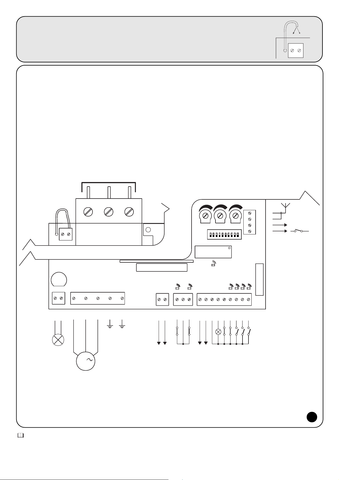
4444
44
ANTENA
19
P. P.
M
FOTO
Max 200 mA
24 Vac
SCA
COM (24V)
24 Vac Max 200mA
FCC
COM
FCA
FOTOTEST
LAMP.
230 Vac 40W
400 V
UWV
1
2
4
3
5
6
7
ALT
12
9
8
11
10
15
13
141817
16
"PIU"
OK
CH
AP
20
21
41
43
42
2° Ch RADIO
3
400
COM
RTS
400 V
F2= 0,5 A
TLM
TPTL F
+
-
+
-
+
-
2.2) Esquema de las conexiones:
Para garantizar la incolumidad del operador y para prevenir averías a
los componentes, mientras se efectúan las conexiones, o se conectan
las diferentes tarjetas: nunca alimente eléctricamente la central.
Recordamos que las entradas de los contactos de tipo NC
(Normalmente Cerrado) que no se utilicen se tienen que conectar al
"común" por medio de un conector puente; si son más de una se
colocan en SERIE entre sí. Si las entradas de los contactos de tipo
NA (Normalmente Abierto) no se utilizan, tiene que dejarse libres, si
son más de una se colocan en PARALELO entre sí. Los contactos
tienen que ser exclusivamente mecánicos y sin ningún potencial; no
se admiten conexiones de configuración como aquéllas definidas
“PNP”, “NPN”, “Open Collector”, etc.
Antes de realizar las conexiones, controle que la selección
corresponda con la tensión de alimentación disponible.
¡Un error en esta selección puede provocar graves averías a
los componentes de la central!
El dibujo indicado en la figura representa las conexiones de la central
con alimentación trifásica a 400 Voltios.
Para la conexión de la central con tensiones de alimentación de 230
Voltios monofásica o trifásica, refiérase a los dibujos de la figura 3a-3b.
nota:
La instalación y los trabajos de mantenimiento tienen que ser efectuados sólo por personal calificado y experto, de acuerdo con cuanto previsto por
la directiva 89/392 (Directiva de máquinas), especialmente la directiva EN 60204 (Equipo eléctrico de las máquinas) y siguiendo las indicaciones
dictadas por la regla del arte.
2.1) Selección de la tensión de alimentación:
La central puede funcionar correctamente con corriente trifásica o monofásica (véanse esquemas de conexión) con
tensiones de 400V o 230V. La tensión de alimentación se selecciona a través de un conector puente que se conecta
entre el borne “COM.” y el borne “230”, o bien, el borne “400” como muestra la figura.
COM
230
400
2
Page 45

230 V Monofásica
Conexión de la central con alimentación 230V monofásica
Conexión de la central con alimentación 230V trifásica
Conexión de la central con alimentación 400V trifásica
3b
3c
3a
E
45
2.3) Descripción de las conexiones:
Todas las conexiones se realizan a través de bornes situados en la
parte inferior de la tarjeta electrónica. Sólo la línea de alimentación
debe entrar por la parte superior, directamente a los bornes del
magnetotérmico.
Para la conexión a tierra de la central y del motor, use los bornes 6-7.
Si la central se alimenta desde un sistema monofásico, conecte sólo
los hilos en los primeros dos bornes situados a la izquierda del
magnetotérmico (el tercer borne no se usa). El motor monofásico y
su condensador se conectan como muestra la figura 3a.
Preste atención a la selección de la tensión de alimentación 400V
o 230V
A continuación, describimos brevemente las posibles conexiones de la central hacia el exterior.
1-2 : Luz intermitente = Conexión de la luz intermitente 220 Vca máx. 40W
3-4-5 : Motor = Línea hacia el motor 230Vca / 400Vca
6-7 : Tierra = Conexión a tierra de la central y del motor
8-9 : Fototest = Salida 24 Vca para la alimentación de los transmisores de las fotocélulas (Máx. 200mA)
10 : Fca = Salida final de carrera ABRIR
11 : Común = Común para las entradas final de carrera
12 : Fcc = Entrada final de carrera CERRAR
13-14 : 24 Vca = Alimentación de los equipos auxiliares 24 Vca Máx 200mA (400mA si no se utiliza el fototest)
15 : Común = Común para todas las entradas
16 : Indicador luminoso = Indicador luminoso cancela abierta 24 Vca máx. 2W
17 : Stop = Entrada con función de STOP (Emergencia, bloqueo, o seguridad extrema)
18 : Fotocélula = Entrada para los dispositivos de seguridad (Fotocélulas, bordes neumáticos)
19 : Paso a Paso = Entrada para el funcionamiento cíclico (ABRIR STOP CERRAR STOP )
20 : Abrir = Entrada para el movimiento de apertura
21 : Cerrar = Entrada para el movimiento de cierre
41-42 : 2° Canal Radio = Salida del posible segundo canal del radiorreceptor
43-44 : Antena = Entrada para la antena del radiorreceptor
Hay 2 conexiones para las siguientes tarjetas opcionales:
TARJETA RADIO = Conexión para los radiorreceptores fabricados por NICE
TARJETA “ PIU “ = Conexión para la tarjeta “PIU” con funciones adicionales
Para conectar las posibles tarjetas opcionales RADIO o PIU, se aconseja haber completado la instalación.
Las tarjetas opcionales no son necesarias para el funcionamiento y, si están conectadas, es más difícil localizar las posibles averías.
LN
F2= 0.5 A
COM
230
230 V Trifásica
RTS
COM
400
400 V Trifásica
RST
COM
400
1
230 Vac 40W
3
2
AP
COM
M
230 V
7
645
CH
F2= 0.5 A
1
2
230 Vac 40W
3
4
V
U
M
230 V
7
6
5
W
F2= 0.5 A
1
230 Vac 40W
3
2
V
U
M
400 V
7
645
W
Page 46

4646
2.4) Notas sobre las conexiones:
La mayoría de las conexiones es sumamente sencilla; una gran parte
de ellas son conexiones directas de un sólo usuario o contacto, en
cambio otras son conexiones un poco más complejas.
La salida “Fototest” merece una descripción particular. Esta es una
óptima solución en términos de fiabilidad para los dispositivos de
seguridad, permite lograr la “categoría 2” según la norma UNI EN
954-1 (edic. 12/1998) respecto del grupo central y fotocélulas de
seguridad.
Cada vez que se acciona una maniobra, son controlados todos los
dispositivos de seguridad implicados y la maniobra comienza sólo si
todo está en perfectas condiciones. Si en cambio la prueba no da
resultado positivo (fotocélula encandilada por el sol, cables en
cortocircuito, etc.) se localiza la avería y la maniobra no se realiza.
Todo esto es posible sólo empleando una configuración en las
conexiones de los dispositivos de seguridad que prevé la conexión
de la alimentación de los transmisores de las fotocélulas a los bornes
8-9; mientras que la alimentación de los receptores se debe conectar
a la salida de los equipos auxiliares (bornes 13-14).
Cuando se acciona un movimiento, en primer lugar se controla que
todos los receptores implicados en el movimiento den el asenso;
luego, se apaga la salida fototest y se controla que todos los
receptores señalen el hecho cortando el asenso; por último, se
reactiva la salida fototest y se controla nuevamente el asenso por
parte de todos los receptores.
Además, es aconsejable activar la sincronización cortando los
conectores puente de los transmisores; este es el único método para
garantizar que los dos pares de fotocélulas no interfieran entre sí.
Controle en el manual de las fotocélulas las instrucciones para el
funcionamiento sincronizado.
Si una entrada de FOTOCÉLULA no se utiliza (por ejemplo
FOTOCÉLULA2) y se desea igualmente la función fototest, habrá que
conectar mediante un conector puente la entrada no usada con el
borne N° 9 de la salida fototest.
TX
FOTOCÉLULA
(tarjeta PIU)
8
TX
FOTOCÉLULA
9
RX
RX
14
13
15
PIU (10)
18
Una vez que haya finalizado las conexiones del motor y de los
diferentes accesorios, es posible efectuar el ensayo de la instalación.
ATENCIÓN: las siguientes operaciones se efectúan con los
circuitos bajo tensión, la mayoría de los circuitos están
sometidos a bajísima tensión de seguridad y por lo tanto no
es peligroso; algunas piezas están sometidas a tensiones de
red, es decir, ¡MUY PELIGROSAS! Tenga mucho cuidado en lo
que está haciendo y NUNCA TRABAJE SÓLO.
Se aconseja empezar con la central en "modo manual" y con todas
las funciones desactivadas (dip-switches en Off). En caso de
problemas en modo manual, suelte el botón de mando para que el
motor se detenga inmediatamente. También controle que todos los
trimmers de regulación estén al mínimo (girados hacia la izquierda),
sólo el trimmer "FUERZA" puede estar colocado al máximo.
A) Desbloquee la cancela y colóquela a la mitad de la carrera,
luego bloquéela para que pueda abrirse o cerrarse libremente.
B) Compruebe que haya seleccionado la tensión de alimentación
correcta en la caja de conexiones situada a la izquierda del
magnetotérmico.
C) Alimente la central y controle que entre los bornes 13-14 y
entre los bornes 8-9 haya 24 Vca.
Ni bien la central está alimentada, los indicadores luminosos (LED)
que se encuentran en las entradas activas se tienen que encender;
además, transcurridos pocos segundos, el led “OK” tiene que
comenzar a centellear regularmente. Si esto no fuera así, corte
inmediatamente la alimentación y controle más atentamente las
conexiones.
El led “OK”, que está colocado en el centro de la tarjeta, tiene la
función de indicar el estado de la lógica interior: centellea
regularmente cada 1 segundo y señala que el microprocesador
interior está activo y espera el mando. Cuando el mismo
microprocesador reconoce una variación en el estado de una
entrada (tanto entrada de mando como dip-switch de las funciones)
se produce un centelleo doble rápido, incluso si la variación no
provoca efectos inmediatos. Un centelleo rápido por 3 segundos
indica que la central ha sido apenas conectada y está efectuando la
prueba de las piezas interiores; por último, un centelleo irregular e
inconstante indica que la prueba ha dado resultados negativos y, por
consiguiente, hay una avería.
D) Entonces, controle que los leds que corresponden a las
entradas con contactos tipo NC estén encendidos (todos los
dispositivos de seguridad accionados) y que los leds que
corresponden a las entradas con contactos tipo NA estén
apagados (ningún accionamiento activo); si esto no se
produce, controle las conexiones y que todos los dispositivos
funcionen correctamente.
E) Controle que todos los dispositivos de seguridad presentes en
la instalación funcionen correctamente (parada de emergencia,
fotocélulas, bordes neumáticos, etc.); cada vez que se activan,
tienen que apagarse los respectivos leds STOP,
FOTOCÉLULA.
F) Controle que los finales de carrera estén bien conectados.
Mueva la cancela y controle que al alcanzar el punto deseado
se accione el final de carrera correspondiente, apagando el
respectivo led en la central
G) Entonces, controle si el movimiento se efectúa en la dirección
correcta, es decir, controle que el movimiento previsto por la
central y aquél efectivo de las hojas correspondan. Este
control es fundamental; si la dirección es incorrecta, en
algunos casos (por ejemplo en modo semiautomático) la
cancela aparentemente podría funcionar regularmente; en
efecto, el ciclo ABRIR es parecido al ciclo CERRAR con la
diferencia fundamental de que los dispositivos de seguridad
son ignorados en la maniobra de cierre, la cual es
generalmente más peligrosa, y se accionarán durante la
3) Ensayo:
4
!
Page 47

E
47
apertura provocando un cierre sobre el obstáculo con
resultados desastrosos.
Para controlar si el sentido de rotación es correcto, es
suficiente dar un breve impulso en la entrada Paso a Paso; la
primera maniobra que la central efectúa tras haber sido
accionada siempre es ABRIR, es decir que es suficiente
controlar si la cancela se abre; por último, si el movimiento se
ha efectuado en el sentido incorrecto es necesario:
1 - Apagar la alimentación
2 - Para el motor trifásico, cambiar 2 de las 3 conexiones del
motor.
Para el motor monofásico, cambiar las conexiones “ABRIR” y
“CERRAR” del motor.
Una vez efectuado cuanto indicado, pruebe nuevamente si el sentido
de rotación es correcto, repitiendo la operación del punto “G”.
H) Pruebe un movimiento completo del accionador; se aconseja
trabajar siempre en modo manual con todas las funciones
desactivadas. Usando las entradas de mando, mueva la
cancela hasta el punto de apertura; si todo funciona
regularmente, cierre la cancela y muévala hasta el punto de
parada correspondiente.
I) Efectuar diferentes maniobras abrir-cerrar para evaluar posibles
defectos en la estructura mecánica de la automatización y
detectar la presencia de puntos de fricción particulares.
L) Pruebe el accionamiento de los dispositivos de seguridad,
FOTOCÉLULA durante la apertura no tiene ningún efecto,
durante el cierre detiene el movimiento. Si está instalada la
tarjeta PIU, pruebe también el funcionamiento de la entrada
FOTOCÉLULA2, que durante el cierre no tiene ningún efecto,
y durante la apertura detiene el movimiento. Los dispositivos
conectados a la entrada STOP trabajan tanto durante la
apertura como durante el cierre, deteniendo siempre el
movimiento.
La central tiene 3 regulaciones que se efectúan por medio de los
trimmers de regulación que actúan modificando los siguientes
parámetros:
Tiempo funcionamiento (TL):
Regula la duración máxima de la maniobra de apertura o cierre.
Tiempo pausa (TP):
En el funcionamiento “automático” regula el tiempo entre el final de la
maniobra de apertura y el comienzo de la maniobra de cierre.
Fuerza (F):
Permite regular el umbral de accionamiento del sistema amperimétrico.
Para regular el tiempo de funcionamiento TL, seleccione el modo de
funcionamiento “Semiautomático” desplazando hacia ON el dipswitch N°1 y luego regule el trimmer TL a la mitad de la carrera. Con
dichas regulaciones realice un ciclo de apertura y de cierre; si fuera
necesario, actúe sobre la regulación del trimmer TL de manera que
sea suficiente para cumplir toda la maniobra y que todavía quede un
margen de 2 ó 3 segundos.
Si colocando el trimmer TL al máximo no se obtiene un tiempo
suficiente, corte el conector puente TLM, colocado en el circuito
impreso entre los trimmers TL y TP, para obtener un tiempo de
Funcionamiento mayor.
Para regular el Tiempo Pausa TP, seleccione el modo de
funcionamiento “Automático” desplazando hacia ON el dip-switch
N°2, luego regule el trimmer TP a placer. Para el control, ejecute una
maniobra de apertura y controle el tiempo que transcurre antes del
cierre automático.
Preste mucha atención cuando regule el trimmer FUERZA (F), puesto
que puede influir sobre el grado de seguridad de la automatización.
Para la regulación hay que actuar por tentativas sucesivas, midiendo
la fuerza que sirve para que el sistema se accione. Observe las
indicaciones del próximo capítulo.
La regulación no es lineal en toda la carrera del trimmer, sino que está
concentrada sólo en una zona; por dicho motivo, puede suceder que
en la primera parte del trimmer la regulación no tenga ningún efecto
y que luego sea suficiente girar un poco el trimmer para obtener
amplias variaciones. El motivo de esta escasa linealidad es causada
por la necesidad de garantizar el funcionamiento con una amplia
gama de motores monofásicos y trifásicos.
4) Regulaciones:
5) Sistema de deteccion de los obstaculos:
Esta central está equipada con un sistema de detección de los
obstáculos que se basa sobre algunas técnicas de control del
esfuerzo del motor, en función de la potencia absorbida por el
mismo. Este sistema es llamado “amperimétrico” y provoca la
inversión o la parada de la maniobra, de acuerdo con el modo de
funcionamiento programado.
En la central el sistema de control puede funcionar de dos modos:
“normal” o “inteligente” que se seleccionan a través del dip-switch N°8
(véase el capítulo "Funciones programables).
En el modo “normal” se acciona cuando la potencia absorbida por el
motor alcanza el umbral regulado con el trimmer fuerza. El nivel es
fijo y tiene la desventaja que los aumentos de potencia absorbida,
causadas por variaciones de tensión, temperatura o demás, pueden
provocar accionamientos aparentemente injustificados.
El modo "inteligente" se ha desarrollado para superar este límite.
Tiene la particularidad de adecuar el nivel de accionamiento, además
del punto regulado con el trimmer, a través de una acción inteligente
que discrimina variaciones lentas causadas por los motivos
antedichos de las variaciones rápidas provocadas por un obstáculo.
nota: en la etapa inicial del movimiento y por una duración de 1,5
segundos, en ambos sistemas no está activa la detección
amperimétrica de los obstáculos.
La regulación de la fuerza, junto con otras soluciones, debe
respetar las normativas europeas prEN 12453 (seguridad en el uso
de puertas motorizadas – requisitos y clasificaciones) y prEN 12445
(seguridad en el uso de puertas motorizadas – métodos de ensayo).
Dichas normas requieren el uso de medidas para limitar las fuerzas
en el movimiento de las puertas automáticas.
5
TLM
TPTL F
+
-
+
-
+
-
Page 48

4848
6) Modos de funcionamiento:
En el funcionamiento en modo manual la entrada ABRIR permite el
movimiento de apertura y la entrada CERRAR permite el movimiento
de cierre. El PASO a PASO permite el movimiento de apertura y cierre
alternativamente.
Ni bien cesa el mando de entrada el movimiento se detiene. Durante
la apertura el movimiento se para cuando se accionan los finales de
carrera, o bien si falta el permiso de la FOTOCÉLULA 2 (en la tarjeta
PIU); en cambio, durante el cierre, el movimiento se para si falta el
asenso de FOTOCÉLULA. El accionamiento de STOP provoca una
parada inmediata del movimiento tanto durante la apertura como
durante el cierre. Cuando el movimiento se detiene, deje de accionar
el mando en entrada antes de poder iniciar con un nuevo movimiento.
Durante el funcionamiento en uno de los dos modos automáticos
(semiautomático, automático o cerrar siempre) un impulso de
accionamiento en la entrada ABRIR provoca el movimiento de
apertura. Un impulso sobre PASO a PASO provoca la apertura o el
cierre alternativamente. Un segundo impulso sobre PASO a PASO, o
sobre la misma entrada que ha comenzado el movimiento, provoca
un Stop.
El accionamiento de STOP provoca una parada inmediata del
movimiento, tanto durante la apertura como durante el cierre.
Si en una entrada de mando en vez de un impulso se mantiene una
señal continua, se provoca un estado de “preponderancia” en el cual
las demás entradas quedan desactivadas (útil para conectar un reloj
o un selector Noche-Día).
Si se selecciona el modo de funcionamiento automático, tras una
maniobra de apertura, se efectúa una pausa y luego el cierre. Si
durante la pausa se acciona FOTOCÉLULA el temporizador se
restablecerá con un nuevo tiempo de pausa; si en cambio durante la
pausa se acciona STOP, la función de cierre se pone a cero y se pasa
a un estado de STOP.
Durante la apertura el accionamiento de FOTOCÉLULA no tiene
ningún efecto, mientras que la FOTOCÉLULA2 (en la tarjeta PIU)
provoca la inversión del movimiento; durante el cierre, el
accionamiento de FOTOCÉLULA provoca una inversión del
movimiento, luego una nueva pausa y finalmente un nuevo cierre.
La central dispone de una serie de microinterruptores que permiten
activar varias funciones para que la instalación sea más adecuada a
la exigencias del usuario y más segura bajo las diversas condiciones
de empleo. Todas las funciones se activan poniendo el respectivo
dip-switch en la posición “On”, mientras que con el dip-switch
correspondiente en “Off” no están activas.
ATENCIÓN: algunas de las funciones programables están vinculadas
con aspectos de la seguridad; evalúe con mucha atención los
efectos de una función y verifique cuál es la función que da la mayor
seguridad posible.
Durante el mantenimiento de una instalación, antes de modificar una
función programable, evalúe el motivo por el cual durante la
instalación se habían tomado ciertas decisiones, y controle si la
seguridad se verá perjudicada por la nueva programación.
7) Programación:
7.1) Funciones programables:
El dip-switch FUNCIONES permite seleccionar los diferentes modos de funcionamiento e introducir las funciones deseadas según la siguiente
tabla:
Switch 1-2: Off-Off = Movimiento “Manual”, es decir Pulsador de interrupción automática
On -Off = Movimiento “Semiautomático”
Off-On = Movimiento “Automático”, es decir cierre automático
On -On = Movimiento “Automático + cerrar siempre”
Switch 3: On = Funcionamiento en común < no disponible en modo manual >
Switch 4: On = Centelleo previo
Switch 5: On = Cierra 5” después de Fotocélula < sólo en modo automático >
Switch 6: On = Dispositivo de seguridad “Fotocélula” también durante apertura
Switch 7: On = Fototest
Switch 8: On = Sistema amperimétrico inteligente
Switch 9: On = Inversión parcial por accionamiento del sistema amperimétrico < desconectado en modo manual >
Switch 10: On = Freno
Un dip-switch en “Off” no activa la función; si está en “On” activa la función descripta.
Algunas funciones son posibles en determinadas condiciones que son señaladas con las notas entre los caracteres “<...>”.
6
on
off
1
Page 49

E
49
7.2) Descripción de las funciones:
A continuación mencionamos brevemente las funciones que se pueden introducir colocando en “On” el dip-switch respectivo.
Switch 1-2: Off-Off = Movimiento “Manual” (Pulsador de interrupción automática)
On-Off = Movimiento “Semiautomático”
Off-On = Movimiento “Automático” (cierre automático)
On-On = Movimiento “Automático + Cerrar siempre”
Durante el funcionamiento “Manual” el movimiento se efectúa sólo hasta que se acciona el mando (botón apretado).
En modo “Semiautomático” es suficiente dar un impulso de mando para que se cumpla todo el movimiento, hasta que termina el Tiempo
Funcionamiento o se alcanza el final de carrera. En el funcionamiento en modo “Automático”, después de la apertura, se efectúa una pausa
y luego un cierre automático.
La función “Cierre Siempre” se acciona tras un corte de alimentación, si detecta que la cancela está abierta, se pone en marcha
automáticamente una maniobra de cierre, antecedida por 5 segundos de centelleo previo.
Switch 3: On = Funcionamiento en común (no disponible en modo Manual)
Durante el funcionamiento en común, una vez que se puso en marcha un movimiento de apertura, la maniobra no puede ser interrumpida
por otros impulsos de mando en PASO A PASO o ABRIR, hasta que no finalice el movimiento de apertura.
Durante el movimiento de cierre, al efectuar un nuevo accionamiento, se produce la parada y la inversión del movimiento y se abre
nuevamente.
Switch 4: On = Centelleo previo
Al recibir el impulso de mando, primero se activa la luz intermitente, luego, transcurridos 5 segundos (2 seg. si está en modo manual) inicia
el movimiento.
Switch 5: On = Cierra 5 segundos después de Fotocélula (sólo si está en modo automático)
Esta función permite mantener la cancela abierta sólo por el tiempo necesario para el paso; en efecto, después de la activación de
FOTOCÉLULA, el cierre se producirá con una pausa de 5 segundos, independientemente del Tiempo Pausa regulado.
Switch 6: On = Dispositivo de seguridad (Fotocélula) también durante apertura
Normalmente, el dispositivo de seguridad “Fotocélula” está activo sólo durante la maniobra de cierre, si el switch N°6 se coloca en "On" el
accionamiento del dispositivo de seguridad provoca una interrupción del movimiento también durante la apertura.
Si está en Semiautomático o Automático, el movimiento de apertura se reanudará inmediatamente después de la desconexión.
Switch 7: On = Fototest
Esta función permite ejecutar en cada comienzo de maniobra un control de la eficiencia de las fotocélulas, aumentando la seguridad del grupo
central + fotocélulas, hasta lograr la “categoría 2” de acuerdo con la norma UNI EN 954-1 (edic. 12/1998).
Para utilizar esta función, las fotocélulas se deben conectar como indicado en el esquema de la figura 4.
Switch 8: On = Sistema amperimétrico inteligente
Esta función permite seleccionar el modo amperimétrico utilizado. Si el switch está colocado en “Off” está activo el modo amperimétrico
normal; si está colocado en “On” se activa el sistema amperimétrico inteligente.
Switch 9: On = Inversión parcial por el accionamiento del sistema amperimétrico < desconectado en modo manual >
Cuando se acciona el sistema amperimétrico, generalmente se invierte el movimiento; con el switch colocado en “On” se realiza una inversión
por 1,5 segundos, luego se producirá una parada.
Switch 10: On = Freno
Esta función permite reducir la inercia de la hoja al final de la maniobra. Por 1 segundo se aplica al motor una corriente que garantiza una
parada rápida, incluso en automatizaciones con elevada energía cinética acumulada
Page 50

5050
8) Utilización de 2 centrales en hojas opuestas:
Para una automatización compuesta de 2 hojas que trabajan de modo
opuesto, hay que usar dos centrales, tal como muestra la figura de
abajo. Los motores y los finales de carrera deben estar conectados
uno a cada central, la luz intermitente y el Indicador Cancela abierta
pueden estar conectados, indiferentemente, a una de las dos hojas o,
si se desea, se puede instalar uno por cada central.
Si se usa la función fototest, emplee la salida de una sola central.
Las entradas se deben colocar en paralelo entre sí. El “Común” se
puede conectar a una de los 2 centrales.
Conecte juntos los 0 voltios (borne 13) de las dos centrales.
Es oportuno conectar la función "En común (Colectiva)" (Dip-Switch 3),
que permite sincronizar de nuevo las hojas si las 2 centrales pierden
la sincronización.
AP
CH
"PIU"
FOTO
ALT
Max 200 mA
24 Vac
SCA
COM (24V)CHAP
P. P.
18
13151417162119
20
24 Vac Max 200mA
8
9
FCC12COM11FCA
10
FOTOTEST
5
4
3
6
7
VUWCH
AP
COM
230 V
400 V
2
1
LAMP.
230 Vac 40W
42
41
44
43
RADIO
COM
230
400
F2= 0.5 A
F1= 0.5 A
400 V230 V
TL TP F
OK
TLM
230 Vac 40W
LAMP.
FCA
COM
FCC
24 Vac
Max 200 mA
400 V
230 V
21
F2= 0.5 A
2
1
7
6
3
4
5
101112
9
8
20
19161714151318
COMAPCHW
V
U
OK
"PIU"
AP
CH
TPTL
F1= 0.5 A
RADIO
TLM
COM
400
230
230 V 400 V
42
41
44
43
F
9) Accesorios opcionales:
- Tarjeta “PIU”
La central contiene todas las funciones que se utilizan en una
instalación normal. Para suplir la necesidades de instalaciones
especiales, se ha creado una tarjeta opcional "Tarjeta PIU", que
permite lograr nuevas funciones como señales de semáforo, luz de
cortesía, electrocerradura, Fotocélula 2, apertura parcial, etc.
- Tarjeta “RADIO”
En la central hay un conector para conectar una tarjeta radio,
fabricada por Nice, que permite actuar sobre la entrada de PASO A
PASO y así accionar la central a distancia con un transmisor.
7
Page 51

E
51
10) Mantenimiento:
La tarjeta como pieza electrónica no requiere ningún tipo de
mantenimiento especial. De todas maneras, controle periódicamente
(por lo menos dos veces por año) la perfecta eficiencia y la regulación
del dispositivo de control del sistema amperimétrico del motor; si
fuera necesario, actúe sobre el trimmer de regulación.
Controle que los dispositivos de seguridad (fotocélulas, bordes
neumáticos, etc.) y que la luz intermitente funcionen correctamente.
10.1) Imedidas de protección del medio ambiente:
Este producto está constituido por varios tipos de materiales de los
cuales algunos se pueden reciclar.
Infórmese acerca de los sistemas de reciclaje o eliminación del
producto, ateniéndose a las normas locales vigentes.
10.2) Características técnicas de la central:
Alimentación de red : 400 Vca o bien 230 Vca ± 10%, 50 ó 60Hz
Corriente Máx a los motores : 4A
Salida equipos auxiliares : 24Vca, corriente máxima 200mA (400mA si no se usa fototest)
Salida fototest : 24Vac, corriente máxima 200mA
Salida luz intermitente : para las luces intermitentes de 230Vca, potencia máxima 40 W
Salida indicador luminoso cancela abierta “SCA” : para indicadores luminosos de 24Vca, potencia máxima 2 W
Tiempo de funcionamiento : Ajustable desde <3 hasta>120 s, o bien desde <90 hasta>210 s con TLM
Tiempo de Pausa : Ajustable desde <5 hasta>200 s
Temperatura de servicio : -20 ÷ 70 °C
Page 52

5252
6 Sposoby funkcjonowania
7 Programowanie
7.1 Funkcje z możliwością programowania
7.2 Opis funkcji
8 Zastosowanie 2 centralek do drzwi skrzydłowych
przeciwwstawionych
9 Akcesoria dodatkowe
10 Czynności konserwacyjne
10.1 Informacje związane ze środkami ochrony środowiska
10.2 Dane techniczne centrali
Mindy A500
Przedmowa:
Niniejsza instrukcja przeznaczona jest tylko dla techników z odpowiednimi
kwalifikacjami umożliwiającymi instalowanie. Żadna z informacji zawartych
w niniejszym wydaniu nie może służyć końcowemu użytkownikowi!
Instrukcja ta jest załącznikiem do centrali A500 i nie może być używana do
innych produktów!
Ważne uwagi:
Centrala A500 jest przeznaczona do sterowania aktuatora
elektromechanicznego do automatyzacji bram, bramek lub drzwi.
Użytkowanie powinno być zgodne z aktualnie obowiązującym normami.
Naszym obowiązkiem jest podkreślenie faktu, że automatyzacja, którą
będziecie wykonywać, jest uważana za “część konstrukcyjną maszyny” i
dlatego też podlega normie europejskiej 89/392 CEE (normy maszyn).
Powyższa norma określa przede wszystkim to, że
- Instalacja maszyny ma być wykonywana przez doświadczonych
wyspecjalizowanych techników.
- Osoba wykonująca instalowanie powinna wcześniej wykonać “analizę
ryzyka” maszyny.
- Instalowanie ma być wykonywane “bezbłędnie”, to znaczy zgodne z
zachowaniem obowiązujących przepisów;
- Po zakończeniu instalowania właściciel maszyny powinien otrzymać
“deklarację zgodności”.
Jest więc jasne, że instalowanie jak i interwencje konserwacyjne mają być
wykonywane przez techników posiadających odpowiednie kwalifikacje
zgodnie z tym co przewiduje prawo, normy i dyrektywy aktualnie
obowiązujące.Przy projektowaniu i realizacji własnych urządzeń Nice
przestrzega przepisów dotyczących danego produktu (patrz deklaracja
zgodności w załączniku).
Jest to więc podstawą aby instalator przystosowywał się do
obowiązujących przepisów.
Personel bez kwalifikacji lub bez znajomości norm odnoszących się do
„bram lub drzwi automatycznych” ma absolutnie wstrzymać się od
wykonywania wszelkich linii czy instalacji.
Kto nie przestrzega norm jest odpowiedzialny za ewentualne szkody
wyrządzone niewłaściwą instalacją!
Przed przejściem do wykonywania instalacji należy uważnie przeczytać
poniższą instrukcję.
Szczególna ostrożność należy zachować w zakresie użytkowania tego
produktu pod kątem jego zgodności z dyrektywą “Niskiego Napięcia”
73/23/CEE wraz z późniejszymi zmianami 93/68/CEE:
- Produkt niniejszy odpowiada cechom wymaganym przez dyrektywę
“Niskiego Napięcia’ o ile zastosowany jest w konfiguracjach przewidzianych
w niniejszym podręczniku użytkownika oraz w połączeniu z artykułami
wymienionymi w katalogu produktów firmy Nice S.p.a. Charakterystyki te
mogłyby nie być gwarantowane, jeśli produkt użytkowany jest w
konfiguracjach z innymi produktami, nieprzewidzianymi; zabrania się
użytkowania niniejszego produktu w połączeniu z takimi wyrobami póki
osoba dokonująca instalacji nie upewni się co do zgodności z
wymaganiami przewidywanymi przez dyrektywę.
Szczególną uwagę należy zwrócić na użytkowanie niniejszego produktu z
punktu widzenia dyrektywy o “zgodności elektromagnetycznej 89/336/CEE
wraz z późniejszymi zmianami 92/31/CEE oraz 93/68/CEE:
- Niniejszy produkt został poddany badaniom w zakresie zgodności
elektromagnetycznej w skrajnych sytuacjach użytkowania, w konfiguracjach
przewidywanych w niniejszym podręczniku użytkownika oraz w połączeniu z
artykułami znajdującymi się w katalogu produktów firmy Nice S.p.a. Zgodność
elektromagnetyczna może nie być zagwarantowana jeśli produkt użytkowany
będzie w połączeniu z innymi wyrobami nieprzewidzianymi; zabronione jest
użytkowanie niniejszego produktu w takich sytuacjach póki osoba dokonująca
instalacji nie upewni się co do zgodności z wymaganiami zawartymi w dyrektywie.
Spis:
1 Opis produktu
2 Instalowanie
2.1 Instrukcje instalowania
2.2 Selekcja napięcia zasilania
2.3 Opis połączeń
2.4 Uwagi związane z połączeniami
3 Próby odbiorcze
4 Regulacje
5 System odczytu przeszkód
!
!
!
Page 53

PL
53
R
Q
S
POMN
AP
CH
L
H
I
G
F
T
A
U
BC
D
E
TLM
F2= 0.5 A
"PIU"
OK
1
TPTL F
F1= 0.5 A
COM
RADIO
400
230
A Selektor zasilania 230 / 400 Volt
B Bezpiecznik magneto termiczny
C Transformator zasilania
D Bezpiecznik topikowy zasilania cent. (500mA)
E Trymer (wyłącznik regulacyjny)
F Tablica zaciskowa radio
G Dip-Switch selekcji funkcji
H Dioda (Led) sygnalizacji stanu OK
I Łącznik sterowań na drzwiach
L Dioda sygnalizacyjna stanu wejść
M Tablica zaciskowa Wejść / Wyjść sterowania
N Tablica zaciskowa wejścia wył. krańcowego
O Tablica zaciskowa wyjścia fototestu
P Wyjście zasilania silnika
Q Wyjście lampy sygnalizacyjnej
R Bezpiecznik topikowy lampy sygn. (500mA)
S Wyłącznik zdalny ruchu silnika
T Przekażnik uaktywnienia lampy sygnalizacyjnej
U Przekażnik uaktywnienia hamulca
1) Opis Produkt:
Centrala do automatyzacji bram i drzwi automatycznych służy do
sterowania silnikiem na prąd przemienny typu trójfazowego lub
jednofazowego 230V lub 400V. Jest zaopatrzona w system odczytu
przeszkód (zabezpieczenie przed zgnieceniem) i w system
hamowania, który redukuje bezwładność w fazie zatrzymania.
Posiada szereg funkcji, które można wybrać poprzez “dip-switch” (mini
selektory) i poprzez regulację trymerem. W centrali przy wejściach
znajdują się diody (led), które informują o ich stanie, dodatkowa dioda
obok mikroprocesora informuje o działaniu wewnętrznego systemu.
2) Instalowanie:
Przed przejściem do wykonania jakichkolwiek czynności należy
sprawdzić stan i trwałość mechaniczną bramy, zabezpieczenia i
odległości minimalne. Wykonać uważną i dokładną “analizę ryzyka”
związanego z automatyzacją, określić jakie należy zastosować
zabezpieczenia i zainstalować w każdym przypadku urządzenie
zatrzymania w razie alarmu.
Sprawdzić uważnie “urządzenie mechanicznego zatrzymania biegu”;
powinno ono posiadać formę i strukturę, taką aby zatrzymać ruch silnika
w każdym momencie, powinno “wchłonąć” bez jakiejkolwiek deformacji
całą energię kinetyczną zebraną w ruchu.
Nie instalować bez uprzedniego przystosowania
“urządzenia mechanicznego zatrzymania biegu” !
Poza normami, które związane są z podstawowymi instalacjami
elektrycznymi, instalacją maszyn, drzwi i bram automatycznych poniżej
zostały przedstawione dodatkowe uwagi odnoszące się do centrali,
których celem jest stworzenie instalacji pewniejszej i o wyższym stopniu
bezpieczeństwa.
-Linia zasilania centrali ma być zabezpieczona przełącznikiem magneto
termicznym lub systemem bezpieczników topikowych 5A; polecany jest
przełącznik różnicowy, jest on niekonieczny w przypadku, gdy jest już
zamontowany w instalacji w wejściu.
-Centrala zasilona jest przewodem: 5 x 1,5 mm
2
(3 fazy + neutralny +
uziemienie); w wypadku gdy odległość pomiędzy centralą i uziemieniem
jest większa od 30 m wówczas w pobliżu centrali należy zainstalować
urządzenie dyspersyjne do ziemi.
-Połączenia komponentów z niskim napięciem zabezpieczeń należy
wykonać przewodami z minimalnym przekrojem równym 0,25 mm
2
.
Zastosować przewody izolowane gdy długość ich jest większa od 30 m
łącząc oplot uziemienia tylko po stronie centrali.
-Stosować wyłącznie przewody (przewody pojedynczo izolowane z
dodatkową wspólną izolacją) i nigdy przewody pojedyncze nawet gdy
są zabezpieczone wewnątrz odpowiednich kanalików.
-Unikać wykonania połączeń do przewodów w skrzyniach
podziemnych nawet gdy są one wodoszczelne.
Sprawdzić, czy materiał którym dysponujemy jest odpowiedni do
przewidzianego typu zastosowania.
Wybór właściwego sposobu instalowania centrali jest podstawą
bezpieczeństwa i dobrego zabezpieczenia przed czynnikami
atmosferycznymi. Należy pamińtać, że niektóre części w centrali są pod
napięciem i że części elektroniczne są bardzo delikatne.
Centrala dostarczana jest w pojemniku, który, gdy zostanie
odpowiednio zainstalowany, gwarantuje przewidywany stopień
bezpieczeństwa: IP 55 (według normy CEI 70-1 i IEC 529), można ją
więc zainstalować na zewnątrz.
Zawsze należy także przestrzegać warunków przedstawionych poniżej:
-Zainstalować centralę na powierzchni stałej, płaskiej i odpowiednio
zabezpieczonej przed uderzeniami, uważając aby część dolna znalazła
się na wysokości 40 cm od podłoża.
-Założyć odpowiednie przewłoki lub prowadnice przewodów rurowych
tylko w części dolnej centrali: w żadnym wypadku nie wolno wykonywać
otworów w ściankach bocznych i w ściance górnej: przewody mają
wchodzić do centrali tylko przez ściankę dolną!
1
!
Page 54

5454
44
ANTENA
19
P. P.
M
FOTO
Max 200 mA
24 Vac
SCA
COM (24V)
24 Vac Max 200mA
FCC
COM
FCA
FOTOTEST
LAMP.
230 Vac 40W
400 V
UWV
1
2
4
3
5
6
7
ALT
12
9
8
11
10
15
13
14
18
17
16
"PIU"
OK
CH
AP
20
21
41
43
42
2° Ch RADIO
3
400
COM
RTS
400 V
F2= 0,5 A
TLM
TPTL F
+
-
+
-
+
-
2.2) Schemat połącze:
W celu zagwarantowania bezpieczeństwa operatorowi i aby nie uszkodzić
części podczas wykonywania połączeń i zakładania poszczególnych kart
elektronicznych centrala nie ma być zasilana elektrycznie.
Przypominamy, że nieużywane wejścia kontaktów typu NC (Zwykle
Zamknięte) mają być podłączone do „wspólnego” mostka; w przypadku,
gdy jest ich więcej mają one być między sobą ustawione SZEREGOWO.
Nie używane wejścia kontaktów typu NA (Zwykle Otwarte) mają pozostać
wolne, gdy jest ich więcej należy je ustawić między sobą RÓWNOLEGLE.
Kontakty te powinny być kontaktami mechanicznymi i wolne od
jakiejkolwiek energii potencjalnej, niedozwolone są połączenia stopniowe
takie jak "PNP", "NPN", "Open Collector" itp.
Przed rozpoczęciem czynności związanych z podłączeniem należy
sprawdzić napięcie zasilania.
Błąd w podłączeniu napięcia może spowodować poważne
szkody w elementach centrali!
Rysunek przedstawia połączenia centrali z zasileniem trójfazowym
400 Volt.
Połączenia centrali z napięciami 230 Volt jednofazowym lub trójfazowym
przedstawione są na rysunku 3a-3b.
uwaga:
Instalowanie i sukcesywne interwencje konserwacyjne mają być wykonywane przez doświadczony personel z odpowiednimi kwalifikacjami, przestrzegając
w pełni norm przewidzianych w dyrektywie 89/392 (Dyrektywy maszyny), a w szczególności EN 60204 (Wyposażenie elektryczne maszyn) i kierując się
wiedzą fachową.
2.1) Selekcja napięcia zasilania:
Centrala może pracować przy zasilaniu odpowiednio trójfazowym lub jednofazowym (patrz schematy połączeń) z napięciem
400V lub 230V. Selekcja napięcia zasilania jest wykonywana poprzez mostek, który ma być założony pomiędzy zaciskiem
“COM” i zaciskiem “230” lub zaciskiem “400” tak jak zostało przedstawione na rysunku.
COM
230
400
2
Page 55

PL
55
230
COM
230 V Jednofazowym
LN
230 V
AP
COM
3
1
2
F2= 0.5 A
CH
645
7
M
230 Vac 40W
2.3) Pis połączeń:
Wszystkie połączenia wykonywane są poprzez odpowiednie zaciski
znajdujące się w części dolnej karty elektronicznej. Tylko linia zasilająca
ma wchodzić od strony górnej bezpośrednio do zacisków magneto
termicznych.
Uziemienie centrali i silnik najlepiej podłączyć do zacisków 6-7.
W wypadku zasilania centrali systemem jednofazowym mają być
podłączone tylko dwa przewody na dwóch pierwszych zaciskach po
lewej stronie magneto termicznego (trzeci zacisk nie będzie używany).
Silnik jednofazowy i odpowiadający mu kondensator zostaną
podłączone tak jak przedstawione jest na rysunku
Należy zwrócić uwagę na wybór napięcia zasilania 400V lub 230V.
Przedstawiamy krótki opis możliwych połączeń centrali w kierunku na zewnątrz.
1-2 : Lampa sygnaliz. = Połączenie lampy sygnalizacyjnej 220 Vpp max 40W
3-4-5 : Silnik = Linia w kierunku do silnika 230Vpp / 400Vpp
6-7 : Uyiemienie = Połączenie uziemienia centrali i silnika
8-9 : Fototest = Wyjście 24 Vpp zasilenia nadajników fotokomórek (Max 200mA)
10 : Wył.krańcowy = Wejście wyłącznika krańcowego OTWIERA
11 : Wspólny = Wspólny dla wejść wyłącznika krańcowego
12 : Wył.krańcowy = Wejście wyłącznika krańcowego ZAMYKA
13-14 : 24 Vpp = Zasilenie funkcji 24 Vpp Max 200mA (400mA gdy nie używa się fototestu)
15 : Wspólny = Wspólny dla wszystkich wejść
16 : DiodaC.A. = Dioda bramki otwartej 24 Vpp max 2W
17 : Stop = Wejście z funkcją ALT (Alarm, blokada i zabezpieczenie końcowe)
18 : Foto = Wejście urządzeń bezpieczeństwa (Fotokomórki, żebra pneumatyczne)
19 : Skok po skoku = Wejście pracy cyklicznej (OTWIERA STOP ZAMYKA STOP)
20 : Otwiera = Wejście dla ruchu przy otwieraniu
21 : Zamyka = Wejście dla ruchu przy zamykaniu
41-42 : 2Ą Ch Radio = Wejście ewentualnego kanału odbioru radiowego
43-44 : Antena = Wejście anteny odbioru radiowego
Obecne są 2 łączniki wsadowe następujących kart elektronicznych opcjonalnych:
SCHEDA RADIO =Wsad odbiorników radiowych wyprodukowanych przez NICE
SCHEDA “PIU“ =Wsad karty “PIU” z dodatkowymi funkcjami
Polecamy, aby przed założeniem ewentualnych kart elektronicznych opcjonalnych RADIO lub PIU skończyć instalowanie podstawowe.
Karty opcjonalne nie sć niezbędne do pracy, gdy są założone utrudniają znalezienie anomalii.
Połączenie centrali z zasileniem 230V jednofazowym
Połączenie centrali z zasileniem 230V trójfazowym
Połączenie centrali z zasileniem 400V trójfazowym
3b
3c
3a
230 V Trójfazowym
RTS
F2= 0.5 A
COM
400
400 V Trójfazowym
RST
COM
400
1
230 Vac 40W
3
4
2
V
U
M
230 V
7
6
5
W
F2= 0.5 A
1
230 Vac 40W
3
2
V
U
M
400 V
7
645
W
Page 56

5656
2.4) Uwagi związane z połączeniami:
Większość połączeń jest bardo łatwa do wykonania, duża część to
połączenia bezpośrednie do pojedynczego użytkownika (odbiornika)
lub kontaktu, część połączeń jest bardziej skomplikowanych.
Szczegółowego opisu wymaga wyjście “fototestu”, jest to optymalne
rozwiązanie pod względem gwarancji w stosunku do urządzeń
zabezpieczających; pozwala na osiągnięcie “2 kategorii” normy UNI EN
954-1 (wydanie 12/1998) w zakresie centrali i fotokomórek
zabezpieczających. Przy każdym rozruchu kontrolowane są
odpowiednie urządzenia bezpieczeństwa i gdy wszystko jest w
porządku możliwy jest rozruch. Gdy jednak test nie da pozytywnych
wyników (fotokomórka “oślepiona” przez słońce, spięcie na
przewodach, itp.) zostanie wykryta anomalia i ruch nie odbędzie się.
To wszystko jest możliwe wtedy, gdy zostanie zastosowana konfiguracja
połączeń urządzeń bezpieczeństwa, które przewiduje połączenie zasilania
nadajników fotokomórek do zacisków 8-9, zasilanie odbiorników ma
znajdować się na wyjściu funkcji (zaciski 13-14).
Gdy zarządzany jest ruch najpierw sprawdzane jest czy wszystkie
odpowiednie do danego ruchu odbiorniki „dają pozwolenie”, póżniej
zostanie wyłączone wyjście fototestu i sprawdzone czy wszystkie
odbiorniki sygnalizują fakt, że pozwolenie zostało im anulowane; na
koniec ponownie uaktywnia się wyjście fototestu i ponownie sprawdza
się wydawanie pozwolenia ze wszystkich odbiorników.
Dobrze by było aby uaktywnić synchronizm poprzez przerwanie
odpowiednich mostków w nadajnikach, jest to jedyny sposób
zagwarantowania aby dwie pary fotokomórek nie przeszkadzały sobie
wzajemnie. Należy sprawdzić w instrukcjach fotokomórek sposób
funkcjonowania w synchronizmie.
W przypadku, gdy jedno wejście FOTO nie zostanie użyte (na przykład
FOTO2) i żądana jest praca fototestu, należy stworzyć mostek nie
używanego wejścia z zaciskiem nr 9 wyjścia fototestu.
TX
FOTO 2
(karta elektroniczna PIU)
8
TX
FOTO
9
RX
RX
14
13
15
PIU (10)
18
Po zakończeniu połączeń silnika i poszczególnych części można
przejść do fazy prób i kontroli ostatecznych instalacji.
UWAGA: poniższe czynności będą wykonywane przy
obwodach pod napięciem, większość obwodów jest pod
bardzo niskim napięciem, oznacza to, że nie są
niebezpieczne, ale niektóre części są pod napięciem sieci,
dlatego też są BARDZO NIEBEZPIECZNE! Należy wykonywać
te czynności bardzo ostrożnie i NIGDY NIE PRACOWAĆ
SAMODZIELNIE!
Zaleca się aby zacząć prace przy centrali w systemie “ręcznym” i przy
wyłączonych wszystkich funkcjach (dip-switch Off); przy jakimkolwiek
zagrożeniu, w systemie ręcznym, wystarczy zwolnić przycisk i silnik
natychmiast zatrzyma się. Sprawdzić czy wszystkie trymery regulacyjne
są na pozycji minimalnej (przekręcone w kierunku przeciwnym do ruchu
wskazówek zegara), tylko trymer “SIŁA” może być w maksymalnej
pozycji.
A) Odblokować bramę i otworzyć ją do połowy po czym zablokować,
w ten sposób jest wolna do ruchu otwierania jak i zamykania.
B) Sprawdzić czy na tablicy zacisków po lewej stronie magneto
termicznego zostało wybrane właściwe napięcie.
C) Podłączyć napięcie do centrali i natychmiast sprawdzić czy
pomiędzy zaciskami 13-14 i zaciskami 8-9 napięcie jest równe
24 Vpp.
Natychmiast po podłączeniu zasilania do centrali, diody (LED), które
znajdują się na wejściach aktywnych powinny zaświecić się i po chwili
dioda “OK” powinna zacząć świecić się z regularnymi przerwami. W
przeciwnym wypadku należy odłączyć zasilanie i ponownie dokładniej
sprawdzić połączenia.
Dioda “OK” umieszczona pośrodku karty ma za zadanie sygnalizować
stan wewnętrznego systemu: regularne świecenie się z przerwą 1
sekundy wskazuje, że mikroprocesor wewnętrzny jest uaktywniony i
oczekuje na rozkazy. Wówczas, gdy ten mikroprocesor rozpoznaje
anomalię stanu wejść (wejść sterowań jak i dip - switch funkcji) wydaje
podwójny sygnał świetlny z szybkimi przerwami, zdarza się to również
wtedy, gdy te anomalie nie powodują natychmiastowych zmian.
Świecenie z przerwami 3 sekundowymi oznacza, że centrala dopiero co
została zasilona i wykonuje test części wewnętrznych, świecenie w
sposób nieregularny i niestały wskazuje, że test nie dał pozytywnych
wyników i że istnieje jakaś awaria.
D) Teraz należy sprawdzić czy diody wejść z kontaktami typu NC
(Zwykle Zamknięte) świecą się (wszystkie zabezpieczenia
uaktywnione) i czy diody wejść typu NA (Zwykle Otwarte) nie
świecą się (bez rozkazu); w przeciwnym wypadku należy
sprawdzić połączenia i funkcjonowanie poszczególnych
urządzeń.
E) Sprawdzić funkcjonowanie poszczególnych urządzeń
bezpieczeństwa występujących w instalacji (zatrzymanie w
alarmie, fotokomórki, żebra pneumatyczne, itp.), przy każdym
pojedynczym uaktywnieniu powinna wyłączyć się odpowiednia
dioda: ALT, FOTO
F) Sprawdzić połączenie wyłączników krańcowych; poruszyć
bramą i sprawdzić, czy w momencie osiągnięcia odpowiedniej
pozycji, wyłącznik krańcowy zainterweniuje i wyłączy się
odpowiednia dioda na centrali.
G) Teraz należy sprawdzić czy ruch odbywa się we właściwym
kierunku, to znaczy sprawdzić czy ruch efektywny skrzydeł bramy
odpowiada ruchowi przewidzianemu w centrali. Ta kontrola jest
bardzo ważna; gdy w niektórych przypadkach (na przykład w
systemie półautomatycznym) kierunek jest zmieniony, to brama
może funkcjonować regularnie ponieważ cykl OTWIERA jest
podobny do cyklu ZAMYKA z różnicą taką, że urządzenia
bezpieczeństwa nie będą działały w ruchu zamykania, który jest
najbardziej niebezpieczny i zainterweniują w fazie otwierania
tworząc ponowny ruch zamykania na przeszkodę prowadząc do
wypadku!
3) Próby odbiorcze:
4
!
Page 57

PL
57
Aby sprawdzić czy kierunek rotacji jest odpowiedni wystarczy
krótki impuls Skok po Skoku (Passo-Passo). Pierwszy ruch
wykonywany przez centralę zaraz po zasileniu jest zawsze
OTWIERA, wystarczy więc sprawdzić czy brama otwiera się w
odpowiednim kierunku; w wypadku kiedy ruch odbywa się w
złym kierunku należy:
1 - Odłączyć zasilanie
2 - Z silnikiem trójfazowym zamienić 2 z 3 połączeń silnika.
Przy silniku jednofazowym wymienić połączenia “OTWIERA” i
“ZAMYKA” silnika.
Po wykonaniu powyższych czynności, należy ponownie sprawdzić
kierunek rotacji powtarzając czynności od punktu “G”.
H) Sprawdzić ruch aktuatora w komplecie. Zalecamy wykonanie
poniższych czynności systemem ręcznym z wyłączonymi
funkcjami. Poprzez wejścia sterowań otworzyć bramę, gdy
wszystko to odbędzie się regularnie przejść do fazy zamykania aż
do punktu zatrzymania.
I) Wykonać kilkakrotnie fazy zamykania i otwierania tak aby
sprawdzić obecność ewentualnych wad struktury mechanicznej
automatyzacji i ewentualną obecność punktów tarcia.
L) Sprawdzić działanie urządzeń bezpieczeństwa; FOTO w fazie
otwierania nie mają żadnego efektu, podczas zamykania
powodują zatrzymanie ruchu. Przy obecności karty PIU
sprawdzić funkcjonowanie wejść FOTO 2; podczas zamykania
nie ma żadnego efektu, w fazie otwierania powoduje zatrzymanie
ruchu. Urządzenie podłączone do wejścia ALT mają wpływ na
fazę otwierania jak i zamykania powodując zatrzymanie ruchu.
Centrala zaopatrzona jest w 3 regulacje trymerem
regulacyjnym, którymi zmienia się następujące parametry:
Czas precy (TL):
Reguluje czas fazy otwierania i zamykania.
Czas przerwy (TP):
W systemie automatycznym reguluje czas pomiędzy fazą otwierania i
zamykania.
Siła (F):
Pozwala na regulację poziomu granicznego amperometryki.
Aby ustawić czas pracy TL należy wybrać sposób funkcjonowania
“Półautomatyczny” przestawiając dip - switch nr1 na ON, po czym
wyregulować trymer TL w połowie biegu. Takim sposobem regulacji
wykonać cykl fazy otwierania i zamykania, ewentualnie regulować
trymer TL w taki sposób aby wystarczyło czasu na wykonanie całego
ruchu i aby jeszcze pozostało 2, 3 sekundy jako mała rezerwa czasu.
W przypadku gdy ustawiając trymer TL w maksymalnej pozycji nie
uzyska się należnego czasu, należy przerwać mostek TLM znajdujący
się na wydruku pomiędzy trymerem TL i TP - jest to sposób na
uzyskanie odpowiedniego czasu Pracy.
Czas Przerwy TP reguluje się w systemie „Automatycznym” przestawiając
dip-switch nr.2 na ON, po czym należy uregulować trymer TP według
życzenia. Kontrolę wykonać poprzez wykonanie cyklu otwierania, po
czym zmierzyć czas po którym rozpocznie się faza zamykania.
Szczególną uwagę należy zwrócić przy regulacji trymera SIŁY (F). Ta
regulacja może mieć wpływ na stopień bezpieczeństwa automatyzacji.
Regulacja ma odbywać się stopniowo i po każdej próbie należy mierzyć
siłę niezbędną do interwencji sytemu. Należy kierować się
wskazówkami zamieszczonymi w następnym rozdziale.
Regulacja nie jest rozłożona regularnie w całym skoku trymera ale jest
skoncentrowana w jednej strefie, dlatego też mołe się zdarzyć, że w
pierwszej części trymera regulacja może nie mieć żadnego efektu i że
sukcesywnie przy lekkim przekręceniu trymera można uzyskać duże
zmiany. Powodem tego nieregularnego rozłożenia jest konieczność
zagwarantowania funkcjonalności przy rozmaitych silnikach
jednofazowych jak i trójfazowych.
4) Regulacje:
5) System odczytu przeskîd:
Ta centrala wyposażona jest w system odczytu przeszkód oparty na
niektórych technikach kontroli pracy silnika w stosunku do
absorbowanej mocy. Ta technika jest określona jako
“amperometryczna” i powoduje inwersję lub zatrzymanie ruchu w
zależności od zaprogramowanego sposobu funkcjonowania.
W centrali system kontroli może pracować na dwa sposoby: “normalny”
i “inteligentny”. Ich wybór wykonuje się poprzez dip-switch nr.8 (patrz
rozdział “Programowane funkcje”).
W sposobie „normalnym” system interweniuje, kiedy moc absorbowana
silnika osiągnie poziom graniczny uregulowany trymerem SIŁA. Poziom
jest stały i jego wadą jest to, że żądane wzrosty mocy absorbowanej
spowodowane zmianą napięcia, temperaturą i innymi mogą
spowodować interwencje zwykle nieusprawiedliwione.
Sposób “inteligentny” został opracowany aby przekroczyć powyższe
poziomy graniczne. Charakteryzuje się tym, że dostosowuje poziom
interwencji, oprócz punktu regulowanego trymerem, poprzez
inteligentną interwencję, która rozróżnia wolne zmiany spowodowane
czynnikami wyżej wymienionymi od zmian szybkich spowodowanych
przeszkodami.
uwaga: W obydwu systemach w początkowej fazie ruchu i przez 1,5
sekund nie jest uaktywniony odczyt amperometryczny przeszkód.
Regulacja siły wraz z innymi zmianami daje możliwość
przestrzegania norm europejskich: prEN 12453 bezpieczeństwa przy
zastosowaniu drzwi automatycznych - wymagania i klasyfikacja; i prEN
12445 - bezpieczeństwo przy zastosowaniu drzwi z napędem - sposób
wykonywania prób. Te normy wymagają zastosowania środków
mających na celu ograniczenia siły ruchu drzwi automatycznych.
5
TLM
TPTL F
+
-
+
-
+
-
Page 58

5858
6) Sposoby funkcjonowania:
W funkcjonowaniu w systemie ręcznym, wejście OTWIERA pozwala na
ruch w otwieraniu, wejście ZAMYKA pozwala na ruch przy zamykaniu.
SKOK PO SKOKU pozwala na ruch alternatywny podczas otwierania i
zamykania.
Zaraz po zaniknięciu rozkazu w wejściu ruch zatrzymuje się. Przy
otwieraniu ruch zatrzymuje się kiedy interweniują wyłączniki krańcowe
lub kiedy brakuje pozwolenia z FOTO2 (na karcie PIU); przy zamykaniu
ruch zatrzymuje się nawet wtedy kiedy brakuje pozwolenia z FOTO.
Podczas otwierania jak i zamykania interwencja na ALT powoduje
natychmiastowe zatrzymanie ruchu. Po zatrzymaniu ruchu należy
zatrzymać rozkaz w wejściu przed momentem kiedy nowy rozkaz
rozpocznie nową fazę ruchu.
Przy pracy w jednym ze sposobów automatycznych (półautomatyczny,
automatyczny i zamyka zawsze) impuls rozkazu w wejściu OTWIERA
powoduje ruch przy otwieraniu. Impuls na SKOK PO SKOKU powoduje
alternatywnie otwieranie lub zamykanie. Drugi impuls na SKOK PO
SKOKU lub to samo wejście, które rozpoczęło ruch powoduje Stop.
Podczas otwierania jak i zamykania interwencja na ALT powoduje
natychmiastowe zatrzymanie ruchu.
Gdy jedno z wejść rozkazu zamiast impulsu zostanie utrzymany sygnał
stały powoduje stan “przewagi” w którym inne wejścia rozkazu pozostają
wyłączone (niezbędne aby połączyć zegar lub selektor Noc-Dzień).
W przypadku gdyby został wybrany sposób pracy automatyczny to po
ruchu otwierania zostanie wykonana przerwa po której zostanie
wykonana faza zamykania. Gdy podczas przerwy zainterweniowało
FOTO, to potencjometr czasu zostanie doprowadzony do pierwotnego
stanu z nowym czasem przerwy; gdy jednak podczas przerwy
zainterweniuje się na ALT to funkcja ponownego zamykania będzie
skasowana i przejdzie się do stanu STOP:
Podczas otwierania interwencja FOTO nie ma żadnego efektu podczas
gdy FOTO 2 (na karcie PIU) powoduje inwersję ruchu; podczas
zamykania interwencja FOTO powoduje inwersję ruchu i jedną przerwę,
która oznacza jedno ponowne zamknięcie.
Centrala wyposażona jest w serię mikroprzełączników, które pozwalają
na uaktywnienie poszczególnych funkcji w celu przystosowania
instalacji do wymogów użytkownika i pewniejsze w różnych warunkach
użytkowania. Wszystkie funkcje są uaktywnione po ustawieniu
odpowiedniego dip-switch na pozycji “ON”, podczas gdy dip-switch w
“Off” są włączone.
UWAGA: niektóre funkcje z możliwością programowania związane są z
zabezpieczeniem. Należy oceniać z dużą uwagą działanie danej funkcji
i sprawdzać która z funkcji jest najbardziej bezpieczną.
Podczas czynności konserwacyjnych urządzenia przed modyfikacją
funkcji z możliwością regulacji należy określić powód i sprawdzić czy
przy nowym programowaniu nie zmniejszy się bezpieczeństwo.
7) Programowanie:
7.1) Funkcje z możliwością programowania:
Dip-switch FUNKCJE pozwala na wybór poszczególnych sposobów funkcjonowania i na wprowadzenie żądanych funkcji według poniższej tabeli:
Switch 1-2: Off-Off = Ruch “Ręczny” oznacza obecność operatora
On -Off = Ruch “Półautomatyczny”
Off-On = Ruch “Automatyczny” oznacza zamykanie automatyczne
On -On = Ruch “Automatyczny + zawsze zamyka”
Switch 3: On = Funkcjonowanie w Bloku < nie dostępny w cyklu ręcznym >
Switch 4: On = Wstępnie świecąca lampa sygnalizacyjna
Switch 5: On = Zamknij 5” po Foto < tylko w systemie automatycznym >
Switch 6: On = Zabezpieczenie “Foto” nawet podczas otwierania
Switch 7: On = Fototest
Switch 8: On = Amperometryka inteligentna
Switch 9: On = Inwersja częściowa na interwencji amperometrycznej < nie dostępne w systemie ręcznym >
Switch 10: On = Hamulec
Dip-switch na “Off” nie uaktywnia funkcji, gdy ustawiony jest na “On” uaktywnia opisaną funkcję.
Niektóre funkcje są możliwe w określonych warunkach, są one sygnalizowane uwagami pomiędzy: “<...>”.
6
on
off
1
Page 59

PL
59
7.2) Opis funkcji:
Przedstawiamy poniżej krótki opis funkcji, które mogą być zainstalowane ustawiając odpowiedni dip-switch na pozycji ON.
Switch 1-2: Off-Off = Ruch “Ręczny” (obecność operatora)
On-Off = Ruch “Półautomatyczny”
Off-On = Ruch “Automatyczny” (zamykanie automatyczne)
On-On = Ruch “Automatyczny + Zamyka zawsze”
Podczas funkcjonowania w systemie “Ręcznym” ruch jest wykonywany tylko przy obecności rozkazu (przycisk przyciśnięty).
W “Półautomatycznym” wystarczy impuls rozkazu i zostanie wykonany ruch aż do zakończenia Czasu Pracy lub po osiągnięciu wyłącznika
krańcowego. W systemie “Automatycznym” po fazie otwierania zostanie wykonana przerwa i zamykanie odbędzie się automatycznie.
Funkcja “Zamyka Zawsze” interweniuje po braku zasilenia; gdy zostanie odczytane, że brama jest otwarta to automatycznie rozpocznie się faza
zamykania po 5 sekundowym świeceniu się w sposób przerywany lampy sygnalizacyjnej.
Switch 3: On = Funkcjonowanie w Bloku Wielomieszkaniowym (nie istnieje w systemem ręcznym)
Funkcjonowanie w bloku wielomieszkaniowym, po uaktywnieniu funkcji otwierania ruch nie może być przerwany innymi impulsami rozkazu steru na
SKOK PO SKOKU lub OTWIERA aż do momentu zakończenia fazy otwierania.
W ruchu zamykania nowy impuls rozkazu powoduje zatrzymanie i inwersję ruchu podczas otwierania.
Switch 4: On = Wstępnie świecąca się lampa sygnalizacyjna (w sposób przerywany)
Impulsem rozkazu najpierw uaktywnia się lampę sygnalizacyjną, póżniej po 5 sekundach (2 sekundy w systemie ręcznym) rozpoczyna się ruch.
Switch 5: On = Zamknij po 5 sekundach po Foto (tylko w systemie automatycznym)
Ta funkcja pozwala na utrzymanie otwartej bramy tylko przez czas niezbędny do przejazdu, właśnie po interwencji FOTO zamkniecie odbędzie się
zawsze po 5 sekundach niezależnie od ustalonego Czasu Przerwy.
Switch 6: On = Zabezpieczenie (Foto) nawet w otwarciu
Zwykle zabezpieczenie “Foto” jest aktywne tylko przy fazie zamykania, gdy switch N˚6 zostanie ustawiony na "On" interwencja urządzenia
bezpieczeństwa powoduje przerwanie ruchu nawet podczas otwierania.
Gdy pracuje w systemie Automatycznym lub Półautomatycznym uzyska się wznowienie ruchu zaraz po zwolnieniu
Switch 7: On = Fototest
Ta funkcja pozwala na wykonanie przy każdym rozruchu kontroli pracy fotokomórek. Powiększaąc stopień bezpieczeństwa centrali + fotokomórki
osiągając kategorię 2 według normy UNI EN 954-1 (wydanie 12/1998).
Aby użytkować tą funkcję fotokomórki mają być podłączone tak jak wskazano na rysunku 4.
Switch 8: On = Amperometryka inteligentna
Ta funkcja pozwala na wybór sposobu użytkowanej amperometryki. Gdy “switch” jest ustawiony na “Off” uaktywniona jest amperometryka normalna,
gdy ustawiony jest na “On” uaktywniona jest amperometryka inteligentna.
Switch 9: On = Częściowa inwersja na interwencji amperometrycznej < wyłączony sposób ręczny >
Gdy zainterweniuje system amperometryki to zwykle otrzymuje się inwersję ruchu, poprzez “switch” znajdujący się na “On” inwersja będzie trwała
przez 1,5 sekund i póżniej nastąpi stop.
Switch 10: On = Hamulec
Ta funkcja służy do zmniejszenia bezwładności skrzydła po zakończeniu ruchu. Przez 1 sekundę do silnika podłączony zostanie prąd, który
gwarantuje szybkie zatrzymanie nawet w automatyzacji z dużą ilością zgromadzonej energii kinetycznej.
Page 60

6060
8) Zastosowanie 2 centralek do drzwi skrzydłowych przeciwwstawionych:
Aby wykonać automatyzację złożoną z 2 drzwi skrzydłowych, które
pracują w sposób przeciwny jedna do drugiej, należy zastosować dwie
centralki połączone tak jak wskazano na poniższej figurze.
Silniki i wyłączniki krańcowe mają być podłączone pojedynczo do
każdej centralki, lampa sygnalizacyjna i Šwiatełko Sygnalizacyjne Brama
otwarta mogą być podłączone niezależnie do jednej z dwóch centralek
lub pojedynczo do każdej centrali. Gdy jest zastosowana funkcja
fototestu należy podłączyć tylko do jednej centralki.
Wejścia mają być ustawione w pozycji równoległej pomiędzy sobą.
“Wspólny” może być podłączony do jednej z 2 centrali.
Podłączyć razem 0Volt (Zacisk 13) dwóch centralek.
Należy uaktywnić funkcję "Bloku mieszkaniowego” (Condominiale) (DipSwitch 3), która służy do synchronizacji skrzydeł w wypadku kiedy 2
skrzydła stracą synchronizm.
AP
CH
"PIU"
FOTO
ALT
Max 200 mA
24 Vac
SCA
COM (24V)CHAP
P. P.
18
13151417162119
20
24 Vac Max 200mA
8
9
FCC12COM11FCA
10
FOTOTEST
5
4
3
6
7
VUWCH
AP
COM
230 V
400 V
2
1
LAMP.
230 Vac 40W
42
41
44
43
RADIO
COM
230
400
F2= 0.5 A
F1= 0.5 A
400 V230 V
TL TP F
OK
TLM
230 Vac 40W
LAMP.
FCA
COM
FCC
24 Vac
Max 200 mA
400 V
230 V
21
F2= 0.5 A
2
1
7
6
3
4
5
101112
9
8
20
19161714151318
COMAPCHW
V
U
OK
"PIU"
AP
CH
TPTL
F1= 0.5 A
RADIO
TLM
COM
400
230
230 V 400 V
42
41
44
43
F
9) Akcesoria dedatkowe:
- Karta elektroniczna “PIU”
Centrala posiada dobre funkcje, które są zastosowane standardowo. W
odpowiedzi na specjalne życzenia związane z zastosowaniem została
stworzona opcjonalna karta elektroniczna “Karta PIU”, która pozwala na
osiągnięcie nowych funkcji takich jak sygnalizacja do sygnalizacji ruchu,
światełko “grzecznościowe”, Elektrozamknięcie, Foto 2, otwieranie
skokowe, itp.
- Karta elektroniczna “RADIO”
W centrali znajduje się łącznik na kartę radio, produkt firmy Nice, który
służy do regulacji weiścia Skok po Skoku i kierowania centrali na
odległość poprzez jeden z nadajników.
7
Page 61

PL
61
10) Czynności konserwacyjne:
Karta, jako część elektroniczna nie wymaga żadnej specjalnej
konserwacji. Należy sprawdzić, chociaż raz w roku, wydajność i
wykonać regulację urządzenia kontroli amperometryki silnika,
ewentualnie wykonać regulacje trymerem regulacyjnym.
Sprawdzić działanie zabezpieczeń (fotokomórek, żeber
pneumatycznych, itp.) jak i działanie lampy sygnalizacyjnej.
10.1) Informacje zwięzane ze środkami ochrony
środowiska
Ten produkt jest zbudowany z różnych rodzajów surowca, niektóre z
tych surowców mogą być przetworzone. Należy poinformować się o
systemach przerobu i zbytu produktów i dostosować się do aktualnie
obowiązujących norm miejscowych.
10.2) Dane techniczne centrali:
Zasilanie sieci : 400 V pp lub 230 V pp ± 10%, 50 lub 60Hz
Prąd Max do silników : 4A
Wyjścia punktów usługowych : 24Vpp, prąd maksymalny 200mA (400mA gdy nie zostaną zastosowane fototesty)
Wyjścia fototestu : 24Vpp, prąd maksymalny 200mA
Wyjście lampy sygnalizacyjnej : Do lamp sygn. 230Vpp, moc maksymalna 40 W
Wyjście diody bramy otwartej “SCA” : Do lamp diody 24Vpp, moc maksymalna 2 W
Czas pracy : z możliwością regulacji od <3 do>120 s, lub od <90 do> 210 s z TLM
Czas przerwy : z możliwością regulacji od <5 do>200 s
Temperatura pracy : -20 ÷ 70 ˚C
Page 62

62
6 Werkingsmodi
7 Programmeren
7.1 Programmeerbare functies
7.2 Beschrijving van de functies
8 Toepassing van 2 besturingseenheden op
tegenovergestelde vleugels
9 Apart leverbare accessoires
10 Onderhoud
10.1 Maatregelen ter bescherming van het milieu
10.2 Technische gegevens
Mindy A500
Inleiding
Deze handleiding is alleen bestemd voor gekwalificeerd technisch personeel dat met de installatie belast is. Geen enkele informatie uit deze handleiding is voor de eindgebruiker van belang! Dit boekje hoort bij de besturingseenheid A500 en mag niet voor andere producten gebruikt worden!
Belangrijke mededelingen:
De besturingseenheid A500 is bestemd voor het aansturen van een elektromechanische aandrijving voor het automatiseren van deuren of poorten.
Elk ander gebruik is oneigenlijk gebruik en dus op grond van de huidige
regelgeving verboden.
Wij hebben de plicht u eraan te herinneren dat de automatisering die
u gaat verrichten gedefinieerd wordt als ”het vervaardigen van een
machine” en dus onder het toepassingsveld van de Europese richtlijn
89/392 CCE (richtlijn machines) valt.
Deze schrijft voornamelijk het volgende voor:
- Het installeren hiervan mag uitsluitend door gekwalificeerd en ervaren
personeel uitgevoerd worden.
- Degene die het installeren uitvoert, moet vooraf een “risicoanalyse” van
de machine maken.
- Installering dient volgens de “regelen der kunst”, dat wil zeggen met
inachtneming van de voorschriften, uitgevoerd te zijn.
- Tenslotte dient aan de eigenaar van de machine de “conformiteitsverklaring” te worden afgegeven.
Het is dus duidelijk dat installatie en eventuele onderhoudswerkzaamheden
uitsluitend door beroepsmatig gekwalificeerd personeel mogen worden
verricht conform de voorschriften vervat in de van kracht zijnde wetten, normen of richtlijnen. Bij het ontwerpen en vervaardigen van haar producten
neemt Nice voor wat de apparatuur betreft de voorschriften in acht; het is
echter van fundamenteel belang dat verder ook de installateur (voor wat de
installaties betreft) deze voorschriften nauwgezet in acht neemt.
Ongekwalificeerd personeel of personeel dat niet op de hoogte is van
de van toepassing zijnde regelgeving ten aanzien van de categorie
“Automatische poorten en deuren” dient zich er absoluut van te onthouden installaties aan te leggen.
Degene die de van toepassing zijnde regelgeving niet in acht neemt, is
verantwoordelijk voor eventuele schade die de installatie kan veroorzaken!
Het is raadzaam eerst aandachtig alle aanwijzingen door te lezen
alvorens met de installatie te beginnen.
Bijzondere aanbevelingen ten aanzien van de gebruiksgeschiktheid van
dit product met betrekking tot de Richtlijn "Laagspanning" 73/23/CEE en
de daaropvolgende wijziging 93/68/CEE:
- Dit product voldoet aan de eisen van de Richtlijn "Laagspanning" indien
het gebruikt wordt voor de toepassing en in de configuratie zoals dat in
deze handleiding met aanwijzingen voorzien is en in combinatie met de
artikelen uit de productencatalogus van Nice S.p.a. Het zou kunnen zijn
dat er niet aan deze eisen voldaan wordt als het product gebruikt wordt
in een configuratie of met andere producten die niet voorzien zijn; het is
verboden het product in deze situaties te gebruiken zolang degene die
de installatie verricht niet heeft gecontroleerd of ze aan de in de Richtlijn
gestelde eisen voldoen.
Bijzondere aanbevelingen ten aanzien van de gebruiksgeschiktheid van
dit product met betrekking tot de Richtlijn "Elektromagnetische Compatibiliteit" 89/336/CEE en daaropvolgende wijzigingen 92/31/CEE en
93/68/CEE:
- Dit product is onderworpen aan tests met betrekking tot de elektromagnetische compatibiliteit in de meest kritieke gebruiksituaties, in de
configuratie zoals die in deze handleiding met aanwijzingen voorzien is
en in combinatie met artikelen uit de productencatalogus van Nice S.p.a.
Het zou kunnen zijn dat de elektromagnetische compatibiliteit niet gegarandeerd is, als het product gebruikt wordt in een configuratie of met
andere producten die niet voorzien zijn; het is verboden het product in
deze situaties te gebruiken zolang degene die de installatie verricht niet
heeft gecontroleerd of ze aan de in de Richtlijn gestelde eisen voldoen.
Inhoud:
1 Beschrijving van het product
2 Installeren
2.1 Selectie spanning stroomtoevoer
2.2 Schema voor de aansluitingen
2.3 Beschrijving van de aansluitingen
2.4 Opmerkingen ten aanzien van de aansluitingen
3 Eindtest
4 Afstellingen
5 Detectiesysteem van obstakels
!
!
!
Page 63
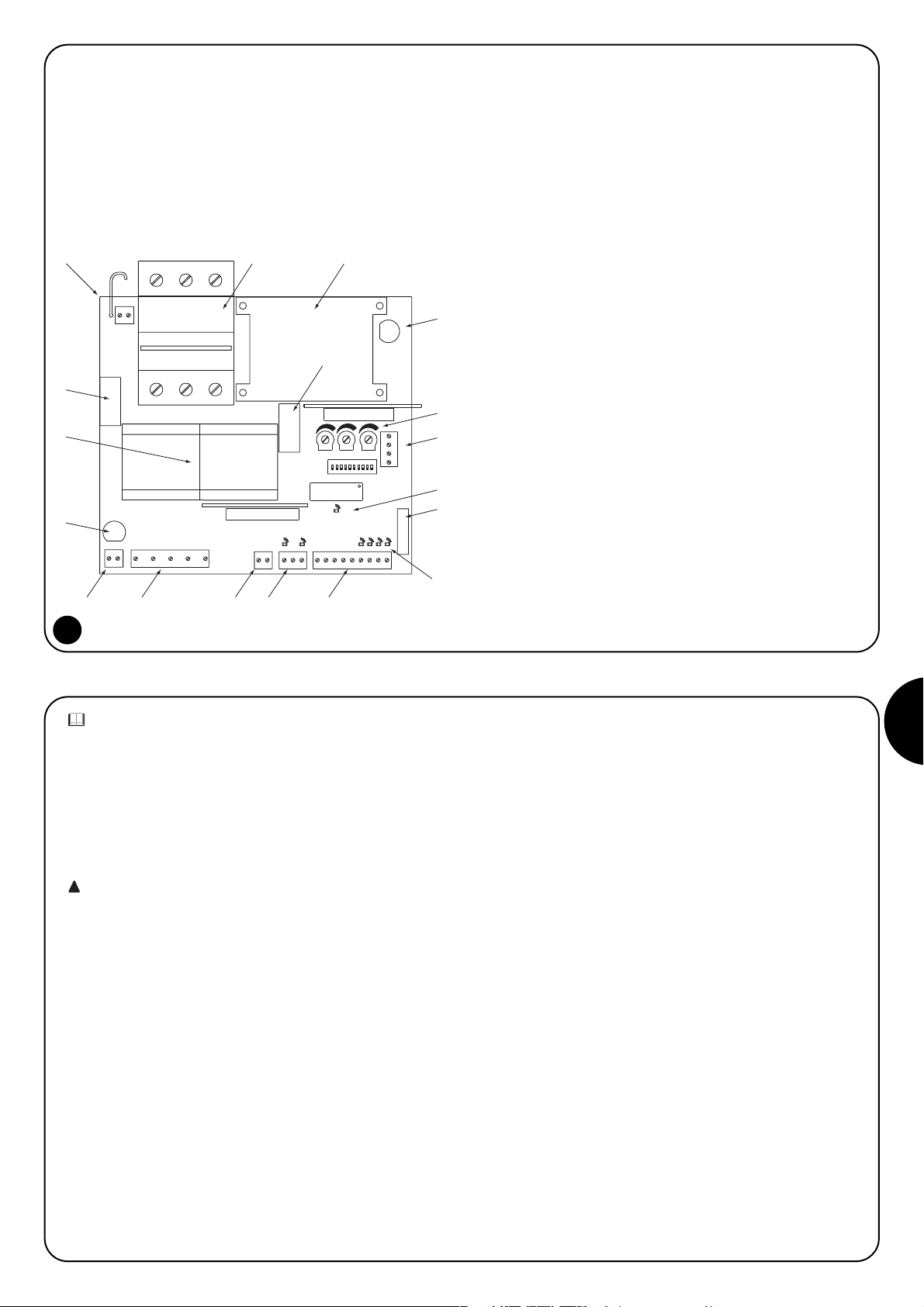
NL
63
R
Q
S
POMN
AP
CH
L
H
I
G
F
T
A
U
BC
D
E
TLM
F2= 0.5 A
"PIU"
OK
1
TPTL F
F1= 0.5 A
COM
RADIO
400
230
A Keuze stroomtoevoer 230 / 400V
B Magneethermische overbelastingsbeveiliging
C Transformator stroomtoevoer
D Zekering stroomtoevoer besturingseenheid (500mA)
E Afstellingstrimmer
F Klemmenbord radio
G Dipschakelaar voor het kiezen van de functies
H Ledlampje signalering OK
I Stekker voor instructies op de poort
L Ledlampje signalering status ingangen
M Klemmenbord Instructie-ingangen / Instructie-uitgangen
N Klemmenbord ingang eindschakelaar
O Klemmenbord uitgang Fototest
P Uitgang stroomtoevoer motor
Q Uitgang waarschuwingslicht
R Zekering waarschuwingslicht (500mA)
S Contactgevers manoeuvre motor
T Relais activering waarschuwingslicht
U Relais activering Rem
1) Beschrijving van het product:
Met deze besturingseenheid voor het automatiseren van automatische poorten en deuren kunt u een driefasen- of éénfase wisselstroommotor op 230V of 400V aansturen.
De besturingseenheid beschikt over technieken om obstakels waar
te nemen (antibeknelling) en een remsysteem dat inertie bij het stoppen reduceert.
Er zijn een aantal functies beschikbaar die met behulp van dipschakelaars (minischakelaars) geselecteerd kunnen worden, en bepaalde
afstellingen die met trimmers kunnen worden uitgevoerd.
In de besturingseenheid zijn er ledlampjes bij de ingangen die de
status daarvan aangeven; een ander ledlampje bij de microprocessor geeft aan of de interne logica correct functioneert.
2) Installeren:
Controleer alvorens met de installeringswerkzaamheden te beginnen of de poort sterk en mechanisch solide is en de veiligheidszones
evenals de minimumafstanden aangehouden zijn. Maak een zorgvuldige risico-analyse in relatie tot de automatisering, beoordeel uiterst
zorgvuldig de toe te passen veiligheidsinrichtingen
en installeer altijd een inrichting voor een noodstop. Verifieer zorgvuldig dat de “mechanische eindaanslagen” zonder de minste vervorming in staat zijn alle kinetische energie die zich tijdens de beweging
van de vleugel opgebouwd heeft, op te vangen en te absorberen.
Installeer de besturingseenheid niet alvorens eerst de nood-
zakelijke “Mechanische eindaanslagen” aangebracht zijn!
Behalve deze voorschriften die betrekking hebben op elektrische
apparatuur in het algemeen, de installaties van machines en automatische deuren en poorten, vermelden wij andere specifieke
opmerkingen voor deze besturingseenheid welke de installatie nog
veiliger en betrouwbaarder maken:
- De leiding van stroomtoeover naar de besturingseenheid moet
altijd beveiligd worden door een magneetthermische schakelaar of
door een stel zekeringen van 5A; een differentiaalschakelaar verdient
de voorkeur maar is niet onmisbaar indien die al vóór de installatie
gemonteerd is.
- Sluit de besturingseenheid met een kabel van 5 x 1,5mm
2
(3 fasen
+ nulleider + aarde) op het elektriciteitsnet aan; als de afstand tussen de besturingseenheid en de aansluiting op de installatie meer
dan 30 m bedraagt, dient u in de buurt van de besturingseenheid
voor aarding te zorgen.
- Bij aansluitingen in het gedeelte met zeer lage veiligheidsspanning
dient u kabeltjes met een minimumdoorsnede van 0,25mm
2
te
gebruiken.
Gebruik afgeschermde kabeltjes als de lengte meer dan 30m
bedraagt en aard het omhulsel alleen aan de zijde van de besturingseenheid.
- Gebruik enkel en alleen kabels (verschillende draden die apart geïsoleerd zijn plus een verdere algemene isolatie) en nooit afzonderlijke draden ook al zijn die in speciale kanaaltjes beschermd.
- Maak absoluut geen aansluitingen op kabels in dozen onder de
grond ook al zijn die helemaal waterdicht.
Vergewis u ervan dat u over al het nodige materiaal beschikt en dat
dit voor dit soort gebruik geschikt is.
Een juiste keuze bij het installeren van de besturingseenheid is van
fundamenteel belang voor een adequate veiligheid en een goede
bescherming tegen weersinvloeden. Denk eraan dat er in de besturingseenheid delen zijn waarop de spanning van het elektriciteitsnet
staat en elektronische componenten die op zich zelf bijzonder teer
zijn. De besturingseenheid wordt geleverd in een kastje dat wanneer
dat goed geïnstalleerd wordt, een beveiligingsgraad geeft die als
IP55 geclassificeerd is (volgens IEC 70-1 en IEC 529) en dus ervoor
geschikt is ook buiten geïnstalleerd te worden.
In ieder geval is het noodzakelijk onderstaande eenvoudige maar
fundamentele regels in acht te nemen:
- Installeer de besturingseenheid op een vaste ondergrond die volkomen vlak en adequaat schokbestendig waarbij u erop dient te letten dat
de onderzijde zich tenminste op 40 cm van de grond moet bevinden.
- Breng speciale kabelklemmen of doorvoerbuizen alleen in de
onderkant van de besturings-eenheid aan; om geen enkel reden
mogen er in de zijwanden of bovenwand boringen gemaakt worden.
De kabels mogen de besturingseenheid alleen van beneden af binnenkomen!
1
!
Page 64

64
A
2.2) Schema voor de aansluitingen:
Om bij de aansluitingswerkzaamheden van componenten of het
aanbrengen van de verschillende kaarten de veiligheid van de technicus te garanderen en schade aan de verschillende componenten
te voorkomen, geldt het volgende: De besturingseenheid mag
absoluut niet onder spanning staan.
Wij herinneren u er bovendien aan dat de ingangen van de contacten van het type Normaal gesloten (NC), indien niet gebruikt, via een
brug verbonden dienen te worden; als er voor dezelfde ingang meerdere contacten zijn, dan worden die onderling SERIEEL geschakeld.
De ingangen van de contacten van het type Normaal open (NO) dienen, indien niet gebruikt, onderling PARALLEL geschakeld te worden. Het is absoluut noodzakelijk dat het mechanische contacten
zijn en contacten zonder enige potentiaal; aansluitingen in fasen
zoals "PNP", "NPN", "Open Collector" etc. zijn niet toegelaten.
Alvorens een en ander te gaan aansluiten, dient u te controleren of
de gemaakte selectie overeenkomt met de spanning van de stroomtoevoer.
Een fout bij het selecteren hiervan kan ernistige schade voor de
componenten van de besturingseenheid ten gevolge hebben!
De afgebeelde tekening laat de aansluitingen van de besturingseenheid zien bij driefasen stroomtoevoer van 400 Volt.
Voor de aansluiting van de besturingseenheid met een éénfase of
driefasen stroomtoevoer met een spanning van 230 Volt gelieve u de
tekeningen op de afbeeldingen 3a en 3b te raadplegen.
N.B.:
Installerings- en onderhoudswerkzaamheden mogen alleen door gekwalificeerd en ervaren personeel uitgevoerd worden en wel conform de voorschriften van de Richtlijn 89/392 (Richtlijn machines) en met name EN 60204 (Elektrische uitrusting van de machines) volgens de beste aanwijzingen der “Regelen der kunst”.
2.1) Selectie spanning stroomtoevoer:
De besturingseenheid kan correct werken bij een stroomvoorziening driefasen of éénfase (zie aansluitingsschema) met
een spanning van 400V of 230V. Selectie van de spanning van de stroomtoevoer komt tot stand door een bruggetje dat
aangebracht dient te worden tussen het klemmetje “COM” en het klemmetje “230” of het klemmetje “400” zoals u op de
afbeelding kunt zien.
COM
230
400
2
COM
F2= 0,5 A
1
2
400
RTS
435
400 V
6
TLM
+
+
-
-
TPTL F
14
15
OK
16
17
"PIU"
7
9
8
10
11
12
13
-
18
19
20
+
44
43
42
41
ANTENA
2 Ch RADIO
21
UWV
LAMP.
230 Vac 40W
M
Max 200 mA
24 Vac
SCA
COM
24 Vac Max 200m
FCA
FOTOTEST
FCC
COM (24V)
3
ALT
P. P.
FOTO
AP
CH
400 V
Page 65

NL
65
230 V Éénfase
2.3) Beschrijving van de aansluitingen:
Alle aansluitingen komen via speciale klemmetjes op de onderzijde van
de elektronische kaart tot stand. Alleen de leiding voor de stroomtoevoer mag aan de bovenzijde binnenkomen, rechtstreeks op de klemmetjes van de magneetthermische overbelastingsbeveiliging. Om de
besturingseenheid en de motor te aarden gelieve u bij voorkeur de
klemmetjes 6-7 te gebruiken.
Indien de besturingseenheid door een éénfasesysteem gevoed wordt,
zullen slechts twee draden op de eerste twee klemmetjes links van de
magneetthermische overbelastingsbeveiliging aangesloten moeten
worden (het derde klemmetje zal ongebruikt blijven). De éénfasemotor
en de daarbijhorende condensator zullen daarentegen aangesloten
worden zoals u op afbeelding 3 kunt zien. Let ook goed op bij het kiezen van de spanning van de stroomtoevoer, 400V of 230V.
We geven hieronder een beknopte beschrijving van mogelijke externe aansluitingen van de besturingseenheid.
1-2 : Waarschuwingslicht = Aansluiting van het waarschuwingslicht 220 Vac max 40W
3-4-5 : Motor = Leiding naar de motor 230Vac / 400Vac
6-7 : Aarde = Aansluiting van de besturingseenheid en de motor op de aarde
8-9 : Fototest = Uitgang 24 Vac voor stroomtoevoer zenders van de fotocellen (Max 200mA)
10 : Fca = Ingang eindschakelaar OPENING
11 : Gemeenschappelijk = Gemeenschappelijk voor de ingangen eindschakelaars
12 : Fcc = Ingang eindschakelaar SLUITING
13-14 : 24 Vac = S
troomtoevoer neveninrichtingen 24 Vac (Foto, Radio, etc.) Max 200mA (400mA als de fototest niet gebruikt wordt)
15 : Gemeenschappelijk = Gemeenschappelijk voor alle ingangen
16 : Controlelampje C.A. = Controlelampje poort open 24 Vac max. 2W
17 : Stop = Ingang met functie van STOP (Noodstop, blokkering of extreme beveiliging)
18 : Foto = Ingang voor veiligheidsinrichtingen (Fotocellen, pneumatische randen)
19 : Stap-voor-stap = Ingang voor cyclische werking ( OPENING STOP SLUITING STOP )
20 : Opening = Ingang voor openingsmanoeuvre
21 : Sluiting = Ingang voor sluitingsmanoeuvre
41-42 : 2° Ch Radio = Uitgang voor een eventuele tweede kanaal van de radio-ontvanger
43-44 : Antenne = Ingang voor de antenne van de radio-ontvanger
Er zijn bovendien nog 2 insteekgleuven voor de volgende apart verkrijgbare kaarten:
RADIOKAART = Insteekgleuf voor de door NICE vervaardigde radio-ontvangers
KAART “PIU“ = Insteekgleuf voor de kaart “PIU” met supplementaire functies
Het verdient aanbeveling met het insteken van eventuele apart verkrijgbare kaarten RADIO of PIU te wachten tot nadat u met het installeren klaar bent. Apart verkrijgbare kaarten zijn niet noodzakelijk om de installatie te laten werken en maken, indien aangebracht, het opsporen
van eventuele defecten moeilijker.
Aansluiting van de besturingseenheid met een stroomtoevoer 230V éénfase
Aansluiting van de besturingseenheid met een stroomtoevoer 230V driefasen
Aansluiting van de besturingseenheid met een stroomtoevoer 400V driefasen
3b
3c
3a
LN
F2= 0.5 A
COM
230
230 V Éénfase
LN
COM
230
400 V Driefasen
RST
COM
400
1
2
230 Vac 40W
F2= 0.5 A
2
1
230 Vac 40W
F2= 0.5 A
1
2
230 Vac 40W
COM
U
U
3
AP
M
230 V
7
645
CH
3
4
V
M
230 V
7
6
5
W
3
V
M
400 V
7
645
W
Page 66

66
2.4) Opmerkingen ten aanzien van de aansluitingen:
Het merendeel van de aansluitingen is uiterst eenvoudig, voor een
groot deel betreft het rechtstreekse aansluitingen op één enkele
gebruikspunt of contact, andere daarentegen hebben een iets complexere aansluiting. Een nadere beschrijving verdient de uitgang
“Fototest”, dit is een uitstekende oplossing ten aanzien van de
betrouwbaarheid van de veiligheidsinrichtingen waardoor, voor wat
betreft de combinatie besturingseenheid en veiligheidsfotocellen,
"categorie 2" volgens de norm UNI EN 954-1 (uitgave 12/1998)
behaald kan worden. Telkens wanneer er een manoeuvre van start
gaat, worden alle veiligheids-inrichtingen in kwestie gecontroleerd en
alleen als de test een positief resultaat geeft, gaat de manoeuvre van
start. Als de test daarentegen geen positief resultaat heeft (kortsluiting kabels etc.) wordt de storing gedetecteerd en de manoeuvre
niet uitgevoerd. Dit alles is mogelijk door een configuratie in de aansluitingen van de veiligheidsinrichtingen toe te passen waarbij de
stroomtoevoer van de zenders van de fotocellen op de klemmetjes
8-9 aangesloten wordt, terwijl de stroomtoevoer van de ontvangers
op de uitgang van de neveninrichtingen (klemmetjes 13-14) opgenomen wordt. Wanneer er een bedieningsopdracht voor een
manoeuvre gegeven wordt, wordt er eerst nagegaan of alle ontvangers die met deze manoeuvre van doen hebben, hun ok geven;
daarna wordt de stroomvoorziening naar de zenders onderbroken
en wordt vervolgens gecontroleerd of alle ontvangers dit feit signaleren door hun ok in te trekken; tenslotte wordt de uitgang fototest
opnieuw geactiveerd en wordt opnieuw gecontroleerd of alle ontvanger hun ok geven. Het is raadzaam het synchronisme te activeren
door de bruggetjes op de zenders te doorbreken; dit is de enige
methode om ervoor te zorgen dat er tussen de twee stellen fotocellen
geen interferentie plaats vindt. Controleer in de handleiding van de
fotocellen de aanwijzingen voor gesynchroniseerde werking. Indien
een ingang FOTO niet wordt gebruikt (bijvoorbeeld FOTO2) en u toch
de functie fototest wilt, dient u een bruggetje aan te brengen tussen
de niet gebruikte ingang en het klemmetje 9 van de uitgang fototest.
Nadat de aansluitingen van de motor en de verschillende accessoires
tot stand zijn gekomen kunt u tot de eindtest van de installatie overgaan.
LET OP: Bij het uitvoeren van onderstaande handelingen
werkt u met onder spanning staande circuits. Op het merendeel van de circuits staat laagspanning en daar bestaat dus
geen gevaar, maar op sommige delen staat de spanning van
het elektriciteitsnet, die dus UITERST GEVAARLIJK zijn! Let
heel goed op wat u doet en WERK NOOIT ALLEEN!
Het is raadzaam met deze test te beginnen terwijl de besturingseenheid in “handbediende modus” staat en alle functies gedeactiveerd
zijn (dipschakelaar Off); bij eventuele problemen stopt bij handbediende modus de motor onmiddellijk wanneer de bedieningstoets
los gelaten wordt. Controleer ook dat alle afstellingstrimmers op het
minimum staan (tegen de wijzers van de klok in gedraaid); alleen de
trimmer “KRACHT” kan op het maximum gezet worden.
A) Ontgrendel de poort, breng hem halverwege en vergrendel hem
dan, op deze manier kan de poort vrijelijk bewegen, zowel bij
opening als bij sluiting.
B) Controleer of u op het klemmenbord links van de magneetther-
mische overbelastingsbeveiliging een juiste spanning van de
stroomtoevoer hebt geselecteerd.
C) Zet de besturingseenheid onder spanning en controleer meteern
dat er tussen de klemmetjes 13-14 en tussen de klemmetjes 8-9
een spanning van 24 Vac staat.
Zodra de besturingseenheid onder spanning komt te staan, moeten
de controlelampjes (LEDLAMPJES) die zich op de actieve ingangen
bevinden, gaan branden; bovendien moet binnen enkele ogenblikken het ledlampje “OK” regelmatig beginnen te knipperen.
Als dit allemaal niet gebeurt, dient u onmiddellijk de stroomvoorziening te onderbreken en de aansluitingen zorgvuldiger te controleren.
Het ledlampje “OK” in het midden van de kaart heeft tot taak de status van de interne logica aan te geven: regelmatig knipperen met een
ritme van 1 seconde geeft aan dat de interne microprocessor actief
is en op instructies wacht. Wanneer de micro-processor daarentegen een wijziging in de status van een ingang (zowel instructieingang als dipschakelaar van de functies) herkent, heeft dit een dubbele snelle knippering ten gevolge, ook als de wijziging geen onmiddellijke gevolgen heeft. Zeer snelle knipperingen gedurende 3 seconden geeft aan dat de besturingseenheid ojuist onder spanning gezet
is en een test op de interne delen aan het uitvoeren is; tenslotte
geven onregelmatige en niet-constante knipperingen aan dat de test
niet tot een goed einde is gekomen en dat er dus een storing is.
D) Vergewis u er nu van dat de ledlampjes horende bij de ingangen
met contacten van het type NC branden (alle veiligheidsinrichtingen actief) en dat de ledlampjes behorende bij de ingangen van
het type NO uit zijn (geen enkele bedieningsopdracht aanwezig);
indien dit niet het geval is dient u te controleren of de verschillende inrichtingen correct zijn aangesloten en goed werken.
E) Controleer of alle veiligheidsinrichtingen van de installatie (nood-
stop, fotocellen, pneumatische randen etc.) goed werken, telkens
wanneer die in werking treden, moeten de desbetreffende ledlampjes STOP of FOTO uitgaan.
F) Controleer de juiste aansluiting van de eindschakelaars; verplaats
de poort en controleer of wanneer u het gewenste punt hebt
bereikt, de eind-schakelaar in kwestie in werking treedt en het
overeenkomstige ledlampje op de besturingseenheid uit gaat.
G) Nu dient u te verifiëren of de manoeuvre in de juiste richting plaats
vindt, d.w.z. te controleren of de door de besturingseenheid
doorgegeven manoeuvre overeenkomt met de daadwerkelijk
door de vleugels uitgevoerde manoeuvre. Deze controle is van
fundamenteel belang; als de richting in bepaalde gevallen niet
juist is (bijvoorbeeld in de semi-automatische modus), zou het
automatisme schijnbaar regelmatig functioneren; de cyclus OPENING is immers gelijk aan de cyclus SLUITING met dat fundamentele verschil echter dat de veiligheidsinrichtingen genegeerd
zullen worden bij de sluitingsmanoeuvre - die normaal gesproken
3) Eindtest:
4
9
8
TX
TX
FOTO
FOTO 2
(kaart PIU)
RX
RX
18
15
PIU (10)
14
13
!
Page 67

NL
67
de gevaarlijkste is - en bij opening in werking zullen treden waar-
door ze een hersluiting tegen het obstakel zullen veroorzaken met
desastreuze gevolgen! Om te verifiëren of de draairichting juist is
behoeft u alleen maar een alleen maar een korte impuls op de
ingang Stap-voor-Stap te geven; de eerste manoeuvre die de
besturingseenheid uitoefent nadat ze onder spanning is gezet is
altijd de manoeuvre OPENING; dus behoeft u alleen maar te con-
troleren of de poort open gaat. Als de manoeuvre in de verkeerde
richting plaats vindt, gaat u als volgt te werk:
1 - Schakel de stroomtoevoer uit
2 - Bij de driefasenmotor trifase, wisselt u 2 van de 3 aansluitingen
van de motor om. Bij de éénfasemotor dient u de aansluitingen
“OPENING” en “SLUITING” van de motor om te wisselen.
Nadat u wat hierboven beschreven is uitgevoerd hebt, is het
raadzaam opnieuw te proberen of de draairichting correct is waarvoor
u de handelingen vanaf punt “G” opnieuw dient uit te voeren.
H) Test een complete manoeuvre van de poortopener: het is
raadzaam steeds in handbediende modus te werken terwijl alle
functies gedeactiveerd zijn. Beweeg de poort met behulp van de
instructie-ingangen tot het punt van opening; als alles goed is
verlopen, kunt u tot een sluitingsmanoeuvre overgaan en de poort
tot het eindpunt laten lopen.
I) Voer verscheidene openings- en sluitingsmanoeuvres uit om te
controleren or er eventueel defecten in de mechanische structuur
van de automatisering zijn en om te verifiëren of er punten met een
bijzondere wrijving bestaan.
L) Test of de veiligheidsinrichtingen FOTO bij de openings manoeuvre
geen enkel gevolg hebben; bij sluiting veroorzaken zij een
onderbreking van de manoeuvre. Als de kaart PIU' aanwezig is
dient u ook de werking van de ingang FOTO 2 te controleren, die
bij het sluiten geen enkel gevolg heeft, maar bij het openen de
manoeuvre onderbreekt. De op de ingang STOP aangesloten
inrichtingen werken zowel bij opening als sluiting en onderbreken
altijd de manoeuvre.
De besturingseenheid kent 3 afstellingen die via de afstellingstrimmers tot stand komen; deze wijzigen de onderstaande parameters:
Werkingsduur (TL):
Hiermee wordt de maximale tijdsduur van de openings- of sluitingsmanoeuvre afgesteld.
Pauzeduur (TP):
Bij "automatische" werking wordt met deze functie de tijd tussen het
einde van de openingsmanoeuvre en het begin van de sluitingsmanoeuvre afgesteld.
Kracht(F):
Hiermee kunt u de drempel voor inwerkingtreding van de stroommeting
afstellen. Voor het afstellen van de werkingsduur TL, selecteert u de werkingsmodus “Semi-automatisch” door de dipschakelaar 1 op ON te zetten en vervolgens de trimmer TL halverwege te zetten. Voer bij deze
afstellingen een openings en een sluitingscyclus uit en stel de trimmer TL
eventueel zodanig bij, dat er voldoende tijd is om de gehele manoeuvre
uit te voeren en er ook nog een zekere speling van 2 of 3 seconden overblijft. Indien er niet voldoende tijd is, ook al hebt u de trimmer TL op het
maximum gezet, dient u de brug TLM op de print tussen de trimmers
TL en TP te verbreken om de werkingstijd te verlengen. Voor het afstellen van de Pauzeduur TP selecteert u de werkingsmodus “Automatisch”
door de dipschakelaar 2, op ON te zetten en vervolgens stelt u de trim-
mer TP af, zoals u dat wenst. Om een en ander te controleren dient u
een openingsmanoeuvre uit te voeren en vervolgens de tijd te controleren die er verstrijkt voordat de poort weer automatisch gesloten wordt.
Speciale aandacht dient u te schenken aan de afstelling van de trimmer
KRACHT (F); deze afstelling kan van invloed zijn op de graad van veiligheid van de automatisering. Voor het afstellen hiervan dient u proefondervindelijk te werk te gaan bij het meten van de kracht die nodig is om
het systeem in werking te doen treden. Volg hiertoe ook de aanwijzingen die u in het volgende hoofdstuk vindt. Het afstellen vindt niet lineair
over de gehele amplitude van de trimmer plaats, maar is in slechts één
zone geconcentreerd, waardoor het kan gebeuren dat in het eerste deel
van de trimmer afstelling geen enkel gevolg heeft en dat u daarna
slechts eventjes de trimmer moet draaien om grote variates te verkrijgen.
De reden van deze weinig lineaire werking moet gezocht worden in de
noodzaak een goede werking te garanderen bij een uitgebreid gamma
motoren, zowel éénfase- als driefasenmotoren.
4) Afstellingen:
5) Detectiesysteem van obstakels:
Deze besturingseenheid is voorzien van een systeem voor het opsporen van obstakels, dat gebaseerd is op bepaalde technieken voor het
controleren van de kracht van de motor in functie van het door de
motor opgenomen vermogen. Deze techniek wordt algemeen
“stroommeting” genoemd en veroorzaakt een inversie of een onderbreking van de manoeuvre, al naar gelang de geprogrammeerde werkingsmodus. In deze besturingseenheid kan het controlesysteem op
twee manieren werken: “normaal” of “intelligent” die via dipschakelaar
8 geselecteerd kunnen worden (zie hoofdstuk “Programmeerbare
functies”). In de “normale” modus treedt het systeem in werking wanneer het door de motor opgenomen vermogen de met de trimmer
Kracht afgestelde drempel bereikt. Er is één niveau en dit heeft als
nadeel dat wanneer er meer vermogen opgenomen wordt, iets wat
aan veranderingen in de spanning, temperatuur of anderszins te wijten
is, het systeem ten onrechte in werking kan treden.
De “intelligente” modus is ontwikkeld om deze beperking te overwinnen.
Deze heeft de eigenschap het niveau waarop het systeem in werking
treedt aan te passen, behalve met het door de trimmer afge stelde punt
ook via een intelligente handeling die langzame veranderingen als
gevolg van de hierboven genoemde redenen te onderscheiden van de
snelle veranderingen welke door een obstakel veroorzaakt worden.
N.B.: Bij beide systemen is tijdens de beginfase van de manoeuvre
en voor een duur van 1,5 seconde de detectie van obstakels via
stroommeting niet actief.
Het afstellen van de kracht samen met andere voorzieningen moet
het mogelijk maken de recente Europese voorschriften prEN 12453:
veiligheid bij het gebruik van door motoren aangedreven deuren vereisten en indelingen; en prEN 12445: veiligheid bij het gebruik van door
motoren aangedreven deuren- testmethodes, in acht te nemen. Deze
normen vereisen het toepassen van maatregelen om de krachten bij
het aansturen van automatische deuren te beperken.
5
TLM
TPTL F
+
-
+
-
+
-
Page 68

68
6) Werkingsmodi:
Bij de werkingsmodus Handbediening kunt u met ingang OPENING
een openingsmanoeuvre uitvoeren en met de ingang SLUITING een
sluitingsmanoeuvre. De ingang STAP VOOR STAP maakt afwisselend een openings- en sluitingsmanoeuvre mogelijk.
Zodra de bedienings-opdracht op de ingang komt te vervallen, komt
de beweging tot stilstand. Bij opening komt de beweging tot stilstand wanneer de eindschakelaars in werking treden of als toestemming van FOTO2 (op de kaart PIU') ontbreekt; bij sluiting daarentegen wordt de manoeuvre onderbroken, ook als toestemming van
FOTO ontbreekt. Wanneer er, zowel bij een openings-als sluitingsmanoeuvre op STOP gedrukt wordt, veroorzaakt dit een onmiddellijke onderbreking van de manoeuvre. Zodra de poort niet meer loopt
dient u eerst de binnenkomende bedieningsopdracht te onderbreken alvorens een nieuwe manoeuvre te laten beginnen. Bij één van
de automatische werkingsmodi (Semi-automatisch - Automatisch en
Sluit altijd) veroorzaakt een bedieningsopdracht op de ingang OPENING een openingsmanoeuvre. Een impuls op STAP VOOR STAP
veroorzaakt afwisselend een openings- of sluitingsmanoeuvre. Een
tweede impuls op STAP VOOR STAP of op dezelfde ingang die de
manoeuvre gestart heeft, veroorzaakt een toestand van Stop. Zowel
bij een openings- als bij een sluitingsmanoeuvre zal een bedieningsopdracht op STOP ervoor zorgen dat de manoeuvre onmiddellijk
onderbroken wordt.
Als op een instructie-ingang in plaats van een impuls een voortdurend signaal gegeven wordt, ontstaat er een staat van “voorkeur”
waarbij de andere instructie-ingangen niet vrijgegeven zijn (nuttig
voor het aansluiten van een tijdschakelklok of een keuzeschakelaar
Nacht-Dag). Wanneer de automatische werkingsmodus geselecteerd is, heeft er na een openingsmanoeuvre een pauze plaats, na
afloop waarvan er een sluitings-manoeuvre wordt uitgevoerd. Als er
tijdens een pauze tussenkomst van FOTO plaatsvindt, zal de tijdschakelklok teruggesteld worden met een nieuwe pauzeduur; als er
daarentegen tijdens een pauze een bedieningsopdracht op STOP
gegeven wordt, zal de functie van een nieuwe sluiting gewist worden
en komt de poort in een toestand van STOP. Bij een openingsmanoeuvre heeft tussenkomst van de veiligheidsinrichtingen FOTO
geen enkel gevolg, terwijl FOTO2 (op de kaart PIU') omdraaiing van
de manoeuvre veroorzaakt; bij sluiting veroorzaakt tussenkomst van
FOTO omdraaiing van de manoeuvre, daarna een pauze en vervolgens opnieuw een sluiting.
De besturingseenheid beschikt over een serie microschakelaars
waarmee u de verschillende functies kunt activeren teneinde de
installatie zo goed mogelijk op de eisen van de gebruiker af te stemmen en bij de verschillende gebruikswijzen zo veilig mogelijk te
maken. Alle functies worden geactiveerd door de desbetreffende
dipschakelaar op de stand “On” te zetten, terwijl ze niet ingeschakeld zijn wanneer de desbetreffende dipschakelaar op “Off” staat.
LET OP: sommige programmeerbare functies hebben gevolgen
voor de veiligheidsaspecten; beoordeel zorgvuldig de gevolgen van
een bepaalde functie en controleer welke functie de grootst mogelijke zekerheid biedt.
Bij het onderhoud van een installatie dient u voordat u een programmeerbare functie gaat wijzigen, eerst te beoordelen waarom er
tijdens de installeringsfase bepaalde keuzes zijn gemaakt, en vervolgens na te gaan of bij een nieuwe programmering de veiligheid
afneemt.
7) Programmeren:
7.1) Programmeerbare functies:
Met behulp van de dipschakelaar FUNCTIES kunt u de verschillende werkingsmodi selecteren en de door u gewenste functies volgens
onderstaande tabel invoeren:
Schakelaar 1-2: Off-Off = Manoeuvre “Handbediening” d.w.z. er is iemand aanwezig
On-Off = “Semi-Automatische Manoeuvre”
Off-On = “Automatische Manoeuvre” d.w.z. Automatische Sluiting
On-On = “Automatische Manoeuvre + Sluit altijd”
Schakelaar 3: On = Werking Woonblok < Niet beschikbaar bij handbediende modus >
Schakelaar 4: On = Voorwaarschuwing
Schakelaar 5: On = Terugloop onmiddellijk na Foto < alleen bij automatische modus
Schakelaar 6: On = Veiligheidsinrichting Foto ook bij opening
Schakelaar 7: On = Fototest
Schakelaar 8: On = Intelligent systeem stroommeting
Schakelaar 9: On = Gedeeltelijke omkering bij inwerkingtreding systeem stroommeting < uitgesloten bij handbediende modus >
Schakelaar10: On = Rem
Op “Off” activeert geen enkele schakelaar de functie, op “On” daarentegen activeert die de beschreven functie.
Sommige functies zijn onder bepaalde omstandigheden mogelijk; deze zijn aangegeven met de opmerkingen tussen de tekens “<...>”.
6
on
1
off
Page 69

NL
69
7.2) Beschrijving van de functies:
Hieronder geven wij een beknopte beschrijving van de functies die ingeschakeld kunnen worden door de desbetreffende dipschakelaar op
"On" te zetten
Schakelaar 1-2: Off-Off = "Handbediende" manoeuvre (er is iemand aanwezig)
On-Off = “Semi-automatische Manoeuvre”
Off-On = “Automatische Manoeuvre” (Automatisch sluiting)
On-On = “Automatische Manoeuvre + Sluit altijd”
Bij de "Handbediende" modus wordt de manoeuvre alleen uitgevoerd zolang de instructie aanwezig is (toets ingedrukt). Bij "Semi-automatisch"
is een instructie-impuls voldoende en wordt de gehele manoeuvre uitgevoerd totdat de Werkingsduur verlopen is of de eindschakelaar bereikt
is. Bij "Automatische" werking is er na een openingsmanoeuvre een pauze waarna de sluiting automatisch uitgevoerd wordt. De functie "Sluit
altijd " treedt in werking na een storing in de stroomvoorziening, waarbij automatisch een sluitingsmanoeuvre uitgevoerd wordt na een voorwaarschuwing van 5 seconden, indien de poort open gevonden wordt.
Schakelaar 3: On = Werking Woonblok (niet beschikbaar bij werkingsmodus Handbediening)
Bij de functie Woningblok kan de manoeuvre, zodra de openingsmanoeuvre van start gegaan is, niet door andere bedieningsimpulsen op
STAP-VOOR-STAP of OPEN onderbroken worden zolang de openingsmanoeuvre nog niet beëindigd is.Tijdens een sluitingsmanoeuvre zal een
nieuwe bedieningsimpuls de poort laten stoppen en zal de poort weer open gaan.
Schakelaar 4: On = Voorwaarschuwing
Bij het ontvangen van een bedieningsimpuls wordt eerst het waarschuwingslicht geactiveerd en gaat vervolgens na 5 seconden (2 sec. bij
handbediening) de manoeuvre van start.
Schakelaar 5: On = Terugloop 5 seconden na Foto (alleen bij de automatische modus)
Met behulp van deze functie kunt u de poort zolang openhouden als nodig is om te passeren; nadat FOTO in werking is gekomen, zal er altijd
een sluiting plaats vinden na een pauze van 5 seconden, onafhankelijk van de afgestelde Pauzeduur.
Schakelaar 6: On = Veiligheidsinrichting (Foto) ook bij opening
Normaal gesproken is de veiligheidsinrichting Foto alleen tijdens de sluitingsmanoeuvre geactiveerd; als de schakelaar 6 op "On" wordt gezet,
zal de veiligheidsinrichting ook bij opening de manoeuvre onderbreken. Bij de Semi-automatische of Automatische modus zal de manoeuvre,
zodra de veiligheidsinrichting vrijkomt, weer hervat worden.
Schakelaar 7: On = Fototest
Hiermee kunt u voor het begin van een manoeuvre een testfase van de fotocellen laten uitvoeren; op deze manier verhoogt u de veiligheid van
de installatie voor wat betreft het geheel van besturingseenheid + fotocellen, zodat de “categorie 2” volgens de norm UNI EN 954-1 (uitgave
12/1998) behaald wordt. Om deze functie te kunnen gebruiken dienen de fotocellen aangesloten te worden zoals dat op het schema op afbeelding 4 te zien is.
Schakelaar 8: On = Intelligente stroommeting
Met deze functie kunt u de modus van de te gebruiken stroommeting selecteren. Als de schakelaar op “Off” is gezet, is de normale stroommeting actief, terwijl als deze op “On” is gezet, de intelligente stroommeting actief is.
Schakelaar 9: On = Gedeeltelijke omkering wegens inwerkingtreding van de stroommeting < uitgesloten bij Handmatige modus >
Wanneer het systeem van stroommeting in werking treedt, volgt er gewoonlijk een omkering van de manoeuvre; als de schakelaar op “On”
staat, loopt de poort gedurende 1,5 seconde terug en daarna zal de manoeuvre onderbroken worden.
Schakelaar 10: On = Rem
Met deze functie kunt u de inertie van de vleugel aan het einde van de manoeuvre verminderen. Gedurende 1 seconde krijgt de motor zoveel
stroom dat een snelle onderbreking van de manoeuvre gewaarborgd wordt ook bij automatiseringen met een grote opgebouwde kinetische
energie.
Page 70

70
8) Toepassing van 2 besturingseenheden op tegenovergestelde vleugels:
Voor het aanleggen van een automatisering die bestaat uit 2 vleugels
die in tegenovergestelde richting werken, dient u twee besturingseenheden te gebruiken die aangesloten dienen te worden zoals dat op de
afbeelding hieronder is weergegeven. De motoren en eindschakelaars
moeten elk op hun eigen besturingseenheid aangesloten worden, terwijl het waarschuwingslicht eb het controlelampje Poort Open kunnen
op één van de twee, onverschillig welke, worden geïnstalleerd of desgewenst één per besturingseenheid. Als u de functie fototest gebruikt
dient u de uitgang van één enkele besturingseenheid te gebruiken.
De ingangen dienen onderling parallel geschakeld te worden.
“Gemeenschappelijk” kan op één van de twee besturingseenheden
aangesloten worden.
Verbind de twee 0Volt (Klemmetje 13) van de twee besturingseenheden met elkaar.
Het is raadzaam de functie “Woonblok” (dipschakelaar 3) in te schakelen waarmee de vleugels weer synchroon gemaakt kunnen worden
indien de 2 besturingseenheden niet meer synchroon werken.
AP
CH
"PIU"
FOTO
ALT
Max 200 mA
24 Vac
SCA
COM (24V)CHAP
P. P.
18
13151417162119
20
24 Vac Max 200mA
8
9
FCC12COM11FCA
10
FOTOTEST
5
4
3
6
7
VUWCH
AP
COM
230 V
400 V
2
1
LAMP.
230 Vac 40W
42
41
44
43
RADIO
COM
230
400
F2= 0.5 A
F1= 0.5 A
400 V230 V
TL TP F
OK
TLM
230 Vac 40W
LAMP.
FCA
COM
FCC
24 Vac
Max 200 mA
400 V
230 V
21
F2= 0.5 A
2
1
7
6
3
4
5
101112
9
8
20
19161714151318
COMAPCHW
V
U
OK
"PIU"
AP
CH
TPTL
F1= 0.5 A
RADIO
TLM
COM
400
230
230 V 400 V
42
41
44
43
F
9) Apart verkrijgbare accessoires:
- kaart “PIU”
De besturingseenheid bevat reeds alle functies die in een normale installatie gebruikt worden; om aan de gebruikseisen in bijzondere installatie
tegemoet te komen is een apart verkrijgbare kaart “Kaart PIU” ontworpen waarmee nieuwe functies toegevoegd kunnen worden, zoals signalering door verkeerslicht, gebruikerslicht, Elektroslot, Foto2, gedeeltelijke
opening etc.
- kaart “RADIO”
In de besturingseenheid bevindt zich een insteekgleuf voor het aanbrengen van een door Nice vervaardigde radiokaart waarmee u de
ingang STAP VOOR STAP kunt gebruiken en zo de besturingseenheid op afstand via een zender kunt aansturen.
7
Page 71

NL
71
10) Onderhoud:
De kaart als elektronisch onderdeel vereist geen enkel bijzonder
onderhoud. Verifieer in ieder geval periodiek, tenminste twee maal per
jaar, of de aansturingsinrichting van de stroombeveiliging van de
motoren perfect werkt en stel dat zo nodig met de afsteltrimmers bij.
Controleer of de veiligheidsinrichtingen (fotocellen, pneumatische randen, etc.) juist functioneren en het waarschuwingslicht correct werkt.
10.1) Informatie over de maatregelen ter bescherming van
het milieu:
Dit product bestaat uit verschillende soorten materialen waarvan
sommige opnieuw gebruikt kunnen worden.
Win inlichtingen in ten aanzien van de systemen voor hergebruik of
afvalverwerking van het product en houd u aan de plaatselijk geldenden voorschriften en wetten.
10.2) Technische gegevens van de besturingseenheid:
Stroomtoevoer via de elektriciteitsleiding : 400 Vac of 230 Vac ± 10%, 50 of 60Hz
Max. stroom op de motoren : 4A
Uitgang neveninrichtingen : 24Vac maximale stroom 200mA (400mA indien fototest niet gebruikt)
Uitgang fototest : 24Vac maximale stroom 200mA
Uitgang waarschuwingslicht : Voor waarschuwingslichten 230Vac, maximumvermogen 40 W
Uitgang controlelampje poort open “CPO” : Voor controlelampjes 24Vac, maximumvermogen 2 W
Werkingsduur : Instelbaar van <3 tot >120 s, of van <90 tot>210 s bij TLM
Pauzeduur : Instelbaar van <5 tot>200 s
Bedrijfstemperatuur : -20 ÷ 70 °C
Page 72

Declaration of conformity
Declaration of Conformity
Dichiarazione CE di conformità secondo Direttive 73/23/CEE, 89/336/CEE
CE Declaration of Conformity according to Directives 73/23/CEE, 89/336/CEE
Numero 112/A500 Revisione: 1
Number Revision
Il sottoscritto Lauro Buoro in qualità di Amministratore Delegato, dichiara sotto la propria responsabilità che il prodotto:
The undersigned Lauro Buoro, managing director, declares under his sole responsibility that the following product:
Nome produttore: NICE s.p.a.
Manufacturer’s name
Indirizzo Via Pezza Alta 13, 31046 Z.I. Rustignè, Oderzo (TV) Italia
Address
Tipo Centrale per comando motori scorrevoli 230Vac / 400Vac
Type 230Vac / 400Vac sliding motors control unit
Modello A500
Models
Accessori: Ricevente radio SMXI, SMXIS; batteria di emergenza PS124
Accessories SMXI, SMXIS radio receiver; PS 124 buffer battery
Risulta conforme a quanto previsto dalle seguenti direttive comunitarie, così come modificate dalla Direttiva 93/68/CEE del
consiglio del 22 Luglio 1993:
The product complies with the specifications of the following EC directives, as amended by the directive, 93/68/EEC of the European Council of 22ndJuly 1993:
73/23/CEE; DIRETTIVA 73/23/CEE DEL CONSIGLIO del 19 febbraio 1973 concernente il riavvicinamento delle legislazioni
degli Stati membri relative al materiale elettrico destinato ad essere adoperato entro taluni limiti di tensione.
Secondo le seguenti norme armonizzate: EN 60335-1.
73/23/EEC DIRECTIVE 73/23/EEC OF THE COUNCIL of February 19, 1973 for the harmonisation of the legislations of member States regarding electrical equipment designed to be used within certain voltage limits.
In compliance with the following harmonised standards: EN 60335-1.
89/336/CEE; DIRETTIVA 89/336/CEE DEL CONSIGLIO del 3 maggio 1989, per il riavvicinamento delle legislazioni degli Stati
membri relative alla compatibilità elettromagnetica.
Secondo le seguenti norme armonizzate: EN 61000-6-2; EN 61000-6-3.
89/336/EEC DIRECTIVE 89/336/EEC OF THE COUNCIL of May 3, 1989, for the harmonisation of the legislations of member States regarding electromagnetic compatibility.
In compliance with the following harmonised standards: EN 61000-6-2; EN 61000-6-3
Oderzo, 15 Febbraio 2005
Oderzo, 2 Febbraryr 2005 Amministratore Delegato
Managing Director
Lauro Buoro
ISTA500.4858 REV. 01 del 28-02-2005
Nice SpA
Oderzo TV Italia
Tel. +39.0422.85.38.38
Fax +39.0422.85.35.85
info@niceforyou.com
Nice Padova
Sarmeola di Rubano PD Italia
Tel. +39.049.89.78.93.2
Fax +39.049.89.73.85.2
infopd@niceforyou.com
Nice Roma
Roma Italia
Tel. +39.06.72.67.17.61
Fax +39.06.72.67.55.20
inforoma@niceforyou.com
Nice France
Buchelay
Tel. +33.(0)1.30.33.95.95
Fax +33.(0)1.30.33.95.96
Nice Rhône-Alpes
Decines Charpieu France
Tel. +33.(0)4.78.26.56.53
Fax +33.(0)4.78.26.57.53
Nice France Sud
Aubagne France
Tel. +33.(0)4.42.62.42.52
Fax +33.(0)4.42.62.42.50
Nice Belgium
Leuven (Heverlee)
Tel. +32.(0)16.38.69.00
Fax +32.(0)16.38.69.01
info@be.niceforyou.com
Nice España Madrid
Tel. +34.9.16.16.33.00
Fax +34.9.16.16.30.10
info@es.niceforyou.com
Nice España Barcelona
Tel. +34.9.35.88.34.32
Fax +34.9.35.88.42.49
info@es.niceforyou.com
Nice Polska
Pruszków
Tel. +48.22.728.33.22
Fax +48.22.728.25.10
info@pl.niceforyou.com
Nice UK
Chesterfield
Tel. +44.87.07.55.30.10
Fax +44.87.07.55.30.11
info@uk.niceforyou.com
Nice China
Shanghai
Tel. +86.21.575.701.45/46
Fax +86.21.575.701.44
info@cn.niceforyou.com
www.niceforyou.com
Nice Gate is the doors and gate automation division of Nice Nice Screen is the rolling shutters and awnings automation division of Nice
 Loading...