

Page 1

control units
mindy A400
Istruzioni ed avvertenze per l’installatore
Instructions and warnings for the fitter
Instructions et recommandations pour l’installation
Anweisungen und hinweise für den installateur
Instrucciones j advertencias para el instalador
Instrukcja dla instalatora
Page 2

mindy A400
Avvertenze:
This manual has been especially written for use by
qualified fitters. No information given in this manual can be
considered as being of interest to end users!
This manual refers to the A400 control unit and may not be
used for different products.
The A400 control unit has been designed to control electromechanical
actuators for automated swing gates or doors; any other use is
considered improper and is consequently forbidden by current laws.
Do not install the unit before you have read all the instructions at least
once.
!
Table of contents: pag.
1 Product description 3
2 Installation 3
2.1 Preliminary checks 3
2.2 Fixing the A400 control unit 4
2.3 Typical system layout 4
2.4 Electrical connections 4
2.4.1 Electrical diagram 5
2.4.2 Description of connections 5
2.4.3 Notes on connections 6
2.4.4 Phototest 6
2.4.5 Checking connections 7
2.5 Searching for mechanical stops 7
2.5.1 Automatic searching 8
2.5.2
Searching with the current sensitivity device disabled
8
3 Programmable functions 9
3.1 Pre-set functions 9
pag.
4 Programming 10
4.1 Memory deletion 10
4.2 Programming methods 10
4.2.1 Level one programming: functions 11
4.2.2 Level two programming: parameters 11
4.2.3 Example of level one programming 12
4.2.4 Example of level two programming 12
4.2.5 Programming diagram 13
5 Testing 14
6 Optional accesories 14
7 Servicing the A400 control unit 14
7.1 Disposal 14
8 What to do if ... 15
9 Technical specifications 15
Annex:
SMXI Radio receiver 16
Page 3

3
GB
The A400 control unit operates on the basis of a system (current
sensitivity) which checks the load of the motors that are connected
to it. This system automatically detects the travel stops and
recognises obstacles during normal movement (anti-crush safety
feature).
This feature makes installation very simple given that no adjustments
need to be made.
The control unit is pre-programmed for normal functions while more
specific functions can be chosen following a simple procedure.
The level of current also depends on other factors apart from load, e.g.:
voltage variations, the type of motor, the value of the starting capacitor, etc…
The A400 control unit has been optimised for the motors used in the Wingo
actuators, other types of motor may cause the A400 control unit to work
incorrectly.
ABCDEFG H
I
L
M
N
OPQRS
T
A Primary transformer connector
B Common relay
C Open/Close relay
D M1 motor relay
E M2 motor relay
F Very low voltage fuse (500mA)
G Secondary transformer connector
H Microprocessor
I Radio receiver connector
L Phototest relay
M “INPUTS” Led
N “OK” Led
O Terminal for radio aerial
P Programming buttons
Q Input-output terminals
R Terminals for motors and flashing light
S Power input terminals
T Line fuse (5A)
In order to protect the operator and the electronic
card from accidental damage, only the control unit
terminal boards and programming buttons are normally
accessible.
Only remove the cover if necessary and always disconnect
the mains power supply beforehand.
!
1) Product description:
Automatic gate and door systems may only be
installed by qualified fitters in the full respect of the law.
Comply with the warnings shown in the “Warnings for
fitters” file.
!
2.1) Preliminary checks
Before starting installation make sure that all the material is suitable
for installation and complies with legal requirements. As well as
checking all the points shown in the “Warnings for fitters” file, this
section also contains a specific check list for the A400 control unit.
• The “mechanical stops” must be able to stop the gate from moving
and must absorb all the kinetic energy accumulated during
movement without difficulty.
• Power the control unit using a 3 x 1.5 mm2 cable.
Should the distance between the control unit and the earth
connection exceed 30 m, install an earth plate near the control
unit.
• Use wires with a minimum cross section of 0.25 mm2 to connect
low voltage safety circuits.
Use shielded wire if the length exceeds 30 m and connect the
earth braid only on the control unit side.
• Do not connect cables in buried boxes even if they are completely
watertight.
• If correctly installed, the control unit is protected to IP55 and can
therefore be installed outdoors.
Fix the control unit on a permanent surface that is perfectly flat and
adequately protected against knocks, making sure that the
bottom remains at least 40 cm from the ground.
• Only fit cable holders or pipe leads in the lower part of the
container (see figure 1, figure 1a).
2) Installation:
Page 4

4
2.3) Typical system layout
In order to explain certain terms and aspects of an automatic 2-leaf
swing door or gate system, we will now illustrate a typical system
layout.
In particular, please note that:
• All the photocells produced by NICE feature the SYNCHRONISM
system which eliminates the problem of interference between two
pairs of photocells (please consult the photocell instructions for
further details).
• The “PHOTO” pair of photocells have no effect during opening
while they invert movement during closing.
• The “PHOTO1” pair of photocells stops both the opening and
closing manoeuvres.
• The “PHOTO2” pair of photocells (connect to the suitably
programmed AUX input) have no effect during closing while they
invert movement during opening.
2.2) Fixing the A400 control unit
The container is fitted with a cover which protects the electronic
board from accidental contact.
Only touch the board when necessary by proceeding as shown in
figure 1a.
To make it easier to make holes in the lower part of the container,
lower the plastic bottom as shown in figure 1a, ref. 1.
2.4) Electrical connections
To protect the fitter and avoid damaging the
components while electrical connections are being made
or the radio receiver is being connected, under no
circumstances may the unit be electrically powered.
• If the inputs of the NC (Normally Closed) contacts are not used
they should be jumped with the “24V Common” terminal (except
for the photocell inputs; for information please see the
PHOTOTEST function).
• If there is more than one NC contact on the same input, they must
be connected in SERIES.
• If the inputs of the NO (Normally Open) contacts are not used they
should be left free.
• If there is more than one NO contact on the same input, they must
be connected in PARALLEL.
• The contacts must be mechanical and potential-free; no stage
connections are allowed, such as those defined as "PNP", "NPN",
"Open Collector", etc..
• The starting condenser is built into the WINGO motors.
!
1 1a
PHOTO
1
PHOTO
PHOTO 2
6
7
1
1
4
2
3
5
1.Elettromechanical actuators
2.Flashing lamp
3.“A400” control unit
4.Key switch
5.“PHOTO” pair of photocells
6.“PHOTO1” pair of photocells
7.“PHOTO2” pair of photocells
ref. 1
Page 5

5
GB
2.4.1) Electrical diagram
1
LN
M1 M2
2
5 6 7 8 9 101112 1314 151617181920212223
24 25
34
P1
ALT
LED OK
P2
PP
POWER SUPPLY
FLASHING LAMP
AERIAL
COMMON 24 V
24V
0
0
24V (TX PHOTO)
SCA 24Vac
STOP (NC)
PHOTO (NC)
PHOTO 1 (NC)
STEP-BY-STEP (NO)
AUX (NO)
PHOTOTEST
24Vac
2.4.2) Description of connections
A brief description of the possible control unit output connections follows
Terminals Functions Description
1÷3 Power input Mains power supply
4 Earth Motor earth connection
56 Flashing lamp Connection of flashing lamp to mains voltage (max. 40W)
7÷9 Motor 1 * M1 motor connection (lower leaf)
10÷12 Motor 2 * M2 motor connection (upper leaf)
13÷14 Phototest TX photocell power output (24Vac max. 100mA)
15÷16 24 Vac Power output for services, RX photocells, etc. (24Vac max. 150mA)
17 Common 24 Vac Common for all inputs/outputs
18 SCA Gate open indicator (24Vac max. 1.5W)
19 Stop Input NC with STOP function (emergency, safety shutdown)
20 Photo Input NC for safety devices (photocells, pneumatic edges)
21 Photo1 Input NC for safety devices (photocells, pneumatic edges)
22 Step-by-Step Input for cyclical functioning (OPEN STOP CLOSE STOP)
23 AUX ** Auxiliary input
24÷25 Aerial Input for the radio receiver aerial
* With 2 motors, the first to move in the opening cycle is the M2 motor.
The A400 control unit automatically recognises if there is just one motor installed which must be connected to M2.
** The auxiliary input AUX may be programmed in one of these functions (see chapter 4 “Programming”):
Function Input type Description
PARTIAL OPEN type 1 NO Completely opens the leaf connected to the M2 motor
PARTIAL OPEN type 2 NO Opens the 2 leafs halfway
OPEN NO Only carries out the open manoeuvre
CLOSE NO Only carries out the close manoeuvre
PHOTO 2 NC PHOTO 2 function
DISABLED -- No function
Unless otherwise programmed, the AUX input performs the PARTIAL OPEN type 1 function
OPEN
COMMON
CLOSE
OPEN
COMMON
CLOSE
WARNING: Connection of photocells with Phototest (see chapter 2.4.4)
Note: pre-programmed control unit set for automatic measuring of working time (see chapter 2.5.1)
Page 6

6
Most connections are extremely simple; many of them are direct
connections to a single user point or contact.
The following figures show examples of how to connect external
devices.
2.4.3) Notes about connections
12345
12345
12345
12
12
12
LED OK
TX
PHOTO
PHOTO 1
PHOTO 2
RX
TX RX
TX RX
13
P1 P2 24 25
14 15 16 17 18 19 20 21 22 23
13
TX
PHOTO
1 123452
LED OK
P1 P2 24 25
RX
14 15 16 17 18 19 20 21 22 23
The PHOTOTEST function is a standard feature on the A400
control unit. This is an excellent solution as regards the reliability of
safety devices and puts the control unit and safety devices into
“category 2” as per UNI EN 954-1 standard (ed. 12/1998).
Whenever a manoeuvre is begun, the relative safety devices are
checked and only if everything is in order will the manoeuvre start. All
this is only possible if a special configuration of the safety device
connections is used; in practice, the “TX” photocell transmitters are
powered separately from the “RX” receivers.
The SYNCHRONISM function (available on all NICE photocells) is the
only way of ensuring that two pairs of photocells do not interfere with
each other.
The inputs subject to the phototest procedure are PHOTO, PHOTO1 and
the AUX input if configured as PHOTO2. The Phototest phase takes place at
the beginning of each manoeuvre and cannot be disabled; therefore, if one of
these inputs is not used, it must be connected to terminal n°13, please
consult the following figures for examples of connections.
2.4.4) Phototest
Slow flashing means the gate is
opening.
Fast flashing means the gate is
closing
Lamp permanently on means the
gate is open.
Photo, photo1 and photo2 connection diagram.
Connection diagram with just the PHOTO photocell
Example 1
How to connect the switch in
order to perform the STEP-BYSTEP and STOP functions.
Example 2
How to connect the switch in
order to perform the STEP-BYSTEP function and one of the
auxiliary input functions
(PEDESTRIAN, OPEN ONLY,
CLOSE ONLY…).
Example of connection for a 24Vac
powered external radio.
Channel 1
➔
STEP-BY-STEP
Channel 2
➔
AUX
Gate open indicator connection
C
onnections for an external radio
Key switch connection
2 3
STEP BY
STEP
COM
STOP
COM
24V
17
18
1,5W
1
15
16
22
17
23
12
24V
0V
2345612
NA NC
17
22
19
17
STEP BY
STEP
COM COM
NA NA
17
22
23
17
AUX
Page 7

7
GB
Examples of single-wire photocell connections
Connecting the PHOTO photocell only.
(ref. fig. 2)
N.B.: The PHOTO1 (21) input is not used and must therefore be
connected to terminal 13 in order to allow the PHOTOTEST function
to work exclusively with PHOTO.
PHOTO and PHOTO1 connections
N.B.: observe the indicated power input connections and enable the
SYNCHRONISM function (available on all the NICE photocells).
PHOTO, PHOTO1 and PHOTO2 connections
(ref. fig. 3)
N.B.: observe the indicated power input connections and enable the
SYNCHRONISM function (available on all the NICE photocells).
12345
12
TX
PHOTO
RX
13
14
13
15
16
17
20
21
12345
12
12345
12
PHOTO
PHOTO
1
TX RX
TX RX
13
14
14
13
15
16
17
20
16
15
17
21
12345
12
12345
12
12345
12
PHOTO
TX RX
PHOTO 1
TX RX
PHOTO 2
TX RX
13
14
14
13
14
13
15
16
17
20
16
15
17
21
16
15
17
23
2.4.5) Checking connections
The next operations involve work being done on live
circuits, some parts have mains voltage running through
them and are therefore EXTREMELY DANGEROUS! Pay the
greatest of attention to what you are doing and NEVER
WORK ALONE!
After making connections, the whole system must be checked.
• Power the control unit and check that all the Leds flash rapidly for
a few seconds.
• Check that terminals 1-2 are powered and that voltage is about
24Vac on terminals 15-16; if this is not the case, unplug the unit
immediately and carefully check the connections and input
voltage.
• After the initial rapid flashing, the “OK” Led shows the control unit
is working correctly by flashing regularly at 1 second intervals.
When there is a variation in the inputs, the “OK” led flashes rapidly
twice to show that the input has been recognised.
• If the connections are correct, the relative Led on the NC inputs,
i.e. STOP, PHOTO and PHOTO1 must be on. The STEP-BY-STEP
and AUX Leds must be off (if PHOTO2 and AUX are present and
programmed correctly, the AUX Led must be on).
• Make sure that the relative Leds switch on and off when the
devices connected to the inputs are operated.
!
STOP Photo Photo1Step
by
Step
AUX
STOP PP
P1 P2
2.5) Searching for mechanical stops
After these checks have been made the control unit can be made to
automatically search for the mechanical stops; this operation is
required as the A400 control unit must “measure” the duration of the
opening and closing manoeuvres.
If the control unit has never been installed, i.e. there is no valid duration in
its memory, the procedure is activated automatically. If this procedure has
already been carried out, in order to reactivate it, the memory must first be
deleted (see the “Memory programming – deletion” chapter). To find out
whether the memory contains duration data, switch power to the unit off and
on. If all the Leds flash rapidly for 10 seconds, the memory is empty; if they
flash for just 3 seconds, the memory already contains motor work times.
Page 8

8
2.5.2) Searching with the current sensitivity
device disabled
If the current sensitivity device does not work correctly, the control
unit can work to timed cycles, totally excluding the current sensitivity
function. (to disable the current sensitivity system, see the
“Programming parameters and functions” section).
In this case the fitter “tells” the control unit when the mechanical stop
has been reached.
• Before beginning searching with the current sensitivity device
disabled, make sure that all the safety devices are enabled (STOP,
PHOTO and PHOTO1 active).
• The doors should preferably be about half open but they may be
in any position.
• Press the PP button to begin the searching phase,
comprising:
– Brief opening, first M2 and then M1.
If the motors do not start during the opening cycle or if the first to
move is not M2, press STOP to interrupt the search and check the
motor connections.
– Motor M1 closes until the closing mechanical stop is reached.
• Press PP when M1 reaches the closing mechanical stop.
– Motor M2 closes until the closing mechanical stop is reached.
• Press PP when M2 reaches the closing mechanical stop.
– After a few moments the M2 motor begins the opening cycle.
• Press PP when M2 reaches the opening mechanical
stop.
– After a few moments the M1 motor begins the opening cycle.
• Press PP when M1 reaches the opening mechanical
stop.
– After a few moments a complete closing cycle begins.
The motors can start at different times, the aim is to prevent the leafs
from shearing by maintaining a suitable delay.
– End of the procedure with memorisation of all time measurements.
All these phases must take place one after the other; the fitter must
only press PP when required. If procedure does not continue
correctly, press the STOP button to interrupt it. The procedure will be
immediately interrupted if a safety device triggers or a command
arrives.
2.5.1) Automatic searching
This procedure is completely automatic and detects the
mechanical opening and closing stops by measuring the load on
the motors.
In “particularly difficult” automated systems, the system for detecting
the variations in motor current may not work correctly; try changing the
current sensitivity device cut-in level or else revert to exclusively timed
operation; see the “Search with current sensitivity device disabled”
section.
• Before beginning automatic searching, make sure that all the safety
devices are enabled (STOP, PHOTO and PHOTO1 active). The
procedure will be immediately interrupted if a safety device triggers
or a command arrives.
• The doors should preferably be about half open but they may be
in any position.
• Press the PP button to begin the searching phase,
comprising:
– Motors open briefly, first M2 and then M1.
If the motors do not start during the opening cycle or if the first to
move is not M2, press STOP to interrupt the search and check the
motor connections.
– Motor M1 closes until the closing mechanical stop is reached.
– Motor M2 closes until the closing mechanical stop is reached.
– Motor M2 begins opening.
– After the programmed delay, motor M1 begins opening.
If the delay is not sufficient, press STOP to interrupt the search and
modify the time (see the “Programming” chapter).
– Measurement of the time required for the motors to reach the
opening mechanical stops.
– Complete closing manoeuvre.
The motors can start at different times, the aim is to prevent the leafs
from shearing by maintaining a suitable delay.
– End of the procedure with memorisation of all time measurements.
All these phases must take place one after the other without any
interference from the operator. If this does not happen, the
procedure will not continue correctly and must be interrupted with
the STOP button. Check the connections and then repeat the
procedure, modifying the current sensitivity cut-in thresholds if
necessary (see the “Programming” chapter).
STOP PP
P1 P2
P1 P2
STOP PP
Page 9

9
GB
Several functions and parameters of the A400 control unit can be
programmed to make the system more suitable to user needs and
safer in the various conditions of use.
“Automatic” function:
This function features an automatic closing cycle after the
programmed pause time; the pause time is factory set to 20
seconds but it can be modified to 5, 10, 20, 40 or 80 seconds.
“Condominium” function:
This function is useful when the automatic system is radiocommanded by many people. If this function is active, each
command received triggers an opening manoeuvre that cannot be
interrupted by further commands except for emergency / safety
impulses (STOP, PHOTO 1, PHOTO 2) followed by an immediate
closing manoeuvre (AUX configured to “Close only”).
Pre-flashing:
This function activates the flashing light before the manoeuvre begins
for a time that can be programmed to 2, 4, 6, 8 or 10 seconds.
Close 4 seconds after photo:
During the automatic closing cycle, this function reduces the pause
time to 4 seconds after the PHOTO photocell is disengaged, i.e. the
gate closes 4 seconds after the user has passed through.
Leaf delay:
During the opening cycle, this function activates the M1 motor at a
set time after M2 in order to prevent the doors from getting caught
up in each other. This delay is always used in the closing cycle
(required by safety regulations) and is automatically calculated by the
control unit in order to obtain the same programmed delay for the
opening cycle.
Current sensitivity:
The control unit features a system which measures the current
absorbed by the two motors and uses this to detect the mechanical
stops and any obstacles during gate movement. Given that the
absorbed current depends on variable conditions (weight of gate,
various kinds of friction, gusts of wind, voltage variations, etc.), the
cut-in threshold can be changed.
There are 5 levels: 1 is the most sensitive, 5 is the least sensitive. It
is factory set at level 2, a value that should be fine for most
installations.
Auxiliary input AUX:
The control unit has an auxiliary input that can be configured in one
of the following functions:
• Type 1 partial opening: this has the same function as the
STEP-BY-STEP input, i.e. it starts motor M2 only.
It only works if the gate is completely closed, otherwise it is
interpreted as a STEP-BY-STEP command.
• Type 2 partial opening: this has the same function as the
STEP-BY-STEP input, i.e. it opens the two leafs half the total
programmed time. It only works if the gate is completely closed,
otherwise it is interpreted as a STEP-BY-STEP command.
• Open only: this input carries out the opening manoeuvre only
using the Open-Stop-Open-Stop sequence.
• Close only: this input carries out the closing manoeuvre only
using the Close-Stop-Close-Stop sequence.
• Photo 2: performs the function of the “PHOTO 2” safety device.
• Disabled: the input has no function.
The operating principle of the current sensitivity
device is based on variations in the current absorbed by
the motors; if at the start of the manoeuvre the motor is
blocked because the leaf is already at the mechanical
stop, there will be no variation in current and the obstacle
will therefore not be detected.
If the “current sensitivity” function (together with
other vital features) is suitably adjusted, the system will
comply with European standards, EN 12453 and EN
12445, which require techniques or devices to be used to
limit force and danger when automatic gates and doors
are moved.
If conditions make it necessary, the current sensitivity function can be
disabled and the control unit can work to timed cycles only, see the
“Searching with the current sensitivity device disabled” chapter.
If the current sensitivity function is disabled, the
motors continue at “full force” for the whole manoeuvre.
Make a careful risks analysis and fit other safety elements
to the system, if necessary, to reach the safety levels
envisaged by law.
!!!
3) Programmable functions
3.1) Pre-set functions
The A4000 control unit features some programmable functions (see
the “Programmable functions” chapter) after the search phase.
These are initially pre-set in a typical configuration which satisfies
most automatic systems.
• Automatic closing : after 20 seconds
• Leaf delay : 4 seconds
• Pre-flashing : disabled
• Auxiliary input : type 1 partial opening
(motor M2 active only)
• Current sensitivity : Level 2
These functions can be changed at any time, both before and after
searching, by carrying out a suitable programming procedure.
Page 10

10
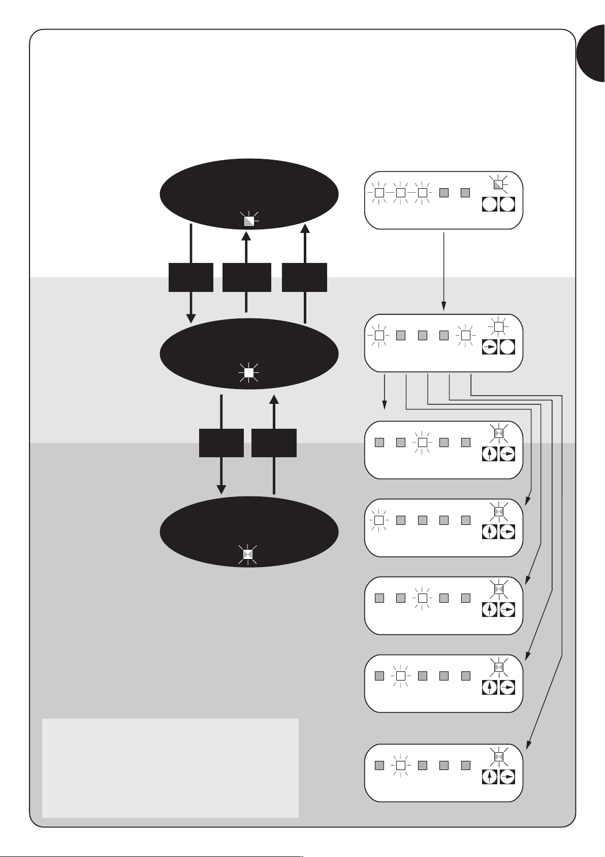
4.2) Programming methods
Just the two P1 and P2 buttons on the card are used for all
programming phases
In this case, the 5 “INPUT” Leds normally indicating the status of the
inputs show the selected “parameter”.
Example:
There are two different programming levels:
• At level 1, the functions can be activated or deactivated. Each
INPUT Led corresponds to a function: if the Led is on, the function
is active; if it is off, it is deactivated.
Led 1 : “Automatic” function
Led 2 : “Condominium” function
Led 3 : Pre-flashing
Led 4 : Close after photo
Led 5 : Opening delay
• It is possible to switch from level 1 to level 2 where the function
parameters can be chosen, each Led corresponds to a different
value to associate with the parameter.
4.1) Delete memory
Each new programme replaces the previous settings, normally it is
not necessary to “delete all” the memory.
If required, the memory can be totally deleted by performing this
simple operation:
After deleting the memory, a new search must be
made for the mechanical stops, while all the functions
return to their pre-set values.
!
Level 1:
Led 1 Led 2 Led 3 Led 4 Led 5
“Automatic”“Condominium” Pre-flashing Close 4 seconds Opening delay
function function after photo
Level 2:
Parameter: Parameter: Parameter: Parameter: Parameter:
Pause time AUX input Pre-flashing time Current Delay
sensitivity
L
ed 1 : 5s Led 1 : Type 1 partial opening Led 1 : 2s Led 1 : Level 1 Led 1 : 2s
Led 2 : 10s Led 2 : Type 2 partial opening Led 2 : 4s Led 2 : Level 2 Led 2 : 4s
Led 3 : 20s Led 3 : Open only Led 3 : 6s Led 3 : Level 3 Led 3 : 6s
Led 4 : 40s Led 4 : Close only Led 4 : 8s Led 4 : Level 4 Led 4 : 8s
Led 5 : 80s Led 5 : Photo 2 Led 5 : 10s Led 5 : Level 5 Led 5 : 10s
Leds off: Leds off:
input disabled current sensitivity disabled
Level 1 = most sensitive
Level 5 = least sensitive
All the functions described in the “Programmable functions” chapter
can be selected by means of a programming phase which
terminates by memorising the choices made.
The control unit therefore has a memory which stores the functions
and parameters relative to the automation process.
4) Programming
3s
Table “A1” Delete memory: Example
1. Disconnect the power supply
2. Press and hold down buttons P1 and P2 on the card
3. Connect the power supply
4. Wait for at least 3 seconds before releasing the two keys
N.B.: if the memory was deleted correctly, all the Leds will switch off for 1 second.
12345
P1 P2
P2P1
P2P1
In this case the
"Automatic", the preflashing and motor M1
opening delay functions
are active.
Page 11

11
GB
3s or 60s,
or
P1
3s
3s
1. Enter level one programming Press (pressing P1 and P2 for at least 3 seconds)
2. Select the function by pressing P1 until the flashing Led reaches the desired point
3. Enter level two by pressing the P2 button for at least 3 seconds
3s or 60s,
or
1. Press P1 for at least 3 seconds, or wait 1 minute,
or disconnect the power supply
4.2.1) Level one programming: functions
At level one, the functions can be activated or deactivated.
At level one, the OK Led is always on, the INPUT Leds indicate
which functions are active and which are not.
The flashing Led indicates which function is selected, if the Led
flashes quickly the function is disabled, if it flashes slowly, the
function is enabled.
3s
Table “B1” Entering level one programming: Example
1. Press and hold down buttons P1 and P2 for at least 3 seconds
The programming mode has been entered if all the Leds start flashing quickly
3s
1. Press P1 repeatedly until the flashing Led reaches the desired function
2. Press P2 to activate or deactivate the function. If the Led flashes quickly
the function is disabled, if it flashes slowly, the function is enabled.
Table “B3” Exiting level one and saving modifications: Example
1. Press and hold down buttons P1 and P2 for at least 3 seconds
Table “B4” Exiting level one and cancelling modifications: Example
1. Press P1 for at least 3 seconds, or wait 1 minute,
or disconnect the power supply
P2P1
P2P1
P1
P2
Table “B2” Activating or deactivating a function: Example
Table “C5” Exiting level one and cancelling modifications: Example
(also level two modifications)
P2P1
4.2.2) Level two programming: parameters
At level two the function parameter can be chosen. Level two can
only be reached from level one.
At level 2 the OK Led flashes quickly while the INPUT Leds
indicate the selected parameter.
Table “C1” Entering level two programming: Example
Table “C2” Selecting the parameter: Example
1. Press P2 repeatedly until the Led reaches the desired parameter
Table “C3” Returning to level one: Example
1. Press P1
3s
Table “C4” Exiting level one and saving modifications: Example
(also level two modifications)
1. Press and hold down buttons P1 and P2 for at least 3 seconds
P2P1
P1
P2
P1
P2
P1
Page 12

12
3s
x3
x1
3s
Example of level one programming: Example
activate the “Close after photo” function and deactivate “Opening delay”
1. Enter level one programming by pressing P1 and P2 for at least 3 seconds
2. Press P1 three times to move the flashing Led to the INPUT N°4 Led
(now it flashes quickly)
3. Press 2 to activate the “Close after photo” function
(now the Led flashes slowly)
4. Press P1 once to move the flashing Led to the INPUT N°5 Led
(now it flashes slowly)
5. Deactivate the “opening delay” function by pressing P2
(now the Led flashes quickly)
6. Press P1 and P2 for at least 3 seconds to exit the programming
mode and save modifications
4.2.3) Example of level one programming
These examples show how to activate or deactivate a level one
function, for example, how to activate the “Close after photo”
function and deactivate the leaf “Opening delay”.
3s
x3
3s
x4
3s
Example of level two programming: Example
modifying “current sensitivity”
1. Enter level one programming by pressing P1 and P2 for at least 3 seconds
2. Press P1 three times until the flashing Led reaches the INPUT N°4 Led
3. Press P2 for at least 3 seconds to shift to level 2
4. Press P2 4 times until all the INPUT Leds are off (current sensitivity disabled)
5. Press P1 to return to level one
6. Press P1 and P2 for at least 3 seconds to exit the programming
mode and save modifications
4.2.4) Example of level two programming
This example shows how to modify a level two parameter, for
example, how to modify and disable current sensitivity.
P2P1
P2P1
P1
4
P1
5
P2
P2P2P2
P2P1
P2P1
P1
4
P1
Page 13
13
GB
STOP Photo Photo1Step
by
Step
AUX
STOP PP
Auto Cond. Pre-
flashing
Close
after
photo
Leaf
delay
Normal
operation
OK Led
slow flashing
Level one
OK Led
permanently on
Level two
OK Led
rapid flashing
51020
seconds
40 80
PAUSE TIME
type 1
p.o.
type 2
p.o.
only
opening
only
closing
Photo 2
AUXILIARY IMPUT (*)
246
seconds
810
PRE-FLASHING TIME
1
All Leds off ➡ current sensitivity disabled
23
degree
45
CURRENT SENSITIVITY
246
seconds
810
MOTOR 1 DELAY
P1+P2
for 3 secs
P1
for 3 secs
(no save)
P1+P2
for 3 secs
(save)
P2
for 3 secs
P1
P1 P2
P1 P2
P1 P2
P1 P2
P1 P2
P1 P2
1
2
P1 P2
on
off
4.2.5) Programming diagram
The following figure shows the complete programming diagram of
the functions and relative parameters.
This figure also shows the functions and parameters as they were
initially or following total memory deletion.
(*)
type 1 p.o. type 1 partial open,
only motor 2 moves [N.O.]
type 2 p.o. type 2 partial open
both motors move for 1/2 the work time [N.O.]
only open open
➔ sto ➔ open ➔ stop … … [N.O.]
only close close
➔ stop ➔ close ➔ stop … … [N.O.]
photo 2 used as photo 2 [n.c.]
Page 14

14
The automation system must be tested by qualified
and expert staff who must establish what tests to perform
according to the relative risk.
Testing is the most important part of the whole installation phase.
Each single component, e.g. motors, radio receiver, emergency
stop, photocells and other safety devices, can require a specific test
phase; please follow the procedures shown in the respective
instructions manuals.
To test the control unit, carry out the following procedure (the
sequence refers to the A400 control unit with pre-set functions).
• Make sure that the activation of the STEP-BY-STEP input
generates the following sequence of movements: Open, Stop,
Close, Stop.
• Make sure that the activation of the AUX input (type 1 partial
opening function) only manages the Open, Stop, Close, Stop
sequence of motor 2 while motor 1 remains in the closed position.
• Engage each of the photocells or the other safety devices
connected to the PHOTO, PHOTO1 and PHOTO2 inputs and
make sure that no manoeuvres are made when a command input
is activated
• Perform an opening manoeuvre and check that:
– the gate continues the opening manoeuvre when PHOTO is
engaged.
– the manoeuvre stops when PHOTO1 is disengaged and only
continues when PHOTO1 is disengaged.
– the manoeuvre stops when PHOTO2 (if installed) is engaged and
the closing manoeuvre starts.
• Make sure that the motor switches off when the door reaches the
mechanical stop.
• Perform a closing manoeuvre and check that:
– The manoeuvre stops when PHOTO is engaged and the opening
manoeuvre starts.
– the manoeuvre stops when PHOTO1 is disengaged and the
opening manoeuvre starts when PHOTO1 is disengaged.
– The gate continues the closing manoeuvre when PHOTO2 is
engaged.
• Make sure that the stopping devices connected to the STOP input
immediately stop all and any movement.
• Check that the level of the obstacle detection system is suitable for
the application.
– During both the opening and the closing manoeuvres, prevent the
leaf from moving by simulating an obstacle and check that the
manoeuvre inverts before the force indicated by law is exceeded.
• Other checks may be required depending on what devices are
connected to the inputs.
If an obstacle is detected for 2 consecutive manoeuvres in the same
direction, the control unit partially inverts both motors for just 1 second.
At the following command, the leafs begin the opening manoeuvre and the
first current sensitivity cut-in for each motor is considered as stopping during
the opening cycle. The same thing happens when the mains power supply is
switched on: the first command is always an opening manoeuvre and the first
obstacle is always considered as stopping during the opening cycle.
!
5) Testing
The A400 control unit is an electronic component and therefore
needs no particular maintenance. Periodically check, however, at
least twice a year, that the whole system is in perfect working order
as indicated in the “Testing” chapter.
7) Servicing the A400 control unit
7.1) Disposal
This product is made from various kinds of material, some of which
can be recycled.
Make sure you recycle or dispose of the product in compliance with
current laws and bye-laws.
Some electronic components may contain polluting
substances; do not dump them.
!
6) Optional accessories
RADIO card
The control unit features a connector for plugging in an SM radio card , which activates the “Step-by-Step” and “Aux2” inputs and allows the
control unit to be remote-controlled through a transmitter.
output 1 STEP-BY-STEP
output 2 AUX2
output 3 not used
output 4 not used
Page 15

15
GB
9) Technical specifications
Power input : A400 control unit ➔ 230 Vac ±10% 50÷60Hz
: A400/V1 control unit ➔ 120 Vac ±10% 50÷60Hz
Maximum motor current : A400 control unit ➔ 1.2 A (with rotor locked)
: A400/V1 control unit ➔ 2.5 A (with rotor locked)
Service power output : 24 Vac maximum current 150mA
Phototest output : 24 Vac maximum current 100mA
Flashing lamp output : for flashing lamp at mains voltage, maximum power 40 W
Gate open indicator output : for indicator lamps at 24 Vac, maximum power 1.5 W
Work time : maximum 60 seconds
Pause time : programmable at 5, 10, 20, 40, 80 seconds
Leaf delay in open cycle : programmable at 2, 4, 6, 8, 10 seconds
Pre-flashing time : programmable at 2, 4, 6, 8, 10 seconds
Operating temperature: : -20 ÷ 50 °C
Container protected to : IP 55
Dimensions and weight : 230 x 180 h 100 mm, approx. 1100 g
This section will help fitters to solve some of the most common
problems that may arise during installation.
No Led is on:
• Check whether the control unit is powered (measure mains voltage
at terminals 1-2 and a voltage of 24Vac at terminals 15-16).
• Check the 2 fuses, if not even the OK Led is on or flashing a
serious fault has probably occurred and the control unit should
therefore be replaced.
The OK Led flashes regularly but the INPUT Leds do not
reflect the state of the respective inputs
• Switch off the unit for a moment in order to exit a possible
programming phase.
• Carefully check the connections on terminals 13 to 23.
The “Automatic search” procedure does not start.
• The “Automatic search” procedure only starts if it has never been
performed before or if the memory has been deleted. To check
whether the memory is empty switch off the unit for a moment;
when it is switched on again, all the Leds should flash rapidly for
10 seconds. If they flash for only 3 seconds, the memory already
contains valid values. If a new “Automatic search” is required, the
memory must be totally deleted.
The “Automatic search” procedure has never been
performed but it does not start or it behaves incorrectly
• To activate the “Automatic search” procedure the system and all
the safety devices must be operative, especially the photocells as
they are connected to the “phototest” phase.
• Make sure that no device connected to the inputs cuts in during
the “Automatic search” procedure.
• For the “Automatic search” procedure to start correctly, the input
Leds must be on as shown, the OK Led must flash once a
second.
The “Automatic search” procedure was performed
correctly but the manoeuvre does not start
• Check that the safety device (STOP, PHOTO, PHOTO1 and, if
installed, PHOTO2) Leds are on and that the relative command
Led (STEP-BY-STEP or AUX) remains on for the whole duration of
the command.
The gate inverts the direction while moving
An inversion is caused by:
• The photocells triggering (PHOTO2 during the opening manoeuvre,
PHOTO or PHOTO1 during the closing manoeuvre); in this case,
check the connections of the photocells and check the input
Leds.
• The current sensitivity device triggering while the motors are
moving (not near the mechanical stops, therefore); this is
considered as an obstacle and causes an inversion. To find out if
the current sensitivity device has triggered, check the OK Led: 1
rapid flash (compared with normal flashing of 1 second) indicates
that the current sensitivity device triggered on account of motor
M1, 2 rapid flashes indicate that this was caused by motor M2.
8) What to do if ...
STOP Photo Photo1Step
by
Step
AUX
STOP PP
P1 P2
Page 16

smxi radio receiver
Description of the product
The special thing about this type of radio receiver is that the
recognition code is different for each transmitter (it also changes
every time it is used).
Therefore, in order to allow the receiver to recognise a determined
transmitter, the recognition code must be memorised. This operation
must repeated for each transmitter required to communicate with the
control unit.
Up to a maximum of 256 transmitters can be memorised in the receiver.
No one transmitter can be cancelled; all the codes must be deleted.
- For more advanced functions use the appropriate programming unit.
During the transmitter code memorisation phase, one of these
options may be chosen:
Mode I. Each transmitter button activates the corresponding output
in the receiver, that is, button 1 activates output 1, button 2 activates
output 2, and so on. In this case there is a single memorisation phase
for each transmitter; during this phase, it doesn’t matter which button
is pressed and just one memory sector is occupied.
Mode II. Each transmitter button can be associated with a particular
output in the receiver, e.g., button 1 activates output 2, button 2
activates output 1, and so on. In this case, the transmitter must be
memorised, pressing the required button, for each output to activate.
Naturally, each button can activate just one output while the same
output can be activated by more than one button. One memory
section is occupied for each button.
Installing the aerial
The receiver requires an ABF or ABFKIT type aerial to work properly;
without an aerial the range is limited to just a few metres. The aerial
must be installed as high as possible; if there are metal or reinforced
concrete structures nearby you can install the aerial on top. If the
cable supplied with the aerial is too short, use a coaxial cable with 50Ohm impedance (e.g. low dispersion RG58), the cable must be no
longer than 10 m.
If the aerial is installed in a place that is not connected to earth
(masonry structures), the braid’s terminal can be earthed to provide a
larger range of action. The earth point must, of course, be local and
of good quality. If an ABF or ABFKIT aerial cannot be installed, you
can get quite good results using the length of wire supplied with the
receiver as the aerial, laying it flat.
16
Page 17

Memorising a remote control
When the memorisation phase is activated, any
transmitter correctly recognised within the reception
range of the radio is memorised. Consider this aspect with
care and remove the aerial if necessary to reduce the
capacity of the receiver.
The procedures for memorising the remote controls must be
performed within a certain time limit; please read and understand the
whole procedure before starting.
In order to carry out the following procedure, it is necessary to use the
button located on the box of the radio receiver (reference A, Fig. 1b),
and the corresponding LED (reference B, Fig. 1b) to the left of the
button.
3s
2s
x3
2s
x3
1. Press and hold down the receiver button for at least 3 seconds
2. Release the button when the Led lights up
3.
Within 10 seconds press the 1st button on the transmitter to be memorised,
holding it down for at least 2 seconds
N.B.: If the procedure was memorised correctly, the Led on the receiver will flash 3 times.
If there are other transmitters to memorise, repeat step 3 within another 10 seconds
The memorisation phase finishes if no new codes are received for 10 seconds.
Table “B1” Mode I memorising Example
(each button activates the corresponding output in the receiver)
1. Press and release the receiver button as many times as the number of the
desired output (twice for output no. 2)
2.
Make sure the Led flashes as many times as the number of the desired
output (2 flashes for output no. 2).
3.
Within 10 seconds press the desired button on the transmitter to be memorised,
holding it down for at least 2 seconds.
N.B.: If the procedure was memorised correctly, the Led on the receiver will flash 3 times.
If there are other transmitters to memorise, repeat step 3 within another 10 seconds
The memorisation phase finishes if no new codes are received for 10 seconds.
Table “B2” Mode II memorising Example
(each button can be associated with a particular output)
RX
RXTXTX
RX
1b
x5s
1s 1s 1s
x1
1. Press the button on the NEW transmitter for at least 5 seconds and then release
2. Press the button on the OLD transmitter 3 times slowly
3. Press the button on the NEW transmitter slowly and then release
N.B.: If there are other transmitters to memorise, repeat the above steps for each new transmitter
Table “B3” Remote Memorising Example
TX
TXTXTX
TX
TX
Remote memorising
It is possible to enter a new transmitter in the receiver memory
without using the keypad. A previously memorised and operational
remote control must be available. The new transmitter will “inherit”
the characteristics of the previously memorised one. Therefore, if the
first transmitter is memorised in mode I, the new one will also be
memorised in mode I and any of the buttons of the transmitter can
be pressed. If the first transmitter is memorised in mode II the new
one will also be memorised in mode II but the button activating the
required output must be pressed on the first transmitter as must the
button required to be memorised on the second. You need to read all
the instructions in advance so you can perform the operations in
sequence without interruptions. Now, with the two remote controls
(the NEW one requiring code memorisation and the OLD one that is
already memorised), position yourself within the operating range of
the radio controls (within maximum range) and carry out the
instructions listed in the table.
17
GB
Page 18

FLOR VERY VR FLO VERY VE SMILO
Buttons 1 – 2 - 4 2 1 – 2 - 4 2 2 - 4
Power input 12Vdc Batt. 23A 6Vdc lithium batt. 12Vdc Batt. 23° 6Vdc lithium batt. 12Vdc Batt. 23A
Absorption 10mA 10mA 15mA 10mA 25mA
Frequency 433.92MHz
Working temp. -40°C ÷ + 85°C
Radiated power 100µW
Deleting all transmitters
All the memorised codes can be deleted as follows:
x3
3°
x5
1. Press the receiver button and hold it down
2. Wait for the Led to light up, then wait for it to switch off
and then wait for it to flash 3 times
3. Release the button exactly during the third flash
N.B.: if the procedure was performed correctly, the Led will flash 5 times after a few moments.
Receivers
Transmitters
Table “B4” Deleting all transmitters Example
RX
RX
SMXI SMXIS SMXIF
Decoding Rolling code Rolling code 1024 FLO combinations
52 bit FLOR 64 bit SMILO
Frequency 433.92MHz
Input impedance 52ohm
Outputs 4 (on connector SMXI)
Sensitivity better than 0.5µV
Working temp. -20°C ÷ + 50°CC
Technical characteristics
18
Page 19

Dichiarazione CE di conformita’ / EC declaration of conformity
Numero /Number : 151/SMXI Data / Date: 09/2002 Revisione / Revision: 1
Il sottoscritto Lauro Buoro, Amministratore Delegato, dichiara che il prodotto:
The undersigned Lauro Buoro, General Manager of the following producer, declares that the product:
Nome produttore / Producer name:
NICE s.p.a.
Indirizzo / Address: Via Pezza Alta 13, 31046 Z.I. Rustignè –ODERZO- ITALY
Tipo / Type: Ricevitore radio 433MHz / Radio receiver 433MHz
Modello / Model: SMXI, SMXIS, SMXIF
Soddisfa tutti i requisiti essenziali applicabili alla direttiva R&TTE5/99, articolo 10.3.
Satisfies all the technical regulations applicable to R&TTE5/99 directive, article 10.3.
Risulta conforme a quanto previsto dalle seguenti Norme armonizzate / Complies with the following Harmonised standards
Riferimento n° Edizione Titolo norma
Livello di valutazione
Reference n° Issue Regulation title Assessment level
ETS300683 1997 Radio Equipment and Systems (RES);Electromagnetic Compatibility (EMC) standard for Classe II
Short Range Devices (SRD) operating on frequencies between 9KHz and 25GHz
EN300220-3 2000 APPARATI RADIO E SISTEMI Classe I (LPD)
CARATTERISTICHE TECNICHE E METODI DI MISURA PER APPARATI RADIO TRA
25MHz A 1000MHz/Radio Equipment and Sistems- Short Range Devices-Technical
characteristics and test methods for radio equipment between 25MHz and 1000 MHz
REGOLAZIONE ALL’USO DEI DISPOSITIVI A CORTO RAGGIO/Regolating to the use of
short range devices (SRD)
EN60950 2nd ed. 1992 APPARECCHIATURE PERLA TECNOLOGIA DELL’INFORMAZIONE. SICUREZZA.
+A1: 1993 + A2: 1993 + A3: 1995 + A4: 1997 + A11: 1997 + EN41003/1993.
Il prodotto suindicato si intende parte integrante di una delle configurazioni di installazione tipiche, come riportato nei nostri cataloghi generali
The above mentioned product is meant integral part of the of one of the installation configuration as shown on our general catalogues
ODERZO, 30 September 2002 (Amministratore Delegato)
(General Manager)
Lauro Buoro
19
GB
Nice reserves the right to modify the products whenever it sees fit.
Page 20

20
mindy A400
Avvertenze:
Il presente manuale è destinato solamente al personale
tecnico qualificato per l'installazione. Nessuna informazione
contenuta nel presente fascicolo può essere considerata
d’interesse per l'utilizzatore finale!
Questo manuale è riferito alla centrale A400 e non deve
essere utilizzato per prodotti diversi.
La centrale A400 è destinata al comando di attuatori elettromeccanici per
l'automazione di cancelli o porte ad ante battenti, ogni altro uso è
improprio e quindi vietato dalle normative vigenti.
Si consiglia di leggere attentamente tutte la istruzioni, almeno una volta,
prima di procedere con l’installazione.
!
Indice: pag.
1 Descrizione del prodotto 21
2 Installazione 21
2.1 Verifiche preliminari 21
2.2 Fissaggio centrale A400 22
2.3 Impianto tipico 22
2.4 Collegamenti elettrici 22
2.4.1 Schema elettrico 23
2.4.2 Descrizione dei collegamenti 23
2.4.3 Note sui collegamenti 24
2.4.4 Fototest 24
2.4.5 Verifica dei collegamenti 25
2.5 Ricerca arresti meccanici 25
2.5.1 Ricerca automatica 26
2.5.2 Ricerca con amperometrica esclusa 26
3 Funzioni programmabili 27
3.1 Funzioni pre-impostate 27
pag.
4 Programmazione 28
4.1 Cancellazione della memoria 28
4.2 Modalità di programmazione 28
4.2.1 Programmazione primo livello: funzioni 29
4.2.2 Programmazione secondo livello: parametri 29
4.2.3 Esempio di programmazione primo livello 30
4.2.4 Esempio di programmazione secondo livello 30
4.2.5 Schema per la programmazione 31
5 Collaudo 32
6 Accessori Opzionali 32
7 Manutenzione della centrale A400 32
7.1 Smaltimento 32
8 Cosa fare se….33
9 Caratteristiche tecniche 33
Appendice:
Ricevitore radio SMXI 34
Page 21

Il funzionamento della centrale A400 è basato su un sistema
(amperometrica) che verifica lo sforzo dei motori ad essa collegati.
Questo sistema permette di rilevare automaticamente i finecorsa e di
riconoscere eventuali ostacoli durante il normale movimento
(protezione antischiacciamento).
Questa caratteristica rende semplicissima l’installazione visto che non
serve nessuna regolazione.
La centrale è pre-programmata sulle funzioni normalmente richieste,
eventualmente attraverso una semplice procedura si possono
scegliere funzioni più specifiche.
L’andamento della corrente dipende anche da altri fattori oltre che dallo
sforzo, ad esempio: variazioni di tensione, il tipo di motore, il valore del
condensatore di spunto ecc… La centrale A400 è stata ottimizzata per i motori
presenti negli attuatori Wingo, altri tipi di motori potrebbero provocare un
funzionamento non corretto della centrale A400.
ABCDEFG H
I
L
M
N
OPQRS
T
21
I
A Connettore primario trasformatore
B Relè Comune
C Relè Apre/Chiude
D Relè motore M1
E Relè motore M2
F Fusibile bassissima tensione (500mA)
G Connettore secondario trasformatore
H Microprocessore
I Innesto per ricevitore radio
L Relè per fototest
M Led “INGRESSI”
N Led “OK”
O Morsetto per antenna radio
P Pulsanti per programmazione
Q Morsetti per ingressi-uscite
R Morsetti per motori e lampeggiante
S Morsetti per collegamento linea
T Fusibile di linea (5A)
Per proteggere l’operatore e la scheda elettronica da
manomissioni accidentali, della centrale sono normalmente
accessibili solo le morsettiere e i tasti di programmazione.
Rimuovere il coperchio solo se necessario e dopo aver tolto
l’alimentazione elettrica.
!
1) Descrizione del prodotto
Ricordiamo che gli impianti di cancelli e porte
automatiche devono essere installati solo da personale
tecnico qualificato e nel pieno rispetto delle norme di
legge. Seguire attentamente le avvertenze del fascicolo:
“Avvertenze per l’installatore”.
!
2.1) Verifiche preliminari
Prima di iniziare qualunque operazione verificare che tutto il materiale
sia adatto all’installazione e conforme a quanto previsto dalle
normative. Oltre alla verifica di tutti gli aspetti riportati nel fascicolo
“Avvertenze per l’installatore”, in questa parte riportiamo un elenco
di verifiche specifiche per la centrale A400.
• Gli “arresti meccanici della corsa” devono essere adatti a fermare
il movimento del cancello e devono assorbire senza problemi tutta
l'energia cinetica accumulata nel movimento dell’anta.
• Alimentare la centrale attraverso un cavo da 3x1,5 mm
2
.
Se la distanza fra la centrale e la connessione all'impianto
di terra supera i 30m è necessario prevedere un dispersore di terra
in prossimità della centrale.
• Nei collegamenti della parte a bassissima tensione di sicurezza
usare cavetti di sezione minima pari a 0,25mm
2
.
Usare cavetti schermati se la lunghezza supera i 30m collegando
la calza a terra solo dal lato della centrale.
• Evitare di fare connessioni ai cavi in casse interrate anche se
completamente stagne.
• Se adeguatamente installata la centrale garantisce un grado di
protezione classificato IP55 pertanto adatta ad essere installata
all'esterno.
• Fissare la centrale su una superficie irremovibile, piana ed
adeguatamente protetta da urti, ponendo attenzione che la parte
inferiore sia ad almeno 40cm dal terreno.
• Inserire appositi passacavi o passatubi solo nella parte inferiore del
contenitore (vedi figura 1, figura 1a).
2) Installazione
Page 22

22
2.3) Impianto tipico
Per chiarire alcuni termini ed alcuni aspetti di un impianto di
automazione per porte o cancelli a 2 ante a battente riportiamo un
esempio tipico.
In particolare ricordiamo che:
• Tutte le fotocellule prodotte da NICE dispongono del sistema di
SINCRONISMO che permette di eliminare il problema
dell’interferenza tra due coppie di fotocellule (per chiarimenti vedere
le istruzioni delle fotocellule).
• La coppia di fotocellule “FOTO” in apertura non ha effetto mentre
provoca una inversione durante la chiusura.
• La coppia di fotocellule “FOTO1” blocca la manovra sia in apertura
che in chiusura.
• La coppia di fotocellule “FOTO2” (collegata sull’ingresso AUX
opportunamente programmato) in chiusura non ha effetto mentre
provoca una inversione durante l’apertura.
2.2) Fissaggio centrale A400
Il contenitore prevede una copertura che protegge la scheda
elettronica da contatti accidentali.
Solo in caso di necessità è possibile intervenire sulla scheda agendo
come in figura 1a.
Per facilitare la foratura del contenitore nella parte inferiore abbassare
il fondo in plastica come indicato nel riferimento 1 figura 1a.
2.4) Collegamenti elettrici
Per garantire la sicurezza dell'installatore e per evitare
danni ai componenti, mentre si effettuano i collegamenti
elettrici o si innesta il ricevitore radio: la centrale deve
essere assolutamente spenta.
• Gli ingressi dei contatti di tipo NC (Normalmente Chiuso), se non
usati, vanno ponticellati con “Comune 24V” (escluso gli ingressi
delle fotocellule, per chiarimenti vedere la funzione FOTOTEST.
• Se per lo stesso ingresso ci sono più contatti NC vanno posti in
SERIE tra di loro.
• Gli ingressi dei contatti di tipo NA (Normalmente Aperto) se non
usati vanno lasciati liberi.
• Se per lo stesso ingresso ci sono più contatti NA vanno posti in
PARALLELO tra di loro.
• I contatti devono essere assolutamente di tipo meccanico e
svincolati da qualsiasi potenziale, non sono ammessi collegamenti
a stadi tipo quelli definiti "PNP", "NPN", "Open Collector", ecc.
• Nei motori WINGO il condensatore necessario al funzionamento è
incorporato.
!
1 1a
FOTO 1
FOTO
FOTO 2
6
7
1
1
4
2
3
5
1.Attuatori elettromeccanici
2.Lampeggiante
3.Centrale “A400”
4.Selettore a chiave
5.Coppia di fotocellule “FOTO”
6.Coppia di fotocellule “FOTO1”
7.Coppia di fotocellule “FOTO2”
rif. 1
Page 23

2.4.1) Schema elettrico
ATTENZIONE: Collegamento fotocellule con Fototest (vedere cap. 2.4.4)
Nota: centrale preprogrammata e predisposta per rilevamento automatico del tempo lavoro (vedere cap. 2.5.1)
1
LN
M1 M2
2
5 6 7 8 9 101112 1314 151617181920212223
24 25
34
P1
ALT
LED OK
P2
PP
ALIMENTAZIONE
LAMPEGGIANTE
ANTENNA
APRE
COMUNE
CHIUDE
APRE
COMUNE
CHUDE
COMUNE 24V
24V
0
0
24V (TX FOTO)
SCA 24Vac
ALT (NC)
FOTO (NC)
FOTO 1 (NC)
PASSO PASSO (NA)
AUX (NA)
FOTOTEST
24Vac
23
I
2.4.2) Descrizione dei collegamenti
Riportiamo una breve descrizione dei possibili collegamenti della centrale verso l’esterno
Morsetti Funzioni Descrizione
1÷3 Alimentazione Linea di alimentazione da rete
4 Terra Collegamento a terra dei motori
5÷6 Lampeggiante Collegamento del lampeggiante a tensione di rete (max 40W)
7÷9 Motore 1 * Collegamento del motore M1 (anta inferiore)
10÷12 Motore 2 * Collegamento del motore M2 (anta superiore)
13÷14 Fototest Alimentazione TX fotocellule ( 24Vac max 100mA)
15÷16 24Vac Alimentazione servizi, RX fotocellule, ecc. (24Vac max 150mA)
17 Comune 24 Vac Comune per tutti gli ingressi / uscite
18 SCA Spia cancello aperto (24Vac max 1,5W)
19 ALT Ingresso NC con funzione di ALT (emergenza, blocco di sicurezza )
20 FOTO Ingresso NC per dispositivi di sicurezza (fotocellule, coste pneumatiche)
21 FOTO1 Ingresso NC per dispositivi di sicurezza (fotocellule, coste pneumatiche)
22 PASSO PASSO Ingresso per funzionamento ciclico (APRE STOP CHIUDE STOP)
23 AUX ** Ingresso ausiliario
24÷25 Antenna Ingresso per antenna del ricevitore radio
* Con 2 motori, il primo a muovere in apertura è il motore M2.
La centrale A400 riconosce automaticamente se c’è un solo motore installato che dovrà essere collegato a M2.
** L’ingresso ausiliario AUX può essere programmato in una di queste funzioni (vedere capitolo 4 “Programmazione”):
Funzione Tipo ingresso Descrizione
APRE PARZIALE tipo1 NA Apre completamente l’anta collegata al motore M2
APRE PARZIALE tipo 2 NA Apre le 2 ante fino a metà della corsa
APRE NA Esegue solo la manovra di apre
CHIUDE NA Esegue solo la manovra di chiude
FOTO 2 NC Funzione FOTO 2
ESCLUSO -- Nessuna funzione
Se non diversamente programmato l’ingresso AUX esegue la funzione APRE PARZIALE tipo 1
Page 24

La maggior parte dei collegamenti è estremamente semplice, buona
parte sono collegamenti diretti ad un singolo utilizzatore o contatto.
Nella figure seguenti sono indicati alcuni esempi su come collegare i
dispositivi esterni.
2.4.3) Note sui collegamenti
12345
12345
12345
12
12
12
LED OK
TX
FOTO
FOTO1
FOTO 2
RX
TX RX
TX RX
13
P1 P2 24 25
14 15 16 17 18 19 20 21 22 23
13
TX
FOTO
1 123452
LED OK
P1 P2 24 25
RX
14 15 16 17 18 19 20 21 22 23
24
La centrale A400 dispone di serie della funzione di FOTOTEST. Questa
è un’ottima soluzione in termini di affidabilità nei confronti dei dispositivi
di sicurezza e permette di raggiungere, per quanto riguarda l’insieme
centrale e sicurezze, la “categoria 2” secondo la norma UNI EN 954-1
(ediz. 12/1998).
Ogni volta che viene avviata una manovra vengono controllati tutti i
dispositivi di sicurezza e solo se il test da esito positivo la manovra ha
inizio. Tutto questo è possibile solo impiegando una particolare
configurazione nei collegamenti dei dispositivi di sicurezza, in pratica i
trasmettitori delle fotocellule “TX” sono alimentati separatamente
rispetto ai ricevitori “RX”.
Inoltre la funzione SINCRONISMO (disponibile in tutte le fotocellule
NICE) è l'unico metodo per garantire che due coppie di fotocellule non
si interferiscano tra loro.
Gli ingressi soggetti alla procedura di fototest sono FOTO, FOTO1 e
l’ingresso AUX se configurato come FOTO2. La fase di fototest avviene ad inizio
di ogni manovra e non può essere esclusa, quindi se uno di questi ingressi non
è utilizzato è necessario collegarlo al morsetto n°13, vedere le figure seguenti per
degli esempi di collegamento.
2.4.4) Fototest
Lampeggio lento segnala la fase di
apertura.
Lampeggio veloce segnala il
movimento in chiusura
Accesa fissa indica cancello aperto.
Schema di collegamento delle fotocellule FOTO, FOTO1
e FOTO2.
Schema di collegamento con la sola fotocellula FOTO
Esempio 1
Come collegare il selettore per
effettuare le funzioni PASSOPASSO e ALT.
Esempio 2
Come collegare il selettore per
effettuare le funzioni PASSO
PASSO e una di quelle previste
dall’ingresso ausiliario
(PEDONALE, SOLO APRE, SOLO
CHIUDE…).
Esempio di collegamento di una radio
esterna alimentata a 24Vac.
1° Canale ➔ PASSO PASSO
2° Canale ➔ AUX
Collegamento Spia C.A
Collegamenti per una radio esterna
Collegamento selettore a chiave
2 3
PASSO
PASSO
COM
ALT
COM
24V
17
18
1,5W
1
15
16
22
17
23
12
24V
0V
2345612
NA NC
17
22
19
17
PASSO
PASSO
COM COM
NA NA
17
22
23
17
AUX
Page 25

Esempi unifilari di collegamenti delle fotocellule
Collegamento della sola fotocellula FOTO.
(riferimento fig. 2)
Nota: l’ingresso FOTO1 (21) non viene utilizzato, quindi deve essere
collegato al morsetto 13 per consentire la funzione FOTOTEST alla
sola FOTO.
Collegamento di FOTO e FOTO1
Nota: rispettare i collegamenti di alimentazione indicati e attivare la
funzione SINCRONISMO (disponibile in tutte le fotocellule NICE).
Collegamento di FOTO, FOTO1 e FOTO2
(riferimento fig. 3)
Nota: rispettare i collegamenti di alimentazione indicati e attivare la
funzione SINCRONISMO (disponibile in tutte le fotocellule NICE) .
25
I
12345
12
TX
FOTO
RX
13
14
13
15
16
17
20
21
12345
12
12345
12
FOTO
FOTO 1
TX RX
TX RX
13
14
14
13
15
16
17
20
16
15
17
21
12345
12
12345
12
12345
12
FOTO
TX RX
FOTO 1
TX RX
FOTO 2
TX RX
13
14
14
13
14
13
15
16
17
20
16
15
17
21
16
15
17
23
2.4.5) Verifica dei collegamenti
Le prossime operazioni vi porteranno ad agire su
circuiti sotto tensione, alcune parti sono sottoposte a
tensione di rete quindi ALTAMENTE PERICOLOSE! Prestate
la massima attenzione a ciò che fate e NON OPERATE MAI
DA SOLI!
Terminati i collegamenti previsti per l’automazione è possibile
proseguire con la verifica.
• Alimentare la centrale e verificare che tutti i Led lampeggino
velocemente per qualche secondo.
• Verificare che sui morsetti 1-2 sia presente la tensione di rete e che
sui morsetti 15-16 sia presente una tensione di circa 24Vac; se i
valori non corrispondono togliere subito alimentazione e verificare
con maggior attenzione i collegamenti e la tensione di
alimentazione.
• Dopo il lampeggio veloce iniziale, il Led “OK” segnala il corretto
funzionamento della centrale con un lampeggio regolare con
cadenza di un secondo. Quando sugli ingressi si ha una variazione,
il Led “OK” effettua un doppio lampeggio veloce segnalando che è
stato riconosciuto l’ingresso.
• Se i collegamenti sono corretti, gli ingressi di tipo NC, cioè ALT,
FOTO, FOTO1 devono avere il corrispondente Led acceso. Il Led
di PASSO-PASSO e AUX devono risultare spenti (se presente
FOTO2 e AUX programmato correttamente, il Led AUX deve
essere acceso).
• Verificare che agendo sui dispositivi collegati sugli ingressi si
spengano o si accendano i relativi Led.
!
ALT Foto Foto1Passo
Passo
AUX
ALT PP
P1 P2
2.5) Ricerca arresti meccanici
Terminate le verifiche si può dare inizio alla fase ricerca automatica degli
arresti meccanici, questa operazione è necessaria perché la centrale
A400 deve “misurare” i tempi di durata delle manovre di apertura e
chiusura.
Se la centrale non è mai stata installata, cioè nella memoria della centrale non
c’è ancora nessun tempo valido, la procedura viene attivata automaticamente.
Se invece questa procedura è già stata eseguita per poterla riattivare occorre
prima cancellare la memoria (vedere capitolo “Programmazione – Cancellazione
della memoria”). Per verificare se la memoria contiene dei tempi, spegnere e poi
riaccendere l’alimentazione alla centrale. Se tutti i Led lampeggiano velocemente
per 10 secondi la memoria è vuota; se il lampeggio dura solo 3 secondi, la
memoria contiene già i tempi di lavoro dei motori.
Page 26

2.5.2) Ricerca con amperometrica esclusa
Quando il sistema di rilevazione amperometrica non reagisce a
dovere, è possibile far funzionare la centrale solo a tempo,
escludendo completamente la funzione amperometrica. (vedere la
sezione “Programmazione parametri e funzioni” per escludere
l’amperometrica).
In questo caso è l’installatore ad “avvertire” la centrale del
raggiungimento del fermo meccanico.
• Prima di iniziare la ricerca con amperometrica esclusa, verificare
che tutti i dispositivi di sicurezza diano il loro consenso (ALT, FOTO
e FOTO1 attivi).
• Le ante possono essere in una qualunque posizione ma è
preferibile siano circa a metà corsa.
• Premere il pulsante PP che da’ inizio alla fase di ricerca
che consiste:
– Breve apertura, prima M2 poi M1.
Se i motori non partono in apertura o il primo a muoversi non è
M2, bloccare la ricerca premendo il tasto ALT e verificare i
collegamenti dei motori.
– Chiusura del motore M1 fino all’arresto meccanico in chiusura.
• Premere PP quando M1 ha raggiunto l’arresto meccanico
in chiusura.
– Chiusura del motore M2 fino all’arresto meccanico in chiusura.
• Premere PP quando M2 ha raggiunto l’arresto meccanico
in chiusura.
– Dopo qualche istante inizia la manovra di apertura del motore M2.
• Premere PP quando M2 ha raggiunto l’arresto meccanico
in apertura.
– Dopo qualche istante inizia la manovra di apertura del motore M1.
• Premere PP quando M1 ha raggiunto l’arresto meccanico
in apertura.
– Dopo qualche istante inizia una manovra completa di chiusura.
I motori possono partire in momenti diversi, lo scopo è di arrivare
in chiusura mantenendo uno sfasamento idoneo per evitare il
pericolo di cesoiamento tra le ante.
– Fine della procedura con memorizzazione di tutti i tempi misurati.
Tutte queste fasi devono avvenire una di seguito all’altra, l’installatore
deve intervenire, premendo PP solo nei momenti previsti. Se la
procedura non avanza correttamente, è necessario interromperla
premendo il tasto ALT. L’attivazione di una sicurezza o l’arrivo di un
comando durante la procedura, ne provoca l’interruzione immediata.
26
2.5.1) Ricerca automatica
Questa procedura è completamente automatica e si basa sulla
misura dello sforzo dei motori per il rilevamento degli arresti meccanici
in apertura e chiusura.
In automazioni “particolarmente difficili” può capitare che il sistema di
rilevazione della variazione di corrente dei motori non reagisca a dovere,
provare a modificare il livello di intervento dell’amperometrica o eventualmente
utilizzare un funzionamento esclusivamente a tempo, vedere la sezione “ricerca
con amperometrica esclusa”.
• Prima di iniziare la ricerca automatica, verificare che tutti i dispositivi
di sicurezza diano il loro consenso (ALT, FOTO e FOTO1 attivi).
L’attivazione di una sicurezza o l’arrivo di un comando durante la
procedura, ne provoca l’interruzione immediata.
• Le ante possono essere in una qualunque posizione ma è
preferibile che siano circa a metà corsa.
• Premere il pulsante PP che da’ inizio alla fase di ricerca
che consiste:
– Breve apertura, prima M2 poi M1.
Se i motori non partono in apertura o il primo a muoversi non è
M2, bloccare la ricerca premendo il tasto ALT e verificare i
collegamenti dei motori.
– Chiusura del motore M1 fino all’arresto meccanico in chiusura.
– Chiusura del motore M2 fino all’arresto meccanico in chiusura.
– Inizio apertura del motori M2.
– Dopo lo sfasamento previsto, inizio apertura del motorie M1.
Se lo sfasamento non è sufficiente, bloccare la ricerca premendo
il tasto ALT, quindi modificare il tempo (vedere capitolo
“Programmazione”).
– Misura del tempo necessario affinché i motori raggiungono gli
arresti meccanici in apertura.
– Manovra completa di chiusura.
I motori possono partire in momenti diversi, lo scopo è di arrivare
in chiusura mantenendo uno sfasamento idoneo per evitare il
pericolo di cesoiamento tra le ante.
– Fine della procedura con memorizzazione di tutti i tempi misurati.
Tutte queste fasi devono avvenire una di seguito all’altra senza
nessun intervento da parte dell’operatore. Se questo non avviene, la
procedura non avanza correttamente ed è necessario interromperla
premendo il tasto ALT. Verificare i collegamenti quindi ripetere la
procedura eventualmente modificando anche le soglie di intervento
dell’amperometrica (vedere il capitolo “Programmazione”).
ALT PP
P1 P2
ALT PP
P1 P2
Page 27

27
I
La centrale A400 permette di programmare alcune funzioni e parametri
per render l’impianto più adatto alle esigenze dell’utilizzatore e più
sicure nelle varie condizioni d’uso.
Funzione “Automatico”:
Questa funzione prevede una chiusura automatica dopo il tempo
pausa programmato, inizialmente il tempo pausa è impostato a 20
secondi ma può essere modificato a 5,10,20,40,80 secondi.
Funzione “Condominiale”:
Questo comportamento è utile quando molte persone usano
l’automazione con comando via radio. Se questa funzione è attiva, ogni
comando ricevuto provoca una manovra di apertura che non può
essere interrotta da ulteriori impulsi di comando ad eccezione di quelli
di emergenza / sicurezza (ALT, FOTO1, FOTO2) e richiusura immediata
(AUX configurata come “Solo chiude”).
Prelampeggio:
La funzione permette di attivare il lampeggiante prima dell’inizio della
manovra per il tempo programmabile tra 2,4,6,8,10 secondi.
Richiudi 4 secondi dopo foto:
Con la chiusura automatica, la funzione permette di ridurre il tempo
pausa a 4 secondi dopo il disimpegno della fotocellula FOTO, cioè il
cancello si chiude 4 secondi dopo che l’utilizzatore è transitato.
Sfasamento ante:
Questa funzione provoca in apertura un ritardo nell’attivazione del
motore M1 rispetto a M2 necessario per evitare che le ante possano
incagliarsi. Lo sfasamento in chiusura è sempre presente ( richiesto dalle
normative di sicurezza) ed è calcolato automaticamente dalla centrale in
modo da ottenere lo stesso sfasamento programmato in apertura.
Sensibilità amperometrica:
La centrale dispone di un sistema per la misura della corrente assorbita
dai due motori che viene usato per rilavare gli arresti meccanici ed
eventuali ostacoli durante il movimento del cancello. Poiché la corrente
assorbita dipende da condizioni variabili (peso cancello, attriti vari, colpi
di vento, variazioni di tensione, ecc..) è stata prevista la possibilità di
modificare la soglia di intervento.
Sono previsti cinque livelli: grado 1 è quello più sensibile, grado 5 è
quello meno sensibile. Inizialmente è impostato a grado 2 che
dovrebbe essere ottimale per la maggior parte delle installazioni.
Ingresso ausiliario AUX:
La centrale prevede un ingresso ausiliario che può essere configurato
in una delle seguenti funzioni:
• Apertura parziale tipo 1: esegue la stessa funzione dell’ingresso
PASSO-PASSO provocando l’apertura solo del motore M2.
Funziona solo da cancello completamente chiuso, altrimenti il
comando viene interpretato come se fosse un comando PASSOPASSO.
• Apertura parziale tipo 2: esegue la stessa funzione dell’ingresso
PASSO-PASSO provocando l’apertura delle due ante per metà del
tempo previsto per l’apertura totale. Funziona solo da cancello
completamente chiuso, altrimenti il comando viene interpretato
come se fosse un comando PASSO-PASSO.
• Solo Apre: questo ingresso esegue solo l’apertura con la sequenza
Apre-Stop-Apre-Stop .
• Solo Chiude: questo ingresso esegue solo la chiusura con la
sequenza Chiude-Stop-Chiude-Stop.
• Foto 2: esegue la funzione del dispositivo di sicurezza “FOTO 2”.
• Escluso: l’ingresso non ha nessuna funzione.
Il principio di funzionamento della amperometrica si
basa sulle variazioni di corrente assorbite dai motori, se
all’inizio della manovra il motore è bloccato perché l’anta è
già sull’arresto meccanico, non ci sarà alcuna variazione di
corrente e quindi l’ostacolo non verrà rilevato.
La funzione “amperometrica” opportunamente
regolata (assieme ad altri indispensabili accorgimenti) può
essere utile per l’osservanza delle normative europee, EN
12453 ed EN 12445, che richiedono l’utilizzo di tecniche o
dispositivi al fine di limitare le forze e la pericolosità nel
movimento delle porte e cancelli automatici.
Se le condizioni lo rendessero necessario è possibile escludere la funzione
amperometrica e far funzionare la centrale solo a tempo, vedere in proposito il
capitolo “Ricerca con amperometrica esclusa”.
Se l’amperometrica viene esclusa i motori proseguono a
“piena forza” per tutta la durata della manovra.
Effettuare una attenta analisi dei rischi e prevedere
eventuali altri elementi di sicurezza nell’impianto per
raggiungere i livelli di sicurezza previsti dalle normative.
!!!
3) Funzioni programmabili
3.1) Funzioni pre-impostate
La centrale A400 dispone di alcune funzioni programmabili (vedere
capitolo “Funzioni programmabili” ) dopo la fase di ricerca queste
funzioni vengono pre-impostate in una configurazione tipica che
soddisfa la maggior parte delle automazioni.
• Chiusura automatica : dopo 20 secondi
• Sfasamento delle ante : 4 secondi
• Prelampeggio : disattivo
• Ingresso ausiliario : apertura parziale tipo 1
(attiva solo motore M2)
• Sensibilità amperometrica : Grado 2
Le funzioni possono essere cambiate in qualsiasi momento sia prima
che dopo la fase di ricerca attraverso una opportuna procedura di
programmazione.
Page 28

4.2) Modalità di programmazione
Per tutte le fasi di programmazione si utilizzano solo i due tastini P1 e
P2 presenti sulla scheda
Inoltre i 5 Led “INGRESSI” che normalmente indicano lo stato degli
ingressi, segnalano, in questo caso, il “parametro” selezionato.
Esempio:
Sono previsti 2 livelli di programmazione:
• Nel primo livello è possibile attivare o disattivare le funzioni. Ogni
Led INGRESSI corrisponde ad una funzione, se il Led è acceso la
funzione è attiva, se spento è disattiva.
Led 1 : Funzione “Automatico”
Led 2 : Funzione “Condominiale”
Led 3 : Prelampeggio
Led 4 : Richiudi dopo foto
Led 5 : Ritardo in apertura
• Dal primo livello è possibile passare al secondo livello in cui si può
scegliere il parametro relativo alla funzione, ad ogni Led
corrisponde un diverso valore da associare al parametro.
4.1) Cancellazione della memoria
Ogni nuova programmazione sostituisce le impostazioni precedenti,
quindi normalmente non è necessario “cancellare tutto”.
In ogni caso la cancellazione totale della memoria è possibile con
questa semplice operazione:
Dopo la cancellazione della memoria è necessario
procedere ad una nuova ricerca degli arresti meccanici,
mentre tutte le funzioni ritornano ai valori pre-impostati.
!
Primo livello:
Led 1 Led 2 Led 3 Led 4 Led 5
Funzione Funzione Prelampeggio Richiudi 4 secondi Ritardo in apertura
“Automatico”“Condominiale” dopo foto
Secondo livello:
Parametro: Parametro: Parametro: Parametro: Parametro:
Tempo pausa Ingresso AUX Tempo prelampeggio sensibilità Tempo ritardo
amperometrica
Led 1 : 5s Led 1 : Apre parziale tipo 1 Led 1 : 2s Led 1 : Grado 1 Led 1 : 2s
Led 2 : 10s Led 2 : Apre parziale tipo 2 Led 2 : 4s Led 2 : Grado 2 Led 2 : 4s
Led 3 : 20s Led 3 : Solo Apre Led 3 : 6s Led 3 : Grado 3 Led 3 : 6s
Led 4 : 40s Led 4 : Solo Chiude Led 4 : 8s Led 4 : Grado 4 Led 4 : 8s
Led 5 : 80s Led 5 : Foto 2 Led 5 : 10s Led 5 : Grado 5 Led 5 : 10s
Led spenti: Led spenti:
ingresso escluso amperometrica esclusa
Grado 1 = più sensibile
Grado 5 = meno sensibile
28
Tutte le funzioni descritte nel capitolo “Funzioni programmabili”
possono essere scelte attraverso una fase di programmazione che
termina con la memorizzazione delle scelte fatte.
Nella centrale c’è quindi una memoria che mantiene le funzioni e i
parametri relativi all’automazione.
4) Programmazione
3s
Tabella “A1” Per cancellare la memoria: Esempio
1. Spegnere l’alimentazione alla centrale
2. Premere e tener premuti i i tasti P1 e P2 sulla scheda
3. Accendere l’alimentazione alla centrale
4. Attendere almeno 3 secondi quindi rilasciare i due tasti
Nota: se la cancellazione della memoria è andata a buon fine tutti i led si spengono per 1 secondo
12345
P1 P2
P2P1
P2P1
In questo caso è attiva
la funzione "Automatico",
il prelampeggio
e il ritardo in apertura
del motore M1.
Page 29

3s oppure 60s,
oppure
P1
3s
3s
1. Entrare in programmazione primo livello (premendo P1 e P2 per almeno 3 secondi)
2. Selezionare la funzione premendo P1 fino a portare il Led lampeggiante sul punto desiderato
3. Entrare nel secondo livello tenendo premuto il tasto P2 per almeno 3 secondi
3s oppure 60s,
oppure
1. Premere P1 per almeno 3 secondi, oppure attendere 1 minuto,
oppure spegnere alimentazione
4.2.1) Programmazione primo livello: funzioni
Nel primo livello è possibile attivare o disattivare le funzioni.
Nel primo livello il Led OK è sempre acceso, i Led INGRESSI
accesi indicano le funzioni attive, i Led spenti indicano le funzioni
disattive.
Il Led lampeggiate indica la funzione selezionata, se il lampeggio
è breve la funzione è disattiva, se il lampeggio è lungo la
funzione è attiva.
29
I
3s
Tabella “B1” Per entrare nella programmazione primo livello: Esempio
1. Tenere premuti i tasti P1 e P2 per almeno 3 secondi
Un lampeggio veloce di tutti i Led indica che si è entrati in programmazione
3s
1. Premere ripetutamente P1 fino a portare il Led lampeggiante sulla la funzione desiderata
2. Premere P2 per attivare o disattivare la funzione.Se il lampeggiante è breve
la funzione è disattivata,se il lampeggio è lungo la funzione è attiva
Tabella “B3” Per uscire dal primo livello confermando le modifiche: Esempio
1. Tenere premuti i tasti P1 e P2 per almeno 3 secondi
Tabella “B4” Per uscire dal primo livello annullando le modifiche: Esempio
1. Premere P1 per almeno 3 secondi, oppure attendere 1 minuto,
oppure spegnere alimentazione
P2P1
P2P1
P1
P2
Tabella “B2” Per attivare o disattivare una funzione: Esempio
Tabella “C5” Per uscire dal primo livello annullando le modifiche: Esempio
(anche quelle del secondo livello)
P2P1
4.2.2) Programmazione secondo livello: parametri
Nel secondo livello è possibile scegliere il parametro relativo alla
funzione. Il secondo livello si raggiunge solo passando per il primo
livello.
Nel secondo livello il Led OK lampeggia velocemente mentre i
Led INGRESSI indicano il parametro selezionato.
Tabella “C1” Per entrare nella programmazione secondo livello: Esempio
Tabella “C2” Per scegliere il parametro: Esempio
1. Premere ripetutamente P2 fino a portare il Led sul parametro desiderato
Tabella “C3” Per tornare al primo livello: Esempio
1. Premere P1
3s
Tabella “C4” Per uscire dal primo livello confermando le modifiche: Esempio
(anche quelle del secondo livello)
1. Tenere premuti i tasti P1 e P2 per almeno 3 secondi
P2P1
P1
P2
P1
P2
P1
Page 30

30
3s
x3
x1
3s
Esempio di programmazione primo livello: Esempio
attivare la funzione “Richiudi dopo foto” e disattivare il “Ritardo in apertura”
1. Entrare in programmazione primo livello premendo P1 e P2 per almeno 3 secondi
2. Premere 3 volte P1 fino a portare il Led lampeggiante sul led INGRESSI N°4
(ora il lampeggio è breve)
3. Attivare la funzione “Richiudi dopo foto” premendo P2
(ora il lampeggio sarà lungo)
4. Premere 1 volta P1 per portare il Led lampeggiante sul led INGRESSI N°5
(ora il lampeggio è lungo)
5. Disattivare la funzione “Ritardo in apertura” premendo P2
(ora il lampeggio sarà breve)
6. Uscire dalla programmazione, con memorizzazione,
premendo P1 e P2 per almeno 3 secondi
4.2.3) Esempio di programmazione primo livello
In questi esempi riporteremo i passi necessari per attivare e disattivare
una funzione al primo livello, come esempio si attiverà la funzione
“Richiudi dopo foto” e si disattiverà il “Ritardo in apertura” delle ante.
3s
x3
3s
x4
3s
Esempio di programmazione secondo livello: Esempio
modificare la “sensibilità dell’amperometrica”
1. Entrare in programmazione primo livello premendo P1 e P2 per almeno 3 secondi
2. Premere 3 volte P1 fino a portare il Led lampeggiante sul led INGRESSI N°4
3. Passare al secondo livello premendo P2 per almeno 3 secondi
4. Premere 4 volte P2 fino a che tutti i Led INGRESSI sono spenti (amperometrica esclusa)
5. Tornare al primo livello premendo P1
6. Uscire dalla programmazione, con memorizzazione,
premendo P1 e P2 per almeno 3 secondi
4.2.4) Esempio di programmazione secondo livello
In questo esempio riporteremo i passi necessari per modificare un
parametro al secondo livello, come esempio si modificherà la
sensibilità dell’amperometrica fino “amperometrica esclusa”.
P2P1
P2P1
P1
4
P1
5
P2
P2P2P2
P2P1
P2P1
P1
4
P1
Page 31

31
I
ALT Foto Foto1Passo
Passo
AUX
ALT PP
Auto Cond. Prel. Rich.
Dopo
Foto
Sfas.
Funzionamento
Normale
Led OK
lampeggio lento
Primo Livello
Led OK
acceso fisso
Secondo Livello
Led OK
lampeggio veloce
51020
secondi
40 80
TEMPO PAUSA
a.p.
tipo1
a.p.
tipo 2
solo
apre
solo
chiude
Foto 2
INGRESSO AUSILIARIO (*)
246
secondi
810
TEMPO DI PRELAMPEGGIO
1
tutti i Led spenti ➡ amperometrica esclusa
23
grado
45
SENSIBILITÀ AMPEROMETRICA
246
secondi
810
TEMPO RITARDO MOTORE 1
P1+P2
per 3 sec
P1
per 3 sec
(non salva)
P1+P2
per 3 sec
(salva)
P2
per 3 sec
P1
P1 P2
1
2
P1 P2
P1 P2
P1 P2
P1 P2
P1 P2
P1 P2
on
off
4.2.5) Schema per la programmazione
Nella seguente figura è riportato lo schema completo della
programmazione delle funzioni e dei relativi parametri.
Nella stessa figura sono indicate le funzioni ed i parametri preimpostati inizialmente o dopo una cancellazione completa della
memoria.
(*)
a.p. tipo 1 apertura parziale tipo 1,
movimento del solo motore 2 [N.A.]
a.p. tipo 2 apertura parziale tipo 2, movimento di entrambi i motori per 1/2
del tempo lavoro [N.A.]
solo apre apre ➔ stop ➔ apre ➔ stop … … [N.A.]
solo chiude chiude ➔ stop ➔ chiude ➔ stop … … [N.A.]
foto 2 utilizzato come foto 2 [n.c.]
Page 32

32
Il collaudo dell’automazione deve essere eseguito da
personale qualificato ed esperto che dovrà farsi carico di
stabilire le prove previste in funzione del rischio presente.
Il collaudo è la parte più importante di tutta la fase di realizzazione
della automazione.
Ogni singolo componente, ad esempio motori, il ricevitore radio,
l’arresto di emergenza, le fotocellule ed altri dispositivi di sicurezza,
possono richiedere una specifica fase di collaudo; si consiglia di
seguire le procedure riportate nei rispettivi manuali di istruzioni.
Per il collaudo della centrale A400 eseguire la procedura seguente (la
sequenza si riferisce alla centrale A400 con le funzioni pre-impostate).
• Verificare che l’attivazione dell’ingresso PASSO-PASSO provochi la
sequenza di movimenti: Apre, Stop,Chiude, Stop.
• Verificare che l’attivazione dell’ingresso AUX (funzione apertura
parziale tipo 1) gestisca la sequenza: Apre, Stop,Chiude, Stop,
solo del motore 2 mentre il motore 1 rimane fermo in chiusura.
• Impegnare una alla volta le fotocellule, o gli altri dispositivi di
sicurezza collegati agli ingressi FOTO, FOTO1 e FOTO2 e verificare
che attivando un ingresso di comando non parta nessuna manovra
• Far partire una manovra di apertura e verificare che:
– Impegnando FOTO il cancello continui la manovra di apertura.
– impegnando FOTO1 la manovra si fermi fino a quando FOTO1 si
disimpegna, poi la manovra riprenderà il suo movimento di
apertura.
– Se installata FOTO2, dopo aver impegnato questo dispositivo, la
manovra deve fermarsi e ripartire in chiusura.
• Verificare che quando l’anta raggiunge l’arresto meccanico in
apertura, il motore venga spento.
• Far partire una manovra di chiusura e verificare che:
– Impegnando FOTO la manovra si fermi e riprenda in apertura.
– Impegnando FOTO1 la manovra si fermi fino a quando FOTO1 si
disimpegna, e poi la manovra riparta in apertura.
– impegnando FOTO2 il cancello continui la manovra di chiusura.
• Verificare che i dispositivi di arresto collegati all’ingresso di ALT
provochino l’arresto immediato di qualsiasi movimento in corso.
• Verificare che il livello del sistema di rilevamento ostacoli sia idoneo
all’applicazione.
– Durante la manovra, sia in apertura che in chiusura, impedire il
movimento dell’anta simulando un ostacolo e verificare che la
manovra si inverta prima di superare la forza prevista dalle
normative.
• Altre verifiche possono essere richieste in funzione dei dispositivi
collegati sugli ingressi.
Se per 2 manovre consecutive nella stessa direzione viene rilevato un
ostacolo, la centrale effettua un’inversione parziale di entrambi i motori per 1
solo secondo.
Al comando successivo le ante partono in apertura e il primo intervento di
amperometrica per ogni motore viene considerato come fermo in apertura.
Questo è lo stesso comportamento che si ha quando si ripristina
l’alimentazione di rete: il primo comando è sempre di apertura e il primo
ostacolo viene considerato sempre come fermo in apertura.
!
5) Collaudo
La centrale A400, come parte elettronica, non necessita di alcuna
manutenzione particolare. Verificare comunque periodicamente,
almeno due volte all'anno, la perfetta efficienza dell’intero impianto
secondo quanto riportato nel capitolo “Collaudo”.
7) Manutenzione della centrale A400
7.1) Smaltimento
Questo prodotto è costituito da vari tipi di materiali, alcuni possono
essere riciclati.
Informatevi sui sistemi di riciclaggio o smaltimento del prodotto
attenendovi alle norme di legge vigenti a livello locale.
Alcuni componenti elettronici potrebbero contenere
sostanze inquinanti, non disperdere nell’ambiente.
!
6) Accessori opzionali
Scheda RADIO
Nelle centrale è predisposto un connettore per l’inserimento di una scheda radio con innesto SM, che permette di agire sugli ingressi di
“Passo-Passo” e “Aux2” in modo da comandare la centrale a distanza tramite un trasmettitore.
uscita 1 P.P.
uscita 2 AUX2
uscita 3 non utilizzato
uscita 4 non utilizzato
Page 33

33
I
PL
9) Caratteristiche tecniche
Alimentazione : Centrale A400 ➔ 230Vac ±10% 50÷60Hz
: Centrale A400/V1 ➔ 120Vac ±10% 50÷60Hz
Corrente massima motori : Centrale A400 ➔ 1,2A (con rotore bloccato)
: Centrale A400/V1 ➔ 2,5A (con rotore bloccato)
Uscita alimentazione servizi : 24Vac corrente massima 150mA
Uscita fototest : 24Vac corrente massima 100mA
Uscita lampeggiante : per lampeggiante a tensione di rete, potenza massima 40W
Uscita spia cancello aperto : per lampade spia a 24Vac potenza massima 1,5W
Tempo lavoro : massimo 60 secondi
Tempo pausa : programmabile a 5, 10, 20, 40, 80 secondi
Tempo sfasamento anta in apertura : programmabile a 2, 4, 6, 8, 10 secondi
Tempo prelampeggio : programmabile a 2, 4, 6, 8, 10 secondi
Temperatura di esercizio : -20 ÷ 50 °C
Grado di protezione contenitore : IP 55
Dimensioni e peso : 230 x 180h 100mm, circa 1100g
Questa vuole essere una guida per aiutare l’installatore a risolvere
alcuni dei più comuni problemi che si possono presentare durante
l’installazione.
Nessun Led risulta acceso:
• Verificare se la centrale è alimentata (misurare sui morsetti 1-2 la
tensione di rete e sui morsetti 15-16 una tensione di 24Vac).
• Verificare i 2 fusibili, se neppure il Led OK è acceso o lampeggiante
è probabile sia presente un guasto grave quindi la centrale dovrà
essere sostituita.
IL Led OK lampeggia regolarmente ma i led INGRESSI non
rispecchiano lo stato dei rispettivi ingressi
• Spegnere momentaneamente l’alimentazione per uscire da una
possibile fase di programmazione.
• Verificare con attenzione i collegamenti sui morsetti da 13 a 23.
Non si avvia la procedura di “Ricerca automatica”.
• La procedura di “Ricerca automatica” si attiva solo se non è mai
stata effettuata o se la memoria è stata cancellata. Per verificare se
la memoria è vuota spegnere momentaneamente l’alimentazione,
all’accensione tutti i LED devono lampeggiare velocemente per 10
secondi. Se lampeggiano solo per 3 secondi la memoria contiene
già valori validi. Se si vuole eseguire una nuova “Ricerca
automatica” è necessario cancellare completamente la memoria.
La “Ricerca automatica” non è mai stata eseguita ma la
procedura non si avvia o si comporta erroneamente
• Per attivare la procedura di “Ricerca automatica” è necessario che
l’impianto con tutti i dispositivi di sicurezza risulti funzionante, in
particolare le fotocellule perché sottoposte alla fase di “fototest”.
• Assicurarsi che nessun dispositivo collegato agli ingressi intervenga
durante la “Ricerca automatica”.
• Perché la “Ricerca automatica” si avvii correttamente, i Led sugli
ingressi devono essere accesi come indicato, il Led OK deve
lampeggiare una volta al secondo.
La “Ricerca automatica”è stata eseguita correttamente ma
la manovra non parte
• Verificare che i Led delle sicurezze (ALT, FOTO, FOTO1 ed
eventualmente FOTO2) siano accesi e che il Led del comando che
viene attivato (PASSO-PASSO o AUX) si accenda per la durata del
comando.
Durante il movimento il cancello effettua un’inversione
Le cause che provocano un’inversione sono:
• Un intervento delle fotocellule (FOTO2 in apertura, FOTO o FOTO1
durante la chiusura); in questo caso controllare i collegamenti delle
fotocellule ed eventualmente verificare i Led di segnalazione degli
ingressi.
• Un intervento dell’amperometrica durante la corsa dei motori
(quindi non vicino agli arresti meccanici) viene considerato come
ostacolo e provoca una inversione. Per controllare se è avvenuto
un intervento amperometrica verificare il Led OK: 1 lampeggio
veloce (rispetto al normale lampeggio di 1 secondo) indica che si è
verificato un intervento di amperometrica causato dal motore M1,
2 lampeggi veloci indicano un intervento del motore M2.
8) Cosa fare se….
ALT Foto Foto1Passo
Passo
AUX
ALT PP
P1 P2
Page 34

smxi ricevitore radio
Descrizione del prodotto
Questo tipo di ricevente radio ha la particolarità che il codice di
riconoscimento risulta diverso per ogni trasmettitore, (ed in più
cambia ogni volta che viene usato). Quindi per permettere al
ricevitore di riconoscere un determinato trasmettitore occorre
procedere alla memorizzazione del codice di riconoscimento. Questa
operazione di inserimento va ripetuta per ogni trasmettitore che si
voglia utilizzare per comandare la centrale.
Nel ricevitore posso essere memorizzati fino ad un massimo di 256
trasmettitori. Non è prevista la cancellazione di un singolo trasmettitore ma
solo la cancellazione totale di tutti i codici.
- Per funzioni più avanzate utilizzare l’apposita unità di programazione.
Nella fase di memorizzazione del codice del trasmettitore è possibile
scegliere tra queste 2 opzioni:
Modo I. Ogni tasto del trasmettitore attiva la corrisponde uscita nel
ricevitore, cioè il tasto 1 attiva l’uscita 1, il tasto 2 attiva l’uscita 2, e
così via. In questo caso c’è un’unica fase di memorizzazione per ogni
trasmettitore, durante questa fase non ha importanza quale tasto
viene premuto, e viene occupato un solo posto in memoria.
Modo II. Ad ogni tasto del trasmettitore può essere associata una
particolare uscita del ricevitore, esempio il tasto 1 attiva l’uscita 2, il
tasto 2 attiva l’uscita 1, eccetera. In questo caso bisogna
memorizzare il trasmettitore, premendo il tasto desiderato, per ogni
uscita da attivare. Naturalmente ogni tasto può attivare una sola
uscita, mentre la stessa uscita può essere attivata da più tasti. Viene
occupato un posto in memoria per ogni tasto.
Installazione antenna
Per ottenere un buon funzionamento il ricevitore necessita di
un’antenna di tipo ABF o ABFKIT; senza antenna la portata si riduce
a pochi metri. L’antenna deve essere installata più in alto possibile; in
presenza di strutture metalliche o di cemento armato, installare
l’antenna al di sopra di queste. Se il cavo in dotazione all’antenna è
troppo corto, impiegare cavo coassiale con impedenza 50 ohm (es.
RG58 a bassa perdita), il cavo non deve superare la lunghezza di 10
m.
Qualora l’antenna installata dove non ci sia un buon piano di terra
(strutture murarie) è possibile collegare il morsetto della calza a terra
ottenendo così una maggiore portata. Naturalmente la presa di terra
deve essere nelle vicinanze e di buona qualità. Nel caso non sia
possibile installare l’antenna accordata ABF o ABFKIT si possono
ottenere dei discreti risultati usando come antenna lo spezzone di filo
fornito col ricevitore, montato disteso.
34
Page 35

Memorizzazione di un telecomando
Quando si attiva la fase di memorizzazione, qualsiasi
trasmettitore correttamente riconosciuto nel raggio di
ricezione della radio viene memorizzato. Valutare con
attenzione questo aspetto, eventualmente staccare
l’antenna per ridurre la capacità del ricevitore.
Le procedure per la memorizzazione dei telecomandi hanno un
tempo limite per essere eseguite; è necessario quindi leggere e
comprendere tutta la procedura prima di iniziare le operazioni.
Per eseguire la procedura seguente, è necessario utilizzare il pulsante
presente sul box del ricevitore radio (riferimento A, Fig. 1b), ed il
rispettivo Led (riferimento B, Fig. 1b) alla sinistra del tasto.
3s
2s
x3
2s
x3
1. Premere e tenere premuto il pulsante sul ricevitore per almeno 3 secondi
2. Quando il Led si accende, rilasciare il pulsante
3.
Entro 10 secondi premere per almeno 2 secondi il 1° tasto del trasmettitore
da memorizzare
Nota: Se la memorizzazione è andata a buon fine il Led sul ricevitore farà 3 lampeggi.
Se ci sono altri trasmettitori da memorizzare, ripetere il passo 3 entro altri 10 secondi.
La fase di memorizzazione termina se per 10 secondi non vengono ricevuti nuovi codici.
Tabella “B1” Memorizzazione modo I Esempio
(ogni tasto attiva la corrispondente uscita nel ricevitore)
1.
Premere e rilasciare il pulsante sul ricevitore un numero di volte uguale
all'uscita desiderata ( 2 volte per uscita n°2)
2. Verificare che il Led emetta un numero di lampeggi uguali all'uscita voluta
( 2 lampeggi se uscita n°2).
3.
Entro 10 secondi premere per almeno 2 secondi il tasto desiderato del
trasmettitore da memorizzare
Nota: Se la memorizzazione è andata a buon fine il Led sul ricevitore farà 3 lampeggi.
Se ci sono altri trasmettitori da memorizzare, ripetere il passo 3 entro altri 10 secondi.
La fase di memorizzazione termina se per 10 secondi non vengono ricevuti nuovi codici.
Tabella “B2” Memorizzazione modo II Esempio
(ad ogni tasto può essere associata una particolare uscita )
RX
RXTXTX
RX
1b
x5s
1s 1s 1s
x1
1. Premere per almeno 5 secondi il tasto sul NUOVO trasmettitore, poi rilasciare
2. Premere lentamente per 3 volte il tasto sul VECCHIO trasmettitore
3. Premere lentamente per 1 volta il tasto sul NUOVO trasmettitore, poi rilasciare
Nota: se ci sono altri trasmettitori da memorizzare, ripetere tutti i passi per ogni nuovo trasmettitore
Tabella “B3” Memorizzazione a distanza Esempio
TX
TXTXTX
TX
TX
Memorizzazione a distanza
E’ possibile memorizzare un nuovo trasmettitore nella memoria del
ricevitore senza agire direttamente sul tastino. E’ necessario disporre
di un telecomando già memorizzato e funzionante. Il nuovo
trasmettitore “erediterà” le caratteristiche di quello già memorizzato.
Quindi se il primo trasmettitore è memorizzato in modo I anche il
nuovo sarà memorizzato in modo I e si potranno premere uno
qualunque dei tasti dei trasmettitori. Se il primo trasmettitore è
memorizzato in modo II anche il nuovo sarà memorizzato in modo II
ma occorre premere, nel primo trasmettitore il tasto che attiva l’uscita
desiderata, e nel secondo trasmettitore il tasto che si vuol
memorizzare. E’ necessario leggere tutte le istruzioni per poi eseguire
le operazioni una dopo l’altra senza interruzioni. Ora con i due
telecomandi che chiameremo NUOVO quello con il codice da
inserire, e VECCHIO quello già memorizzato, porsi nel raggio di
azione dei radiocomandi (entro la portata massima) ed eseguire i
passi riportati in tabella.
35
I
Page 36
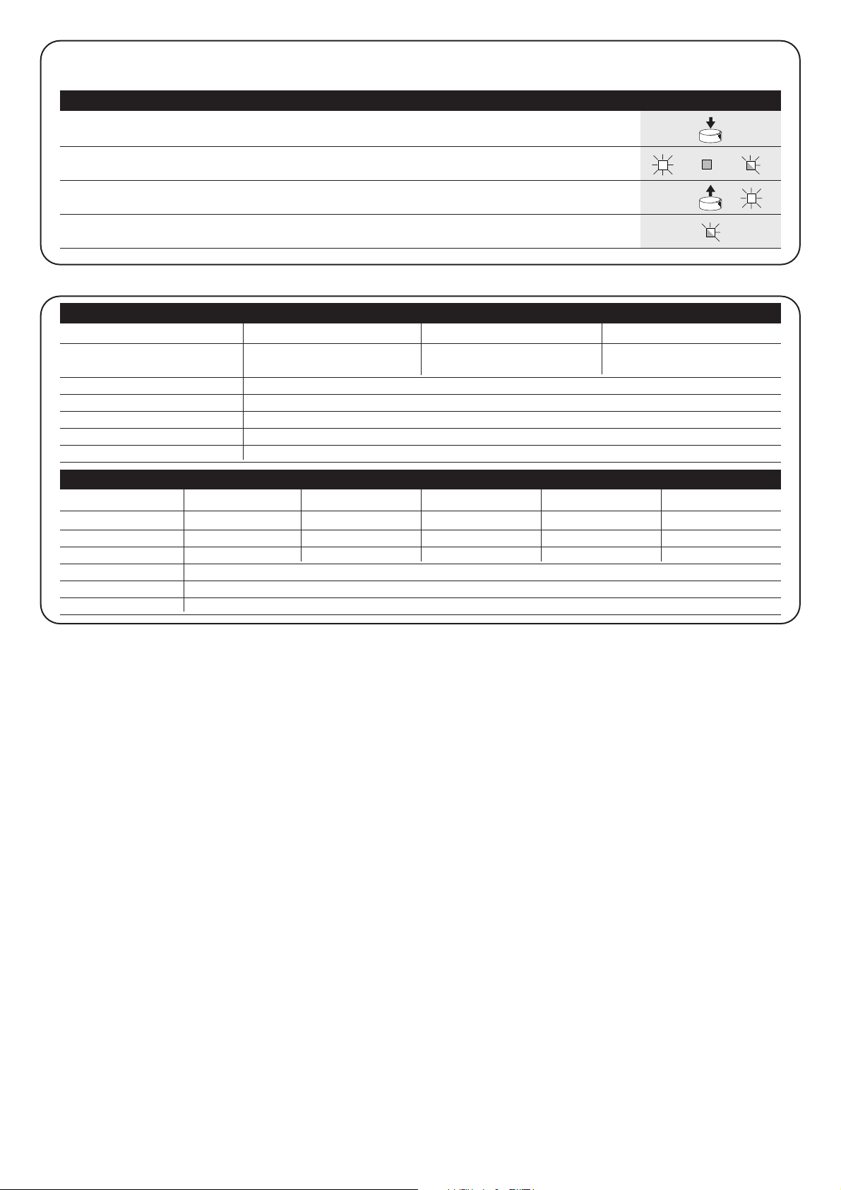
FLOR VERY VR FLO VERY VE SMILO
Tasti 1 – 2 - 4 2 1 – 2 - 4 2 2 - 4
Alimentazione 12Vdc Batt. 23A 6Vdc batt. litio 12Vdc Batt. 23° 6Vdc batt. litio 12Vdc Batt. 23A
Assorbimento 10mA 10mA 15mA 10mA 25mA
Frequenza 433.92MHz
Temp. di funzionamento -40°C ÷ + 85°C
Potenza irradiata 100µW
Cancellazione di tutti i trasmettitori
E’ possibile cancellare tutti i codici presenti in memoria con la seguente procedura:
x3
3°
x5
1. Premere e tenere premuto il pulsante sul ricevitore
2. Aspettare che il Led si accenda, poi aspettare che si spenga,
quindi aspettare che emetta 3 lampeggi
3. Rilasciare il tasto esattamente durante il 3° lampeggio
Nota: se la procedura è andata a buon fine, dopo qualche istante, il Led emetterà 5 lampeggi.
Ricevitori
Trasmettitori
Tabella “B4” Cancellazione di tutti i trasmettitori Esempio
RX
RX
SMXI SMXIS SMXIF
Decodifica Rolling code Rolling code 1024 combinazioni FLO
a 52 bit FLOR a 64 bit SMILO
Frequenza 433.92MHz
Impedenza di ingresso 52ohm
Uscite 4 (su connettore SMXI)
Sensibilità migliore di 0.5µV
Temperatura di funzionamento -20°C ÷ + 50°C
Caratteristiche tecniche
36
Page 37

37
I
Nice si riserva il diritto di apportare modifiche ai prodotti in qualsiasi momento riterrà necessario.
Dichiarazione CE di conformita’ / EC declaration of conformity
Numero /Number : 151/SMXI Data / Date: 09/2002 Revisione / Revision: 1
Il sottoscritto Lauro Buoro, Amministratore Delegato, dichiara che il prodotto:
The undersigned Lauro Buoro, General Manager of the following producer, declares that the product:
Nome produttore / Producer name:
NICE s.p.a.
Indirizzo / Address: Via Pezza Alta 13, 31046 Z.I. Rustignè –ODERZO- ITALY
Tipo / Type: Ricevitore radio 433MHz / Radio receiver 433MHz
Modello / Model: SMXI, SMXIS, SMXIF
Soddisfa tutti i requisiti essenziali applicabili alla direttiva R&TTE5/99, articolo 10.3.
Satisfies all the technical regulations applicable to R&TTE5/99 directive, article 10.3.
Risulta conforme a quanto previsto dalle seguenti Norme armonizzate / Complies with the following Harmonised standards
Riferimento n° Edizione Titolo norma
Livello di valutazione
Reference n° Issue Regulation title Assessment level
ETS300683 1997 Radio Equipment and Systems (RES);Electromagnetic Compatibility (EMC) standard for Classe II
Short Range Devices (SRD) operating on frequencies between 9KHz and 25GHz
EN300220-3 2000 APPARATI RADIO E SISTEMI Classe I (LPD)
CARATTERISTICHE TECNICHE E METODI DI MISURA PER APPARATI RADIO TRA
25MHz A 1000MHz/Radio Equipment and Sistems- Short Range Devices-Technical
characteristics and test methods for radio equipment between 25MHz and 1000 MHz
REGOLAZIONE ALL’USO DEI DISPOSITIVI A CORTO RAGGIO/Regolating to the use of
short range devices (SRD)
EN60950 2nd ed. 1992 APPARECCHIATURE PERLA TECNOLOGIA DELL’INFORMAZIONE. SICUREZZA.
+A1: 1993 + A2: 1993 + A3: 1995 + A4: 1997 + A11: 1997 + EN41003/1993.
Il prodotto suindicato si intende parte integrante di una delle configurazioni di installazione tipiche, come riportato nei nostri cataloghi generali
The above mentioned product is meant integral part of the of one of the installation configuration as shown on our general catalogues
ODERZO, 30 September 2002 (Amministratore Delegato)
(General Manager)
Lauro Buoro
Page 38

38
mindy A400
Recommandations:
Ce manuel est destiné exclusivement au personnel
technique qualifié pour l’installation.
Aucune information contenue dans ce fascicule ne peut être
considérée comme intéressante pour l’utilisateur final !
Ce manuel se réfère à l’armoire de commande A400 et ne
doit pas être utilisé pour d’autres produits.
L’armoire de commande A400 est destinée à l’actionnement des
opérateurs électromécaniques pour l’automatisation de portails ou
portes à battant, toute autre utilisation est impropre et donc interdite par
la réglementation en vigueur.
Nous conseillons de lire attentivement toutes les instructions, au moins
une fois, avant de procéder à l’installation.
!
Table des matières: pag.
1 Description du produit 39
2 Installation 39
2.1 Contrôles préliminaires 39
2.2 Fixation de l’armoire de commande A400 40
2.3 Installation typique 40
2.4 Connexions électriques 40
2.4.1 Schéma électrique 41
2.4.2 Description des connexions 41
2.4.3 Notes sur les connexions 42
2.4.4 Photo-test 42
2.4.5 Vérification des connexions 43
2.5
Recherche des butées de fin de course mécaniques
43
2.5.1 Recherche automatique 44
2.5.2
Recherche avec fonction ampèremétrique exclue
44
3 Fonctions programmables 45
3.1 Fonctions pré-programmées 45
pag.
4 Programmation 46
4.1 Effacement de la mémoire 46
4.2 Modalités de programmation 46
4.2.1 Programmation premier niveau: fonctions 47
4.2.2
Programmation deuxième niveau: paramètres
47
4.2.3 Exemple de programmation premier niveau 48
4.2.4
Exemple de programmation deuxième niveau
48
4.2.5 Schéma pour la programmation 49
5 Essai de fonctionnement 50
6 Accessoires en option 50
7
Maintenance de l’armoire de commande A400 50
7.1 Mise au rebut 50
8 Que faire si... 51
9 Caractéristiques techniques 51
Appendice:
Récepteur radio SMXI 52
Page 39

39
F
Le fonctionnement de l’armoire de commande A400 est basé sur un
système (ampèremétrique) qui vérifie l’effort des moteurs qui lui sont
connectés. Ce système permet de détecter automatiquement les
butées de fin de course et de reconnaître d’éventuels obstacles au
cours du mouvement normal (protection anti-écrasement).
Cette caractéristique rend l’installation très simple vu qu’aucun
réglage n’est nécessaire.
La logique de commande est pré-programmée sur les fonctions normalement requises, éventuellement, à travers une simple procédure
il est possible de choisir des fonctions plus spécifiques.
La fluctuation du courant dépend aussi d’autres facteurs en dehors de
l’effort, comme par exemple : variations de tension, le type de moteur, la
valeur du condensateur de démarrage, etc... La logique de commande A400
a été optimisée pour les moteurs présents dans les actionneurs Wingo,
d’autres types de moteurs pourraient provoquer un fonctionnement incorrect
de la logique de commande A400.
ABCDEFG H
I
L
M
N
OPQRS
T
A Connecteur primaire transformateur
B Relais Commun
C Relais Ouvre/Ferme
D Relais moteur M1
E Relais moteur M2
F Fusible très basse tension (500 mA)
G Connecteur secondaire transformateur
H Microprocesseur
I Connecteur pour récepteur radio
L Relais pour photo-test
M Led "ENTRÉES"
N Led "OK"
O Borne pour antenne radio
P Touches pour programmation
Q Bornes pour entrées-sorties
R Bornes pour moteurs et clignotant
S Bornes pour connexion secteur
T Fusible de secteur (5 A)
Pour protéger l’opérateur et la carte électronique
contre les dommages accidentels, les seules parties
accessibles de l’armoire de commande sont le bornier et
les touches de programmation. N’enlever le couvercle que
si cela est strictement nécessaire et après avoir coupé
l’alimentation électrique.
!
1) Description du produit
Nous rappelons que les automatismes de portes et de
portails doivent être installés exclusivement par du
personnel technique qualifié et dans le plein respect des
normes. Suivre attentivement les recommandations
données dans le chapitre "Recommandations pour
l’installateur".
!
2.1) Contrôles préliminaires
Avant toute opération, vérifier que tout le matériel est adapté à
l’installation et conforme à ce qui est prévu par les normes. En plus
de la vérification de tous les points indiqués dans les
"Recommandations pour l’installateur", nous indiquons dans cette
partie une liste des contrôles spécifiques pour l’armoire de
commande A400.
• Les “butées de fin de course mécaniques” doivent être capables
d’arrêter le mouvement du portail et doivent absorber sans
problèmes toute l’énergie cinétique accumulée dans le
mouvement du battant.
• Alimenter l’armoire de commande avec un câble de 3 x 1,5 mm
2
.
Si la distance entre l’armoire et la connexion à l’installation de mise
à la terre dépasse 30 m, il faut prévoir une prise de terre à
proximité de l’armoire.
• Pour les connexions de la partie à très basse tension de sécurité,
utiliser des câbles d’une section minimum de 0,25 mm
2
.
Utiliser des câbles blindés si la longueur dépasse 30 m en mettant
le blindage à la terre seulement du côté de l’armoire.
•Éviter d’effectuer des connexions de câbles dans des boîtiers
enterrés même s’ils sont complètement étanches.
• Si elle est correctement installée, l’armoire de commande garantit
un indice de protection IP 55 et peut donc être placée à l’extérieur.
• Fixer l’armoire sur une surface inamovible, plane et suffisamment
à l’abri de tout choc en veillant que le bas de l’armoire se trouve à
au moins 40 cm du sol.
• Introduire les éventuels passe-câbles ou tubes seulement par le
dessous du boîtier (voir figures 1, 1a).
2) Installation
Page 40

40
2.3) Installation typique
Pour préciser certains termes et certains aspects d’un automatisme
pour portes ou portails à 2 battants, nous donnons un exemple
typique.
En particulier, nous rappelons que:
• Toutes les photocellules produites par NICE disposent du système
de SYNCHRONISME qui permet d’éliminer le problème de
l’interférence entre deux paires de photocellules (pour plus de
détails se référer aux instructions des photocellules).
• La paire de photocellules "PHOTO" n’a pas d’effet en ouverture
tandis qu’elle provoque une inversion durant la fermeture.
• La paire de photocellules "PHOTO1" bloque la manœuvre aussi
bien en ouverture qu’en fermeture.
• La paire de photocellules "PHOTO2" (connectée sur l’entrée AUX
opportunément programmée) n’a pas d’effet en fermeture tandis
qu’elle provoque une inversion durant l’ouverture.
2.2) Fixation de l’armoire de commande A400
Le boîtier prévoit un couvercle qui protège la carte électronique
contre les contacts accidentels.
Seulement en cas de besoin, il est possible d’intervenir sur la carte
en agissant comme sur la figure 1a.
Pour faciliter le perçage du boîtier dans la partie inférieure, rabattre
le fond en plastique comme l’indique la réf. 1 figure 1a.
2.4) Connexions électriques
Pour garantir la sécurité de l’installateur et pour éviter
d’endommager les composants, quand on effectue les
connexions électriques ou qu’on branche le récepteur
radio, l’armoire de commande doit absolument être éteinte.
• Les entrées des contacts de type NF (Normalement Fermé), quand
elles ne sont pas utilisées, doivent être shuntées avec "commun
24V" (sauf les entrées des photocellules, pour plus de précisions
voir la fonction PHOTO-TEST).
• S’il y a plusieurs contacts NF pour la même entrée, il faut les
connecter en SÉRIE.
• Les entrées des contacts de type NO (Normalement Ouvert),
quand elles ne sont pas utilisées, doivent être laissées libres.
• S’il y a plusieurs contacts NO pour la même entrée, il faut les
connecter en PARALLÈLE.
• Les contacts doivent absolument être de type mécanique et libres
de toute puissance. Les connexions à étages type "PNP", "NPN",
"Open Collector", etc., ne sont pas admises.
• Dans les moteurs WINGO, le condensateur nécessaire au
fonctionnement est incorporé.
!
1 1a
FOTO 1
FOTO
FOTO 2
6
7
1
1
4
2
3
5
1.
Actionneurs électromécaniques
2.Clignotant
3.
Armoire de commande "A400"
4.Sélecteur à clé
5.
Paire de photocellules "PHOTO"
6.
Paire de photocellules "PHOTO1"
7.
Paire de photocellules "PHOTO2"
réf. 1
Page 41

41
F
2.4.1) Schéma électrique
1
LN
M1 M2
2
5 6 7 8 9 101112 1314 151617181920212223
24 25
34
P1
ALT
LED OK
P2
PP
ALIMENTATION
CLIGNOTANT
ANTENNE
OUVRE
COMMUN
FERME
OUVRE
COMMUN
FERME
COMMUN 24 V
24V
0
0
24V TX PHOTO
SCA 24 Vca
HALTE (NF)
PHOTO (NF)
PHOTO1 (NF)
PAS-À-PAS (NO)
AUX (NO)
PHOTO-TEST
24Vac
2.4.2) Description des connexions
Nous donnons ci-après une brève description des connexions possibles de l’armoire de commande vers l’extérieur.
Bornes Fonctions Description
1÷3 Alimentation Ligne d’alimentation de secteur
4 Terre Mise à la terre des moteurs
5÷6 Clignotant Connexion du clignotant à la tension de secteur (max. 40 W)
7÷9 Moteur 1 * Connexion du moteur M1 (battant inférieur)
10÷12 Moteur 2 * Connexion du moteur M2 (battant supérieur)
13÷14 Photo-test Alimentation TX photocellules (24 Vca max. 100 mA)
15÷16 24 Vca Alimentation service, RX photocellules, etc. (24 Vca max. 150 mA)
17 Commun 24 Vca Commun pour toutes les entrées/sorties
18 SCA Voyant portail ouvert (24 Vca max. 1,5 W)
19 Halt Entrée NF avec fonction de HALTE (urgence, blocage de sécurité)
20 Photo Entrée NF pour dispositifs de sécurité (photocellules, barres palpeuses)
21 Photo1 Entrée NF pour dispositifs de sécurité (photocellules, barres palpeuses)
22 Pas-à-Pas Entrée pour fonctionnement cyclique (OUVRE - STOP - FERME - STOP)
23 Aux ** Entrée auxiliaire
24÷25 Antenne Entrée pour l’antenne du récepteur radio
* Avec 2 moteurs, le premier qui entre en action dans la manœuvre d’ouverture est le moteur M2
La logique de commande A400 reconnaît automatiquement s’il y a un seul moteur installé qui devra être connecté à M2
** L’entrée auxiliaire AUX peut être programmée dans l’une de ces fonctions (voir chapitre 4 "Programmation"):
Fonction Type d’entrée Description
OUV. PARTIELLE type 1 NO Ouvre complètement le battant connecté au moteur M2
OUV. PARTIELLE type 1 NO Ouvre les 2 battants jusqu’à mi-course
OUVRE NO Effectue seulement la manœuvre d’ouverture
FERME NO Effectue seulement la manœuvre de fermeture
PHOTO 2 NF Fonction PHOTO 2
EXCLU -- Aucune fonction
À moins d’une programmation différente, l’entrée AUX effectue la fonction OUVERTURE PARTIELLE type 1
HALTE PP
ATTENTION: Connexion photocellules avec Phototest (voir chap. 2.4.4)
Note: armoire de commande préprogrammée et prévue pour le relevé automatique du temps de travail (voir chap. 2.5.1)
Page 42

42
La plupart des connexions sont extrêmement simples, pour une
bonne part il s’agit de connexions directes à un seul utilisateur ou
contact.
Les figures qui suivent donnent quelques exemples de connexion
des dispositifs extérieurs.
2.4.3) Notes sur les connexions
12345
12345
12345
12
12
12
LED OK
TX
PHOTO
PHOTO 1
PHOTO 2
RX
TX RX
TX RX
13
P1 P2 24 25
14 15 16 17 18 19 20 21 22 23
13
TX
PHOTO
1 123452
LED OK
P1 P2 24 25
RX
14 15 16 17 18 19 20 21 22 23
L’armoire de commande A400 dispose de série de la fonction de
PHOTO-TEST. Cette fonction constitue une excellente solution en
termes de fiabilité pour les dispositifs de sécurité et permet
d’atteindre, en ce qui concerne l’ensemble armoire + dispositifs de
sécurité, la "catégorie 2" selon la norme UNI EN 954-1 (éd.
12/1998).
À chaque fois qu’une manœuvre est commandée, tous les
dispositifs de sécurité sont contrôlés et la manœuvre commence
uniquement si le test est positif. Tout cela n’est possible que si l’on
emploie une configuration particulière pour les connexions des
dispositifs de sécurité, en pratique l’alimentation des émetteurs des
photocellules "TX" est séparée de celle des récepteurs "RX".
De plus, la fonction SYNCHRONISME (disponible dans toutes les
photocellules NICE) est l’unique méthode pour garantir que deux
paires de photocellules n’interfèrent pas entre elles).
Les entrées soumises à la procédure de photo-test sont PHOTO,
PHOTO1 et l’entrée AUX si elle est configurée comme PHOTO2. La phase de
photo-test a lieu au début de chaque manœuvre et ne peut pas être exclue ;
par conséquent, si l’une de ces entrées n’est pas utilisée, il faut la connecter
à la borne n°13 (voir les schémas ci-dessous pour les exemples de
connexion).
2.4.4) Photo-test
Le clignotement lent signale la
manœuvre d’ouverture
Le clignotement rapide signale la
manœuvre de fermeture
La lampe allumée fixe indique le
portail ouvert
S
chéma de connexion des photocellules PHOTO,
PHOTO1 et PHOTO2
Schéma de connexion seulement avec la photocellule PHOTO
Exemple 1
Comment connecter le sélecteur
pour effectuer les fonctions PASÀ-PAS et HALTE
E
xemple 2
C
omment connecter le sélecteur
pour effectuer les fonctions PASÀ-PAS et une de celles qui sont
prévues par l’entrée auxiliaire
(PIÉTONS, OUVRE SEULEMENT,
FERME SEULEMENT...)
Exemple de connexion d’une radio
extérieure alimentée à 24 Vca
1er Canal
➔
PAS-À-PAS
2e Canal
➔
AUX
C
onnexion Voyant P.O.
C
onnexion radio extérieure
Connexion sélecteur à clé
2 3
PAS-À-
PAS
HALTE
PAS-À-
PAS
AUX
NO
NF
NO
NO
24V
17
18
1,5W
1
15
16
22
17
23
12
24V
0V
2345612
PASSO
PASSO
COM
NA NC
17
22
19
17
PASSO
PASSO
COM COM
NA NA
17
22
23
17
ALT
COM
AUX
Page 43
43
F
Exemples unifilaires des connexions des photocellules
Connexion seulement de la photocellule PHOTO
(réf. Fig. 2)
Note: l’entrée PHOTO1 (21) n’est pas utilisée, elle doit donc être
connectée à la borne 13 pour permettre la fonction PHOTO-TEST
seulement à la photocellule PHOTO.
Connexion de PHOTO et PHOTO1
Note: respecter les connexions d’alimentation indiquées et activer la
fonction SYNCHRONISME (disponible dans toutes les photocellules NICE).
Connexion de PHOTO, PHOTO1 et PHOTO2
(réf. Fig. 3)
Note: respecter les connexions d’alimentation indiquées et activer la
fonction synchronisme (disponible dans toutes les photocellules
NICE).
12345
12
TX
PHOTO
RX
13
14
13
15
16
17
20
21
12345
12
12345
12
PHOTO
PHOTO
1
TX RX
TX RX
13
14
14
13
15
16
17
20
16
15
17
21
12345
12
12345
12
12345
12
PHOTO
TX RX
PHOTO 1
TX RX
PHOTO 2
TX RX
13
14
14
13
14
13
15
16
17
20
16
15
17
21
16
15
17
23
2.4.5) Vérification des connexions
Les prochaines opérations vous porteront à agir sur
des circuits sous tension, certaines parties sont soumises
à la tension de secteur et donc TRÈS DANGEREUSES !
Faites très attention à ce que vous faites et N’OPÉREZ
JAMAIS SEULS!
Une fois que les connexions prévues pour l’automatisme sont
terminées, on peut passer à la phase de vérification.
• Alimenter l’armoire de commande et vérifier que toutes les diodes
électroluminescentes (LED) clignotent rapidement pendant
quelques secondes.
• Vérifier que la tension de secteur est présente sur les bornes 1-2,
et qu’elle est d’environ 24 Vca sur les bornes 15-16 ; si les valeurs
sont différentes, couper immédiatement le courant et vérifier plus
attentivement les connexions et la tension d’alimentation.
• Après le clignotement rapide initial, la LED OK signale le
fonctionnement correct de l’armoire de commande par un
clignotement régulier toutes les secondes. Quand il y a une
variation sur les entrées, la LED OK effectue un double
clignotement rapide en signalant ainsi que l’entrée a été reconnue.
• Si les connexions sont correctes, les entrées de type NF, c’est-à-
dire HALTE, PHOTO, PHOTO1 doivent avoir la LED
correspondante allumée. Les LED de PAS-À-PAS et AUX doivent
résulter éteintes (si les entrées PHOTO2 et AUX sont présentes et
correctement programmées, la LED AUX doit être allumée)
• Vérifier que l’actionnement des dispositifs connectés aux entrées
provoque l’allumage ou l’extinction des LED correspondantes.
!
2.5) Recherche des butées de fin de course
mécaniques
Après avoir effectué les différents contrôles, on peut commencer la
phase de recherche automatique des butées de fin de course
mécaniques. Cette opération est nécessaire parce que la logique de
commande A400 doit "mesurer" la durée des manœuvres
d’ouverture et de fermeture.
Si l’armoire de commande n’a jamais été installée, ce qui signifie qu’il n’y
a encore aucun temps valable dans la mémoire de la logique de commande,
la procédure est activée automatiquement. Si par contre la procédure a déjà
été exécutée, pour pouvoir la réactiver, il faut d’abord effacer la mémoire (voir
chapitre "Programmation - Effacement de la mémoire"). Pour vérifier si la
mémoire contient des temps, éteindre puis rallumer l’alimentation de l’armoire
de commande : si toutes les LED clignotent rapidement pendant 10
secondes, la mémoire est vide ; si le clignotement ne dure que 3 secondes,
la mémoire contient déjà les temps de manœuvre des moteurs.
HALTE PHOTO AUXPHOTO1PAS-
À-PAS
HALTE PP
ALT Foto Foto1Passo
Passo
AUX
P1 P2
ALT PP
Page 44

44
2.5.2)
Recherche avec fonction ampèremétrique exclue
Quand le système de détection ampèremétrique ne réagit pas
comme il le faut, il est possible de faire fonctionner la logique de
commande seulement sur la base des temps en excluant
complètement la fonction ampèremétrique (voir la section
"Programmation paramètres et fonctions" pour exclure la fonction
ampèremétrique)
Dans ce cas, c’est l’installateur qui doit "avertir" la logique de
commande que la butée de fin de course mécanique a été atteinte.
• Avant de commencer la recherche avec fonction ampèremétrique
exclue, vérifier que tous les dispositifs de sécurité donnent leur
accord (HALTE, PHOTO et PHOTO1 actifs).
• Les battants peuvent se trouver dans n’importe quelle position
mais il est préférable qu’ils soient à mi-course.
• Presser la touche PP qui lance la phase de recherche
consistant en:
– Brève ouverture , d’abord M2 puis M1.
Si les moteurs ne commencent pas la manœuvre d’ouverture ou
si le premier à exécuter la manœuvre n’est pas M2, bloquer la
recherche en pressant la touche HALTE et contrôler les
connexions des moteurs.
– Fermeture du moteur M1 jusqu’à la butée de fin de course
mécanique en fermeture
• Presser PP quand M1 a atteint la butée de fin course
mécanique en fermeture.
– Fermeture du moteur M2 jusqu’à la butée de fin de course
mécanique en fermeture
• Presser PP quand M2 a atteint la butée de fin course
mécanique en fermeture.
– Au bout de quelques instants, commencement de la manœuvre
d’ouverture du moteur M2
• Presser PP quand M2 a atteint la butée de fin course
mécanique en ouverture.
– Au bout de quelques instants, commencement de la manœuvre
d’ouverture du moteur M1.
• Presser PP quand M1 a atteint la butée de fin course
mécanique en ouverture.
– Au bout de quelques instants, commencement d’une manœuvre
complète de fermeture.
Les moteurs peuvent commencer la manœuvre à des moments
différents, l’objectif est d’arriver en fermeture en maintenant un
décalage suffisant pour éviter le risque de cisaillement entre les
battants.
– Fin de la procédure avec mémorisation de tous les temps
mesurés.
Toutes ces phases doivent se dérouler l’une après l’autre,
l’installateur doit intervenir en pressant PP seulement aux moments
indiqués. Si la procédure ne s’effectue pas correctement, il faut
l’interrompre en pressant la touche HALTE. L’activation d’un
dispositif de sécurité ou l’arrivée d’une commande durant la
procédure en provoque l’interruption immédiate.
2.5.1) Recherche automatique
Cette procédure est complètement automatique et se base sur la
mesure de l’effort des moteurs pour la détection des butées de fin
de course mécaniques en ouverture et en fermeture.
Dans des conditions d’automatisation particulièrement critiques, il peut se
produire que le système de détection de la variation de courant des moteurs
ne réagisse pas comme il le faut ; essayer dans ce cas de modifier le niveau
d’intervention de la fonction ampèremétrique ou utiliser éventuellement un
fonctionnement exclusivement basé sur le temps (voir le paragraphe
"recherche avec la fonction ampèremétrique exclue").
• Avant de commencer la recherche automatique, vérifier que tous
les dispositifs de sécurité donnent leur accord (HALTE, PHOTO et
PHOTO1 actifs). L’activation d’un dispositif de sécurité ou l’arrivée
d’une commande durant la procédure en provoque l’interruption
immédiate.
• Les battants peuvent se trouver dans n’importe quelle position
mais il est préférable qu’ils soient à mi-course.
• Presser la touche PP qui lance la phase de recherche
consistant en:
– Brève ouverture, d’abord M2 puis M1.
Si les moteurs ne commencent pas la manœuvre d’ouverture ou
si le premier à exécuter la manœuvre n’est pas M2, bloquer la
recherche en pressant la touche HALTE et contrôler les
connexions des moteurs.
– Fermeture du moteur M1 jusqu’à la butée de fin de course
mécanique en fermeture
– Fermeture du moteur M2 jusqu’à la butée de fin de course
mécanique en fermeture
– Commencement de la manœuvre d’ouverture du moteur M2
– Après le décalage prévu, commencement de la manœuvre
d’ouverture du moteur M1.
Si le décalage n’est pas suffisant, bloquer la recherche en
pressant la touche HALTE puis modifier le temps (voir chapitre
"Programmation")
– Mesure du temps nécessaire pour que les moteurs atteignent les
butées de fin de course mécaniques en ouverture
– Manœuvre complète de fermeture
Les moteurs peuvent commencer la manœuvre à des moments
différents, l’objectif est d’arriver en fermeture en maintenant un
décalage suffisant pour éviter le risque de cisaillement entre les
battants.
– Fin de la procédure avec mémorisation de tous les temps
mesurés.
Toutes ces phases doivent se dérouler l’une après l’autre sans
aucune intervention de la part de l’installateur. Si ce n’est pas le cas,
la procédure ne s’effectue pas correctement et il faut l’interrompre
en pressant la touche HALTE. Vérifier les connexions puis répéter la
procédure en modifiant éventuellement aussi les seuils d’intervention
de la fonction ampèremétrique (voir le chapitre "Programmation").
ALT PP
P1 P2
HALTE PP
ALT PP
P1 P2
HALTE PP
Page 45
45
F
L’armoire de commande A400 permet de programmer quelques fonctions
et paramètres pour rendre l’installation plus adaptée aux exigences de
l’utilisateur et plus sûre dans les différentes conditions d’utilisation.
Fonctionnement "automatique"
Ce mode de fonctionnement prévoit une fermeture automatique
après le temps de pause programmé, initialement le temps de pause
est programmé à 20 secondes mais peut être modifié à 5, 10, 20,
40, 80 secondes.
Fonctionnement "collectif"
Ce mode de fonctionnement est utile quand de nombreuses
personnes utilisent l’automatisme avec une commande radio. Si
cette fonction est active, chaque commande reçue provoque une
manœuvre d’ouverture qui ne peut pas être interrompue par d’autres
impulsions de commande à l’exception des commandes
d’urgence/sécurité (HALTE, PHOTO1, PHOTO2) et refermeture
immédiate (AUX configuré comme "Ferme seulement").
Préclignotement
La fonction permet d’activer le clignotant avant le début de la manœuvre
pendant le temps programmable de 2,4,6,8, ou 10 secondes.
Referme 4 secondes après le passage devant la
photocellule PHOTO
Avec la fermeture automatique, la fonction permet de réduire le
temps de pause à 4 secondes après que la photocellule PHOTO ait
été libérée, c’est-à-dire que le portail se ferme 4 secondes après le
passage de l’utilisateur.
Décalage battants
Cette fonction provoque en ouverture un retard dans l’activation du
moteur M1 par rapport à M2, nécessaire pour éviter que les battants
puissent se coincer. Le décalage en fermeture est toujours présent
(exigé par les normes de sécurité) et il est calculé automatiquement
par la logique de commande de manière à obtenir le même décalage
que celui qui est programmé en ouverture.
Sensibilité ampèremétrique
L’armoire de commande dispose d’un système pour la mesure du
courant absorbé par les deux moteurs, utilisé pour détecter les
butées de fin de course mécaniques et les éventuels obstacles
durant le mouvement du portail. Vu que le courant absorbé dépend
de conditions variables (poids du portail, frottements divers, coups
de vent, variations de tension, etc.) il a été prévu de pouvoir modifier
le seuil d’intervention.
Le réglage prévoit cinq degrés : le degré n°1 est le plus sensible, le
degré n°5 est le moins sensible. Initialement le réglage prévoit le
degré n°2 qui devrait être le plus indiqué pour la plupart des
installations.
Entrée auxiliaire AUX
L’armoire de commande prévoit une entrée auxiliaire qui peut être
configurée avec l’une des fonctions suivantes :
• Ouverture partielle type 1: exécute la même fonction que
l’entrée PAS-À-PAS en provoquant l’ouverture seulement du
moteur M2. Fonctionne seulement avec le portail complètement
fermé, autrement la commande est interprétée comme s’il y avait
une commande PAS-À-PAS.
• Ouverture partielle type 2: exécute la même fonction que
l’entrée PAS-À-PAS en provoquant l’ouverture des deux battants
seulement pendant la moitié du temps prévu pour l’ouverture
totale. Fonctionne seulement avec le portail complètement fermé,
autrement la commande est interprétée comme s’il y avait une
commande PAS-À-PAS.
• Ouvre seulement: cette entrée effectue seulement l’ouverture
avec la séquence Ouvre-Stop-Ouvre-Stop.
• Ferme seulement: cette entrée effectue seulement l’ouverture
avec la séquence Ferme-Stop-Ferme-Stop.
• Photo 2: exécute la fonction du dispositif de sécurité "PHOTO 2"
• Exclue: l’entrée n’a aucune fonction.
Le principe de fonctionnement du système
ampèremétrique se base sur les variations de courant
absorbées par les moteurs, si au début de la manœuvre le
moteur est bloqué parce que le battant est déjà sur la butée
de fin de course mécanique, il n’y aura aucune variation de
courant et donc l’obstacle ne sera pas détecté.
La fonction "ampèremétrique" correctement réglée (ainsi
que d’autres précautions indispensables) peut être utile pour
le respect des dernières normes européennes EN 12453 et
EN 12445, qui demandent l’emploi de techniques ou de
dispositifs pour limiter les forces et le risque lié aux
mouvements des portes et portails automatiques.
Si les conditions le rendent nécessaire, il est possible d’exclure la fonction
ampèremétrique et de faire fonctionner l’armoire de commande
exclusivement en fonction du temps (voir le paragraphe "recherche avec
fonction ampèremétrique exclue").
Si la fonction ampèremétrique est exclue, les moteurs
continuent à "pleine force" pendant toute la durée de la
manœuvre.
Effectuer une analyse attentive des risques et prévoir
d’autres éléments de sécurité dans l’installation pour
obtenir les niveaux de sécurité prévus par les normes.
!!!
3) Fonctions programmables
3.1) Fonctions pré-programmées
L’armoire de commande A400 dispose de quelques fonctions
programmables (voir chapitre "Fonctions programmables") ; après la
phase de recherche, ces fonctions sont pré-programmées suivant
une configuration typique qui satisfait la plupart des automatismes :
• Fermeture automatique : au bout de 20 secondes
• Décalage des battants : 4 secondes
• Préclignotement : désactivé
• Entrée auxiliaire : ouverture partielle type 1
(active seulement le moteur M2)
• Sensibilité ampèremétrique : degré 2
Les fonctions peuvent être modifiées à tout moment aussi bien
avant qu’après la phase de recherche à travers une procédure de
programmation.
Page 46
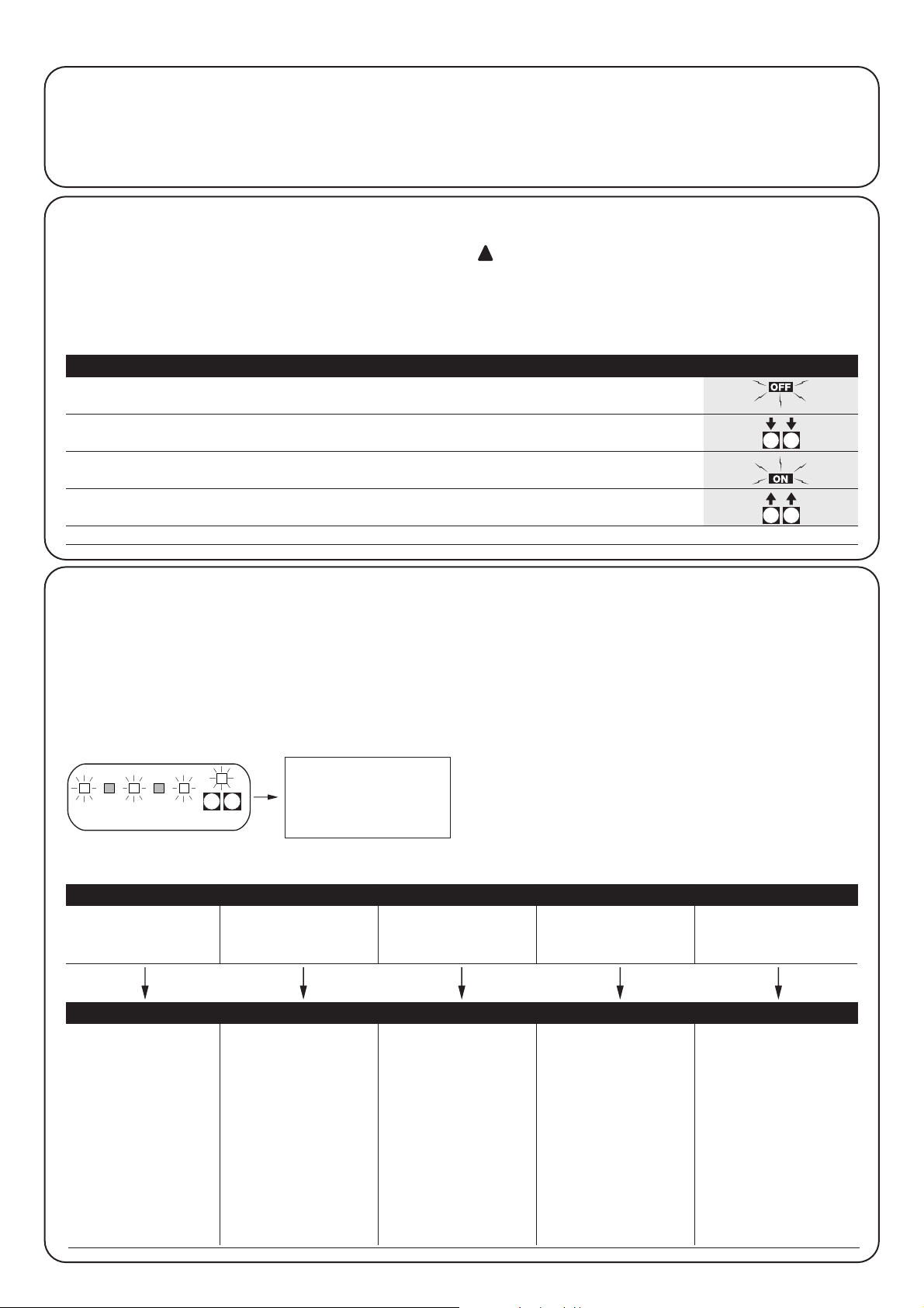
46
4.2) Modalités de programmation
Pour toutes les phases de programmation, on n’utilise que les deux
touches P1 et P2 présentes sur la carte.
De plus, les 5 LED "ENTRÉES" qui indiquent normalement l’état des
entrées, signalent, dans ce cas, le "paramètre" sélectionné.
Exemple:
Il existe 2 niveaux de programmation:
• Dans le premier niveau, il est possible d’activer ou de désactiver
les fonctions. Chaque LED ENTRÉES correspond à une fonction,
si la LED est allumée, la fonction est active, si elle est éteinte, elle
est désactivée.
Led 1 : Fonctionnement "Automatique"
Led 2 : Fonctionnement "Collectif"
Led 3 : Préclignotement
Led 4 : Referme après passage devant PHOTO
Led 5 : Décalage en ouverture
• Depuis le premier niveau, il est possible de passer au second
niveau où on peut choisir le paramètre relatif à la fonction, à
chaque LED correspond une valeur différente à associer au
paramètre.
4.1) Effacement de la mémoire
Chaque nouvelle programmation remplace les programmations
précédentes, il n’est donc normalement pas nécessaire de "tout
effacer".
Dans tous les cas, l’effacement total de la mémoire est possible avec
cette simple opération:
Après l’effacement de la mémoire, il faut procéder à
une nouvelle recherche des butées de fin de course
mécaniques, tandis que toutes les fonctions retournent
aux valeurs pré-programmées.
!
Premier niveau:
Led 1 Led 2 Led 3 Led 4 Led 5
Fonctionnement Fonctionnement Préclignotement Referme 4 s aprèsDécalage en ouverture
“Automatique”“Collectif” passage devant PHOTO
Deuxième niveau:
Paramètre: Paramètre: Paramètre: Paramètre: Paramètre:
Temps de pause Entrée AUX Temps de Sensibilité Temps de décalage
préclignotement ampèremétrique
Led 1 : 5s Led 1 : Ouv. part. type 1 Led 1 : 2s Led 1 : Degré 1 Led 1 : 2s
Led 2 : 10s Led 2 : Ouv. part. type 2 Led 2 : 4s Led 2 : Degré 2 Led 2 : 4s
Led 3 : 20s Led 3 : Ouvre seulement Led 3 : 6s Led 3 : Degré 3 Led 3 : 6s
Led 4 : 40s Led 4 : Ferme seulement Led 4 : 8s Led 4 : Degré 4 Led 4 : 8s
Led 5 : 80s Led 5 : PHOTO 2 Led 5 : 10s Led 5 : Degré 5 Led 5 : 10s
Led éteintes: Led éteintes: fonction
entrée exclue ampèremétrique exclue
Degré 1 = plus sensible
Degré 5 = moins sensible
Toutes les fonctions décrites dans le chapitre "Fonctions
programmables" peuvent être choisies à travers une phase de
programmation qui se termine avec la mémorisation des choix
effectués.
L’armoire de commande contient donc une mémoire qui conserve
les fonctions et les paramètres propres à l’automatisme.
4) Programmation
3s
Tableau "A1" Pour effacer la mémoire: Exemple
1. Éteindre l’alimentation de l’armoire de commande
2. Presser et maintenir enfoncées les touches P1 et P2 sur la carte
3. Rétablir l’alimentation de l’armoire de commande
4. Attendre au moins 3 secondes puis relâcher les deux touches
N.B.: si l’effacement de la mémoire a été fait correctement toutes les LED s’éteignent pendant 1 seconde
12345
P1 P2
P2P1
P2P1
Dans ce cas, sont actifs: la
fonction "Automatique",
le préclignotement et le
décalage en ouverture du
moteur M1.
Page 47

47
F
3s ...ou... 60s,
...ou...
P1
3s
3s
1. Entrer en programmation premier niveau
(en pressant P1 et P2 pendant au moins 3 secondes)
2. Sélectionner la fonction en pressant P1 de manière à porter la LED clignotante
sur le point désiré
3. Entrer dans le deuxième niveau en maintenant la touche P2 enfoncée
pendant au moins 3 secondes
3s ... ou ... 60s,
... ou ...
1. Presser P1 pendant au moins 3 secondes, ou attendre 1 minute,
ou éteindre l’alimentation
4.2.1) Programmation premier niveau : fonctions
Nans le premier niveau Il est possible d’activer ou de désactiver les
fonctions.
Dans le premier niveau, la LED OK est toujours allumée, les LED
ENTRÉES allumées indiquent que les fonctions sont actives, les LED
éteintes indiquent qu’elles sont désactivées.
La LED clignotante indique la fonction sélectionnée, si le
clignotement est bref la fonction est désactivée, si le clignotement
est long, la fonction est active.
3s
Tableau “B1” Pour entrer dans la programmation premier niveau: Exemple
1. Maintenir les touches P1 et P2 enfoncées pendant au moins 3 secondes
Un clignotement rapide de toutes les LED indique qu’on est entré en programmation
3s
1. Presser plusieurs fois P1 de manière à porter la LED clignotante sur la fonction désirée
2. Presser P2 pour activer ou désactiver la fonction. Si le clignotement est bref, la fonction
est désactivée, si le clignotement est long la fonction est active
Tableau “B3” Pour sortir du premier niveau en confirmant les modifications: Exemple
1. Maintenir les touches P1 et P2 enfoncées pendant au moins 3 secondes
Tableau “B4” Pour sortir du premier niveau en annulant les modifications: Exemple
1. Presser P1 pendant au moins 3 secondes, ou attendre 1 minute
ou éteindre l’alimentation
P2P1
P2P1
P1
P2
Tableau “B2” Pour activer ou désactiver une fonction: Exemple
Tableau “C5” Pour sortir du premier niveau en annulant les modifications: Exemple
(y compris celles du deuxième niveau)
P2P1
4.2.2) Programmation deuxième niveau : paramètres
Dans le deuxième niveau, il est possible de choisir le paramètre relatif
à la fonction. Le deuxième niveau peut être atteint seulement en
passant par le premier niveau.
Dans le deuxième niveau, la LED OK clignote rapidement tandis
que les LED ENTRÉES indiquent le paramètre sélectionné.
Tableau “C1” Pour entrer dans la programmation deuxième niveau: Exemple
Tableau “C2” Pour choisir le paramètre: Exemple
1. Presser plusieurs fois P2 de manière à porter la LED sur le paramètre désiré
Tableau “C3” Pour revenir au premier niveau: Exemple
1. Presser P1
3s
Tableau “C4” Pour sortir du premier niveau en confirmant les modifications: Exemple
(y compris celles du deuxième niveau)
1. Maintenir les touches P1 et P2 enfoncées pendant au moins 3 secondes
P2P1
P1
P2
P1
P2
P1
Page 48

48
3s
x3
x1
3s
Exemple de programmation premier niveau: Exemple
activer la fonction "Referme après passage devant PHOTO" et désactiver le "Décalage en ouverture"
1. Entrer en programmation premier niveau en pressant P1 et P2 pendant
au moins 3 secondes
2. Presser 3 fois P1 de manière à porter la LED clignotante sur la LED ENTRÉES N°4
(le clignotement est bref)
3. Activer la fonction "Referme après passage devant PHOTO" en pressant P2
(le clignotement deviendra long)
4. Presser une fois P1 pour porter la LED clignotante sur la LED ENTRÉES N°5
(le clignotement est long)
5. Désactiver la fonction "Décalage en ouverture" en pressant P2
(le clignotement deviendra bref)
6. Sortir de la programmation, avec mémorisation en pressant P1 et P2
pendant au moins 3 secondes
4.2.3) Exemple de programmation premier niveau
Dans ces exemples, nous décrivons les étapes nécessaires pour
activer et désactiver une fonction au premier niveau, comme par
exemple pour activer la fonction "Referme après passage devant
PHOTO" et désactiver "Décalage en ouverture" des battants.
3s
x3
3s
x4
3s
Exemple de programmation deuxième niveau: Exemple
modifier la "sensibilité de la fonction ampèremétrique"
1. Entrer en programmation premier niveau en pressant P1 et P2
pendant au moins 3 secondes
2. Presser 3 fois P1 de manière à porter la LED clignotante sur la LED ENTRÉES N°4
3. Passer au deuxième niveau en pressant P2 pendant au moins 3 secondes
4. Presser 4 fois P2 jusqu’à ce que toutes les LED ENTRÉES soient éteintes
(fonction ampèremétrique exclue)
5. Revenir au premier niveau en pressant P1
6. Sortir de la programmation, avec mémorisation en pressant P1 et P2
pendant au moins 3 secondes
4.2.4) Exemple de programmation deuxième
niveau
Dans ces exemples, nous décrivons les étapes nécessaires pour
modifier un paramètre au deuxième niveau, comme par exemple
pour modifier la sensibilité de la fonction ampèremétrique jusqu’à
"fonction ampèremétrique exclue".
P2P1
P2P1
P1
4
P1
5
P2
P2P2P2
P2P1
P2P1
P1
4
P1
Page 49

49
F
P1 P2
P1 P2
P1 P2
P1 P2
P1 P2
P1 P2
on
off
4.2.5) Schéma pour la programmation
La figure ci-dessous illustre le schéma complet de la programmation
des fonctions et des paramètres correspondants.
Elle indique également les fonctions et les paramètres pré-
programmés initialement ou après un effacement complet de la
mémoire.
(*)
o. p. type 1 ouverture partielle type 1
seul le moteur 2 entre en action (NO)
o. p. type 2 ouverture partielle type 2
les deux moteurs entrent en action pendant la moitié
du temps de travail (NO)
ouvre seulement ouvre
➔ stop➔ ouvre➔ stop... (NO)
ferme seulement ferme
➔ stop➔ ferme➔ stop... (NO)
photo 2 utilisé comme photo 2 (NF)
Page 50

50
L’essai de fonctionnement de l’automatisme doit être
effectué par du personnel qualifié et expérimenté qui
devra se charger d’établir les essais prévus en fonction du
risque présent.
L’essai de fonctionnement est la partie la plus importante de toute la
phase de réalisation de l’automatisme. Chaque composant, comme
les moteurs, le récepteur radio, l’arrêt d’urgence, les photocellules et
autres dispositifs de sécurité, peut nécessiter une phase d’essai
spécifique; nous conseillons de suivre les procédures indiquées
dans les manuels d’instructions correspondants.
Pour l’essai de l’armoire de commande A400, exécuter la procédure qui
suit (la séquence se réfère à l’armoire de commande A400 avec les
fonctions pré-programmées).
• Vérifier que l’activation de l’entrée PAS-À-PAS provoque la séquence
de mouvements : Ouvre, Stop, Ferme, Stop.
• Vérifier que l’activation de l’entrée AUX (fonction ouverture partielle
type 1) gère la séquence : Ouvre, Stop, Ferme, Stop seulement du
moteur 2 tandis que le moteur 1 reste arrêté en fermeture.
• Solliciter une après l’autre les photocellules ou les autres dispositifs
de sécurité connectés aux entrées PHOTO, PHOTO1 et PHOTO2 et
vérifier que l’activation d’une entrée de commande ne provoque
aucune manœuvre.
• Faire commencer une manœuvre d’ouverture et vérifier que:
– quand on sollicite PHOTO, le portail continue la manœuvre
d’ouverture.
– quand on sollicite PHOTO1 la manœuvre s’arrête jusqu’à ce que
PHOTO1 soit libérée puis la manœuvre reprend le mouvement
d’ouverture
– si PHOTO2 est installée, après avoir sollicité ce dispositif, la
manœuvre doit s’arrêter puis repartir en fermeture.
• Vérifier que quand le battant arrive à la butée de fin de course
mécanique en ouverture, le moteur s’éteint.
• Faire commencer une manœuvre de fermeture et vérifier que:
– quand on sollicite PHOTO, le portail s’arrête et repart en ouverture.
– quand on sollicite PHOTO1 la manœuvre s’arrête jusqu’à ce que
PHOTO1 soit libérée puis la manœuvre reprend le mouvement
d’ouverture
– quand on sollicite PHOTO2 le portail continue la manœuvre de
fermeture.
• Vérifier que les dispositifs d’arrêt connectés à l’entrée de HALTE
provoquent l’arrêt immédiat de n’importe quel mouvement en cours.
• Vérifier que le niveau du système de détection des obstacles est
adapté à l’application.
–
Durant la manœuvre, aussi bien en ouverture qu’en fermeture, empêcher
le mouvement du battant en simulant un obstacle et vérifier que la
manœuvre s’invertit avant de dépasser la force prévue par les normes.
• D’autres vérifications pourront être nécessaires en fonction des
dispositifs connectés aux entrées.
Si pendant deux manœuvres consécutives dans la même direction un
obstacle est détecté, la logique de commande effectue une inversion partielle
des deux moteurs pendant 1 seconde seulement.
À la commande successive, les battants commencent une manœuvre
d’ouverture et la première intervention de la fonction ampèremétrique pour
chaque moteur est considérée comme un arrêt en ouverture.
On a la même séquence quand le courant de secteur est rétabli après une
coupure : la première commande est toujours d’ouverture et le premier
obstacle est toujours considéré comme un arrêt en ouverture.
!
5) Essai de fonctionnement
L’armoire de commande A400, comme composant électronique, n’a
besoin d’aucune maintenance particulière. Vérifier toutefois
périodiquement, au moins deux fois par an, le bon fonctionnement
de toute l’installation en effectuant les contrôles indiqués dans le
chapitre Essai de fonctionnement.
7) Maintenance de l’armoire de commande A400
7.1) Mise au rebut
Ce produit est constitué de différents types de matériaux dont
certains peuvent être recyclés.
Informez-vous sur les méthodes de recyclage ou de mise au rebut
en suivant les normes en vigueur sur le plan local.
Certains composants électroniques peuvent contenir
des substances polluantes, ne les abandonnez pas dans la
nature.
!
6) Accessoires en option
Carte RADIO
L’armoire comprend un connecteur pour brancher une carte radio embrochable SM, qui permet d’agir sur l’entrée de “Pas-à-Pas” et “Aux2”
et commander de cette manière l’armoire à distance avec un émetteur.
sortie 1 P.P.
sortie 2 AUX2
sortie 3 non utilisée
sortie 4 non utilisée
Page 51

51
F
9) Caractéristiques techniques
Alimentation : Armoire de commande A400 ➔ 230 Vca ±10%, 50÷60 Hz
: Armoire de commande A400/V1 ➔ 120 Vca ±10%, 50÷60 Hz
Courant maximum moteurs : Armoire de commande A400 ➔ 1,2 A (avec rotor bloqué)
: Armoire de commande A400/V1 ➔ 2,5 A (avec rotor bloqué)
Sortie alimentation services : 24 Vca, courant maximum 150mA
Sortie photo-test : 24 Vca, courant maximum 100mA
Sortie clignotant : pour clignotant à la tension de secteur, puissance max. 40 W
Sortie voyant portail ouvert : pour lampe voyant à 24 Vca puissance maximum 1,5 W
Durée maximum manœuvre : 60 secondes
Temps de pause : programmable à 5, 10, 20, 40, 80 secondes
Temps de décalage battant en ouverture : programmable à 2, 4, 6, 8, 10 secondes
Temps de préclignotement : programmable à 2, 4, 6, 8, 10 secondes
Température de fonctionnement : -20°C ÷ 50°C
Indice de protection boîtier : IP 55
Dimensions et poids : 230 x 180 h 100 mm, environ 1100 g
Ce chapitre est un guide visant à aider l’installateur à résoudre
quelques uns des problèmes les plus courants qui peuvent se
présenter durant l’installation.
Aucune LED ne résulte allumée
• Vérifier si l’armoire de commande est alimentée (mesurer si la
tension de secteur arrive aux bornes 1-2 et s’il y a une tension de
24 Vca aux bornes 15-16)
• Vérifier les deux fusibles, si la LED OK n’est pas allumée elle non
plus ou si elle clignote, on est probablement en présence d’une
panne grave et l’armoire devra être remplacée.
La LED OK clignote régulièrement mais les LED ENTRÉES
ne reflètent pas l’état des entrées respectives
•Éteindre momentanément l’alimentation pour sortir d’une
éventuelle phase de programmation.
• Vérifier attentivement les connexions sur les bornes de 13 à 23.
La procédure de "Recherche automatique" ne démarre pas
• La procédure de "Recherche automatique" s’active seulement si
elle n’a jamais été effectuée ou si la mémoire a été effacée. Pour
vérifier si la mémoire est vide, éteindre momentanément
l’alimentation, à l’allumage toutes les LED doivent clignoter
rapidement pendant 10 secondes. Si elles clignotent seulement
pendant 3 secondes, la mémoire contient déjà des valeurs
valables. Si l’on désire effectuer une nouvelle "Recherche
automatique", il faut effacer complètement la mémoire.
La "Recherche automatique" n’a jamais été effectuée
mais la procédure ne démarre pas ou se déroule de
manière incorrecte
• Pour activer la procédure de "Recherche automatique" il faut que
l’installation et tous les dispositifs de sécurité fonctionnent
correctement, en particulier les photocellules qui sont soumises à
la phase de "Photo-test".
• S’assurer qu’aucun dispositif connecté aux entrées n’intervient
durant la "Recherche automatique".
• Pour que la "Recherche automatique" démarre correctement, les
LED sur les entrées doivent être allumés suivant la figure, la LED
OK doit clignoter au rythme d’un clignotement à la seconde.
La "Recherche automatique" a été effectuée correctement
mais la manœuvre ne démarre pas
• Vérifier que les LED des sécurités (HALTE, PHOTO, PHOTO1 et
éventuellement PHOTO2) sont allumées et que les LED de la
commande qui est activée (PAS-À-PAS ou AUX) s’allume pendant
la durée de la commande.
Durant le mouvement, le portail effectue une inversion
Les causes qui provoquent une inversion sont les suivantes:
• Une intervention des photocellules (PHOTO2 en ouverture,
PHOTO ou PHOTO1 durant la fermeture) ; dans ce cas, contrôler
les connexions des photocellules et vérifier éventuellement les
LED de signalisation des entrées.
• Une intervention du dispositif ampèremétrique durant la course
des moteurs (et donc pas à proximité des butées de fin de course
mécaniques) est considérée comme un obstacle et provoque une
inversion. Pour contrôler si le dispositif ampèremétrique est
intervenu, vérifier la LED OK : un clignotement rapide (par rapport
au rythme normal d’1 à la seconde) indique que l’intervention du
dispositif ampèremétrique est liée au moteur M1, deux
clignotements rapides indiquent que l’intervention est liée au
moteur M2.
8) Que faire si...:
HALTE PHOTO AUXPHOTO1PAS-
À-PAS
HALTE PP
ALT Foto Foto1Passo
Passo
AUX
P1 P2
ALT PP
Page 52

smxi récepteur radio
Description du produit
La particularité de ce récepteur radio est que le code d’identification est différent
pour chaque émetteur (et de plus, il change à chaque fois qu’il est utilisé). Par
conséquent pour permettre au récepteur de reconnaître un émetteur donné, il
faut procéder à la mémorisation du code d’identification. Cette opération doit être
répétée pour tous les émetteurs que l’on désire associer à l’armoire de
commande.
Il est possible de mémoriser dans le récepteur jusqu’à un maximum de 256
émetteurs. Il n’est pas prévu de pouvoir effacer un seul émetteur mais seulement tous
les codes en même temps.
- Pour des fonctions plus avancées, utiliser l’unité de programmation prévue à cet effet.
Dans la phase de mémorisation du code de l’émetteur, il est
possible de choisir entre ces deux options:
Mode I. Chaque touche de l’émetteur active la sortie correspon-
dante dans le récepteur, c’est-à-dire que la touche 1 active la sortie
1, la touche 2 active la sortie 2 et ainsi de suite. Dans ce cas, il y a
une unique phase de mémorisation pour chaque émetteur, durant
cette phase la pression d’une touche ou d’une autre n’a pas
d’importance et une seule place en mémoire est occupée.
Mode II. À chaque touche de l’émetteur, il est possible d’associer
une sortie particulière du récepteur, par exemple la touche 1 active la
sortie 2, la touche 2 active la sortie 1, etc. Dans ce cas, il faut
mémoriser l’émetteur en pressant la touche désirée pour chaque
sortie à activer. Naturellement, chaque touche ne peut activer qu’une
seule sortie tandis que la même sortie peut être activée par plusieurs
touches. Une seule place en mémoire est occupée par chaque
touche.
Installation antenne
Pour obtenir un bon fonctionnement, le récepteur a besoin d’une
antenne type ABF ou ABFKIT ; sans antenne, la portée est réduite à
quelques mètres. L’antenne doit être installée le plus haut possible ;
en présence de structures métalliques ou de béton armé, installer
l’antenne au-dessus de ces dernières. Si le câble fourni avec
l’antenne est trop court, utiliser un câble coaxial avec une impédance
de 50 ohms (par ex. RG58 à perte faible). La longueur du câble ne
doit pas être supérieure à 10 m.
Si l’antenne est installée dans un endroit ne disposant pas d’un bon
plan de terre (structures en maçonnerie) il est possible de connecter
la borne du conducteur externe à la terre en obtenant ainsi une
meilleure portée. Naturellement, la prise de terre doit se trouver à
proximité et être de bonne qualité. S’il n’est pas possible d’installer
l’antenne accordée ABF ou ABFKIT, on peut obtenir des résultats
corrects en utilisant comme antenne un bout de fil fourni avec le
récepteur, monté à plat.
52
Page 53

Mémorisation d’un émetteur
Quand on active la phase de mémorisation, n’importe
quel émetteur correctement reconnu dans le rayon de
réception de la radio est mémorisé. Évaluer attentivement
cet aspect, débrancher éventuellement l’antenne pour
réduire la capacité du récepteur.
Les procédures pour la mémorisation des émetteurs ont un temps
limite pour leur exécution ; il faut donc lire et comprendre toute la
procédure avant de commencer les opérations.
Pour effectuer la procédure qui suit, il faut utiliser la touche présente
sur le boîtier du récepteur radio (référence A, Fig. 1b), et la Led
correspondante (référence B, Fig. 1b) à gauche de la touche.
3s
2s
x3
2s
x3
1.
Presser la touche sur le récepteur et la maintenir enfoncée pendant au moins
3 secondes
2. Quand la LED s’allume, relâcher la touche
3. Dans les 10 secondes qui suivent, presser pendant au moins 2 secondes
la 1°touche de l’émetteur à mémoriser
N.B.: Si la mémorisation a été effectuée correctement, la LED sur le récepteur clignotera 3 fois.
S’il y a d’autres émetteurs à mémoriser, répéter le point 3 dans les 10 secondes qui suivent.
La phase de mémorisation prend fin si aucun nouveau code n’est reçu dans les 10 secondes.
Tableau “B1” Mémorisation mode I Exemple
(chaque touche active la sortie correspondante dans le récepteur)
1.
Presser la touche sur le récepteur et la relâcher un nombre de fois correspondant
à la sortie désirée (2 clignotements pour la sortie n°2)
2. Vérifier que la LED émet un nombre de clignotements correspondant à la
sortie désirée (2 clignotements pour la sortie n°2)
3. Dans les 10 secondes qui suivent, presser pendant au moins 2 secondes
la touche désirée de l’émetteur à mémoriser
N.B.: Si la mémorisation a été effectuée correctement, la LED sur le récepteur clignotera 3 fois.
S’il y a d’autres émetteurs à mémoriser, répéter le point 3 dans les 10 secondes qui suivent.
La phase de mémorisation prend fin si aucun nouveau code n’est reçu dans les 10 secondes.
Tableau “B2” Mémorisation mode II Exemple
(il est possible d’associer à chaque touche une sortie particulière)
RX
RXTXTX
RX
1b
x5s
1s 1s 1s
x1
1. Presser la touche sur le NOUVEL émetteur pendant au moins 5 secondes, puis la relâcher
2. Presser lentement 3 fois de suite la touche sur l’ANCIEN émetteur
3. Presser lentement 1 fois la touche sur le NOUVEL émetteur puis la relâcher
N.B.: S’il y a d’autres émetteurs à mémoriser, répéter ces trois p oints pour chaque nouvel émetteur
Tableau “B3” Mémorisation à distance Exemple
TX
TXTXTX
TX
TX
Mémorisation à distance
Il est possible de mémoriser un nouvel émetteur dans la mémoire du
récepteur sans agir directement sur la touche. Il faut disposer pour
cela d’un émetteur déjà mémorisé et fonctionnant correctement. Le
nouvel émetteur "héritera" des caractéristiques de celui qui est déjà
mémorisé. Par conséquent, si le premier émetteur est mémorisé en
mode I, le nouveau sera mémorisé lui aussi en mode I et on pourra
presser n’importe quelle touche des émetteurs. Si le premier
émetteur est mémorisé en mode II, le nouveau sera mémorisé lui
aussi en mode II mais il faudra presser sur le premier émetteur la
touche qui active la sortie désirée et sur le deuxième émetteur la
touche que l’on veut mémoriser. Il est nécessaire de lire toutes les
instructions puis d’effectuer les opérations l’une après l’autre sans
interruptions. Maintenant, avec les deux émetteurs que nous
appellerons NOUVEAU celui avec le code à introduire et ANCIEN
celui qui est déjà mémorisé, se placer dans le rayon d’action des
radiocommandes (sans aller au-delà de la portée maximum) et
effectuer les opérations indiquées dans le tableau.
53
F
Page 54

FLOR VERY VR FLO VERY VE SMILO
Touches 1 – 2 - 4 2 1 – 2 - 4 2 2 - 4
Alimentation 12Vdc pile 23A 6Vdc pile lithium 12Vdc pile 23° 6Vdc pile lithium 12Vdc pile 23A
Absorption 10mA 10mA 15mA 10mA 25mA
Fréquence 433.92 MHz
Temp. de fonctionnement
-40°C ÷ + 85°C
Puissance irrad. 100 µW
Effacement de tous les émetteurs
Il est possible d’effacer tous les codes présents dans la mémoire avec la procédure suivante :
x3
3°
x5
1. Presser la touche sur le récepteur et la maintenir enfoncée
2. Attendre que la LED s’allume puis attendre qu’elle s’éteigne,
attendre enfin qu’elle clignote trois fois
3. Relâcher la touche exactement durant le troisième clignotement
N.B. : Si la mémorisation a été effectuée correctement, après peu la LED clignotera 5 fois
Récepteurs
Émetteurs
Tableau “B4” Effacement de tous les émetteurs Exemple
RX
RX
SMXI SMXIS SMXIF
Décodage Rolling code Rolling code 1024 combinaisons FLO
à 52 bits FLOR à 64 bits SMILO
Fréquence 433.92 MHz
Impédance d’entrée 52 ohms
Sorties 4 (sur connecteur SMXI)
Sensibilité supérieure à 0.5 µV
Temp. de fonctionnement -20°C ÷ + 50°C
Caractéristiques techniques du système
54
Page 55

55
F
Nice se réserve le droit d’apporter des modifications aux produits à tout moment si elle le juge nécessaire.
Dichiarazione CE di conformita’ / EC declaration of conformity
Numero /Number : 151/SMXI Data / Date: 09/2002 Revisione / Revision: 1
Il sottoscritto Lauro Buoro, Amministratore Delegato, dichiara che il prodotto:
The undersigned Lauro Buoro, General Manager of the following producer, declares that the product:
Nome produttore / Producer name:
NICE s.p.a.
Indirizzo / Address: Via Pezza Alta 13, 31046 Z.I. Rustignè –ODERZO- ITALY
Tipo / Type: Ricevitore radio 433MHz / Radio receiver 433MHz
Modello / Model: SMXI, SMXIS, SMXIF
Soddisfa tutti i requisiti essenziali applicabili alla direttiva R&TTE5/99, articolo 10.3.
Satisfies all the technical regulations applicable to R&TTE5/99 directive, article 10.3.
Risulta conforme a quanto previsto dalle seguenti Norme armonizzate / Complies with the following Harmonised standards
Riferimento n° Edizione Titolo norma
Livello di valutazione
Reference n° Issue Regulation title Assessment level
ETS300683 1997 Radio Equipment and Systems (RES);Electromagnetic Compatibility (EMC) standard for Classe II
Short Range Devices (SRD) operating on frequencies between 9KHz and 25GHz
EN300220-3 2000 APPARATI RADIO E SISTEMI Classe I (LPD)
CARATTERISTICHE TECNICHE E METODI DI MISURA PER APPARATI RADIO TRA
25MHz A 1000MHz/Radio Equipment and Sistems- Short Range Devices-Technical
characteristics and test methods for radio equipment between 25MHz and 1000 MHz
REGOLAZIONE ALL’USO DEI DISPOSITIVI A CORTO RAGGIO/Regolating to the use of
short range devices (SRD)
EN60950 2nd ed. 1992 APPARECCHIATURE PERLA TECNOLOGIA DELL’INFORMAZIONE. SICUREZZA.
+A1: 1993 + A2: 1993 + A3: 1995 + A4: 1997 + A11: 1997 + EN41003/1993.
Il prodotto suindicato si intende parte integrante di una delle configurazioni di installazione tipiche, come riportato nei nostri cataloghi generali
The above mentioned product is meant integral part of the of one of the installation configuration as shown on our general catalogues
ODERZO, 30 September 2002 (Amministratore Delegato)
(General Manager)
Lauro Buoro
Page 56

56
Anmerkungen:
Vorliegendes Handbuch ist ausschließlich für technisches
Fachpersonal bestimmt, das zur Installation der
Steuerzentrale berechtigt ist. Keine Information dieses
Handbuches ist für den Endverbraucher bestimmt!
Dieses Handbuch ist ausschließlich für die A400Steuerzentrale bestimmt und darf für kein anderes Produkt
verwendet werden.
Der Zweck dieser Zentrale ist die Steuerung elektromechanischer
Arbeitszylinder für die Automatisierung von Toren oder Schwingtüren;
jede andere Art von Verwendung ist unzulässig und nach den geltenden
Normen verboten.
Wir empfehlen Ihnen, vor der Installation alle Anweisungen mindestens
einmal durchzulesen.
!
mindy A400
Inhaltsverzeichnis: pag.
1 Beschreibung des Produktes 57
2 Installation 57
2.1 Kontrollen vor Inbetriebnahme 57
2.2 Befestigung der Steuerzentrale A400 58
2.3 Typische Anlage 58
2.4 Elektrische Anschlüsse 58
2.4.1 Schaltplan 59
2.4.2 Beschreibung der Verbindungen 59
2.4.3 Anmerkungen zu den Verbindungen 60
2.4.4 Photozellen-Test 60
2.4.5 Kontrolle der Verbindungen 61
2.5 Suche der Endanschläge 61
2.5.1 Automatische Suche 62
2.5.2 Suche mit Ausschluss des Strommessers 62
3 Programmierbare Funktionen 63
3.1 Vorprogrammierte Funktionen 63
pag.
4 Programmierung 64
4.1 Löschen des Speichers 64
4.2 Programmierverfahren 64
4.2.1
Programmierung des ersten Niveaus: Funktionen
65
4.2.2
Programmierung des zweiten Niveaus: Parameter
65
4.2.3
Beispiel für die Programmierung im ersten Niveau
66
4.2.4
Beispiel für die Programmierung im zweiten Niveau
66
4.2.5 Programmierschema 67
5 Abnahme 68
6 Sonderzubehör68
7 Wartung der A400-Steuerzentrale 68
7.1 Entsorgung 68
8 Was machen, wenn... 69
9 Technische Merkmale 69
Anhang:
SMXI-Funkempfänger 70
Page 57

57
D
Die Steuerzentrale A400 funktioniert über ein Strommesssystem,
das die Kraft der mit der Steuerzentrale verbundenen Motoren
überprüft. Dieses System misst die Endanschläge automatisch und
erkennt eventuelle Hindernisse während des normalen
Bewegungsablaufs (Quetschschutz).
Dieses Merkmal erleichtert die Installierung sehr, da nichts eingestellt
werden muss.
Die Steuerzentrale ist für die normalerweise gewünschten
Standardfunktionen vorprogrammiert. Besondere Funktionen kön-
nen bei Bedarf durch ein einfaches Verfahren gewählt werden.
Der Verlauf des Stroms hängt nicht nur von der Motorkraft, sondern auch
von anderen Faktoren ab wie Spannungsänderungen, Motortyp,
Startkondensatorwert usw. Die Steuerzentrale A400 wurde für die in den
Wingo-Arbeitszylindern vorhandenen Motoren abgestimmt, andere
Motorentypen könnten einen unsachgemäßen Betrieb der Steuerzentrale
A400 hervorrufen.
ABCDEFG H
I
L
M
N
OPQRS
T
A Primärverbinder des Transformators
B Gemeinsames Relais
C Relais Öffnen/Schließen
D Motor M1-Relais
E Motor M2-Relais
F Schmelzsicherung Niederspannung (500mA)
G Sekundärverbinder des Transformators
H Mikroprozessor
I Einsteckvorrichtung für Funkempfänger
L Photozellen-Test-Relais
M Leuchtanzeige “EINGÄNGE”
N Leuchtanzeige “OK”
O Klemme für Funkantenne
P Druckknöpfe zum Programmieren
Q Klemmen für Eingänge-Ausgänge
R Klemmen für Motor und Blinklicht
S Haubtversorgungsklemmen
T Schmelzsicherung für die Leitung (5A)
Zum Schutz des Bedieners und der Speicherkarte vor
ungewollten Eingriffen an der Steuerzentrale sind
normalerweise nur die Klemmbretter und die
Programmiertasten zugänglich.
Nehmen Sie den Deckel nur dann ab, wenn es wirklich
nötig ist und nachdem Sie die Stromzufuhr ausgeschaltet
haben.
!
1) Beschreibung des Produktes:
Wir möchten daran erinnern, dass die Anlagen der
Tore und automatischen Türen nur von technischem
Fachpersonal, unter Beachtung der Gesetzesnormen
installiert werden dürfen.
Die Anmerkungen dieses Handbuches “Hinweise für den
Installateur” müssen aufmerksam befolgt werden.
!
2.1) Kontrollen vor Inbetriebnahme
Überprüfen Sie vor Arbeitsbeginn, dass das gesamte Material zur
Installation geeignet ist und den geltenden Normen entspricht. In
diesem Handbuch finden Sie alle Kontrollen für die in den
“Anweisungen für den Installateur” enthaltenen Hinweise sowie eine
Liste für spezielle Kontrollen der Steuerzentrale A400.
•
Die “mechanischen Feststellvorrichtungen der Bewegung” müssen
zum Anhalten des Tores geeignet sein und problemlos die während
der Bewegung des Tores entwickelte kinetische Energie auffangen.
• Verwenden Sie für die Stromversorgung der Steuerzentrale ein
3x1,5 mm
2
großes Kabel. Sollte die Entfernung zwischen der
Zentrale und dem Anschluss der Erdanlage mehr als 30 m betragen, müssen Sie in der Nähe der Steuerzentrale einen
Erdanschluss anbringen.
• Benutzen Sie für Verbindungen mit dem Teil mit dem
Niederspannungsteil kleine Kabel mit einem Mindestquerschnitt
von 0,25 mm
2
.
Benutzen Sie abgeschirmte Kabel, wenn die Leitungen länger als
30 m sind und erden Sie die Abschirmung nur von der Seite der
Steuerzentrale aus.
• Vermeiden Sie Verbindungen an Kabeln in Gehäusen, die unter
der Erde verlegt wurden, selbst wenn diese vollkommen
wasserundurchlässig sind.
• Wenn die Steuerzentrale sachgemäß installiert wurde, wird ein
hoher Schutzgrad (IP55) garantiert, so dass die Steuerzentrale
auch im Freien installiert werden kann.
• Befestigen Sie die Steuerzentrale auf einer unbeweglichen, ebenen und sachgemäß gegen Stöße geschützten Oberfläche und
beachten Sie, dass sich der untere Teil mindestens 40 cm vom
Boden befindet.
• Fügen Sie geeignete Kabel- oder Rohrdurchgänge nur im unteren
Teil des Gehäuses ein (s. Abb.1, Abb.1a).
2) Installation:
Page 58

58
2.3) Typische Anlage
Um einige Begriffe und einige Aspekte einer Automatisierungsanlage
für Türen und Tore besser zu erklären, nennen wir Ihnen im
folgenden ein typisches Beispiel für die Anlage von Türen und
Flügeltoren mit Anschlag.
Zudem möchten wir Ihnen folgendes in Erinnerung rufen:
• Alle von Nice hergestellten Photozellen verfügen über ein
SYNCHRON-System, dank dem keine Störungen zwischen zwei
Photozellen-Paaren entstehen (weitere Erklärungen finden Sie in
den Anleitungen der Photozellen).
• Das Photozellen-Paar “FOTO” tritt beim Öffnen nicht in Kraft,
während es beim Schließvorgang für das Umkehren der
Bewegung sorgt.
• Das Photozellen-Paar “FOTO1” blockiert den Bewegungsvorgang
beim Öffnen und beim Schließen.
• Das Photozellen-Paar “FOTO2” (wird auf dem dafür
programmierten AUX-Eingang angeschlossen) tritt beim Schließen
nicht in Kraft, sondern sorgt für das Umkehren der Bewegung
beim Öffnen.
2.2) Befestigung der Steuerzentrale A400
Zu dem Gehäuse gehört ein Deckel, der die Speicherkarte vor
ungewollten Berührungen schützt.
Eingriffe auf der Speicherkarte sollten nur bei Bedarf vorgenommen
werden; wenn solche Eingriffe nötig werden, gehen Sie wie in Abb.
1a gezeigt vor.
Um das Bohren des Gehäuses im unteren Teil zu erleichtern,
nehmen Sie den Plastikboden wie in Abb. 1a gezeigt ab.
2.4) Elektrische Anschlüsse
Um die Sicherheit des Installateurs zu gewährleisten
und um Schäden an den Bauteilen während der
Durchführung der elektrischen Anschlüsse oder beim
Einschalten des Funkempfängers zu vermeiden, muss die
Steuerzentrale auf jeden Fall ausgeschaltet werden.
• Die Eingänge der NC-Kontakte (normalerweise geschlossene K.)
müssen bei Nichtbenutzung mit dem gemeinsamen 24 V Leiter
überbrückt werden (ausgenommen die Eingänge der Photozellen;
zum besseren Verständnis s. Funktion PHOTOZELLEN-TEST).
• Sollten an einem Eingang mehrere NC-Kontakte vorhanden sein,
müssen diese untereinander REIHENGESCHALTET werden.
• Die Eingänge der NA-Kontakte (normalerweise geöffnete K.)
müssen bei Nichtbenutzung freigelassen werden.
• Sollten an einem Eingang mehrere NA-Kontakte vorhanden sein,
müssen diese untereinander PARALLEL GESCHALTET werden.
• Die Kontakte müssen auf jeden Fall mechanisch und ohne
jegliches Potential sein, Stufenschaltungen wie die sog. “PNP”,
“NPN” und “Open Collector”-Anschlüsse usw. sind unzulässig.
• Der für den Betrieb der WINGO-Motoren nötige Kondensator ist
bereits eingebaut.
!
1 1a
FOTO 1
FOTO
FOTO 2
6
7
1
1
4
2
3
5
1.
Elektromechanische Arbeitszylinder
2.Blinkleuchte
3.Steuerzentrale “A400”
4.Wählschalter
5.Photozellen-Paar “FOTO”
6.Photozellen-Paar “FOTO1”
7.Photozellen-Paar “FOTO2”
Teil 1
Page 59
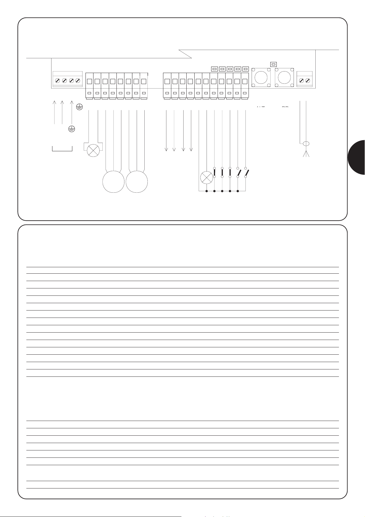
59
D
2.4.1) Schaltplan
1
LN
M1 M2
2
5 6 7 8 9 101112 1314 151617181920212223
24 25
34
P1
ALT
LED OK
P2
PP
STROMZUFUHR
BLINKLEUCHTE
ANTENNE
ÖFFNET
GEMEINSAM
SCHLIEßT
ÖFFNET
GEMEINSAM
SCHLIEßT
gemeinsam 24 V
24V
0
0
24V TX PHOTO
SCA 24 Vca
HALT
FOTO
FOTO 1
SCHRITTZYKLUS
AUX
PHOTOZELLENTEST
24Vac
2.4.2) Beschreibung der Verbindungen
In folgender Tabelle finden Sie eine Beschreibung aller möglicher Anschlüsse der Steuerzentrale mit externen Geräten.
Klemmen Funktionen Beschreibung
1÷3 Stromversorgung Stromleitung vom Netz
4 Erdung Erdanschluss der Motoren
5÷6 Blinkleuchte Verbindung der Blinkleuchte bei Netzspannung (max.40W)
7÷9 Motor 1 * Verbindung des M1-Motors (unterer Flügel)
10÷12 Motor 2 * Verbindung des M2-Motors (oberer Flügel)
13÷14 Photozellentest Stromversorgung TX Fotozellen (24V max. 100mA)
15÷16 24 V-Wechselstrom Stromversorgung Betrieb, RX-Fotozellen, usw. (24V-Wechselstrom max 150 mA)
17 Gemeinsam 24 V Gemeinsam für alle Eingänge/Ausgänge Wechselstrom
18 SCA Leuchtanzeige offenes Tor (14V-Wechselstrom, max. Wechselstrom 1,5 W Wechselstrom)
19 Halt Normalerw.geschlossener Eingang mit HALT-Funktion (Notstopp, Sicherheitsblockierung)
20 Foto
Normalerw. geschlossener Eingang für Sicherheitsvorrichtungen (Photozellen, pneumatische Sicherheitsleisten)
21 Foto 1
Normalerw. geschlossener Eingang für Sicherheitsvorrichtungen (Photozellen, pneumatische Sicherheitsleisten)
22 Schritt-Schritt Eingang für zyklischen Betrieb (ÖFFNET-STOPP-SCHLIESST-STOPP)
23 AUX **Hilfseingang
24 Antenne Eingang für Antenne des Funkempfängers
* mit 2 Motoren, der erste beim Öffnen sich bewegende Motor ist Motor M2.
Die Zentrale A400 erkennt automatisch, ob nur 1 Motor installiert wurde, der mit Motor M2 verbunden werden muss.
** Eine dieser Funktionen kann am Hilfseingang AUX programmiert werden (s. Kapitel 4 “Programmierung):
Funktion Art des Eingangs Beschreibung
ÖFFNET Typ 1 TEILWEISE NA Öffnet den mit Motor 2 verbundenen Flügel vollkommen
ÖFFNET Typ 2 TEILWEISE NA Öffnet die beiden Flügel bis zur Mitte des Torlaufs
ÖFFNET NA Führt nur das Öffnungsmanöver aus
SCHLIESST NA Führt nur das Schließmanöver aus
FOTO 2 NC Funktion FOTO 2
AUSGESCHLOSSEN -- Keine Funktion
NA = normalerweise geöffnet
NC = normalerweise geschlossen
Wenn der Eingang AUX nicht anders programmiert wurde, führt er die Funktion ÖFFNET TEILWEISE Typ 1 aus.
HALT PP
LEUCHTANZEIGE OK
ACHTUNG: Photozellenanschluss mit Photozellentest (siehe 2.4.4)
Hinweis: vorprogrammierte Steuerung, für die automatische Vermessung der Arbeitszeit vorbereitet (siehe 2.5.1)
Page 60
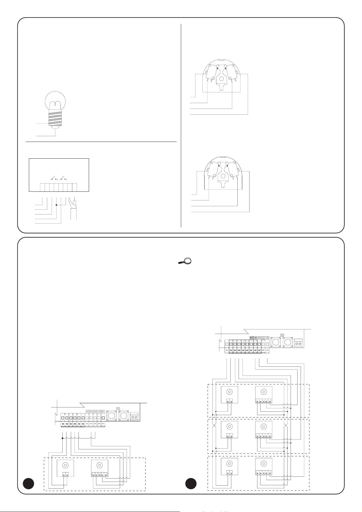
60
Der Großteil der Verbindungen ist sehr leicht auszuführen, meist
handelt es sich um direkte Anschlüsse an einen einzelnen
Stromverbraucher oder Kontakt. In den folgenden Abbildungen
finden Sie einige Beispiele, wie man die Vorrichtungen außen
anschließen kann.
2.4.3) Anmerkungen zu den Verbindungen
12345
12345
12345
12
12
12
LED OK
TX
FOTO
FOTO1
FOTO 2
RX
TX RX
TX RX
13
P1 P2 24 25
14 15 16 17 18 19 20 21 22 23
13
TX
FOTO
1 123452
LED OK
P1 P2 24 25
RX
14 15 16 17 18 19 20 21 22 23
Die Steuerzentrale A400 verfügt über eine serienmäßige
PHOTOZELLEN-TEST-Funktion. Eine in Bezug auf die
Sicherheitsvorrichtungen ausgezeichnete und zuverlässige Lösung,
dank der die gesamte Steuerzentrale und die Sicherheit die
“Kategorie 2” der UNI EN 954-1-Norm (Ausgabe 12/1998) erreichen.
Bei jeder neuen Bewegung werden alle Sicherheitsvorrichtungen
überprüft und erst, wenn der Test positiv ausfällt, wird das
Kommando ausgeführt. All dies ist erst möglich, wenn die
Sicherheitsvorrichtungen in einer besonderen Konfiguration
zueinander stehen, konkret bedeutet dies, dass die “TX”-Sender der
Photozellen in Bezug auf die “RX”-Empfänger separat mit Strom
versorgt werden.
Zudem ist die “SYNCHRON”-Funktion (in allen NICE-Photozellen
enthalten) die einzige Methode, um zu garantieren, dass die beiden
Photozellen-Paare sich nicht gegenseitig stören.
Die Eingänge mit dem Photozellen-Test-Vorgang sind FOTO, FOTO1 und
der AUX-Eingang, wenn dieser als FOTO2 angeordnet ist. Die PhotozellenTestphase schaltet sich bei Beginn eines jeden Bewegungsmanövers ein und
kann nicht abgeschaltet werden. Wenn einer dieser Eingänge nicht benutzt
wird, muss er mit der Klemme Nr. 13 verbunden werden, s. folgende
Abbildungen mit Anschlussbeispielen.
2.4.4) Photozellen-Test
Langsames Blinken zeigt die
Öffnungsphase an.
Schnelles Blinken zeigt die
Schließphase an.
Ständig brennende Leuchtanzeige
zeigt an, dass das Tor offen ist.
Verbindungsschema der Photozellen FOTO, FOTO1 und
FOTO 2.
Verbindungsschema mit nur einer FOTO-Photozelle
Beispiel 1
Wie man den Wählschalter
anschließt, um die Funktionen
SCHRITTZYKLUS und HALT
auszuführen.
Beispiel 2
Wie man den Wählschalter
anschließt, um die Funktionen
SCHRITTZYKLUS und eine der
vom Hilfseingang vorgesehenen
Funktionen auszuführen.
(FUSSGÄNGER, ÖFFNET NUR,
SCHLIESST NUR).
Beispiel für den Anschluss eines
Außenfunks mit 24 V WechselstromStromzufuhr.
1. Kana
➔
SCHRITTZYKLUS
2. Kana
➔
AUX
Anschluss der Leuchtanzeige Wechselstrom
Anschluss des Funks außen
Anschluss des Wählschalters
2 3
SCHRITT-
ZYKLUS
HALT
SCHRITT-
ZYKLUS
AUX
24V
17
18
1,5W
1
15
16
22
17
23
12
24V
0V
2345612
PASSO
PASSO
COM
NA NC
17
22
19
17
PASSO
PASSO
COM COM
NA NA
17
22
23
17
ALT
COM
AUX
Page 61
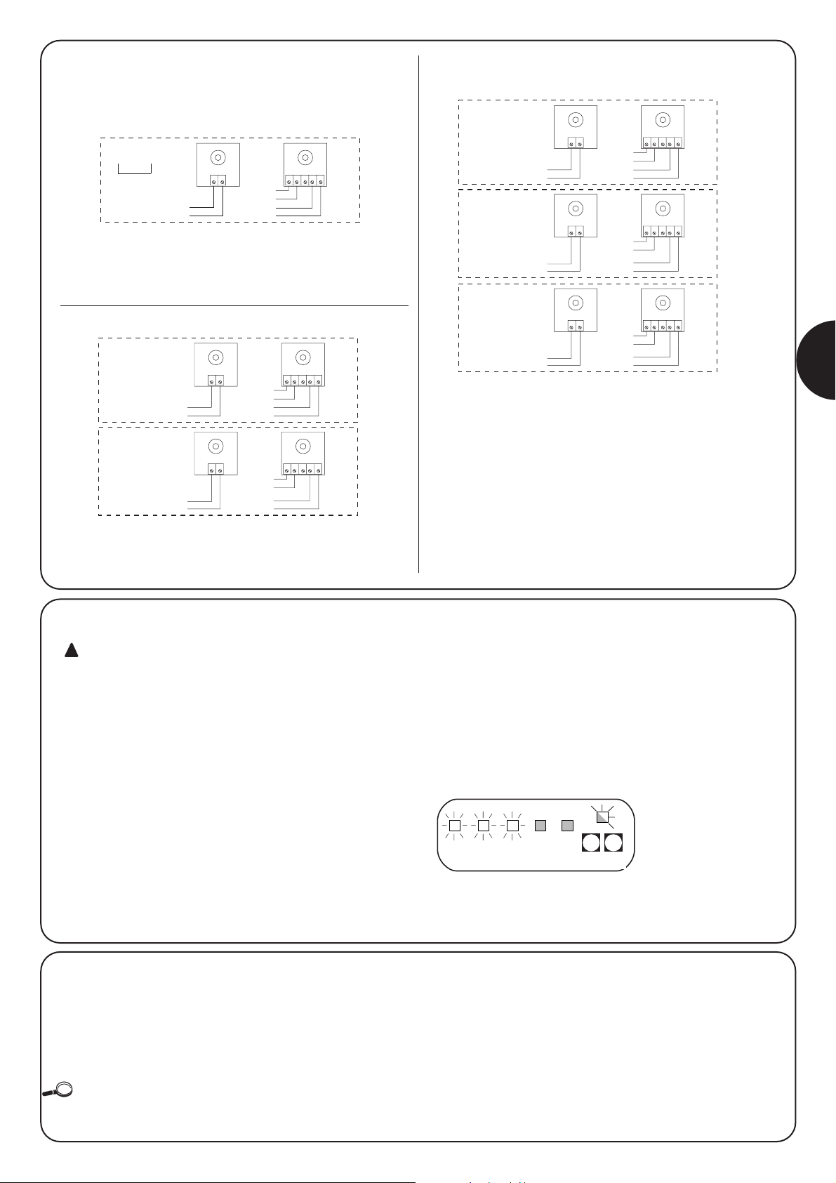
61
D
Eindrähtige Beispiele für die Verbindungen der Photozellen
Verbindung einer einzigen Photozelle FOTO
(Ref. Abb.2)
Anmerkung: Der FOTO1 (21) Eingang wird nicht benutzt, deshalb
muss er an die Klemme 13 angeschlossen werden, damit FOTO
allein die Funktion PHOTOZELLEN-TEST ausführen kann.
Verbindung von FOTO und FOTO1
Anmerkung: Beachten Sie die beschriebenen Verbindungen der
Stromzuführung und aktivieren Sie die Funktion SYNCHRONISMUS
(bei allen NICE-Photozellen vorhanden).
Verbindung von FOTO, FOTO1 und FOTO2
(Ref.: Abb.3)
Anmerkung: Beachten Sie die beschriebenen Verbindungen der
Stromzuführung und aktivieren Sie die Funktion SYNCHRONISMUS
(bei allen NICE-Photozellen vorhanden).
12345
12
TX
FOTO
RX
13
14
13
15
16
17
20
21
12345
12
12345
12
FOTO
FOTO 1
TX RX
TX RX
13
14
14
13
15
16
17
20
16
15
17
21
12345
12
12345
12
12345
12
FOTO
TX RX
FOTO 1
TX RX
FOTO 2
TX RX
13
14
14
13
14
13
15
16
17
20
16
15
17
21
16
15
17
23
2.4.5) Kontrolle der Verbindungen
Folgende Schritte werden unter Spannung ausgeführt;
einige Teile stehen direkt unter Netzspannung und sind
ÄUSSERST GEFÄHRLICH! Lassen Sie bei allen
Arbeitsschritten äußerste Vorsicht walten und
UNTERNEHMEN SIE NICHTS ALLEIN!
Nach Beendigung der für die Automatik vorgesehenen
Verbindungen kann die Kontrolle durchgeführt werden.
• Versorgen Sie die Steuerzentrale mit Strom und überprüfen Sie,
dass alle Leuchtanzeigen einige Sekunden lang schnell
aufleuchten.
•Überprüfen Sie, dass auf den Klemmen 1-2 Netzspannung und
auf den Klemmen 15-16 eine 24 V Wechselstrom-Spannung liegt.
Sollten die Werte nicht dem Richtwert entsprechen, schalten Sie
sofort den Strom ab und überprüfen Sie die Verbindungen und die
Spannungsversorgung.
• Nach dem anfänglichen schnellen Aufblinken, zeigt die “OK”-
Leuchtanzeige den korrekten Betrieb der Steuerzentrale durch
regelmäßiges Blinken an, das nach jeder Sekunde unterbrochen
wird. Wenn sich auf den Eingängen etwas verändert, blinkt die
“OK”-Leuchtanzeige zweimal schnell hintereinander auf und zeigt
auf diese Weise an, dass der Eingang erkannt wurde.
• Wenn die Anschlüsse korrekt ausgeführt wurden, leuchtet die
Leuchtanzeige der normalerweise geschlossenen Eingänge, d.h.
HALT, FOTO, FOTO1 ständig auf. Die SCHRITTZYKLUS- und
AUX-Leuchtanzeige dürfen nicht aufleuchten (wenn FOTO2 und
AUX korrekt programmiert wurden, muss die AUX-Leuchtanzeige
aufleuchten).
• Überprüfen Sie, dass die entsprechenden Leuchtanzeigen bei
Einwirken auf die mit den Eingängen verbundenen Vorrichtungen
aus- bzw. angehen.
!
2.5) Suche der Endanschläge
Wenn Sie alle Kontrollen durchgeführt haben, können Sie mit der
automatischen Suche der Endanschläge beginnen. Dieser
Arbeitsschritt ermöglicht es der Steuerzentrale A400, die Dauer der
Öffnungs- und Schließmanöver zu “messen”.
Sollte die Steuerzentrale vorher noch nie installiert worden sein, d.h. dass
in dem Speicher der Steuerzentrale noch keine gültige Zeit registriert wurde,
wird das Verfahren automatisch eingeleitet. Wenn dieses Verfahren jedoch
bereits ausgeführt wurde, muss der Speicher zuerst gelöscht werden (s.
Kapitel “Programmierung - Löschen des Speichers”), um das Verfahren
erneut einzuleiten. Zur Kontrolle, ob der Speicher Zeiten gespeichert hat,
schalten Sie die Stromzufuhr der Steuerzentrale erst ab und dann erneut an.
Wenn alle Leuchtanzeigen 10 Sekunden lang schnell aufleuchten, ist der
Speicher leer; wenn die Leuchtanzeigen nur 3 Sekunden dauert, enthält der
Speicher bereits die Arbeitszeiten der Motoren.
HALT Foto AUXFoto1 Schritt
zyklus
PP
(Schrittzyklus)
HALT
ALT Foto Foto1Passo
Passo
AUX
P1 P2
ALT PP
Page 62

62
2.5.2) Suche mit Ausschluss des Strommessers
Wenn das Strommesssystem nicht ordnungsgemäß reagiert, darf
die Steuerzentrale nur eine gewisse Zeit lang laufen, wobei die
Strommessfunktion vollkommen abgestellt wird. (Zum Ausschluss
des Strommessers s. den Abschnitt “Programmierung der
Parameter und Funktionen”).
In diesem Fall “vermittelt” der Installateur der Zentrale die Meldung,
dass der mechanische Stopp erreicht wurde.
• Vor Beginn der Suche mit dem abgeschalteten Strommesser
überprüfen Sie, dass alle Sicherheitsvorrichtungen
ordnungsgemäß reagieren (HALT, FOTO und FOTO1 aktiv).
• Was die Stellung der Torflügel betrifft, ist es beliebig, dass sie am
besten auf halber Strecke stehen.
• Drücken Sie den PP (Schrittzyklus)-Druckknopf, der die
Suchphase einleitet:
– Kurzes Öffnen, erst M2 und dann M1.
Wenn die Motoren nicht zum Öffnungsvorgang ansetzen oder sich
M2 nicht als erster bewegt, stoppen Sie die Suche durch Druck
auf HALT und überprüfen Sie die Motoranschlüsse.
– Schließen des Motors M1 bis zum Endanschlag beim
Schließvorgang.
• Drücken Sie PP, wenn M1 am Endanschlag beim
Schließvorgang angekommen ist.
– Schließen des Motors M2 bis zum Endanschlag beim
Schließvorgang.
• Drücken Sie PP, wenn M2 den Endanschlag beim
Schließvorgang erreicht hat.
– Nach einigen Augenblicken beginnt das Öffnungsmanöver des
M2-Motors.
• Drücken Sie PP, wenn M2 den Endanschlag beim
Öffnungsvorgang erreicht hat.
– Nach einigen Augenblicken beginnt das komplette
Öffnungsmanöver des M1 Motors.
• Drücken Sie PP, wenn M1 beim Endanschlag während
des Öffnungsvorgangs angekommen ist.
– Nach einigen Augenblicken beginnt das komplette
Schließmanöver.
Die Motoren können in verschiedenen Momenten starten. Ziel ist
der vollendete Schließvorgang bei einer geeigneten
Phasenverschiebung, um zu vermeiden, dass sich die Torflügel
überschneiden.
– Am Ende des Vorgangs werden alle gemessenen Zeiten
gespeichert.
Alle Phasen müssen hintereinander erfolgen. Der Installateur darf nur
dann den PP-Druckknopf drücken, wenn dies nötig wird. Sollte der
Vorgang nicht ordnungsgemäß ablaufen, muss er durch Druck auf
die HALT-Taste unterbrochen werden. Wenn eine
Sicherheitsvorrichtung aktiviert wird oder während des Ablaufs ein
Kommando gegeben wird, wird der Ablauf umgehend unterbrochen.
2.5.1) Automatische Suche
Diese Suche ist vollkommen automatisch und basiert auf dem
Kraftaufwand, den die Motoren benötigen, um die mechanischen
Stopps beim Öffnen und Schließen festzustellen.
Bei “besonders schwierigen” Automatisierungen kann es vorkommen,
dass das System zum Feststellen der Stromänderungen der Motoren nicht
wunschgemäß funktioniert; versuchen Sie das Niveau des
Strommessansprechens zu verändern oder benutzen Sie eventuell einen
reinen Zeitbetrieb, s. Kapitel “Suche bei Ausschluss des Strommessers”.
• Überprüfen Sie vor Einschalten der automatischen Suche, dass
alle Sicherheitsvorrichtungen ordnungsgemäß reagieren (HALT,
FOTO und FOTO1 alle aktiv).
Bei Einschalten einer Sicherheitsvorrichtung oder bei
Hinzuschalten einer Steuerzentrale während des Vorgangs wird
der Vorgang umgehend unterbrochen.
• Die Flügel können in jeder beliebigen Stellung stehen, sollten aber
bevorzugt einen halben Bewegungsvorgang ausgeführt haben.
• Drücken Sie den PP (Schrittzyklus)-Druckknopf, der die
Suchphase einleitet, welche folgende Schritte nach sich
zieht:
– Kurzes Öffnen, erst M2, dann M1.
Wenn die Motoren den Öffnungsvorgang nicht einleiten oder sich
M2 nicht als erster bewegt, stoppen Sie die Suche durch Druck
auf die HALT-Taste und überprüfen Sie die Motoranschlüsse.
– Schließen des M1-Motors bis zum Endanschlag beim
Schließvorgang.
– Schließen des M2-Motors bis zum Endanschlag beim
Schließvorgang.
– Beginn der Öffnung des M2-Motors.
– Nach der vorgesehenen Phasenverschiebung, beginnt die
Öffnung des M1-Motors.
Wenn die Phasenverschiebung nicht ausreicht, halten Sie die
Suche durch Druck auf die HALT-Taste an. Dann verändern Sie die
Zeitdauer (s. Kapitel “Programmierung”).
– Messen Sie die nötige Zeit, bis die Motoren die Endanschläge
beim Öffnen erreicht haben.
– Vollkommenes Schließmanöver.
Die Motoren können zu verschiedenen Zeitpunkten starten; Ziel ist
das Schließen bei einer geeigneten Phasenverschiebung, die der
Gefahr vorbeugt, dass sich die Torflügel überschneiden.
– Am Ende des Vorgangs werden alle gemessenen Zeiten
gespeichert.
Alle Abläufe müssen hintereinander, ohne Unterbrechung durch den
Bediener erfolgen. Sollte dies nicht erfolgen, erfolgt der Ablauf nicht
korrekt und muss durch Drücken der HALT-Taste unterbrochen
werden. Überprüfen Sie die Verbindungen und wiederholen Sie den
Vorgang, indem Sie auch die Ansprechschwellen des Strommessers
verändern (s. Kapitel “Programmierung”).
ALT PP
P1 P2
HALT
PP
HALT PP
P1 P2
ALT PP
Page 63

63
D
Die Steuerzentrale A400 ermöglicht das Speichern von einigen
Funktionen und Parametern, damit die Anlage den Ansprüchen des
Installateurs entspricht und beim unterschiedlichen Gebrauch
sicherer ist.
Funktion “Automatisch”:
Diese Funktion sieht ein automatisches Schließen nach dem
programmierten Pausenintervall vor; zuerst ist die Pause auf 20
Sekunden programmiert, kann aber auf 5, 10, 20, 40 und 80
Sekunden verändert werden.
Funktion “gemeinsame Benutzung”:
Diese Funktion ist bei Gebrauch des Automatisierungssystems
durch mehrere Personen über Funk nützlich. Bei Einschalten dieser
Funktion leitet jeder Empfang eines Kommandos einen
Öffnungsvorgang ein, der durch weitere Kommandos nicht
unterbrochen werden kann, außer es Not-/Sicherheitskommandos
(HALT, FOTO 1, FOTO 2) und das unmittelbare erneute Schließen
des Tores erfolgen (AUX als “schließt nur”).
Vorheriges Aufblinken:
Diese Funktion löst einen Blinkvorgang vor Beginn des
Bewegungsmanövers für das programmierte Zeitintervall von
2,4,6,8,10 Sekunden aus.
4 Sekunden nach Foto schließen:
Beim automatischen Schließen wird das Pausenintervall auf 4
Sekunden nach Ausschalten der FOTO-Photozelle verkürzt, d.h. das
Tor wird 4 Sekunden nach dem Durchgehen des Benutzers erneut
geschlossen.
Phasenverschiebung der Türen:
Diese Funktion ruft beim Öffnen eine Verzögerung beim Aktivieren
des M1-Motors im Vergleich zum M2-Motor hervor, um zu
vermeiden, dass sich die Türen überschneiden. Die
Phasenverschiebung beim Schließen ist stets vorhanden (laut
Sicherheitsnormen) und wird automatisch von der Steuerzentrale
berechnet, so dass dieselbe Phasenverschiebung wie beim Öffnen
erreicht wird.
Empfindlichkeit des Strommessers:
Die Steuerzentrale verfügt über ein Messsystem für den benötigten
Strom der beiden Motoren. Dank dieses Systems kann man die
Endanschläge und eventuelle Hindernisse während der Bewegung
des Tores feststellen. Da der verbrauchte Strom von veränderlichen
Bedingungen abhängt (Gewicht des Tores, verschiedene
Reibungen, Windstöße, Spannungsunterschiede usw.), kann man
die Ansprechschwelle verändern.
Es sind fünf Stufen vorgesehen: Stufe 1 ist die empfindlichste, Stufe
5 ist die unempfindlichste. Zu Beginn ist Stufe 2 eingestellt, die sich
für die meisten Installationen am besten eignet.
Hilfseingang AUX:
Die Steuerzentrale verfügt über einen Hilfseingang, der in einer der
folgenden Funktionen dargestellt wird:
• Teilweises Öffnen Typ 1: erfüllt dieselbe Funktion wie der
SCHRITTZYKLUS-Eingang und löst nur den Öffnungsvorgang von
Motor M2 aus. Es funktioniert nur, wenn das Tor vollkommen
geschlossen ist, andererseits wird das Kommando als
SCHRITTZYKLUS-Kommando ausgelegt.
• Teilweises Öffnen Typ 2: besitzt dieselbe Funktion wie der
SCHRITTZYKLUS-Eingang und ermöglicht das Öffnen der beiden
Türflügel in der halben Zeit, die für die gesamte Öffnung
veranschlagt wurde. Dieser Vorgang funktioniert nur bei
vollkommen geschlossenem Tor, andererseits wird das
Kommando als SCHRITTZYKLUS-Kommando ausgelegt.
•Öffnet nur: dieser Eingang ist nur für den Öffnungsvorgang mit
der Folge Öffnet-Stopp-Öffnet-Stopp verantwortlich.
• Schließt nur: dieser Eingang führt nur das Schließmanöver mit
der Folge Schließt-Stopp-schließt-Stopp aus.
•
Foto 2: führt die Funktion der Sicherheitsvorrichtung “FOTO2” aus.
• Ausgenommen: der Eingang hat keinerlei Funktion
Das Funktionsprinzip des Strommessers basiert auf
den Änderungen des von den Motoren verbrauchten
Stroms. Wenn der Motor zu Beginn des
Bewegungsmanövers blockiert ist, weil das Tor bereits auf
dem Endanschlag steht, gibt es keine Variation des
Stroms und das Hindernis wird nicht erkannt.
Die sachgemäß eingestellte “Strommessfunktion”
(gemeinsam mit anderen nötigen Kontrollen) entspricht
den europäischen Normen EN12453 und EN 12445,
welche den Einsatz von Techniken oder Vorrichtungen
fordert, um die Kräfte zu begrenzen und die Gefahr durch
Bewegen der Türen und automatischen Tore
einzuschränken.
Wenn nötig kann die Funktion des Strommessers abgeschaltet werden
und die Steuerzentrale kann nur auf Zeitbetrieb laufen. s. diesbezüglich Kapitel
“Suche mit Ausschluss des Strommessers”.
Wenn der Strommesser ausgeschaltet wird, laufen die
Motoren auf Höchstleistung weiter, solange das
Bewegungsmanöver andauert.
Analysieren Sie aufmerksam die Risiken und treffen Sie
eventuell andere Sicherheitsmassnahmen an der Anlage,
um die von den europäischen Normen zur Sicherheit
bestimmten Elemente zu erlangen.
!!!
3) Programmierbare Funktionen
3.1) Vorprogrammierte Funktionen
Die Steuerzentrale A400 verfügt über einige programmierbare
Funktionen (s. Kapitel “programmierbare Funktionen”). Nach der
Suchphase werden diese in einer bestimmten Darstellung
vorprogrammiert, welche den meisten Automatisierungsvorgängen
entspricht.
• Automatisches Schließen : nach 20 Sekunden
• Phasenverschiebung der Flügel : 4 Sekunden
• Vorblinken : ausgeschaltet
• Hilfseingang : Teilweise Öffnung Typ 1
(nur der M2-Motor ist aktiv)
• Empfindlichkeit des Strommessers : Grad 2
Die Funktionen können jederzeit sowohl vor als auch nach der
Suchphase durch einen entsprechenden Programmiervorgang
geändert werden.
Page 64

64
4.2) Programmierverfahren
Während aller Programmierungsphasen werden ausschließlich die
beiden Tasten P1 und P2 auf der Speicherkarte benutzt.
Außerdem zeigen die 5 Leuchtanzeigen “EINGÄNGE”, die sonst
immer den Zustand der Eingänge anzeigen, in diesem Fall den
gewählten “Parameter” an.
Beispiel:
Es sind 2 Programmierniveaus vorgesehen:
• Im ersten Niveau können die Funktionen aktiviert oder unwirksam
gemacht werden. Jede Leuchtanzeige EINGÄNGE entspricht einer
Funktion, wenn die Leuchtanzeige aufleuchtet, ist die Funktion
aktiviert, wenn sie nicht aufleuchtet, ist die Funktion ausgeschaltet.
Leuchtanzeige 1 : Funktion “automatisch”
Leuchtanzeige 2 : Funktion “gemeinsame Benutzung”
Leuchtanzeige 3 : Vorblinken
Leuchtanzeige 4 : nach Foto erneut schließen
Leuchtanzeige 5 : Verzögerter Öffnungsvorgang
• Vom ersten Niveau kann man auf das zweite Niveau überwechseln,
um den für die Funktion geeigneten Parameter zu wählen. Jeder
Leuchtanzeige entspricht ein anderer Wert, der mit dem Parameter
verknüpft werden muss.
4.1) Löschen des Speichers
Jede neue Programmierung ersetzt die vorher gespeicherten Daten,
deshalb ist es unnötig, vorher “alles zu löschen”.
Allerdings kann der Speicher durch folgenden Schritt einfach
vollkommen gelöscht werden:
Nach dem Löschen des Speichers muss man die
mechanischen Stopps erneut suchen, während alle
anderen Funktionen die vorher gespeicherten Werte
erhalten.
!
Erstes Niveau:
Leuchtanz. 1 Leuchtanz. 2 Leuchtanz. 3 Leuchtanz. 4 Leuchtanz. 5
Funktion Funktion Vorblinken 4 Sek. nach Foto Verzögerter
“automatisch”
“gemeinsame Benutzung”
erneutes Schließen Öffnungsvorg
Zweites Niveau:
Parameter: Parameter: Parameter: Parameter: Parameter:
Pausendauer Eingang AUX Vorblinkdauer Sensibilität Verzögerungs-
Strommesser dauer
Led 1 : 5 Sek. Led 1 :
teilweises Öffnen Typ1
Led 1 : 2 Sek. Led 1 : Grad 1 Led 1 : 2 Sek.
Led 2 : 10 Sek. Led 2 :
teilweises Öffnen Typ2
Led 2 : 4 Sek. Led 2 : Grad 2 Led 2 : 4 Sek.
Led 3 : 20 Sek. Led 3 : öffnet nur Led 3 : 6 Sek. Led 3 : Grad 3 Led 3 : 6 Sek.
Led 4 : 40 Sek. Led 4 : schließt nur Led 4 : 8 Sek. Led 4 : Grad 4 Led 4 : 8 Sek.
Led 5 : 80 Sek. Led 5 : Foto2 Led 5 : 10 Sek. Led 5 : Grad 5 Led 5 : 10 Sek.
Leuchtanz.aus: Leuchtanz. aus:
Eingang geschlossen Strommesser geschlossen
Grad 1 = sensibler
Grad 5 = weniger sensibel
Alle in Kapitel “programmierbare Funktionen” beschriebenen
Funktionen werden während des Programmierens ausgewählt und
anschließend gespeichert.
Der Speicher der Steuerzentrale erhält die Funktionen und
Parameter der Automatisierung aufrecht.
4) Programmierung
3s
Tabelle “A1” Löschen des Speichers Beispiel
1. Schalten Sie die Stromversorgung der Steuerzentrale ab AUS
2. Drücken Sie die Tasten P1 und P2 auf der Speicherkarte, halten Sie sie gedrückt
3. Schalten Sie die Stromversorgung der Steuerzentrale erneut ein.
4. Lassen Sie die beiden Tasten erst nach mindestens 3 Sekunden los
Anmerkung: Wenn der Speicher erfolgreich gelöscht wurde, gehen die Leuchtanzeigen nach 1 Sekunde aus.
12345
P1 P2
P2P1
P2P1
In diesem Fall sind die Funktion
“automatisch” aktiv sowie
das Vorblinken und das
verzögerte Öffnen von Motor
M1.
Page 65

65
D
3s oder 60s,
oder
P1
3s
3s
1. Steigen Sie in die Programmierung des ersten Niveaus ein
(drücken Sie P1 und P2 mindestens 3 Sekunden lang)
2. Wählen Sie die Funktion durch Druck der Taste P1 bis sich die
Leuchtanzeige auf dem gewünschten Wert befindet.
3. Steigen Sie ins zweite Niveau ein, indem Sie die Taste P2
mindestens 3 Sekunden lang drücken.
3s oder 60s,
oder
1. Halten Sie P1 mindestens 3 Sekunden lang gedrückt oder warten Sie 1,
Stromversorgung ab.
4.2.1)
Programmierung des ersten Niveaus: Funktionen
Beim ersten Niveau können die Funktionen aktiviert oder unwirksam
gemacht werden.
Beim ersten Niveau ist die OK-Leuchtanzeige immer an; die
brennenden Leuchtanzeigen EINGÄNGE zeigen die aktiven
Funktionen an. Die nicht brennenden Leuchtanzeigen zeigen die
ausgeschalteten Funktionen an.
Die leuchtende Leuchtanzeige zeigt die gewählte Funktion an; wenn
die Leuchtanzeige in kurzen Abständen hintereinander blinkt, ist die
Funktion ausgeschaltet, wenn sie in langen Abständen blinkt, ist die
Funktion aktiviert.
3s
Tabelle “B1” Programmierung des ersten Niveaus: Beispiel
1. Halten Sie die Tasten P1 und P2 mindestens 3 Sekunden lang gedrückt.
Ein schnelles Aufblinken aller Leuchtanzeigen zeigt an, dass Sie in der Programmierphase sind.
3s
1. Drücken Sie die Taste P1 ständig bis die blinkende Leuchtanzeige
die gewünschte Funktion anzeigt.
2. Zum Aktivieren oder Ausschalten einer Funktion, drücken Sie die Taste P2
Wenn die Anzeige lange aufblinkt, ist die Funktion aktiviert.
Tabelle “B3” Aussteigen aus dem ersten Niveau und Bestätigung der Änderungen: Beispiel
1. Halten Sie die Tasten P1 und P2 mindestens 3 Sekunden lang gedrückt.
Tabelle “B4” Aussteigen aus dem ersten Niveau und Löschen des Änderungen: Beispiel
1. Drücken Sie P1 mindestens 3 Sekunden lang oder warten Sie eine
Minute lang, oder schalten Sie die Stromversorgung aus.
P2P1
P2P1
P1
P2
Tabelle “B2” Aktivieren oder Unwirksamkeit einer Funktion Beispiel
Tabelle “C5” Aus dem ersten Niveau aussteigen und die Änderungen löschen: Beispiel
(auch die Änderungen des zweiten Niveaus)
P2P1
4.2.2)
Programmierung des zweiten Niveaus: Parameter
Im zweiten Niveau kann man den der Funktion entsprechenden
Parameter wählen. Das zweite Niveau kann erst nach dem ersten
Niveau hinzugefügt werden.
Beim zweiten Niveau blinkt die OK-Leuchtanzeige schnell
hintereinander auf, während die Leuchtanzeigen der EINGÄNGE
den gewählten Parameter anzeigen..
Tabelle “C1” Einsteigen in die Programmierung des zweiten Niveaus: Beispiel
Tabelle “C2” Wählen des Parameters: Beispiel
1. Drücken Sie die Taste P2 ständig, bis sich die Leuchtanzeige
auf dem gewünschten Parameter befindet.
Tabelle “C3” Rückkehr zum ersten Niveau: Beispiel
1. Drücken Sie P1.
3s
Tabelle “C4” Aus dem ersten Niveau aussteigen und die Änderungen bestätigen Beispiel
(auch die Änderungen des zweiten Niveaus)
1. Halten Sie die Tasten P1 und P2 mindestens 3 Sekunden lang gedrückt.
P2P1
P1
P2
P1
P2
P1
Page 66
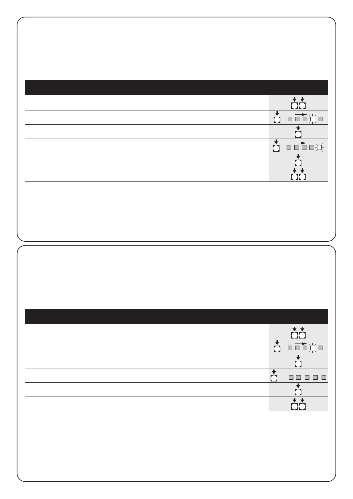
66
3s
x3
x1
3s
Beispiel für die Programmierung im ersten Niveau: Beispiel
Aktivieren der Funktion “Nach Photozelle erneut schließen” und Abschalten der Funktion “Verzögerter Öffnungsvorgang”
1. Steigen Sie in die Programmierung des ersten Niveaus ein, indem
Sie die Tasten P1 und P2 mindestens 3 Sekunden lang gedrückt halten.
2. Drücken Sie P1 dreimal bis die Leuchtanzeige auf der Anzeige EINGÄNGE Nr.4
aufblinkt (jetzt ist das Aufblinken kurz).
3. Aktivieren Sie die Funktion “Erneutes Schließen nach Foto”, indem Sie
die Taste P2 drücken (jetzt wird das Aufblinken lang sein).
4. Drücken Sie P1 einmal bis die Leuchtanzeige auf der Anzeige EINGÄNGE Nr.5
aufblinkt (jetzt ist das Aufblinken lang)
5. Schalten Sie die Funktion “Verzögerter Öffnungsvorgang” ab, indem Sie P2 drücken
jetzt wird die Anzeige kurz aufblinken)
6. Steigen Sie aus der Programmierung aus speichern Sie, indem Sie mindestens
3 Sekunden lang auf P1 und P2 drücken.
4.2.3) Beispiel für die Programmierung im ersten
Niveau
In folgenden Beispielen werden die zum Aktivieren oder Abschalten
einer Funktion im ersten Niveau nötigen Schritte beschrieben. Als
Beispiel beschreiben wir das Aktivieren der Funktion “Nach Foto
erneut schließen” und das Abschalten der Funktion “Verzögerter
Öffnungsvorgang” des Torflügels.
3s
x3
3s
x4
3s
Beispiel für die Programmierung des zweiten Niveaus: Beispiel
Die Sensibilität des Strommessers ändern
1. Steigen Sie in die Programmierung des ersten Niveaus ein, indem Sie P1 und P2
mindestens 3 Sekunden lang drücken.
2. Drücken Sie P1 dreimal bis die blinkende Leuchtanzeige auf der Anzeige
EINGÄNGE Nr. 4 aufblinkt.
3. Gehen Sie durch einen mindestens 3 Sekunden langen Druck auf P2 ins zweite
Niveau über.
4. Drücken Sie P2 viermal bis alle EINGÄNGE-Leuchtanzeigen aus sind (mit
Ausnahme des Strommessers)
5. Kehren Sie durch Druck auf P1 zum ersten Niveau zurück.
6. Steigen Sie aus der Programmierphase aus, wobei Sie durch mindestens
3 Sekunden langen Druck auf P1 und P2 speichern.
4.2.4) Beispiel für die Programmierung im
zweiten Niveau
In diesem Beispiel werden die nötigen Schritte zur Änderung eines
Parameters im zweiten Niveau beschrieben. Als Beispiel
beschreiben wir die Änderung der Sensibilität des Strommessers bis
zum “Ausschluss des Strommessers”
P2P1
P2P1
P1
4
P1
5
P2
P2P2P2
P2P1
P2P1
P1
4
P1
Page 67

67
D
HALT Foto Foto1Schrit-
tzyklus
AUX
HALT PP
Auto
Bedingung
Entnahme
Nach
Foto
Phasenverschiebung
Normaler
Betrieb
Leuchtanzeige OK
angsames Aufblinken
Erstes Niveau
Leuchtanzeige OK
ständig an
Zweites Niveau
Luchtanzeige OK
schnelles Aufblinken
51020
sekunde
40 80
PAUSENDAUER
o. p.
type 1
o. p.
type 2
ouvre
seul.
ferme
seul.
Foto 2
HILFSEINGANG (*)
246
sekunde
810
DAUER DES VORBLINKENS
1
alle Leuchtanzeigen aus ➡ Strommesser abgeschaltet
23
grad
45
SENSIBILITÄT DES STROMMESSERS
246
sekunde
810
VERZÖGERUNGSDAUER VON MOTOR1
P1+P2
3 Sek.lang
P1
3 Sek.lang
(nicht speichern)
P1+P2
3 Sek.lang
(speichern)
P2
pendant 3 s
P1
P1 P2
1
2
P1 P2
P1 P2
P1 P2
P1 P2
P1 P2
P1 P2
on
off
4.2.5) Programmierschema
In der folgenden Abbildung sehen Sie das komplette
Programmierschema der Funktionen mit den entsprechenden
Parametern.
In derselben Abbildung wurden die Funktionen und die anfänglich
gespeicherten bzw. die nach einem vollständigen Löschen des
Speichers eingegebenen Parameter angegeben.
(*)
a.p. Typ1: teilweises Öffnen Typ 1
Bewegung nur von Motor 2 (normalerweise geöffnet)
a.p. Typ2: teilweises Öffnen Typ 2, Bewegung beider Motoren die halbe
Arbeitszeit lang (normalerweise geöffnet)
nur öffnet öffnet ➔ stopp ➔ öffnet ➔ stopp....(normalerweise geöffnet)
nur schließt schließt ➔ stopp ➔ schließt ➔ stopp....
(normalerweise geöffnet)
Foto2 genutzt wie Foto 2 (normalerweise geschlossen)
Page 68

68
Die Abnahme des Automatisierungssystems muss von
qualifiziertem und erfahrenem Fachpersonal durchgeführt
werden, das die vorgesehenen Kontrollen im Hinblick auf
das vorhandene Risiko vornehmen muss.
Die Abnahme ist der wichtigste Teil der Inbetriebnahme des
Automatisierungssystems. Jedes einzelne Bestandteil wie z.B. die
Motoren, der Funkempfänger, der Notstopp, die Photozellen und
andere Sicherheitsvorrichtungen muss einzeln abgenommen
werden. Wir empfehlen, die in den jeweiligen Handbüchern
beschriebenen Schritte durchzuführen.
Die Abnahme der Steuerzentrale soll folgendermaßen durchgeführt
werden (die Abfolge bezieht sich auf die Steuerzentrale A400 mit
vorgespeicherten Funktionen).
•Überprüfen Sie, ob die Aktivierung des SCHRITTZYKLUS-
Eingangs folgende Bewegungsabfolge auslöst: Öffnen-StoppSchließen-Stopp.
•Überprüfen Sie, ob die Aktivierung des AUX-Eingangs (Funktion
des teilweisen Öffnens Typ 1) folgende Abfolge bei Motor 2
hervorruft: Öffnen, Stopp, Schließen Stopp. Der Motor 1 tritt beim
Schließen nicht in Funktion.
• Schalten Sie eine Photozelle nach der anderen, bzw. eine
Sicherheitsvorrichtung nach der anderen, ein, welche jeweils mit
den Eingängen FOTO, FOTO1 und FOTO2 verbunden sind und
überprüfen Sie, dass bei Aktivierung eines Eingangs der
Steuerzentrale kein Bewegungsmanöver ausgelöst wird.
•
Beginnen Sie mit einem Öffnungsmanöver und überprüfen Sie, ob:
– das Tor mit dem Öffnungsmanöver fortfährt, wenn FOTO in Kraft tritt.
–
das Bewegungsmanöver solange stehen bleibt bis sich FOTO1
ausklinkt, anschließend öffnet sich das Tor wieder.
–
Wenn FOTO2 in Kraft tritt, bleibt das Tor stehen, sobald sich diese
Vorrichtung einschaltet, anschließend schließt sich das Tor wieder.
•Überprüfen Sie, ob der Motor ausgeht, wenn das Tor beim Öffnen
den Endanschlag erreicht.
•
Beginnen Sie mit einem Schließvorgang und überprüfen Sie, ob:
–
das Tor stehen bleibt und sich anschließend erneut öffnet, wenn
FOTO in Kraft tritt.
–
wenn FOTO1 in Kraft tritt, das Tor solange stehen bleibt, bis
FOTO1 ausrastet und sich das Tor anschließend mit dem
Öffnungsvorgang fortfährt.
– das Tor mit dem Schließmanöver fortfährt, wenn FOTO2 in Kraft tritt.
•Überprüfen Sie, ob die Stopp-Vorrichtungen das sofortige
Anhalten des jeweiligen Bewegungsvorgangs bewirken, wenn sie
mit dem HALT-Eingang verbunden sind.
•Überprüfen Sie, ob das Niveau des Systems, das die Hindernisse
wahrnimmt, der jeweiligen Anwendung entspricht.
–
Halten Sie das Tor während des Öffnungs- bzw. Schließmanövers
an, indem Sie ein Hindernis simulieren und überprüfen Sie, ob die
Bewegungsrichtung wechselt, bevor die in den Normen
vorgeschriebene Kraft überschritten wird.
• Je nach den mit den Eingängen verbundenen Vorrichtungen
könnten weitere Kontrollen nötig werden.
Wenn bei zwei hintereinander ausgeführten Bewegungsmanövern in die
gleiche Richtung ein Hindernis zur Kenntnis genommen wird, führt die
Steuerzentrale nur 1 Sekunde lang eine teilweise Richtungsumkehrung beider
Motoren aus.
Beim darauffolgenden Kommando beginnt der Öffnungsvorgang der Türen
und das erste In-Kraft-treten des Strommessers für jeden Motor wird als
Stopp beim Öffnungsvorgang angesehen.
Dasselbe passiert bei wiederkehrender Stromversorgung des Netzes: das
erste Kommando ist immer der Öffnungsvorgang und das erste Hindernis
wird immer als Stoppvorgang beim Öffnen angesehen.
!
5) Abnahme
Die Steuerzentrale A400 erfordert als elektronisches Teil keinerlei
besondere Wartung. Überprüfen Sie jedoch von Zeit zu Zeit den
einwandfreien Betrieb der gesamten Anlage wie in Kapitel
“Abnahme” beschrieben; mindestens zweimal pro Jahr.
7) Wartung der Steuerzentrale A400
7.1) Entsorgung
Dieses Produkt besteht aus mehreren Werkstoffen, wovon einige
wieder verwertet werden können.
Informieren Sie sich, wie das Produkt vor Ort am besten nach den
gesetzlichen Normen wieder verwertet oder entsorgt werden kann.
Einige elektronische Bestandteile können die Umwelt
verschmutzen, entsorgen Sie diese auf keinen Fall in der
Natur.
!
6) Sonderzubehör
Karte RADIO
An der Steuerung befindet sich ein Verbinder für das Einstecken einer SM-Radiokarte, über die der Eingang „SCHRITTBETRIEB“ und „Aux2”
betätigt werden kann, wodurch die Steuerung über einen Sender ferngesteuert wird.
Ausgang 1 Schrittbetrieb
Ausgang 2 AUX2
Ausgang 3 nicht verwendet
Ausgang 4 nicht verwendet
Page 69

69
D
9) Technische Merkmale
Stromversorgung : Steuerzentrale A400 ➔ 230 V Wechselstrom ± 10%, 50 60 Hz
: Steuerzentrale A400/V1 ➔ 120 V Wechselstrom ± 10% 50 60 Hz
Maximaler Motorenstrom : Steuerzentrale A400 ➔ 1,2 A (mit blockiertem Rotor)
: Steuerzentrale A400/V1 ➔ 2,5 A (mit blockiertem Rotor)
Ausgang Stromversorgung der Serviceleistungen : 24 V Wechselstrom max. Strom 150mA
Ausgang Phototest : 24 V Wechselstrom max. Strom 100mA
Ausgang Blinklicht : für Blinklicht mit Netzspannung, max. Leistung 40 W
Ausgang Anzeige offenes Tor : für 24 V Wechselstrom Leuchtanzeige maximale Leistung: 1,5W
Arbeitsdauer : maximal 60 Sekunden
Pausendauer : 5, 10, 20, 40, 80 Sekunden sind programmierbar
Phasenverschiebungsdauer mit sich öffnendem Tor : 2, 4, 6, 8, 10 Sekunden sind programmierbar
Vorblinkdauer : 2, 4, 6, 8, 10 Sekunden sind programmierbar
Betriebstemperatur : -20°÷50°C
Schutzgrad des Gehäuses : IP55
Maße und Gewicht : 230 x 180 h 100 mm, ca. 1100 g
Diese Anleitungen sollen dem Installateur beim Lösen einiger allgemeiner
Probleme helfen, die während der Installation auftreten können
.
Keine Leuchtanzeige ist an:
•Überprüfen Sie, ob die Steuerzentrale an das Stromnetz
angeschlossen ist (messen Sie, ob auf den Klemmen 1-2
Netzspannung und auf den Klemmen 15-16 eine 24 V
Wechselstrom-Spannung vorhanden ist).
•Überprüfen Sie die beiden Schmelzsicherungen; sollte nicht
einmal die OK-Leuchtanzeige angeschaltet sein oder blinken,
könnte es sich um einen schwereren Schaden handeln, deshalb
muss die Steuerzentrale ausgetauscht werden.
Die OK-Leuchtanzeige blinkt regelmäßig, aber die
Leuchtanzeigen EINGÄNGE spiegeln den Zustand der
entsprechenden Eingänge nicht wider.
• Schalten Sie die Stromversorgung augenblicklich ab, um aus einer
möglichen Programmierphase auszusteigen.
•Überprüfen Sie aufmerksam die Verbindungen auf den Klemmen
13 und 23.
Die “automatische Suche” wird nicht eingeleitet
• Die “automatische Suche” tritt erst in Kraft, wenn sie vorher noch
nie ausgeführt wurde oder wenn der Speicher gelöscht wurde.
Um festzustellen, ob der Speicher leer ist, schalten Sie zuerst den
Strom ab. Wenn Sie den Strom wieder anschalten, müssen alle
Leuchtanzeigen 10 Sekunden lang schnell blinken. Wenn sie nur
3 Sekunden lang blinken, enthält der Speicher noch gültige Werte.
Wenn Sie eine neue automatische Suche ausführen möchten,
müssen Sie den Speicher vollkommen löschen.
Die “automatische Suche” wurde bisher noch nie
durchgeführt, aber der Bewegungsablauf vollzieht sich
nicht oder verläuft falsch.
• Um die automatische Suche zu aktivieren, muss die gesamte
Anlage mit allen Sicherheitsvorrichtungen, ganz besonders die
Photozellen, funktionieren, da die Photozellen während des
Photozellen-Tests überprüft werden.
• Versichern Sie sich, dass keine der mit den Eingängen
verbundene Vorrichtung sich während der automatischen Suche
einschaltet.
• Für einen korrekten Start der automatischen Suche müssen die
Leuchtanzeigen auf den Eingängen wie auf der unten
angegebenen Abbildung aufleuchten. Die OK-Leuchtanzeige
muss einmal pro Sekunde aufblinken.
Die “automatische Suche” wurde korrekt durchgeführt,
aber das Tor bewegt sich nicht.
• Überprüfen Sie, dass die Leuchtanzeigen zur Sicherheit (HALT,
FOTO, FOTO1 und eventuell FOTO2) aufleuchten und die
aktivierte Kommando-Leuchtanzeige (Schrittzyklus oder AUX) die
ganze Dauer des Kommandos über aufleuchtet.
Während der Bewegung wechselt das Tor die
Bewegungsrichtung
Folgende Gründe sind für eine Umkehrung der Bewegungsrichtung
verantwortlich:
• Ein Ansprechen der Photozellen (FOTO2 beim Öffnen, FOTO oder
FOTO1 während des Schließens); in diesem Fall kontrollieren Sie
die Verbindungen der Photozellen und überprüfen Sie eventuell
die Leuchtanzeigen der Eingänge.
•
Ein Ansprechen des Strommessers während die Motoren laufen
(also entfernt von den Endanschlägen) wird als Hindernis gedeutet
und ruft eine Richtungsänderung hervor. Zur Kontrolle, ob der
Strommesser in Kraft getreten ist, überprüfen Sie die OKLeuchtanzeige. Ein schnelles Aufblinken (im Vergleich zum normalen
Aufblinken von 1 Sekunde) zeigt an, dass das Ansprechen des
Strommessers von Motor M1 hervorgerufen wurde, zweimal
schnelles Aufblinken zeigt ein Ansprechen des Motors M2 an.
8) Was machen, wenn...
Halt Foto AuxFoto 1
Schrittz
yklus
Halt
PP
(Schrittzyklus)
ALT Foto Foto1Passo
Passo
AUX
P1 P2
ALT PP
Page 70

70
smxi Funkempfänger
Beschreibung des Produktes
Die Besonderheit dieses Funkempfängers liegt in dem
Erkennungscode, der für jeden Sender unterschiedlich ist (zudem
ändert er sich nach jedem Gebrauch). Damit der Empfänger einen
bestimmten Sender erkennt, muss der Erkennungscode gespeichert
werden. Dieser Vorgang wird für jeden Sender, der zur Steuerung der
Steuerzentrale benutzt werden soll, einzeln wiederholt.
Im Empfänger können bis max. 256 Sender gespeichert werden. Ein
einzelner Sender kann nicht gelöscht werden, die Codenummern können nur
alle gleichzeitig gelöscht werden.
-
Für fortgeschrittenere Funktionen verwenden Sie bitte das spezielle Programmierungsgerät.
In der Speicherphase der Codenummer des Senders stehen 2
Möglichkeiten zur Auswahl:
Art I. Jede Taste des Senders aktiviert den entsprechenden
Ausgang des Empfängers, d.h. die Taste 1 aktiviert Ausgang 1, Taste
2 aktiviert Ausgang 2, usw. In diesem Fall gibt es nur eine
Speicherphase für jeden Sender. Während dieser Phase ist es
unwichtig, welche Taste gedrückt wird, es wird nur eine einzige
Speicherstelle besetzt.
Art II. Jeder Taste des Senders kann ein bestimmter Ausgang des
Empfängers zugeordnet werden, z.B. Taste 1 aktiviert Ausgang 2,
Taste 2 aktiviert Ausgang 1 usw. In diesem Fall muss der Sender
gespeichert werden, indem man die gewünschte Taste für jeden
Ausgang, der aktiviert werden soll, drückt. Natürlich kann jede Taste
nur einen einzigen Ausgang aktivieren, während derselbe Ausgang
durch Drücken mehrerer Tasten aktiviert werden kann. Für jede Taste
wird nur eine Speicherstelle belegt.
Installieren einer Antenne
Für einen einwandfreien Betrieb muss der Empfänger mit einer ABFoder ABFKIT-Antenne ausgestattet werden; ohne Antenne ist die
Leistung auf wenige Meter begrenzt. Die Antenne muss so hoch wie
möglich angebracht werden; wenn Strukturen aus Metall oder
Stahlbeton vorhanden sind, installieren Sie die Antenne über diesen
Strukturen. Wenn das zur Antenne gehörige Kabel zu kurz ist,
benutzen Sie ein Koaxialkabel mit 50 Ohm Impedanz (z.B. RG58 mit
niedrigem Verlust), das Kabel darf nicht länger als 10 m.
Wenn die Antenne nicht auf einer ebenen Unterlage (Wand) montiert
wird, kann die Klemme des Geflechts geerdet werden, um eine
größere Leistung zu gewährleisten. Natürlich muss die Erdung
sachgemäß in der Nähe ausgeführt werden. Sollte die Montage einer
ABF- oder ABFKIT-Antenne unmöglich sein, können gute
Ergebnisse mit der dem Empfänger beiliegenden Leitung als
Antenne erzielt werden. Diese Leitung muss ausgebreitet, in der
vollen Länge montiert.
Page 71

Speichern einer Fernbedienung
In der Speicherphase wird jeder richtig erkannte
Sender im Empfangsbereich des Funks gespeichert.
Beachten Sie dies aufmerksam und stecken Sie eventuell
die Antenne aus, um die Leistung des Empfängers zu
reduzieren.
Die Speichervorgänge zum Speichern der Fernbedienungen sind
zeitlich begrenzt: deshalb ist es wichtig, sich den ganzen
Speichervorgang vor dem Speichern durchzulesen und zu verstehen.
Zur Durchführung des folgenden Verfahrens müssen die Taste am
Gehäuse des Funkempfängers (siehe A, Abb. 1b) und die jeweilige
Led (siehe B, Abb. 1b) links neben der Taste benutzt werden.
3s
2s
x3
2s
x3
1. Drücken Sie den Druckknopf mindestens 3 Sekunden lang
2. Wenn die Leuchtanzeige aufleuchtet, lassen Sie den Druckknopf los
3. Drücken Sie die dem 1. zu speichernden Sendekanal entsprechende Taste innerhalb von 10
Sekunden mindestens 2 Sekunden lang.
Anmerkung: Wenn richtig gespeichert wurde, leuchtet die Leuchtanzeige des Empfängers dreimal auf.
Wenn Sie weitere Sender speichern möchten, wiederholen Sie Vorgang 3 innerhalb von weiteren 10 Sekunden.
Die Speicherphase wird als beendet angesehen, wenn innerhalb von 10 Sekunden keine neuen Codenummern
eingegeben wurden
Tabelle “B1” Speichern I Beispiel
(jede Taste aktiviert den entsprechenden Ausgang des Empfängers)
1. Drücken Sie den Druckknopf auf dem Empfänger und lassen sie ihn sooft los, wie die Zahl
des gewünschten Ausgangs ist (2-mal für Ausgang Nr. 2).
2.
Überprüfen Sie, dass die Led sooft blinkt, wie die Zahl des gewünschten Ausgangs ist
(2-maliges Blinken für Ausgang Nr. 2)
3. Drücken Sie die gewünschte Taste des zu speichernden Senders innerhalb von 10 Sekunden
mindestens 2 Sekunden lang
Anmerkung: Wenn richtig gespeichert wurde, leuchtet die Leuchtanzeige des
Empfängers dreimal auf. Wenn Sie weitere Sender speichern möchten, wiederholen Sie Vorgang 3 innerhalb
von weiteren 10 Sekunden. Die Speicherphase wird als beendet angesehen, wenn innerhalb von 10 Sekunden
keine neuen Codenummern eingegeben wurden.
Tabelle “B2” Speichern Art II Beispiel
(jeder Taste kann ein bestimmter Ausgang zugeordnet werden)
RX
RXTXTX
RX
1b
x5s
1s 1s 1s
x1
1.
Drücken Sie die Taste auf dem NEUEN Sender mindestens 5 Sekunden lang, dann loslassen
2. Drücken Sie die Taste auf dem ALTEN Sender ganz langsam dreimal
3. Drücken Sie die Taste auf dem NEUEN Sender langsam einmal, dann loslassen
Anmerkung: wenn Sie weitere Sender speichern möchten, wiederholen Sie jedes Mal alle Schritte für jeden neuen Sender.
Tabelle “B3” Speichern aus Entfernung Beispiel
TX
TXTXTX
TX
TX
Speichern aus Entfernung
Ein neuer Sender kann im Speicher des Empfängers auch ohne
Drücken des Tastenfeldes gespeichert werden, wenn man eine
bereits gespeicherte und funktionierende Fernbedienung besitzt. Der
neue Sender erhält die Eigenschaften des bereits gespeicherten
Senders. Deshalb wird der neue Sender auf Art I gespeichert, wenn
der alte Sender auf Art I gespeichert ist. Dazu kann eine beliebige
Sendertaste gedrückt werden. Wenn der erste Sender auf Art II
gespeichert wurde, wird auch der neue auf Art II gespeichert;
allerdings muss auf dem ersten Sender die Taste gedrückt werden,
die den gewünschten Ausgang aktiviert und auf dem zweiten Sender
die Taste, die gespeichert werden soll. Vor der Durchführung der
einzelnen Vorgänge müssen alle Anweisungen gelesen werden. Sich
nun mit den beiden Fernbedienungen (die, in die der Code
eingegeben werden muss, werden wir mit NEU bezeichnen, die, mit
dem bereits gespeicherten Code, mit ALT) in den Aktionskreis der
Funksteuerungen (innerhalb der maximalen Reichweite) begeben
und die in der Tabelle verzeichneten Schritte durchführen.
71
D
Page 72

FLOR VERY VR FLO VERY VE SMILO
Tasten 1 – 2 - 4 2 1 – 2 - 4 2 2 - 4
Stromversorgung 12Vdc Batt. 23A 6Vdc Lithiumbatt. 12Vdc Batt. 23° 6Vdc Lithiumbatt. 12Vdc Batt. 23A
Stromaufnahme 10mA 10mA 15mA 10mA 25mA
Frequenz 433.92MHz
Betriebstemp. -40°C ÷ + 85°C
Ausgestrahlte Leistung 100µW
Löschen aller Sender
Dank folgendem Ablauf können alle Codenummern des Speichers gelöscht werden.
x3
3°
x5
1. Drücken Sie den Druckknopf des Empfängers und halten sie ihn gedrückt
2. Warten Sie bis die Leuchtanzeige angeht und anschließend wieder ausgeht,
solange, bis diese dreimal aufgeleuchtet hat.
3. Lassen Sie die Taste genau während dem 3. Mal Aufleuchten los.
Anmerkung: Wenn der Vorgang richtig ausgeführt wurde, leuchtet die Leuchtanzeige nach kurzem fünfmal auf.
Empfänger
Sender
Tabelle “B4” Löschen aller Sende Beispiel
RX
RX
SMXI SMXIS SMXIF
Kodifizierung Rolling code Rolling code 1024 Kombinationen FLO
52 bit FLOR 64 bit SMILO
Frequenz 433.92MHz
Eingangsimpedanz 52ohm
Ausgänge 4 (auf Verbinder SMXI)
Sensibilität besser als 0.5µV
Betriebstemp. -20°C ÷ + 50°C
Technische Merkmale
72
Page 73

73
D
Nice behält sich das Recht zu Änderungen an den Produkten in jedem Augenblick vor, in dem dies für nötig betrachtet wird.
Dichiarazione CE di conformita’ / EC declaration of conformity
Numero /Number : 151/SMXI Data / Date: 09/2002 Revisione / Revision: 1
Il sottoscritto Lauro Buoro, Amministratore Delegato, dichiara che il prodotto:
The undersigned Lauro Buoro, General Manager of the following producer, declares that the product:
Nome produttore / Producer name:
NICE s.p.a.
Indirizzo / Address: Via Pezza Alta 13, 31046 Z.I. Rustignè –ODERZO- ITALY
Tipo / Type: Ricevitore radio 433MHz / Radio receiver 433MHz
Modello / Model: SMXI, SMXIS, SMXIF
Soddisfa tutti i requisiti essenziali applicabili alla direttiva R&TTE5/99, articolo 10.3.
Satisfies all the technical regulations applicable to R&TTE5/99 directive, article 10.3.
Risulta conforme a quanto previsto dalle seguenti Norme armonizzate / Complies with the following Harmonised standards
Riferimento n° Edizione Titolo norma
Livello di valutazione
Reference n° Issue Regulation title Assessment level
ETS300683 1997 Radio Equipment and Systems (RES);Electromagnetic Compatibility (EMC) standard for Classe II
Short Range Devices (SRD) operating on frequencies between 9KHz and 25GHz
EN300220-3 2000 APPARATI RADIO E SISTEMI Classe I (LPD)
CARATTERISTICHE TECNICHE E METODI DI MISURA PER APPARATI RADIO TRA
25MHz A 1000MHz/Radio Equipment and Sistems- Short Range Devices-Technical
characteristics and test methods for radio equipment between 25MHz and 1000 MHz
REGOLAZIONE ALL’USO DEI DISPOSITIVI A CORTO RAGGIO/Regolating to the use of
short range devices (SRD)
EN60950 2nd ed. 1992 APPARECCHIATURE PERLA TECNOLOGIA DELL’INFORMAZIONE. SICUREZZA.
+A1: 1993 + A2: 1993 + A3: 1995 + A4: 1997 + A11: 1997 + EN41003/1993.
Il prodotto suindicato si intende parte integrante di una delle configurazioni di installazione tipiche, come riportato nei nostri cataloghi generali
The above mentioned product is meant integral part of the of one of the installation configuration as shown on our general catalogues
ODERZO, 30 September 2002 (Amministratore Delegato)
(General Manager)
Lauro Buoro
Page 74

74
Advertencias:
Este manual está destinado sólo al personal técnico
cualificado para la instalación. Ninguna información
contenida en este manual puede ser considerada de interés
para el usuario final.
Este manual se refiere a la central A400 y no se debe emplear
para otros productos.
La central A400 está destinada al accionamiento de actuadores
electromecánicos para la automatización de cancelas o puertas de
hojas de batiente. Cualquier otro uso se considera impropio y, por lo
tanto, está prohibido por las normas vigentes.
Se aconseja leer con atención, una vez como mínimo, todas las
instrucciones antes de proceder con la instalación.
!
mindy A400
Índice: pag.
1 Descripción del producto 75
2 Instalación75
2.1 Controles preliminares 75
2.2 Sujeción de la central A400 76
2.3 Instalación típica 76
2.4 Conexiones eléctricas 76
2.4.1 Esquema eléctrico 77
2.4.2 Descripción de las conexiones 77
2.4.3 Notas sobre las conexiones 78
2.4.4 Fototest 78
2.4.5 Control de las conexiones 79
2.5 Búsqueda de los topes mecánicos 79
2.5.1 Búsqueda automática 80
2.5.2
Búsqueda con sistema amperimétrico desconectado
80
3 Funciones programables 81
3.1 Funciones configuradas previamente 81
pag.
4 Programación82
4.1 Cancelación de la memoria 82
4.2 Modo de programación82
4.2.1 Programación del primer nivel: funciones 83
4.2.2 Programación del segundo nivel: parámetros 83
4.2.3 Ejemplo de programación del primer nivel 84
4.2.4 Ejemplo de programación del segundo nivel 84
4.2.5 Esquema para la programación85
5 Ensayo 86
6 Accesorios opcionales 86
7 Mantenimiento de la central A400 86
7.1 Desguace 86
8 Qué hay que hacer si… 87
9 Características técnicas 87
Apéndice:
Radiorreceptor SMXI 88
Page 75

75
E
El funcionamiento de la central A400 se basa sobre un sistema
amperimétrico que controla el esfuerzo de los motores que están
conectados a ella.
Este sistema permite detectar automáticamente los fines de carrera
y reconocer posibles obstáculos durante el funcionamiento normal
(protección antiaplastamiento).
Dicha característica hace que la instalación sea muy sencilla, puesto
que no sirve ninguna regulación.
La central está programada previamente sobre las funciones
normales requeridas; si fuera necesario, se pueden elegir funciones
más específicas a través de un procedimiento sencillo.
El comportamiento de la corriente también depende de otros factores
además que del esfuerzo, tales como: variaciones de tensión, tipo de motor,
valor del condensador de arranque, etc.. La central A400 ha sido optimada
para los motores instalados en los actuadores Wingo; otros tipos de motores
podrían provocar un funcionamiento incorrecto de la central A400.
ABCDEFG H
I
L
M
N
OPQRS
T
A Conector primario del transformador
B Relé Común
C Relé Abrir/Cerrar
D Relé motor M1
E Relé motor M2
F Fusible de baja tensión (500mA)
G Conector secundario transformador
H Microprocesador
I Enchufe para radiorreceptor
L Relé para fototest
M Led “ENTRADAS”
N Led “OK”
O Borne para antena radio
P Botones de programación
Q Bornes para entradas-salidas
R Bornes para motores y luz intermitente
S Bornes para conexión línea
T Fusible de línea (5A)
Para la seguridad del operador y para no modificar
accidentalmente la tarjeta electrónica, se puede acceder
sólo a las cajas de conexiones y a los botones de
programación de la central.
Quite la tapa sólo si fuera necesario y tras haber cortado
la alimentación eléctrica.
!
1) Descripción del producto
Recuerde que los sistemas de cancelas y puertas
automáticas tienen que ser instalados sólo por personal
técnico cualificado y respetando las normas vigentes.
Siga con atención las advertencias del fascículo:
“Advertencias para el instalador”.
!
2.1) Controles preliminares
Antes de empezar cualquier operación, controle que todo el material
sea adecuado a la instalación y de acuerdo con cuanto previsto por
las normas. Además de verificar todos los aspectos indicados en el
fascículo “Advertencias para el instalador”, en esta parte indicamos
una lista de controles específicos para la central A400.
• Los “topes mecánicos de carrera” deben ser adecuados para
detener el movimiento de la puerta y deben amortiguar sin
problemas toda la energía cinética acumulada en el movimiento
de la hoja.
• Alimente la central con un cable de 3 x 1,5 mm
2
. Si la distancia
entre la central y la conexión a la instalación de tierra fuera
superior a 30 m, hay que instalar una placa de conexión a tierra
cerca de la central.
• En las conexiones de las piezas de baja tensión de seguridad use
cables de sección mínima de 0,25 mm
2
.
Use cables de conductores encerrados si la longitud es superior
a 30 m, conectando el cable de masa sólo del lado de la central.
• No conecte los cables en cajas enterradas, incluso si fueran
completamente herméticas.
• Si la central está instalada correctamente, garantiza un grado de
protección IP55, es decir, adecuada para ser instalada en
exteriores.
• Fije la central sobre una superficie firme, plana y bien protegida
contra los golpes, procurando que la parte inferior quede a 40 cm
del piso como mínimo.
• Coloque arandelas aislantes para cables y pasadores para tubos
sólo en la parte inferior de la caja (véanse figura 1, figura 1a).
2) Instalación
Page 76

76
2.3) Instalación típica
A fin de aclarar algunos términos y algunos aspectos de una
instalación de automatización para puertas o cancelas de 2 hojas de
batiente, damos un ejemplo típico:
Recordamos en particular que:
• Todas las fotocélulas fabricadas por NICE disponen del sistema
de SINCRONISMO, que permite eliminar el problema de la
interferencia entre dos pares de fotocélulas (para mayores
aclaraciones véanse las instrucciones de las fotocélulas).
• El par de fotocélulas “FOTOCÉLULA” en apertura no tiene efecto,
mientras que provoca una inversión durante el cierre.
• El par de fotocélulas “FOTOCÉLULA1” bloquea la maniobra tanto
en apertura como en cierre.
• El par de fotocélulas “FOTOCÉLULA2” (conectado a la entrada
AUX oportunamente programada) durante cierre no tiene efecto
mientras que provoca una inversión durante la apertura.
2.2) Sujeción de la central A400
La caja protege la tarjeta electrónica de contactos accidentales. Sólo si fuera necesario es posible trabajar sobre la tarjeta actuando
como muestra la figura 1a.
Para facilitar el taladrado de la caja en la parte inferior, baje el fondo
de plástico, como indicado en la referencia 1 figura 1a.
2.4) Conexiones eléctricas
Para garantizar la seguridad del instalador y no averiar
los componentes, mientras se efectúan las conexiones
eléctricas, o se conecta el radiorreceptor, la central debe
estar completamente apagada.
• Las entradas de los contactos tipo NC (Normalmente Cerrado)
que no se utilicen se tienen que conectar al "Común 24V " por
medio de un conector puente (excluidas las entradas de las
fotocélulas; para más aclaraciones véase la función FOTOTEST).
• Si para la misma entrada hay varios contactos NC, se deben
conectar en serie entre sí.
• Si las entradas de los contactos tipo NA (Normalmente Abierto) no
se utilizan, se tiene que dejar libres.
• Si para la misma entrada hay varios contactos NA se conectan en
PARALELO entre sí.
• Los contactos tienen que ser exclusivamente mecánicos y sin
ningún potencial; no se admiten conexiones de configuración
como aquéllas definidas “PNP”, “NPN”, “Open Collector”, etc.
• Los motores WINGO tienen incorporado el condensador
necesario para el funcionamiento.
!
1 1a
FOTO 1
FOTO
FOTO 2
6
7
1
1
4
2
3
5
1.Actuadores electromecánicos
2.Luz intermitente
3.Central “A400”
4.Selector de llave
5.
Par de fotocélulas “FOTOCÉLULA”
6.
Par de fotocélulas “FOTOCÉLULA1”
7.
Par de fotocélulas “FOTOCÉLULA2”
Ref 1
Page 77

77
E
2.4.1) Esquema eléctrico
1
LN
M1 M2
2
5 6 7 8 9 101112 1314 151617181920212223
24 25
34
P1
ALT
LED OK
P2
PP
ALIMENTACIÓN
LUZ INTERMITENTE
ANTENA
ABRIR
COMÚN
CERRAR
ABRIR
COMÚN
CERRAR
COMÚN 24V
24V
0
0
24V TX FOTOCÉLULA
SCA 24 Vca
STOP (NC)
FOTOCÉLULA (NC)
FOTOCÉLULA 1 (NC)
PASO A PASO (NA)
AUX (NX)
FOTOTEST
24Vac
2.4.2) Descripción de las conexiones
Damos una descripción breve de las posibles conexiones de la central hacia el exterior.
Bornes Funciones Descripción
1÷3 AlimentaciónLínea de alimentación desde red
4 Tierra Conexión a tierra de los motores
5÷6 Luz intermitente Conexión de la luz intermitente a tensión de red (máx. 40W)
7÷9 Motor 1 *Conexión del motor M1 (hoja inferior)
10÷12 Motor 2 *Conexión del motor M2 (hoja superior)
13÷14 Fototest Alimentación TX fotocélulas (24 Vca máx. 100 mA)
15÷16 24 Vca Alimentación servicios, RX fotocélulas, etc. (24 Vca máx. 150 mA)
17 Común 24 Vca Común para todas las entradas/salidas
18 SCA Indicador luminoso Cancela Abierta (24Vca máx. 1,5W)
19 Stop Entrada NC con función de STOP (emergencia, bloqueo de seguridad)
20 Fotocélula Entrada NC para dispositivos de seguridad (fotocélulas, bordes neumáticos)
21 Fotocélula 1 Entrada NC para dispositivos de seguridad (fotocélulas, bordes neumáticos)
22 Paso a paso Entrada para funcionamiento cíclico (ABRIR - STOP - CERRAR - STOP)
23 AUX ** Entrada auxiliar
24÷25 Antena Entrada para la antena del radiorreceptor
* Con 2 motores, el primero que se mueve para la apertura es el motor M2.
La central A400 reconoce automáticamente si hay un solo motor instalado que se deberá conectar a M2.
** La entrada auxiliar AUX se puede programar en una de estas funciones (véase capítulo 4 “Programación”)
Función Tipo entrada Descripción
ABRIR PARCIAL tipo 1 NA Abre completamente la hoja conectada al motor M2
ABRIR PARCIAL tipo 2 NA Abra las 2 hojas hasta la mitad de la carrera
ABRIR NA Ejecuta sólo la maniobra de apertura
CERRAR NA Ejecuta sólo la maniobra de cierre
FOTOCÉLULA 2 NC Función FOTOCÉLULA 2
DESCONECTADO -- Ninguna función
Si no se ha programado de otra manera, la entrada AUX cumple la función ABRIR PARCIAL tipo 1
STOP
ATENCIÓN: conexión fotocélulas con Fototest (véase cap. 2.4.4)
Nota: central preprogramada y preparada para medir automáticamente el tiempo de funcionamiento (véase cap. 2.5.1)
Page 78

78
La mayoría de las conexiones es muy sencilla, una gran cantidad
son conexiones directas a un solo usuario o contacto. En las
siguientes figuras se indican algunos ejemplos sobre cómo conectar
los dispositivos exteriores.
2.4.3) Notas sobre las conexiones
12345
12345
12345
12
12
12
LED OK
TX
FOTO
FOTO1
FOTO 2
RX
TX RX
TX RX
13
P1 P2 24 25
14 15 16 17 18 19 20 21 22 23
13
TX
FOTO
1 123452
LED OK
P1 P2 24 25
RX
14 15 16 17 18 19 20 21 22 23
La central A400 dispone de serie de una función de FOTOTEST,
que es una solución ideal en términos de fiabilidad para los
dispositivos de seguridad y permite lograr, para el grupo de la central
y de los dispositivos de seguridad, la “categoría 2” según la norma
UNI EN 954-1 (edic. 12/1988).
Cada vez que se pone en marcha una maniobra, se controlan todos
los dispositivos de seguridad y sólo si el ensayo tuvo resultados
positivos, empieza la maniobra. Todo esto es posible sólo
empleando una configuración especial en las conexiones de los
dispositivos de seguridad; prácticamente, los transmisores de las
fotocélulas “TX” están alimentados por separado respecto de los
receptores “RX”.
Además, la función SINCRONISMO (disponible en todas las
fotocélulas NICE) es el único método para garantizar que dos pares
de fotocélulas no interfieran entre sí.
Las entradas sujetas al procedimiento de fototest son FOTOCÉLULA,
FOTOCÉLULA1 y la entrada AUX si está configurada como FOTOCÉLULA2.
La etapa de fototest se realiza al comienzo de cada maniobra y no se puede
desconectar, es decir que si una de estas entradas no se utiliza, es necesario
conectarla al borne n°13, véanse las figuras siguientes para los ejemplos de
conexión.
2.4.4) Fototest
Parpadeo lento indica la apertura.
Parpadeo veloz indica el cierre.
Encendido continuo indica cancela
abierta.
Esquema de conexión de las fotocélulas FOTOCÉLULA,
FOTOCÉLULA1 y FOTOCÉLULA2.
Esquema de conexión con la fotocélula “FOTOCÉLULA” sola
Ejemplo 1
Cómo conectar el selector para
ejecutar las funciones PASO A
PASO y STOP.
Ejemplo 2
Cómo conectar el selector para
ejecutar las funciones PASO A
PASO y una de las funciones
previstas para la entrada auxiliar
(PEATONAL, SÓLO ABRIR,
SÓLO CERRAR, etc.).
Ejemplo de conexión de una radio
exterior alimentada a 24Vca.
1° Canal
➔
PASO A PASO
2° Canal
➔
AUX
Conexión del Indicador luminoso C.A.
Conexiones para una radio exterior
Conexión del selector de llave
2 3
PASO A
PASO
STOP
PASO A
PASO
AUX
24V
17
18
1,5W
1
15
16
22
17
23
12
24V
0V
2345612
PASSO
PASSO
COM
NA NC
17
22
19
17
PASSO
PASSO
COM COM
NA NA
17
22
23
17
ALT
COM
AUX
Page 79

79
E
Ejemplos unifilares de conexiones de las fotocélulas
Conexión de la fotocélula “FOTOCÉLULA” sola.
(referencia fig. 2)
Nota: la entrada FOTOCÉLULA1 (21) no se utiliza, es decir que se
debe conectar al borne 13 para permitir la función FOTOTEST a la
FOTOCÉLULA sola.
Conexión de FOTOCÉLULA y FOTOCÉLULA1
Nota: respete las conexiones de alimentación indicadas y active la
función SINCRONISMO (disponible en todas las fotocélulas NICE).
Conexión de FOTOCÉLULA, FOTOCÉLULA1 y FOTOCÉLULA2
(referencia fig. 3)
Nota: respete las conexiones de alimentación indicadas y active la
función SINCRONISMO (disponible en todas las fotocélulas NICE).
12345
12
TX
FOTO
RX
13
14
13
15
16
17
20
21
12345
12
12345
12
FOTO
FOTO 1
TX RX
TX RX
13
14
14
13
15
16
17
20
16
15
17
21
12345
12
12345
12
12345
12
FOTO
TX RX
FOTO 1
TX RX
FOTO 2
TX RX
13
14
14
13
14
13
15
16
17
20
16
15
17
21
16
15
17
23
2.4.5) Control de las conexiones
Las siguientes operaciones se efectúan con los
circuitos bajo tensión; algunas piezas están bajo tensión
de red, es decir, ¡MUY PELIGROSAS!. Tenga mucho
cuidado en lo que está haciendo y NUNCA TRABAJE
SÓLO.
Una vez que haya finalizado las conexiones previstas para la
automatización, es posible realizar los controles.
• Alimente la central y controle que todos los Leds parpadeen
rápidamente por algunos segundos.
• Controle que en los bornes 1-2 haya tensión de red y que en los
bornes 15-16 haya una tensión de alrededor de 24Vca; si dichos
valores no corresponden, corte inmediatamente la alimentación y
controle con mayor atención las conexiones y la tensión de
alimentación.
• Tras el parpadeo veloz inicial, el Led “OK” indica que la central
funciona correctamente con un parpadeo regular con una
cadencia de un segundo. Cuando en las entradas hay una
variación, el Led “OK” efectúa dos parpadeos rápidos, que
indican que se ha reconocido la entrada.
• Si las conexiones son correctas, las entradas tipo NC, es decir
STOP, FOTOCÉLULA, FOTOCÉLULA1, deben tener el Led
correspondiente encendido. Los Leds de PASO A PASO y AUX
deben estar apagados (si está presente FOTOCÉLULA2 y AUX
programado correctamente, el Led AUX tiene que estar
encendido).
• Controle que actuando sobre los dispositivos conectados a las
entradas se apaguen y enciendan los Leds correspondientes.
!
2.5) Búsqueda de los topes mecánicos
Finalizados los controles, puede empezar la etapa de búsqueda
automática de los topes mecánicos; dicha operación es necesaria
porque la central A400 debe “medir” los tiempos de duración de las
maniobras de apertura y cierre
Si la central no se ha instalado nunca, es decir que en la memoria de la
central todavía no hay ningún tiempo válido, el procedimiento se activa
automáticamente. En cambio, si esta operación ya ha sido ejecutada, para
poderla reactivar, primero hay que cancelar la memoria (véase el capítulo
“Programación - Cancelación de la memoria”). Para comprobar si la memoria
contiene tiempos, apague y vuelva a encender la alimentación de la central;
si todos los Leds parpadean rápidamente por 10 segundos, la memoria está
vacía; si el parpadeo dura sólo 3 segundos significa que la memoria ya
contiene los tiempos de funcionamiento de los motores.
STOP Foto-
c lula
Foto-
c lula
Paso a
Paso
1
AUX
P1 P2
STOP PP
Page 80
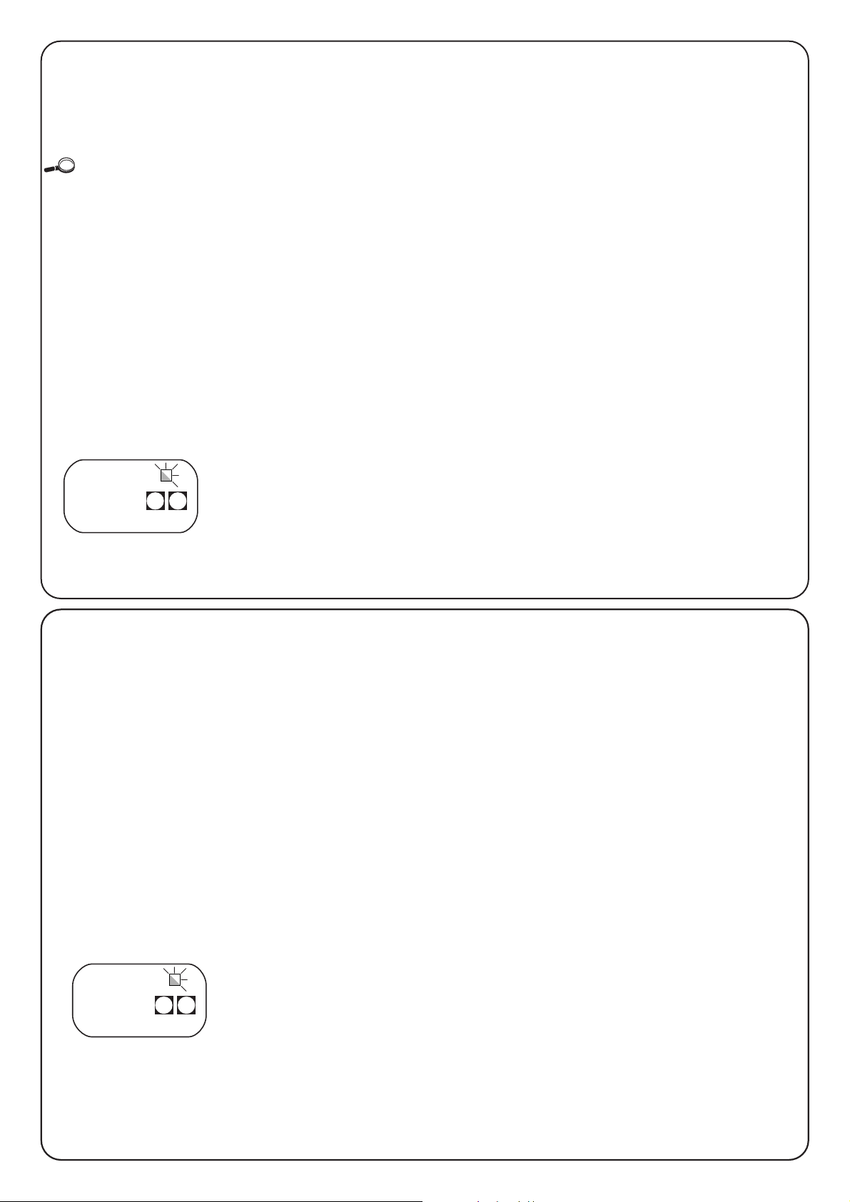
80
2.5.2) Búsqueda con sistema amperimétrico
desconectado
Cuando el sistema de detección amperimétrico no reacciona
correctamente, es posible hacer funcionar la central sólo por tiempo,
desconectando completamente la función amperimétrica (véase la
sección “Programación parámetros y funciones” para desconectar
el sistema amperimétrico).
En este caso el instalador de “advertir” a la central que ha alcanzado
el tope mecánico.
• Antes de empezar la búsqueda con el sistema amperimétrico
desconectado, controle que todos los dispositivos de seguridad
den la autorización correspondiente (STOP, FOTOCÉLULA y
FOTOCÉLULA1 activos).
• Las hojas pueden estar en cualquier posición, pero es preferible
que estén a alrededor de la mitad de la carrera.
• Oprima el botón PP que acciona la etapa de búsqueda,
que consisten en:
– Apertura breve, primero M2, luego M1.
Si los motores no arrancan para la apertura, o el primero que se
mueve no es M2, bloquee la búsqueda oprimiendo el botón STOP
y controle las conexiones de los motores.
– Cierre del motor M1 hasta el tope mecánico de cierre.
• Oprima PP cuando M1 haya alcanzado el tope mecánico
de cierre.
– Cierre del motor M2 hasta el tope mecánico de cierre.
• Oprima PP cuando M2 haya alcanzado el tope mecánico
de cierre.
– Transcurrido un instante, empieza la maniobra de apertura del
motor M2.
• Oprima PP cuando M2 haya alcanzado el tope mecánico
de apertura.
– Transcurrido un instante, empieza la maniobra de apertura del
motor M1.
• Oprima PP cuando M1 haya alcanzado el tope mecánico
de apertura.
– Transcurrido un instante, empieza una maniobra completa de
cierre.
Los motores pueden arrancar en momentos diferentes, la
finalidad es llegar al cierre manteniendo una desincronización
idónea para evitar el peligro de aplastamiento entre las hojas.
– Fin del procedimiento con memorización de todos los tiempos
medidos.
Todas estas etapas se deben llevar a cabo una después de otra sin
que el operador intervenga, oprimiendo PP sólo en los momentos
previsto. Si el procedimiento no avanza correctamente, es necesario
interrumpirlo oprimiendo el botón STOP. La activación de un
dispositivo de seguridad, o la llegada de un mando durante el
procedimiento, provoca la interrupción inmediata.
2.5.1) Búsqueda automática
Este procedimiento es completamente automático y se basa sobre
la medición del esfuerzo de los motores para la detección de los
topes mecánicos de apertura y cierre.
En automatizaciones “muy difíciles” puede suceder que el sistema de
detección de la variación de corriente de los motores no reaccione como
debe; pruebe a modificar el nivel de accionamento del sistema amperimétrico
o utilice un funcionamiento sólo por tiempo, véase la sección “búsqueda con
sistema amperimétrico desconectado”.
• Antes de empezar la búsqueda automática, compruebe que
todos los dispositivos de seguridad den la autorización (STOP,
FOTOCÉLULA y FOTOCÉLULA1 activos).
La activación de un dispositivo de seguridad, o la llegada de un
mando durante el procedimiento, provoca la interrupción
inmediata.
• Las hojas pueden estar en cualquier posición, pero es preferible
que estén a alrededor de la mitad de la carrera.
• Oprima el botón PP que acciona la etapa de búsqueda,
que consisten en:
– Apertura breve, primero M2, luego M1.
Si los motores no arrancan para la apertura, o el primero que se
mueve no es M2, bloquee la búsqueda oprimiendo el botón STOP
y controle las conexiones de los motores.
– Cierre del motor M1 hasta el tope mecánico de cierre.
– Cierre del motor M2 hasta el tope mecánico de cierre.
– Comienzo de la apertura de los motores M2.
– Tras la desincronización prevista, empieza la apertura del motor
M1.
Si la desincronización no es suficiente, bloquee la búsqueda
oprimiendo el botón STOP y modifique el tiempo (véase capítulo
“Programación”).
– Medición del tiempo necesario para que los motores alcancen los
topes mecánicos de apertura.
– Maniobra completa de cierre.
Los motores pueden arrancar en momentos diferentes, la
finalidad es llegar al cierre manteniendo una desincronización
idónea para evitar el peligro de aplastamiento entre las hojas.
– Fin del procedimiento con memorización de todos los tiempos
medidos.
Todas estas etapas se deben llevar a cabo una después de otra sin
que el operador intervenga. Si así no fuera, el procedimiento no
avanza correctamente y es necesario interrumpirlo oprimiendo el
botón STOP. Controle las conexiones y repita el procedimiento,
modificando, si fuera necesario, los umbrales de desconexión del
sistema amperimétrico (véase el capítulo “Programación”).
P1 P2
ALT PP
P1 P2
ALT PP
Page 81

81
E
La central A400 permite programar algunas funciones y parámetros
para que la instalación sea más adecuada a las exigencias del
usuario y más seguras en cualquier condición de empleo.
Función “Automático”:
Esta función prevé un cierre automático después del tiempo de
pausa programado; inicialmente, el tiempo de pausa está
configurado en 20 segundos, pero se puede modificar en 5, 10, 20,
40, 80 segundos.
Función “Uso comunitario”:
Esta función es útil cuando muchas personas usan la automatización
con un mando por radio. Si esta función está activa, cada mando
recibido provoca una maniobra de apertura que no se puede
interrumpir por otros impulsos de mando, excepto por aquellos de
emergencia / seguridad (STOP, FOTOCÉLULA 1, FOTOCÉLULA 2) y
de cierre inmediato (AUX configurado como “Sólo cerrar”).
Parpadeo previo:
La función permite activar la luz intermitente antes del comienzo de la
maniobra por el tiempo programable entre 2, 4, 6, 8, 10 segundos.
Cierre 4 segundos después de fotocélula:
Con el cierre automático, la función permite disminuir el tiempo de
pausa a 4 segundos después de que la fotocélula “FOTOCÉLULA”
queda libre, es decir que la puerta se cierra 4 segundos después de
que el usuario ha pasado.
Desincronización hojas:
Esta función provoca durante la apertura un retardo en la activación
del motor M1 respecto de M2, que sirve para evitar que las hojas
puedan encastrarse. La desincronización durante el cierre siempre
está presente (requerida por las normas de seguridad) y la calcula
automáticamente la central para obtener la misma desincronización
programada durante la apertura.
Sensibilidad amperimétrica:
La central tiene un sistema para medir la corriente absorbida por los
motores, que se usa para detectar los topes mecánicos y posibles
obstáculos durante el movimiento de la puerta. Puesto que la corriente
absorbida depende de diversas condiciones (peso de la puerta,
fricciones varias, ráfagas de viento, variaciones de tensión, etc.) se ha
previsto la posibilidad de modificar el umbral de accionamiento.
Se han previsto cinco niveles: grado 1 es el más sensible, grado 5
es el menos sensible. Inicialmente está configurado en grado 2 que
debería ser ideal para la mayoría de las instalaciones.
Entrada auxiliar AUX:
La central prevé una entrada auxiliar que se puede configurar en una
de las siguientes funciones:
• Apertura parcial tipo 1: ejecuta la misma función que la
entrada PASO A PASO provocando la apertura sólo del motor M2.
Funciona sólo con la cancela cerrada completamente; en caso
contrario, el mando es interpretado como si fuera un mando
PASO A PASO.
• Apertura parcial tipo 2: ejecuta la misma función que la
entrada PASO A PASO provocando la apertura de las dos hojas
por la mitad del tiempo previsto para la apertura total. Funciona
sólo con la cancela cerrada completamente; en caso contrario, el
mando es interpretado como si fuera un mando PASO A PASO.
• Sólo abrir: esta entrada ejecuta sólo la apertura con la secuencia
Abrir-Stop-Abrir-Stop.
• Sólo cerrar: esta entrada ejecuta sólo el cierre con la secuencia
Cerrar-Stop-Cerrar-Stop.
• Fotocélula 2: ejecuta la función del dispositivo de seguridad
“FOTOCÉLULA 2”.
• Excluida: la entrada no tiene ninguna función.
El principio de funcionamiento del sistema
amperimétrico se basa sobre las variaciones de corriente
absorbidas por los motores. Si al comienzo de la maniobra
el motor está bloqueado porque la hoja ya está en el tope
mecánico, no se producirá ninguna variación de corriente
y, por consiguiente, el obstáculo no será detectado.
La función “amperimétrica” regulada oportunamente
(junto con otras soluciones indispensables) puede ser útil
para la observancia de las normas europeas EN 12453 y
EN 12445, que requieren el uso de técnicas o dispositivos
para limitar las fuerzas y el peligro en el movimiento de las
puertas y cancelas automáticas.
Si fuera necesario, es posible desconectar la función amperimétrica y
hacer funcionar la central sólo por tiempo, para ello véase el capítulo
“Búsqueda con sistema amperimétrico desconectado”.
Si se desconecta el sistema amperimétrico, los
motores continúan a “toda fuerza” durante toda la
maniobra.
Analice con atención los riesgos y prevea posibles
elementos de seguridad en la instalación para lograr los
niveles de seguridad previstos por las normativas.
!!!
3) Funciones programables
3.1) Funciones configuradas previamente
La central A400 cuenta con algunas funciones programables (véase
capítulo “Funciones programables”). Tras la etapa de búsqueda,
dichas funciones se configuran previamente en una configuración
típica que satisface la mayoría de las automatizaciones.
• Cierre automático : después de 20 segundos
• Desincronización de las hojas : 4 segundos
• Parpadeo previo : desactivado
• Entrada auxiliar : apertura parcial tipo 1
(activa sólo el motor M2)
• Sensibilidad amperimétrica : Grado 2
Las funciones se pueden cambiar en cualquier momento, tanto
primero como después de la etapa de búsqueda, a través de un
procedimiento de programación.
Page 82

82
4.2) Modo de programación
Para todas las etapas de programación se utilizan sólo los dos
botones P1 y P2 que están en la tarjeta.
Además, los 5 leds “ENTRADAS”, que generalmente indican el
estado de las entradas, en este caso indican el “parámetro”
seleccionado.
Ejemplo:
Se han previsto 2 niveles de programación:
• En el primer nivel se pueden activar o desactivar las funciones.
Cada Led ENTRADAS corresponde a una función; si el Led está
encendido, la función está activa, mientras que si está apagado,
la función está desactivada.
L
ed 1 : Función “Automático”
L
ed 2 : Función “Uso comunitario”
L
ed 3 : Parpadeo previo
L
ed 4 : Cerrar después de fotocélula
L
ed 5 : Retardo de apertura
• Desde el primer nivel se puede pasar al segundo nivel en donde
se puede elegir el parámetro correspondiente a la función; a cada
Led corresponde un valor diferente que se ha de asociar al
parámetro
4.1) Cancelación de la memoria
Cada programación nueva sustituye las configuraciones anteriores;
por consiguiente, generalmente no es necesario “cancelar todo”.
De todas maneras, con esta operación sencilla se puede cancelar
totalmente la memoria:
Tras la cancelación de la memoria hay que buscar de
nuevo los topes mecánicos, mientras que todas las
funciones vuelven a los valores configurados previamente.
!
Primer nivel:
Led. 1 Led 2 Led 3 Led. 4 Led 5
Función Función Parpadeo Cerrar 4 segundos Retardo de
“Automático”
“
Uso comunitario” previo después de fotocélula apertura
Segundo nivel:
Parámetro: Parámetro: Parámetro: Parámetro: Parámetro:
Tiempo pausa Entrada AUX Tiempo parpadeo sensibilidad Tiempo retardo
previo amperimétrica
Led 1 : 5 s Led 1 : Abrir parcial tipo 1 Led 1 : 2 s Led 1 : Grado 1 Led 1 : 2 s
Led 2 : 10 s Led 2 : Abrir parcial tipo 2 Led 2 : 4 s Led 2 : Grado2 Led 2 : 4 s
Led 3 : 20 s Led 3 : Sólo Abrir Led 3 : 6 s Led 3 : Grado 3 Led 3 : 6 s
Led 4 : 40 s Led 4 : Sólo Cerrar Led 4 : 8 s Led 4 : Grado 4 Led 4 : 8 s
Led 5 : 80 s Led 5 : Fotocélula 2 Led 5 : 10 s Led 5 : Grado 5 Led 5 : 10 s
Leds apagados: Leds apagados:
entrada desconectada
sistema amperimétrico desconectado
Grado 1 = más sensible
Grado 5 = menos sensible
Todas las funciones descritas en el capítulo “Funciones
programables” se pueden elegir a través de una etapa de
programación que finaliza con la memorización de las elecciones
realizadas.
En la central hay una memoria que conserva las funciones y los
parámetros correspondientes a la automatización.
4) Programación
3s
Tabla “A1” Para cancelar la memoria Ejemplo
1. Apague la alimentación de la central
2. Oprima y mantenga apretados los botones P1 y P2 en la tarjeta
3. Encienda la alimentación de la central
4. Espere 3 segundos como mínimo y luego suelte los dos botones
Nota: si se ha cancelado correctamente la memoria todos los leds se apagan por 1 segundo
12345
P1 P2
P2P1
P2P1
En este caso está activa la
función “Automático”, el
parpadeo previo y el
retardo de apertura del
motor M1.
Page 83

83
E
3s o bien 60s,
o bien
P1
3s
3s
1. Entre en la programación del primer nivel
(oprimiendo P1 y P2 por 3 segundos como mínimo).
2. Seleccione la función, oprimiendo P1 hasta colocar el Led intermitente en el punto deseado
3. Entre en el segundo nivel manteniendo apretado el botón P2 por 3 segundos como mínimo.
3s o bien 60s,
o bien
1. Oprima P1 por 3 segundos como mínimo, o bien espere 1 minuto, o apague la alimentación.
4.2.1) Programación del primer nivel: funciones
En el primer nivel se pueden activar o desactivar las funciones.
En el primer nivel el Led OK está siempre encendido; los Leds
ENTRADAS encendidos indican las funciones activas, mientras que
aquellos apagados indican las funciones desactivadas.
El Led intermitente indica la función seleccionada; si el parpadeo es
breve, la función está desactivada, mientras que si el parpadeo es
prolongado la función está activa.
3s
Tabla “B1” Para entrar en la programación del primer nivel: Ejemplo
1. Mantenga apretados los botones P1 y P2 por 3 segundos como mínimo.
Un parpadeo veloz de todos los Leds indica que se ha entrado en la etapa de programación.
3s
1. Oprima varias veces P1 hasta colocar el Led intermitente sobre la función deseada.
2. Oprima P2 para activar o desactivar la función. Si el parpadeo es breve la función está
desactivada, mientras que si es prolongado la función está activa.
Tabla “B3” Para salir del primer nivel confirmando las modificaciones: Ejemplo
1. Mantenga apretados los botones P1 y P2 por 3 segundos como mínimo.
Tabla “B4” Para salir del primer nivel anulando las modificaciones: Ejemplo
1. Oprima P1 por 3 segundos como mínimo, o bien espere 1 minuto, o apague la alimentación.
P2P1
P2P1
P1
P2
Tabla “B2” Para activar o desactivar una función: Ejemplo
Tabla “C5” Para salir del primer nivel anulando las modificaciones: Ejemplo
(incluso aquellas del segundo nivel)
P2P1
4.2.2)
P
rogramación del segundo nivel: parámetros
En el segundo nivel se puede elegir el parámetro correspondiente a
la función. El segundo nivel se alcanza sólo pasando por el primer
nivel.
En el segundo nivel el Led OK parpadea rápidamente, mientras
que los Leds ENTRADAS indican el parámetro seleccionado.
Tabla “C1” Para entrar en la programación del segundo nivel: Ejemplo
Tabla “C2” Para elegir el parámetro: Ejemplo
1. Oprima varias veces P2 hasta colocar el Led sobre el parámetro deseado
Tabla “C3” Para volver al primer nivel: Ejemplo
1. Oprima P1.
3s
Tabla “C4” Para salir del primer nivel confirmando las modificaciones: Ejemplo
(incluso aquellas del segundo nivel)
1. Mantenga apretados los botones P1 y P2 por 3 segundos como mínimo.
P2P1
P1
P2
P1
P2
P1
Page 84

84
3s
x3
x1
3s
Ejemplo de programación del primer nivel: Ejemplo
activar la función “Cerrar después de fotocélula” y desactivar el “Retardo de apertura”
1. Entre en la programación del primer nivel, oprimiendo P1 y P2 por 3 segundos como mínimo.
2. Oprima 3 veces P1 hasta colocar el Led intermitente sobre el Led ENTRADAS N°4
(ahora el parpadeo es breve)
3. Active la función “Cerrar después de fotocélula” oprimiendo P2
(ahora el parpadeo es prolongado)
4. Oprima 1 vez P1 para colocar el Led intermitente sobre el Led ENTRADAS N°5
(ahora el parpadeo es prolongado)
5. Desactive la función “Retardo de apertura” oprimiendo P2
(ahora el parpadeo es breve)
6. Salga de la programación memorizando, oprimiendo P1 y P2 por 3 segundos como mínimo.
4.2.3) Ejemplo de programación del primer nivel
En estos ejemplos se indican los pasos que hay que seguir para
activar o desactivar una función en el primer nivel; como ejemplo, se
activará la función “Cerrar después de fotocélula” y se desactivará el
“Retardo de apertura” de las hojas.
3s
x3
3s
x4
3s
Ejemplo de programación del segundo nivel: Ejemplo
modificar la “sensibilidad del sistema amperimétrico”
1. Entre en la programación del primer nivel, oprimiendo P1 y P2 por 3 segundos como mínimo.
2. Oprima 3 veces P1 hasta colocar el Led intermitente sobre el Led ENTRADAS N°4
3. Pase al segundo nivel oprimiendo P2 por 3 segundos como mínimo.
4. Oprima 4 veces P2 hasta que todos los Leds ENTRADAS estén apagados
(sistema amperimétrico desconectado)
5. Vuelva al primer nivel oprimiendo P1
6. Salga de la programación memorizando, oprimiendo P1 y P2 por 3 segundos como mínimo.
4.2.4) Ejemplo de programación del segundo nivel
En este ejemplo indicamos los pasos necesarios para modificar un
parámetro en el segundo nivel; como ejemplo se modificará la
sensibilidad del sistema amperimétrico hasta “sistema
amperimétrico desconectado”.
P2P1
P2P1
P1
4
P1
5
P2
P2P2P2
P2P1
P2P1
P1
4
P1
Page 85

85
E
P1 P2
P1 P2
P1 P2
P1 P2
P1 P2
P1 P2
on
off
4.2.5) Esquema para la programación
En la siguiente figura, se indica el esquema completo de la
programación de las funciones y de los parámetros
correspondientes.
En la misma figura también se indican las funciones y los parámetros
configurados previamente antes o después de una cancelación
completa de la memoria.
(*)
a.p. Tipo 1: apertura parcial tipo 1. movimiento del motor 2 (N.A.) solo
a.p. Tipo 2: apertura parcial tipo 2, movimiento de ambos motores para
1/2 del tiempo de trabajo (N.A.)
sólo abrir abrir ➔ stop ➔ abrir ➔ top .... (N.A.)
sólo cerrar cerrar ➔ stop ➔ cerrar ➔ stop .... (N.A.)
Fotocélula 2 utilizada como fotocélula 2 (N.C.)
Funcionamiento
Normal
Led OK
parpadeo lento
Primer nivel
Led OK
encendido continuo
Segundo nivel
Led OK
parpadeo veloz
P1+P2
por 3 seg.
P2
por 3 seg.
P1
P1
no memorizar
P1+P2
memorizar
TIEMPO DE PAUSA
ENTRADA AUXILIAR (*)
TIEMPO DE PARPADEO PREVIO
SENSIBILIDAD AMPERIMÉTRICA
TIEMPO RETARDO MOTOR 1
todos los Leds apagados ➔ sistema amperimétrico desconectado
Auto
Comunitario Parpade
previo
desincro
nización
Cerrar
desp.
fotocélula
segundos
a.p.
tipo 1
a.p.
tipo 2
sólo
abrir
sólo
cerrar
Foto 2
segundos
segundos
grado
STOP AUX
PASO A
PASO
FOTO-
CÉLULA
FOTO-
CÉLULA 1
STOP
PASO A
PASO
Page 86

86
El ensayo de la automatización tiene que ser
efectuado por personal cualificado y experto que deberá
establecer los ensayos previstos de acuerdo con el riesgo
presente.
El ensayo es la parte más importante de toda la etapa de realización
de la automatización.
Cada componente, por ejemplo motores, radiorreceptores,
dispositivo de parada de emergencia, fotocélulas y demás
dispositivos de seguridad, pueden requerir un ensayo específico;
por consiguiente, se aconseja seguir los procedimientos indicados
en los manuales de instrucciones respectivos.
Para el ensayo de la central A400, ejecute el siguiente procedimiento
(la secuencia se refiere a la central A400 con las funciones
configuradas previamente).
• Controle que la activación de la entrada PASO A PASO provoque
la secuencia de movimiento: Abrir, Stop, Cerrar, Stop.
• Controle que la activación de la entrada AUX (función apertura
parcial tipo 1) gestione la secuencia: Abrir, Stop, Cerrar, Stop sólo
del motor 2, mientras que el motor 1 queda detenido en el cierre.
• Cubra las fotocélulas una por vez, o los demás dispositivos de
seguridad conectados a las entradas FOTOCÉLULA,
FOTOCÉLULA1 y FOTOCÉLULA2 y compruebe que, activando
una entrada de mando, no arranque ninguna maniobra.
• Haga iniciar una maniobra de apertura y controle que:
–
Cubriendo FOTOCÉLULA la cancela siga la maniobra de apertura.
–
Cubriendo FOTOCÉLULA1 la maniobra se detenga hasta que
FOTOCÉLULA1 quede libre; luego la maniobra reanudará su
movimiento de apertura.
–
Si instala FOTOCÉLULA2, tras haber cubierto este dispositivo, la
maniobra se debe detener y arrancar en cierre.
• Controle que cuando la hoja llega al tope mecánico de apertura,
el motor se detenga.
• Haga arrancar una maniobra de cierre y controle que:
–
Cubriendo FOTOCÉLULA la maniobra se detenga y vuelva a
abrirse.
–
Cubriendo FOTOCÉLULA1 la maniobra se detenga hasta que
FOTOCÉLULA1 quede libre; luego la maniobra reanudará su
movimiento de apertura.
–
Cubriendo FOTOCÉLULA2 la cancela prosiga la maniobra de
cierre.
• Controle que los dispositivos de parada conectados a la entrada
de STOP provoquen la parada inmediata de cualquier movimiento
en curso.
• Controle que el nivel del sistema de detección de obstáculos sea
idóneo para la aplicación.
–
Durante la maniobra de apertura y de cierre, impida el movimiento
de la hoja, simulando un obstáculo y controle que la maniobra se
invierta antes de superar la fuerza prevista por la normativa.
• Otros controles pueden ser necesarios según los dispositivos
conectados a las entradas.
Si para 2 maniobras consecutivas en la misma dirección se detecta un
obstáculo, la central efectúa una inversión parcial de ambos motores por 1
segundo solo.
En el mando siguiente, las hojas se abrirán y el primer accionamiento del
sistema amperimétrico para cada motor es considerado como tope de
apertura.
Este es el mismo comportamiento que se produce cuando se restablece la
alimentación de red: el primer mando siempre es de apertura y el primer
obstáculo siempre es considerado como tope de apertura.
!
5) Ensayo
La central A400, como pieza electrónica, no requiere ningún
mantenimiento especial. De todas maneras, controle
periódicamente, dos veces por año como mínimo, que toda la
instalación funcione correctamente, de acuerdo con cuanto indicado
en el capítulo “Ensayo”.
7) Mantenimiento de la central A400
7.1) Desguace
Este producto está formado de varios tipos de materiales, de los
cuales algunos se pueden reciclar.
Infórmese sobre los sistemas de reciclaje o desguace del producto,
ateniéndose a las normas locales vigentes.
Algunos componentes electrónicos podrían contener
substancias contaminantes; no los abandone en el medio
ambiente.
!
6) Accesorios opcionales
Tarjeta RADIO
En la central hay un conector para la conexión de una tarjeta radio con enchufe SM, que permite actuar en las entradas de “Paso a Paso” y
“Aux2” para accionar la central a distancia por medio de un transmisor.
salida 1 Paso a Paso
salida 2 AUX2
salida 3 no utilizado
salida 4 no utilizado
Page 87

87
E
9) Características técnicas
Alimentación : Central A400 ➔ 230 Vca ± 10%, 50 - 60Hz
: Central A4001 ➔ 120 Vca ± 10%, 50 - 60Hz
Corriente máxima motores : Central A400 ➔ 1,2 A (con rotor bloqueado)
: Central A4001 ➔ 2,5 A (con rotor bloqueado)
Salida equipos auxiliares : 24Vca, corriente máxima 150mA
Salida fototest : 24Vca, corriente máxima 100mA
Salida luz intermitente : para luz intermitente a tensión de red, potencia máxima 40 W
Salida indicador luminoso puerta abierta : para indicadores luminosos de 24Vca, potencia máxima 1,5 W
Tiempo de funcionamiento : 60 segundos máximo
Tiempo de Pausa : programable a 5, 10, 20, 40, 80 segundos
Tiempo desincronización hoja en apertura : programable a 2, 4, 6, 8,10 segundos
Tempo de parpadeo previo : programable a 2, 4, 6, 8,10 segundos
Temperatura de servicio : -20 ÷ 50 °C
Grado de protección caja : IP 55
Medidas y peso : 230x180 h x 100 mm / 1100 g aprox.
Esta guía pretende ayudar al instalador a resolver algunos de los
problemas más comunes que se le pueden presentar durante la
instalación.
No hay ningún led encendido:
• Controle si la central está alimentada (mida en los bornes 1-2 la
tensión de red y en los bornes 15-16 una tensión de 24 Vca).
• Controle los 2 fusibles, si tampoco el led OK está encendido o
parpadea es probable que haya una avería grave, por la que habrá
que sustituir la central.
El Led OK parpadea regularmente, pero los leds
ENTRADAS no reflejan el estado de las entradas
respectivas.
• Apague momentáneamente la alimentación para salir de una
posible etapa de programación.
• Controle con atención las conexiones desde el borne 13 hasta 23.
No comienza el procedimiento de "Búsqueda automática".
• El procedimiento de "Búsqueda automática" se activa
exclusivamente si nunca ha sido efectuada o si fue cancelada la
memoria. Para verificar si la memoria está vacía, apague
momentáneamente la alimentación. Cuando encienda de nuevo,
todos los LEDs deben parpadear rápidamente durante 10
segundos. Si parpadean sólo durante 3 segundos, la memoria ya
contiene valores válidos. Si Usted quiere hacer otra "Búsqueda
automática", debe cancelar completamente la memoria.
La "Búsqueda automática" nunca se ejecutó, pero el
procedimiento no comienza o se comporta
incorrectamente.
• Para activar el procedimiento de "Búsqueda Automática", es
necesario que la instalación con todos sus dispositivos de
seguridad funcionen, en particular las fotocélulas porque se
someten a la etapa de "Fototest".
• Asegúrese de que durante la "Búsqueda Automática" no se
accione ningún dispositivo conectado a las entradas.
• Para que la "Búsqueda automática" comience correctamente, los
Leds en las entradas deben estar encendidos como indicado. El
Led OK debe parpadear una vez por segundo.
La "Búsqueda automática" fue correcta, pero la maniobra
no comienza
• Controle que los Leds de los dispositivos de seguridad (STOP,
FOTOCÉLULA, FOTOCÉLULA1 y FOTOCÉLULA2) estén
encendidos y que el Led del mando que se activa (PASO A PASO
o AUX) se encienda mientras dure el mando.
Durante el movimiento la cancela hace una inversión
Las causas que provocan una inversión son:
• Accionamiento de las fotocélulas (FOTOCÉLULA2 durante la
apertura, FOTOCÉLULA o FOTOCÉLULA1 durante el cierre); en
este caso controle las conexiones de las fotocélulas y, si fuera
necesario, los Leds indicadores de las entradas.
• La desconexión del sistema amperimétrico durante la carrera de
los motores (es decir lejos de los topes mecánicos) se considera
como un obstáculo y provoca la inversión. Para controlar si se ha
producido una desconexión del sistema amperimétrico, controle
el Led OK: 1 parpadeo veloz (respecto del parpadeo normal de 1
segundo) indica que se produjo una desconexión del sistema
amperimétrico causada por el motor M1, 2 parpadeos rápidos
indican una desconexión en el motor M2.
8) Qué hay que hacer si…
STOP Foto-
c lula
Fotoc lula
Paso a
Paso
1
AUX
P1 P2
STOP PP
Page 88

smxi radiorreceptor
Descripción del producto
La peculiaridad de este tipo de radiorreceptor es que el código de
reconocimiento es distinto para cada transmisor (y además cambia
cada vez que se lo usa). Es decir que para que el receptor pueda
reconocer determinado transmisor hay que memorizar los códigos
de reconocimiento. Dicha operación se repite para cada transmisor
que se quiera usar para accionar la central.
En el receptor se pueden memorizar hasta un máximo de 256
transmisores. No está prevista la cancelación de un solo transmisor, sino la
cancelación total de todos los códigos.
- Para funciones más avanzadas, utilice la unidad de programación
específica.
Durante la memorización del código del transmisor es posible
escoger entre estas 2 opciones:
Modo I. Cada botón del transmisor activa la salida correspondiente
en el receptor, es decir el botón 1 activa la salida 1, el botón 2 activa
la salida 2, etc. En tal caso, hay una única etapa de memorización
para cada transmisor, durante dicha etapa no importa qué botón se
oprima y se ocupa un solo lugar en la memoria.
Modo II. A cada botón del transmisor se puede asociar una salida
particular del receptor, ejemplo: el botón 1 activa la salida 2, el botón
2 activa la salida 1, etc. De esa manera hay que memorizar el
transmisor oprimiendo el botón deseado para cada salida que se ha
de activar. Obviamente, cada botón puede activar una salida sola,
mientras que la misma salida puede ser activada por varios botones.
Se ocupa un lugar en la memoria por cada botón.
Instalación de la antena
Para funcionar correctamente el receptor requiere una antena tipo
ABF o ABFKIT; sin antena el alcance se reduce a pocos metros. La
antena se debe instalar lo más alta posible; en presencia de
estructuras metálicas o de cemento armado, instale la antena por
encima de tales estructuras. Si el cable suministrado con la antena
es muy corto, use un cable coaxial con impedancia 50 ohm (por ej.:
RG58 de baja pérdida). El cable no debe medir más de 10 m de
longitud.
Si la antena está instalada donde no hay un buen plano de tierra
(estructuras de mampostería) es posible conectar el borne del cable
de masa, así obteniendo un alcance mayor. Naturalmente la toma de
tierra debe estar cerca y ser de buena calidad. Si no fuera posible
instalar la antena sintonizada ABF o ABFKIT, se pueden obtener
resultados discretos usando como antena el trozo de cable
entregado con el receptor, colocándolo extendido.
88
Page 89

Memorización de un control remoto
Cuando se activa la etapa de memorización, cualquier
transmisor correctamente reconocido en el radio de
recepción de la radio se memoriza. Considere con atención
este aspecto y, de ser oportuno, desconecte la antena para
reducir la capacidad del receptor.
El procedimiento de memorización de los controles remotos tienen
un tiempo límite para su ejecución, lea y comprenda perfectamente
todo el procedimiento antes de comenzar con el trabajo.
Para el procedimiento siguiente utilice el botón que hay en la caja
del radiorreceptor (ref. A, Fig. 1b), y el respectivo Led (ref. B, Fig.
1b) situado a la izquierda del botón.
3s
2s
x3
2s
x3
Tabla “B1” Memorización modo I Ejemplo
(cada botón activa la salida correspondiente del receptor)
Tabla “B2” Memorización modo II Ejemplo
(a cada botón se puede asociar una salida especial)
RX
RXTXTX
RX
1b
x5s
1s 1s 1s
x1
1. Oprima durante 5 segundos como mínimo el botón en el transmisor NUEVO, luego suéltelo
2. Oprima lentamente 3 veces el botón en el transmisor VIEJO
3. Oprima lentamente 1 vez el botón en el transmisor NUEVO, luego suéltelo
Nota: si tiene que memorizar otros transmisores, repita todos los pasos para cada transmisor nuevo
Tabla “B3” Memorización a distancia Ejemplo
TX
TXTXTX
TX
TX
Memorización a distancia
Es posible insertar un transmisor nuevo en la memoria del receptor,
sin actuar directamente sobre el teclado. Es necesario disponer de un
control remoto ya memorizado y que funcione. El nuevo transmisor
"heredará" las características de aquel memorizado; es decir que si el
primer transmisor está memorizado en modo I, también el nuevo
estará memorizado en modo I y se podrá oprimir cualquiera de los
botones del transmisor. Si el primer transmisor está memorizado en
modo II, también el nuevo transmisor se memorizará en modo II, pero
habrá que oprimir, en el primer transmisor, el botón que activa la salida
deseada y, en el segundo transmisor, el botón que se quiere
memorizar. Es necesario leer todas las instrucciones para después
realizar las operaciones una detrás de la otra, sin interrupciones.
Ahora con los dos controles remotos que denominaremos NUEVO,
aquel con el código a insertar, y VIEJO, aquel memorizado, colóquese
en el radio de acción de los radiomandos (dentro del alcance máximo)
y lleve a cabo los pasos indicados en la tabla.
1. Oprima y suelte el botón en el receptor un número de veces igual a la salida deseada
(2 veces para la salida n° 2)
2. Controle que el led parpadee el número de veces igual a la salida deseaDA
(2 parpadeos si la salida es la n°2)
3. Antes de transcurridos 10 seg. oprima durante 2 segundos
como mínimo el botón deseada del transmisor que ha de memorizar
Nota: si la memorización se realizó correctamente, el Led en el receptor parpadeará 3 veces.
Si tiene que memorizar otros transmisores, repita el paso 3 antes de transcurridos 10 segundos.
La memorización concluye cuando durante 10 segundos no se reciben códigos nuevos
1. Oprima y tenga apretado el botón en el receptor durante 3 segundos como mínimo
2. Cuando el led se enciende, suelte el botón
3. Antes de transcurridos 10 seg. oprima durante 2 segundos como mínimo el 1er botón
del transmisor que ha de memorizar
Nota: si la memorización se realizó correctamente, el Led en el receptor parpadeará 3 veces.
Si tiene que memorizar otros transmisores, repita el paso 3 antes de transcurridos 10 segundos.
La memorización concluye cuando durante 10 segundos no se reciben códigos nuevos.
89
E
Page 90

FLOR VERY VR FLO VERY VE SMILO
Botones 1 – 2 - 4 2 1 – 2 - 4 2 2 - 4
Alimentación 12Vdc Bat. 23A 6Vdc bat. litio 12Vdc Bat. 23° 6Vdc bat. litio 12Vdc Bat. 23A
Absorción 10mA 10mA 15mA 10mA 25mA
Frecuencia 433.92MHz
Temp. di funcionamiento -40°C ÷ + 85°C
Potencia inst. 100µW
Cancelación de todos los transmisores
Es posible cancelar todos los códigos presentes en memoria con el procedimiento siguiente:
x3
3°
x5
1. Oprima y mantenga apretado el botón en el receptor
2. Espere a que el Led se encienda, luego espere a que se apague,
entonces espere a que parpadee 3 veces
3. Suelte el botón exactamente durante el tercer parpadeo
Nota: si la cancelación fue correcta, tras algunos instantes, el Led parpadeará cinco veces.
Receptores
Transmisores
Tabla “B4” Cancelación de todos los transmisores Ejemplo
RX
RX
SMXI SMXIS SMXIF
Decodificación Rolling code Rolling code 1024 combinaciones FLO
a 52 bit FLOR a 64 bit SMILO
Frecuencia 433.92MHz
Impedancia de entrada 52ohm
Salidas 4 (con conector SMXI)
Sensibilidad mejor que 0.5µV
Temperatura de funcionamiento -20°C ÷ + 50°C
Características técnicas
90
Page 91

91
E
Nice se reserva el derecho de modificar los productos en cualquier momento en que lo considerará oportuno.
Dichiarazione CE di conformita’ / EC declaration of conformity
Numero /Number : 151/SMXI Data / Date: 09/2002 Revisione / Revision: 1
Il sottoscritto Lauro Buoro, Amministratore Delegato, dichiara che il prodotto:
The undersigned Lauro Buoro, General Manager of the following producer, declares that the product:
Nome produttore / Producer name:
NICE s.p.a.
Indirizzo / Address: Via Pezza Alta 13, 31046 Z.I. Rustignè –ODERZO- ITALY
Tipo / Type: Ricevitore radio 433MHz / Radio receiver 433MHz
Modello / Model: SMXI, SMXIS, SMXIF
Soddisfa tutti i requisiti essenziali applicabili alla direttiva R&TTE5/99, articolo 10.3.
Satisfies all the technical regulations applicable to R&TTE5/99 directive, article 10.3.
Risulta conforme a quanto previsto dalle seguenti Norme armonizzate / Complies with the following Harmonised standards
Riferimento n° Edizione Titolo norma
Livello di valutazione
Reference n° Issue Regulation title Assessment level
ETS300683 1997 Radio Equipment and Systems (RES);Electromagnetic Compatibility (EMC) standard for Classe II
Short Range Devices (SRD) operating on frequencies between 9KHz and 25GHz
EN300220-3 2000 APPARATI RADIO E SISTEMI Classe I (LPD)
CARATTERISTICHE TECNICHE E METODI DI MISURA PER APPARATI RADIO TRA
25MHz A 1000MHz/Radio Equipment and Sistems- Short Range Devices-Technical
characteristics and test methods for radio equipment between 25MHz and 1000 MHz
REGOLAZIONE ALL’USO DEI DISPOSITIVI A CORTO RAGGIO/Regolating to the use of
short range devices (SRD)
EN60950 2nd ed. 1992 APPARECCHIATURE PERLA TECNOLOGIA DELL’INFORMAZIONE. SICUREZZA.
+A1: 1993 + A2: 1993 + A3: 1995 + A4: 1997 + A11: 1997 + EN41003/1993.
Il prodotto suindicato si intende parte integrante di una delle configurazioni di installazione tipiche, come riportato nei nostri cataloghi generali
The above mentioned product is meant integral part of the of one of the installation configuration as shown on our general catalogues
ODERZO, 30 September 2002 (Amministratore Delegato)
(General Manager)
Lauro Buoro
Page 92

92
Ostrzeżenie:
Niniejsza instrukcja przeznaczona jest jedynie dla personelu
technicznego z odpowiednimi kwalifikacjami do instalowania.
Żadna informacja znajdująca się w niniejszej instrukcji nie jest
skierowana do końcowego użytkownika!
Ta instrukcja odnosi się do centrali A400 i nie może być
zastosowana do innych produktów.
Centrala jest przeznaczona do sterowania siłowników
elektromechanicznych do automatyki drzwi i bram skrzydłowych.
Każde inne zastosowanie będzie uważane za niewłaściwe, dlatego
też jest zabronione aktualnymi normami.
Przed przystąpieniem do instalowania zalecamy, aby przeczytać całą
instrukcję.
!
mindy A400
Spis: pag.
1 Opis produktu 93
2 Instalowanie 93
2.1 Kontrola wstępna 93
2.2 Mocowanie centrali A400 94
2.3 Instalacja typowa 94
2.4 Połączenia elektryczne 94
2.4.1 Schemat elektryczny 95
2.4.2 Opis połączeń 95
2.4.3 Uwagi związane z połączeniami 96
2.4.4 Fototest 96
2.4.5 Kontrola połączeń 97
2.5 Poszukiwanie „zatrzymań mechanicznych” 97
2.5.1 Poszukiwanie automatyczne 98
2.5.2
Poszukiwanie z wyłączoną f. amperometryczną
98
3 Funkcje z możliwością programowania 99
3.1 Funkcje wstępnie zaprogramowane 99
pag.
4 Programowanie 100
4.1 Kasowanie pamięci 100
4.2 Sposoby programowania 100
4.2.1
Programowanie pierwszego poziomu: funkcje
101
4.2.2
Programowanie drugiego poziomu: parametry
101
4.2.3
Przykład programowania pierwszego poziomu
102
4.2.4 Przykład programowania drugiego poziomu 102
4.2.5 Schemat programowania 103
5 Próby odbiorcze 104
6
Akcesoria dodatkowe
104
7
Czynności konserwacyjne przy centrali A400
104
7.1 Utylizacja 104
8 Co robić gdy... 105
9 Dane techniczne 105
Uzupełnienie:
Odbiornik radiowy SMXI 106
Page 93

93
PL
Funkcjonowanie centrali A400 opiera się na systemie
„amperometrycznym”, który kontroluje obciążenie silników
sterowanych przez centralę. System ten służy automatycznego
wykrycia ograniczników krańcowych i rozpoznania ewentualnych
przeszkód podczas normalnego ruchu (zabezpieczenie przed
zgnieceniem).
Właściwość ta ułatwia instalowanie centrali ponieważ nie
wymagana jest żadna regulacja.
Centrala jest już fabrycznie zaprogramowana według
standardowych ustawień, można jednak prostą procedurą wybrać
bardziej szczegółowe funkcje.
Wartość prądu nie zależy tylko od obciążenia, ale także od innych
czynników: zmiany napięcia, rodzaju silnika, wartości kondensatora
rozruchu, itp... Centrala A400 została przystosowana do silników
montowanych w siłownikach Wingo, inne typy silników mogłyby
spowodować niewłaściwe działanie centrali A400.
ABCDEFG H
I
L
M
N
OPQRS
T
W celu zagwarantowania bezpieczeństwa operatorowi i
ochrony elektronicznej płyty, częścią ogólnie dostępną
centrali jest tylko tablica zaciskowa i przyciski
programowania.
Pokrywę można zdjąć tylko wtedy, gdy jest to faktycznie
konieczne i po odcięciu zasilania elektrycznego.
!
1) Opis produktu
Przypominamy, że urządzenia do bram i drzwi
automatycznych mogą być zainstalowane tylko przez
personel z odpowiednimi kwalifikacjami i zgodnie z
obowiązującymi normami prawnymi. Należy kierować się
uważnie instrukcjami umieszczonymi w rozdziale „Uwagi dla
instalatora”.
!
2.1) Kontrola wstępna
Przed przystąpieniem do wykonywania jakiejkolwiek czynności
należy sprawdzić, czy brama jest dostosowana do automatyzacji
i czy jest zgodna z normami. Oprócz kontroli opisanej w „Uwagi
dla instalatora”, w tej części przedstawiamy spis poszczególnych
specyficznych testów dla centrali A400.
• „Mechaniczne ograniczniki ruchu” muszą być dostosowane do
zatrzymania jej ruchu i powinny bez problemów pochłonąć całą
energię kinetyczną zatrzymywanego skrzydła.
• Zasilić centralę przewodem 3 x 1,5 mm
2
. Gdy odległość
pomiędzy centralą i łączem uziemienia przekracza 30 m należy
wykonać płytę uziemającą w pobliżu centrali.
• Połączenia niskiego napięcia wykonać przewodami o przekroju
0,25 mm2.
Przy odległościach dłuższych od 30 metrów należy zastosować
przewody ekranowane, oplot uziemić do zacisku centrali.
• Nie wolno wykonywać żadnych połączeń przewodów w
skrzynkach podziemnych nawet gdy są one całkowicie
szczelne.
• Jeżeli centrala jest właściwie zamontowana, wówczas
gwarantuje stopień zabezpieczenia IP55, może być więc
instalowana na zewnątrz.
• Przymocować centralę do powierzchni stałej, płaskiej w
miejscu, które zabezpieczy ją przed uderzeniami i na wysokości
nie niższej niż 40 cm od ziemi do dolnej krawędzi skrzynki.
• Otwory na rury i przewody wykonać w części dolnej pojemnika
(patrz rys. 1 i rys. 1a).
2) Instalowanie
A Uzwojenie pierwotne transformatora
B Przekaźnik Wspólny
C Przekaźnik Otwiera/ Zamyka
D Przekaźnik silnika M1
E Przekaźnik silnika M2
F
Bezpiecznik topikowy niskiego napięcia (500mA)
G Uzwojenie wtórne transformatora
H Mikroprocesor
I Złącze odbiornika radiowego
L Przekaźnik funkcji fototestu
M Diody „Wejść”
N Dioda OK
O Zacisk na antenę radiową
P Przyciski do programowania
Q Zaciski na wejścia - wyjścia
R Zaciski na silniki i lampę sygnalizacyjną
S Zaciski na podłączenie do sieci
T Bezpiecznik topikowy zasilania (5A)
Page 94
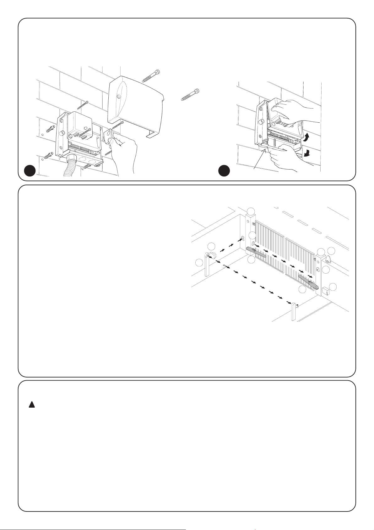
94
2.3) Instalacja typowa
Mając na celu wyjaśnienia niektórych aspektów systemu
automatyki drzwi i bram dwuskrzydłowych przedstawiamy
instalację typową.
Przypominamy, że:
• Wszystkie fotokomórki NICE posiadają system
SYNCHRONIZACJI, który służy do eliminacji problemu
interferencji pomiędzy parą fotokomórek (wyjaśnienia
umieszczone są w instrukcjach fotokomórek).
• Para fotokomórek FOTO podczas otwierania nie powoduje
żadnego efektu, ale odwraca ruch podczas zamykania.
• Para fotokomórek FOTO 1 blokuje ruch otwierania oraz
zamykania.
• Para fotokomórek FOTO 2 (połączona do wejścia AUX
odpowiednio zaprogramowanego) podczas zamykania nie
powoduje żadnego efektu, ale odwraca ruch podczas
otwierania.
2.2) Mocowanie centrali A400
Pojemnik posiada pokrywę, która zabezpiecza kartę elektroniczną
przed przypadkowym dotknięciem lub uszkodzeniem.
Tylko gdy jest to konieczne można dojść do karty elektronicznej
postępując tak jak wskazano na rys.1.
Aby ułatwić wykonanie otworów w części dolnej pojemnika można
odchylić podstawę, zgodnie z tym jak przedstawiono na rys. 1a,
oszczegół 1.
2.4) Połączenia elektryczne
Mając na uwadze bezpieczeństwo instalatora oraz aby
uniknąć uszkodzenia części centrali, podczas wykonywania
połączeń elektrycznych czy zakładania odbiornika radiowego
centrala musi być całkowicie odłąłczona od zasilania.
• Wejścia połączeń typu NC (zwykle zamknięte), gdy nie są
używane muszą zostać połączone w formie mostka ze
„WSPÓLNYM 24 V” (z wyjątkiem wejść fotokomórek
– wyjaśnienia w części związanej z funkcją FOTOTESTU).
• Gdy jakieś wejście posiada więcej połączeń NC, to muszą one
wszystkie być połączone szeregowo.
• Wejścia połączeń typu NA (zwykle otwarte), gdy nie są używane
muszą pozostać wolne.
• Gdy do tego samego wejścia należy więcej połączeń NA to
muszą one być połączone RÓWNOLEGLE.
• Połączenia muszą być typu mechanicznego i bez jakiegokolwiek
napięcia, nie dozwolone są połączenia typu określanego
jako: "PNP", "NPN", "Open Collector" itp.
• W siłownikach WINGO jest zamontowany kondensator
rozruchowy, niezbędny do funkcjonowania.
!
1 1a
FOTO 1
FOTO
FOTO 2
6
7
1
1
4
2
3
5
1.
Siłowniki elektromechaniczne.
2. Lampa sygnalizacyjna
3. Centrala „A400”
4. Selektor kluczowy
5. Para fotokomórek FOTO
6. Para fotokomórek FOTO1
7. Para fotokomórek FOTO2
szczegół 1
Page 95

95
PL
2.4.1) Schemat elektryczny
1
LN
M1 M2
2
5 6 7 8 9 101112 1314 151617181920212223
24 25
34
P1
ALT
DIODA OK
P2
PP
ZASILANIE
LAMPA
SYGNALIZACYJNA
ANTENA
OTWIERA
WSPÓLNY
ZAMYKA
OTWIERA
WSPÓLNY
ZAMYKA
WSPÓLNY 24V
24V
0
0
24V (NADAJNIK TX)
SCA 24Vpp
STOP (NC)
FOTO (NC)
FOTO 1 (NC)
KROK PO KROKU (NO)
AUX (NO)
FOTOTEST
24Vac
2.4.2) Opis połączeń
Przedstawiamy krótki opis możliwych rodzajów podłączeń do zacisków centrali.
Zaciski Funkcje Opis
1÷6 Zasilanie Zasilanie z sieci
4 Uziemienie Uziemienie silników
5÷6 Lampa sygnalizacyjna Podłączenie lampy sygnalizacyjnej (220V/max 40W)
7÷9 Silnik 1* Połączenie silnika M1 (skrzydło spodnie)
10÷12 Silnik 2* Połączenie silnika M2 (skrzydło wierzchnie)
13÷14 Fototest Zasilanie nadajników (TX) fotokomórek ( 24Vpp max 100mA)
15÷16 24 Vpp Zasilanie osprzętu, odbiorników (RX) fotokomórek, itp. (24Vpp max 150mA)
17 Wspólny 24 Vpp wspólny do wszystkich wejść / wyjść
18 SCA Lampa sygnalizacyjna otwartej bramy (24Vpp max 1.5W)
19 Stop Wejście NC (zwykle zamknięte) z funkcją STOP (alarm, blokada, bezpieczeństwa)
20 Foto
Wejście NC (zwykle zamknięte) urządzeń bezpieczeństwa (fotokomórki, brzegi pneumatyczne)
21 Foto 1
Wejście NC (zwykle zamknięte) urządzeń bezpieczeństwa (fotokomórki, brzegi pneumatyczne)
22 Krok po Kroku Wejście do sterowania cyklicznego (OTWIERA-STOP-ZAMYKA-STOP)
23 AUX ** Wejście dodatkowe
24÷25 Antena Wejście dla anteny odbiornika radiowego
* Dla 2 silników - pierwszy, który rusza podczas otwierania to silnik M2.
Centrala A400 automatycznie rozpoznaje czy jest zamontowany tylko jeden silnik, który musi być wtedy podłączony do wyjścia M2.
** Wejście dodatkowe AUX może być zaprogramowane dla jednej z poniższych funkcji (patrz rozdział 4 “Programowanie”):
Funkcja Typ wejścia Opis
OTWIERA CZE¸ ŚCIOWO typu
1 NO (zwykle otwarte) Częściowo otwiera skrzydło podłączone do silnika M2
OTWIERA CZE¸ ŚCIOWO typu
2 NO Otwiera oba skrzydła do połowy
OTWIERA NA Wykonuje tylko ruch otwierania
ZAMYKA NA Wykonuje tylko ruch zamykania
FOTO 2 NC (zwykle zamknięte) Funkcja FOTO 2
WYŁĄCZONY - - Brak funkcji
Gdy nie zostanie zaprogramowane inaczej to wejście AUX pełni funkcję OTWIERA CZEŚCIOWO typu 1.
UWAGA: Po__czenie fotokomórek z Fototestem (patrz rozdz. 2.4.4)
Uwaga: maszyna jest ju_ zaprogramowana i przystosowana do automatycznego odczytu czasu pracy (patrz rozdz. 2.5.1)
Page 96

96
Większość połączeń jest bardzo łatwa do wykonania, wiele z nich
to połączenia bezpośrednie do pojedynczego wyjścia funkcji lub
styku. Na poniższych rysunkach przedstawione są niektóre
przykłady połączeń urządzeń zewnętrznych.
2.4.3) Uwagi związane z podłączeniem
12345
12345
12345
12
12
12
LED OK
TX
FOTO
FOTO1
FOTO 2
RX
TX RX
TX RX
13
P1 P2 24 25
14 15 16 17 18 19 20 21 22 23
13
TX
FOTO
1 123452
LED OK
P1 P2 24 25
RX
14 15 16 17 18 19 20 21 22 23
Centrala A400 posiada zdolność wykonania Fototestu. Jest to
optymalne rozwiązanie dla układów bezpieczeństwa, i umieszcza
centralę A400 z jej zabezpieczeniami w grupie urządzeń ”2 kategorii”
według normy UNI EN 954-1 (wyd. 12/1998).
Przed każdym rozpoczęciem ruchu siłowników sprawdzane są
wszystkie urządzenia bezpieczeństwa i tylko, gdy test wynik jest
pozytywny ruch może być rozpoczęty.
Wszystko to jest możliwe tylko dzięki zastosowaniu specjalnej
konfiguracji w połączeniach urządzeń bezpieczeństwa; nadajniki
fotokomórek “TX” są zasilane oddzielnie względem odbiorników “RX”.
Pamiętajmy, że SYNCHRONIZACJA (dostępna we wszystkich
fotokomórkach NICE) jest jedynym sposobem gwarantującym brak
interferencji pomiędzy parą fotokomórek.
Wejścia poddane procedurze fototestu to FOTO, FOTO1 i wejście AUX,
gdy to wejście posiada konfigurację jako FOTO2. Faza fototestu odbywa się
na początku każdego ruchu i nie może być wyłączona, dlatego też gdy
którekolwiek z tych wejść nie jest używane należy podłączyć je do zacisku nr
13, patrz na następujące przykłady połączeń.
2.4.4) Fototest
Wolne miganie sygnalizuje fazę
otwierania.
Szybkie miganie sygnalizuje ruch
zamykania.
Światło stałe oznacza bramę
otwartą.
Schemat połączeń fotokomórek FOTO, FOTO1 i FOTO2.
Schemat połączeń tylko z jedną linią fotokomórek FOTO:
Przykład 1
Jak podłączyć selektor do
wykonania funkcji Krok po
kroku i Stop.
Przykład 2
Jak podłączyć selektor do
wykonania funkcji Krok po kroku
i jednej z przewidzianych na
wejściu dodatkowym
(PRZEJŚCIE DLA PIESZYCH,
TYLKO OTWIERA, TYLKO
ZAMYKA,...)
Przykład podłączenia radia
zewnętrznego z zasilaniem 24 Vpp.
1- kanał ➔ KROK PO KOKU
2- kanał ➔ AUX
Pod
łą
czenie Lampy sygnalizacyjnej C.A
Pod
łą
czenie zewnętrznego radia
Podłączenie selektora kluczowego
2 3
KROK PO
KROKU
KROK PO
KROKU
PASSO
PASSO
COM
ALT
COM
24V
17
18
24V
0V
2345612
1
15
16
22
17
23
1,5W
12
NA NC
17
22
19
17
PASSO
PASSO
COM COM
NA NA
17
22
23
17
AUX
Page 97

97
PL
Przykłady jednoprzewodowych połączeń fotokomórek
Podłączenie jednej linii fotokomórek FOTO
(odpowiednik rys.2)
Uwaga: wejście FOTO1 (21) nie jest używane, dlatego też musi
być podłączone do zacisku 13 tak aby funkcja FOTOTESTU była
przeprowadzona tylko dla pierwszej linii FOTO.
Połączenie FOTO i FOTO1
Uwaga: należy przestrzegać podłączeń do zasilania i uaktywnić
SYNCHRONIZACJE˛(dostępna we wszystkich fotokomórkach NICE).
Połączenie FOTO, FOTO1 i FOTO2
(odpowiednik rys.3)
Uwaga: należy przestrzegać podłączeń do zasilania i uaktywnć
SYNCHRONIZACJE˛(dostępna we wszystkich fotokomórkach NICE).
12345
12
TX
FOTO
RX
13
14
13
15
16
17
20
21
12345
12
12345
12
FOTO
FOTO 1
TX RX
TX RX
13
14
14
13
15
16
17
20
16
15
17
21
12345
12
12345
12
12345
12
FOTO
TX RX
FOTO 1
TX RX
FOTO 2
TX RX
13
14
14
13
14
13
15
16
17
20
16
15
17
21
16
15
17
23
2.4.5) Kontrola połączeń
Dalsze czynności będą związane z obwodami pod
napięciem. Niektóre z nich są pod napięciem sieci, dlatego też
są BARDZO NIEBEZPIECZNE! Czynności te należy
wykonywać bardzo ostrożnie i ZAWSZE NALEŻY PRACOWAĆ
W OBECNOŚCI DRUGIEJ OSOBY !
Po zakończeniu przewidzianych połączeń do automatyki należy
przeprowadzić kontrolę.
• Podłączyć napięcie do centrali, sprawdzić czy wszystkie Diody
świecą się przez kilka sekund z szybko migając.
• Sprawdzić czy do zacisków 1-2 dochodzi napięcie i czy w
zaciskach 15-16 obecne jest napięcie około 24 Vpp; gdy
wartości nie są odpowiednie wyłączyć prąd i dokładnie
sprawdzić połączenia i napięcie zasilania.
• Po początkowym przerywanym i szybkim świeceniu, Dioda OK
sygnalizuje bezbłędne funkcjonowanie centrali regularnym
miganiem z przerwą jednej sekundy. Gdy na wejściach
pojawi się jakiś sygnał sterujący, dioda OK mignie dwukrotnie,
sygnalizując rozpoznanie tego sygnału.
• Gdy połączenia są prawid[ówe, wejścia typu NC (Zwykle
zamknięte, to znaczy STOP, FOTO, FOTO1 będą miały Diodę
zaświeconą. Dioda Krok po Kroku i AUX nie będzie się świecić
(gdy FOTO2 i AUX są odpowiednio zaprogramowane to Dioda
AUX będzie zaświecona).
• Sprawdzić czy podczas naszej interwencji na urządzeniach
podłączonych do wejść zaświecą się i zgaszą odpowiednie
diody.
!
ALT Foto Foto1Krok
po Kroku
AUX
STOP PP
P1 P2
2.5) Poszukiwanie „zatrzymań mechanicznych”
Po zakończeniu kontroli można zacząć fazę automatycznego
poszukiwania „zatrzymań mechanicznych”. Faza ta jest konieczna
ponieważ centrala A400 musi obliczyć czas trwania ruchu
otwierania i zamykania.
Gdy centrala nie była nigdy zainstalowana, to znaczy, że w pamięci centrali nie ma
zachowanego czasu, wówczas procedura ta zostanie uaktywniona automatycznie.
Gdy jednak była już użytkowana to, aby ponownie ją uaktywnić należy najpierw
skasować całą pamięć (patrz rozdział „Programowanie - Kasowanie pamięci”). Aby
sprawdzić czy w pamięci są zachowane czasy, należy wyłączyć i następnie włączyć
zasilanie centrali. Gdy wszystkie diody świecą się z krótkimi przerwami przez 10
sekund to pamięć jest pusta; gdy świecą się tylko przez 3 sekundy to w pamięci
zachowane są czasy pracy silników.
Page 98

98
2.5.2) Poszukiwanie z wyłączoną funkcją amperometryczną
Gdy system odczytu amperometrycznego nie reaguje jak
powinien, można ustawić centralę do funkcjonowania na czas
całkowicie wyłączając funkcję amperometryczną (patrz rozdział
„Programowanie parametrów i funkcji – wyłączenie funkcji
amperometrycznej).
W tym przypadku instalator musi „poinformować” centralę o
dojściu do zatrzymania mechanicznego.
•
Przed rozpoczęciem poszukiwania z wyłączoną amperometryką
należy sprawdzić czy wszystkie urządzenia zabezpieczające dają
pozwolenie (aktywne: STOP, FOTO i FOTO1).
• Skrzydła mogą znajdować się w jakiejkolwiek pozycji, wskazane
jest aby znajdoway się w połowie biegu.
•
Przycisnąć przycisk PP (Krok po kroku), który jest
przyciskiem startowym fazy poszukiwania. Przebieg jej to:
- Krótkie otwarcie, najpierw M2 później M1.
Gdy silniki nie startują podczas otwierania lub pierwszy, który
startuje to nie M2, należy zablokować poszukiwanie poprzez
przyciśnięcie przycisku STOP i sprawdzić połączenia silników.
- Zamknięcie silnika M1, aż do momentu zatrzymania
mechanicznego podczas zamykania.
• Gdy M1 dojdzie do zatrzymania mechanicznego podczas
zamykania, przycisnąć PP (Krok po kroku).
- Zamknięcie silnika M2, aż do momentu zatrzymania
mechanicznego podczas zamykania.
• Gdy M2 osiągnie zatrzymanie mechaniczne podczas
zamykania, przycisnąć PP.
- Po jakiejś chwili zacznie się ruch otwierania silnika M2.
• Gdy M2 osiągnie zatrzymanie mechaniczne podczas
otwierania, przycisnąć PP.
- Po jakiejś chwili zacznie się ruch otwierania silnika M1.
• Gdy M1 osiągnie zatrzymanie mechaniczne podczas
otwierania, przycisnąć PP.
- Po jakiejś chwili zacznie się pełen ruch zamykania.
Silniki rozpoczną pracę z przesunięciem czasowym a celem jest
dojście do cłkowitego zamknięcia utrzymując przestawienie fazy
takie, aby uniknąć niebezpiecznego zamknięcia nożycowego
skrzydeł.
- Koniec procedury z zachowaniem wszystkich mierzonych
czasów.
Te wszystkie fazy muszą być wykonane w kolejności jedna za
drugą, instalator ma zainterweniować, poprzez przyciśnięcie PP
tylko w odpowiednim momencie. Gdy ta procedura nie postępuje
w sposób poprawny należy przerwać ją przyciskając przycisk
STOP. Uaktywnienie zabezpieczenia lub wprowadzenie
jakiegokolwiek polecenia powoduje natychmiastowe przerwanie
procedury.
2.5.1) Poszukiwanie automatyczne
Procedura ta jest całkowicie automatyczna i opiera się na
pomiarze obciążenia silników w momencie „zatrzymania
mechanicznego” podczas otwierania i zamykania.
W automatyce „szczególnie trudnej” może zdarzyć się, że system odczytu
zmian prądu silników nie reaguje należycie, należy wtedy zmienić poziom czułości
„amperometrycznej” lub ewentualnie zastosować programowanie ręczne, patrz
rozdział „Poszukiwanie z wyłączoną amperometryczną".
• Przed rozpoczęciem poszukiwania automatycznego należy
sprawdzić czy wszystkie urządzenia bezpieczeństwa dają
pozwolenie na ruch (STOP, FOTO i aktywna FOTO1).
Uaktywnienie jednego z zabezpieczeń lub otrzymanie jakiegoś polecenia
podczas tej procedury powoduje natychmiastowe jej przerwanie.
• Skrzydła mogą znajdować się w jakiejkolwiek pozycji, wskazane
jest aby znajdowały się w połowie biegu.
• Przycisnąć przycisk PP (Krok po kroku), rozpoczyna on fazę
poszukiwania, przebiegającą następująco:
- Krótkie otwarcie, najpierw M2 i później M1.
Gdy silniki nie startują podczas otwierania lub pierwszy, który
porusza się nie jest M2, należy zablokować poszukiwanie
przyciskiem STOP (ALT) i sprawdzić połączenia silników.
- Zamknięcie silnika M1 aż do zatrzymania mechanicznego
podczas zamykania.
- Zamknięcie silnika M2 aż do zatrzymania mechanicznego
podczas zamykania.
- Rozpoczęcie otwierania silnika M2.
- Po przewidzianym przesunięciu fazowym rozpoczęcie otwarcia
silnika M1.
Gdy przesunięcie fazowe nie jest wystarczające, należy
natychmiast zablokować poszukiwanie poprzez przyciśnięcie
przycisku STOP, i należy zmienić czas (patrz rozdział
„Programowanie”).
- Pomiar czasu niezbędny, aby silniki doszły do zatrzymania
mechanicznego podczas otwierania.
- Pełen ruch zamykania.
Silniki rozpoczną pracę z przesunięciem czasowym a celem jest
dojście do całkowitego zamknięcia, utrzymując przestawienie
fazy takie, aby uniknąć niebezpiecznego zamknięcia
nożycowego skrzydeł.
- Zakończenie procedury z zachowaniem wszystkich obliczonych
czasów.
Wszystkie te fazy muszą odbyć się jedna po drugiej bez ingerencji
operatora. Gdy tak nie będzie, to taka procedura nie zostanie
prawidłowo wykonana i należy ją przermać poprzez przyciśnięcie
przycisku STOP. Sprawdzić połączenia i powtórzyć procedurę
modyfikując ewentualnie nawet granice interwencji
amperometrycznej (patrz rozdział „Programowanie”).
ALT PP
P1 P2
ALT PP
P1 P2
Page 99

99
PL
W centrali A400 możemy programować wiele funkcji i parametrów
aby dostosować urządzenie do wymagań użytkownika i podnieść
jego bezpieczeństwo w każdych warunkach zastosowania.
Funkcjonowanie „Automatyczne”
Funkcja ta przewiduje zamykanie automatyczne po
zaprogramowanym czasie przerwy, na początku czas przerwy
ustawiony jest na 20 sekund, ale może zostać zmieniony na 5, 10,
20, 40, 80 sekund.
Funkcjonowanie w „Zespołach mieszkaniowych”
Funkcja ta jest niezbędna, gdy dużo osób steruje automatem pilotami
radiowymi. Gdy ta funkcja jest uaktywniona, to każdy wyśany impuls
powoduje otwarcie, które nie może być przerwane przez inne impulsy z
wyjątkiem alarmowych / bezpieczeństwa (STOP, FOTO1, FOTO2) i
natychmiastowe zamknięcie (AUX ustawiona jako „Tylko zamyka”).
Wcześniejsze zaświecenie lampy sygnalizacyjnej
Funkcja ta włącza lampę sygnalizacyjna przed rozpoczęciem ruchu,
czas ten może być ustawiony na 2,4,6,8,10 sekund.
Zamknij po 4 sekundach po foto:
Wraz z zamykaniem automatycznym funkcja ta pozwala na
skrócenie zwłoki przed zamknięciem na 4 sekundy po zwolnieniu
fotokomórki FOTO. Oznacza ta, że brama zamknie się po 4
sekundach po przejściu użytkownika.
Przesuwanie fazy skrzydeł:
Funkcja ta powoduje w otwieraniu opóźnienie uaktywnienia
silnika M1 w stosunku do silnika M2 aby uniknąć ich
niebezpiecznego zablokowania się. Przesunięcie fazowe podczas
zamykania jest już zaprogramowane (wymagane w normach
bezpieczeństwa) i obliczane jest automatycznie w centrali tak aby
uzyskać to samo przesunięcie fazowe podczas otwierania.
Czułość amperometryczna:
Centrala posiada system do mierzenia absorbowanego,
przez oba silniki, prądu, co służy do odczytu „zatrzymań
mechanicznych” i ewentualnych przeszkód podczas ruchu bramy.
Jako, że absorbowany prąd zależy od wielu warunków (waga
bramy, różne tarcia, uderzenia wiatru, zmiany napięcia, itp. )
przewidziana została możliwość zmiany granicy interwencji.
Zostało przewidziane pięć poziomów: poziom 1 – najbardziej
czuły, poziom 5 – mniej czuły. Centrala ustawiona jest na poziomie
2, jest to poziom optymalny dla większości przypadków.
Wejście dodatkowe AUX:
Centrala posiada dodatkowe wejście, które może pęnić poniższe
funkcje:
• Otwieranie częściowe typu 1: pełni taką samą funkcję jak
wejście Krok po kroku powodując jednak uruchomienie tylko
silnika M2. Funkcja otwarcia częściowego jest aktywna tylko przy
bramie całkowicie zamkniętej, inaczej będzie zrozumiana jakby to
była funkcja Skok po skoku.
• Otwieranie częściowe typu 2: wykonuje taką samą funkcję jak
wejście Krok po kroku powodując otwieranie dwóch skrzydeł
tylko do połowy czasu przewidzianego na całkowite otwarcie.
Działa tylko przy bramie całkowitej zamkniętej, w innym
przypadku zostanie zrozumiane jakby to by[a zwyk[a funkcja
Krok po kroku.
• Tylko otwiera: to wejście wykonuje tylko otwieranie z sekwencją
Otwiera-Stop-Otwiera-Stop.
• Tylko zamyka: to wejście wykonuje tylko zamykanie z sekwencją
Zamyka-Stop-Zamyka-Stop.
• Foto 2: pełni funkcję wejścia trzeciej linii fotokomórek - FOTO 2.
• Wyłączony: wejście nie ma żadnej funkcji.
Podstawą funkcjonowania amperometrycznego są zmiany
absorbowanego przez silniki prądu. Gdy na początku ruchu
silnik jest zablokowany, ponieważ skrzydło już znajduje się w
fazie zatrzymania mechanicznego, nie będzie żadnej zmiany
prądu i z tego powodu przeszkoda nie zostanie odczytana.
Funkcja „amperometryczna” odpowiednio uregulowana
(wraz z innymi niezbędnymi zmianami) może być niezbędna do
dostosowania się do norm europejskich, EN 12453 i EN 12445,
które wymagają zastosowania technik lub urządzeń do
ograniczenia sił i niebezpieczeństwa podczas ruchu drzwi i
bram automatycznych.
Gdy warunki będą tego wymagały to można wyłączyć funkcję
amperometryczną i doprowadzić do funkcjonowania centrali na
czas; w tym też celu zapoznać się z punktem „Poszukiwanie z
wyłączoną funkcją amperometryczną”.
Gdy funkcja amperometryczna zostanie wyłączona to
silniki będą pracowąy „pełną mocą” przez cały czas ruchu.
Należy wykonać uważną analizę ryzyka i zastosować inne
ewentualne urządzenia bezpieczeństwa aby osiągnąć poziom
bezpieczeństwa wymagany normami.
!!!
3) Funkcje z możliwością programowania:
3.1) Funkcje wstępnie zaprogramowane.
Po fazie poszukiwania Centrala A400 oferuje wiele funkcji z możliwością ich
programowania (patrz rozdział „Funkcje z możliwością programowania”).
Funkcje te są wstępnie fabrycznie ustawione według typowej konfiguracji,
która zaspakaja wymagania większości użytkowników.
•
Zamykanie automatyczne : po 20 sekundach
•
Przesuwanie fazy : 4 sekundy
•
Wcześniejsze zaświecenie : nie aktywna
lampy sygnalizacyjnej
•
Wejście dodatkowe : otwieranie częściowe typu 1
(uaktywnia tylko silnik M2)
•
Czułość amperometryczna : Stopień 2.
Funkcje mogą być zmienione w każdej chwili, przed i po fazie
poszukiwania, odpowiednią procedurą programowania.
Page 100

100
4.2) Sposoby programowania
Do wszystkich faz programowania używa się tylko dwóch
przycisków: P1 i P2, znajdujących się na płycie oraz 5 Diod
„WEJŚĆ”, które zwykle wskazują stan wejść. W tym przypadku
sygnalizują one „Parametr” zaznaczony.
Przykład:
Przewidziane zostały także 2 poziomy programowania:
• Na pierwszym poziomie można uaktywnić i wyłączyć funkcje.
Każda Dioda Wejścia odpowiada danej funkcji, gdy Dioda
świeci się to funkcja jej odpowiadająca jest uaktywniona, gdy
nie świeci się to funkcja nie jest aktywna.
Dioda 1: Funkcja „Automatyczna”
Dioda 2: Funkcja „Zespołu mieszkalnego”
Dioda 3: Wcześniejsze zaświecenie się lampy sygnalizacyjnej
Dioda 4: Zamknij po foto (po zwolnieniu linii)
Dioda 5: Opóźnienie podczas otwierania
•
Od pierwszego poziomu można przejść do drugiego poziomu, w
którym można ustawić parametr określający daną funkcję. Każdej
Diodzie odpowiada inna wartość ustawianego parametru.
4.1) Kasowanie pamięci
Każda zmiana parametru zastępuje poprzednie ustawienie,
dlatego zwykle nie jest konieczne kasowanie całej pamięci.
Każde całkowite kasowanie pamięci jest możliwe tylko według
poniższego prostego sposobu:
Po skasowaniu pamięci należy wykonać nowe
„poszukiwanie zatrzymań mechanicznych”, a pozostałe
funkcje powrócał do podstawowych wartosłci fabrycznych.
!
Pierwszy poziom:
Dioda 1 Dioda 2 Dioda 3 Dioda 4 Dioda 5
Funkcja Funkcja
Wcześniejsze zaświecenie
Zamknij 4 sekundy Opóźnienie podczas
„Automatyczna”
„Zespołu mieszkalnego”
się lampy sygnalizacyjnej
po foto (po odczycie) otwierania
Drugi poziom:
Parametr: Parametr: Parametr: Parametr: Parametr:
Czas Przerwy Wejście AUX Czas wcześniejszego
Czułość amperometryczna
Czas opóźnienia
zaświecenia się
lampy sygnalizacyjnej
Dioda 1 : 5s
Dioda 1 : Otwiera częściowo typ 1
Dioda 1 : 2s Dioda 1 : Stopień 1s Dioda 1 : 2s
Dioda 2 : 10s
Dioda 2 : Otwiera częściowo typ 2
Dioda 2 : 4s Dioda 2 : Stopień 2s Dioda 2 : 4s
Dioda 3 : 20s Dioda 3 : Tylko otwiera Dioda 3 : 6s Dioda 3 : Stopień 3s Dioda 3 : 6s
Dioda 4 : 40s Dioda 4 : Tylko zamyka Dioda 4 : 8s Dioda 4 : Stopień 4s Dioda 4 : 8s
Dioda 5 : 80s Dioda 5 : Foto 2 Dioda 5 : 10s Dioda 5 : Stopień 5s Dioda 5 : 10s
Diody nie świecą się: Diody nie świecą się:
wejście wyłączone.
Amperometryczna wyłączona
Stopień 1 = najbardziej czuły
Stopień 5 = najmniej czuły
Wszystkie funkcje opisane w rozdziale “Funkcje z możliwością
programowania” mogą być wybrane w fazie programowania, która
kończy się zachowaniem w pamięci dokonanego wyboru.
W centrali znajduje się pamięć, która zachowuje funkcje i
parametry związane z automatyką.
4) Programowanie:
3s
Tabela „A1” Aby skasować pamięć: Przykład
1. Wyłączyć napięcie od centrali
2. Przycisnąć i trzymać wciśnięte przyciski P1 i P2 na płycie centrali.
3. Podłączyć napięcie do centrali
4. Odczekać, min. 3 sekundy, po czym zwolnić przyciski.
Uwaga: gdy kasowanie pamięci zostało wykonane poprawnie to wszystkie Diody zgasną na 1 sekundę.
12345
P1 P2
P2P1
P2P1
W tym przypadku jest
uaktywniona Funkcja
„Automatyczna”,
wcześniejsze zaświecenie
się lampy sygnalizacyjnej
i opóźnienie otwierania
silnika M1.
 Loading...