

Nexo Geo M6, Geo M6Bass User Manual
GEO M6 Series
Geo M620 & Geo M6Bass Tangent Array Modules
User Manual
GEO M6 Series User Manual V1.01
Date: 2014/07/21

Page 2/62 PLEASE READ CAREFULLY BEFORE PROCEEDING
GEO Technology is radically new thinking
The GEO R&D Project has, to date, resulted in the following patent applications:
The GEO Hyperboloid Reflective Wavesource™ differs radically from the megaphone-variant type
horns you know and love (or hate). “Tried and true” methods will produce entirely unexpected results.
HRW technology produces precise and predictable results.
The Configurable Directivity Flange. A waveguide that allows the operator to alter its behaviour. An
unprecedented NEXO development that is easy to use – once you know how and when.
The Directivity Phase Device needs no operator input to function, but it is reassuring to know that the
coupling of the midrange of the system is considered as important as the high frequencies…
DSP-driven Directional Sub-bass devices are a new approach to controlling LF/VLF acoustic energy.
GEO is not hard to use when you understand how…
The technology behind GEO is revolutionary, but it is grounded in years of practical experience with the
problems of delivering high quality professional sound to large audiences at high SPL levels. The GEO
toolbox includes NS-1 - a simple yet powerful and highly predictive design tool. The array assembly
system is keyed to the design software and will easily enable you to deploy your design with great
precision. The NXAMP Amplified Digital TDcontroller provides driver protection and system optimization
as well as DSP-driven cardioid pattern control for the LS and RS series Subwoofers.
GEO is a high precision system
The GEO HRW™ controls acoustic energy more precisely than other multiple element waveguides. It
also makes GEO less forgiving of mistakes. Whilst conventional horns never combine into a coherent
array, they may deliver acceptable results even if the design and deployment of the system is less than
optimal. This is not the case with GEO where careless installation produces catastrophic results.
A GEO Tangent Array is not a “line array”
GEO Technology is equally effective in designing and deploying tangent horizontal arrays or curved
vertical arrays. For best results in a specific application the user needs to know how multi-speaker
arrays interact with audience geometry, along with the benefits and drawbacks of curved vertical arrays
and horizontal arrays.
Curved tangent arrays require different design techniques
For the past 20 years, sound reinforcement professionals have worked with horizontal arrays that use
conventional horns to deliver [more or less] ‘equal power to equal angles’. Curved vertical arrays are
designed to deliver [more or less] equal power to equal areas’. When arrays use conventional horns,
the lack of precision, overlap and interference masks errors in array design and aiming. The highly
precise GEO wavesource responds accurately, consistently and predictably to the design and
deployment of a curved vertical tangent array. This is why the GEO rigging system is designed to
control angular splay to 0.01° precision.
GEO curved tangent arrays require different operational techniques
Over the years, system designers and operators have developed a number of signal processing
techniques to disguise and partly overcome the limitations of horn design. “Frequency shading,”
“amplitude shading,” “system tuning,” all of these are tools of the advanced sound system operator.
NONE OF THESE TECHNIQUES ARE APPLICABLE TO GEO TANGENT ARRAYS. Instead of
enhancing the array’s performance they will severely degrade it.
Take time to learn how to get great results with GEO Technology. It is an investment that will pay off in
more satisfied clients, more efficient operating procedures and more recognition for your skill as a
sound system designer and operator. A comprehensive understanding of GEO theory, tangent arrays,
and specific features of the GEO M6 Series will help you to operate your system at its full potential.
PLEASE READ CAREFULLY BEFORE PROCEEDING Page 3/62
PLEASE READ CAREFULLY BEFORE PROCEEDING
BASIC PRECAUTIONS
Do not open the speaker system or attempt to disassemble the internal parts or modify them in any
way. The speaker system contains no user-serviceable parts. If it should appear to be malfunctioning or
damaged, discontinue use immediately and have it inspected by qualified NEXO service personnel.
Water exposure: Do not expose the speaker system to direct rain, do not use it near water or in wet
conditions. Do not place containers with liquid on speaker system as they might spill into openings. If
any liquid such as water seeps into the speaker system, have it inspected by qualified NEXO personnel.
SYSTEM DEPLOYMENT SAFETY RULES
Read User Manual before deployment. Before use of enclosed speaker system,
please ensure that anyone involved in system deployment understands the rigging –
stacking – pole mounting safety rules as described in the speaker system User Manual.
Failure to do this exposes people to potential injury or death.
Always consult qualified NEXO personnel if the device installation requires construction work and make
sure to observe the following precautions:
Mounting precautions
- choose mounting hardware and an installation location that can support the weight of the speaker
system;
- do not use speaker system handles for suspended installation;
- do not expose speaker system to excessive dust or vibration, or extreme cold or heat to prevent
possibility of component damage;
- do not place the speaker system in an unstable position from which it might fall accidentally;
- if speaker systems uses a stand, ensure that stand specifications are adapted, and that stand
height does not exceed 1.40m/55”; never move the stand while the speaker is in position.
Connection and powering precautions
- remove all connected cables before moving the speaker system;
- turn off AC power of all power amplifier units before connecting the speaker system;
- when turning on the AC power to the audio system, always turn on the power amplifier last; when
turning the AC power off, always turn off the power amplifier first;
- when used in cold conditions, a gradual power ramp up should applied to the system on an 5 mn
period to allow the loudspeaker components to stabilize during the very first minutes of usage.
Inspect the speaker system periodically.
Page 4/62 PLEASE READ CAREFULLY BEFORE PROCEEDING
SAFETY INSTRUCTIONS FOR NEXO TD CONTROLLERS
NEXO ANALOGUE PSTDCONTROLLERS, NX242 DIGITAL CONTROLLER,
NXAMP4x1 AND NXAMP4x4 POWERED CONTROLLERS ARE CLASS 1
APPARATUS AND MUST BE EARTHED.
THE GREEN AND YELLOW WIRE OF THE MAINS CORD MUST ALWAYS BE CONNECTED TO AN
INSTALLATION SAFETY EARTH OR GROUND. THE EARTH IS ESSENTIAL FOR PERSONAL
SAFETY AS WELL AS THE CORRECT OPERATION OF THE SYSTEM, AND IS INTERNALLY
CONNECTED TO ALL EXPOSED METAL SURFACES.
- Read these instructions.
- Keep these instructions.
- Heed all warnings.
- Follow all instructions.
- Do not use this apparatus near water.
- Clean only with dry cloth.
- Do not block any ventilation openings. Install in accordance with the manufacturer’s instructions.
- Do not install near any heat sources such as radiators, heat registers, stoves, or other apparatus
(including amplifiers) that produce heat.
- Do not defeat the safety purpose of the polarized or grounding-type plug. A polarized plug has two
blades with one wider than the other. A grounding type plug has two blades and a third grounding
prong. The wide blade or the third prong are provided for your safety. If the provided plug does not
fit into your outlet, consult an electrician for replacement of the obsolete outlet. (US market)
- Protect the power cord from being walked on or pinched particularly at plugs, convenience
receptacles, and the point where they exit from the apparatus.
- Only use attachments/accessories specified by the manufacturer.
- Unplug this apparatus during lightning storms or when unused for long periods of time.
- Refer all servicing to qualified service personnel. Servicing is required when the apparatus has
been damaged in any way, such as power-supply cord or plug is damaged, liquid has been spilled
or objects have fallen into the apparatus, the apparatus has been exposed to rain or moisture, does
not operate normally, or has been dropped.
PLEASE READ CAREFULLY BEFORE PROCEEDING Page 5/62
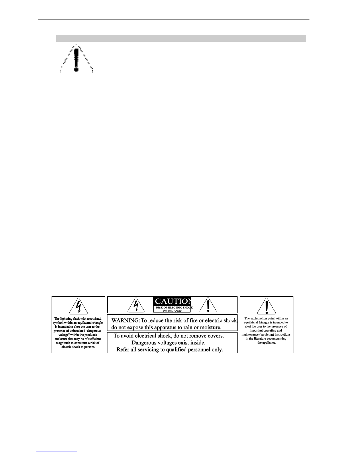
HIGH SOUND PRESSURE LEVELS
Exposure to extremely high noise levels may cause permanent hearing loss.
Individuals vary considerably in susceptibility to noise-induced hearing loss but nearly
everyone will lose some hearing if exposed to sufficiently intense noise for a sufficient
period of time. The U.S. Government’s Occupational and Health Administration (OSHA)
has specified the following permissible noise level exposures: Sound Duration Per
Day In Hours
Sound Level dBA, Slow Response
8
90 6 92
4
95 3 97 2 100
1 ½
102 1 105
½
110
¼ or less
115
According to OSHA, any exposure in excess of the above permissible limits could result in some
hearing loss. Ear plugs or protectors to the ear canals or over the ears must be worn when operating
this amplification system in order to prevent permanent hearing loss, if exposure is in excess of the
limits as set forth above. To ensure against potentially dangerous exposure to high sound pressure
levels, it is recommended that all persons exposed to equipment capable of producing high sound
pressure levels such as this amplification system be protected by hearing protectors while this unit is in
operation.
DISPOSAL OF OLD ELECTRICAL & ELECTRONIC EQUIPMENT
This symbol on the product or on its packaging indicates that it shall not be treated
as household waste. Instead it shall be handed over to the applicable collection
point for the recycling of electrical and electronic equipment. By ensuring this
product is disposed of correctly, you will help prevent potential negative
consequence for the environment and human health, which could otherwise be
caused by inappropriate waste handling of this product. The recycling of materials
will help to conserve natural resources. For more detailed information about
recycling of this product, please contact your local city office, your household waste
disposal service or the shop where you purchased the product.

Page 6/62 CONTENTS
CONTENTS
PLEASE READ CAREFULLY BEFORE PROCEEDING .................................................................... 3
CONTENTS......................................................................................................................................... 6
1 INTRODUCTION ......................................................................................................................... 8
2 GEO M6 GENERAL SET-UP INSTRUCTIONS ........................................................................... 9
2.1 SPEAKER CONNECTION .......................................................................................................... 9
GEO M620 connectors ..................................................................................................... 9 2.1.1
GEO M6Bass connectors ................................................................................................. 9 2.1.2
Cabling ............................................................................................................................. 9 2.1.3
3 AMPLIFIER SELECTION FOR USE WITH GEO M6 & LS18 .................................................... 10
3.1 GEO M6 AND NXAMP TDCONTROLLERS ............................................................................. 10
NXAMP connectors ........................................................................................................ 10 3.1.1
GEO M6 and NXAMP4x1 recommended loading ........................................................... 10 3.1.2
4 GEO M6 SETUPS ON NEXO TD CONTROLLERS ................................................................... 11
4.1 NXAMP TDCONTROLLERS .................................................................................................. 11
5 CONNECTION DIAGRAMS ...................................................................................................... 12
5.1 6 X GEO M620 STEREO – 2 X LS18 MONO ON NXAMP4X1 ................................................... 12
5.2 12 X GEO M620 ON NXAMP4X1 ......................................................................................... 13
5.3 3 X GEO M620 STEREO – 3 X GEO M6B STEREO - 2 X LS18 MONO ON NXAMP4X1 ............... 14
5.4 6 X GEO M620 STEREO – 6X GEO M6B STEREO ON NXAMP4X1 .......................................... 15
6 NS-1 SIMULATION SOFTWARE .............................................................................................. 16
7 CONFIGURABLE DIRECTIVITY DEVICE ................................................................................. 17
7.1 INSTALLING & REMOVING GEO’S CONFIGURABLE DIRECTIVITY FLANGES ................................. 17
7.2 WHEN & WHERE TO USE CONFIGURABLE DIRECTIVITY FLANGES ............................................. 18
8 GEO M6 HARDWARE SETUP PROCEDURE .......................................................................... 19
8.1 SAFETY FIRST .................................................................................................................. 19
Flown Systems Safety .................................................................................................... 19 8.1.1
Ground Stacking Safety ................................................................................................. 20 8.1.2
Contacts ......................................................................................................................... 21 8.1.3
8.2 GENERAL DESCRIPTION ....................................................................................................... 22
GEO M6 modules rigging system ................................................................................... 22 8.2.1
GEO M6 “Left” and “Right” configuration ........................................................................ 22 8.2.2
GEO M6 Angle Setting Bar configuration ....................................................................... 23 8.2.3
Accessories and kits....................................................................................................... 24 8.2.4
Described configurations ................................................................................................ 25 8.2.5
WARNINGS ON GEO M6 ACCESSORIES .................................................................... 26 8.2.6
8.3 INSTALLING GEO M6 ........................................................................................................... 26
1 to 3 (maximum) GEO M6 wall mounted ....................................................................... 27 8.3.1
1 to 3 (maximum) Geo M6 ceiling mounted .................................................................... 28 8.3.2
4 to 12 (maximum) GEO M6 ceiling mounted ................................................................. 29
8.3.3
1 to 3 (maximum) GEO M6 pole mounted ...................................................................... 30 8.3.4
1 to 3 GEO (maximum) M6 truss or cable mounted ........................................................ 32 8.3.5
1 to 6 (maximum) GEO M6 stacked on Sub ................................................................... 33 8.3.6
4 to 12 (maximum) GEO M6 flown ................................................................................. 34 8.3.7
8.4 TESTING AND MAINTENANCE OF THE SYSTEM ........................................................................ 37

CONTENTS Page 7/62
9 SYSTEM ALIGNMENT GUIDELINES ........................................................................................ 38
9.1 GEO M6 VERTICAL CLUSTER DESIGN ................................................................................... 38
9.2 STACKED LS18S AND FLOWN GEO M6 ................................................................................. 38
9.3 DRIVING THE LS18S FROM THE AUX SEND ............................................................................ 39
9.4 RECOMMENDED INSTALLATION TOOLS AND EQUIPMENT .......................................................... 39
10 GEO M6 – LS18S SYSTEM CHECK LIST ................................................................................. 41
10.1 ARE THE SPEAKERS PROPERLY CONNECTED AND ANGLED ? .................................................... 41
10.2 FINAL PRE-SOUND CHECK CHECK ........................................................................................ 41
11 TECHNICAL SPECIFICATIONS ................................................................................................ 42
11.1 LS18 SUBWOOFER............................................................................................................... 42
System specifications ................................................................................................. 42 11.1.1
Dimensions ................................................................................................................. 43 11.1.2
11.2 GEO M620 MODULE ............................................................................................................ 44
System specifications ................................................................................................. 44 11.2.1
Dimensions ................................................................................................................. 45 11.2.2
11.3 GEO M6BASS MODULE ........................................................................................................ 46
System specifications ................................................................................................. 46 11.3.1
Dimensions ................................................................................................................. 47 11.3.2
11.4 GEO M6 ACCESSORIES ....................................................................................................... 48
GMT-BUMPER ........................................................................................................... 48 11.4.1
GMT-EXBAR .............................................................................................................. 49 11.4.2
GMT-BPDAPT ............................................................................................................ 50 11.4.3
GMT-LBUMPER ......................................................................................................... 51 11.4.4
GMT-LBPADPT .......................................................................................................... 52 11.4.5
VNT-POLE .................................................................................................................. 53 11.4.1
VNT-XHBRK ............................................................................................................... 54 11.4.2
VNT-TCBRK ................................................................................................ ............... 55 11.4.3
GMT-IPCOV ............................................................................................................... 56 11.4.1
VXT-BL515 PUSH PINS ............................................................................................. 57 11.4.2
GMT-BNFIX ................................................................................................................ 57 11.4.3
VNI-WS15 ................................................................................................................... 58 11.4.4
GMT-6CASE ............................................................................................................... 59 11.4.5
12 GEO M6 SERIES PARTS & ACCESSORIES LIST ................................................................... 60
12.1 MODULES & CONTROL ELECTRONICS LIST ............................................................................. 60
12.2 ACCESSORIES LIST .............................................................................................................. 60
13 USER NOTES ............................................................................................................................ 62
Page 8/62 INTRODUCTION
1 INTRODUCTION
Thank you for selecting a NEXO GEO M6 Series Tangent Array System.
This manual is intended to provide you with necessary and useful information about your GEO M6
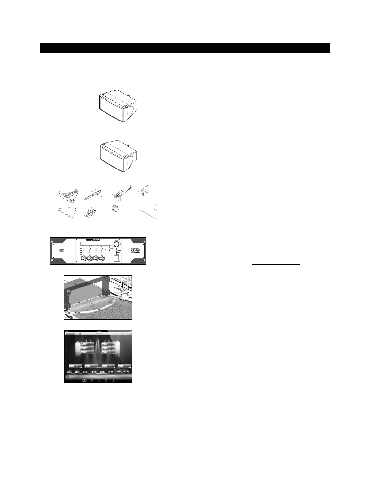
System, which includes the following products:
GEO M620 is a 20° Tangent Array Module. It
comprises 1x6.5” (17cm) 8 ohms LF/MF driver and
1x1.5” voice coil, 1” Throat 16 Ohm HF Driver loaded
by a 15° Hyperboloid Reflective Wavesource™.
GEO M6B is a Bass-Mid Reinforcement module for
Geo M620. It comprises 1x6.5” (17cm) 8 ohms LF/MF
driver ™.
GEO M6 Accessory Range. a full range of
accessories that provides safe, flexible and simple
means of installing Geo M6 as single or multiple units
in fixed installation as well as in touring applications.
GEO M6 modules are controlled, powered and
monitored by NXAMP4x1.For a complete description
of this controller, please refer to User Manual.
NXAMP DSP algorithms and parameters are fixed in
software and updated regularly: Please consult the
NEXO web site (www.nexo-sa.com) for the latest
software releases.
NS-1 simulation software assists in the design and
implementation of vertical tangent GEO arrays.
Please consult the NEXO web site (www.nexosa.com) for the latest software releases.
Available for iPad and iPhone, NEXO NeMo provides
remote control over an NXAMP network from
anywhere in the venue, thanks to an intuitive and
graphically attractive user interface. NeMo is available
on iTunes.
Please devote your time and attention to reading this manual. A comprehensive understanding of GEO
theory, tangent arrays and specific features of GEO M6 will help you to operate your system at its full
potential.
GEO M6 GENERAL SET-UP INSTRUCTIONS Page 9/62
2 GEO M6 GENERAL SET-UP INSTRUCTIONS
2.1 Speaker connection
GEO M620 and M6B are connected with Speakon NL4FC plugs (not supplied). The 4 pins of the 2
Speakon sockets identified in / out are connected in parallel within the enclosure.
Either connector can be used to connect to NXAMP or to link to an additional Geo M6 cabinet.
Therefore, a single 4-conductor cable can connect two NXAMP channels to various Geo M620 and
M6B.
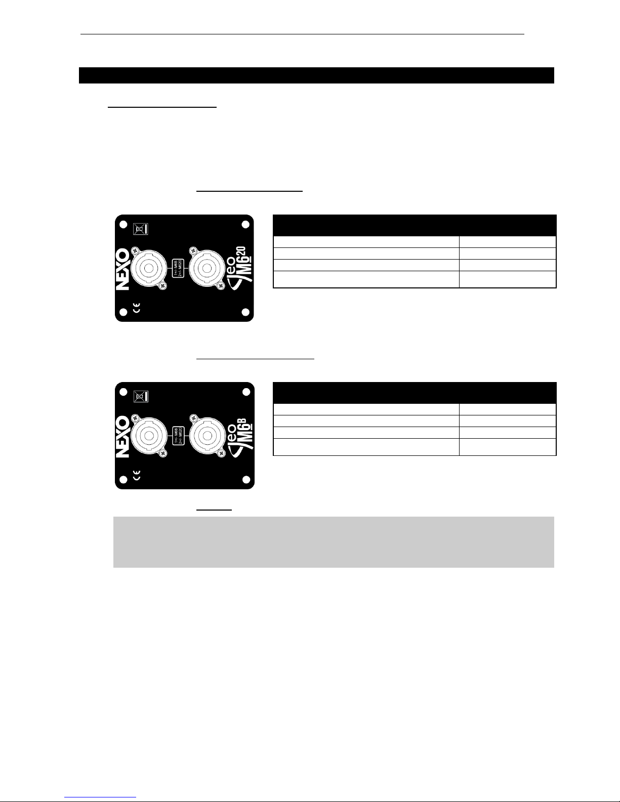
GEO M620 connectors 2.1.1
Connectors are wired as follows:
GEO M6Bass connectors 2.1.2
Connectors are wired as follows:
Cabling 2.1.3
IMPORTANT
Long speaker cables induce capacitive effects – up to hundreds of pF depending on the
quality of the cable - with a low-pass effect on high frequencies. If long speaker cables
must be used, ensure that they do not remain coiled while in use.
Speakon Connector
M620
1(-)
Through
1(+)
Through
2(-)
Geo M620 (-)
2(+)
Geo M620 (+)
Speakon Connector
M620
1(-)
Geo M6Bass (-)
1(+)
Geo M6Bass (+)
2(-)
Through
2(+)
Through
Page 10/62 AMPLIFIER SELECTION FOR USE WITH GEO M6 & LS18
3 AMPLIFIER SELECTION FOR USE WITH GEO M6 & LS18
3.1 GEO M6 and NXAMP TDControllers
NEXO Powered TDControllers NXAMP 4X1 is an integrated solution for Control and amplification for all
NEXO speaker ranges.
NXAMP4x1 power capability is listed in the table below:
Mode
4 Channels
Bridge Stereo
NXAMP4x1
4 x 600 Watts / 8 Ohms
4 x 900 Watts / 4 Ohms
4 x 1300 Watts / 2 Ohms
2 x 1800 Watts / 8 Ohms
2 x 2600 Watts / 4 Ohms
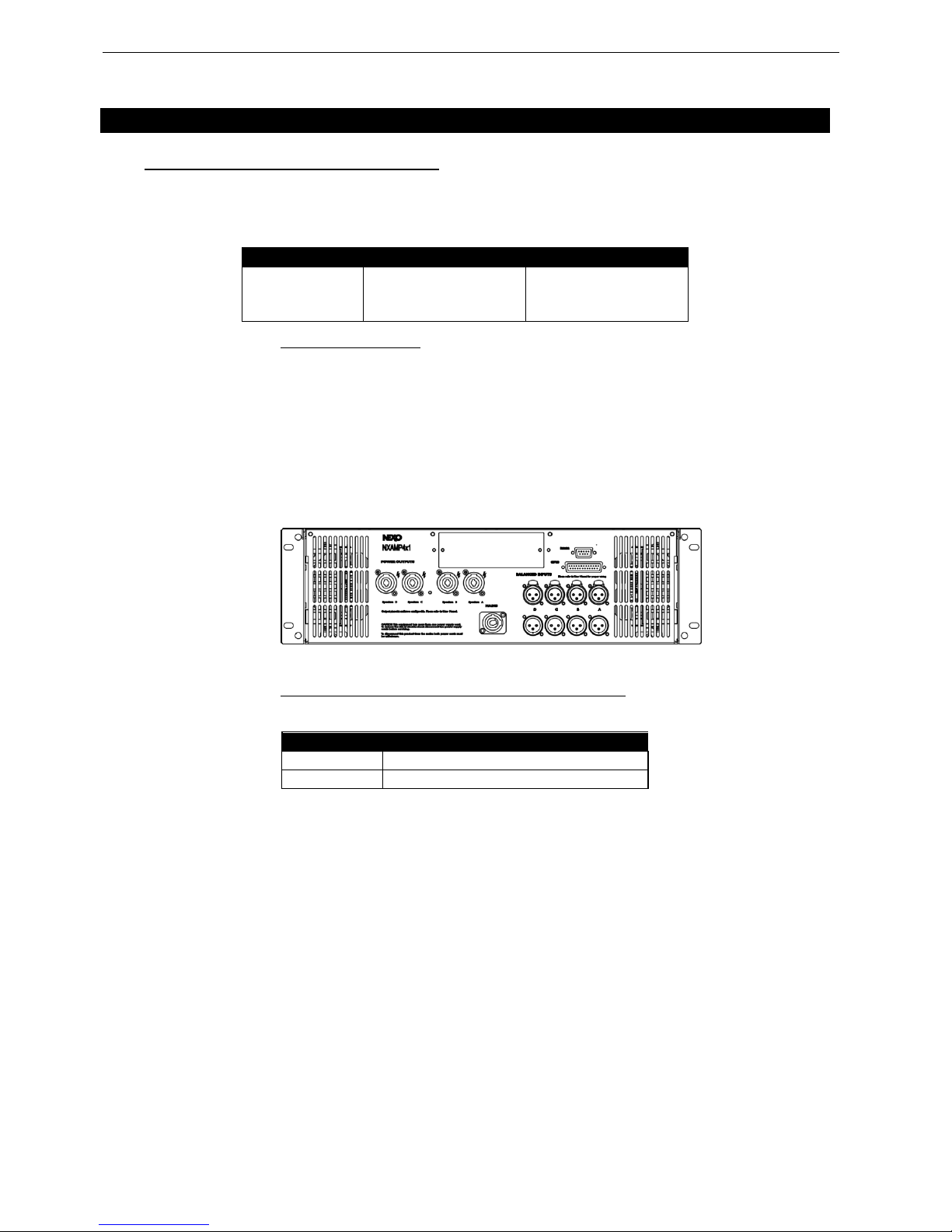
NXAMP connectors 3.1.1
NXAMP4x1 rear panels features:
- 4 analog inputs / outputs (links) on XLR3 connectors;
- 4 digital inputs / outputs on RJ45 connectors with a slot for optional NX-ES104 (EthersoundTM) or NX-
DT104 (DanteTM) cards;
- 4 speaker level outputs on NL4FC connectors.
Figure below shows connectors implementation on the rear panel.
GEO M6 and NXAMP4x1 recommended loading 3.1.2
Passive Mode
3 x GEO M620
1 channel of NXAMP4x1 in 4 channels mode
3 x GEO M6Bass
1 channel of NXAMP4x1 in 4 channels mode
GEO M6 SETUPS ON NEXO TD CONTROLLERS Page 11/62
4 GEO M6 SETUPS ON NEXO TD CONTROLLERS
4.1 NXAMP TDControllers
As of this manual printing date, load 3.22 features the setups listed in below table in the “NEXO
configurations” menu.
NEXO recommended setups
CH1
CH2
CH3
CH4
'M620-LS18 120Hz'
'1-3 Boxes'
LS18 (bridged with CH2)
N/A
M620
M620
'M620-LS18 120Hz'
'4-12 Boxes'
LS18 (bridged with CH2)
N/A
M620
M620
'M620-70Hz'
'4 Ch. 1-3 Boxes'
M620
M620
M620
M620
'M620-70Hz'
'4 Ch. 4-12 Boxes'
M620
M620
M620
M620
'M620-120Hz'
'4 Ch. 1-3 Boxes'
M620
M620
M620
M620
'M620-120Hz'
'4 Ch. 4-12 Boxes'
M620
M620
M620
M620
- Setups “1-3 Boxes” are to be used in small configuration (pole stand, lip fill, under-balcony);
- Setups “4-12 Boxes” are to be used in larger arrays – typically flown;
- Frequency value is high-pass filter cut-off point.
Additionally, “Custom configurations menu” allows to build any combination of NEXO speakers –
including GEO M6Bass with:
- Full phase compatibility from 20 Hz to 20kHz.
- Choice between 85 Hz and 120 Hz X-over point between Nexo LS or RS subwoofers and Geo M6.
NEXO Custom setups
M620 4-12 BOXES 70Hz-20kHz
M620 4-12 BOXES 85Hz-20kHz
M620 4-12 BOXES 120Hz-20kHz
M620 1-3 BOXES 70Hz-20kHz
M620 1-3 BOXES 85Hz-20kHz
M620 1-3 BOXES 120Hz-20kHz
M6B 70Hz-180Hz
M6B 85Hz-180Hz
Please consult www.nexo-sa.com for upgrade releases.
Page 12/62 CONNECTION DIAGRAMS
5 CONNECTION DIAGRAMS
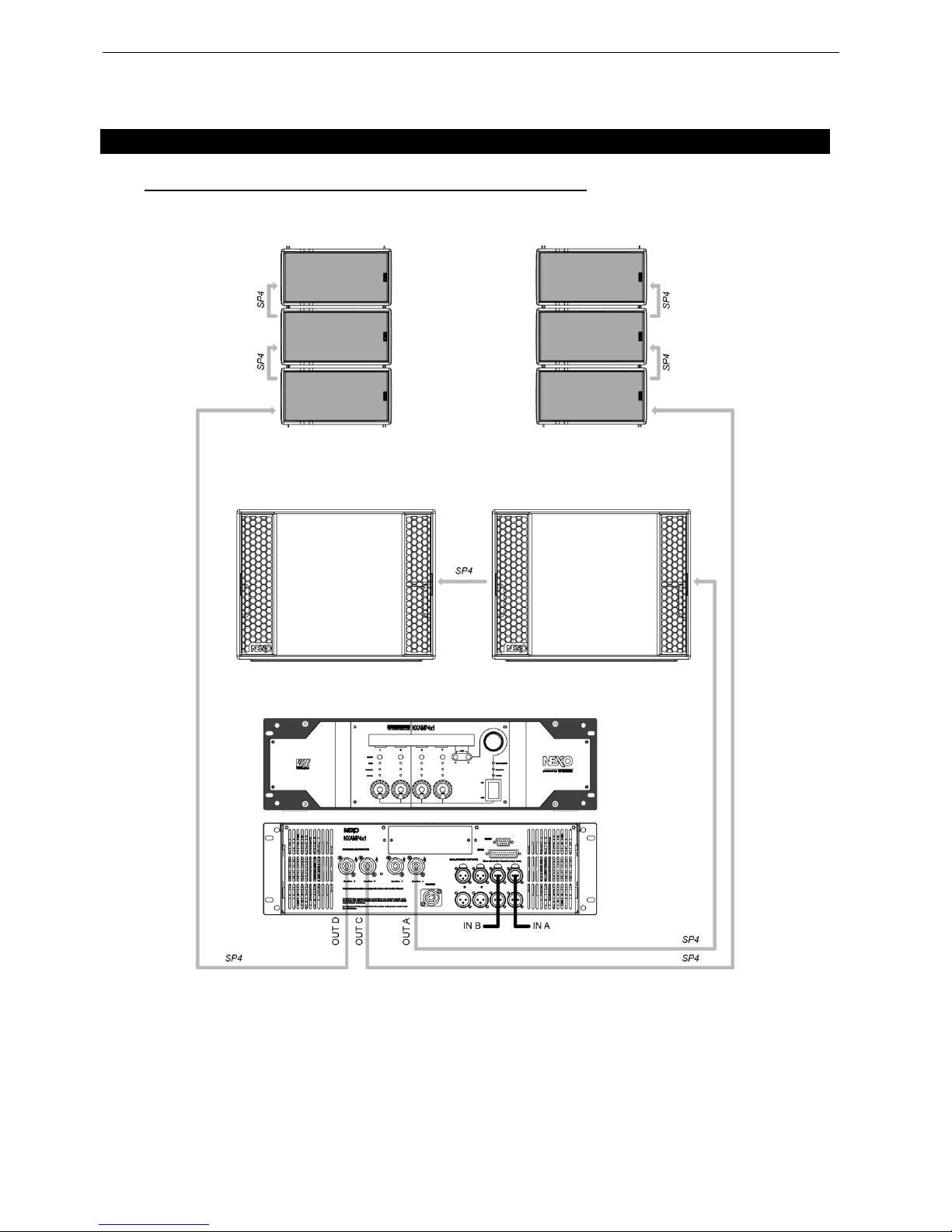
5.1 6 x GEO M620 stereo – 2 x LS18 mono on NXAMP4x1
Channels 1 & 2 are bridge mono for 2xLS18, channel 3 & 4 drive 3 GEO M620 each
CONNECTION DIAGRAMS Page 13/62
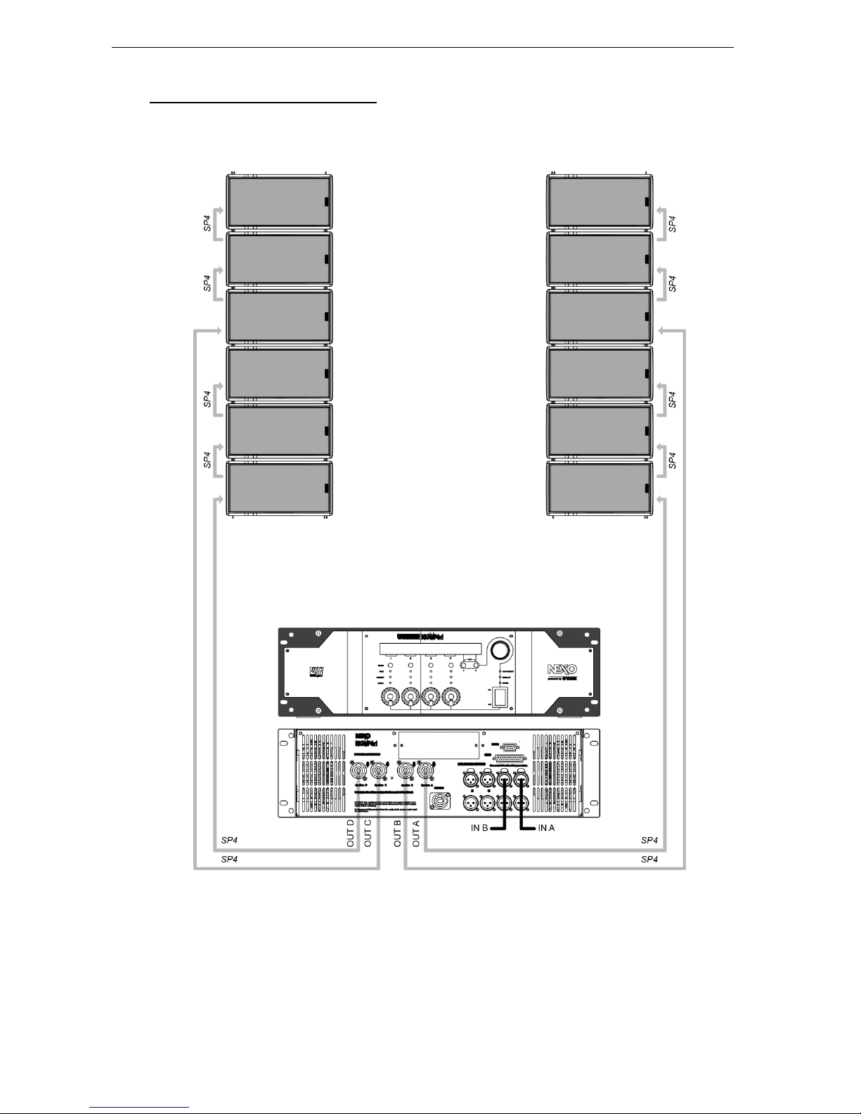
5.2 12 x GEO M620 on NXAMP4x1
Each NXAMP4x1 channel drives 3 GEO M620
Page 14/62 CONNECTION DIAGRAMS
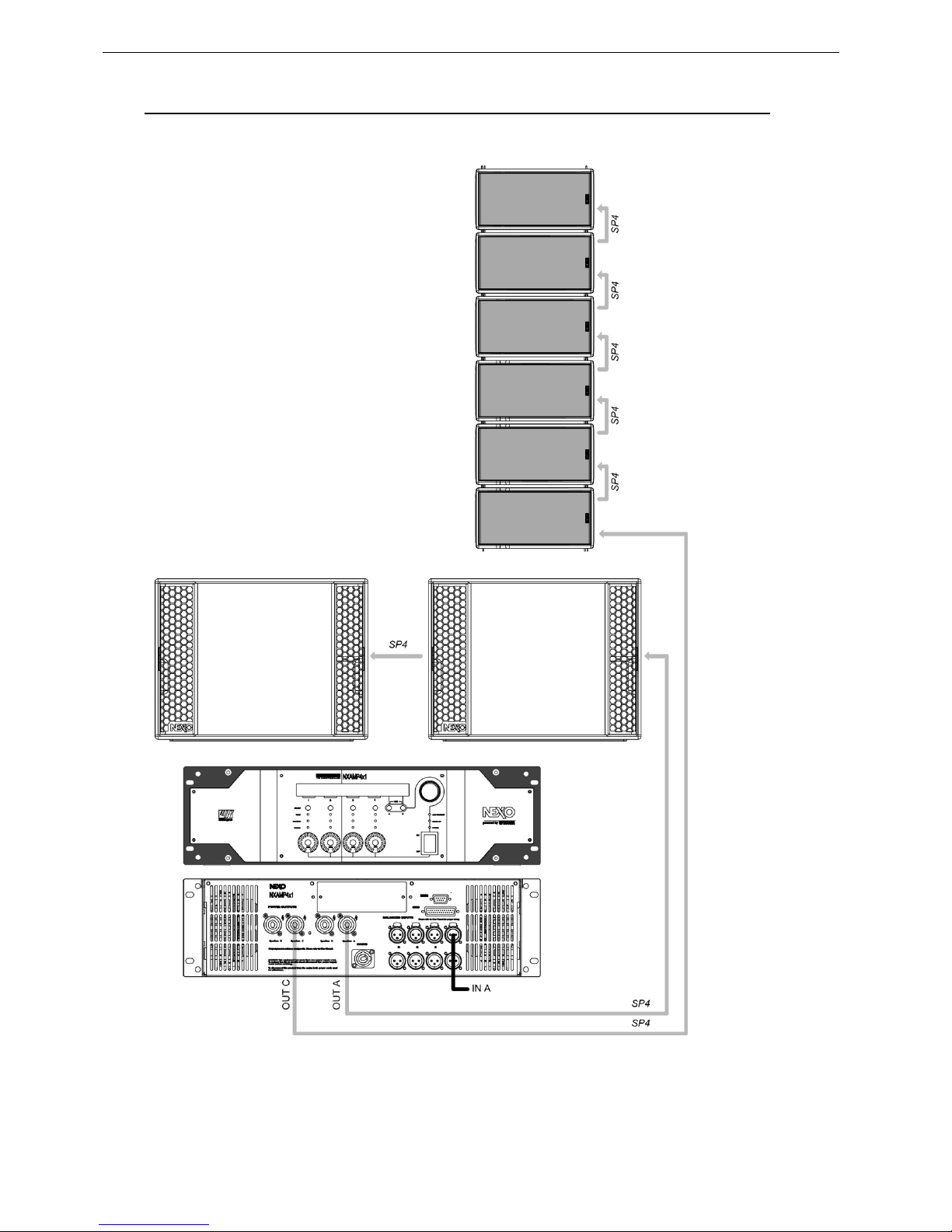
5.3 3 x GEO M620 stereo – 3 x GEO M6B stereo - 2 x LS18 mono on NXAMP4x1
Channels 1 & 2 are bridge mono for 2xLS18, channel 3 drives 3xGEO M6Bass, channel 4 drives 3x
GEO M620.
CONNECTION DIAGRAMS Page 15/62
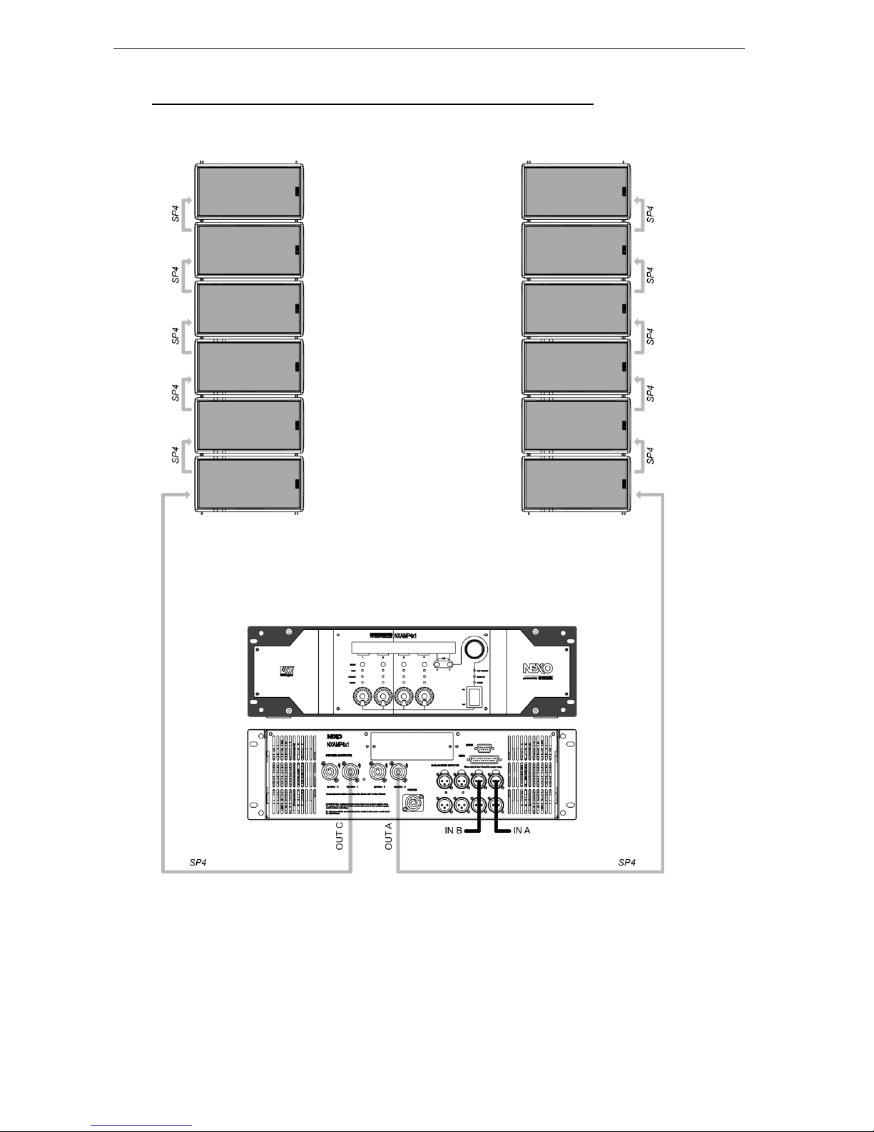
5.4 6 x GEO M620 stereo – 6x GEO M6B stereo on NXAMP4x1
Channels 1 & 3 drive 3xGEO M6Bass each, channels 2&4 drive 3xGEO M620 each.
Page 16/62 NS-1 SIMULATION SOFTWARE
6 NS-1 SIMULATION SOFTWARE
NS-1 software is a R&D simulation tool derived application. It processes measured speaker data with
complex mathematical algorithms to assist the user in optimizing system design. Due to the complexity
of the interaction of multiple cabinets, it is simply not possible to reliably design curved vertical arrays
without using the processing power of a computer to predict the optimum array structure for a given
audience geometry. The design logic is far more complex than looking at a section drawing of the
venue, measuring the overall angle needed to cover the audience from the cluster location, and dividing
by 20 degrees to determine the required amount number of GEO M620 cabinets.
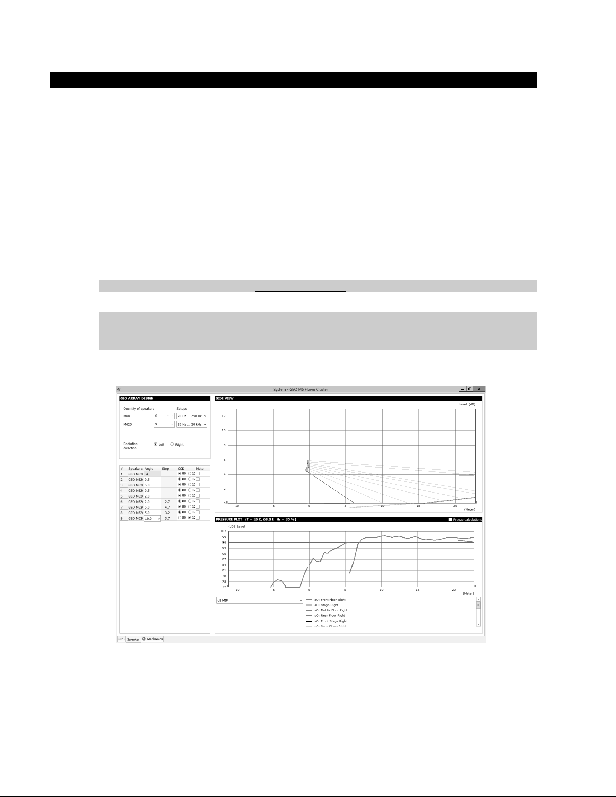
NS-1 is an easy to use tool that allows to shape the energy leaving the cluster to fit the audience. It
predicts pressure levels radiated from the system to ensure enough cabinets are provided for the
application, as well as mechanical constraints for safe flown systems.
In addition, it provides mechanical information for all clusters in agreement with Structural Analysis
Reports (available in the Help section): dimensions, weight, gravity center position, forces, moments,
working load and safety factor.
NS-1 installation package includes all NEXO User Manuals, Structural Analysis Reports and Certificates
PDF files (which can be found in the last section of User Manuals).
NS-1 is a freeware available on www.nexo-sa.com
IMPORTANT
Never install a GEO M6 cluster without checking its acoustical performances and
mechanical safety in NS-1 prior to installation.
Any question or bug report please contact technical@nexo.fr
NS-1 GEO M6 ACOUSTIC PAGE

CONFIGURABLE DIRECTIVITY DEVICE Page 17/62
7 CONFIGURABLE DIRECTIVITY DEVICE
The GEO Wavesource controls dispersion of acoustic energy using an hyperboloid acoustical reflector
in the vertical plane and a diffraction slot in the horizontal plane. The patented Configurable Directivity
Device consists of bolt-on flanges that alter the diffraction slot’s exit flare rate thus increasing the
horizontal coverage from 80° to 120°.
7.1 Installing & removing GEO’s Configurable Directivity flanges
GEO M620 are shipped in the 80° dispersion configuration;
120° flanges is an optional accessory.
To change dispersion in the non-coupling plane to 120°:
- Remove the front grill (TORX15, drawings below);
- Remove the 2 TORX screws per flange on each side of the GEO Waveguide (drawings below);
- Install the 120° flanges with the 2 TORX screws
- Re-install the grid, being careful that the NEXO logo must be on the woofer side.
REMOVING THE GRILL ADDING THE 120° FLANGES
Page 18/62 CONFIGURABLE DIRECTIVITY DEVICE
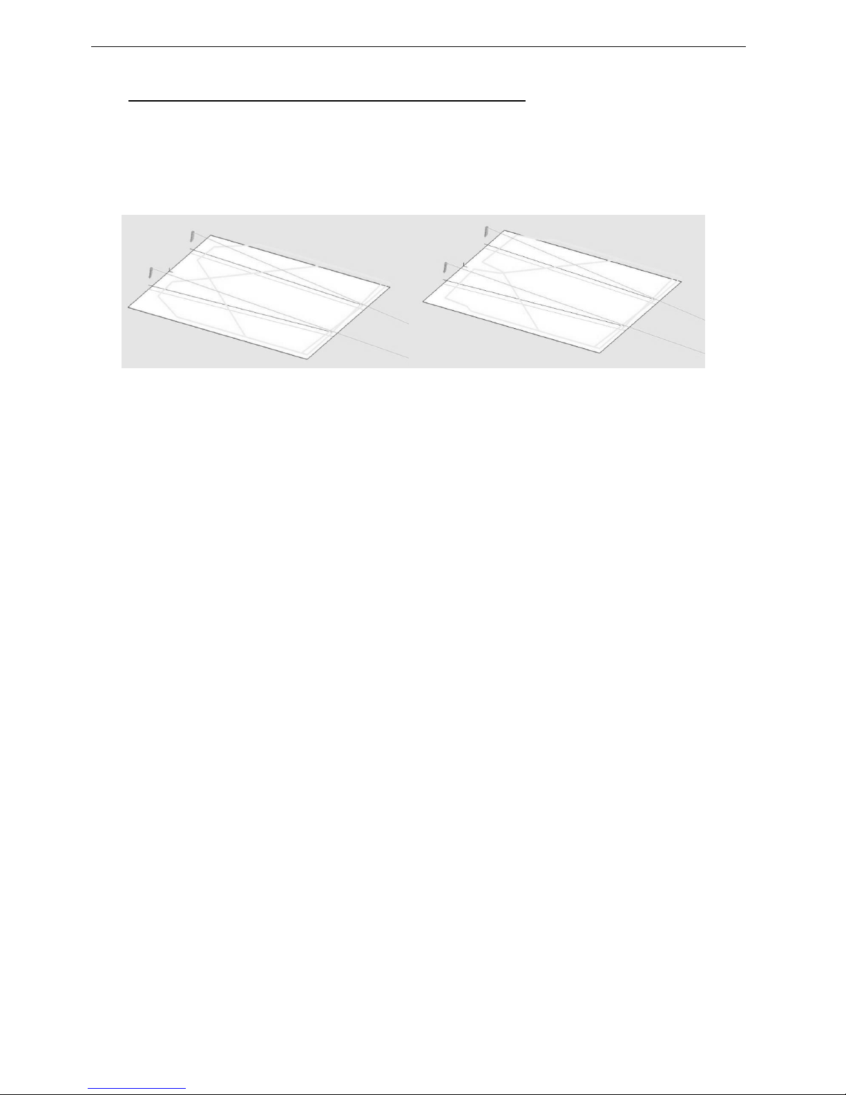
7.2 When & where to use Configurable Directivity flanges
The diagrams show audience area coverage for a stereo system. While a GEO cluster will deliver even
SPL from the front to the rear of this audience area, there are “holes” near the front in the centre and at
the outside edges. We cannot fill the outside coverage gaps without enlarging the centre gap, and vice
versa (left figure below).
If 120° Configurable Directivity Devices are installed at the bottom cabinet of the clusters, coverage will
look more like the pattern in right figure below.
-6dB coverage, all GEO M620 in 80° configuration
-6dB coverage, bottom GEO M620 in 120° configuration
In curved vertical arrays, the 120° Configurable Directivity Device can be used:
- On the bottom row of curved vertical arrays, to fill in coverage gaps in the front rows.
- On all rows of curved vertical arrays, in cases where 120° of horizontal coverage is preferred to 80°.

GEO M6 HARDWARE SETUP PROCEDURE Page 19/62
8 GEO M6 HARDWARE SETUP PROCEDURE
Before proceeding with assembly of GEO M6 arrays, please ensure that the components are present
and undamaged. A component list is appended to this manual. In the event of any shortage, please
contact your supplier.
For maximum efficiency the GEO M6 rigging system requires three experienced persons for set-up:
typically one motor hoist operator, and one operator per side of the array. Good synchronisation and
crosscheck between the operators are key elements for a reliable and safe set-up.
8.1 SAFETY FIRST
GEO M6 Rigging System structural computations and related documents are available in NS-1 or at
NEXO (info@nexo.fr) upon request.
We include this section to remind you of safe practice when flying the GEO M6 system. Please read it
carefully. However, user must always apply his or her knowledge, experience and common sense. If in
any doubt, seek advice from your supplier or NEXO agent.
This manual offers guidance only for GEO M6 loudspeaker systems. References in this manual to other
rigging equipment such as motor hoists, steels, shackles etc. are made to clarify the description of
rigging procedures. The user must ensure that operators are properly trained by other agencies in the
use of these items.
The GEO M6 Rigging System has been optimised for the deployment of curved vertical or horizontal
tangent arrays of GEO M6 loudspeakers. Angle adjustment between cabinets has been limited to
specific settings to ensure correct acoustic coupling.
The GEO M6 Rigging System is a professional precision tool set, and should be handled with extreme
care. Only persons who are fully conversant with the operation of the GEO M6 Rigging System and
provided with suitable safety equipment should deploy GEO Arrays. Misuse of the GEO M6 Rigging
System could lead to dangerous consequences.
Used and maintained correctly, the GEO M6 Rigging System will give many years of reliable service in
portable systems. Please take the time to read and understand this manual. Always use NS-1 to
determine the optimum angle settings for a particular venue, hang point and curved vertical GEO M6
cluster. Applied forces and moments are strongly cabinet quantity and angle configuration dependent.
Cluster configuration must be implemented and validated in NS-1 prior to installation.
Flown Systems Safety 8.1.1
Always inspect all the rigging components and cabinets for damage before assembly. Pay special
attention to the lifting points, and safety clips. If you suspect that any of the components are damaged
or defective, DO NOT USE THE AFFECTED PARTS. Contact your supplier for replacements.
Read this manual carefully. Also be familiar with the manuals and safe working procedures for any
ancillary equipment that will be used with the GEO M6 Rigging System.
Applied forces and moments are strongly cabinet quantity and angle configuration dependent. Cluster
configuration must be implemented and validated in NS-1 prior to installation.
Ensure that all local and National regulations regarding the safety and operation of flying equipment are
understood and adhered to. Information on these regulations can usually be obtained from Local
Government Offices.
When deploying a GEO M6 system always wear protective headwear, footwear and eye protection.
Do not allow inexperienced persons to handle a GEO M6 system. Installation personnel should be
trained in loudspeaker flying techniques and should be fully conversant with this manual.
 Loading...