

Page 1
NEXO 45°N 12
Line Monitor
User Manual
45°N-12 User Manual V1.01b
Date: 06/01/2011
Page 2
Page 2/26 INTRODUCTION
PLEASE READ CAREFULLY BEFORE PROCEEDING
BASIC PRECAUTIONS
Do not open the speaker system or attempt to disassemble the internal parts or modify them in any
way. The speaker system contains no user-serviceable parts. If it should appear to be malfunctioning
or damaged, discontinue use immediately and have it inspected by qualified NEXO service personnel.
Water exposure: Do not expose the speaker system to direct rain; do not use it near water or in wet
conditions. Do not place containers with liquid on speaker system as they might spill into openings. If
any liquid such as water seeps into the speaker system, have it inspected by qualified NEXO
personnel.
SYSTEM DEPLOYMENT SAFETY RULES
Read User Manual before deployment. Before use of enclosed speaker system,
please ensure that anyone involved in system deployment understands the rigging –
stacking – pole mounting safety rules as described in the speaker system User Manual.
Failure to do this exposes people to potential injury or death.
Always consult qualified NEXO personnel if the device installation requires construction work and make
sure to observe the following precautions:
Mounting precautions
- choose mounting hardware and an installation location that can support the weight of the speaker
system;
- do not use speaker system handles for suspended installation;
- do not expose speaker system to excessive dust or vibration, or extreme cold or heat to prevent
possibility of component damage;
- do not place the speaker system in an unstable position from which it might fall accidentally;
- if speaker systems uses a stand, ensure that stand specifications are adapted, and that stand
height does not exceed 1.40m/55”; never move the stand while the speaker is in position.
Connection and powering precautions
- remove all connected cables before moving the speaker system;
- turn off AC power of all power amplifier units before connecting the speaker system;
- when turning on the AC power to the audio system, always turn on the power amplifier last; when
turning the AC power off, always turn off the power amplifier first;
- when used in cold conditions, a gradual power ramp up should applied to the system on an 5 mn
period to allow the loudspeaker components to stabilize during the very first minutes of usage.
Inspect the speaker system periodically.
Page 3
INTRODUCTION Page 3/26
SAFETY INSTRUCTIONS FOR NEXO TD CONTROLLERS
NEXO ANALOGUE PSTDCONTROLLERS, NX242 DIGITAL CONTROLLER,
NXAMP4x1 AND NXAMP4x4 POWERED CONTROLLERS ARE CLASS 1
APPARATUS AND MUST BE EARTHED.
THE GREEN AND YELLOW WIRE OF THE MAINS CORD MUST ALWAYS BE CONNECTED TO AN
INSTALLATION SAFETY EARTH OR GROUND. THE EARTH IS ESSENTIAL FOR PERSONAL
SAFETY AS WELL AS THE CORRECT OPERATION OF THE SYSTEM, AND IS INTERNALLY
CONNECTED TO ALL EXPOSED METAL SURFACES.
- Read these instructions.
- Keep these instructions.
- Heed all warnings.
- Follow all instructions.
- Do not use this apparatus near water.
- Clean only with dry cloth.
- Do not block any ventilation openings. Install in accordance with the manufacturer’s instructions.
- Do not install near any heat sources such as radiators, heat registers, stoves, or other apparatus
(including amplifiers) that produce heat.
- Do not defeat the safety purpose of the polarized or grounding-type plug. A polarized plug has two
blades with one wider than the other. A grounding type plug has two blades and a third grounding
prong. The wide blade or the third prong are provided for your safety. If the provided plu g does not
fit into your outlet, consult an electrician for replacement of the obsolete outlet. (US market)
- Protect the power cord from being walked on or pinched particularly at plugs, convenience
receptacles, and the point where they exit from the apparatus.
- Only use attachments/accessories specified by the manufacturer.
- Unplug this apparatus during lightning storms or when unused for long periods of time.
- Refer all servicing to qualified service personnel. Servicing is required when the apparatus has
been damaged in any way, such as power-supply cord or plug is damaged, liquid has been spilled
or objects have fallen into the apparatus, the apparatus has been exposed to rain or moisture, does
not operate normally, or has been dropped.
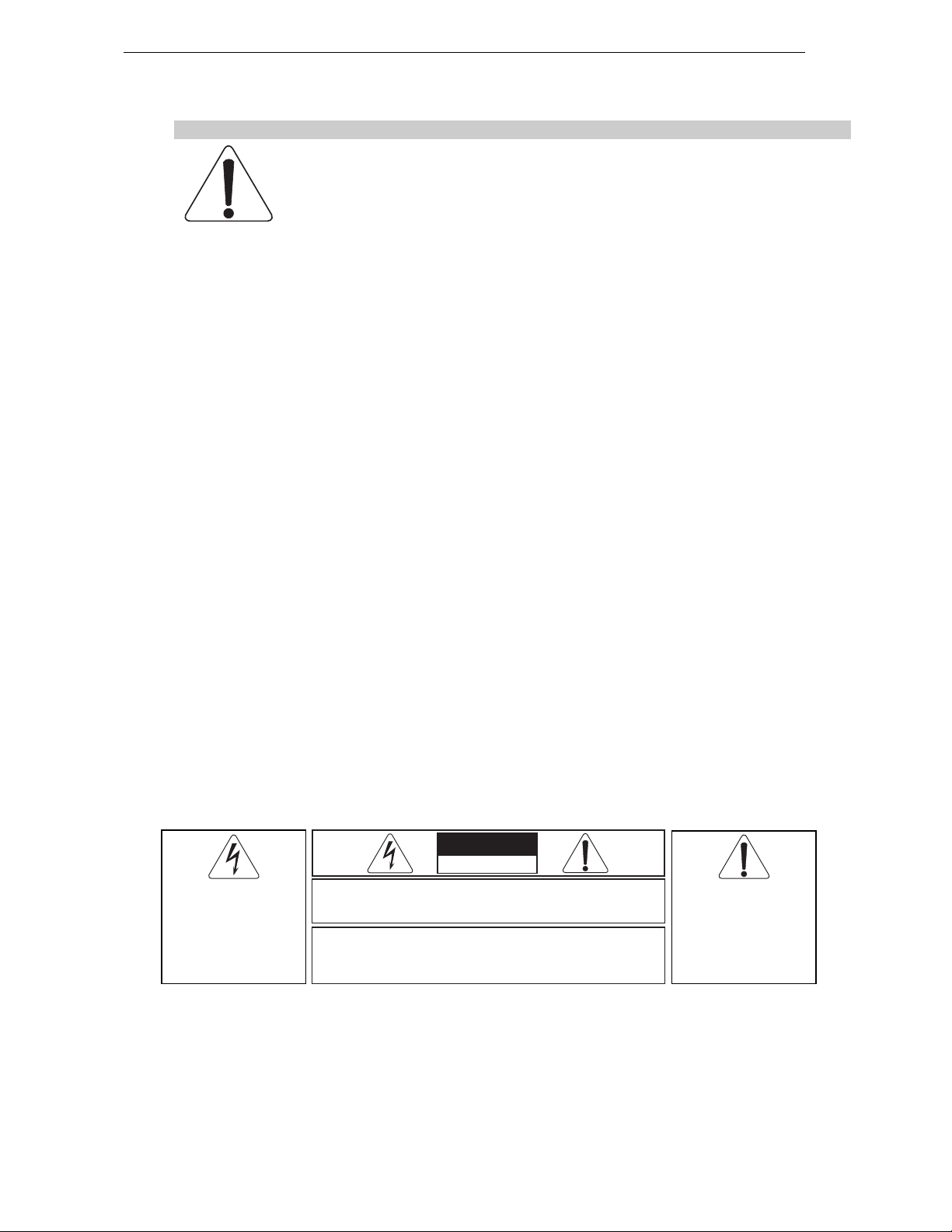
The lightning flash with arrowhead
symbol, within an equilateral triangle
is intended to alert the user to the
presence of uninsulated “dangerous
voltage” within the product's
enclosure that may be of sufficient
magnitude to constitute a risk of
electric shock to persons.
CAUTION
RISK OF ELECTRIC SHOCK
DO NOT OPEN
WARNING: To reduce the risk of fire or electric shock,
do not expose this apparatus to rain or moisture.
To avoid electrical shock, do not remove covers.
Dangerous voltages exist inside.
Refer all servicing to qualified personnel only.
The exclamation point within an
equilateral triangle is intended to
alert the user to the presence of
important operating and
maintenance (servicing) instructions
in the literature accompanying
the appliance.
Page 4
Page 4/26 INTRODUCTION
HIGH SOUND PRESSURE LEVELS
Exposure to extremely high noise levels may cause permanent hearing loss.
Individuals vary considerably in susceptibility to noise-induced hearing loss but nearly
everyone will lose some hearing if exposed to sufficiently intense noise for a sufficient
period of time. The U.S. Government’s Occupational and Health Administration (OSHA)
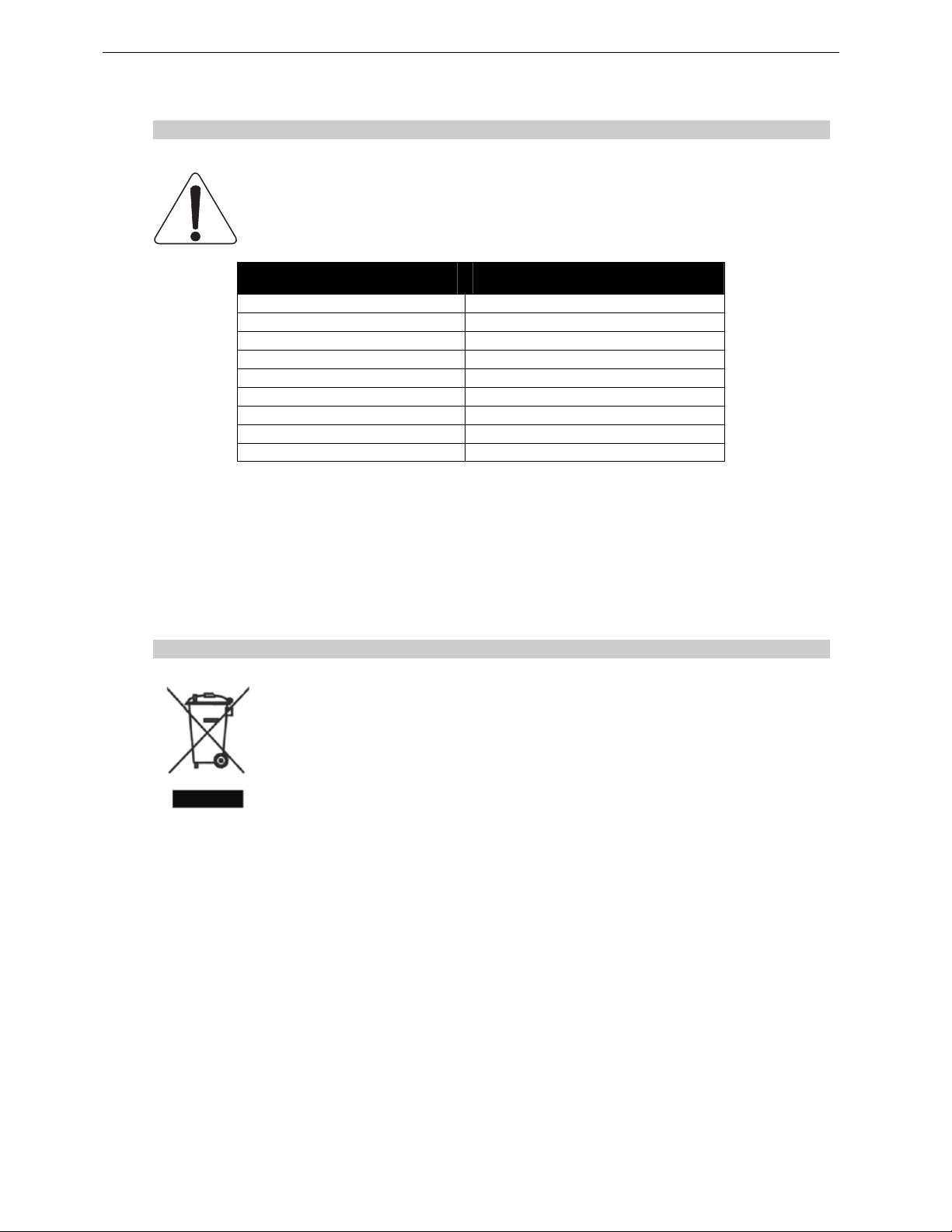
has specified the following permissible noise level exposures: Sound Duration Per
Day In Hours Sound Level dBA, Slow Response
8 90
6 92
4 65
3 97
2 100
1 ½ 102
1 105
½ 110
¼ or less 115
According to OSHA, any exposure in excess of the above permissible limits could result in some
hearing loss. Ear plugs or protectors to the ear canals or over the ears must be wor n when operating
this amplification system in order to prevent permanent hearing loss, if exposure is in excess of the
limits as set forth above. To ensure against potentially dangerous exposure to high sound pressure
levels, it is recommended that all persons exposed to equipment capable of producing high sound
pressure levels such as this amplification system be protected by hearing protectors while this unit is in
operation.
DISPOSAL OF OLD ELECTRICAL & ELECTRONIC EQUIPMENT
This symbol on the product or on its packaging indicates that it shall not be treated
as household waste. Instead it shall be handed over to the applicable collection
point for the recycling of electrical and electronic equipment. By ensuring this
product is disposed of correctly, you will help prevent potential negative
consequence for the environment and human health, which could otherwise be
caused by in appropriate wast e handling of thi s product. The recy cling of material s
will help to conserve natural resources. For more detailed information about
recycling of this pr oduct, please co ntact your loc al city office , your hous ehold waste
disposal service or the shop where you purchased the product.
Page 5

INTRODUCTION Page 5/26
CONTENTS
1 Introduction ................................................ ............................................................................................... 6
2 45N12 General Set-up Instructions.................................. ......... ..... ..... .... ......... ..... .... ..... ......... .... ............. 8
2.1 Speaker connection............................................................................................................................ 8
2.1.1 45°N-12 Connector Panel .......................................................................................................... 8
2.1.2 Configuring 45N12 for Passive or Active Mode.......................................................................... 8
2.1.3 Cabling....................................................................................................................................... 9
3 Amplifier Selection for use with 45°N-12 ............................................................................................... 11
3.1 45N12 recommended amplification................................................................................................... 11
3.1.1 Current rating........................................................................................................................... 11
3.1.2 Amplifier settings...................................................................................................................... 11
3.2 45°N-12 and NXAMP TDControllers......... .... ..... ..... ......... .... ..... ......... ..... .... ..... ......... .... ..... ......... ......13
3.2.1 NXAMP connectors.................................................................................................................. 13
3.2.2 45°N-12 and NXAMP recommended configurations................................................................ . 13
4 Connection diagrams.............................................................................................................................. 14
4.1 45°N-12 / NXAMP4x1 - Bridge Stereo – Active mode....................................................................... 14
4.2 45°N-12 / NXAMP4x1 - Bridge Stereo – Passive mode............ ....................................................... . 15
4.3 45N12 / NXAMP4x4 - 4 Channels – Active Mode............................................................................. 16
4.4 45°N-12 / NXAMP4x4 - 4 Channels – Passive Mode........................................................................ 17
4.5 45°N-12 / NX242-ES4 – Active Mode......................... ......................................................................18
4.6 45°N-12 / NX242-ES4 – Passive Mode............................................................................................ 19
5 Application guidelines............................................................................................................................ 20
5.1 SAFETY FIRST................................................................................................................................ 20
5.2 45°N-12 Coverage.... ..... .... ......... ..... .... .......... .... ..... ......... .... ..... ......... ..... .... ......... ..... .... ..... ............... 20
5.3 Handling 45 N-12 on stage............................................................................................................... 21
5.4 Stage monitoring applications................................. .... ..... .... ......... ..... ..... .... ......... ..... .... ..... ............... 22
5.5 Testing and Maintenance of the system ....... ....................................................................................23
6 45°N-12 Technical Specifications .......................................................................................................... 24
6.1 System specifications............................................................................................... ........................ 24
6.2 Dimensions................................................................. ...................................................................... 25
6.3 Component List ................................................................................................................................ 25
7 USER NOTES..................................... ...................................................................................................... 26
Page 6
Page 6/26 INTRODUCTION
1 INTRODUCTION
Thank you for selecting a NEXO 45°N-12 floor monitor.
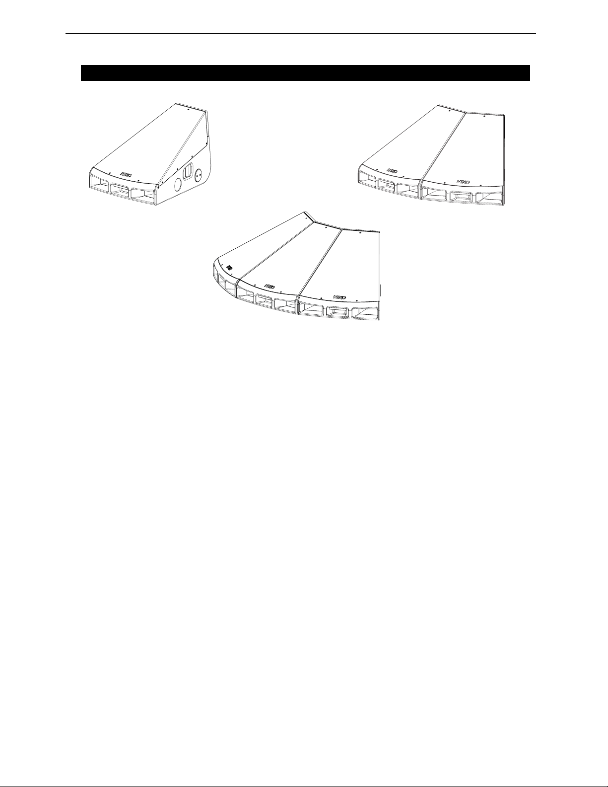
NEXO’s 45°N-12 monitor loudspeaker is the first product based on a radical new concept in stage
sound – that of line monitoring.
The revolutionary NEXO 45°N-12 wedge monitor brings all the benefits of line-array technology to the
stage.
It draws on NEXO’s patented Hyperbolic Reflective Wavesource which is used throughout the GEO
range of high-performance loudspeakers. The design works by wavesourcing, creating virtual ac oustic
sources behind the enclosure itself and below the stage, using reflection rather than coercion to
determine the shape of the wavefront.
Unlike a conventional high frequency waveguide in which the exit is rectangular, the NEXO monitor’s
waveguide enables cabinets to be linked together to form arrays without interferences between
wavefronts.
Practical benefits for stage monitoring applications are:
- steady frequency in coverage area;
- higher SPL and feedback threshold;
- sharp side attenuation;
- coverage and SPL scalability.
This manual is intended to provide you with necessary and useful information about your NEXO 45°N12 floor monitor system.
Page 7
INTRODUCTION Page 7/26
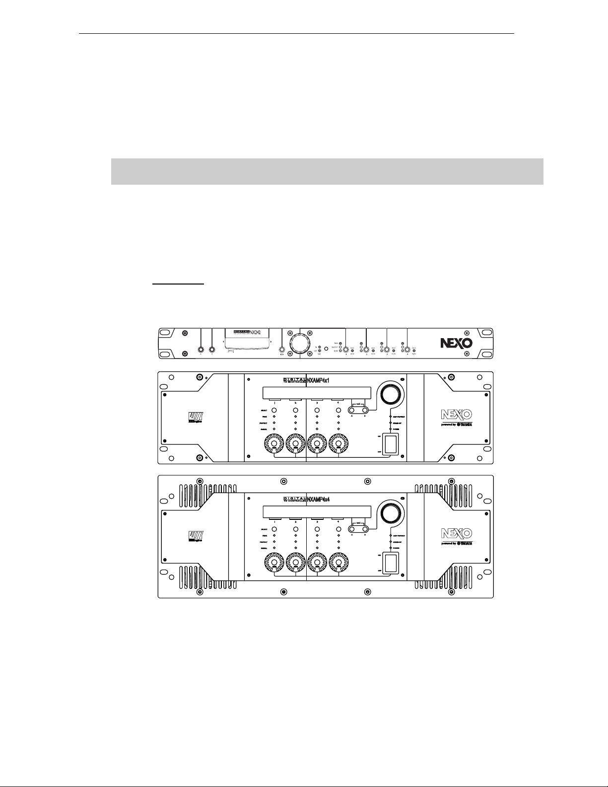
As for all NEXO systems, NEXO 45°N-12 is controlled, powered and monitored by dedicated NEXO
TDControllers:
NX242-ES4 Digital TDController provides comprehensive control of N12 line monitors in multiple
configurations. It allows EthersoundTM digital audio networking, as well as remote control for all units in
the network. It has 2 analogue / 4 digital inputs and 4 analogue / 4 digital outputs.
IMPORTANT
NX242 must be equipped with NX-Tension Card (NX-ES4) to access N12 setups
NXAMP4x1 and NXAMP 4x4 are Powered Digital Controllers, providing full control and amplification for
45N12 in multiple configurations. Both devices feature 4 analogue inputs and 4 speaker outputs. When
equipped with optional card, 4 digital inputs in EthersoundTM digital audio network format as well as
remote control for all units in the net work become avai lable.
For a complete description of these controllers, please refer to User Manuals. The NX242 and NXAMP
DSP algorithms and parameters are fixed in software and updated regularly: Please consult the NEXO
web site (www.nexo.fr
) for the latest software releases.
GeoD Passive mode
Crossover 80Hz
Page 8
Page 8/26 45N12 GENERAL SET-UP INSTRUCTIONS
2 45N12 GENERAL SET-UP INSTRUCTIONS
2.1 Speaker connection
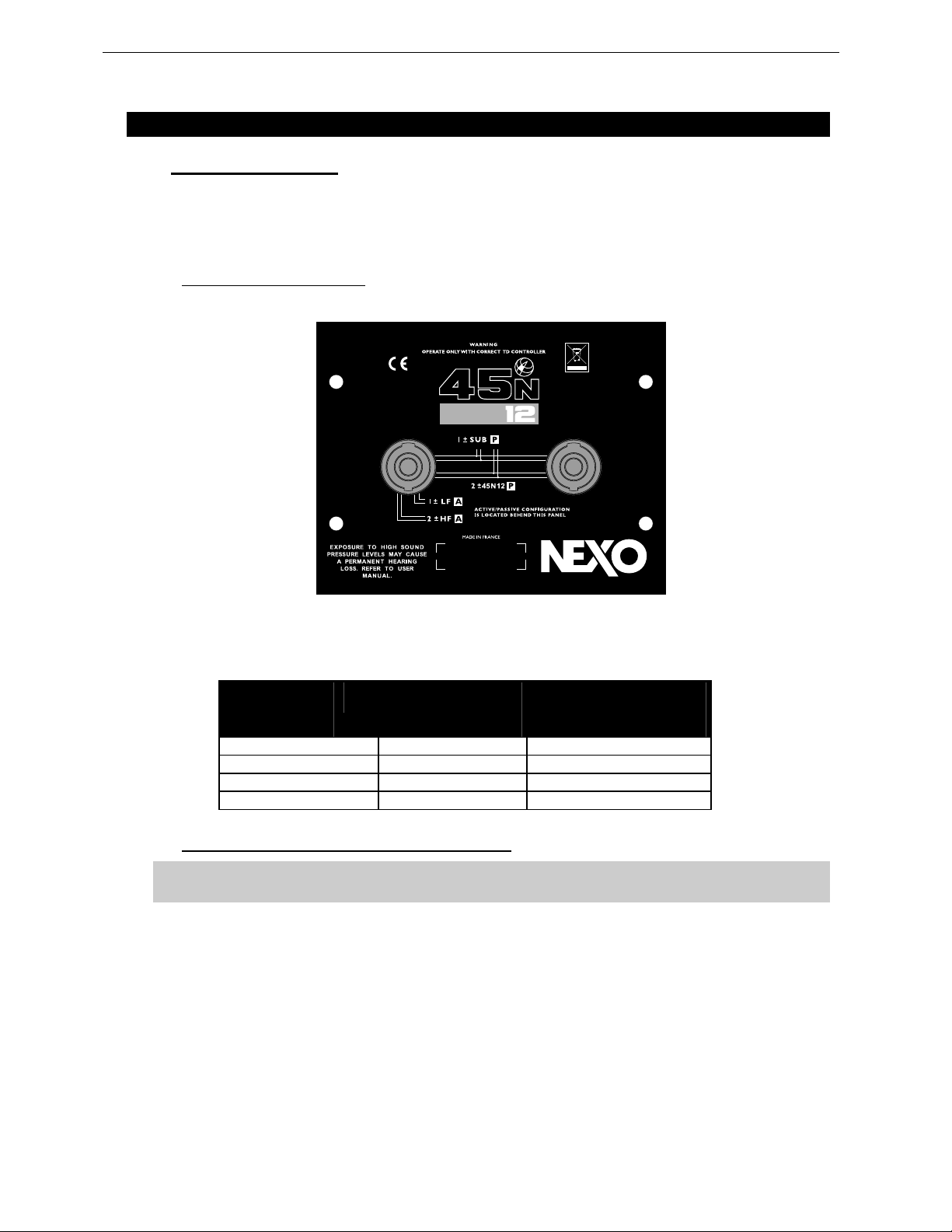
NEXO 45°N-12 are connected with Speakon NL4FC plugs (not supplied). A wiring diagram is printed on
the connection panel located on the back of each cabinet. The 4 pins of the 2 Speakon sockets
identified in / out are connected in parallel within the enclosure.
Either connector can be used to connect amplifier or to link to an additional 45N12 cabinet.
2.1.1 45°N-12 Connector Panel
Connectors are wired as follows:
Speakon
Connector
1(-)
1(+)
2(-)
2(+)
Passive
Ö
Ö
Ö
Ö
Not Connected 45N12 LF (-)
Not Connected 45N12 LF (+)
45N12 (-) 45N12 HF (-)
45N12 (+) 45N12 HF (+)
Mode
Active
Mode
2.1.2 Configuring 45N12 for Passive or Active Mode
IMPORTANT
45N12 are factory configured in active mode
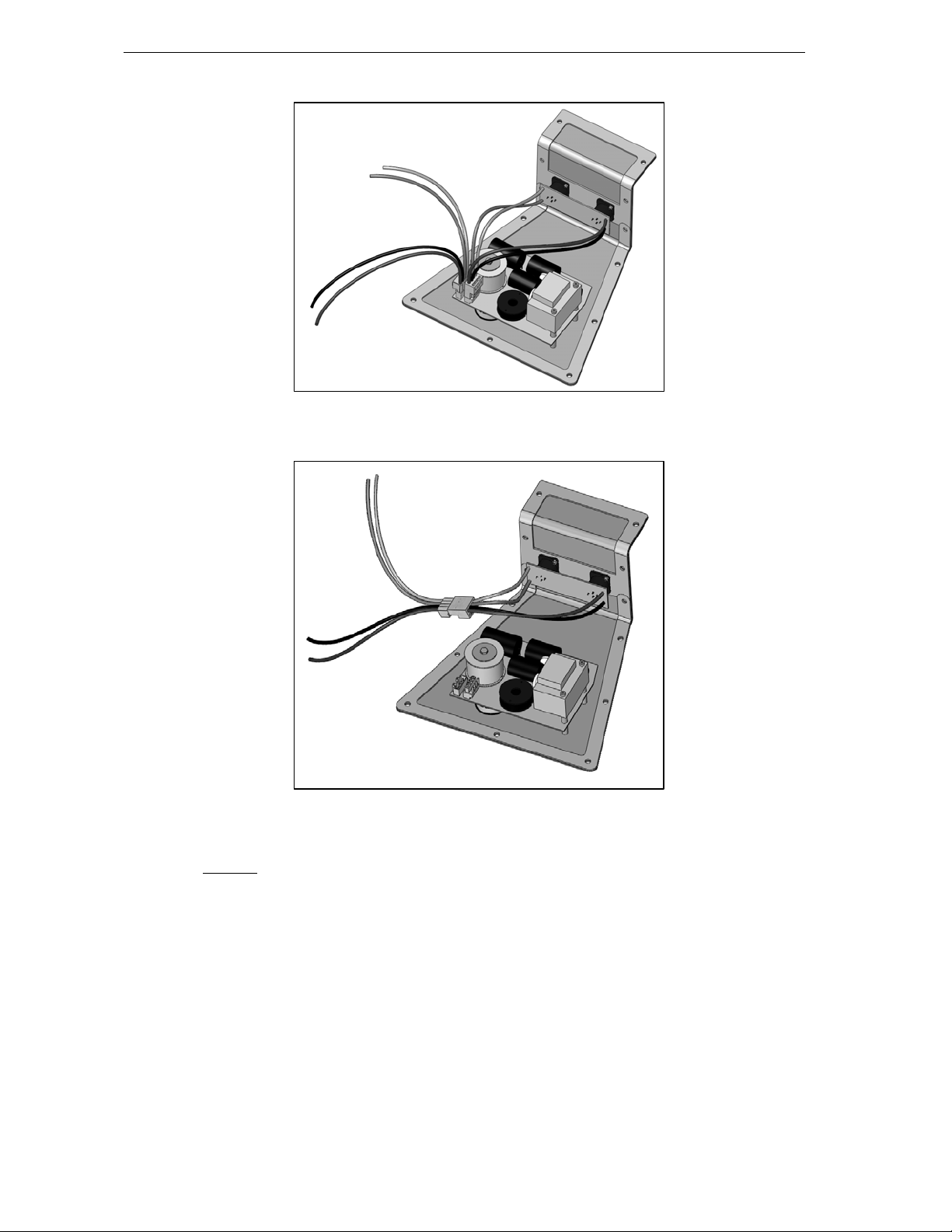
In order to c hange active or passive configuration:
- remove the TORX screws that hold the rear/bottom metal panel;
- remove the rear/bottom metal panel to access passive network WAGO connectors.
In Passive Mode, WAGO connector should be inserted in “Passive In”, and speakers WAGO
connectors should be inserted in connector “Passive Out”.
In Active Mode, WAGO Connector should be directly connected to speakers via speakers WAGO
connectors (passive filter is then bypassed).
Page 9
45N12 GENERAL SET-UP INSTRUCTIONS Page 9/26
HF -
HF +
LF -
LF +
PASSIVE MODE CONFIGURATION
HF + HF -
LF -
LF +
ACTIVE MODE CONFIGURATION
2.1.3 Cabling
NEXO recommen ds the exc lusive us e of multi-c onductor cables to co nnect the s ystem: the c able kit i s
compatible with all the cabinets, and there is no possible confusion between LF and HF sections.
Cable choice consists mainly of selecting cables of the correct sectional dimension (size) in relation to
the load resistance and the cable length. Too small a cable section will increase both its serial
resistance and its capacitance; this reduces the electrical po wer delivered to the loudspeaker and can
also induce response (damping factor) variations.
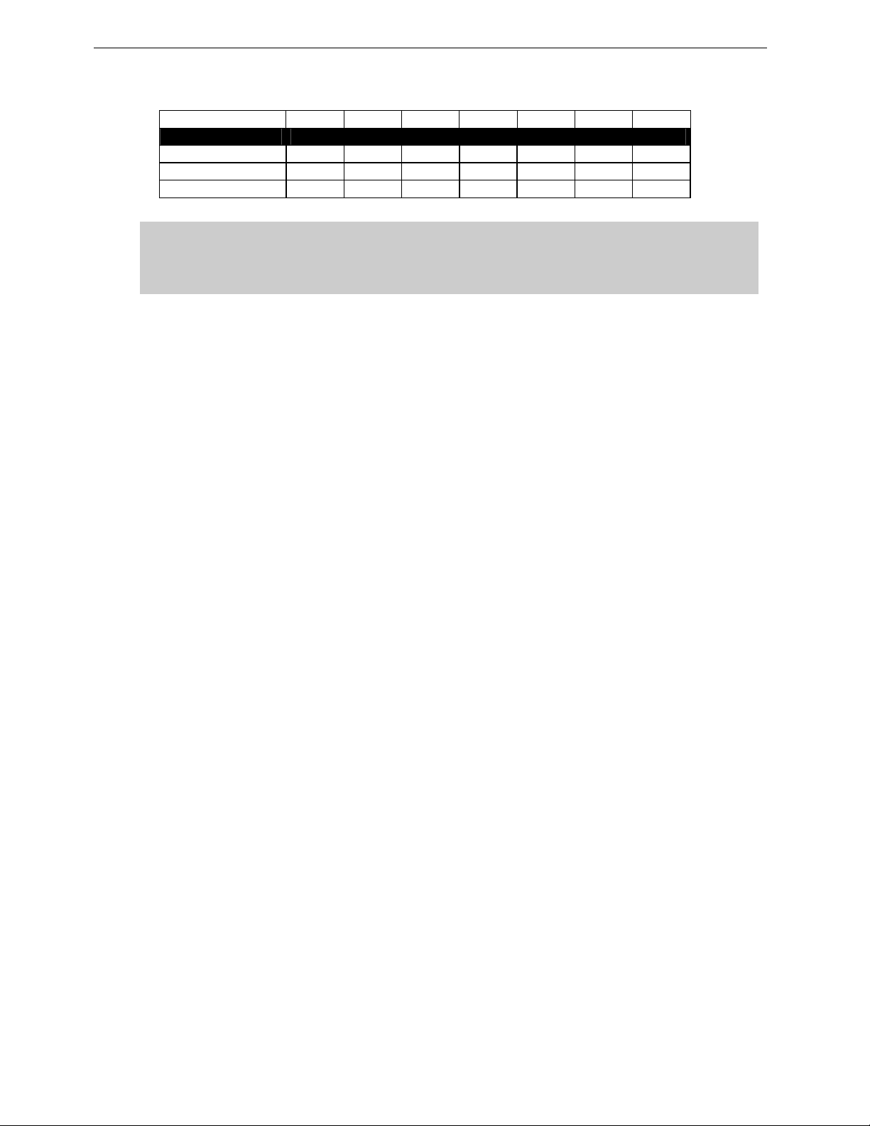
For a serial resistance less or equal to 4% of the load impedance (damping factor = 25), the maximum
cable length is given by:
L
= Z x S S in mm2, Z in Ohm, L
max
in meters
max
Page 10
Page 10/26 45N12 GENERAL SET-UP INSTRUCTIONS
The table below indicates these values, for 3 common sizes.
Load Impedance (Ω)
Cable section Maximum Length (meters)
1,5 mm² (AWG #14) 3 4.5 6 9 12 18 24
2,5 mm² (AWG #12) 5 7.5 10 15 20 30 40
4 mm² (AWG #10) 8 12 16 24 32 48 64
2 3 4 6 8 12 16
IMPORTANT
Long speaker cables induce capacitive effects – up to hundreds of pF depending on the
quality of the cable - with a low-pass effect on high frequencies. If long speaker cables
must be used, ensure that they do not remain coiled while in use.
Page 11
AMPLIFIER SELECTION FOR USE WITH 45 N-12 Page 11/26
3 AMPLIFIER SELECTION FOR USE WITH 45°N-12
NEXO recommends high power amplifiers in all cases. Budget constraints are the only reason to select
lower power amplifiers. A lower power amplifier will not reduce the chances of driver damage due to
over-excursion, and may actually increase the risk of thermal damage due to sustained clipping. If an
incident occurs on an installation without protection, the fact that amplifiers only generating half their
rated output power (-3dB) are used will not change anything in respect of possible damage. This is due
to the fact that the RMS power handling of the weakest component in the system is always 6 to 10 dB
lower than the amplifier rating.
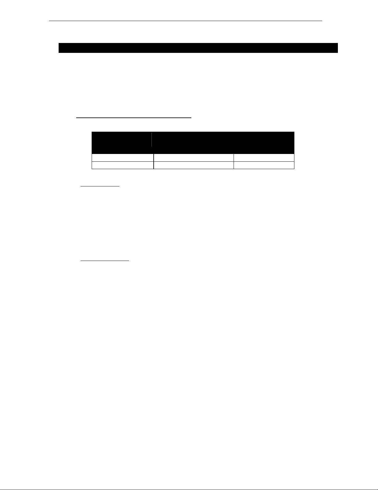
3.1 45N12 recommended amplification
Nexo recommends amplifiers in agreement with table below:
Recommended
Amplifier#
45N12 Passive Mode 1200 to 2000 W / 8 Ohms
45N12 Active Mode 1000 to 1500 W / 8 Ohms 250 to 500 W / 16 Ohms
Channel 1
LF in Active Mode or
LF+HF in Passive Mode
Channel 2
HF in Active Mode
3.1.1 Current rating
It is very important that the amplifier behaves correctly under low load conditions. A speaker system is
reactive by nature: on transient signals like music it will require four to ten times more instantaneous
current than its nominal impedance would indicate. Amplifiers are generally specified by continuous
RMS power into resistive loads, however the only useful information about current capacity is the
specification into a 2 Ohm load. It is possible to perform an amplifier listening test by loading the amps
with twice the number of cabinets considered for the application ( 2 speakers per channel instead of one,
4 instead of 2) and running the amps up to the onset of clipping. If the signal does not noticeably
deteriorate, the amplifier is well adapted (overheating after approximately ten minutes is normal but
thermal pro tection must not operate too quickly after starti ng this test).
3.1.2 Amplifier settings
Gain value
Gain is the key to correct alignment of the system. It is especially important to know the gain of all
amplifiers used in your set-up. The tolerance should be about ±0.5 dB. In practice this can be difficult to
achieve because:
Some amplifier brands have an identical input sensitivity for models of different power rating (this infers
a different voltage gain for each model). For example, a range of amplifiers with different power outputs,
all having a published input sensitivity of 775mV/0dBm or 1.55V/+6dBm, will have a wide range of
actual gains – the higher the power, the greater the gain.
Various other brands may offer constant gain but only within a given product range, for example they
may fit fixed input sensitivity only on their semi-professional amps.
Even if a manufacturer applies the constant gain rule to all models, the value selected will not
necessarily be the same as that chosen by other manufacturers.
Some products can exhibit manufacturing tolerances for the same model of ±1dB or more. Some
amplifiers may have been modified, possibly without any label indicating the new values. Others may
have gain switches fitted internally where it is impossible for the user to verify the actual setting without
opening the amplifier casing.
In cases where you don't know the gain of your amplifier (or want to check it) please follow this
procedure:
- unplug any loudspeakers from the amplifier outputs
- feed a sine wave at 1000Hz at a known voltage (~ 0.5V) to the input of the amplifier under test
Page 12
Page 12/26 AMPLIFIER SELECTION FOR USE WITH 45 N-12
- measure the volt ag e at the out put of the amplifi er
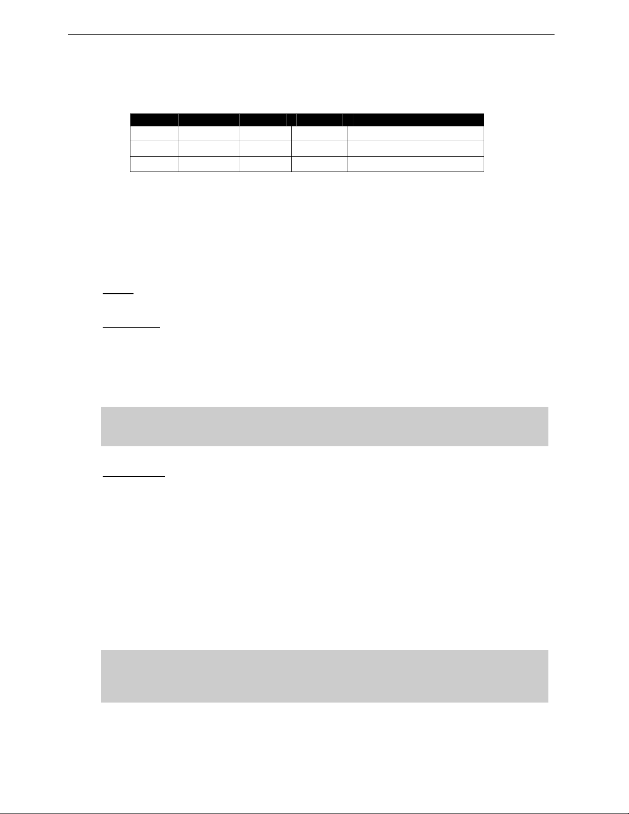
- calculate the gain using the formula Gain = 20 * LOG10(Vout/Vin).
Some examples:
Vin / Gain 20dB 26dB 32dB 37dB (1.4V sensitivity / 1350Wrms)
0.1 V 1 V 2 V 4 V 7.1 V
0.5 V 5 V 10 V 20 V 35.4 V
1 V 10 V 20 V 40 V 70.8 V
Remember that constant sensitivity settings will give a different gain value when the amplifier power is
different.
NEXO recommends 26 dB gain amplifiers, as it is at the same time adequately low and quite common
amongst amplifier manufacturers. This gain setting improves signal to noise ratio and allows all
preceding electronic equipment, including the NX242-ES4 TDcontroller, to operate at optimum level.
Using a high gain amplifier will raise the noise floor proportionally.
Operating Mode
Most two channel amplifiers available on the pro-audio market have the following operating modes:
Stereo:
two fully independent channels deliver identical power into identical loads
NEXO recommends Stereo Mode for all amplifier channels feeding 45°N-12 monitors.
Bridge-Mono:
the second signal channel processes the same input as the first channel, but with
reversed phase. The (single) load is connected between the two positive channel outputs using a
suitable connection. While the total output of the amplifier remains the same, the available output
voltage, the minimum impedance that can be connected and the voltage gain are doubled as compared
with stereo operation. Typically, only channel 1 input is active. Positive and negative output connections
vary depending on amplifier manufacturers.
NEXO does not recommend Bridge Mono Mode unless amplifier power is clearly not sufficient.
IMPORTANT
When in Bridge-Mono mode, check your amplifier user manua l for proper connection of
outputs 1(+) and (2+) in relation to input phase.
Parallel-mono:
the output terminals of the two channels are configured in parallel using an internal relay.
The (single) load is connected either to the output of channel 1 or to that of channel 2 (as if in stereo).
While the total output of the amplifier remains the same the output voltage level is also the same as in
stereo mode. The minimum impedance that can be connected is reduced by half due to the f act that
current capability is doubled. Typically, only channel 1 input is active.
NEXO does not recommend Parallel-Mono Mode for any PS Series speaker amplification.
Warning on amplifiers signal processing features
Some high-end amplifiers may include signal processing functions similar to those found in the NX242
TDcontroller ("loudspeaker offset integration", "limiter", "compressor," etc.). Moreover, when this
processing is digital, computation latency time can introduce a few milliseconds delay from input to
output. These functions are not adapted to specific system requirements and may interfere with the
complex protection algorithms used in the NEXO TD Controllers.
NEXO do not advise using other protection systems in conjunction with the NEXO TD Controllers and
they should be disabled.
IMPORTANT
For proper system protection, no latency time or non-linear devices should be
introduced between the output of the NEXO TDcontroller and the input of loudspeakers
through use of DSP modules such as internal amplifier signal processing.
Page 13
AMPLIFIER SELECTION FOR USE WITH 45 N-12 Page 13/26
3.2 45°N-12 and NXAMP TDControllers
NEXO Powered TDControllers NXAMP 4X1 & 4X4 are integrated solutions for Control and amplification
for all NEXO speaker ranges.
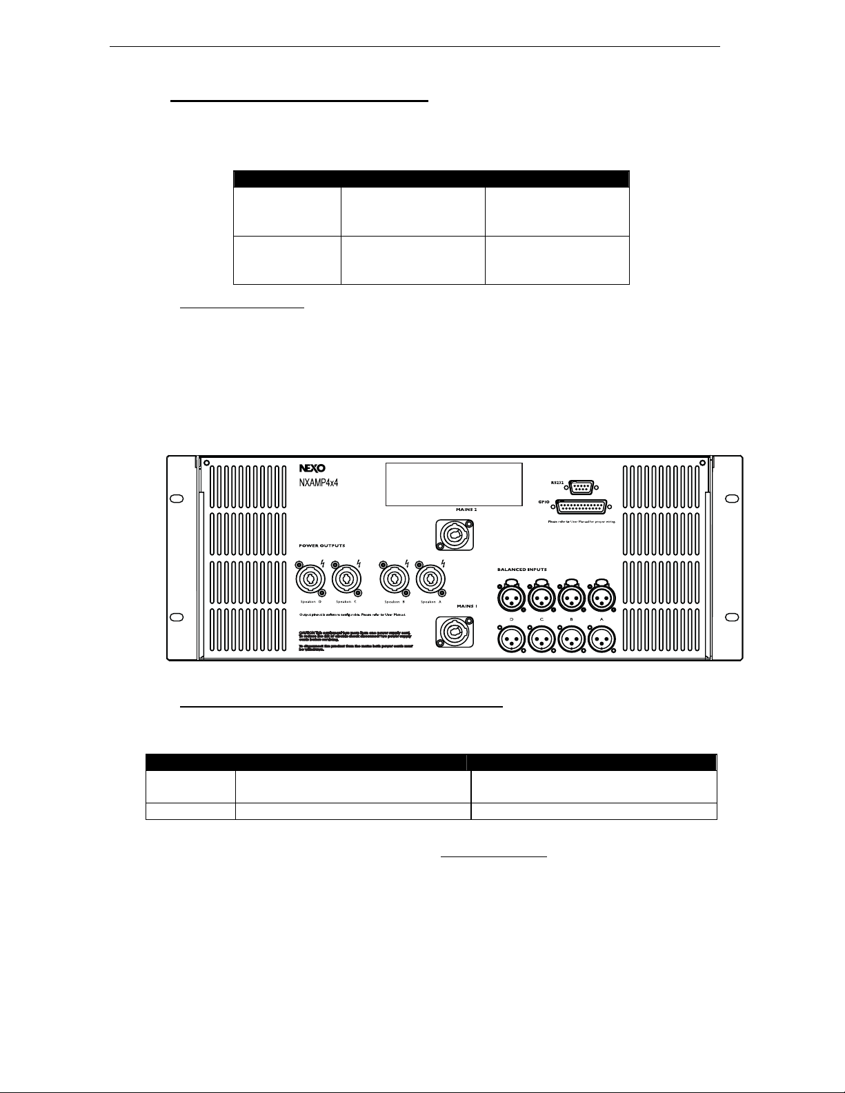
NXAMP4x1 and NXAMP4x4 power capability is listed in the table below:
Mode 4 Channels Bridge Stereo
NXAMP4x1 4 x 650 Watts / 8 Ohms
4 x 900 Watts / 4 Ohms
4 x 1300 Watts / 2 Ohms
NXAMP4x4 4 x 1900 Watts / 8 Ohms
4 x 3400 Watts / 4 Ohms
4 x 4000 Watts / 2 Ohms
2 x 1800 Watts / 8 Ohms
2 x 2600 Watts / 4 Ohms
2 x 6800 Watts / 8 Ohms
2 x 8000 Watts / 4 Ohms
3.2.1 NXAMP connectors
NXAMP4x1 and NXAMP4x4 re ar panels feature:
- 4 analog inputs / outputs (links) on XLR3 connectors;
- 4 digital inputs / outputs on RJ45 connectors with optional card;
- 4 speaker level outputs on NL4FC connectors.
Figure below shows connectors implementation on the rear panel.
3.2.2 45°N-12 and NXAMP recommended configurations
Below table lists basic requirements for proper use of NXAMP TD Controllers in conjunction with 45°N12:
Passive Mode Active Mode
1 or 2 x 45°N-12 1 channel of NXAMP4x1 in Bridge Stereo Mode
1 channel of NXAMP4x4 in 4 channels Mode
3 x 45°N-12 1 channel of NXAMP4x4 in 4 channels Mode 2 channels of NXAMP4x4 in 4 channels Mode
Please refer to following documents (available at www.nexo-sa.com
configurations:
- NXAMP4x1 and NXAMP4x4 User Manual
- NXAMP Application Guideline
- NXAMP Load Setup list
2 channels of NXAMP4x1 in Bridge Stereo Mode
2 channels of NXAMP4x4 in 4 channels Mode
) for detailed information on specific
Page 14
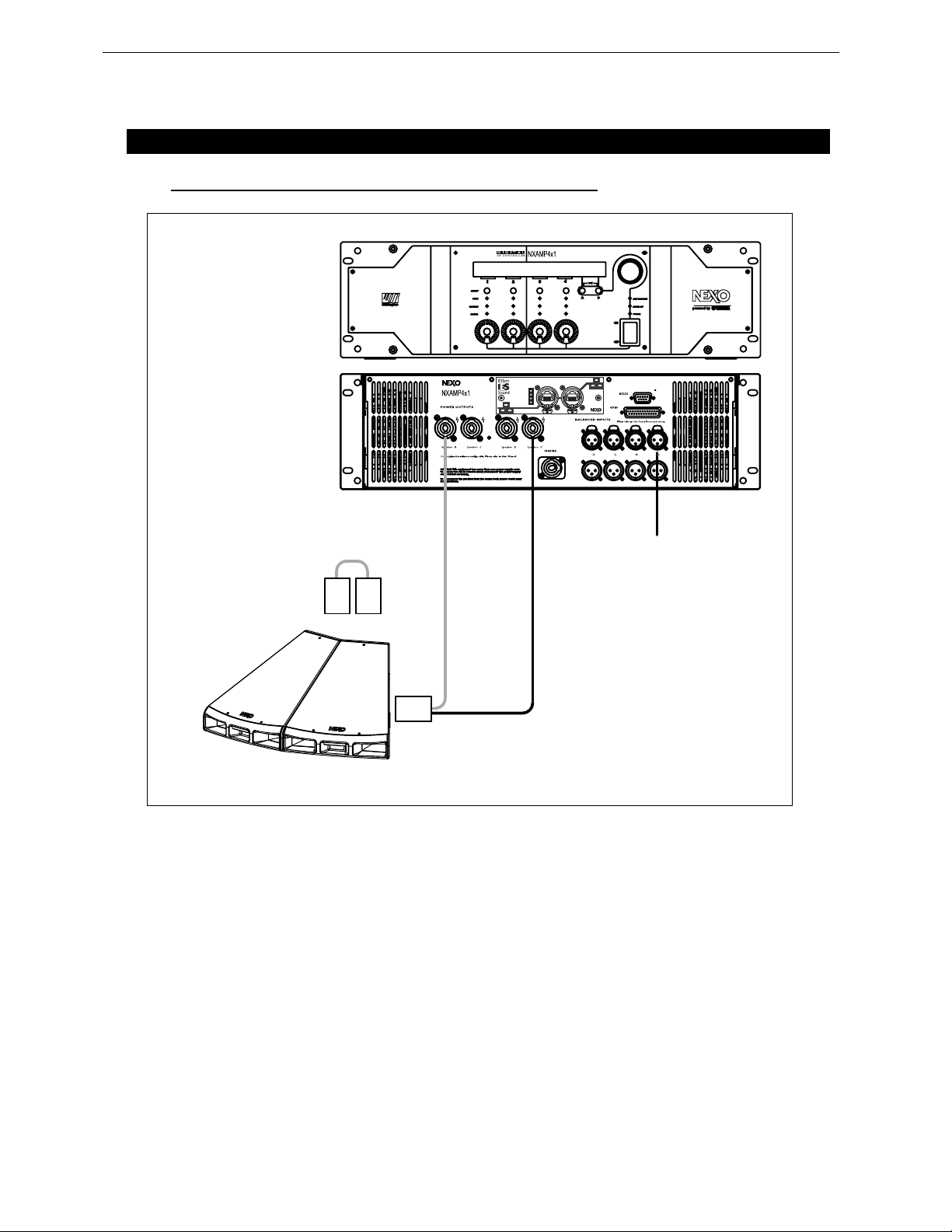
Page 14/26 CONNECTION DIAGRAMS
4 CONNECTION DIAGRAMS
4.1 45°N-12 / NXAMP4x1 - Bridge Stereo – Active mode
NXtension-ES
In Rx
In Tx
Out Rx
Out Tx
OUT D
SP4
SP4
SP4
SP4
SP4
SP4
2+/2-
1+/1-
3 x HF
3 x LF
SP4
Out In
OUT A
IN A
Page 15
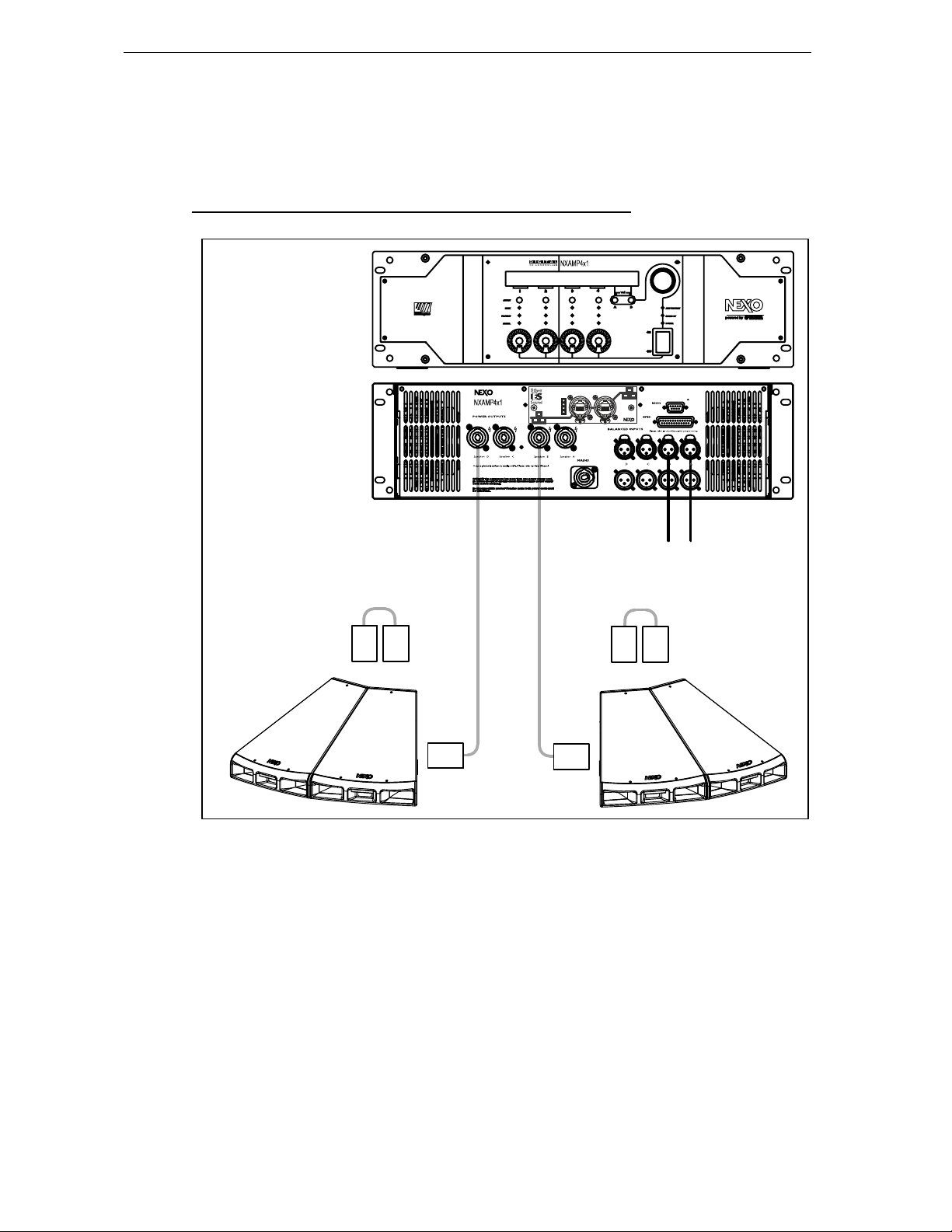
CONNECTION DIA GRAMS Page 15/26
4.2 45°N-12 / NXAMP4x1 - Bridge Stereo – Passive mode
NXtension-ES
In Rx
In Tx
Out Rx
Out Tx
OUT D
BRIDGED MODE
OUT B
BRIDGED MODE
SP4
SP4
2+/2- HF+LF
2+/2- HF+LF
SP4
SP4
Out In
SP4
IN B
SP4
IN A
Page 16
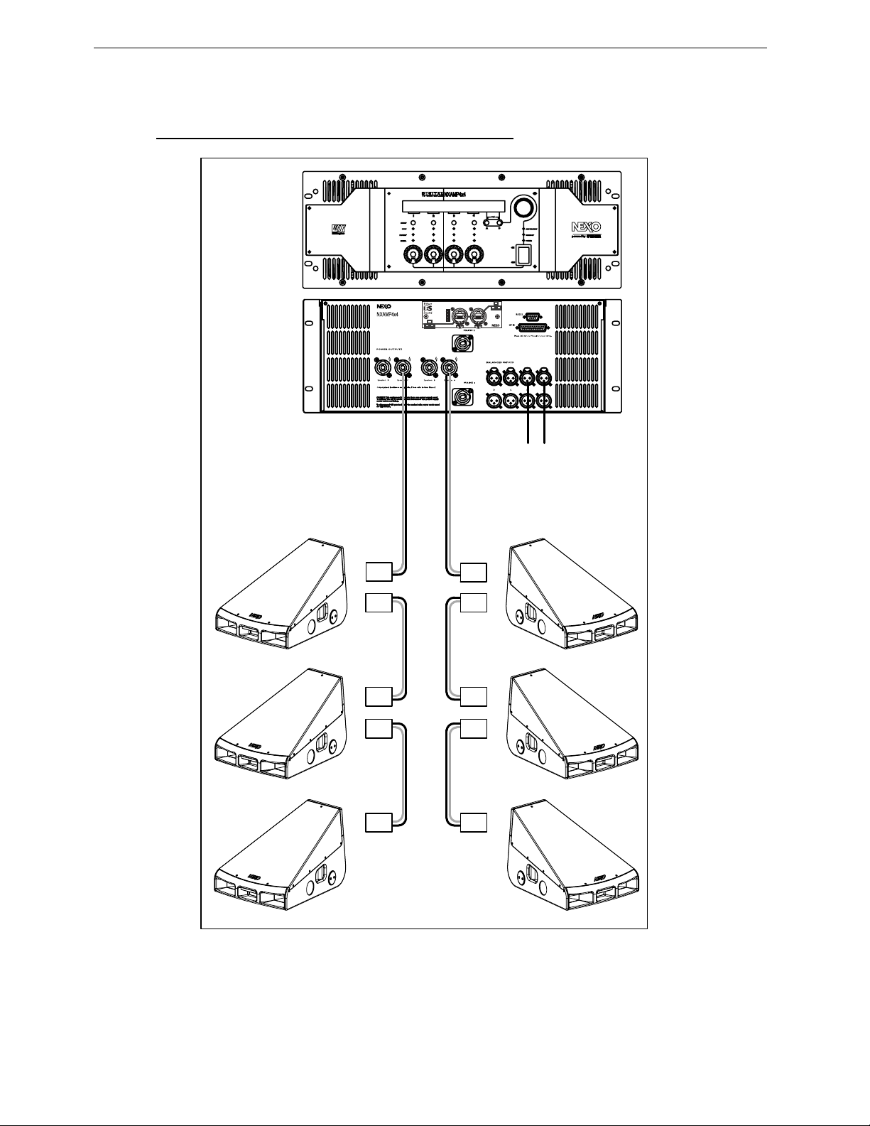
Page 16/26 CONNECTION DIAGRAMS
4.3 45N12 / NXAMP4x4 - 4 Channels – Active Mode
NXtension-ES
In Rx
In Tx
Out Rx
Out Tx
OUT C
OUT A
2+/2- HF
1+/1- LF
SP4
SP4
SP4
SP4
SP4
Out In
2+/2- HF
1+/1- LF
SP4
SP4
SP4
SP4
SP4
IN B
IN A
Page 17
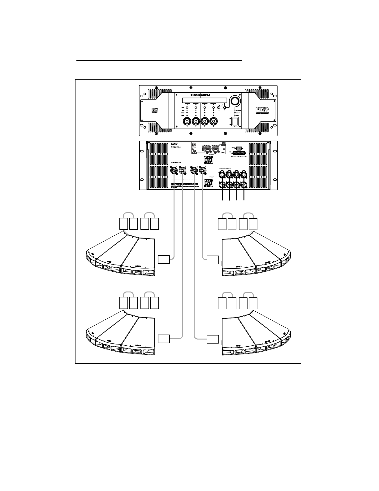
CONNECTION DIA GRAMS Page 17/26
4.4 45°N-12 / NXAMP4x4 - 4 Channels – Passive Mode
NXtension-ES
In Rx
In Tx
Out Rx
Out Tx
Out In
OUT D
OUT A
OUT B
OUT C
SP4
SP4
SP4
SP4
2+/2- HF+LF
2+/2- HF+LF
SP4
SP4
SP4
SP4
SP4
SP4
SP4
SP4
IN D
SP4
SP4
IN C
SP4
SP4
IN B
IN A
SP4
SP4
SP4
SP4
Page 18
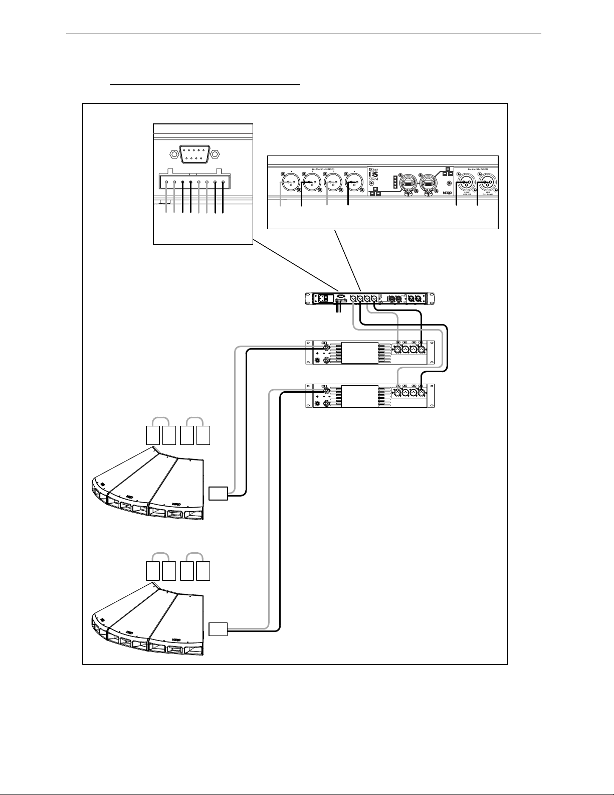
Page 18/26 CONNECTION DIAGRAMS
4.5 45°N-12 / NX242-ES4 – Active Mode
FROM AMPLIFIERS
+ 4 - + 3-
+ 2 - + 1 -
N12 #2
HF
TO AMPLIFIERS
N12 #1
N12 #2
HF
LF
N12 #1
LF
NXtension-ES
In Rx
In Tx
Out Rx
Out Tx
Out In
IN
IN
1
2
N12 #2
LF
N12 #2
HF
N12 #1
HF
N12 #1
LF
NXtension-ES
Out In
In Rx
In Tx
Out Rx
Out Tx
STEREO
AMPLIFIER 1
STEREO
AMPLIFIER 2
SP4
SP4
SP4
SP4
2+/2-
1+/1-
SP4
3 x HF
3 x LF
SP4
SP4
SP4
SP4
2+/2-
1+/1-
SP4
3 x HF
3 x LF
Page 19
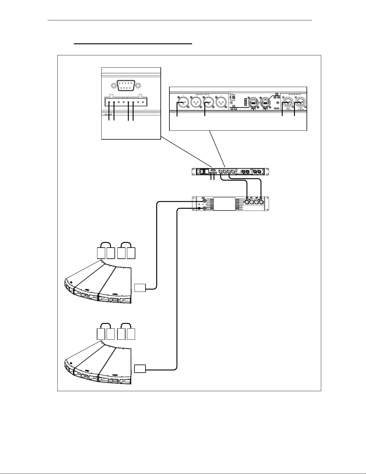
CONNECTION DIA GRAMS Page 19/26
4.6 45°N-12 / NX242-ES4 – Passive Mode
FROM AMPLIFIERS
+ 4 - + 3-
SP4
N12 #2
SP4
+ 2 - + 1 -
SP4
N12 #1
SP4
N12 #2
2+/2- HF+LF
2+/2- HF+LF
TO AMPLIFIERS
N12 #1
AMPLIFIER
STEREO
NXtension-ES
In Rx
In Tx
Out Rx
Out Tx
NXtension-ES
Out In
In Rx
In Tx
Out Rx
Out Tx
Out In
IN
IN
1
2
SP4
SP4
SP4
SP4
SP4
SP4
Page 20
Page 20/26 APPLICATION GUIDELINES
5 APPLICATION GUIDELINES
5.1 SAFETY FIRST
Before proceeding with installation of 45°N-12, please ensure that the components are present and
undamaged. In the event of any shortage, please contact your supplier.
Statistically, many more injuries occur due to unstable ground set systems than those associated with
flown systems. There are several reasons for this fact, however the message is clear:
Always survey the supporting structure upon which 45°N-12 is to be set. Inspect stage support and if
necessary ask for the stage scrims and dressings be removed to allow access.
If the stage surface slopes, as it does in some theatres, ensure that the system is prevented from sliding
forwards due to vibration. This may require the fitting of timber battens to the stage floor.
For outdoor systems ensure that that the system is protected from wind forces which might cause the
monitor system to become unstable. Wind forces can be huge, especially upon large systems, and
should never be underestimated. Observe meteorological forecasts, calculate the “worst case” effect
upon the system prior to erection and ensure that the system is secured appropriately.
Be aware that safety procedures are as important in the truck and in the warehouse as they are at the
venue.
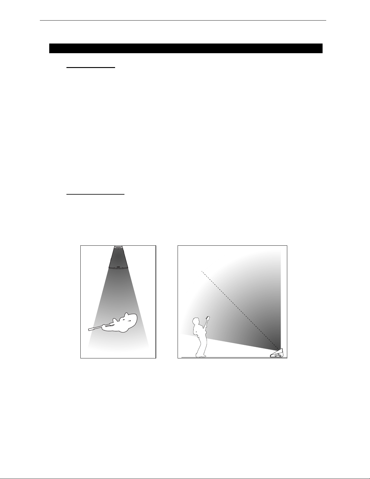
5.2 45°N-12 Coverage
Below figures illustrate 45°N-12 horizontal and vertical coverage behavior.
Main coverage features are:
- 30° horizontal coverage, scalable by 30° steps by arraying units;
- Asymetrical vertical coverage, defined so that frequency response level within +/-3 dB
from 0 to 2 meters.
HORIZONTAL AND VERTICAL COVERAGE
Page 21
APPLICATION GUIDELINES Page 21/26
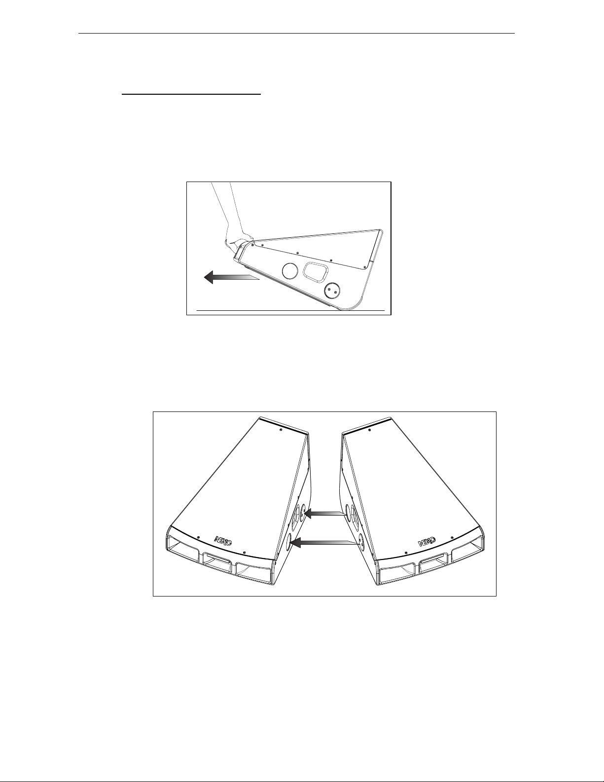
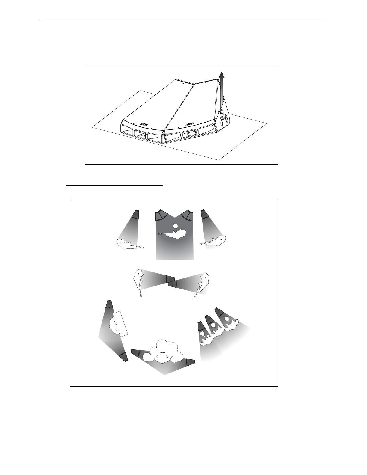
5.3 Handling 45 N-12 on stage
Moving cabinets
In order to move 45°N-12 quickly on stage:
- lift the cabinet from the front handle
- slide it on the ro u n ded rear skids
- drop it at its new position.
Locking cabinets
An integrated magnetic locking system allows connecting multiple monitors together without
requirement for additional parts.
Locking is achieved by simply adjusting cabinets side by side.
Page 22
Page 22/26 APPLICATION GUIDELINES
Unlocking cabinets
To unlock cabinets, simply lift one of the side handles: cabinets will unlock with almost no effort.
5.4 Stage monito r ing applications
Below figures indicate various possible usages for 45°N-12 line monitor.
Page 23

APPLICATION GUIDELINES Page 23/26
5.5 Testing and Maintenance of the system
Cleaning: The exterior of the cabinet can be cleaned with a damp cloth soaked in mild soapy water.
On no account use solvent based cleaners, which may damage the finish of the cabinet.
After cleaning, the 45°N-12 front grid must be treated with a suitable lubricant to prevent rusting.
NEXO recommends the use of Scottoil FS365 which is a water-based lubricant with a mixture of
machine oil, surfactant and anti-rust treatment.
Page 24
Page 24/26 45 N-12 TECHNICAL SPECIFICATIONS
6 45°N-12 TECHNICAL SPECIFICATIONS
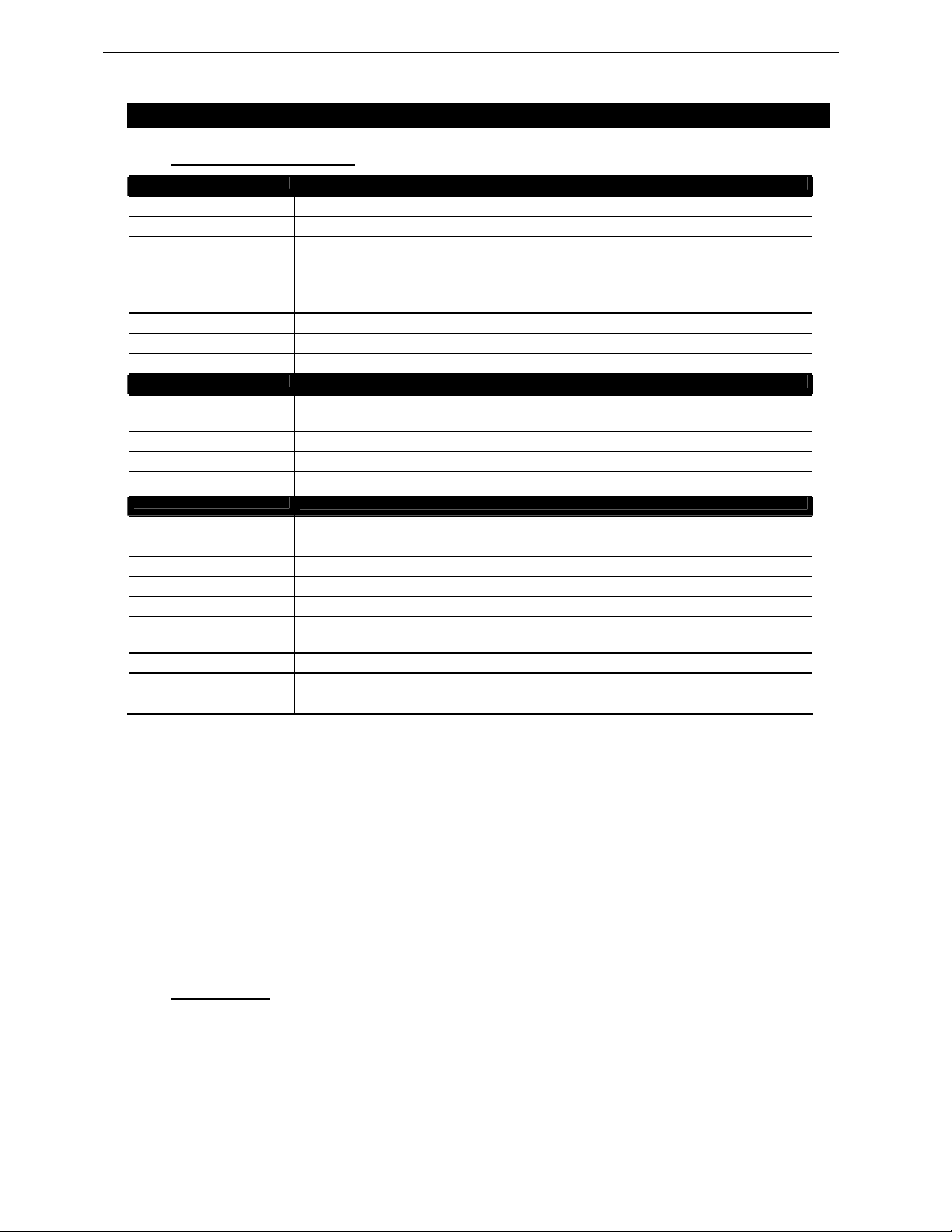
6.1 System specifications
SYSTEM SPECIFICATIONS
Frequency Response [a] 55 Hz - 19 kHz ±3dB
Usable Range @-6dB [a] 50 Hz – 20 kHz
Sensitivity 1W @ 1m [b] 106 dB SPL Nominal - 104 dB SPL Wideband
Nominal Peak SPL @ 1m [b] 1 unit: 137 to 140dB Peak / 2 units: 140 to 143dB Peak
HF Dispersion [c] 30° Horizontal - Scalable 30° steps when arrayed.
Crossover Frequencies LF-HF: 1kHz Active or Passive (internally configurable).
Nominal Impedance
Recommended Amplifiers
SYSTEM OPERATION
Electronic Controller The NEXO TDcontroller’s presets are precisely matched to the 45N Series cabinets and include
Dispersion configuration Internally mounted magnets allow 45°N-12 inter-cabinet locking for coverage / SPL scalability.
Subbass LS600 extends system low frequency response down to 38 Hz.
Speaker Cables Active: 1-/1+:LF; 2-/2+: HF.
PRODUCT FEATURES
Components : LF [VLF]
Height x Width x Depth 392 x 492 x 576 mm (15.43" x 19.37" x 22.67").
Weight : Net 24 kg (53 lbs).
Connectors 2 x NL4MP SPEAKON 4 pole
Construction Main structure: Baltic Birch Ply finished with structured black coating.
Fittings: 4 handles (2 side metal recessed, 2 front and rear moulded).
Front finish Perforated dark grey metal grille.
Lock ing Element s Integrated magnets for mechanical locking.
As part of a policy of continual improvement, NEXO reserves the right to change specifications without notice.
[a] Response curves & data : Half-Space Far Field for the 45°N-12 + NXTD Controller.
[b] Sensitivity & Peak SPL data : these will depend on spectral distribution and crest factor of program material. Measured with band limited Pink Noise.
Nominal refers to Voice Decade (300Hz - 3kHz), Wideband to the specified ±3dB range. Data are for speaker + processor + recommended
amplifier combinations. Peak SPL is at clipping of recommended amplifier.
[c] Directivity curves & data : obtained by computer treatment on off axis response curves.
HF
45N12 with TDcontroller
22.5° Diagonal (Coupling Plane) - Scalable 22.5° steps when arrayed.
60° Vertical (Asymmetrical -45° / +15°).
Active LF 8Ω, HF 16Ω. Passive 8Ω.
Active LF 1000 to 1500 W 8Ω / HF 250 to 500 W 16Ω. Passive 1200 to 2000 W 8Ω.
sophisticated protection. Using 45°N-12 cabinets without a properly connected NEXO TDcontroller
will result in poor sound quality and can damage components.
Passive: 1-/1+: Not Connected; 2-/2+:LF + HF.
LF 1 x 12" (30 cm) high excursion Neodymium 8Ω driver.
HF 1 x 3" voice coil, 1.4" throat Neodymium 16Ω compression driver on a 22.5° hyperboloid
reflective wavesource.
Rear lower and bottom section: Steel with dark grey coating.
Front vents and rear upper section: Injected polyurethane front vents, black coating.
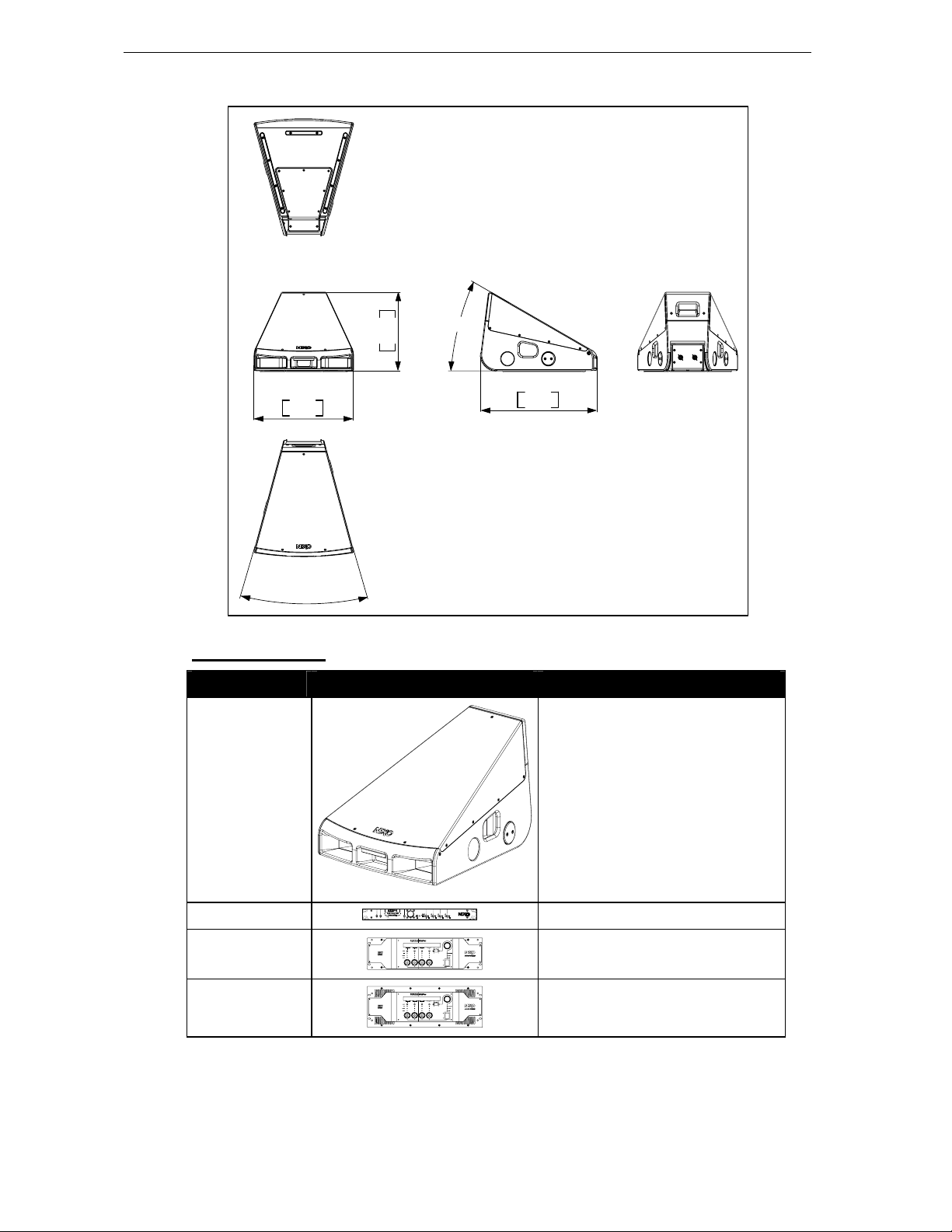
6.2 Dimensions
Page 25
45 N-12 TECHNICAL SPECIFICATIONS Page 25/26
15.43"
392 mm
30°
492 mm
19,37"
576 mm
22,67"
30°
6.3 Component List
MODEL DRAWING DESCRIPTION
45N12
NX 242–ES4
NXAMP4x1
NXAMP4x4
45N12 speaker
Digital TDcontroller
Digital Po wered Controller 4x1300W
Digital Po wered Controller 4x4000W
Page 26

Page 26/26 USER NOTES
7 USER NOTES
France
Nexo S.A.
Parc d’activité de la dame jeanne
F-60128 PLAILLY
Tel: +33 3 44 99 00 70
Fax: +33 3 44 99 00 30
E-mail: [email protected]
www.nexo-sa.com
 Loading...