


GEO S8
GEO S Series
S805 5° Tangent Array Module
S830 30° Tangent Array Module
CD12 HyperCardoid Subbass
User Manual
GEO S8 SERIES USER MANUAL V1.05
Date: 05/10/2010

P.2 PLEASE READ CAREFULLY BEFORE PROCEEDING
GEO is new technology
The 3 year GEO R&D Project has generated the following patent applications:
• The GEO Hyperboloid Reflective Wavesource™ works on a different principle from the
coercive megaphone-variant horns you know and love/hate. If you apply “tried and true”
methods to this entirely different species of waveguide, the results are likely to be very
different from what you expect.
• The Configurable Directivity Device. A waveguide that allows the operator to alter its
behaviour in the field? Yes. Another unprecedented development that’s easy to use – once
you know how and when.
• The Directivity Phase Device needs no operator input to work properly, but it’s always nice
to know…
GEO is not hard to use when you underst and how…
The R&D behind GEO is revolutionary, but it is grounded in years of practical experience with the problems of
delivering high quality sound to large audiences at professional SPL levels. GEO includes a simple yet
powerful and highly predictive design tool – NS-1. The array assembly system is keyed to the design software
and will easily enable you to deploy your design with precision to 0.01°. The NX242 includes presets that have
been tested and measured by NEXO R&D. They cover virtually any GEO tangent array configuration,
horizontal or vertical, with or without the CD12 HyperCardioid Subbass.
GEO is a high precision system
The GEO Wavesource controls acoustic energy more precisely than previous generations of coercive
waveguides based on the megaphone. This precision makes the GEO system more capable tha n previous
array elements. It also makes GEO less forgiving of mistakes in design and deployment. While megaphone-
variant horns never combine into a coherent array, they can deliver acceptable results even if the design and
deployment of the system is less than optimal. This is not the case with GEO.
GEO is a tangent array, not a “line array”
GEO Technology is equally effective in designing and deploying tangent horizontal arrays or c urved vertical
arrays. For best results in a specific application you need to know how multi-speaker arrays interact with
audience geometry, along with the benefits and drawbacks of curved vertical arrays and horizontal arrays.
Curved vertical ta ngent arrays require di fferent design techniqu es
For the past 20 years, sound reinforcement professionals have worked with horizontal arrays that use
megaphone-variant horns to deliver “[more or less] equal power to equal angles.” Curved vert ical arrays are
designed to deliver “equal power to equal areas.” When conventional coercive horns are used in the array
elements, their lack of precision masks errors in the design of the array and in the aiming of the individual
cabinets. The highly precise GEO wavesource responds accurately, consistently and predictably to the design
and deployment of a curved vertical tangent array. T his is why the G EO rigging s ystem is designed t o c ontrol
angular splay to 0.01° accuracy.
GEO curved vertical ta ngent arrays require d ifferent operati onal techniques
Over the years, system designers and operators have developed a number of signal processing techniques to
disguise and partly overcome the limitations of coercive megaphone waveguides. “Frequency shading,”
“amplitude shading,” “system tuning,” all of these are tools of the advanced sound system operator. NONE OF
THESE TECHNIQUES ARE APPLICABLE TO GEO TANGENT ARRAYS. Instead of enhanci ng the array’s
performance they will severely degrade it.
Take a little time to learn how to get great results with GEO Technology. It’s an investment that will pay off in
more satisfied clients, more efficient operating procedures and more recognition for your skill as a sound
system designer and operator

PLEASE READ CAREFULLY BEFORE PROC EEDING P.3
PLEASE READ CAREFULL Y BEFORE PROCEEDING
BASIC PRECAUTIONS
Do not open the speaker system or attempt to disassemble the internal parts or modify them in any
way. The speaker system contains no user-serviceable parts. If it should appear to be malfunctioning
or damaged, discontinue use immediately and have it inspected by qualified NEXO service personnel.
Water exposure: Do not expose the speaker system to direct rain, do not use it near water or in wet
conditions. Do not place containers with liquid on speaker system as they might spill into openings. If
any liquid such as water seeps into the speaker system, have it inspected by qualified NEXO
personnel.
SYSTEM DEPLOYMENT SAFETY RULES
Read User Manual before deployment. Before use of enclosed speaker s ystem, please
ensure that anyone involved in system deployment understands the rig ging – stacking –
pole mounting safety rules as described in the speaker system User Manual. Failure to do
this exposes people to potential injury or death.
Always consult qualified NEXO personnel if the device installation requires construction work and make s ure
to observe the following precautions:
Mounting precautions
- choose mounting hardware and an installation location that can support the weight of the speaker system;
- do not use speaker system handles for suspended installation;
- do not expose speaker system to excessive dust or vibration, or extreme cold or heat to prevent
possibility of component damage;
- do not place the speaker system in an unstable position from which it might fall accidentally;
- if speaker systems uses a stand, ensure that stand specifications are adapted, and that stand height does
not exceed 1.40m/55”; never move the stand while the speaker is in position.
Connection and powering precautions
- remove all connected cables before moving the speaker system;
- turn off AC power of all power amplifier units before connecting the speaker system;
- when turning on the AC power to the audio system, always turn on the power amplifier last; when turning
the AC power off, always turn off the power amplifier first;
- when used in cold conditions, a gradual power ramp up should applied to the system on an 5 mn period
to allow the loudspeaker components to stabilize during the very first minutes of usage.
Inspect the speaker system periodically.
P.4 PLEASE READ CAREFULLY BEFORE PROCEEDING
SAFETY INSTRUCTIONS FOR NEXO TD CONTROLLERS
NEXO ANALOGUE PSTDCONTROLLERS, NX242 DIGITAL CONTROLLER, NXAMP4x1
AND NXAMP4x4 POWERED CONTROLLERS ARE CLASS 1 APPARATUS AND MUST
BE EARTHED.
THE GREEN AND YELLOW WIRE OF THE MAINS CORD MUST ALWAYS BE CONNECTED TO AN
INSTALLATION SAFETY EARTH OR GROUND. THE EARTH IS ESSENTIAL FOR PERSONAL SAFETY
AS WELL AS THE CORRECT OPERATION OF THE SYSTEM, AND IS INTERNALLY CONNECTED TO
ALL EXPOSED METAL SURFACES.
- Read these instructions.
- Keep these instructions.
- Heed all warnings.
- Follow all instructions.
- Do not use this apparatus near water.
- Clean only with dry cloth.
- Do not block any ventilation openings. Install in accordance with the manufacturer’s instructions.
- Do not install near any heat sources such as radiators, heat registers, stoves, or other apparatus
(including amplifiers) that produce heat.
- Do not defeat the safety purpose of the polarized or grounding-type plug. A polarized plug has two blades
with one wider than the other. A grounding type plug has two blades and a third grounding prong. The
wide blade or the third prong are provided for your safety. If the provided plug does not fit into your outlet,
consult an electrician for replacement of the obsolete outlet. (US market)
- Protect the power cord from being walked on or pinched part icularly at plugs, convenience receptacles,
and the point where they exit from the apparatus.
- Only use attachments/accessories specified by the manufacturer.
- Unplug this apparatus during lightning storms or when unused for long periods of time.
- Refer all servicing to qualified service personnel. Servicing is required when the apparatus has been
damaged in any way, such as power-supply cord or plug is damaged, liquid has been spilled or objects
have fallen into the apparatus, the apparatus has been exposed to rain or mois ture, does not operate
normally, or has been dropped.
To avoid electrical shock, do not remove covers.
Dangerous voltages exist inside.
Refer all servicing to qualified personnel only.
WARNING: To reduce the risk of fire or electric shock,
do not expose this apparatus to rain or moisture.
RISK OF ELECTRIC SHOCK
DO NOT OPEN
CAUTION
The lightning flash with arrowhead
symbol, within an equilateral triangle
is intended to alert the user to the
presence of uninsulated “dangerous
voltage” within the product's
enclosure that may be of sufficient
magnitude to constitute a risk of
electric shock to persons.
The exclamation point within an
equilateral triangle is intended to
alert the user to the presence of
important operating and
maintenance (servicing) instructions
in the literature accompanying
the appliance.

PLEASE READ CAREFULLY BEFORE PROC EEDING P.5
HIGH SOUND PRESSURE LEVELS
Exposure to extremely high noise levels may cause permanent hearing loss. Individuals
vary considerably in susceptibility to noise-induced hearing loss but nearly everyone will lose
some hearing if exposed to sufficiently intense noise for a sufficient period of time. The U.S.
Government’s Occupational and Health Administration (OSHA) has specified the following
permissible noise level exposures: Sound Duration Per
Day In Hours Sound Level dBA, Slow Response
8 90
6 92
4 65
3 97
2 100
1 ½ 102
1 105
½ 110
¼ or less 115
According to OSHA, any exposure in excess of the above permissible limits could result in some hearing loss.
Ear plugs or protectors to the ear canals or ov er the ears must be worn when operating this amplification
system in order to prevent permanent hearing loss, if exposure is in excess of the limits as set forth above. To
ensure against potentially dangerous exposure to high sound pressure levels, it is recommended that all
persons exposed to equipment capable of producing high sound pressure levels such as this amplif ication
system be protected by hearing protectors while this unit is in operation.
DISPOSAL OF OLD ELECTRICAL & ELECTRONIC EQUIPMENT
This symbol on the product or on its packaging indicates that it shall not be t reated as
household waste. Instead it shall be handed over to the applicable collection point for the
recycling of electrical and electronic equipment. By ensuring this product is dis posed of
correctly, you will help prevent potential negative consequence for the environment and
human health, which could otherwise be caused by inappropriate waste handling of this
product. The recycling of materials will help to conserve natural resources. For more
detailed information about recycling of this product, please contact your local city office,
your household waste disposal service or the shop where you purchased the product.

P.6 TABLE OF CONTENTS
T ABLE OF CONTENTS
PLEASE
READ CAREFULLY BEFORE PROCEEDING................................................................................. 3
TABLE
OF CONTENTS.....................................................................................................................................6
I
NTRODUCTION..................................................................................................................................................... 7
G
ENERAL SET-UP INSTRUCTIONS......................................................................................................................... 8
Speaker Wiring ...............................................................................................................................................8
Amplifier Selection.......................................................................................................................................... 9
NX242
DIGITAL TDCONTROLLER SETTINGS.......................................................................................................11
GEO Vertical Arrays .....................................................................................................................................11
GEO Horizontal Tangent Arrays ..................................................................................................................12
Speaker Quantity..........................................................................................................................................12
Delays & System Alignment.........................................................................................................................13
Initial Set-up Precautions..............................................................................................................................13
D
EPLOYING GEO TANGENT ARRAYS................................................................................................................. 14
Vertical vs. Horizontal...................................................................................................................................14
CD12 HyperCardioid Subbass..................................................................................................................... 14
NS-1
SIMULATION SOFTWARE............................................................................................................................15
U
SING THE CONFIGURABLE DIRECTIVITY DEVICE...............................................................................................16
Installing & removing GEO’s Configurable Directivity flanges.....................................................................16
When & where to use Configurable Directivity flanges ...............................................................................17
GEO
APPLICATION GUIDELINES......................................................................................................................... 18
GEO
TANGEN T ARRAY RIGGING SYSTEM..........................................................................................................19
SAFETY FIRST ............................................................................................................................................19
GEO Loudspeakers......................................................................................................................................21
Angle-setting bar........................................................................................................................................... 22
Assembling a curved vertical GEO array..................................................................................................... 22
CD12 BUMPER............................................................................................................................................24
Combination GEO/CD12 bumper................................................................................................................25
Assembling Horizontal GEO Arrays.............................................................................................................26
Ground stacking Geo Array..........................................................................................................................26
Dimensions & Weights ................................................................................................................................. 27
T
ECHNICAL SPECIFICATIONS.............................................................................................................................. 28
GEO S805.....................................................................................................................................................28
GEO S830.....................................................................................................................................................30
GEO CD12.................................................................................................................................................... 32
U
SER’S NOTES...................................................................................................................................................34

INTRODUCTION P.7
INTRODUCTION
Thank you for selecting NEXO GEO S8 Series products. This manual is intended to provide you with
necessary and useful information about your GEO System, which includes the following products:
• S805 5° Tangent Array Module. 8” (20cm) Neodymium Hi-flux 16 Ohm LF Driver and 1”
Throat Neodymium HF Driver on a 5° Hyperboloid Reflective Wavesource. Your main
building block for curved vertical tangent arrays; integral precision array assembly syst em.
• S830 30° Tangent Array Module. 8” (20cm) Neodymium Hi-flux 16 Ohm LF Driver a nd 1”
Throat Neodymium HF Driver on a 30° Hyperboloid Reflective Wavesource. The building
block for horizontal tangent arrays, and the tangent down-fill element for curved vertical
arrays; integral precision array assembly system.
• CD12 HyperCardoid Subbass. Two 12” (30cm) Long Excursion Neodymium 6 Ohm Drivers,
each controlled by one DSP channel, creating a 120° x 120° hypercardioid pattern. Can be
flown or ground-stacked.
• NX242 Digital TDcontroller. Provides comprehensive control of the above GEO S8 Series
loudspeakers in multiple configurations. For a complete description of this unit, please refer
to the NX242 User Manual. Please remember that the NX242 Digital TDcontroller’s DSP
algorithms and parameters are software and are updated regularly. Please consult the
NEXO web site (www.nexo.fr
or www.nexo-sa.com) for the latest software releases.
• GEO Flying System. Coupled with the integral array assembly system on GEO S8 Series
cabinets, provides safe, flexible and simple means of flying GEO Tangent Arrays. NOTE:
GEO Tangent Arrays control the dispersion of acoustic energy with a high degree of
precision. Inclinometers and laser aiming devices are essential to ensure proper audience
coverage when hanging or flying a GEO Tangent Array.
• NS-1 Design Software. MATLAB based Windows software simplifies the design and
implementation of vertical tangent G EO arrays.
Please devote some attention to reading this manual. A comprehensive understanding of GEO
waveguide theory, tangent arrays, and specific features of the GEO S8 Series will help you to operate
your system at its full potential.

P.8 GENERAL SET-UP INSTRUCTIONS
GENERAL SET-UP INSTRUCTIONS
Speaker Wiring
The loudspeakers are connected to power amplifiers via
NL4FC SPEAKON connectors (not supplied). A wiring
diagram is printed on the connection panel located on the
back of each cabinet. The in/out pins of the SPEAKON
sockets are identified. The sockets are connected in
parallel within the enclosures (see the Connections
Diagrams section of this manual). Either connector can
be used to connect power amplifiers or to power an
additional GEO Tangent Array Module (NEXO
recommend a maximum of six S Series Tangent Array
Modules per amplifier channel).
NB: The front loudspeaker of the CD12 is wired 2+ & 2-
while the rear loudspeaker is wired 1- & 1+. NEVER
connect the CD12 to the GEO S805/S830.
Cable choice consists mainly of selecting cables of the
correct sectional dimension (size) in relation to the load
resistance and the cable length. Too small a cable
section will increase both its serial resistance and its
capacitance; this reduces the electrical power delivered to
the loudspeaker and can also induce response (damping factor) variations.
For a serial resistance less or equal to 4% of the load impedance (damping factor = 25), t he maximum cable
length is given by:
L
max
= Z x S S in mm
2
, Z in Ohms, L
max
in meters
The table below indicates these values, for 3 common sizes.
Load Impedance (Ω)
2 3 4 6 8 12 16
Cable section Maximum Length (meters)
1,5 mm² (AWG #14) 3 4.5 6 9 12 18 24
2,5 mm² (AWG #12) 5 7.5 10 15 20 30 40
4 mm² (AWG #10) 8 12 16 24 32 48 64
Examples :
The GEO S805 and S830 have a nominal impedance of 16 ohms, so a 6x GEO S8 cluster wired in parallel
will present a 16/6 = 2.7 Ohms load impedance. The maximum acceptable 2x2.5 mm
2
(AWG #12) cable
length L
max
for such a cluster is 6.75 meters.
The CD12 subwoofer has a nominal impedance of 2 x 6 Ohms, therefore 2 CD12s wired in parallel will
present a 2 x 3 Ohms load impedance. The maximum acceptable 4x4 mm
2
(AWG #10) cable length L
max
is
then 12 meters.
IMPORTANT NOTE: Long speaker cables induce capacitive effects – up to hundreds of pF depending on the
quality of the cable, with a low-pass effect in high frequencies. If long s peaker cables must be used, ensure
that they do not remain coiled while in use.

GENERAL SET-UP INSTRUCTIONS P.9
Amplifier Selection
Power
GEO S8 Series array elements are rated for 500 Watts power handling. Although each array element has a
16 Ohm nominal impedance, NEXO recommends that you connect no more than six S8 Series array
elements to a single amplifier channel. The amplifiers used for this application should be capable of delivering
1500 to 3000 Watts into a low impedance (typically specified as 2 Ohm) load. Budget constraints are the only
reason to select lower output power amplifiers. A lower power amplifier will not reduce the chances of driver
damage due to overexcursion, and may actually increase the risk of thermal damage due to sustained
clipping.
The CD12 requires two amplifier channels delivering separately processed signals to produce its
hypercardioid pattern. The amplifier model should be the same as that used for the GEO S8 Series array
elements. Two CD12s can be connected in parallel: take care that both front woofers and both rear woofers
are connected in parallel.
Current rating
It is very important that the amplifier behaves correctly under low load conditions. A speaker system is reactive
by nature: on transient signals like music it will require four to ten times more instantaneous current than its
nominal impedance would indicate. Amplifiers are generally specified by continuo us RMS power into resistive
loads, however the only useful information about current capacity is the specif ication into a 2 Ohm load. It is
possible to perform an amplifier listening test by loading the amps with twice the number of cabinets
considered for the application (2 speakers per channel instead of one, 4 inst ead of 2) and running the amps
up to the onset of clipping. If the signal does not noticeably deteriorate, the amplifier is well adapted
(overheating after approximately ten minutes is normal but thermal protection must not operate too quickly
after starting this test).
Amplifier gain settings
Technical knowledge of the amplifiers to be used with the system is essential. This data is the key to the
correct alignment of the system. It is especially important to know the gain of all amplifiers used in your set-up.
The tolerance should be about ±0.5 dB. In practice this can be difficult to achieve because:
• Some amplifier brands have an identical input sensitivity for models of different power rating
(this infers a different voltage gain for each model). For example, a range of amplifiers with
different power outputs, all having a published input sensitivity of 775mV/0dBm or
1.55V/+6dBm, will have a wide range of actual gains – the higher the power, the greater the
gain.
• Various other brands may offer constant gain but only within a given product range, for
example they may fit fixed input sensitivity only on their semi-professional amps.
• Even if a manufacturer applies the constant gain rule to all models, the value selected will
not necessarily be the same as that chosen by other manufacturers.
• Some products can exhibit manufacturing tolerances for the same model of ±1dB or more.
Some amplifiers may have been modified, possibly without any label indicating the new
values. Others may have gain switches fitted internally where it is impossible for the user to
verify the actual setting without opening the amplifier casing. In cases where you don't know
the gain of your amplifier (or want to check it) please follow this procedure:
Unplug any loudspeakers from the amplifier outputs
With a signal generator, feed a sine wave at 1000Hz at a known voltage (say 0.5V) to the
input of the amplifier under test
Measure the voltage at the output of the amplifier
Calculate the gain using the formula Gain = 20 * LOG10(Vout/Vin).
P.10 GENERAL SET-UP INSTRUCTIONS
Some examples:
Gain
Vin
20dB 26dB 32dB 37dB (1.4V sensitivity / 1350Wrms)
0.1V 1V 2V 4V 7.1V
0.5V 5V 10V 20V 35.4V
1V 10V 20V 40V 70.8V
Remember that constant sensitivity settings will give a different gain value when the amplifier power is
different.
Gain value
NEXO recommends low gain amplifiers: +26dB is recommended, as it is at the same time adequately low and
quite common amongst amplifier manufacturers. This gain setting improves signal to noise ratio and allows all
preceding electronic equipment, including the NX242 TDcontroller, to operate at optimum level. Remember
that using a high gain amplifier will raise the noise floor proportionally.
Advanced protection
Some high-end amplifiers may include signal processing functions similar to those found in the NX242
TDcontroller ("loudspeaker offset integration", "limiter", "compressor," etc.). These functions are not adapted to
specific system requirements and may interfere with the complex protection algorithms used in the NX242.
NEXO do not advise using other protection systems in conjunction with the NX242 and they should be
disabled.
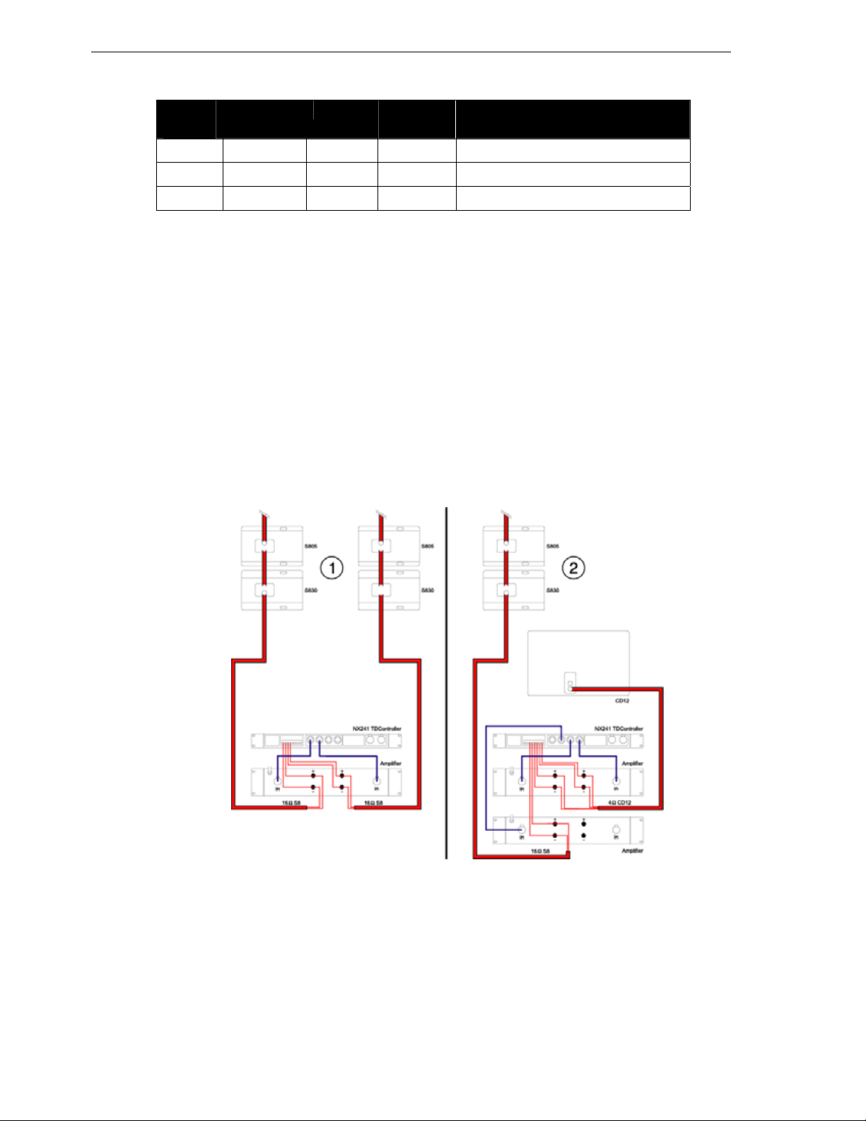
Connection Diagrams
The NX242 TDcontroller provides two basic modes of operation wit h GEO S8 Series products, as shown
below.
1) Stereo GEO S8 with no CD12 sub,
2) Mono GEO S8 with CD12 Sub.
NX242 DIGITAL TDCONTROLLER SETTINGS P.11
NX242 DIGITAL TDCONTR OLLER SETTINGS
The GEO S8 Series cabinets will not perform correctly without the NX242 TDcontroller. Sound quality and
reliability are totally dependent on the correct use of the NX242 TDcontroller, in accordance with the
instructions provided in this manual and in the NX242 User Manual.
All manuals & associated technical notes must be read before set-up. Please contact your NEXO agent for
any literature you may need. The NX242 Digital TDcontroller is able to drive the entire current NEXO range
(GEO, PS & Alpha series, CD12 subs). The following GEO set-ups are examples, for a complete and updated
list please refer to the documentation describing the NX-LOAD.
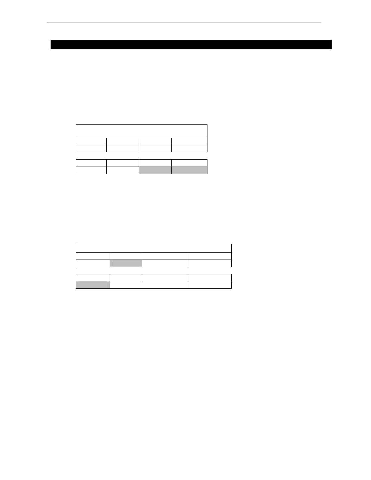
GEO Vertical Arrays
Input/Output Assignments:
GEO S8 Series Wideband Configurations (No Sub)
Input A Input B
Left Right
Output 4 HF Output 3 HF Output 2 LF Output 1 Sub
Left Right No Signal No Signal
S805 4-8 boxes No Sub
Stereo Setup. Input A (Left) & B (right). Output 3 (left) and 4 (right). No signal on output 1 &2.
Configure GEO S805 Wideband for 4-8 boxes.
S805 9-16 boxes No Sub
Stereo Setup. Input A (Left) & B (right). Output 3 (left) and 4 (right). No signal on output 1 &2.
Configure GEO S805 Wideband for 9-12 boxes.
Input/Output Assignments: GEO S8 + CD12 Configurations
Input A Input B
Mono No Signal
Output 4 HF Output 3 HF Output 2 LF Output 1 Sub
No Signal GEO S8 CD12 Front Driver CD12 Back Driver
S805 4-8 boxes CD12 Ground
Mono Setup. Input A. Output 1 (back driver of the CD12), Output 2 (front driver of the CD12), Output 3 (GEO),
no signal on Output 4.
Configure GEO S805 (4-8 boxes) with CD12.
S805 9-6 boxes CD12 Ground
Mono Setup. Input A. Output 1 (back driver of the CD12), Output 2 (front driver of the CD12), Output 3 (GEO),
no signal on Output 4.
Configure GEO S805 (9-16 boxes) with CD12.
S805 4-8 boxes CD12 Flown
Mono Setup. Input A. Output 1 (back driver of the CD12), Output 2 (front driver of the CD12), Output 3 (GEO),
no signal on Output 4.
Configure GEO S805 (4-8 boxes) with CD12 flown.
 Loading...