

Page 1

GEO D Series
D10 10° Tangent Array Module
Geo Sub Directional Sub-bass
User Manual
GEO D Series User Manual V1.06
Date: 05/10/2010
Page 2

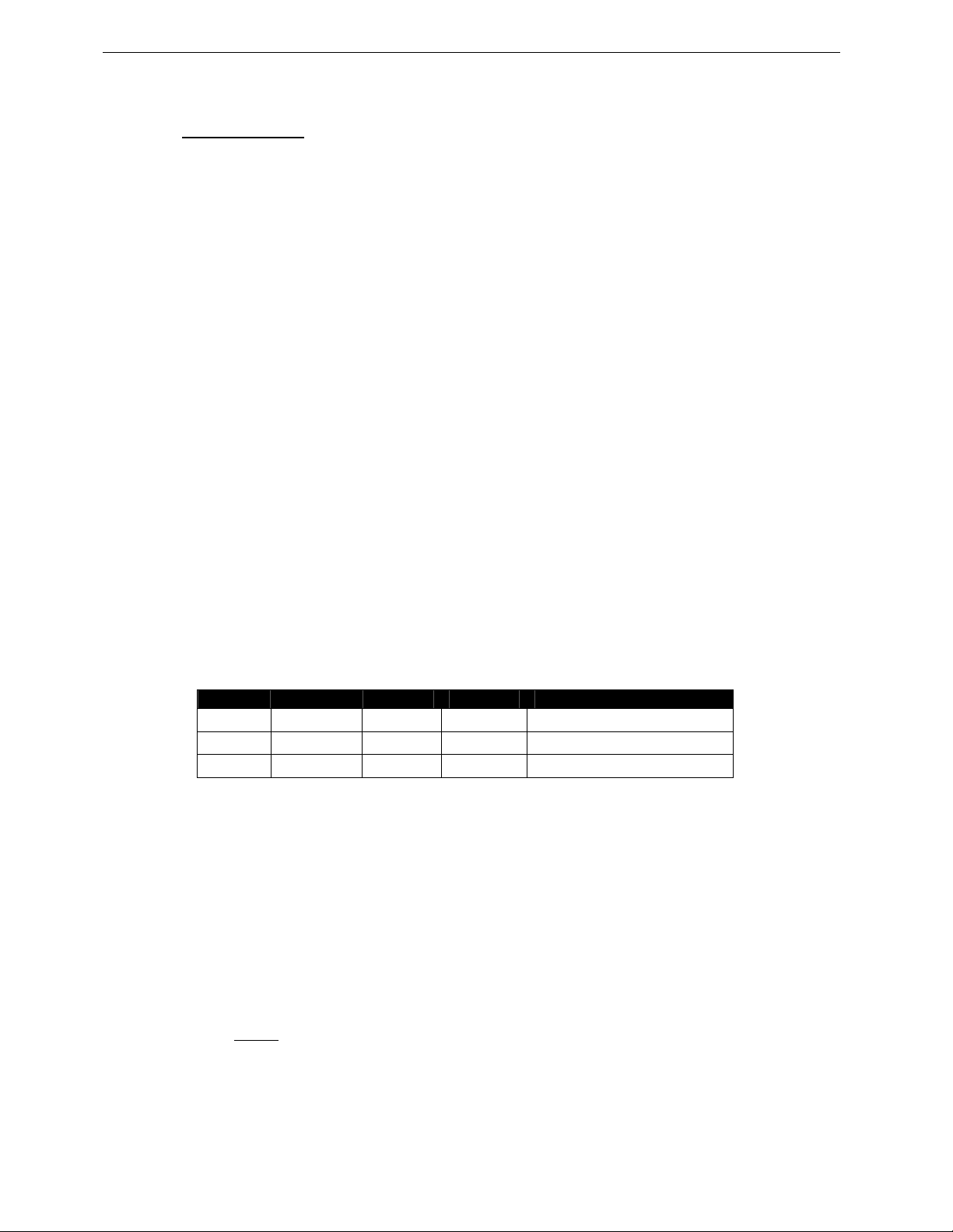
Page 2/97 PLEASE READ CAREFULLY BEFORE PROCEEDING
GEO Technology is radically new thinking
The GEO R&D Project has, to date, resulted in the following patent applications:
• The GEO Hyperboloid Reflective Wavesource™ differs radically from the megaphone-variant
type horns you know and love (or hate). “Tried and true” methods will produce entirely
unexpected results. HRW technology produces precise and predictable results.
• The Configurable Directivity Flange. A waveguide that allows the operator to alter its behaviour.
An unprecedented NEXO development that is easy to use – once you know how and when.
• The Directivity Phase Device needs no operator input to function, but it is reassuring to know that
the coupling of the midrange of the system is considered as important as the high frequencies…
• GEO’s DSP-driven Cardioid Dipolar Sub-bass devices are a new approach to controlling LF/VLF
acoustic energy.
GEO is not hard to use when you understand how…
The technology behind GEO is revolutionary, but it is grounded in years of practical experience with the
problems of delivering high quality professional sound to large audiences at high SPL levels. The GEO
toolbox includes GEOSoft -a simple yet powerful and highly predictive design tool. The array assembly
system is keyed to the design software and will easily enable you to deploy your design with great
precision. The NX 242 Di gita l TDc ontrol ler p rovi des dr iver p rot ecti on and s yste m opti miza tion as wel l as
DSP-driven cardioid pattern control for the GEO D10 Tangent Array Module and the GEO SUB Cardioid
Dipole Sub-bass.
GEO is a high precision system
The GEO HRW™ controls acoustic energy more precisely than other multiple element waveguides. It
also makes GEO less forgiving of mistakes. Whilst conventional horns never combine into a coherent
array, they may deliver acceptable results even if the design and deployment of the system is less than
optimal. This is not the case with GEO where careless installation produces catastrophic results.
A GEO Tangent Array is no t a “line array”
GEO Technology is equally effective in designing and deploying tangent horizontal arrays or curved
vertical arrays. For best results in a specific application the user needs to know how multi-speaker
arrays interact with audience geometry, along with the benefits and drawbacks of curved vertical arrays
and horizontal arrays.
Curved vertical ta ngent arrays requir e different design techni ques
For the past 20 years, sound reinforcement professionals have worked with horizontal arrays that use
conventional horns to deliver [more or less] ‘equal power to equal angles’. Curved vertical arrays are
designed to deliver [more or less] equal power to equal areas’. When arrays use conventional horns ,
the lack of precision, overlap and interference masks errors in array design and aiming. The highly
precise GEO wavesource responds accurately, consistently and predictably to the design and
deployment of a curved vertical tangent array. This is why the GEO rigging system is designed to
control angular splay to 0.01° precision.
GEO curved vertical ta ngent arrays require d ifferent operati onal techniques
Over the years, system designers and operators have developed a number of signal processing
techniques to disguise and partly overcome the limitations of horn design. “Frequency shading,”
“amplitude shading,” “system tuning,” all of these are tools of the advanced sound system operator.
NONE OF THESE TECHNIQUES ARE APPLICABLE TO GEO TANGENT ARRAYS. Instead of
enhancing the array’s performance they will severely degrade it.
Take time to learn how to get great results with GEO Technology. It is an investment that will pay off in
more satisfied clients, more efficient operating procedures and more recognition for your skill as a
sound system designer and operator. A comprehensive understanding of GEO t heory, tangent arrays,
and specific features of the GEO D Series will help you to operate your system at its full potential.
Page 3
PLEASE READ CAREFULLY BEFORE PROCEEDING Page 3/97
PLEASE READ CAREFULLY BEFORE PROCEEDING
BASIC PRECAUTIONS
Do not open the speaker system or attempt to disassemble the internal parts or modify them in any
way. The speaker system contains no user-serviceable parts. If it should appear to be malfunctioning
or damaged, discontinue use immediately and have it inspected by qualified NEXO service personnel.
Water exposure: Do not expose the speaker s ystem to direct rain, do not use it near water or in wet
conditions. Do not place containers with liquid on speaker system as they might spill into openings. If
any liquid such as water seeps into the speaker system, have it inspected by qualified NEXO
personnel.
SYSTEM DEPLOYMENT SAFETY RULES
Read User Manual before deployment. Before use of enclosed speaker system,
please ensure that anyone involved in system deployment understands the rigging –
stacking – pole mounting safety rules as described in the speaker system User Manual.
Failure to do this exposes people to potential injury or death.
Always consult qualified NEXO personnel if the device installation requires construction work and make
sure to observe the following precautions:
Mounting precautions
- c hoose mounting hardware and an installation location that can support the weight of the speaker
system;
- do not use speaker system handles for suspended installation;
- do not expose speaker system to excessive dust or vibration, or extreme cold or h eat to prevent
possibility of component damage;
- do not place the speaker system in an unstable position from which it might fall accidentally;
- if speaker systems uses a stand, ensure that stand specifications are adapted, and that stand
height does not exceed 1.40m/55”; never move the stand while the speaker is in position.
Connection and powering precautions
- remove all connected cables before moving the speaker system;
- turn off AC power of all power amplifier units before connecting the speaker system;
- when turning on the AC power to the audio system, always turn on the power amplifier last; when
turning the AC power off, always turn off the power amplifier first;
- when used in cold conditions, a gradual power ramp up should applied to the system on an 5 mn
period to allow the loudspeaker components to stabilize during the very first minutes of usage.
Inspect the speaker system periodically.
Page 4
Page 4/97 PLEASE READ CAREFULLY BEFORE PROCEEDING
SAFETY INSTRUCTIONS FOR NEXO TD CONTROLLERS
NEXO ANALOGUE PSTDCONTROLLERS, NX242 DIGITAL CONTROLLER,
NXAMP4x1 AND NXAMP4x4 POWERED CONTROLLERS ARE CLASS 1
APPARATUS AND MUST BE EARTHED.
THE GREEN AND YELLOW WIRE OF THE MAINS CORD MUST ALWAYS BE CONNECTED TO AN
INSTALLATION SAFETY EARTH OR GROUND. THE EARTH IS ESSENTIAL FOR PERSONAL
SAFETY AS WELL AS THE CORRECT OPERATION OF THE SYSTEM, AND IS INTERNALLY
CONNECTED TO ALL EXPOSED METAL SURFACES.
- Read these instructions.
- Keep these instructions.
- Heed all warnings.
- Follow all instructions.
- Do not use this apparatus near water.
- Clean only with dry cloth.
- Do not block any ventilation openings. Install in accordance with the manufacturer’s instructions.
- Do not install near any heat sources such as radiators, heat registers, stoves, or other apparatus
(including amplifiers) that produce heat.
- Do not defeat the s afety purpose of the polarized or grounding-type plug. A polarized plug has two
blades with one wider than the other. A grounding type plug has two blades and a third grounding
prong. The wide blade or the third prong are provided for your safety. If the provided plug does not
fit into your outlet, consult an electrician for replacement of the obsolete outlet. (US market)
- Protect the power cord from being walked on or pinched particularly at plugs, convenience
receptacles, and the point where they exit from the apparatus.
- Only use attachments/accessories specified by the manufacturer.
- Unplug this apparatus during lightning storms or when unused for long periods of time.
- Refer all servicing to qualified service personnel. Servicing is required when the apparatus has
been damaged in any way, such as power-supply cord or plug is damaged, liquid has b een spilled
or objects have fallen into the apparatus, the apparatus has been exposed to rain or moisture, does
not operate normally, or has been dropped.
The lightning flash with arrowhead
symbol, within an equilateral triangle
is intended to alert the user to the
presence of uninsulated “dangerous
voltage” within the product's
enclosure that may be of sufficient
magnitude to constitute a risk of
electric shock to persons.
CAUTION
RISK OF ELECTRIC SHOCK
DO NOT OPEN
WARNING: To reduce the risk of fire or electric shock,
do not expose this apparatus to rain or moisture.
To avoid electrical shock, do not remove covers.
Dangerous voltages exist inside.
Refer all servicing to qualified personnel only.
The exclamation point within an
equilateral triangle is intended to
alert the user to the presence of
important operating and
maintenance (servicing) instructions
in the literature accompanying
the appliance.
Page 5

PLEASE READ CAREFULLY BEFORE PROCEEDING Page 5/97
HIGH SOUND PRESSURE LEVELS
Exposure to extremely high noise levels may cause permanent hearing loss.
Individuals vary considerably in susceptibility to noise-induced hearing loss but nearly
everyone will lose some hearing if exposed to sufficiently intense noise for a sufficient
period of time. The U.S. Government’s Occupational and Health Administration (OSHA)
has specified the following permissible noise level exposures: Sound Duration Per
Day In Hours Sound Level dBA, Slow Response
8 90
6 92
4 65
3 97
2 100
1 ½ 102
1 105
½ 110
¼ or less 115
According to OSHA, any exposure in excess of the above permissible limits could result in some
hearing loss. Ear plugs or protectors to the ear canals or over the ears must be worn when operating
this amplification system in order to prevent permanent hearing loss, if exposure is in excess of the
limits as set forth above. To ensure against potentially dangerous exposure to high sound pressure
levels, it is recommended that all persons exposed to equipment capable of producing high sound
pressure levels such as this amplification system be protected by hearing protectors while this unit is in
operation.
DISPOSAL OF OLD ELECTRICAL & ELECTRONIC EQUIPMENT
This symbol on the product or on its packaging indicates that it shall not be treated
as household waste. Instead it shall be handed over to the applicable collection
point for the recycling of electrical and electronic equipment. By ensuring this
product is disposed of correctly, you will help prevent potential negative
consequence for the environment and human health, which could otherwise be
caused by inappropriate waste handling of this product. The recycling of materials
will help to conserve natural resources. For more detailed information about
recycling of this product, please contact your local city office, your household waste
disposal service or the shop where you purchased the product.
Page 6

Page 6/97 CONTENTS
CONTENTS
PLEASE READ CAREFULLY BEFORE PROCEEDING ............................................ ............ 3
CONTENTS............................................................................................................................... 6
1 Introduction...................................................................................................................... 8
2 GEO D General Set-up Instructions............................................................................. 10
2.1 Speaker Wiring .................................................... .... ........ .... .... ....... .... .... ........ .... .... ..10
2.2 Amplifier Selection............................................... ........ .... .... ........ ... .... ........ .... ........ ..12
3 NS-1 Simulation software.............................................................................................. 16
4 Configurable Directivity Device............................................... .... .... ... .... .... .... .... ........ .. 17
4.1 Installing & removing GEO’s Configurable Directivity flanges ................................. 17
4.2 When & where to use Configurable Directivity flanges ............................................18
5 GEO D rigging procedure............................. ................................................................. 19
5.1 SAFETY FIRST ........................................................................................................ 19
5.2 General Description................................................. .... ........ .... .... ....... .... .... ........ .... ..22
5.3 GEO D – GEO SUB Ground Stacked ...................................................................... 27
5.4 GEO D Cluster Flying Setup (1 motor)........................................... .... .... .... .... .... .... ..32
5.5 GEO D Cluster Flying Setup (2 motors)................................................................... 41
5.6 GEO SUB – GEO D Combined Cluster Flying Setup (2 motors required)............... 49
5.7 GEO SUB Cluster Flying Setup (2 motors required)................................................ 58
5.8 Fixed installations..................................................................................................... 65
5.9 Testing and Maintenance of the system...................................................................66
6 NEXO NX242 Digital Controller for GEO D and GEO SUB......................................... 67
6.1 NX242 Proprietary Functions ............................................................................. .... ..67
6.2 Cardioid LF and VLF................................................................................... ........ .... ..69
6.3 GEO D NX242 Setups description .......................... .... .... ....... .... .... ........ .... ........ .... ..69
6.4 Trouble shooting.............................................................. .... ....... .... .... ........ .... .... ......70
Page 7

CONTENTS Page 7/97
7 System alignment guidelines...................................................... ..................................72
7.1 GEO SUB – GEO D Cluster design..........................................................................72
7.2 Stacked GEO SUB’s and Flown GEO D’s ................................................................72
7.3 Flown or Stacked combined GEO SUB’s and GEO D’s clusters..............................73
7.4 Separate GEO SUB and GEO D clusters.................................................................73
7.5 Driving the GEO SUB’s from the AUX send .............................................................73
7.6 Recommended installation tools and equipment......................................................74
8 GEO D – GEO SUB Array System Check List..............................................................75
8.1 Are the NX242 Digital TDcontrollers properly configured?.......................................75
8.2 Are the amplifiers properly configured? ....................................................................75
8.3 Are the amps and the NX properly connected?........................................................75
8.4 Are the speakers properly connected and angled ? .................................................75
8.5 Final Pre-Sound Check Check..................................................................................76
9 Technical Specifications.......................... .... .... ........ .... .... .... ... .... .... ........ .... .... .... .... .... ...77
9.1 GEO D10 Vertical Tangent Array Module.................................................................77
9.2 GEO SUB Directional Sub-Bass ...............................................................................79
9.3 GEO D / GEO SUB Rigging system....................................................................... ...81
9.4 NX242 TDcontroller with NX-Tension Card ..............................................................85
10 Connection diagrams .................................................................................................87
10.1 GEO D cluster to amplifiers and NX242 (Stereo passive mode)..............................87
10.2 GEO D cluster to amplifiers and NX242 (Mono active mode) ..................................88
10.3 GEO SUB - GEO D cluster to amplifiers and NX242 (GeoD in Passive Mode).......89
11 GEO D Series Parts & Accessories List...................................................................90
11.1 Array Modules & Control Electronics List................................................... ...............90
11.2
Accessories List ........................................................................................................90
12 USER NOTES................................................................. .... ....... .... .... ........ .... .... ........ ...93
Page 8
Page 8/97 INTRODUCTION
1 INTRODUCTION
Thank you for selecting a NEXO GEO D Series Tangent Array System. This manual is intended to
provide you with necessary and useful information about your GEO System, which includes the
following products:
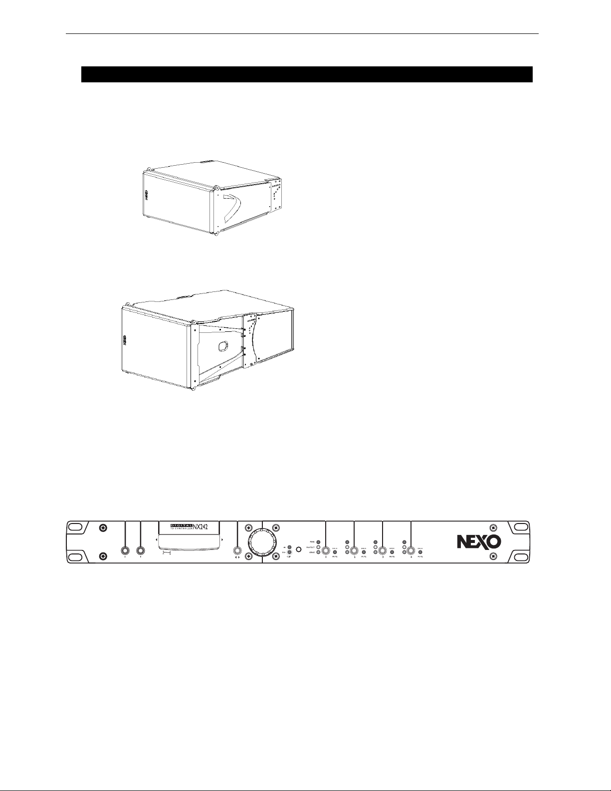
• D10 is a 10° Tangent Array Module. It
comprises 2 x8” (20cm) 8 Ohms LF D rivers
(side firing), 1x12” (30cm) Neodynium 16
ohms LF/MF driver (front) and 1x3” voice
coil, 1.4” Throat 16 Ohm HF Driver loaded
by a 5° Hyperboloid Reflective
Wavesource™.
• Geo Sub is a Cardioid Dipole Sub-bass. It
comprises 1x18” (46cm) Long Excursion
Neodymium 8 Ohm Driver and 2x 12”
(30cm) Neodynium 16 ohms LF drivers,
controlled by DSP advanced proprietary
algorithm, producing a 1 20° x 120° car dioid
pattern. Can be used in conjunction with
GeoD in flown clusters or in ground-stacked
configuration.
• NX242 Digital TDcontroller and NXtension-ES4 provides comprehensive control of GEO D
loudspeakers in multiple configurations. It allows Ethersound
TM
digital audio networking, as well
as remote control for all units in the network.
For a complete description of this unit, please refer to the NX242 User Manual. The NX242 DSP
algorithms and parameters are fixed in software and updated regularly: please consult the NEXO
web site (www.NEXO.fr or w ww.NEXO-sa.com) for the latest software releases.
GeoD Passive mode
Crossover 80Hz
Page 9
INTRODUCTION Page 9/97
• GEO D Array Flying System. A fully integrated and accurate flying system that
provides safe, flexible and simple means of flying GEO D Tangent Arrays. NOTE:
GEO Tangent Arrays control the dispersion of acoustic energy with a high de gree of
precision. Inclinometers and laser aiming tools are essential to ensure proper
audience coverage when installing a GEO Tangent Array.
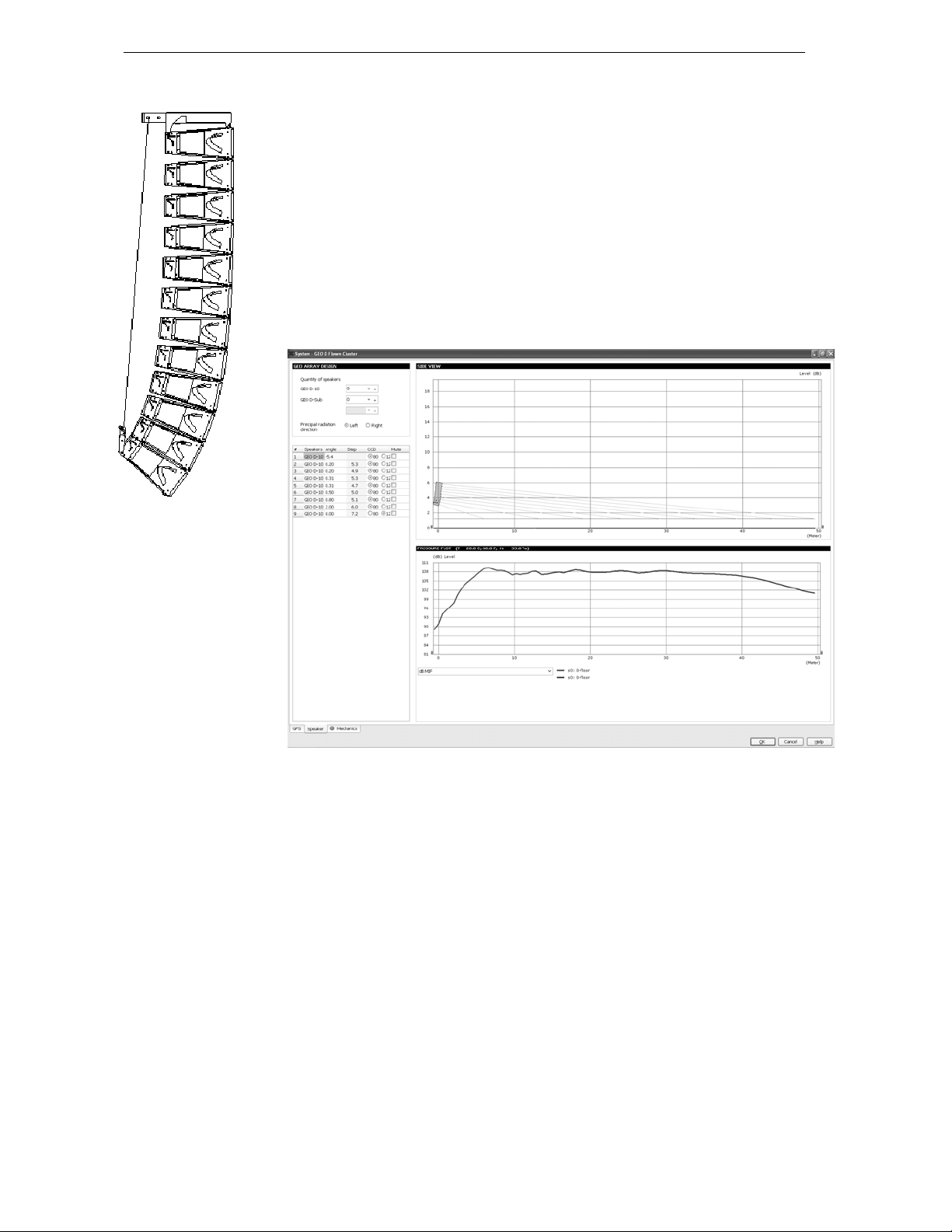
• NS-1 simulation software (previously GEOSoft2) assists in the design and
implementation of vertical tangent GEO arrays. Please consult the NEXO web site
(www.NEXO.fr or www.NEXO-sa.com) for the latest software releases.
Please devote your time and attention to reading this manual. A comprehensive
understanding of GEO theory, tangent arrays, and specific features of GEO D10 and
GEO SUB and will help you to operate your system at its full potential.
Page 10
Page 10/97 GEO D GENERAL SET-UP INSTRUCTIONS
IN
OUT
2 GEO D GENERAL SET-UP INSTRUCTIONS
2.1 Speaker Wiring
2.1.1 GEO D10 connectors
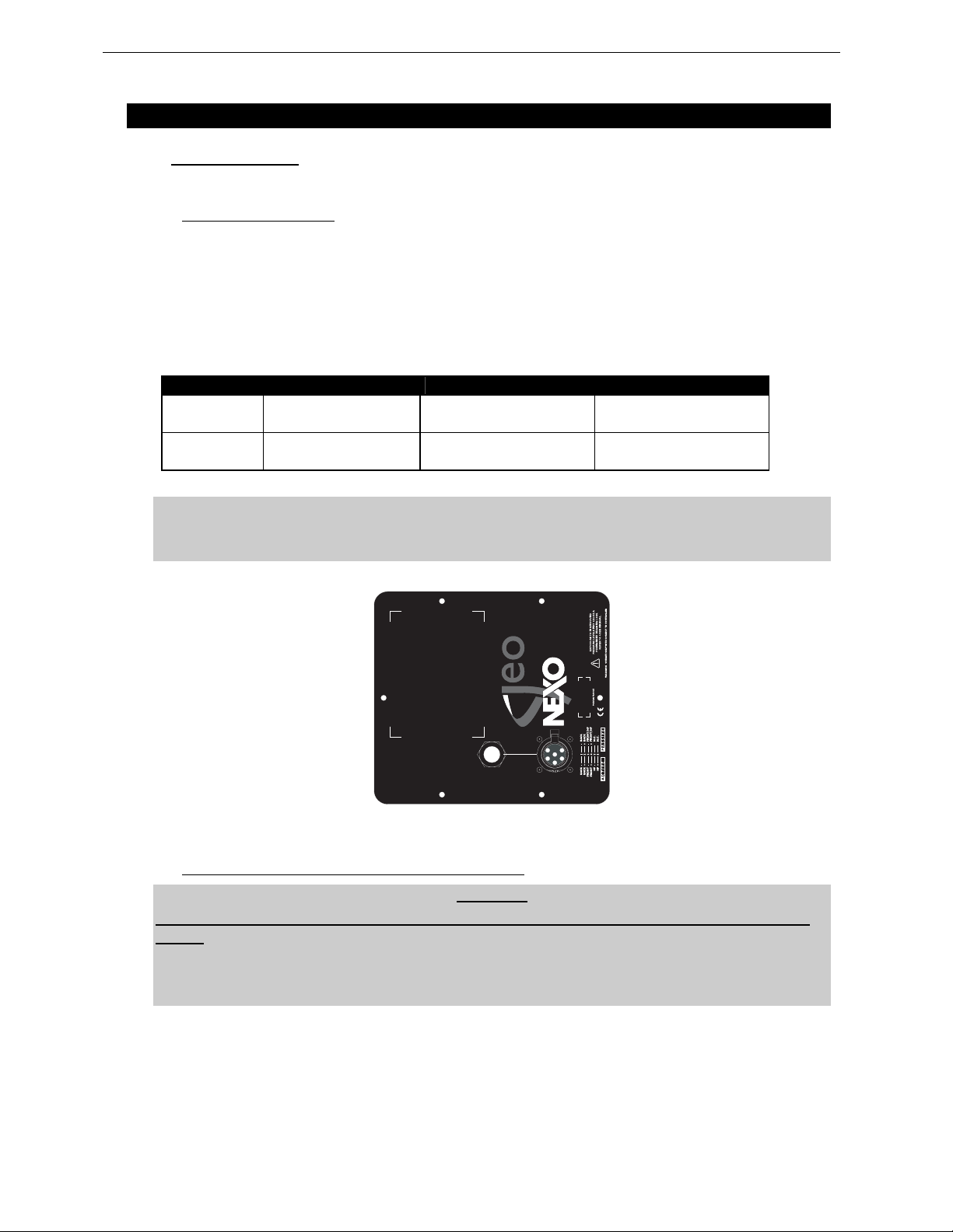
GEO D’s are connected to power amplifiers via one AP6 Male Connector (GEOT-612M) on a link cable
that is stowed in the rear vent port. One EP6 Female Chassis (GEOT-613F) on the back connector
panel is used as output to feed the next GEO D.
A wiring diagram is printed on the connection panel located on the back of each cabinet. The EP6 / AP6
connectors are linked in parallel within the enclosures (see the Connections Diagrams section of this
manual).
EP6/AP6 Pin # 1 / 2 3 / 4 5 / 6-
GEO D10
Passive Mode
GEO D10
Active Mode
High voltages and currents are delivered from the amplifiers to the GEO D system.
Rear 8” LF - 16 Ω
1 Negative – 2 Positive
Rear 8” LF - 16 Ω
1 Negative – 2 Positive
Front 12” LF/MF & 1.4”HF - 16 Ω
3 Negative – 4 Positive
Front 12” LF/MF - 16 Ω
3 Negative – 4 Positive
IMPORTANT
NEVER USE a male AP6 connector to feed the signal:
Not Connecte d
1.4” HF – 16 Ω
5 Negative – 6 Positive
REFER TO USER MANUAL.
EXPOSURE TO HIGH SOUND
PERMANENT HEARING LOSS.
PRESSURE LEVELS MAY CAUSE A
IN
OUT
GEO D10 REAR CONNECTOR PANEL
2.1.2 Configuring GeoD10 for Passive or Active Mode
WARNING
GEO D SERIAL #0100 to #1610 PASSIVE FI LTERS DO NOT OPERATE P ROPERLY IN ACTIVE
MODE:
IF YOUR GEO D’s ARE WITHIN THESE NUMBERS, PLEASE CONTACT NEXO OR YOUR LOCAL
DISTRIBUTOR SO THAT INSTRUCTIONS AND COMPONENTS ARE SENT TO YOU FOR FILTER
MODIFICATION
Page 11
GEO D GENERAL SET-UP INSTRUCTIONS Page 11/97
(
p
GEO D SERIAL #0100 to #1610
Please contact NEXO or your local distributor so that instructions and components are sent to you for
filter modification
GEO D Serial #1611 to above
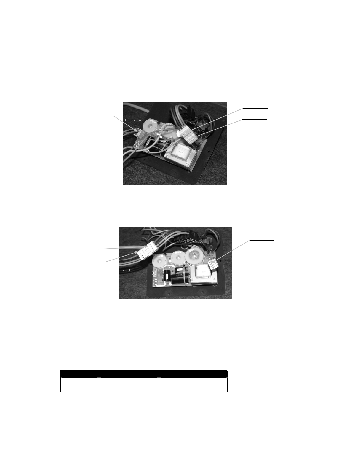
Configuring for Passive Mode (default configuration)
• Connector A & B are link together.
• Speaker Connector is in the CN1 (passive) connector located on the PCB
Speaker Connector
Configuring for Active Mode
• Speaker connector is directly plugged in connector B.
• Connector A is not used, PCB is byp assed.
Connector B
S
eaker Connector
2.1.3 GEO SUB connectors
The GEO SUB’s are connected to power amplifiers via NL4FC SPEAKON connectors (not supplied). A
wiring diagram is printed on the connection panel located on the back of each cabinet. The in/out pins of
the SPEAKON sockets are identified. The sockets are connected in parallel within the enclosures (see
the Connections Diagrams section of this manual).
NL4FC # 1- / 1+- 2- / 2+
GEO SUB
Rear 12”’s VLF - 8 Ω
1(-) Negative – 1(+) Positive
Front 18” VLF-LF - 8 Ω
2(-) Negative – 2(+) Positive
Connector B
Connector A
Connector A
unused)
Page 12
Page 12/97 GEO D GENERAL SET-UP INSTRUCTIONS
2.1.4 Cabling
NEXO recommends the exclusive use of multi-conductor cables to connect the system: the cable kit is
compatible with all the cabinets, and there is no possible confu sion between LF, MF and HF sections.
Cable choice consists mainly of selecting cables of the correct sectional dimension (size) in relation to
the load resistance and the cable length. Too small a cable section will increase both its serial
resistance and its capacitance; this reduces the electrical po wer delivered to the loudspeaker and can
also induce response (damping factor) variations.
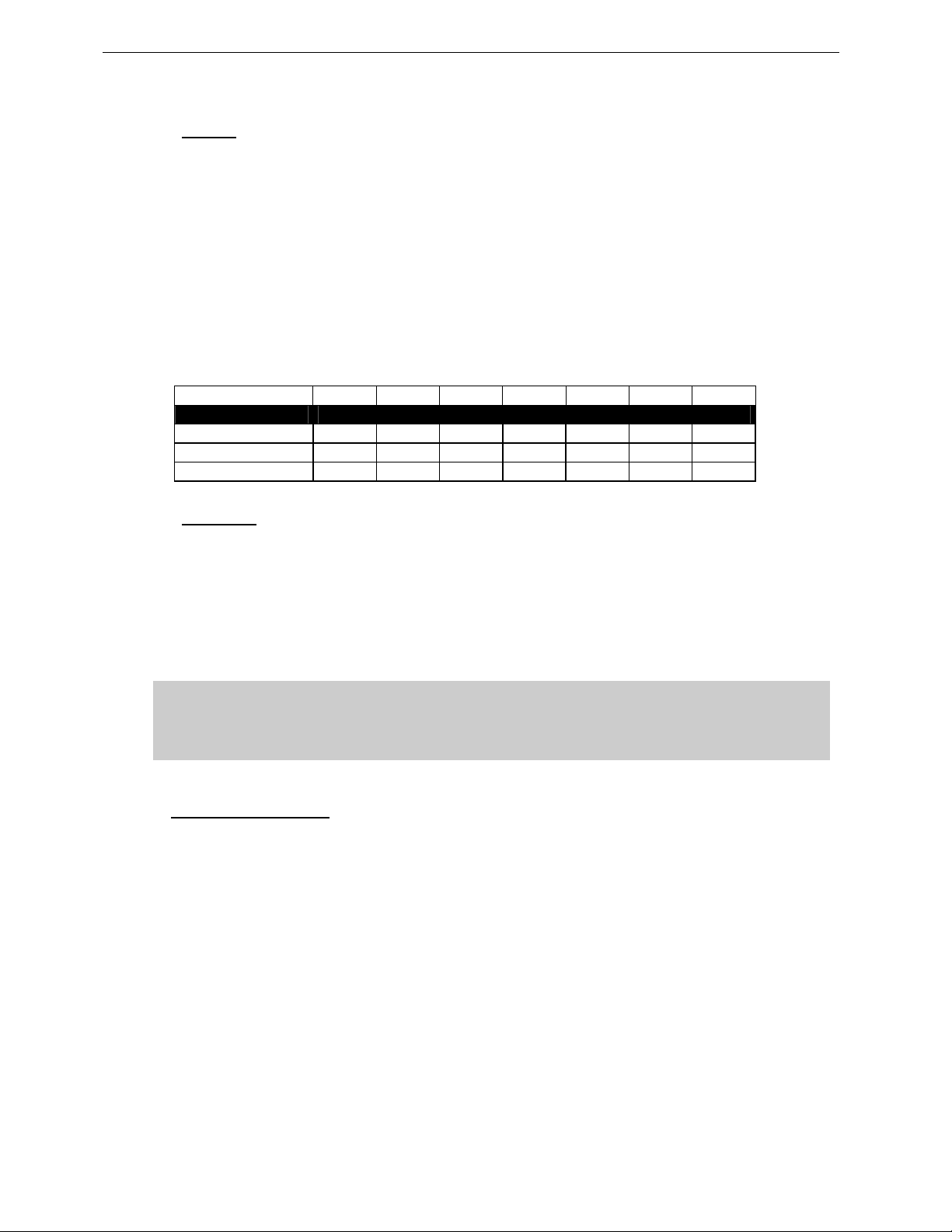
For a serial resistance less or equal to 4% of the load impedance (damping factor = 25), the maximum
cable length is given by:
= Z x S S in mm2, Z in Ohm, L
L
max
The table below indicates these values, for 3 common sizes.
in meters
max
Load Impedance (Ω)
Cable section Maximum Length (meters)
1,5 mm² (AWG #14) 3 4.5 6 9 12 18 24
2,5 mm² (AWG #12) 5 7.5 10 15 20 30 40
4 mm² (AWG #10) 8 12 16 24 32 48 64
2.1.5 Examples:
• The GEO D10 LF section has a 16 Ohms nominal impedance, so 4x GEO D10 LF section wired
in parallel will present a 16/4 = 4 Ohm load impedance. The maximum acceptable 2x2.5 mm
(AWG #12) cable length L
• The GEO SUB subwoofer has a 2 x 8 Ohms nominal impedance, therefore 2 GEO SUB’s wired
in parallel will present a 2 x 4 Ohm load impedance. The maximum acceptable 2x4 mm
#10) cable length L
Long speaker cables induce capacitive effects – up to hundreds of pF depending on the
quality of the cable - with a low-pass effect on high frequencies. If long speaker cables
must be used, ensure that they do not remain coiled while in use.
2.2 Amplifier Selection
NEXO recommends high power amplifiers in all cases. Budget constraints are the only reason to select
lower power amplifiers. A lower power amplifier will not reduce the chances of driver damage due to
over-excursion, and may actually increase the risk of thermal damage due to sustained clipping. If an
incident occurs on an installation without protection, the fact that amplifiers only generating half their
rated output power (-3dB) are used will not change anything in respect of possible damage. This is due
to the fact that the RMS power handling of the weakest component in the sys tem is alwa ys 6 to 10 dB
lower than the amplifier rating.
2 3 4 6 8 12 16
for such a cl us ter is 10 m et er s.
max
is then 16 meters.
max
IMPORTANT
2
(AWG
2
Page 13
GEO D GENERAL SET-UP INSTRUCTIONS Page 13/97
2.2.1 GEO D10 recommended amplification
GEO D10 is rated for very high power handling and has a 16 Ohms nominal impedance per channel
(Passive 2 ways or Active 3 ways).
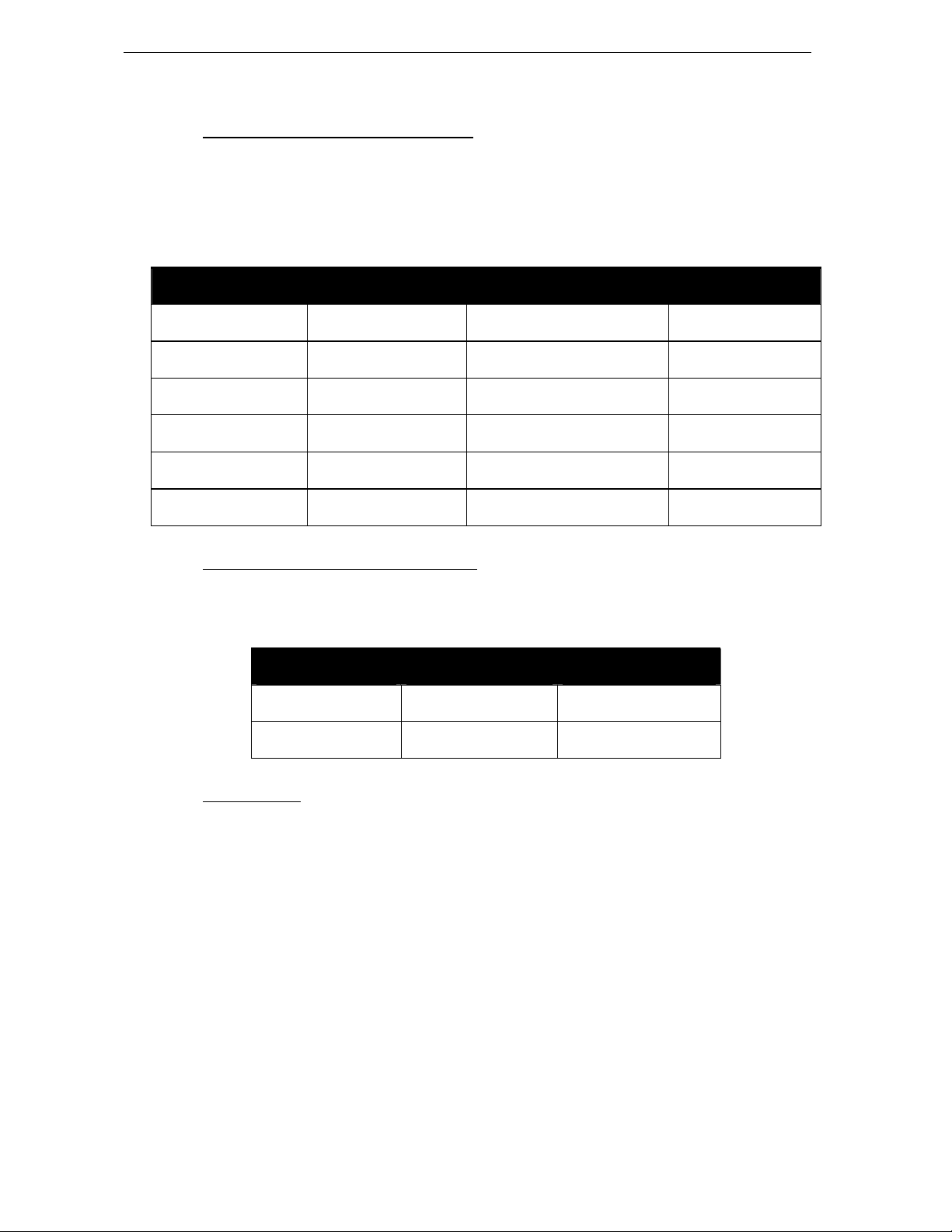
These high impedance values allow connection of 3 to 6 cabinets in parallel for each amplifier channel.
Nexo recommends amplifiers in agreement with table below:
Recommended
Amplifier#
GEO D10 Passive Mode
3 in parallel (5.3 Ohms load)
GEO D10 Active Mode
3 in parallel (5.3 Ohms load)
GEO D10 Passive Mode
4 in parallel (4 Ohms load)
GEO D10 Active Mode
4 in parallel (4 Ohms load)
GEO D10 Passive Mode
6 in parallel (2.7 Ohms load)
GEO D10 Active Mode
6 in parallel (2.7 Ohms load)
Channel 1
LF Rear
1750 to 3100 W / 4 Ohms 1750 to 3100 W / 4 Ohms
1750 to 3100 W / 4 Ohms 1750 to 3100 W / 4 Ohms 875to 1550 W / 4 Ohms
2000 to 3600 W / 4 Ohms 2000 W to 3600 W / 4 Ohms -
2000 to 3600 W / 4 Ohms 2000 to 3600 W / 4 Ohms 1000 to 1800 W / 4 Ohms
3300 to 6000 W / 2 Ohms 3300 to 6000 W / 2 Ohms
3300 to 6000 W / 2 Ohms 3300 to 6000 W / 2 Ohms 1650 to 3000 W / 2 Ohms
LF/MF Front + HF in Passive Mode
Channel 2
Channel 3
HF in Active Mode
2.2.2 GEO SUB recommended amplification
The GEO SUB requires two amplifier channels delivering separately processed signals to produce its
directional pattern.
Recommended
Amplifier#
GEO SUB
Single (8 Ohms load)
GEO SUB
2 in parallel (4 Ohms load)
Channel 1
VLF Rear
1000 to 2000 W / 8 Ohms 1000 to 2000 W / 8 Ohms
2000 to 4000 W / 4 Ohms 2000 to 4000 W / 4 Ohms
Channel 2
VLF-LF Front
2.2.3 Current rating
It is very important that the amplifier behaves correctly under low load conditions. A speaker system is
reactive by nature: on transient signals like music it will require four to ten times more instantaneous
current than its nominal impedance would indicate. Amplifiers are generally specified by continuous
RMS power into resistive loads, however the only useful information about current capacity is the
specification into a 2 Ohm load. It is possible to perform an amplifier listening test by loading the amps
with twice the number of cabinets considered for the application (2 speakers per channel instead of one,
4 instead of 2) and running the amps up to the onset of clipping. If the signal does not noticeably
deteriorate, the amplifier is well adapted (overheating after approximately ten minutes is normal but
thermal pro tection must not operate too quickly after starting this test).
Page 14
Page 14/97 GEO D GENERAL SET-UP INSTRUCTIONS
2.2.4 Amplifier settings
Gain valu e
Gain is the key to correct alignment of the system. It is especially important to know the gain of all
amplifiers use d in you r s et- up. The t ol er ance sh ould be about ±0.5 dB. In practice this can be difficult to
achieve because:
• Some amplifier brands have an identical input sensitivity for models of different power rating (this
infers a different voltage gain for each model). For example, a range of amplifiers with different
power outputs, all having a published input sensitivity of 775mV/0dBm or 1.55V/+6dBm, will have
a wide range of actual gains – the higher the power, the greater the gain.
• Various other brands may offer constant gain but only within a given product range, for example
they may fit fixed input sensitivity only on their semi-professional amps.
• Even if a manufacturer applies the constant gain rule to all models, the value selected will not
necessarily be the same as that chosen by other manufacturers.
• Some products can exhibit manufacturing tolerances for the same model of ±1dB or more. Some
amplifiers may have been modified, possibly without any label indicating the new values. Others
may have gain switches fitted internally where it is impossible for the user to v erify the actual
setting without opening the amplifier casing.
• In cases where you don't know the gain of your amplifier (or want to check it) please follow this
procedure:
1) Unplug any loudspeakers from the amplifier outputs
2) With a signal generator, feed a sine wave at 1000Hz at a known voltage (say 0.5V) to
the input of the amplifier under test
3) Measure the voltage at the output of the amplifier
4) Calculate the gain using the formula Gain = 20 * LOG10(Vout/Vin).
Some examples:
Vin / Gain 20dB 26dB 32dB 37dB (1.4V sensitivity / 1350Wrms)
0.1 V 1 V 2 V 4 V 7.1 V
0.5 V 5 V 10 V 20 V 35.4 V
1 V 10 V 20 V 40 V 70.8 V
Remember that constant sensitivity settings will give a different gain value when the amplifier power is
different.
NEXO recommends low gain amplifiers: +26dB is recommended, as it is at the same time adequately
low and quite common amongst amplifier manufacturers. This gain setting improves signal to noise ratio
and allows al l prec ed ing el ec tron ic eq uip ment , inc lud ing th e NX 24 2 TDc ont rol le r, to ope rat e at opt imu m
level. Remember that using a high gain amplifier will raise the noise floor proportionally.
Operating Mode
Most two channel amplifiers available on the pro-audio market have the following operating modes:
• Stereo:
two fully independent channels deliver identical power into identical loads
NEXO recommends Stereo Mode for all amplifier channels feeding GEO D10’s and GEO SUB’s.
Page 15

GEO D GENERAL SET-UP INSTRUCTIONS Page 15/97
• Bridge-Mono:
reversed phase. The (single) load is connected between the two positive channel outputs using a
suitable connection. While the total output of the amplifier remains the same, the available output
voltage, the minimum impedance that can be connected and the voltage gain are d oubled as
compared with stereo operation. Typically, only channel 1 input is active. Positive and negative
output connections vary depending on amplifier manufacturers.
NEXO does not recommend Bridge Mono Mode unless amplifier power is clearly not sufficient.
the second signal channel processes the same input as the first channel, but with
IMPORTANT
When in Bridge-Mono mode, check your amplifier user manual for proper connection of
outputs 1(+) and (2+) in relation to input phase.
• Parallel-mono: the output terminals of the two channels are configured in parallel using an
internal relay. The (single) load is connected either to the output of channel 1 or to that of channel
2 (as if in stereo). While the total output of the amplifier remains the same the output voltage level
is also the same as in stereo mode. The minimum impedance that can be connected is reduced
by half due to the fact that current capability is doubled. T ypically, only channel 1 input is active.
NEXO does not recommend Parallel-Mono Mode for any GEO D10 or GEO SUB amplification.
Warning on amplifiers signal processing features
Some high-end amplifiers may include signal processing funct ions similar to those found in the NX242
TDcontroller ("loudspeaker offset integration", "limiter", "compressor," etc.). Moreover, when this
processing is digital, computation latency time can introduce a few milliseconds delay from input to
output. These functions are not adapted to specific system requirements and may interfere with the
complex protection algorithms used in the NX242.
NEXO do not advise using other protection systems in conjunct ion with the NX242 and they should be
disabled.
IMPORTANT
For proper system protection, no latency time or non-linear devices should be
introduced between the output of the NX242 TDcontroller and the input of loudspeakers
through use of DSP modules such as internal amplifier signal processing.
2.2.5 Example
For a 6 GEO D10 and 2 GEO SUB cluster, and considering an amplifier model which is capable of
delivering 2 x 3300W into 2 Ohms or 2 x 2300W into 4 Ohms, NEXO recommends the following
quantities and settings:
• GeoD Passive Mode:
2 amplifiers, 3 x GEO D10 per amplifier (1 channel LF rear, 1 channel LF/MF/HF Front), mode
switch in Stereo position, Gain switch in 26 dB gain position, all dynamic or filter processing
switches off.
• GEO SUB :
1 amplifier, 2 x GEO SUB per amplifier (1 channel VLF rear, 1 channel VLF/LF Front), mode
switch in Stereo position, Gain switch in 26 dB gain position, all dynamic or filter processing
switches off.
Which gives a total of 3 identical amplifiers for such a cluster.
Page 16
Page 16/97 NS-1 SIMULATION SOFTWARE
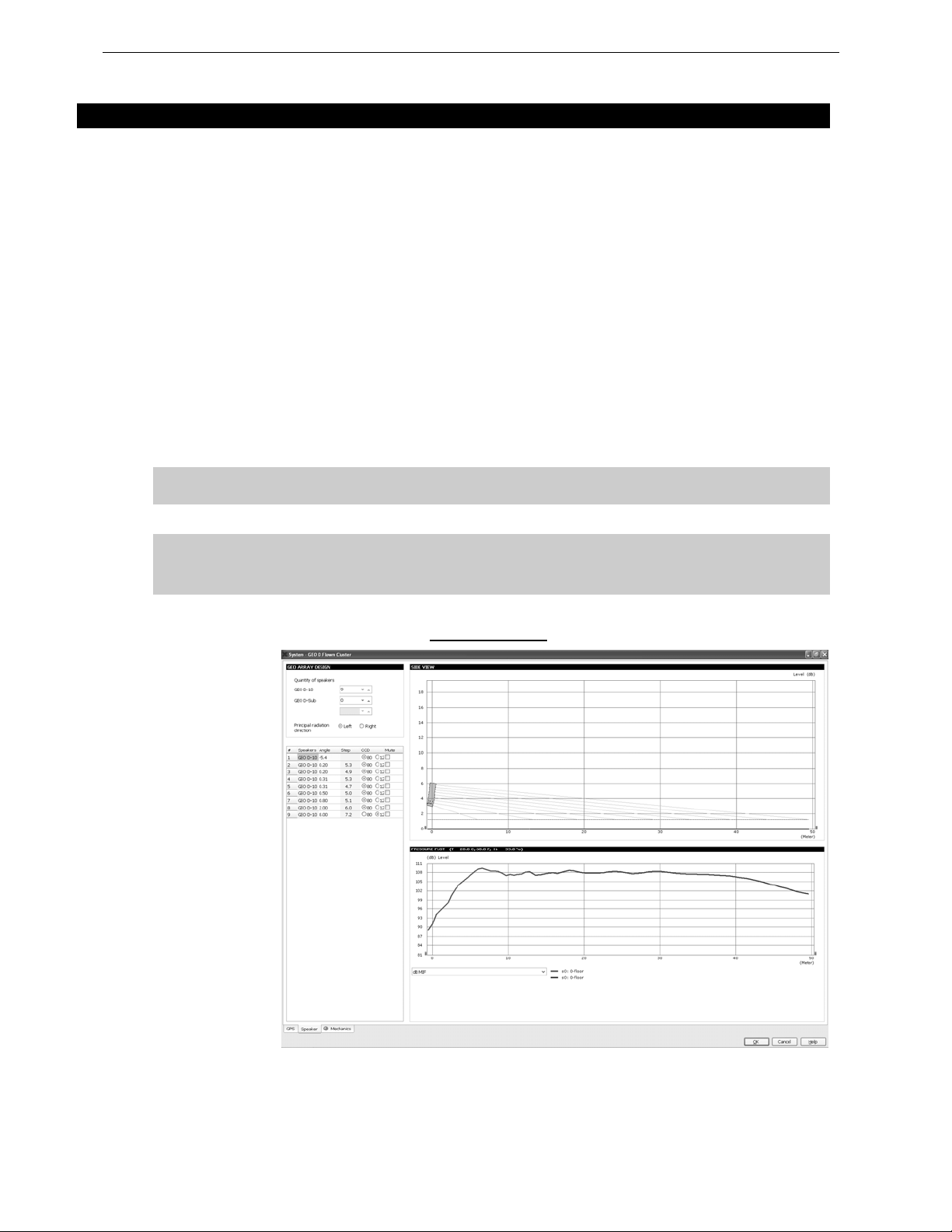
3 NS-1 SIMULATION SOFTWARE
NS-1 software is a R&D simulation tool derived application. It processes measured speaker data with
complex mathem atical algorit hms to ass ist the us er in optimizing system design. Due to the complexity
of the interaction of multiple cabinets, it is simply not possible to reliably design curved vertical arrays
without using the processing power of a computer to predict the optimum array structure for a given
audience geometry. The design logic is far more complex than looking at a section drawing of the
venue, measuring the overall angle needed to cover the audience from the cluster location, and dividin g
by 10 degrees to determine the require d amount number of GEO D10 & GEO SUB cabinet s.
NS-1 is an easy to use tool that allows to shape the energy leaving the cluster to fit the audience. It
predicts pressure levels radiated from the system to ensure enough cabinets are provided for the
application, as well as mechanical constraints for safe flown systems.
In addition, it provides mechanical information for all clusters in agreement with Structural Analysis
Reports (available in the Help section): dimensions, weight, gravity center position, forces, moments,
working load and safety factor.
Geo D10 and GEO SUB Structural Analysis Reports have been validated by German Certification
Organization RWTUV systems GmbH.
NS-1 installation package includes all NEXO User Manuals, Structural Analysis Reports and Certificates
PDF files (which can be found in the last section of User Manuals).
NS-1 is a freeware available for all Nexo users. Please contact your local distributor for
licensing procedure.
IMPORTANT
Never install a GEO D / GEO SUB cluster without checking its acoustical performances
and mechanical safety in NS-1 prior to installation.
Any question or bug report please contact [email protected]
NS-1 GEO S12 ACOUSTIC PAGE
Page 17
CONFIGURABLE DIRECTIVITY DEVICE Page 17/97
4 CONFIGURABLE DIRECTIVITY DEVICE
The GEO Wavesource controls dispersion of acoustic energy using an hyperboloid acoustical reflector
in the “coupling plane” (the vertical plane of a curved vertical tangent array) and a dif fraction slot in the
“non-coupling plane” (the horizontal plane of a curved vertical tangent array). The patented
Configurable Directivity Device consists of bolt-on flanges that alter the diffraction slot’s exit flare rate.
4.1 Installing & removing GEO’s Configurable Directivity flanges
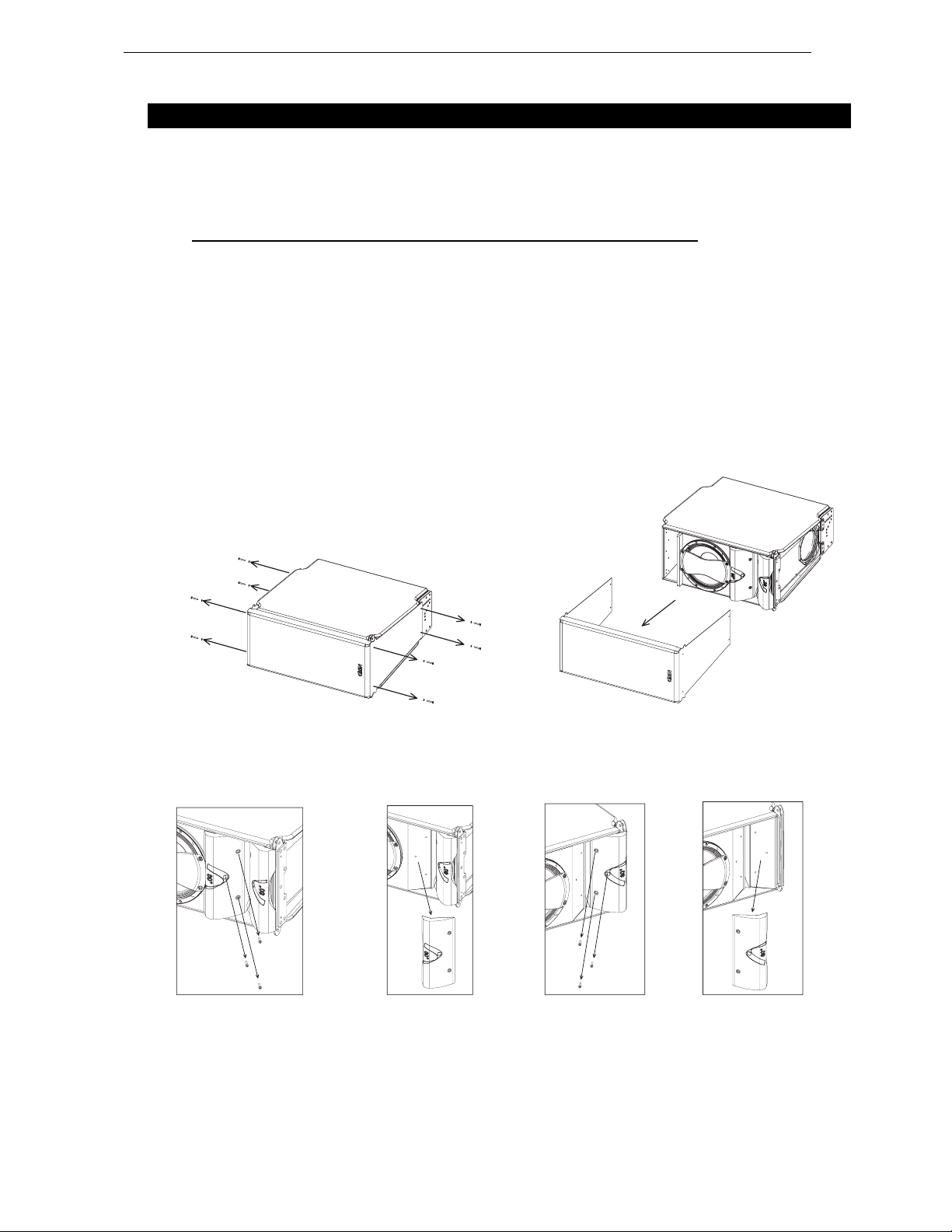
GEO D10 are shipped in the 80° dispersion configuration, with the 120° flanges in a separate bag.
To change dispersion in the non-coupling plane to 120°:
• remove the front grill (drawings below);
• remove the three TORX (head 25) screws per flange on each side of the GEO Waveguide
(drawings below) ;
• install the 120° flanges with the six TORX screws
• re-install the grid, being carefull that the NEXO logo must be on the GEO Waveguide side.
REMOVING THE GRILL
REMOVING THE FLANGES
Page 18
Page 18/97 CONFIGURABLE DIRECTIVITY DEVICE
4.2 When & where to use Configurable Directivity flanges
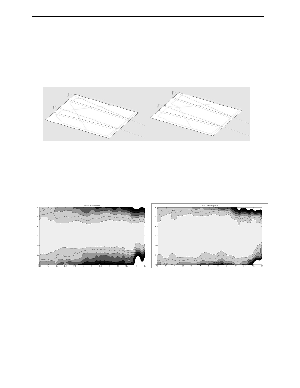
The diagrams show audience area coverage for a stereo system. While the GEO cluster will deliver
even SPL from the front to the rear of this audience area, there are “holes” near the front in the centre
and at the outside edges. We cannot fill the outside coverage gaps without enlarging the centre gap,
and vice versa (left figur e below).
If 120° Configurable Directivity Devices are installed at the bottom cabinet of the clusters, coverage will
look more like the pattern in right figure below.
-6dB coverage, all GEO D10’s in 80° configuration -6dB coverage, bottom GEO D10’s in 120° configuration
In curved vertical arrays, the 120° Configurable Directivity Device can be used:
• On the bottom row of curved vertical arrays, to fill in coverage gaps in the front rows.
• On all rows of curved vertical arrays, in cases where 120° of horizontal coverage is
preferred to 80°.
Figure below shows isocontour coverage for 80° and 120° configurations.
FIGURE 3: 80° AND 120° CONFIGURATIONS ISOCONTOUR COVERAGE
Page 19

GEO D RIGGING PROCEDURE Page 19/97
5 GEO D RIGGING PROCEDURE
Before proceeding with assembly of GEO D arrays, please ensure that the components are present and
undamaged. A component list is appended to this manual. In the event of any shortage, please contact
your supplier.
For maximum efficiency the GEO D rigging system requires three experienced persons for set-up:
typically one motor hoist operator, and one GEO D operator per side of the array. Good synchronisation
and crosscheck between the operators are key elements for a reliable and safe set-up.
5.1 SAFETY FIRST
GEO D / GEO SUB Rigging System structural computations and related documents are available in
Geosoft2 or at Nexo ([email protected]
We include this section to remind you of safe practice when flying the GEO D / GEO SUB system.
Please read it carefully. However, user must always apply his or her knowledge, experience and
common sense. If in any doubt, seek advice from your supplier or NEXO agent.
This manual offers guidance only for GEO D / GEO SUB loudspeaker systems. References in this
manual to other rigging equipment such as motor hoists, steels, shackles etc. are made to clarify the
description of GEO D / GEO SUB procedures. The user must ensure that operators are properly trained
by other agencies in the use of these items.
The GEO D / GEO SUB Rigging System has been optimised for the deployment of curved vertical
tangent arrays of GEO D / GEO SUB loudspeakers. Vertical angle adjustment between cabinets has
been limited to specific settings to ensure correct acoustic coupling.
The GEO D / GEO SUB Rigging System is a professional precision tool set, and should be handled with
extreme care. Only persons who are fully conversant with the operation of the GEO D / GEO SUB
Rigging System and provided with suitable safety equipment should deploy GEO Arrays. Misuse of the
GEO D / GEO SUB Rigging System could lead to dangerous consequences.
Used and maintained correctly, the GEO D / GEO SUB Rigging System will give many years of reliable
service in portable systems. Please take the time to read and understand this manual. Always use
GEOSoft2 to determine the optimum angle settings for a particular venue, hang point and curved
vertical GEO D / GEO SUB. Applied forces and moments are strongly cabinet quantity and angle
configuration dependent. Cluster configuration must be implemented and validated in Geosoft2 prior to
installation.
) upon request.
5.1.1 Flown Systems Safety
• Always inspect all the rigging components and cabinets for damage before assembly. Pay
special attention to the lifting points, and safety clips. If you suspect that any of the components
are damaged or defective, DO NOT USE THE AFFECTED PARTS. Contact your supplier for
replacements.
• Read this manual carefully. Also be familiar with the manuals and safe working procedures for
any ancillary equipment that will be used with the GEO D / GEO SUB Rigging System.
• Appli ed forces and moments are strongly cabinet quantity and angle configuration dependent.
Cluster configuration must be implemented and validated in Geosoft2 prior to installation.
• Ensure that all local and National regulations regarding the safety and operation of flying
equipment are understood and adhered to. Information on these regulations can usually be
obtained from Local Government Offices.
• When deploying a GEO D / GEO S UB system always wear protective headwear, footwear and
eye protection.
• Do not allow inexperienced persons to handle a GEO D / GEO SUB system. Installation
personnel should be trained in loudspeaker flying techniques and should be fully conversant with
this manual.
Page 20

Page 20/97 GEO D RIGGING PROCEDURE
• E nsure that motor hoists, hoist control systems and ancillary rigging components are currently
certified as safe and that they pass a visual inspection prior to use.
• Ensure that public and personnel are not allowed to pass beneath the system during the
installation process. The work area should be isolated from public access.
• Never leave the system unattended during the installation process.
• Do not place any object, no matter how small or light, on top of the system during the installation
procedure. The object may fall when the system is flown and is likely to cause injury.
• Secondary safety steels must be installed once the system has been flown to the operating
height. Secondary steels must be fitted irrespect ive of requirements of the local s afet y standards
applicable to the territory.
• Ensure that the system is secure and prevented from pivoting around the motor hoist.
• Avoid any form of excessive dynamic loading to the assembly (structural computations on GEO
D / GEO SUB Rigging System are based on a 1/1.2 factor for hoist or motor acceleration).
• NEVER attach any item to the GEO D / GEO SUB system ot her than the GEO D / GEO SUB
accessories.
• When flying outdoor systems ensure that the system is not exposed to excess ive wind or snow
loads and is protected from rainfall.
• T he GEO D / GEO SUB Rigging System requires regular i nspect ion and testing by a competent
test centre. NEXO recommend that the system is load tested and certified annually or more
frequently if local regulations require.
• When de-rigging the system ensure that the same duty of care is given to the proced ure as for
the installation. Pack GEO D / GEO SUB components carefully to prevent damage in transit.
5.1.2 Ground Stacking Safety
Statistically, many more injuries occur due to unstable ground stacked PA systems than those
associated with flown systems. There are several reasons for this fact, however the message is clear:
• Always survey t he supporting structure upon which a ground stack is to be built. Always look
beneath PA wings to inspect the deck support and if necessary ask for the stage scrims and
dressings be removed to allo w access.
• If the stage surface slopes, as it does in some theatres, ensure that the system is prevented from
sliding forwards due to vibration. This may require the fitting of timber battens to the stage floor.
• For outdoor systems ensure that that the system is protected from wind forces which might
cause the ground stack to become unstable. Wind forces can be huge, especially upon l arge
systems, and should never be underestimated. Observe meteorological forec asts, calculate the
“worst case” effect upon the system prior to erection and ensure that the system is secured
appropriately.
• Take care when stacking cabinets. Always employ safe lifting procedures and never attempt to
build stacks without sufficient personnel and equipment.
• Never allow anyone, whether operators, artists or members of the public to climb onto a grou nd
stacked PA system. Anyone who needs to climb over 2m (6 ft) high should be fitted with suitable
safely equipment including a clip-on harness. Please refer to local Health and Safety legislation in
your territory. Your dealer can help with advice on access to this information.
• Apply the same attention to all safety matters when de-stacking systems.
• B e aware that safet y procedures a re as important in the truc k and in the ware house as t hey are
at the venue.
Page 21

GEO D RIGGING PROCEDURE Page 21/97
5.1.3 Contacts
Correct training is fundamental to safe practise when working with loudspeakers flying systems. NEXO
recommend that users contact local industry associations for information on specialist course.
Information for International training agencies can be obtained by contacting either:
The Production Services Association
(PSA),
School Passage,
Kingston-upon-Thames,
KT1 SDU Surrey,
ENGLAND
Telephone: +44 (0) 181 392 0180
ESTA
Rigstar Training and Testing Center
82 Industrial Dr. Unit 4
Northampton, Massachusetts 01060 U.S.A.
Phone: 413-585-9869 -- Fax: 413-585-9872
[email protected]
Entertainment Services & Technology Association
875 Sixth Avenue, Suite 1005
NEW YORK, NY 10001 USA
Phone: 212-244-1505 – Fax: 212-244-1502
[email protected]
- www.esta.org
Page 22
Page 22/97 GEO D RIGGING PROCEDURE
5.2 General Description
5.2.1 GEO D10 and GEO SUB
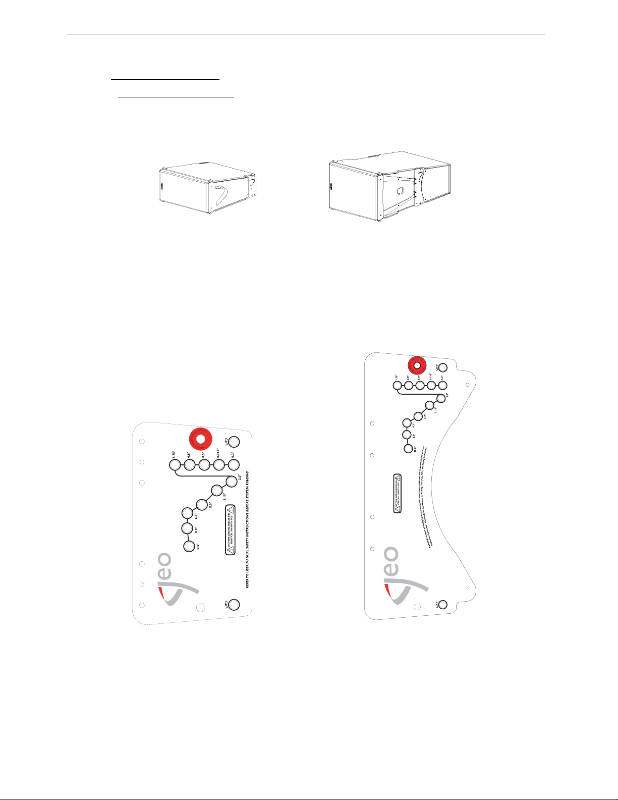
Each GEO D and GEO SUB Array Module includes an individual rigging system, which is mounted at
the NEXO factory.
GEOD10 ARRAY MODULE GEO S SUB ARRAY MODULE
GEO D10 and GEO SUB angle sequences are identical and follow logarithmic scales. Angle setting
values are:
• Bumper to first cabinet (GEO D10 or GEO SUB): 0°
• Cabinet t o cabinet (GE OD10 or GEO SUB): 0.20° - 0.315° - 0.50° - 0.80° - 1.25° - 2.0° - 3.15° -
5.0° - 6.3° - 8.0° - 10°
GEO D10 RIGGING PLATE GEO SUB RIGGING PLATE
Page 23
GEO D RIGGING PROCEDURE Page 23/97
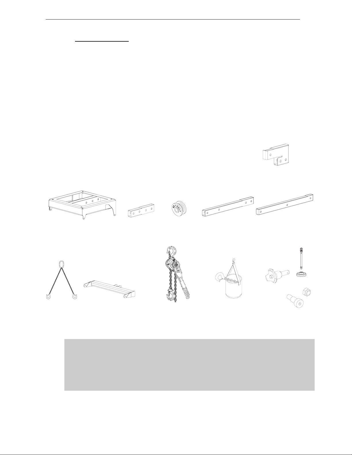
5.2.2 Rigging Accessories
Rigging Ac cessories are:
• Bumper (GEOD-BUMPER)
• Short Extension Bar (GEOD-EXBAR1)
• Compression Wheel for Short Extension Bar EXBAR1 (GEOD-ORP)
• Two legs Bridle (GEO-BRIDLE)
• Long Extension Bar (GEOD-EXBAR2)
• Bottom Extension Bar (GEOD-EXBAR3)
• Front Extension Bar (GEOD-EXBAR4)
• Bottom Bumper (GEOD-BTBUMPER)
• Chain Lever Hoists (LEVA0750 or LEVA1500)
• Chain Bag (CHBAG)
• Push-Pins (BLGEOD)
• Shoulder Bolts an d N ut s (G EOD -BNF IX)
• Bumper Stands stacking kit (GEOD-BUDP)
GEOD-EXBAR4
GEOD-BUMPER GEOD-EXBAR1 GEOD-ORP GEOD-EXBAR2 GEOD-EXBAR3
6 x
GEO BRIDLE GEOD-BTUMPER GEOD-LEVA750 & LEVA150 CHBAG BLGEOD -GEOD-BNFIX
GEOD-BUDP
IMPORTANT
All GEOD / GEO SUB Rigging Components are specifically rated in agreement with
structural co m putations.
Never use other accessories – including push-pins - when assembling GEO D / GEO SUB
clusters than the ones provided by NEXO: NEXO will decline responsability over the
entire GEOD / GEO SUB rigging system if any component is purchased from different
supplier.
x 4
Page 24
Page 24/97 GEO D RIGGING PROCEDURE
5.2.3 Configurations and operating mode
General Pr inciple
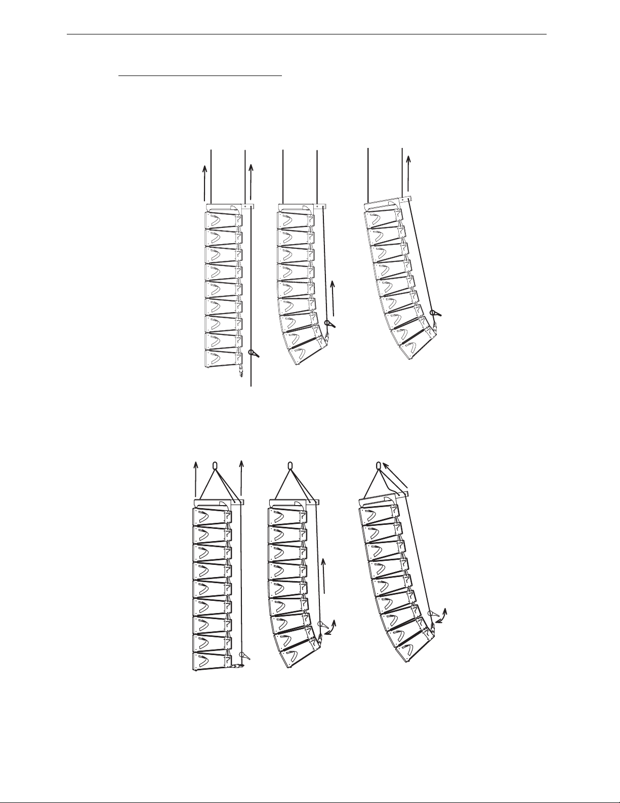
GEO D10 / GEO SUB rigging system operates in compression mode: pull-back force applied between
the extreme bottom cabinet and the top bumper set angles between cabinets. When the array is lifted
into position all cabinets are at 0° (1) and it is only when the pull-up force is applie d that the correct
angles are obtained (2). Bumper angle is then set by adjusting front and rear motors (3).
(1) LIFTING CLUSTER VERTICALLY (2) APPL YING COMPRESSION (3) ADJUSTING BUMPER ANGLE
In case GeoD10 cluster is flown from one rigging point (8 GEO D maximum, no GEO SUB allowed),
array is lifted with all cabinets at 0°. Pull-back force and bumper angle are then set with the Chain Lever
Hoist LEVA750. Please refer to sections below for detailed desc ription.
(1) LIFTING CLUSTER VERTICALLY (2) APPL YING COMPRESSION (3) ADJUSTING BUMPER ANGLE
Page 25
GEO D RIGGING PROCEDURE Page 25/97
ER
ER
gging
ER
GEOD-BUPDP
Described Cases
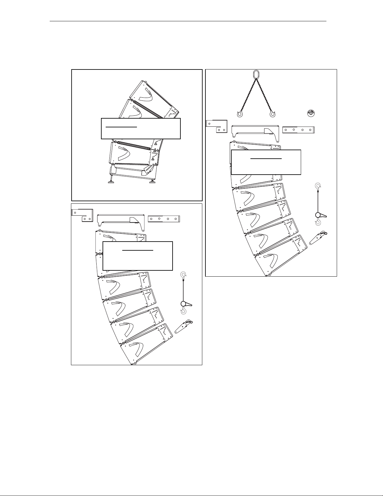
Sections below describe GEO D10 and GEO SUB clusters rigging procedures for the following cases:
GEOD-EXBAR4
Section 5.3
GEOD Ground Stacked
GEOD-BUMP
GEOD-BUMPER
GEOD-EXBAR1
Section 5.5
GEO D Cluster
Two Rigging Points
GEOD-EXBAR4
GEOD-BUMPER
GEO D Cluster
One Ri
LEVA750
GEOD-BTBUMP
GEO-BRIDLE
GEOD-ORP
GEOD-EXBAR1
Section 5.4
Point
LEVA750
GEOD-BTBUMP
Page 26
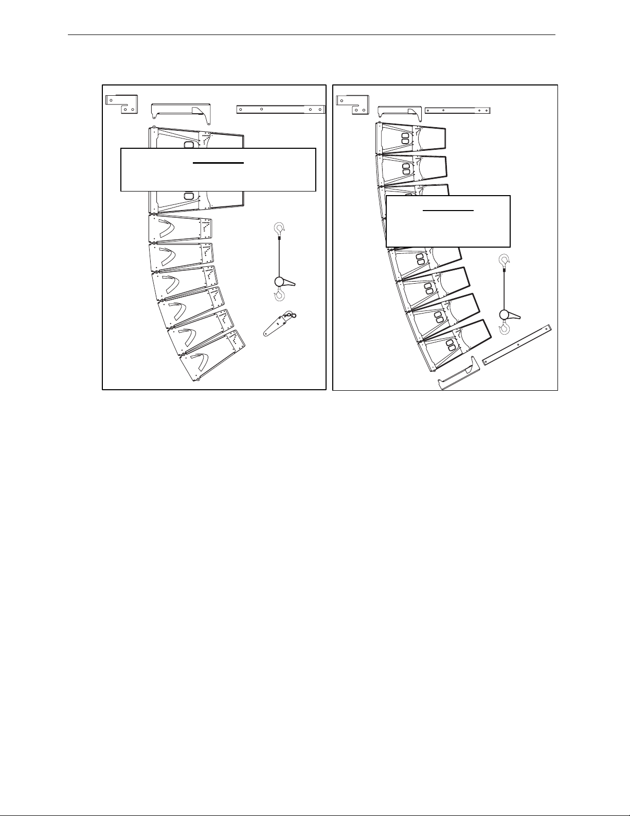
R3
GEOD-EXBAR4
GEOD-EXBAR4
Page 26/97 GEO D RIGGING PROCEDURE
GEOD-BUMPER
GEOD-EXBAR2
GEOD-BUMPER
GEOD-EXBAR2
Combined GEO D – GEO SUB Cluster
Section 5.6
Two Rigging Points
Section 5.7
GEO SUB Cluster
Two Rigging Points
LEVA750
LEVA1500
GEOD-BTBUMPER
GEOD-EXBA
GEOD-BUMPER
Page 27
GEO D RIGGING PROCEDURE Page 27/97
5.3 GEO D – GEO SUB Ground Stacked
Stacking a GEO D10 cluster requires the following accessories:
• 1 x GEO D Main Bumpe r (G EOD- BU MPER )
• 1 x GEO D Bumper Stands kit (GEOD-BUDP)
• 6 x GEOD push-pins per stacked GEO D10 or GEO SUB (BLGEOD )
• or 1 x GEOD shoulder bolts and nuts kit for fixed installations per stacked GEO D (GEOD-
BNFIX)
IMPORTANT
Ensure platform (ground, riser…) is solid enough to support stacked cluster weight
(distributed on four points), and perfectly horizontal.
5.3.1 Allowed stacked configurations
IMPORTANT
Allowed Stacked Configurations are:
- 4 GEO D maximum
- or 1 GEO SUB max (bottom) + 3 GEOD max (top)
- or 2 GEO SUB
Bumper angle must never exceed +/- 6.5°
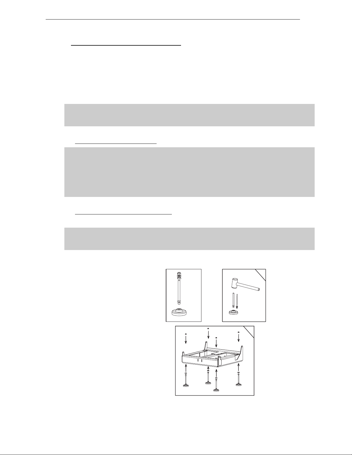
5.3.2 Installing Bumper Stands on Bumper
• Install bumper stands and nuts according to drawing below.
IMPORTANT
Make sure nuts are properly positioned on both sides of the bumper. These are
mandatory for system safety
• Adjust length of each stand so that desired bumper angle is achieved (bumper side edge angle in
relation to horizontal); ensure that bumper front edge is perfectly horizontal;
• Secure nuts.
INSTALLING BUMPER STANDS
x 4
1
2
Page 28
Page 28/97 GEO D RIGGING PROCEDURE
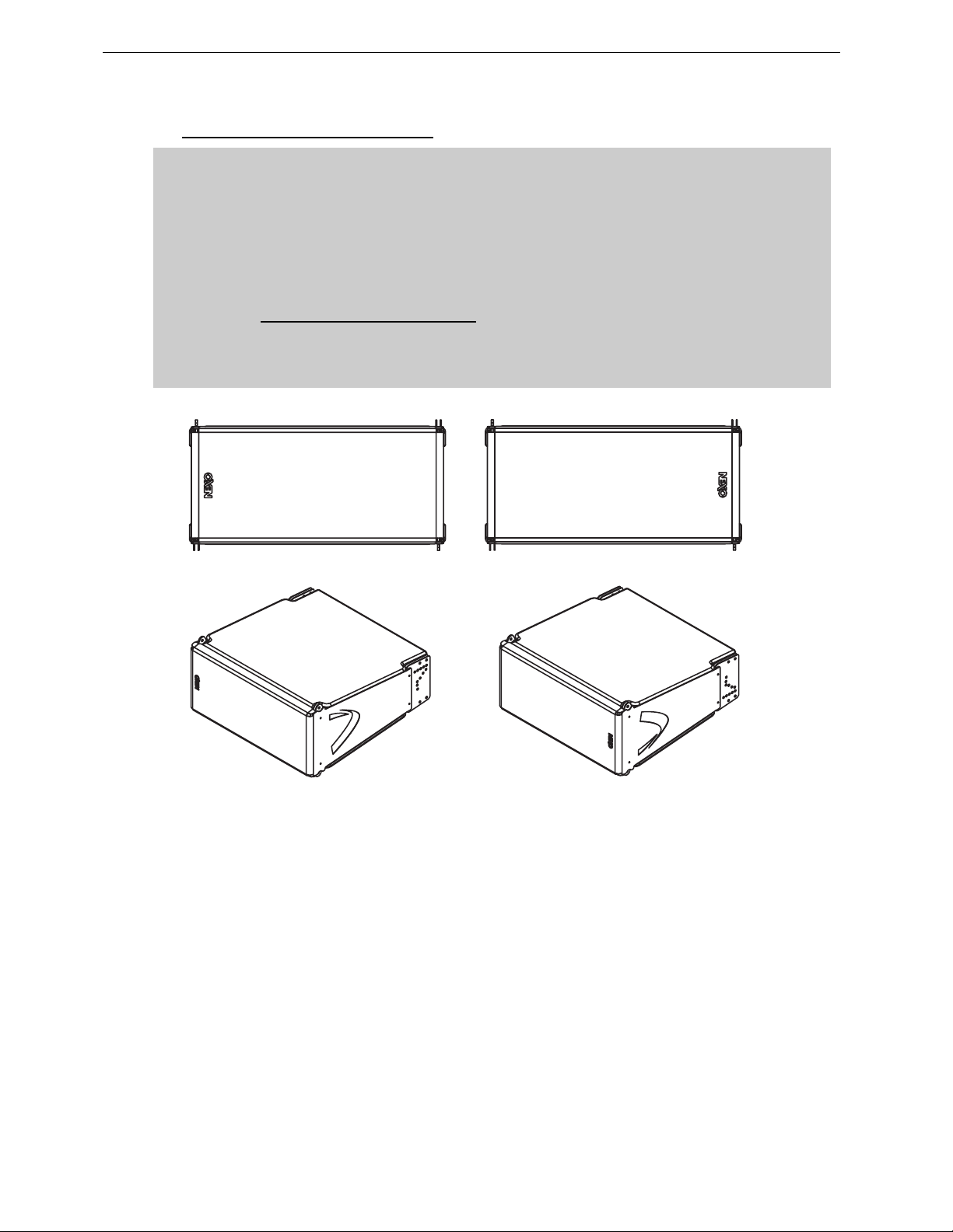
5.3.3 Bumper to first GEO D10 assembly
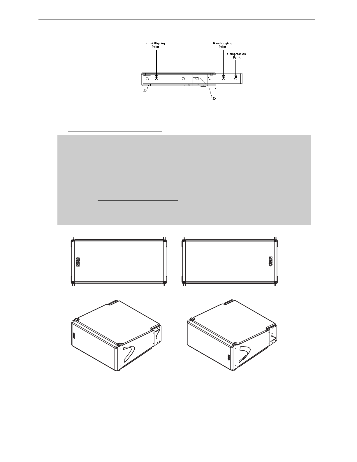
IMPORTANT
GEO D10 can be stacked “Left” or “Right” :
- “Left” means Nexo logo on front grid is left as seen from front;
- “Right” means Nexo logo on front grid is right as seen from front.
GEO D10 can be connected to bumper “Left” or “Right” by simply flippin g the cabinets
upside down: do not reverse rigging plates
Whenever possible, NEXO recommends symmetrical designs (preferably NEXO logo
inwards in stereo configurations)
‘’LEFT’’ CONFIGURATION ’’RIGHT’’ CONFIGURATION
4 push-pins (BLGEOD, 10mm diameter x 20 mm length) connect the bottom GEO D10 to the bumper.
• Position the first GEO D10 on bumper;
• Link the GEO D10 to the bumper assembly using the four 10mm x 20mm push-pins; front
bumper connects at GEO D10 front articulation point, rear bumper connects at “LIFT” GEO D10
rigging plates holes;
• Check that all push-pins are in their locked position.
Page 29
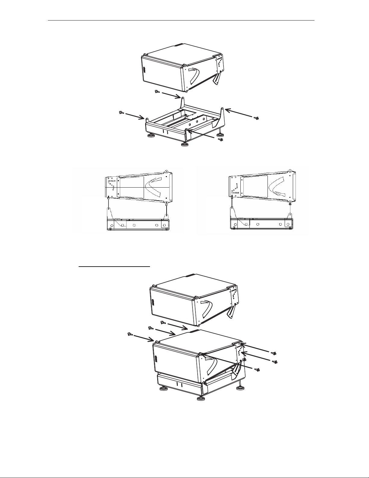
GEO D RIGGING PROCEDURE Page 29/97
BUMPER TO FIRST GEOD ASSEMBLY
‘’LEFT’’ CONFIGURATION ’’RIGHT’’ CONFIGURATION
5.3.4 First to second GEO D 10
FIRST TO SECOND GEO D10
Page 30
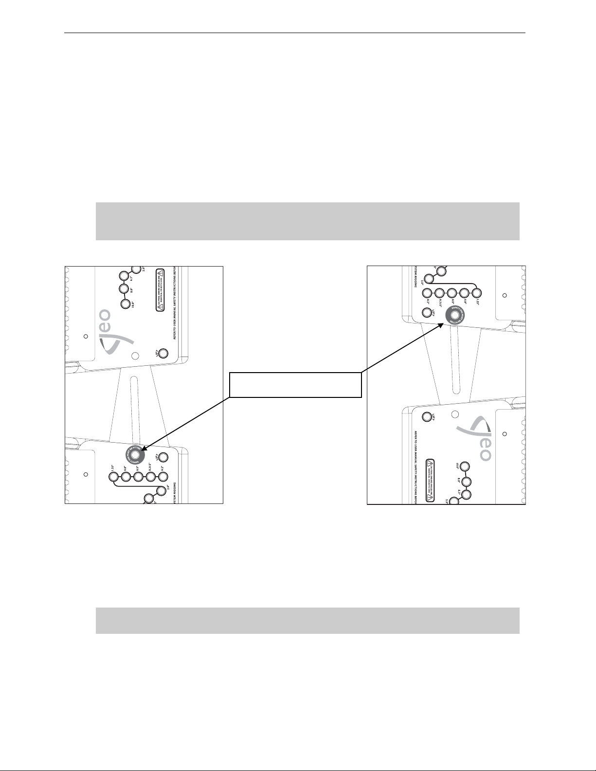
Page 30/97 GEO D RIGGING PROCEDURE
4 push-pins (BLGEOD, 10mm diameter x 20 mm length) connect first to second GEO D10, 2 additional
push pins-are required for angle adjustment.
• Lift and position the next GEO D10 above the assembly, with NEXO logo on the same side than
the lower cabinet.
• Lower top GEO D10 carefully until the first and second GEO D10 si de rigging plate s loc ate. Use
front grid, rear vent ports or handle to guide the assembly. The rigging plates have been
designed to locate against each other and so align the holes correctly.
• Connect the upper GEO D link bar to the lower GEO D rigging plate (or lower link b ar to upper
rigging plate for “Right” configuration) by inserting one 10mm x 20 mm push-pin in the “SAFE TY
PIN MUST BE FITTED” hole on each side (see figure below).
IMPORTANT
The push-pins for “SA FETY PIN MUS T BE FITT ED” holes must always be inserte d first and
stay in position permanently. NEVER REMOVE THEM ONCE CABINETS ARE STACKED.
« SAFETY PIN MUST BE FITTED »
HOLE
• Insert two additional 10mm x 20mm push-pins in the front holes (see figure above).
• Lift Cabinet to release weight from linking bars and insert 1 additional push-pin per side to the
required angle;
• Check that all 6 push-pins are locked.
IMPORTANT
Ensure angle settings are identical on both sides of the cabinet.
Page 31
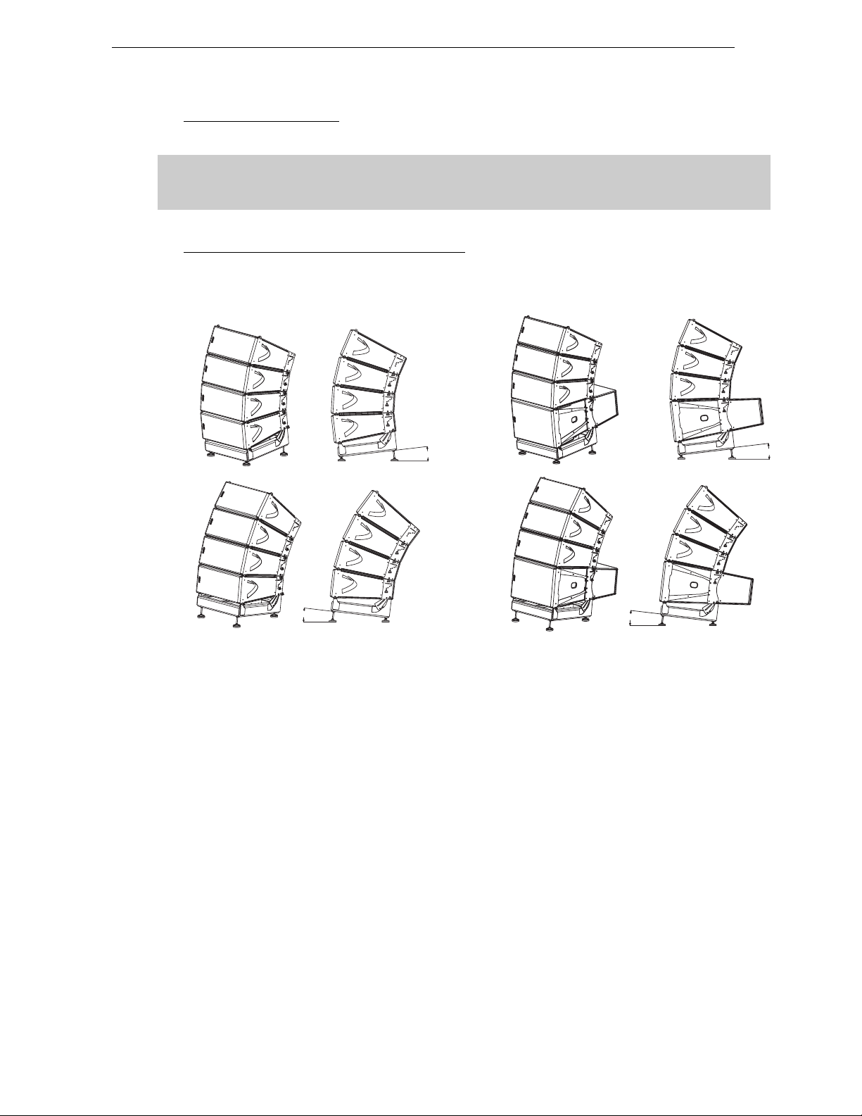
GEO D RIGGING PROCEDURE Page 31/97
5˚
6.5˚
6.5˚
5.3.5 Subsequent GEO D10’s
• Repeat the above section steps, until all GEO D10’s are in place.
IMPORTANT
DO NOT attempt to make any changes to the angle adjustments without releasing weight
on the linking bars.
5.3.6 Ground Stacking GEO SUB with Geo D10’s
Proceed exactly as above, bottom cabinet must always be a GEO SUB.
6.5˚
GEO D10 GEO SUB GEO D10
MAXIMUM ALLOWED STACKED CONFIGURATION
6.
Page 32
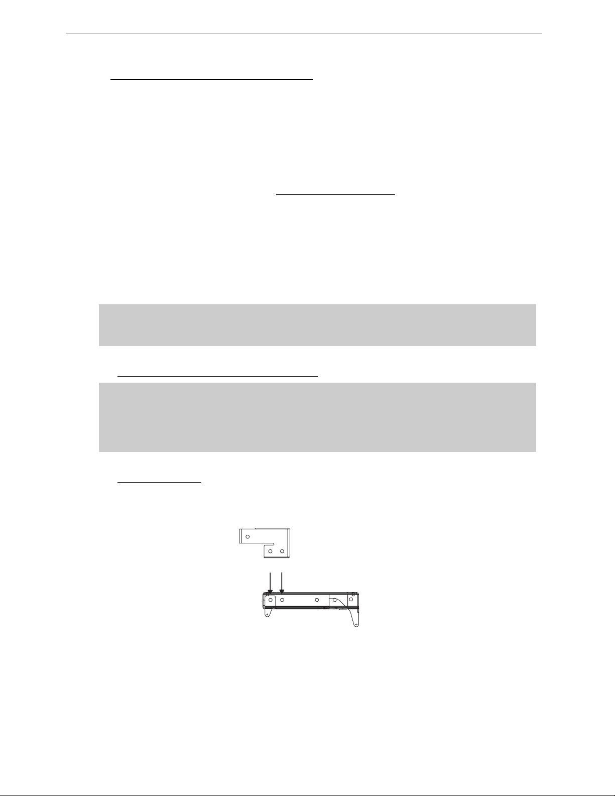
Page 32/97 GEO D RIGGING PROCEDURE
5.4 GEO D Cluster Flying Setup (1 motor)
Flying a GEO D10 cluster from 1 motor requires the following accessories:
• 1 x Motor properly rated
• 1 x Geo-Bridle (GEO-BRIDLE)
• 1 x GEO D Main Bumper (GEOD-BUMPER)
• 1 x GEO D Short Extension Bar (GEOD-EXBAR1)
• 1 x GEOD Front Extension Bar if strong positive tilt is required
• 1 x GEO D Compression Wheel (GEOD-ORP)
• 1 x GEO D Bottom Bumpe r (GEO D-B TBU MPER )
• 1 x GEO D Chain Lever Hoist (LEVA0750 or LEVA1500)
• 1 x Chain Bag (CHBAG)
• 6 x GEOD push-pins per flown GEO D10 (BLGEOD)
• or 1 x GEOD shoulder bolts and nuts kit for fixed installations per flown GEO D (G EOD-BNFIX)
Motor and chain lever hoist must be rated to support the entire cluster weight.
Please check configurations in Geosoft2 for proper motor and chain lever hoists rating.
(GEOD-EXBAR4)
IMPORTANT
5.4.1 Allowed “One Rigging Point” Configurations
IMPORTANT
- “One rigging point” mode is strictly limited to GeoD clusters (no Geo Sub allowed);
- Maximum GeoD quantity allowed for this mode is 8;
- Compression Wheel and Bridle are designed for Extension Bar EXBAR1 and must not be
used with Extension Bar EXBAR2.
5.4.2 Bumper Assembly
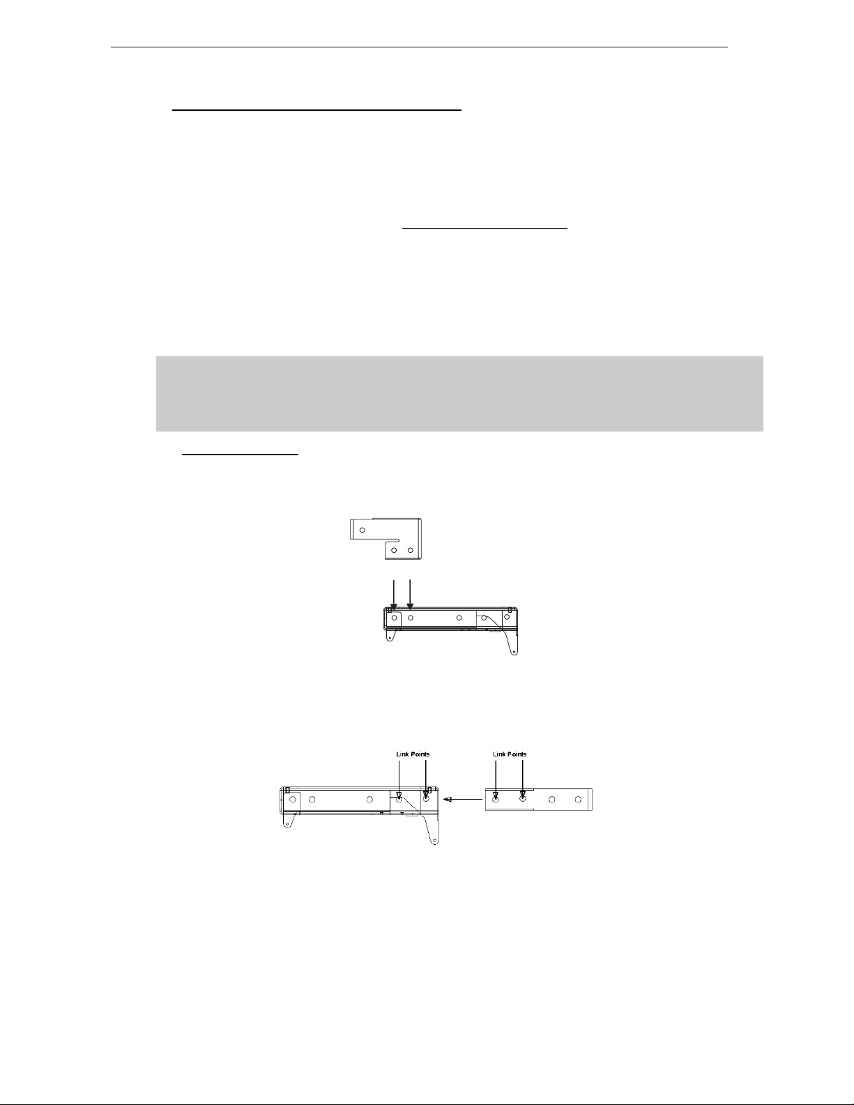
• Strong bumper positive tilt only; connect the Front Extension Bar Bumper through the Link
Points the with the two axes using corresponding holes (see drawing below), and ensure that
these axes are properly locked with supplied “R” clips;
Link Points
LINKING GEOD BUMPER AND EXTENSI ON BAR EXBAR4
Page 33
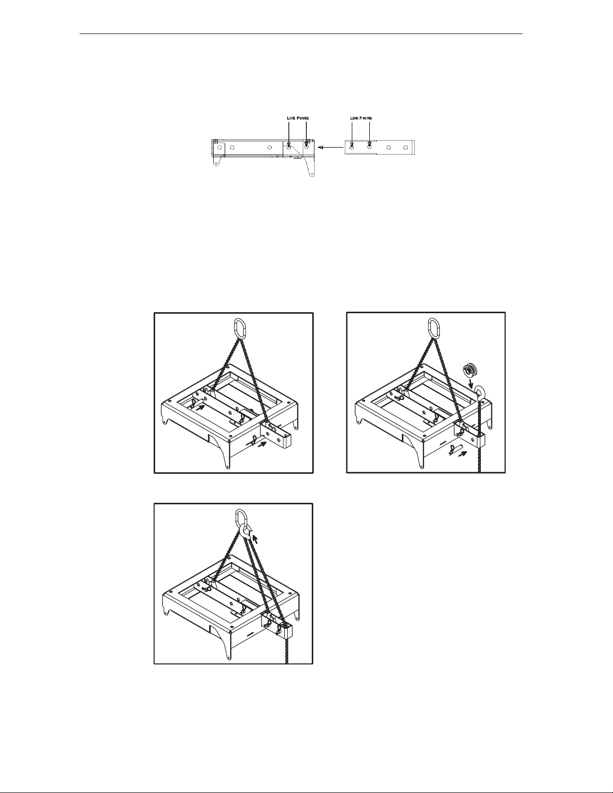
GEO D RIGGING PROCEDURE Page 33/97
• Connect the Short Extension Bar EX1 to the Main Bumper through the Link Points the with the
two axes using corresponding holes (see drawing below), and ensure that these axes are
properly locked with supplied “R” clips;
LINKING GEOD BUMPER AND EXTENSION BAR EXBAR1
• Connect the bridle ring to the motor hoist, the bridle adj ustable leg to the front rigging point and
the bridle fixed length leg to the rear rigging point;
• Attach the chain hook of the LEVA750 or LEVA1500 Chain Lever Hoist to the motor (see drawing
below) after passing the chain through Short Extension Bar EX1 behind rear compression point;
• Install the compression wheel by removing the axis located at compress ion point, inserting the
wheel and setting back the axis in position; ensure that the axis is properly locked with supplied
“R” clip and that chain is properly located behind the axis;
• Lift the bumper assembly so that top GeoD can be connected at convenient height.
CONNECTING MOTOR, BRIDLE, WHEL AND CHAIN LEVEL HOIST
Page 34
Page 34/97 GEO D RIGGING PROCEDURE
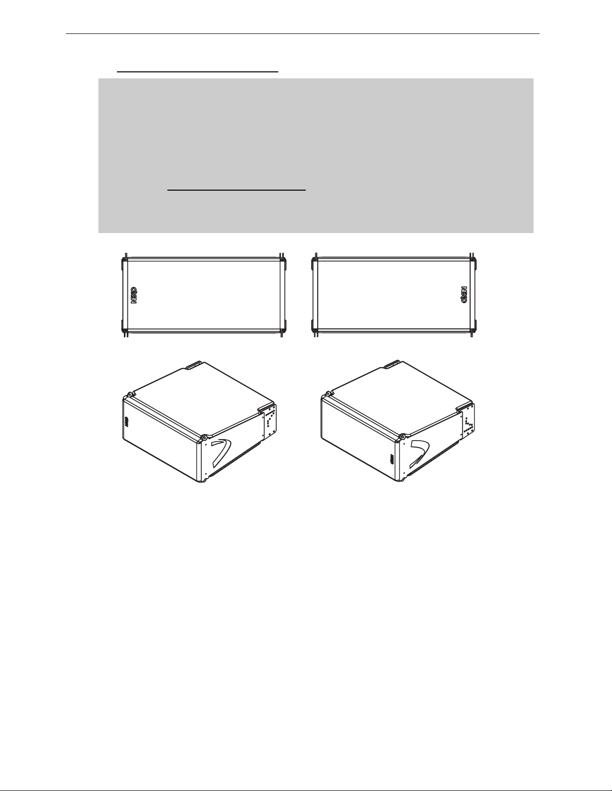
5.4.3 Bumper to first GEO D10 assembly
IMPORTANT
GEO D10 can be flown “Left” or “Right” :
- “Left” means Nexo logo on front grid is left as seen from front;
- “Right” means Nexo logo on front grid is right as seen from front.
GEO D10 can be connected to bumper “Left” or “Right” by simply flip ping the cabinets
upside down: do not reverse rigging plates
Whenever possible, NEXO recommends symmetrical designs (preferably NEXO logo
inwards in stereo configurations)
‘’LEFT’’ CONFIGURATION ’’RIGHT’’ CONFIGURATION
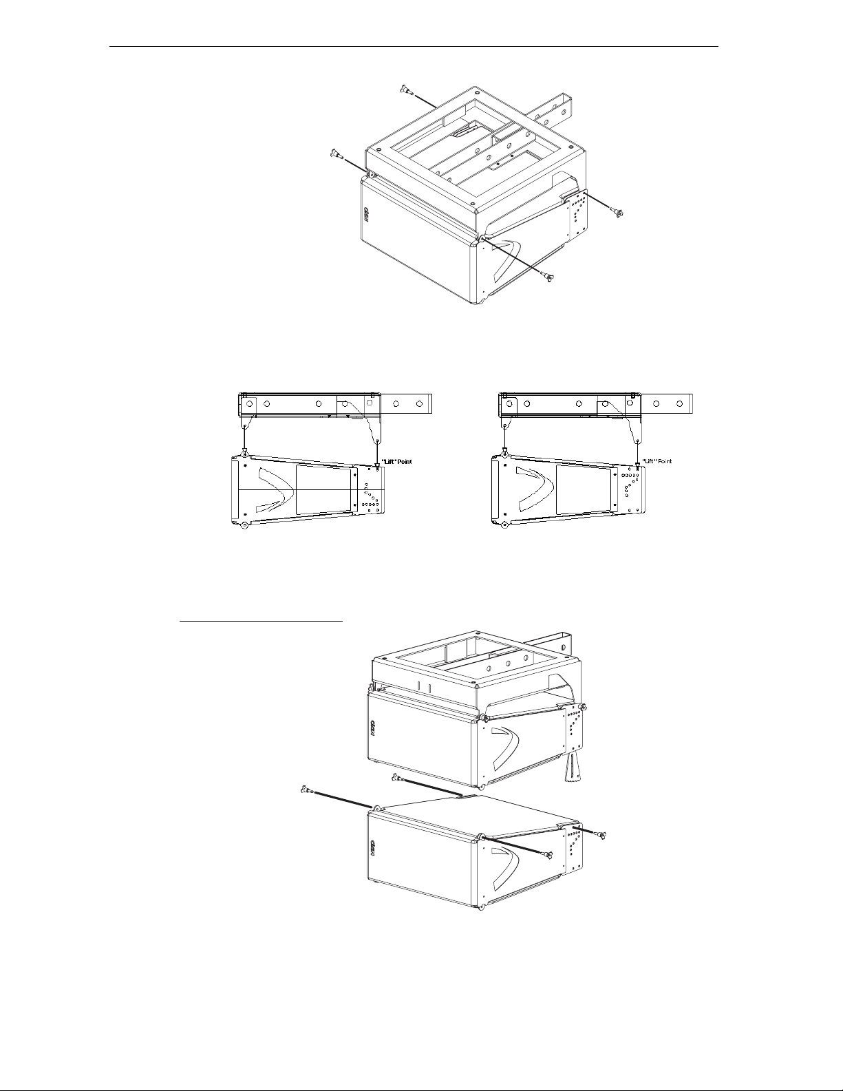
4 push-pins (BLGEOD, 10mm diameter x 20 mm length) connect the top GEO D10 to the bumper.
• Position the bumper on the fi rst GEO D10 by lifting or lowering bumper assembly with motor
hoist;
• Link the GEO D10 to the bumper assembly using the four 10mm x 20mm push-pins; front
bumper connects at GEO D10 front articulation point, rear bumper connects at “LIFT” GEO D10
rigging plates holes;
• Check that all push-pins are in their locked position.
• Ensure that n o objects have been placed acci dentally on the top of the bumper as t hey may fall
when the sys te m is lif te d.
Page 35
GEO D RIGGING PROCEDURE Page 35/97
FIRST GEO D10 TO BUMPER ASSEMBLY
“RIGHT“ CONFIGURATION “LEFT“ CONFIGURATION
5.4.4 First to second GEO D 10
FIRST TO SECOND GEO D10
Page 36
Page 36/97 GEO D RIGGING PROCEDURE
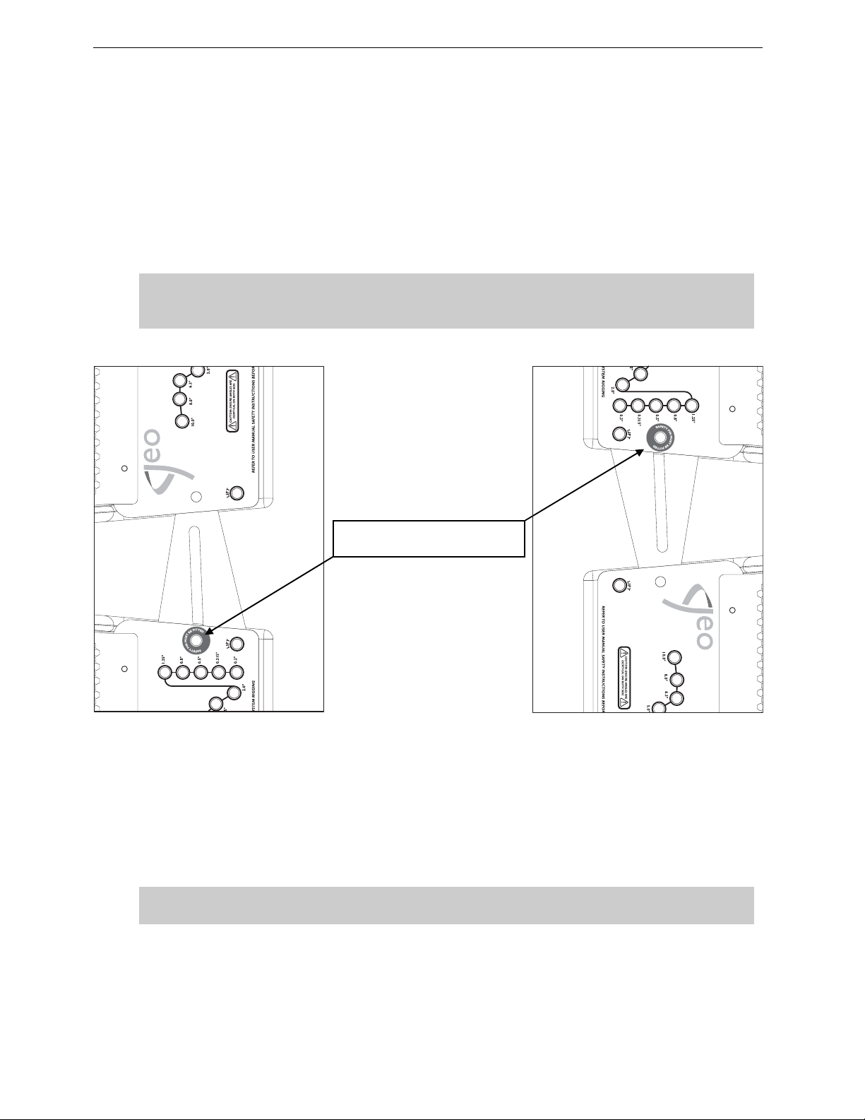
4 push-pins (BLGEOD, 10mm diameter x 20 mm length) connect first to second GEO D10, 2 additional
push pins-are required for angle adjustment.
• Lift bumper and top GEO D10 assembly, and position the next GEO D10 below the assembly,
with NEXO logo on the same side than the upper cabinet.
• Lo wer bumper and top GEO D10 assembly carefully until the first and sec ond GEO D10 side
rigging plates locate. Use front grid, rear vent ports or handle to g uide the ass embly. The rigging
plates have been designed to locate against each other and so align the holes correctly.
• Connect the upper GEO D link bar to the lower GEO D rigging plate (or lower link b ar to upper
rigging plate for “Right” configuration) by inserting one 10mm x 20 mm push-pin in the “SAFE TY
PIN MUST BE FITTED” hole on each side (see figure below).
IMPORTANT
The push-pins for “SA FETY PIN MUS T BE FITT ED” holes must always be inserte d first and
stay in position permanently. NEVER REMOVE THEM ONCE CABINETS ARE SUSPENDED.
« SAFETY PIN MUST BE FITTED »
HOLE
• Insert two additional 10mm x 20mm push-pins in the front holes (see figure above).
• Lift the bumper and two first GEO D10’s to a height that allows convenient acc ess to the linking
bars and the angle setting holes.
• Insert 1 additonal push-pin to the required angle value hole on each side
• Check that all 6 push-pins are locked.
IMPORTANT
Ensure angle settings are identical on both sides of the cabinet.
Page 37
GEO D RIGGING PROCEDURE Page 37/97
5.4.5 Subsequent GEO D10’s
• Repeat the above section steps, until all GEO D10’s are in place. As the assembly is lifted,
angles between GEO D10’s cabinets will remain at 0° whatever the linking bar position s.
• NB : angle set tings are free to b e adjust ed while the s ystem is c lear of the ground, pr ovided that
rear pull-up force is not applied.
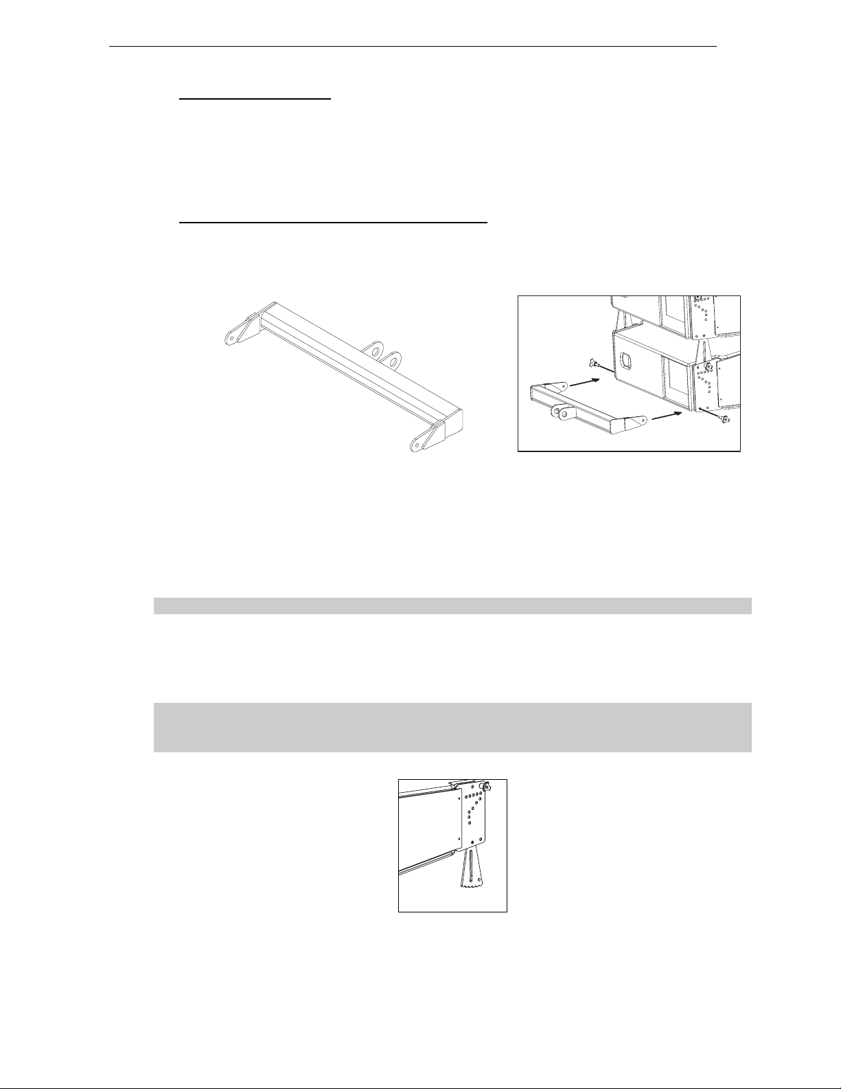
5.4.6 Applying compression with the Chain Lever Hoist
• Once the GEO D10 assembly is completed, connect the bottom bumper to the last GEO D10
with the 10mm x 20mm push-pins inserted in the “FIX” bottom hole (se e drawings below ).
• Check the array according to the Checklist procedure described later in this manual.
• Attach the main hook of the Chain Lever Hoist to the rear of the Bottom Bumper;
• Manually raise the Bottom Bumper and rotate the fingerwheel clockwise until the chain is taught;
• Make a final check that the Chain Lever Hoist is correctly installed;
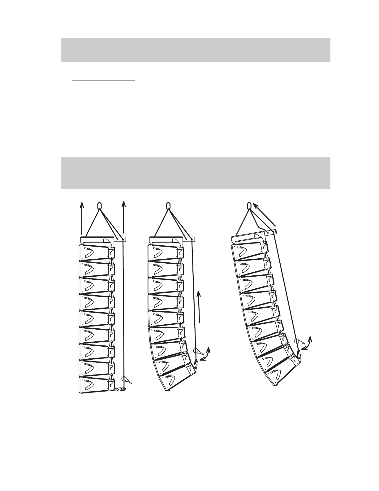
• Rotate the lever to apply the pull-up force to the bottom of the array; notice that, as the chain gets
shorter, the cabinets in the array close together to the angles set by the angle adjustments pushpins;
As the chainload tensions, ensure that no twisting occurs on the chain;
• Once all of the cabinets are closed together, continuing rotating the lever will tilt the bumper
down;
• store the surplus chain in the chain bag supplied. The chain bag should be clipped to the chain.
In case of “Left” configuration, make sure that the bottom link bars cannot hurt anyone
going below the cluster. If any doubt, NEXO strongly recomme nds removing them
(screws can be replaced by 10mm x 20mm push-pins to facilitate such change).
BOTTOM LINK BAR TO BE REMOVED FROM “LEFT” CLUST ER S CONFI GUR A TION
Page 38
Page 38/97 GEO D RIGGING PROCEDURE
IMPORTANT
DO NOT attempt to make any changes to the angle adjustements when the compression
pull-up force is applied.
5.4.7 Positioning the cluster
• Adjust the bumper angl e as determined in GeoSoft2 by rotating the lever from the bottom of the
cluster ;
• Check all GEO D angles with an inclinometer;
• Lift the GEO D array to the height determined in GeoSoft2 (GeoSoft2 array height definition is for
the top edge of the topmost cabinet);
• Once the bumper is in definitive posit ion a secondary safety steel must be fitted (this secondary
safety steel should link the bumper to a suitable point in the supporting structure);
IMPORTANT
The requirements for secondary safety systems vary with territories. However, the
secondary safety steel MUST have a SWL equivalent to or greater than that of the rigging
system.
APPLYING COMPRESSION AND SET TIN G BUM P ER AN GLE
Page 39

GEO D RIGGING PROCEDURE Page 39/97
5.4.8 De-rigging and loading out
Taking the system down is just a case of doing the reverse procedure to flying the array. However,
there are so me important factors to consider.
• Lower the array until the bottom cabinet is just off the floor;
• Rotate the chain hoist lev er counter-clockwise until bumper is back t o horizontal position and no
tension is applied on the GEO D compression chain.
• Disconnect the bottom GEO D from the bottom bumper and remove the bottom bumper from the
array.
Link cables must be disconnected and stowed away in the recesses in the rear of each
cabinet.
• NB : As the system is lowered it is good practise to disconnect as many loudspeaker cables as
can be reached without climbing the array. This ensures that a cable should not be accidentally
forgotten when the system is separated. Damage to the connector will occur should this mistake
be made.
• Angle adjustment push- pins should be removed from the angle setting and insert ed in the “FIX”
hole so that Geo D’s sit flat on the dolly .
• Lift the dolly manually below the array and connect it to the bottom GEO D with 4 push-pins.
Carefully lower the array so that the dolly being on the ground is not b eing sub mitted t o
the entire cluster weight.
• Disconnect the first block of 3 GEO D’s at the connection between 3rd and 4th bottom cabinets.
• Carefully lift the array until the array is clear. Ensure the array is vertical at all times.
• Repeat the procedure for all cabinets.
• Remove the GEO D compression chain from the GEO D extension bar, slide the extension bar
into the bumper and remember to replace all the axes back in their respective beams.
Page 40
Page 40/97 GEO D RIGGING PROCEDURE
5.4.9 Rigging and De-rigging with GEOD Dolly Storage Tray
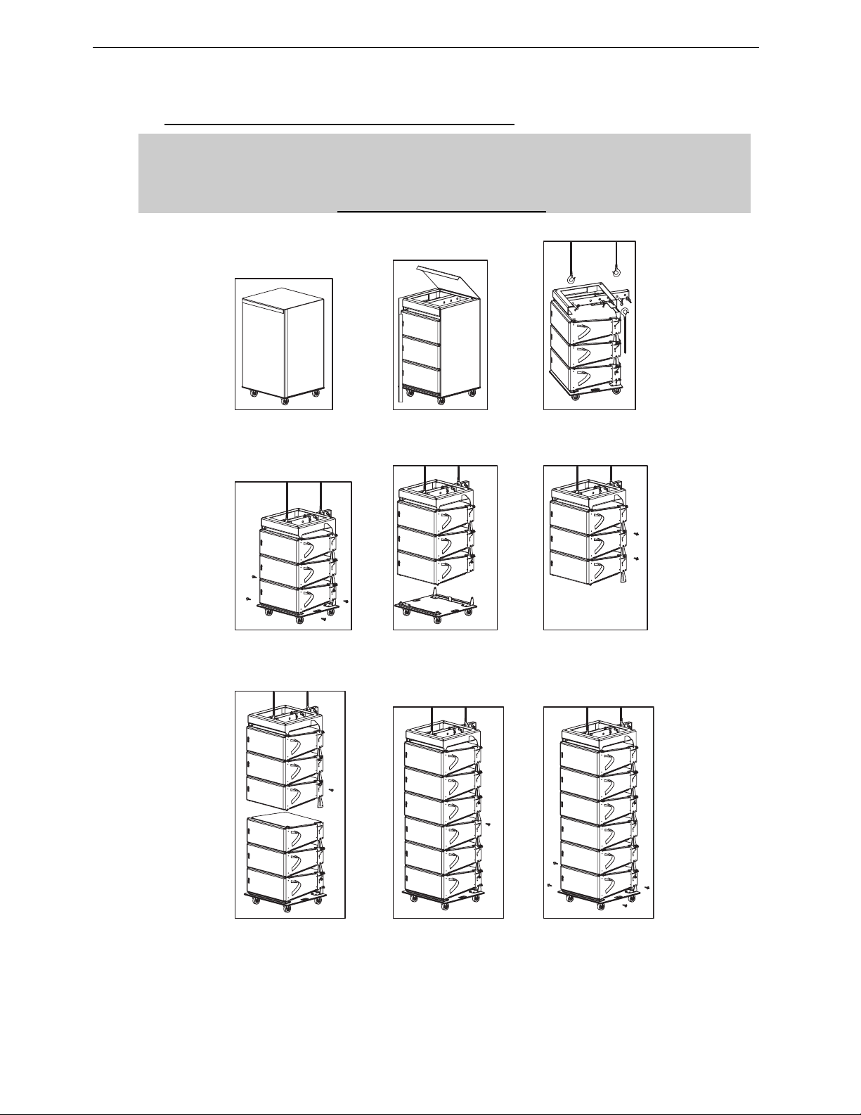
IMPORTANT
GEOD Dolly Storage Tray are designed for 3 or 4 GEO D’s + bumper or case ;
GEOSUB Dolly Storage Tray is designed for up to 2 GEO SUB’s + bumper or case.
Never exceed these quantities.
FROM PACKAGED TO FLOWN GEO D10’S
Page 41
GEO D RIGGING PROCEDURE Page 41/97
5.5 GEO D Cluster Flying Setup (2 motors)
Flying a GEO D10 cluster from 2 motors requires the following accessories:
• 2 x Motors properly rated
• 1 x GEO D Main Bumpe r (G EOD- BU MPER )
• 1 x GEO D Short Extension Bar (GEOD-EXBAR1)
• 1 x GEOD Front Extension Bar if strong positive tilt is required
(GEOD-EXBAR4)
• 1 x GEO D Bottom Bu mpe r (G EOD -BT BUM PER )
• 1 x GEO D Chain Lever Hoist (LEVA0750 or LEV A1500)
• 1 x Chain Bag (CHBAG)
• 6 x GEOD push-pins per flown GEO D10 (BLGEOD)
• or 1 x GEOD shoulder bolts and nuts kit for fixed installations per flown GEO D (GEOD-BNFIX)
IMPORTANT
Each of front, rear motor and chain lever hoists must be rated to support the entire
cluster weight.
Please check configurations in Geosoft2 for proper mo tor and chain lever hoists rating
5.5.1 Bumper Assembly
• Strong bumper positive tilt only; connect the Front Extension Bar Bumper through the Link
Points the with the two axes using corresponding holes (see drawing below), and ensure that
these axes are properly locked with supplied “R” clips;
Link Points
LINKING GEOD BUMPER AND EXTENSION BAR EXBAR4
• Connect the Short Extension Bar EX1 to the Main Bumper through the Link Points the with the
two axes using corresponding holes (see drawing below), and ensure that these axes are
properly locked with supplied “R” clips;
LINKING GEOD BUMPER AND EXTENSIO N BA R EX1
• Link the motor hoists to the Bumper – Extension Bar assembly to Front and Rear R igging Points
with the two axes using corresponding holes (see drawing below), and ensure that t hese axes
are properly locked with supplied “R” clips;
• Attach the chain hook of the LEVA500 or LEVA1500 Chain Lever Hoist to the Compression Point
(see drawing below).
Page 42
Page 42/97 GEO D RIGGING PROCEDURE
CONNECTING FRONT, REAR MOTORS AND CHAIN LEVEL HOIST
5.5.2 Bumper to first GEO D10 assembly
IMPORTANT
GEO D10 can be flown “Left” or “Right” :
- “Left” means Nexo logo on front grid is left as seen from front;
- “Right” means Nexo logo on front grid is right as seen from front.
GEO D10 can be connected to bumper “Left” or “Right” by simply flip ping the cabinets
upside down: do not reverse rigging plates
Whenever possible, NEXO recommends symmetrical designs (preferably NEXO logo
inwards in stereo configurations)
‘’LEFT’’ CONFIGURATION ’’RIGHT’’ CONFIGURATION
4 push-pins (BLGEOD, 10mm diameter x 20 mm length) connect the top GEO D10 to the bumper.
Page 43
GEO D RIGGING PROCEDURE Page 43/97
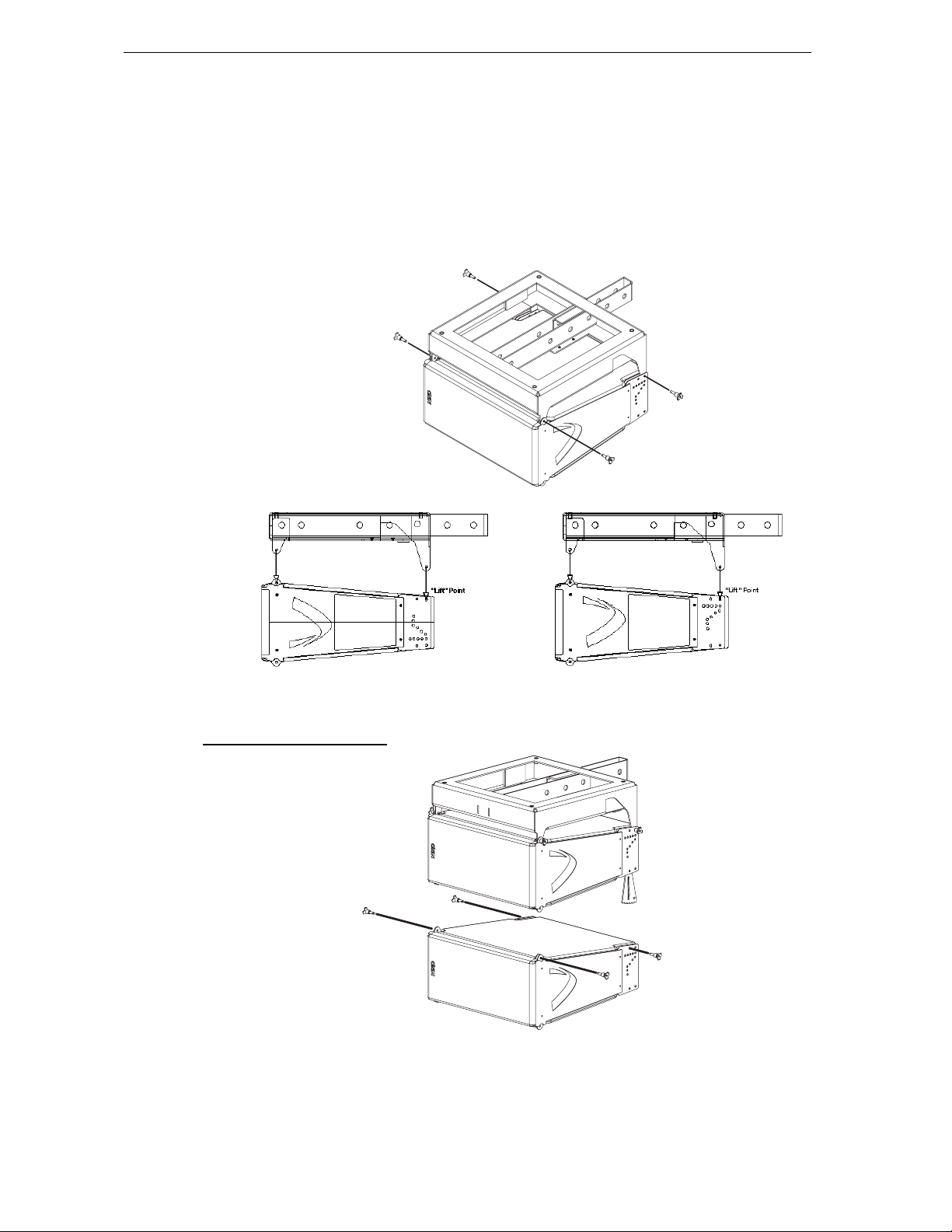
• Position the bumper on the first GEO D10 by lifting or lowering bumper assembly with motor
hoists;
• Link the GEO D10 to the bumper assembly using the four 10mm x 20mm push-pins; front
bumper connects at GEO D10 front articulation point, rear bumper connects at “LIFT” GEO D10
rigging plates holes;
• Check that all push-pins are in their locked position.
• Ensure t hat no objects have been placed ac cidentally on the top of the bumper as they may fall
when the system is lif ted.
FIRST GEO D10 TO BUMPER ASSEMBLY
“RIGHT“ CONFIGURATION “LEFT“ CONFIGURATION
5.5.3 First to second GEO D 10
FIRST TO SECOND GEO D10
Page 44
Page 44/97 GEO D RIGGING PROCEDURE
4 push-pins (BLGEOD, 10mm diameter x 20 mm length) connect first to second GEO D10, 2 additional
push pins-are required for angle adjustment.
• Lift bumper and top GEO D10 assembly, and position the next GEO D10 below the assembly,
with NEXO logo on the same side than the upper cabinet.
• Lo wer bumper and top GEO D10 assembly carefully until the first and sec ond GEO D10 side
rigging plates locate. Use front grid, rear vent ports or handle to guide t he ass embly. The rigging
plates have been designed to locate against each other and so align the holes correctly.
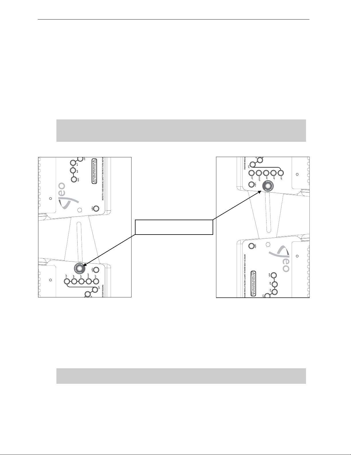
• Connect the upper GEO D link bar to the lower GEO D rigging plate (or lower link b ar to upper
rigging plate for “Right” configuration) by inserting one 10mm x 20 mm push-pin in the “SAFE TY
PIN MUST BE FITTED” hole on each side (see figure below).
IMPORTANT
The push-pins for “SA FETY PIN MUS T BE FITT ED” holes must always be inserte d first and
stay in position permanently. NEVER REMOVE THEM ONCE CABINETS ARE SUSPENDED.
« SAFETY PIN MUST BE FITTED »
HOLE
• Insert two additional 10mm x 20mm push-pins in the front holes (see figure above).
• Lift the bumper and two first GEO D10’s to a height that allows convenient acc ess to the linking
bars and the angle setting holes.
• Insert 1 additonal push-pin to the required angle value hole on each side
• Check that all 6 push-pins are locked.
IMPORTANT
Ensure angle settings are identical on both sides of the cabinet.
Page 45
GEO D RIGGING PROCEDURE Page 45/97
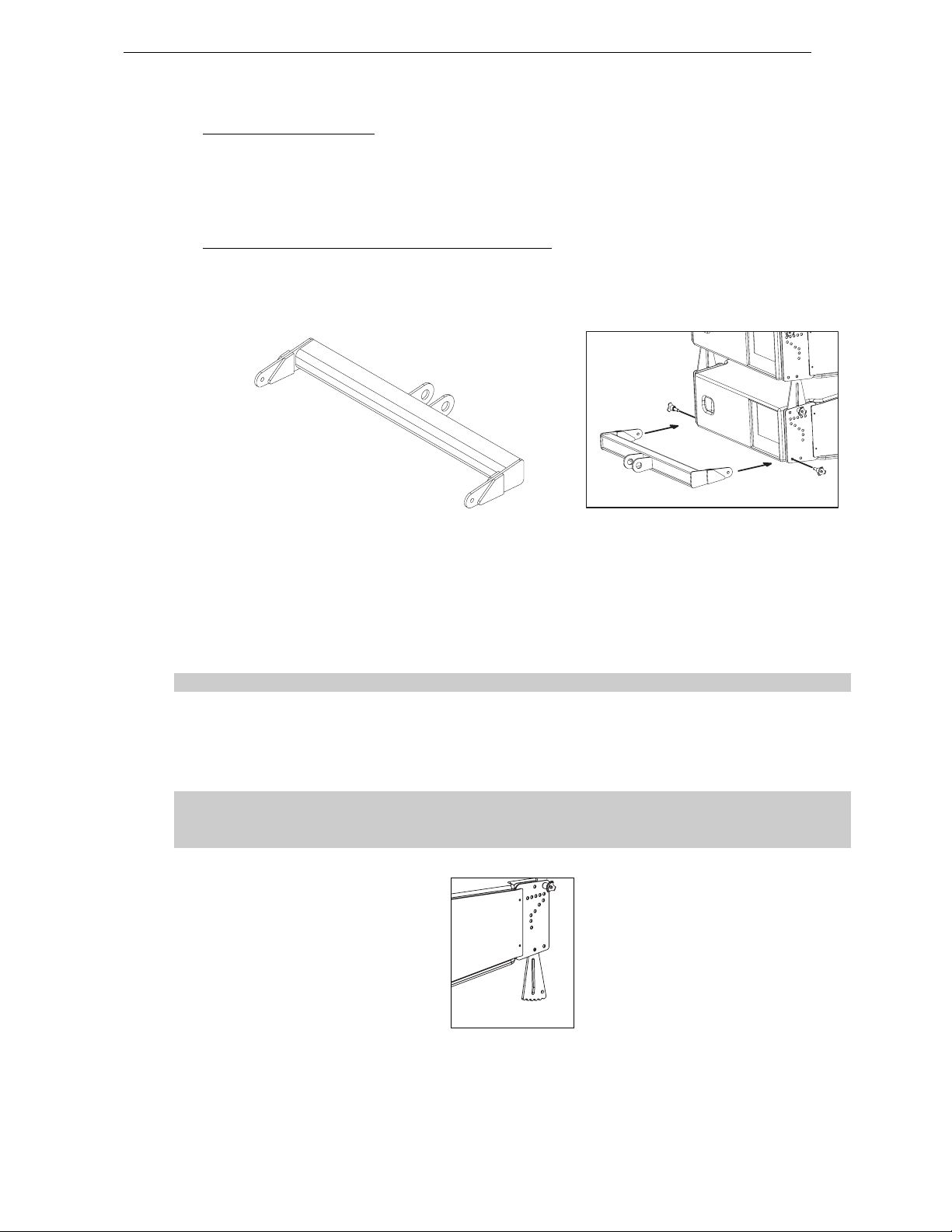
5.5.4 Subsequent GEO D10’s
• Repeat the above section steps, until all GEO D10’s are in place. As the assembly is lifted,
angles between GEO D10’s cabinets will remain at 0° whatever the linking bar position s.
• NB : angle set tings are free to b e adjust ed while the s ystem is c lear of the ground, pr ovided that
rear pull-up force is not applied.
5.5.5 Applying compression with the Chain Lever Hoist
• Once the GEO D10 assembly is completed, connect the bottom bumper to the last GEO D10
with the 10mm x 20mm push-pins inserted in the “FIX” bottom hole (se e drawings below ).
• Check the array according to the Checklist procedure described later in this manual.
• Attach the main hook of the Chain Lever Hoist to the rear of the Bottom Bumper;
• Manually raise the Bottom Bumper and rotate the fingerwheel clockwise until the chain is taught;
• Make a final check that the Chain Lever Hoist is correctly installed;
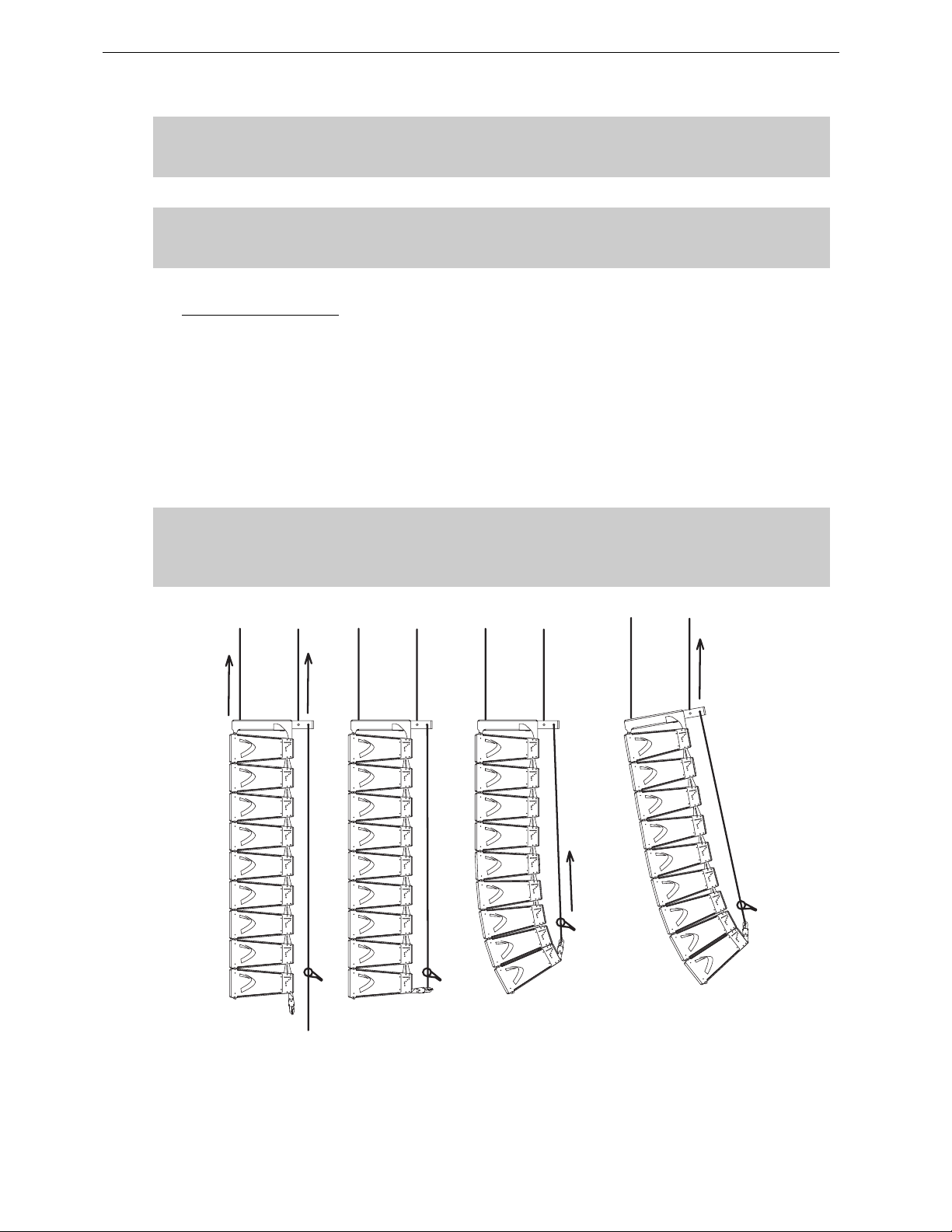
• Rotate the lever to apply the pull-up force to the bottom of the array; notice that, as the chain gets
shorter, the cabinets in the array close together to the angles set by the angle adjustments pushpins;
As the chainload tensions, ensure that no twisting occurs on the chain;
• When all of the cabinets are closed together, required force to rotate the lever becom es much
stronger. This is the indication that the an gles have been correctly set;
• store the surplus chain in the chain bag supplied. The chain bag should be clipped to the chain.
In case of “Left” configuration, make sure that the bottom link bars cannot hurt anyone
going below the cluster. If any doubt, NEXO strongly recomme nds removing them
(screws can be replaced by 10mm x 20mm push-pins to facilitate such change).
BOTTOM LINK BAR TO BE REMOVED FROM “LEFT” CLUST ER S CONFI GUR A TION
Page 46
Page 46/97 GEO D RIGGING PROCEDURE
IMPORTANT
DO NOT attempt to force on LEVA750 or LEVA1500 lever once you feel it resisting
strongly to rotation; you might damage GEO D flying system by doing so.
IMPORTANT
DO NOT attempt to make any changes to the angle adjustements when the compression
pull-up force is applied.
5.5.6 Positioning the cluster
• Lift the GEO D array to the height determined in GeoSoft (GeoSoft array height definition is for
the top surface of the topmost cabinet);
• Adjust the bumper angle as determined in GeoSoft by lowering or lifting rear motor hoist (so that
the front height does not change);
• Check all GEO D angles with an inclinometer;
• Once the bumper is in definitive posit ion a secondary safety steel must be fitted (this secondary
safety steel should link the bumper to a suitable point in the supporting structure);
IMPORTANT
The requirements for secondary safety systems vary with territories. However, the
secondary safety steel MUST have a SWL equivalent to or greater than that of the rigging
system.
APPLYING COMPRESSION AND SET TIN G BUM P ER AN GLE
Page 47

GEO D RIGGING PROCEDURE Page 47/97
5.5.7 De-rigging and loading out
Taking the system down is just a case of doing the reverse procedure to flying the array. However,
there are so me important factors to consider.
• Lower the array running the two motor hoists simultaneously until the bottom cabinet is just off
the floor, main bumper being horizontal.
• Rotate the chain hoist lever counter-clockwise until there is no tension on the GEO D
compression chain and no compression on the system.
• Disconnect the bottom GEO D from the bottom bumper and remove the bottom bumper from the
array.
Link cables must be disconnected and stowed away in the recess es in the r ea r of eac h
cabinet.
• NB : As the system is lowered it is good practise to disconnect as many loudspeaker cables as
can be reached without climbing the array. This ensures that a cable should not be accidentally
forgotten when the system is separated. Damage to the connector will occur should this mistake
be made.
• Angle adjustment push- pins should be removed from the angle setting and insert ed in the “FIX”
hole so that Geo D’s sit flat on the dolly .
• Lift the dolly manually below the array and connect it to the bottom GEO D with 4 push-pins.
Carefully lower the array so that the dolly being on the ground is not b eing sub mitted t o
the entire cluster weight.
• Disconnect the first block of 3 GEO D’s at the connection between 3rd and 4th bottom cabinets.
• Carefully lift the array using both motor hoists until the array is c lear. Ensure the array is vertical
at all times.
• Repeat the procedure for all cabinets.
• Remove the GEO D compression chain from the GEO D extension bar, slide the extension bar
into the bumper and remember to replace all the axes back in their respective beams.
Page 48
Page 48/97 GEO D RIGGING PROCEDURE
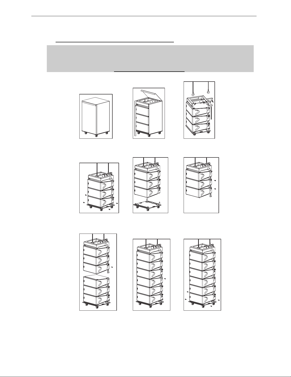
5.5.8 Rigging and De-rigging with GEOD Dolly Storage Tray
IMPORTANT
GEOD Dolly Storage Tray are designed for 3 or 4 GEO D’s + bumper or case ;
GEOSUB Dolly Storage Tray is designed for up to 2 GEO SUB’s + bumper or case.
Never exceed these quantities.
FROM PACKAGED TO FLOWN GEO D10’S
Page 49
GEO D RIGGING PROCEDURE Page 49/97
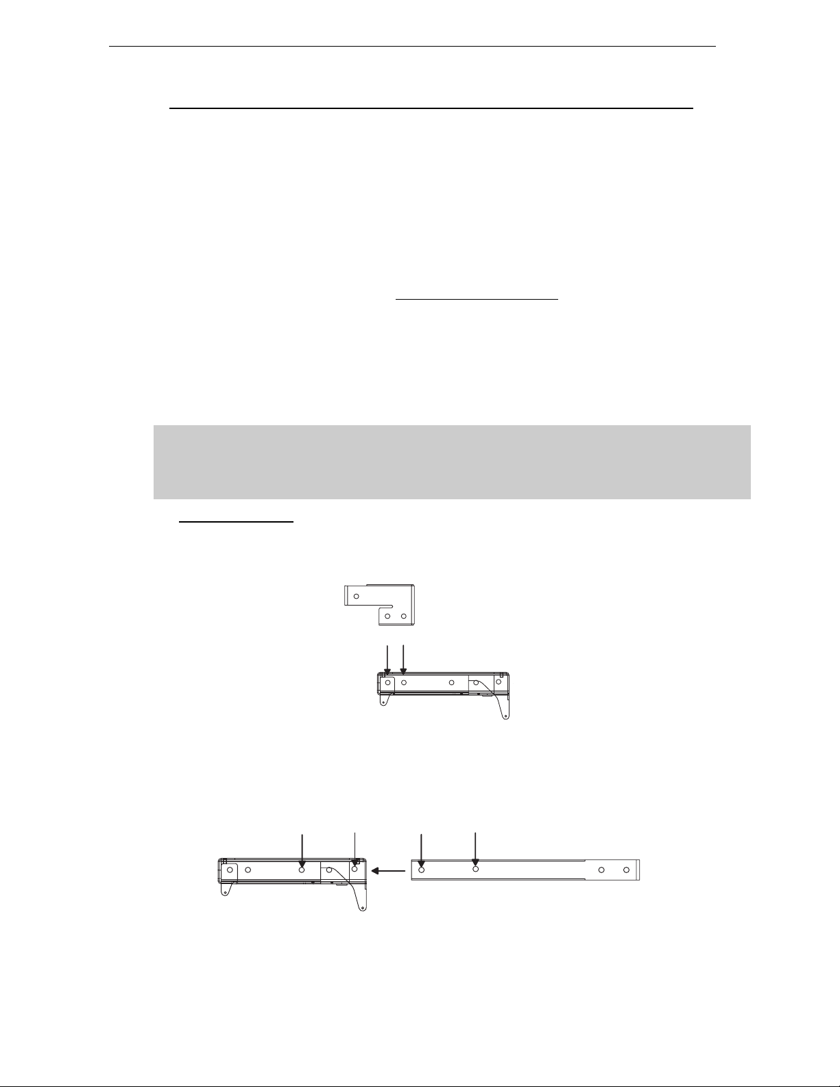
5.6 GEO SUB – GEO D Combined Cluster Flying Setup (2 motors required)
Flying a GEO SUB – GEO D combined cluster is very similar to what has been described in the
above section, except a long Extension Bar EX2 (instead of EX1) is required to extend top
compression point because of GEO SUB depth.
However, the section below details all steps to be com pleted for a safe setup.
Flying a combined GEO D10 / GEO SUB cluster requires:
• 2 x Motors properly rated
• 1 x GEO D Main Bumpe r (G EOD- BU MPER )
• 1 x GEO D long Extension Bar (GEOD-EXBAR2)
• 1 x GEOD Front Extension Bar if strong positive tilt is required
(GEOD-EXBAR4)
• 1 x GEO D Bottom Bu mpe r (G EOD -BT BUM PER )
• 1 x GEO D Chain Lever Hoist (LEVA0750 or LEV A1500)
• 1 x Chain Bag (CHBAG)
• 6 x GEOD push-pins per flown GEO SUB (BLGEOD)
• or 1 x GEOD shoulder bolts and nuts kit for fixed installations per flown GEO D (GEOD-BNFIX)
IMPORTANT
Each of front, rear motor and chain lever hoists must be rated to support the entire
cluster weight.
Please check configurations in Geosoft2 for proper mo tor and chain lever hoists rating
5.6.1 Bumper Assembly
• Strong bumper positive tilt only; connect the Front Extension Bar Bumper through the Link
Points the with the two axes using corresponding holes (see drawing below), and ensure that
these axes are properly locked with supplied “R” clips;
• Connect the Long Extension Bar to the Main Bumper through t he Link Points the with the two
axes using corresponding holes (see drawing below), and ensure that t hese axes are properly
locked with supplied “R” clip s;
Link Points
LINKING GEOD BUMPER AND EXTENSION BAR EXBAR4
LINK POINTS
LINKING GEOD BUMPER AND EXTENSIO N BA R EX2
LINK POINTS
Page 50
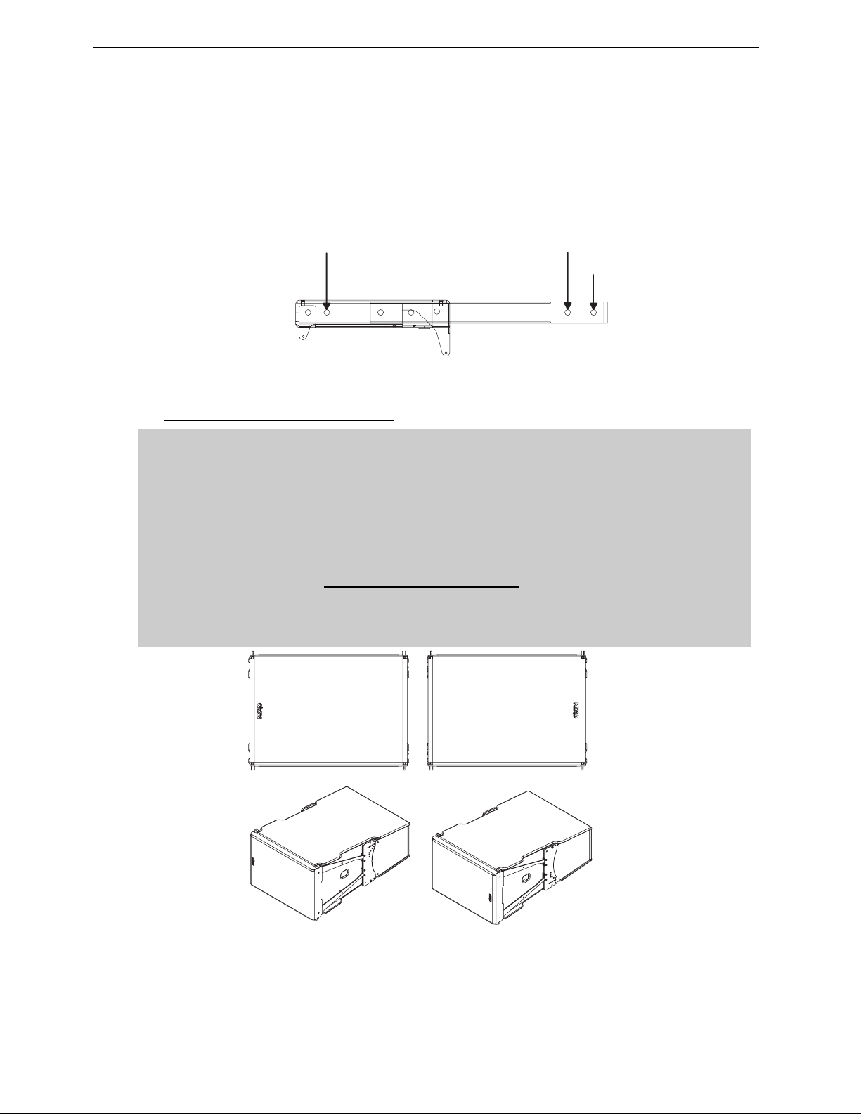
Page 50/97 GEO D RIGGING PROCEDURE
• If strong positive tilt is required, front rigging point as to be extended further; connect the Front
Extension Bar Bumper through the Link Points the with the two axes using corresponding holes
(see drawing below), and ensure that these axes are properly locked with supplied “R” clips;
• Link the motor hoists to the Bumper – Extension Bar assembly to Front and Rear Rigging Points
with the two axes using corresponding holes (see drawi ng below), and ensure that these axes
are properly locked with supplied “R” clips;
• Attach the chain hook of the LEVA750 or LEVA1500 Chain Lever Hoist to the Compression Point
(see drawing below).
FRONT RIGGING
POINT
REAR RIGGING
POINT
COMPRESSION
POINT
CONNECTING FRONT, REAR MOTORS AND CHAIN LEVEL HOIST
5.6.2 Bumper to first GEO SUB assembly
IMPORTANT
GEO D10 and GEO SUB can be flown “Left” or “Right” :
- “Left” means Nexo logo on front grid is left as seen from front;
- “Right” means Nexo logo on front grid is right as seen from front.
GEO D10 and GEO SUB can be connected to bumper “Left” or “Right” by simply flipping
the cabinets upside down: do not reverse rigging plates
Whenever possible, NEXO recommends symmetrical designs (preferably NEXO logo
inwards in stereo configurations)
‘’LEFT’’ CONFIGURATION ’’RIGHT’’ CONFIGURATION
Page 51
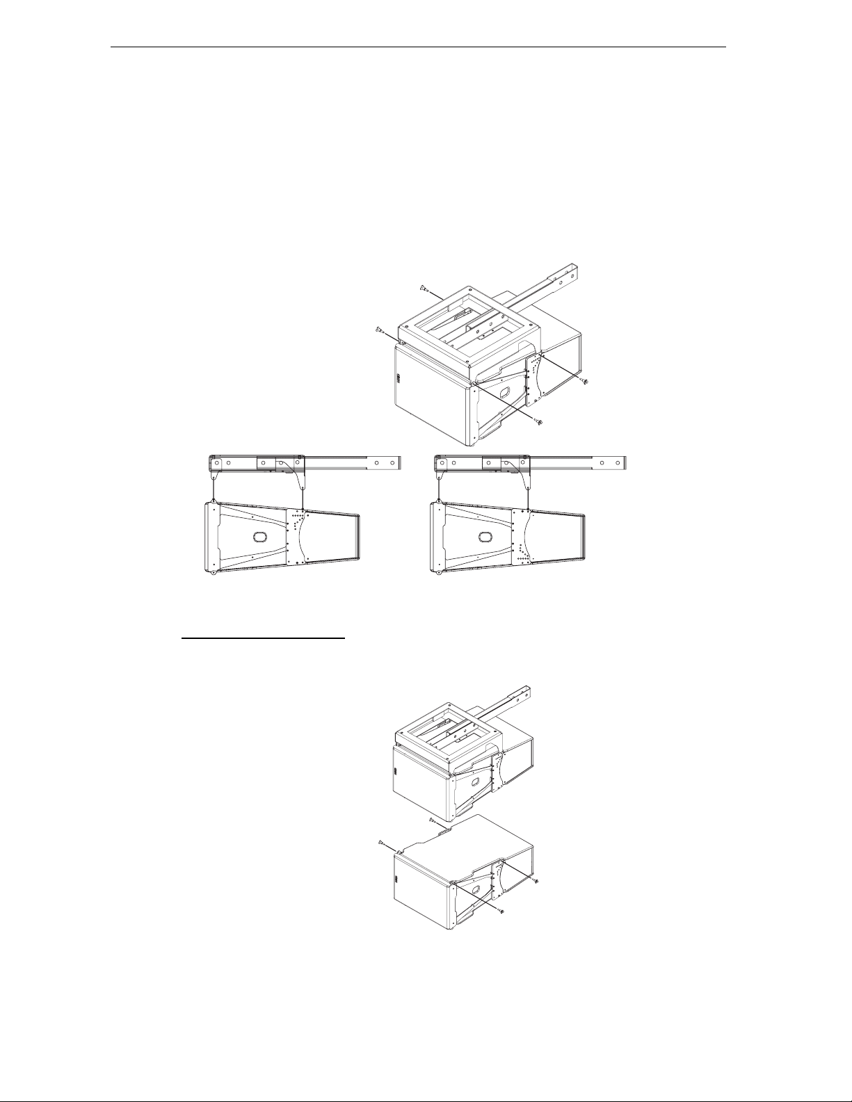
GEO D RIGGING PROCEDURE Page 51/97
"LIFT" POINT
"LIFT" POINT
4 push-pins (BLGEOD, 10mm diameter x 20 mm length) connect the top GEO SUB to the bumper.
• Position t he bumper on the first GEO SUB by lifting or lowering bumper assembly with motor
hoists;
• Link the GEO SUB to the bumper assembly using the four 10mm x 20mm push-pins; front
bumper connects at GEO SUB front articulation point, rear bumper connects at “LIFT” GEO SUB
rigging plates holes;
• Check that all push-pins are in their locked position.
• Ensure t hat no objects have been placed ac cidentally on the top of the bumper as they may fall
when the system is lif ted.
"LIFT" POINT
"LIFT" POINT
FIRST GEO SUB TO BUMPER ASSEMBLY
“LEFT“ CONFIGURATION “RIGHT“ CONFIGURATION
5.6.3 First to second GEO SUB
4 push-pins (BLGEOD, 10mm diameter x 20 mm length) connect first to second GEO S UB, 2 additional
push pins-are required for angle adjustment.
FIRST TO SECOND GEO SUB
Page 52
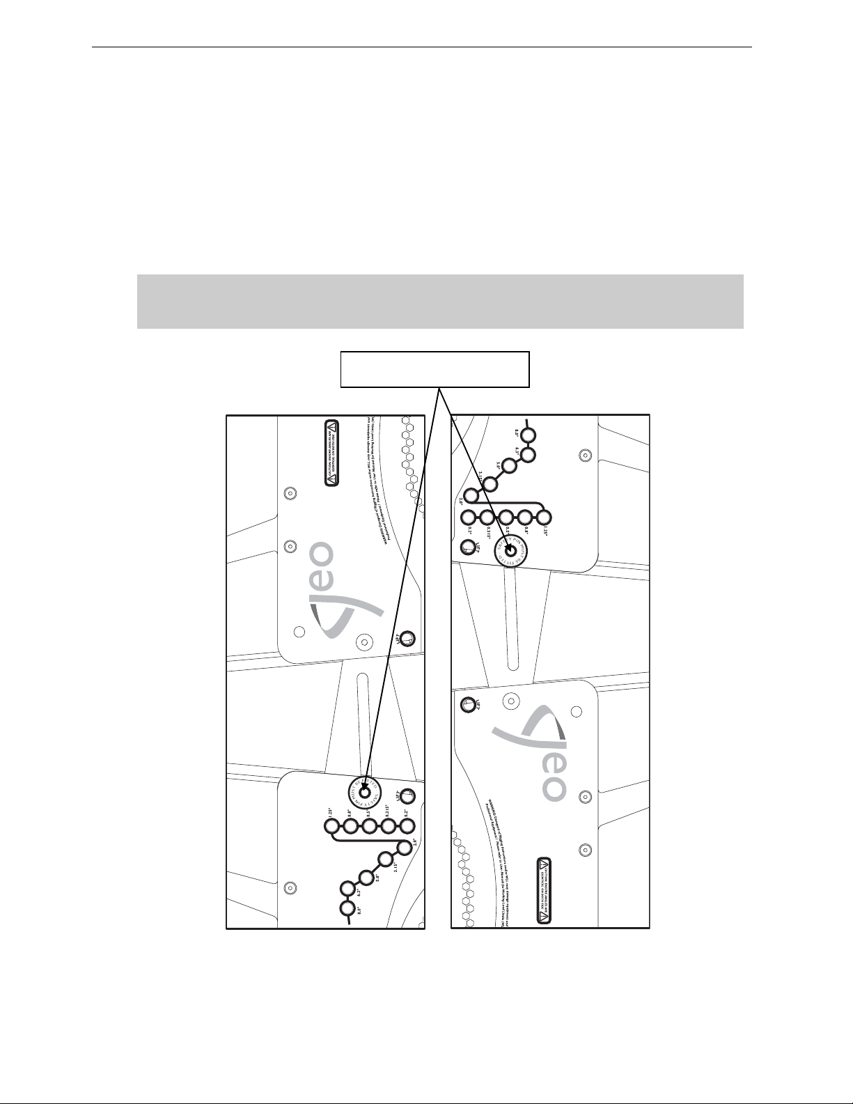
Page 52/97 GEO D RIGGING PROCEDURE
• Lift bumper and top GEO SUB assembly, and position the next GEO SUB below the assembly,
with NEXO logo on the same side than the upper cabinet.
• Lower bumper and top GEO SUB assembly carefully until the first and second GEO SUB side
rigging plates locate. Use front grid, rear vent ports or handle to guide t he ass embly. The rigging
plates have been designed to locate against each other and so align the holes correctly.
• Connect the upper GEO SUB link bar to the lower GEO SUB rigging plate (or lower link bar to
upper rigging plate for “Right” configuration) by inserting one 10mm x 20 mm push-pin in the
“SAFETY PIN MUST BE FITTED” hole on each side (see figure below).
IMPORTANT
The push-pins for “SA FETY PIN MUS T BE FITT ED” holes must always be inserte d first and
stay in position permanently. NEVER REMOVE THEM ONCE CABINETS ARE SUSPENDED.
« SAFETY PIN MUST BE FITTED »
HOLE
Page 53
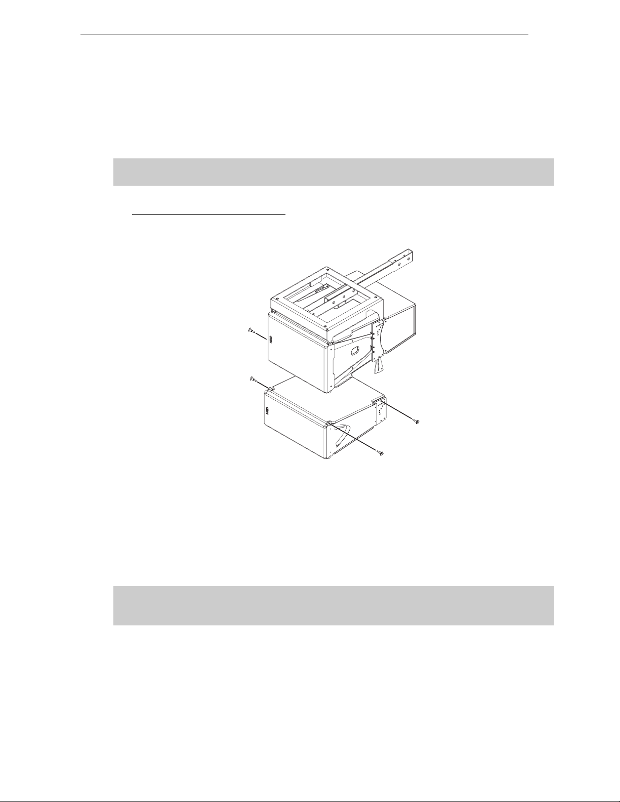
GEO D RIGGING PROCEDURE Page 53/97
• Insert two additional 10mm x 20mm push-pins in the front holes (see figure above).
• Lift the bumper and t wo first GEO SUB’s to a height that allows convenient access to the linking
bars and the angle setting holes.
• Insert 1 additonal push-pin to the required angle value hole on each side
• Check that all 6 push-pins are locked.
IMPORTANT
Ensure angle settings are identical on both sides of the cabinet.
5.6.4 Last GEO SUB to First GEO D10
4 push-pins (BLGEOD, 10mm diameter x 20 mm length) connect first to second GEO S UB, 2 additional
push pins-are required for angle adjustment.
LAST GEO SUB TO FIRST G EO D
• Lift bumper and top GEO SUB ass embly, and position the next GEO SUB below the assembly,
with NEXO logo on the same side than the upper cabinet.
• Lower bumper and top GEO SUB assembly carefully until the GEO SUB and GEO D10 side
rigging plates locate. Use front grid, rear vent ports or handle to guide t he ass embly. The rigging
plates have been designed to locate against each other and so align the holes correctly.
• Connect the upper GEO SUB link bar to the lower GEO D10 rigging plate (or lower link bar t o
upper rigging plate for “Right” configuration) by inserting one 10mm x 20 mm push-pin in the
“SAFETY PIN MUST BE FITTED” hole o n each side (see figure below).
IMPORTANT
The push-pins for “SAFETY PIN MUST BE FITTED” holes must always be inserted first and
stay in position permanently.
• Insert two additional 10mm x 20mm push-pins in the front holes (see figure above).
• Lift t he cluster t o a height t hat allows conveni ent ac cess t o the linking bars and t he an gle set ting
holes.
• Insert 1 additonal push-pin to the required angle value hole on each side
• Check that all 6 push-pins are locked.
Page 54
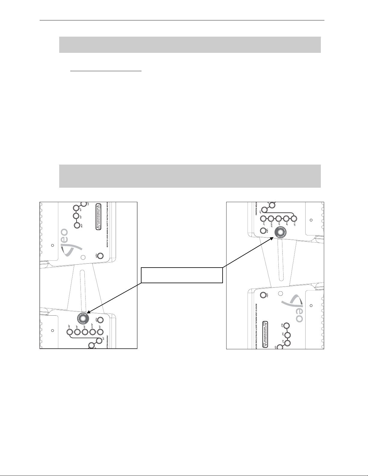
Page 54/97 GEO D RIGGING PROCEDURE
IMPORTANT
Ensure angle settings are identical on both sides of the cabinet.
5.6.5 First to second GEO D 10
4 push-pins (BLGEOD, 10mm diameter x 20 mm length) connect first to second GEO D10, 2 additional
push pins-are required for angle adjustment.
• Lift cluster, and position the next GEO D10 below the assembly, with NEXO logo on the same
side than the upper cabinet.
• Lower cluster carefully until the first and second GEO D10 side rigging plates locate. Use front
grid, rear vent ports or handle to guide the assembly. The rigging pl ates have been designed to
locate against each other and so align the holes correctly.
• Connect the upper GEO D link bar to the lower GEO D rigging plate (or lower link b ar to upper
rigging plate for “Right” configuration) by inserting one 10mm x 20 mm push-pin in the “SAFE TY
PIN MUST BE FITTED” hole on each side (see figure below).
IMPORTANT
The push-pins for “SA FETY PIN MUS T BE FITT ED” holes must always be inserte d first and
stay in position permanently. NEVER REMOVE THEM ONCE CABINETS ARE SUSPENDED.
« SAFETY PIN MUST BE FITTED »
HOLE
• Insert two additional 10mm x 20mm push-pins in the front holes (see figure above).
• Lift t he cluster t o a height t hat allows convenient acc ess to the link ing bars a nd the angle sett ing
holes.
• Insert 1 additonal push-pin to the required angle value hole on each side
• Check that all 6 push-pins are locked.
Page 55
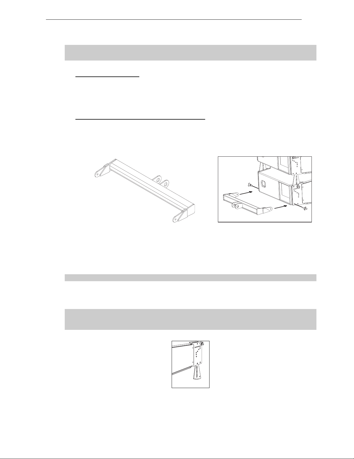
GEO D RIGGING PROCEDURE Page 55/97
IMPORTANT
Ensure angle settings are identical on both sides of the cabinet.
5.6.6 Subsequent GEO D10’s
• Repeat the above section steps, until all GEO D10’s are in place. As the assembly is lifted,
angles between GEO D10’s cabinets will remain at 0° whatever the linking bar position s.
• NB : angle set tings are free to b e adjust ed while the s ystem is c lear of the ground, pr ovided that
rear pull-up force is not applied.
5.6.7 Applying compression with the Chain Lever Hoist
• Once the GEO SUB / GEO D10 assembly is completed, connect the bottom bumper to the
bottom GEO D10 with the 10mm x 20mm push-pins inserted in the “FIX” bottom hole (see
drawings below).
• Check the array according to the Checklist procedure described later in this manual.
• Attach the main hook of the Chain Lever Hoist to the rear of the Bottom Bumper;
• Manually raise the Bottom Bumper and rotate the fingerwheel clockwise until the chain is taught;
• Make a final check that the Chain Lever Hoist is correctly installed;
• Rotate the lever to apply the pull-up force to the bottom of the array; notice that, as the chain gets
shorter, the cabinets in the array close together to the angles set by the angle adjustments pushpins;
As the chainload tensions, ensure that no twisting occurs on the chain;
• When all of the cabinets are closed together, required force to rotate the lever becom es much
stronger. This is the indication that the an gles have been correctly set;
• store the surplus chain in the chain bag supplied. The chain bag should be clipped to the chain.
In case of “Left” configuration, make sure that the bottom link bars cannot hurt anyone
going below the cluster. If any doubt, NEXO strongly recomme nds removing them
(screws can be replaced by 10mm x 20mm push-pins to facilitate such change).
BOTTOM LINK BAR TO BE REMOVED FROM “LEFT” CLUST ER S CONFI GUR A TION
Page 56
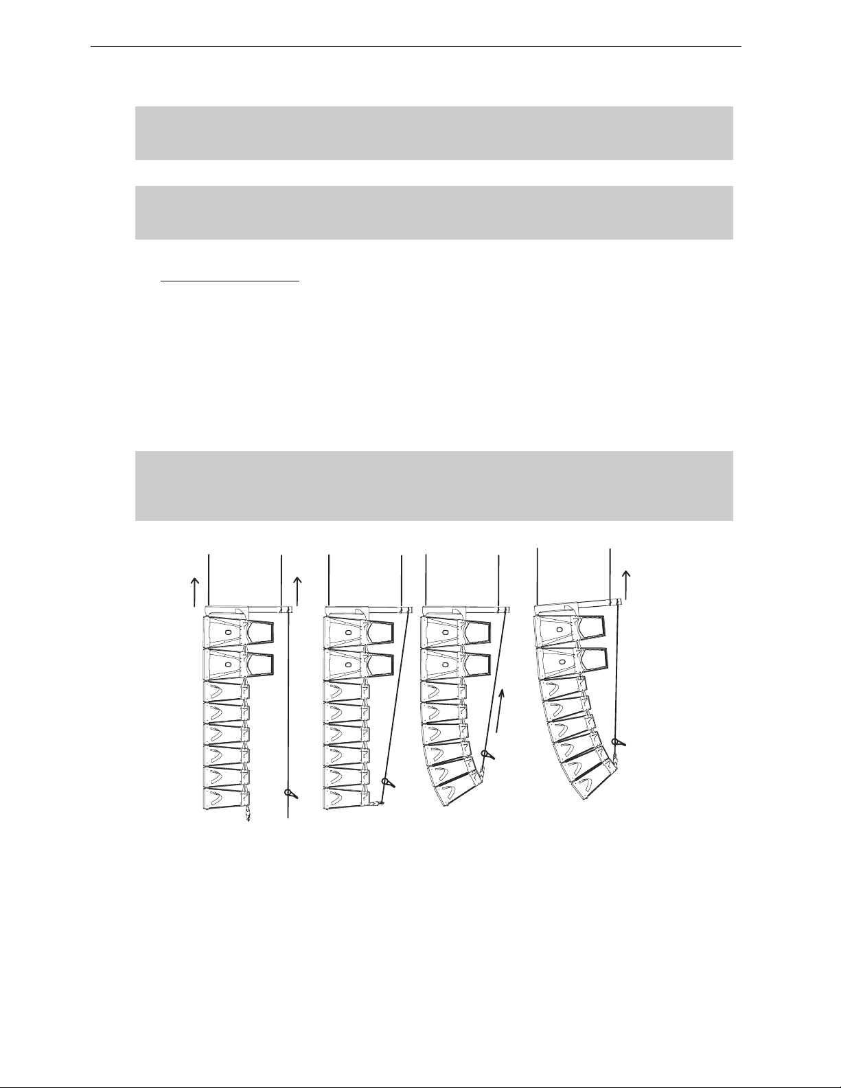
Page 56/97 GEO D RIGGING PROCEDURE
IMPORTANT
DO NOT attempt to force on LEVA750 or LEVA1500 lever once you feel it resisting
strongly to rotation; you might damage GEO D flying system by doing so
IMPORTANT
DO NOT attempt to make any changes to the angle adjustements when the compression
pull-up force is applied.
5.6.8 Positioning the cluster
• Lift the GEO SUB / GEO D array to the height determined in GeoSoft (GeoSoft array height
definition is for the top surface of the topmost cabinet);
• Adjust the bumper angle as determined in GeoSoft by lowering or lifting rear motor hoist (so that
the front height does not change);
• Check all GEO SUB & GEO D angles with an inclinometer;
• Once the bumper is in definitive pos ition a secondary safety steel must be fitted (this secondary
safety steel should link the bumper to a suitable point in the supporting structure);
IMPORTANT
The requirements for secondary safety systems vary with territories. However, the
secondary safety steel MUST have a SWL equivalent to or greater than that of the rigging
system.
APPLYING COMPRESSION AND SET TIN G BUM P ER AN GLE
Page 57

GEO D RIGGING PROCEDURE Page 57/97
5.6.9 De-rigging and loading out
Taking the system down is just a case of doing the reverse procedure to flying the array. However,
there are so me important factors to consider.
• Lower the array running the two motor hoists simultaneously until the bottom cabinet is just off
the floor, main bumper being horizontal.
• Rotate the chain hoist lever counter-clockwise until there is no tension on the compression chain
and no compression on the system.
• Disconnect the bottom GEO D from the bottom bumper and remove the bottom bumper from the
array.
Link cables must be disconnected and stowed away in the recesses in the rear of each
cabinet.
• NB : As the system is lowered it is good practise to disconnect as many loudspeaker cables as
can be reached without climbing the array. This ensures that a cable should not be accidentally
forgotten when the system is separated. Damage to the connector will occur should this mistake
be made.
• Angle adjustment push- pins should be removed from the angle setting and insert ed in the “FIX”
hole so that Geo D’s sit flat on the dolly .
• Lift the dolly manually below the array and connect it to the bottom GEO D with 4 push-pins.
Carefully lower the array so that the dolly being on the ground is not b eing sub mitted t o
the entire cluster weight.
• Disconnect the first block of 3 GEO D’s at the connection between 3rd and 4th bottom cabinets.
• Carefully lift the array using both motor hoists until the array is c lear. Ensure the array is vertical
at all times.
• Repeat the procedure for all cabinets.
• Remove the GEO D compression chain from the GEO D ext ension b ar E X2, s lide the ext ensio n
bar into the bumper and remember to replace all the axes back in their respective beams.
Page 58
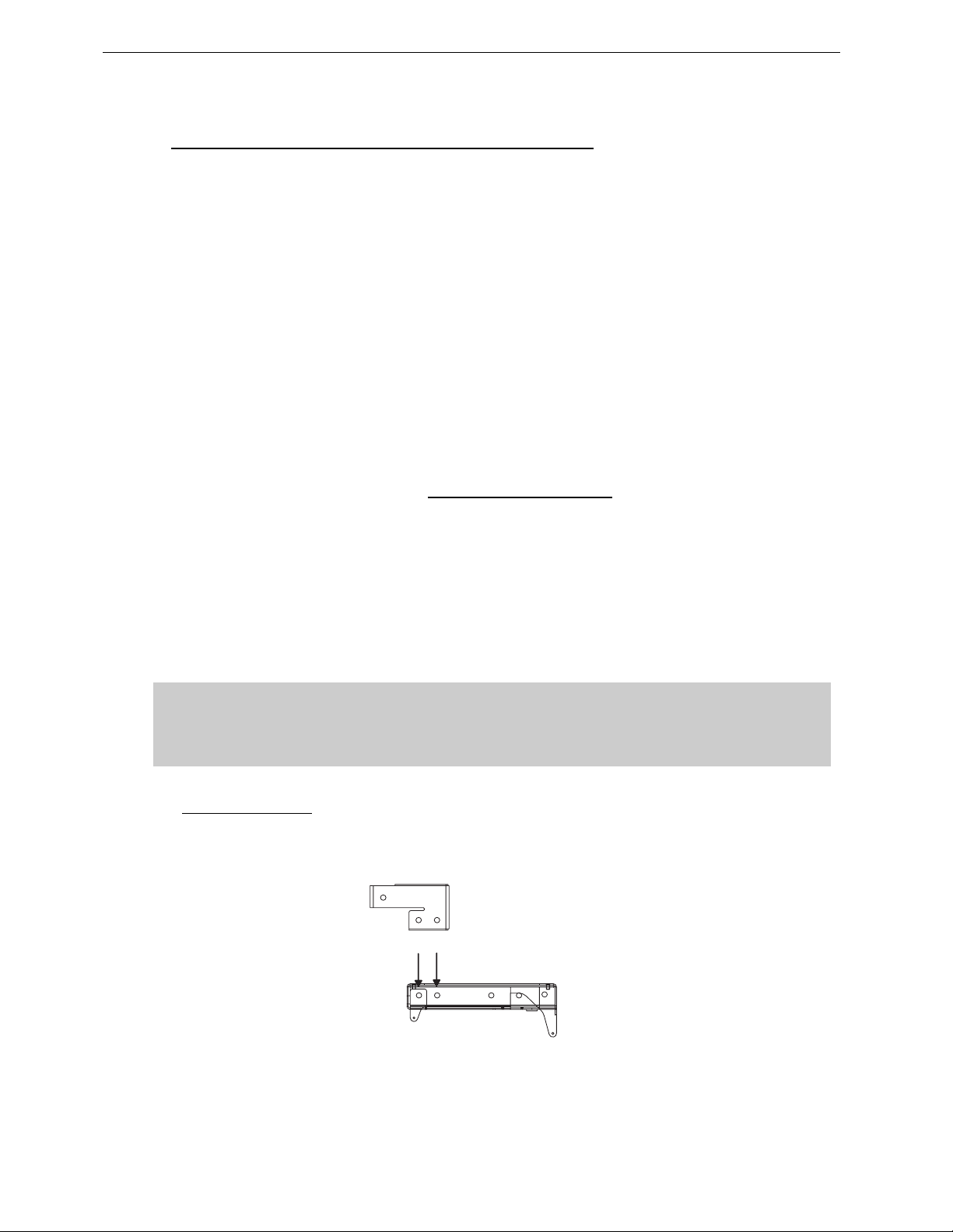
Page 58/97 GEO D RIGGING PROCEDURE
5.7 GEO SUB Cluster Flying Setup (2 motors required)
Flying a GEO SUB cluster is very similar to what has been described in the above sections,
except:
• Long Extension Bar EX2 (instead of EX1) has to be used to extend compression point
because of GEO SUB depth;
• An additional GEO D Main bumper and a Bottom Extension Bar EX3 replace t he GEO D
bottom bumper (bottom compression point being much further from the GEO SUB
rigging plates, bottom pick up point has to be a lot stronger)
However, the section below details all steps to be completed for a safe se tup.
Flying a GEO SUB cluster requires:
• 2 x Motors properly rated
• 2 x GEO D Main Bumper (GEOD-BUMPER)
• 1 x GEO D Long Extension Bar (GEOD-EXBAR2)
• 1 x GEOD Front Extension Bar if strong positive tilt is required
• 1 x GEO D Bottom Extension Bar (GEOD-EXBAR3)
• 1 x GEO D Chain Lever Hoist (LEVA0750 or LEVA1500)
• 1 x Chain Bag (CHBAG)
• 6 x GEOD push-pins per flown GEO SUB + 2 GEO push-pins for bottom GEO SUB (BLGEOD)
• or 1 x GEOD shoulder bolts and nuts kit for fixed installations per flown GEO SUB (GEOD-
BNFIX)
(GEOD-EXBAR4)
IMPORTANT
Each of front, rear motor and chain lever hoists must be rated to support the entire
cluster weight.
Please check configurations in Geosoft2 for proper motor and chain lever hoists rating
5.7.1 Bumper Assembly
• Strong bumper positive tilt only; connect the Front Extension Bar Bumper through the Link
Points the with the two axes using corresponding holes (see drawing below), and ensure that
these axes are properly locked with supplied “R” clips;
Link Points
LINKING GEOD BUMPER AND EXTENSION BAR EXBAR4
Page 59
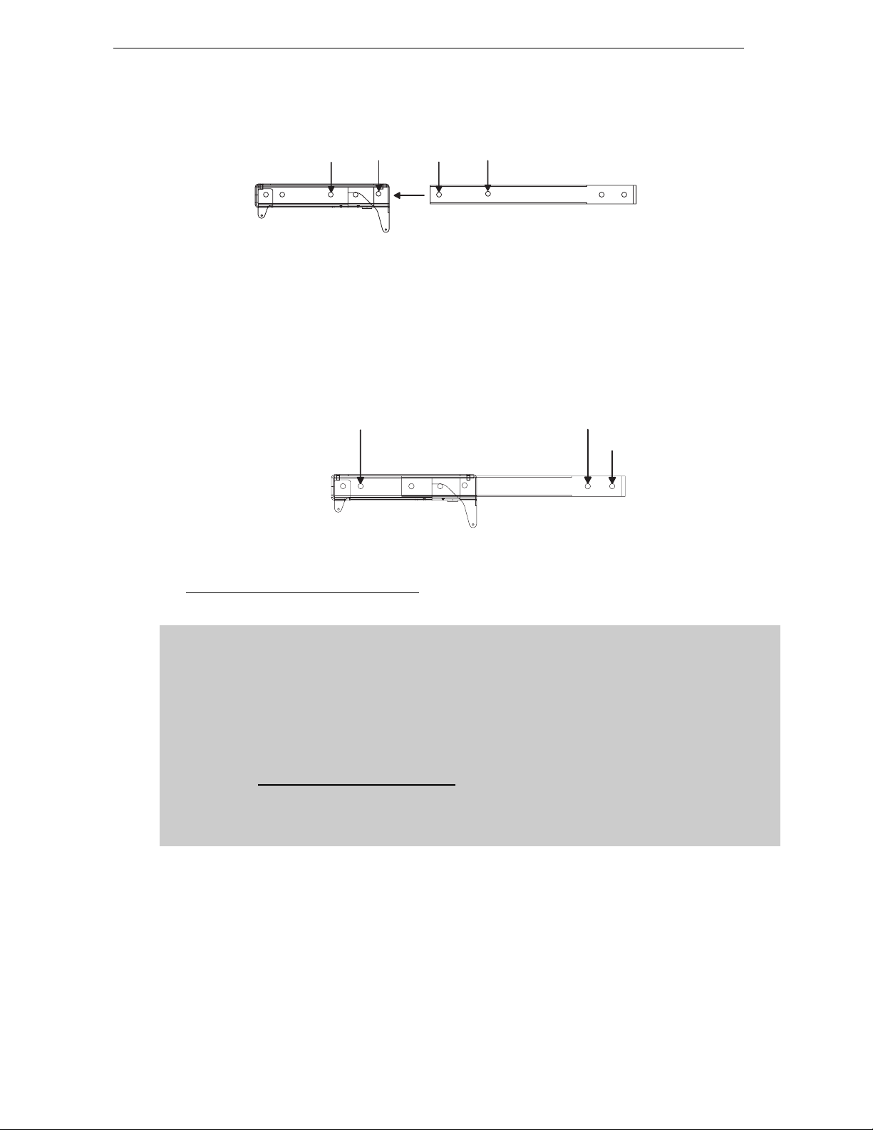
GEO D RIGGING PROCEDURE Page 59/97
• Connect the Long Extension Bar EX2 to the Main Bumper through t he Link Points the with the
two axes using corresponding holes (see drawing below), and ensure that these axes are
properly locked with supplied “R” clips;
LINK POINTS
LINKING GEOD BUMPER AND EXTENSIO N BA R EX2
LINK POINTS
• If strong positive tilt is required, front rigging point as to be extended further; connect the Front
Extension Bar Bumper through the Link Points the with the two axes using corresponding holes
(see drawing below), and ensure that these axes are properly locked with supplied “R” clips;
• Link the motor hoists to the Bumper – Extension Bar assembly to Front and Rear R igging Points
with the two axes using corresponding holes (see drawing below), and ensure that t hese axes
are properly locked with supplied “R” clips;
• Attach the chain hook of the LEVA750 or LEVA1500 Chain Lever Hoist to the Compression Point
(see drawing below).
FRONT RIGGING
POINT
REAR RIGGING
POINT
COMPRESSION
POINT
CONNECTING FRONT, REAR MOTORS AND CHAIN LEVEL HOIST
5.7.2 Bumper to first GEO SUB assembly
IMPORTANT
GEO SUB can be flown “Left” or “Right” :
- “Left” means Nexo logo on front grid is left as seen from front;
- “Right” means Nexo logo on front grid is right as seen from front.
GEO SUB can be connected to bumper “Left” or “Right” by simply flipping the cabinets
upside down: do not reverse rigging plates
Whenever possible, NEXO recommends symmetrical designs (preferably NEXO logo
inwards in stereo configurations)
Page 60
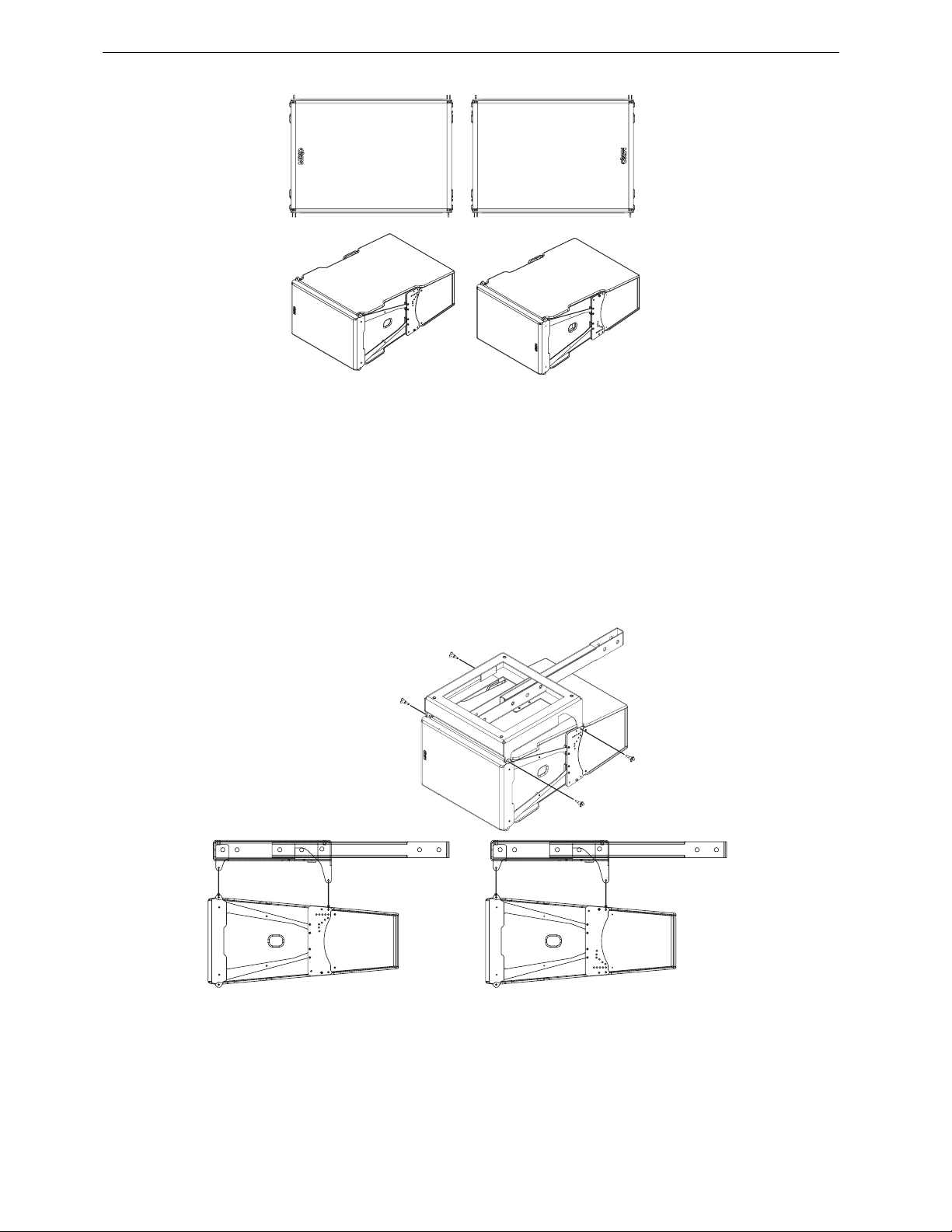
Page 60/97 GEO D RIGGING PROCEDURE
"LIFT" POINT
"LIFT" POINT
‘’LEFT’’ CONFIGURATION ’’RIGHT’’ CONFIGURATION
4 push-pins (BLGEOD, 10mm diameter x 20 mm length) connect the top GEO SUB to the bumper.
• Posit ion the bumper on the first GEO SUB by lifting or lowering bumper assembly with motor
hoists;
• Link the GEO SUB to the bumper assembly using the four 10mm x 20mm push-pins; front
bumper connects at GEO SUB front articulation point, rear bumper connects at “LIFT” GEO SUB
rigging plates holes;
• Check that all push-pins are in their locked position.
• Ensure that n o objects have been placed acci dentally on the top of the bumper as t hey may fall
when the sys te m is lif te d.
"LIFT" POINT
"LIFT" POINT
FIRST GEO SUB TO BUMPER ASSEMBLY
“LEFT“ CONFIGURATION “RIGHT“ CONFIGURATION
Page 61
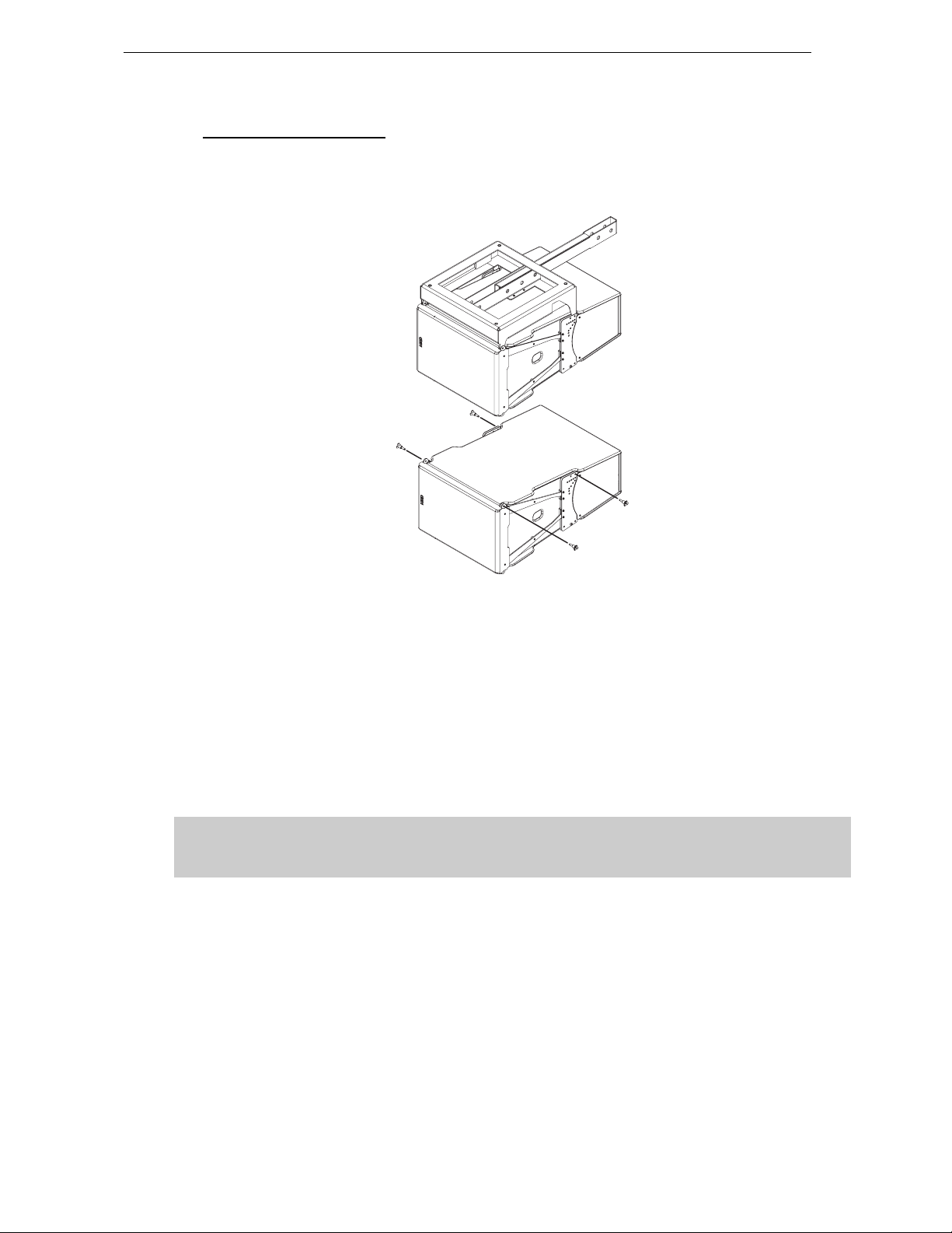
GEO D RIGGING PROCEDURE Page 61/97
5.7.3 First to second GEO SUB
4 push-pins (BLGEOD, 10mm diameter x 20 mm length) connect first to second GEO S UB, 2 additional
push pins-are required for angle adjustment.
FIRST TO SECOND GEO SUB
• Lift bumper and top GEO SUB ass embly, and position the next GEO SUB below the assembly,
with NEXO logo on the same side than the upper cabinet.
• Lower bumper and top GEO SUB assembly carefully until the first and second GEO S UB side
rigging plates locate. Use front grid, rear vent ports or handle to guide t he ass embly. The rigging
plates have been designed to locate against each other and so align the holes correctly.
• Connect the upper GEO SUB link bar to the lower GEO SUB rigging plate (or lower link bar to
upper rigging plate for “Right” configuration) by inserting one 10mm x 20 mm push-pin in the
“SAFETY PIN MUST BE FITTED” hole on each side (see figure below).
IMPORTANT
The push-pins for “SAFETY PIN MUST BE FITTED” holes must always be inserted first and
stay in position permanently. NEVER REMOVE THEM ONCE CABINETS ARE SUSPENDED.
• Insert two additional 10mm x 20mm push-pins in the front holes (see figure above).
• Lift the bumper and t wo first GEO SUB’s to a height that allows convenient access to the linking
bars and the angle setting holes.
• Insert 1 additonal push-pin to the required angle value hole on each side
• Check that all 6 push-pins are locked.
Page 62
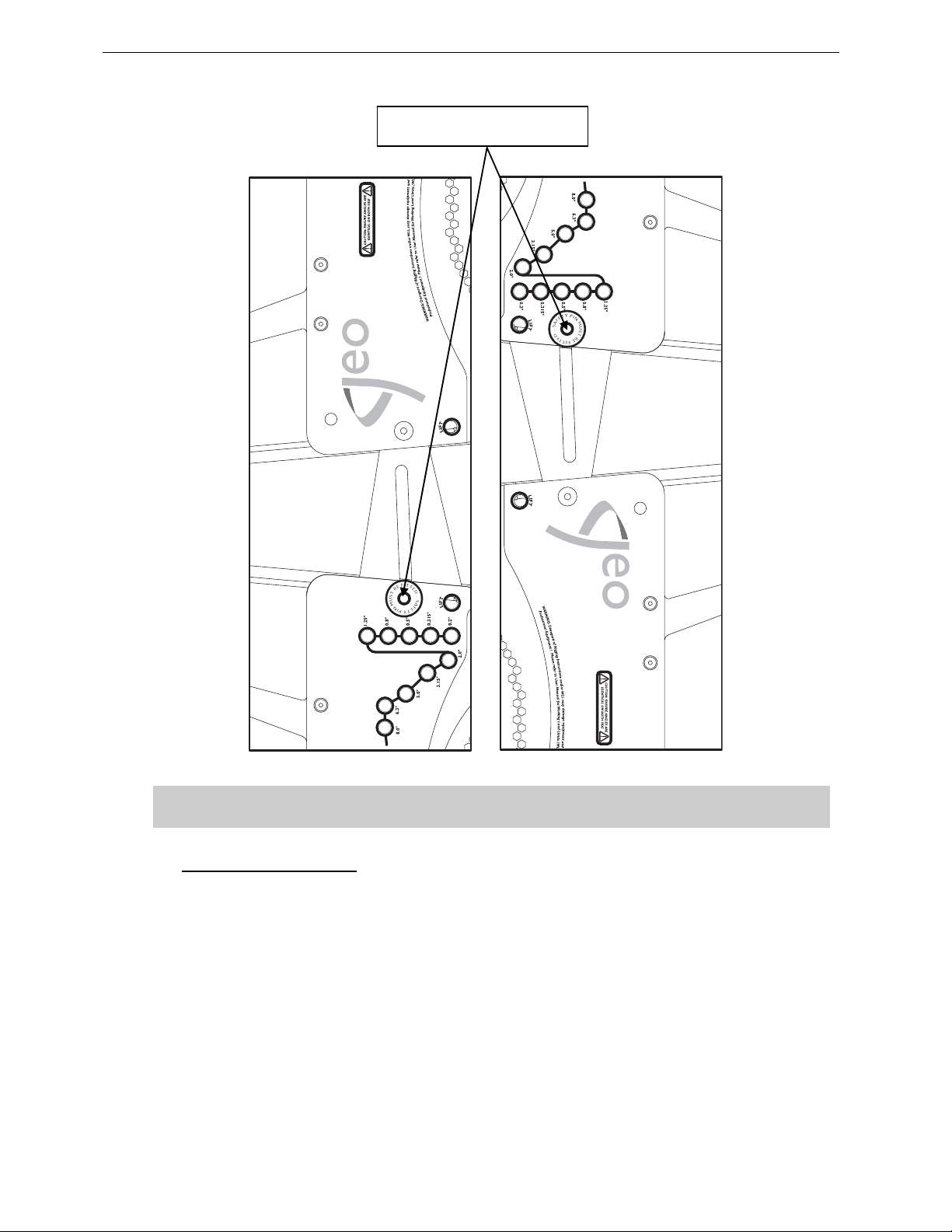
Page 62/97 GEO D RIGGING PROCEDURE
Ensure angle settings are identical on both sides of the cabinet.
5.7.4 Subsequent GEO SUB’s
« SAFETY PIN MUST BE FITTED »
HOLE
IMPORTANT
• Repeat the above section steps, until all GEO SUB’s are in place. As the assembly is lifted,
angles between GEO SUB’s cabinets will remain at 0° whatever the linking bar positions.
• N B : angle set tings are free to b e adjusted while the sys tem is clear of the gr ound, provided that
rear pull-up force is not applied.
Page 63
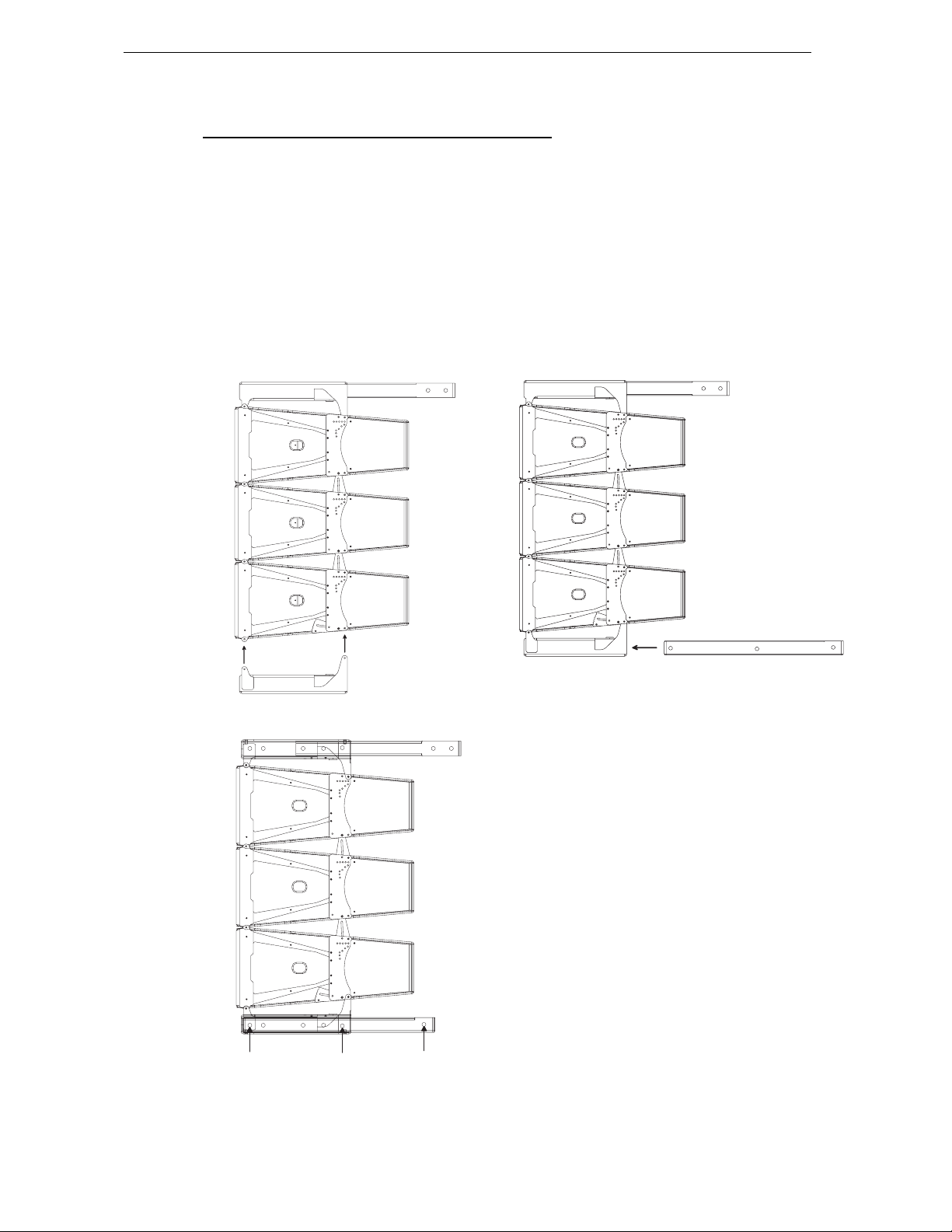
GEO D RIGGING PROCEDURE Page 63/97
5.7.5 Applying compression with the Chain Lever Hoist
• Once the GEO SUB assembly is completed, connect the second GEO D Main Bumper below
the last GEO SUB with the 10mm x 20mm push-pins inserted in the “FIX” bottom hole (see
drawings below).
• Connect the Bottom Extension Bar EX3 to the Main Bumper through the Link Points with the two
axes using corresponding holes (see drawing below), and ensure that t hese axes are properly
locked with supplied “R” clip s;
• Check the array according to the Checklist procedure described later in this manual.
• Attach the main hook of the Chain Lever Hoist to the rear of the Bottom Extension Bar EX3;
LINK POINT
LINK POINT
COMPRESSION
POINT
Page 64
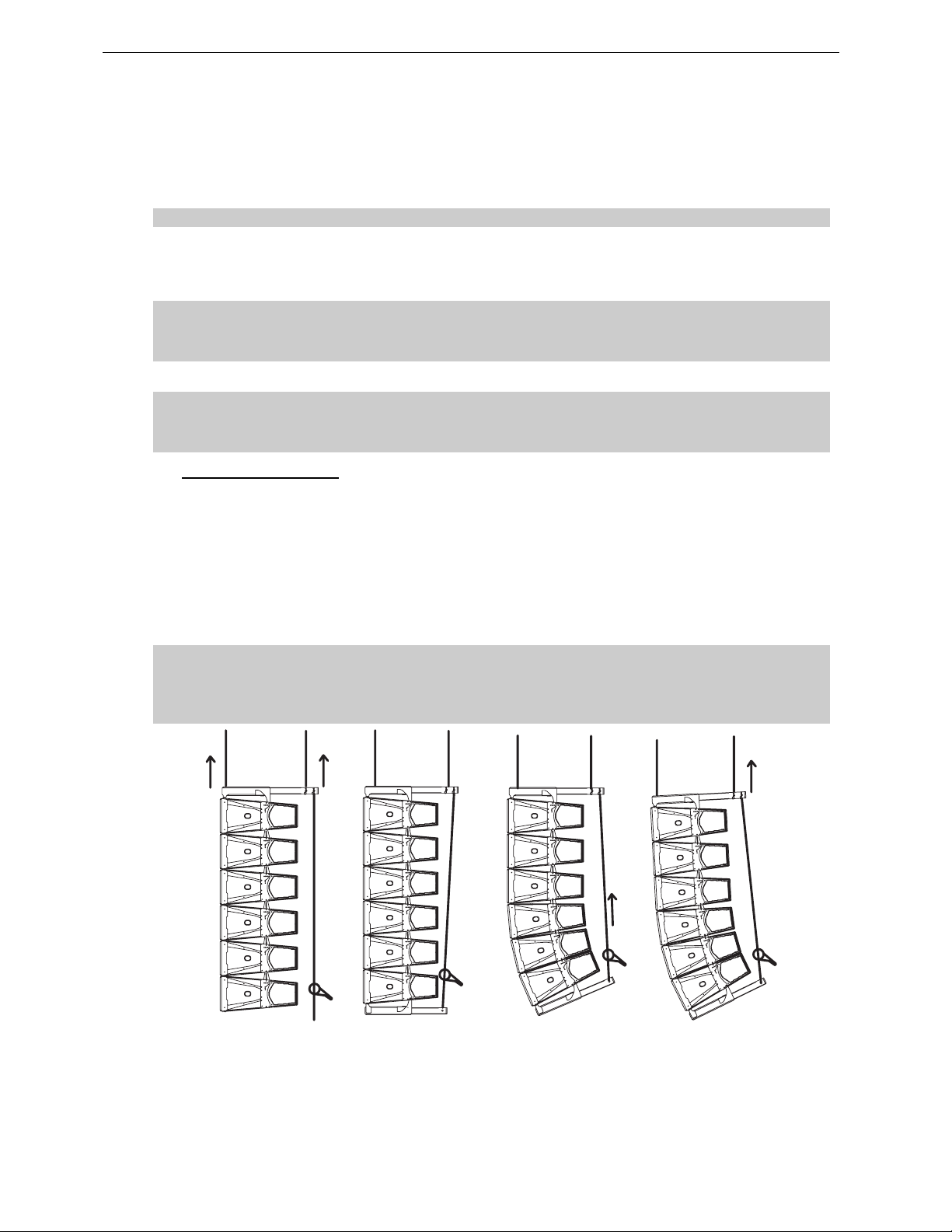
Page 64/97 GEO D RIGGING PROCEDURE
• Rotate the fingerwheel clockwise until the chain is taught;
• Make a final check that the Chain Lever Hoist is correctly installed;
• Rotate the lever to apply the pull-up force to the bottom of the array; notice that, as the chain gets
shorter, the cabinets in the array close together to the angles set by the angle adjustments pushpins;
As the chainload tensions, ensure that no twisting occurs on the chain;
• When all of the cabinets are closed together, required force to rotate the lever becomes much
stronger. This is the indication that the angles have been correctly set;
• store the surplus chain in the chain bag supplied. The chain bag should be clipped to the chain.
IMPORTANT
DO NOT attempt to force on LEVA750 or LEVA1500 lever once you feel it resisting
strongly to rotation; you might damage GEO D flying system by doing so
IMPORTANT
DO NOT attempt to make any changes to the angle adjustements when the compression
pull-up force is applied.
5.7.6 Positioning the cluster
• Lift the GEO SUB array to the height determined in GeoSoft (GeoSoft array height definition is for
the top surface of the topmost cabinet);
• Adjust the bumper angle as determined in GeoSoft by lowering or lifting rear motor hoist (so that
the front height does not change);
• Check all GEO SUB angles with an inclinometer;
• Once the bumper is in definitive posit ion a secondary safety steel must be fitted (this secondary
safety steel should link the bumper to a suitable point in the supporting structure);
IMPORTANT
The requirements for secondary safety systems vary with territories. However, the
secondary safety steel MUST have a SWL equivalent to or greater than that of the rigging
system.
APPLYING COMPRESSION AND SET TIN G BUM P ER AN GLE
Page 65
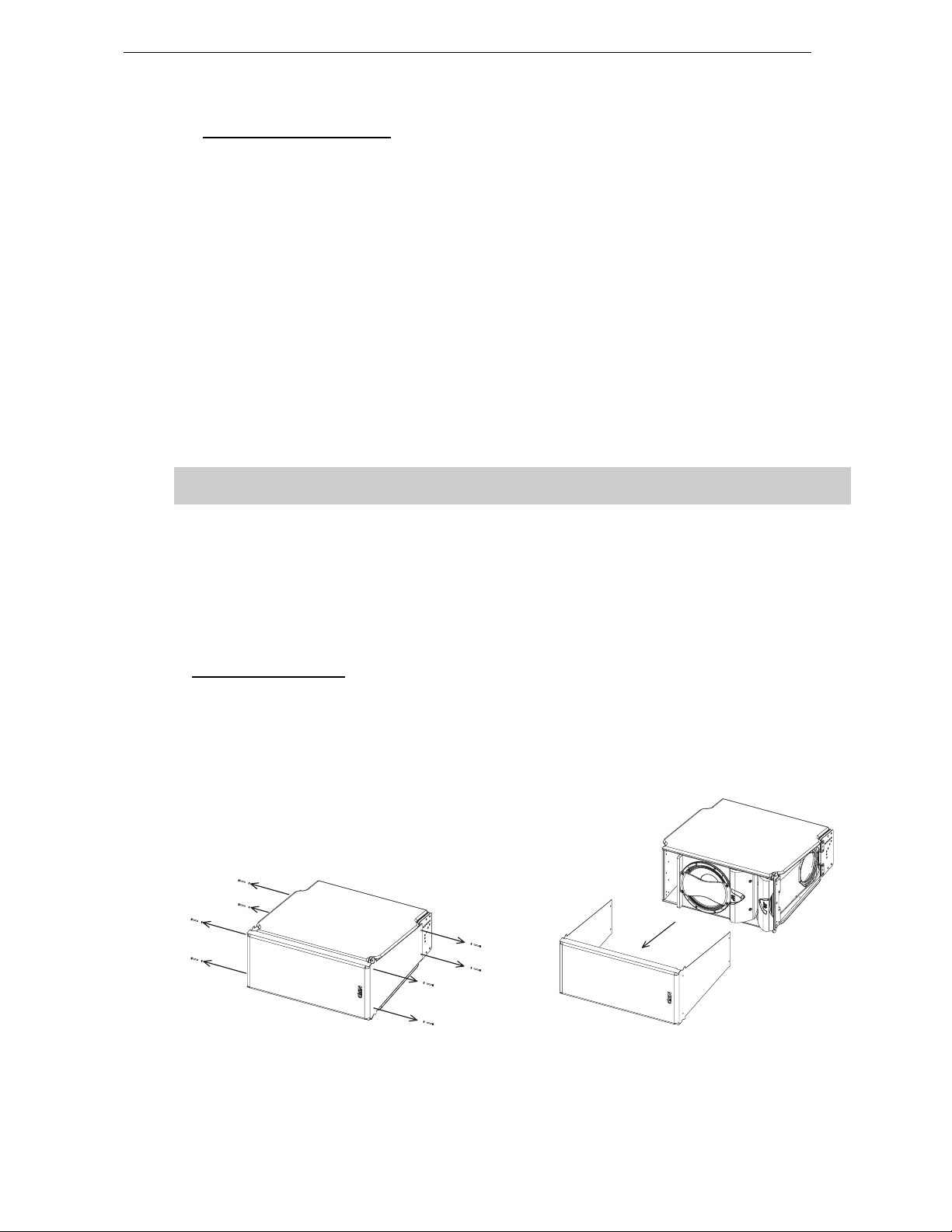
GEO D RIGGING PROCEDURE Page 65/97
5.7.7 De-rigging and loading out
Taking the system down is just a case of doing the reverse procedure to flying the array. However,
there are so me important factors to consider.
• Lower the array running the two motor hoists simultaneously until the bottom cabinet is just off
the floor, main bumper being horizontal.
• Rotate the chain hoist lever counter-clockwise until there is no tension on the GEO SUB
compression chain and no compression on the system.
• Disconnect the bottom GEO SUB from the second GEO D Bumper and remove the Bottom
Extension Bar EX3.
• NB : As the system is lowered it is good practise to disconnect as many loudspeaker cables as
can be reached without climbing the array. This ensures that a cable should not be accidentally
forgotten when the system is separated. Damage to the connector will occur should this mistake
be made.
• Angle adjustment push- pins should be removed from the angle setting and insert ed in the “FIX”
hole so that Geo SUB’s sit flat on the dolly .
• Lift the dolly manually below the array and connect it to the bottom GEO SUB with 4 push-pins.
Carefully lower the array so that the dolly being on the ground is not b eing sub mitted t o
the entire cluster weight.
• Disconnect the first block of 2 GEO SUB’s at the connection between 3rd and 4th bottom cabinets.
• Carefully lift the array using both motor hoists until the array is c lear. Ensure the array is vertical
at all times.
• Repeat the procedure for all cabinets.
• Remove the GEO D compression chain from the GEO D extension bar EX2, and remember to
replace all the axes back in their respective beams.
5.8 Fixed installations
For fixed installation where GEOD / GEO SUB clusters are permanently in position and do not need to
be removed, push-pins can be replaced with GEOD BNFIX kit.
Stacking or Rigging procedures are identical to the ones described above; however B NFIX nuts and
bolts installation will be facilitated if front grid is removed.
• remove the front grill (drawings below);
REMOVING THE GRILL
Page 66
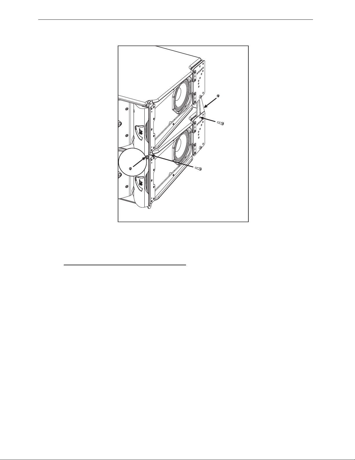
Page 66/97 GEO D RIGGING PROCEDURE
• place bolts and nuts according to drawing below
• re-install the grid, being carefull that the NEXO logo must be on the GEO W avegu ide side.
5.9 Testing and Maintenance of the system
• G eneral: Geo is a prec ision piece of e quipment and r equires regular a ttention to maintenanc e in
order to give long and reliable service. NEXO recommends regular testing of loudspeaker rigging
components, preferably using a suitable test rig coupled with a visual inspection.
• Fasteners: there are several critical points in the GEO D – GEO SUB cabinets.
Of primary concern are:
a) The grid screws attaching the grid to the cabinet
b) The machine screws attaching the rigging system to the cabinet.
c) The screws attaching the directivity flanges to the front of the cabinet.
These fasteners should be regularly checked and tightened as necessary.
• Cleaning: The exterior of the cabinet and the rigging system c an be cleaned with a damp cloth
soaked in mild soapy water. On no account use solvent based cleaners , which may damage the
finish of the cabinet
After cleaning, the rigging system must be treated with a suitable lubricant to prevent rusting. NEXO
recommends the use of Scottoil FS365 which is a water-based lubricant with a mixture of machine
oil, surfactant and anti-rust treatment.
Page 67

NEXO NX242 DIGITAL CONTROLLER FOR GEO D AND GEO SUB Page 67/97
6 NEXO NX242 DIGITAL CONTROLLER FOR GEO D AND GEO SUB
IMPORTANT
GEO SUB and GEOD10 use latest NEXO proprietary sophisticated DSP algorithm, which
require additional resources from the NX-Tension ES4 Card. All available GEO SUB and
GEO D10 setups require that NX-ES4 card is installed in NX242 TD Controller.
6.1 NX242 Proprietary Functions
The NX242 is much more than a “generic” Digital Signal Processor. It provides all the standard
functions that you expect from this type of unit, but its real value is the interface between you and your
speaker system. The NX242 includes a number of proprietary functions, developed and refined during
NEXO’s 20 years of loudspeaker development experience, to ensure that your PA delivers maximum
performance and reliability.
6.1.1 Upgradable Firmware
NEXO releases regular firmware updates. Each new release is the result of our ongoing R&D program
combined with user feedback from the field. New firmware releases can include new setups for different
combinations of NEXO full range loudspeakers and subwoofers, improvements to existing setups, and
new software functions. The NX242 is thus evolving with each of those releases, profiting from the
latest discoveries of NEXO’s R&D department as well as the experience of NEXO users.
6.1.2 EQ & Filtering
Subsonic and VHF filtering
Low and high-pass filters are used to filter out frequencies that could possibly degrade the performance
of the TDcontroller and amplifiers. The filters are optimised to work in conjunction with overall system
response.
The high pass filters are also extremely important as they help control excursion at very low
frequencies, which is a major feature for system reliability. This is one of the main reasons to avoid
using setups which are not designed for the cabinet you are using.
Equalising acoustical response
NEXO loudspeakers are acoustically designed for maximum efficiency over their operating bandwidth.
The NX242 provides the correction required to obtain a flat system response. Active rather than passive
attenuation allows the lowering of amplifier voltages for a given output SPL and therefore increases the
maximum SPL achievable with the same amplifier. Active equalisation can also extend a NEXO
loudspeaker’s frequency response, especially at low frequencies where acoustical performance is
limited by cabinet size.
While many DSP processors can provide this type of EQ, none can include the extensive measurement
facilities and listening tests employed by NEXO R&D when adjusting NX242 setups for a particular
loudspeaker.
Crossover section
Crossover between different bands is tuned for every set-up of every cabinet. The crossover is
designed to ensure the best phase alignment possible throughout the crossover overlap region.
Each crossover is “made to measure” in order that each transducer can fit with its neighbour by
achieving a perfect phase alignment. Unconventional filters are used, ranging from 6dB/octave to near
infinite slopes depending of the type of crossover wanted. Time alignment is also performed in an
unconventional way, by using the crossover filter group delays in combination with allpass and/or
frequency dependent delays.
Page 68
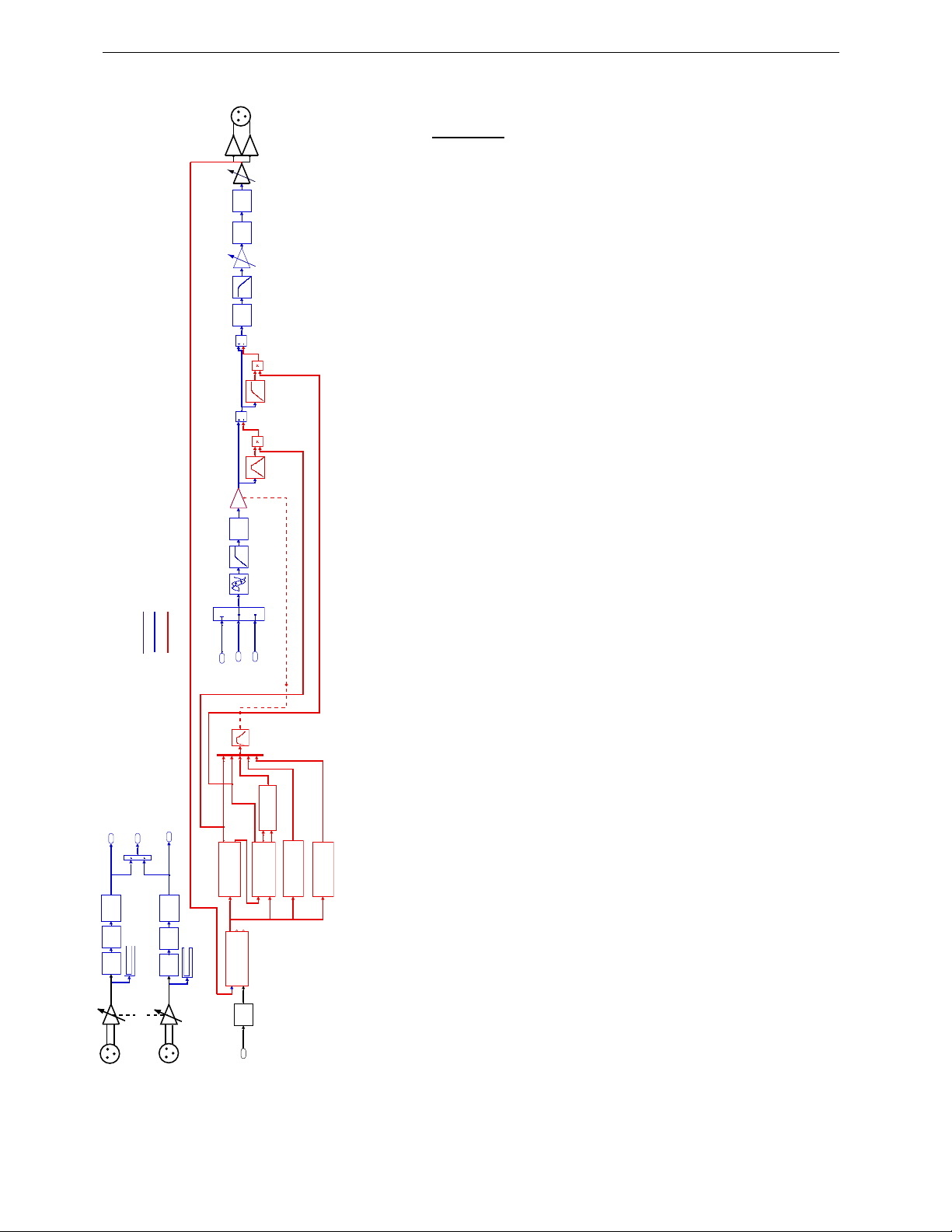
Page 68/97 NEXO NX242 DIGITAL CONTROLLER FOR GEO D AND GEO SUB
0
OUTPUT
CHANNEL 4
VCAs and VCEQs
Each channel has its own simulation and protection process.
DACMUTEEQ
Each audio channel contains a combination of controlled gain stages
(let's call them VCAs as in analogue circuitry). These VCAs are
embedded into complex composite signal chains that adapt change their
basic operation into frequency selective attenuation, similar to an analog
voltage controlled dynamic equaliser (VCEQ).
Each VCEQ and VCA is controlled via synthesis of several signals from
the various detection sections. That synthesis is in fact the envelope of
those signals, with an optimised release and attack time for each VCEQ
and VCA (depending on its frequency range and the cabinet selected).
Displacement Control
6.1.3 Protection
The Sense input signal is sent to a shaping filter producing a signal
whose instantaneous amplitude is proportional to the voice coil
excursion. This signal, after rectification, is compared to a preset
threshold matching the maximum usable value, as determined from
VCA
EQ
laboratory measurements. Any part of the signal exceeding the threshold
is sent to the VCEQ control buffer while the VCEQ acts as an
instantaneous (very short attack time) limiter to prevent displacement
from exceeding the maximum permissible value.
Temperature Control
1
R
Command
displacement
DISPLACEMENT 1
Signal
AMP POWER
FALLBACK
DELAY 1
2L 3
R+L
ATT/REL.
Command
Disp.
AMP GAIN
AMP VOLTAGE
A/D
5
SENSE 1
PATCH
Command
PHYSIO 1
Voice Coil Temp.
ChassisTemp
ChassisTemp.
Voice Coil Temp.
LF TEMPERATURE
Command
Analogue path
Digital Audio
Digital servo & protections
NX242 Digital TDcontroller Partial BLOCK DIAGRAM
2
L
3
1
R
R+L
SHELVING
A/D EQ
INPUT VU-METER
HEADROOM
INPUT R
SHELVING
A/D EQ
INPUT VU-METER
INPUT L
Each sense signal is fed into a shaping filter (one per transducer), each
one producing a signal proportional to the instantaneous current flowing
into the voice coil of the transducer. After rectification, this signal is
integrated with attack and release time constants equivalent to the
thermal time constants of the voice coil and chassis, producing a voltage,
which is representative of the instantaneous temperature of the voice
coil.
When this voltage reaches the threshold value corresponding to the
driver’s maximum safe operating temperature, the VCA becomes active
to reduce the NX242’s output signal level until the effective temperature
falls below the maximum usable value.
In order to avoid detrimental effects induced by very long release time
constants produced by the temperature detection signal (system output
being reduced for an extended period, “pumping” effects, etc.), the
detection signal is modulated by another voltage integrated with faster
time constants that match the subjective perception of sound level. This
allows the controller to reduce the effective operating duration of the
HF TEMPERATURE
PEAK SIMULATION
Command
temperatu re limiter an d make it sound more natural , while the ef ficiency
of protection is fully preserved and protection thresholds are kept as high
as possible.
Physiologic Dynamic Control
The Physiologic Dynamic Control is intended to avoid unwanted effects
produced by long attack time constants. By anticipating the operation of
the temperature limiter, it prevents a high level audio signal appearing
suddenly, then being kept up for long enough to trigger the temperature
limiter. Without this, a rough and delayed gain variation would result that
would be quite noticeable and unnatural.
Page 69

NEXO NX242 DIGITAL CONTROLLER FOR GEO D AND GEO SUB Page 69/97
The Physio control voltage acts independently on the VCA with its operation threshold slightly (3 dB)
above that of the temperature limiter and a low compression ratio; its optimised attack time constant
allows it to start operating without any subjectively unpleasant transient effects.
Peak Limiter
The peak limiter primary function is to avoid massive clipping of the amplifier, which can have some
very audible artefacts and in some cases may be damaging to the loudspeakers. Modulation of the
amplifier’s supply voltage rails can create very low frequencies or high-frequency, high level harmonics.
Since thes e occur after the NX242 in the signal path, they are not filtered by the TDcontroller circuitry.
The threshold of the peak limiter is set by the user to match the amplifier’s clipping point.
The second function of the peak limiter is to avoid huge amounts of power being sent to a driver. Each
driver is protected against overheating and overexcursion, but there could be ot her failure modes that
cannot be predicted by simulation (especially mechanical damage to the cone). Each driver is specified
for a certain power handling and a factory set peak limiter threshold is tuned to avoid any abuse.
6.2 Cardioid LF and VLF
Cardioid LF and V LF is one o f th e key advan ces of th e GE O D / GE O SUB sys tem. T his featur e is only
achievable with a total control of the DSP chain. Although the basic concept as presented in audio text
books is relatively simple, producing a cardioid pattern from a loudspeaker without a major loss of
efficiency requires advanced DSP processing.
Other “loudspeaker management” DSP devices do not provide the algorithms that the NX242 uses to
optimise the cardioid operation of the GEO D10 and GEO SUB.
GEO D10 LF and GEO SUB dispersion are digitally set to a cardioid pattern by adjusting the front and
rear loudspeakers phase and amplitude relationship. Average rear to front attenuation is more than 12
dB.
6.3 GEO D NX242 Setups description
6.3.1 GEO D10 Passive Mode (Stereo Setups)
Hardware configuration
• Input can be selected in the MENU 3.2 (L, R or L+R);
• Output 1 drives left GEO D side-firing LF 8 inch neodymium transducers;
• Output 2 drives left GEO D front-firing LF/MF 12 inch neodymium transducers and the HF 3-inch
voice coil, 1.4 inch ex it co mpression d river ;
• Output 3 drives right GEO D side-firing LF 8 inch neodymium transducers;
• Output 4 drives right GEO D front-firing LF/M F 12 inch neodymium transducers and the HF 3-
inch voice coil, 1.4 inch exit compression driver.
6.3.2 GEO D10 Active Mode (Mono Setups)
Hardware configuration
• Input can be selected in the MENU 3.2 (L, R or L+R)
• Output 1 drives GEO D side-firing LF 8 inch neodymium transducers;
• Output 2 drives GEO D front-firing LF/MF 12 inch neodymium transducer;
• Output 3 drives GEO D HF 3-inch voice coil, 1.4 inch exit compression driver;
• Output 4 is not used.
Page 70

Page 70/97 NEXO NX242 DIGITAL CONTROLLER FOR GEO D AND GEO SUB
6.3.3 GEO SUB (Stereo Setups)
Hardware configuration
• Input (L, R or L+R) can be selected in MENU 3.2
• Output 1 drives left GEO SUB side-firing 12 inch transducers;
• Output 2 drives left GEO SUB 18 inch transducer;
• Output 3 drives right GEO SUB side-firing 12 inch transducers;
• Output 4 drives right GEO SUB front 18 inch transducer.
6.3.4 GEO SUB & GEO D Passive (Mono Setups)
Hardware configuration
• Input (L, R or L+R) can be selected in MENU 3.2
• Output 1 drives GEO SUB side-firing 12 inch transducers;
• Output 2 drives GEO SUB front 18 inch transducer;
• Output 3 drives GEO D side-firing LF 8 inch neodymium transducers;
• Output 4 drives GEO D front-f iring LF/MF 12 inch neodymium transducers and the HF 3-inch
voice coil, 1.4 inch exit compression driver.
6.3.5 GEO SUB & GEO D Setups
Typical setup families are:
• GEOD WIDEBAND: GEOD starts at 55 Hz. This setup family is recommended for applications
which are not VLF demanding;
• GEO SUB & GEO D X-OVER: GEO SUB is low-passed at 75 Hz and GEO D is high-passed at
75 Hz. This setup family is recommended when GEO SUB’s are stacked and GEO D flown, and
distance between them exceeds 2 meters (6 feet).
• GEO SUB & GEO D OVERLAP: GEO SUB is low-passed at 300 Hz and GEOD is high-passed
at 75 Hz. Therefore, they “overlap” from 75 Hz to 300 Hz. This setup family requires proper
phase alignment between systems up to 300 Hz, and is therefore is recommended when GEO
SUB’s and GEO D are flown together, or when distance between them is lower than 2 meters (6
feet).
Please be aware that setups are periodically revised, refer to the latest versions of the NX242 user
manual and firmware (www.nexo-sa.com).
6.4 Trouble shooting
The NX242 has been designed to be user-friendly. However with highly technical systems such as GEO
D & GEO SUB, incorrect adjustment of the NX242 can lower the quality & safety of your system. Listed
below are the most common errors encountered by NEXO Technical Support.
6.4.1 Operation of Multiple TDcontrollers
Typically, GEO D / GEO SUB systems require multiple NX242’s per side. Eventually, two or more
NX242’s will operate within the same cluster. It is mandatory to verify the consistency of the setups and
adjustment between proces s o rs t o av o i d the problems described below.
IMPORTANT
When using multiple NX242’s in a single array, all parameters should be identical and set
to proper values.
Page 71

NEXO NX242 DIGITAL CONTROLLER FOR GEO D AND GEO SUB Page 71/97
6.4.2 Amplifier Power (MENU 2.7)
If the amplifier power (MENU 2.7) is set to a value below the amplifer’s actual power, the peak limiter of
the NX242 will trigger continually, creating audible distortion. Please note that this peak limiter is not set
to act as a compressor on the signal. It is intended to minimize the clipping of the amplifier by operating
slightly after
One way to properly adjust this parameter is to set amplifier power at maximum (5000W) and decrease
the value until the amplifier and TDcontroller clip at the same time.
the amplifier’s clipping point.
6.4.3 Amplifier Gain (MENU 2.6)
It is very important to check the gain of each c hannel. These values should be set in agreement with
amplifier gain. The second line of the MENU2.6 displays the gain as seen by the NX242 to ease the
setting of this parameter.
6.4.4 Gains
If your amplifier gains are not the same on each channel, you will have to adjust the inter-channel gain
in order to compensate for this amplifier gain difference.
6.4.5 Delays
Multiple NX242’s can be used on a single GEO D array. When changing the delay in one NX242
TDcontroller that is part of a multi-controller system, take great care to have exactly the same delay
setting in all NX242 TDcontrollers that receive the same input signal (i.e. all NX242’s that are fed from
the Left output of the mixing console should have the same delay settings). A Tangent Array is very
sensitive to delay differences between sections of the array in the same line. You could experience
coverage problems if all delays applied to a Tangent Array are not equal.
Please refer to the chapter in the NX242 User Manual on setting delay for proper time alignment
between GEO D’s and GEO SUB’s.
6.4.6 Reversed Cardioid Pattern
Polarity checks are often performed while the system is being set up. Keep in mind that cardioid
speakers may also require a coverage test. If you invert two outputs of the NX242, you could have the
main lobe inverted and firing to the rear. It may be quite hard to detect a reversed cardioid patt ern when
it involves one section of a large array.
A good practice is to test the each cabinet in the array with the front speakers only. The system is then
omni-directional. Then turn on the back speaker: you should notice a massive reduction at the back,
and additional level at the front.
This test must be done in addition to the usual polarity test.
6.4.7 Using the wrong NX242 setups for a given cabinet
Each NX242 setup is tailored for a certain NEXO loudspeaker. Using the wrong setup will create safety
and quality problems. Always check that every cabinet in your system is being driven by the c orrect
NX242 setup.
6.4.8 Connections
To ensure correct electronic behaviour, and to guarantee specifications and EMC performance, a
NX242 must be properly wired. Always use balanced connectors with the shield connected to pin 1 on
both sides. For mo re wirin g rec omm endat ions ple ase refe r to t he appli cat ion n ote i n th e NX 242 m anu al
update.
Page 72
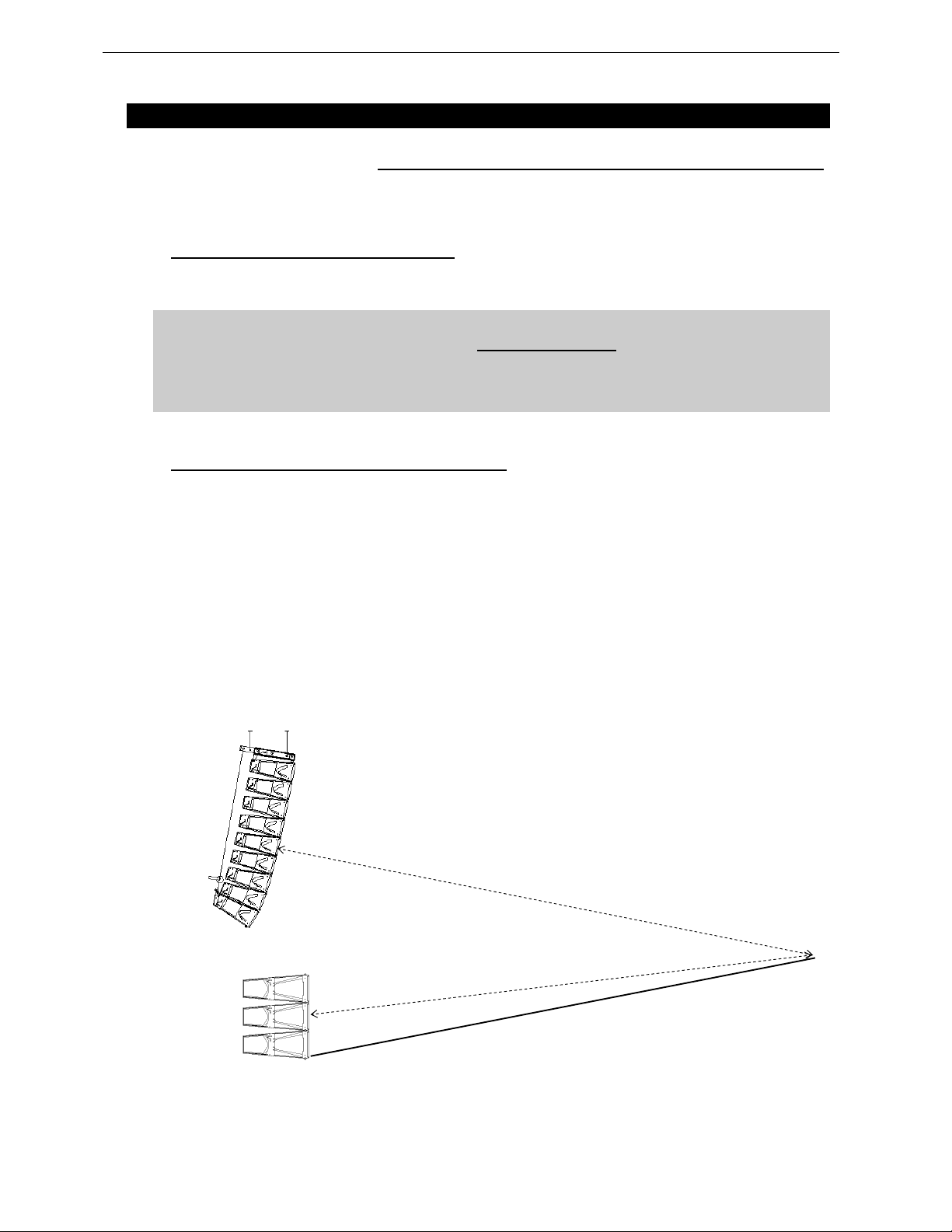
Page 72/97 SYSTEM ALIGNMENT GUIDELINES
r
7 SYSTEM ALIGNMENT GUIDELINES
The NX242’s factory delay presets are optimised to provide the best possible crossover between the
GEO D and GEO S UB systems. The refere nce point for this adjustment is the fron t of each cabinet
.
(This means that the internal delays needed to achieve a correct time alignment are set for cabinets
standing next to each other with both fronts aligned). We recommend that the system is adjusted so that
arrivals from GEO D and GEO SUB are coincident at a fairly distant listening position.
7.1 GEO SUB – GEO D Cluster design
Cluster desi gn mus t be done with G eosoft 2, whic h prov ides ve ry int uitive and fas t metho d to det ermin e
all cluster geometry parameters in relation to venue where cluster is implemented.
IMPORTANT
Geosoft2 is a freeware downloadable on www.nexo-sa.com. Please check our website
periodically for upgrades.
Never install a GEO D / GEO SUB cluster without checking its acoustical performances
and mechanical safety in Geosoft2 prior to installation.
Please contact your local distributor for assistance and/or training on Geosoft2
7.2 Stacked GEO SUB’s and Flown GEO D’s
Recommended NX242 GEOD setup family: X-OVER
In the example below, r
distance from GEO SUB to listener position, the distance difference is then r
feet).
being the di stance from GEO D arra y to listener posit ion, and r2 being the
1
(specified meters or
1–r2
> r2, the delay should be set on the GEO SUB NX242 TDcontroller.
• r
1
< r2, the delay should be set on the GEO D NX242 TDcontroller
• r
1
• To convert the result in time delay (specified in seconds), apply:
∆t = (r
)/C r1 and r2 in meters, C (sound speed) ≈ 343 m/S.
1-r2
The delay parameter is set in MENU 1.2 (set the units to meters, feet or seconds according to your
preference). Delay will have to be adjusted according to the distance difference r
(see figure below).
1–r2
Page 73

SYSTEM ALIGNMENT GUIDELINES Page 73/97
7.3 Flown or Stacked combined GEO SUB’s and GEO D’s clusters
Recommended NX242 setup family: OVERLAP
When GEO SUB’s are flown or stacked within the GEO D array, GEO SUB delay should be set at the
same value than GEO D’s, ie there should be no delay difference between systems.
7.4 Separate GEO SUB and GEO D clusters
Delay must be set to compensate for horizontal distance offset between front edges.
When GEO SUB’s and GEO D’s are flown in separate clusters, distance between clusters should be:
NX242 GEOD setup family: OVERLAP
• 1.25m (4 ft) minimum center to center or 50cm (1.5 ft) side to side;
• 1.75m (6 ft) maximum center to center or 1m (3 ft) side to side.
NX242 GEOD setup family: X-OVER
• 1.25m (4 ft) minimum center to center or 50cm side to side;
• No upper limit.
7.5 Driving the GEO SUB’s from the AUX send
It is quite common to use the AUX send of a mixing desk to drive the Sub section of a PA system. This
gives the mixing engineer more flexibility to set the level of the subbass relative to the main PA, apply
special effects, or to use a different EQ on the Sub. However, it also raises some serious issues for the
performance & safety of the system (mostly time alignment).
At NEXO, great care is taken to design optimum phase alignment from one octave above to one octave
below the crossover frequency point. By doing so, drivers are working perfectly together and providing
the best efficiency possible. It is then up to the user to adjust the delay on the NX242 to match the
physical path difference of the different systems. It is thus possible to get a well adjusted system, even
without measuring instruments.
If GEO SUB’s are driven form an AUX output, NX242 is fed with two signals coming from different
sources. If those two sources (MAIN output & AUX send) are not exactly in phase, delay is introduced
into the crossover between the GEO D array and the GEO SUB’s . It is then mandatory to use proper
measurement tool to optimize phase response.
Why is it unlikely that AUX and MAIN outputs have the same phase?
• Signal paths are likely to be different; any filter modifying the bandwidth and EQ of the
signal is also affecting the phase.
Example: a 24dB/oct high pass filter set at 15Hz is affecting amplitude of the signal by only
0.6dB at 30Hz, but the phase shift is 90°!! At 100Hz we can still measure 25° of phase shift.
• Limiting bandwidth with a low pass filter can introduce a phase difference of up to 180°
(completely out of phase) at the cross over point.
• If the signal is passing though any digit al equipment, between 1.4ms and 2.2ms is being
added (around 70° phase shift at 100Hz) due solely to the converter delay! The additional
delay due to t he proce ssing i tself ( look ahea d compr essor, de lay…) c an be quit e import ant
as well.
If both outputs are not measured in the actual configuration, it is very likely that phase alignment will not
be correct.
Page 74

Page 74/97 SYSTEM ALIGNMENT GUIDELINES
Consequences of badly aligned systems
Mis-aligned systems have lower efficiency: i. e. for the same SPL the system will have to be driven
harder, activating the displacement & temperature protection at lower output levels. Both sound quality
and reliability will decrease as the system is stressed.
Precautions & Checks
Before using the AUX of a mixing desk, ensure that MAIN and AUX outputs are in phase;
Always apply identical EQ or processing on both channels, so that the phase relationship will not be
altered;
Never add additional low pass filtering on the SUB or high pass filtering on the main system;
Inverting polarity on one channel should always result in a massive difference near the crossover point.
If that is not the case, the system is no longer aligned.
7.6 Recommended installation tools and equipment
• Tape measure – should be 30m/100ft in length and be of durable fibre material. Have one per
array available to speed up the installation process.
• Las er Inc linometer – For measuring vertic al and horizontal angles in the venue. An ideal product
is the Calpac ‘Laser projecting a dot’ version which cost s approximately 60 €.
• Digital remote inclinometer – with a remote sensor in the bumper and a meter unit at ground level
to ensure precise installation of the cluster. NEXO GeoSight system predicts the stationary angle
of the array, even while it is swinging, and has a green laser mounted coincident to and parallel
with the axis of the topmost cabinet.
• Spirit level – used to ascertain the trueness of the surface from which the angle measurements
originate.
• Rangefinder measuring device – either a Disto type laser measure or an optical laser rangefinder
can be used. Devices such as the Bushnell ‘Yardage Pro’ sports rangefinders provide sufficiently
accuracy and are easy to use. They have the additional advantage of working very well in bright
sunlight.
• Electronic calculator with trigonometric functions to calculate the height from ground level to
points in the room. The formula to calculate height of a point from measured angle and distance
is:
• Height of point = Sin(vertical angle in degrees) x distance to point
• NB: Take care when using spreadsheets as they calculate using radians by default. To convert
degrees to radians use the formula:
• Angle (in radians)=3.142 x Angle (in degrees)/180
• Computer – Laptop or Desktop PC running Win dows 2000 or XP wit h the c urrent version of
NEXO GeoSoft2 installed. It is not possible to configure a Geo tangent array properly without
using GeoSoft2. Note that, when GeoSoft2 designs are prepared prior to arrival at the venue, it is
often necessary to modify or update the design to accommodate special circumstances. A PC is
absolutely essential to make such changes.
• Audio Analysis Software – recommended but not absolutely essential, programs such as SIA
Smaart Pro, Spectralab or Spectrafoo enable rapid and detailed analysis of the installation.
Consider taking a training course in using one of these tools if you are not already competent
with them – it will pay dividends in increased performance of the system.
Page 75
GEO D – GEO SUB ARRAY SYSTEM CHECK LIST Page 75/97
8 GEO D – GEO SUB ARRAY SYSTEM CHECK LIST
It is essential to execute all these check steps prior to perform a sound check on the “front end” to the
system. Following this checklist step by step will prevent many troubles and will save time in the end.
8.1 Are the NX242 Digital TDcontrollers properly configured?
IMPORTANT
If you must change any of the parameters listed above, make sure that you use the same
values on all NX242’s.
8.1.1 NX242 settings
Output Assignment
NX Setup / NXChannel 1 2 3 4
GEO SUB – GEO D Passive Mono GEO SUB Rear GEO SUB Front GEO D Rear GEO D Front
GEO SUB - Stereo GEO SUB Rear GEO SUB Front GEO SUB Rear GEO SUB Front
GEO D Passive Stereo GEO D Rear GEO D Front GEO D Rear GEO D Front
GEO D Active GEO D Rear LF GEO D Front LF/MF GEO D Front HF -
Output parameters
Output
Label
All channels (GEO D and GEO SUB) 26 dB
(1) values for recommended amplifier gain and power : should be set in agreement with selected
amplifiers specifications
(2) Local gain and delay values are inter-locked channel 1&2 and 3&4
(3) Should be in agreement with implemented cluster; acts on a shelving filter designed to compensate
for LF coupling (6 GEOD is 0dB gain on shelving filter, less than 6 is positive gain, more than 6 is
negative gain)
(4) Disabled when using digital inputs.
Amp
Gain (1)
Amp
Power (1)
1600 W/8Ω
Global
Gain (2)
0 dB 0 ms 0 dB 5 bars
Global
Delay (2)
Sense
Gain
Speaker
Qty (3)
Headrom
(4)
8.2 Are the amplifiers properly configured?
Freq. Band Mode Gain Switch Limiter High Pass
All channels (GEO D and GEO SUB)
Stereo 26 dB None None
8.3 Are the amps and the NX properly connected?
Check that the sense lines on the NX242’s are properly connected by applying a signal to the
corresponding output and verify that the correct Sense LED illuminates.
8.4 Are the speakers properly connected and angled ?
• Attach the first serie of modules to the bumper.
• Before flying, verify that all channels of all modules are functioning properly.
• Make sure that each GEO D10 / GEO SUB is producing the proper front/rear summation: when
listening from behind the array, switch the front drivers in and out. You should hear a reduction in
the LF range when the both front and rear drivers are on as compared to when the rear drivers
Page 76

Page 76/97 GEO D – GEO SUB ARRAY SYSTEM CHECK LIST
only are on. When listening from the front, you should hear a strong increase in the LF range
when connecting the rear drivers.
• To check that all front elements have the proper amplitude and phase, you should li sten to the
upper boxes at a close distance (<1 meter). You should be able to move from the top to the
bottom of the cluster without hearing any change in the tonal balance.
• Verify that the angle settings are the same on both sides of each module.
• Raise the bumper, attach the next serie of modules and repeat the above checks.
• Make sure that these serie of modules sum properly with the modules above them.
• When all the modules are flown, check that the aiming angles are the same left and right.
• Make sure that multiple GEO D’s and GEO SUB’s are summing properly: 6 dB gain per doubling
of quantity.
8.5 Final Pre-Sound Check Check
Play a CD track mono left, and then right : both sides must sound strictly identical. When listening in the
center betwe en two GEO D / GEO SUB ’s, every thing from LF to HF sh ould be loc ated to th e “phantom
center” position. If not, repeat the above check sequence to identify the source of the problem.
Page 77
TECHNICAL SPECIFICATIONS Page 77/97
9 TECHNICAL SPECIFICATIONS
9.1 GEO D10 Vertical Tangent Array Module
9.1.1 System specifications
PRODUCT FEATURES GEO D10
Components HF: 1 x 3” voice coil, 1.4” throat 16 Ohms driver on a 5° hyperboloid reflective wavesource.
Height x Width x Depth 380 x 744 x 750 mm (15” x 29
Shape 10° Trapezoid.
Weight: net 57 kg (125.7 lbs) including array assembly system.
Connectors 1 x AMPHENOL EP6 6 pole socket In; 1 x AMPHENOL AP6 6 pole connector Through.
Construction Baltic birch ply with structured black coating.
Front finish Molded Dark Grey Metal Grill.
Flying points Integral flying system.
SYSTEM SPECIFICATIONS GEO D10 with NX242 Tdcontroller & NX-tensio n Ca rd
Frequency response [a] 60 Hz – 19 kHz ± 3 dB
Usable range @-6dB [a] 55 Hz – 20 kHz
Sensitivity 1W @ 1m [b] 105 dB SPL nominal (103 dB SPL wideband)
Peak SPL @ 1m [b] Configuration dependent [d].
Dispersion [c] Vertical plane: Configuration dependent [d].
Crossover frequencies LF-MF: 300 Hz active; MF-HF: 1.1 kHz Passive or Active (internally configurable)
Nominal impedance HF: 16 Ohm; LF/MF front: 16 Ohm; LF rear: 16 Ohm
Recommended amplifiers
3 GEO D10 in Parallel
4 GEO D10 in parallel
6 GEO D10 in parallel
SYSTEM OPERATION
Electronic controller The NX242 Digital TDcontroller (with NX-Tension Card) presets are precisely matched to the GEO D Series cabinets
Array design Arrays of less than 3 x GEO D10 will provide poor dispersion control and are neither recommended nor supported.
Sub-bass GEO SUB directional sub extends system low frequency response down to 35 Hz
Speaker cables Active: 5(-) / 6(+): HF; 3(-) / 4(+):LF/MF Front ; 1(-) / 2(+): LF Rear.
Rigging System Please refer to the GEO user manual before any operation.
As part of a policy of continual improvement, NEXO reserves the right to change specifications without notice.
[a] Response curves and data: anechoic far field above 200 Hz, half-space anechoic below 200 Hz.
[b] Sensitivity & peak SPL: will depend on spectral distribution. Measured w ith band limited pink noise.
Refers to the specified +/- 3 dB range. Data are for speaker + processor + recommended amplifier combinations.
[c] Directivit y curves and data: 1/3 octave smoothed frequency response, normalized to on-axis response. Data obtained by computer processing of off-axis
[d] Please refer to the GEO D user Manual.
Usable range data: frequency response capability with TD crossover slopes removed.
response curves.
MF/LF (front-firing): 1 x 12” (30cm) high excursion neodymium 16 Ohm driver.
LF (side-firing): 2 x 8” (20cm) neodymium 8 Ohm drivers in series.
Rigging axis to axis h eigh t: 344m m (13
Intercabinet angle adjustments = 0.2°, 0.315°, 0.5°, 0.8°; 1.25°, 2.0°, 3.15°, 5°, 6.3°, 8.0°, 10.0° (logarithmic steps)
Horizontal plane: Configurable 80° / 120°.
Low Frequency: cardioid
HF: 875 to 1550 Watts into 4 Ohms
MF/LF front: 1750 to 3100 Watts into 4 Ohms
LF rear section: 1750 to 3100 Watts into 4 Ohms
HF: 1000 to 1800 Watts into 4 Ohms
MF/LF front: 2000 to 3600 Watts into 4 Ohms
LF rear section: 2000 to 3600 Watts into 4 Ohms
HF: 1650 to 3000 Watts into 2 Ohms
MF/LF front: 3300 to 6000 Watts Watts into 2 Ohms
LF rear section: 3300 to 6000 Watts Watts into 2 Ohms
and include sophisticated protection systems as well as advanced cardioid directivity DSP algorithms. Using GEO D
Series cabinets without a properly connected NX242 & NX-Tension Card will result in poor sound quality and can
damage components.
Passive: 5(-) / 6(+): Not Co nnect ed; 3(- ) / 4(+) :LF/MF /HF Fron t ; 1( -) / 2(+) : LF Re ar..
1/3
1/2
” x 29
”) including array assembly system
1/2
”)
Page 78
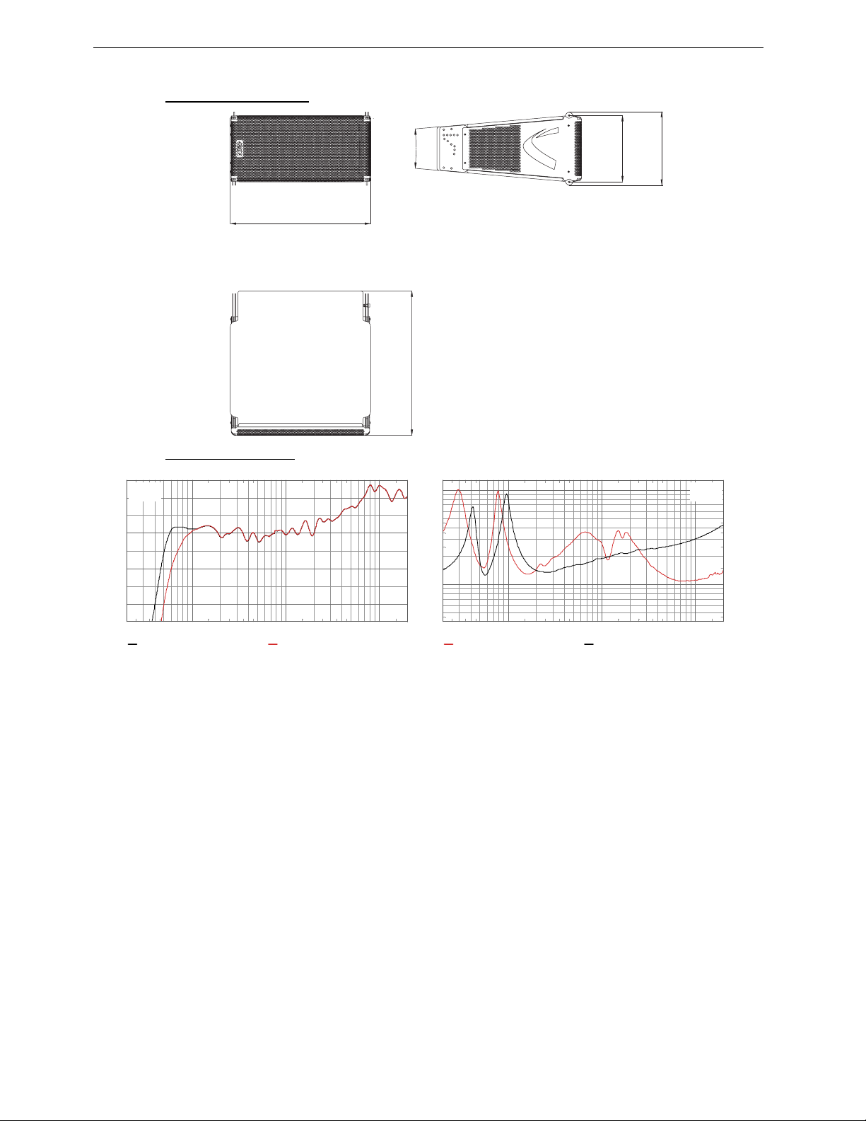
Page 78/97 TECHNICAL SPECIFICATIONS
9.1.2 GEO D10 Dimensions
[29 1/2"]
744 mm
9.1.3 GEO D10 Diagrams
[dB] L evel, Sound pres sur e
15
10
5
0
-5
-10
-15
-20
-25
20 50 100 200 500 1k 2k 5k 10k 20k
FC: 1 x G eo D10 O verlap, 1/3oct smoothing, v alues scaled FC: 1 x Geo D1 0 C rossover, 1/3oct smoothing, val ues scaled
Freque ncy [ Hz]
10°
750 mm
[29 1/2"]
344 mm
[13 1/2"]
380 mm
[15"]
[ohm] Am plitude l og, Im pedance
100
50
20
10
5
20 50 100 200 500 1k 2k 5k 10k 20k
FC: Geo D1 0 impedance fr ont speaker s FC: Geo D1 0 impedance back speaker s
Freque ncy [ Hz]
Page 79
TECHNICAL SPECIFICATIONS Page 79/97
9.2 GEO SUB Directional Sub-Bass
9.2.1 System specifications
PRODUCT FEATURES GEO SUB
Components 1 x 18” (46cm) long excursion neodymium 8 Ohm drivers
Height x Width x Depth 515 x 744 x 1131 mm (20 1/2” x 29 1/2” x 44 1/2”)
Shape 10° Trapezoïdal
Weight: Net 86 kg (189.6 lbs)
Connectors 2 x NL4MP SPEAKON 4 pole (In & Through)
Construction Baltic birch ply finish with structured black coating.
Front finish Molded Dark Grey Metal Grill.
Flying points Integral flying system .
SYSTEM SPECIFICATIONS GEO SUB with NX242 TDcontroller
Frequency Response @-3dB [a] 38 Hz – 300 Hz
Usable Range @-6dB [a] 35 Hz – 500 Hz
Sensitivity 1W @ 1m [b] 103 dB SPL Nominal
Peak SPL @ 1m [b] 140-143 dB Peak
Dispersion [c] Cardioid pattern over the entire useable bandwidth (two channels of the NX242 are used for the process).
Directivity Index [c] Q = 3.4 & DI = 5.3 dB over the entire useable bandwidth.
Crossover Frequency X-Over Mode = 75 Hz active / Overlap Mode = 300 Hz through NX242 Digital TDcontroller.
Nominal Impedance 2 x 8 Ohms
Recommended Amplifiers 2 amplifier channels are required for directional operation, each rated at 1000 to 2000 Watts into 8 Ohm per
SYSTEM OPERATION
Electronic Controller The NX242 Digital TDcontroller presets are precisely matched to the GEO SUB and include sophisticated
Speaker Cables The front loudspeaker of the GEO SUB is wired 2+ & 2- while the rear loudspeaker is wired 1- & 1+. The GEO
Rigging System [d] Please refer to the user manual before any operation.
As part of a policy of continual improvement, NEXO reserves the right to change specifications without notice.
[a] Response curves and data: anechoic far field above 400 Hz, half-space anechoic below 400 Hz.
[b] Sensitivity & peak SPL: will depend on spectral distribution. Measured with band limited pink noise.
Refers to the specified +/- 3 dB range. Data are for speaker + processor + recommended amplifier combinations.
[c] Directivi ty curves and data: 1/3 octave smoothed frequency response, normalized to on-axis response. Data obtained by computer processing of off-axis
[d] Please refer to the user manual.
Usable range data: frequency response capability with TD crossover slopes removed.
response curves.
& 2 x 12“ (30cm) neodynium drivers
Intercabinet angle adjustments = 0.2°, 0.315°, 0.5°, 0.8°; 1.25°, 2.0°, 3.15°, 5°, 6.3°, 8.0°, 10.0° (logarithmic steps)
channel.
protection systems. Using the CD18 subbass without a properly connected NX242 Digital TDcontroller will result in
poor sound quality and can damage components.
SUB must use separate cab les fro m the main sys tem.
Page 80
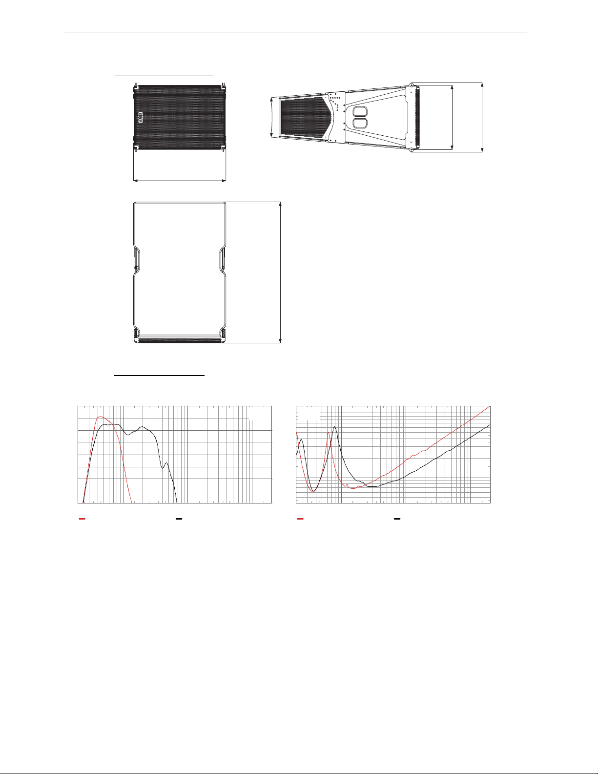
Page 80/97 TECHNICAL SPECIFICATIONS
9.2.2 GEO SUB dimensions
[29 1/2"]
744 mm
9.2.3 GEO SUB diagrams
[dB] L evel, Sound pr ess ure
10
5
0
-5
-10
-15
-20
-25
-30
20 50 100 200 500 1k 2k 5k 10k 20k
F: Geo SUB Crossover, 1/3oct log smoothi ng, values scaled F: Geo SUB Overlap, 1/3oct log smoothi ng, values scaled
Freque ncy [ Hz]
10°
[44 1/2"]
1131 mm
100
[20 1/2"]
[20 3/8"]
515 mm
[ohm] Ampl itude log, Impedance
50
20
10
5
20 50 100 200 500 1k 2k 5k 10k 20k
FC: Geo SUB front impedance FC: Geo SUB rear Impedance
Freque ncy [ Hz]
518 mm
Page 81
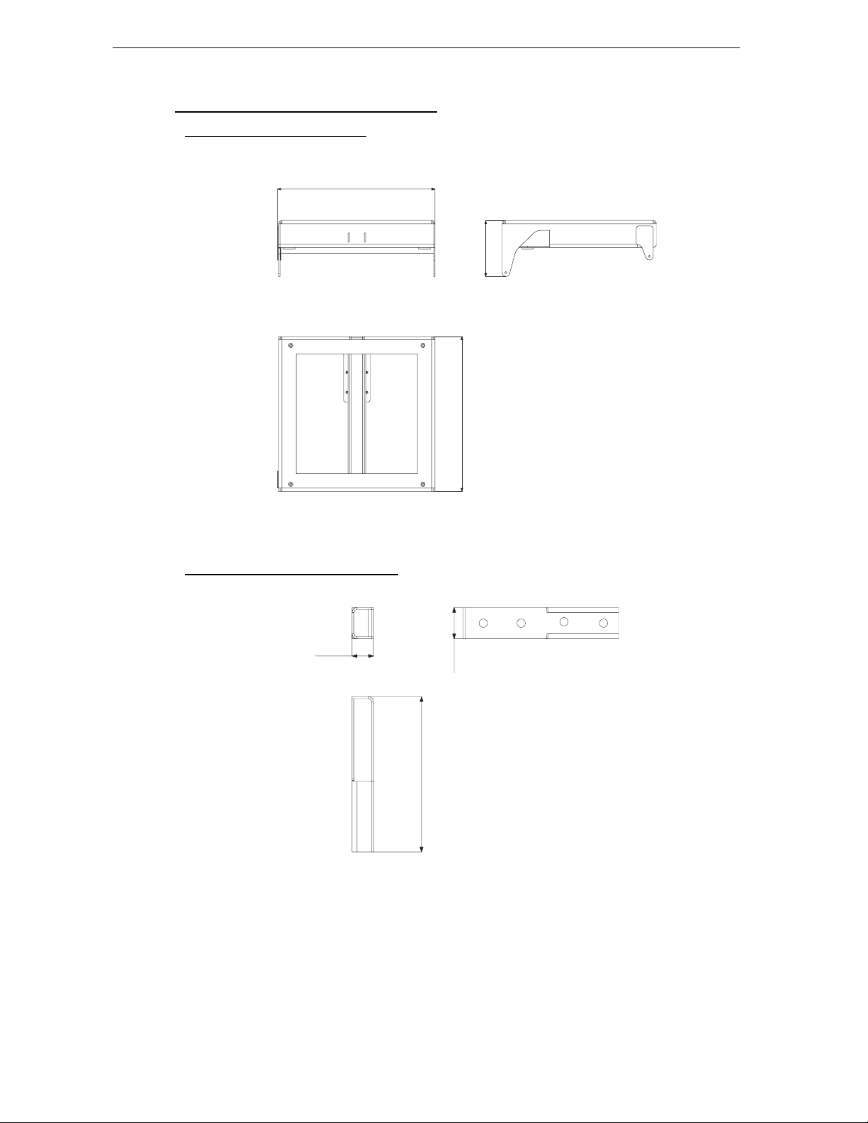
TECHNICAL SPECIFICATIONS Page 81/97
[28"]
9.3 GEO D / GEO SUB Rigging system
9.3.1 GEO D / GEO SUB Bumper
715 mm
WEIGHT : 45 KG / 99.2 LBS
9.3.2 GEO D Short Extension Bar EX1
[27 1/2"]
[10"]
702 mm
254 mm
[2 1/2"]
65 mm
[18 1/2"]
472 mm
[3 1/2"]
95 mm
WEIGHT : 5.3 KG / 11.7 LBS
Page 82
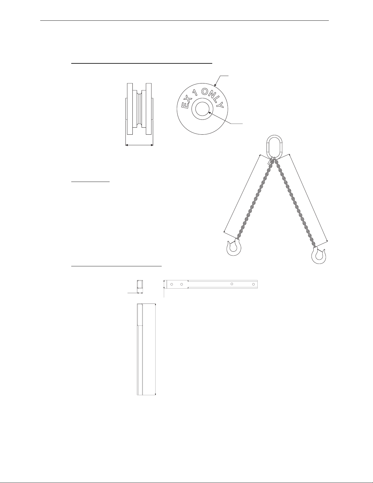
Page 82/97 TECHNICAL SPECIFICATIONS
995 mm
1000 mm
[
6
9.3.3
9.3.4 GEO D – ORP (Compression Wheel for EX1 Only)
51 mm
WEIGHT: 0.250KG / 0.55 LBS
95 mm
25.5 mm
9.3.5 GEO BRIDLE
995 mm
WEIGHT: 3 KG / 6.6 LBS
1000 mm
9.3.6 GEO D Long Extension Bar EX2
2 1/2"]
5 mm
[41 1/2"]
1052 mm
[3 1/2"]
95 mm
WEIGHT: 13.1 KG / 28.9 LBS
Page 83
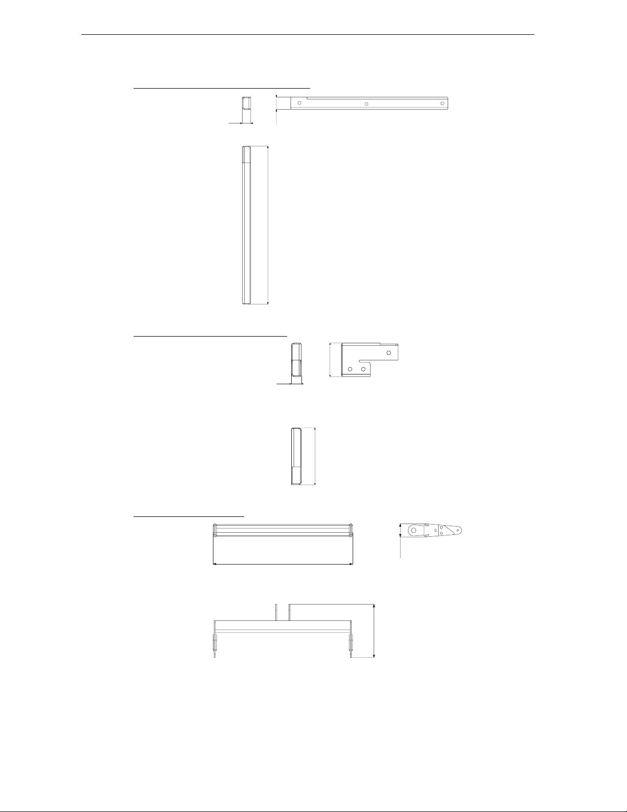
TECHNICAL SPECIFICATIONS Page 83/97
[
6
[
6
9.3.7 GEO SUB Bottom Extension Bar EX3
2 1/2"]
5 mm
[48"]
1225 mm
[3 1/2"]
95 mm
WEIGHT: 16.1 KG / 35.5 LBS
9.3.8 GEO D Front Extension Bar EX4
[8 1/2"]
216 mm
2 1/2"]
5 mm
[14 1/2"]
367mm
WEIGHT: 6.9 KG / 15.2 LBS
9.3.9 GEO D Bottom Bumper
[28 1/2"]
722 mm
WEIGHT: 10.4 KG / 22.9 LBS
[11"]
278 mm
[2 1/2"]
69 mm
Page 84
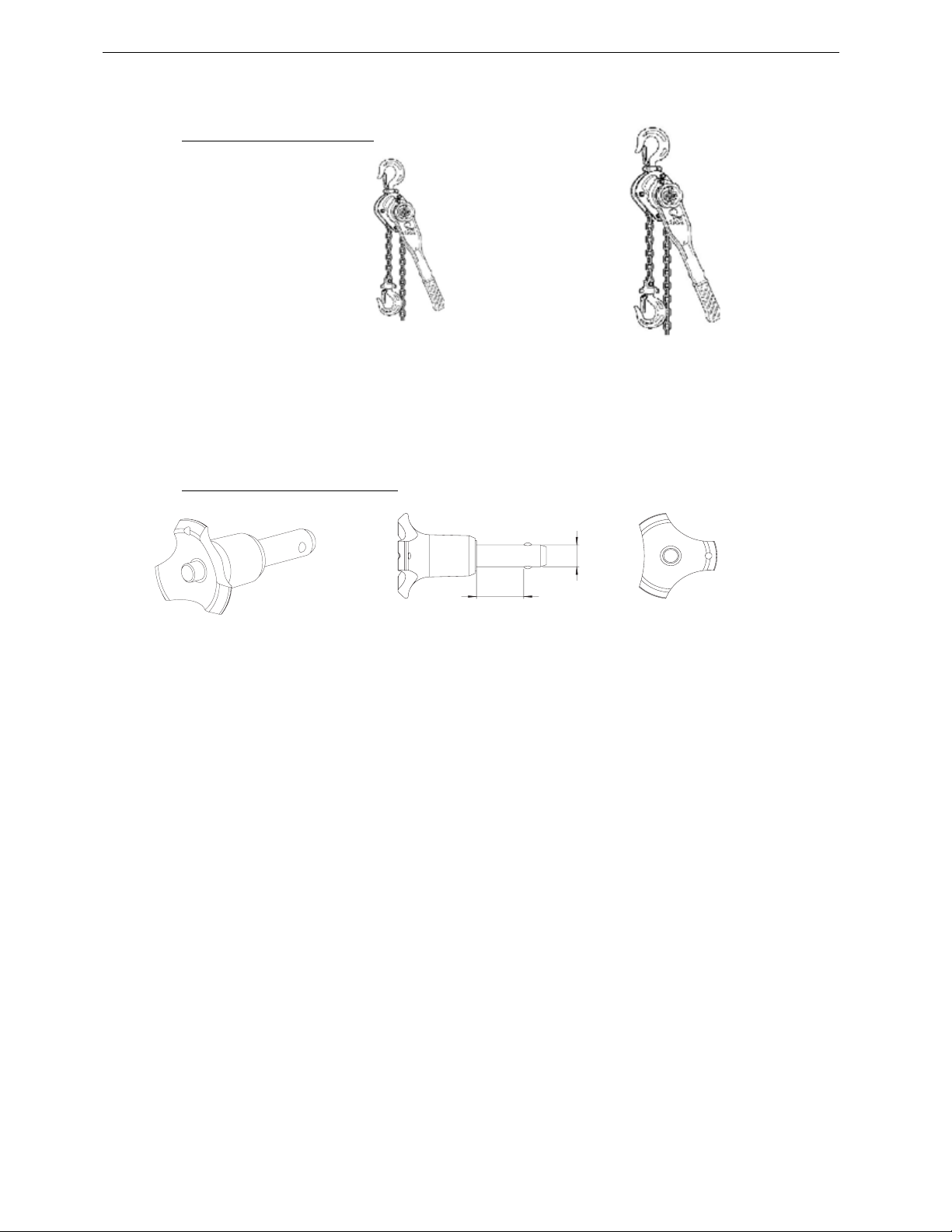
Page 84/97 TECHNICAL SPECIFICATIONS
9.3.10 GEO D Chain Lever Hoists
MAX LOAD 750 KG / 1650 LBS MAX LOAD 1500 KG / 3300 LBS
WEIGHT: 10.3 KG / 22.7 LBS WEIGHT: 23.7 KG / 52.2 LBS
CHAIN LENGTH: 6 M / 16.7 FT CHAIN LENGTH: 9M / 29.5 FT
9.3.11 GEO D / GEO SUB Push-Pins
20 mm
WEIGHT: 0.046 KG / 0.10 LBS
10 mm
Page 85
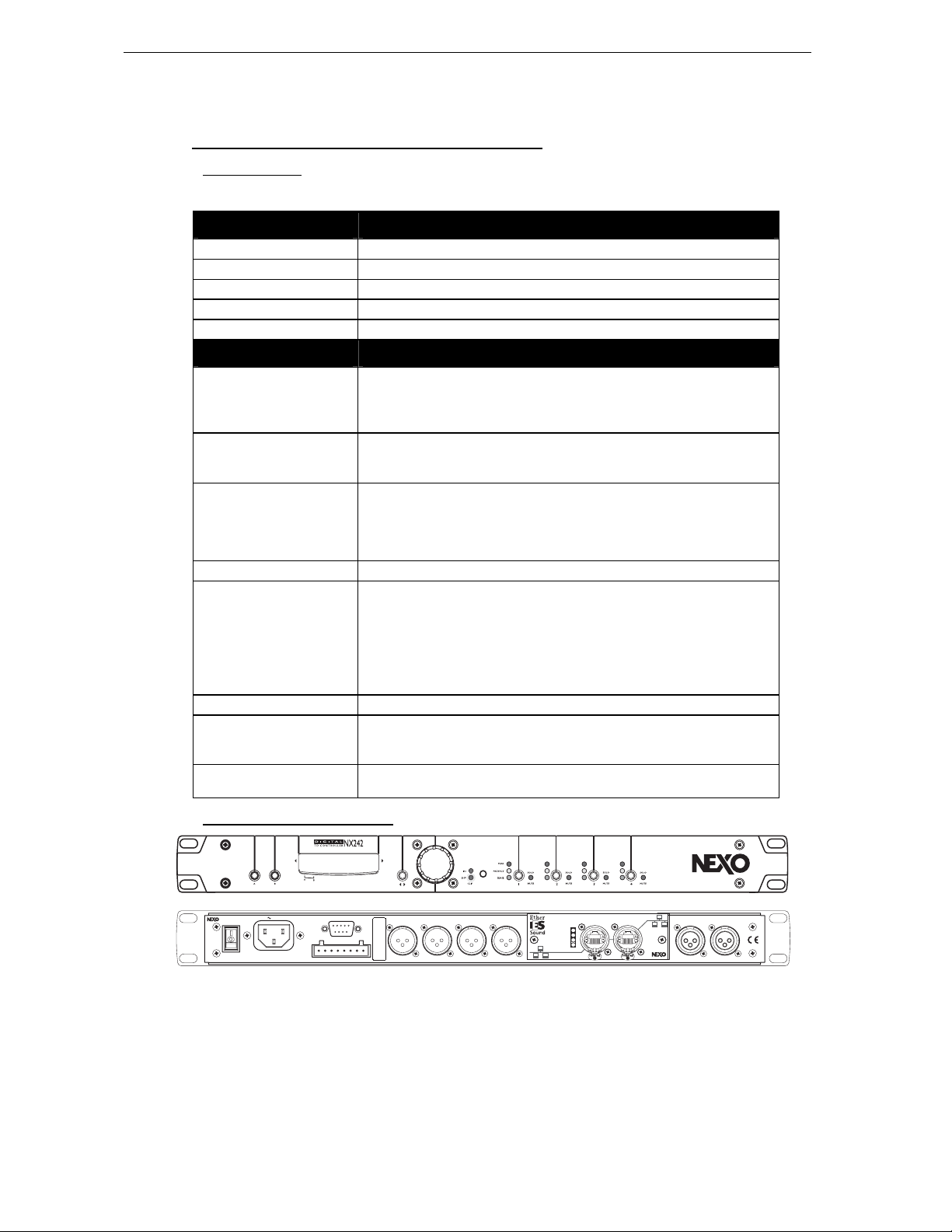
TECHNICAL SPECIFICATIONS Page 85/97
9.4 NX242 TDcontroller with NX-Tension Card
9.4.1 Specifications
SPECIFICATIONS NX242 Digital TDcontroller
Output Level +28 dBu Max. into 600 Ohm load
Dynamic Range 110 dBu
THD + Noise < 0.002% flat setup (for output at 27.5dBu)
Latency time 1.7ms on a flat setup
Power Supply 90V-260V
FEATURES
Audio Inputs 2 Audio Inputs 24 bit converters
Electronically Balanced, 50k Ohm.
2 XLR-3F Connectors.
4 Digital Ethersound Inputs with NXTension ES4 Card
Sense Inputs 4 Amplifier Sense Inputs
Floating 150 kΩ. 18 bit converters
8 Pole Removable Strip Terminal.
Audio Outputs 4 Audio Outputs. 24 bit converters
Electronically balanced, 50 Ohm
4 XLR-3M connectors
4 Digital Ethersound Outputs with NXTension ES4 Card (enabled for compatible amplifiers
only)
Processing 24 bit data with 48-bit accumulator. 200 MIPS
Front Panel
FLASH EPROM Software updates/upgrades, new system setups, available on www.nexo-sa.com
Rear Panel RS 232 connector for serial com
Dimensions & Weight 1U 19" Rack - 230 mm (9") Depth.
Menu A and Menu B buttons
16 characters by 2 lines display
Select Wheel & Enter button ()
IN Clip – DSP Clip red LED’s
Speaker Protection yellow LED for each channel
Individual Mute/Solo buttons and red LED for each channel
Amp. Sense & Peak (green & red) LED’s for each channel
2 x RJ45 connectors with NXTension ES4 Card
1 RJ45 + 2 RJ11 with NXTension CAI Card
4 kg
9.4.2 Front and Rear Panel view
GeoD Passive mode
Crossover 80Hz
115-230V 50 - 60Hz 45W
NX242
MADE IN FRANCE
CAUTION !
To reduce the risk of electric schock, grounding
of the center pin of this plug must be maintained.
+ 4
SENSE INPUT
(from amp terminals)
-
+ 3 -+ 2
RS232
sept.04
03105
NX242 TDcontro
-
-
+ 1
BALANCED OUTPUTS
Channel 4 Channel 3 Channel 2 Channel1 B (RIGHT) A (LEFT)
NXtension-ES
In Rx
In Tx
Out Rx
Out Tx
Out In
FLOATING BALANCED INPUTS
Page 86
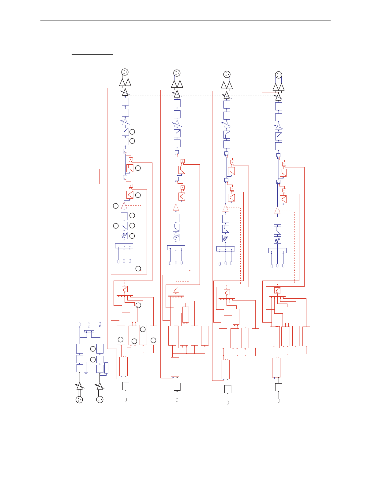
Page 86/97 TECHNICAL SPECIFICATIONS
9.4.3 Block Diagram
OUTPUT
CHANNEL 3
OUTPUT
CHANNEL 2
OUTPUT CHANNEL 1
DACMUTEEQ
Analogue path
Digital Audio
Digital servo & protections
OUTPUT
CHANNEL 4
HEADROOM
DACMUTEEQ
4
NX242 Digital TDcontroller BLOCK DIAGRAM
7 7
6
1
R
SHELVING
A/D EQ
3
R+L
5
2
INPUT VU-METER
HEADROOM
INPUT R
2
L
SHELVING
A/D EQ
INPUT VU-METER
INPUT L
VCA
EQ
1
1
R
Command
displacement
8
DISPLACEMENT 1
Signal
AMP POWER
FALLBACK
13
DELAY 1
2L 3
R+L
ATT/REL.
Command
Disp.
AMP GAIN
AMP VOLTAGE
A/D
5
SENSE 1
3 3
4
PATCH
11
10
Command
PHYSIO 1
Voice Coil Temp.
ChassisTemp
ChassisTemp.
Voice Coil Temp.
9
LF TEMPERATURE
9
HF TEMPERATURE
Command
12
Command
PEAK SIMULATION
DISPLACEMENT 2
1
Command
R 1
Signal
FALLBACK
VCA
EQ
3
R+L 1
displacement
AMP GAIN
AMP POWER
AMP VOLTAGE
A/D DACMUTEEQ
6
DELAY 2
ATT/REL.1
Command
SENSE 2
2
L 1
Command
Voice Coil Temp.
Voice Coil Temp.
Disp.
PATCH 2
PHYSIO 2
ChassisTemp
ChassisTemp.
LF TEMPERATURE 2
Command
HF TEMPERATURE 2
PEAK SIMULATION 2
Command
VCA
EQ
1
R
Command
displacement
DISPLACEMENT 3
Signal
AMP POWER
FALLBACK
DELAY 3
2L 3
R+L
ATT/REL.2
Command
Disp.
AMP GAIN
AMP VOLTAGE
A/D
7
SENSE 3
PATCH 3
Command
PHYSIO 3
Voice Coil Temp.
ChassisTemp
ChassisTemp.
Voice Coil Temp.
LF TEMPERATURE 3
HF TEMPERATURE 3
Command
PEAK SIMULATION 3
Command
VCA
EQ
1
R
Command
displacement
DISPLACEMENT 4
Signal
AMP POWER
FALLBACK
DELAY 4
2L 3
R+L
ATT/REL.3
Command
Disp.
AMP GAIN
AMP VOLTAGE
A/D DACMUTEEQ
8
SENSE 4
PATCH 4
Command
PHYSIO 4
Voice Coil Temp.
ChassisTemp
ChassisTemp.
Voice Coil Temp.
LF TEMPERATURE 4
HF TEMPERATURE 4
Command
PEAK SIMULATION 4
Command
Page 87
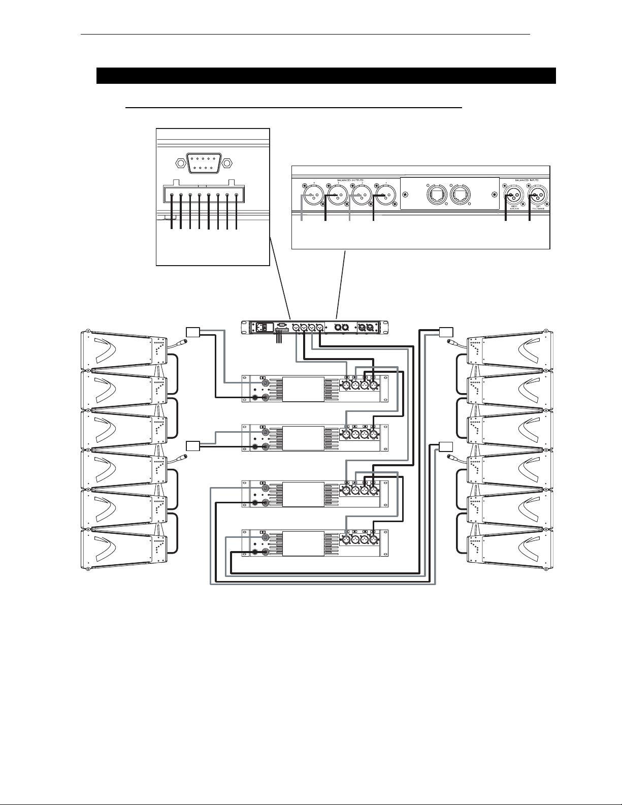
CONNECTION DIAGRAMS Page 87/97
10 CONNECTION DIAGRAMS
10.1 GEO D cluster to amplifiers and NX242 (Stereo passive mode)
FROM AMPLIFIERS
TO AMPLIFIERS
+ 4 - + 3 -
HF +
LF/MF
1 (-) / 2 (+) REAR LF
3 (-) / 4(+) FRONT LF/MF
5 (-) / 6 (+) Not Connected
LF
FRONT
+ 2 - + 1 -
REAR
HF +
LF/MF
FRONT
LF
EP6 F
REAR
HF +
LF/MF
FRONT
STEREO
LF
REAR
HF +
LF/MF
FRONT
LF
REAR
EP6 F
IN
IN
RIGHT
LEFT
AMPLIFIER 1
EP6 F
STEREO
AMPLIFIER 2
STEREO
AMPLIFIER 1
STEREO
AMPLIFIER 2
STEREO PASSIVE MODE
EP6 F
Page 88
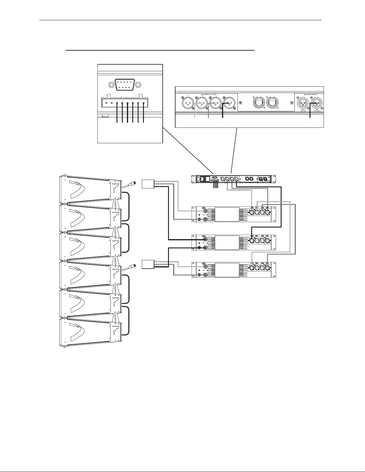
Page 88/97 CONNECTION DIAGRAMS
10.2 GEO D cluster to amplifiers and NX242 (Mono active mode)
FROM AMPLIFIERS
TO AMPLIFIERS
+ 3 - + 2 - + 1 -
HF
LF
LF/MF
FRONT
1 (-) / 2 (+) REAR LF
3 (-) / 4(+) FRONT LF/MF
5 (-) / 6 (+) HF
N.C. HF LF/MF
REAR
EP6 F
FRONT
LF
REAR
STEREO
N.C. IN
EP6 F
FRONT HF + LF/MF
REAR LF
FRONT HF + LF/MF
MONO ACTIVE MODE
STEREO
LINK
STEREO
Page 89
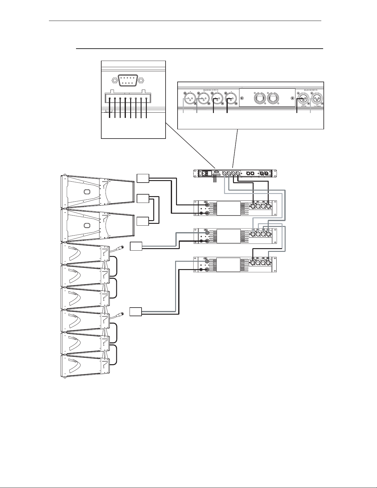
CONNECTION DIAGRAMS Page 89/97
10.3 GEO SUB - GEO D cluster to amplifiers and NX242 (GeoD in Passive Mode)
FROM AMPLIFIERS
TO AMPLIFIERS
+ 4 - + 3-
HF +
LF/MF
FRONT
+ 2 - + 1 -
LF
REAR
SUB
SUB
FRONT
1 (+) / 1 (-) REAR
2 (+) / 2 (-) FRONT
Speakon 4
REAR
HF +
LF/MF
FRONT
LF
SUB
REAR
FRONT
AMPLIFIER 1
SUB
REAR
STEREO
AUX
SUB
IN
GEO D
IN
STEREO
AMPLIFIER 2
EP6 F
STEREO
AMPLIFIER 3
1 (-) / 2 (+) REAR LF
3 (-) / 4(+) FRONT LF/MF
5 (-) / 6 (+) Not Connected
EP6 F
MONO PASSIVE MODE
WITH GEO SUB
Page 90
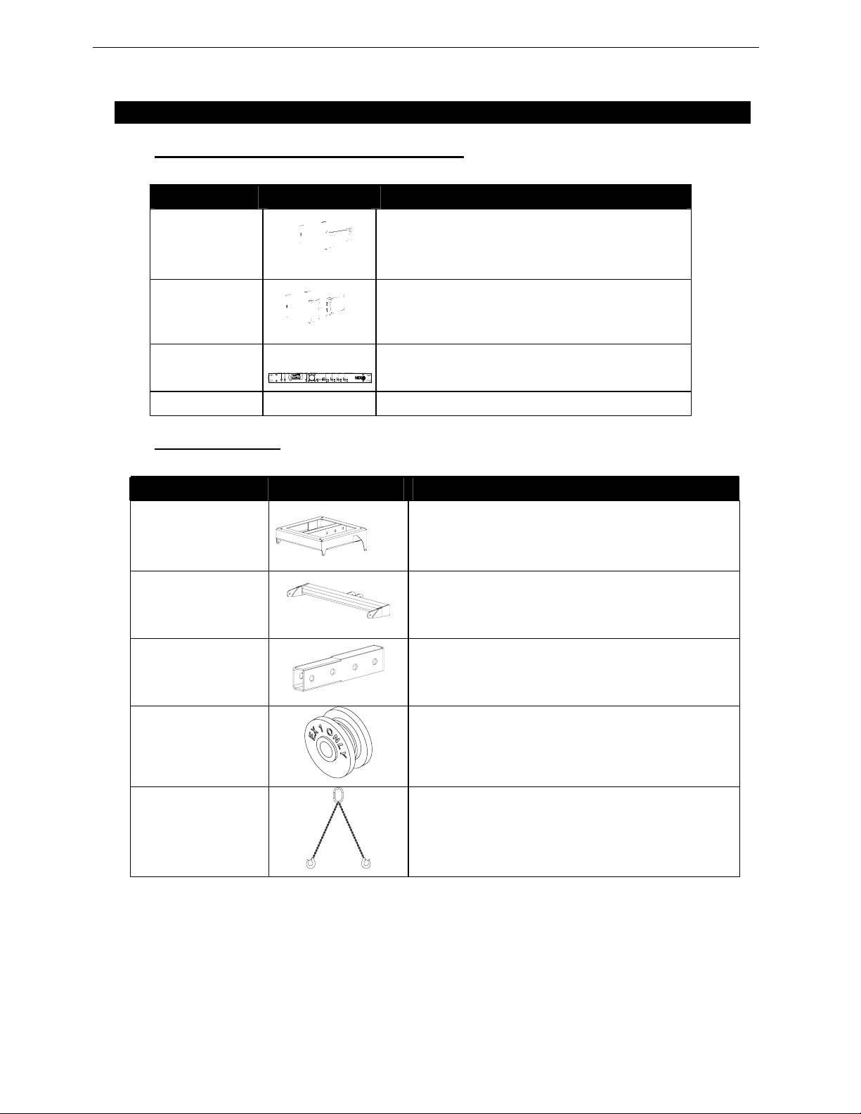
Page 90/97 GEO D SERIES PARTS & ACCESSORIES LIST
11 GEO D SERIES PARTS & ACCESSORIES LIST
11.1 Array Modules & Control Electronics List
MODEL DRAWING DESCRIPTION
GEO D10
GEO SUB
ANX 242
NX-ES4 Ethersound Network & DSP Card for NX242
GEO D 10° Cardioid Main Module
GEO SUB 10° Cardiod Sub-Bass Module
Digital TDcontroller for PS, Alpha and Geo series
11.2 Accessories List
MODEL DRAWING DESCRIPTION
GEOD-BUMPER
Main Geo D Bumper
GEOD-BTBUMPER
GEOD-EXBAR 1
GEOD-ORP
GEO-BRIDLE
Geo D Bottom Bumper
Geo D Extension Bar for GEO D10 Cluster
GEOD-EX1 Wh eel for “One Rigging Point” Mode
Two Legs Bridle for “One Rigging Point” Mode
(One Adjustable Leg)
Page 91
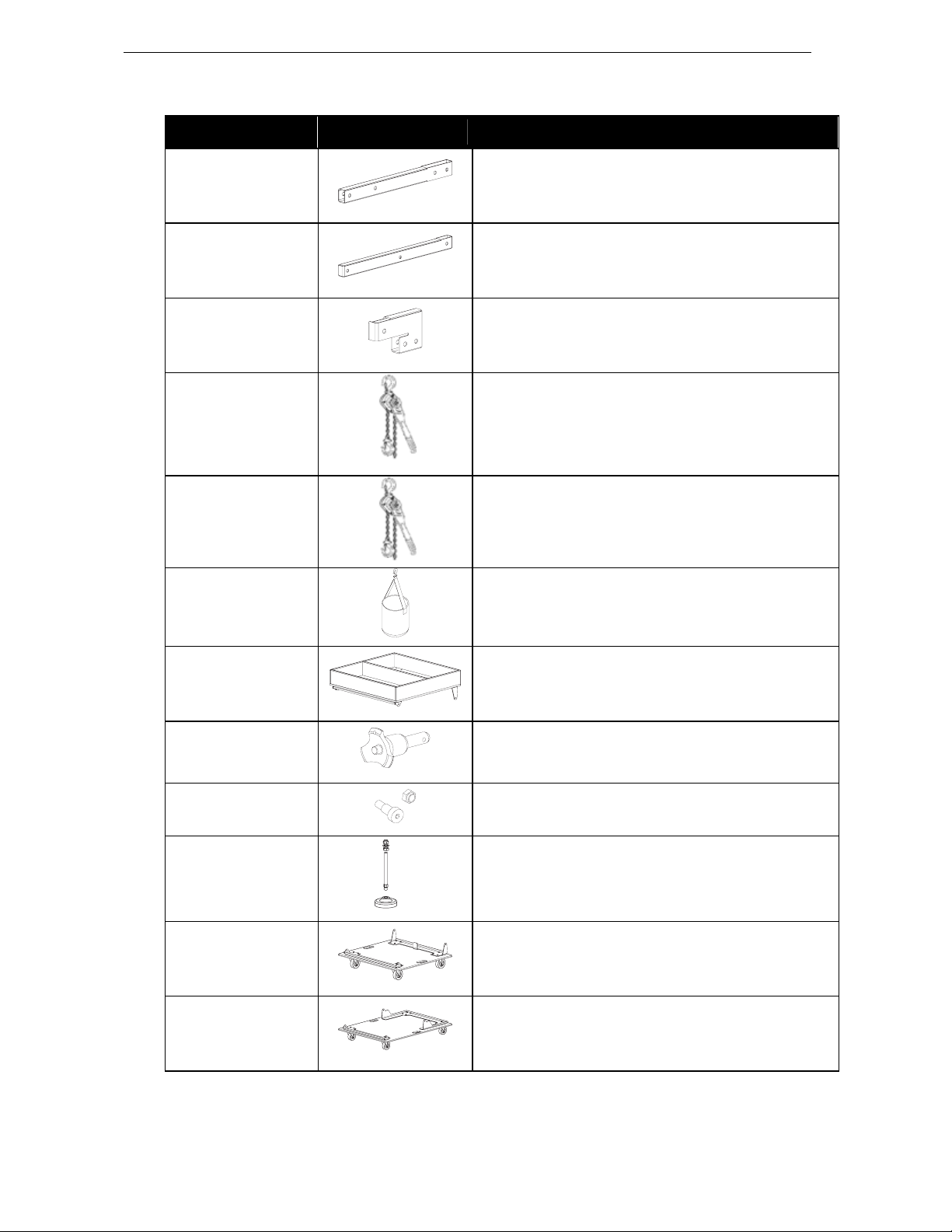
GEO D SERIES PARTS & ACCESSORIES LIST Page 91/97
MODEL DRAWING DESCRIPTION
GEOD-EXBAR 2
GEOD-EXBAR 3
GEOD-EXBAR4
LEVA1500
LEVA750
CHBAG
Geo D Extension Bar for GEO D10 / GEOSUB Cluster
Geo D Bottom Extension Bar for GEOSUB Cluster
Geo D Front Extension Bar for GEO D10 / GEO SUB
Clusters
Chain Lever Hoist 1.5 tonne (9 meters chain length)
Chain Lever Hoist 0.750 tonne (6 meters chain length)
Chain Bag
GEOD-BKM
BLGEOD
GEOD-BNFIX
GEOD-BUDP
GEOD-DOLLY
GEOSUB-DOLLY
6 x
GEO D10 Dolly Storage Tray
GEO D 10mm x 20mm Qui c k Re l ea s e P i n
Kit for fixed installations per flown GEO D
x 4
GEO D Stands for Stacked GEO D Bumper
3 x GEO D10 + 1 x GEOD-BUMPER Dolly
2 x GEOSUB + 1 x GEOD-BUMPER Dolly
Page 92
Page 92/97 GEO D SERIES PARTS & ACCESSORIES LIST
MODEL DRAWING DESCRIPTION
Nylon Cover for
GEOD-DCOVER
GEOD-DCOVER4
GEOSUB-DCOVER
GEOD-RAINCOBP
GEOD-RAINCO
• 3 GEO D10
• 1 GeoD-BKM or 1GEOD-BUMPER
• 1 GEOD-DOLLY
Nylon Cover for
• 4 GEO D10
• 1 GeoD-BKM or 1GEOD-BUMPER
• 1 GEOD-DOLLY
Nylon Cover for
• 2 GEO SUB
• 1 GeoD-BKM or 1GEOD-BUMPER
• 1 GEOSUB-DOLLY
Rain Cover for GEOD-BUMPER
Rain Cover for up to 4 GEOD
BLT-RAP
GEOT-CABLE
GEOT-613F
GEOT-612M
T-RAP for BLGEOD
1m Cable For Geo D10
EP6 Female Connector
AP6 Male Connector
Page 93

USER NOTES Page 93/97
12 USER NOTES
Page 94

Page 94/97 USER NOTES
France
Nexo S.A.
PA du Pré de la Dame Jeanne
F-60128 PLAILLY- FRANCE
Tel: +33 3 44 99 00 70
Fax: +33 3 44 99 00 30
E-mail: [email protected]
BP5
www.nexo-sa.com
 Loading...