

Nexo GEOM1012, GEOM1025 User Manual
User manual
DP2657-01a-DI
GEO M10 Series
GEOM1012 – GEOM1025
Page 2/17 CONTENU
1 CONTENU
1 CONTENU ................................................................................................................................................................... 2
2 WARNINGS ................................................................................................................................................................. 3
3 GEOM10 RIGGING .................................................................................................................................................... 4
4 GEOM10 – ACCESSORIES ....................................................................................................................................... 6
5 DESCRIPTION ........................................................................................................................................................... 9
6 PRESET GEOM10 ................................................................................................................................................... 10
7 ARRAY EQ................................................................................................................................................................. 14
8 MAINTENANCE ....................................................................................................................................................... 15
9 TECHNICAL SPECIFICATIONS ............................................................................................................................ 16
10 USER NOTES ............................................................................................................................................................ 17
EU Conformity declaration
We, NEXO SA
ZA DU PRE DE LA DAME JEANNE
60128 PLAILLY – France
Declare under our sole responsibility that the product Loudspeaker
Type GEOM10
Serial number On the product
Is in conformity with the provisions of the following 2006/95/CE (Low Voltage Directive)
directive including all applicable amendments:
Applied rules and standards: EN ISO 12100, EN 60065
Plailly, February 07th, 2017 Joseph CARCOPINO, R&D Director
WARNINGS Page 3/17
2 WARNINGS
PRECAUTIONS
Do not open the speaker, do not try to disassemble it neither to modify it in any way. The system doesn’t include any user-repairable part.
If the system seems to be malfunctioning or damaged, stop using it at once and have it repaired by a NEXO qualified technician.
Do not expose the system directly to the sun or to the rain, do not immerse it into fluids, do not place objects filled with liquid on the
system. If a liquid gets into the system, please have it inspected by a NEXO qualified technician.
The connection should be performed by qualified technician, by ensuring that power is off.
Operating temperature with temperate climate: 0°C to +40°C (+32°F to +104); -20°C à +60°C (-4°F to +140°F) for storage.
SAFETY INFORMATIONS
Read this manual before using the speaker.
Keep this manual available for further reference.
Observe all warnings and cautions.
Please check the NEXO Web site www.nexo-sa.com to get the most up-to-date version of this manual.
Ensure you are aware of the safety rules applying to rigging, stacking or installing on tripod or speaker stand. Failure to observe these
rules may expose persons to potential wounds or even death.
Only use the system with accessories specified by NEXO.
Please always consult a NEXO-accredited technician if the installation needs architectural works and observe following precautions:
Mounting Precautions:
- Please select screws and mounting location supporting 4 times the system weight.
- Do not expose the system to excessive dust, vibrations, to extreme cold or hot temperatures, to reduce the risk of damaging
components.
- Do not place the system in an unstable position: it could fall accidentally.
- If the system is used on a tripod, please ensure the tripod’s specifications are adapted and that it’s height does not exceed
1.40m/55”. Do not move the tripod with the system in position.
Connection and Powering Precautions:
- Unplug connected cables before moving the system.
- Power off the system before connecting the system.
- When switching on the installation, the amplifier must be powered last; when switching the installation off, shut off the
amplifier first.
- If you work by cold temperatures, progressively raise the level to nominal value during the first minutes of use, to allow
the system components to stabilize.
Please check regularly the system condition.
HIGH SOUND PRESSURE LEVELS
Exposure to very high sound pressure levels may cause permanent hearing losses. Degrees of hearing losses may be different from one
person to another, but almost everybody will be affected if exposed to high sound pressure levels during a long period of time. The OSHA
(Occupational Safety and Health Administration) American Agency specified the following maximal exposures:
Number of Hours
Sound Pressure Level (dBA), Slow Response
8
90
6
92
4
95 3 97
2
100
1 ½
102
1
105
½
110
¼ or less
115
WASTE OF ELECTRIC OR ELECTRONIC EQUIPMENT
This symbol on the product or its packaging indicates that this product must not be treated as household waste.
Instead, it is your responsibility to hand it over to a designated collection point for the recycling of waste electrical
and electronic equipment. By ensuring your waste equipment is recycled, you will help prevent potential
negative consequences for the environment and human health, which could appear if this product was not
recycled. Recycling helps spare natural resources. For more information about the recycling of this product,
please contact your local city office, your household waste disposal service or your reseller.
Page 4/17 GEOM10 RIGGING
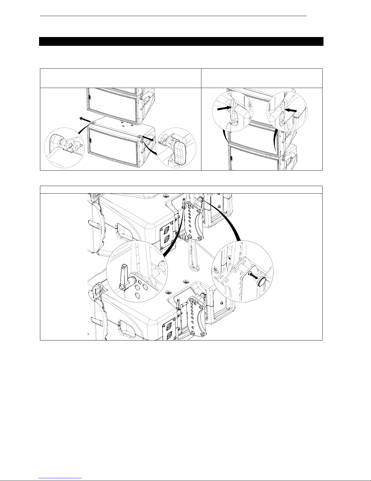
3 GEOM10 RIGGING
Assembly
Front
On both side, pull AutoRigTM in auto lock position.
Position GEOM10 on top, front points will lock
automatically.
Ensure that all AutoRig
TM
systems are locked.
Back
Unlock GEOM10 link bar. Pull on the latch to engage the guide in the slot. Adjust the angle with the quick release pin 0820AV.

GEOM10 RIGGING Page 5/17
Disassembly
Front (stacked or unflown)
On both side, pull AutoRigTM and holding the knob. AutoRigTM remains in the open position.
Back
Remove the quick release pin 0820AV. Unlock the GEOM10 link bar by pulling the latch.
SAFETY: You can replace one of the four screws with an eyebolt (M8), and use a sling (apply thread
lock on the eyebolt).
Page 6/17 GEOM10 – ACCESSORIES
4 GEOM10 – ACCESSORIES
Warnings
All GEOM10 accessories are specifically rated in agreement with structural computations.
Never use other accessories – including push-pins – when assembling GEOM10 cabinets than the ones provided by
NEXO: NEXO will decline responsibility over the entire GEOM10 accessory range if any component is purchased from
different supplier.
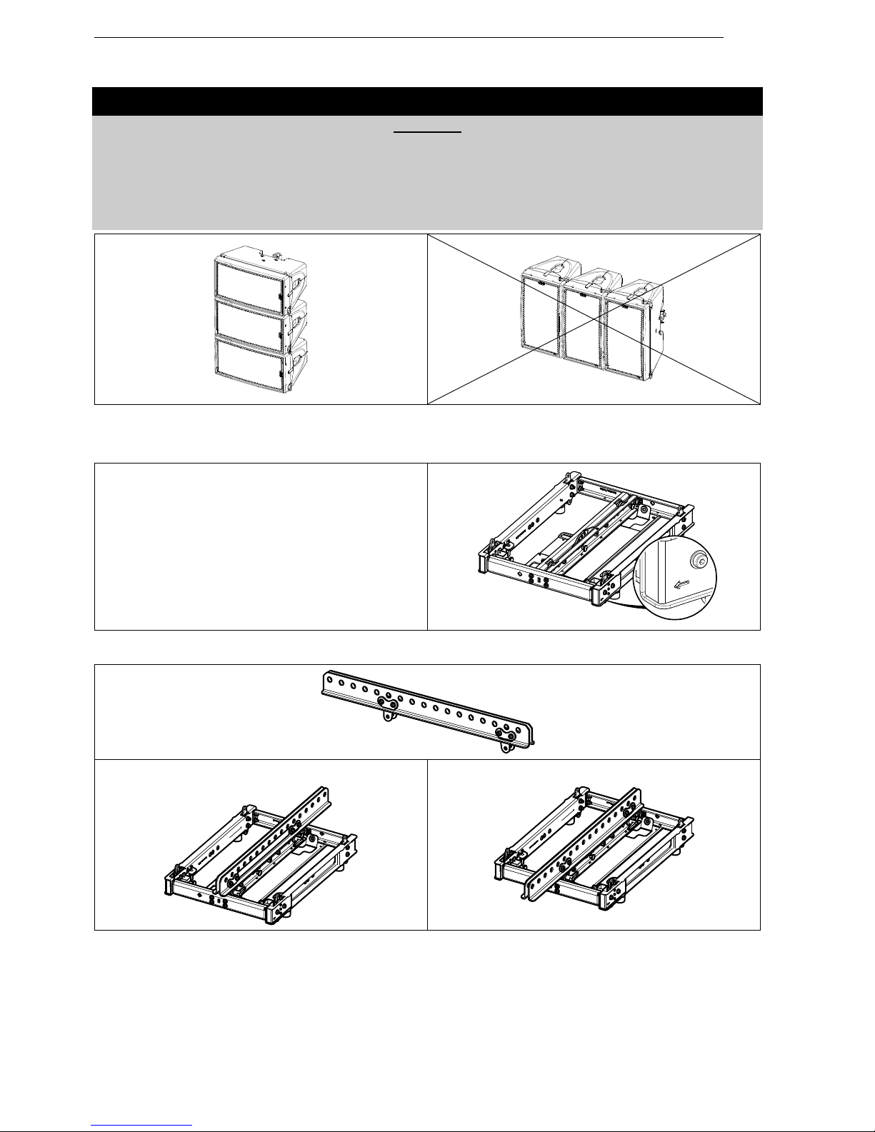
All GEOM10 accessories have been designed so that cabinet are arrayed vertically.
GEOM10 horizontal assemblies as shown in figure below are UNSAFE and STRICTLY PROHIBITED
VNT-BUMPM10
- Rated for a maximum of 12 GEOM10 or 8 MSUB15.
- Maximum quantity for flown vertical cluster is:
N
GEOM10
+ 1.5*N
MSUB15
<= 12
- 2 rigging points 2 points with retractable rings.
- Usable with VNT-EXBARM10 for a one rigging point.
- Ground stack assembly alone, or with VNT-GSTKM10S /
VNT-GSTKM10L.
- 2 locations for laser/ inclinometer.
- On each side, an arrow indicates the front.
VNT-EXBARM10
Negative tilt
Positive tilt
 Loading...