


ALPHA SERIES
Alpha M3 & M8
Alpha Em & EF
B1-18 & B1-15
S2 Sub-bass
User Manual

PAGE 2/37
INTRODUCTION
ALPHA SERIES USER MANUAL V1.0
DATE: 14/01/00 18:27
INTRODUCTION 3
ALPHA SERIES DESCRIPTION 3
LOUDSPEAKERS 3
NEXO TDCONTROLLERS 4
THE X-BOW FLYING SYSTEM 4
GENERAL SET-UP INSTRUCTIONS 5
SPEAKER WIRING 5
FLYING THE SYSTEM 6
TDCONTROLLERS S ETTI N GS 9
INITIAL SET-UP PRECAUTIONS 10
ALPHA ARRAYS - SOME BASIC RULES 11
ALPHA S2 PLACEMENT 11
SPL VERSUS FREQUENCY 11
SPL VERSUS DISTANCE 11
DIRECTIVI TY - COV ERAGE 14
AMPLIFIERS 16
POWER 16
CURRENT RATING 16
AMPLIFIER G AIN S 16
GAIN VALUE 17
ADVANCED PROTECTIONS 17
PASSIVE CROSSOVER FUSES 18
TECHNICAL SPECIFICATIONS 19
ALPHA S2 19
ALPHA B1-15 / B1- 18 20
ALPHA M3 / M8 21
ALPHA EM / EF 22
DIRECTIVI TY TABLES 23
CURVES 24
ALPHA S2 24
ALPHA B1-18 24
ALPHA B1-15 24
ALPHA M3 25
ALPHA M8 28
ALPHA EM 31
ALPHA EF 31
DIMENSIONS 34
TRANSPORT 35
CONNECTION DIAGRAMS 36

PAGE 3/37
INTRODUCTION
ALPHA SERIES USER MANUAL V1.0
DATE: 14/01/00 18:27
INTRODUCTION
Thank you for selecting NEXO Alpha Series. This manual is intended to provide you with
necessary and useful information about your Alpha System:
• S2
• B1-15, B1-18
• M3, M8
• EM, EF
Please devote some attention to reading this manual. A better understanding of some specific
features of the Alpha Series will help you to operate your system to its full potential.
This manual is intended to be com prehensive, and we hope that it will satisfy your requirements.
Should you require further information, please contact your NEXO agent.
Alpha Series description
Loudspeakers
The Alpha range includes the following speakers:
• The S2 Sub-bass is a double 18-inch r esonator loaded sub-bass, dedicated to very low
frequency reproduction (< 80 Hz).
• The B1-15 & B1-18 are com plex loaded (bass-reflex & exponential horn) bass cabinets;
the B1-15 houses one 15-inch driver, while the B1-18 houses one 18-inch driver;
frequency response ranges from 40 Hz up to 200 Hz.
• The Mid-high M3 & M8 are concentric horn cabinets dedicated to the 200 Hz - 20 kHz
frequency range reproduction; the MF range is handled by two exponential horn loaded
10-inch drivers whose response is optimised by two Nexo designed phase plugs; the HF
range is handled by one constant dire ctivity horn loaded two-inch Neodymium driver. M3
coverage is 35° (H) x 35°(V), M8 75° (H) x45° (V).
• The Mid-high EM forms par t of the re cently introduced Alpha E Series; its size and power-
rating is smaller than that of the Alpha M3 & M8; the mid range is handled by an
exponential horn loaded 10’’ driver, while the HF range is handled by a constant directivity
horn loaded ceramic 2’’ driver. Alpha EM coverage is 75°x30°.
• The compact EF is dedicated to the full audio range reproduction 40 Hz – 20 kHz; it
consists of one EM and one B1-18 stacked in a monoblock compact format.
Alpha cabinet formats are designed for optimal array assembly (see section “D
IMENSIONS” p.34); all
the cabinets have the same width and depth; height is in multiples of 200 mm UNITS.
• Six UNITS (1200 mm): Alpha S2, Alpha EF.
• Four UNITS (800 mm): Alpha B1-18.

PAGE 4/37
ALPHA SERIES DESCRIPTION
ALPHA SERIES USER MANUAL V1.0
DATE: 14/01/00 18:27
• Three UNITS (600 mm): Alpha B1-15, Alpha M3, Alpha M8.
• Two UNITS (400 mm): Alpha EM.
Nexo TDcontrollers
The Alpha Series speakers are associated with the NX241 Digital TDcontroller, which can be
configured to provide compr ehensive control of the above, mentioned cabinets. For a complete
description of this unit please ref er to the "NX241 User Manual". You may also use one of the
following analogue TDcontrollers that preceded the NX 241. Pleas e ref er to the c orr es ponding user
manual or contact your NEXO agent for more information on these products.
• Sub TDcontroller for use with Alpha S2;
• Alpha TDcontroller for use with Alpha B1-15, B1-18, M3 & M8;
• AlphaE TDcontroller for use with Alpha B1-18, EM & EF;
This manual will only refer to the NX241 T Dcontroller. Please remember that the NX241 Digital
TDcontroller is a software-based product for which regular updates will be published. Please
consult the NEXO web site for the latest software releases.
The X-BOW flying system
The design of the X-BOW flying system has been optimised for the dispersion specifications of the
Alpha range, its mechanical characteristics match accurately the acoustical properties of the
speakers.
The concept of this flying system enables eff icient array assembly, with minimum space between
cabinets, thus reducing edge diffraction.
The X-BOW flying system includes four main components, references are:
• ALXBOW: main chassis (1);
• ALXKIT: hinge (1) and cable links (2);
• ALXBRIDLE: D-ring (1) and leg chains (3);
• ALXCASE: flight-case for a complete X-BOW flying kit (capacity: 4 X-BOWs).
PAGE 5/37
GENERAL SET-UP INSTRUCTIONS
ALPHA SERIES USER MANUAL V1.0
DATE: 14/01/00 18:27
General Set-up Instructions
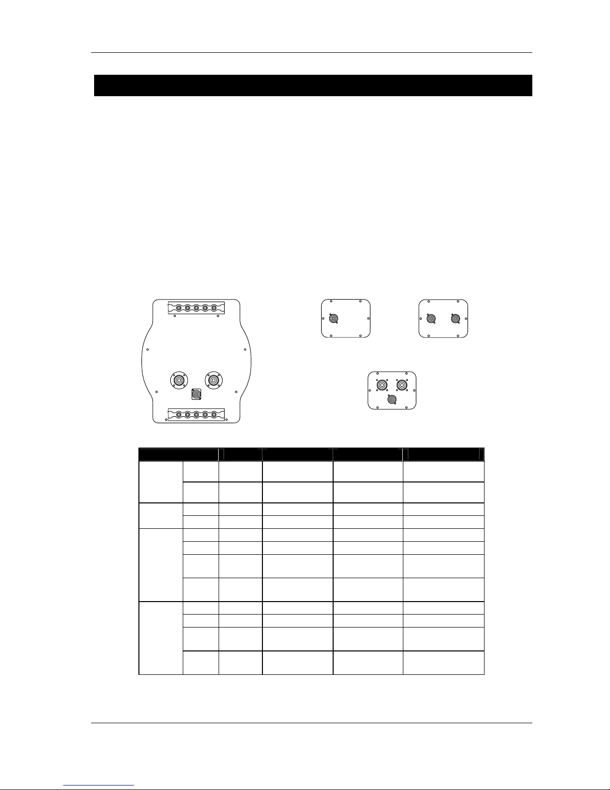
Speaker Wiring
Connectors
The loudspeakers are c onnected via SPEAKON c onnectors , NL4FC and NL8FC (not s upplied). A
wiring diagram is pr inted on the c onnec tion panel located on the bac k of each cabinet. The pins of
the SPEAKON sockets are identified in/out and connected in parallel within the enclosures. A
single 8-conductor cable carries all four bands required by the Alpha M3/B1/S2 system and the
cabinet connectors allow all three types of cabinet to be saf ely linked at the loudspeaker end. (See
Connections Diagrams at the end of this manual).
NB: The Alpha S2 back panel features only one 4- pin SPEAKON connector in order to prevent
accidental parallel connection: very few amplifiers are able to drive such low impedance loads at
the required power level.
CONNECTOR
S2 B1-15 / B1-18 M3 / M8 EM / EF
1±
In / Out
VLF
To VLF (S2) To VLF (S2) To VLF (S2)
SP4
#1
2±
Not
connected
In / Out LF (B1) To LF (B1) To LF (B1)
1±
- To VLF (S2) - -
SP4
#2
2±
- In / Out LF (B1) -
1±
- - In VLF (S2) In / Out VLF (S2)
2±
- - In / Out LF (B1) In / Out LF (B1)
3±
- - In / Out MF
P: In / Out MF+HF
A: In / Out MF
SP8
#1
4±
- - In / Out HF
P: Not connected
A: In / Out HF
1±
- - In VLF (S2) In VLF (S2)
2±
- - In / Out LF (B1) In / Out LF (B1)
3±
- - In / Out MF
P: In / Out MF+HF
A: In / Out MF
SP8
#2
4±
- - In / Out HF
P: Not connected
A: In / Out HF
P = MF-HF passive / A = MF- HF a ctive
S2
B1/15
B1/18
M3
M8
EM
EF
PAGE 6/37
GENERAL SET-UP INSTRUCTIONS
ALPHA SERIES USER MANUAL V1.0
DATE: 14/01/00 18:27
Cables
Nexo recommends the exclusive use of multi-conductor cables to connect the system: the cable kit
is compatible with all the cabinets, and there is no possible confusion between VLF, LF, MF and
HF sections.
Cable choice consists mainly of selecting the correct cable section (s ize) in relation to the load
resistance and the c able length. Too small a c able section will increase its serial resis tance; this
would induce power-loss and response variations (damping factor).
For a serial resistance less or equal to 4% of the load impedance (damping factor = 25), the
maximum cable length is given by:
L
max
= Z x S S in mm2, Z in Ohm, L
max
in meters
The table below indicates these values, for 3 common sizes.
Load Impedance (Ω) 2 3 4 6 8 12 16
Cable section Maximum Length (meters)
1,5 mm² (AWG #14) 3 4.5 6 9 12 18 24
2,5 mm² (AWG #12) 5 7.5 10 15 20 30 40
4 mm² (AWG #10) 8 12 16 24 32 48 64
IMPORTANT NOTE: Long speaker cables induce capacitive effects that impair the quality of audio
signals. If long speaker cables must be used, ensure that they do not remain coiled while in use.
Flying the System
Alpha Series loudspeakers are equipped with steel anchor plates that can be fitted with NEXO XBOW flying accessories. The X-BOW Flying Manual must be thoroughly read before flying
the system.
The following points are designed to remind the user of safe practice when flying the X-BOW
system. They cannot address every possible circumstance in which the system might be deployed;
therefore the user must always apply his or her k nowledge, experience and comm on sense. If in
any doubt, seek advice from your NEXO agent.
Flown Systems Safety
• Always inspect all the X-BOW components and cabinet Fly Rails for damage before
assembly. Pay special attention to the lifting points, trom bone sock ets and safety clips. If
you suspect that any of the components are damaged or defec tive, DO NOT USE THE
AFFECTED PARTS. Contact your supplier for replacements.
• Read the X-BOW Flying manual carefully. Also, be familiar with the manuals and safe
working procedures for any ancillary equipment which will be used with the X-BOW
system such as hoists, steel wires and other rigging components.
• Ensure that all local and National regulations regarding the saf ety and operation of flying
equipment are understood and adhered to. Information on these regulations can usually
be obtained from Local Government Offices.
• When deploying the X -BOW system always wear protective headwear, footwear and eye
protection.

PAGE 7/37
GENERAL SET-UP INSTRUCTIONS
ALPHA SERIES USER MANUAL V1.0
DATE: 14/01/00 18:27
• Do not allow inexperienced persons to handle X-BOW flying systems. Installation
personnel should be trained in loudspeaker flying techniques and should be fully
conversant with this manual.
• Ensure that motor hoists, hoist control systems and ancillary rigging components are
currently certified as safe and that they pass a visual inspection prior to use.
• Ensure that public and personnel are not allowed to pass beneath the system dur ing the
installation process. The work area should be isolated from public access.
• Never leave the system unattended during the installation process.
• Do not place any object, no m atter how small or light, on top of the system during the
installation procedure. The object m ay fall when the system is f lown and is likely to cause
injury.
• Secondary safety steels must be installed once the system has been flown to the
operating height. Secondary steels must be fitted irres pec tive of the loc al saf ety standards
applicable to the territory.
• Do not fly the system over areas to which the audience has access.
• Ensure that the system is secure and prevented from pivoting about the motor hoist. Avoid
any form of dynamic loading to the assembly.
• NEVER attach any item to the X-BOW other than the NEXO X-BOW accessories.
• When flying outdoor systems ensure that the system is not exposed to wind or snow loads
and is protected from rainfall.
• The X-BOW requires regular inspec tion and testing by a competent test centre. NEXO
recommend that the s ystem is load tes ted and cer tif ied annually or more frequently if local
regulations require.
• When de- rigging the system ensure that the sam e duty of care is given to the procedur e
as for the installation. Pack X-BOW components carefully to prevent damage in transit.
• Correct training is fundamental to safe practise when working with loudspeakers flying
systems. NEXO recom mend that us ers contac t local industry associations f or inform ation
on specialist course. Information for UK and International training agencies can be
obtained by contacting:
• The Production Services Association (PSA),
School Passage,
Kingston-upon-Thames,
KT1 SDU Surrey,
ENGLAND
Telephone: +44 (0) 181 392 0180
Ground Stack Safety
Statistically, many more injuries occur due to unstable ground stacked PA systems than those
associated with flown systems. There are s everal reasons for this fact, however the m essage is
clear:

PAGE 8/37
GENERAL SET-UP INSTRUCTIONS
ALPHA SERIES USER MANUAL V1.0
DATE: 14/01/00 18:27
• Always survey the supporting structure upon which a ground stack is to be built. Always
look beneath PA wings to inspect the deck suppor t and if necessary ask for the stage
scrims and dressings be removed to allow access.
• X-BOW components should be used to stabilise ground stacks and to ensure that
cabinets remain securely registered to eac h other. The X- HINGE can be used to connect
Alpha cabinets both vertically and horizontally at the rear and horizontally at the front
edge. In addition the Fly Track can be used as a connection point f or a safety wire to a
secondary structure.
• If the stage surface slopes, as it does in some theatres, ensure that the system is
prevented from sliding forwards due to vibration. This may require the fitting of timber
battens to the stage floor.
• For outdoor systems ensure that that the system is protected from wind forces which
might cause the ground stac k to become unstable. W ind forc es can be huge, especially
upon large systems, and should never be underestimated. Observe meteorological
forecasts, calculate the lik ely effect upon the system prior to erection and ensure that the
system is secured appropriately.
• Take care when stacking cabinets. Always employ safe lifting procedures and never
attempt to build stacks without sufficient personnel and equipment.
• Never allow anyone, whether operators, artists or mem bers of the public to clim b onto a
ground stacked PA system. Anyone who needs to climb over 2m high should be fitted with
suitable safely equipment including a clip-on harness. Please refer to local Health and
Safety legislation in your territory. Your dealer can help with advice on access to this
information.
• Apply the same attention to all safety matters when de-stacking systems.
• Be aware that safety procedures are as important in the truc k and in the warehouse as
they are at the venue.

PAGE 9/37
GENERAL SET-UP INSTRUCTIONS
ALPHA SERIES USER MANUAL V1.0
DATE: 14/01/00 18:27
TDcontrollers settings
The Alpha Series c abinets will not perf orm c orrectly without their associated T Dcontrollers . Sound
quality and reliability are totally dependent on the correct use of the TDcontrollers, in association
with the Nexo instructions, provided.
All manuals & associated technic al notes must be r ead before set-up. Please contact your NEXO
agent for any literature inquiry.
NX241 Digital TDcontroller
The digital NEXO NX241 controller is able to drive the entire current Nexo range (PS & Alpha
series). The following set-ups are supported (at the time of publication).
Alpha Series
ALPHATD B1+M3
Configure Input A to drive a 3-Way Alpha System.
ALPHATD S2+B1+M3
SubTD S2-63Hz
Configure Input A to drive a 4-Way Alpha System.
ALPHATD S2+B1+M3
SubTD S2-80Hz
Configure Input A to drive a 4-Way Alpha System.
ALPHATD S2+B1+M3
S2-63Hz AUX inB
Configures Input B (right) to drive the SUB channel independently.
ALPHATD S2+B1+M3
S2-80Hz AUX inB
Configures Input B (right) to drive the SUB channel independently.
Alpha E Series
AlphaE STEREO
Configures 2 passive Alpha EM + 2 B1-18 (or 2 Alpha EF) in stereo.
AlphaE MONO
Configures Input A to drive 1 passive Alpha EM + B1-18 + S2 sub
cabinet. (Channel 4 is unused).
Very important:
Due to the DSP processing time, analogue Sub TDcontroller / Alpha TDcontroller /
AlphaE TDcontroller are incompatible with the Digital NX241and should never be
used in conjunction to control cabinets within the same array.

PAGE 10/37
GENERAL SET-UP INSTRUCTIONS
ALPHA SERIES USER MANUAL V1.0
DATE: 14/01/00 18:27
Initial Set-up Precautions
When running up a system particularly one which includes brand new cabinets for the first time the
power should be increased slowly to approximately 50% and the system operated at this level f or
two hours. During the following two hours of operation the power level should be limited to
approximately 75%. This procedure allows the adhesives and suspensions within the loudspeaker
components to stabilise and will extend their working life.
In all cases, it is advisable to connec t the loudspeakers only after all the other com ponents have
been wired and are operating correctly. This is particularly important for the amplifiers and the
TDcontroller. It is a good practice to turn down all the amplifier gains before connecting the
cabinets and then turn them up again individually with a medium level music sourc e fed into the
system. The sens e LEDs of the corresponding TDcontroller channel should light up accordingly.
This will help to locate cabling errors, par ticularly channel line inversions, which would disable the
TDcontroller protections and may invalidate the warranty.
IMPORTANT
If more than one amplifier is being driven from an output of the NX241 controller only those
amplifiers which are not connec ted
to sense inputs may be attenuated. If the sensed amplifier is
attenuated and the slave amplifiers are not severe system damage will result!

PAGE 11/37
ALPHA ARRAYS - SOME BAS IC RULES
ALPHA SERIES USER MANUAL V1.0
DATE: 14/01/00 18:27
Alpha Arrays - Some Basic Rules
The concept of arraying speakers derives from two requirements:
• Increased sound pressure level;
• Extended coverage area.
Array behaviour is very complex, and a bad design can lead to very poor results. The Alpha
system was designed to be flexible, allowing the user to optimise the design for a dedicated
situation; its development included a long m eas urem ent progr am on a very large variety of arrays.
Below are some simple rules that the user should respect.
Alpha S2 Placement
The nominal ef ficiency data for Alpha S2 is given for when positioned on the floor (half-s pace).
When flown the acoustic output on axis will be 3 dB lower and if positioned in a corner the acoustic
output on axis will increase by 3 dB.
SPL Versus Frequency
Array frequency response is strongly related to wavelength and array architecture.
• At low frequencies, wavelength being very large in relation to the size of the cabinets,
speakers set close to eac h other will always radiate in phase. The gain in sound pressure
level LGSPL will be of 6 dB per doubling, i.e. if n Alpha S2 or B1 are installed:
LGSPL(20Hz-100Hz) = 20 log10(n)
• In the mid frequency range, the gain depends on the configuration of the array, and will
range from 3 to 6 dB per doubling, i.e. for n Alpha M3, M8, EM or EF:
10 log10(n)
≤ LGSPL(100Hz-1kHz) ≤ 20 log10(n)
• At high frequencies, wavelength being short in relation to the size of the cabinet, the gain
level is smaller : no gain will be obtained for cabinets angled at their nominal cover age,
maximum gain will be obtained for n cabinets pointing in the same direction. Therefore,
the gain will range from 0 to 3 dB per doubling; for n Alpha M3, M8, EM or EF:
0
≤ LGSPL(1kHz-10kHz) ≤ 10 log10(n)
SPL Versus Distance
In open-air conditions, the level of sound at a given distance is related to the following parameters:
• The size and the geometry of the source, which determ ines the shape of the sound wave
(spherical, cylindrical, plane);
• Hygrometry and temperature: viscos ity of the air and ther mal conduction cause an energy
loss increasing with frequency. This phenomenon is referred to as excess attenuation.
PAGE 12/37
ALPHA ARRAYS - SOME BAS IC RULES
ALPHA SERIES USER MANUAL V1.0
DATE: 14/01/00 18:27
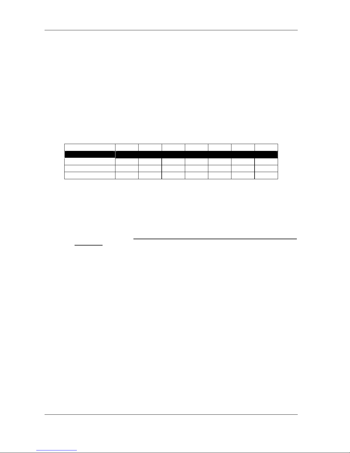
Single Cabinet
Lp(1m) being the sound pressure level at 1m, the level at a distance d (in meters) is given by:
Lp(d) = Lp(1m) - 20 log
10
(d)
• Single Cabinet SPL versus Distance
For example, if the level measured at 1 meter is Lp(1m) = 100 dBSPL, the level at 2 meters will be
94 dBSPL, 80 dBSPL at 10 meters and s o on. Note that under these conditions of sm all source
and open air, the sound pressure level will be decreasing by 6 dB when doubling the distance.
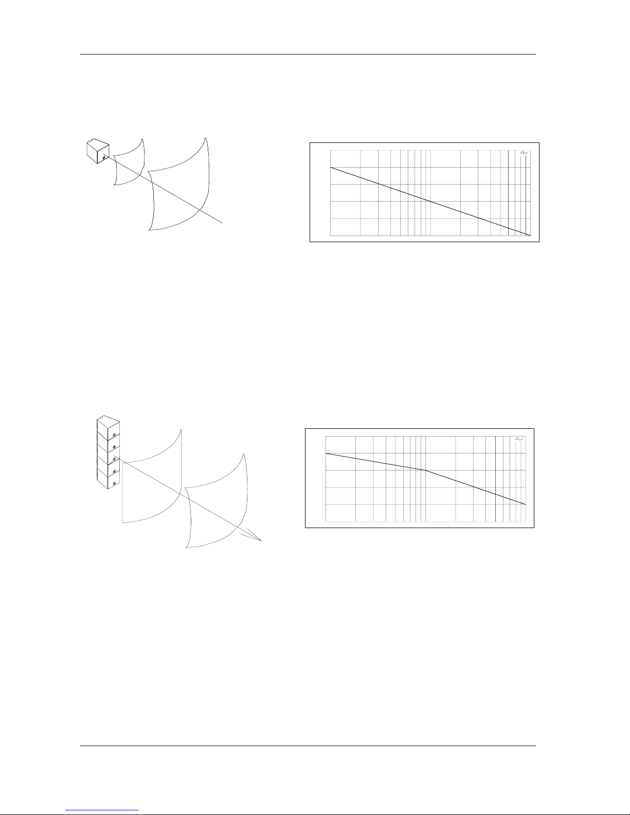
Straight Vertical Array (long throw)
Some open-air applic ations m ight require loud level on a wide f requency range at a long distance.
It is then recommended to stack a large number of Alpha M3/M8/EM vertically. Up to a determined
distance - function of the frequency and the height of the stack -, the sound wave is cylindrical
(3dB/2d); it becomes progressively spherical (6dB/2d) above that distance.
• Transition from cylindrical to spherical wave front
1 10 100
60.000
70.000
80.000
90.000
100.00
110.00
Sound Pressure Level (dBSPL) / distance (meters)
1 10 100
60.000
70.000
80.000
90.000
100.00
110.00
Sound Pressure Level (dBSPL) / distance (meters)

PAGE 13/37
ALPHA ARRAYS - SOME BAS IC RULES
ALPHA SERIES USER MANUAL V1.0
DATE: 14/01/00 18:27
Hygrometry and Temperature - Air Absorption
Under usual conditions, air absorption increas es when relative humidity decreases and increas es
when temperature decreases.
Air absorption gives a linear attenuation, i.e. a constant value of loss of dB per meter: if 1 dB is lost
from 10 to 20 meters, 2 dB will be lost from 20 to 40 meters, 4 dB from 40 to 80 meters and so on...
The tables below list these values for normalised frequencies, and various values of relative
humidity and temperature:
At 20°C:
[dB] loss / meter Up to 1 kHz 2 kHz 4 kHz 8 kHz 16 kHz
RH 20% 0 0.02 0.06 0.20 0.66
RH 50% 0 0.01 0.03 0.08 0.27
RH 80% 0 0.00 0.02 0.05 0.17
Air absorption over a 50m distance; RH=20%-50%-80%
At RH 50%:
[dB] loss / meter Up to 1 kHz 2 kHz 4 kHz 8 kHz 16 kHz
10°C 0 0.01 0.04 0.13 0.43
20°C 0 0.01 0.03 0.08 0.27
30°C 0 0.01 0.02 0.06 0.19
20 100 1k 10k 20k
FREQ(Hz)
-40.00
-30.00
-20.00
-10.00
0.0
10.000
LEVEL(dBV)
AUDIO PRECISION vs 17 JUL 97 19:30:05
Air absorption over a 50m distance; t=10°C-20°C-30°C
The speed of sound C varies with temperature according to the formula below:
273 t20 C +°=
Where t° is the temperature in °C
The delay time between two sources spaced at a distance d is then:
∆t = C/d
20 100 1k 10k 20k
-40.00
-30.00
-20.00
-10.00
0.0
10.000
Frequency (Hz) / Attenuation (dB)
 Loading...