


NEXCOM International Co., Ltd.
Industrial Computing Solutions
Industrial Panel PC
IPPC 1560T/1960T/2160P Series
User Manual
NEXCOM International Co., Ltd.
Published August 2014
www.nexcom.com

Content
Contents
Preface
Copyright .............................................................................................. v
Disclaimer ............................................................................................... v
Acknowledgements ................................................................................ v
Regulatory Compliance Statements ......................................................... v
Declaration of Conformity ....................................................................... v
RoHS Compliance .................................................................................. vi
Warranty and RMA ................................................................................vii
Safety Information .................................................................................. x
Installation Recommendations ................................................................. x
Safety Precautions .................................................................................. xi
Technical Support and Assistance ...........................................................xii
Conventions Used in this Manual ...........................................................xii
Global Service Contact Information ....................................................... xiii
Package Contents ..................................................................................xv
Ordering Information ............................................................................xvi
Chapter 1: Product Introduction
IPPC 1560T Series ...................................................................................1
Specifications .......................................................................................... 2
IPPC 1960T Series ...................................................................................4
Specifications .......................................................................................... 5
IPPC 2160P ............................................................................................. 7
Specifications .......................................................................................... 8
Knowing Your IPPC 1560T Series ..........................................................10
IPPC 1560TP2E-DC Rear Top .............................................................. 10
IPPC 1560TP2E-DC Rear Bottom ........................................................ 10
IPPC 1560TP2E-AC Rear Bottom ........................................................ 11
IPPC 1560TP2E-AC Rear Top .............................................................. 11
IPPC 1560TE Rear Bottom ..................................................................13
IPPC 1560TE Rear Top ........................................................................13
Knowing Your IPPC 1960T Series ..........................................................14
IPPC 1960TP2E-DC Rear Top .............................................................. 14
IPPC 1960TP2E-DC Rear Bottom ........................................................ 14
IPPC 1960TP2E-AC Rear Bottom ........................................................ 15
IPPC 1960TP2E-AC Rear Top .............................................................. 15
Knowing Your IPPC 2160P .................................................................... 17
IPPC 2160P Rear Top .........................................................................17
IPPC 2160P Rear Bottom ...................................................................17
IPPC 1560T Series Rear ...................................................................... 19
IPPC 1960T Series Rear ...................................................................... 20
IPPC 2160P Rear ................................................................................ 21
Mechanical Dimensions .........................................................................22
IPPC 1560TP2E-DC ............................................................................ 22
IPPC 1560TP2E-AC ............................................................................ 23
IPPC 1560TE ...................................................................................... 24
IPPC 1960TP2E-DC ............................................................................ 25
IPPC 1960TP2E-AC ............................................................................ 26
IPPC 2160P ........................................................................................27
Copyright © 2014 NEXCOM International Co., Ltd. All Rights Reserved.
ii
IPPC 1560T/1960T/2160P Series User Manual

Content
Chapter 2: Jumpers and Connectors
Before You Begin ..................................................................................28
Precautions ..........................................................................................28
Jumper Settings ....................................................................................29
Locations of the Jumpers and Connectors ............................................. 30
Jumpers and DIP Switch Settings ........................................................... 31
AT/ATX Power Type Select ..................................................................31
LCD Power Select ..............................................................................31
CCFL Power Select .............................................................................32
Touch Panel Type Select .....................................................................32
CMOS Clear Select ............................................................................33
RI Feature Selection (COM1) ...........................................................33
RI Feature Selection (COM2) ...........................................................34
RI Feature Selection (COM3) ...........................................................34
RI Feature Selection (COM4) ...........................................................35
Dimming Type Select .........................................................................35
LVDS Resolution Select ......................................................................36
PWN Reverse/Function Key Dimming Select .......................................36
Connector Pin Definitions .....................................................................37
External I/O Interfaces ........................................................................ 37
Keyboard/Mouse Ports ...................................................................37
COM 1 and COM 2 Ports ............................................................... 37
COM 3 and VGA Port ....................................................................38
LAN 1 and USB Ports ...................................................................... 38
LAN 2 and USB Ports ...................................................................... 39
Audio Connectors .......................................................................... 39
Connector Pin Definitions .....................................................................40
Internal Connectors ........................................................................... 40
PoE Power Connector ....................................................................40
Power Button ................................................................................. 40
DC Power Button (AT) ....................................................................41
COM 4 ...........................................................................................41
COM 5 ...........................................................................................42
COM 6 ...........................................................................................42
USB Connectors ............................................................................. 43
Speaker-out Connector ..................................................................43
CFast Card Slot ..............................................................................44
SATA Connector .............................................................................44
SATA Connector .............................................................................45
SATA Power Connector ..................................................................45
SATA Power Connector ..................................................................46
LVDS Connector A .........................................................................46
LVDS Connector B .......................................................................... 47
LVDS Panel Inverter Connector ....................................................... 47
Touch Panel Control Connector ......................................................48
SATA/Power LED ............................................................................48
MCU Debug I/F ..............................................................................49
MCU LED Indicator Connector .......................................................49
Function Key-in Connector ............................................................. 50
System FAN2 Connector .................................................................50
System FAN1 Connector .................................................................51
Power Button ................................................................................. 51
Bluetooth Connector ......................................................................52
Digital I/O .......................................................................................52
GPIO .............................................................................................. 53
Bluetooth Connector ......................................................................53
Parallel Port Box Header .................................................................54
Mini-PCIe Connector ...................................................................... 55
Mini-PCIe Connector ...................................................................... 56
Chapter 3: System Setup
Installing a Primary SATA Hard Drive .....................................................57
Installing a Secondary SATA Hard Drive .................................................61
Copyright © 2014 NEXCOM International Co., Ltd. All Rights Reserved.
iii
IPPC 1560T/1960T/2160P Series User Manual

Content
Installing a CFast Card ..........................................................................64
Installing a Mini-PCIe Module ................................................................ 66
Installing a Riser Card ............................................................................81
Installing a PCI Card ..............................................................................86
Installing a CPU and SO-DIMM .............................................................. 88
Panel Mounting ....................................................................................92
Chapter 4: BIOS Setup
About BIOS Setup ................................................................................. 94
When to Configure the BIOS .................................................................94
Default Configuration ........................................................................... 95
Entering Setup ...................................................................................... 95
Legends ................................................................................................ 95
BIOS Setup Utility .................................................................................. 97
Main .................................................................................................97
Advanced ......................................................................................... 98
Chipset ............................................................................................109
Boot ................................................................................................ 113
Security ...........................................................................................115
Save & Exit ......................................................................................115
Appendix A: GPI/O Programming Guide.............116
Appendix B: Watchdog Timer Setting.................118
Copyright © 2014 NEXCOM International Co., Ltd. All Rights Reserved.
iv
IPPC 1560T/1960T/2160P Series User Manual

Preface
Preface
Copyright
This publication, including all photographs, illustrations and software, is
protected under international copyright laws, with all rights reserved. No
part of this manual may be reproduced, copied, translated or transmitted in
any form or by any means without the prior written consent from NEXCOM
International Co., Ltd.
Disclaimer
The information in this document is subject to change without prior notice and
does not represent commitment from NEXCOM International Co., Ltd. However,
users may update their knowledge of any product in use by constantly checking
its manual posted on our website: http://www.nexcom.com. NEXCOM shall
not be liable for direct, indirect, special, incidental, or consequential damages
arising out of the use of any product, nor for any infringements upon the rights
of third parties, which may result from such use. Any implied warranties of
merchantability or fitness for any particular purpose is also disclaimed.
Acknowledgements
IPPC 1560T/1960T/2160P is a trademark of NEXCOM International Co.,
Ltd. All other product names mentioned herein are registered trademarks of
their respective owners.
Regulatory Compliance Statements
This section provides the FCC compliance statement for Class B devices and
describes how to keep the system CE compliant.
Declaration of Conformity
FCC
This equipment has been tested and verified to comply with the limits for
a Class B digital device, pursuant to Part 15 of FCC Rules. These limits are
designed to provide reasonable protection against harmful interference when
the equipment is operated in a commercial environment. This equipment
generates, uses, and can radiate radio frequency energy and, if not installed
and used in accordance with the instructions, may cause harmful interference
to radio communications. Operation of this equipment in a residential area
(domestic environment) is likely to cause harmful interference, in which
case the user will be required to correct the interference (take adequate
measures) at their own expense.
CE
The product(s) described in this manual complies with all applicable
European Union (CE) directives if it has a CE marking. For computer systems
to remain CE compliant, only CE-compliant parts may be used. Maintaining
CE compliance also requires proper cable and cabling techniques.
Copyright © 2014 NEXCOM International Co., Ltd. All Rights Reserved.
v
IPPC 1560T/1960T/2160P Series User Manual

Preface
RoHS Compliance
NEXCOM RoHS Environmental Policy and Status
Update
NEXCOM is a global citizen for building the digital
infrastructure. We are committed to providing green
products and services, which are compliant with
European Union RoHS (Restriction on Use of Hazardous Substance in
Electronic Equipment) directive 2011/65/EU, to be your trusted green
partner and to protect our environment.
RoHS restricts the use of Lead (Pb) < 0.1% or 1,000ppm, Mercury (Hg) < 0.1%
or 1,000ppm, Cadmium (Cd) < 0.01% or 100ppm, Hexavalent Chromium
(Cr6+) < 0.1% or 1,000ppm, Polybrominated biphenyls (PBB) < 0.1% or
1,000ppm, and Polybrominated diphenyl Ethers (PBDE) < 0.1% or 1,000ppm.
In order to meet the RoHS compliant directives, NEXCOM has established
an engineering and manufacturing task force to implement the introduction
of green products. The task force will ensure that we follow the standard
NEXCOM development procedure and that all the new RoHS components
and new manufacturing processes maintain the highest industry quality
levels for which NEXCOM are renowned.
The model selection criteria will be based on market demand. Vendors and
suppliers will ensure that all designed components will be RoHS compliant.
How to recognize NEXCOM RoHS Products?
For existing products where there are non-RoHS and RoHS versions, the
suffix “(LF)” will be added to the compliant product name.
All new product models launched after January 2013 will be RoHS compliant.
They will use the usual NEXCOM naming convention.
Copyright © 2014 NEXCOM International Co., Ltd. All Rights Reserved.
vi
IPPC 1560T/1960T/2160P Series User Manual

Preface
Warranty and RMA
NEXCOM Warranty Period
1. NEXCOM makes products in accordance with the Industry standard and,
NEXCOM warrants that all her Industry-grade IPC and System products
will be free from defect in neither material nor workmanship for twentyfour (24) months from the day of invoice issued.
2. For NEXCOM Panel PC product lines (the APPC, MPPC series), they are
also guaranteed against defect in materials and workmanship for the
period of twenty-four (24) months in their motherboard design. For
3rd party parts, it follows with original suppliers’ standard: 12 months
for battery pack and LCD, 24 months for adaptor / add on modules
(including GSM module, RFID module, and antenna).
3. If NEXCOM determines customer’s warranty claim is valid, NEXCOM
will repair or replace product(s) without additional charge for parts and
labor. An extended Warranty Program will extend the warranty period of
the product accordingly.
Warranty Coverage
The warranty applies only to products manufactured or distributed by
NEXCOM and her subsidiaries. This warranty covers all the products/
shipments except for:
1. Any claimed defect, products that have been repaired or modified by
persons who have not been authorized by NEXCOM or, products which
have been subjected to misuse, abuse, accident, improper installation,
or usage not in accordance with the product instruction. NEXCOM
assumes no liability as a consequence of such events under the term of
this warranty.
One example is the replacement of Tablet’s or Hand-held’s LCD display
due to scratching stains or other degradation; these will not be covered
under this warranty.
2. Damages caused by customers’ delivery/shipping of the product
or, product failure resulted from electrical power/voltage shock, or,
installation of parts/components which are not supplied/approved by
NEXCOM in advance.
3. Third-party products:
a. Software, such as the device drivers,
b. External devices such as HDD, printer, scanner, mouse, LCD panel,
battery, and so on,
c. Accessory/parts that were not approved by NEXCOM and,
d. Accessory/parts were added to products after they were shipped
from NEXCOM.
Product will be treated as “Out of Warranty “ if:
a. It expires the warranted 24 months period from the day it was purchased.
b. It had been altered by persons other than an authorized NEXCOM
service person or, which have been subjected to misuse, abuse, accident,
or improper installation.
c. It doesn’t have the original NEXCOM Serial Number labeling for
NEXCOM’s warranty period identification or, tracking.
Copyright © 2014 NEXCOM International Co., Ltd. All Rights Reserved.
vii
IPPC 1560T/1960T/2160P Series User Manual

Preface
RMA that NEXCOM has determined not to be covered by the warranty will
be charged the NEXCOM Standard Repair Fee for the repairing. If a RMA is
determined to be not repairable, customer will be notified and product(s)
may be returned to customer at their request; a minimum service fee may
be charged however.
NEXCOM Return Merchandise Authorization (RMA) Procedure
For the RMA (Return Merchandise Authorization) shipment, customer
is responsible for packaging and shipping the product to the designated
NEXCOM service sites, with shipping charges prepaid by the customer. The
original NEXCOM shipping box should be used whenever possible. NEXCOM
shall pay for the return of the product to the customer’s location. In case of
expedited shipping request, an extra service charge shall be assessed and
the customer is responsible for this extra return shipping charge.
1. Customers should enclose the “NEXCOM RMA Service Form” with the
returned products.
2. Customers need to write down all the information related to the problem
on the “ NEXCOM RMA Service Form “ when applying for the RMA
service; information will help to understand the problem, including the
fault description, on-screen messages, and pictures if possible.
3. Customers could send back the faulty product with or without the
accessories and key parts such as the CPU and DIMM. If the key parts are
included, please be noted clearly within the return form. NEXCOM takes
no responsibility for the parts which are not listed in the return form.
customer registered delivery address will incur an extra shipping charge,
the customer is responsible for paying the extra shipping charges, duties,
and taxes of this shipment.
Product Repairing
1. NEXCOM will repair defective products covered under this limited
warranty that are returned to NEXCOM; if products do prove to be
defective, they will be repaired during their warranty period unless other
warranty terms have been specified.
2. NEXCOM owns all parts removed from repaired products.
3. NEXCOM will use parts made by various manufacturers in performing
the repair.
4. The repaired products will be warranted subjected to the original
warranty coverage and period only.
5. For products returned as defective but, proved to be no defect/fault after
the RMA process, NEXCOM reserves the right to claim for a NDF (No
Defect Found) Service Charge.
6. NEXCOM will issue RMA Report which included Repair Detailed
Information to the customer when the defective products were repaired
and returned.
7. In addition to the above, NEXCOM may authorize Independent/Thirdparty suppliers to repair the defective products for NEXCOM.
4. Customers hold the responsibility to ensure that the packing of defective
products is durable enough to be resistant against further damage due
to the transportation; damage caused by transportation is treated as “
Out of Warranty “ under our Warranty specification.
5. RMA product(s) returned by NEXCOM to any location other than the
Copyright © 2014 NEXCOM International Co., Ltd. All Rights Reserved.
viii
IPPC 1560T/1960T/2160P Series User Manual

Preface
Out Of Warranty Service
There will be a service charge from NEXCOM for the “Out Of Warranty”
product service; they are the Basic Diagnostic Service Fee and the Advanced
Component Replacement Fee respectively. And, if the product can not be
repaired, NEXCOM will either return the product to the customer or, just
scrap it, followed by customer’s instruction.
1. Testing and Parts Replacement
NEXCOM will have the following Handling Charges for those OoW
products that returned:
a. Basic Labor Cost and Testing Fee: as Table listed.
b. Parts Fee: NEXCOM will charge for main IC chipsets such as the N.B.,
S.B., Super-IO, LAN, Sound, Memory, and so on.
c. 3rd-party Device Fee: products replacement for CPU, DIMM, HDD,
Chassis, and UPS.
2. Out of Warranty product will have a three months warranty for the fixed
issues. If the product failed with different problem within 3 months, they
will still incur the service charge of “Out of Warranty”.
3. Out of Warranty “products will not be repaired without a signed PI from
the customer, the agreement of the repair process.
Add-on card, 3rd Party Device and board level repair cost higher than
new product prices, customer can abandon to sign PI to repair and,
please contact with sales to buy new products.
Copyright © 2014 NEXCOM International Co., Ltd. All Rights Reserved.
ix
IPPC 1560T/1960T/2160P Series User Manual

Preface
Safety Information
Before installing and using the device, note the following precautions:
▪ Read all instructions carefully.
▪ Do not place the unit on an unstable surface, cart, or stand.
▪ Follow all warnings and cautions in this manual.
▪ When replacing parts, ensure that your service technician uses parts
specified by the manufacturer.
▪ Avoid using the system near water, in direct sunlight, or near a heating
device.
▪ The load of the system unit does not solely rely for support from the
rackmounts located on the sides. Firm support from the bottom is highly
necessary in order to provide balance stability.
Installation Recommendations
Ensure you have a stable, clean working environment. Dust and dirt can get
into components and cause a malfunction. Use containers to keep small
components separated.
Adequate lighting and proper tools can prevent you from accidentally
damaging the internal components. Most of the procedures that follow
require only a few simple tools, including the following:
▪ A Philips screwdriver
▪ A flat-tipped screwdriver
▪ A grounding strap
▪ An anti-static pad
Using your fingers can disconnect most of the connections. It is recommended
that you do not use needle-nose pliers to disconnect connections as these
can damage the soft metal or plastic parts of the connectors.
Copyright © 2014 NEXCOM International Co., Ltd. All Rights Reserved.
x
IPPC 1560T/1960T/2160P Series User Manual

Preface
Safety Precautions
1. Read these safety instructions carefully.
2. Keep this User Manual for later reference.
3. Disconnect this equipment from any AC outlet before cleaning. Use a
damp cloth. Do not use liquid or spray detergents for cleaning.
4. For plug-in equipment, the power outlet socket must be located near the
equipment and must be easily accessible.
5. Keep this equipment away from humidity.
6. Put this equipment on a stable surface during installation. Dropping it or
letting it fall may cause damage.
7. The openings on the enclosure are for air convection to protect the
equipment from overheating. DO NOT COVER THE OPENINGS.
8. Make sure the voltage of the power source is correct before connecting
the equipment to the power outlet.
9. Place the power cord in a way so that people will not step on it. Do not
place anything on top of the power cord. Use a power cord that has been
approved for use with the product and that it matches the voltage and
current marked on the product’s electrical range label. The voltage and
current rating of the cord must be greater than the voltage and current
rating marked on the product.
10. All cautions and warnings on the equipment should be noted.
11. If the equipment is not used for a long time, disconnect it from the
power source to avoid damage by transient overvoltage.
12. Never pour any liquid into an opening. This may cause fire or electrical
shock.
13. Never open the equipment. For safety reasons, the equipment should be
opened only by qualified service personnel.
14. If one of the following situations arises, get the equipment checked by
service personnel:
a. The power cord or plug is damaged.
b. Liquid has penetrated into the equipment.
c. The equipment has been exposed to moisture.
d. The equipment does not work well, or you cannot get it to work
according to the user’s manual.
e. The equipment has been dropped and damaged.
f. The equipment has obvious signs of breakage.
15. Do not place heavy objects on the equipment.
16. The unit uses a three-wire ground cable which is equipped with a third
pin to ground the unit and prevent electric shock. Do not defeat the
purpose of this pin. If your outlet does not support this kind of plug,
contact your electrician to replace your obsolete outlet.
17. CAUTION: DANGER OF EXPLOSION IF BATTERY IS INCORRECTLY
REPLACED. REPLACE ONLY WITH THE SAME OR EQUIVALENT TYPE
RECOMMENDED BY THE MANUFACTURER. DISCARD USED BATTERIES
ACCORDING TO THE MANUFACTURER’S INSTRUCTIONS.
Copyright © 2014 NEXCOM International Co., Ltd. All Rights Reserved.
xi
IPPC 1560T/1960T/2160P Series User Manual

Preface
CAUTION!
Technical Support and Assistance
1. For the most updated information of NEXCOM products, visit NEXCOM’s
website at www.nexcom.com.
2. For technical issues that require contacting our technical support team or
sales representative, please have the following information ready before
calling:
– Product name and serial number
– Detailed information of the peripheral devices
– Detailed information of the installed software (operating system,
version, application software, etc.)
– A complete description of the problem
– The exact wordings of the error messages
Warning!
1. Handling the unit: carry the unit with both hands and handle it with care.
2. Maintenance: to keep the unit clean, use only approved cleaning products
or clean with a dry cloth.
3. CompactFlash: Turn off the unit’s power before inserting or removing a
CompactFlash storage card.
Conventions Used in this Manual
Warning:
Information about certain situations, which if not observed,
can cause personal injury. This will prevent injury to yourself
when performing a task.
CAUTION!CAUTION!
Caution:
Information to avoid damaging components or losing data.
Note:
Provides additional information to complete a task easily.
Copyright © 2014 NEXCOM International Co., Ltd. All Rights Reserved.
xii
IPPC 1560T/1960T/2160P Series User Manual

Preface
Global Service Contact Information
Headquarters
NEXCOM International Co., Ltd.
15F, No. 920, Chung-Cheng Rd.,
ZhongHe District, New Taipei City, 23586,
Taiwan, R.O.C.
Tel: +886-2-8226-7786
Fax: +886-2-8226-7782
www.nexcom.com
America
USA
NEXCOM USA
2883 Bayview Drive,
Fremont CA 94538, USA
Tel: +1-510-656-2248
Fax: +1-510-656-2158
Email: sales@nexcom.com
www.nexcom.com
Asia
Taiwan
NEXCOM Intelligent Systems
Taipei Office
13F, No.920, Chung-Cheng Rd.,
ZhongHe District,
New Taipei City, 23586, Taiwan, R.O.C.
Tel: +886-2-8226-7796
Fax: +886-2-8226-7792
Email: sales@nexcom.com.tw
www.nexcom.com.tw
NEXCOM Intelligent Systems
Taichung Office
16F, No.250, Sec. 2, Chongde Rd.,
Beitun Dist.,
Taichung City 406, R.O.C.
Tel: +886-4-2249-1179
Fax: +886-4-2249-1172
Email: sales@nexcom.com.tw
www.nexcom.com.tw
Japan
NEXCOM Japan
9F, Tamachi Hara Bldg.,
4-11-5, Shiba Minato-ku,
Tokyo, 108-0014, Japan
Tel: +81-3-5419-7830
Fax: +81-3-5419-7832
Email: sales@nexcom-jp.com
www.nexcom-jp.com
China
NEXCOM China
1F & 2F, Block A, No. 16 Yonyou Software Park,
No. 68 Beiqing Road, Haidian District,
Beijing, 100094, China
Tel: +86-010-5704-2680
Fax: +86-010-5704-2681
Email: sales@nexcom.cn
www.nexcom.cn
Copyright © 2014 NEXCOM International Co., Ltd. All Rights Reserved.
xiii
IPPC 1560T/1960T/2160P Series User Manual

Preface
Chengdu Office
9F, Shuxiangxie, Xuefu Garden,
No.12 Section 1, South Yihuan Rd.,
Chengdu, 610061, China
Tel: +86-28-8523-0186
Fax: +86-28-8523-0186
Email: sales@nexcom.cn
www.nexcom.cn
Shanghai Office
Room 603/604, Huiyinmingzun Plaza Bldg., 1,
No.609, Yunlin East Rd.,
Shanghai, 200333, China
Tel: +86-21-5278-5868
Fax: +86-21-3251-6358
Email: sales@nexcom.cn
www.nexcom.cn
Shenzhen Office
Room1707, North Block, Pines Bldg.,
No.7 Tairan Rd., Futian Area,
Shenzhen, 518040, China
Tel: +86-755-8332-7203
Fax: +86-755-8332-7213
Email: sales@nexcom.cn
www.nexcom.cn
Wuhan Office
1-C1804/1805, Mingze Liwan, No. 519
South Luoshi Rd., Hongshan District,
Wuhan, 430070, China
Tel: +86-27-8722-7400
Fax: +86-27-8722-7400
Email: sales@nexcom.cn
www.nexcom.cn
Europe
United Kingdom
NEXCOM EUROPE
10 Vincent Avenue,
Crownhill Business Centre,
Milton Keynes, Buckinghamshire
MK8 0AB, United Kingdom
Tel: +44-1908-267121
Fax: +44-1908-262042
Email: sales.uk@nexcom.eu
www.nexcom.eu
Italy
NEXCOM ITALIA S.r.l
Via Gaudenzio Ferrari 29,
21047 Saronno (VA), Italia
Tel: +39 02 9628 0333
Fax: +39 02 9625570
Email: nexcomitalia@nexcom.eu
www.nexcomitalia.it
Copyright © 2014 NEXCOM International Co., Ltd. All Rights Reserved.
xiv
IPPC 1560T/1960T/2160P Series User Manual
Preface
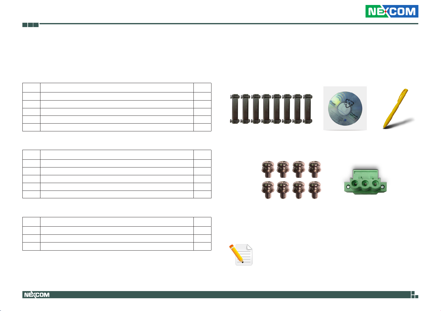
Package Contents
Before continuing, verify that the package you received is complete. Your package should have all the items listed in the table.
IPPC 1560T
Item Description Qty
1 Panel Mount Kit 8
2 Driver CD 1
3 Touch Pen 1
4 Flat Head for HDD Installation 8
5 *Terminal blocks 3-pin Phoenix Contact Plug 1
IPPC 1960T
Item Description Qty
1 Panel Mount Kit 8
2 Driver CD 1
3 Touch Pen 1
4 Flat Head for HDD Installation 8
5 *Terminal blocks 3-pin Phoenix Contact Plug 1
IPPC 2160P
Item Description Qty
1
Driver CD 1
2 Flat Head for HDD Installation 8
3 *Terminal blocks 3-pin Phoenix Contact Plug 1
* Terminal blocks 3-pin Phoenix Contact Plug is only for DC input model.
Copyright © 2014 NEXCOM International Co., Ltd. All Rights Reserved.
xv
Panel Mount Kit Driver CD Touch Pen
Flat Head for HDD Installation Terminal blocks
3-pin Phoenix
Contact Plug
Note: Package contents may vary depending on your country
region. Some items may be optional. Please contact your local
distributor for more information.
IPPC 1560T/1960T/2160P Series User Manual

Preface
Ordering Information
The following provides ordering information for the Industrial Panel PC series.
IPPC 1560T Series
• IPPC 1560TP2E-DC (P/N: 10II1560T00X0)
15” XGA LED backlight fanless touch panel PC, Intel
®
Core™ i5-3610ME
2.7GHz, touch screen, 4GB DDR3, 3 x COMs, DC power input
• IPPC 1560TP2E-AC (P/N: 10II1560T01X0)
15” XGA LED backlight fanless touch panel PC, Intel
®
Core™ i5-3610ME
2.7GHz, touch screen, 4GB DDR3, 6 x COMs, 4 x 4GPIO, 4 x 4DIO with
isolated protection, AC power input
• IPPC 1560TE (P/N: 10II1560T02X0)
15” XGA LED backlight fanless touch panel PC, Intel
®
Core™ i5-3610ME
2.7GHz, touch screen, 4GB DDR3, 3 x COMs, isolated protection DC Power
Optional
• 24V/5A, 120W AC to DC DIN rail power adapter w/ o power cord
(P/N: 7440120001X00) (for IPPC 1560TP2EDC and IPPC 1560TE)
• Riser card 2 x PCI slots (P/N: 20JK036P200X0)
• Riser card 2 x PCIe x4 slots (P/N: 20JK036E200X2)
• Fieldbus module universal kit (for IPPC 1560TP2E-DC and IPPC 1560TE)
88J50090E00X0 FBI 90E-PNM kit (w/ 25 cm cable) PROFINET master
88J50090E01X0 FBI 90E-EP kit (w/ 25 cm cable) EtherNet/IP master
88J50090E02X0 FBI 90E-ECM kit (w/ 25 cm cable) EtherCAT master
88J50090E03X0 FBI 90E-PBM kit (w/ 25 cm cable) PROFIBUS master
88J50090E04X0 FBI 90E-DNM kit (w/ 25 cm cable) DeviceNET master
IPPC 1960T Series
• IPPC 1960TP2E-DC (P/N: 10II1960T00X0)
19” SXGA LED backlight fanless touch panel PC, Intel
®
Core™ i5-3610ME
2.7GHz, touch screen, 4GB DDR3, 3 x COMs, DC power input
• IPPC 1960TP2E-AC (P/N: 10II1960T01X0)
19” SXGA LED backlight fanless touch panel PC, Intel® Core™ i5-3610ME
2.7GHz, touch screen, 4GB DDR3, 6 x COMs, 4 x 4GPIO, 4 x 4DIO with
isolated protection, AC power input
Optional
• 24V/5A, 120W AC to DC DIN rail power adapter w/ o power cord
(P/N: 7440120001X00) (for IPPC 1960TP2EDC only)
• Riser card 2 x PCI slots (P/N: 20JK036P200X0)
• Riser card 2 x PCIe x4 slots (P/N: 20JK036E200X2)
• Fieldbus module universal kit (for IPPC 1960TP2E-DC only)
88J50090E00X0 FBI 90E-PNM kit (w/ 25 cm cable) PROFINET master
88J50090E01X0 FBI 90E-EP kit (w/ 25 cm cable) EtherNet/IP master
88J50090E02X0 FBI 90E-ECM kit (w/ 25 cm cable) EtherCAT master
88J50090E03X0 FBI 90E-PBM kit (w/ 25 cm cable) PROFIBUS master
88J50090E04X0 FBI 90E-DNM kit (w/ 25 cm cable) DeviceNET master
Copyright © 2014 NEXCOM International Co., Ltd. All Rights Reserved.
xvi
IPPC 1560T/1960T/2160P Series User Manual

Preface
IPPC 2160P
• IPPC 2160PP2E-AC (P/N: 10II2160P00X0)
21.5” Full HD LED backlight fanless touch panel PC, Intel® Core™ i5-3610ME
2.7GHz, ten points P-Cap touch screen, 4GB DDR3, 6 x COMs, 4 x 4 GPIO, 4
x 4 DI/O with isolated protection, AC power input
Optional
• Riser card 2 x PCI slots (P/N: 20JK036P200X0)
• Riser card 2 x PCIe x4 slots (P/N: 20JK036E200X2)
Copyright © 2014 NEXCOM International Co., Ltd. All Rights Reserved.
xvii
IPPC 1560T/1960T/2160P Series User Manual
Chapter 1: Product Introduction
Chapter 1: Product Introduction
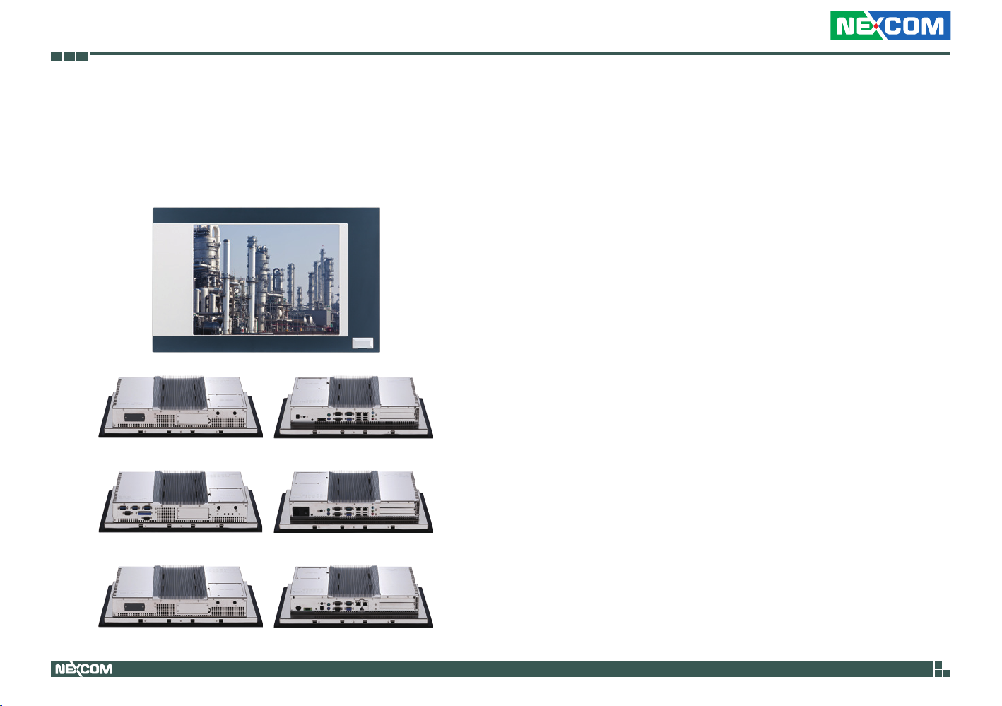
IPPC 1560T Series
IPPC 1560TP2E-DC
IPPC 1560TP2E-AC
Key Features
▪ 4:3 15” XGA Fanless Panel Computer
▪ Powerful 2nd/3rd generation Intel® Core™ processor
▪ Two expansion slots for add-on PCI or/and PCIe cards
▪ Optional 3.5G/Wi-Fi module/2.5” HDD/3 x Coms/GPIO/DIO/
▪ Dimming Control Button
▪ Front accessible USB2.0 for easy of field maintenance
▪ Metal housing with robust aluminum front bezel for harsh environment
▪ IP65 compliant front panel
▪ Support fieldbus module, JMobile HMI, Citect SCADA and CODESYS
▪ SoftLogic (optional)
▪ Optional: wide range DC power input model/isolation protection DC
▪ power input model
IPPC 1560TE
Copyright © 2014 NEXCOM International Co., Ltd. All Rights Reserved.
1
IPPC 1560T/1960T/2160P Series User Manual

Chapter 1: Product Introduction
Specifications
System
▪ CPU: Support 2nd/3rd gen. Intel® Core™ processor family, rPGA 988
®
– Intel
Core™ i7-3520ME (2 x 2.9GHz, 4M cache, Max. TDP 35W)
®
– Intel
Core™ i5-3610ME (2 x 2.7GHz, 3M cache, Max. TDP 35W)
(Default)
®
– Intel
Core™ i3-3120ME (2 x 2.4GHz, 3M cache, Max. TDP 35W)
®
– Intel
Celeron® B810 (2 x 1.6GHz, 2M cache, Max. TDP 35W)
®
– Intel
Pentium® B950 (2 x 2.1GHz, 2M cache, Max. TDP 35W)
▪ BIOS: AMI BIOS
▪ System chipset: Intel
®
HM76 Express chipset
▪ System memory: 1x 204-pin DDR3 SO-DIMM socket, 4G DDR3 (default),
support up to 8GB DDR3-1066/1333, non-ECC and un-buffered
▪ Storage Device:
– 1x external locked CFast socket
– 2x hard drive bay: optional 2x 2.5” SATA HDD
▪ Watchdog timer: Watchdog timeout can be programmed by software
from 1 second to 255 seconds and from 1 minute to 255 minutes
(Tolerance 15% under room temperature 25°C)
▪ H/W status monitor: Monitoring system temperature, and voltage
▪ Expansion:
– 2x Mini-PCIe sockets (support optional Wi-Fi or 3.5G module)
– 2x expansion slots for add-on PCI or/and PCIe cards
– 1x PCI and 1x PCIe x4 slots (default)
– 2x PCIe x4 slots
– 2x PCI slots
▪ Panel backlight control button: increase brightness/decrease brightness/
backlight on/off (for IPPC 1560TP2E-AC only)
Rear I/O
For All
▪ 2x PS2 keyboard/mouse
▪ 2nd display VGA port: 1x DB15
▪ Ethernet: 2x RJ45
For IPPC 1560TP2E-DC only
▪ USB: 5x USB2.0 (1 in front)
▪ Audio port: 1x Line-out; 1x Line-in; 1x MIC-in
▪ COM #1: RS232/422/485 w/ RI or 5V or 12V selection
▪ COM #2: RS232/422/485 w/ RI or 5V or 12V selection
▪ COM #3: RS232 w/ RI or 5V or 12V selection
▪ ATX power switch
▪ Reset button
For IPPC 1560TP2E-AC only
▪ USB: 5x USB2.0 (1 in front)
▪ Audio port: 1x Line-out; 1x Line-in; 1x MIC-in
▪ COM #1: RS232/422/485 w/ 2.5kv isolated protection
▪ COM #2: RS232/422/485 w/ 2.5kv isolated protection
▪ COM #3: RS232 w/ RI or 5V or 12V selection
▪ COM #4: RS232 w/ RI or 5V or 12V selection
▪ COM #5: RS232
▪ COM #6: RS232
▪ DIO w/ 2.5kv isolated protection:
– 4x Digital Input (source type)
– 4x Digital Output (sink type)
▪ GPIO: 4x digital in/4x digital out
▪ LPT: Parallel port
▪ AC Power switch
▪ Reset button
Copyright © 2014 NEXCOM International Co., Ltd. All Rights Reserved.
2
IPPC 1560T/1960T/2160P Series User Manual

Chapter 1: Product Introduction
For IPPC 1560TE only
▪ USB: 4x USB2.0 (Hidden)
▪ COM #1: RS232/422/485 w/ 2.5kv isolated protection
▪ COM #2: RS232/422/485 w/ 2.5kv isolated protection
▪ COM #3: RS232 w/ RI or 5V or 12V selection
▪ ATX Power switch
▪ Reset button
Audio
▪ AC97 codec: Realtek ALC886-GR
▪ Audio interface: Line-out/Line-in/MIC-in audio Jack
Ethernet
▪ LAN chip: dual Intel® 82574L Gigabit LAN
▪ Ethernet interface: 10/100/1000 Based-Tx Ethernet compatible
Fieldbus
▪ IPPC 1560TP2E-DC/IPPC 1560TE: support up to two fieldbus module (1
universal kit and 1 special kit)
▪ IPPC 1560TP2E-AC: support one special fieldbus module kit
Mechanical & Environment
▪ Color: pantone 432C\ RAL 70 24 front bezel
▪ Enclosure: aluminum front bezel with SPPC nickel plated housing
▪ IP protection: IP65 front
▪ Mounting: panel/wall/stand/VESA 100mm x 100mm
▪ Power
For IPPC 1560TP2E-DC
– Power Input: +9 to 30VDC
– Power Adapter: optional AC to DC DIN rail power adapter (+24V,
120W)
For IPPC 1560TP2E-AC
– Power input: 100-240V~, 1.5A, 50-60Hz; fuse: 250VAC/3A
– Power connector: AC inlet (IEC60320 C14)
– Power supply: 120W
For IPPC 1560TE
– Power input: +24V DC+-20% with 1.5kv isolated protection
– Fuse: 250V/10A
▪ Vibration:
– IEC 68 2-64 (w/ HDD)
– 1Grms @ sine, 5~500Hz, 1hr/axis (HDD operating)
– 2Grms @ sine, 5~500Hz, 1hr/axis (CFast operating)
– 2.2Grms @ random condition, 5~500Hz, 0.5hr/axis (non-operating)
▪ Shock:
– IEC 68 2-27
– HDD: 20G @ wall mount, half sine, 11ms
▪ Operating temperature: -10°C to 50°C
* Intel® Core™ i7/Intel® Celeron® B810/Intel® Pentium® B950: -10°C to 40°C
▪ Storage temperature: -20°C to 75°C
▪ Operating humidity: 10%~90% relative humidity, non-condensing
Limits to be at 90% RH at max 50°C
Certifications
▪ CE (including EN61000-6-2/EN61000-6-4)
▪ FCC Class A
Copyright © 2014 NEXCOM International Co., Ltd. All Rights Reserved.
3
IPPC 1560T/1960T/2160P Series User Manual
Chapter 1: Product Introduction
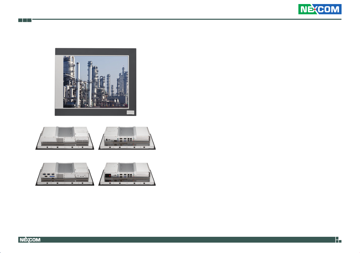
IPPC 1960T Series
IPPC 1960TP2E-DC
Key Features
▪ 4:3 19” SXGA Fanless Panel Computer
®
▪ Powerful 2nd/3rd generation Intel
Core™ processor
▪ Two expansion slots for add-on PCI or/and PCIe cards
▪ Optional 3.5G/Wi-Fi module/2.5” HDD/3x Coms/GPIO/DIO/Dimming
Control Button
▪ Front accessible USB2.0 for easy of field maintenance
▪ Metal housing with robust aluminum front bezel for harsh environment
▪ IP66 compliant front panel
▪ Support fieldbus module, JMobile HMI, Citect SCADA and CODESYS
SoftLogic (optional)
▪ Wide range DC power input model
IPPC 1960TP2E-AC
Copyright © 2014 NEXCOM International Co., Ltd. All Rights Reserved.
4
IPPC 1560T/1960T/2160P Series User Manual

Chapter 1: Product Introduction
Specifications
System
▪ CPU: Support 2nd/3rd gen. Intel® Core™ processor family, rPGA 988
®
– Intel
Core™ i7-3520ME (2 x 2.9GHz, 4M cache, Max. TDP 35W)
®
– Intel
Core™ i5-3610ME (2 x 2.7GHz, 3M cache, Max. TDP 35W)
(Default)
®
– Intel
Core™ i3-3120ME (2 x 2.4GHz, 3M cache, Max. TDP 35W)
®
– Intel
Celeron® B810 (2 x 1.6GHz, 2M cache, Max. TDP 35W)
®
– Intel
Pentium® B950 (2 x 2.1GHz, 2M cache, Max. TDP 35W)
▪ BIOS: AMI BIOS
▪ System chipset: Intel
®
HM76 Express chipset
▪ System memory: 1x 204-pin DDR3 SO-DIMM socket, 4G DDR3 (default),
support up to 8GB DDR3-1066/1333, non-ECC and un-buffered
▪ Storage Device:
– 1x external locked CFast socket
– 2x hard drive bay: optional 2x 2.5” SATA HDD
▪ Watchdog timer: Watchdog timeout can be programmed by software
from 1 second to 255 seconds and from 1 minute to 255 minutes
(Tolerance 15% under room temperature 25°C)
▪ H/W status monitor: Monitoring system temperature, and voltage
▪ Expansion:
– 2x Mini-PCIe sockets (support optional Wi-Fi or 3.5G module)
– 2x expansion slots for add-on PCI or/and PCIe cards
– 1x PCI and 1x PCIe x4 slots (default)
– 2x PCIe x4 slots
– 2x PCI slots
▪ Panel backlight control button: increase brightness/decrease brightness/
backlight on/off (for IPPC 1960TP2E-AC only)
Rear I/O
For All
▪ 2x PS2 keyboard/mouse
▪ 2nd display VGA port: 1x DB15
▪ Ethernet: 2x RJ45
▪ USB: 5x USB2.0 (1 in front)
▪ Audio port: 1x Line-out; 1x Line-in; 1x MIC-in
For IPPC 1960TP2E-DC only
▪ COM #1: RS232/422/485 w/ RI or 5V or 12V selection
▪ COM #2: RS232/422/485 w/ RI or 5V or 12V selection
▪ COM #3: RS232 w/ RI or 5V or 12V selection
▪ ATX power switch
▪ Reset button
For IPPC 1960TP2E-AC only
▪ COM #1: RS232/422/485 w/ 2.5kv isolated protection
▪ COM #2: RS232/422/485 w/ 2.5kv isolated protection
▪ COM #3: RS232 w/ RI or 5V or 12V selection
▪ COM #4: RS232 w/ RI or 5V or 12V selection
▪ COM #5: RS232
▪ COM #6: RS232
▪ DIO w/ 2.5kv isolated protection:
– 4x Digital Input (source type)
– 4x Digital Output (sink type)
▪ GPIO: 4x digital in/4x digital out
▪ LPT: Parallel port
▪ AC Power switch
▪ Reset button
Copyright © 2014 NEXCOM International Co., Ltd. All Rights Reserved.
5
IPPC 1560T/1960T/2160P Series User Manual

Chapter 1: Product Introduction
Audio
▪ AC97 codec: Realtek ALC886-GR
▪ Audio interface: Line-out/Line-in/MIC-in audio Jack
Ethernet
▪ LAN chip: dual Intel® 82574L Gigabit LAN
▪ Ethernet interface: 10/100/1000 Based-Tx Ethernet compatible
Fieldbus
▪ IPPC 1960TP2E-DC: support up to two Fieldbus Module (1 universal kit
and 1 special kit)
▪ IPPC 1960TP2E-AC: support one special Fieldbus Module kit
Mechanical & Environment
▪ Color: pantone 432C\ RAL 70 24 front bezel
▪ Enclosure: aluminum front bezel with SPPC nickel plated housing
▪ IP protection: IP65 front
▪ Mounting: panel/wall/stand/VESA 100mm x 100mm
▪ Power
For IPPC 1960TP2E-DC
– Power input: +9 to 30VDC
– Power adapter: optional AC to DC DIN rail power adapter (+24V,
120W)
For IPPC 1960TP2E-AC
– Power input: 100-240V~, 1.5A, 50-60Hz; Fuse: 250VAC/3A
– Power connector: AC inlet (IEC60320 C14)
– Power supply: 120W
▪ Vibration:
– IEC 68 2-64 (w/ HDD)
– 1Grms @ sine, 5~500Hz, 1hr/axis (HDD operating)
– 2Grms @ sine, 5~500Hz, 1hr/axis (CFast operating)
– 2.2Grms @ random condition, 5~500Hz, 0.5hr/axis (non-operating)
▪ Shock:
– IEC 68 2-27
– HDD: 20G @ wall mount, half sine, 11ms
▪ Operating temperature: -10°C to 50°C
* Intel® Core™ i7/Intel® Celeron® B810/Intel® Pentium® B950: -10°C to 40°C
▪ Storage temperature: -20°C to 75°C
▪ Operating humidity: 10%~90% relative humidity, non-condensing
Limits to be at 90% RH at max 50°C
Certifications
▪ CE (including EN61000-6-2/EN61000-6-4)
▪ FCC Class A
Copyright © 2014 NEXCOM International Co., Ltd. All Rights Reserved.
6
IPPC 1560T/1960T/2160P Series User Manual

Chapter 1: Product Introduction
IPPC 2160P
Key Features
▪ 16:9 21.5” Full HD fanless LED panel computer
®
▪ Powerful 2nd/3rd generation Intel
Core™ processor
▪ Two expansion slots for add-on PCI or/and PCIe cards
▪ Optional 3.5G/Wi-Fi module/2.5” HDD/3x Coms/GPIO/DIO/Dimming
control button
▪ 10 points P-Cap multi-touch with zero bezel flush front design
▪ Metal housing with robust aluminum front bezel for harsh environment
▪ IP66 compliant front panel
▪ Anti-scratch surface: 7H hardness
▪ Support fieldbus module, JMobile HMI, Citect SCADA and CODESYS
SoftLogic (optional)
Copyright © 2014 NEXCOM International Co., Ltd. All Rights Reserved.
▪ Optional: AC power input model/DC power input model
7
IPPC 1560T/1960T/2160P Series User Manual

Chapter 1: Product Introduction
Specifications
Panel
▪ LED size: 21.5”, 16:9
▪ Resolution: Full HD 1920 x 1080
▪ Luminance: 300cd/m
2
▪ Contrast ratio: 5000
▪ LCD color: 16.7M
▪ Viewing angle: 89(U), 89(D), 89(L), 89(R)
▪ Backlight: LED
Touch Screen
▪ Ten points P-Cap (Projected Capacitive Touch)
▪ Touch light transmission: 87%
▪ Anti-scratch surface: 7H hardness
▪ Touch interface: USB
▪ Windows 8 compliance
System
▪ CPU: Support 2nd/3rd gen. Intel® Core™ processor family, rPGA 988
®
– Intel
Core™ i7-3520ME (2 x 2.9GHz, 4M cache, Max. TDP 35W)
®
– Intel
Core™ i5-3610ME (2 x 2.7GHz, 3M cache, Max. TDP 35W)
(Default)
®
– Intel
Core™ i3-3120ME (2 x 2.4GHz, 3M cache, Max. TDP 35W)
®
– Intel
Celeron® B810 (2 x 1.6GHz, 2M cache, Max. TDP 35W)
®
– Intel
Pentium® B950 (2 x 2.1GHz, 2M cache, Max. TDP 35W)
▪ BIOS: AMI BIOS
▪ System chipset: Intel
®
HM76 Express chipset
▪ System memory: 1x 204-pin DDR3 SO-DIMM socket, 4G DDR3 (default),
support up to 8GB DDR3-1066/1333, non-ECC and un-buffered
▪ Storage Device:
– 1x external locked CFast socket
– 2x hard drive bay: optional 2x 2.5” SATA HDD
▪ Watchdog timer: Watchdog timeout can be programmed by software
from 1 second to 255 seconds and from 1 minute to 255 minutes
(Tolerance 15% under room temperature 25°C)
▪ H/W status monitor: Monitoring system temperature, and voltage
▪ Expansion:
– 2x Mini-PCIe sockets (support optional Wi-Fi or 3.5G module)
– 2x expansion slots for add-on PCI or/and PCIe cards
– 1x PCI and 1x PCIe x4 slots (default)
– 2x PCIe x4 slots
– 2x PCI slots
▪ Panel backlight control button: increase brightness/decrease brightness/
backlight on/off
Rear I/O
▪ Ethernet: 2x RJ45
▪ 2nd display VGA port: 1x DB15
▪ Audio port: 1x Line-out; 1x Line-in; 1x MIC-in
▪ USB: 4x USB 2.0
▪ 2x PS2 keyboard/mouse
▪ AC power switch
▪ Reset button
▪ DIO w/ 2.5kv isolated protection:
4x digital input (source type)
– Input voltage (dry contact): Logic 0: Close to GND
Logic 1: open
– Input voltage: Logic 0: 3V max.
Logic 1: +5 to 30V
Copyright © 2014 NEXCOM International Co., Ltd. All Rights Reserved.
8
IPPC 1560T/1960T/2160P Series User Manual

Chapter 1: Product Introduction
4x digital outp3ut (Sink type)
– Output voltage: +3.6 to 5V
– Sink current: 200mA max. per channel
▪ GPIO: 4x digital in/4x digital out
▪ COM #1: RS232/422/485 w/ 2.5kv isolated protection
▪ COM #2: RS232/422/485 w/ 2.5kv isolated protection
▪ COM #3: RS232 w/ RI or 5V or 12V selection
▪ COM #4: RS232 w/ RI or 5V or 12V selection
▪ COM #5: RS232
▪ COM #6: RS232
▪ LPT: 1x parallel port
Audio
▪ AC97 codec: Realtek ALC886-GR
▪ Audio interface: Line-out/Line-in/MIC-in audio Jack
Ethernet
▪ LAN chip: dual Intel® 82574L Gigabit LAN
▪ Ethernet interface: 10/100/1000 Based-Tx Ethernet compatible
Fieldbus
▪ Support one special fieldbus module kit
Mechanical & Environment
▪ Color: pantone 432C\ RAL 70 24 front bezel
▪ Enclosure: aluminum front bezel with SPPC nickel plated housing
▪ IP protection: IP66 front
▪ Mounting: panel/wall/stand/VESA 100mm x 100mm
▪ System with panel mounting kit w/ o Panel mounting hole
▪ Power input: 100-240V~,1.5A,50-60Hz; Fuse: 250VAC/3A
Power connector: AC inlet (IEC60320 C14)
Power supply: 120W
▪ Vibration:
– IEC 68 2-64 (w/ HDD)
– 1Grms @ sine, 5~500Hz, 1hr/axis (HDD operating)
– 2Grms @ sine, 5~500Hz, 1hr/axis (CFast operating)
– 2.2Grms @ random condition, 5~500Hz, 0.5hr/axis (non-operating)
▪ Shock:
– IEC 68 2-27
– HDD: 20G @ wall mount, half sine, 11ms
▪ Operating temperature: -10°C to 50°C
* Intel® Core™ i7/Intel® Celeron® B810/Intel® Pentium® B950: -10°C to 40°C
▪ Storage temperature: -20°C to 75°C
▪ Operating humidity: 10%~90% relative humidity, non-condensing
▪ Dimension: 562.4mm x 382.4mm x 92.27mm
▪ Weight: 12.51Kg
Certifications
▪ CE (including EN61000-6-1/EN61000-6-2/EN61000-6-3/EN61000-6-4)
▪ FCC Class B
Copyright © 2014 NEXCOM International Co., Ltd. All Rights Reserved.
9
IPPC 1560T/1960T/2160P Series User Manual
Chapter 1: Product Introduction
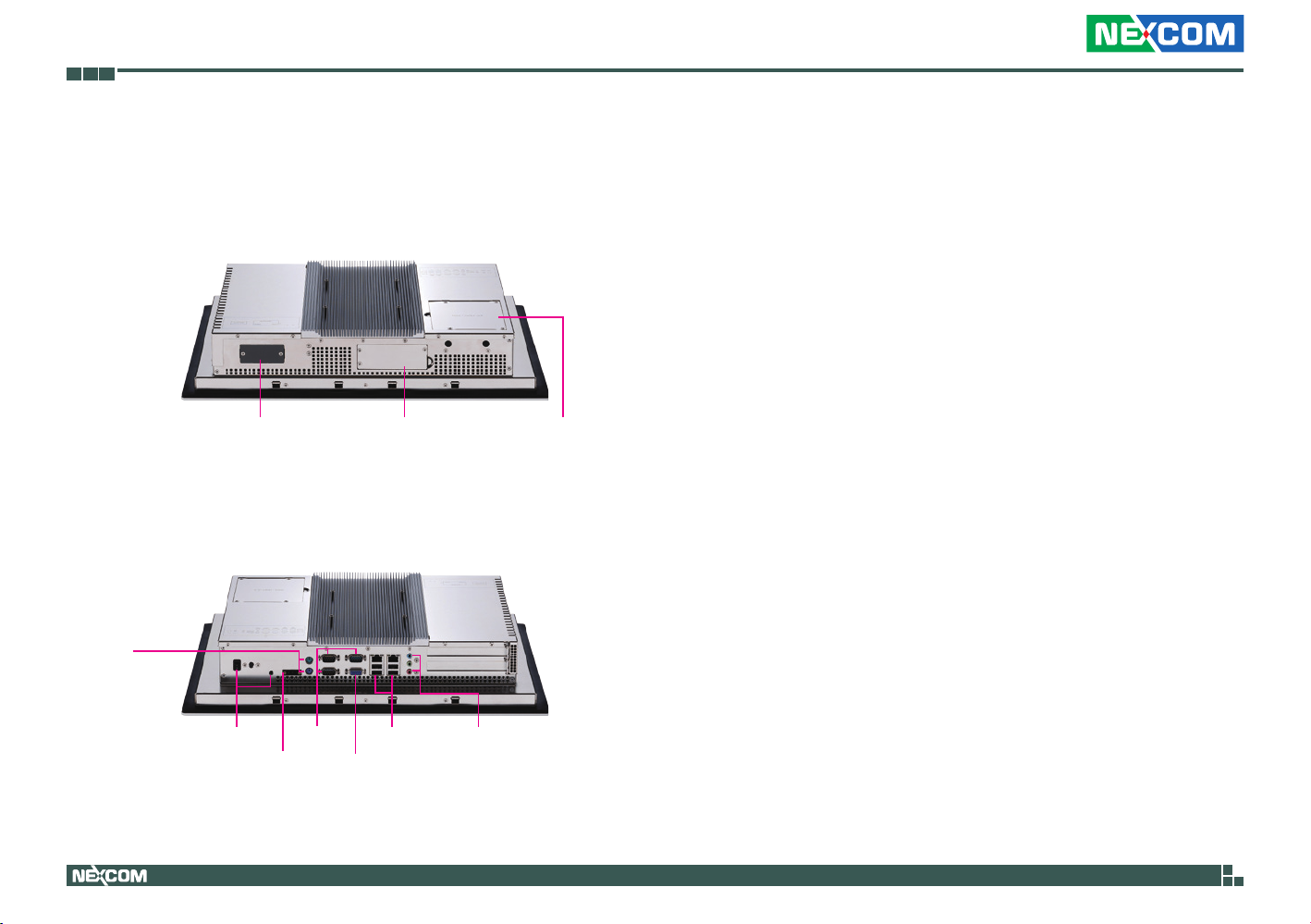
Knowing Your IPPC 1560T Series
IPPC 1560TP2E-DC Rear Top
Fieldbus (Universal Kit) Fieldbus (Special Kit) 2.5” HDD/SDD
IPPC 1560TP2E-DC Rear Bottom
PS/2
KB/MS
Drive Bay
Fieldbus (Universal Kit and Special Kit)
Expansion slots for add-on fieldbus modules.
2.5” HDD/SDD Drive Bay
Used to install a 2.5” HDD/SSD.
Power Switch
Press to power-on or power-off the system.
Reset Switch
Press this button to restart the system.
DC Input
Used to plug a DC power cord.
PS/2 KB/MS
Used to connect a PS/2 keyboard and a PS/2 mouse.
COM 1 to COM 3
COM 1 and COM 2 ports have 2.5kV isolated protection and support
RS232/422/485 compatible serial devices.
COM 3 supports RS232 and 5V, 12V or RI by selection.
VGA
Used to connect an analog VGA monitor.
LAN
Used to connect the system to a local area network. LAN1 supports Wake
up on LAN.
Power &
Reset Switch
Copyright © 2014 NEXCOM International Co., Ltd. All Rights Reserved.
COM1~3
DC Input VGA
LAN & USB Audio Connectors
USB
Used to connect USB 2.0/1.1 devices.
Audio Connectors
Line-in, mic-in and line-out ports used to connect audio devices such as
external microphones, speakers and headphones.
10
IPPC 1560T/1960T/2160P Series User Manual

Chapter 1: Product Introduction
COM4
COM5
COM6
PS/2
KB/MS
AC
Input
IPPC 1560TP2E-AC Rear Top
GPIO
Fieldbus (Special Kit)DIO
LPT
IPPC 1560TP2E-AC Rear Bottom
Power &
Reset Switch
COM1~3
LAN & USB Audio Connectors
VGA
2.5 HDD
Drive Bay
COM 4 to COM 6
These COM ports support RS232 compatible serial devices.
COM 4 supports
5V, 12V or RI by selection.
GPIO
The GPIO connector supports 4 digital input and 4 digital output.
DIO
The GPIO connector supports 4 digital input and 4 digital output with
2.5kV isolated protection.
LPT
Parallel port used to connect LPT devices.
Fieldbus (Special Kit)
Expansion slot for add-on fieldbus modules.
2.5” HDD/SDD Drive Bay
Used to install a 2.5” HDD/SSD.
Power Switch
Press to power-on or power-off the system.
Reset Switch
Press this button to restart the system.
AC Input
Used to plug an AC power cord.
Copyright © 2014 NEXCOM International Co., Ltd. All Rights Reserved.
PS/2 KB/MS
Used to connect a PS/2 keyboard and a PS/2 mouse.
11
IPPC 1560T/1960T/2160P Series User Manual

Chapter 1: Product Introduction
COM 1 to COM 3
COM 1 and COM 2 ports have 2.5kV isolated protection and support
RS232/422/485 compatible serial devices.
COM 3 supports RS232 and 5V, 12V or RI by selection.
VGA
Used to connect an analog VGA monitor.
LAN
Used to connect the system to a local area network. LAN1 supports Wake
up on LAN.
USB
Used to connect USB 2.0/1.1 devices.
Audio Connectors
Line-in, mic-in and line-out ports used to connect audio devices such as
external microphones, speakers and headphones.
Copyright © 2014 NEXCOM International Co., Ltd. All Rights Reserved.
12
IPPC 1560T/1960T/2160P Series User Manual

Chapter 1: Product Introduction
IPPC 1560TE Rear Top
Fieldbus (Universal Kit) Fieldbus (Special Kit) 2.5 HDD
IPPC 1560TE Rear Bottom
PS/2
KB/MS
Power Switch
DC Input VGA
COM1~3
LAN Audio Connectors
Drive Bay
Fieldbus (Universal Kit and Special Kit)
Expansion slots for add-on fieldbus modules.
2.5” HDD/SDD Drive Bay
Used to install a 2.5” HDD/SSD.
Power Switch
Press to power-on or power-off the system.
Reset Switch
Press this button to restart the system.
DC Input
Used to plug a DC power cord.
PS/2 KB/MS
Used to connect a PS/2 keyboard and a PS/2 mouse.
COM 1 to COM 3
COM 1 and COM 2 ports have 2.5kV isolated protection and support
RS232/422/485 compatible serial devices.
COM 3 supports RS232 and 5V, 12V or RI by selection.
VGA
Used to connect an analog VGA monitor.
LAN
Used to connect the system to a local area network. LAN1 supports Wake
up on LAN.
Copyright © 2014 NEXCOM International Co., Ltd. All Rights Reserved.
Audio Connectors
Line-in, mic-in and line-out ports used to connect audio devices such as
external microphones, speakers and headphones.
13
IPPC 1560T/1960T/2160P Series User Manual

Chapter 1: Product Introduction
Knowing Your IPPC 1960T Series
IPPC 1960TP2E-DC Rear Top
Fieldbus (Universal Kit) Fieldbus (Special Kit) 2.5” HDD/SDD
IPPC 1960TP2E-DC Rear Bottom
PS/2
KB/MS
Drive Bay
Fieldbus (Universal Kit and Special Kit)
Expansion slots for add-on fieldbus modules.
2.5” HDD/SDD Drive Bay
Used to install a 2.5” HDD/SSD.
Power Switch
Press to power-on or power-off the system.
Reset Switch
Press this button to restart the system.
DC Input
Used to plug a DC power cord.
PS/2 KB/MS
Used to connect a PS/2 keyboard and a PS/2 mouse
COM 1 to COM 3
COM 1 and COM 2 ports have 2.5kV isolated protection and support
RS232/422/485 compatible serial devices.
COM 3 supports RS232 and 5V, 12V or RI by selection.
VGA
Used to connect an analog VGA monitor.
LAN
Used to connect the system to a local area network. LAN1 supports Wake
up on LAN.
Power &
Reset Switch
Copyright © 2014 NEXCOM International Co., Ltd. All Rights Reserved.
COM1~3
DC Input VGA
LAN & USB Audio Connectors
USB
Used to connect USB 2.0/1.1 devices.
Audio Connectors
Line-in, mic-in and line-out ports used to connect audio devices such as
external microphones, speakers and headphones.
14
IPPC 1560T/1960T/2160P Series User Manual

Chapter 1: Product Introduction
COM4
COM5
COM6
PS/2
KB/MS
AC
Input
IPPC 1960TP2E-AC Rear Top
GPIO
Fieldbus (Special Kit)DIO
LPT
IPPC 1960TP2E-AC Rear Bottom
2.5 HDD
Drive Bay
COM 4 to COM 6
These COM ports support RS232 compatible serial devices.
COM 4 supports
5V, 12V or RI by selection.
GPIO
The GPIO connector supports 4 digital input and 4 digital output.
DIO
The GPIO connector supports 4 digital input and 4 digital output with
2.5kV isolated protection.
LPT
Parallel port used to connect LPT devices.
Fieldbus (Special Kit)
Expansion slot for add-on fieldbus modules.
2.5” HDD/SDD Drive Bay
Used to install a 2.5” HDD/SSD.
Power Switch
Press to power-on or power-off the system.
Reset Switch
Press this button to restart the system.
Power &
Reset Switch
Copyright © 2014 NEXCOM International Co., Ltd. All Rights Reserved.
COM1~3
VGA
LAN & USB Audio Connectors
AC Input
Used to plug an AC power cord.
PS/2 KB/MS
Used to connect a PS/2 keyboard and a PS/2 mouse.
15
IPPC 1560T/1960T/2160P Series User Manual

Chapter 1: Product Introduction
COM 1 to COM 3
COM 1 and COM 2 ports have 2.5kV isolated protection and support
RS232/422/485 compatible serial devices.
COM 3 supports RS232 and 5V, 12V or RI by selection.
VGA
Used to connect an analog VGA monitor.
LAN
Used to connect the system to a local area network. LAN1 supports Wake
up on LAN.
USB
Used to connect USB 2.0/1.1 devices.
Audio Connectors
Line-in, mic-in and line-out ports used to connect audio devices such as
external microphones, speakers and headphones.
Copyright © 2014 NEXCOM International Co., Ltd. All Rights Reserved.
16
IPPC 1560T/1960T/2160P Series User Manual

Chapter 1: Product Introduction
Knowing Your IPPC 2160P
IPPC 2160P Rear Top
COM4
COM5
COM6
GPIO
IPPC 2160P Rear Bottom
PS/2
KB/MS
AC
Input
Fieldbus (Special Kit)DIO
LPT
2.5 HDD
Drive Bay
COM 4 to COM 6
These COM ports support RS232 compatible serial devices.
COM 4 supports
5V, 12V or RI by selection.
GPIO
The GPIO connector supports 4 digital input and 4 digital output.
DIO
The GPIO connector supports 4 digital input and 4 digital output with
2.5kV isolated protection.
LPT
Parallel port used to connect LPT devices.
Fieldbus (Special Kit)
Expansion slot for add-on fieldbus modules.
2.5” HDD/SDD Drive Bay
Used to install a 2.5” HDD/SSD.
Power Switch
Press to power-on or power-off the system.
Reset Switch
Press this button to restart the system.
AC Input
Used to plug an AC power cord.
Power &
Reset Switch
Copyright © 2014 NEXCOM International Co., Ltd. All Rights Reserved.
COM1~3
VGA
LAN & USB Audio Connectors
PS/2 KB/MS
Used to connect a PS/2 keyboard and a PS/2 mouse.
17
IPPC 1560T/1960T/2160P Series User Manual

Chapter 1: Product Introduction
COM 1 to COM 3
COM 1 and COM 2 ports have 2.5kV isolated protection and support
RS232/422/485 compatible serial devices.
COM 3 supports RS232 and 5V, 12V or RI by selection.
VGA
Used to connect an analog VGA monitor.
LAN
Used to connect the system to a local area network. LAN1 supports Wake
up on LAN.
USB
Used to connect USB 2.0/1.1 devices.
Audio Connectors
Line-in, mic-in and line-out ports used to connect audio devices such as
external microphones, speakers and headphones.
Copyright © 2014 NEXCOM International Co., Ltd. All Rights Reserved.
18
IPPC 1560T/1960T/2160P Series User Manual

Chapter 1: Product Introduction
IPPC 1560T Series Rear
VESA Mounting Hole
VESA Mounting Hole
VESA Mounting Hole
VESA Mounting Hole
VESA Mounting Holes
These are mounting holes for VESA mount (100x100mm)
Copyright © 2014 NEXCOM International Co., Ltd. All Rights Reserved.
19
IPPC 1560T/1960T/2160P Series User Manual

Chapter 1: Product Introduction
IPPC 1960T Series Rear
VESA Mounting Hole
VESA Mounting Hole
VESA Mounting Hole
VESA Mounting Hole
VESA Mounting Holes
These are mounting holes for VESA mount (100x100mm)
Copyright © 2014 NEXCOM International Co., Ltd. All Rights Reserved.
20
IPPC 1560T/1960T/2160P Series User Manual

Chapter 1: Product Introduction
IPPC 2160P Rear
VESA Mounting Hole
VESA Mounting Hole
VESA Mounting Hole
VESA Mounting Hole
VESA Mounting Holes
These are mounting holes for VESA mount (100x100mm)
Copyright © 2014 NEXCOM International Co., Ltd. All Rights Reserved.
21
IPPC 1560T/1960T/2160P Series User Manual

Chapter 1: Product Introduction
Mechanical Dimensions
IPPC 1560TP2E-DC
477.64 (OUTLINE)
84.72
38.95
310 (OUTLINE)
232.1 (BEZEL OPENING)
Copyright © 2014 NEXCOM International Co., Ltd. All Rights Reserved.
308.2 (BEZEL OPENING)
Active Area (304.1x228.1)
Active Center
22
95.72
6
29.3
10
100 186.02
92.75100
A
290 (MOUNTING LINE)
450 (MOUNTING LINE) 13.82
IPPC 1560T/1960T/2160P Series User Manual

Chapter 1: Product Introduction
IPPC 1560TP2E-AC
477.64 (OUTLINE)
84.72
308.2 (BEZEL OPENING)
38.95
Active Area (304.1x228.1)
310 (OUTLINE)
232.1 (BEZEL OPENING)
Copyright © 2014 NEXCOM International Co., Ltd. All Rights Reserved.
Active Center
23
95.72
6
29.3
10
100 186.02
92.75100
A
290 (MOUNTING LINE)
450 (MOUNTING LINE) 13.82
IPPC 1560T/1960T/2160P Series User Manual

Chapter 1: Product Introduction
IPPC 1560TE
477.64 (OUTLINE)
84.72
308.2 (BEZEL OPENING)
38.95
Active Area (304.1x228.1)
310 (OUTLINE)
232.1 (BEZEL OPENING)
Copyright © 2014 NEXCOM International Co., Ltd. All Rights Reserved.
24
95.72
6
29.3
10
100 186.02
92.75100
A
290 (MOUNTING LINE)
450 (MOUNTING LINE) 13.82
IPPC 1560T/1960T/2160P Series User Manual

Chapter 1: Product Introduction
IPPC 1960TP2E-DC
450.00
398.42
477.64
99.38
33.36
6.00
Copyright © 2014 NEXCOM International Co., Ltd. All Rights Reserved.
25
399.24
269.60
380.00
IPPC 1560T/1960T/2160P Series User Manual

Chapter 1: Product Introduction
IPPC 1960TP2E-AC
450.00
398.42
477.64
99.38
33.36
6.00
Copyright © 2014 NEXCOM International Co., Ltd. All Rights Reserved.
26
399.24
269.60
380.00
IPPC 1560T/1960T/2160P Series User Manual

Chapter 1: Product Introduction
IPPC 2160P
562.40
Copyright © 2014 NEXCOM International Co., Ltd. All Rights Reserved.
382.40
6.70
92.27
19.15
27
542.00
362.00
IPPC 1560T/1960T/2160P Series User Manual

Chapter 2: Jumpers and Connectors
Chapter 2: Jumpers and Connectors
This chapter describes how to set the jumpers and connectors on the
motherboard in the IPPC 1560T/1960T/2160P series.
Before You Begin
▪ Ensure you have a stable, clean working environment. Dust and dirt can
get into components and cause a malfunction. Use containers to keep
small components separated.
▪ Adequate lighting and proper tools can prevent you from accidentally
damaging the internal components. Most of the procedures that follow
require only a few simple tools, including the following:
– A Philips screwdriver
– A flat-tipped screwdriver
– A set of jewelers screwdrivers
– A grounding strap
– An anti-static pad
▪ Using your fingers can disconnect most of the connections. It is
recommended that you do not use needle-nosed pliers to disconnect
connections as these can damage the soft metal or plastic parts of the
connectors.
▪ Before working on internal components, make sure that the power is off.
Ground yourself before touching any internal components, by touching
a metal object. Static electricity can damage many of the electronic
components. Humid environments tend to have less static electricity than
dry environments. A grounding strap is warranted whenever danger of
static electricity exists.
Precautions
Computer components and electronic circuit boards can be damaged by
discharges of static electricity. Working on computers that are still connected
to a power supply can be extremely dangerous.
Follow the guidelines below to avoid damage to your computer or yourself:
▪ Always disconnect the unit from the power outlet whenever you are
working inside the case.
▪ If possible, wear a grounded wrist strap when you are working inside the
computer case. Alternatively, discharge any static electricity by touching
the bare metal chassis of the unit case, or the bare metal body of any
other grounded appliance.
▪ Hold electronic circuit boards by the edges only. Do not touch the
components on the board unless it is necessary to do so. Don’t flex or
stress the circuit board.
▪ Leave all components inside the static-proof packaging that they shipped
with until they are ready for installation.
▪ Use correct screws and do not over tighten screws.
Copyright © 2014 NEXCOM International Co., Ltd. All Rights Reserved.
28
IPPC 1560T/1960T/2160P Series User Manual

Chapter 2: Jumpers and Connectors
Jumper Settings
A jumper is the simplest kind of electric switch. It consists of two metal
pins and a cap. When setting the jumpers, ensure that the jumper caps are
placed on the correct pins. When the jumper cap is placed on both pins, the
jumper is short. If you remove the jumper cap, or place the jumper cap on
just one pin, the jumper is open.
Refer to the illustrations below for examples of what the 2-pin and 3-pin
jumpers look like when they are short (on) and open (off).
Two-Pin Jumpers: Open (Left) and Short (Right)
Three-Pin Jumpers: Pins 1 and 2 are Short
3
2
1
Copyright © 2014 NEXCOM International Co., Ltd. All Rights Reserved.
1
3
2
29
IPPC 1560T/1960T/2160P Series User Manual

Chapter 2: Jumpers and Connectors
J6
J4
CN1
JP1
J1
J5
JP2
J2
Locations of the Jumpers and Connectors
CN2
KM1
CN6
CN7
U42
JP7
JP9
CON1
CON2
JP8
JP11
SLOT1
CN13
PWR1
JDB1
J13
J8
JP13
CN16
JP5
J7
CN15
J3
CN4
J9
J10
CN12
CN14
SW5
JP15
CN3
JP6
J11
JP3
SW6
CN17
CN8
SW1
CN19
JP4
CN5
JP10
CN10
CN11
CN18
Copyright © 2014 NEXCOM International Co., Ltd. All Rights Reserved.
30
IPPC 1560T/1960T/2160P Series User Manual

Chapter 2: Jumpers and Connectors
Jumpers and DIP Switch Settings
AT/ATX Power Type Select
Connector type: 1x3 3-pin header, 2.54mm pitch
Connector location: JP5
1 3 1 3
Pin Settings
1-2 On AT
2-3 On ATX
Pin Definition
1 ATMODE
2 MODE_SEL
3 ATXMODE
LCD Power Select
Connector type: 1x3 3-pin header, 2.54mm pitch
Connector location: JP2
Pin Settings
1-2 On VCC3
2-3 On VCC5
1-2 On: default
Pin Definition
1 VCC3
2 VCCLCDIN
3 VCC5
Copyright © 2014 NEXCOM International Co., Ltd. All Rights Reserved.
31
IPPC 1560T/1960T/2160P Series User Manual

Chapter 2: Jumpers and Connectors
CCFL Power Select
Connector type: 1x3 3-pin header, 2.54mm pitch
Connector location: JP3
1 3 1 3
Pin Settings
1-2 On VCC3
2-3 On VCC5
1-2 On: default
Pin Definition
1 VCC3
2 P_BKLTCTRL3
3 VCC5
Touch Panel Type Select
Connector type: 1x3 3-pin header, 2.54mm pitch
Connector location: JP4
Pin Settings
1-2 On 5 Wire
2-3 On 4 Wire
1-2 On: default
Pin Definition
1 NC
2 TOUCH_YU
3 SENSE
Copyright © 2014 NEXCOM International Co., Ltd. All Rights Reserved.
32
IPPC 1560T/1960T/2160P Series User Manual

Chapter 2: Jumpers and Connectors
15
26
CMOS Clear Select
Connector type: 1x3 3-pin header, 2.54mm pitch
Connector location: JP10
1 3
Pin Settings
1-2 On Normal
2-3 On Clear CMOS
1-2 On: default
Pin Definition
1 3VSB
2 VBAT
3 GND
RI Feature Selection (COM1)
Connector type: 2x3 6-pin header, 2.0mm pitch
Connector location: JP7
Pin Settings
1-2 On RI (Default)
3-4 On VCC5
5-6 On +12V
1-2 On: default
Pin Definition Pin Definition
1 SP1_PSRI# 2 SP1_RI#
3 SP1_PSRI# 4 ISO_VCC5
5 SP1_PSRI# 6 ISO_+12V
Copyright © 2014 NEXCOM International Co., Ltd. All Rights Reserved.
33
IPPC 1560T/1960T/2160P Series User Manual

Chapter 2: Jumpers and Connectors
15
26
15
26
RI Feature Selection (COM2)
Connector type: 2x3 6-pin header, 2.0mm pitch
Connector location: JP8
Pin Settings
1-2 On RI (Default)
3-4 On VCC5
5-6 On +12V
1-2 On: default
Pin Definition Pin Definition
1 SP2_PSRI# 2 SP2_RI#
3 SP2_PSRI# 4 ISO_VCC5_A
5 SP2_PSRI# 6 ISO_+12V
RI Feature Selection (COM3)
Connector type: 2x3 6-pin header, 2.0mm pitch
Connector location: JP9
Pin Settings
1-2 On RI (Default)
3-4 On VCC5
5-6 On +12V
1-2 On: default
Pin Definition Pin Definition
1 SP3_PSRI# 2 SP3_RI#
3 SP3_PSRI# 4 ISO_VCC5
5 SP3_PSRI# 6 ISO_+12V
Copyright © 2014 NEXCOM International Co., Ltd. All Rights Reserved.
34
IPPC 1560T/1960T/2160P Series User Manual

Chapter 2: Jumpers and Connectors
15
26
RI Feature Selection (COM4)
Connector type: 2x3 6-pin header, 2.0mm pitch
Connector location: JP13
Pin Settings
1-2 On RI (Default)
3-4 On VCC5
5-6 On +12V
1-2 On: default
Pin Definition Pin Definition
1 SP4_PSRI# 2 SP4_RI#
3 SP4_PSRI# 4 ISO_VCC5
5 SP4_PSRI# 6 ISO_+12V
Dimming Type Select
Connector type: 2-pin DIP switch
Connector location: SW1
O
N
1
2
SW1-1 SW1-2 Settings
OFF ON CCFL Mode
ON OFF PWM Mode
Pin Definition Pin Definition
1 PWM_dimming 2 CCFL_dimming
3 PL_BKLTCTRL 4 PL_BKLTCTRL
Copyright © 2014 NEXCOM International Co., Ltd. All Rights Reserved.
35
IPPC 1560T/1960T/2160P Series User Manual

Chapter 2: Jumpers and Connectors
LVDS Resolution Select
Connector type: 2-pin DIP switch
Connector location: SW5
O
N
1
2 1
SW5-1 SW5-2 Resolution
OFF OFF 1024 x 768
ON OFF 1280 x 1024
OFF ON 1366 x 768
ON ON 1920 x 1080
PWN Reverse/Function Key Dimming Select
Connector type: 4-pin DIP switch
Connector location: SW6
O
N
2
SW6-1 SW6-2 SW6-3 SW6-4 Settings
ON OFF X X PWN Dimming
OFF ON X X PWN Dimming Reverse
X X ON OFF IPPC Dimming
X X OFF ON MPPC Dimming
Copyright © 2014 NEXCOM International Co., Ltd. All Rights Reserved.
36
IPPC 1560T/1960T/2160P Series User Manual

Chapter 2: Jumpers and Connectors
PS/2 Mouse
Connector Pin Definitions
External I/O Interfaces
Keyboard/Mouse Ports
Connector type: PS/2, Mini-DIN6
Connector location: KM1
10
6
4
1112
9
8
2
7
5
3
1
PS/2 Keyboard
Pin Definition Pin Definition
1 KDAT 2 NC
3 GND 4 5VSB
5 KCLK 6 NC
7 MDAT 8 NC
9 GND 10 5VSB
11 MCLK 12 NC
COM 1 and COM 2 Ports
Connector type: DB-9 port, 9-pin D-Sub
Connector location: CN6A (COM1) and CN6B (COM2)
COM 1
1
6
10
15
COM 2
Pin Definition Pin Definition
1 DCD1 2 RXD1
3 TXD1 4 DTR1
5 GND 6 DSR1
7 RTS1 8 CTS1
9 RI1 10 DCD2
11 RXD2 12 TXD2
13 DTR2 14 GND
15 DSR2 16 RTS2
17 CTS2 18 RI2
5
9
14
18
Copyright © 2014 NEXCOM International Co., Ltd. All Rights Reserved.
37
IPPC 1560T/1960T/2160P Series User Manual

Chapter 2: Jumpers and Connectors
COM 3 and VGA Port
Connector type: DB-9 port, 9-pin D-Sub (COM)
DB-15 port, 15-pin D-Sub (VGA)
Connector location: CN7A (COM3) and CN7B (VGA)
COM 3
16
21
5
15
VGA
Pin Definition Pin Definition
1 RED_VGA 2 GREEN_VGA
3 BLUE_VGA 4 NC
5 GND 6 VGADET
7 GND 8 GND
9 VCC5 10 NC
11 NC 12 DDCDATA_VGA
13 HSYNC_VGA 14 VSYNC_VGA
15 DDCCLK_VGA 16 DCD3
17 RXD3 18 TXD3
19 DTR3 20 GND
21 DSR3 22 RTS3
23 CTS3 24 RI3
20
24
1
11
LAN 1 and USB Ports
Connector type: RJ45 port with LEDs
Dual USB 2.0 ports, Type A
Connector location: CON1A (USB0/1) and CON1B (LAN1)
ACT LINK
17
5
1
10
8
4
Pin Definition Pin Definition
1 5VSB 2 USB_0N
3 USB_0P 4 GND
5 5VSB 6 USB_1N
7 USB_1P 8 GND
9 V25_LAN1 10 LAN1_MDI0P
11 LAN1_MDI0N 12 LAN1_MDI1P
13 LAN1_MDI1N 14 LAN1_MDI2P
15 LAN1_MDI2N 16 LAN1_MDI3P
17 LAN1_MDI3N 18 GND
19 LAN1_LED3P 20 LAN1_LED2P
21 LAN1_ACTLED# 22 LAN1_LED1P
Act Status
Flashing Yellow Data activity
Off No activity
Link Status
Steady Green 1G network link
Steady Orange 100Mbps network link
Off No link
Copyright © 2014 NEXCOM International Co., Ltd. All Rights Reserved.
38
IPPC 1560T/1960T/2160P Series User Manual

Chapter 2: Jumpers and Connectors
LAN 2 and USB Ports
Connector type: RJ45 port with LEDs
Dual USB 2.0 ports, Type A
Connector location: CON2A (USB0/1) and CON2B (LAN2)
ACT LINK
17
5
1
10
8
4
Pin Definition Pin Definition
1 5VSB 2 USB_2N
3 USB_2P 4 GND
5 5VSB 6 HUBUSB_DN3
7 HUBUSB_DP3 8 GND
9 LAN2P1V9 10 LAN2_MDI0P
11 LAN2_MDI0N 12 LAN2_MDI1P
13 LAN2_MDI1N 14 LAN2_MDI2P
15 LAN2_MDI2N 16 LAN2_MDI3P
17 LAN2_MDI3N 18 GND
19 LAN2_LED3P 20 LAN2_LED2P
21 LAN2_ACTLED# 22 LAN2_LED1P
Act Status
Flashing Yellow Data activity
Off No activity
Link Status
Steady Green 1G network link
Steady Orange 100Mbps network link
Off No link
Audio Connectors
Connector type: 3.5mm Earphone Jack
Connector location: U42A (MIC), U42B (Line-out) and U42C (Line-in)
Line-in
Line-out
Mic-in
Pin Definition Pin Definition
1 GND 2 MIC1-L
3 MIC-JD 4 GND
5 MIC1_R3 22 LINE_OUT_L
23 FRONT-JD 24 GND
25 LINE_OUT_R 32 LINE1-L
33 LINE1-JD 34 GND
35 LINE1-R
Copyright © 2014 NEXCOM International Co., Ltd. All Rights Reserved.
39
IPPC 1560T/1960T/2160P Series User Manual
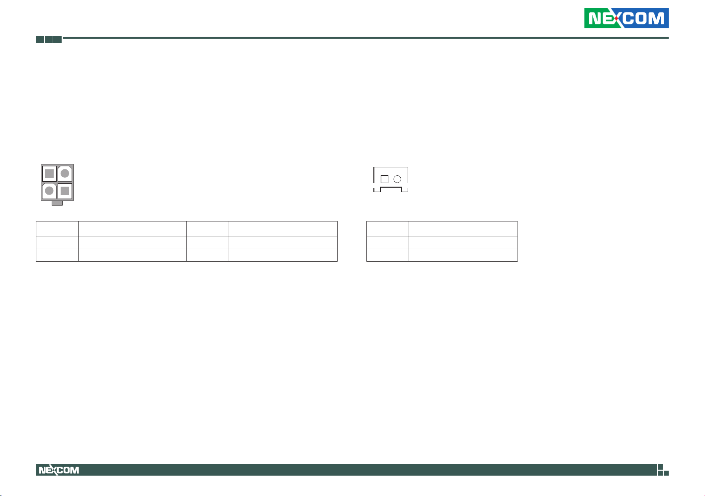
Chapter 2: Jumpers and Connectors
12
34
Connector Pin Definitions
Internal Connectors
PoE Power Connector
Connector type: 2x2 4-pin connector, 4.2mm pitch
Connector location: PWR1
Pin Definition Pin Definition
1 GND 2 GND
3 VIN 4 VIN
Power Button
Connector type: 1x2 JST, 2-pin header, 2.0mm pitch
Connector location: J2
1 2
Pin Definition
1 PWRBTN#
2 GND
Copyright © 2014 NEXCOM International Co., Ltd. All Rights Reserved.
40
IPPC 1560T/1960T/2160P Series User Manual

Chapter 2: Jumpers and Connectors
DC Power Button (AT)
Connector type: 1x2 2-pin header, 2.54mm pitch
Connector location: J3
12
Pin Definition
1 AT_IN
2 VIN_M
COM 4
Connector type: 2x5 10-pin header, 2.0mm pitch
Connector location: CN16
2
1
Pin Definition Pin Definition
1 DCD4 2 RXD4
3 TXD4 4 DTR4
5 GND 6 DSR4
7 RTS4 8 CTS4
9 RI4 10 GND
10
9
Copyright © 2014 NEXCOM International Co., Ltd. All Rights Reserved.
41
IPPC 1560T/1960T/2160P Series User Manual

Chapter 2: Jumpers and Connectors
COM 5
Connector type: 2x5 10-pin header, 2.0mm pitch
Connector location: CN15
2
1
Pin Definition Pin Definition
1 DCD5 2 RXD5
3 TXD5 4 DTR5
5 GND 6 DSR5
7 RTS5 8 CTS5
9 RI5 10 GND
10
9
COM 6
Connector type: 2x5 10-pin header, 2.0mm pitch
Connector location: CN14
2
1
Pin Definition Pin Definition
1 DCD6 2 RXD6
3 TXD6 4 DTR6
5 GND 6 DSR6
7 RTS6 8 CTS6
9 RI6 10 GND
10
9
Copyright © 2014 NEXCOM International Co., Ltd. All Rights Reserved.
42
IPPC 1560T/1960T/2160P Series User Manual

Chapter 2: Jumpers and Connectors
14
USB Connectors
Connector type: 1x4 4-pin header JST, 2.0mm pitch
Connector location: J9 & J10
14
Pin Definition Pin Definition
1 5VSB 2 HUBUSB_DN1
3 HUBUSB_DP1 4 GND
Speaker-out Connector
Connector type: 1x4 4-pin header, 2.0mm pitch
Connector location: JP11
Pin Definition Pin Definition
1 AUDIO-OUT-LR+ 2 AUDIO-OUT-LR-
3 AUDIO-OUT-RR+ 4 AUDIO-OUT-RR-
Copyright © 2014 NEXCOM International Co., Ltd. All Rights Reserved.
43
IPPC 1560T/1960T/2160P Series User Manual

Chapter 2: Jumpers and Connectors
CFast Card Slot
Connector type: Standard CFast connector
Connector location: CN5
S7 PC17PC1S1
Pin Definition Pin Definition
S1 GND PC6 NC
S2 SATA_TXP2 PC7 GND
S3 SATA_TXN2 PC8 TEST POINT
S4 GND PC9 NC
S5 SATA_RXN2 PC10 NC
S6 SATA_RXP2 PC11 NC
S7 GND PC12 NC
PC1 GND PC13 +3.3V
PC2 GND PC14 +3.3V
PC3 NC PC15 GND
PC4 NC PC16 GND
PC5 NC PC17 NC
SATA Connector
Connector type: Standard Serial ATA, 1.27mm pitch
Connector location: CN8
1 7
Pin Definition Pin Definition
1 GND 2 SATA_TXP0
3 SATA_TXN0 4 GND
5 SATA_RXN0 6 SATA_RXP0
7 GND
Copyright © 2014 NEXCOM International Co., Ltd. All Rights Reserved.
44
IPPC 1560T/1960T/2160P Series User Manual

Chapter 2: Jumpers and Connectors
SATA Connector
Connector type: Standard Serial ATA, 1.27mm pitch
Connector location: CN13
1 7
Pin Definition Pin Definition
1 GND 2 SATA_TXP1
3 SATA_TXN1 4 GND
5 SATA_RXN1 6 SATA_RXP1
7 GND
SATA Power Connector
Connector type: 1x2 JST, 2-pin header, 2.5mm pitch
Connector location: J11
1 2
Pin Definition
1 VCC5
2 GND
Copyright © 2014 NEXCOM International Co., Ltd. All Rights Reserved.
45
IPPC 1560T/1960T/2160P Series User Manual

Chapter 2: Jumpers and Connectors
SATA Power Connector
Connector type: 1x2 JST, 2-pin header, 2.5mm pitch
Connector location: J13
1 2
Pin Definition
1 VCC5
2 GND
LVDS Connector A
Connector type: 2x10 20-pin header, 1.25mm pitch
Connector location: CN3
1 19
2 20
Pin Definition Pin Definition
1 LVDS_DDC_CLK 2 LVDS_DDC_DATA
3 Panel_VDD 4 LVDSA_DATA0
5 LVDSA_DATA3 6 LVDSA_DATA#0
7 LVDSA_DATA#3 8 Panel_VDD
9 GND 10 LVDSA_DATA1
11 LVDSA_CLK 12 LVDSA_DATA#1
13 LVDSA_CLK# 14 GND
15 GND 16 Panel_backlight
17 LVDSA_DATA2 18 Panel_backlight
19 LVDSA_DATA#2 20 GND
Copyright © 2014 NEXCOM International Co., Ltd. All Rights Reserved.
46
IPPC 1560T/1960T/2160P Series User Manual

Chapter 2: Jumpers and Connectors
LVDS Connector B
Connector type: 2x10 20-pin header, 1.25mm pitch
Connector location: CN4
1 19
2 20
Pin Definition Pin Definition
1 LVDS_DDC_CLK 2 LVDS_DDC_DATA
3 Panel_VDD 4 LVDSB_DATA0
5 LVDSB_DATA3 6 LVDSB_DATA#0
7 LVDSB_DATA#3 8 Panel_VDD
9 GND 10 LVDSB_DATA1
11 LVDSB_CLK 12 LVDSB_DATA#1
13 LVDSB_CLK# 14 GND
15 GND 16 Panel_backlight
17 LVDSB_DATA2 18 Panel_backlight
19 LVDSB_DATA#2 20 GND
LVDS Panel Inverter Connector
Connector type: 1x7 JST, 7-pin header, 2.5mm pitch
Connector location: J5
7 1
Pin Definition Pin Definition
1 VCC5 2 +12V
3 +12V 4
5 GND 6 GND
7 Panel Backlight Enable
Panel Backlight
Brightness Control
Copyright © 2014 NEXCOM International Co., Ltd. All Rights Reserved.
47
IPPC 1560T/1960T/2160P Series User Manual

Chapter 2: Jumpers and Connectors
51
Touch Panel Control Connector
Connector type: 1x5 5-pin header JST, 2.54mm pitch
Connector location: J6
Pin 4-wire 5-wire
1 Left LL (L)
2 To p UL (Y)
3 N/A Sense (S)
4 Right LR (X)
5 Bottom UR (H)
Pin Definition Pin Definition
1 TOUCH_YD 2 TOUCH_XR
3 SENSE 4 TOUCH_YU
5 TOUCH_XL
SATA/Power LED
Connector type: 1x5 5-pin header JST, 2.0mm pitch
Connector location: J1
5 1
Pin Definition Pin Definition
1 HDDLED# 2 HDDLED
3 GND 4 STBYLED
5 PWRLED
Copyright © 2014 NEXCOM International Co., Ltd. All Rights Reserved.
48
IPPC 1560T/1960T/2160P Series User Manual

Chapter 2: Jumpers and Connectors
14
MCU Debug I/F
Connector type: 1x4 4-pin header, 2.54mm pitch
Connector location: JP1
Pin Definition Pin Definition
1 VCC3 2 MCU_SBWTCK
3 MCU_SBWTDIO 4 GND
MCU LED Indicator Connector
Connector type: 2x5 10-pin header, 2.0mm pitch
Connector location: CN1
2
1
Pin Definition Pin Definition
1 MCU_LSENPW 2 MCU_LED_5
3 MCU_LSEN 4 MCU_LED_4
5 MCU_PIRC 6 MCU_LED_3
7 MCU_BKC 8 MCU_LED_2
9 GND 10 MCU_LED_1
10
9
Copyright © 2014 NEXCOM International Co., Ltd. All Rights Reserved.
49
IPPC 1560T/1960T/2160P Series User Manual

Chapter 2: Jumpers and Connectors
Function Key-in Connector
Connector type: 1x6 6-pin header JST, 2.0mm pitch
Connector location: J4
6 1
Pin Definition Pin Definition
1 MCU_KEYIN_1 2 MCU_SCAN_1
3 MCU_SCAN_2 4 MCU_SCAN_3
5 MCU_SCAN_4 6 MCU_SCAN_5
System FAN2 Connector
Connector type: 1x4 4-pin Wafer, 2.54mm pitch
Connector location: CN19
1 4
Pin Definition Pin Definition
1 GND 2 12V
3 FANIN 4 FANOUT
Copyright © 2014 NEXCOM International Co., Ltd. All Rights Reserved.
50
IPPC 1560T/1960T/2160P Series User Manual

Chapter 2: Jumpers and Connectors
System FAN1 Connector
Connector type: 1x4 4-pin Wafer, 2.54mm pitch
Connector location: CN18
1 4
Pin Definition Pin Definition
1 GND 2 12V
3 SYSFANIN 4 SYSFANOUT
Power Button
Connector type: 1x2 JST, 2-pin header, 2.0mm pitch
Connector location: J7
1 2
Pin Definition
1 HW_R_RST#
2 GND
Copyright © 2014 NEXCOM International Co., Ltd. All Rights Reserved.
51
IPPC 1560T/1960T/2160P Series User Manual

Chapter 2: Jumpers and Connectors
Bluetooth Connector
Connector type: 1x10 10-pin header JST, 1.0mm pitch
Connector location: J8
110
Pin Definition Pin Definition
1 GND 2 USB_6P
3 USB_6N 4 NC
5 NC 6 BT_AUDIO_EN
7 NC 8 BT_3.3V
9 NC 10 GND
Digital I/O
Connector type: 2x8 16-pin header, 2.54mm pitch
Connector location: CN17
2
1
Pin Definition Pin Definition
1 DI0 2 DO0
3 DI1 4 DO1
5 DI2 6 DO2
7 DI3 8 DO3
9 NC 10 NC
11 COM1 12 NC
13 GND 14 GND
15 GND 16 GND
16
15
Copyright © 2014 NEXCOM International Co., Ltd. All Rights Reserved.
52
IPPC 1560T/1960T/2160P Series User Manual

Chapter 2: Jumpers and Connectors
19
21
GPIO
Connector type: 2x5 10-pin header, 2.0mm pitch
Connector location: JP15
0
Pin Definition Pin Definition
1 VCC5 2 GND
3 ICH_GPO0_OUT 4 ICH_GPI0_IN
5 ICH_GPO1_OUT 6 ICH_GPI1_IN
7 ICH_GPO2_OUT 8 ICH_GPI2_IN
9 ICH_GPO3_OUT 10 ICH_GPI3_IN
Bluetooth Connector
Connector type: 1x10 10-pin header JST, 1.0mm pitch
Connector location: JDB1
110
Pin Definition Pin Definition
1 GND 2 SIO_RESET#
3 LPC_PORT80_CLK 4 LPC_FRAME#
5 LPC_AD3 6 LPC_AD2
7 LPC_AD1 8 LPC_AD0
9 VCC3 10 VCC3
Copyright © 2014 NEXCOM International Co., Ltd. All Rights Reserved.
53
IPPC 1560T/1960T/2160P Series User Manual

Chapter 2: Jumpers and Connectors
1
14
13
26
Parallel Port Box Header
Connector type: 2x13 26-pin header, 2.0mm pitch
Connector location: CN12
Pin Definition Pin Definition
1 Line Print Strobe 2 Parallel Data 0
3 Parallel Data 1 4 Parallel Data 2
5 Parallel Data 3 6 Parallel Data 4
7 Parallel Data 5 8 Parallel Data 6
9 Parallel Data 7 10 Acknowledge#
11 Busy 12 Paper empty
13 Select 14 Auto Feed#
15 Error# 16 Initialize#
17 Select Input# 18 GND
19 GND 20 GND
21 GND 22 GND
23 GND 24 GND
25 GND 26 NC
Copyright © 2014 NEXCOM International Co., Ltd. All Rights Reserved.
54
IPPC 1560T/1960T/2160P Series User Manual

Chapter 2: Jumpers and Connectors
Mini-PCIe Connector
Connector location: CN10
12
51 52
Pin Definition Pin Definition
1 WAKE# 2 +3VSB
3 NC 4 GND
5 NC 6 +1.5V
7 CLKREQ# 8 UIM_PWR
9 GND 10 UIM_DATA
11 REF CLK- 12 UIM_CLK
13 REF CLK+ 14 UIM_RESET
15 GND 16 UIM_VPP
17 NC 18 GND
19 NC 20 Disable#
21 GND 22 PERST#
23 PCIERX1N 24 +3VSB
25 PCIERX1P 26 GND
Copyright © 2014 NEXCOM International Co., Ltd. All Rights Reserved.
55
Pin Definition Pin Definition
27 GND 28 +1.5V
29 GND 30 SMBCLK
31 PCIETX- 32 SMBDATA
33 PCIETX+ 34 GND
35 GND 36 USB_5N
37 GND 38 USB_5P
39 +3VSB 40 GND
41 +3VSB 42 NC
43 GND 44 NC
45 NC 46 NC
47 NC 48 +1.5V
49 NC 50 GND
51 NC 52 +3VSB
IPPC 1560T/1960T/2160P Series User Manual

Chapter 2: Jumpers and Connectors
Mini-PCIe Connector
Connector location: CN11
12
51 52
Pin Definition Pin Definition
1 WAKE# 2 +3VSB
3 NC 4 GND
5 NC 6 +1.5V
7 CLKREQ# 8 UIM_PWR
9 GND 10 UIM_DATA
11 REF CLK- 12 UIM_CLK
13 REF CLK+ 14 UIM_RESET
15 GND 16 UIM_VPP
17 NC 18 GND
19 NC 20 Disable#
21 GND 22 PERST#
23 PCIERX1N 24 +3VSB
25 PCIERX1P 26 GND
Copyright © 2014 NEXCOM International Co., Ltd. All Rights Reserved.
56
Pin Definition Pin Definition
27 GND 28 +1.5V
29 GND 30 SMBCLK
31 PCIETX- 32 SMBDATA
33 PCIETX+ 34 GND
35 GND 36 USB_5N
37 GND 38 USB_5P
39 +3VSB 40 GND
41 +3VSB 42 NC
43 GND 44 NC
45 NC 46 NC
47 NC 48 +1.5V
49 NC 50 GND
51 NC 52 +3VSB
IPPC 1560T/1960T/2160P Series User Manual

Chapter 3: System Setup
CAUTION!
Chapter 3: System Setup
Installing a Primary SATA Hard Drive
Prior to removing the chassis cover, make sure the unit’s power
CAUTION!CAUTION!
1. Remove the 4 screws around the HDD cover. 2. Remove the HDD cover.
is off and disconnected from the power sources to prevent
electric shock or system damage.
Copyright © 2014 NEXCOM International Co., Ltd. All Rights Reserved.
57
IPPC 1560T/1960T/2160P Series User Manual

Chapter 3: System Setup
3. Remove the mounting screws on the drive bay. 4. Push toward right and pull up the drive bay.
Copyright © 2014 NEXCOM International Co., Ltd. All Rights Reserved.
58
IPPC 1560T/1960T/2160P Series User Manual

Chapter 3: System Setup
5. Place the SATA hard drive on the drive bay. 6. Use the provided mounting screws to secure the drive in place.
Copyright © 2014 NEXCOM International Co., Ltd. All Rights Reserved.
59
IPPC 1560T/1960T/2160P Series User Manual

Chapter 3: System Setup
7. Push toward right then push down the drive bay into the chassis. 8. Secure the drive bay in the chassis and secure the HDD cover.
Copyright © 2014 NEXCOM International Co., Ltd. All Rights Reserved.
60
IPPC 1560T/1960T/2160P Series User Manual

Chapter 3: System Setup
Installing a Secondary SATA Hard Drive
1. Remove the 6 screws on the right back cover.
Copyright © 2014 NEXCOM International Co., Ltd. All Rights Reserved.
61
IPPC 1560T/1960T/2160P Series User Manual

Chapter 3: System Setup
2. Remove the mounting screws on the drive bay. 3. Place the SATA hard drive on the drive bay.
Copyright © 2014 NEXCOM International Co., Ltd. All Rights Reserved.
62
IPPC 1560T/1960T/2160P Series User Manual

Chapter 3: System Setup
4. Use the provided mounting screws to secure the drive in place. 5. Secure the drive bay in the chassis and replace the right back cover.
Copyright © 2014 NEXCOM International Co., Ltd. All Rights Reserved.
63
IPPC 1560T/1960T/2160P Series User Manual

Chapter 3: System Setup
Installing a CFast Card
1. The CFast card is located on the rear top side of the chassis.
Remove this cover to install CFast card and change battery.
Change this cover to support other interface connector, such as fieldbus.
2. Remove the mounting screw on the cover.
3. Insert the CFast card until it is completely seated in the socket.
Copyright © 2014 NEXCOM International Co., Ltd. All Rights Reserved.
64
IPPC 1560T/1960T/2160P Series User Manual

Chapter 3: System Setup
4. Push the CFast card to remove it.
Copyright © 2014 NEXCOM International Co., Ltd. All Rights Reserved.
65
IPPC 1560T/1960T/2160P Series User Manual

Chapter 3: System Setup
Installing a Mini-PCIe Module
The Mini-PCIe module package includes the following items:
RALINK 802.11b/g/n 2T2R wireless mini card module kit QCOM: Q802XKN5F
Mini-PCIe Module
RF-Cable
3.5G module kit Sierra Wireless MC8705
802.11b/g/n wireless mini card module kit INTEL:2200BNHMW
Antenna
Copyright © 2014 NEXCOM International Co., Ltd. All Rights Reserved.
66
IPPC 1560T/1960T/2160P Series User Manual

Chapter 3: System Setup
Fieldbus Mini-PCIe module
Mini PCIe
Card
Connection
Cable
Connector Board
Dual RJ45
DB9 PROFIBUS
5-pin
Connector
PROFINET
EtherNet/IP
EtherCAT
DeviceNet
Copyright © 2014 NEXCOM International Co., Ltd. All Rights Reserved.
67
IPPC 1560T/1960T/2160P Series User Manual

Chapter 3: System Setup
Universal PROFIBUS I/O Bracket IPPC xx60 Series Special PROFIBUS I/O Bracket
Universal DeviceNet I/O Bracket IPPC xx60 Series Special DeviceNet I/O Bracket
Universal PROFINET, EtherNET/IP and EtherCAT I/O Bracket IPPC xx60 Series Special PROFINET, EtherNET/IP and EtherCAT I/O Bracket
Copyright © 2014 NEXCOM International Co., Ltd. All Rights Reserved.
68
IPPC 1560T/1960T/2160P Series User Manual

Chapter 3: System Setup
If you are installing the 802.11b/g/n INTEL: 2200BNHMW mini card module
(half size), before processing with the installation, please assemble the Wi-Fi
module bracket first to full size module by following the instructions below:
1. Align the mounting holes on the Wi-Fi mini card module to the mounting
holes on the Wi-Fi module bracket.
Wi-Fi module bracketMounting holes
2. Tighten screws onto the mounting holes to secure the bracket.
Copyright © 2014 NEXCOM International Co., Ltd. All Rights Reserved.
69
IPPC 1560T/1960T/2160P Series User Manual

Chapter 3: System Setup
3. Insert the Mini-PCIe module into the Mini-PCIe slot at the 45 degrees
angle until the gold-plated connector on the edge of the module
completely disappear inside the slot.
Mini-PCIe
Slot
Mini-PCIe Module
4. Secure the module with mounting screws.
Copyright © 2014 NEXCOM International Co., Ltd. All Rights Reserved.
70
IPPC 1560T/1960T/2160P Series User Manual

Chapter 3: System Setup
5. Wi-Fi or 3G Mini-PCIe module:
A. Remove the left back cover.
Copyright © 2014 NEXCOM International Co., Ltd. All Rights Reserved.
71
IPPC 1560T/1960T/2160P Series User Manual

Chapter 3: System Setup
B. Attach one end of the RF cables onto the module. C. Remove the antenna hole block.
Copyright © 2014 NEXCOM International Co., Ltd. All Rights Reserved.
72
IPPC 1560T/1960T/2160P Series User Manual

Chapter 3: System Setup
D. Insert the ring onto the antenna jack end of the cable.
Antenna jack
Ring
Copyright © 2014 NEXCOM International Co., Ltd. All Rights Reserved.
73
IPPC 1560T/1960T/2160P Series User Manual

Chapter 3: System Setup
E. Connect external antennas to the antenna jacks.
Copyright © 2014 NEXCOM International Co., Ltd. All Rights Reserved.
74
IPPC 1560T/1960T/2160P Series User Manual

Chapter 3: System Setup
F. 3G Mini-PCIe module.
Copyright © 2014 NEXCOM International Co., Ltd. All Rights Reserved.
75
IPPC 1560T/1960T/2160P Series User Manual

Chapter 3: System Setup
6. Fieldbus Mini-PCIe module.
A. Remove the Universal Fieldbus I/O cover or the Optional I/F cover.
B. Secure the Universal FBI I/O bracket or the Special FBI I/O bracket.
Copyright © 2014 NEXCOM International Co., Ltd. All Rights Reserved.
76
IPPC 1560T/1960T/2160P Series User Manual

Chapter 3: System Setup
C. Plug the FBI Cable to the I/O connector board.
DB9 Connector Board Dual RJ45 Connector Board
5-pins Connector Board
Copyright © 2014 NEXCOM International Co., Ltd. All Rights Reserved.
77
IPPC 1560T/1960T/2160P Series User Manual

Chapter 3: System Setup
D. Plug the FBI Cable to the FBI Mini-PCIe card.
Copyright © 2014 NEXCOM International Co., Ltd. All Rights Reserved.
78
IPPC 1560T/1960T/2160P Series User Manual

Chapter 3: System Setup
Copyright © 2014 NEXCOM International Co., Ltd. All Rights Reserved.
79
IPPC 1560T/1960T/2160P Series User Manual

Chapter 3: System Setup
E. Stick the FBI protocol labels to the corresponding interfaces.
Copyright © 2014 NEXCOM International Co., Ltd. All Rights Reserved.
80
IPPC 1560T/1960T/2160P Series User Manual

Chapter 3: System Setup
Installing a Riser Card
The riser card package includes the following items:
1 PCI and 1 PCIe x4 (Default Installation) 2 PCI riser card
2 PCIe x4 riser card
Copyright © 2014 NEXCOM International Co., Ltd. All Rights Reserved.
81
IPPC 1560T/1960T/2160P Series User Manual

Chapter 3: System Setup
1. Remove the 6 screws on the back heatsink cover. 2. Remove the back heatsink cover.
Copyright © 2014 NEXCOM International Co., Ltd. All Rights Reserved.
82
IPPC 1560T/1960T/2160P Series User Manual

Chapter 3: System Setup
3. Remove the right back cover. 4. Remove the 4 plastic screws.
Copyright © 2014 NEXCOM International Co., Ltd. All Rights Reserved.
83
IPPC 1560T/1960T/2160P Series User Manual
 Loading...