


Single Board Computer
EBC340
User’s Manual
Apr.-01-2009 Build
User’s Manual is subject to change without prior notice.
For any update, please visit our website: www.nexcom.com
k

EBC340 User’s Manual 2 Table of Content
Preface
Copyright
This publication, including all photographs, illustrations and software, is protected under international copyright laws,
with all rights reserved. No part of this manual maybe reproduced, copied, translated or transmitted in any form or by
any means without the prior written consent from NEXCOM International Co., Ltd.
Version 1.3 Copyright 2006
Disclaimer
The information in this document is subject to change without prior notice and does not represent commitment from
NEXCOM International Co., LTD. However, users may update their knowledge of any product in use by constantly
checking its manual posted on our website: http://www.nexcom.com. NEXCOM shall not be liable for direct, indirect,
special, incidental, or consequential damages arising out of the use of any product, nor for any infringements upon
the rights of third parties, which may result from such use. Any implied warranties of merchantability of fitness for any
particular purpose is also disclaimed.
Acknowledgements
The EBC 340 series is a trademark of NEXCOM international CO., LTD. All other product names mentioned herein
are registered trademarks of their respective owners.
Regulatory Compliance Statements
This section provides the FCC compliance statement for Class A devices and describes how to keep the system CE
compliant.
Federal Communications Commission (FCC) For Class A Device
This equipment has been tested and verified to comply with the limits for a Class A digital device, pursuant to Part 15
of FCC Rules. These limits are designed to provide reasonable protection against harmful interference when the
equipment is operated in a commercial environment. This equipment generates, uses, and can radiate radio
frequency energy and, if not installed and used in accordance with the instructions, may cause harmful interference to
radio communications. Operation of this equipment in a residential area (domestic environment) is likely to cause

EBC340 User’s Manual 3 Table of Content
harmful interference, in which case the user will be required to correct the interference (take adequate measures) at
their own expense.
CE Certification
The product(s) described in this manual complies with all applicable European Union (CE) directives if it has a CE
marking. For computer systems to remain CE compliant, only CE-compliant parts may be used. Maintaining CE
compliance also requires proper cable and cabling techniques.
Safety Information
Before installing and using the EBC340, note the following precautions:
Read all instructions carefully. Do not place the unit on an unstable surface, cart, or stand.
Follow all warnings and cautions in this manual.
As parts replaced for sure that your service technician uses parts specified by the manufacturer.
Avoid using the system near water, in direct sunlight, or near a hearing device.
WARNINGS
Read and adhere to all warnings, cautions, and notices in this guide and the
documentation supplied with the chassis, power supply, and accessory modules. If
the instructions for the chassis and power supply are inconsistent with these
instructions or the instructions for accessory modules, contact the supplier to find
out how you can ensure that your computer meets safety and regulatory
requirements.
CAUTION
Electrostatic discharge (ESD) can damage NSA components. Do the described
procedures only at an ESD workstation. If no such station is available, you can
provide some ESD protection by wearing an antistatic wrist strap and attaching it to
a metal part of the computer chassis.

EBC340 User’s Manual 4 Table of Content
Table of Content
Preface……………...……………..……………………………………….………….……..……………..2
Copyright………………..……………………………………….……………………………………….... 2
Disclaimer………………………..………………………………..……………………………………….. 2
Acknowledgements……………………………………………..………………………..………..…..…… 2
Regulatory Compliance Statements……………………..…………………………………….……………2
Federal Communications Commission (FCC) For Class A Device……………..……….…………..…..…2
CE Certification………………………………………………………………………….……….………...3
Safety Information……………………………………………………………………….………..………..3
Table of Content……………………………………………………………………………………....……. 4
Chapter 1 General Information
1.1 Specification…………………………………………………….…………………………………….. 7
1.2 Power Consumption Measurement……………………………………………………………………..9
1.3 Board Layout…………………………………………………………………….… ………………… 10
1.4 Board Dimensions……………………………………………………….……… …….………...…… 10
Chapter 2 Jumper Setting
2.1 Before You Begin……………………………………………..….……………………………………12
2.2 Precautions………………………………………………………………………………………... …..12
2.3 Setting Jumpers…………………………………………………………………………………… …..13
2.4 Location of Jumpers………………………………………………………………………………. …..14
2.5 Function of Jumpers and Connectors…………….………………………………………………........15
Chapter 3 Expansion
3.1 System Memory…………………………………………………………………………………..…….30
3.2 Installing Compact Flash……………….……...………………………………………..…………….. 31
Chapter 4 BIOS Setting
4.1 Entering Setup………………………………………………………………………………………….33
4.2 Getting Help……………………………………………………………………………………………33
4.3 The Main Menu………………………………………………………………………………………...35

EBC340 User’s Manual 5 Chapter 1
Chapter 1
General Information
EBC340 User’s Manual 6 Chapter 1
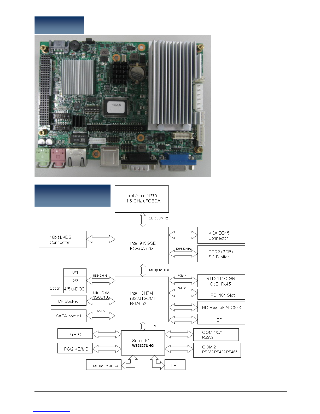
Block Diagram

EBC340 User’s Manual 7 Chapter 1
1.1 Specification
CPU Support
Intel® Atom™ Processor N270 1.6GHZ
Main Memory
1 x DDR2 SO-DIMM Socket (up to 2GB SO-DIMM memory)
Chipset
Intel 82945GSE Graphic Controller Hub (GMCH)
Intel® 82801GBM ICH7 Mobile (ICH7-M)
Display
Intel® 945GSE integrated 3D graphic engine GMA950
Support Dual Independent Display: CRT+LVDS
CRT: 1 x DB15 VGA CON
LVDS: 1x DF13 20-pin connector
Analog VGA interface:
Resolution up to 1600x1200 at 85 Hz, 2048x1536 at 75Hz
LVDS interface:
Support 18-bit single channel LVDS, resolution up to 1600x1200
CCFL interface:
1 x CCFL for LCD Panel Backlight Inverter
Storage
SATA: 1x Serial ATA ports
U-DOC : By option
CF: 1x Compact Flash Socket
Expansion
1x PCI-104 Slot
Audio
Realtek ALC888 CODEC for High Definition
1x Mic-In / 1x Line out Phone Jack
On board LAN
LAN Chip: Realtek RTL8111C-GR PCI Express Gigabit Ethernet
Support Boot From LAN (PXE)
1x RJ45 connector w/ LED
I/O Interface
Parallel port :1 x Parallel Port 26-pin Box header
Serial port: 4 ports, 1x DB9 port, three 2x5-pin Box headers
SIO2 support RS232/422/485 w/10pin Box header
USB 2.0 : 6 ports, 2x edge ports and 2 ports by Jst connector

EBC340 User’s Manual 8 Chapter 1
8 GPIO lines via header (GPI 0~3 and GPO 0~3)
1 x Power LED and 1 x HDD Active LED Pin header
1 x DB15 VGA port
1x Keyboard/Mouse pin header
Onboard Buzzer / SMBus 2.0 /Reset SW
Power Input
Support AT mode only
6-pin power connector for +5V / +12V power in
3-pin Jst connector with PS_ON# directly connected to GND for ATX power supply
(Without power on push button function)
System Management
Monitoring of 4 voltages (Vcore,+12V, +3.3V, +1.5V)
2 Temperatures (CPU, System)
On board RTC
On chip RTC with battery back up / External Li-ion Battery
RTC Torrance less than 2sec (24 hours) under 25˚C
BIOS
Award system BIOS
8M bits SPI ROM
Environment
Operating temperatures: 0°C to 60°C
Storage temperatures:-20˚C to 85˚C
Relative Humidity: Operating 10%~90%, non-condensing
Certifications
CE
FCC Class A

EBC340 User’s Manual 9 Chapter 1
1.2 Power Consumption Measurement
Power Type
+12V +5v
+12v-to-Vcore
DC/DC
+12v-to-1.8v
DC/DC
+12v-to-0.9v
DC/DC
5v-to-1.5v
DC/DC
5v-to-1.05v
DC/DC
+12v-to-3.3v
DC/DC
Consumed watts
18W 34.75W
4.4W 5.544W 0.9W 5.79W 7.581W 19W
Consumed currents (Item A )
1.5A 6.95A
0.367A 0.462A 0.075A 1.158A 1.5162A
1.584A
Actually required currents
(Item A/0.80 )
0.46A 0.578A 0.01A 1.448A 1.896A 1.98A
12v needed
4.528A
5v needed
10.294A

EBC340 User’s Manual 10 Chapter 1
1.3 Board Layout
Figure 1.2: Overview of EBC 340
1.4 Board Dimensions
Figure 1.3: Mechanical Drawing of the EBC 340

EBC 340 User’s Manual 11
Chapter 2
Jumper Setting

EBC 340 User’s Manual 12
This chapter of the User’s Manual describes how to set jumpers.
Note: The procedures that follow are generic for all EBC340.
2.1 Before You Begin
Ensure you have a stable, clean working environment. Dust and dirt can get into components
and cause a malfunction. Use containers to keep small components separated.
Adequate lighting and proper tools can prevent you from accidentally damaging the internal
components. Most of the procedures that follow require only a few simple tools, including the
following:
A Philips screwdriver
A flat-tipped screwdriver
A set of jewelers Screwdrivers
A grounding strap
An anti-static pad
Using your fingers can disconnect most of the connections. It is recommended that you do not
use needle-nosed pliers to disconnect connections as these can damage the soft metal or plastic
parts of the connectors.
Before working on internal components, make sure that the power is off. Ground yourself before
touching any internal components, by touching a metal object. Static electricity can damage
many of the electronic components. Humid environment tend to have less static electricity than
dry environments. A grounding strap is warranted whenever danger of static electricity exists.
2.2 Precautions
Computer components and electronic circuit boards can be damaged by discharges of static
electricity.
Working on the computers that are still connected to a power supply can be extremely
dangerous. Follow the guidelines below to avoid damage to your computer or yourself:
Always disconnect the unit from the power outlet whenever you are working inside the case.
If possible, wear a grounded wrist strap when you are working inside the computer case.
Alternatively, discharge any static electricity by touching the bare metal chassis of the unit
case, or the bare metal body of any other grounded appliance.
Hold electronic circuit boards by the edges only. Do not touch the components on the board
unless it is necessary to do so. Don’t flex or stress the circuit board.
Leave all components inside the static-proof packaging that they shipped with until they are

EBC 340 User’s Manual 13
ready for installation.
Use correct screws and do not over tighten screws.
2.3 Setting Jumpers
A jumper is the simplest kind of electric switch. It consists of two metal pins and a cap. When
setting the jumpers, ensure that the jumper caps are placed on the correct pins. When the
jumper cap is placed on both pins, the jumper is SHORT. If you remove the jumper cap, or place
the jumper cap on just one pin, the jumper is OPEN. Please see the following illustrations
The illustrations on the right
show a 2-pin jumper. When the
jumper cap is placed on both
pins, the jumper is SHORT. If
you remove the jumper cap, or
place the jumper cap on just
one pin, the jumper is OPEN.
Open (Off) Short (On)
These illustrations show a
3-pin jumper. Pins 1 and 2 are
SHORT.
Table 2-1: Setting Jumpers

EBC 340 User’s Manual 14
2.4 Location of Jumpers
Figure 2-1: Jumper Location

EBC 340 User’s Manual 15
2.5 Functions of Jumpers and Connectors
VGA Port
VGA1 (D-Sub 15 pins)
Pin Definition: VGA1
Pin NO. Description Pin NO.
Description
1 RED_VGA 9 VGA_VCC
2 GREEN_VGA 10 GND
3 BLUE_VGA 11 NC
4 NC 12 VGA_DDC_DATA
5 GND 13 G_HSYNC
6 GND 14 G_VSYNC
7 GND 15 VGA_DDC_CLK
8 GND
LVDS CON
CN6 ( 2 X10 2.0 Pitch)
Pin Definition: CN6
Pin NO. Description Pin NO. Description
1 DDCCLK 11 LB_CLK_P
2 DDC_DATA 12 LB_DATAN1
3 VDD 13 LB_CLK_N
4 LB_DATAP0 14 GND
5 PULL LOW 15 GND
6 LB_DATAN0 16 VCC12_INV
7 PULL LOW 17 LB_DATAP2
8 VDD 18 VCC12_INV
9 GND 19 LB_DATAN2
10 LB_DATAP1 20 GND
EBC 340 User’s Manual 16
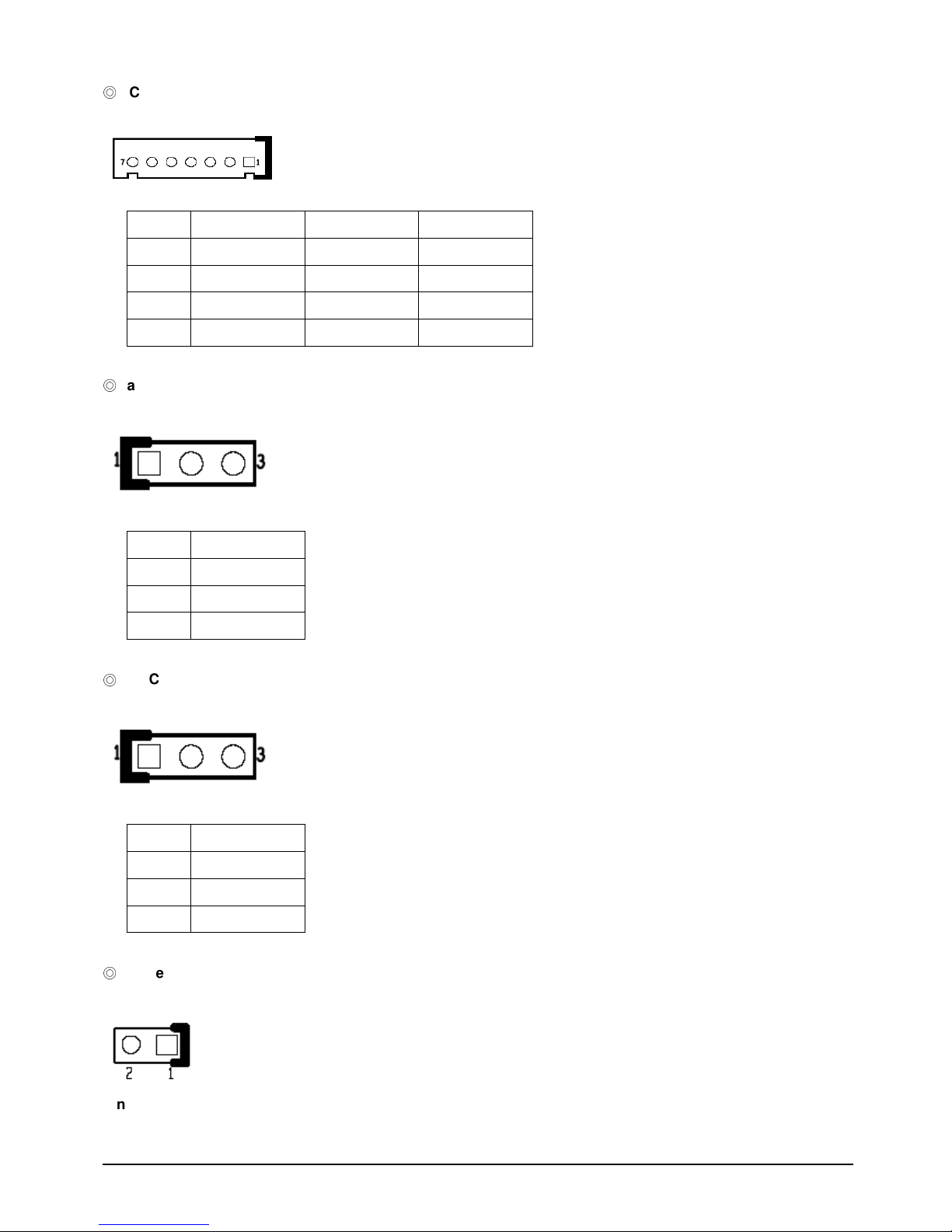
CCFL CON
J4 (JST 7 Pins 2.54 Pitch)
Pin Definition: J4
Pin NO. Description Pin NO. Description
1 +5V 2 +12V
3 +12V 4 Brightness Ctrl
5 GND 6 GND
7 Backlight Enable
Panel Power selection:
Pin header 1x3 2.54 Pitch.
Pin Definition: JP8
Pin NO. Description
1 VCC5
2 Panel power
3 VCC3
RTC Clear:
Pin header 1x3 2.54 Pitch.
Pin Definition: JP2
Pin NO. Description
1 Battery 3.3V
2 RTCRST#
3 GND
Reset Button:
Pin header 1x2 2.0 Pitch.
Pin Definition: JP1
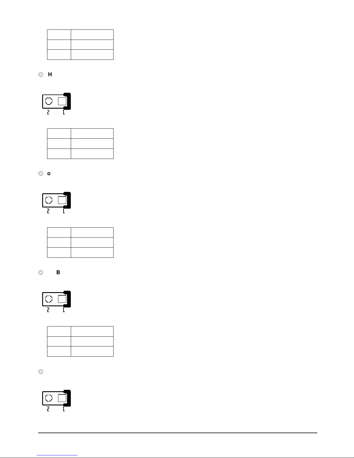
EBC 340 User’s Manual 17
Pin NO. Description
1 RESET#
2 GND
HDD Active LED:
Pin header 1x2 2.0 Pitch.
Pin Definition: JP3
Pin NO. Description
1 VCC5
2 HD_LED#
Power LED:
Pin header 1x2 2.0 Pitch.
Pin Definition: JP4
Pin NO. Description
1 VCC5
2 GND
SMBus:
Pin header 1x2 2.0 Pitch.
Pin Definition: JP5
Pin NO. Description
1 SMB_DATA
2 SMB_CLK
LAN Active LED
Pin header 1x2 2.0 Pitch.
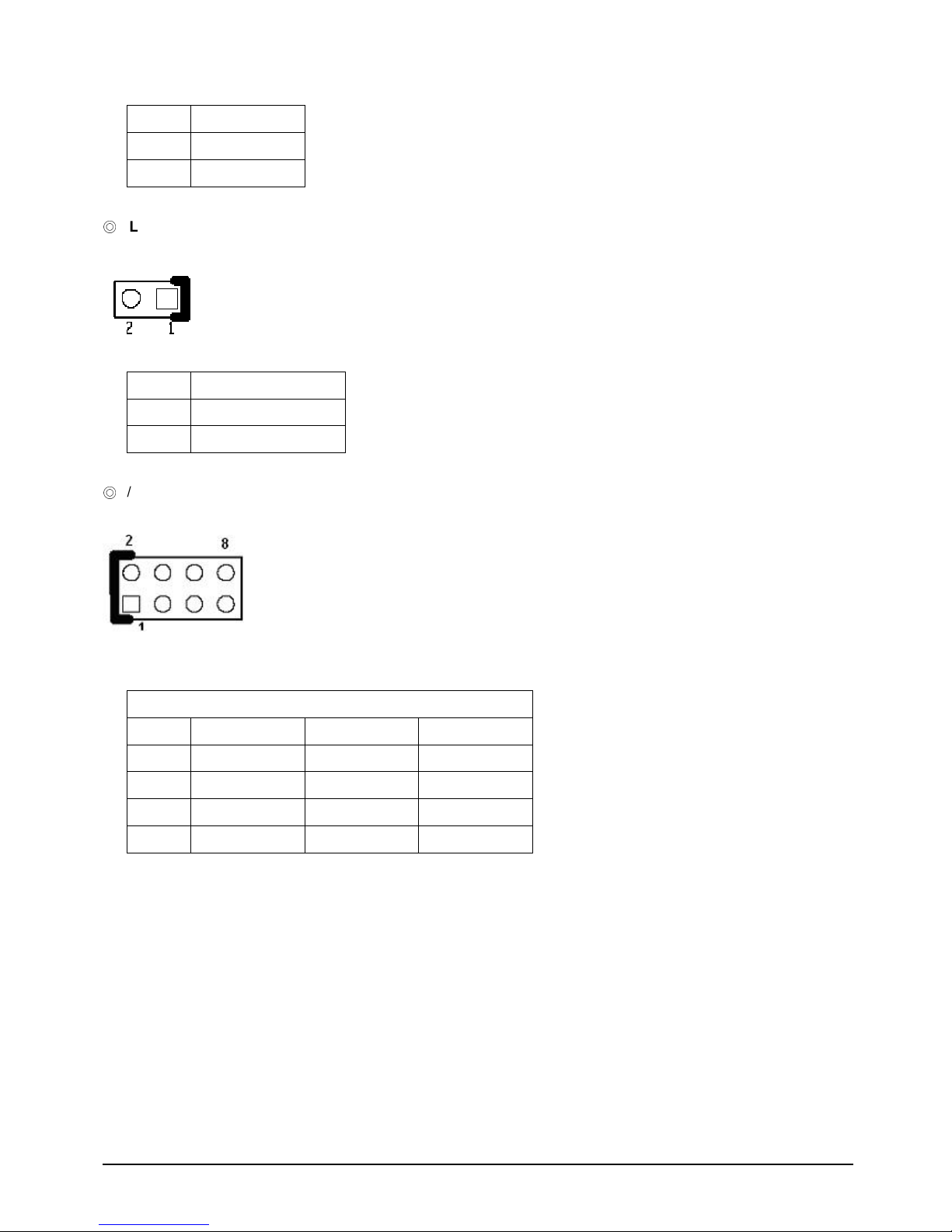
EBC 340 User’s Manual 18
Pin Definition: JP6
Pin NO. Description
1 VCC3
2
LAN1_ACTLED#
LAN Link LED
Pin header 1x2 2.0 Pitch.
Pin Definition: JP7
Pin NO.
Description
1 VCC3
2
LAN1_LINKLED#
P/S 2 Keyboard / Mouse
Pin header 2x4 2.54 Pitch.
Pin Definition: JP9
KM1 for Keyboard/ Mouse:
Pin NO. Description Pin NO. Description
1 VCC5 2 VCC5
3 KB_DATA 4 LM_DATA
5 KB_CLK 6 LM_CLK
7 GND 8 GND

EBC 340 User’s Manual 19
PCI104
Connector
A. Connector size: 4X30 pin
B. Connector location: CN1
C. Connector pin definition
Pin Signal Pin Signal
PA1 GND PC1 VCC5
PA2 VIO PC2 PCI_AD1
PA3 PCI_AD5 PC3 PCI_AD4
PA4 PCI_CBE#0 PC4 GND
PA5 GND PC5 PCI_AD8
PA6 PCI_AD11 PC6 PCI_AD10
PA7 PCI_AD14 PC7 GND
PA8 VCC3 PC8 PCI_AD15
PA9 PCI_SERR# PC9 NC
PA10 GND PC10 VCC3
PA11 PCI_STOP# PC11 PCI_LOCK#
PA12 VCC3 PC12 GND
PA13 PCI_FRAME# PC13 PCI_IRDY#
PA14 GND PC14 VCC3
PA15 PCI_AD18 PC15 PCI_AD17
PA16 PCI_AD21 PC16 GND
PA17 VCC3 PC17 PCI_AD22
PA18 PCI_104_IDSEL0
PC18 PCI_104_IDSEL1
PA19 PCI_AD24 PC19 VIO
PA20 GND PC20 PCI_AD25
PA21 PCI_AD29 PC21 PCI_AD26
PA22 VCC5 PC22 GND
PA23 PCI_REQ#2 PC23 PCI_REQ#3
PA24 GND PC24 VCC5
PA25 PCI_GNT#3 PC25 PCI_GNT#4
PA26 VCC5 PC26 GND
PA27 PCI_CLK2 PC27 PCI_CLK3
PA28 GND PC28 VCC5

EBC 340 User’s Manual 20
PA29 VCC12 PC29 PCI_IRQ#F
PA30 VCC12N PC30 PCI_GNT#5
PB1 NC PD1 PCI_AD0
PB2 PCI_AD2 PD2 VCC5
PB3 GND PD3 PCI_AD3
PB4 PCI_AD7 PD4 PCI_AD6
PB5 PCI_AD9 PD5 GND
PB6 VIO PD6 GND
PB7 PCI_AD13 PD7 PCI_AD12
PB8 PCI_CBE#1 PD8 VCC3
PB9 GND PD9 PCI_PAR
PB10 PCI_PERR# PD10 NC
PB11 VCC3 PD11 GND
PB12 PCI_TRDY# PD12 PCI_DEVSEL#
PB13 GND PD13 VCC3
PB14 PCI_AD16 PD14 PCI_CBE#2
PB15 VCC3 PD15 GND
PB16 PCI_AD20 PD16 PCI_AD19
PB17 PCI_AD23 PD17 VCC3
PB18 GND PD18 PCI_104_IDSEL2
PB19 PCI_CBE#3 PD19 PCI_104_IDSEL3
PB20 PCI_AD26 PD20 GND
PB21 VCC5 PD21 PCI_AD27
PB22 PCI_AD30 PD22 PCI_AD31
PB23 GND PD23 VIO
PB24 PCI_REQ#4 PD24 PCI_GNT#2
PB25 VIO PD25 GND
PB26 PCI_CLK0 PD26 PCI_CLK1
PB27 VCC5 PD27 GND
PB28 PCI_IRQ#H PD28 PCI_RST#
PB29 PCI_IRQ#E PD29 PCI_IRQ#G
PB30 PCI_REQ#5 PD30 GND
D. PCI routing :
AD20 : E F G H
AD21 : H E F G
AD22 : G H E F
AD23 : F G H E
EBC 340 User’s Manual 21
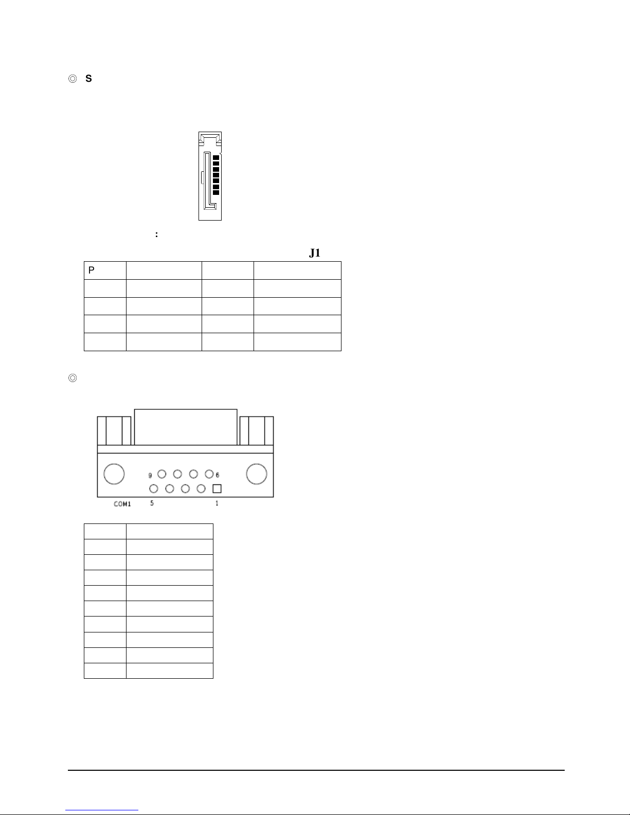
SATAII ports
J1 Standard Serial ATAII 1.27mm connector
Pin definition
J1
Pin NO. Description Pin NO. Description
1 GND 2 TXP0
4 GND 3 TXN0
7 GND 5 RXN0
6 RXP0
COM 1
Connector location: JP1
Connector pin definition
Pin Signal
1 DCD
2 RXD
3 TXD
4 DTR
5 GND
6 DSR
7 RTS
8 CTS
9 RI
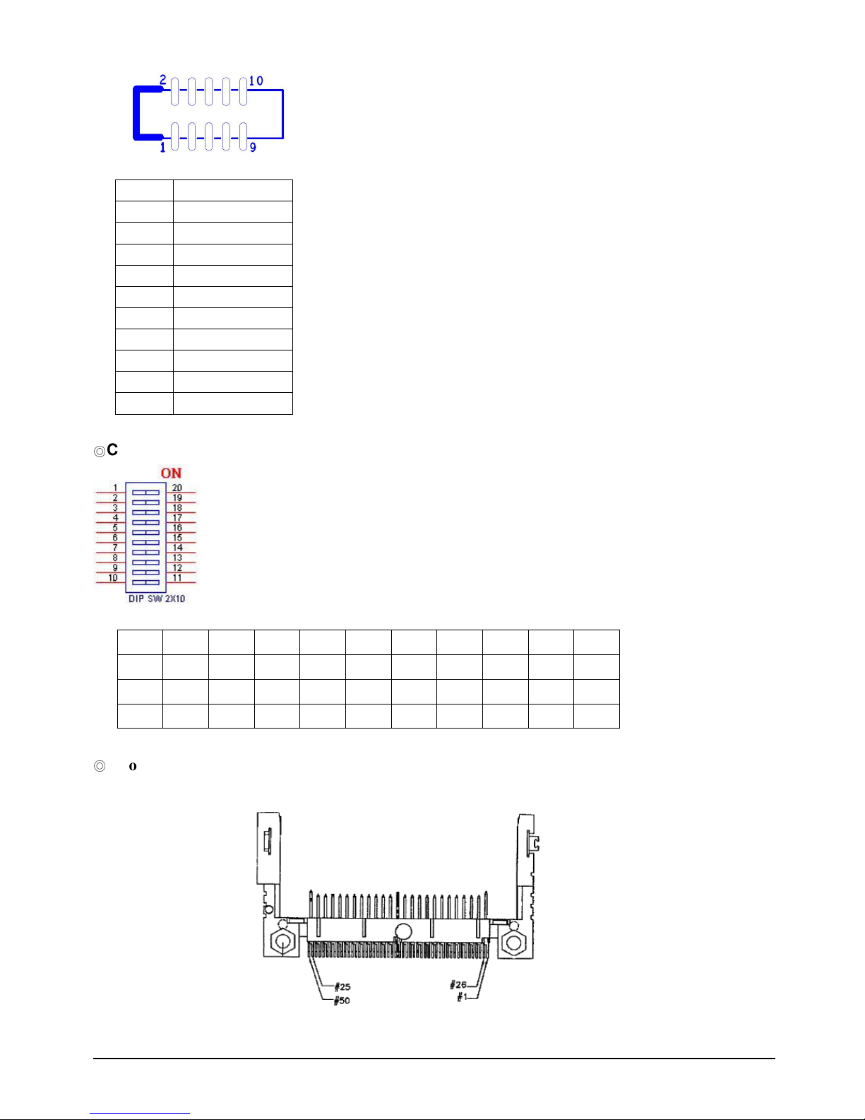
COM 2~4:
Box header 2x5 2.0 Pitch
CN4 , CN2 , CN3
1
7
EBC 340 User’s Manual 22
Connector pin definition
Pin Signal
1 DCD
2 RXD
3 TXD
4 DTR
5 GND
6 DSR
7 RTS
8 CTS
9 RI
10 NC
COM2 selection:
SW1. 1-20 2-19 3-18 4-17 5-16 6-15 7-14 8-13 9-12 10-11
RS232 OFF OFF OFF ON OFF ON OFF OFF OFF OFF
RS422 OFF OFF ON OFF ON OFF ON ON ON ON
RS485 ON ON OFF ON ON OFF OFF OFF OFF ON
Compact Flash
CN10 (Compact Flash TYPE 2)
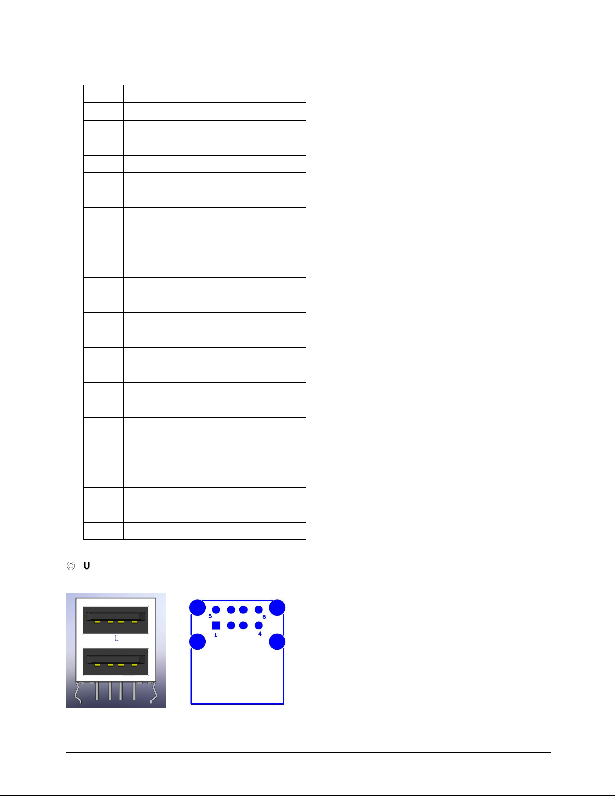
EBC 340 User’s Manual 23
Pin Definition:
Pin NO. Description Pin NO. Description
1 GND 2 SDD3A
3 SDD4A 4 SDD5A
5 SDD6A 6 SDD7A
7 SDCS#1 8 GND
9 GND 10 GND
11 GND 12 GND
13 VCC 14 GND
15 GND 16 GND
17 GND 18 SDA2A
19 SDA1A 20 SDA0A
21 SDD0A 22 SDD1A
23 SDD2A 24 NC
25 CF_CD2# 26 CF_CD1#
27 SDD11A 28 SDD12A
29 SDD13A 30 SDD14A
31 SDD15A 32 SDCS#3
33 NC 34 SDIOR#
35 SDIOW# 36 VCC
37 HDIRQ14 38 VCC
39 CF_SEL# 40 NC
41 IDERST# 42 SIORDY
43 SDREQ 44 SDDACK#
45 IDEACTP# 46 DIAG#
47 SDD8A 48 SDD9A
49 SDD10A 50 GND
USB Port
CN7 Dual USB port.
Pin Definition:
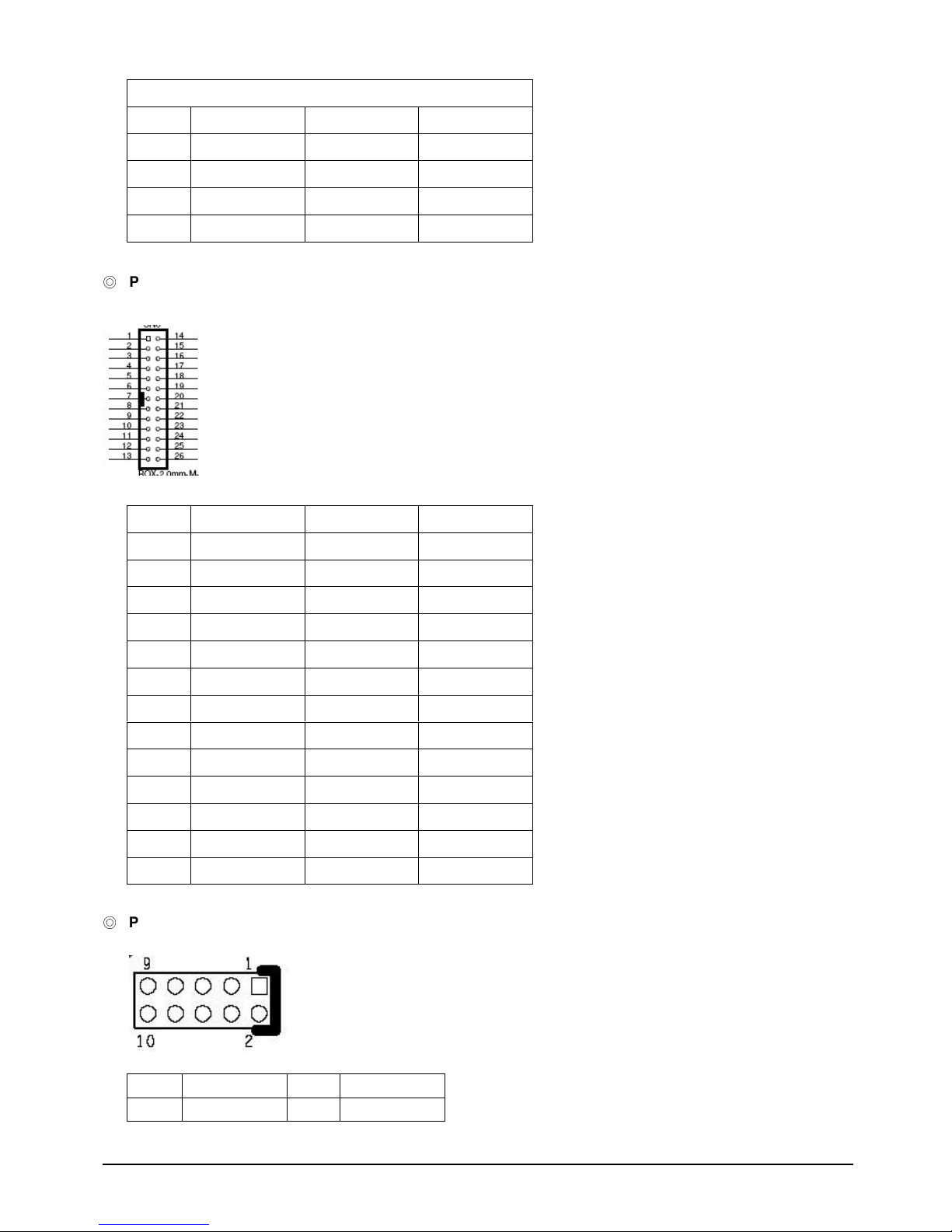
EBC 340 User’s Manual 24
CN7:
Pin NO. Description Pin NO. Description
1 P5V_USB_P01
5 P5V_USB_P01
2 USB0- 6 USB13 USB0+ 7 USB1+
4 GND 8 GND
Parallel Interface
CN5 (2.0mm Box Header)
Pin Definition: CN5
Pin NO. Description Pin NO. Description
1 STB# 14 AFD2 PD0 15
ERR-
3 PD1
16
INIT-
4 PD2
17
SLIN-
5 PD3
18
GND
6 PD4
19
GND
7 PD5
20
GND
8 PD6
21
GND
9 PD7
22
GND
10 ACK- 23
GND
11 BUSY 24
GND
12 PE 25 GND
13 SLCT 26 NC
GPIO connector
2 x 5 2.0mm Pin header
Pin Definition: J5
1 VCC5 2 GND
3 SIO_GPI54 4 SIO_GPO50
EBC 340 User’s Manual 25
5 SIO_GPI55 6 SIO_GPO51
7 SIO_GPI56 8 SIO_GPO52
9 SIO_GPI57 10 SIO_GPO53
USB Jst
Connector
JST 6 Pins 2.0 Pitch
Pin Definition: J6
Pin NO.
Description
1 P5V_USB_P23
2 USB23 USB2+
4 USB35 USB3+
6 GND
SYSTEM FAN.
FAN (Wafer-2.54mm Male 180)
Pin Definition: FAN1
Pin NO. Description
1 GND
2 12V
3 SENSE
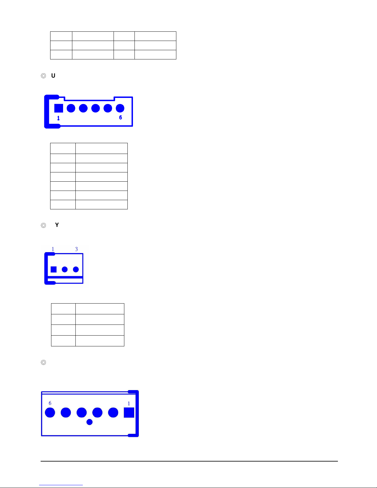
DC Power input Connector:
1x 6 Pin Power connector:

EBC 340 User’s Manual 26
Pin Definition: J2
Pin NO. Description
1 VCC12
2 GND
3 GND
4 GND
5 VCC5
6 VCC5
ATX power supply connector
1X3 JST 2.5mm Connector
Pin Definition: J3
Pin NO. Description
1 NC
2 GND
3 PS_ON# to GND
USB DOM Connector: ( By Option )
Pin Header 2x5 2.54mm Pitch
Pin Definition: J7
Pin Signal Pin Signal
1 P5V_USB_P45
2 P5V_USB_P45
3 USB4- 4 USB5-
5 USB4+ 6 USB5+
7 GND 8 GND
9 NC 10 uDOC_OC#

EBC 340 User’s Manual 27
Line-Out Connector:
CN8 Phone Jack
Pin NO.
ON
1 GND
2 LOUT_R
3 NC
4 NC
5 LOUT_L
Mic-In Connector:
CN9 Phone Jack
Pin NO.
ON
1 GND
2 MIC_R
3 NC
4 NC
5 MIC_L

EBC 340 User’s Manual 28
LAN1 connector:
A. Connector size: RJ45+LED
B. Connector location: CN8
C. Connector pin definition
Pin Signal Pin Signal
1 LAN1_TXD0P 2 LAN1_TXD0N
3 LAN1_TXD1P 4 LAN1_TXD2P
5 LAN1_TXD2N 6 LAN1_TXD1N
7 LAN1_TXD3P 8 LAN1_TXD3N
9 LAN1_LINKLED# 10 VCC3
11 LAN1_ACTLED# 12 VCC3
MH1 GND_CHASSIS MH2 GND_CHASSIS

EBC 340 User’s Manual 29
Chapter 3
Expansion

EBC 340 User’s Manual 30
3.1 System Memory
EBC 340 incorporates Intel 945GSE Express chipset chipset supports up to 2GB un-buffered
non-ECC DDR2 SDRAM.
Installing memory
1.To install a memory into socket,insert it to socket notches.
2.To press the memory down until completely seated within the springs.

EBC 340 User’s Manual 31
3.2 Installing Compact Flash
1. To install a Compact Flash memory card into EBC 320-JB, align the notches on the card with
the Compact Flash socket in the EBC 320-JB. Then firmly insert the card into the socket until it
is completely seated.
Figure 3-5: How to Install Compact Flash Memory (1)
2. To remove the Compact Flash memory card from EBC 340, pull out the memory card from the
Compact Flash socket.
Figure 3-6: How to Uninstall Compact Flash Memory (2)

EBC 340 User’s Manual 32
Chapter 4
BIOS Setting
EBC 340 User’s Manual 33
AWARD BIOS Setup
Award's BIOS ROM has a built-in Setup program that allows users to modify the basic system
configuration. This type of information is stored in battery-backed RAM (CMOS RAM) so that it
retains the Setup information when the power is turned off.
The Chapter shows the currently BIOS setup picture is for reference only, which may
change by the BIOS modification in the future. Any Major updated items or re-version,
user can download from NEXCOM web site http://www.nexcom.com.tw or any unclear
message, can contact NEXCOM Customer Service people for help
http://www.nexcom.com.tw/contact/contact.htm
4.1 Entering Setup
Power on the computer and press <Del> immediately will allow you to enter Setup. The other
way to enter Setup is to power on the computer, when the below message appears briefly at
the bottom of the screen during the POST (Power On Self Test), press <Del> key
TO ENTER SETUP BEFORE BOOT
PRESS <DEL> KEY
4.2 Getting Help
Main Menu
The on-line description of the highlighted setup function is displayed at the bottom of the
screen.
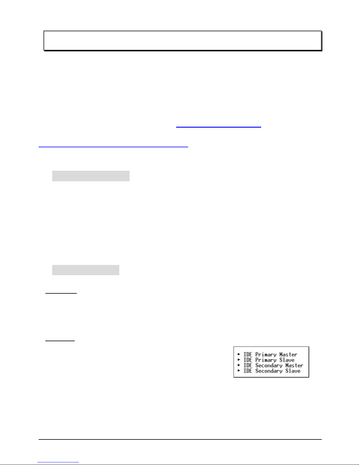
Sub-Menu
If you find a right pointer symbol appears to the left of certain
fields (as shown in the right view), that means a
sub-menu containing additional options for the field can be
launched from this field.
To enter the sub-menu, highlight the field and press <Enter>. Then you can use control keys to
move between and change the settings of the sub-menu.

EBC 340 User’s Manual 34
To return to the main menu, press <Esc> to trace back.
Status Page Setup Menu/Option Page Setup Menu
Press <F1> to pop up a small help window that describes the appropriate keys to use and the
possible selections for the highlighted item. To exit the Help Window press <Esc>.
EBC 340 User’s Manual 35
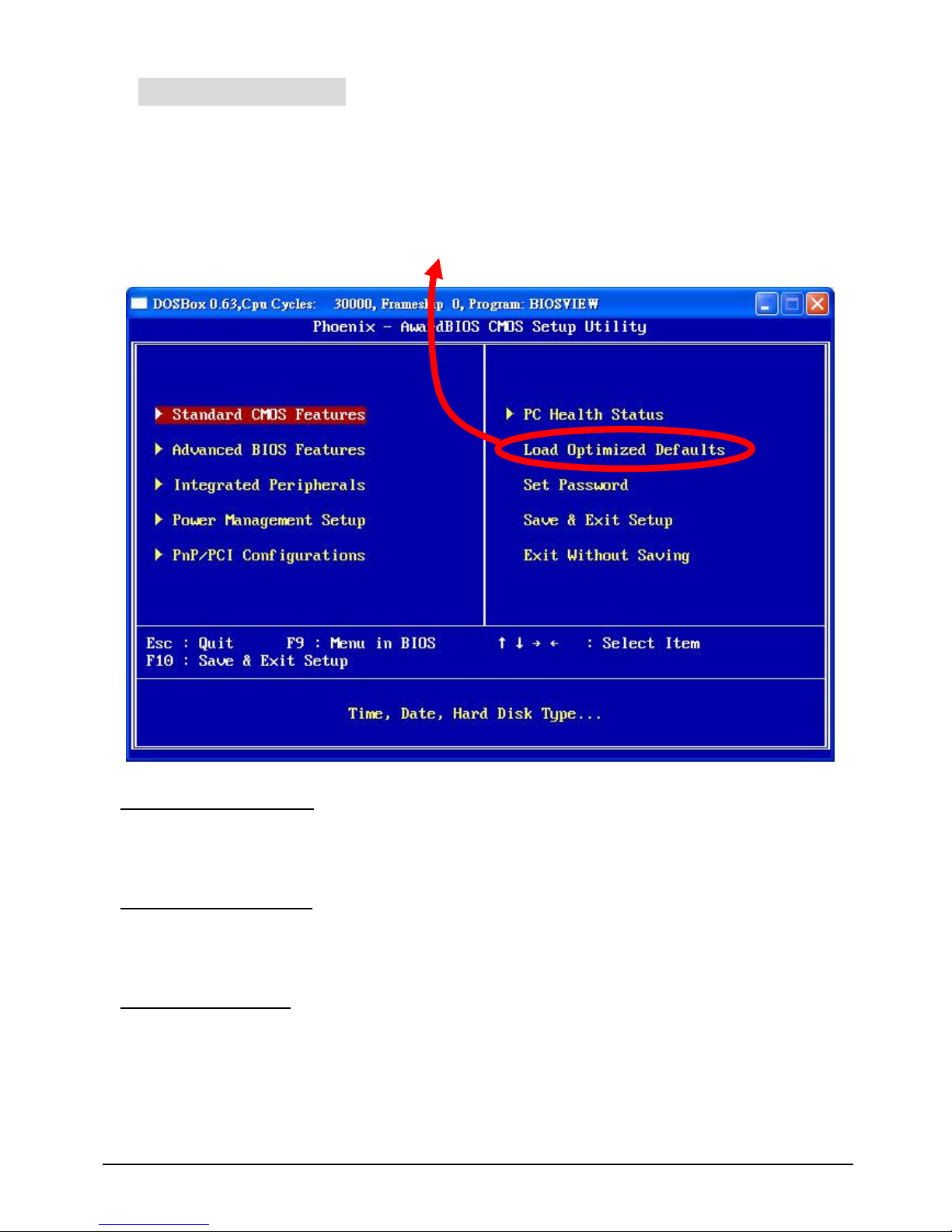
4.3 The Main Menu
Once you enter Award BIOS CMOS Setup Utility, the Main Menu (Figure 1) will appear on the
screen. The Main Menu allows you to select from ten setup functions and two exit choices.
Use arrow keys to select among the items and press <Enter> to accept or enter the
sub-menu.
It is recommended to load the Defaults for “Optimized” .
Standard CMOS Features
Use this menu for basic system configuration.
Advanced BIOS Features
Use this menu to set the Advanced Features available on your system.
Integrated Peripherals
Use this menu to specify your settings for integrated peripherals.

EBC 340 User’s Manual 36
Power Management setup
Use this menu to specify your settings for power management
PNP/PCI Configuration
This entry appears if your system supports PnP / PCI.
PC health Status
Display CPU/System Temperature, Fan speed.
Load Optimized Defaults
Use this menu to load the BIOS default values that are factory settings for optimal
Uperformance system operations. While Award has designed the custom BIOS to maximize
performance, the factory has the right to change these defaults to meet their needs.
Set Password
Enter and change the options of the setup menus. If password error or disable, some read only
INFO will be displayed on the menu.
Save & Exit Setup
Save CMOS value changes to CMOS and exit setup.
Exit Without Saving
Abandon all CMOS value changes and exit setup.
 Loading...