


NEXCOM International Co., Ltd.
Industrial Computing Solutions
Applied Panel Display
APPD 1200T/1205T/1500T/1700T/1900T
User Manual
NEXCOM International Co., Ltd.
Published May 2014
www.nexcom.com

Content
Contents
Preface
Copyright ............................................................................................. iv
Disclaimer .............................................................................................. iv
Acknowledgements ............................................................................... iv
Regulatory Compliance Statements ........................................................ iv
Declaration of Conformity ...................................................................... iv
RoHS Compliance ................................................................................... v
Warranty and RMA ................................................................................ vi
Safety Information ................................................................................viii
Installation Recommendations ...............................................................viii
Safety Precautions .................................................................................. ix
Technical Support and Assistance ............................................................ x
Conventions Used in this Manual ............................................................ x
Global Service Contact Information ........................................................ xi
Package Contents ................................................................................. xiii
Ordering Information .............................................................................xv
Chapter 1: Product Introduction
Overview - APPD 1200T/1205T ...............................................................1
Key Features ...........................................................................................1
Overview - APPD 1500T .......................................................................... 2
Key Features ...........................................................................................2
Overview - APPD 1700T .......................................................................... 3
Key Features ...........................................................................................3
Overview - APPD 1900T .......................................................................... 4
Key Features ...........................................................................................4
Specifications .......................................................................................... 5
APPD 1200T ........................................................................................ 5
Specifications .......................................................................................... 6
APPD 1205T ........................................................................................ 6
Specifications .......................................................................................... 7
APPD 1500T ........................................................................................ 7
Specifications .......................................................................................... 8
APPD 1700T ........................................................................................ 8
Specifications .......................................................................................... 9
APPD 1900T ........................................................................................ 9
Knowing Your APPD Series ...................................................................10
Front Top View of APPD 1200T/1205T ...............................................10
Front Top View of APPD 1500T ..........................................................10
Front Top View of APPD 1700T ..........................................................10
Front Top View of APPD 1900T ..........................................................10
Front Top View in Detail .....................................................................11
Rear Bottom View of APPD 1200T/1205T ..........................................12
Rear Bottom View of APPD 1500T ..................................................... 12
Rear Bottom View of APPD 1700T ..................................................... 12
Rear Bottom View of APPD 1900T ..................................................... 12
Rear Bottom View in Detail ................................................................ 13
Rear View of APPD 1200T/1205T .......................................................14
Rear View of APPD 1500T .................................................................15
Rear View of APPD 1700T .................................................................16
Rear View of APPD 1900T .................................................................17
Mechanical Dimensions .........................................................................18
APPD 1200T/1205T ...........................................................................18
Copyright © 2012 NEXCOM International Co., Ltd. All Rights Reserved.
ii
APPD 1200T/1205T/1500T/1700T/1900T User Manual

Content
APPD 1500T ...................................................................................... 19
APPD 1700T ...................................................................................... 20
APPD 1900T ...................................................................................... 21
Chapter 2: Connector Pin Definitions
External I/O Interfaces ........................................................................... 22
USB Port ............................................................................................ 22
COM Port .......................................................................................... 22
DVI Port (DVI-D) .................................................................................23
VGA Port ........................................................................................... 23
12 – 24V DC Input ............................................................................24
Chapter 3: System Setup
Panel Mounting ....................................................................................25
Installing the Power Adapter Bracket ..................................................... 28
Chapter 4: Adjusting the Display
OSD Menu Functions ............................................................................33
Chapter 5: Touch Driver Settings...........................49
Appendix A: Power Consumption.........................50
Appendix B: Extended Display Identification
Data Timing Support..............................................51
Copyright © 2012 NEXCOM International Co., Ltd. All Rights Reserved.
iii
APPD 1200T/1205T/1500T/1700T/1900T User Manual

Preface
Preface
Copyright
This publication, including all photographs, illustrations and software, is
protected under international copyright laws, with all rights reserved. No
part of this manual may be reproduced, copied, translated or transmitted in
any form or by any means without the prior written consent from NEXCOM
International Co., Ltd.
Disclaimer
The information in this document is subject to change without prior notice and
does not represent commitment from NEXCOM International Co., Ltd. However,
users may update their knowledge of any product in use by constantly checking
its manual posted on our website: http://www.nexcom.com. NEXCOM shall
not be liable for direct, indirect, special, incidental, or consequential damages
arising out of the use of any product, nor for any infringements upon the rights
of third parties, which may result from such use. Any implied warranties of
merchantability or fitness for any particular purpose is also disclaimed.
Acknowledgements
APPD 1200T/1205T/1500T/1700T/1900T is a trademark of NEXCOM
International Co., Ltd. All other product names mentioned herein are
registered trademarks of their respective owners.
Regulatory Compliance Statements
This section provides the FCC compliance statement for Class B devices and
describes how to keep the system CE compliant.
Declaration of Conformity
FCC
This equipment has been tested and verified to comply with the limits for
a Class B digital device, pursuant to Part 15 of FCC Rules. These limits are
designed to provide reasonable protection against harmful interference when
the equipment is operated in a commercial environment. This equipment
generates, uses, and can radiate radio frequency energy and, if not installed
and used in accordance with the instructions, may cause harmful interference
to radio communications. Operation of this equipment in a residential area
(domestic environment) is likely to cause harmful interference, in which
case the user will be required to correct the interference (take adequate
measures) at their own expense.
CE
The product(s) described in this manual complies with all applicable
European Union (CE) directives if it has a CE marking. For computer systems
to remain CE compliant, only CE-compliant parts may be used. Maintaining
CE compliance also requires proper cable and cabling techniques.
Copyright © 2012 NEXCOM International Co., Ltd. All Rights Reserved.
iv
APPD 1200T/1205T/1500T/1700T/1900T User Manual

Preface
RoHS Compliance
NEXCOM RoHS Environmental Policy and Status
Update
This publication, including all photographs, illustrations
and software, is protected under international copyright
laws, with all rights reserved. No part of this manual
may be reproduced, copied, translated or transmitted in any form or by any
means without the prior written consent from NEXCOM International Co.,
Ltd.
RoHS restricts the use of Lead (Pb) < 0.1% or 1,000ppm, Mercury (Hg) < 0.1%
or 1,000ppm, Cadmium (Cd) < 0.01% or 100ppm, Hexavalent Chromium
(Cr6+) < 0.1% or 1,000ppm, Polybrominated biphenyls (PBB) < 0.1% or
1,000ppm, and Polybrominated diphenyl Ethers (PBDE) < 0.1% or 1,000ppm.
In order to meet the RoHS compliant directives, NEXCOM has established
an engineering and manufacturing task force to implement the introduction
of green products. The task force will ensure that we follow the standard
NEXCOM development procedure and that all the new RoHS components
and new manufacturing processes maintain the highest industry quality
levels for which NEXCOM are renowned.
The model selection criteria will be based on market demand. Vendors and
suppliers will ensure that all designed components will be RoHS compliant.
How to recognize NEXCOM RoHS Products?
For existing products where there are non-RoHS and RoHS versions, the
suffix “(LF)” will be added to the compliant product name.
All new product models launched after January 2006 will be RoHS compliant.
They will use the usual NEXCOM naming convention.
Copyright © 2012 NEXCOM International Co., Ltd. All Rights Reserved.
v
APPD 1200T/1205T/1500T/1700T/1900T User Manual

Preface
Warranty and RMA
NEXCOM Warranty Period
NEXCOM manufactures products that are new or equivalent to new in
accordance with industry standard. NEXCOM warrants that products will
be free from defect in material and workmanship for 2 years, beginning on
the date of invoice by NEXCOM. HCP series products (Blade Server) which
are manufactured by NEXCOM are covered by a three year warranty period.
NEXCOM Return Merchandise Authorization (RMA)
▪ Customers shall enclose the “NEXCOM RMA Service Form” with the
returned packages.
▪ Customers must collect all the information about the problems
encountered and note anything abnormal or, print out any on-screen
messages, and describe the problems on the “NEXCOM RMA Service
Form” for the RMA number apply process.
▪ Customers can send back the faulty products with or without accessories
(manuals, cable, etc.) and any components from the card, such as CPU
and RAM. If the components were suspected as part of the problems,
please note clearly which components are included. Otherwise, NEXCOM
is not responsible for the devices/parts.
▪ Customers are responsible for the safe packaging of defective products,
making sure it is durable enough to be resistant against further damage
and deterioration during transportation. In case of damages occurred
during transportation, the repair is treated as “Out of Warranty.”
▪ Any products returned by NEXCOM to other locations besides the
customers’ site will bear an extra charge and will be billed to the customer.
Repair Service Charges for Out-of-Warranty Products
NEXCOM will charge for out-of-warranty products in two categories, one is
basic diagnostic fee and another is component (product) fee.
Repair Service Charges for Out-of-Warranty Products
NEXCOM will charge for out-of-warranty products in two categories, one is
basic diagnostic fee and another is component (product) fee.
System Level
▪ Component fee: NEXCOM will only charge for main components such as
SMD chip, BGA chip, etc. Passive components will be repaired for free,
ex: resistor, capacitor.
▪ Items will be replaced with NEXCOM products if the original one cannot
be repaired. Ex: motherboard, power supply, etc.
▪ Replace with 3rd party products if needed.
▪ If RMA goods can not be repaired, NEXCOM will return it to the customer
without any charge.
Board Level
▪ Component fee: NEXCOM will only charge for main components, such
as SMD chip, BGA chip, etc. Passive components will be repaired for free,
ex: resistors, capacitors.
▪ If RMA goods can not be repaired, NEXCOM will return it to the customer
without any charge.
Copyright © 2012 NEXCOM International Co., Ltd. All Rights Reserved.
vi
APPD 1200T/1205T/1500T/1700T/1900T User Manual

Preface
Warnings
Read and adhere to all warnings, cautions, and notices in this guide and
the documentation supplied with the chassis, power supply, and accessory
modules. If the instructions for the chassis and power supply are inconsistent
with these instructions or the instructions for accessory modules, contact
the supplier to find out how you can ensure that your computer meets
safety and regulatory requirements.
Cautions
Electrostatic discharge (ESD) can damage system components. Do the
described procedures only at an ESD workstation. If no such station is
available, you can provide some ESD protection by wearing an antistatic
wrist strap and attaching it to a metal part of the computer chassis.
Copyright © 2012 NEXCOM International Co., Ltd. All Rights Reserved.
vii
APPD 1200T/1205T/1500T/1700T/1900T User Manual

Preface
Safety Information
Before installing and using the device, note the following precautions:
▪ Read all instructions carefully.
▪ Do not place the unit on an unstable surface, cart, or stand.
▪ Follow all warnings and cautions in this manual.
▪ When replacing parts, ensure that your service technician uses parts
specified by the manufacturer.
▪ Avoid using the system near water, in direct sunlight, or near a heating
device.
▪ The load of the system unit does not solely rely for support from the
rackmounts located on the sides. Firm support from the bottom is highly
necessary in order to provide balance stability.
Installation Recommendations
Ensure you have a stable, clean working environment. Dust and dirt can get
into components and cause a malfunction. Use containers to keep small
components separated.
Adequate lighting and proper tools can prevent you from accidentally
damaging the internal components. Most of the procedures that follow
require only a few simple tools, including the following:
▪ A Philips screwdriver
▪ A flat-tipped screwdriver
▪ A grounding strap
▪ An anti-static pad
Using your fingers can disconnect most of the connections. It is recommended
that you do not use needle-nose pliers to disconnect connections as these
can damage the soft metal or plastic parts of the connectors.
Copyright © 2012 NEXCOM International Co., Ltd. All Rights Reserved.
viii
APPD 1200T/1205T/1500T/1700T/1900T User Manual

Preface
Safety Precautions
1. Read these safety instructions carefully.
2. Keep this User Manual for later reference.
3. Disconnect this equipment from any AC outlet before cleaning. Use a
damp cloth. Do not use liquid or spray detergents for cleaning.
4. For plug-in equipment, the power outlet socket must be located near the
equipment and must be easily accessible.
5. Keep this equipment away from humidity.
6. Put this equipment on a stable surface during installation. Dropping it or
letting it fall may cause damage.
7. The openings on the enclosure are for air convection to protect the
equipment from overheating. DO NOT COVER THE OPENINGS.
8. Make sure the voltage of the power source is correct before connecting
the equipment to the power outlet.
9. Place the power cord in a way so that people will not step on it. Do not
place anything on top of the power cord. Use a power cord that has been
approved for use with the product and that it matches the voltage and
current marked on the product’s electrical range label. The voltage and
current rating of the cord must be greater than the voltage and current
rating marked on the product.
10. All cautions and warnings on the equipment should be noted.
11. If the equipment is not used for a long time, disconnect it from the
power source to avoid damage by transient overvoltage.
12. Never pour any liquid into an opening. This may cause fire or electrical
shock.
13. Never open the equipment. For safety reasons, the equipment should be
opened only by qualified service personnel.
14. If one of the following situations arises, get the equipment checked by
service personnel:
a. The power cord or plug is damaged.
b. Liquid has penetrated into the equipment.
c. The equipment has been exposed to moisture.
d. The equipment does not work well, or you cannot get it to work
according to the user’s manual.
e. The equipment has been dropped and damaged.
f. The equipment has obvious signs of breakage.
15. Do not place heavy objects on the equipment.
16. The unit uses a three-wire ground cable which is equipped with a third
pin to ground the unit and prevent electric shock. Do not defeat the
purpose of this pin. If your outlet does not support this kind of plug,
contact your electrician to replace your obsolete outlet.
17. CAUTION: DANGER OF EXPLOSION IF BATTERY IS INCORRECTLY
REPLACED. REPLACE ONLY WITH THE SAME OR EQUIVALENT TYPE
RECOMMENDED BY THE MANUFACTURER. DISCARD USED BATTERIES
ACCORDING TO THE MANUFACTURER’S INSTRUCTIONS.
Copyright © 2012 NEXCOM International Co., Ltd. All Rights Reserved.
ix
APPD 1200T/1205T/1500T/1700T/1900T User Manual

Preface
CAUTION!
Technical Support and Assistance
1. For the most updated information of NEXCOM products, visit NEXCOM’s
website at www.nexcom.com.
2. For technical issues that require contacting our technical support team or
sales representative, please have the following information ready before
calling:
– Product name and serial number
– Detailed information of the peripheral devices
– Detailed information of the installed software (operating system,
version, application software, etc.)
– A complete description of the problem
– The exact wordings of the error messages
Warning!
1. Handling the unit: carry the unit with both hands and handle it with care.
2. Maintenance: to keep the unit clean, use only approved cleaning products
or clean with a dry cloth.
3. CompactFlash: Turn off the unit’s power before inserting or removing a
CompactFlash storage card.
Conventions Used in this Manual
Warning:
Information about certain situations, which if not observed,
can cause personal injury. This will prevent injury to yourself
when performing a task.
CAUTION!CAUTION!
Caution:
Information to avoid damaging components or losing data.
Note:
Provides additional information to complete a task easily.
Copyright © 2012 NEXCOM International Co., Ltd. All Rights Reserved.
x
APPD 1200T/1205T/1500T/1700T/1900T User Manual

Preface
Global Service Contact Information
Headquarters
NEXCOM International Co., Ltd.
15F, No. 920, Chung-Cheng Rd.,
ZhongHe District, New Taipei City, 23586,
Taiwan, R.O.C.
Tel: +886-2-8226-7786
Fax: +886-2-8226-7782
www.nexcom.com
America
USA
NEXCOM USA
2883 Bayview Drive,
Fremont CA 94538, USA
Tel: +1-510-656-2248
Fax: +1-510-656-2158
Email: sales@nexcom.com
www.nexcom.com
Asia
Taiwan
Central Taiwan Office
16F, No.250, Sec. 2, Chongde Rd.,
Beitun Dist., Taichung City 406, R.O.C.
Tel: +886-4-2249-1179
Fax: +886-4-2249-1172
Email: sales@nexcom.com.tw
www.nexcom.com.tw
Japan
NEXCOM Japan
9F, Tamachi Hara Bldg., 4-11-5, Shiba Minato-ku,
Tokyo, 108-0014, Japan
Tel: +81-3-5419-7830
Fax: +81-3-5419-7832
Email: sales@nexcom-jp.com
www.nexcom-jp.com
China
NEXCOM China
1F & 2F, Block A, No. 16 Yonyou Software Park,
No. 68 Beiqing Road, Haidian District,
Beijing, 100094, China
Tel: +86-010-5704-2680
Fax: +86-010-5704-2681
Email: sales@nexcom.cn
www.nexcom.cn
Shanghai Office
Room 603/604, Huiyinmingzun Plaza Bldg., 1,
No.609, Yunlin East Rd.,
Shanghai, 200062, China
Tel: +86-21-5278-5868
Fax: +86-21-3251-6358
Email: sales@nexcom.cn
www.nexcom.cn
Copyright © 2012 NEXCOM International Co., Ltd. All Rights Reserved.
xi
APPD 1200T/1205T/1500T/1700T/1900T User Manual

Preface
Shenzhen Office
Room1707, North Block, Pines Bldg.,
No.7 Tairan Rd., Futian Area,
Shenzhen, 518040, China
Tel: +86-755-8332-7203
Fax: +86-755-8332-7213
Email: sales@nexcom.cn
www.nexcom.cn
Wuhan Office
1-C1804/ 1805, Mingze Liwan,
No. 519 South Luoshi Rd.,
Hongshan District,
Wuhan, 430070, China
Tel: +86-27-8722-7400
Fax: +86-27-8722-7400
Email: sales@nexcom.cn
www.nexcom.cn
Chengdu Office
9F, Shuxiangxie, Xuefu Garden,
No.12 Section 1, South Yihuan Rd.,
Chengdu, 610061, China
Tel: +86-28-8523-0186
Fax: +86-28-8523-0186
Email: sales@nexcom.cn
www.nexcom.cn
Europe
Italy
NEXCOM ITALIA S.r.l
Via Gaudenzio Ferrari 29,
21047 Saronno (VA), Italia
Tel: +39 02 9628 0333
Fax: +39 02 9286 9215
Email: nexcomitalia@nexcom.eu
www.nexcomitalia.it
United Kingdom
NEXCOM EUROPE
10 Vincent Avenue,
Crownhill Business Centre,
Milton Keynes, Buckinghamshire MK8 0AB,
United Kingdom
Tel: +44-1908-267121
Fax: +44-1908-262042
Email: sales.uk@nexcom.eu
www.nexcom.eu
Copyright © 2012 NEXCOM International Co., Ltd. All Rights Reserved.
xii
APPD 1200T/1205T/1500T/1700T/1900T User Manual

Preface
Package Contents
Before continuing, verify that the package you received is complete. The APPD series package, APPD 1200T/1205T/1500T/1700T/1900T, should have all the
items listed in the table.
APPD 1200T/1205T/1500T/1700T
Item Description Qty
1 Panel Mount Kit 12
2 Driver CD 1
3 Touch Pen 1
4 VGA Cable (1.8m) 1
5 USB Cable (1.8m) 1
6 Serial Cable (1.8m) 1
7 Terminal blocks 3-pin Phoenix Contact Plug 1
8 Panel Mount Hole Block 12
Terminal blocks
3-pin Phoenix
Contact Plug
VGA Cable USB Cable
Panel Mount Kit Driver CD Touch Pen
Copyright © 2012 NEXCOM International Co., Ltd. All Rights Reserved.
xiii
Serial Cable Panel Mount Hole Block
Note: Package contents may vary depending on your country
region, some items may be optional. Please contact your local
distributor for more information.
APPD 1200T/1205T/1500T/1700T/1900T User Manual

Preface
APPD 1900T
Item Description Qty
1 Panel Mount Kit 14
2 Driver CD 1
3 Touch Pen 1
4 VGA Cable (1.8m) 1
5 USB Cable (1.8m) 1
6 Serial Cable (1.8m) 1
7 Terminal blocks 3-pin Phoenix Contact Plug 1
8 Panel Mount Hole Block 14
Terminal blocks
3-pin Phoenix
Contact Plug
VGA Cable USB Cable
Panel Mount Kit Driver CD Touch Pen
Copyright © 2012 NEXCOM International Co., Ltd. All Rights Reserved.
xiv
Serial Cable
Panel Mount Hole Block
Note: Package contents may vary depending on your country
region, some items may be optional. Please contact your local
distributor for more information.
APPD 1200T/1205T/1500T/1700T/1900T User Manual

Preface
Ordering Information
The following provides ordering information for the Applied Panel Display series.
• Barebone
APPD 1200T (P/N: 10IAD120000X0)
12.1” SVGA industrial 4:3 LED Backlight flush touch monitor with VGA, and DVI-D input, 12~24VDC input, RS-232 and USB touch screen interfaces
APPD 1205T (P/N: 10IAD120500X0)
12.1” XGA industrial 4:3 LED Backlight flush touch monitor with VGA, and DVI-D input, 12~24VDC input, RS-232 and USB touch screen interfaces
APPD 1500T (P/N: 10IAD150000X0)
15” XGA industrial 4:3 LED Backlight flush touch monitor with VGA, and DVI-D input, 12~24VDC input, RS-232 and USB touch screen interfaces
APPD 1700T (P/N: 10IAD170000X0)
17” SXGA industrial 4:3 LCD flush touch monitor with VGA and DVI-D input, 12~24VDC input, RS-232 and USB touch screen interfaces
APPD 1900T (P/N: 10IAD190000X0)
19” SXGA industrial 4:3 LED Backlight flush touch monitor with VGA, and DVI-D input, 12~24V DC input, RS-232 and USB touch screen interfaces
• Optional
12V, 60W AC/DC power adapter w/o power cord (P/N: 7400060011X00)
US Power Cord (P/N: 60233POW17X00) UK Power Cord (P/N: 60233POW19X00) EU Power Cord (P/N: 60233POW18X00) 1.8m DVI-D Cable (P/N: 60233DVI28X00)
Copyright © 2012 NEXCOM International Co., Ltd. All Rights Reserved.
xv
APPD 1200T/1205T/1500T/1700T/1900T User Manual

Chapter 1: Product Introduction
Chapter 1: Product Introduction
Overview - APPD 1200T/1205T
Key Features
▪ IP65 compliant plastic front bezel with flush panel by 5-wire touch screen
▪ Dual display input interface: analog VGA and DVI-D
▪ Shares identical appearance with APPC series
▪ Dual touch screen interface: RS232 and USB
▪ Ultra slim in depth
▪ OSD Multilanguage function
Copyright © 2012 NEXCOM International Co., Ltd. All Rights Reserved.
1
APPD 1200T/1205T/1500T/1700T/1900T User Manual

Chapter 1: Product Introduction
Overview - APPD 1500T
Key Features
▪ IP65 compliant plastic front bezel with flush panel by 5-wire touch screen
▪ Dual display input interface: analog VGA and DVI-D
▪ Shares identical appearance with APPC series
▪ Dual touch screen interface: RS232 and USB
▪ Ultra slim in depth
▪ OSD Multilanguage function
Copyright © 2012 NEXCOM International Co., Ltd. All Rights Reserved.
2
APPD 1200T/1205T/1500T/1700T/1900T User Manual

Chapter 1: Product Introduction
Overview - APPD 1700T
Key Features
▪ IP65 compliant plastic front bezel with flush panel by 5-wire touch screen
▪ Dual display input interface: analog VGA and DVI-D
▪ Shares identical appearance with APPC series
▪ Dual touch screen interface: RS232 and USB
▪ Ultra slim in depth
▪ OSD Multilanguage function
Copyright © 2012 NEXCOM International Co., Ltd. All Rights Reserved.
3
APPD 1200T/1205T/1500T/1700T/1900T User Manual

Chapter 1: Product Introduction
Overview - APPD 1900T
Key Features
▪ IP65 compliant plastic front bezel with flush panel by 5-wire touch screen
▪ Dual display input interface: analog VGA and DVI-D
▪ Shares identical appearance with APPC series
▪ Dual touch screen interface: RS232 and USB
▪ Ultra slim in depth
▪ OSD Multilanguage function
Copyright © 2012 NEXCOM International Co., Ltd. All Rights Reserved.
4
APPD 1200T/1205T/1500T/1700T/1900T User Manual

Chapter 1: Product Introduction
Specifications
APPD 1200T
Panel
▪ LED Size: 12.1”, 4:3
▪ Resolution: SVGA 800x600
▪ Luminance: 450cd/m
▪ Contrast ratio: 700
▪ LCD color: 16.2M
▪ Viewing Angle: 65(U), 75(D), 80(L), 80(R)
▪ Backlight: LED
Touch Screen
▪ 5-wire resistive (flush panel type)
▪ Light transmission: 80%
▪ Interface: USB and RS232
Rear I/O
▪ Touch screen interface port: RS-232 (1x DB9) / USB Type A
▪ Video port: VGA (1x DB15) / DVI-D (1x DVI-I connector)
▪ DC power input connector: 3-Pin Phoenix terminal Blocks
OSD Function
▪ OSD keypad
▪ Multilanguage OSD
2
▪ Power input: 12V~24VDC
▪ Power adapter: optional AC to DC power adapter (+12V, 60W)
▪ Vibration:
IEC 68 2-64
2Grms @ sine, 5~500Hz, 1hr/axis (Operating)
2.2Grms @ random condition, 5~500Hz, 0.5hr/axis (Non-operating)
▪ Shock:
IEC 68 2-27
20G@wall mount, half sine, 11ms
Operating temperature: -5°C to 60°C
Storage temperature: -20°C to 75°C
▪ Operating humidity: 10%~90% relative humidity, non-condensing
▪ Dimension: 317 x 243 x 53.5mm
▪ Weight: 2.9Kg
Certifications
▪ CE approval
▪ FCC Class B
Mechanical & Environment
▪ Color: pantone black
▪ IP protection: IP65 front
▪ Mounting: panel/ wall/ stand/ VESA 100mm x 100mm
Copyright © 2012 NEXCOM International Co., Ltd. All Rights Reserved.
5
APPD 1200T/1205T/1500T/1700T/1900T User Manual

Chapter 1: Product Introduction
Specifications
APPD 1205T
Panel
▪ LED Size: 12.1”, 4:3
▪ Resolution: XGA 1024x768
▪ Luminance: 500cd/m
▪ Contrast ratio: 700
▪ LCD color: 16.2M
▪ Viewing Angle: 80(U), 80(D), 80(L), 80(R)
▪ Backlight: LED
Touch Screen
▪ 5-wire resistive (flush panel type)
▪ Light transmission: 80%
▪ Interface: USB and RS232
Rear I/O
▪ Touch screen interface port: RS-232 (1x DB9) / USB Type A
▪ Video port: VGA (1x DB15) / DVI-D (1x DVI-I connector)
▪ DC power input connector: 3-Pin Phoenix terminal Blocks
OSD Function
▪ OSD keypad
▪ Multilanguage OSD
2
▪ Power input: 12V~24VDC
▪ Power adapter: optional AC to DC power adapter (+12V, 60W)
▪ Vibration:
IEC 68 2-64
2Grms @ sine, 5~500Hz, 1hr/axis (Operating)
2.2Grms @ random condition, 5~500Hz, 0.5hr/axis (Non-operating)
▪ Shock:
IEC 68 2-27
20G@wall mount, half sine, 11ms
Operating temperature: -5°C to 60°C
Storage temperature: -20°C to 75°C
▪ Operating humidity: 10%~90% relative humidity, non-condensing
▪ Dimension: 317 x 243 x 53.5mm
▪ Weight: 2.9Kg
Certifications
▪ CE approval
▪ FCC Class B
Mechanical & Environment
▪ Color: pantone black
▪ IP protection: IP65 front
▪ Mounting: panel/ wall/ stand/ VESA 100mm x 100mm
Copyright © 2012 NEXCOM International Co., Ltd. All Rights Reserved.
6
APPD 1200T/1205T/1500T/1700T/1900T User Manual

Chapter 1: Product Introduction
Specifications
APPD 1500T
Panel
▪ LED Size: 15”, 4:3
▪ Resolution: XGA 1024x768
▪ Luminance: 400cd/m
▪ Contrast ratio: 700
▪ LCD color: 16.2M
▪ Viewing Angle: 60(U), 80(D), 80(L), 80(R)
▪ Backlight: LED
Touch Screen
▪ 5-wire resistive (flush panel type)
▪ Light transmission: 80%
▪ Interface: USB and RS232
Rear I/O
▪ Touch screen interface port: RS-232 (1x DB9) / USB Type A
▪ Video port: VGA (1x DB15) / DVI-D (1x DVI-I connector)
▪ DC power input connector: 3-Pin Phoenix terminal Blocks
OSD Function
▪ OSD keypad
▪ Multilanguage OSD
2
▪ Power input: 12V~24VDC
▪ Power adapter: optional AC to DC power adapter (+12V, 60W)
▪ Vibration:
IEC 68 2-64
2Grms @ sine, 5~500Hz, 1hr/axis (Operating)
2.2Grms @ random condition, 5~500Hz, 0.5hr/axis (Non-operating)
▪ Shock:
IEC 68 2-27
20G@wall mount, half sine, 11ms
Operating temperature: -5°C to 60°C
Storage temperature: -20°C to 75°C
▪ Operating humidity: 10%~90% relative humidity, non-condensing
▪ Dimension: 384.37 x 310 x 51.2 mm
▪ Weight: 3.98Kg
Certifications
▪ CE approval
▪ FCC Class B
Mechanical & Environment
▪ Color: pantone black
▪ IP protection: IP65 front
▪ Mounting: panel/ wall/ stand/ VESA 100mm x 100mm
Copyright © 2012 NEXCOM International Co., Ltd. All Rights Reserved.
7
APPD 1200T/1205T/1500T/1700T/1900T User Manual

Chapter 1: Product Introduction
Specifications
APPD 1700T
Panel
▪ LED Size: 17”, 4:3
▪ Resolution: SXGA 1280x1024
▪ Luminance: 380cd/m
▪ Contrast ratio: 1000
▪ LCD color: 16.7M
▪ Viewing Angle: 80(U), 80(D), 85(L), 85(R)
▪ Backlight: CCFL
Touch Screen
▪ 5-wire resistive (flush panel type)
▪ Light transmission: 81%
▪ Interface: USB
Rear I/O
▪ Touch screen interface port: RS-232 (1x DB9) / USB Type A
▪ Video port: VGA (1x DB15) / DVI-D (1x DVI-I connector)
▪ DC power input connector: 3-Pin Phoenix terminal Blocks
OSD Function
▪ OSD keypad
▪ Multilanguage OSD
2
▪ Power input: 12V~24VDC
▪ Power adapter: optional AC to DC power adapter (+12V, 60W)
▪ Vibration:
IEC 68 2-64
2Grms @ sine, 5~500Hz, 1hr/axis (Operating)
2.2Grms @ random condition, 5~500Hz, 0.5hr/axis (Non-operating)
▪ Shock:
IEC 68 2-27
20G@wall mount, half sine, 11ms
Operating temperature: -5°C to 50°C
Storage temperature: -20°C to 75°C
▪ Operating humidity: 10%~90% relative humidity, non-condensing
▪ Dimension: 410.4 x 340.4 x 43.7 mm
▪ Weight: 5.3 Kg
Certifications
▪ CE approval
▪ FCC Class B
Mechanical & Environment
▪ Color: pantone black
▪ IP protection: IP65 front
▪ Mounting: panel/ wall/ stand/ VESA 100mm x 100mm
Copyright © 2012 NEXCOM International Co., Ltd. All Rights Reserved.
8
APPD 1200T/1205T/1500T/1700T/1900T User Manual

Chapter 1: Product Introduction
Specifications
APPD 1900T
Panel
▪ LED Size: 19”, 4:3
▪ Resolution: SXGA 1280x1024
▪ Luminance: 350cd/m
▪ Contrast ratio: 1000
▪ LCD color: 16.7M
▪ Viewing Angle: 80(U), 80(D), 85(L), 85(R)
▪ Backlight: LED
Touch Screen
▪ 5-wire resistive (flush panel type)
▪ Light transmission: 81%
▪ Interface: USB
Rear I/O
▪ Touch screen interface port: RS-232 (1x DB9) / USB Type A
▪ Video port: VGA (1x DB15) / DVI-D (1x DVI-I connector)
▪ DC power input connector: 3-Pin Phoenix terminal Blocks
OSD Function
▪ OSD keypad
▪ Multilanguage OSD
2
▪ Power input: 12V~24VDC
▪ Power adapter: optional AC to DC power adapter (+12V, 60W)
▪ Vibration:
IEC 68 2-64
2Grms @ sine, 5~500Hz, 1hr/axis (Operating)
2.2Grms @ random condition, 5~500Hz, 0.5hr/axis (Non-operating)
▪ Shock:
IEC 68 2-27
20G@wall mount, half sine, 11ms
Operating temperature: -5°C to 50°C
Storage temperature: -20°C to 75°C
▪ Operating humidity: 10%~90% relative humidity, non-condensing
▪ Dimension: 457.64 x 379.24 x 49.25 mm
▪ Weight: 5.4 Kg
Certifications
▪ CE approval
▪ FCC Class B
Mechanical & Environment
▪ Color: pantone black
▪ IP protection: IP65 front
▪ Mounting: panel/ wall/ stand/ VESA 100mm x 100mm
Copyright © 2012 NEXCOM International Co., Ltd. All Rights Reserved.
9
APPD 1200T/1205T/1500T/1700T/1900T User Manual

Chapter 1: Product Introduction
Knowing Your APPD Series
Front Top View of APPD 1200T/1205T
Power & OSD
Menu Buttons
Front Top View of APPD 1500T
Front Top View of APPD 1700T
Power & OSD
Menu Buttons
Front Top View of APPD 1900T
Copyright © 2012 NEXCOM International Co., Ltd. All Rights Reserved.
Power & OSD
Menu Buttons
10
Power & OSD
Menu Buttons
APPD 1200T/1205T/1500T/1700T/1900T User Manual

Chapter 1: Product Introduction
Front Top View in Detail
Power Switch
LED
Increase Brightness/
move down/
increase value
Decrease Brightness/
move up/
decrease value
Menu
LED
Displays the power status of the display. Green LED indicates the display is
switched on, if the display is not connected to a computer, the LED will flash red.
AUTO|EXIT
Power Switch
Press to power-on or power-off the display.
◀|▼
No OSD menu: Press to increase the brightness of the screen.
Inside OSD menu: Press to move the selection down in OSD menu.
Configuring options: Press to increase the value.
▶|▲
No OSD menu: Press to decrease the brightness of the screen.
Inside OSD menu: Press to move the selection up in OSD menu.
Configuring options: Press to decrease the value
OSD Menu
No OSD Menu: Press to load the OSD menu.
Inside OSD Menu: Press to select the highlighted option in OSD menu.
AUTO|EXIT
Press to exit the OSD menu, or return to main menu.
Copyright © 2012 NEXCOM International Co., Ltd. All Rights Reserved.
11
The OSD will exit automatically if there is no activity in 5
seconds. This timer can be adjusted in OSD menu (Default:
On, 5 seconds).
APPD 1200T/1205T/1500T/1700T/1900T User Manual

Chapter 1: Product Introduction
Rear Bottom View of APPD 1200T/1205T
Rear Bottom View of APPD 1500T
Rear Bottom View of APPD 1700T
Rear Bottom View of APPD 1900T
Copyright © 2012 NEXCOM International Co., Ltd. All Rights Reserved.
12
APPD 1200T/1205T/1500T/1700T/1900T User Manual

Chapter 1: Product Introduction
Rear Bottom View in Detail
USB COM DVI-D VGA DC Input
Touchscreen Connector (USB) (Optional)
This USB connector must be attached to the USB port of the PC. The
touchscreen cable is included in accessory box.
Touchscreen Connector (DB-9) (Optional)
This RS-232 connector must be connected to the RS-232 port of the PC.
RS-232 & USB touchscreen interface does not allow
connection into the system at the same time.
Copyright © 2012 NEXCOM International Co., Ltd. All Rights Reserved.
DVI Port (DVI-D)
Connected with a standard DVI connector through I/O port of this unit. Only
supports digital signals.
VGA Port (DB-15)
This DB-15 connector can be connected to the system.
12 – 24V DC Input
Terminal block socket used to plug a DC power cord.
13
APPD 1200T/1205T/1500T/1700T/1900T User Manual

Chapter 1: Product Introduction
Rear View of APPD 1200T/1205T
VESA Mounting Hole
VESA Mounting Hole
VESA Mounting Hole
VESA Mounting Hole
VESA Mounting Holes
These are mounting holes for VESA mount (100x100mm)
Copyright © 2012 NEXCOM International Co., Ltd. All Rights Reserved.
14
APPD 1200T/1205T/1500T/1700T/1900T User Manual

Chapter 1: Product Introduction
Rear View of APPD 1500T
VESA Mounting Hole
VESA Mounting Hole
VESA Mounting Hole
VESA Mounting Hole
VESA Mounting Holes
These are mounting holes for VESA mount (100x100mm)
Copyright © 2012 NEXCOM International Co., Ltd. All Rights Reserved.
15
APPD 1200T/1205T/1500T/1700T/1900T User Manual

Chapter 1: Product Introduction
Rear View of APPD 1700T
VESA Mounting Hole
VESA Mounting Hole
VESA Mounting Hole
VESA Mounting Hole
VESA Mounting Holes
These are mounting holes for VESA mount (100x100mm)
Copyright © 2012 NEXCOM International Co., Ltd. All Rights Reserved.
16
APPD 1200T/1205T/1500T/1700T/1900T User Manual

Chapter 1: Product Introduction
Rear View of APPD 1900T
VESA Mounting Hole
VESA Mounting Hole
VESA Mounting Hole
VESA Mounting Hole
VESA Mounting Holes
These are mounting holes for VESA mount (100x100mm)
Copyright © 2012 NEXCOM International Co., Ltd. All Rights Reserved.
17
APPD 1200T/1205T/1500T/1700T/1900T User Manual

Chapter 1: Product Introduction
Mechanical Dimensions
APPD 1200T/1205T
316.76
53.50 100.00
8.80
28.50
Copyright © 2012 NEXCOM International Co., Ltd. All Rights Reserved.
242.76
18
100.00
RS-232
DVI-D
APPD 1200T/1205T/1500T/1700T/1900T User Manual
+-
VGA
DCIN 12-24V
GND

Chapter 1: Product Introduction
8.80
APPD 1500T
51.20
384.37
7
19.20
292.20
309.95
RS-232DVI-D VGA+-GND
DCIN 12-24V
Copyright © 2012 NEXCOM International Co., Ltd. All Rights Reserved.
19
APPD 1200T/1205T/1500T/1700T/1900T User Manual

Chapter 1: Product Introduction
APPD 1700T
17.80
22.02
410.31
22.02
17.80
340.20
43.70
17.80
33.39
100.00
100.00
Copyright © 2012 NEXCOM International Co., Ltd. All Rights Reserved.
20
APPD 1200T/1205T/1500T/1700T/1900T User Manual

Chapter 1: Product Introduction
APPD 1900T
457.64
379.24
49.25
24.25
25.00
RS-232
270.50
DVI-D
175.22
+-
VGA
GND
DCIN 12-24V
Copyright © 2012 NEXCOM International Co., Ltd. All Rights Reserved.
21
APPD 1200T/1205T/1500T/1700T/1900T User Manual

Chapter 2: Connector Pin Definitions
Chapter 2: Connector Pin Definitions
External I/O Interfaces
USB Port
Connector type: USB port
Pin Definition
1 VCC5
2 DATA_N
3 DATA_P
4 GND
COM Port
Connector type: DB-9 port
1 5
6 9
Pin Definition Pin Definition
1 NC 2 RXD#: Receive Data
3 TXD: Transmit Data 4 NC
5 GND 6 NC
7 NC 8 NC
9 NC
Copyright © 2012 NEXCOM International Co., Ltd. All Rights Reserved.
22
APPD 1200T/1205T/1500T/1700T/1900T User Manual

Chapter 2: Connector Pin Definitions
DVI Port (DVI-D)
Connector type: 24-pin D-Sub, 2.0mm-M-180 (DVI)
Pin Definition Pin Definition
1 TMDS Data 2- 2 TMDS Data 2+
3 Shield 4 NC
5 NC 6 DDC clock
7 DDC data 8 Reserved
9 TMDS Data 1- 10 TMDS Data 1+
11 Shield 12 NC
13 NC 14 +5V
15 GND 16 Hot plug detect
17 TMDS data 0- 18 TMDS data 0+
19 Shield 20 NC
21 NC 22 Shield
23 TMDS clock+ 24 TMDS clock-
C1 NC C2 NC
C3 NC C4 NC
C5 NC
VGA Port
Connector type: DB-9 port, 9-pin D-Sub (COM1)
5 1
15 11
Pin Definition Pin Definition
1 RED 2 GREEN
3 BLUE 4 ID2
5 GND 6 RGND
7 GGND 8 BGND
9 KEY 10 SGND
11 ID0 12 SDA
13 HSYNC or CSYNC 14 VSYNC
15 SCL
Copyright © 2012 NEXCOM International Co., Ltd. All Rights Reserved.
23
APPD 1200T/1205T/1500T/1700T/1900T User Manual

Chapter 2: Connector Pin Definitions
12 – 24V DC Input
Connector type: 3-pin Terminal Block
1 3
Pin Definition
1 +
2 3 GND
Copyright © 2012 NEXCOM International Co., Ltd. All Rights Reserved.
24
APPD 1200T/1205T/1500T/1700T/1900T User Manual

Chapter 3: System Setup
371.00 3.00mm
Chapter 3: System Setup
Panel Mounting
1. Select a place on the panel where you will mount the Industrial Touch
Monitor.
2. Cut out a shape on the panel that corresponds to the Industrial Touch
Monitor’s rear dimensions.
The thickness of the panel (e.g. steel board, plank, acrylic board, wall,
etc.) where you will mount the Industrial Touch Monitor must not exceed
3mm for APPD 1500T/1900T and 4mm for APPD 1200T/1205T/1700T. If
the distance between the front bezel and panel mount hole is too wide,
it will not fit the panel mount kit.
304.50 4.00mm
230.00
APPD 1200T/1205T
297.00
Copyright © 2012 NEXCOM International Co., Ltd. All Rights Reserved.
25
APPD 1500T
APPD 1200T/1205T/1500T/1700T/1900T User Manual

Chapter 3: System Setup
CAUTION!
436.00
3.00mm
329.00
366.00
399.00 4.00mm
APPD 1700T
3. Slide the Industrial Touch Monitor through the hole until it is properly
fitted against the panel.
4. Position the mounting clamps along the rear edges of the Industrial Touch
Monitor. The first and second clamps must be positioned and secured
diagonally prior to mounting the rest of the clamps. Tighten the clamp’s
screw until it touches the panel.
CAUTION!CAUTION!
Clamp
Do not overtighten the screws to prevent damaging the
Panel PC.
Panel
APPD 1900T
Copyright © 2012 NEXCOM International Co., Ltd. All Rights Reserved.
26
APPD 1200T/1205T/1500T/1700T/1900T User Manual

Chapter 3: System Setup
5. The illustration below shows all clamps properly mounted.
Copyright © 2012 NEXCOM International Co., Ltd. All Rights Reserved.
27
APPD 1200T/1205T/1500T/1700T/1900T User Manual

Chapter 3: System Setup
Installing the Power Adapter Bracket
(Optional accessory for APPD 1900T only)
1. Locate the mounting screws for the bracket on the back side of the
chassis.
2. Remove the mounting screws and store them in a safe place for later
use.
Copyright © 2012 NEXCOM International Co., Ltd. All Rights Reserved.
28
APPD 1200T/1205T/1500T/1700T/1900T User Manual

Chapter 3: System Setup
3. Wire the power adapter cabling into the cable opening on the bracket,
then place the adapter inside the bracket.
Cable opening Power adapter cable
Copyright © 2012 NEXCOM International Co., Ltd. All Rights Reserved.
29
APPD 1200T/1205T/1500T/1700T/1900T User Manual

Chapter 3: System Setup
4. Turn the bracket over to the back side, and place the cable tie into the
two tie mounts.
Tie mount Cable tie
5. Wrap the power adapter cable, then secure the cable firmly by tying the
cable tie.
Copyright © 2012 NEXCOM International Co., Ltd. All Rights Reserved.
30
APPD 1200T/1205T/1500T/1700T/1900T User Manual

Chapter 3: System Setup
6. With the bracket still facing backwards, align the mounting holes on the
bracket to the mounting holes on the back of the chassis, then tighten
screws to secure it.
7. Plug the 3-pin terminal block connector into the DC input.
Copyright © 2012 NEXCOM International Co., Ltd. All Rights Reserved.
31
APPD 1200T/1205T/1500T/1700T/1900T User Manual

Chapter 3: System Setup
CAUTION!
8. Plug the positive, negative and GND wires of the DC power cable into
the corresponding pins on the DC input, then tighten the screws on the
terminal blocks to secure the wires.
9. Plug the AC power cord into the power adapter.
AC power cord
Before plugging the DC power cable wires into the DC input, use
CAUTION!CAUTION!
a multimeter or voltmeter to measure which wire is positive “+”,
negative “-” and GND, and ensure that they are connected to
the correct pins.
Copyright © 2012 NEXCOM International Co., Ltd. All Rights Reserved.
32
APPD 1200T/1205T/1500T/1700T/1900T User Manual

Chapter 4: Adjusting the Display
Chapter 4: Adjusting the Display
OSD Menu Functions
The On Screen Display (OSD) menu provides options to adjust the display.
Press the MENU button on the back of the display panel to open the OSD
menu. Refer to the images below for each OSD menu options.
1. Colour
1024x768 59 . 9 Hz
Contrast
Brightness
Colour Temp 9300K 6500K User
Colour Adjust
Exit
50 -
100 -
+
+
OSD
ther
EXIT
Colour
Picture
Function
OSD Menu
Misc
Exit
Contrast
→ colour → → contrast → → to increase the contrast.
→ colour → → contrast → → to decrease the
1024x768 59 . 9 Hz
Contrast
Brightness
Colour Temp 9300K 6500K User
Colour Adjust
Exit
58 -
100 -
+
+
OSD
ther
EXIT
Colour
Picture
Function
OSD Menu
Misc
Exit
Copyright © 2012 NEXCOM International Co., Ltd. All Rights Reserved.
33
APPD 1200T/1205T/1500T/1700T/1900T User Manual

Chapter 4: Adjusting the Display
Brightness
→ colour → → Brightness → → to increase the brightness.
→ colour → → Brightness → → to decrease the brightness.
1024x768 59 . 9 Hz
Contrast
Brightness
50 -
100 -
Colour Temp 9300K 6500K User
Colour Adjust
Exit
+
+
OSD
ther
EXIT
Colour
Picture
Function
OSD Menu
Misc
Exit
Colour Temp
→ colour → → contrast → →colour temp → → to
move it towards left.
→ colour → → contrast → →colour temp → → to
move it towards right.
1024x768 59 . 9 Hz
Contrast
Brightness
0 -
100 -
Colour Temp 9300K 6500K User
Colour Adjust
Exit
+
+
OSD
ther
EXIT
Colour
Picture
Function
OSD Menu
Misc
Exit
Copyright © 2012 NEXCOM International Co., Ltd. All Rights Reserved.
34
APPD 1200T/1205T/1500T/1700T/1900T User Manual

Chapter 4: Adjusting the Display
Colour Adjust
→ colour → → red → → increase the value.
→ colour → → red → → decrease the value.
1024x768 75 . 4 Hz
Red
Green
Blue
Exit
100 -
100 -
100 -
OSD
ther
EXIT
Colour
Picture
Function
OSD Menu
Misc
Exit
Exit
Exits the Colour Adjust sub-menu or press the button to exit.
1024x768 75 . 4 Hz
Colour
Picture
+
+
OSD
ther
EXIT
Function
OSD Menu
Misc
Exit
Red
Green
Blue
Exit
100 -
100 -
100 -
+
+
Copyright © 2012 NEXCOM International Co., Ltd. All Rights Reserved.
35
APPD 1200T/1205T/1500T/1700T/1900T User Manual

Chapter 4: Adjusting the Display
Exit
Exits the Colour sub-menu and return to main menu, or press the
button continuously till exit.
1024x768 59 . 9 Hz
OSD
ther
EXIT
Colour
Picture
Function
OSD Menu
Misc
Exit
Contrast
Brightness
50 -
100 -
Colour Temp 9300K 6500K User
Colour Adjust
Exit
+
+
Copyright © 2012 NEXCOM International Co., Ltd. All Rights Reserved.
36
APPD 1200T/1205T/1500T/1700T/1900T User Manual

Chapter 4: Adjusting the Display
2. Picture
Colour
Picture
Function
OSD
OSD Menu
ther
Misc
EXIT
Exit
H . Position
V . Position
Clock
Sharpness
Exit
1024x768 59 . 9 Hz
50 -
50 -
50 -
1 2 3 4 5
H. Position
→ colour → → picture → →H.position → → to move
+
+
+
the screen towards right.
→ colour → → picture → →H.position → → to move
the screen towards left.
1024x768 59 . 9 Hz
H . Position
V . Position
Clock
Sharpness
Exit
50 -
50 -
50 -
1 2 3 4 5
+
+
+
OSD
ther
EXIT
Colour
Picture
Function
OSD Menu
Misc
Exit
Copyright © 2012 NEXCOM International Co., Ltd. All Rights Reserved.
37
APPD 1200T/1205T/1500T/1700T/1900T User Manual

Chapter 4: Adjusting the Display
V. Position
→ colour → → picture → →V.position → → to move
the screen down.
→ colour → → picture → →V.position → → to move
the screen up.
1024x768 59 . 9 Hz
H . Position
V . Position
Clock
Sharpness
Exit
50 -
50 -
50 -
1 2 3 4 5
+
+
+
OSD
ther
EXIT
Colour
Picture
Function
OSD Menu
Misc
Exit
Clock
→ colour → → picture → →Clock → → stretch the
screen towards right.
→ colour → → picture → →Clock → → stretch the
screen towards right.
1024x768 59 . 9 Hz
H . Position
V . Position
Clock
Sharpness
Exit
50 -
50 -
50 -
1 2 3 4 5
+
+
+
OSD
ther
EXIT
Colour
Picture
Function
OSD Menu
Misc
Exit
Copyright © 2012 NEXCOM International Co., Ltd. All Rights Reserved.
38
APPD 1200T/1205T/1500T/1700T/1900T User Manual

Chapter 4: Adjusting the Display
Sharpness
→ colour → → picture → → →sharpness → →
to decrease it.
→ colour → → picture → → →sharpness → →
to decrease it.
1024x768 59 . 9 Hz
Colour
Picture
Function
OSD
OSD Menu
ther
Misc
EXIT
Exit
Copyright © 2012 NEXCOM International Co., Ltd. All Rights Reserved.
H . Position
V . Position
Clock
Sharpness
Exit
50 -
50 -
50 -
1 2 3 4 5
+
+
+
39
APPD 1200T/1205T/1500T/1700T/1900T User Manual
Chapter 4: Adjusting the Display
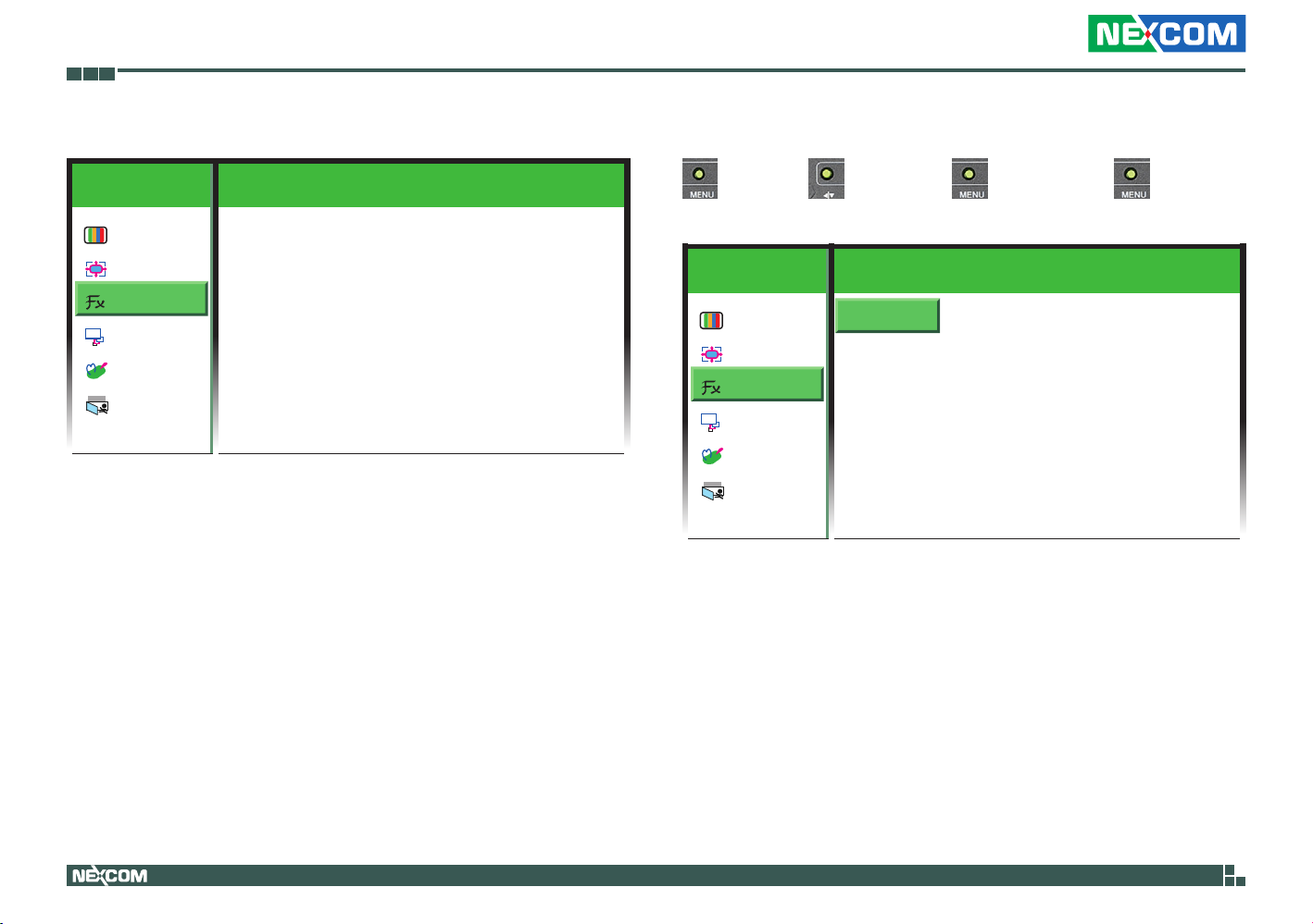
3. Function
Colour
Picture
Function
OSD
OSD Menu
ther
Misc
EXIT
Exit
1024x768 59 . 9 Hz
Auto Adjust YES NO
Exit
Auto Adjust
→ colour → → function → →auto adjust → → YES to
automatically adjust the screen size, or NO to abort it.
1024x768 59 . 9 Hz
Auto Adjust YES NO
Exit
OSD
ther
EXIT
Colour
Picture
Function
OSD Menu
Misc
Exit
Copyright © 2012 NEXCOM International Co., Ltd. All Rights Reserved.
40
APPD 1200T/1205T/1500T/1700T/1900T User Manual

Chapter 4: Adjusting the Display
Exit
Exits the Function Adjust sub-menu or press the button to exit.
→colour→ →function→ →exit.
1024x768 59 . 9 Hz
OSD
ther
EXIT
Colour
Picture
Function
OSD Menu
Misc
Exit
Auto Adjust YES NO
Auto Colour YES NO
Exit
Copyright © 2012 NEXCOM International Co., Ltd. All Rights Reserved.
41
APPD 1200T/1205T/1500T/1700T/1900T User Manual

Chapter 4: Adjusting the Display
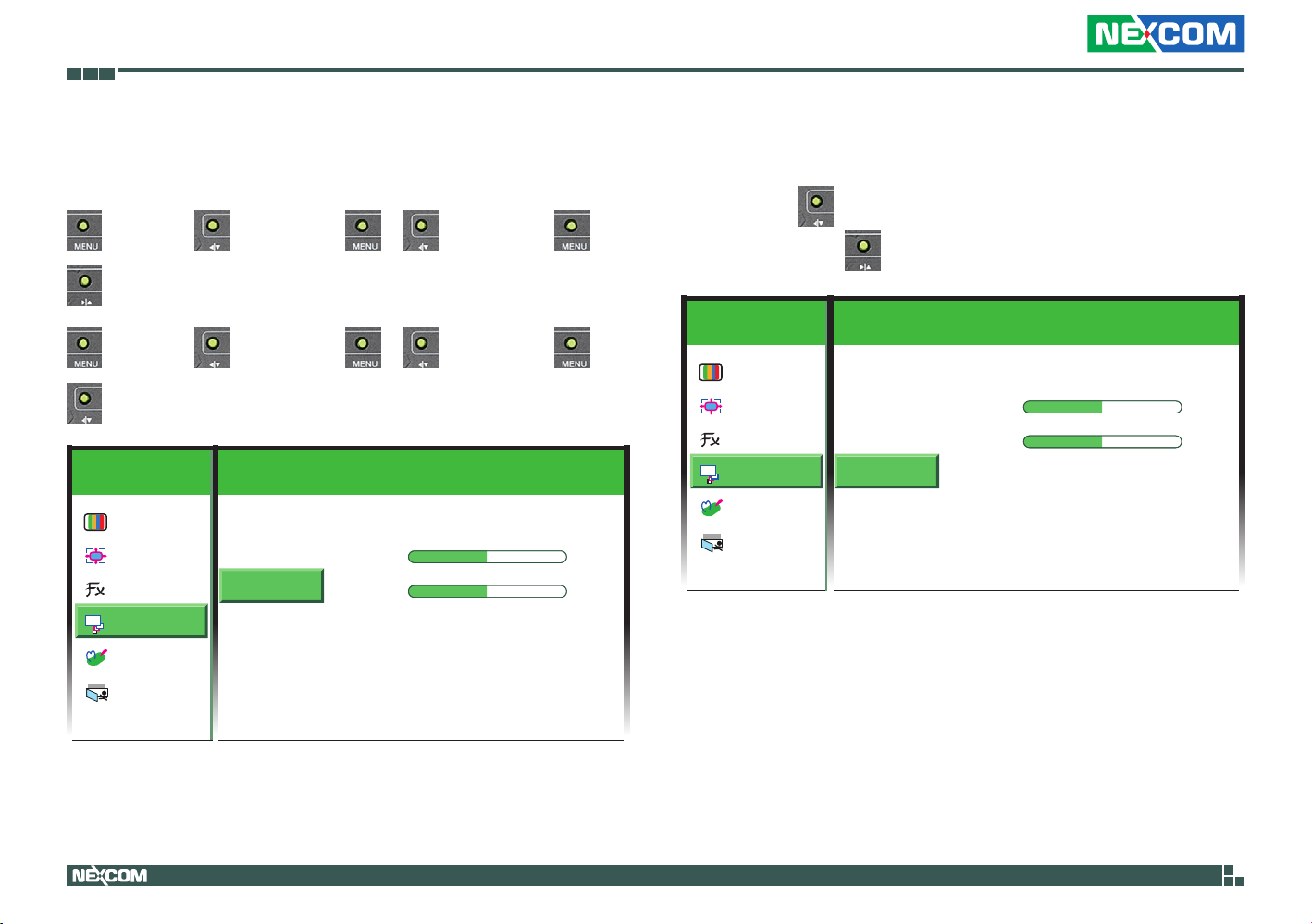
4. OSD Menu
Colour
Picture
Function
OSD
OSD Menu
ther
Misc
EXIT
Exit
1024x768 59 . 9 Hz
Language
OSD H.Pos
OSD V.Pos
OSD Timer ON OFF
Exit
0 -
50 -
Language
Press the button to enter the Language sub-menu.
1024x768 59 . 9 Hz
+
+
Colour
Picture
Function
OSD
OSD Menu
ther
Misc
EXIT
Exit
Language
OSD H.Pos
OSD V.Pos
50 -
50 -
OSD Timer ON OFF
Exit
+
+
Copyright © 2012 NEXCOM International Co., Ltd. All Rights Reserved.
42
APPD 1200T/1205T/1500T/1700T/1900T User Manual

Chapter 4: Adjusting the Display
Select the desired language for the OSD menu and press the button to
apply the language.
1024x768 59 . 9 Hz
OSD
ther
EXIT
Colour
Picture
Function
OSD Menu
Misc
Exit
English
Deutsch
한국의
繁體中文
日本语
Francais
Español
Italiano
简体中文
Português
OSD H. Pos
→ colour → → osd menu → → →osd H.pos → →
→move it towards left.
→ colour → → osd menu → → →osd H.pos → →
→move it towards right.
1024x768 59 . 9 Hz
Language
OSD H.Pos
OSD V.Pos
50 -
50 -
OSD Timer ON OFF
Exit
+
+
OSD
ther
EXIT
Colour
Picture
Function
OSD Menu
Misc
Exit
Copyright © 2012 NEXCOM International Co., Ltd. All Rights Reserved.
43
APPD 1200T/1205T/1500T/1700T/1900T User Manual
Chapter 4: Adjusting the Display
OSD V. Pos
Press ◀|▼ on the back of the display panel to move the OSD menu up, or
▶|▲ to move it down.
→ colour → → osd menu → → →osd V.pos → →
→move it down.
→ colour → → osd menu → → →osd V.pos → →
→move it up.
1024x768 59 . 9 Hz
Language
OSD H.Pos
OSD V.Pos
50 -
50 -
OSD Timer ON OFF
Exit
+
+
OSD
ther
EXIT
Colour
Picture
Function
OSD Menu
Misc
Exit
OSD Timer
Select ON to specify the timeout period of the OSD menu, or OFF to
disable it. Press on the back of the display panel to increment the
timer by 1 second, or to decrement the timer by 1 second.
1024x768 59 . 9 Hz
Language
OSD H.Pos
OSD V.Pos
50 -
50 -
OSD Timer ON OFF
Exit
+
+
OSD
ther
EXIT
Colour
Picture
Function
OSD Menu
Misc
Exit
Copyright © 2012 NEXCOM International Co., Ltd. All Rights Reserved.
44
APPD 1200T/1205T/1500T/1700T/1900T User Manual

Chapter 4: Adjusting the Display
Exit
Exits the OSD Menu sub-menu or press the button to exit.
1024x768 59 . 9 Hz
OSD
ther
EXIT
Colour
Picture
Function
OSD Menu
Misc
Exit
Language
OSD H.Pos
OSD V.Pos
50 -
50 -
OSD Timer ON OFF
Exit
+
+
Copyright © 2012 NEXCOM International Co., Ltd. All Rights Reserved.
45
APPD 1200T/1205T/1500T/1700T/1900T User Manual

Chapter 4: Adjusting the Display
5. Misc
Colour
Picture
Function
OSD
OSD Menu
ther
Misc
EXIT
Exit
1024x768 59 . 9 Hz
Reset YES NO
Volume
Input VGA DVI
Exit
Reset
→ colour → → Misc → →reset → → YES to restore
factory default settings, or NOT to abort it.
1024x768 59 . 9 Hz
Reset YES NO
Volume
Input VGA DVI
Exit
OSD
ther
EXIT
Colour
Picture
Function
OSD Menu
Misc
Exit
Copyright © 2012 NEXCOM International Co., Ltd. All Rights Reserved.
46
APPD 1200T/1205T/1500T/1700T/1900T User Manual

Chapter 4: Adjusting the Display
Input
→ colour → → Misc → → →Input → → Select
VGA or DVI as the video input.
1024x768 59 . 9 Hz
Reset YES NO
Volume
Input VGA DVI
Exit
OSD
ther
EXIT
Colour
Picture
Function
OSD Menu
Misc
Exit
Exit
Exits the Misc sub-menu or press the button to exit.
1024x768 59 . 9 Hz
Reset YES NO
Volume
Input VGA DVI
Exit
OSD
ther
EXIT
Colour
Picture
Function
OSD Menu
Misc
Exit
Copyright © 2012 NEXCOM International Co., Ltd. All Rights Reserved.
47
APPD 1200T/1205T/1500T/1700T/1900T User Manual

Chapter 4: Adjusting the Display
6. Exit
Exits the OSD main menu or press the button to exit.
1024x768 59 . 9 Hz
OSD
ther
EXIT
Colour
Picture
Function
OSD Menu
Misc
Exit
Reset YES NO
Volume
Input VGA DVI
Exit
Copyright © 2012 NEXCOM International Co., Ltd. All Rights Reserved.
48
APPD 1200T/1205T/1500T/1700T/1900T User Manual

Chapter 5: Touch Driver Settings
Chapter 5: Touch Driver Settings
Before installing the touch drivers, please adjust the Install.ini file. The Install.
ini file is located under the following folder:
\PenMount Windows Universal Driver V2.2.0.283( Win7_32_64bit_WHQL)\
Driver
1. Open the Install.ini file.
2. Confirm if the Install.ini file has the following settings, if not, please
change it.
[Install]
USB = 1 Must set this to “1”
COM = 1 Must set this to “1”
MMonitor = 1
ENUM = 1
[Option]
TouchReport = 2 USB/COM
EdgeOffset = 5
Smoothing = 1
[ENUM]
Total = 4
COM1 = 1 Set “1” to the COM port you intend to use
COM2 = 0
COM3 = 0
COM4 = 0
[COM1]
AlwaysExist
3. Install the touch drivers.
Copyright © 2012 NEXCOM International Co., Ltd. All Rights Reserved.
49
APPD 1200T/1205T/1500T/1700T/1900T User Manual

Appendix A: Power Consumption
Appendix A: Power Consumption
Purpose
The purpose of the power consumption test is verified the power
dissipation of the system and the load of the power supply.
Test Equipment
PROVA CM-07 AC/DC CLAMP METER
Desktop PC
Device Under Test
DUT: Sys #1
Test Procedure
1. Power up the DUT and then switch on the desktop PC connecting to it.
2. Measure the power consumption and record it.
3. Enter the standby mode (Turn off display).
4. Measure the power consumption and record it.
APPD 1200T
+12V +24V
Full-Loading Mode 0.73A 0.39A
Total 8.76W 9.36W
Standby Mode 0.05A 0.06A
Total 0.6W 1.44W
APPD 1205T
+12V +24V
Full-Loading Mode 0.75A 0.39A
Total 9W 9.36W
Standby Mode 0.05A 0.05A
Total 0.6W 1.2W
APPD 1500T
+12V +24V
Full-Loading Mode 0.97A 0.5A
Total 11.64W 12W
Standby Mode 0.04A 0.05A
Total 0.48W 1.2W
APPD 1700T
+12V +24V
Full-Loading Mode 2.6A 1.21A
Total 31.2W 29.04W
Standby Mode 0.05A 0.05A
Total 0.6W 1.2W
APPD 1900T
+12V +24V
Full-Loading Mode 1.54A 0.77A
Total 18.48W 18.48W
Standby Mode 0.05A 0.05A
Total 0.6W 1.2W
Copyright © 2012 NEXCOM International Co., Ltd. All Rights Reserved.
50
APPD 1200T/1205T/1500T/1700T/1900T User Manual

Appendix B: Extended Display Identification Data Timing Support
Appendix B: Extended Display Identification Data Timing Support
APPD 1200T
Resolution
APPD 1205T
Resolution
1024x768
640x480
720x400
800x600
640x480
720x400
800x600
60Hz 70Hz 72Hz 75Hz
60Hz 70Hz 72Hz 75Hz
Vertical Frequencies
Vertical Frequencies
APPD 1500T
Resolution
640x480
720x400
800x600
1024x768
Copyright © 2012 NEXCOM International Co., Ltd. All Rights Reserved.
Vertical Frequencies
60Hz 70Hz 72Hz 75Hz
51
APPD 1200T/1205T/1500T/1700T/1900T User Manual

Appendix B: Extended Display Identification Data Timing Support
APPD 1700T
Resolution
640x480
60Hz 70Hz 72Hz 75Hz
720x400
800x600
1024x768
1280x1024
APPD 1900T
Resolution
640x480
60Hz 70Hz 72Hz 75Hz
720x400
800x600
1024x768
1280x1024
Vertical Frequencies
Vertical Frequencies
Copyright © 2012 NEXCOM International Co., Ltd. All Rights Reserved.
52
APPD 1200T/1205T/1500T/1700T/1900T User Manual
 Loading...