


MZ19H
REPAIR
MANUAL
87045364 2/04

MZ19H REPAIR MANUAL CONTENTS
SECTION 1 - GENERAL INFORMATION
SECTION 2 - MODEL/SERIAL NUMBER LOCATION
SECTION 3 - GREASING AND LUBRICATION
SECTION 4 - ENGINE
SECTION 5 - TRANSAXLE
SECTION 6 - CHASSIS
SECTION 7 - MOWER DECKS
SECTION 8 - ELECTRICAL SYSTEM
The sections used through out all New Holland product Repair manuals may not be used for each
product. Each Repair manual will be made up of one or several books. Each book will be labeled as
to which sections are in the overall Repair manual and which sections are in the each book.
The sections listed above are the sections utilized for the MZ19H series tractors.

SECTION 1 - GENERAL INFORMATION
SECTION 1 - GENERAL INFORMATION
CONTENTS
Section Description Page
General Information ................................................................................................... 1-2
Think Safety First....................................................................................................... 1-2
Engine Specifications - (MZ19H)............................................................................... 1-3
Bolt Torques............................................................................................................... 1-7
Maintenance Schedule - (MZ19H)............................................................................. 1-8
1-1

SECTION 1 - GENERAL INFORMATION
This symbol means WARNING or PERSONAL SAFETY INSTRUCTION - read the
instruction because it has to do with your safety. Failure to comply with the instruction may
result in personal injury or even death
This manual is intended as a service and repair manual only. The safety instructions provided herein are for
troubleshooting, service, and repair of the MZ19H zero radius tractor. The MZ19H zero radius
attachment operator's manuals contain safety information and operating tips for safe operating practices.
Operator's manuals are available through your New Holland dealer
.
tractor and
THINK SAFETY FIRST
AVOID UNEXPECTED STARTING OF ENGINE...
Always turn off the engine and disconnect the spark
plug wire(s) before cleaning, adjusting, or repair.
AVOID LACERATIONS AND AMPUTATIONS...
Stay clear of all moving parts whenever the engine
is running. Treat all normally moving parts as if they
were moving whenever the engine is running or
has the potential to start.
AVOID BURNS...
Do not touch the engine, muffler, or other
components which may increase in temperature
during operation, while the unit is running or shortly
after it has been running.
AVOID FIRES AND EXPLOSIONS...
AVOID INJURY FROM BATTERIES...
Battery acid is poisonous and can cause burns.
Avoid contact with skin, eyes, and clothing. Battery
gases can explode. Keep cigarettes, sparks, and
flames away from the battery.
AVOID INJURY DUE TO INFERIOR PARTS...
Use only original equipment parts to ensure that
important safety criteria are met.
AVOID INJURY TO BYSTANDERS...
Always clear the area of bystanders before starting
or testing powered equipment.
AVOID INJURY DUE TO PROJECTILES...
Always clear the area of sticks, rocks, or any other
debris that could be picked up and thrown by the
powered equipment.
Avoid spilling fuel and never smoke while working
with any type of fuel or lubricant. Wipe up any
spilled fuel or oil immediately. Never remove the fuel
cap or add fuel when the engine is running. Always
use approved, labeled containers for storing or
transporting fuel and lubricants.
AVOID ASPHYXIATION...
Never operate an engine in a confined area without
proper ventilation.
AVOID MODIFICATIONS...
Never alter or modify any part unless it is a factory
approved procedure.
AVOID UNSAFE OPERATION...
Always test the safety interlock system after
making adjustments or repairs on the machine.
Refer to the Electrical section in this manual for
more information.
1-2

SECTION 1 - GENERAL INFORMATION
SPECIFICATIONS
MZ19H
ENGINE
Type............................................................... Kawasaki
Model............................................................. FH580V
Horsepower ................................................... 14.2 kw (19)@3600 RPM
Cylinders........................................................ V-Twin
Displacement................................................. 585CC (35.7 cu. in.)
Low Idle Speed.............................................. 1400 RPM
Maximum Speed:
High Idle .................................................... 3400 RPM
Oil Capacity ................................................... 1.9 qt. (1.8L)
Spec Number................................................. AS13
Fuel Unleaded Gasoline ................................ 87 octane min.
Vertical Shaft ................................................. 1 in. (2.54 cm) Dia
Charge coil .................................................... 12v - 13 amp
Other.............................................................. Air cooled, Dual element air cleaner, Fuel pump,
Overhead valve, Four cycle, Electronic ignition, Full
pressure lubricated with oil filter
CONSTRUCTION
Front Frame................................................... Welded 1 x 2 x .120 structural steel tube
Rear Frame ................................................... Welded, 7 and 10 ga. high strength steel
Frame Assembly............................................ Front and rear frames bolted together
FUEL SYSTEM
Capacity......................................................... 5 Gallon (18.9 L)
Type............................................................... Single fuel tank fender mounting on left side
Other.............................................................. Fuel tank shut-off, Fuel filter (replaceable in-line type),
Large diameter vented fuel cap, Tank includes molded
beverage holder
TRACTION SYSTEM
Transaxles ..................................................... Twin Hydro-Gear Hydrostatic Transaxles
Transaxle Drive ............................................. Belt drive with self-tensioning system
Ground speed................................................ Infinite, 0 to 7-MPH (10.5-km/hr) forward, 0 to 3.4-MPH
(5.5-km/hr) reverse
Transport Rods.............................................. Allow unit to be moved without engine running
ATTACHMENT DRIVE
Clutch ............................................................ Electric Clutch
Type............................................................... Vertical drive with single deep B-groove Pulley
1-3

SECTION 1 - GENERAL INFORMATION
MZ19H
TIRES
Rear Drive Tires ............................................ 18 x 10.5-10 4 ply with “Multitrac CS” tread
Front Castor Tires.......................................... 410/350 x 4 with “sawtooth” tread
Tire Pressure ................................................. 13 psi (90 kPa), rear, 35 psi (241 kPa) front
OPERATORS SEAT
Type............................................................... High back foam padded with arm rests
Mounting........................................................ Hinged mounting for easy access to battery and controls;
spring suspension
Adjustment..................................................... Fore and aft 3 in. (76 mm) by loosening 2 knobs and
sliding seat
STEERING
Levers............................................................ Dual wrap-around levers control hydraulic pumps
Dampening .................................................... Dual hydraulic dampers
Turning Radius .............................................. Zero radius turn (ZRT)
CONTROLS
Steering Lever ............................................... Dual wrap-around with cushioned grips
Parking Brake ................................................ Left hand operated lever with cushioned grip
Attachment Lift............................................... Right hand operated lever with cushioned grip
Cutting Height................................................ Rightside incorporated with attachment lift
Engine Throttle .............................................. Rightside console mounted lever
Ignition Switch ............................................... Rightside console mounted electric with key
Power Take Off .............................................. Rightside console mounted electric
INTERLOCKS
Seat ............................................................... Operator presence switch
Control Lever ................................................. Dual neutral sensing switch
Power Take Off .............................................. Position switch
Brake ............................................................. Position switch
ELECTRICAL SYSTEM
Battery Voltage .............................................. 12 volt negative ground
Battery Type .................................................. BCI Group U1
Fused............................................................. (1) 30 amp blade type, main
(1) 25 amp blade type, charge system
(1) 10 amp (blade type) included with optional light kit
1-4

SECTION 1 - GENERAL INFORMATION
MZ19H
LUBRICATION FITTINGS
Front Castor Pivots........................................ 2 Fittings
Front Castor Wheels...................................... 2 Fittings
Lift Assembly ................................................. 3 Fittings
Deck Idler Pivot ............................................. 1 Fitting
Transaxle Idler Pivot...................................... 1 Fitting
Control Linkage Pivot .................................... 2 Fittings
DIMENSIONS
Wheel Base ................................................... 52.1 in. (132.3 cm) center of castor to center of drive tires
Width ............................................................. 47.6 in. (120.9 cm) outside rear tires
Overall Width ................................................. 65 in. (165.1 cm) with deck deflector down
58 in. (147.3 cm) Gate width with deck deflector up.
Overall Length ............................................... 77.5 in. (196.9 cm)
Overall Height................................................ 41 in. (104.1 cm)
Track Width ................................................... 37.5 in. (95.3 cm) center to center of rear tires
30.4 in. (77.2 cm) center to center of castor tires
Deck Width .................................................... 65 in. (165.1 cm) w/deflector down
WEIGHT
Net Weight 680 lbs. (309 kg) (estimated)
DECK Right side discharge. 52 in. (132 cm) cut, three blade
mid-mounted rotary. Drawn 12 gauge steel deck with
welded mounting brackets and gauge wheel brackets.
Frame supported.
DECK BELT COVERS Removable 16 gauge formed sheet metal, fastened to
deck with thread forming screws. Access holes in top for
greasing spindles.
DEFLECTOR 12 gauge formed, held down by torsion springs at pivot
bracket.
ANTI-SCALP ROLLERS One front mounted
DECK OFFSET None. Deck centerline on machine centerline.
1-5

SECTION 1 - GENERAL INFORMATION
MZ19H
GAUGE WHEELS One on each front corner, one on each rear corner to
reduce scalping. Gauge wheels have four height position
adjustments.
HEIGHT OF CUT Adjusts from 1.5” to 4.5” (38 to 114 mm) (7 positions)
UNCUT CIRCLE 0” uncut circle
ENGINE TO DECK DRIVE HB-section Kevlar cord “V” belt from engine clutch
sheave to deck spindle sheaves. Spring loaded idler for
belt tension and take-up
SPINDLE ASSEMBLIES Three 17-mm diameter spindles turning in permanently
lubed ball bearings. Die cast aluminum spindle housings.
BLADES Three 18” x 2.5” x .187” heat treated steel blades
TIP SPEED 17,500 ft/min (5334 m/min) @ 3400 RPM nominal
18,070 ft/min (5507 m/min) @ 3500 RPM max
DECK MOUNTING Deck suspended from front frame by four trunnion rods
and attached to lift mechanism by two multi-position links
(“pork chops”).
OPTIONAL EQUIPMENT
Recycler Kit
Light Kit
Snow Plow Attachment
Tire Chains
Smooth Castor Wheel Kit
Striping Kit
Decal Kit - Canada
CERTIFICATION Conforms to California CARB and EPA Certification.
Conforms to ANSI B71.1-2001
1-6

SECTION 1 - GENERAL INFORMATION
BOLT TORQUES
DESCRIPTION TORQUE
Blade to Spindle 80 - 100 ft lb (109 - 136 N·m)
Caster Bolts 77 - 95 ft lb (105 - 130 N·m)
Clutch Bolt 50 - 60 ft lb (68 - 82 N·m)
Engine Mounting Bolts 120 - 180 ft lb (164 - 246 N·m)
Spindle Pulley Nuts 80 - 100 ft lb (109 - 136 N·m)
Wheel Lug Nuts 70 - 90 ft lb (95.5 - 123 N·m)
1-7
SECTION 1 - GENERAL INFORMATION
MAINTENANCE SECHUDLE (MZ19H)
MAINTENANCE PROCEDURE SERVICE INTERVAL
Check the engine oil After first use
Check the engine oil level
Check the safety system
Clean the air intake screen
Clean the mower housing
Check the cutting blades Every 5 hours
Grease all lubrication points
Oil the linkage bushings
Service the foam air cleaner
1
1
1
Check the belts for wear/cracks
Check the battery electrolyte
Check the tire pressure
Service the paper air cleaner
1
Change the engine oil
Check the spark plug(s)
Change the oil filter
1
Replace the fuel filter
Replace the paper air cleaner
Clean the engine shrouds and cooling fins
1
1
Before Storage:
• Perform all maintenance procedures listed above.
• Drain the fuel tank.
• Charge the battery and disconnect the battery cables.
• Paint any chipped surfaces.
Each use
Every 25 hours
Every 50 hours
Every 100 hours
Every 200 hours
Every 300 hours
1
More often in dusty, dirty conditions
IMPORTANT: Refer to your engine operator’s manual for additional maintenance procedures.
CAUTION
If you leave the key in the ignition switch,
someone could accidently start the engine and
seriously injury you or other bystanders.
Remove the key from the ignition and
disconnect the wire from the spark plug(s)
before you do any maintenance. Set the wire
aside so that it does not accidentally contact
the spark plug.
1-8

SECTION 2 - MODEL/SERIAL NUMBER LOCATION
SECTION 2 - MODEL/SERIAL NUMBER LOCATION
CONTENTS
Section Description Page
Model/Serial Number Location .................................................................................. 2-2
2-1
SECTION 2 - MODEL/SERIAL NUMBER LOCATION
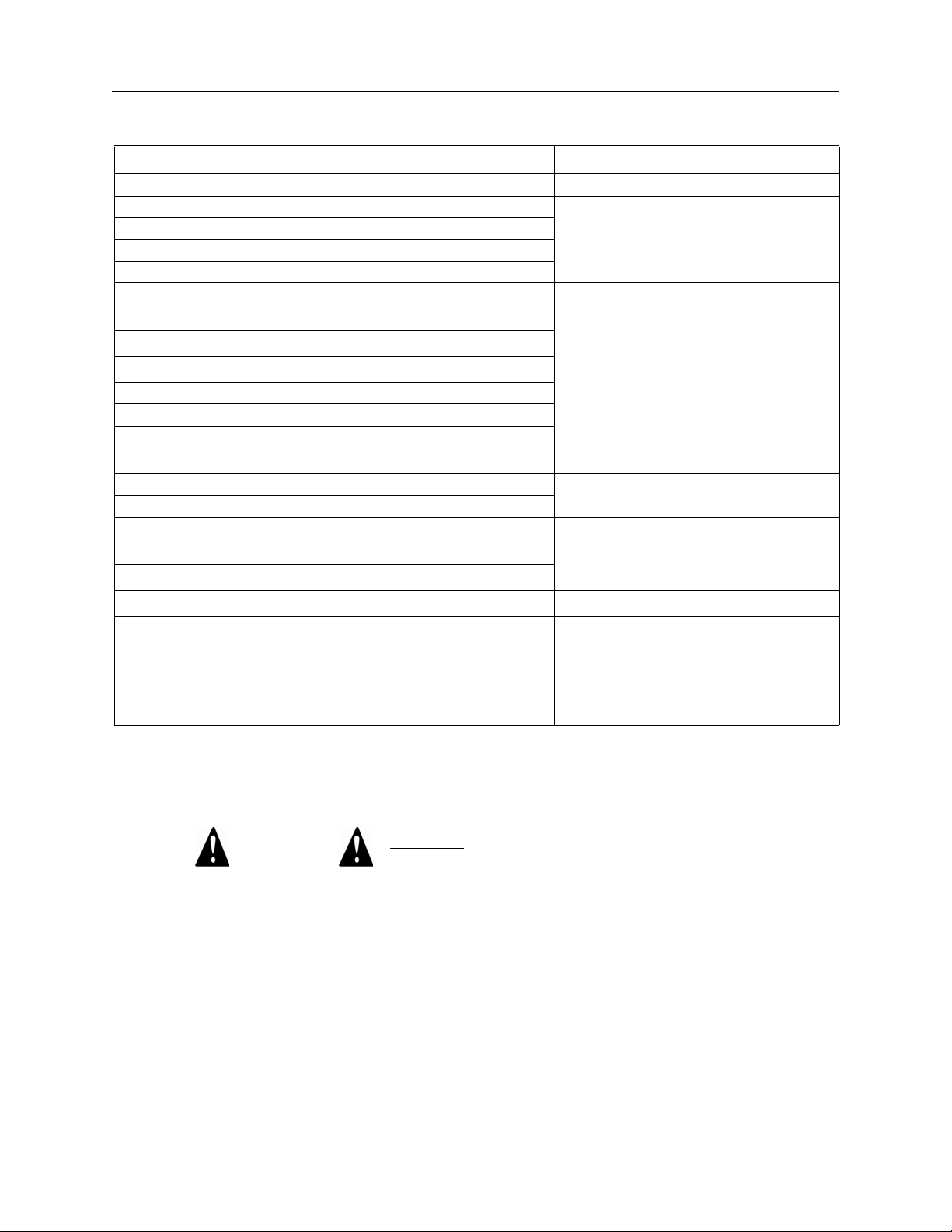
MODEL/SERIAL NUMBER LOCATION
The unit model and serial number plates is on the
frame under the seat as shown in the illustration.
The engine has its own model and serial number
identification. Consult the appropriate engine
manufacture’s service literature for the location and
translation of the engine model and serial number
information.
Transaxles also have their own model/serial
number.
2-2

SECTION 3 - GREASING AND LUBRICATION
SECTION 3 - GREASING AND LUBRICATION
CONTENTS
Section Description Page
Service Interval/Specification .................................................................................... 3-2
Lubrication Points ...................................................................................................... 3-3
3-1
SECTION 3 - GREASING AND LUBRICATION
SERVICE INTERVAL/SPECIFICATION
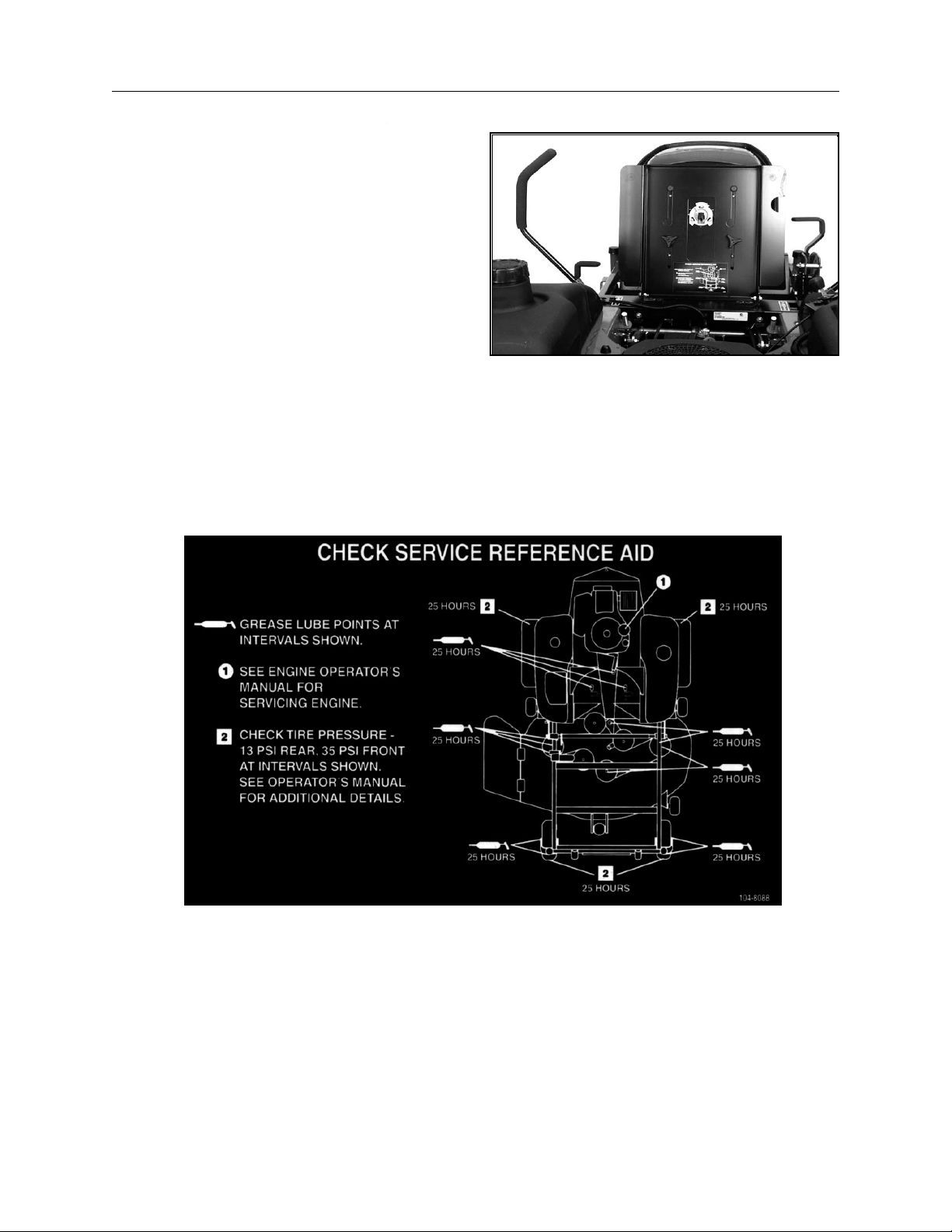
The unit should be greased every 25 hours; more
often when operating in dirty, dusty, or sandy
conditions.
A decal located under the seat shows the location
of all the grease zerks.
Grease Type: New Holland Ambra GR-9 multipurpose grease (General-purpose lithium base
grease).
3-2
SECTION 3 - GREASING AND LUBRICATION
LUBRICATION POINTS
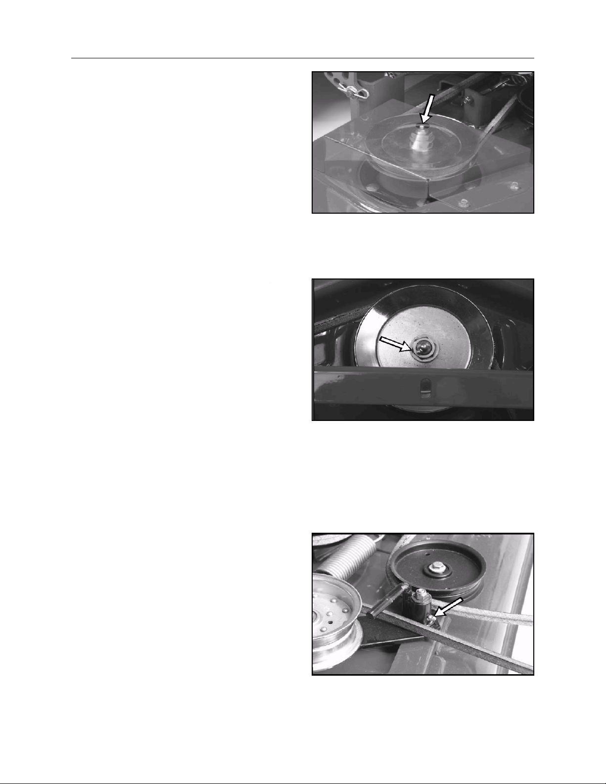
There is a grease fitting on the mower for right and
left outer spindle.
The grease zerk for the center mower spindle.
There is a grease fitting for the deck idler arm
bushing.
3-3
SECTION 3 - GREASING AND LUBRICATION
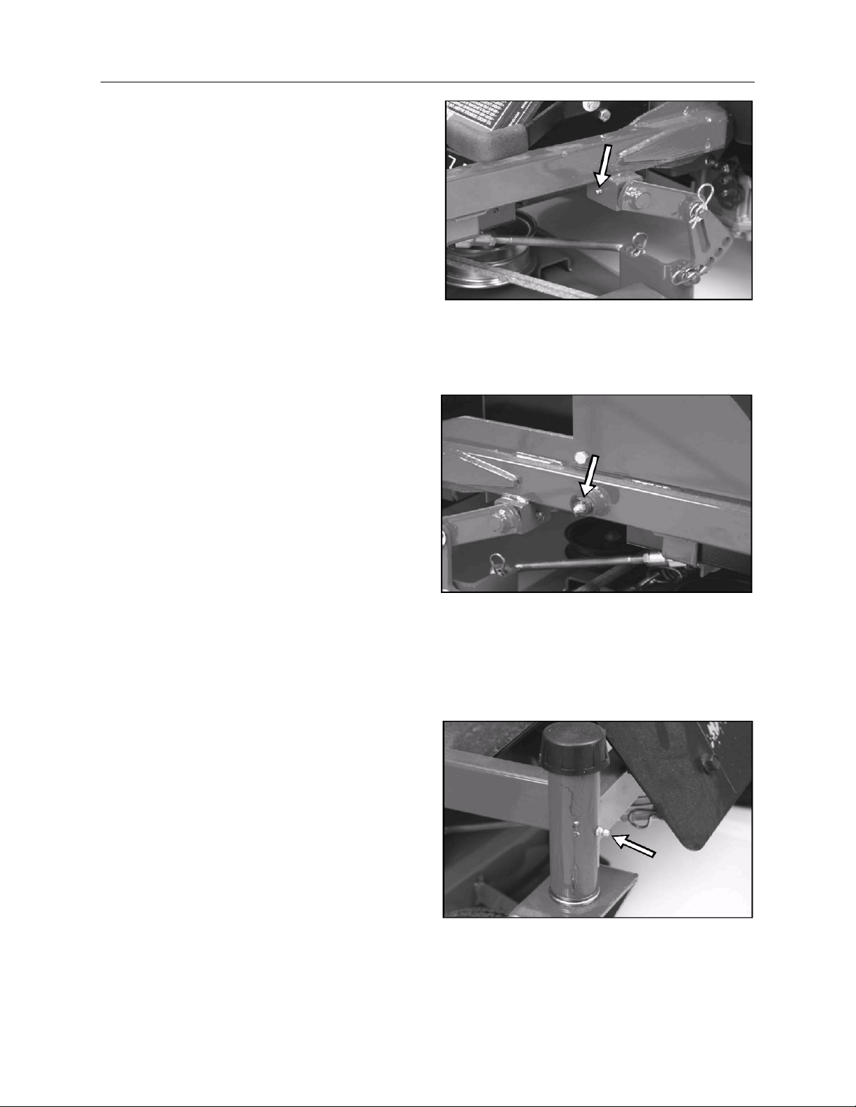
There are two grease fittings for the deck raising
pivot bushings - one on each side of the unit.
The grease zerk for the deck height adjustment
lever is on the right side of the machine.
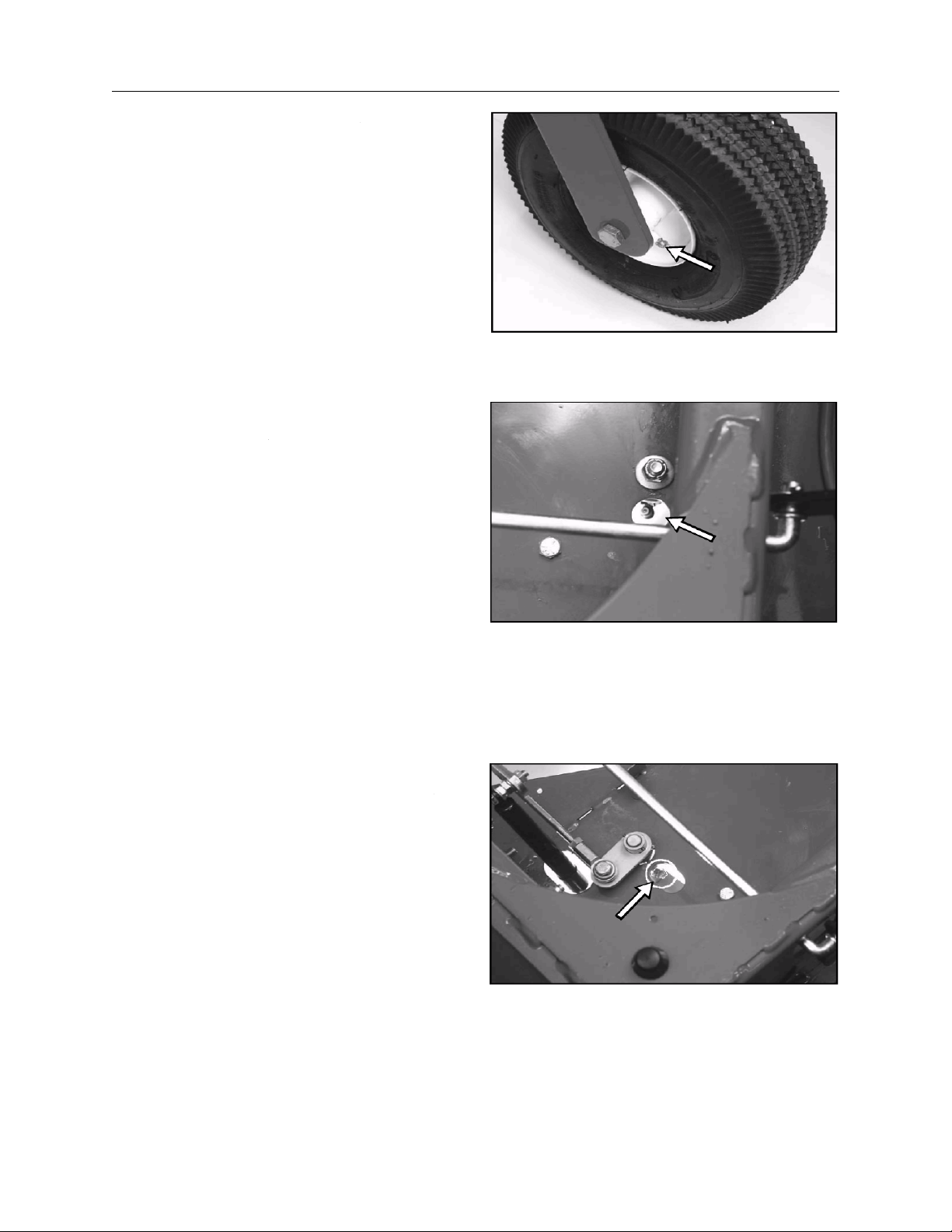
There are grease fittings for each front castor
bushing,
3-4
SECTION 3 - GREASING AND LUBRICATION
as well as the castor wheel bearings.
The zerk fitting for the traction belt idler bushing is
located under the seat.
Also under the seat are the fittings for the motion
control lever pivot bushings - one for each lever.
3-5

SECTION 3 - GREASING AND LUBRICATION
3-6

SECTION 4 - ENGINE
SECTION 4 - ENGINE
CONTENTS
Section Description Page
Kawasaki Engine ....................................................................................................... 4-2
Kawasaki Air Cleaner ................................................................................................ 4-2
Spark Plug ................................................................................................................. 4-3
Engine Remove and Replace .................................................................................... 4-4
4-1
SECTION 4 - ENGINE
KAWASAKI ENGINE
Oil Type: New Holland Ambra Super Gold
detergent oil (API service SC, SD, SE, SF, SG, or
SH).
Crankcase Capacity (with filter): 1.6 qt. (1.5 l).
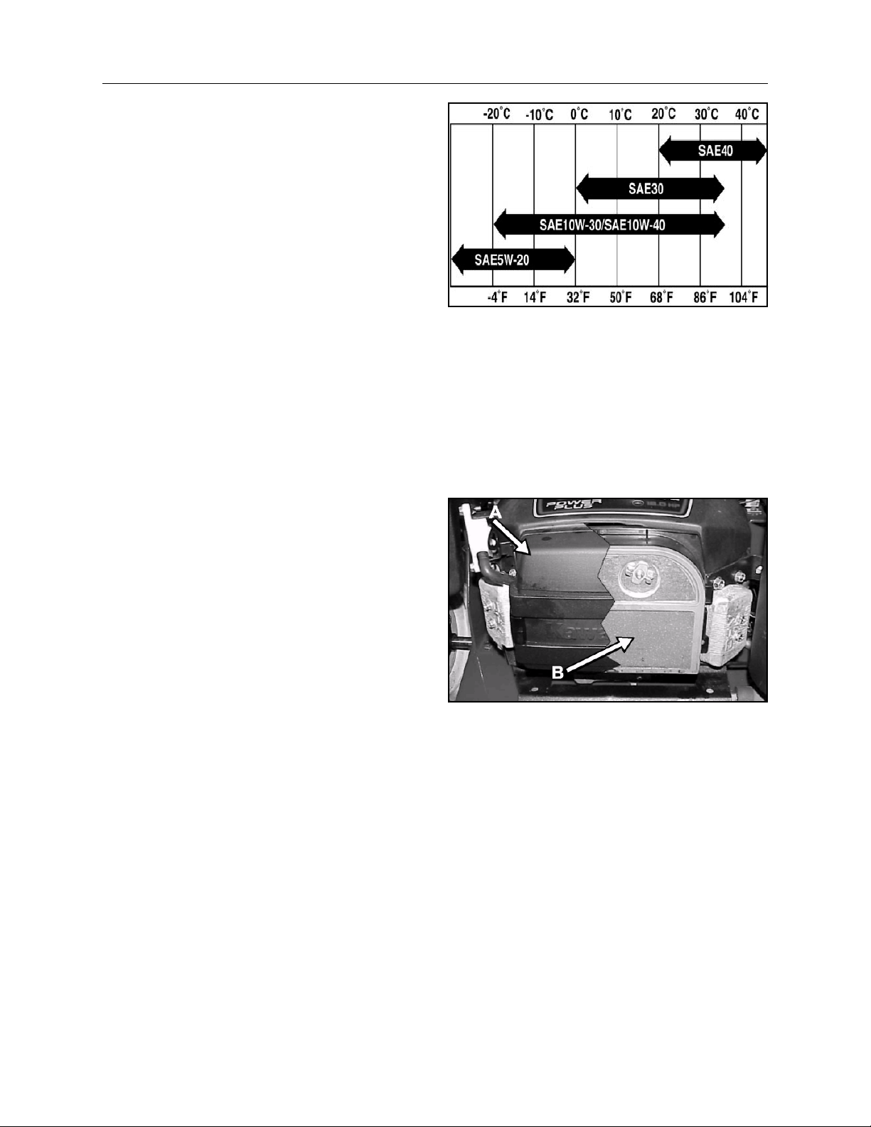
Viscosity: See table.
Change Oil:
• After the first use.
• Every 100 hours.
Change oil filter every 200 hours.
KAWASAKI AIR CLEANER
The air cleaner assembly consists of a paper filter
element and a foam precleaner.
To clean the paper element, tap lightly on a flat
surface to remove dust and dirt. Inspect the
element for tears, oil contamination, and damage
to the rubber seal.
NOTE: Never clean the paper element with
compressed air or solvents. If the element is dirty
or damaged, replace it immediately.
(A) COVER
(B) AIR FILTER
4-2
SECTION 4 - ENGINE
Every 25 hours (more often in dusty, dirty
conditions), wash the foam element in liquid soap
and warm water. When the element is clean, rinse
it thoroughly.
Dry the element by squeezing it in a clean cloth (do
not wring). Allow the element to air dry.
Follow engine manufacturer’s recommendation for
treatment of precleaner prior to installation.
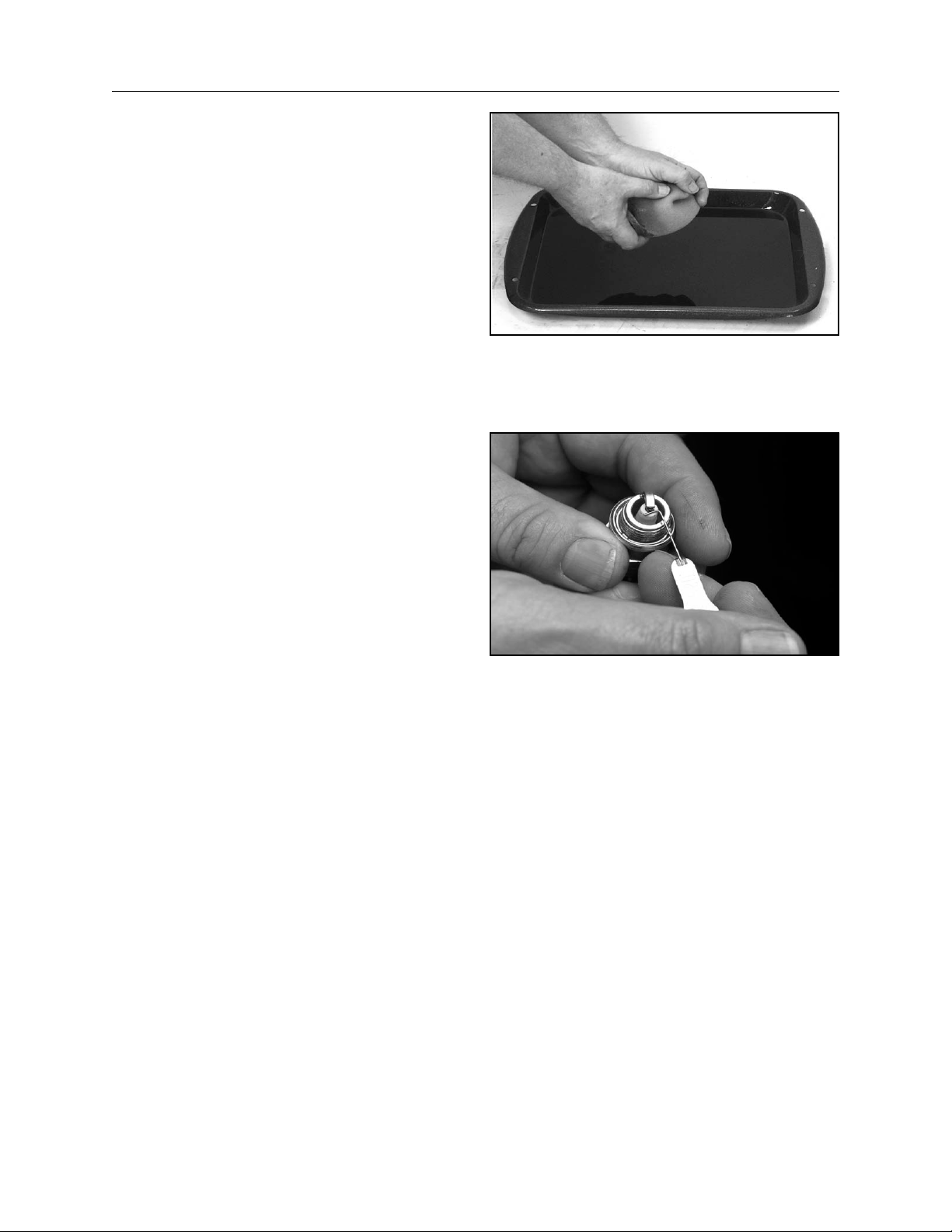
SPARK PLUG
On Kawasaki engines, replace the spark plug(s)
every 100 operating hours.
If the insulator on the spark plug(s) is light brown or
gray, the engine is running properly. A black
coating on the insulator indicates the air cleaner
may be dirty.
IMPORTANT: Never clean the spark plug(s).
Always replace the spark plug(s) when it has a
black coating, worn electrodes, an oily film, or
cracks.
Gap: .030” (0.76 mm)
Type: Champion RCJ86 (or equivalent)
4-3
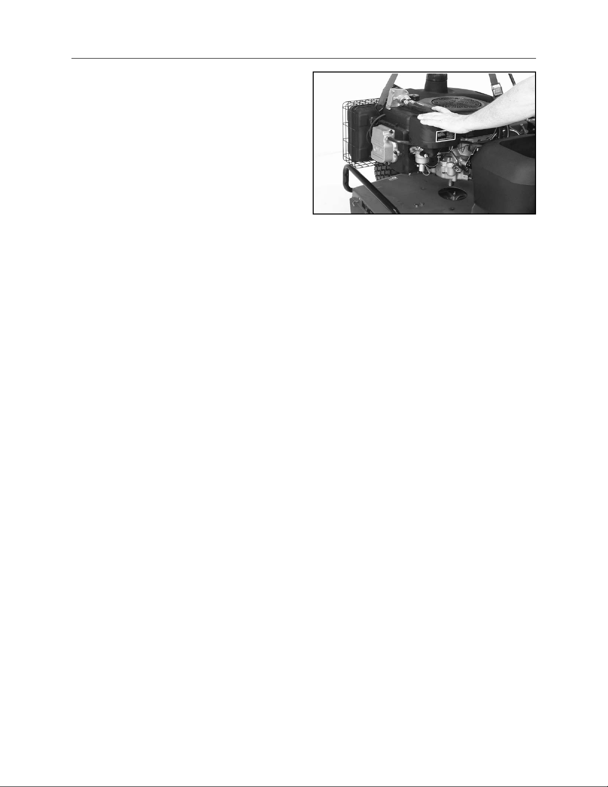
ENGINE REMOVE AND REPLACE
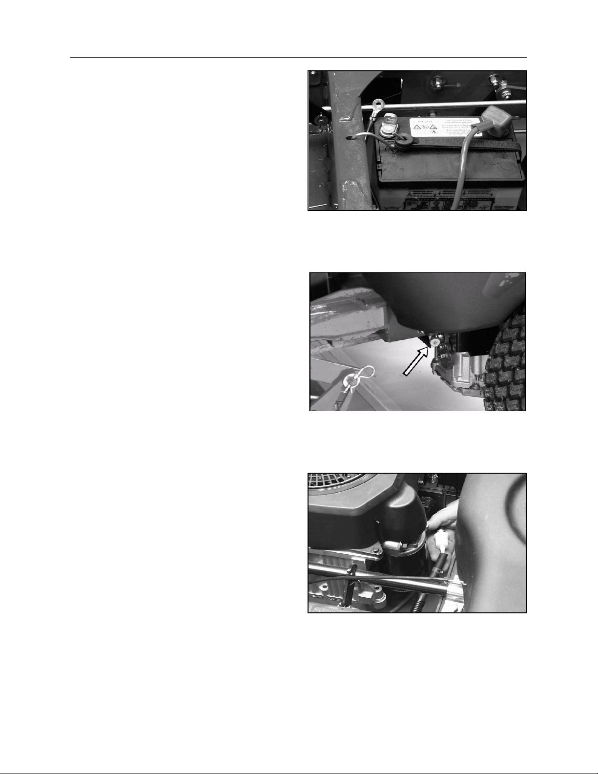
Disconnect the negative battery cable.
Close the fuel shut-off.
SECTION 4 - ENGINE
Remove the fuel line from the fuel filter.
4-4
SECTION 4 - ENGINE
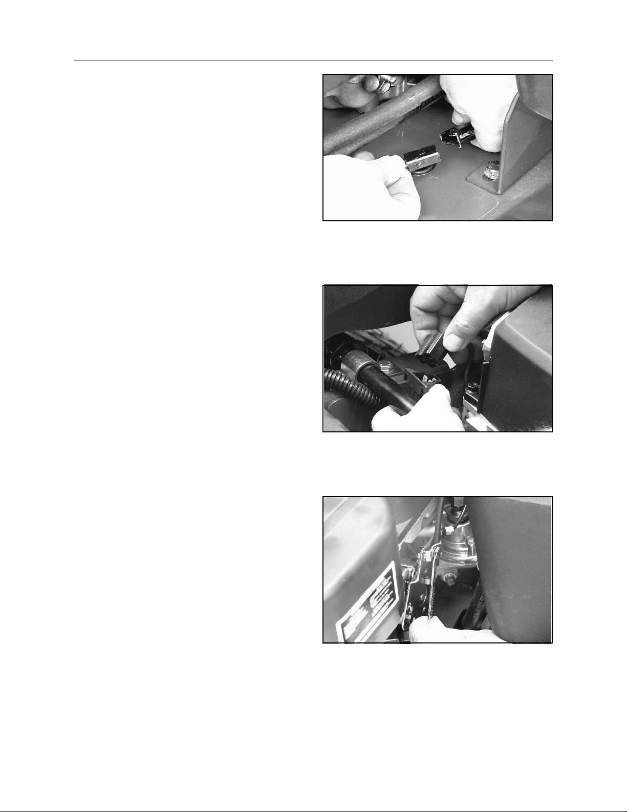
Disconnect the clutch PTO wiring.
Disconnect the engine wiring harness plug.
Loosen the throttle/choke clamp and remove the
cable from the governor linkage.
4-5
SECTION 4 - ENGINE
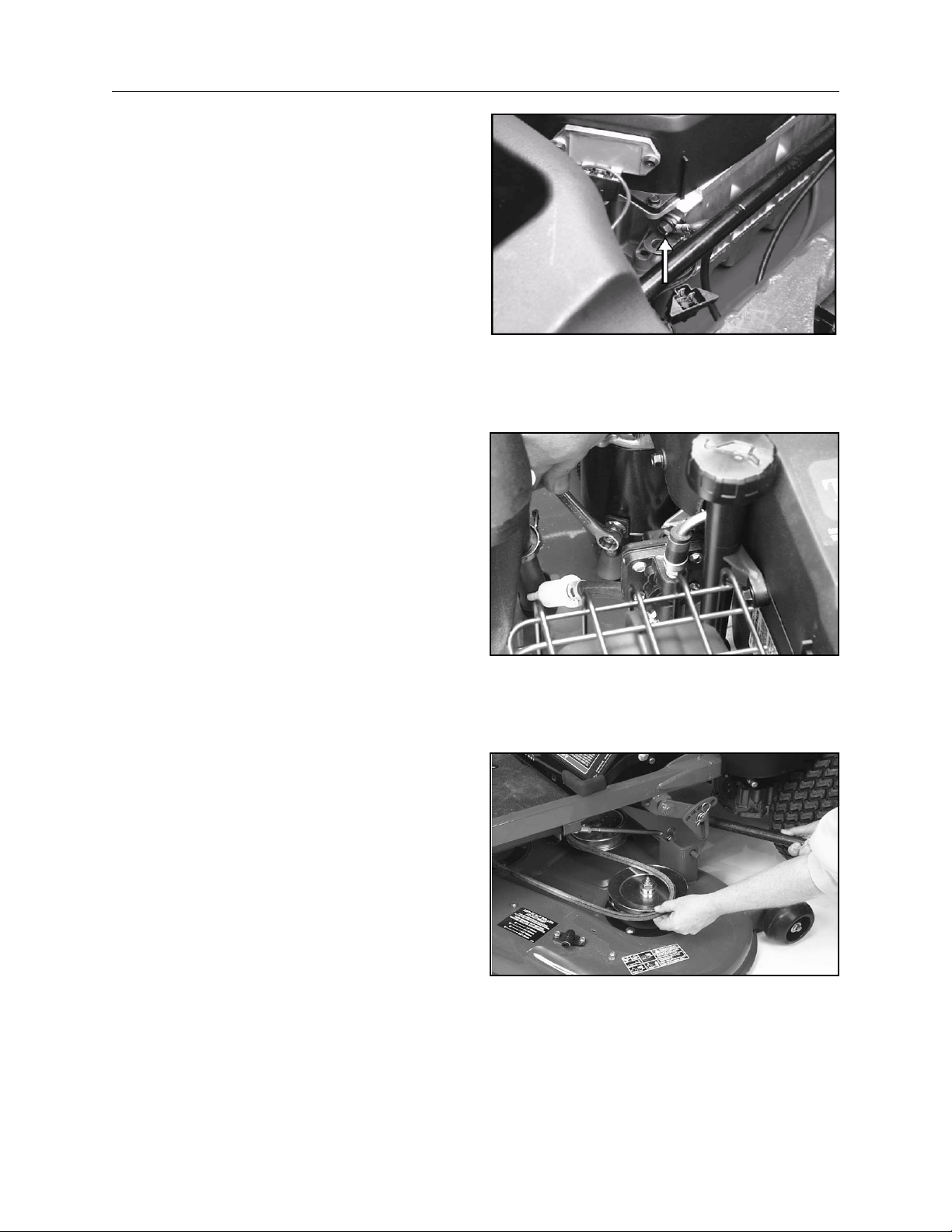
Remove the ground cable from the engine block.
Remove the starter cable.
Remove mower drive belt. See complete
procedure in Section 7, Mower Decks.
4-6
SECTION 4 - ENGINE
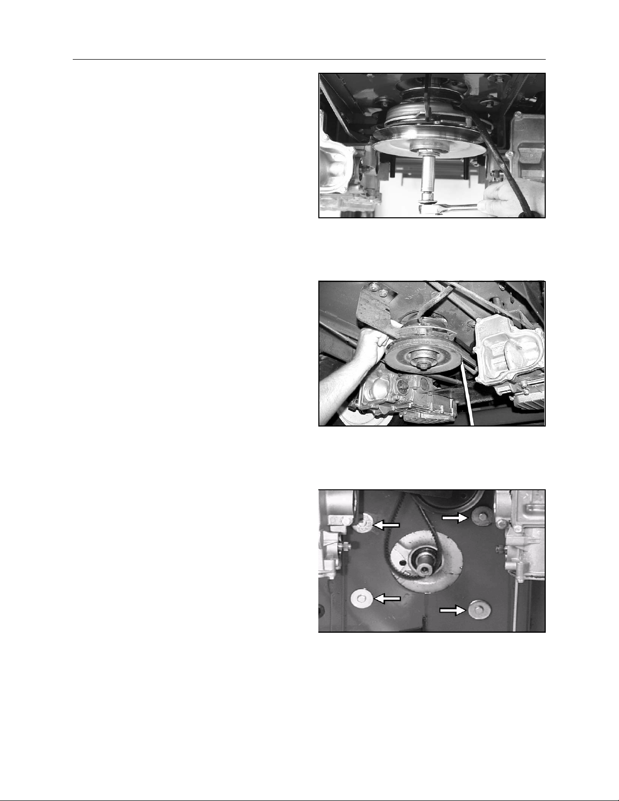
Remove the clutch bolt and lower the clutch
assembly.
Remove traction drive belt.
Move the idler pulley to lessen the tension on the
traction drive belt and slip the belt up off the engine
drive pulley. Then remove the clutch and drive
pulley from the crankshaft.
Remove the 4 engine mounting bolts.
4-7
Lift the engine from the chassis.
Reverse the above steps to replace.
SECTION 4 - ENGINE
4-8

SECTION 5 - TRANSAXLE
SECTION 5 - TRANSAXLE
CONTENTS
Section Description Page
Description and Operation ......................................................................................... 5-2
General Description ................................................................................................... 5-2
Hydraulic Schematic .................................................................................................. 5-3
Technical Specifications ............................................................................................ 5-6
Product Identification ................................................................................................. 5-6
Troubleshooting Checklist ......................................................................................... 5-7
Fluids ......................................................................................................................... 5-9
Fluid Change ............................................................................................................. 5-9
Control Handle-Return To Neutral Adjustment ........................................................ 5-10
Purging the System ................................................................................................. 5-12
Neutral Adjustment .................................................................................................. 5-14
Tracking Adjustment................................................................................................ 5-18
Control Handle Adjustment...................................................................................... 5-20
Remove and Replace Transaxle ............................................................................. 5-21
Reassembly............................................................................................................. 5-26
Repair ...................................................................................................................... 5-30
General Instructions ................................................................................................ 5-30
Limited Disassembly................................................................................................ 5-30
Back Cover .............................................................................................................. 5-32
Brakes ..................................................................................................................... 5-33
Brake Shaft and Bevel Gear.................................................................................... 5-34
Axle Shaft and Spur Gear........................................................................................ 5-35
Lower Housing and Filter......................................................................................... 5-37
Motor Shaft and Bevel Gear .................................................................................... 5-38
Center Section, Cylinder Blocks and Bypass .......................................................... 5-39
Input Shaft and Trunnion Arm.................................................................................. 5-41
Sealant Application .................................................................................................. 5-43
5-1
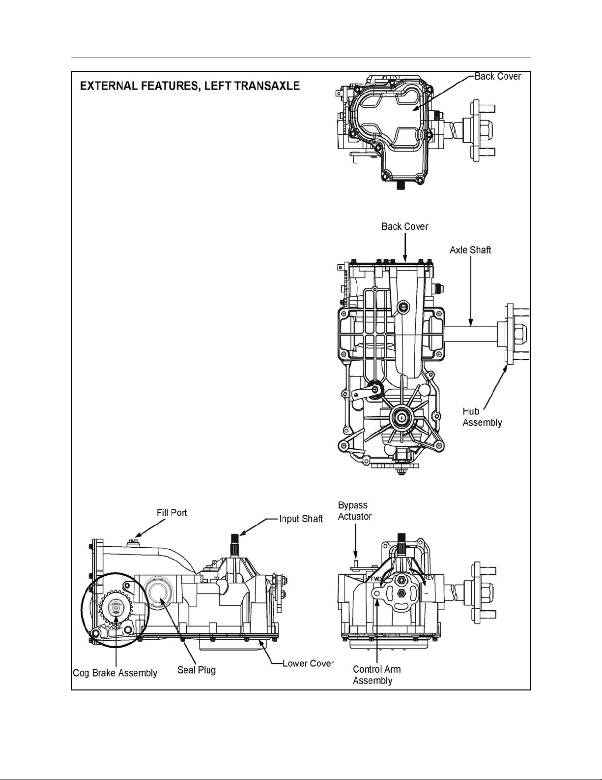
SECTION 5 - TRANSAXLE
DESCRIPTION AND OPERATION
This manual includes the transaxle general
description, hydraulic schematic, technical
specifications, servicing and troubleshooting
procedures.
The transaxle normally will not require servicing
during the life of the vehicle in which it is installed.
Should other servicing be required, the exterior of
the transaxle will need to be thoroughly cleaned
before beginning most procedures.
GENERAL DESCRIPTION
The transaxle is a self contained unit designed for
the transfer and control of power. It provides an
infinitely variable speed range between zero and
maximum in both forward and reverse modes of
operation.
This transaxle uses a variable displacement pump
with a maximum displacement of 10cc per
revolution, and motor with a fixed displacement of
21cc per revolution. The variable displacement
pump features a cradle mounted swashplate with a
direct-proportional displacement control. Reversing
the direction of the swashplate reverses the flow of
oil from the pump an thus reverses the direction of
the motor output rotation. The pump and motor are
of the axial piston design and utilize spherical
nosed pistons which are held against a thrust race
by internal compression springs.
The transaxle has a self contained fluid supply and
an internal filter. The fluid is forced through the filter
by a positive “head” on the fluid in the housing/
expansion tank with an assist by the negative
pressure created in the pump pistons as they
operate.
The check valves in the center section are used to
control the makeup flow of the fluid to the low
pressure side of the loop.
A bypass is utilized in this unit to permit moving the
vehicle for a short distance at a maximum of 2
m.p.h. (3.2 Km/h) without starting the engine.
WARNING
WARNING
Actuating the bypass will result in the loss of
hydrostatic braking capacity. The machine
must be stationary on a level surface and in
neutral when actuating the bypass.
5-2
SECTION 5 - TRANSAXLE
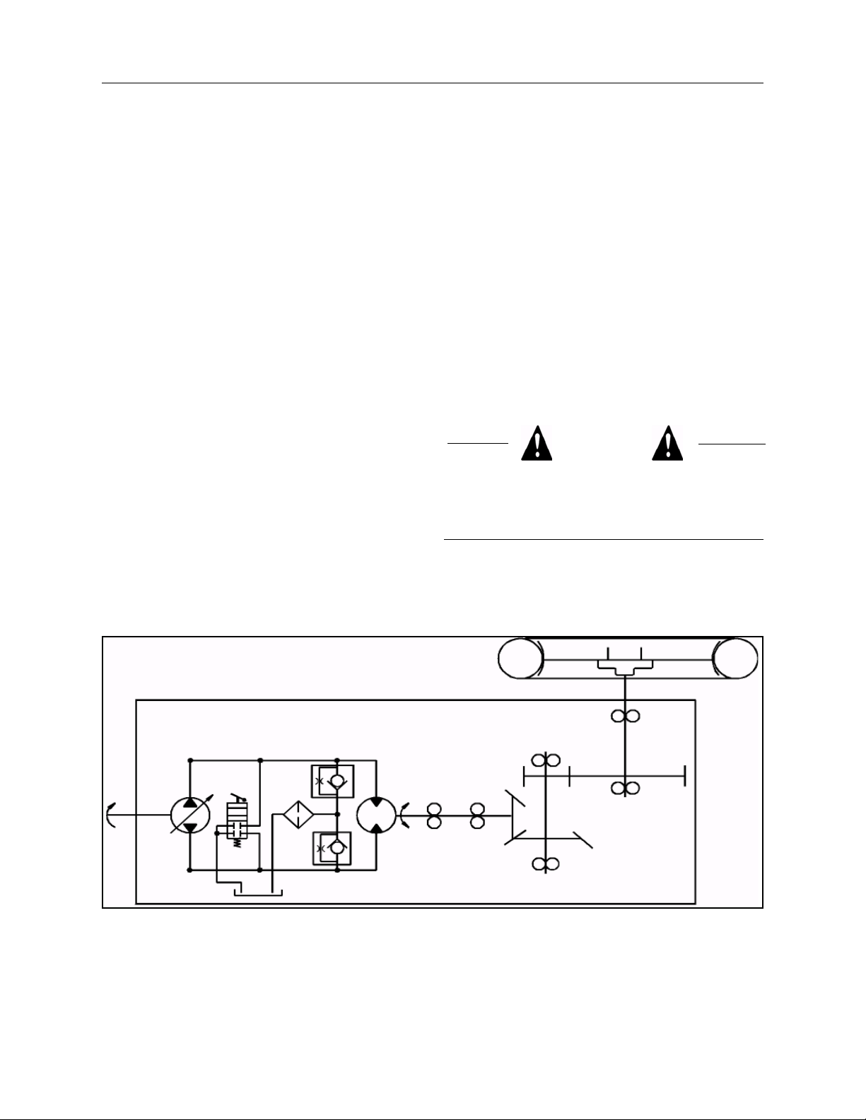
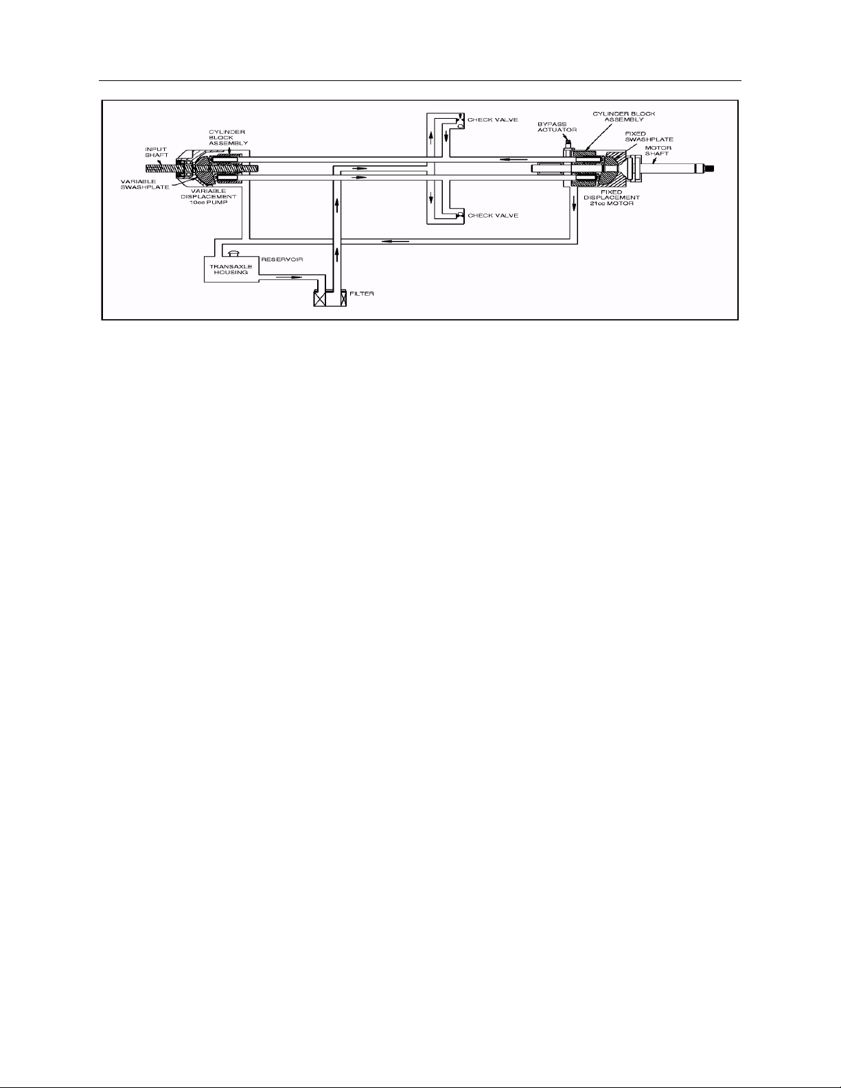
HYDRAULIC SCHEMATIC
The illustration above provides a flow diagram of
the hydraulic oil circuit. The oil supply for the
hydraulic system of the transaxle is also utilized for
lubricating the components of the final drive
assembly.
The input shaft and pump cylinder block are turned
in one direction only by the engine/drive belt/pulley
combination. Output of the oil flow is controlled by
the direction and amount that the variable
swashplate is angled. As the pump pistons
compress they force the oil to flow through one of
two passageways (forward or reverse) in the
center section to the motor cylinder block and
motor shaft. Since the motor has fixed
displacement angle it is forced to turn with the flow
of oil. As the angle of the pump swashplate is
increased the amount of oil being pumped will
increase and cause a higher speed output of the
motor. Reversing the angle of the swashplate will
reverse the direction of oil flow.
The motor cylinder block mounts onto a splined
motor shaft which drives the gear train.
The bypass feature in the transaxle has a
mechanical lever which lifts the motor block off of
the center section running surface, allowing any oil
flowing from the pump block to be discharged into
the housing without turning the motor.
During the operation of the transaxle, fluid is “lost”
from the hydraulic loop through leak paths
designed into the product for lubrication purposes
(around pistons, under the rotating cylinder blocks,
etc.). This “lost” fluid returns to the transaxle
housing, then is pulled back into one of the check
valves depending upon the direction of vehicle
operation. All of this oil must pass through an
internal filter.
5-3
SECTION 5 - TRANSAXLE
5-4

SECTION 5 - TRANSAXLE
5-5

SECTION 5 - TRANSAXLE
TECHNICAL SPECIFICATIONS
Overall Transaxle Reduction ......... 19.2:1
Input Speeds
Maximum...................................
Minimum....................................
Tire Diameter................................. 18 in; (45.7 cm) with 325 lbs; (147.4 kg) maximum weight on tires
Axle Shaft Options
Type...........................................
Diameter....................................
Type...........................................
Diameter....................................
Brake Type .................................... Cog, Parking
Weight of Unit................................ 30 lb; (14 kg)
PRODUCT IDENTIFICATION
3000 RPM
1800 RPM
Keyed/Double “D”
0.984 inch; (25.0 cm)
Flanged
Hub
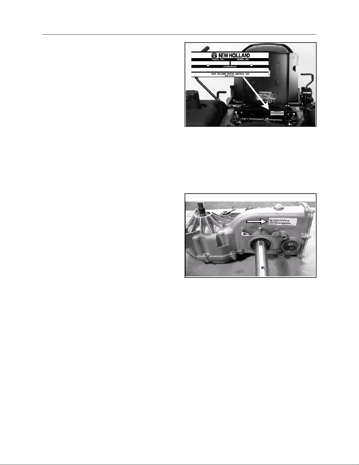
The model and configuration of the transaxle can
be determined from the label shown below.
5-6

SECTION 5 - TRANSAXLE
WARNING
WARNING
Do not attempt any servicing or adjustments
with the engine running. Use extreme caution
while inspecting the drive belt assembly, and
all vehicle linkage!
Follow all safety procedures outlined in the
vehicle owner’s manual!
TROUBLESHOOTING CHECKLIST
PROBLEM Possible Cause Corrective Action
Unit operates in one
direction only
Vehicle does not drive/
track straight
Control linkage bent or out of adjustment
Drive belt slipping or pulley damaged
Vehicle tires improperly inflated
In many cases problems with the drive system are
not related to a defective transaxle, but are caused
by slipping drive belts, partially engaged bypass
valves, and loose or damaged control linkages. Be
sure to perform all operational checks and
adjustments before assuming the unit is
malfunctioning. The table below provides a
troubleshooting check list to help determine the
cause of operational problems.
Repair or replace linkage
Repair or replace drive belt or pulley
Inflate to recommended pressure.
Check tire diameters are approximately equal, side-to-side
Control linkage bent, loose, or out of
adjustment
Bypass partially engaged.
Unit is noisy Oil level low or contaminated oil
Excessive loading
Brake setting incorrect
Loose parts
Bypass assembly sticking
Air trapped in hydraulic system
Repair, adjust, or replace vehicle
linkage
Adjust bypass linkage
Fill to proper level or change oil
Reduce vehicle loading
Adjust brake to proper setting
Repair or replace loose parts
Repair or replace valve or linkage
Purge hydraulic system
5-7

SECTION 5 - TRANSAXLE
PROBLEM Possible Cause Corrective Action
Unit has no/low power Engine speed low
Control linkage bent or out of adjustment
Brake setting incorrect
Drive belt slipping or pulley damage
Oil level low or contaminated oil
Excessive loading
Bypass assembly sticking
Air trapped in hydraulic system
Unit operating hot Debris buildup around transaxle
Brake setting incorrect
Cooling fan damaged
Oil level low or contaminated oil
Adjust to correct setting
Repair or replace linkage
Adjust brake to proper setting
Repair or replace drive belt or pulley
Fill to proper level or change oil
Reduce vehicle loading
Repair or replace valve or linkage
Purge hydraulic system
Clean off debris
Adjust brake to proper setting
Repair or replace cooling fan
Fill to proper level or change oil
Excessive loading
Air trapped in hydraulic system
Transaxle leaks oil Damaged seals, housing, or gaskets
Air trapped in hydraulic system
Reduce vehicle loading
Purge hydraulic system
Replace damaged components
Purge hydraulic system
5-8

SECTION 5 - TRANSAXLE
FLUIDS
Engine oil with a minimum rating of 55 SUS at 212
F° and an API classification of SH/CD is
recommended. A 20W-50 engine oil has been
selected for use by the factory and is
recommended for normal operating temperatures.
Check oil level when cold. To check the transaxle
fluid level, remove the vent. Oil level should be
1-7/8” - 2-3/16” (4.8 cm - 5.56 cm) from the top of
the vent port.
The oil level can only be checked when the
transaxle is removed from the machine.
FLUID CHANGE
This transaxle is factory filled, sealed and does not
require oil maintenance. However, in the event of
oil contamination or degradation, oil addition or
change may alleviate certain performance
problems.
It is essential that the unit exterior be free of debris
prior to fluid maintenance. The transaxle must be
removed from the vehicle for oil drainage from the
top.
5-9

SECTION 5 - TRANSAXLE
CONTROL HANDLE-RETURN TO
NEUTRAL ADJUSTMENT
1. With the engine off, move the directional
control handles to the reverse position.
2. Let the handles go. They should return to the
neutral position, which means the handle
should line up with the neutral slot (neutral
lockout position).
3. If adjustment is needed:
A. Lift the seat and locate the adjusters.
Loosen the jam nut on the yoke.
5-10

SECTION 5 - TRANSAXLE
B. Turn the top bolt head until the directional
control handle is lined up with the neutral
slot (Neutral Lockout Position).
C. Tighten the jam nut and then test the
directional control handle by pulling the
handle in reverse and then let the handle
go. It should return to the neutral slot.
D. Before starting the unit, follow the
procedures on Purging the System.
5-11

SECTION 5 - TRANSAXLE
PURGING THE SYSTEM
Due to the effect air has on efficiency in hydrostatic
drive applications, it is critical that it be purged from
the system.
These purge procedures should be implemented
any time a hydrostatic system has been opened to
facilitate maintenance or any additional oil has
been added to the system.
Air creates inefficiency because its compression
and expansion rate is higher than that of the oil
normally approved for use in hydrostatic drive
systems.
The following procedures should be performed with
the vehicle drive wheels off the ground, the seat
switch temporarily bypassed, and the brake arm
completely disengaged from the brake cog, (see
Parking Brake Adjustment, Section 6). The
procedure may need to be repeated under normal
operating conditions.
1. With the bypass valves open (hand push
mode) and the engine running, slowly move
the directional control handles in both forward
and reverse directions 5 to 6 times, to purge
trapped air from the unit.
5-12

SECTION 5 - TRANSAXLE
2. Place the bypass valves in the closed position
(operating). With the engine running, slowly
move the directional control handles through
the forward and reverse directions (5 to 6
times).
3. It may be necessary to repeat steps 1 and 2
until all the air is completely purged from the
system. When the transaxle moves forward
and reverse at normal speed, purging is
complete.
5-13

SECTION 5 - TRANSAXLE
NEUTRAL ADJUSTMENT
1. If the unit creeps in neutral, it will be necessary
to make an adjustment to the transaxle.
2. Operate the unit to determine which transaxle
needs adjustment.
3. Raise the unit and place it on jack stands.
4. Warm the transaxle fluid by running for at least
10 minutes.
5. Unplug the seat switch and temporarily
connect a jumper wire across the plug
connector.
5-14

SECTION 5 - TRANSAXLE
6. Place the directional control handles in the
neutral lockout position. Start the engine and
run at half throttle.
7. The rear traction wheels should remain
stationary or creep slightly in reverse.
8. If necessary, loosen the jam nuts (A) and turn
the control rod until the wheel stops between
forward and reverse. In some cases, you may
have a slight creep in reverse. When you lower
the unit to the ground, it should stop.
5-15

SECTION 5 - TRANSAXLE
9. After you have a adjusted the rods, move the
directional control handle in reverse position,
then let go of the handles. The handles should
move to the neutral position and the drive
wheels should remain stationary, or have a
very slight amount of creep in reverse. The
wheels should not creep in the forward
direction when the control handles are in the
neutral lock out position.
10. Run the engine at full throttle. Check neutral
again by moving the directional control handles
in reverse, then let go of the handles. The
handles should move to the neutral position
and the dive wheels should not move. A slight
creep could be observed when the machine is
elevated. However, when lowering the unit to
the ground, the weight of the unit should stop
the creep.
11. When the adjustment is complete, hold the
control rod stationary with pliers and tighten
the jam nuts. Always test again to make sure
the unit is still neutralized.
5-16

SECTION 5 - TRANSAXLE
12. Remove the jumper wire on the seat switch
and plug the switch into the harness. Lower the
unit to the ground.
5-17

SECTION 5 - TRANSAXLE
TRACKING ADJUSTMENT
When operating the unit in forward, it is not
unusual for the unit to track slightly right or left
when going for a distance. This is because of the
different tolerances between two different
hydrostatic pumps. If the tracking deviation is
large, check the following.
NOTE: Ground surface should be level when
checking the tracking.
1. Check the tire pressure in each tire. 13 psi (90
kPa) rear, 35 psi (241 kPa) front. Tire pressure
has a great influence on the tracking of these
units.
It is advisable to check for a large deviation in
outside diameter of the tires, side-to-side, if the
tracking error is severe. Also, check that the
front casters rotate freely, and the front wheel
bearings are in good condition.
2. You may be able to make a slight tracking
adjustment by turning the neutral control rods
without affecting the neutral position.
IMPORTANT: Be sure to recheck the neutral
adjustment to be sure the machine does not creep
after correcting the tracking.
5-18

SECTION 5 - TRANSAXLE
NOTE: All of the control linkage is set up for
forward motion. It is not unusual to have a large
tracking error when going a distance in reverse. Do
not try to adjust reverse tracking. If you do, it will
misadjust the forward linkage.
3. After attempting any tracking change with the
unit, make sure it is still neutralized.
5-19

SECTION 5 - TRANSAXLE
CONTROL HANDLE ADJUSTMENT
If the directional control handles do not line up with
each other, they require adjustment.
1. Loosen the bolts attaching the handles to the
control linkage.
2. Adjust the position of the handles so that they
are aligned. Tighten the bolts after adjustment.
5-20

SECTION 5 - TRANSAXLE
REMOVE AND REPLACE TRANSAXLE
Disconnect the battery.
Close the fuel shut-off.
Raise the rear of the unit and support it with jack
stands.
5-21

SECTION 5 - TRANSAXLE
Remove the clip that secures the vent hose to the
chassis.
If necessary, engage the parking brake to facilitate
wheel removal.
Remove the wheel assembly.
5-22

SECTION 5 - TRANSAXLE
Remove the parking brake link from the brake arm.
Disconnect the motion control link from the
transaxle.
Remove the hairpin cotter and washer from the
bypass valve lever. Leave the rod in place.
5-23

SECTION 5 - TRANSAXLE
Move the idler pulley to lessen the tension on the
traction drive belt and slip the belt up off the engine
drive pulley.
Remove the belt from the transaxle being
removed.
Loosen and remove the six bolts and washer
between both transaxles. Remove the hydro lower
plate. Note the orientation of the hydro lower plate.
It must be reinstalled with the lip facing down,
toward the front.
5-24

SECTION 5 - TRANSAXLE
Support the transaxle with a jack while removing
the last bolts.
Guide the transaxle as it is lowered. Make sure the
cooling fan and vent hose clear the chassis.
5-25

SECTION 5 - TRANSAXLE
REASSEMBLY
IMPORTANT: Before installing a new transaxle,
check the oil level and check the torque on the nut
retaining the input pulley. Torque to 30 - 35 ft. lbs.
(40.7 N·m - 47.5 N·m).
Use a jack to lift the transaxle into the chassis.
Carefully guide it into position so that the cooling
fan does not catch on the chassis and the bypass
rod is properly positioned in the lever. Insert the
vent hose through the slot provided for it in the
frame.
Install the two axle bolts, washers, and nuts to the
frame. Do not tighten the bolts. Reinstall the rest of
the bolts, washers, and nuts in the lower hydro
plate. If the plate was completely removed, make
sure the lip of the plate is pointing to the front and
down. Tighten the transaxle bolts and nuts
following the sequence shown in the photo. Torque
the bolts and nuts to 200 in. lbs. (22.6 N·m).
5-26

SECTION 5 - TRANSAXLE
Place the traction belt on the pulley. Check for
correct belt routing.
(A) Engine Pulley
(B) Idler Pulley
(C) Right Hydro
(D) Left Hydro
Install the hairpin cotter pin and washer on the
bypass valve lever.
Reinstall the motion control link.
5-27

SECTION 5 - TRANSAXLE
NOTE: The length of the link is set at the factory
and should not normally require adjustment in the
field.
If the link has been tampered with, the distance
between bolt centers is:
• Left side 3.6” (9.14 cm)
• Right side 3.1” (7.9 cm)
Install the parking brake linkage.
Replace the wheel assembly.
5-28

SECTION 5 - TRANSAXLE
Secure the vent hose to the chassis.
Recheck to make sure the brake arm clears the
teeth of the brake cog when the park brake is
disengaged.
5-29

SECTION 5 - TRANSAXLE
REPAIR
Each subassembly illustrated in this section is
illustrated by an exploded view showing the parts
involved. The item reference numbers in each
illustration are for assembly instructions only. A
complete exploded view and item list of the
transaxle is provided at the end of this section.
Many of the parts and subassemblies of this
transaxle can be removed and serviced
independently of other components. Where some
components and assemblies must be removed
before a given assembly can be serviced, that
information is given at the beginning of the
disassembly instructions.
GENERAL INSTRUCTIONS
Cleanliness is a primary means of assuring
satisfactory life on repaired units. Thoroughly clean
all exposed surfaces prior to any type of
maintenance. Cleaning of all parts by using a
solvent wash and air drying is usually adequate. As
with any precision equipment, all parts must be
kept free of foreign material and chemicals.
Upon removal, it is recommended that all seals, Orings, and gaskets be replaced. During installation
lightly lubricate all seals, O-rings, gaskets with a
clean petroleum jelly prior to assembly. Also
protect the inner diameter of seals by covering the
shaft with a cellophane (plastic wrap, etc.) material.
Parts requiring replacement must be replaced
using only original New Holland parts.
LIMITED DISASSEMBLY
The following procedures are presented in the
order in which they must be performed to
completely disassemble the unit. Do not
disassemble the unit any further than is necessary
to accomplish the required repairs. Each
disassembly procedure is followed by a
corresponding assembly procedure.
Reassembly is accomplished by performing the
“Assembly” portions of the procedures. If the unit
has been completely disassembled, a summary of
the assembly procedures, in the order in which
they should occur.
Protect all exposed sealing surfaces and open
cavities from damage and foreign material. The
external surfaces should be cleaned before
beginning any repairs.
5-30

SECTION 5 - TRANSAXLE
REQUIRED TOOLS
Miscellaneous Sockets
MZ19H Service & Repair Manual 3/8”
Flat Blade Screw Driver 1/2”
Torque Wrench 7/16”
Air Impact Wrench 9/16”
Rubber Mallet E-8 Torx Head
Pliers Wrenches
Needle Nose 1/2”
Large External Snap Ring
Small External Snap Ring
Large Internal Snap Ring
REQUIRED TORQUE VALUES
Operation U.S. Torque Metric Torque Item Description
Wheel Hub Nut 200-295 ft-lbs 271-400 Nm 108 Nut, hex 3/4-16
Fan/Pulley Nut 360-520 in-lbs 41-59 Nm 49 Nut, hex lock 1/2-20
Back Cover Screws 110-150 in-lbs 12-17 Nm 50 Screw, 1/4-20
Friction Pack Stud 50-120 in-lbs 6-14 Nm 36 Stud, 5/16-24
Control Arm Nut 180-240 in-lbs 20-27 Nm 35 Nut, 5/16-24
Control Bolt 192-252 in-lbs 22-28 Nm 76/121 Nut/Bolt, 5/16-18
Brake Yolk Screw 80-120 in-lbs 9-14 Nm 123/211 Screw, 1/4-28
Cog Brake Arm Screw 110-150 in-lbs 12-17 Nm 123 Screw, hex 1/4-20
Check Plug Assembly 200-360 in-lbs 23-41 Nm 45 Check plug assembly
Lower Housing Screw 110-150 in-lbs 12-17 Nm 50 Screw, 1/4-20
Center Section Screw 525-700 in-lbs 59-79 Nm 44 Screw, 3/8-24
Lock Down Screw 210-270 in-lbs 24-30 Nm 208 Screw, 5/16-24 (Lock Down
5-31

SECTION 5 - TRANSAXLE
BACK COVER
DISASSEMBLY
1. Remove the eight screws, 50, from the back
cover, 13, and discard.
2. Remove the back cover, 13. Take care not to
damage the casting surfaces.
3. Clean off the sealant from the mating surfaces
of the back cover, 13, and the main housing
assembly, 1.
INSPECTION
1. Inspect the back cover, 13, for excessive wear
or damage.
ASSEMBLY
1. Apply sealant to the back cover, 1. Refer to
Sealant Application.
2. Place the back cover, 13, onto the main
housing assembly, 1.
3. Install the eight replacement screws, 50, to
secure the back cover, 13, to the main housing
assembly, 1. Tighten the eight screws, 50, to
the torque value listed in the table above.
5-32

SECTION 5 - TRANSAXLE
BRAKES
DISASSEMBLY
1. Remove the external retaining ring, 63.
2. Remove the brake bolt, 123, brake arm, 70,
and brake disc, 73.
NOTE: The orientation of the hub on the brake
disc.
INSPECTION
1. Inspect the brake disc, 73, for damaged
splines or gear teeth.
2. Inspect the brake arm, 70, for damaged teeth.
ASSEMBLY
1. Insert the brake shaft, 55, into the main
housing, 1. Slide the brake disc, 73, onto the
brake shaft, 55.
NOTE: The orientation of the brake disc. The
hub on the brake disc should face inward on
right hand units and outward on left hand units.
2. Install the brake arm, 70, and brake bolt, 123,
onto the main housing, 1. Tighten the brake
bolt, 123, to the torque value listed in the
above table.
3. Install an external retaining ring, 63, onto the
brake shaft, 55.
5-33

SECTION 5 - TRANSAXLE
BRAKE SHAFT & BEVEL GEAR
DISASSEMBLY
1. Remove the back cover. See Back Cover.
2. Remove the brake. See Brakes.
3. Remove the brake shaft lip seals, 58, and
retaining rings, 126. Discard the lip seals, 58.
4. Remove the retaining ring, 67, from the outside
of the ball bearing, 26.
5. Remove the brake shaft, 55, and ball bearing,
26, from the 19 tooth bevel gear, 53. It may be
necessary to tap lightly on the brake shaft, 55,
to remove the bearing, 26.
6. Remove the 19 tooth bevel gear, 52.
INSPECTION
1. Inspect the brake shaft, 55, ball bearing, 26,
and bevel gear, 52, for wear or damage.
ASSEMBLY
1. Insert the brake shaft, 55, and ball bearing, 26,
into the main housing, 1, allowing the brake
shaft, 55, to pass through the 19 tooth bevel
gear, 52.
2. Install the retaining ring, 67.
3. Install the brake shaft lip seals, 58, and
retaining rings, 126.
4. Install the brake. See Brakes.
5. Install the back cover. See Back Cover.
5-34

SECTION 5 - TRANSAXLE
AXLE SHAFT & SPUR GEAR
DISASSEMBLY
1. Remove the back cover. See Back Cover.
2. Remove the brake. See Brakes.
3. Remove the brake shaft and bevel gears. See
Brake Shaft & Bevel Gears.
4. Remove the hub assembly, 107, if not already
removed.
NOTE: The orientation of the hub and axle to
the main housing is critical in reassembly.
5. Remove the retaining ring, 68, from the outside
of the axle shaft seal.
6. Remove the axle shaft seal, 66, and discard.
7. Remove the retaining ring, 68, from the outside
of the side seal plug, 60.
8. Remove the side seal plug, 60, by lightly
tapping on the end of the axle shaft, 56, with a
plastic or rubber mallet. Discard the side seal
plug, 60.
9. Remove the axle shaft retaining ring, 62, from
the axle shaft, 56.
ASSEMBLY
1. Place the spur gear, 53, and axle bushings, 81
& 82, per noted orientation, into the main
housing, 1.
2. Insert the axle shaft bearings, 64, and axle
shaft, 56, into the main housing, 1. (A clean
screwdriver may be used to help align the gear
and bushings during installation).
3. Place the axle retaining ring, 62, onto the end
of the axle shaft, 56.
4. Using a rubber or plastic mallet, lightly tap a
new side seal plug, 60, into the main housing,
1. Install the seal plug retaining ring, 68.
5. Slide the axle shaft bearing, 65, onto the hub
end of the axle shaft, 56.
6. Slide the axle seal, 66, onto the axle shaft, 56.
Remember to protect the seal, 66, during
installation by covering the axle shaft, 56, with
cellophane. Remove the cellophane once the
seal, 66, is installed.
7. Install the retaining ring, 68.
8. Install the hub assembly, 107, and nut, 108,
with the bolt threads facing away from the
transaxle.
10. Remove the axle shaft, 56, from the main
housing assembly, 1. Remove the ball
bearings, 64 & 65, from the axle shaft, 56.
Remove the two axle shaft bushings, 81 & 82,
and spur gear, 53, from the inside of the main
housing, 1.
NOTE: The orientation of the axle shaft
busings, 81 & 82. This is important for
reassembly.
INSPECTION
1. Inspect the ball bearings, 64 & 65, and axle
shaft, 56, for wear or damage.
2. Inspect the spur gear, 53, for wear or damage.
9. Install the brake shaft and bevel gear. See
Brake Shaft and Bevel Gear.
10. Install the brake. See Brakes.
11. Install the back cover. See Back Cover.
5-35

SECTION 5 - TRANSAXLE
5-36

SECTION 5 - TRANSAXLE
LOWER HOUSING & FILTER
DISASSEMBLY
1. Remove the ten screws, 50, holding the lower
housing, 2, to the main housing, 1, and
discard.
2. Remove the lower housing, 2, and old sealant.
Take care not to damage the casting surfaces.
3. Remove and discard the internal filter, 46.
INSPECTION
1. Inspect the lower housing, 2, for excessive
wear or damage.
ASSEMBLY
1. Install a new filter, 46.
2. Apply sealant to the lower housing, 2, where
the lower housing, 2, mates with the main
housing, 1. Refer to Sealant Application.
3. Place the lower housing, 2, on the main
housing, 1.
4. Install the ten replacement screws, 50, that
hold the lower housing, 2, to the main housing,
1.
5. Torque the ten screws, 50, to the value listed in
the table.
5-37

SECTION 5 - TRANSAXLE
MOTOR SHAFT & BEVEL GEAR
DISASSEMBLY
1. Remove the back cover. See Back Cover.
2. Remove the brake. See Brakes.
3. Remove the brake shaft and bevel gear. See
Brake Shaft & Bevel Gear.
4. Remove the axle shaft and spur gear. See Axle
Shaft & Spur Gear.
5. Remove the 14 tooth bevel gear, 51, from the
motor shaft, 54.
6. Remove the motor shaft, 54, wire retaining
ring, 27, and bearing assembly, 26, from the
main housing, 1.
NOTE: The bearing, 26, does not fit flush with
the housing. This is important for reassembly.
ASSEMBLY
1. Install the motor shaft, 54, bearing assembly,
26, and wire retaining ring, 27.
NOTE: The splines must be aligned when
inserting the motor shaft, 54.
2. Install the 14 tooth bevel gear, 51, on the end
of the motor shaft, 54.
3. Install the axle shaft and spur gear. See Axle
Shaft & Spur Gear.
4. Install the brake shaft and bevel gear. See
Brake Shaft & Bevel Gear.
5. Install the brake. See Brakes.
6. Install the back cover. See Back Cover.
INSPECTION
1. Inspect the gear, 51, shaft, 54, and bearing,
26, for wear or damage.
5-38

SECTION 5 - TRANSAXLE
CENTER SECTION, CYLINDER BLOCKS
AND BYPASS
DISASSEMBLY
1. Remove the back cover. See Back Cover.
2. Remove the brake assembly. See Brakes.
3. Remove the brake shaft and bevel gear. See
Brake Shaft & Bevel Gear.
4. Remove the axle shaft and spur gear. See Axle
Shaft & Spur Gear.
5. Remove the lower housing and filter. See
Lower Housing & Filter.
6. Remove the motor shaft and bevel gear. See
Motor Shaft & Bevel Gear.
7. Remove the three screws, 44, holding the
center section, 3, to the upper housing, 1. Lift
to remove the center section, 3, and motor
cylinder block assembly, 21. Remove the two
pins, 43.
INSPECTION
1. Check the pistons in the motor and pump
blocks for free movement.
2. Remove and inspect the pistons, springs and
seats for wear or damage.
3. Inspect the piston bores in the cylinder blocks
for wear or damage.
4. Check the running surface of the motor and
pump cylinder blocks for damage. This surface
must be smooth in the three sealing areas.
Reassemble the motor and pump cylinder
block assemblies and set aside.
5. Inspect the bushing in the center section and
the bypass plate, 38.
6. Check the motor and pump cylinder block
running surfaces on the center section, 3. This
surface should be smooth. Drag a fingernail
across it to detect scratches or smearing.
7. Inspect the thrust bearing assemblies, 11 & 25,
for wear or damage.
8. Remove the motor cylinder block assembly,
21.
9. Remove the motor block thrust bearings
assembly, 25.
NOTE: The thick race is located nearest to the
pistons when assembled properly.
10. Remove the pump block assembly, 15.
11. Remove the pump block spring, 14, washer,
24, and swashplate assembly, 10.
12. Remove the thrust bearing assembly, 11.
NOTE: The thick race is located nearest to the
pistons when assembled properly.
13. Remove the slot guide, 30. See Input Shaft &
Trunnion Arm.
14. Remove the bypass arm retaining ring, 42,
bypass arm, 41, and bypass lip seal, 40.
Discard the lip seal.
ASSEMBLY
1. Install a new bypass lip seal, 40. Install the
bypass arm, 41, and retaining ring, 42, onto
the bypass actuator, 39.
2. Install the slot guide, 30. See Input Shaft &
Trunnion Arm.
3. Install the swashplate assembly, 10, (including
the thrust bearing assembly).
NOTE: Install the thrust bearing assembly, 11,
with the thick race towards the pistons.
4. Actuate the trunnion arm, 31, and swashplate,
10, to verify free movement.
5. Install the pump block washer, 24, and spring,
14.
6. Install the pump block assembly, 15.
7. Center the bypass actuator, 39, in the housing
pocket.
5-39

SECTION 5 - TRANSAXLE
8. Install the two pins, 43.
9. Install the bypass plate, 38, into the center
section, 3. Install the center section, 3, and
motor cylinder block assembly, 21.
10. Install the three screws, 44, that hold the
center section, 3, in place.
11. Install the thrust bearing assembly, 25.
NOTE: Install the thrust bearing assembly with
the thick race towards the pistons.
12. Install the motor shaft and bevel gear. See
Motor Shaft & Bevel Gear.
13. Install the filter and lower housing. See Lower
Housing & Filter.
14. Install the axle shaft and spur gear. See Axle
Shaft & Spur Gear.
15. Install the brake shaft and bevel gear. See
Brake Shaft & Bevel Gear.
16. Install the brake. See Brakes.
17. Install the back cover. See Back Cover.
5-40

SECTION 5 - TRANSAXLE
INPUT SHAFT & TRUNNION ARM
DISASSEMBLY
1. Remove the back cover. See Back Cover.
2. Remove the brakes. See Brakes.
3. Remove the brake shaft and bevel gear. See
Brake Shaft & Bevel Gear.
4. Remove the axle shaft and spur gear. See Axle
Shaft & Spur Gear.
5. Remove the lower housing and filter. See
Lower Housing & Filter.
6. Remove the motor shaft and bevel gear. See
Motor Shaft & Bevel Gear.
7. Remove the center section and cylinder block
assemblies. See Center Section, Cylinder
Blocks and Bypass.
8. Remove the input shaft retaining ring, 7.
9. Remove and discard the lip seal, 4.
ASSEMBLY
1. Install the trunnion arm, 31, if removed and
install a new trunnion seal, 33.
2. Install the slot guide, 30.
3. Install the input shaft, 12, bearing assembly, 8,
and wire retaining ring, 6, if removed.
4. Install the spacer, 5.
5. Install a new input shaft lip seal, 4. Remember
to protect the seal during installation by
covering the shaft with cellophane.
6. Install the input shaft retaining ring, 7.
7. Install the center section and cylinder block
assemblies. See Center Section, Cylinder
Blocks and Bypass.
8. Install the motor shaft and bevel gear. See
Motor Shaft & Bevel Gear.
9. Install the lower housing and filter. See Lower
Housing & Filter.
10. Remove the spacer, 5.
11. Remove the input shaft, 12, and bearing, 8.
12. Remove the slot guide, 30.
13. Rotate the trunnion arm, 31, to check for free
movement.
14. Remove the trunnion shaft seal, 33, if
necessary and remove the trunnion arm, 31.
INSPECTION
1. Inspect the input shaft, 12, and bearing, 8, for
wear or damage.
2. Inspect the slot guide, 30.
3. Inspect the trunnion arm, 31, for wear or
damage.
4. Inspect the non-removable cradle bearings, 9,
in the main housing, 1, for excessive wear.
10. Install the axle shaft and spur gear. See Axle
Shaft & Spur Gear.
11. Install the brake shaft and bevel gear. See
Brake Shaft & Bevel Gear.
12. Install the brakes. See Brakes.
13. Install the back cover. See Back Cover.
5-41

SECTION 5 - TRANSAXLE
5-42

SECTION 5 - TRANSAXLE
SEALANT APPLICATION
NOTE: Prior to applying the new sealant, the old
sealant must be removed from all surfaces.
A small bead of the sealant around the outer part
of the housing face will be sufficient. Use sparingly.
The illustrations below indicate the correct areas.
5-43

SECTION 5 - TRANSAXLE
5-44

SECTION 6 - CHASSIS
SECTION 6 - CHASSIS
CONTENTS
Section Description Page
Remove and Replace Dampers ................................................................................ 6-2
Remove and Replace Control Linkage ...................................................................... 6-3
Replace Control Linkage ........................................................................................... 6-7
Remove and Replace Brake Linkage ...................................................................... 6-10
Replace Brake Linkage ........................................................................................... 6-14
Parking Brake Adjustment ....................................................................................... 6-17
Replace Traction Belt .............................................................................................. 6-19
6-1

SECTION 6 - CHASSIS
REMOVE AND REPLACE DAMPERS
Remove the E-clip and washer at the bottom of the
damper.
Remove the bolt at the top of the damper and
remove the damper.
6-2

SECTION 6 - CHASSIS
REMOVE AND REPLACE CONTROL
LINKAGE
Remove the control arm.
Remove the electrical connector from the motion
control switch.
Remove the pin from the return to neutral yoke.
6-3

SECTION 6 - CHASSIS
Remove the link between the front and rear
bellcranks.
NOTE: All the ball joint assemblies are installed
with a flat washer between the ball joint and lever.
Disconnect the steering damper.
6-4

SECTION 6 - CHASSIS
Remove the bolts securing the bushings at each
end of the control shaft.
Remove the control shaft.
Disconnect the link between the transaxle and the
bellcrank.
NOTE: Do not change the length of the link.
6-5

SECTION 6 - CHASSIS
Use a small punch to drive the roll pin out of the
upper bellcrank lever, then remove the lever and
thrust washer.
Pull the lower lever and shaft from the bushing.
6-6

SECTION 6 - CHASSIS
REPLACE CONTROL LINKAGE
Lubricate the bellcrank shaft and install the
bushing. The lever welded to the shaft goes on the
underside of the chassis.
Carefully position the top lever on the shaft and
secure with roll pin.
Install the link between the transaxle and bellcrank
lever.
6-7

SECTION 6 - CHASSIS
Place the motion control shaft in position in the
console and secure with nuts and bolts.
NOTE: Make sure shaft is rotating freely after
installation.
Reconnect the steering damper.
Replace the link connecting the control shaft and
bellcrank.
6-8

SECTION 6 - CHASSIS
Attach the return to neutral adjustment yoke to the
control shaft lever.
Connect the wiring to the neutral switch.
Position the motion control handle and secure with
two bolts.
6-9

SECTION 6 - CHASSIS
REMOVE AND REPLACE BRAKE LINKAGE
Remove the brake link from the brake arm.
Remove the clip and yoke from the brake shaft
lever.
Remove the cotter pin and washer from the
actuator rod.
NOTE: The actuator rod cannot be removed from
the lever at this time.
6-10

SECTION 6 - CHASSIS
Remove the two clamps securing the brake shaft.
NOTE: During reassembly, the wiring harness is
routed below the brake shaft, throttle cable is
routed above.
Remove the brake shaft from the chassis and
actuator rod.
To remove the front brake shaft, first remove the
brake handle.
6-11

SECTION 6 - CHASSIS
Remove the brake switch.
Remove the cotter pin and washer from the brake
rod, and remove the rod.
Remove the two bolts and nuts securing the
bushing.
6-12

SECTION 6 - CHASSIS
Remove the E-clip from the brake shaft.
To remove the bellcrank, first slide it to the
(operator’s) left then down.
6-13

SECTION 6 - CHASSIS
REPLACE BRAKE LINKAGE
Place bearings, E Ring, and washer on the forward
brake shaft.
Position the brake shaft in the console. Secure with
nuts and bolts. Install bolts from the outside.
NOTE: Make sure shaft rotates freely after
installation.
Connect the brake rod to the brake shaft lever.
Secure with the cotter pin and washer.
6-14

SECTION 6 - CHASSIS
Replace the brake switch and install wiring.
Install the brake handle on the brake shaft.
Position the rear brake shaft on the chassis with
the upper brake rod through the hole in the lever
and secure with a washer and cotter pin.
6-15

SECTION 6 - CHASSIS
Make sure that the wiring harness is routed below
the brake shaft and the throttle cable above. Then
secure the brake shaft with the two clamps.
Install the brake links to the brake arms with a
washer and cotter pin.
Install the adjustment yokes to the brake shaft
levers with clevis pins and hairpins.
6-16

SECTION 6 - CHASSIS
PARKING BRAKE ADJUSTMENT
The MZ Series is equipped with a cog type parking
brake. When the lever is moved to the “on”
position, the brake linkage pivots the brake arm
engaging the parking brake cog and locking the
brake shaft.
IMPORTANT: Never attempt to engage the
parking brake when the unit is moving. When the
parking brake is disengaged, there must be
clearance between the brake arm and the brake
cog, or severe damage could occur to the
transaxle.
(A) Brake Linkage
(B) Brake Cog
(C) Brake Arm
When the parking brake is released, the brake arm
pivots away from the brake cog allowing the brake
shaft to turn.
The brake arm is held in place by spring tension.
The nut at the bottom of the spring should have
approximately two threads showing.
NOTE: Do not attempt to adjust the parking brake
by turning this nut.
6-17

SECTION 6 - CHASSIS
To adjust the parking brake:
1. Loosen the jam nut at the clevis yoke.
2. Remove the clevis pin and turn the yoke to
adjust length of the rod until the brake arm
engages and disengages the cog completely.
3. Reconnect the brake rod clevis and tighten the
jam nut. Recheck to make sure the brake arm
clears the teeth of the brake cog when the
parking brake is disengaged.
6-18

SECTION 6 - CHASSIS
REPLACE TRACTION BELT
Disconnect the electrical connection for the PTO
clutch.
Remove the mower deck drive belt from the left
side pulley and clutch pulley.
Place the rear of the unit on jack stands.
Remove the PTO clutch bolt and the electric clutch
assembly.
6-19

SECTION 6 - CHASSIS
Remove traction drive belt.
Move the idler pulley to lessen the tension on the
traction drive belt and slip the belt up off the engine
drive pulley.
Remove the traction belt from the transaxle
pulleys.
Install the traction belt following the belt routing.
Reconnect the idler bracket spring and tighten the
eye bolt.
(A) Engine Pulley
(B) Idler Pulley
(C) Right Hydro
(D) Left Hydro
6-20

SECTION 6 - CHASSIS
Reinstall the electric PTO clutch; apply Loctite 271
to the bolt.
Torque the clutch bolt to 50 - 60 ft. lbs. (68.3 - 81.8
N·m).
It will be necessary to remove the flywheel screen
and hold the flywheel nut to achieve proper torque.
6-21

SECTION 6 - CHASSIS
6-22

SECTION 7 - MOWER DECKS
SECTION 7 - MOWER DECKS
CONTENTS
Section Description Page
Belt Removal and Replacement ................................................................................ 7-2
Mower Deck Remove and Replace ........................................................................... 7-4
Mower Deck Side to Side Adjustment ....................................................................... 7-7
Mower Deck Front to Rear Adjustment...................................................................... 7-8
Spindle Bearing Replacement ................................................................................. 7-10
7-1

SECTION 7 - MOWER DECKS
BELT REMOVAL AND REPLACEMENT
Place the deck height lever in its lowest position.
Remove the pulley covers.
Remove the hairpin and washers on left and rear
mower (pork chop) bracket.
7-2

SECTION 7 - MOWER DECKS
Place a length of 3/4” pipe over the idler pulley rod
and remove the belt tension. Remove the belt from
the pulley.
Reverse the steps above to reassemble. Route the
drive belt as shown.
7-3

SECTION 7 - MOWER DECKS
MOWER DECK REMOVE AND REPLACE
Place the mower deck in its lowest position.
Remove the pulley covers.
Remove the belt as described in this section.
7-4

SECTION 7 - MOWER DECKS
Remove the mower (pork chop) brackets.
Remove the rear trunnion rods.
Remove the front trunnion rods.
7-5

SECTION 7 - MOWER DECKS
Tie the rear trunnion rods to the frame.
Slide the deck out from under the right side of the
unit.
7-6

SECTION 7 - MOWER DECKS
MOWER DECK SIDE TO SIDE
ADJUSTMENT
Place the unit on a level surface. Check and adjust
the tire pressure, if necessary.
Raise the deck to the 3” (7.6 cm) position. Use a
blade height gauge to measure the distance
between the blade tips and the surface on both
sides of the deck.
If the difference is greater than 3/16” (4.72 mm),
adjustment is required.
1. Remove the spring clip and washers from the
pork chop bracket.
2. Rotate the bracket toward the front to lower, or
toward the rear to raise that side of the deck.
3. Replace the spring clip.
NOTE: Each adjustment hole changes the
dimension by 1/8 inch (3 mm).
7-7

SECTION 7 - MOWER DECKS
MOWER DECK FRONT TO REAR
ADJUSTMENT
Place the unit on a level surface. Check and adjust
the tire pressure, if necessary.
Measure the length of the rear trunnion rods. The
distance between centers should be 11.5” (29.3
cm).
If necessary, loosen the jam nut. Remove the
spring clip and washer, and turn the rod to achieve
the correct length.
Reinstall the trunnion rods and raise the deck to
the 3” (7.6 cm) position. Rotate the blades until the
ends face forward and backward.
7-8
 Loading...