

Page 1

Reference Manual for the
54 Mbps Wireless Router
WGR614 v6
NETGEAR, Inc.
4500 Great America Parkway
Santa Clara, CA 95054 USA
202-10099-01
April 2005
202-10099-01, April 2005
Page 2

© 2005 by NETGEAR, Inc. All rights reserved. April 2005.
Trademarks
NETGEAR is a trademark of Netgear, Inc.
Microsoft, Windows, and Wi ndow s NT are registered trademar ks of Microsoft Corporation.
Other brand and product names are registered trademarks or trademarks of their respective holders.
Statement of Conditions
In the interest of improving internal design, operational function, and/or reliability, NETGEAR reserves the right to
make changes to the products described in this document without notice.
NETGEAR does not assume any liability that may occur due to the use or application of the product(s) or circuit
layout(s) described herein.
Federal Communications Commission (FCC) Compliance Notice: Radio Frequency Notice
This equipment has been tested and found to comply with the limits for a Class B digital device, pursuant to
part 15 of the FCC Rules. These limits are designed to provide reasonable protection against harmful interference in a
residential installation. This equipment generates, uses, and can radiate radio frequency energy and, if not installed and
used in accordance with the instruct ions, may cause harmf ul interference to radio communications. However, there is no
guarantee that interference will not occur in a particular installation. If this equipment does cause harmful interference to
radio or television reception, which can be determined by turning the equipment off and on, the user is encouraged to try
to correct the interference by one or more of the following measures:
• Reorient or relocate the receiving antenna.
• Increase the separation between the equipment and receiver.
• Connect the equipment into an outlet on a circuit different from that to which the receiver is connected.
• Consult the dealer or an experienced radio/TV technician for help.
EN 55 022 Declaration of Conformance
This is to certify that the 54 Mbps Wireless Router WGR614 v6 is shielded against the generation of radio interference in
accordance with the application of Council Directive 89/336/EEC, Article 4a. Conformity is declared by the application
of EN 55 022 Class B (CISPR 22).
Bestätigung des Herstellers/Importeurs
Es wird hiermit bestätigt, daß das 54 Mbps Wireless Router WGR614 v6 gemäß der im BMPT-AmtsblVfg 243/1991 und
Vfg 46/1992 aufgeführten Bestimmungen entstört ist. Das vorschriftsmäßige Betreiben einiger Geräte (z.B. T e stsender)
kann jedoch gewissen Beschränkungen unterliegen. Lesen Sie dazu bitte die Anmerkungen in der Betriebsanleitung.
Das Bundesamt für Zulassungen in der Telekommunikation wurde davon unterrichtet, daß dieses Gerät auf den Markt
gebracht wurde und es ist berechtigt, die Serie auf die Erfüllung der Vorschriften hin zu überprüfen.
Certificate of the Manufacturer/Importer
It is hereby certified that the 54 Mbps Wireless Router WGR614 v6 has been suppressed in accordance with the
conditions set out in the BMPT-AmtsblVfg 243/1991 and Vfg 46/1992. The operation of some equipment (for example,
test transmitters) in accordance with the regulations may, however, be subject to certain restrictions. Please refer to the
notes in the operating instructions.
Federal Office for Telecommunications Approvals has been notified of the placing of this equipment on the market
and has been granted the right to test the series for compliance with the regulations.
ii
202-10099-01, April 2005
Page 3

Voluntary Control Council for Interference (VCCI) Statement
This equipment is in the second category (information equipment to be used in a residential area or an adjacent area
thereto) and conforms to the standards set by the Voluntary Control Council for Interference by Data Processing
Equipment and Electronic Office Machines aimed at preventing radio interference in such residential areas.
When used near a radio or TV receiver , it may become the cause of radio interference.
Read instructions for correct handling.
Customer Support
Refer to the Support Information Card that shipped with your 54 Mbps Wireless Router WGR614 v6.
World Wide Web
NETGEAR maintains a World Wide Web home page that you can access at the universal resource locator (URL)
http://www.netgear.com. A direct connection to the Internet and a Web browser such as Internet Explorer
or Netscape are required.
Product and Publication Details
Model Number: WGR614 v6
Publication Date: April 2005
Product Family: router
Product Name: 54 Mbps Wireless Router WGR614 v6
Home or Business Product: Home
Language: English
Publication Part Number: 202-10099-01
202-10099-01, April 2005
iii
Page 4

iv
202-10099-01, April 2005
Page 5

Contents
Chapter 1
About This Manual
Audience, Scope, Conventions, and Formats ................................................................1-1
How to Use This Manual ................................................................................................1-2
How to Print this Manual .................................................................................................1-3
Chapter 2
Introduction
Key Features ..................................................................................................................2-1
802.11g Wireless Networking ...................................................................................2-2
A Powerful, True Firewall with Content Filtering ......................................................2-2
Security ....................................................................................................................2-3
Autosensing Ethernet Connections with Auto Uplink ...............................................2-3
Extensive Protocol Support ......................................................................................2-3
Easy Installation and Management ..........................................................................2-4
Maintenance and Support .................. .... ... ... ... .......................................... ... .... ... ... ..2-5
Package Contents ..........................................................................................................2-5
The Router’s Front Panel .........................................................................................2-6
The Router’s Rear Panel .........................................................................................2-7
Chapter 3
Configuring the Internet and Wireless Settings
Initial Configuration .........................................................................................................3-2
Logging Into Your Router ................................................................................................3-3
Changing Your Configuration ..........................................................................................3-5
Internet Settings .......................................................................................................3-5
Wireless Settings ............................ ... .... .......................................... ........................3-9
Default Factory Settings ...............................................................................................3-11
How to Bypass the Configuration Assistant ..................................................................3-12
NETGEAR Product Registration, Support, and Documentation ...................................3-12
Contents v
202-10099-01, April 2005
Page 6

Chapter 4
Content Filtering
Content Filtering Overview .............................................................................................4-1
Blocking Access to Internet Sites ...................................................................................4-2
Blocking Access to Internet Services .............................................................................4-3
Configuring a User Defined Service ... .... ... ... .......................................... ... ... .... ... ... ..4-4
Configuring Services Blocking by IP Address Range ..............................................4-5
Scheduling When Blocking Will Be Enforced .................................................................4-5
Viewing Logs of Web Access or Attempted Web Access ...............................................4-6
Configuring E-Mail Alert and Web Access Log Notifications ..........................................4-7
Chapter 5
Maintenance
Viewing Wireless Router Status Information ...................................................................5-1
Viewing a List of Attached Devices .................................................................................5-5
Configuration File Management .....................................................................................5-5
Restoring and Backing Up the Configuration ...........................................................5-6
Erasing the Configuration .........................................................................................5-7
Upgrading the Router Software ......................................................................................5-7
Changing the Administrator Password ...........................................................................5-8
Chapter 6
Advanced Configuration of the Router
Configuring Port Triggering .............................................................................................6-1
Configuring Port Forwarding to Local Servers .............. ... ... ... .... ... ... ...............................6-3
Adding a Custom Service ................................ ... .... ... ... ... .... ... ..................................6-5
Editing or Deleting a Port Forwarding Entry ........................ ................................... .. 6-5
Local Web and FTP Server Example .......................................................................6-6
Multiple Computers for Half Life, KALI or Quake III Example ..................................6-6
Configuring the WAN Setup Options ..............................................................................6-7
Connect Automatically, as Required ........................................................................6-7
Disabling the SPI Firewall ........................................................................................6-8
Setting Up a Default DMZ Server .............................. ... ... .... ... ... ... .... ... ... ... ...............6-8
Responding to Ping on Internet WAN Port ...............................................................6-8
Setting the MTU Size ...................... ... .... ... ... ... ... .... ... ... ... .... ... ..................................6-9
Using the LAN IP Setup Options ....................................................................................6-9
Configuring LAN TCP/IP Setup Parameters ..........................................................6-10
vi Contents
202-10099-01, April 2005
Page 7

Using the Router as a DHCP server ......................................................................6-11
Using Address Reservation ....................................................................................6-12
Using a Dynamic DNS Service .....................................................................................6-13
Configuring Static Routes .............................................................................................6-14
Enabling Remote Management Access .......................................................................6-16
Using Universal Plug and Play (UPnP) ........................................................................6-18
Chapter 7
Troubleshooting
Basic Functioning ...........................................................................................................7-1
Power Light Not On ..................................................................................................7-1
Lights Never Turn Off ...............................................................................................7-2
LAN or WAN Port Lights Not On ..............................................................................7-2
Troubleshooting the Web Configuration Interface ..........................................................7-3
Troubleshooting the ISP Connection ..............................................................................7-4
Troubleshooting a TCP/IP Network Using a Ping Utility .................................................7-5
Testing the LAN Path to Your Router .......................................................................7-5
Testing the Path from Your Computer to a Remote Device .....................................7-6
Restoring the Default Configuration and Password ............... .........................................7-7
Problems with Date and Time .........................................................................................7-7
Appendix A
Technical Specifications
Appendix B
Network, Routing, Firewall, and Basics
Related Publications ...................................................................................................... B-1
Basic Router Concepts .................................................................................................. B-1
What is a Router? ................................................................................................... B-1
Routing Information Protocol ................................................................................... B-2
IP Addresses and the Internet .. ... .... ... ... ... .... ................................................................. B-2
Netmask .................................... ................................................................ ..............B-4
Subnet Addressing .................................................................................................. B-4
Private IP Addresses ................................. ... ... ... .......................................... ........... B-7
Single IP Address Operation Using NAT ....................................................................... B-7
MAC Addresses and Address Resolution Protocol ................................................. B-8
Related Documents ................................................................................................. B-9
Domain Name Server .............................................................................................. B-9
Contents vii
202-10099-01, April 2005
Page 8

IP Configuration by DHCP ...................................................................... ... ... ... ... ......... B-10
Internet Security and Firewalls .................................................................................... B-10
What is a Firewall? ................................................................................................ B-10
Stateful Packet Inspection ............................... ... ... ... .... ...................................B-11
Denial of Service Attack ..................................................................................B-11
Ethernet Cabling ................................. ... ... .... ... .......................................... ... ... ... .... ... ...B-11
Category 5 Cable Quality ...................................................................................... B-12
Inside Twisted Pair Cables .................................................................................... B-12
Uplink Switches, Crossover Cables, and MDI/MDIX Switching ............................ B-14
Appendix C
Preparing Your Network
What You Need To Use a Router with a Broadband Modem ......................................... C-1
Cabling and Computer Hardware ............................................................................C-1
Computer Network Configuration Requirements ............................. ... ... ... ... .... ... ... . C-1
Internet Configuration Requirements ...................................................................... C-2
Where Do I Get the Internet Configuration Parameters? ........................................ C-2
Record Your Internet Connection Information ......................................................... C-3
Preparing Your Computers for TCP/IP Networking ................................................... ... . C-3
Configuring Windows 95, 98, and Me for TCP/IP Networking ....................................... C-4
Install or V erify Windows Networking Components ................................................. C-4
Enabling DHCP to Automatically Configure TCP/IP Settings in Windows 95B, 98, and Me
C-6
Selecting Windows’ Internet Access Method .......................................................... C-8
Verifying TCP/IP Properties .................................................................................... C-8
Configuring Windows NT4, 2000 or XP for IP Networking ............................................C-9
Install or V erify Windows Networking Components ................................................. C-9
DHCP Configuration of TCP/IP in Windows XP, 2000, or NT4 ............................. C-10
DHCP Configuration of TCP/IP in Windows XP ................................................... C-10
DHCP Configuration of TCP/IP in Windows 2000 ................................................ C-12
DHCP Configuration of TCP/IP in Windows NT4 .................................................. C-15
Verifying TCP/IP Properties for Windows XP, 2000, and NT4 .............................. C-17
Configuring the Macintosh for TCP/IP Networking ...................................................... C-18
MacOS 8.6 or 9.x .................. .... ... ... ... .... ... ... ... .......................................... ............C-18
MacOS X ...... ... .......................................... .......................................... ..................C-18
Verifying TCP/IP Properties for Macintosh Computers ... .... ... ... ... .... ... ... ... ... .... .....C-19
Verifying the Readiness of Your Internet Account ....................................................... C-20
viii Contents
202-10099-01, April 2005
Page 9

Are Login Protocols Used? ................................................................................... C-20
What Is Your Configuration Information? .............................................................. C-20
Obtaining ISP Configuration Information for Windows Computers .......................C-21
Obtaining ISP Configuration Information for Macintosh Computers .....................C-22
Restarting the Network ................................................................................................ C-23
Appendix D
Wireless Networking Basics
Wireless Networking Overview .............................. ... .... ... ... ... .... ... ... ... .... ... ... ... ... .... ... ....D-1
Infrastructure Mode .................................................................................................D-1
Ad Hoc Mode (Peer-to-Peer Workgroup) ................................................................ D-2
Network Name: Extended Service Set Identification (ESSID) ................................D-2
Authentication and WEP Data Encryption .......................................... .... ... ... ... ... .... ... ... . D-2
802.11 Authentication ..............................................................................................D-3
Open System Authentication .............................. .... ... ... ... .... ... ... ... .... ....................... D-3
Shared Key Authentication ......................................................................................D-4
Overview of WEP Parameters ................................................................................ D-5
Key Size .................................................................................................................. D-6
WEP Configuration Options ................... ... ... ... ... .... ... ... ... .... ... ... ... .... ... ... ... ..............D-7
Wireless Channels ....................... .... ... ... ... ..................................................................... D-7
WPA and WPA2 Wireless Security ................................................................................D-8
How Does WPA Compare to WEP? ........................................................................ D-9
How Does WPA Compare to WPA2 (IEEE 802.11i)? ............................................D-10
What are the Key Features of WPA and WPA2 Security? .................. ... ... ... .... ... .. D-10
WPA/WP A2 Authentication: Enterprise-level User
Authentication via 802.1x/EAP and RADIUS ..................................................D-12
WPA/WPA2 Data Encryption Key Management ............................................. D-14
Is WPA/WPA2 Perfect? ................................................................ .... ... ... ...............D-16
Product Support for WPA/WPA2 ...........................................................................D-16
Supporting a Mixture of WPA, WPA2, and WEP Wireless Clients is Discouraged D-16
Changes to Wireless Access Points ............................................................... D-17
Changes to Wireless Network Adapters .........................................................D-17
Changes to Wireless Client Programs .......................... ......................... ......... D-18
Glossary
Contents ix
202-10099-01, April 2005
Page 10

x Contents
202-10099-01, April 2005
Page 11
Chapter 1
About This Manual
This chapter describes the intended audience, scope, conventions, and formats of this manual.
Audience, Scope, Conventions, and Formats
This reference manual assumes that the reader has basic to intermediate computer and Internet
skills. However, basic computer network, Internet, firewall, and VPN technologies tutorial
information is provided in the Appendices and on the Netgear website.
This guide uses the following typographical conventions:
Table 1-1. Typographical Conventions
italics Emphasis, books, CDs, URL names
bold User input
fixed Screen text, file and server names, extensions, commands, IP addresses
This guide uses the following formats to highlight special messages:
Note: This format is used to highlight information of importance or special interest.
This manual is written for the WGR614 v6 router according to these specifications:
Table 1-2. Manual Scope
Product Version 54 Mbps Wireless Router WGR614 v6
Manual Publication Date April 2005
Note: Product updates are available on the NETGEAR, Inc. Web site at
http://kbserver.netgear.com/products/WGR614 v6.asp.
About This Manual 1-1
202-10099-01, April 2005
Page 12
Reference Manual for the 54 Mbps Wireless Router WGR6 14 v6
How to Use This Manual
The HTML version of this manual includes the following:
• Buttons, and , for browsing forwards or backwards through the manual one page
at a time
• A button that displays the table of contents and an button. Double-click on a
link in the table of contents or index to navigate directly to where the topic is described in the
manual.
• A button to access the full NETGEAR, Inc. online knowledge base for the
product model.
• Links to PDF versions of the full manual and individual chapters.
1-2 About This Manual
202-10099-01, April 2005
Page 13

Reference Manual for the 54 Mbps Wireless Router WGR614 v6
How to Print this Manual
To print this manual you can choose one of the following several options, according to your needs.
• Printing a Page in the HTML View.
Each page in the HTML version of the manual is dedicated to a major topic. Use the Print
button on the browser toolbar to print the page contents.
• Printing a Chapter.
Use the PDF of This Chapter link at the top left of any page.
– Click the PDF of This Chapter link at the top right of any page in the chapter you want to
print. The PDF version of the chapter you were viewing opens in a browser window.
Note: Your computer must have the free Adobe Acrobat reader installed in order to view
and print PDF files. The Acrobat reader is available on the Adobe Web site at
http://www.adobe.com.
– Click the print icon in the upper left of the window.
Tip: If your printer supports printing two pages on a single sheet of paper, you can save
paper and printer ink by selecting this feature.
• Printing the Full Manual.
Use the Complete PDF Manua l link at the top left of any page.
– Click the Complete PDF Manual link at the top left of any page in the manual. The PDF
version of the complete manual opens in a browser window.
– Click the print icon in the upper left of the window.
Tip: If your printer supports printing two pages on a single sheet of paper, you can save
paper and printer ink by selecting this feature.
About This Manual 1-3
202-10099-01, April 2005
Page 14

Reference Manual for the 54 Mbps Wireless Router WGR6 14 v6
1-4 About This Manual
202-10099-01, April 2005
Page 15

Chapter 2
Introduction
Congratulations on your purchase of the NETGEAR® 54 Mbps Wireless Router WGR614 v6. The
WGR614 v6 router provides connection for multiple computers to the Internet through an external
broadband access device (such as a cable modem or DSL modem) that is normally intended for use
by a single computer. This chapter describes the features of the NETGEAR 54 Mbps Wireless
Router WGR614 v6.
Key Features
The 54 Mbps Wireless Router WGR614 v6 with 4-port switch connects your local area network
(LAN) to the Internet through an external access device such as a cable modem or DSL modem.
The WGR614 v6 router provides you with multiple Web content filtering options, plus browsing
activity reporting and instant alerts via e-mail. Parents and network administrators can establish
restricted access policies based on time-of-day, Web site addresses and address keywords, and
share high-speed cable/DSL Internet access for up to 253 computers. In addition to the Network
Address Translation (NAT) feature, the built-in firewall protects you from hackers.
With minimum setup, you can install and use the router within minutes.
The WGR614 v6 router provides the following features:
• 802.11g wireless networking, with the ability to operate in 802.11 b-only, 802.11g-only, or
802.11b+g modes.
• Easy, Web-based setup for installation and management.
• Content Filtering and Site Blocking Security.
• Built in 4-port 10/100 Mbps Switch.
• Ethernet connection to a wide area network (WAN) device, such as a cable modem or DSL
modem.
• Extensive Protocol Support.
• Login capability.
• Front panel LEDs for easy monitoring of status and activity.
Introduction 2-1
202-10099-01, April 2005
Page 16

Reference Manual for the 54 Mbps Wireless Router WGR6 14 v6
• Flash memory for firmware upgrades.
802.11g Wireless Networking
The WGR614 v6 router includes an 802.11g wireless access point, providing continuous,
high-speed 54 Mbps access between your wireless and Ethernet devices. The access point
provides:
• 802.11g wireless networking at up to 54 Mbps.
• 802.11g wireless networking, with the ability to operate in 802.11g-only, 802.11b-only, or
802.11g and b modes, providing backwards compatibility with 802.11b devices or dedicating
the wireless network to the higher bandwidth 802.11g devices.
• 64-bit and 128-bit WEP encryption security.
• WEP keys can be generated manually or by passphrase.
• WPA-PSK support. Support for Wi-Fi Protected Access (WPA) data encryption which
provides strong data encryption and authentication based on a pre-shared key.
• Wireless access can be restricted by MAC address.
• Wireless network name broadcast can be turned off so that only devices that have the network
name (SSID) can connect.
A Powerful, True Firewall with Content Filtering
Unlike simple Internet sharing NAT routers, the WGR614 v6 is a true firewall, using stateful
packet inspection to defend against hacker attacks. Its firewall features include:
• Denial of Service (DoS) protection.
Automatically detects and thwarts DoS attacks such as Ping of Death, SYN Flood, LAND
Attack, and IP Spoofing.
• Blocks unwanted traffic from the Internet to your LAN.
• Blocks access from your LAN to Internet locations or services that you specify as off-limits.
• Logs security incidents.
The WGR614 v6 will log security events such as blocked incoming traffic, port scans, attacks,
and administrator logins. You can configure the router to E-mail the log to you at specified
intervals. You can also configure the router to send immediate alert messages to your E-mail
address or E-mail pager whenever a significant event occurs.
2-2 Introduction
202-10099-01, April 2005
Page 17

Reference Manual for the 54 Mbps Wireless Router WGR614 v6
• The WGR614 v6 prevents objectionable content from reaching your computers. The router
allows you to control access to Internet content by screening for keywords within Web
addresses. You can configure the router to log and report attempts to access objectionable
Internet sites.
Security
The WGR614 v6 router is equipped with several features designed to maintain security, as
described in this section.
• Computers Hidden by NAT
NAT opens a temporary path to the Internet for requests originating from the local network.
Requests originating from outside the LAN are discarded, preventing users outside the LAN
from finding and directly accessing the computers on the LAN.
• Port Forwarding with NAT
Although NAT prevents Internet locations from directly accessing the computers on the LAN,
the router allows you to direct incoming traffic to specific computers based on the service port
number of the incoming request, or to one designated “DMZ” host computer. You can specify
forwarding of single ports or ranges of ports.
Autosensing Ethernet Connections with Auto Uplink
With its internal 4-port 10/100 switch, the WGR614 v6 can connect to either a 10 Mbps standard
Ethernet network or a 100 Mbps Fast Ethernet network. Both the LAN and WAN interfaces are
autosensing and capable of full-duplex or half-duplex operation.
TM
The router incorporates Auto Uplink
whether the Ethernet cable plugged into the port should have a ‘normal’ connection such as to a
computer or an ‘uplink’ connection such as to a switch or hub. That port will then configure itself
to the correct configuration. This feature also eliminates the need to worry about crossover cables,
as Auto Uplink will accommodate either type of cable to make the right connection.
technology. Each Ethernet port will automatically sense
Extensive Protocol Support
The WGR614 v6 router supports the Transmission Control Protocol/Internet Protocol
(TCP/IP) and Routing Information Protocol (RIP). For further information about TCP/IP, refer to
Appendix B, “Network, Routing, Firewall, and Basics.”
Introduction 2-3
202-10099-01, April 2005
Page 18

Reference Manual for the 54 Mbps Wireless Router WGR6 14 v6
• IP Address Sharing by NAT
The WGR614 v6 router allows several networked computers to share an Internet account
using only a single IP address, which may be statically or dynamically assigned by your
Internet service provider (ISP). This technique, known as NAT, allows the use of an
inexpensive single-user ISP account.
• Automatic Configuration of Attached computers by DHCP
The WGR614 v6 router dynamically assigns network configuration information, including
IP, gateway, and domain name server (DNS) addresses, to attached computers on the LAN
using the Dynamic Host Configuration Protocol (DHCP). This feature greatly simplifies
configuration of computers on your local network.
• DNS Proxy
When DHCP is enabled and no DNS addresses are specified, the router provides its own
address as a DNS server to the attached computers. The router obtains actual DNS addresses
from the ISP during connection setup and forwards DNS requests from the LAN.
• PPP over Ethernet (PPPoE)
PPPoE is a protocol for connecting remote hosts to the Internet over a DSL connection by
simulating a dial-up connection. This feature eliminates the need to run a login program such
as Entersys or WinPOET on your computer.
Easy Installation and Management
You can install, configure, and operate the 54 Mbps Wireless Router WGR614 v6 within minutes
after connecting it to the network. The following features simplify installation and management
tasks:
• Browser-based management
Browser-based configuration allows you to easily configure your router from almost any type
of personal computer, such as Windows, Macintosh, or Linux. A user-friendly Setup Wizard is
provided and online help documentation is built into the browser-based Web Management
Interface.
• Smart Wizard
The WGR614 v6 router Smart Wizard automatically senses the type of Internet connection,
asking you only for the information required for your type of ISP account.
• Firmware Update
The WGR614 v6 router can be updated if a newer version of firmware is available. This lets
you take advantage of product enhancements for your WGR614 v6 as soon as they become
available.
2-4 Introduction
202-10099-01, April 2005
Page 19

Reference Manual for the 54 Mbps Wireless Router WGR614 v6
• Visual monitoring
The WGR614 v6 router’s front panel LEDs provide an easy way to monitor its status and
activity.
Maintenance and Support
NETGEAR offers the following features to help you maximize your use of the WGR614 v6 router:
• Flash memory for firmware upgrades.
• Free technical support seven days a week, twenty-four hours a day, for 90 days from the date
of purchase.
Package Contents
The product package should contain the following items:
• 54 Mbps Wireless Router WGR614 v6.
•AC power adapter.
• Vertical stand.
• Category 5 (CAT5) Ethernet cable.
• NETGEAR 54 Mbps Wireless Router WGR614 v6 Resource CD (230-10091-02), including:
— This guide.
— The Installation Guide.
— Application Notes and other helpful information.
• 54 Mbps Wireless Router WGR614 v5 Installation Guide.
• Registration, Warranty Card, and Support Information Card.
If any of the parts are incorrect, missing, or damaged, contact your NETGEAR dealer. Keep the
carton, including the original packing materials, in case you need to return the router for repair.
Introduction 2-5
202-10099-01, April 2005
Page 20
Reference Manual for the 54 Mbps Wireless Router WGR6 14 v6
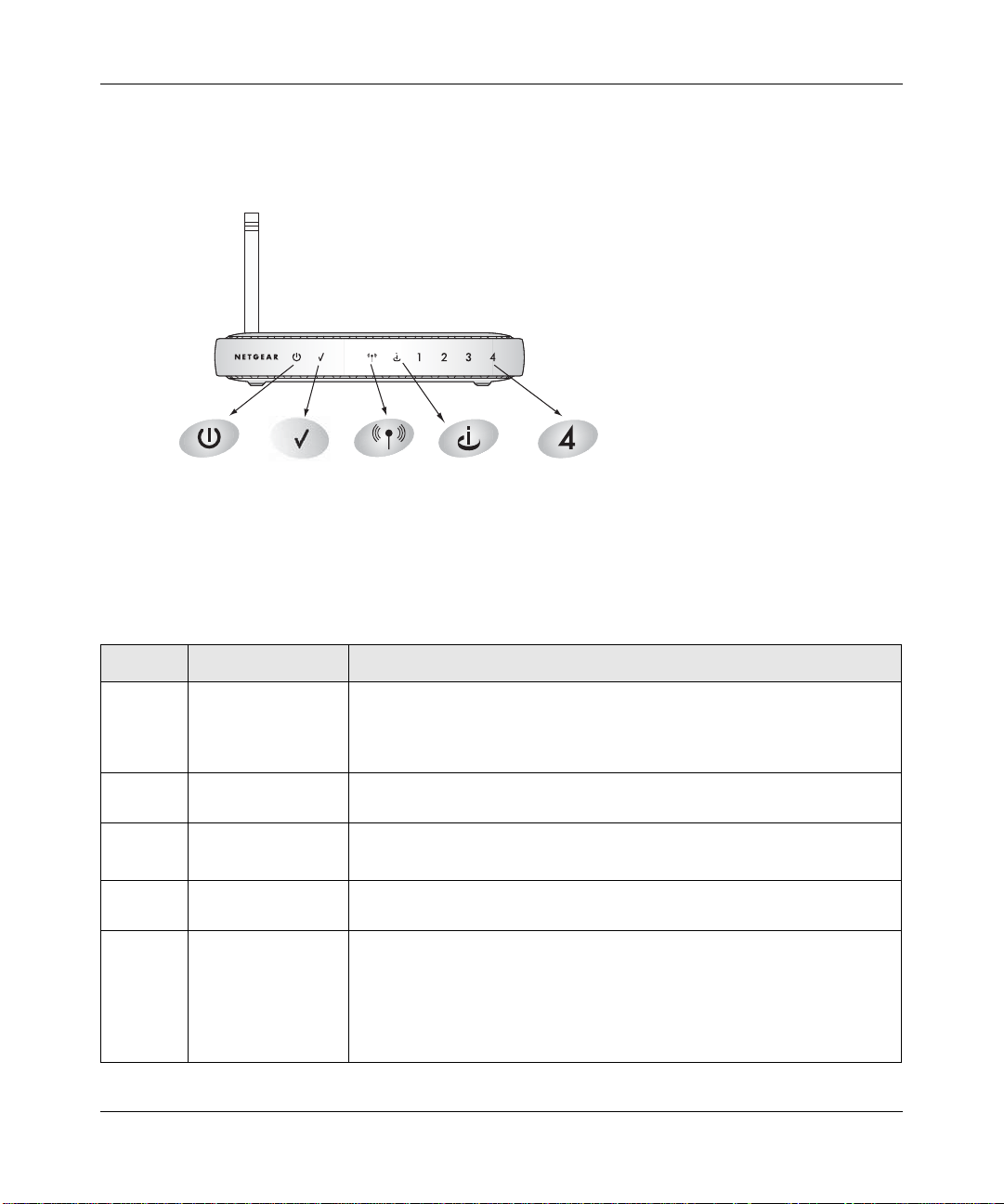
The Router’s Front Panel
The front panel of the WGR614 v6 router contains the status lights described below.
0OWER
4EST
7IRELESS
)NTERNET0ORT
,!.0ORT
Figure 2-1: WGR614 v6 Front Panel
You can use the status lights to verify connections. Viewed from left to right, the table below
describes the lights on the front panel of the router.
Table 2-1. Status Light Descriptions
Label Activity Description
Power On Amber Blinking
On Green Solid
Off
Solid Amber
Test On
Off
Wireless On
Off
Internet On
Blink
LAN On (Green)
Blink (Green)
On (Amber)
Blink (Amber)
Off
Power is supplied to the router and it is performing its diagnostic test.
Power is supplied and the router it has passed its diagnostic test.
Power is not supplied to the router.
The router has failed its diagnostic test.
The unit is performing the power on self test diagnostic.
The unit successfully completed the power on self test diagnostic.
The Wireless port is initialized and the wireless feature is enabled.
The wireless feature is turned off or there is a problem.
The Internet port has detected a link with an attached device.
Data is being transmitted or received by the Internet port.
The LAN (local area network) port has detected link with a 100 Mbps
device.
Data is being transmitted or received at 100 Mbps.
The Local port has detected link with a 10 Mbps device.
Data is being transmitted or received at 10 Mbps.
No link is detected on this port.
2-6 Introduction
202-10099-01, April 2005
Page 21
Reference Manual for the 54 Mbps Wireless Router WGR614 v6
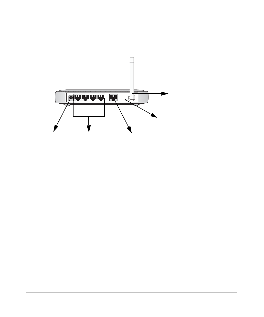
The Router’s Rear Panel
The rear panel of the WGR614 v6 router contains the items listed below.
Wireless
Antenna
1
32
4
Reset
Button
Power
Figure 1-2: WGR614 v6 Rear Panel
4 LAN Ports
Internet Port
Viewed from left to right, the rear panel contains the following features:
• AC power adapter outlet for 12 V DC @ 1A output, 22W maximum
• Four Local (LAN) 10/100 Mbps Ethernet ports for connecting the router to the local
computers
• Internet (WAN) Ethernet port for connecting the router to a cable or DSL modem
• Factory Default Reset push button for Restoring the Default Configuration and Password
• Wireless antenna
Introduction 2-7
202-10099-01, April 2005
Page 22

Reference Manual for the 54 Mbps Wireless Router WGR6 14 v6
2-8 Introduction
202-10099-01, April 2005
Page 23
Chapter 3
Configuring the Internet and Wireless Settings
This chapter describes how to use the Smart Wizard Installation Assistant on the Resource CD to
configure your wireless router’s Internet connection and wireless parameters.
Once you are connected to the Internet and your wireless connections are working, you can also
configure the router’s content filtering parameters if you need to change the default settings. See
Chapter 4, “Content Filtering.
If you are an advanced user, you can also configure maintenance (see Chapter 5, “Maintenance)
and advanced (see Chapter 6, “Advanced Configuration of the Router) settings if you need to
change the factory defaults.
Note: Do not change your existing Internet connection. Instead, let the Smart Wizard
Installation Assistant on the Resource CD guide you through the setup process.
Configuring the Internet and Wireless Settings 3-1
202-10099-01, April 2005
Page 24
Reference Manual for the 54 Mbps Wireless Router WGR6 14 v6
Initial Configuration
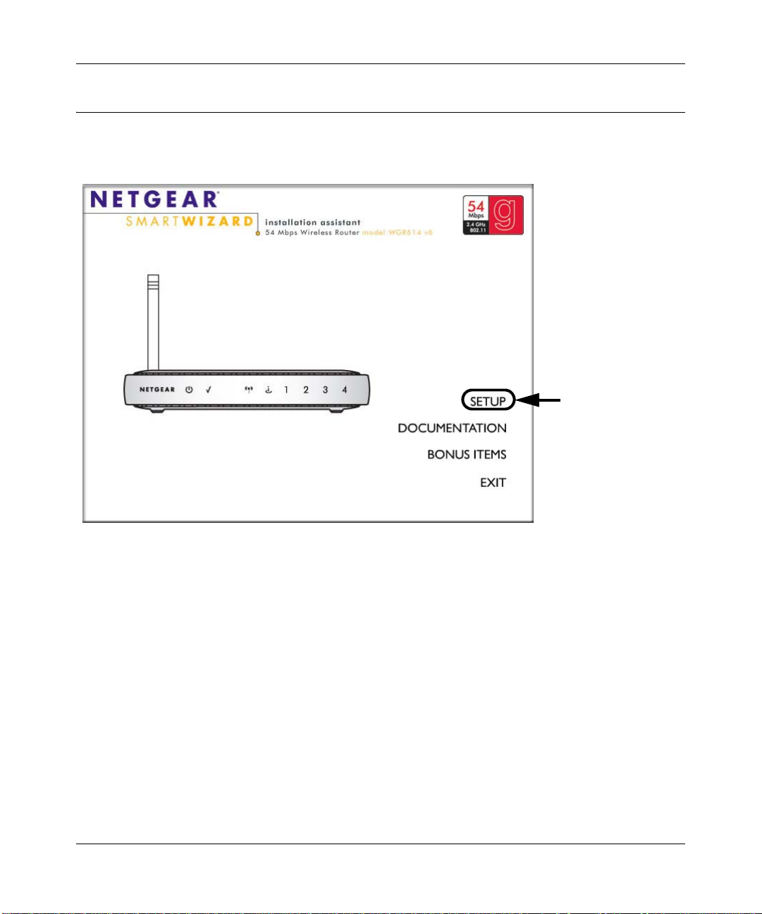
1. Insert the Resource CD into the CD drive on your PC. The following screen appears:
Click SETUP
to get started
Figure 3-1: Smart Wizard Inst allation Assistant Startup screen
Click Setup and follow the instructions. The Smart Wizard Installation Assistant will guide
2.
you through the setup process:
• How to change your cabling.
• How to connect to the Internet.
• How to configure your wireless settings.
– When you get to the wireless settings, you will have to select the country where you
are located and decide whether you want to have security on your wireless links
(Netgear strongly recommends enabling security).
– Depending on the type of security you select, you will also have to enter security key
or passphrase information (see “Wireless Settings” on page 3-9 for information on the
wireless authentication and encryption parameters).
3-2 Configuring the Internet and Wireless Settings
202-10099-01, April 2005
Page 25
Reference Manual for the 54 Mbps Wireless Router WGR614 v6
If you want to change your Internet or wireless settings later, see “Changing Your
Configuration” on page 3-5.
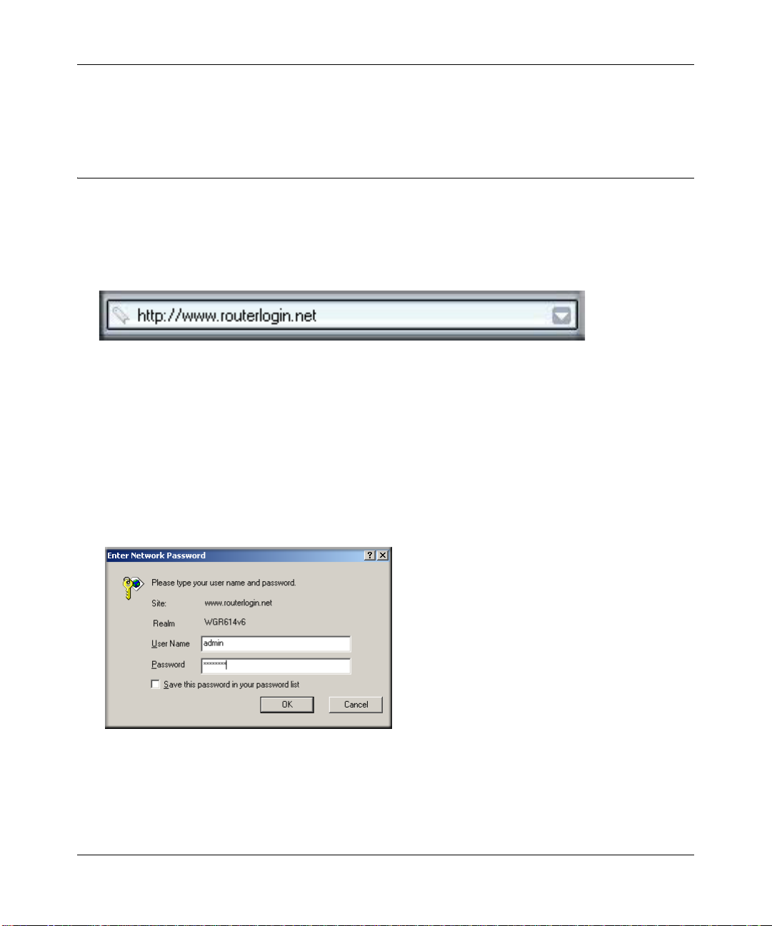
Logging Into Your Router
To log into your router after you have configured your router, do the following:
1. Type http://www.routerlogin.net in the address field of Internet Explorer or Netscape®
Navigator.
Figure 3-2: Log in to the router
2.
When prompted, enter admin for the router user name and password for the router password,
both in lower case letters (or enter the password you chose if you changed it during the setup
in “Initial Configuration” on page 3-2).
Note: The router user name and password are not the same as any user name or password you
may use to log in to your Internet connection.
A login window like the one shown below opens:
Figure 3-3: Login window
Configuring the Internet and Wireless Settings 3-3
202-10099-01, April 2005
Page 26
Reference Manual for the 54 Mbps Wireless Router WGR6 14 v6
Click OK and the resulting window below appears:
3.
Figure 3-4: Login result
3-4 Configuring the Internet and Wireless Settings
202-10099-01, April 2005
Page 27
Reference Manual for the 54 Mbps Wireless Router WGR614 v6
Changing Your Configuration
You can change your Internet and wireless settings after they have been configured by the Smart
Wizard Configuration Assistant.
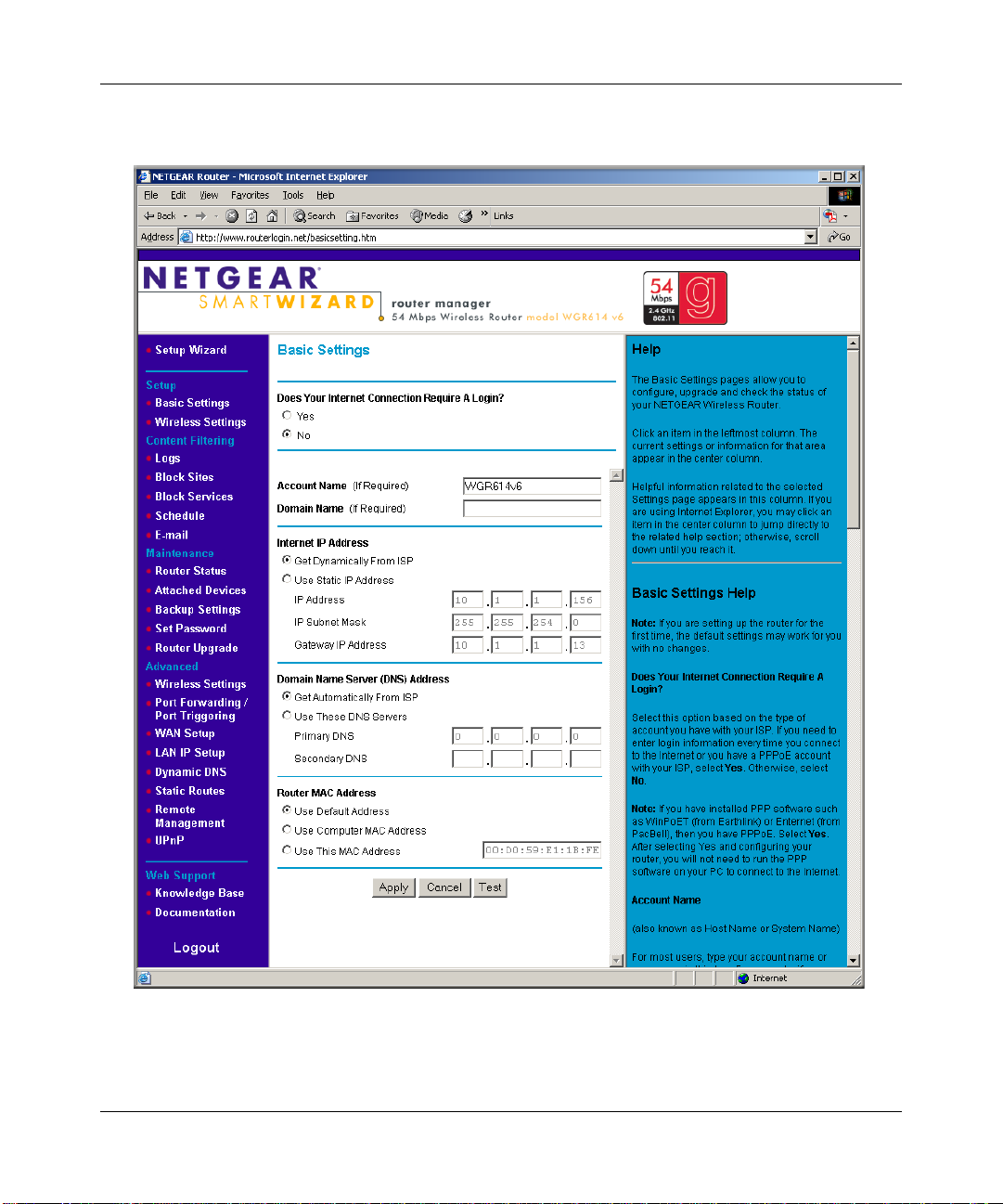
Internet Settings
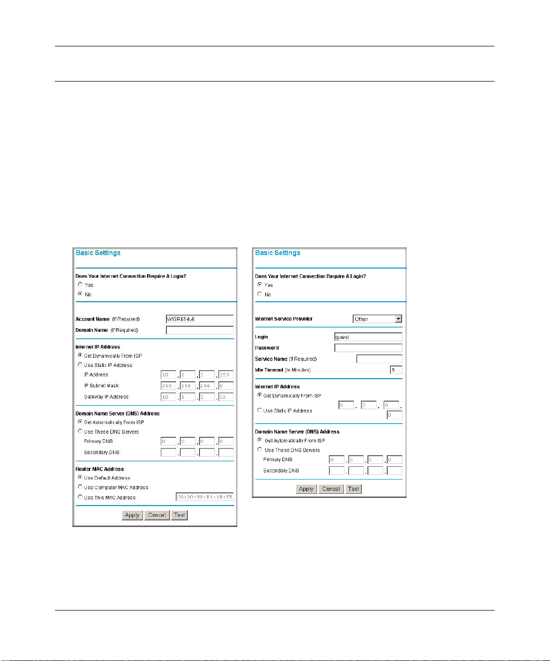
To change the Internet settings, click Basic Settings on the left menu bar. One of the following
screens appears:
Basic Settings, No Login Basic Settings, Login Required
Figure 3-5: Basic Settings screens
The Basic Settings pages allow you to configure, upgrade and check the status of your NETGEAR
Wireless Router.
Configuring the Internet and Wireless Settings 3-5
202-10099-01, April 2005
Page 28

Reference Manual for the 54 Mbps Wireless Router WGR6 14 v6
Click an item in the leftmost column. The current settings or information for that area appear in the
center column.
Helpful information related to the selected Settings page appears in this column. If you are using
Internet Explorer, you may click an item in the center column to jump directly to the related help
section; otherwise, scroll down until you reach it.
For the most current documentation, go to:
http://kbserver.netgear.com/products_automatic/WGR614v6.asp
Note: If you are setting up the router for the first time, the default settings may work for you with
no changes.
• Does Your Internet Connection Require A Login?: Select this option based on the type of
account you have with your ISP. If you need to enter login information every time you connect
to the Internet or you have a PPPoE account with your ISP, select Yes. Otherwise, select No.
Note: If you have installed PPP software such as WinPoET (from Earthlink) or Enternet (from
PacBell), then you have PPPoE. Select Yes. After selecting Yes and configuring your router,
you will not need to run the PPP software on your PC to connect to the Internet.
• Internet Service Provider : Select the service provided by your ISP. "Other" (PPPoE) is the
most common. "PPTP" is used in Austria and other European countries. "Telstra BigPond" is
for Australia only.
– Login: This is usually the name that you use in your e-mail address. For example, if your
main mail account is JerAB@ISP.com, then put JerAB in this box.
Some ISPs (like Mindspring, Earthlink, and T-DSL) require that you use your full e-mail
address when you log in. If your ISP requires your full e-mail address, then type it in the
Login box.
– Password: Type the password that you use to log in to your ISP.
– Service Name: If your ISP provided a Service Name, enter it here. Otherwise, this may be
left blank.
– Idle Timeout: An idle Internet connection will be terminated after this time period.
If this value is zero (0), then the connection will be "kept alive" by re-connecting
immediately whenever the connection is lost.
• Internet IP Address: If you log in to your service or your ISP did not provide you with a
fixed IP address, the router will find an IP address for you automatically when you connect.
Select Get dynamically from ISP.
3-6 Configuring the Internet and Wireless Settings
202-10099-01, April 2005
Page 29

Reference Manual for the 54 Mbps Wireless Router WGR614 v6
If you have a fixed (static, permanent) IP address, your ISP will have provided you with an IP
address. Select Use static IP address and type in the IP Address.
• Account Name (also known as Host Name or System Name): For most users, type your
account name or user name in this box. For example, if your main mail account is
JerAB@ISP.com, then put JerAB in this box.
If your ISP has given you a specific Host name, then type it (for example, CCA7324-A).
• Domain Name: For most users, you may leave this box blank, unless required by your ISP.
You may type the domain name of your ISP. For example, if your ISP's mail server is
mail.xxx.yyy.zzz, you would type xxx.yyy.zzz as the Domain Name.
If you have a Domain name given to you by your ISP, type it in this box. (For ex ample,
Earthlink Cable may require a Host name of 'home' and Comcast sometimes supplies a
Domain name.)
If you have a cable modem, this is usually the Workgroup name.
• Internet IP Address: If you log in to your service or your ISP did not provide you with a
fixed IP address, the router will find an IP address for you automatically when you connect.
Select Get Dynamically From ISP.
If you have a fixed (or static IP) address, your ISP will have provided you with the required
information. Select Use Static IP Address and type the IP Address, Subnet Mask and Gateway
IP Address into the correct boxes.
For example:
IP Address: 24.218.156.183
Subnet Mask: 255.255.255.0
Gateway IP Address: 24.218.156.1
• Domain Name Server (DNS) Address: The DNS server is used to look up site addresses
based on their names.
If your ISP gave you one or two DNS addresses, select Use These DNS Servers and type the
primary and secondary addresses.
Otherwise, select Get Automatically From ISP.
Note: If you get 'Address not found' errors when you go to a Web site, it is likely that your
DNS servers aren't set up properly. You should contact your ISP to get DNS server addresses.
• Router MAC Address: Your computer's local address is its unique address on your network.
This is also referred to as the computer's MAC (Media Access Control) address.
Configuring the Internet and Wireless Settings 3-7
202-10099-01, April 2005
Page 30

Reference Manual for the 54 Mbps Wireless Router WGR6 14 v6
Usually, select Use Default MAC Address.
If your ISP requires MAC authentication, then select either Use Computer MAC address to
disguise the Router's MAC address with the Computer's own MAC address or Use This MAC
Address to manually type the MAC address for a different computer . The format for the MAC
address is XX:XX:XX:XX:XX:XX. This value may be changed if the Use Computer MAC
Address is selected once a value has already been set in the Use This MAC Address selection.
Click Test to connect to the NETGEAR Web site. If you connect successfully, your settings work
and you may click Logout to exit these pages and... enjoy surfing the 'net!
If you don't connect successfully,
1. Go through the settings and make sure you've selected the correct options and typed
everything correctly.
2. Contact your ISP to verify the configuration information.
3. Read the Troubleshooti ng section in the Router Installation Guide.
4. On the Router GearBox CD, read the Troubleshooting Guide or the T roubleshooting section in
the Reference Manual.
5. Contact NETGEAR Technical Support.
3-8 Configuring the Internet and Wireless Settings
202-10099-01, April 2005
Page 31
Reference Manual for the 54 Mbps Wireless Router WGR614 v6
Wireless Settings
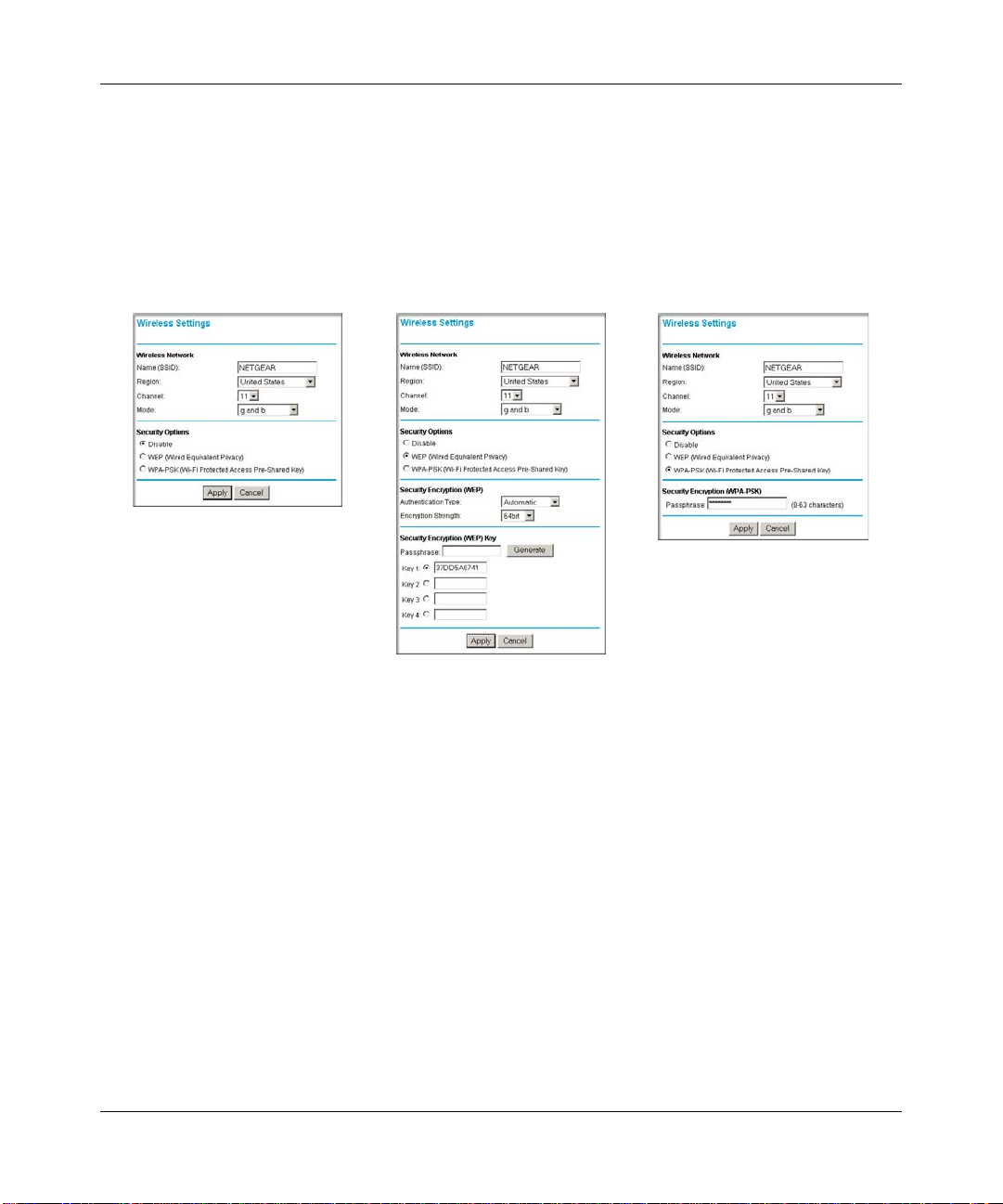
To change the Internet settings, click Wireless Settings on the left menu bar. One of the following
screens appears:
Wireless Settings:
No security
Figure 3-6: Wireless Settings screens
Wireless Settings:
WEP security
Wireless Settings:
WPA-PSK security
NOTE: To ensure proper agency compliance and compatibility between similar products in your
area; the operating channel & region must be set correctly.
• Placement of the Router to Optimize Wireless Connectivity: The operating distance or
range of your wireless connection can vary significantly based on the physical placement of
the router. For best results, place your router:
– Near the center of the area in which your PCs will operate
– In an elevated location such as a high shelf
– Away from potential sources of interference, such as PCs, micr owaves, and cordless
phones
– With the Antenna tight and in the upright position
– Away from large metal surfaces
Configuring the Internet and Wireless Settings 3-9
202-10099-01, April 2005
Page 32

Reference Manual for the 54 Mbps Wireless Router WGR6 14 v6
Note: Failure to follow these guidelines can result in significant performance degradation or
inability to wirelessly connect to the router.
• Name (SSID): Enter a value of up to 32 alphanumeric characters. The same Name (SSID)
must be assigned to all wireless devices in your network. The default SSID is NETGEAR, but
NETGEAR strongly recommends that you change your network's Name (SSID) to a different
value. This value is also case-sensitive. For example, NETGEAR is not the same as
NETGEAr.
• Region: Select your region from the drop-down list. This field displays the region of operation
for which the wireless interface is intended. It may not be legal to operate the router in a region
other than the region shown here. If your country or region is not listed, please check with
your local government agency or check our web site for more information on which channels
to use.
• Channel: This field determines which operating frequency will be used. It should not be
necessary to change the wireless channel unless you notice interference problems with another
nearby access point.
• Mode: Select the desired wireless mode. The options are:
– g & b: Both 802.11g and 802.11b wireless stations can be used.
– g only: Only 802.11g wireless stations can be used.
– b only: All 802.11b wireless stations can be used. 802.11g wireless stations can still be
used if they can operate in 802.11b mode.
The default is "g & b", which allows both "g" and "b" wireless stations to access this device.
• Security Options
– Disable: no data encryption
– WEP (Wired Equivalent Privacy): use WEP 64 or 128 bit data encryption
• Authentication T ype: Normally this can be left at the default value of "Automatic." If
that fails, select the appropriate value - "Open System" or "Shared Key" Check your
wireless card's documentation to see what method to use.
• Encryption Strength: Select the WEP Encryption level:
64-bit (sometimes called 40-bit) encryption
128-bit encryption
• Security Encryption (WEP) Key: If WEP is enabled, you can manually or
automatically program the four data encryption keys. These values must be identical
on all PCs and Access Points in your network.
3-10 Configuring the Internet and Wireless Settings
202-10099-01, April 2005
Page 33

Reference Manual for the 54 Mbps Wireless Router WGR614 v6
• Automatic Key Generation (Passphrase): Enter a word or group of printable
characters in the Passphrase box and click the Generate button to automatically
configure the WEP Key(s). If encryption strength is set to 64 bit, then each of the four
key boxes will automatically be populated with key values. If encryption strength is
set to 128 bit, then only the selected WEP key box will automatically be populated
with key values.
• Manual Entry Mode: Select which of the four keys will be used and enter the
matching WEP key information for your network in the selected key box.
For 64 bit WEP: Enter ten hexadecimal digits (any combination of 0-9, A-F).
For 128 bit WEP: Enter twenty-six hexadecimal digits (any combination of 0-9, A-F).
– WPA-PSK (Wi-Fi Protected Access Pre-Shared Key): use WPA-PSK standard
encryption
• Security Encryption (WPA-PSK) : Enter a word or group of printable characters in
the Passphrase box. The Passphrase must be 8 to 63 characters in length.
Default Factory Settings
When you first receive your WGR614 v6, the default factory settings are shown below. You can
restore these defaults with the Factory Default Restore button on the rear panel. After you install
the WGR614 v6 router, use the procedures below to customize any of the settings to better meet
your networking needs.
FEATURE DEFAULT FACTORY SETTINGS
Wireless Access Point Enabled
Wireless Access List (MAC Filtering) All wireless stations allowed
SSID broadcast Enabled
SSID NETGEAR
11b/g RF Channel 11
Mode g and b
Authentication Type Open System
WEP Disabled
Configuring the Internet and Wireless Settings 3- 11
202-10099-01, April 2005
Page 34

Reference Manual for the 54 Mbps Wireless Router WGR6 14 v6
How to Bypass the Configuration Assistant
1. When the wireless router is in the factory default state, type
http://www.routerlogin.net/basicsetting.htm in the address field of your browser, then click
Enter.
When the wireless router is in the factory default state, a user name and password are not
required.
2. The browser will then display the WGR614 v6 settings home page shown in Figure 3-4.
If you do not click Logout, the wireless router will wait 5 minutes after there is no activity
before it automatically logs you out.
NETGEAR Product Registration, Support, and Documentation
Register your product at http://www.NETGEAR.com/register. Registration is required before
you can use our telephone support service.
Product updates and Web support are always available by going to:
http://kbserver.netgear.com/products/WGR614v6.asp.
Documentation is available on the CD and at
http://kbserver.netgear.com/documentation/WGR614v6.asp.
When the wireless router is connected to the Internet, click the Knowledge Base or the
Documentation link under the Web Support menu to view support information or the
documentation for the wireless router.
3-12 Configuring the Internet and Wireless Settings
202-10099-01, April 2005
Page 35

Chapter 4
Content Filtering
This chapter describes how to use the content filtering features of the 54 Mbps Wireless Router
WGR614 v6 to protect your network. These features can be found by clicking on the Content
Filtering heading in the Main Menu of the browser interface.
Content Filtering Overview
The 54 Mbps Wireless Router WGR614 v6 provides you with Web content filtering options, plus
browsing activity reporting and instant alerts via e-mail. Parents and network administrators can
establish restricted access policies based on time of day, Web addresses and Web address
keywords. You can also block Internet access by applications and services, such as chat or games.
To configure these features of your router, click on the subheadings under the Content Filtering
heading in the Main Menu of the browser interface. The subheadings are described below:
Content Filtering 4-1
202-10099-01, April 2005
Page 36

Reference Manual for the 54 Mbps Wireless Router WGR6 14 v6
Blocking Access to Internet Sites
The WGR614 v6 router allows you to restrict access based on Web addresses and Web address
keywords. Up to 255 entries are supported in the Keyword list. The Block Sites menu is shown in
Figure 4-1 below:
Figure 4-1: Block Sites menu
To enable keyword blocking, select either “Per Schedule” or “Always”, then click Apply. If you
want to block by schedule, be sure that a time period is specified in the Schedule menu.
To add a keyword or domain, type it in the Keyword box, click Add Keyword, then click Apply.
To delete a keyword or domain, select it from the list, click Delete Keyword, then click Apply.
Keyword application examples:
• If the keyword “XXX” is specified, the URL <http://www .badstuff.com/xxx.html> is blocked.
4-2 Content Filtering
202-10099-01, April 2005
Page 37

Reference Manual for the 54 Mbps Wireless Router WGR614 v6
• If the keyword “.com” is specified, only Web sites with other domain suffixes (such as .edu or
.gov) can be viewed.
• If you wish to block all Internet browsing access during a scheduled period , enter the keyword
“.” and set the schedule in the Schedule menu.
To spec ify a Trusted User, enter that PC’s IP address in the Trusted User box and click Apply.
You may specify one Trusted User, which is a PC that will be exempt from blocking and
logging. Since the Trusted User will be identified by an IP address, you should configure that
PC with a fixed IP address.
Blocking Access to Internet Services
The WGR614 v6 router allows you to block the use of certain Internet services by PCs on your
network. This is called services blocking or port filtering. The Block Services menu is shown
below:
Figure 4-2: Block Services menu
Services are functions performed by server computers at the request of client computers. For
example, Web servers serve Web pages, time servers serve time and date information, and game
hosts serve data about other players’ moves. When a computer on your network sends a request for
service to a server computer on the Internet, the requested service is identified by a service or port
number. This number appears as the destination port number in the transmitted IP packets. For
example, a packet that is sent with destination port number 80 is an HTTP (Web server) request.
To enable service blocking, select either Per Schedule or Always, then click Apply. If you want to
block by schedule, be sure that a time period is specified in the Schedule menu.
Content Filtering 4-3
202-10099-01, April 2005
Page 38
Reference Manual for the 54 Mbps Wireless Router WGR6 14 v6
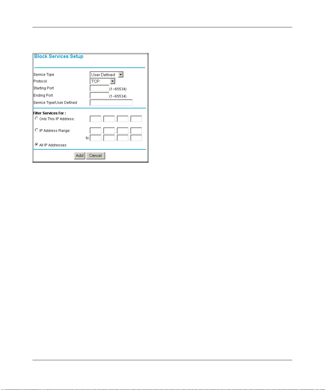
T o specify a service for blocking, click Add. The Add Services menu will appear, as shown below:
Figure 4-3: Add Services menu
From the Service Type list, select the application or service to be allowed or blocked. The list
already displays several common services, but you are not limited to these choices. To add any
additional services or applications that do not already appear, select User Defined.
Configuring a User Defined Service
To define a service, first you must determine which port number or range of numbers is used by
the application. The service numbers for many common protocols are defined by the Internet
Engineering Task Force (IETF) and published in RFC1700, “Assigned Numbers.” Service
numbers for other applications are typically chosen from the range 1024 to 65535 by the authors of
the application. This information can usually be determined by contacting the publisher of the
application or from user groups of newsgroups.
Enter the Starting Port and Ending Port numbers. If the applicatio n uses a single port number , enter
that number in both boxes.
If you know that the application uses either TCP or UDP , select the appropriate protocol. If you are
not sure, select Both.
4-4 Content Filtering
202-10099-01, April 2005
Page 39

Reference Manual for the 54 Mbps Wireless Router WGR614 v6
Configuring Services Blocking by IP Address Range
Under “Filter Services For”, you can block the specified service for a single computer, a range of
computers (having consecutive IP addresses), or all computers on your network.
Scheduling When Blocking Will Be Enforced
The WGR614 v6 router allows you to specify when blocking will be enforced. The Schedule menu
is shown below:
Figure 4-4: Schedule menu
• Use this schedule for blocking content. Check this box if you wish to enable a schedule for
Content Filtering. Click Apply .
• Days to Block. Select days to block by checking the appropriate boxes. Select Everyday to
check the boxes for all days. Click Apply.
• Time of Day to Block. Select a start and end time in 23:59 format. Select All day for 24 hour
blocking. Click Apply.
Be sure to select your Time Zone in the E-Mail menu.
Content Filtering 4-5
202-10099-01, April 2005
Page 40

Reference Manual for the 54 Mbps Wireless Router WGR6 14 v6
Viewing Logs of Web Access or Attempted Web Access
The log is a detailed record of what W eb sites you have accessed or attempted to access. Up to 128
entries are stored in the log. Log entries will only appear when keyword blocking is enabled, an d
no log entries will be made for the Trusted User. An example is shown below:
Figure 4-5: Logs menu
Log entries are described in Table 4-1
Table 4-1. Log entry descriptions
Field Description
Number The index number of the content filter log entries. 128 entries
are available numbered from 0 to 127. The log will keep the
record of the latest 128 entries.
Date and Time The date and time the log entry was recorded.
Source IP The IP address of the initiating device for this log entry.
Action This field displays whether the access was blocked or allowed.
The name or IP address of the Web site or newsgroup visited or
attempted to access.
4-6 Content Filtering
202-10099-01, April 2005
Page 41

Reference Manual for the 54 Mbps Wireless Router WGR614 v6
Log action buttons are described in Table 4-2
Table 4-2. Log action buttons
Field Description
Refresh Click this button to refresh the log screen.
Clear Log Click this button to clear the log entries.
Send Log Click this button to E-mail the log immediately.
Configuring E-Mail Alert and Web Access Log Notifications
In order to receive logs and alerts by E-mail, you must provide your E-mail information in the
E-Mail menu, shown below:
Figure 4-6: Email menu
Content Filtering 4-7
202-10099-01, April 2005
Page 42

Reference Manual for the 54 Mbps Wireless Router WGR6 14 v6
• Turn e-mail notification on
Check this box if you wish to receive e-mail logs and alerts from the router.
• Your outgoing mail server
Enter the name of your ISP’s outgoing (SMTP) mail server (such as mail.myISP.com). You
may be able to find this information in the configuration menu of your e-mail program. If you
leave this box blank, log and alert messages will not be sent via e-mail.
• Send to this e-mail address
Enter the e-mail address to which logs and alerts are sent. This e-mail address will also be used
as the From address. If you leave this box blank, log and alert messages will not be sent via
e-mail.
You can specify that logs are automatically sent to the specified e-mail address with these options:
• Send alert immediately
Check this box if you would like immediate notification of attempted access to a blocked site.
• Send logs according to this schedule
Specifies how often to send the logs: Hourly, Daily, Weekly, or When Full.
– Day for sending log
Specifies which day of the week to send the log. Relevant when the log is sent weekly or
daily.
– Time for sending log
Specifies the time of day to send the log. Relevant when the log is sent daily or weekly.
If the Weekly, Daily or Hourly option is selected and the log fills up before the specified
period, the log is automatically e-mailed to the specified e-mail address. After the log is sent,
the log is cleared from the router’s memory. If the router cannot e-mail the log file, the log
buffer may fill up. In this case, the router overwrites the log and discards its contents.
The WGR614 v6 router uses the Network Time Protocol (NTP) to obtain the current time and date
from one of several Network Time Servers on the Internet. In order to localize the time for your
log entries, you must specify your Time Zone:
•Time Zone
Select your local time zone. This setting will be used for the blocking schedule and for
time-stamping log entries.
• Daylight Savings Time
Check this box if your time zone is currently under daylight savings time.
4-8 Content Filtering
202-10099-01, April 2005
Page 43

Chapter 5
Maintenance
This chapter describes how to use the maintenance features of your 54 Mbps Wireless Router
WGR614 v6. These features can be found by clicking on the Maintenance heading in the Main
Menu of the browser interface.
Viewing Wireless Router Status Information
The Router Status menu provides status and usage information. From the Main Menu of the
browser interface, click on Maintenance, then select Router Status to view the System Status
screen, shown below.
Figure 5-1: Router Status screen
Maintenance 5-1
202-10099-01, April 2005
Page 44

Reference Manual for the 54 Mbps Wireless Router WGR6 14 v6
This screen shows the following parameters:
Table 5-1. Wireless Router Status Fields
Field Description
Account Name This field displays the Host Name assigned to the router.
Firmware Version This field displays the router firmware version.
Internet Port These parameters apply to the Internet (WAN) port of the router.
MAC Address This field displays the Media Access Control address being used by the
Internet (WAN) port of the router.
IP Address This field displays the IP address being used by the Internet (WAN) port
of the router. If no address is shown, the router cannot connect to the
Internet.
DHCP If set to None, the router is configured to use a fixed IP address on the
WAN.
If set to Client, the router is configured to obtain an IP address
dynamically from the ISP.
IP Subnet Mask This field displays the IP Subnet Mask being used by the Internet (WAN)
port of the router.
DNS This field displays the Domain Name Server addresses being used by
the router.
LAN Port These parameters apply to the Local (LAN) port of the router.
MAC Address This field displays the Media Access Control address being used by the
LAN port of the router.
IP Address This field displays the IP address being used by the Local (LAN) port of
the router. The default is 192.168.1.1
IP Subnet Mask This field displays the IP Subnet Mask being used by the Local (LAN)
port of the router. The default is 255.255.255.0
DHCP Identifies if the router’s built-in DHCP server is active for the LAN
attached devices.
5-2 Maintenance
202-10099-01, April 2005
Page 45
Reference Manual for the 54 Mbps Wireless Router WGR614 v6
Table 5-1. Wireless Router Status Fields (continued)
Field Description
Wireless Port These parameters apply to the Wireless port of the router.
MAC Address This field displays the Media Access Control address being used by the
Wireless port of the router.
Name (SSID) This field displays the wireless network name (SSID) being used by the
wireless port of the router. The default is NETGEAR.
Region This field displays the geographic region where the router being used. It
may be illegal to use the wireless features of the router in some parts of
the world.
Channel Identifies the channel of the wireless port being used. See “Wireless
Channels” on page D-7 for the frequencies used on each channel.
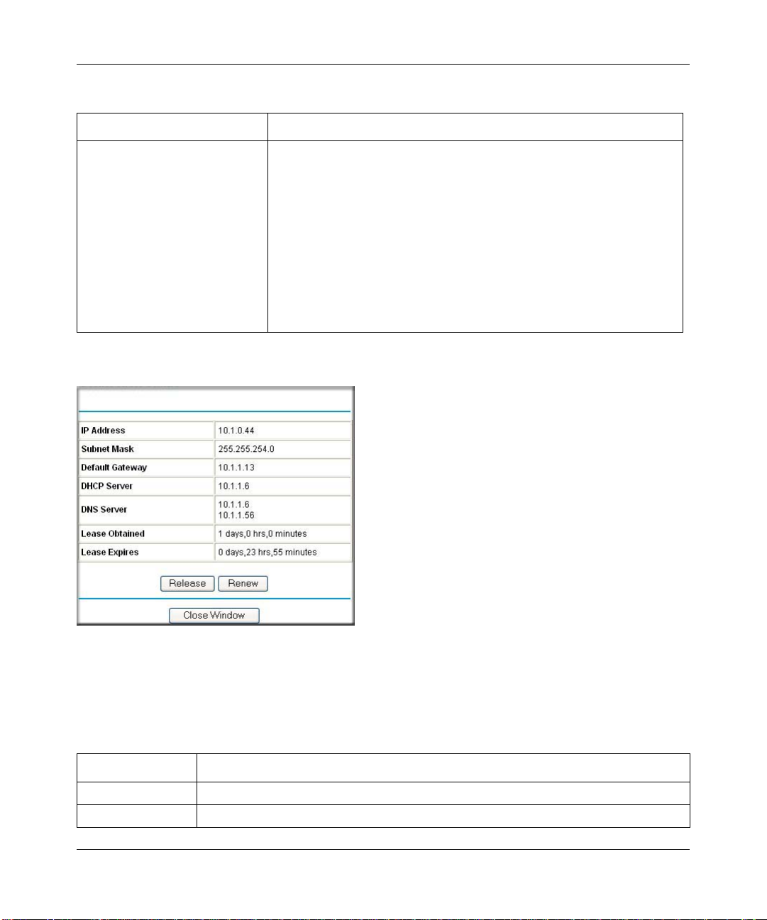
Click on the “Connection Status” button to display the connection status, as shown below.
Figure 5-2: Connection Status screen
This screen shows the following statistics:.
Table 5-2: Connection Status Items
Item Description
IP Address The WAN (Internet) IP Address assigned to the router.
Subnet Mask The WAN (Internet) Subnet Mask assigned to the router.
Maintenance 5-3
202-10099-01, April 2005
Page 46

Reference Manual for the 54 Mbps Wireless Router WGR6 14 v6
Table 5-2: Connection Status Items (continued)
Item Description
Default Gateway The WAN (Internet) default gateway the router communicates with.
DHCP Server The IP address of the DHCP server which provided the IP configuration addresses.
DNS Server The IP address of the DNS server which provides network name to IP address
translation.
Lease Obtained When the DHCP lease was obtained.
Lease Expires When the DHCP lease was expires.
Release Click the Release button to release the DHCP lease.
Renew Click the Renew button to renew the DHCP lease.
Click on the “Show Statistics” button to display router usage statistics, as shown below.
Figure 5-3: Router Statistics screen
This screen shows the following statistics:
Table 5-3: Router Statistics Items
Item Description
Port The statistics for the WAN (Internet) and LAN (local) ports. For each port, the screen
displays:
Status The link status of the port.
TxPkts The number of packets transmitted on this port since reset or manual clear.
RxPkts The number of packets received on this port since reset or manual clear.
Collisions The number of collisions on this port since reset or manual clear.
Tx B/s The current transmission (outbound) bandwidth used on the WAN and LAN ports.
5-4 Maintenance
202-10099-01, April 2005
Page 47
Reference Manual for the 54 Mbps Wireless Router WGR614 v6
Table 5-3: Router Statistics Items (continued)
Item Description
Rx B/s The current reception (inbound) bandwidth used on the WAN and LAN ports.
Up Time The amount of time since the router was last restarted.
Up Time The time elapsed since this port acquired the link.
Poll Interval Specifies the intervals at which the statistics are updated in this window. Click on Stop
to freeze the display.
Set Interval Enter a time and click the button to set the polling frequency.
Stop Click the Stop button to freeze the polling information.
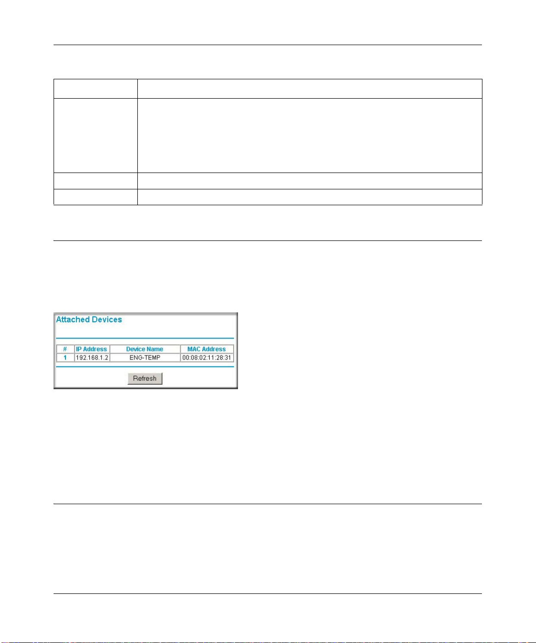
Viewing a List of Attached Devices
The Attached Devices menu contains a table of all IP devices that the router has discovered on the
local network. From the Main Menu of the browser interface, under the Maintenance heading,
select Attached Devices to view the table, shown below.
Figure 5-4: Attached Devices menu
For each device, the table shows the IP address, NetBIOS Host Name (if available), and Ethernet
MAC address. Note that if the router is rebooted, the table data is lost until the router rediscovers
the devices. To force the router to look for attached devices, click the Refresh button.
Configuration File Management
The configuration settings of the WGR614 v6 router are stored within the router in a configuration
file. This file can be saved (backed up) to a user’s PC, retrieved (restored) from the user’s PC, or
cleared to factory default settings.
Maintenance 5-5
202-10099-01, April 2005
Page 48

Reference Manual for the 54 Mbps Wireless Router WGR6 14 v6
From the Main Menu of the browser interface, under the Maintenance heading, select the Settings
Backup heading to bring up the menu shown below.
Figure 5-5: Settings Backup menu
Three options are available, and are described in the following sections.
Restoring and Backing Up the Configuration
The Restore and Backup options in the Settings Backup menu allow you to save and retrieve a file
containing your router’s configuration settings.
To save your settings, click the Backup button. Your browser will extract the configuration file
from the router and will prompt you for a location on your PC to store the file. You can give the
file a meaningful name at this time, such as pacbell.cfg.
T o restore your settings from a saved configuration file, enter the full path to the file on your PC or
click the Browse button to browse to the file. When you have located it, click the Restore button to
send the file to the router. The router will then reboot automatically.
Warning: Do not interrupt the reboot process.
5-6 Maintenance
202-10099-01, April 2005
Page 49

Reference Manual for the 54 Mbps Wireless Router WGR614 v6
Erasing the Configuration
It is sometimes desirable to restore the router to original default settings. This can be done by using
the Erase function, which will restore all factory settings. After an erase, the router's password will
be password, the LAN IP address will be 192.168.1.1, and the router's DHCP client will be
enabled.
To era se the configuration, click the Erase button.
To restore the factory default configuration settings without knowing the login password or IP
address, you must use the Default Reset button on the rear panel of the router. See “Restoring the
Default Configuration and Password” on page 7-7.
Upgrading the Router Software
Note: Before upgrading the router software, use the router backup utility to save your
configuration settings. Any router upgrade will revert the router settings back to the
factory defaults. After completing the upgrade, you can restore your settings from the
backup.
The routing software of the WGR614 v6 router is stored in FLASH memory, and can be upgraded
as new software is released by NETGEAR. Upgrade files can be downloaded from the NETGEAR
W eb site. If the upgrade file is compressed (.ZIP file ), you must first extract the file before sending
it to the router. The upgrade file can be sent to the router using your browser.
Note: The Web browser used to upload new firmware into the WGR614 v6 router must support
HTTP uploads. NETGEAR recommends using Microsoft Internet Explorer 5.0 and above and
Netscape Navigator 4.7 and above.
From the Main Menu of the browser interface, under the Maintenance heading, select the Router
Upgrade link display the menu shown below.
Maintenance 5-7
202-10099-01, April 2005
Page 50

Reference Manual for the 54 Mbps Wireless Router WGR6 14 v6
Figure 5-6: Router Upgrade menu
To upload new firmware:
1. Download and unzip (if the downloaded file is a .zip file) the new software file from
NETGEAR.
2. In the Router Upgrade menu, click the Browse button and browse to the location of the
upgrade file
3. Click Upload.
Note: When uploading software to the WGR614 v6 router, it is important not to interrupt the
Web browser b y clo sing the window, clicking a link, or loading a new page. If the browser is
interrupted, it may corrupt the software. When the upload is complete, your router will
automatically restart. The upgrade process will typically take about one minute.
In some cases, you may need to reconfigure the router after upgrading.
Changing the Administrator Password
Note: Before changing the router password, use the router backup utility to save your
configuration settings. If after changing the password, you forget the new password you
assigned, you will have to reset the router back to the factory defaults to be able to log in
using the default password of password. This means you will have to restore all the
router configuration settings. If you ever have to reset the router back to the factory
defaults, you can restore your settings from the backup.
The default password for the router’s Web Configuration Manager is password. NETGEAR
recommends that you change this password to a more secure password.
5-8 Maintenance
202-10099-01, April 2005
Page 51
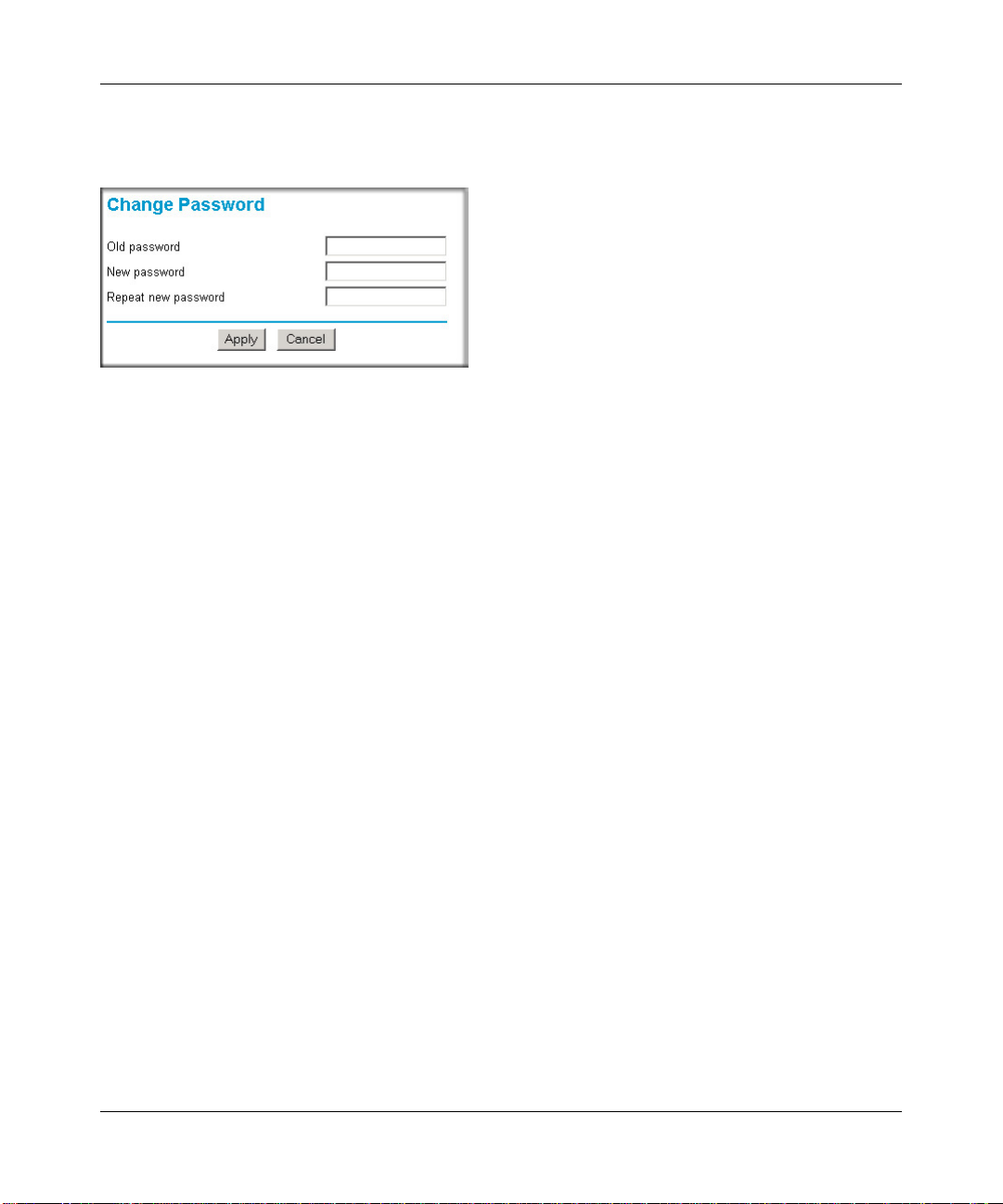
Reference Manual for the 54 Mbps Wireless Router WGR614 v6
From the Main Menu of the browser interface, under the Maintenance heading, select Set
Password to bring up the menu shown below.
Figure 5-7: Set Password menu
To change the password, first enter the old password, then enter the new password twice. Click
Apply.
Maintenance 5-9
202-10099-01, April 2005
Page 52

Reference Manual for the 54 Mbps Wireless Router WGR6 14 v6
5-10 Maintenance
202-10099-01, April 2005
Page 53

Chapter 6
Advanced Configuration of the Router
This chapter describes how to configure the advanced features of your 54 Mbps Wireless Router
WGR614 v6. These features can be found under the Advanced heading in the Main Menu of the
browser interface.
.
Note: If you are unfamiliar with networking and routing, refer to Appendix B,
“Network, Routing, Firewall, and Basics,” to become more familiar with the terms and
procedures used in this chapter.
Configuring Port Triggering
Port Triggering is an advanced feature that can be used to easily enable gaming and other internet
applications. Port Forwarding is typically used to enable similar functionality, but it is static and
has some limitations.
Note: If you use applications such as multi-player gaming, peer-to-peer connections, real time
communications such as instant messaging, or remote assistance (a feature in Windows XP), you
should also enable UPnP according to the instructions at “Using Universal Plug and Play (UPnP)“
on page 6-18.
Port Triggering opens an incoming port temporarily and does not require the server on the internet
to track your IP address if it is changed by DHCP, for example.
Port Triggering monitors outbo und traffic. When the router detects traffic on the specified
outbound port, it remembers the IP address of the computer that sent the data and triggers the
incoming port. Incoming traffic on the triggered port is then forwarded to the triggering computer.
Using the Port Triggering page, you can make local computers or servers available to the Internet
for different services (for example, FTP or HTTP), to play Internet games (like Quake III), or to
use Internet applications (like CUseeMe).
Port Forwarding is designed for FTP, Web Server or other server based services. Once port
forwarding is set up, request from Internet will be forwarded to the proper server. On the contrary,
Advanced Configuration of the Router 6-1
202-10099-01, April 2005
Page 54

Reference Manual for the 54 Mbps Wireless Router WGR6 14 v6
port triggering will only allow request from Internet after a designated port is 'triggered'. Port
triggering applies to chat and Internet games.
Figure 6-1: Port Triggering Menu
Note: If Disable Port Triggering box is checked after configuring port triggering, port triggering
will be disabled but any port triggering configuration information you added to the router will be
retained even though it will not be used.
• Port Triggering Timeout
Enter a value up to 9999 minutes. The Port Triggering Timeout value controls the inactivity
timer for the designated inbound port(s). The inbound port(s) will be closed when the
inactivity timer expires.
• For Internet Games or Applications
Before starting, you'll need to know which service, application or game you'll be configuring.
Also, you'll need to have the outbound port (triggering port) address for this game or
application.
6-2 Advanced Configuration of the Router
202-10099-01, April 2005
Page 55

Reference Manual for the 54 Mbps Wireless Router WGR614 v6
Follow these steps to set up a computer to play Internet games or use Internet applications:
1. Click Add.
Figure 6-2: Add Port Tr igger Menu
2.
Enter a service name in the Service Name box.
3. Under Service User, selecting Any (default) will allow this service to be used by everyone in
your network. Otherwise, select Single address and enter the IP address of one computer to
restrict the service to a particular computer.
4. Select the Service Type.
5. Enter the outbound port number in Triggering Port box.
6. Enter the inbound connection port information such as Connection Type, Starting Port and
Ending Port boxes. This information can be obtained from the game or applications manual or
support Web site.
7. Click Apply to save your changes.
Configuring Port Forwarding to Local Servers
Although the router causes your entire local network to appear as a single machine to the Internet,
you can make a local server (for example, a W eb server or game server) visible and available to the
Internet. This is done using the Port Forwarding menu. From the Main Menu of the browser
Advanced Configuration of the Router 6-3
202-10099-01, April 2005
Page 56

Reference Manual for the 54 Mbps Wireless Router WGR6 14 v6
interface, under Advanced, click on Port Forwarding to view the port forwarding menu, shown
below.
Figure 6-3: Port Forwarding Menu
Use the Port Forwarding menu to configure the router to forward incoming protocols to computers
on your local network. In addition to servers for specific applications, you can also specify a
Default DMZ Server to which all other incoming protocols are forwarded. The DMZ Server is
configured in the WAN Setup menu as discussed in “Configuring the WAN Setup Options“ on
page 6-7.
Before starting, you'll need to determine which type of service, application or game you'll provide
and the IP address of the computer that will provide each service. Be sure the computer’s IP
address never changes. To configure port forwarding to a local server:
Note: To assure that the same computer always has the same IP address, use the reserved
IP address feature of your WGR614 v6 router. See “Using Address Reservation“ on page
6-12 for instructions on how to use reserved IP addresses.
1. From the Service & Game box, select the service or game that you will host on your network.
If the service does not appear in the list, refer to the following section, “Adding a Custom
Service”.
2. Enter the IP address of the local server in the corresponding Server IP Address box.
3. Click the Add button.
6-4 Advanced Configuration of the Router
202-10099-01, April 2005
Page 57
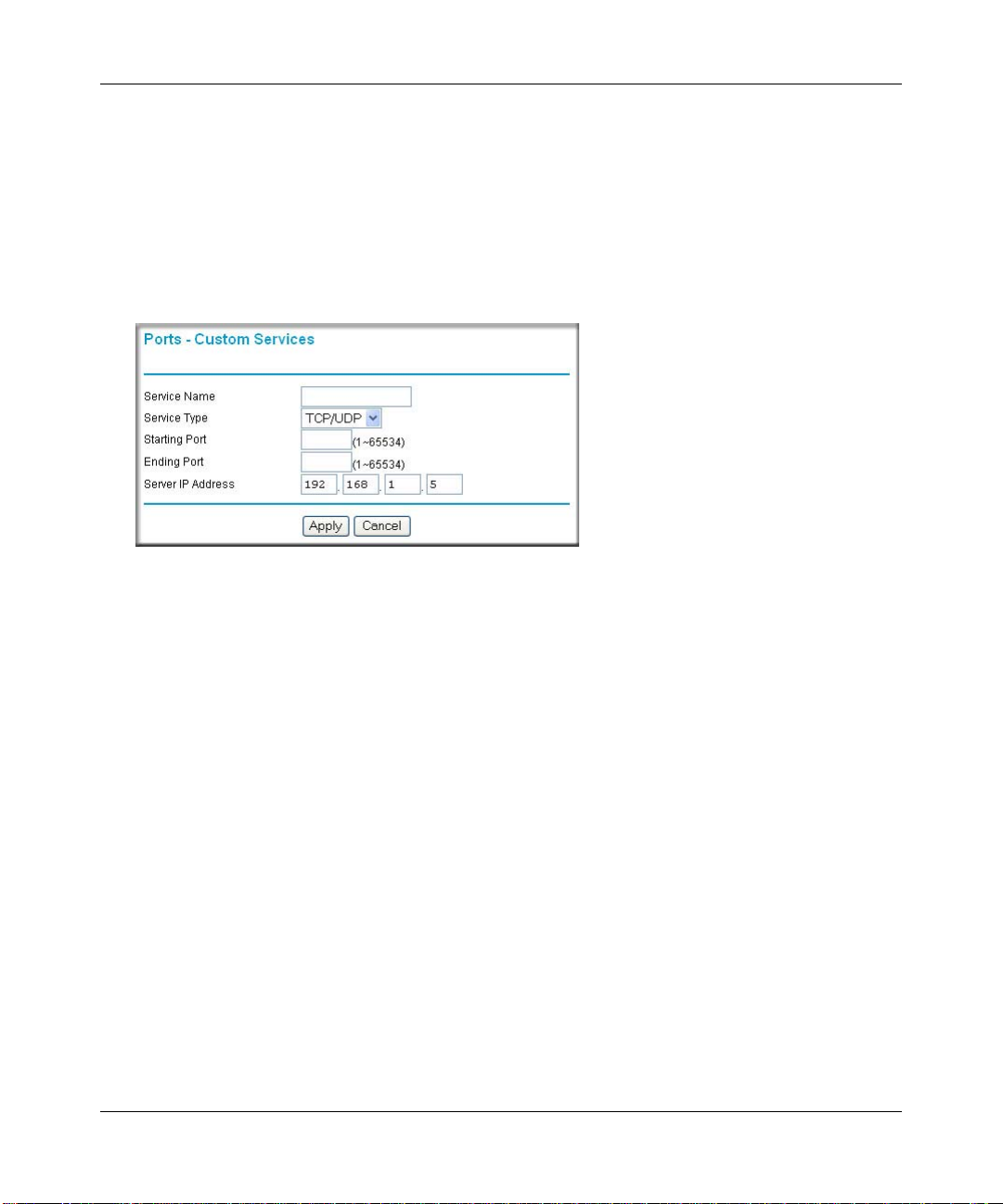
Reference Manual for the 54 Mbps Wireless Router WGR614 v6
Adding a Custom Service
To define a service, game or application that does not appear in the Services & Games list, you
must determine what port numbers are used by the service. For this information, you may need to
contact the manufacturer of the program that you wish to use. When you have the port number
information, follow these steps:
1. Click the Add Custom Service button.
Figure 6-4: Ports - Custom Services Menu
2.
Type the service name in the Service Name box.
3. Type the beginning port number in the Starting Port box.
• If the application uses only a single port; type the same port number in the Ending Port
box.
• If the application uses a range of ports; type the ending port number of the range in the
Ending Port box.
4. Type the IP address of the computer in the Server IP Address box.
5. Click Apply to save your changes.
Editing or Deleting a Port Forwarding Entry
To edit or delete a Port Forw arding entry, follow these steps.
1. In the table, select the button next to the service name.
2. Click Edit or Delete.
Advanced Configuration of the Router 6-5
202-10099-01, April 2005
Page 58

Reference Manual for the 54 Mbps Wireless Router WGR6 14 v6
Local Web and FTP Server Example
If a local computer with a private IP address of 192.168.1.33 acts as a Web and FTP server,
configure the Ports menu to forward HTTP (port 80) and FTP (port 21) to local address
192.168.1.33
In order for a remote user to access this server from the Internet, the remote user must know the IP
address that has been assigned by your ISP. If this address is 172.16.1.23, for example, an Internet
user can access your Web server by directing the browser to http://172.16.1.23. The assigned IP
address can be found in the Maintenance Status Menu, where it is shown as the WAN IP Address.
Some considerations for this application are:
• If your account’s IP address is assigned dynamically by your ISP, the IP address may change
periodically as the DHCP lease expires.
• If the IP address of the local computer is assigned by DHCP , it may change when the computer
is rebooted. To avoid this, you can manually configure the computer to use a fixed address.
• Local computers must access the local server using the computers’ local LAN address
(192.168.1.33 in this example). Attempts by local computers to access the server using the
external IP address (172.16.1.23 in this example) will fail.
Multiple Computers for Half Life, KALI or Quake III Example
To set up an additional computer to play Half Life, KALI or Quake III:
1. Click the button of an unused port in the table.
2. Select the game again from the Services/Games list.
3. Change the beginning port number in the Start Port box.
For these games, use the supplied number in the default listing and add +1 for each additional
computer. For example, if you've already configured one computer to play Hexen II (using
port 26900), the second computer's port number would be 26901, and the third computer
would be 26902.
4. Type the same port number in the End Port box that you typed in the Start Port box.
5. Type the IP address of the additional computer in the Server IP Address box.
6. Click Apply.
6-6 Advanced Configuration of the Router
202-10099-01, April 2005
Page 59

Reference Manual for the 54 Mbps Wireless Router WGR614 v6
Some online games and videoconferencing applications are incompatible with NAT . The WGR614
v6 router is programmed to recognize some of these applications and to work properly with them,
but there are other applications that may not function well. In some cases, one local computer can
run the application properly if that computer’s IP address is entered as the default in the PORTS
Menu. If one local computer acts as a game or videoconferencing host, enter its IP address as the
default.
Configuring the WAN Setup Options
The WAN Setup options let you configure a DMZ server, change the MTU size and enable the
wireless router to respond to a Ping on the WAN port. These options are discussed below.
Figure 6-5: WAN Setup menu.
Connect Automatically, as Required
Normally, this option should be checked to enable it. An Internet connection will be made
automatically after each timeout, whenever Internet-bound traffic is detected. This provides
connection on demand and is potentially cost-saving in places in Europe for example where
Internet services charge by the minute.
If disabled, you must connect manually, using the “Connection Status” button on the Router Status
screen. This manual connection will stay up all the time without time outs.
Advanced Configuration of the Router 6-7
202-10099-01, April 2005
Page 60
Reference Manual for the 54 Mbps Wireless Router WGR6 14 v6
Disabling the SPI Firewall
The SPI (Stateful Packet Inspection) Firewall protects your LAN against Denial of Service attacks.
This should only be disabled in special circumstances.
Setting Up a Default DMZ Server
The default DMZ server feature is helpful when using some online games and videoconferencin g
applications that are incompatible with NAT. The router is programmed to recognize some of these
applications and to work properly with them, but there are other applications that may not function
well. In some cases, one local computer can run the application properly if that computer’s IP
address is entered as the default DMZ server.
Note: DMZ servers pose a security risk. A computer designated as the default DMZ
server loses much of the protection of the firewall, and is exposed to exploits from the
Internet. If compromised, the DMZ server can be used to attack your network.
Incoming traffic from the Internet is normally discarded by the router unless the traffic is a
response to one of your local computers or a service that you have configured in the Ports menu.
Instead of discarding this traffic, you can have it forwarded to one computer on your network. This
computer is called the Default DMZ Server.
The WAN Setup menu, shown below lets you configure a Default DMZ Server.
To as sign a computer or server to be a Default DMZ server, follow these steps:
1. Click WAN Setup link on the Advanced section of the main menu.
2. Type the IP address for that server. To remove the default DMZ server, replace the IP address
numbers with all zeros.
3. Click Apply.
Responding to Ping on Internet WAN Port
If you want the router to respond to a 'ping' from the Internet, click the ‘Respond to Ping on
Internet WAN Port’ check box. This should only be used as a diagnostic tool, since it allows your
router to be discovered. Don't check this box unless you have a specific reason to do so.
6-8 Advanced Configuration of the Router
202-10099-01, April 2005
Page 61
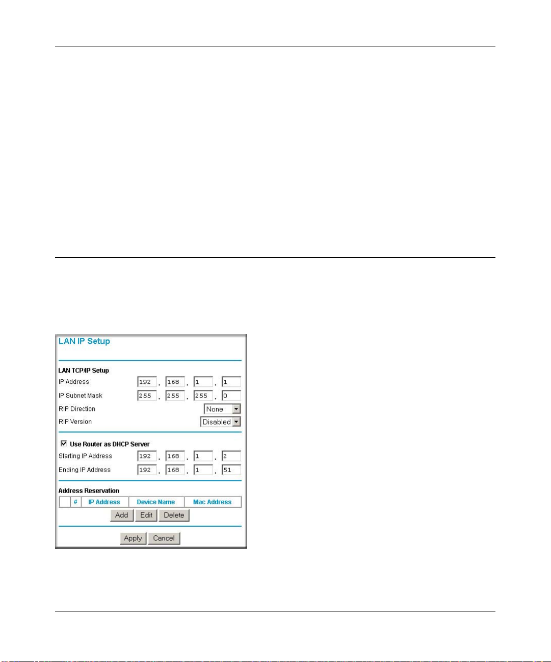
Reference Manual for the 54 Mbps Wireless Router WGR614 v6
Setting the MTU Size
The normal MTU (Maximum Transmit Unit) value for most Ethernet networks is 1500 Bytes,
1492 Bytes for PPPoE connections, or 1436 for PP TP connections. For some ISPs you may need to
reduce the MTU. But this is rarely required, and should not be done unless you are sure it is
necessary for your ISP connection.
Any packets sent through the router that are larger than the configured MTU size will be
repackaged into smaller packets to meet the MTU requirement. To change the MTU size:
1. Under MTU Size, enter a new size between 64 and 1500.
2. Click Apply to save the new configuration.
Using the LAN IP Setup Options
The second feature category under the Advanced heading is LAN IP Setup. This menu allows
configuration of LAN IP services such as DHCP and RIP. From the Main Menu of the browser
interface, under Advanced, click on LAN IP Setup to view the LAN IP Setup menu, shown below.
Figure 6-6: LAN IP Setup Menu
Advanced Configuration of the Router 6-9
202-10099-01, April 2005
Page 62

Reference Manual for the 54 Mbps Wireless Router WGR6 14 v6
Configuring LAN TCP/IP Setup Parameters
The router is shipped preconfigured to use private IP addresses on the LAN side, and to act.as a
DHCP server. The router’s default LAN IP configuration is:
• LAN IP addresses—192.168.1.1
• Subnet mask—255.255.255.0
These addresses are part of the IETF-designated private address range for use in private networks,
and should be suitable in most applications. If your network has a requirement to use a different IP
addressing scheme, you can make those changes in this menu.
The LAN IP parameters are:
• IP Address
This is the LAN IP address of the router.
• IP Subnet Mask
This is the LAN Subnet Mask of the router. Combined with the IP address, the IP Subnet Mask
allows a device to know which other addresses are local to it, and which must be reached
through a gateway or router.
• RIP Direction
RIP (Router Information Protocol) allows a router to exchange routing information with other
routers. The RIP Direction selection controls how the router sends and receives RIP packets.
None is the default.
— When set to Both or Out Only, the router will broadcast its routing table periodically.
— When set to Both or In Only, it will incorporate the RIP information that it receives.
— When set to None (default), it will not send any RIP packets and will ignore any RIP
packets received.
• RIP Version
This controls the format and the broadcasting method of the RIP packets that the router sends.
(It recognizes both formats when receiving.) By default, this is set for RIP-1.
— RIP-1 is universally supported. RIP-1 is probably adequate for most networks, unless you
have an unusual network setup.
— RIP-2 carries more information. RIP-2B uses subnet broadcasting.
6-10 Advanced Configuration of the Router
202-10099-01, April 2005
Page 63
Reference Manual for the 54 Mbps Wireless Router WGR614 v6
Note: If you change the LAN IP address of the router while connected through the
browser, you will be disconnected. You must then open a new connection to the new IP
address and log in again.
Using the Router as a DHCP server
By default, the router will function as a DHCP (Dynamic Host Configuration Protocol) server,
allowing it to assign IP, DNS server, and default gateway addresses to all computers connected to
the router's LAN. The assigned default gateway address is the LAN address of the router. IP
addresses will be assigned to the attached computers from a pool of addresses specified in this
menu. Each pool address is tested before it is assigned to avoid duplicate addresses on the LAN.
For most applications, the default DHCP and TCP/IP settings of the router are satisfactory. See “IP
Configuration by DHCP” on page B-10 for an explanation of DHCP and information about how to
assign IP addresses for your network.
If another device on your network will be the DHCP server, or if you will manually configure the
network settings of all of your computers, clear the ‘Use router as DHCP server’ check box.
Otherwise, leave it checked.
Specify the pool of IP addresses to be assigned by setting the Starting IP Address and Ending IP
Address. These addresses should be part of the same IP address subnet as the router’s LAN IP
address. Using the default addressing scheme, you should define a range between 192.168.1.2 and
192.168.1.253, although you may wish to save part of the range for device s with fixed addresses.
The router will deliver the following parameters to any LAN device that requests DHCP:
• An IP Address from the range you have defined
• Subnet Mask
• Gateway IP Address (the router’s LAN IP address)
• Primary DNS Server (if you entered a Primary DNS address in the Basic Settings menu;
otherwise, the router’s LAN IP address)
• Secondary DNS Server (if you entered a Secondary DNS address in the Basic Settings menu
Advanced Configuration of the Router 6-11
202-10099-01, April 2005
Page 64

Reference Manual for the 54 Mbps Wireless Router WGR6 14 v6
Using Address Reservation
When you specify a reserved IP address for a computer on the LAN, that computer will always
receive the same IP address each time it access the router’s DHCP server. Reserved IP addresses
should be assigned to servers that require permanent IP settings.
To res erve an IP address:
1. Click the Add button.
Figure 6-7: Address Reservation menu
2.
In the IP Address box, type the IP address to assign to the computer or server.
(choose an IP address from the router’s LAN subnet, such as 192.168.1.X)
3. Type the MAC Address of the computer or server.
(Tip: If the computer is already present on your network, you can cop y its MAC address from
the Attached Devices menu and paste it here.)
4. Click Apply to enter the reserved address into the table.
Note: The reserved address will not be assigned until the next time the computer contacts the
router's DHCP server. Reboot the computer or access its IP configuration and force a DHCP
release and renew.
To edit or delete a res erved address entry:
1. Click the button next to the reserved address you want to edit or delete.
2. Click Edit or Delete.
6-12 Advanced Configuration of the Router
202-10099-01, April 2005
Page 65
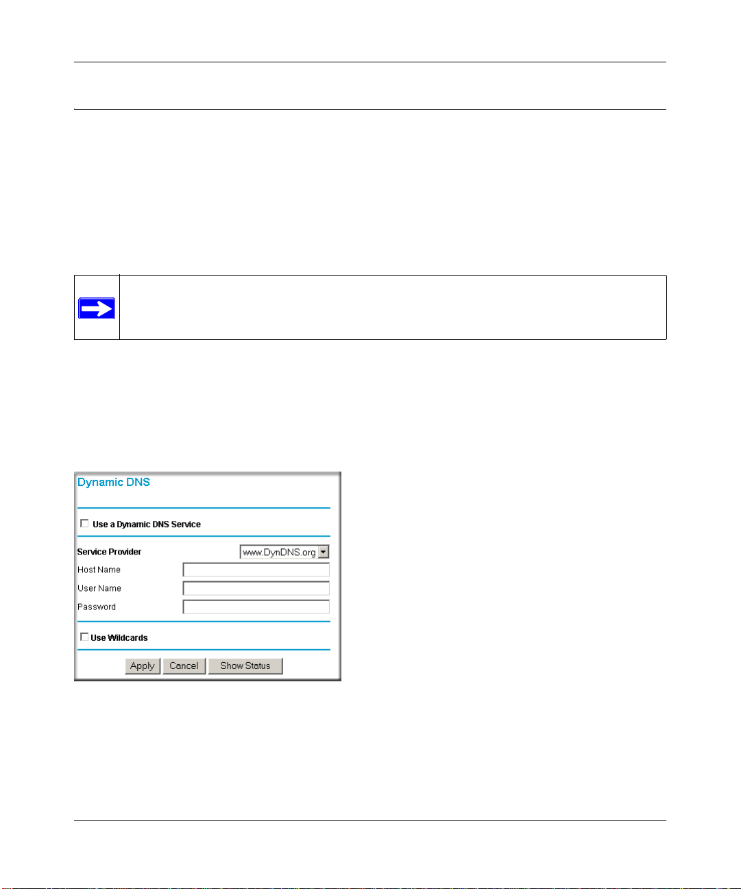
Reference Manual for the 54 Mbps Wireless Router WGR614 v6
Using a Dynamic DNS Service
If your network has a permanently assigned IP address, you can register a domain name and have
that name linked with your IP address by public Domain Name Servers (DNS). However, if your
Internet account uses a dynamically assigned IP address, you will not know in advance what your
IP address will be, and the address can change frequently. In this case, you can use a commercial
dynamic DNS service, who will allow you to register your domain to their IP address, and will
forward traffic directed at your domain to your frequently-changing IP address.
Note: If your ISP assigns a private WAN IP address (such as 192.168.x.x or 10.x.x.x),
the dynamic DNS service will not work because private addresses will not be routed on
the Internet.
The router contains a client that can connect to many popular dynamic DNS services. You can
select one of these services and obtain an account with them. Then, whenever your ISP-assigned
IP address changes, your router will automatically contact your dynamic DNS service provider,
log in to your account, and register your new IP address.
From the Main Menu of the browser interface, under Advanced, click on Dynamic DNS.
Figure 6-8: Dynamic DNS menu
To configure Dynamic DNS:
1. Register for an account with one of the dynamic DNS service providers whose names appear
in the ‘Select Service Provider’ box. For example, for dyndns.org, go to www.dyndns.org.
Advanced Configuration of the Router 6-13
202-10099-01, April 2005
Page 66

Reference Manual for the 54 Mbps Wireless Router WGR6 14 v6
Select the Use a dynamic DNS service check box.
2.
3. Select the name of your dynamic DNS Service Provider.
4. Type the Host Name (or domain name) that your dynamic DNS service provider gave you.
5. Type the User Na me for your dynamic DNS account.
6. Type the Password (or key) for your dynamic DNS account.
7. If your dynamic DNS provider allows the use of wildcards in resolving your URL, you may
select the Use wildcards check box to activate this feature.
For example, the wildcard feature will cause *.yourhost.dyndns.org to be aliased to the same
IP address as yourhost.dyndns.org
8. Click Apply to save your configuration.
Configuring Static Routes
Static Routes provide additional routing information to your router. Under normal circumstances,
the router has adequate routing information after it has been configured for Internet access, and
you do not need to configure additional static routes. You must configure static routes only for
unusual cases such as multiple routers or multiple IP subnets located on your network.
From the Main Menu of the browser interface, under Advanced, click on Static Routes to view the
Static Route menu, shown below.
Figure 6-9. Static Route Summary Table
6-14 Advanced Configuration of the Router
202-10099-01, April 2005
Page 67

Reference Manual for the 54 Mbps Wireless Router WGR614 v6
To add or edit a Static Route:
1. Click the Add button to open the Add/Edit Menu, shown below.
Figure 6-10. Static Route Entry and Edit Menu
2.
Type a route name for this static route in the Route Name box under the table.
(This is for identification purposes only.)
3. Select Private if you want to limit access to the LAN only. The static route will not be reported
in RIP.
4. Select Active to make this route effective.
5. Type the Destination IP Address of the final destination.
6. Type the IP Subnet Mask for this destination.
If the destination is a single host, type 255.255.255.255.
7. T ype the Gateway IP Address, which must be a router on the same LAN segment as the router.
8. Type a number between 1 and 15 as the Metric value.
This represents the number of routers between your network and the destination. Usually, a
setting of 2 or 3 works, but if this is a direct connection, set it to 1.
9. Click Apply to have the static route entered into the table.
As an example of when a static route is needed, consider the following case:
• Your primary Internet access is thro ugh a cable modem to an ISP.
• You have an ISDN router on your home network for connecting to the company where
you are employed. This router’s address on your LAN is 192.168.1.100.
• Your company’s network is 134.177.0.0.
Advanced Configuration of the Router 6-15
202-10099-01, April 2005
Page 68

Reference Manual for the 54 Mbps Wireless Router WGR6 14 v6
When you first configured your router, two implicit static routes were created. A default route was
created with your ISP as the gateway, and a second static route was created to your local network
for all 192.168.1.x addresses. With this configuration, if you attempt to access a device on the
134.177.0.0 network, your router will forward your request to the ISP. The ISP forwards your
request to the company where you are employed, and the request will likely be denied by the
company’s firewall.
In this case you must define a static route, telling your router that 134.177.0.0 should be accessed
through the ISDN router at 192.168.1.100. The static route would look like Figure 6-10.
In this example:
• The Destination IP Address and IP Subnet Mask fields specify that this static route applies to
all 134.177.x.x addresses.
• The Gateway IP Address fields specifies that all traffic for these addresses should be
forwarded to the ISDN router at 192.168.1.100.
• A Metric value of 1 will work since the ISDN router is on the LAN.
• Private is selected only as a precautionary security measure in case RIP is activated.
Enabling Remote Management Access
Using the Remote Management page, you can allow a user or users on the Internet to configure,
upgrade and check the status of your WGR614 v6 router.
Note: Be sure to change the router's default configuration password to a very secure
password. The ideal password should contain no dictionary words from any language,
and should be a mixture of letters (both upper and lower case), numbers, and symbols.
Your password can be up to 30 characters.
6-16 Advanced Configuration of the Router
202-10099-01, April 2005
Page 69

Reference Manual for the 54 Mbps Wireless Router WGR614 v6
Figure 6-11: Remote Management menu
To configure your router for Remote Management:
1. Select the Turn Remote Management On check box.
2. Specify what external addresses will be allowed to access the router’s remote management.
Note: For enhanced security, restrict access to as few external IP addresses as practical.
a. To allow access from any IP address on the Internet, select Everyone.
b. To allow access from a range of IP addresses on the Internet, select IP address range.
Enter a beginning and ending IP address to define the allowed range.
c. To allow access from a single IP address on the Internet, select Only this computer.
Enter the IP address that will be allowed access.
3. Specify the Port Number that will be used for accessing the management interface.
Web browser access norma lly uses the standard HTTP service port 80. For greater security,
change the remote management Web interface to a custom port by entering that number in the
box provided. Choose a number between 1024 and 65535, but do not use the number of any
common service port. The default is 8080, which is a common alternate for HTTP.
4. Click Apply to have your changes take effect.
Advanced Configuration of the Router 6-17
202-10099-01, April 2005
Page 70

Reference Manual for the 54 Mbps Wireless Router WGR6 14 v6
Note: When accessing your router from the Internet, you will type your router's WAN IP address
into your browser's Address (in IE) or Location (in Netscape) bo x, follo wed by a colo n (:) an d the
custom port number. For example, if your external address is 134.177.0.123 and you use port
number 8080, you must enter http://134.177.0.123:8080 in your browser. The Remote
Management Address from the Remote Management Window (see Figure 6-11) is the address you
will enter in your browser's address field.
Using Universal Plug and Play (UPnP)
Universal Plug and Play (UPnP) helps devices, such as Internet appliances and computers,
access the network and connect to other devices as needed. UPnP devices can
automatically discover the services from other registered UPnP devices on the network.
Figure 6-12. UPnP Menu
From the Main Menu of the browser interface, under Advanced, click on UPnP. Set up UPnP
according to the guidelines below.
Turn UPnP On: UPnP can be enabled or disabled for automatic device configuration. The default
setting for UPnP is disabled. If disabled, the router will not allow any device to automatically
control the resources, such as port forwarding (mapping), of the router.
6-18 Advanced Configuration of the Router
202-10099-01, April 2005
Page 71

Reference Manual for the 54 Mbps Wireless Router WGR614 v6
Note: If you use applications such as multi-player gaming, peer-to-peer connections, real time
communications such as instant messaging, or remote assistance (a feature in Windows XP), you
should enable UPnP.
Advertisement Period: The Advertisement Period is how often the router will broadcast its UPnP
information. This value can range from 1 to 1440 minutes. The default period is 30 minutes.
Shorter durations will ensure that control points have current device status at the expense of
additional network traffic. Longer durations may compromise the freshness of the device status but
can significantly reduce network traffic.
Advertisement Time To Live: The time to live for the advertisement is measured in hops (steps)
for each UPnP packet sent. The time to live hop count is the number of steps a broadcast packet is
allowed to propagate for each UPnP advertisement before it disappears. The number of hops can
range from 1 to 255. The default value for the advertisement time to live is 4 hops, which should
be fine for most home networks. If you notice that some devices are not being updated or reached
correctly, then it may be necessary to increase this value a little.
UPnP Portmap T able: The UPnP Portmap Table displays the IP address of each UPnP device that
is currently accessing the router and which ports (Internal and External) that device has opened.
The UPnP Portmap T able also displays what type of port is opened and if that port is still active for
each IP address.
Advanced Configuration of the Router 6-19
202-10099-01, April 2005
Page 72

Reference Manual for the 54 Mbps Wireless Router WGR6 14 v6
6-20 Advanced Configuration of the Router
202-10099-01, April 2005
Page 73

Chapter 7
Troubleshooting
This chapter gives information about troubleshooting your 54 Mbps Wireless Router WGR614 v6.
After each problem description, instructions are provided to help you diagnose and solve the
problem.
Basic Functioning
After you turn on power to the router, the following sequence of events should occur:
1. When power is first applied, verify that the Power light is on.
2. After approximately 10 seconds, verify that:
a. The power light is solid green.
b. The LAN port lights are lit for any local ports that are connected.
c. The Internet port light is lit.
If a port’s light is lit, a link has been established to the connected device. If a LAN port is
connected to a 100 Mbps device, verify that the port’ s light is green. If the port is 10 Mbps, the
light will be amber.
If any of these conditions does not occur, refer to the appropriate following section.
Power Light Not On
If the Power and other lights are off when your router is turned on:
• Make sure that the power cord is properly connected to your router and that the power supply
adapter is properly connected to a functioning power outlet.
• Check that you are using the 12 V DC 1A power adapter supplied by NETGEAR for this
product.
If the error persists, you have a hardware problem and should contact technical support.
Troubleshooting 7-1
202-10099-01, April 2005
Page 74

Reference Manual for the 54 Mbps Wireless Router WGR6 14 v6
Lights Never Turn Off
When the router is turned on, the lights turns on for about 10 seconds and then turn off. If all the
lights stay on, there is a fault within the router.
If all lights are still on one minute after power up:
• Cycle the power to see if the router recovers.
• Clear the router’s configuration to factory defaults. This will set the router’s IP address to
192.168.1.1. This procedure is explained in “Restoring the Default Configuration and
Password” on page 7-7.
If the error persists, you might have a hardware problem and should contact technical support.
LAN or WAN Port Lights Not On
If either the LAN lights or Internet light do not light when the Ethernet connection is made, check
the following:
• Make sure that the Ethernet cable connections are secure at the router and at the hub or
workstation.
• Make sure that power is turned on to the connected hub or workstation.
• Be sure you are using the correct cable:
— When connecting the router’s Internet port to a cable or DSL modem, use the cable that
was supplied with the cable or DSL modem. This cable could be a standard
straight-through Ethernet cable or an Ethernet crossover cable.
7-2 Troubleshooting
202-10099-01, April 2005
Page 75

Reference Manual for the 54 Mbps Wireless Router WGR614 v6
Troubleshooting the Web Configuration Interface
If you are unable to access the router’s Web Configuration interface from a computer on your local
network, check the following:
• Check the Ethernet connection between the computer and the router as described in the
previous section.
• Make sure your computer’s IP address is on the same subnet as the router. If you are using the
recommended addressing scheme, your computer’s address should be in the range of
192.168.1.2 to 192.168.1.254. Refer to “Verifying TCP/IP Properties” on page C-8 or
“Verifying TCP/IP Properties for Macintosh Computers” on page C-19 to find your
computer’s IP address. Follow the instructions in Appendix C to configure your computer.
Note: If your computer’s IP address is shown as 169.254.x.x: Recent versions of Windows
and MacOS will generate and assign an IP address if the computer cannot reach a DHCP
server. These auto-generated addresses are in the range of 169.254.x.x. If your IP address is in
this range, check the connection from the computer to the router and reboot your computer.
• If your router’s IP address has been changed and you don’t know the current IP address, clear
the router’s configuration to factory defaults. This will set the router’s IP address to
192.168.1.1. This procedure is explained in “Restoring the Default Configuration and
Password” on page 7-7.
• Make sure your browser has Java, JavaScript, or ActiveX enabled. If you are using Internet
Explorer, click Refresh to be sure the Java applet is loaded.
• Try quitting the browser and launching it again.
• Make sure you are using the correct login information. The factory default login name is
admin and the password is password. Make sure that CAPS LOCK is off when entering this
information.
If the router does not save changes you have made in the Web Configuration Interface, check the
following:
• When entering configuration settings, be sure to click the APPLY button before moving to
another menu or tab, or your changes are lost.
• Click the Refresh or Reload button in the Web browser. The changes may have occurred, but
the Web browser may be caching the old configuration.
Troubleshooting 7-3
202-10099-01, April 2005
Page 76

Reference Manual for the 54 Mbps Wireless Router WGR6 14 v6
Troubleshooting the ISP Connection
If your router is unable to access the Internet, you should first determine whether the router is able
to obtain a WAN IP address from the ISP. Unless you have been assigned a static IP address, your
router must request an IP address from the ISP. You can determine whether the request was
successful using the Web Configura t ion Manager.
To check the WAN IP address:
1. Launch your browser and select an external site such as www.netgear.com
2. Access the Main Menu of the router’s configuration at http://www.routerlogin.net.
3. Under the Maintenance heading, select Router Status
4. Check that an IP address is shown for the WAN Port
If 0.0.0.0 is shown, your router has not obtained an IP address from your ISP.
If your router is unable to obtain an IP address from the ISP, you may need to force your cable or
DSL modem to recognize your new router by performing the following procedure:
1. Turn off power to the cable or DSL modem.
2. Turn off power to your router.
3. Wait five minutes and reapply power to the cable or DSL modem.
4. When the modem’s lights indicate that it has reacquired sync with the ISP, reapply power to
your router.
5. Then restart your computer.
If your router is still unable to obtain an IP address from the ISP, the problem may be one of the
following:
• Your ISP may require a login program.
Ask your ISP whether they require PPP over Ethernet (PPPoE) or some other type of login.
• If your ISP requires a login, you may have incorrectly set the login name and password.
• Your ISP may check for your computer's host name.
Assign the computer Host Name of your ISP account as the Account Name in the Basic
Settings menu.
• Your ISP only allows one Ethernet MAC address to connect to Internet, and may check for
your computer’s MAC address. In this case:
7-4 Troubleshooting
202-10099-01, April 2005
Page 77

Reference Manual for the 54 Mbps Wireless Router WGR614 v6
Inform your ISP that you have bought a new network device, and ask them to use the router’s
MAC address.
OR
Configure your router to spoof your computer’s MAC address. This can be done in the Basic
Settings menu.
If your router can obtain an IP address, but your computer is unable to load any Web pages from
the Internet:
• Your computer may not recognize any DNS server addresses.
A DNS server is a host on the Internet that translates Internet names (such as www addresses)
to numeric IP addresses. Typically your ISP will provide the addresses of one or two DNS
servers for your use. If you entered a DNS address during the router’s configuration, reboot
your computer and verify the DNS address as described in “Install or Verify Windows
Networking Components” on page C-9. Alternatively, you may configure your computer
manually with DNS addresses, as explained in your operating system documentation.
• Your computer may not have the router configured as its TCP/IP gateway.
If your computer obtains its information from the router by DHCP, reboot the computer and
verify the gateway address as described in “Install or Verify Windows Networking
Components” on page C-9.
Troubleshooting a TCP/IP Network Using a Ping Utility
Most TCP/IP terminal devices and routers contain a ping utility that sends an echo request packet
to the designated device. The device then responds with an echo reply. Troubleshooting a TCP/IP
network is made very easy by using the ping utility in your computer or workstation.
Testing the LAN Path to Your Router
You can ping the router from your computer to verify that the LAN path to your router is set up
correctly.
To ping the router from a running Windows 95 or later:
1. From the Windows toolbar, click on the Start button and select Run.
2. In the field provided, type Ping followed by the IP address of the router, as in this example:
ping 192.168.1.1
Troubleshooting 7-5
202-10099-01, April 2005
Page 78

Reference Manual for the 54 Mbps Wireless Router WGR6 14 v6
Click on OK.
3.
You should see a message like this one:
Pinging <IP address> with 32 bytes of data
If the path is working, you see this message:
Reply from < IP address >: bytes=32 time=NN ms TTL=xxx
If the path is not working, you see this message:
Request timed out
If the path is not functioning correctly, you could have one of the following problems:
• Wrong physical connections
— Make sure the LAN port LED is on. If the LED is off, follow the instructions in “LAN
or WAN Port Lights Not On” on page 7-2.
— Check that the corresponding Link LEDs are on for your network interface card and
for the hub ports (if any) that are connected to your workstation and router.
• Wrong network configuration
— Verify that the Ethernet card driver software and TCP/IP software are both installed
and configured on your computer or workstation.
— Verify that the IP address for your router and your workstation are correct and that the
addresses are on the same subnet.
Testing the Path from Your Computer to a Remote Device
After verifying that the LAN path works correctly, test the path from your computer to a remote
device. From the Windows run menu, type:
PING -n 10 <IP address>
where <IP address> is the IP address of a remote device such as your ISP’s DNS server.
If the path is functioning correctly, replies as in the previous section are displayed. If you do not
receive replies:
— Check that your computer has the IP address of your router listed as the default gateway. If
the IP configuration of your computer is assigned by DHCP, this information will not be
visible in your computer’s Network Control Panel. Verify that the IP address of the router
is listed as the default gateway as described in “Install or Verify Windows Networking
Components” on page C-9.
7-6 Troubleshooting
202-10099-01, April 2005
Page 79

Reference Manual for the 54 Mbps Wireless Router WGR614 v6
— Check to see that the network address of your computer (the portion of the IP address
specified by the netmask) is different from the network address of the remote device.
— Check that your cable or DSL modem is connected and functioning.
— If your ISP assigned a host name to your computer, enter that host name as the Account
Name in the Basic Settings menu.
— Your ISP could be rejecting the Ethernet MAC addresses of all but one of your computers.
Many broadband ISPs restrict access by only allowing traffic from the MAC address of
your broadband modem, but some ISPs additionally restrict access to the MAC address of
a single computer connected to that modem. If this is the case, you must configure your
router to “clone” or “spoof” the MAC address from the authorized computer.
Restoring the Default Configuration and Password
This section explains how to restore the factory default configuration settings, changing the
router’s administration password to password and the IP address to 192.168.1.1. You can erase the
current configuration and restore factory defaults in two ways:
• Use the Erase function of the router (see “Erasing the Configuration” on page 5-7).
• Use the Default Reset button on the rear panel of the router. Use this method for cases when
the administration password or IP address is not known.
To restore the factory default configuration settings without knowing the administration password
or IP address, you must use the Default Reset button on the rear panel of the router.
1. Press and hold the Default Reset button until the power light blinks on (about 10 seconds).
2. Release the Default Reset button and wait for the router to reboot.
If the wireless router fails to restart or the power light continues to blink or turns solid amber,
the unit may be defective. If the error persists, you might have a hardware problem and should
contact technical support.
Problems with Date and Time
The E-Mail menu in the Content Filtering section displays the current date and time of day. The
WGR614 v6 router uses the Network Time Protocol (NTP) to obtain the current time from one of
several Network Time Servers on the Internet. Each entry in the log is stamped with the date and
time of day. Problems with the date and time function can include:
Troubleshooting 7-7
202-10099-01, April 2005
Page 80

Reference Manual for the 54 Mbps Wireless Router WGR6 14 v6
• Date shown is January 1, 2000. Cause: The router has not yet successfully reached a Network
Time Server. Check that your Internet access settings are configured correctly. If you have just
completed configuring the router , wait at least five minutes and check the date and time again.
• Time is off by one hour. Cause: The router does not automatically sense Daylight Savings
Time. In the E-Mail menu, check or uncheck the box marked “Adjust for Daylight Savings
Time”.
7-8 Troubleshooting
202-10099-01, April 2005
Page 81

Appendix A
Technical Specifications
This appendix provides technical specifications for the 54 Mbps Wireless Router WGR614 v6.
Network Protocol and Standards Compatibility
Data and Routing Protocols: TCP/IP, RIP-1, RIP-2, DHCP
PPP over Ethernet (PPPoE)
Power Adapter
North America: 120V, 60 Hz, input
United Kingdom, Australia: 240V, 50 Hz, input
Europe: 230V, 50 Hz, input
Japan: 100V, 50/60 Hz, input
All regions (output): 12 V DC @ 1A output, 22W maximum
Physical Specifications
Dimensions: 28 x 175 x 119 mm (1.1 x 6.89 x 4.68 in.)
Weight: 0.3 kg (0.66 lb)
Environmental Specifications
Operating temperature: 0° to 40° C (32º to 104º F)
Operating humidity: 90% maximum relative humidity, noncondensing
Electromagnetic Emissions
Meets requirements of: FCC Part 15 Class B
VCCI Class B
EN 55 022 (CISPR 22), Class B
C-Tick N10947
Interface Specifications
LAN: 10BASE-T or 100BASE-Tx, RJ-45
WAN: 10BASE-T or 100BASE-Tx, RJ-45
Technical Specifications A-1
202-10099-01, April 2005
Page 82

Reference Manual for the 54 Mbps Wireless Router WGR6 14 v6
Wireless
Radio Data Rates 1, 2, 5.5, 6, 9, 12, 18, 24, 36, 48, and 54 Mbps
Auto Rate Sensing
Frequency 2.4-2.5Ghz
Data Encoding: 802.11b: Direct Sequence Spread Spectrum (DSSS)
802.11g: Orthogonal Frequency Division Multiplexing (OFDM)
Maximum Computers Per Wireless
Network:
Operating Frequency Ranges: 2.412~2.462 GHz (US) 2.457~2.462 GHz (Spain)
802.11 Security: 40-bits (also called 64-bits) and 128-bits WEP and WPA-PSK
Limited by the amount of wireless network traffic generated by each
node. Typically 30-70 nodes.
2.412~2.484 GHz (Japan)2.457~2.472 GHz (France)
2.412~2.472 GHz (Europe ETSI)
A-2 Technical Specifications
202-10099-01, April 2005
Page 83

Appendix B
Network, Routing, Firewall, and Basics
This chapter provides an overview of IP networks, routing, and networking.
Related Publications
As you read this document, you may be directed to various RFC documents for further
information. An RFC is a Request For Comment (RFC) published by the Internet Engineering
T ask Force (IETF), an open organization that defines the architecture and operation of the Internet.
The RFC documents outline and define the standard protocols and procedures for the Internet. The
documents are listed on the World Wide Web at www.ietf.org and are mirrored and indexed at
many other sites worldwide.
Basic Router Concepts
Large amounts of bandwidth can be provided easily and relatively inexpensively in a local area
network (LAN). However, providing high bandwidth between a local network and the Internet can
be very expensive. Because of this expense, Internet access is usually provided by a slower-speed
wide-area network (WAN) link such as a cable or DSL modem. In order to make the best use of the
slower WAN link, a mechanism must be in place for selecting and transmitting only the data traffic
meant for the Internet. The function of selecting and forwarding this data is performed by a router.
What is a Router?
A router is a device that forwards traffic between networks based on network layer information in
the data and on routing tables maintained by the router. In these routing tables, a router builds up a
logical picture of the overall network by gathering and exchanging information with other routers
in the network. Using this information, the router chooses the best path for forwarding network
traffic.
Routers vary in performance and scale, number of routing protocols supported, and types of
physical WAN connection they support. The 54 Mbps Wireless Router WGR614 v6 is a small
office router that routes the IP protocol over a single-user broadband connection.
Network, Routing, Firewall, and Basics B-1
202-10099-01, April 2005
Page 84

Reference Manual for the 54 Mbps Wireless Router WGR6 14 v6
Routing Information Protocol
One of the protocols used by a router to build and maintain a picture of the network is the Routing
Information Protocol (RIP). Using RIP, routers periodically update one another and check for
changes to add to the routing table.
The WGR614 v6 router supports both the older RIP-1 and the newer RIP-2 protocols. Among
other improvements, RIP-2 supports subnet and multicast protocols. RIP is not required for most
home applications.
IP Addresses and the Internet
Because TCP/IP networks are interconnected across the world, every machine on the Internet must
have a unique address to make sure that transmitted data reaches the correct destination. Blocks of
addresses are assigned to organizations by the Internet Assigned Numbers Authority (IANA).
Individual users and small organizations may obtain their addresses either from the IANA or from
an Internet service provider (ISP). You can contact IANA at www.iana.org.
The Internet Protocol (IP) uses a 32-bit address structure. The address is usually written in dot
notation (also called dotted-decimal notation), in which each group of eight bits is written in
decimal form, separated by decimal points.
For example, the following binary address:
11000011 00100010 00001100 00000111
is normally written as:
195.34.12.7
The latter version is easier to remember and easier to enter into your computer.
In addition, the 32 bits of the address are subdivided into two parts. The first part of the address
identifies the network, and the second part identifies the host node or station on the network. The
dividing point may vary depending on the address range and the application.
There are five standard classes of IP addresses. These address classes have different ways of
determining the network and host sections of the address, allowing for different numbers of hosts
on a network. Each address type begins with a unique bit pattern, which is used by the TCP/IP
software to identify the address class. After the address class has been determined, the software
can correctly identify the host section of the address. The follow figure shows the three main
address classes, including network and host sections of the address for each address type.
B-2 Network, Routing, Firewall, and Basics
202-10099-01, April 2005
Page 85

Reference Manual for the 54 Mbps Wireless Router WGR614 v6
C
N
C
C
lass A
etwork Node
lass B
Network Node
lass C
Network Node
Figure B-1: Three Main Address Classes
The five address classes are:
• Class A
Class A addresses can have up to 16,777,214 hosts on a single network. They use an eight-bit
network number and a 24-bit node number. Class A addresses are in this range:
1.x.x.x to 126.x.x.x.
• Class B
Class B addresses can have up to 65,354 hosts on a network. A Class B address uses a 16-bit
network number and a 16-bit node number. Class B addresses are in this range:
128.1.x.x to 191.254.x.x.
• Class C
Class C addresses can have 254 hosts on a network. Class C addresses use 24 bits for the
network address and eight bits for the node. They are in this range:
192.0.1.x to 223.255.254.x.
• Class D
Class D addresses are used for multicasts (messages sent to many hosts). Class D addresses are
in this range:
224.0.0.0 to 239.255.255.255.
• Class E
Class E addresses are for experimental use.
Network, Routing, Firewall, and Basics B-3
202-10099-01, April 2005
Page 86

Reference Manual for the 54 Mbps Wireless Router WGR6 14 v6
This addressing structure allows IP addresses to uniquely identify each physical network and each
node on each physical network.
For each unique value of the network portion of the address, the base address of the range (host
address of all zeros) is known as the network address and is not usually assigned to a host. Also,
the top address of the range (host address of all ones) is not assigned, but is used as the broadcast
address for simultaneously sending a packet to all hosts with the same network address.
Netmask
In each of the address classes previously described, the size of the two parts (network address and
host address) is implied by the class. This partitioning scheme can also be expressed by a netmask
associated with the IP address. A netmask is a 32-bit quantity that, when logically combined (using
an AND operator) with an IP address, yields the network address. For instance, the netmasks for
Class A, B, and C addresses are 255.0.0.0, 255.255.0.0, and 255.255.255.0, respectively.
For example, the address 192.168.170.237 is a Class C IP address whose network portion is the
upper 24 bits. When combined (using an AND operator) with the Class C netmask, as shown here,
only the network portion of the address remains:
11000000 10101000 10101010 11101101 (192.168.170.237)
combined with:
11111111 11111111 11111111 00000000 (255.255.255.0)
Equals:
11000000 10101000 10101010 00000000 (192.168.170.0)
As a shorter alternative to dotted-decimal notation, the netmask may also be expressed in terms of
the number of ones from the left. This number is appended to the IP address, following a backward
slash (/), as “/n.” In the example, the address could be written as 192.168.170.237/24, indicating
that the netmask is 24 ones followed by 8 zeros.
Subnet Addressing
By looking at the addressing structures, you can see that even with a Class C address, there are a
large number of hosts per network. Such a structure is an inefficient use of addresses if each end of
a routed link requires a different network number . It is unlikely that the smaller office LANs would
have that many devices. You can resolve this problem by using a technique known as subnet
addressing.
B-4 Network, Routing, Firewall, and Basics
202-10099-01, April 2005
Page 87
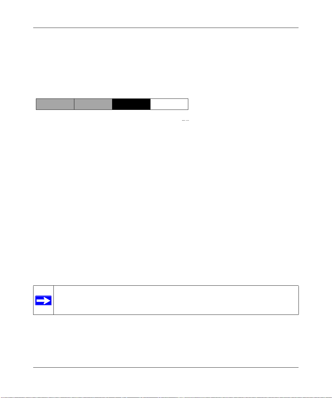
Reference Manual for the 54 Mbps Wireless Router WGR614 v6
C
Subnet addressing allows us to split one IP network address into smaller multiple physical
networks known as subnetworks. Some of the node numbers are used as a subnet number instead.
A Class B address gives us 16 bits of node numbers translating to 64,000 nodes. Most
organizations do not use 64,000 nodes, so there are free bits that can be reassigned. Subnet
addressing makes use of those bits that are free, as shown below.
lass B
Network Subnet Node
Figure B-2: Example of Subnetting a Class B Address
A Class B address can be effectively translated into multiple Class C addresses. For example, the
IP address of 172.16.0.0 is assigned, but node addresses are limited to 255 maximum, allowing
eight extra bits to use as a subnet address. The IP address of 172.16.97.235 would be interpreted as
IP network address 172.16, subnet number 97, and node number 235. In addition to extending
the number of addresses available, subnet addressing provides other benefits. Subnet addressing
allows a network manager to construct an address scheme for the network by using different
subnets for other geographical locations in the network or for other departments in the
organization.
Although the preceding example uses the entire third octet for a subnet address, note that you are
not restricted to octet boundaries in subnetting. To create more network numbers, you need only
shift some bits from the host address to the network address. For instance, to partition a Class C
network number (192.68.135.0) into two, you shift one bit from the host address to the network
address. The new netmask (or subnet mask) is 255.255.255.128. The first subnet has network
number 192.68.135.0 with hosts 192.68.135.1 to 129.68.135.126, and the second subnet has
network number 192.68.135.128 with hosts 192.68.135.129 to 192.68.135.254.
Note: The number 192.68.135.127 is not assigned because it is the broadcast address
of the first subnet. The number 192.68.135.128 is not assigned because it is the network
address of the second subnet.
Network, Routing, Firewall, and Basics B-5
202-10099-01, April 2005
Page 88

Reference Manual for the 54 Mbps Wireless Router WGR6 14 v6
The following table lists the additional subnet mask bits in dotted-decimal notation. To use the
table, write down the original class netmask and replace the 0 value octets with the dotted-decimal
value of the additional subnet bits. For example, to partition your Class C network with subnet
mask 255.255.255.0 into 16 subnets (4 bits), the new subnet mask becomes 255.255.255.240.
Table 7-1. Netmask Notation Translation Tab le for One Octet
Number of Bits Dotted-Decimal Value
1 128
2 192
3 224
4 240
5 248
6 252
7 254
8 255
The following table displays several common netmask values in both the dotted-decimal and the
masklength formats.
Table 7-2. Netmask Formats
Dotted-Decimal Masklength
255.0.0.0 /8
255.255.0.0 /16
255.255.255.0 /24
255.255.255.128 /25
255.255.255.192 /26
255.255.255.224 /27
255.255.255.240 /28
255.255.255.248 /29
255.255.255.252 /30
255.255.255.254 /31
255.255.255.255 /32
Configure all hosts on a LAN segment to use the same netmask for the following reasons:
B-6 Network, Routing, Firewall, and Basics
202-10099-01, April 2005
Page 89

Reference Manual for the 54 Mbps Wireless Router WGR614 v6
• So that hosts recognize local IP broadcast packets
When a device broadcasts to its segment neighbors, it uses a destination address of the local
network address with all ones for the host address. In order for this scheme to work, all devices
on the segment must agree on which bits comprise the host address.
• So that a local router or bridge recognizes which addresses are local and which are remote
Private IP Addresses
If your local network is isolated from the Internet (for example, when using NAT), you can assign
any IP addresses to the hosts without problems. However, the IANA has reserved the following
three blocks of IP addresses specifically for private networks:
10.0.0.0 - 10.255.255.255
172.16.0.0 - 172.31.255.255
192.168.0.0 - 192.168.255.255
Choose your private network number from this range. The DHCP server of the WGR614 v6 router
is preconfigured to automatically assign private addresses.
Regardless of your particular situation, do not create an arbitrary IP address; always follow the
guidelines explained here. For more information about address assignment, refer to RFC 1597,
Address Allocation for Private Internets, and RFC 1466, Guidelines for Management of IP
Address Space. The Internet Engineering Task Force (IETF) publishes RFCs on its Web site at
www.ietf.org.
Single IP Address Operation Using NAT
In the past, if multiple computers on a LAN needed to access the Internet simultaneously , you had
to obtain a range of IP addresses from the ISP. This type of Internet account is more costly than a
single-address account typically used by a single user with a modem, rather than a router. The
WGR614 v6 router employs an address-sharing method called Network Address Translation
(NAT). This method allows several networked computers to share an Internet account using only a
single IP address, which may be statically or dynamically assigned by your ISP.
The router accomplishes this address sharing by translating the internal LAN IP addresses to a
single address that is globally unique on the Internet. The internal LAN IP addresses can be either
private addresses or registered addresses. For more information about IP address translation, refer
to RFC 1631, The IP Network Address Translator (NAT).
Network, Routing, Firewall, and Basics B-7
202-10099-01, April 2005
Page 90
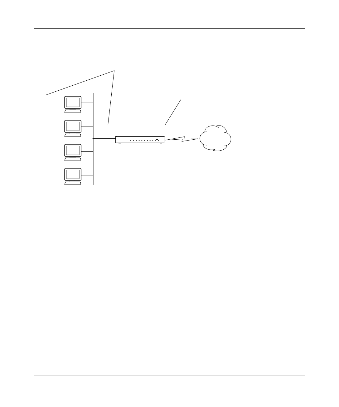
Reference Manual for the 54 Mbps Wireless Router WGR6 14 v6
1
1
1
1
The following figure illustrates a single IP address operation.
Private IP addresses
assigned by user
IP addresses
92.168.0.2
assigned by ISP
92.168.0.3
92.168.0.4
92.168.0.5
192.168.0.1 172.21.15.105
Internet
Figure B-3: Single IP Address Operation Using NAT
This scheme offers the additional benefit of firewall-like protection because the internal LAN
addresses are not available to the Internet through the translated connection. All incoming
inquiries are filtered out by the router. This filtering can prevent intruders from probing your
system. However, using port forwarding, you can allow one computer (for example, a Web server)
on your local network to be accessible to outside users.
MAC Addresses and Address Resolution Protocol
An IP address alone cannot be used to deliver data from one LAN device to another. To send data
between LAN devices, you must convert the IP address of the destination device to its media
access control (MAC) address. Each device on an Ethernet network has a unique MAC address,
which is a 48-bit number assigned to each device by the manufacturer. The technique that
associates the IP address with a MAC address is known as address resolution. Internet Protocol
uses the Address Resolution Protocol (ARP) to resolve MAC addresses.
B-8 Network, Routing, Firewall, and Basics
202-10099-01, April 2005
Page 91

Reference Manual for the 54 Mbps Wireless Router WGR614 v6
If a device sends data to another station on the network and the destination MAC address is not yet
recorded, ARP is used. An ARP request is broadcast onto the network. All stations on the network
receive and read the request. The destination IP address for the chosen station is included as part of
the message so that only the station with this IP address responds to the ARP request. All other
stations discard the request.
Related Documents
The station with the correct IP address responds with its own MAC address directly to the sending
device. The receiving station provides the transmitting station with the required destination MAC
address. The IP address data and MAC address data for each station are held in an ARP table. The
next time data is sent, the address can be obtained from the address information in the table.
For more information about address assignment, refer to the IETF documents RFC 1597, Address
Allocation for Private Internets, and RFC 1466, Guidelines for Management of IP Address Space.
For more information about IP address translation, refer to RFC 1631, The IP Network Address
Translator (NAT).
Domain Name Server
Many of the resources on the Internet can be addressed by simple descriptive names such as
www.NETGEAR.com. This addressing is very helpful at the application level, but the descriptive
name must be translated to an IP address in order for a user to actually contact the resource. Just as
a telephone directory maps names to phone numbers, or as an ARP table maps IP addresses to
MAC addresses, a domain name system (DNS) server maps descriptive names of network
resources to IP addresses.
When a computer accesses a resource by its descriptive name, it first contacts a DNS server to
obtain the IP address of the resource. The computer sends the desired message using the IP
address. Many large organizations, such as ISPs, maintain their own DNS servers and allow their
customers to use the servers to look up addresses.
Network, Routing, Firewall, and Basics B-9
202-10099-01, April 2005
Page 92

Reference Manual for the 54 Mbps Wireless Router WGR6 14 v6
IP Configuration by DHCP
When an IP-based local area network is installed, each computer must be configured with an
IP address. If the computers need to access the Internet, they should also be configured with a
gateway address and one or more DNS server addresses. As an alternative to manual
configuration, there is a method by which each computer on the network can automatically obtain
this configuration information. A device on the network may act as a Dynamic Host Configuration
Protocol (DHCP) server. The DHCP server stores a list or pool of IP addresses, along with other
information (such as gateway and DNS addresses) that it may assign to the other devices on the
network. The WGR614 v6 router has the capacity to act as a DHCP server.
The WGR614 v6 router also functions as a DHCP client when connecting to the ISP. The firewall
can automatically obtain an IP address, subnet mask, DNS server addresses, and a gateway address
if the ISP provides this information by DHCP.
Internet Security and Firewalls
When your LAN connects to the Internet through a router, an opportunity is created for outsiders
to access or disrupt your network. A NAT router provides some protection because by the very
nature of the process, the network behind the router is shielded from access by outsiders on the
Internet. However, there are methods by which a determined hacker can possibly obtain
information about your network or at the least can disrupt your Internet access. A greater degree of
protection is provided by a firewall router.
What is a Firewall?
A firewall is a device that protects one network from another, while allowing communication
between the two. A firewall incorporates the functions of the NAT router, while adding features for
dealing with a hacker intrusion or attack. Several known types of intrusion or attack can be
recognized when they occur. When an incident is detected, the firewall can log details of the
attempt, and can optionally send E-mail to an administrator notifying them of the incident. Using
information from the log, the administrator can take action with the ISP of the hacker. In some
types of intrusions, the firewall can fend off the hacker by discarding all further packets from the
hacker’s IP address for a period of time.
B-10 Network, Routing, Firewall, and Basics
202-10099-01, April 2005
Page 93

Reference Manual for the 54 Mbps Wireless Router WGR614 v6
Stateful Packet Inspection
Unlike simple Internet sharing routers, a firewall uses a process called stateful packet inspection to
ensure secure firewall filtering to protect your network from attacks and intrusions. Since
user-level applications such as FTP and Web browsers can create complex patterns of network
traffic, it is necessary for the firewall to analyze groups of network connection states. Using
Stateful Packet Inspection, an incoming packet is intercepted at the network layer and then
analyzed for state-related information associated with all network connections. A central cache
within the firewall keeps track of the state information associated with all network connections.
All traffic passing through the firewall is analyzed against the state of these connections in order to
determine whether or not it will be allowed to pass through or rejected.
Denial of Service Attack
A hacker may be able to prevent your network from operating or communicating by launching a
Denial of Service (DoS) attack. The method used for such an attack can be as simple as merely
flooding your site with more requests than it can handle. A more sophisticated attack may attempt
to exploit some weakness in the operating system used by your router or gateway. Some operating
systems can be disrupted by simply sending a packet with incorrect length information.
Ethernet Cabling
Although Ethernet networks originally used thick or thin coaxial cable, most installations currently
use unshielded twisted pair (UTP) cabling. The UTP cable contains eight conductors, arranged in
four twisted pairs, and terminated with an RJ45 type connector. A normal straight-through UTP
Ethernet cable follows the EIA568B standard wiring as described below in Table B-1.
Table B-1. UTP Ethernet cable wiring, straight-through
Pin Wire color Signal
1 Orange/White Transmit (Tx) +
2 Orange Transmit (Tx) 3 Green/White Receive (Rx) +
4Blue
5 Blue/White
6 Green Receive (Rx) -
Network, Routing, Firewall, and Basics B-11
202-10099-01, April 2005
Page 94

Reference Manual for the 54 Mbps Wireless Router WGR6 14 v6
Table B-1. UTP Ethernet cable wiring, straight-through (continued)
Pin Wire color Signal
7 Brown/White
8Brown
Category 5 Cable Quality
Category 5 distributed cable that meets ANSI/EIA/TIA-568-A building wiring standards can be a
maximum of 328 feet (ft.) or 100 meters (m) in length, divided as follows:
20 ft. (6 m) between the hub and the patch panel (if used)
295 ft. (90 m) from the wiring closet to the wall outlet
10 ft. (3 m) from the wall outlet to the desktop device
The patch panel and other connecting hardware must meet the requirements for 100 Mbps
operation (Category 5). Only 0.5 inch (1.5 cm) of untwist in the wire pair is allowed at any
termination point.
A twisted pair Ethernet network operating at 10 Mbits/second (10BASE-T) will often tolerate low
quality cables, but at 100 Mbits/second (10BASE-Tx) the cable must be rated as Category 5, or
Cat 5, by the Electronic Industry Association (EIA). This rating will be printed on the cable jacket.
A Category 5 cable will meet specified requirements regarding loss and crosstalk. In addition,
there are restrictions on maximum cable length for both 10 and 100 Mbits/second networks.
Inside Twisted Pair Cables
For two devices to communicate, the transmitter of each device must be connected to the receiver
of the other device. The crossover function is usually implemented internally as part of the
circuitry in the device. Computers and workstation adapter cards are usually media-dependent
interface ports, called MDI or uplink ports. Most repeaters and switch ports are configured as
media-dependent interfaces with built-in crossover ports, called MDI-X or normal ports. Auto
Uplink technology automatically senses which connection, MDI or MDI-X, is needed and makes
the right connection.
Figure B-4 illustrates straight-through twisted pair cable.
B-12 Network, Routing, Firewall, and Basics
202-10099-01, April 2005
Page 95
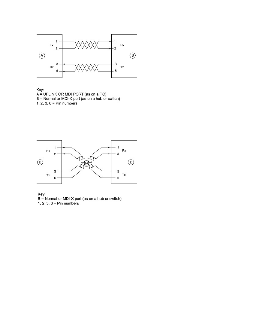
Reference Manual for the 54 Mbps Wireless Router WGR614 v6
Figure B-4: Straight-Through Twisted-Pair Cable
Figure B-5 illustrates crossover twisted pair cable.
Figure B-5: Crossover Twisted-Pair Cable
Network, Routing, Firewall, and Basics B-13
202-10099-01, April 2005
Page 96

Reference Manual for the 54 Mbps Wireless Router WGR6 14 v6
Figure B-6: Category 5 UTP Cable with Male RJ-45 Plug at Each End
Note: Flat “silver satin” telephone cable may have the same RJ-45 plug. However, using telephone
cable results in excessive collisions, causing the attached port to be partitioned or disconnected
from the network.
Uplink Switches, Crossover Cables, and MDI/MDIX Switching
In the wiring table above, the concept of transmit and receive are from the perspective of the
computer, which is wired as Media Dependant Interface (MDI). In this wiring, the computer
transmits on pins 1 and 2. At the hub, the perspective is reversed, and the hub receives on pins 1
and 2. This wiring is referred to as Media Dependant Interface - Crossover (MDI-X).
When connecting a computer to a computer, or a hub port to another hub port, the transmit pair
must be exchanged with the receive pair. This exchange is done by one of two mechanisms. Most
hubs provide an Uplink switch which will exchange the pairs on one port, allowing that port to be
connected to another hub using a normal Ethernet cable. The second method is to use a crossover
cable, which is a special cable in which the transmit and receive pairs are exchanged at one of the
two cable connectors. Crossover cables are often unmarked as such, and must be identified by
comparing the two connectors. Since the cable connectors are clear plastic, it is easy to place them
side by side and view the order of the wire colors on each. On a straight-through cable, the color
order will be the same on both connectors. On a crossover cable, the orange and green pairs will be
exchanged from one connector to the other.
B-14 Network, Routing, Firewall, and Basics
202-10099-01, April 2005
Page 97

Reference Manual for the 54 Mbps Wireless Router WGR614 v6
The WGR614 v6 router incorporates Auto UplinkTM technology (also called MDI/MDIX). Each
LOCAL Ethernet port will automatically sense whether the Ethernet cable plugged into the port
should have a normal connection (e.g. connecting to a computer) or an uplink connection (e.g.
connecting to a router, switch, or hub). That port will then configure itself to the correct
configuration. This feature also eliminates the need to worry about crossover cables, as Auto
Uplink
TM
will accommodate either type of cable to make the right connection.
Network, Routing, Firewall, and Basics B-15
202-10099-01, April 2005
Page 98

Reference Manual for the 54 Mbps Wireless Router WGR6 14 v6
B-16 Network, Routing, Firewall, and Basics
202-10099-01, April 2005
Page 99

Appendix C
Preparing Your Network
This appendix describes how to prepare your network to connect to the Internet through the 54
Mbps Wireless Router WGR614 v6 and how to verify the readiness of broadband Internet service
from an Internet service provider (ISP).
Note: If an ISP technician configured your computer during the installation of a
broadband modem, or if you configured it using instructions provided by your ISP, you
may need to copy the current configuration information for use in the configuration of
your router. Write down this information before reconfiguring your computers. Refer to
“Obtaining ISP Configuration Information for Windows Computers” on page C-21 or
“Obtaining ISP Configuration Information for Macintosh Computers” on page C-22 for
further information.
What You Need To Use a Router with a Broadband Modem
You need to prepare these three things before you begin:
Cabling and Computer Hardware
To use the WGR614 v6 router on your network, each computer must have an 802.11g or 802.11b
wireless adapter or an installed Ethernet Network Interface Card (NIC) and an Ethernet cable. If
the computer will connect to your network using an Ethernet NIC at 100 Mbps, you must use a
Category 5 (Cat 5) cable such as the one provided with your router. For an explanation of Ethernet
cabling, see “Ethernet Cabling“ on page B-11. The cable or DSL broadb and modem mu st provide
a standard 10 Mbps (10BASE-T) or 100 Mbps (100BASE-Tx) Ethernet interface.
Computer Network Configuration Requirements
The WGR614 v6 includes a built-in Web Configuration Manager. To access the configuration
menus on the WGR614 v6, your must use a Java-enabled Web browser program which supports
HTTP uploads such as Microsoft Internet Explorer or Netscape Navigator. Use Internet Explorer
5.0 and above and Netscape Navigator 4.7 and above.
Preparing Your Network C-1
202-10099-01, April 2005
Page 100

Reference Manual for the 54 Mbps Wireless Router WGR6 14 v6
For the initial setup of your router, you will need to connect a computer to the router. This
computer has to be set to automatically get its TCP/IP configuration from the router via DHCP.
Note: For help with DHCP configuration, please use the Windows TCP/IP Configuration
Tutorials on the NETGEAR 54 Mbps Wireless Router WGR614 v6 Resource CD (230-10091-02),
or in this appendix.
Internet Configuration Requirements
Depending on how your Internet service set up your account, you may need one or more of these
configuration parameters to connect your router to the Internet:
• Host and Domain Names
• ISP Login Name and Password
• ISP Domain Name Server (DNS) Addresses
• Fixed IP Address which is also known as Static IP Address
Where Do I Get the Internet Configuration Parameters?
There are several ways you can gather the required Internet connection information.
• Your Internet service provides all the information needed to connect to the Internet. If you
cannot locate this information, you can ask your Internet service to provide it or you can try
one of the options below.
• If you have a computer already connected using the Internet, you can gather the configuration
information from that computer.
— For Windows 95/98/ME, open the Network control panel, select the TCP/IP entry for the
Ethernet adapter, and click Properties. Record all the settings for each tab page.
— For Windows 2000/XP, open the Local Area Network Connection, select the TCP/IP entry
for the Ethernet adapter, and click Properties. Record all the settings for each tab page.
— For Macintosh computers, record the settings in the TCP/IP or Network control panel.
• You may also refer to the NETGEAR 54 Mbps Wireless Router WGR614 v6 Resource CD
(230-10091-02) for the NETGEAR Router ISP Guide which provides Internet connection
information for many ISPs.
Once you locate your Internet configuration parameters, you may want to record them on the page
below.
C-2 Preparing Your Network
202-10099-01, April 2005
 Loading...