

Page 1
ProSecure Web/Email
Security Threat
Management Appliance
STM150/300/600
Reference Manual
NETGEAR, Inc.
350 East Plumeria Drive
San Jose, CA 95134
202-10519-01
1.0
September 2009
Page 2

© 2009 by NETGEAR, Inc. All rights reserved.
Trademarks
NETGEAR and the NETGEAR logo are registered trademarks and ProSecure is a trademark of NETGEAR, Inc.
Microsoft, Windows, and Windows NT ar e registered trademarks of Microsoft Corporation. Other brand and product
names are registered trademarks or trademarks of their respective holders.
Statement of Conditions
In the interest of improving internal design, operational function, and/or reliability, NETGEAR reserves the right to
make changes to the products described in this document without notice.
NETGEAR does not assume any liability that may occur due to the use or application of the product(s) or circuit
layout(s) described herein.
Federal Communications Commission (FCC) Compliance Notice: Radio Frequency
Notice
This equipment has been tested and found to comply with the limits for a Class A digital device, pursuant to Part 15 of
the FCC Rules. These limits are designed to provide reasonable protection against harmful interference when the
equipment is operated in a commercial environment. This equipment generates, uses, and can radiate radio frequency
energy and, if not installed and used in accordance with the instruction manual, may cause harmful inte rferenc e to radio
communications. Operation of this equipment in a residential area is likely to cause harmful interfere nc e in which case
the user will be required to correct the interference at his own expense.
Changes or modifications not expressly approved by NETGEAR could void the user’s authority to operate the
equipment.
EU Regulatory Compliance Statement
The ProSecure Web/Email Security Threat Management Appliance STM150, STM300, or STM600 is compliant with
the following EU Council Directives: EMC Directive 2004/108/EC and Low Voltage Directive 2006/95/EC.
Compliance is verified by testing to the following standards: EN55022, EN55024, and EN60950-1.
For the EU Declaration of Conformity please visit:
http://kb.netgear.com/app/answers/detail/a_id/11621/sno/0.
Bestätigung des Herstellers/Importeurs
Es wird hiermit bestätigt, daß das ProSecure Web/Email Security Threat Management Appliance STM150, STM300, or
STM600 gemäß der im BMPT-AmtsblVfg 243/1991 und Vfg 46/1992 aufgeführten Bestimmungen entstört ist. Das
vorschriftsmäßige Betreiben einiger Geräte (z.B. Testsender) kann jedoch gewissen Beschränkungen unterliegen. Lesen
Sie dazu bitte die Anmerkungen in der Betriebsanleitung.
Das Bundesamt für Zulassungen in der Telekommunikation wurde davon unterrichtet, daß dieses Gerät auf den Markt
gebracht wurde und es ist berechtigt, die Serie auf die Erfüllung der Vorschriften hin zu überprüfen.
Certificate of the Manufacturer/Importer
It is hereby certified that the ProSecure Web/Email Security Threat Management Appliance STM150, STM300, or
STM600 has been suppressed in accordance with the conditions set out in the BMPT-AmtsblVfg 243/1991 and Vfg 46/
1992. The operation of some equipment (for example, test transmitters) in accordance with the regulations may,
however, be subject to certain restrictions. Please refer to the notes in the operating instructions.
ii
v1.0, September 2009
Page 3

Federal Office for Telecommunications Approvals has been notified of the placing of this equipment on the market
and has been granted the right to test the series for compliance with the regulations.
Voluntary Control Council for Interference (VCCI) Statement
This equipment is in the second category (information equipment to be used in a residential area or an adjacent area
thereto) and conforms to the standards set by the Voluntary Control Council for Interference by Data Processing
Equipment and Electronic Office Machines aimed at preventing radio interference in such residential areas.
When used near a radio or TV receiver , it may become the cause of radio interference.
Read instructions for correct handling.
Additional Copyrights
AES Copyright (c) 2001, Dr. Brian Gladman, brg@gladman.uk.net, Worcester, UK.
All rights reserved.
TERMS
Redistribution and use in source and binary forms, with or without modification, are permitted
subject to the following conditions:
1. Redistributions of source code must retain the above copyright notice, this list of
conditions, and the following disclaimer.
2. Redistributions in binary form must reproduce the above copyright notice, this list of
conditions, and the following disclaimer in the documentation and/or other materials
provided with the distribution.
3. The copyright holder’s name must not be used to endorse or promote any products
derived from this software without his specific prior written permission.
This software is provided “as is” with no express or implied warranties of correctness or fitness
for purpose.
v1.0, September 2009
iii
Page 4

Open SSL Copyright (c) 1998–2000 The OpenSSL Project. All rights reserved.
Redistribution and use in source and binary forms, with or without modification, are permitted
provided that the following conditions are met:
1. Redistributions of source code must retain the above copyright notice, this list of
conditions, and the following disclaimer.
2. Redistributions in binary form must reproduce the above copyright notice, this list of
conditions, and the following disclaimer in the documentation and/or other materials
provided with the distribution.
3. All advertising materials mentioning features or use of this software must display the
following acknowledgment: “This product includes software developed by the OpenSSL
Project for use in the OpenSSL Toolkit (
4. The names “OpenSSL Toolkit” and “OpenSSL Project” must not be used to endorse or
promote products derived from this software without prior written permission. For written
permission, contact openssl-core@openssl.org.
5. Products derived from this software may not be called “OpenSSL” nor may “OpenSSL”
appear in their names without prior written permission of the OpenSSL Project.
6. Redistributions of any form whatsoever must retain the following acknowledgment: “This
product includes software developed by the OpenSSL Project for use in the OpenSSL
Toolkit (
THIS SOFTWARE IS PROVIDED BY THE OpenSSL PROJECT “AS IS,” AND ANY
EXPRESSED OR IMPLIED WARRANTIES, INCLUDING, BUT NOT LIMITED TO, THE
IMPLIED WARRANTIES OF MERCHANTABILITY AND FITNESS FOR A PARTICULAR
PURPOSE ARE DISCLAIMED. IN NO EVENT SHALL THE OpenSSL PROJECT OR ITS
CONTRIBUTORS BE LIABLE FOR ANY DIRECT, INDIRECT, INCI DENTAL, SPECIAL,
EXEMPLARY, OR CONSEQUENTIAL DAMAGES (INCLUDING, BUT NOT LIMITED TO,
PROCUREMENT OF SUBSTITUTE GOODS OR SERVICES; LOSS OF USE, DATA, OR
PROFITS; OR BUSINESS INTERRUPTION) HOWEVER CAUSED AND ON ANY THEORY
OF LIABILITY, WHETHER IN CONTRACT, STRICT LIABILITY, OR TORT (INCLUDING
NEGLIGENCE OR OTHERWISE) ARISING IN ANY WAY OUT OF THE USE OF THIS
SOFTWARE, EVEN IF ADVISED OF THE POSSIBILITY OF SUCH DAMAGE.
This product includes cryptographic software written by Eric Young (eay@cryptsoft.com). This
product includes software written by Tim Hudson (tjh@cryptsoft.com).
MD5 Copyright (C) 1990, RSA Data Security, Inc. All rights reserved.
License to copy and use this software is granted provided that it is identified as the “RSA Data
Security, Inc. MD5 Message-Digest Algorithm” in all material mentioning or referencing this
software or this function. License is also granted to make and use derivative works provided
that such works are identified as “derived from the RSA Data Security, Inc. MD5 MessageDigest Algorithm” in all material mentioning or referencing the derived work.
RSA Data Security, Inc. makes no representations concerning ei ther the merchantability of
this software or the suitability of this software for any particular purpose. It is provided “as is”
without express or implied warranty of any kind.
These notices must be retained in any copies of any part of this documentation and/or
software.
http://www.openssl.org/).”
http://www.openssl.org/).”
iv
v1.0, September 2009
Page 5

PPP Copyright (c) 1989 Carnegie Mellon University. All rights reserved.
Redistribution and use in source and binary forms are permitted provided that the above
copyright notice and this paragraph are duplicated in all such forms and that any
documentation, advertising materials, and other materials related to such distribution and use
acknowledge that the software was developed by Carnegie Mellon University. The name of
the University may not be used to endor se or promote products derived from this software
without specific prior written permission.
THIS SOFTWARE IS PROVIDED “AS IS” AND WITHOUT ANY EXPRESS OR IMPLIED
WARRANTIES, INCLUDING, WITHOUT LIMITATION, THE IMPLIED WARRANTIES OF
MERCHANTIBILITY AND FITNESS FOR A PARTICULAR PURPOSE.
Zlib zlib.h. Interface of the zlib general purpose compression library version 1.1.4, March 11th,
2002. Copyright (C) 1995–2002 Jean-loup Gailly and Mark Adler.
This software is provided “as is,” without any express or implied warranty. In no event will the
authors be held liable for any damages arising from the use of this software. Permission is
granted to anyone to use this software for any purpose, including commercial applications,
and to alter it and redistribute it freely, subject to the following restrictions:
1. The origin of this software must not be misrepresented; you must not claim that you wrote
the original software. If you use this software in a product, an acknowledgment in the
product documentation would be appreciated but is not required.
2. Altered source versions must be plainly marked as such, and must not be misrepresented
as being the original software.
3. This notice may not be removed or altered from any source distribution.
Jean-loup Gailly: jloup@gzip.org; Mark Adler: madler@alu mni.caltech.edu.
The data format used by the zlib library is described by RFCs (Request for Comments) 1950
to 1952 in the files
format), and rfc1952.txt (gzip format).
ftp://ds.internic.net/rfc/rfc1950.txt (zlib format), rfc1951.txt (deflate
Product and Publication Details
Model Number: STM
Publication Date: September 2009
Product Family: STM
Product Name: ProSecure Web/Email Security Threat Management Appliance STM150,
STM300, or STM600
Home or Business Product: Business
Language: English
Publication Part Number: 202-10519-01
Publication Version Number 1.0
v1.0, September 2009
v
Page 6

vi
v1.0, September 2009
Page 7

ProSecure Web/Email Security Threat Management (STM) Appliance Refer ence Manual
Contents
About This Manual
Conventions, Formats, and Scope ..................................................................................xiii
How to Print This Manual ................................................................................................xiv
Revision History ..................... ... .......................................... ... ..........................................xiv
Chapter 1
Introduction
What Is the ProSecure Web/Email Security Threat Management Appliance STM150, STM300,
or STM600? ....................................................................................................................1-1
What Can You Do with an STM? ..................................... ............................................... 1-2
Key Features and Capabilities ........................................................................................1-3
Stream Scanning for Content Filtering ............................ .... ... ... ... .... ... ...... ... .... ... ... ..1-4
Autosensing Ethernet Connections with Auto Uplink ...............................................1-4
Easy Installation and Management ..........................................................................1-5
Maintenance and Support ...................... ... ... ... ... .... ... ... ... .... ...... ... .... ... ... ... ... .... ... ... ..1-5
STM Model Comparison ........................... ... .......................................... ... ...............1-5
Service Registration Card with License Keys ............................ ... ... ... .... ... ... ... ... .... ... ... ..1-6
Package Contents ..........................................................................................................1-7
Hardware Features .........................................................................................................1-7
Front Panel Ports and LEDs ....................................................................................1-8
Rear Panel Features ....................................................................................................1-14
Bottom Panel With Product Label ..........................................................................1-15
Choosing a Location for the STM ................................................................................. 1-17
Using the Rack-Mounting Kit ..................................................................................1-18
Chapter 2
Using the Setup Wizard to Provision the STM in Your Network
Choosing a Deployment Scenario ... ... ... ... .... ... ... ... ... .... ... ... ... ....... ... ... .... ... ... ... ... .... ... ... ..2-1
Gateway Deployment ...............................................................................................2-1
Server Group ...................................... .......................................... .... ........................2-2
Segmented LAN Deployment ...................................................................................2-3
v1.0, September 2009
vii
Page 8

ProSecure Web/Email Security Threat Management (STM) Appliance Reference Manual
Understanding the Steps for Initial Connection ..............................................................2-4
Qualified Web Browsers ...........................................................................................2-5
Logging In to the STM ....................................................................................................2-5
Understanding the Web Management Interface Menu Layout ............ ... ... ... ............2-8
Using the Setup Wizard to Perform the Initial Configuration ........................................2-10
Setup Wizard Step 1 of 10: Introduction ................................................................2-10
Setup Wizard Step 2 of 11: Networking Settings ....................... ............. ............. ...2-11
Setup Wizard Step 3 of 11: Time Zone ...................................................................2-12
Setup Wizard Step 4 of 11: Email Security .............................................................2-14
Setup Wizard Step 5 of 11: Web Security ..............................................................2-17
Setup Wizard Step 6 of 11: Email Notification Server Settings ..............................2-19
Setup Wizard Step 7 of 11: Update Settings ....................... ................................... 2-21
Setup Wizard Step 8 of 11: HTTP Proxy Settings ........... ....................................... 2-23
Setup Wizard Step 9 of 11: Web Categories ..........................................................2-24
Setup Wizard Step 10 of 11: Configuration Summary ............................................2-26
Setup Wizard Step 11 of 11: Restarting the System ..............................................2-27
Verifying Proper Installation ..........................................................................................2-27
Testing Connectivity ...............................................................................................2-27
Testing HTTP Scanning .........................................................................................2-27
Registering the STM with NETGEAR ...........................................................................2-28
What to Do Next ...........................................................................................................2-30
Chapter 3
Performing Network and System Management
Configuring Network Settings .........................................................................................3-1
Configuring Session Limits and Timeouts ......................................................................3-5
Configuring the HTTP Proxy Settings .............................................................................3-7
About Users with Administrative and Guest Privileges ...................................................3-9
Changing Administrative Passwords and Timeouts .................................................3-9
Configuring Remote Management Access ...................................................................3-11
Using an SNMP Manager .............................................................................................3-13
Supported MIB Browsers .......................................................................................3-15
Managing the Configuration File ...................................................................................3-16
Backup Settings ................. ... .... ... .......................................... ................................3-16
Restore Settings .....................................................................................................3-17
Reverting to Factory Default Settings ....................................................................3-18
viii
v1.0, September 2009
Page 9

ProSecure Web/Email Security Threat Management (STM) Appliance Refer ence Manual
Updating the Software . ... .... ..........................................................................................3-19
Scheduling Updates ...............................................................................................3-19
Performing a Manual Update .............................................................. ... ................3-21
Critical Updates That Require a Restart ................................................................3-22
Configuring Date and Time Service ..............................................................................3-23
Managing Digital Certificates ........................... ... ... ... .... .......................................... ... ...3-25
Managing the Certificate for HTTPS Scans ................. ... .... ... ... ... .... ... ... ... ... .... ......3-26
Managing Untrusted Certificates .. ...... .... ... ... ... ... .... ... ... ... .... ... ...... .... ... ... ... ... .... ... ...3-29
Managing the Quarantine Settings ...............................................................................3-30
Performance Management .............................. ... ... ... .... ... .......................................... ...3-31
Chapter 4
Content Filtering and Optimizing Scans
About Content Filtering and Scans .................................................................................4-1
Default E-mail and Web Scan Settings ....................................................................4-2
Configuring E-mail Protection .........................................................................................4-4
Customizing E-mail Protocol Scan Settings .............................................................4-4
Customizing E-mail Anti-Virus Settings ....................................................................4-5
E-mail Content Filtering ..........................................................................................4-11
Protecting Against E-mail Spam .............................................................................4-14
Configuring Web and Services Protection ....................................................................4-22
Customizing Web Protocol Scan Settings ..............................................................4-22
Configuring Web Malware Scans ...........................................................................4-24
Configuring Web Content Filtering .........................................................................4-26
Configuring Web URL Filtering ..............................................................................4-32
HTTPS Scan Settings ............................................................................................4-36
Specifying Trusted Hosts ............. .......................................... ................................4-39
Configuring FTP Scans ..........................................................................................4-41
Configuring Application Control ....................................................................................4-44
Setting Scanning Exclusions and Web Access Exceptions ..........................................4-46
Setting Scanning Exclusions . .... ... ... ... .... ... .......................................... ...................4-47
Setting Web Access Exception Rules ....................................................................4-48
Chapter 5
Managing Users, Groups, and Authentication
About Users, Groups, and Domains ...............................................................................5-1
Configuring Groups ........................................................................................................5-2
v1.0, September 2009
ix
Page 10

ProSecure Web/Email Security Threat Management (STM) Appliance Reference Manual
Creating and Deleting Groups by Name ..................................................................5-3
Editing Groups by Name .............. ... ... .... ... ... ... .......................................... ... ............5-4
Creating and Deleting Groups by IP Address and Subnet .. ... ... ...............................5-5
Configuring User Accounts .............................................................................................5-6
Creating and Deleting User Accounts ......................................................................5-6
Editing User Accounts ..............................................................................................5-8
Configuring Authentication .............................................................................................5-9
Understanding Active Directories and LDAP Configurations .................................5-12
Creating and Deleting LDAP and Active Directory Domains ............................... ...5-16
Editing LDAP and Active Directory Domains .................. .... ... ... ... .... ......................5-19
Creating and Deleting RADIUS Domains ...............................................................5-19
Editing RADIUS Domains and Configuring VLANs ................ ................................ 5-22
Global User Settings ................. ... .... ... ... ... .... ... .......................................... ... ................5-24
Viewing and Logging Out Active Users ........................................................................5-25
Chapter 6
Monitoring System Access and Performance
Configuring Logging, Alerts, and Event Notifications .....................................................6-1
Configuring the E-mail Notification Server ...............................................................6-2
Configuring and Activating System, E-mail, and Syslog Logs .................................6-3
Configuring Alerts .....................................................................................................6-8
Monitoring Real-Time Traffic, Security, Statistics, and Web Usage ..............................6-11
Understanding the Information on the Dashboard Screen .....................................6-11
Monitoring Web Usage .............................. .......................................... ... ................6-18
Viewing System Status .................................................................................................6-19
Querying Logs and Generating Reports .......................................................................6-22
Querying the Logs ..................................................................................................6-22
Scheduling and Generating Reports ......................................................................6-28
Viewing and Managing the Quarantine Files ................................................................6-33
Using Diagnostics Utilities ............................................................................................6-40
Using the Network Diagnostic Tools .......................................................................6-41
Using the Realtime Traffic Diagnostics Tool ........................................... ................ 6-42
Gathering Important Log Information and Generating a Network Statistics Report 6-43
Restarting and Shutting Down the STM . ... ... ... ....... ... ... ... .... ... ... ... .... ... ... ... ... .... ... ...6-44
x
v1.0, September 2009
Page 11

ProSecure Web/Email Security Threat Management (STM) Appliance Refer ence Manual
Chapter 7
Troubleshooting and Using Online Support
Basic Functioning ...........................................................................................................7-2
Power LED Not On ...................................................................................................7-2
Test LED or Status LED Never Turns Off .................................................................7-2
LAN or WAN Port LEDs Not On ...............................................................................7-3
Troubleshooting the Web Management Interface ...........................................................7-3
When You Enter a URL or IP Address a Time-out Error Occurs ....................................7-4
Troubleshooting a TCP/IP Network Using a Ping Utility .................................................7-5
Testing the LAN Path to Your STM ..........................................................................7-5
Testing the Path from Your PC to a Remote Device ................................................7-6
Restoring the Default Configuration and Password ............... .... ... ... ... .... ... ... ... ... .... ...... ..7-6
Problems with Date and Time .........................................................................................7-7
Using Online Support .....................................................................................................7-8
Enabling Remote Troubleshooting ...........................................................................7-8
Installing Hot Fixes ...................................................................................................7-9
Sending Suspicious Files to NETGEAR for Analysis .............................................7-10
Accessing the Knowledge Base and Documentation .............................................7-11
Appendix A
Default Settings and Technical Specifications
Appendix B
Related Documents
Index
v1.0, September 2009
xi
Page 12

ProSecure Web/Email Security Threat Management (STM) Appliance Reference Manual
xii
v1.0, September 2009
Page 13
ProSecure Web/Email Security Threat Management (STM) Appliance Refer ence Manual
About This Manual
The NETGEAR® Pr oSecur e™ Web/Email Security Thre at Management Appliance STM Refer ence
Manual describes how to configure and troubleshoot a ProSecure Web/Email Security Threat
Management Appliance STM150, STM300, or STM600. The information in this manual is
intended for readers with intermediate computer and networking skills.
Conventions, Formats, and Scope
The conventions, formats, and scope of this manual are described in the following paragraphs:
• Typographical conventions. This manual uses the following typographical conventions:
Italic Emphasis, books, CDs
Bold User input, IP addresses, GUI screen text
Fixed Command prompt, CLI text, code
italic URL links
• Formats. This manual uses the following formats to highlight special messages:
Note: This format is used to highlight information of importance or special interest.
Tip: This format is used to highlight a procedure that will save time or resources.
Warning: Ignoring this type of note might result in a malfunction or damage to the
equipment.
Danger: This is a safety warning. Failure to take heed of this notice might result in
personal injury or death.
v1.0, September 2009
xiii
Page 14
ProSecure Web/Email Security Threat Management (STM) Appliance Reference Manual
• Scope. This manual is written for the STM according to these specifications:
Product ProSecure Web/Email Security Threat Management Appliance
STM150, STM300, or STM600
Manual Publication Date September 2009
For more information about network, Internet, firewall, and VPN technologies, click the links to
the NETGEAR website in Appendix B, “Related Documents.”
Note: Product updates are available on the NETGEAR website at
http://prosecure.netgear.com or http://kb.netgear.com/app/home.
Note: Go to http://prosecure.netgear.com/community/forum.php for information about
the ProSecure™ forum and to become part of the ProSecure™ community.
How to Print This Manual
T o print this manual, your computer must have the free Adobe Acrobat reader installed in order to
view and print PDF files. The Acrobat reader is available on the Adobe Web site at
http://www.adobe.com.
Tip: If your printer supports printing two pages on a single sheet of paper, you can save
paper and printer ink by selecting this feature.
Revision History
Manual Part
Number
202-10519-01 1.0 September 2009 Initial publication of this reference manual.
xiv
Manual
Ver sion
Number
Publication
Date
Description
v1.0, September 2009
Page 15

ProSecure Web/Email Security Threat Management (STM) Appliance Refer ence Manual
Chapter 1
Introduction
This chapter provides an overview of the features and capabilities of the ProSecure Web/Email
Security Threat Management Appliance STM150, STM300, or STM600. It also identifies the
physical features of the appliances and the contents of the product packages.
This chapter contains the following sections:
• “What Is the ProSecure Web/Email Security Threat Management Appliance STM150,
STM300, or STM600? on this page.
• “What Can You Do with an STM?” on page 1-2.
• “Key Features and Capabilities” on page 1-3.
• “Service Registration Card with License Keys” on page 1-6.
• “Rear Panel Features” on page 1-14.
• “Bottom Panel With Product Label” on page 1-15.
• “Choosing a Location for the STM” on page 1-17.
What Is the ProSecure Web/Email Security Threat Management Appliance STM150, STM300, or STM600?
The ProSecure Web/Email Security Threat Management Appliance STM150, STM300, or
STM600, hereafter referred to as the STM, is an appliance-based, W eb and e-mail security solution
that protects the network perimeter against Web-borne threats from spyware, viruses, e-mail, and
blended threats. Ideally deployed at the gateway, it serves as the network’s first line of defense
against all types of threats, and complements firewalls, Intrusion Detection Systems (IDS)/
Intrusion Prevention Systems (IPS), dedicated Intranet security products, and endpoint anti-virus
and anti-spyware software.
Powered by patent-pending Stream Scanning technology and backed by one of the most
comprehensive malware databases in the industry, the STM can detect and stop all known spyware
and viruses at the gateway, preventing them from reaching your desktops and servers, where
cleanup would be much more difficult.
Introduction 1-1
v1.0, September 2009
Page 16

ProSecure Web/Email Security Threat Management (STM) Appliance Reference Manual
In addition to scanning HTTP, HTTPS, FTP, SMTP, POP3, and IMAP traffic, the STM protects
networks against spam phishing attacks and unwanted Web use. The STM is a plug-and-play
device that can be installed and configured within minutes.
What Can You Do with an STM?
The STM combines robust protection against malware threats with ease of use and advanced
reporting and notification features to help you deploy and manage the device with minimal effort.
Here are some of the things that you can do with the STM:
• Protect the network instantly. The STM is a plug-and-play security solution that can be
instantly added to networks without requiring network reconfiguration.
• Scan network traffic for malware. Using the patent-pending Stream Scanning technology,
you can configure the STM to scan HTTP, HTTPS, FTP, SMTP, POP3, and IMAP protocols.
Unlike traditional batch-based scan engines that need to cache the entire file before they can
scan, this scan engine checks traffic as it enters the network, ensuring unimpeded network
performance.
• Set access policies for individual users or groups. You can configure W eb and e-mail access
access policies for individual users and groups based on the STM’s local database, on group IP
address, on LDAP domain, group, or user, or on RADIUS VLAN.
• Receive real-time alerts and generate comprehensive reports. You can configure the STM
to send alerts when a malware attack or outbreak is detected on the network. Real-time alerts
can be sent by e-mail, allowing you to monitor malware events wherever you are.
By configuring the STM to send malware alerts, you can isolate and clean the infected
computer before the malware incident can develop into a full-blown outbreak. The STM also
provides comprehensive reports that you can use to analyze network and malware trends.
• Manage through SNMP support. You can enable and configure the STM’ s SNMP settings to
receive SNMP traps through a supported MIB browser.
• Allow automated component updates. Downloading components regularly is the key to
ensuring updated protection against new threats. The STM makes this administrative task
easier by supporting automatic malware pattern, program, and engine updates.
1-2 Introduction
v1.0, September 2009
Page 17

ProSecure Web/Email Security Threat Management (STM) Appliance Refer ence Manual
Key Features and Capabilities
The STM provides the following key features and capabilities:
• Up to two pairs of 10/100/1000 Mbps Gigabit Ethernet WAN ports (see “STM Model
Comparison” on page 1-5).
• Scalable support (see “STM Model Comparison” on page 1-5) for:
– up to 600 concurrent users
– up to 6000 concurrently scanned HTTP sessions
– up to 239 MB/s HTTP throughput
– up to 960,000 e-mails per hour SMTP throughput.
• Patent-pending Stream Scanning technology that enables scanning of real-time protocols such
as HTTP.
• Comprehensive Web and e-mail inbound and outbound security, covering six major network
protocols: HTTP, HTTPS, FTP, SMTP, POP3, and IMAP.
• URL content filtering with 64 categories.
• Malware database containing hundreds of thousands of signatures of spyware, viruses, and
other malware threats.
• Very frequently updated malware signatures, hourly if required. The STM can automatically
check for new malware signatures as frequently as every 15 minutes.
• Multiple anti-spam technologies to provide extensive protection against unwanted e-mails.
• Spam and malware quarantine for easy analysis.
• Web application control, including access control for instant messaging, media applications,
peer-to-peer applications, and Web-based tools and to olbars.
• User management with LDAP, Active Directory, and RADIUS integration, allowing access
policy configuration per user and per group.
• Easy, Web-based wizard setup for installation and management.
• SNMP-manageable.
• Dedicated management interface. (This feature is model dependent, see “STM Model
Comparison” on page 1-5).
• Hardware bypass port to prevent network disruption in case failure. (This feature is model
dependent, see “STM Model Comparison” on page 1-5).
• Front panel LEDs for easy monitoring of status and activity.
• Internal universal switching power supply.
Introduction 1-3
v1.0, September 2009
Page 18

ProSecure Web/Email Security Threat Management (STM) Appliance Reference Manual
Stream Scanning for Content Filtering
Stream Scanning is based on the simple observation that network traffic travels in streams. The
STM scan engine starts receiving and analyzing traffic as the stream enters the network. As soon
as a number of bytes are available, scanning starts. The scan engine continues to scan more bytes
as they become available, while at the same time another thread starts to deliver the bytes that have
been scanned.
This multithreaded approach, in which the receiving, scanning, and delivering processes occur
concurrently, ensures tha t network performance remains unimpeded. The result is file scanning is
up to five times faster than with traditional anti-virus solutions—a performance advantage that you
will notice.
Stream Scanning also enables organizations to withstand massive spikes in traffic, as in the event
of a malware outbreak. The scan engine has the following capabilities:
• Real-time protection. The patent-pending Stream Scanning technology enables scanning of
previously undefended real-time protocols, such as HTTP. Network activities susceptible to
latency (for example, Web browsing) are no longer brought to a standstill.
• Comprehensive protection. Provides both Web and e-mail security, covering six major
network protocols: HTTP, HTTPS, FTP, SMTP, POP3, and IMAP. The STM uses enterpriseclass scan engines employing both signature-based and Distributed Spam Analysis to stop
both known and unknown threats. The malware database cont ains hundreds of thousands of
signatures of spyware, viruses, and other malware.
• Objectionable traffic protection. The STM prevents objectionable content from reaching
your computers. You can control access to the Internet content by screening for Web
categories, Web addresses, and Web services. You can log and report attempts to access
objectionable Internet sites.
• Automatic signature updates. Malware signatures are updated as frequently as every hour,
and the STM can check automatically for new signatures as frequently as every 15 minutes.
Autosensing Ethernet Connections with Auto Uplink
With its internal 10/100/1000 ports, the STM can connect to either a 10 Mbps standard Ethernet
network, a 100 Mbps Fast Ethernet network, or a 1000 Mbps Gigabit Ethernet network. The
interfaces are autosensing and capable of full-duplex or half-duplex operation.
TM
The STM incorporates Auto Uplink
whether the Ethernet cable plugged into the port should have a “normal” connection such as to a
PC or an “uplink” connection such as to a switch or hub. That port then configures itself to the
correct configuration. This feature eliminates the need to think about crossover cables, as Auto
Uplink accommodates either type of cable to make the right connection.
1-4 Introduction
technology. Each Ethernet port automatically senses
v1.0, September 2009
Page 19

ProSecure Web/Email Security Threat Management (STM) Appliance Refer ence Manual
Easy Installation and Management
You can install, configure, and operate the STM within minutes after connecting it to the network.
The following features simplify installation and management tasks:
• Browser-based management. Browser-based configuration allows you to easily configure
the STM from almost any type of personal computer, such as Windows, Macintosh, or Linux.
A user-friendly Setup Wizard is provided and online help documentation is built into the
browser-based Web Management Interface.
• SNMP. The STM supports the Simple Network Management Protocol (SNMP) to let you
monitor and manage log resources from an SNMP-compliant system manager. The SNMP
system configuration lets you change the system variables for MIB2.
• Diagnostic functions. The STM incorporates built-in diagnostic functions such as a Ping
utility, Trace-route utility, DNS lookup utility, and remote restart.
• Remote management. The STM allows you to log in to the Web Management Interface from
a remote location on the Internet. For security, you can limit remote management access to a
specified remote IP address or range of addresses.
• Visual monitoring. The STM’s front panel LEDs provide an easy way to monitor its status
and activity.
Maintenance and Support
NETGEAR offers technical support seven days a week, 24 hours a day, according to the terms
identified in the Warranty and Support information card provided with your product.
STM Model Comparison
Table 1-1 compares the three STM models to show the differences:
Table 1-1. Differences Between the STM Models
Feature STM150 STM300 STM600
Performance and Sizing Guidelines
Concurrent Users up to 150 up to 300 up to 600
Web Scan Throughput 43 Mbps 148 Mbps 239 Mbps
Concurrent Scanned HTTP Connections 1500 3000 6000
SMTP Throughput (e-mails per hour) 139,000 420,000 960,000
Introduction 1-5
v1.0, September 2009
Page 20
ProSecure Web/Email Security Threat Management (STM) Appliance Reference Manual
Table 1-1. Differences Between the STM Models (continued)
Feature STM150 STM300 STM600
Hardware
Gigabit RJ-45 Ports Total of 5 ports:
• 1 uplink
• 4 downlink
Gigabit RJ45 Port Pairs with Failure Bypass 0 1 pair of ports 2 pairs of ports
Dedicated Management VLAN RJ45 Ports 0 1 1
a. The STM600 provides two pairs of ports, allowing for support of two separate networks or subnets with strict traffic
separation.
Total of 3 ports:
• 1 pair of ports
(1 uplink and
1 downlink)
• 1 management
Total of 5 ports:
• 2 pairs of ports
(2 uplink and
2 downlink)
• 1 management
Service Registration Card with License Keys
Be sure to store the license key card that came with your STM in a secure location. You do need
these keys to activate your product during the initial setup.
a
Figure 1-1
1-6 Introduction
v1.0, September 2009
Page 21
ProSecure Web/Email Security Threat Management (STM) Appliance Refer ence Manual
Note: When you reset the STM to the original factory default settings after you have
entered the license keys to activate the STM (see “Registering the STM with
NETGEAR” on page 2-28), the license keys are erased. The license keys and the
different types of licenses that are available for the STM are no longer displayed
on the Registration screen. However, after you have reconfigured the STM to
connect to the Internet and to the NETGEAR registration server, the STM
retrieves and restores all registration information based on its MAC address and
hardware serial number. You do not need to re-enter the license keys and
reactivate the STM.
Package Contents
The STM product package contains the following items:
• ProSecure Web/Email Security Threat Management Appliance STM150, STM300, or
STM600
• One AC power cable
• Rubber feet (4) with adhesive backing
• One rack-mount kit
• Straight through Category 5 Ethernet Cable
• ProSecure™ Web/Email Security Threat Management Applliance STM150, STM300, or
STM600 Installation Guide
• Depending on the model purchased, Service Registration Card with License Key(s)
• Warranty and Support Information Card
If any of the parts are incorrect, missing, or damaged, contact your NETGEAR dealer. Keep the
carton, including the original packing materials, in case you need to return the product for repair.
Hardware Features
The front panel ports and LEDs, rear panel ports, and bottom label of the STM models are
described in this section.
Introduction 1-7
v1.0, September 2009
Page 22
ProSecure Web/Email Security Threat Management (STM) Appliance Reference Manual
1) Power LED
2) Test LED
3) USB Port
4) Uplink Port
5) Downlink Ports
4) Uplink LEDs
5) Downlink LEDs
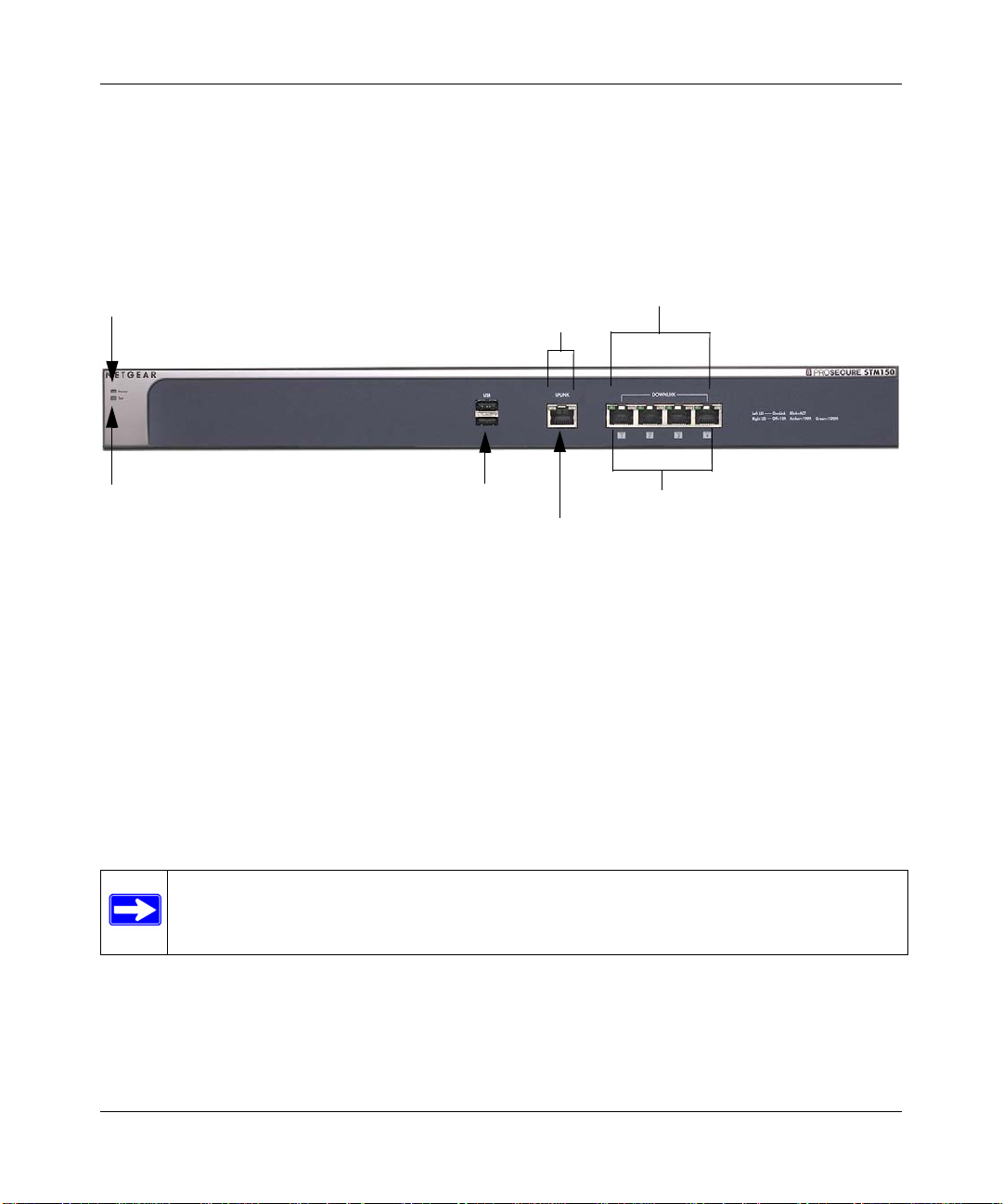
Front Panel Ports and LEDs
The front panels of the three STM models provide different components.
STM150 Front Panel
Figure 1-2 shows the front panel ports and status light-emitting diodes (LEDs) of the STM150.
Figure 1-2
From left to right, the STM150’s front panel shows the following ports and LEDs:
1. Power LED.
2. Test LED.
3. One non-functioning USB port: this port is included for future management enhancements.
4. One uplink (WAN) Gigabit Ethernet port with an RJ-45 connector, left LED, and right LED.
5. Four downlink (LAN) Gigabit Ethernet ports with RJ-45 connectors, left LEDs, and right
1-8 Introduction
The port is currently not operable on any STM model.
LEDs.
Note: All Gigabit Ethernet ports provide switched N-way, automatic speed-negotiating,
auto MDI/MDIX technology.
v1.0, September 2009
Page 23

ProSecure Web/Email Security Threat Management (STM) Appliance Refer ence Manual
The function of each STM150 LED is described in the following table:
Table 1-2. LED Descriptions for the STM150
Object Activity Description
Power On (Green) Power is supplied to the STM.
Off Power is not supplied to the STM.
Test On (Amber) during
startup.
Off The system has completed its initialization successfully. The Test LED
Blinking (Amber) The STM is shutting down.
Uplink (WAN) Port
The STM is initializing. After approximately 2 minutes, when the STM
has completed its initialization, the Test LED turns off. If the Test LED
remains on, the initialization has failed.
should be off during normal operation.
Software is being updated.
A hot fix is being installed.
One of the three licenses has expired. To stop the Test LED from
blinking, renew the license, or click the Stop LED Blinking button on
the System Status screen (see “Viewing System Status” on page 6-19).
Left LED Off The WAN port has no physical link, that is, no Ethernet cable is plugged
into the STM.
On (Green) The WAN port has a valid connection with a device that provides an
Internet connection.
Blink (Green) Data is being transmitted or received by the WAN port.
Right LED Off The WAN port is operating at 10 Mbps.
On (Amber) The WAN port is operating at 100 Mbps.
On (Green) The WAN port is operating at 1000 Mbps.
Downlink (LAN) Ports
Left LED Off The LAN port has no link.
On (Green) The LAN port has detected a link with a connected Ethernet device.
Blink (Green) Data is being transmitted or received by the LAN port.
Right LED Off The LAN port is operating at 10 Mbps.
On (Amber) The LAN port is operating at 100 Mbps.
On (Green) The LAN port is operating at 1000 Mbps.
Introduction 1-9
v1.0, September 2009
Page 24
ProSecure Web/Email Security Threat Management (STM) Appliance Reference Manual
3) Status LED
4) HDD LED
5) USB Port
7) Uplink Port
8) Downlink Port
7) Uplink LEDs
8) Downlink LEDs
2) Power LED
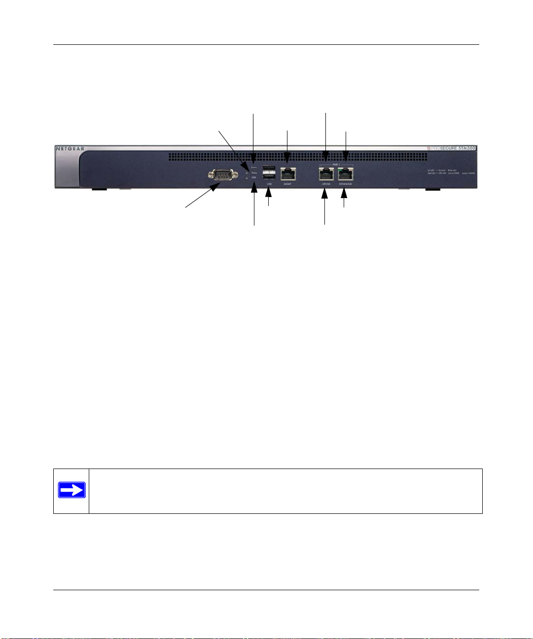
1) Console Port
6) Mgmt Port
Front Panel STM300
Figure 1-3 shows the front panel ports and LEDs of the STM300.
Figure 1-3
From left to right, the STM300’s front panel shows the following ports and LEDs:
1. Console port. Port for connecting to an optional console terminal. The ports has a DB9 male
connector. The default baud rate is 9600 K. The pinouts are: (2) Tx, (3) Rx, (5) and (7) Gnd.
2. Power LED.
3. Status LED.
4. Hard drive (HDD) LED.
5. One non-functioning USB port: this port is included for future management enhancements.
The port is currently not operable on any STM model.
6. Dedicated management (Mgmt) Gigabit Ethernet port with an RJ-45 connector.
7. One uplink (WAN) Gigabit Ethernet port with an RJ-45 connector, left LED, and right LED.
8. One downlink (LAN) Gigabit Ethernet port with RJ-45 connectors, left LEDs, and right LED.
Note: All Gigabit Ethernet ports provide switched N-way, automatic speed-negotiating,
auto MDI/MDIX technology.
1-10 Introduction
v1.0, September 2009
Page 25

ProSecure Web/Email Security Threat Management (STM) Appliance Refer ence Manual
The function of each STM300 LED is described in the following table:
Table 1-3. LED Descriptions for the STM300
Object Activity Description
Power On (Green) Power is supplied to the STM.
Off Power is not supplied to the STM.
Status On (Amber) during
startup.
Off The system has completed its initialization successfully. The Status
Blinking (Amber) The STM is shutting down.
HDD On (Green) Information is being written to the hard drive.
Off No hard drive activity.
The STM is initializing. After approximately 2 minutes, when the STM
has completed its initialization, the Status LED turns off. If the Status
LED remains on, the initialization has failed.
LED should be off during normal operation.
Software is being updated.
A hot fix is being installed.
One of the three licenses has expired. To stop the Status LED from
blinking, renew the license, or click the Stop LED Blinking button on
the System Status screen (see “Viewing System Status” on page 6-19).
Uplink (WAN) Port
Left LED Off The WAN port has no physical link, that is, no Ethernet cable is plugged
into the STM.
On (Green) The WAN port has a valid connection with a device that provides an
Internet connection.
Blink (Green) Data is being transmitted or received by the WAN port.
Right LED Off The WAN port is operating at 10 Mbps.
On (Green) The WAN port is operating at 100 Mbps.
On (Amber) The WAN port is operating at 1000 Mbps.
Downlink (LAN) Ports
Left LED Off The LAN port has no link.
On (Green) The LAN port has detected a link with a connected Ethernet device.
Blink (Green) Data is being transmitted or received by the LAN port.
Right LED Off The LAN port is operating at 10 Mbps.
On (Green) The LAN port is operating at 100 Mbps.
On (Amber) The LAN port is operating at 1000 Mbps.
Introduction 1-11
v1.0, September 2009
Page 26
ProSecure Web/Email Security Threat Management (STM) Appliance Reference Manual
3) Status LED
4) HDD LED
5) USB Port
2) Power LED
1) Console Port
6) Mgmt Port
7) Pair 1 LEDs
8) Pair 2 LEDs
7) Pair 1 Ports
8) Pair 2 Ports
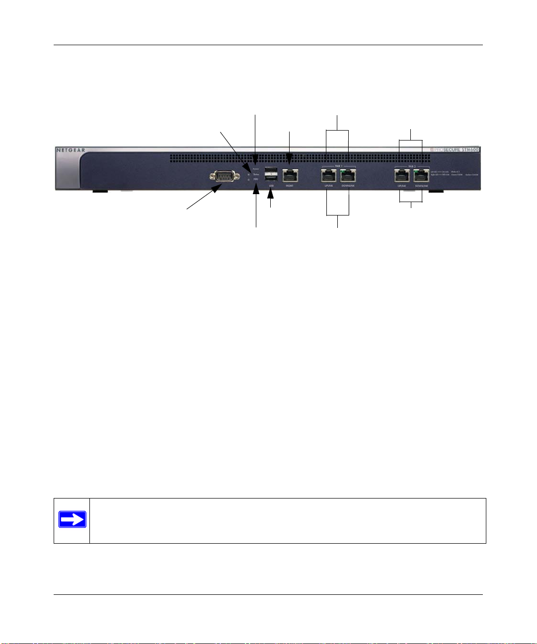
Front Panel STM600
Figure 1-4 shows the front panel ports and LEDs of the STM600.
Figure 1-4
From left to right, the STM600’s front panel shows the following ports and LEDs:
1. Console port. Port for connecting to an optional console terminal. The ports has a DB9 male
connector. The default baud rate is 9600 K. The pinouts are: (2) Tx, (3) Rx, (5) and (7) Gnd.
2. Power LED.
3. Status LED.
4. Hard drive (HDD) LED.
5. One non-functioning USB port: this port is included for future management enhancements.
The port is currently not operable on any STM model.
6. Dedicated management (Mgmt) Gigabit Ethernet port with an RJ-45 connector.
7. Pair 1 uplink (WAN) and downlink (LAN) Gigabit Ethernet ports with RJ-45 connectors, left
LEDs, and right LEDs.
8. Pair 2 uplink (WAN) and downlink (LAN) Gigabit Ethernet ports with RJ-45 connectors, left
LEDs, and right LEDs.
Note: All Gigabit Ethernet ports provide switched N-way, automatic speed-negotiating,
auto MDI/MDIX technology.
1-12 Introduction
v1.0, September 2009
Page 27

ProSecure Web/Email Security Threat Management (STM) Appliance Refer ence Manual
The function of each STM600 LED is described in the following table:
Table 1-4. LED Descriptions for the STM600
Object Activity Description
Power On (Green) Power is supplied to the STM.
Off Power is not supplied to the STM.
Status On (Amber) during
startup.
Off The system has completed its initialization successfully. The Status
Blinking (Amber) The STM is shutting down.
HDD On (Green) Information is being written to the hard drive.
Off No hard drive activity.
The STM is initializing. After approximately 2 minutes, when the STM
has completed its initialization, the Status LED turns off. If the Status
LED remains on, the initialization has failed.
LED should be off during normal operation.
Software is being updated.
A hot fix is being installed.
One of the three licenses has expired. To stop the Status LED from
blinking, renew the license, or click the Stop LED Blinking button on
the System Status screen (see “Viewing System Status” on page 6-19).
Uplink (WAN) Port
Left LED Off The WAN port has no physical link, that is, no Ethernet cable is plugged
into the STM.
On (Green) The WAN port has a valid connection with a device that provides an
Internet connection.
Blink (Green) Data is being transmitted or received by the WAN port.
Right LED Off The WAN port is operating at 10 Mbps.
On (Green) The WAN port is operating at 100 Mbps.
On (Amber) The WAN port is operating at 1000 Mbps.
Downlink (LAN) Ports
Left LED Off The LAN port has no link.
On (Green) The LAN port has detected a link with a connected Ethernet device.
Blink (Green) Data is being transmitted or received by the LAN port.
Right LED Off The LAN port is operating at 10 Mbps.
On (Green) The LAN port is operating at 100 Mbps.
On (Amber) The LAN port is operating at 1000 Mbps.
Introduction 1-13
v1.0, September 2009
Page 28
ProSecure Web/Email Security Threat Management (STM) Appliance Reference Manual
1) Console Port
2) Lock
3) Power Button
4) Reset Button
5) AC Power Socket
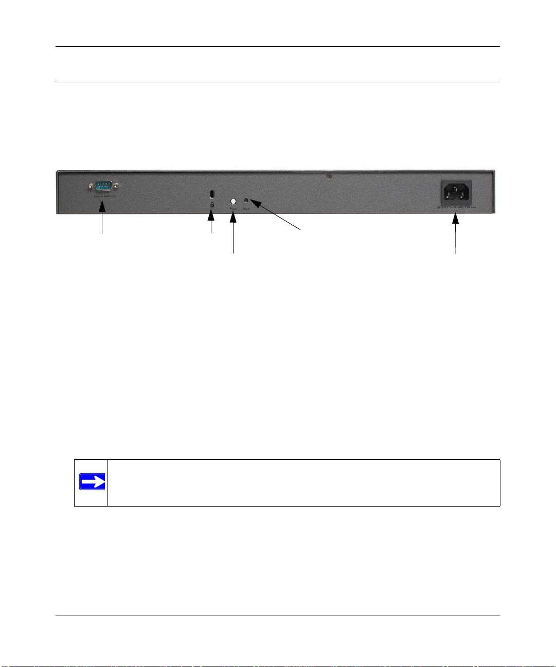
Rear Panel Features
The rear panel of the STM150 differs from the rear panels of the STM300 and STM600.
Rear Panel STM150
Figure 1-5 shows the rear panel components of the STM150.
Figure 1-5
From left to right, the STM150’s rear panel components are:
1. Console port. Port for connecting to an optional console terminal. The ports has a DB9 male
connector. The default baud rate is 9600 K. The pinouts are: (2) Tx, (3) Rx, (5) and (7) Gnd.
2. Kensington lock. Attach an optional Kensington lock to prevent unauthorized removal of the
STM150.
3. Power Button. Press to restart the STM150. Restarting does not reset the STM150 to its
factory defaults.
4. Reset Button. Using a sharp object, press and hold this button for about 10 seconds until the
front panel Test light flashes and the STM150 returns to factory default settings.
5. AC power socket. Attach the power cord to this socket.
1-14 Introduction
Note: If you reset the STM150, all configuration settings are lost and the default
passwords are restored.
v1.0, September 2009
Page 29
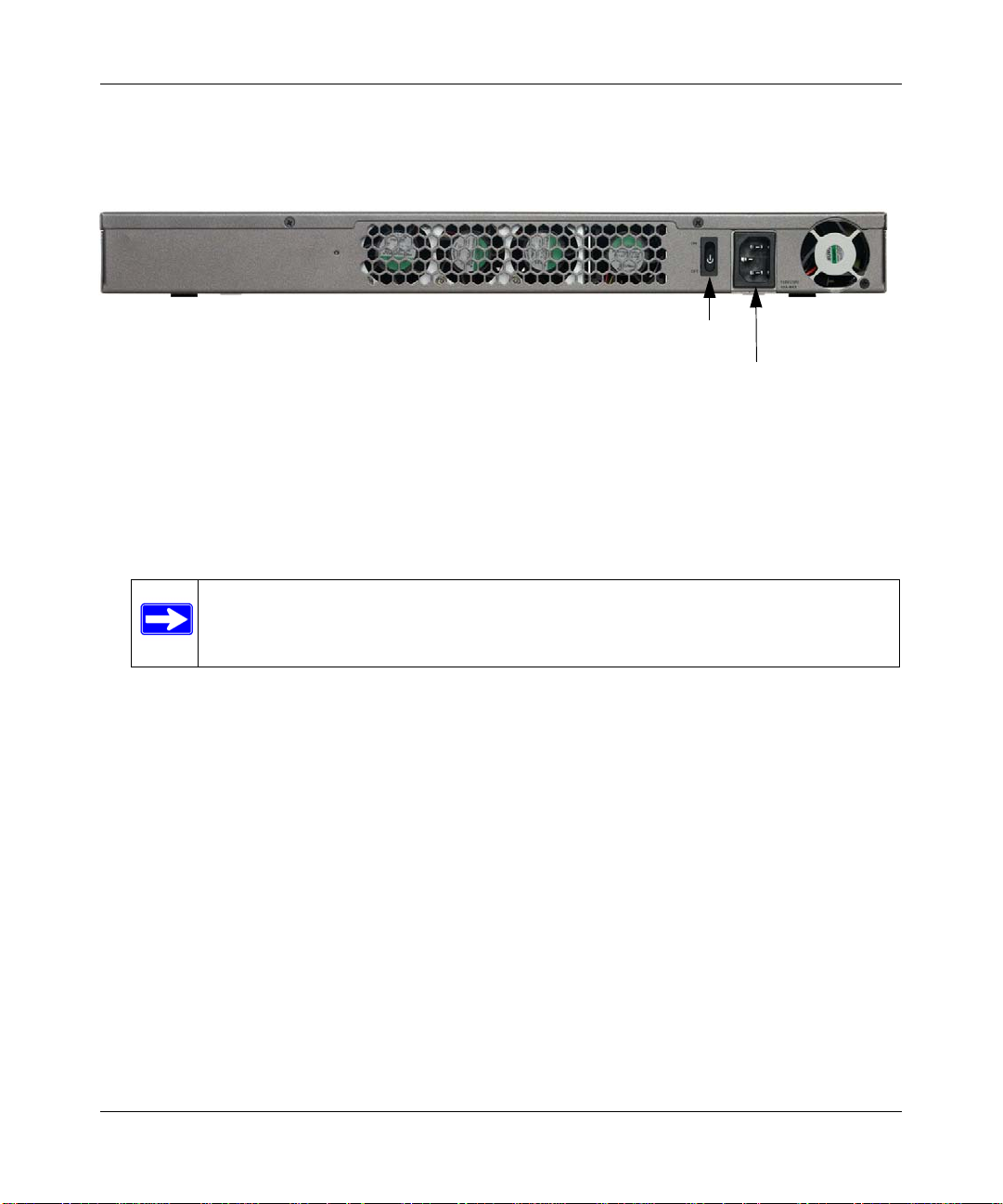
ProSecure Web/Email Security Threat Management (STM) Appliance Refer ence Manual
1) Power Switch
2) AC Power Socket
Rear Panel STM300 and STM600
The rear panels of the STM300 and STM600 are identical.
Figure 1-6 shows the rear panel components of the STM300 and STM600.
Figure 1-6
From left to right, the STM300’s and STM600’s rear panel components (excluding the four fan air
outlets) are:
1. Power switch. Switch to turn the STM300 or STM600 on or off. Restarting does not reset the
STM300 or STM600 to its factory defaults.
Note: The STM300 and STM600 do not provide a Reset button. To reset the
STM300 or STM600 to factory default setting using the Web Management
Interface, see “Reverting to Factory Default Settings” on page 3-18.
2. AC power socket. Attach the power cord to this socket.
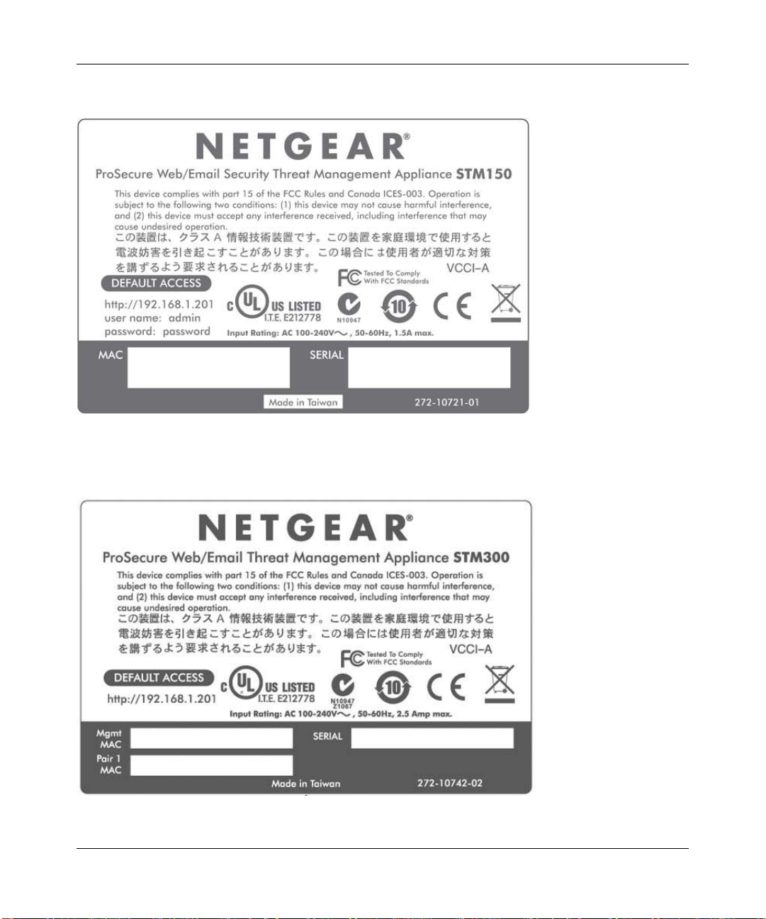
Bottom Panel With Product Label
The product label on the bottom of the STM’s enclosure displays the STM’s default IP address,
default user name, and default password, as well as regulatory compliance, input power, and other
information.
Introduction 1-15
v1.0, September 2009
Page 30
ProSecure Web/Email Security Threat Management (STM) Appliance Reference Manual
STM150 Product Label
Figure 1-7
STM300 Product Label
Figure 1-8
1-16 Introduction
v1.0, September 2009
Page 31

ProSecure Web/Email Security Threat Management (STM) Appliance Refer ence Manual
STM600 Product Label
Figure 1-9
Choosing a Location for the STM
The STM is suitable for use in an office environment where it can be free-standing (on its runner
feet) or mounted into a standard 19-inch equipment rack. Alternatively, you can rack-mount the
STM in a wiring closet or equipment room. A mounting kit, containing two mounting brack ets and
four screws, is provided in the STM package.
Consider the following when deciding where to position the STM:
• The unit is accessible and cables can be connected easily.
• Cabling is away from sources of electrical noise. These include lift shafts, microwave ovens,
and air-conditioning units.
• Water or moisture cannot enter the case of the unit.
• Airflow around the unit and through the vents in the side of the case is not restricted. Provide a
minimum of 25 mm or 1 inch clearance.
• The air is as free of dust as possible.
Introduction 1-17
v1.0, September 2009
Page 32

ProSecure Web/Email Security Threat Management (STM) Appliance Reference Manual
• Temperature operating limits are not like l y to be exceeded. Install the unit in a clean, airconditioned environment. For information abou t the recommen ded operatin g temperatures for
the STM, see Appendix A, “Default Settings and Technical Specifications.”
Using the Rack-Mounting Kit
Use the mounting kit for the STM to install the appliance in a rack. (A mounting kit is provided in
the product package for the STM). The mounting brackets that are supplied with the STM are
usually installed before the unit is shipped out. If the brackets are not yet installed, attach them
using the supplied hardware.
Figure 1-10
Before mounting the STM in a rack, verify that:
• You have the correct screws (supplied with the installation kit).
• The rack onto which you will mount the STM is suitably located.
1-18 Introduction
v1.0, September 2009
Page 33

ProSecure Web/Email Security Threat Management (STM) Appliance Refer ence Manual
Chapter 2
Using the Setup Wizard to Provision the STM in
Your Network
This chapter describes provisioning the STM in your network. This chapter contains the following
sections:
• “Choosing a Deployment Scenario on this page.
• “Understanding the Steps for Initial Connection” on page 2-4.
• “Registering the STM with NETGEAR” on page 2-28.
• “Verifying Proper Installation” on page 2-27.
• “Verifying Proper Installation” on page 2-27.
• “What to Do Next” on page 2-30.
Choosing a Deployment Scenario
The STM is an inline transparent bridge appliance that can easily be deployed to any point on the
network without requiring network reconfiguration or additional hardware.
The following are the most common deployment scenarios for the STM. Depending on your
network environment and the areas that you want to protect, you can choose one or a combination
of the deployment scenarios that are described in the following sections:
• “Gateway Deployment” on page 2-1.
• “Server Group” on page 2-2.
• “Segmented LAN Deployment” on page 2-3.
Gateway Deployment
In a typical gateway deployment scenario, a single STM appliance is installed at the gateway—
between the firewall and the LAN core switch—to protect the network against all malware threats
entering and leaving the gateway . Installing the STM behind the firewall protects it from denial of
service (DoS) attacks. Figure 2-1 on page 2-2 shows a typical gateway deployment scenario.
Using the Setup Wizard to Provision the STM in Your Network 2-1
v1.0, September 2009
Page 34

ProSecure Web/Email Security Threat Management (STM) Appliance Reference Manual
Figure 2-1
Server Group
In a server group deployment, one STM appliance is installed at the gateway and another in front
of the server group. This type of deployment helps split the network load and provides the e-mail
server with dedicated protection against malware threats, including e-mail-borne viruses and
spam. Figure 2-2 on page 2-3 shows a typical server group deployment scenario.
Note: This configuration helps protect the e-mail server from threats from internal as well
as external clients.
2-2 Using the Setup Wizard to Provision the STM in Your Network
v1.0, September 2009
Page 35

Figure 2-2
ProSecure Web/Email Security Threat Management (STM) Appliance Refer ence Manual
Segmented LAN Deployment
In a segmented LAN deployment, one STM appliance is installed in front of each network
segment. This type of deployment helps split the network load and protects network segments
from malware threats coming in through the gateway or originating from other segments. Figure 2-
3 on page 2-4 shows a typical segmented LAN deployment scenario.
Note: In a segmented LAN deployment, VLAN traffic can pass through the STM and can
be scanned by the STM.
Using the Setup Wizard to Provision the STM in Your Network 2-3
v1.0, September 2009
Page 36

ProSecure Web/Email Security Threat Management (STM) Appliance Reference Manual
Figure 2-3
Understanding the Steps for Initial Connection
Generally, five steps are required to complete the basic and security configuration of your STM:
1. Connect the STM physically to your network. Connect the cables and restart your network
according to the instructions in the installation guide. See the ProSecur e™ Web/Email Security
Threat Management Appliance STM150, STM300, or STM600 Installation Guide for complete
steps. A PDF of the Installation Guide is on the NETGEAR ProSecure™ website at
http://prosecure.netgear.com or http://kb.netgear.com/app/home.
2. Log in to the STM. After logging in, you are ready to set up and configure your STM. See
“Logging In to the STM” on page 2-5.
3. Use the Setup Wizard to configure basic connections and security . During this phase, you
connect the STM to your network. See “Verifying Proper Installation” on page 2-27.
2-4 Using the Setup Wizard to Provision the STM in Your Network
v1.0, September 2009
Page 37

ProSecure Web/Email Security Threat Management (STM) Appliance Refer ence Manual
https://192.168.1.201
4. Verify the installation. See “Verifying Proper Installation” on page 2-27.
5. Register the STM. “Registering the STM with NETGEAR” on page 2-28.
Each of these tasks is described separately in this chapter.
Qualified Web Browsers
To configure the STM, you must use a Web browser such as Microsoft Internet Explorer 5.1 or
higher, Mozilla Firefox l.x or higher, or Apple Safari 1.2 or higher with JavaScript, cookies, and
you must have SSL enabled.
Although these web browsers are qualified for use with the STM’s Web Management Interface,
SSL VPN users should choose a browser that supports JavaScript, Java, cookies, SSL, and
ActiveX to take advantage of the full suite of applications. Note that Java is only required for the
SSL VPN portal, not for the Web Management Interface.
Logging In to the STM
To connect to the STM, your computer needs to be configured to obtain an IP address
automatically from the STM via DHCP. For instructions on how to configure your computer for
DHCP, see the document that you can access from “Preparing Your Network” in Appendix B.
To connect and log in to the STM:
1. Start any of the qualified browsers, as explained in “Qualified Web Browsers on this page.
2. Enter https://192.168.1.201 in the address field.
Figure 2-4
Using the Setup Wizard to Provision the STM in Your Network 2-5
Note: The STM factory default IP address is 192.168.1.201. If you change the IP
address, you must use the IP address that you assigned to the STM to log in to
the STM.
v1.0, September 2009
Page 38

ProSecure Web/Email Security Threat Management (STM) Appliance Reference Manual
The NETGEAR Configuration Manager Login screen displays in the browser (see Figure 2-4,
which shows the STM600).
Figure 2-5
3. In the User field, type admin. Use lower case letters.
4. In the Password field, type password. Here too, use lower case letters.
Note: The STM user name and password are not the same as any user name or
password you might use to log in to your Internet connection.
2-6 Using the Setup Wizard to Provision the STM in Your Network
v1.0, September 2009
Page 39

ProSecure Web/Email Security Threat Management (STM) Appliance Refer ence Manual
Note: The first time that you remotely connect to the STM with a browser via an SSL
VPN connection, you might get a warning message regarding the SSL
certificate. If you are using a Windows computer with Internet Explorer 5.5 or
higher, simply click Yes to accept the certificate. Other browsers provide you
with similar options to accept and install the SSL certificate.
If you connect to the STM through the User Portal login screen (see Figure 5-7
on page 5-10), you can import the STM’s root certificate by clicking the
hyperlink at the he bottom of the screen.
5. Click Login. The Web Management Interface appears, displaying the Dashboard screen.
(Figure 2-2 on page 2-3 shows the top part of the screen. For information about this screen, see
“Understanding the Information on the Dashboard Screen” on page 6-11.
Note: After 5 minutes of inactivity (the default login time-out), you are
automatically logged out.
Note: During the initial setup, the Setup Wizard displays when you first log in;
afterward the login takes you to the Dashboard screen.
Figure 2-6
Using the Setup Wizard to Provision the STM in Your Network 2-7
v1.0, September 2009
Page 40

ProSecure Web/Email Security Threat Management (STM) Appliance Reference Manual
2nd Level: Configuration Menu Link (gray)
1st Level: Main Navigation Menu Link (orange)
3rd Level: Submenu Tab (blue)
Understanding the Web Management Interface Menu Layout
Figure 2-7 shows the menu at the top of the STM600’s Web Management Interface. The Web
Management Interface layouts of the STM150 and STM300 are identical.
Figure 2-7
The Web Management Interface menu consists of the following components:
• 1st Level: Main navigation menu links. The main navigation menu in the orange bar across
the top of the Web Management Interface provide access to all the configuration functions of
the STM, and remain constant. When you select a main navigation menu link, the letters are
displayed in white against an orange background.
• 2nd Level: Configuration menu links. The configuration menu links in the gray bar
(immediately below the main navigation menu bar) change according to the main navigation
menu link that you select. When you select a configuration menu link, the letters are displayed
in white against a grey background.
• 3rd Level: Submenu tabs. Each configuration menu item has one or more submenu tabs that
are listed below the grey menu bar. When you select a submenu tab, the text is displayed in
white against a blue background.
The bottom of each screen provides action buttons. The nature of the screen determines which
action buttons are shown Figure 2-8 shows an example.
Figure 2-8
2-8 Using the Setup Wizard to Provision the STM in Your Network
v1.0, September 2009
Page 41

ProSecure Web/Email Security Threat Management (STM) Appliance Refer ence Manual
Any of the following action buttons might be displayed on screen (this list might not be complete):
• Apply. Save and ap ply the configuration.
• Reset. Reset the configuration to default values.
• Test. Test the configuration before you decide whether or not to save and apply the
configuration.
• Auto Detect. Enable the STM to detect the configuration automatically and suggest values for
the configuration.
• Next. Go to the next screen (for wizards).
• Back. Go to the previous screen (for wizards).
• Search. Perform a search operation.
• Cancel. Cancel the operation.
• Send Now. Send a file or report.
When a screen includes a table, table buttons are displayed to let you configure the table entries.
The nature of the screen determines which table buttons are shown. Figure 2-9 shows an example.
Figure 2-9
Any of the following table buttons might be displayed on screen:
• select all. Select all entries in the table.
• delete. Delete the selected entry or entries from the table.
• enable. Enable the selected entry or entries in the table.
• disable. Disable the selected entry or entries in the table.
• add. Add an entry to the table.
• edit. Edit the selected entry.
Almost all screens and sections of screens have an accompanying help screen. To open the help
screen, click the question mark icon. ( ).
Using the Setup Wizard to Provision the STM in Your Network 2-9
v1.0, September 2009
Page 42

ProSecure Web/Email Security Threat Management (STM) Appliance Reference Manual
Using the Setup Wizard to Perform the Initial Configuration
The Setup Wizard facilitates the initial configurati on of the STM by taking you through
11 screens, the last of which allows you to save the configuration.
To start the Setup Wizard:
1. Select Global Settings > Network Settings from the main navigation menu. The Network
Settings submenu tabs appear with the Network Settings screen in view.
2. From the Global Setting configuration menu, select Setup Wizard.
The following sections explain the 11 config uration screens of the Set up Wizard. On the 10th
screen, you can save your configuration. The 11th screen is just an informational screen.
The tables in the following sections explain the buttons and fields of the Setup Wizard screens.
Additional information about the settings in the Setup W izard screens is provided in other chapters
that explain manual configuration; each section below provides a specific link to a section in
another chapters.
Setup Wizard Step 1 of 10: Introduction
Figure 2-10
The first Setup Wizard screen is just an introductory screen Click Next to go to the following
screen.
2-10 Using the Setup Wizard to Provision the STM in Your Network
v1.0, September 2009
Page 43

ProSecure Web/Email Security Threat Management (STM) Appliance Refer ence Manual
Setup Wizard Step 2 of 11: Networking Settings
Figure 2-11
Enter the settings as explained in Table 2-1, then click Next to go the following screen.
Note: After you have completed the steps in the Setup Wizard, you can make changes to
the network settings by selecting Global Settings > Network Settings. For more
information about these network settings, see “Configuring Network Settings” on
page 3-1.
Table 2-1. Setup Wizard Step 2: Network Settings
Setting Description (or Subfield and Description)
Management Interface Settings
System Name The name for the STM for purposes of identification and management. The
default name is the name of your model (STM150, STM300, or STM600).
IP Address Enter the IP address of the STM through which you will access the Web
Management Interface. The factory default IP address is 192.168.1.201.
Note: If you change the IP address of the STM while being connected through
the browser, you will be disconnected. You must then open a new connection to
the new IP address and log in again. For example, if you change the default IP
address from 192.168.1.201 to 10.0.0.1, you must now enter https://10.0.0.1 in
your browser to reconnect to the Web Management Interface.
Using the Setup Wizard to Provision the STM in Your Network 2-11
v1.0, September 2009
Page 44

ProSecure Web/Email Security Threat Management (STM) Appliance Reference Manual
Table 2-1. Setup Wizard Step 2: Network Settings (continued)
Setting Description (or Subfield and Description)
Subnet Mask Enter the IP subnet mask. The subnet mask specifies the network number
portion of an IP address. Unless you are implementing subnetting, use
255.255.255.0 as the subnet mask.
Gateway Address Enter the IP address of the gateway through which the STM is accessed.
Primary DNS Specify the IP address for the primary DNS server IP address.
Secondary DNS As an option , specify the IP address for the secondary DNS server IP address.
MTU Settings
Maximum Transmission
Unit
The maximum transmission unit (MTU) is the largest physical packet size that a
network can transmit. Packets that are larger than the MTU value are divided
into smaller packets before they are sent, an action that prolongs the
transmission process. For most Ethernet networks the MTU value is
1500 Bytes, which is the default setting.
Note: NETGEAR recommends synchronizing the STM’s MTU setting with that
of your network to prevent delays in transmission.
Setup Wizard Step 3 of 11: Time Zone
Figure 2-12
2-12 Using the Setup Wizard to Provision the STM in Your Network
v1.0, September 2009
Page 45

ProSecure Web/Email Security Threat Management (STM) Appliance Refer ence Manual
Enter the settings as explained in Table 2-2, then click Next to go the following screen.
Note: After you have completed the steps in the Setup Wizard, you can make changes to
the date and time by selecting Administration > System Date & Time. For more
information about these settings, see “Configuring Date and Time Service” on
page 3-23.
Table 2-2. Setup Wizard Step 3: System Date and Time Settings
Setting Description (or Subfield and Description)
System Date and Time
From the pull-down menu, select an NTP server, or select to enter the time manually.
Use Default NTP Servers The STM’s real-time clock (RTC), which it uses for scheduling, is updated
regularly by contacting a default Netgear NTP server on the Internet. This is the
default setting.
Use Custom NTP Servers The STM’s RTC is updated regularly by contacting one of the two NTP servers
(primary and backup), both of which you must specify in the fields that become
available with this menu selection.
Note: If you select this option but leave either the Server 1 or Server 2 field
blank, both fields are automatically set to the default Netgear NTP servers.
Note: A list of public NTP servers is available at
http://ntp.isc.org/bin/view/Servers/WebHome.
Manually Enter the Date
and Time
Server 1 Name /
IP Address
Server 2 Name /
IP Address
Date Enter the date in the yyyy-mm-dd (year-month-date) format.
Time Enter the time in the hh-mm-ss (hour-minutes-seconds)
Enter the IP address or host name the primary NTP server.
Enter the IP address or host name the secondary NTP
server.
format.
Time Zone
From the pull-down menu, select the local time zone in which the STM operates. The proper time zone is
required in order for scheduling to work correctly. You do not need to configure daylight savings time, which
is applied automatically when applicable. Greenwich Mean Time (GMT) is the default setting.
Note: When you select a time zone that is not associated with a location such as “(GMT -08:00) GMT-8“,
daylight savings time is automatically disabled. When you select a time zone that is associated with a
location such as “(GMT -08:00) Pacific Time ( US & Canada)”, daylight savings time is automatically
enabled.
Using the Setup Wizard to Provision the STM in Your Network 2-13
v1.0, September 2009
Page 46

ProSecure Web/Email Security Threat Management (STM) Appliance Reference Manual
Setup Wizard Step 4 of 11: Email Security
Figure 2-13
Enter the settings as explained in Table 2-3 on page 2-15, then click Next to go the following
screen.
Note: After you have completed the steps in the Setup Wizard, you can make changes to
the e-mail security settings by selecting Email Security > Policy or Email
Security > Anti-Virus. The Email Anti-Virus screen also lets you specify
notification settings and e-mail alert settings. For more information about these
settings, see “Configuring E-mail Protection” on page 4-4.
Tip: To enhance performance, you can disable scanning of any protocols that are seldom
or never used. Be mindful of the difference between user- and server-generated
traffic. For example, your mail server might not use IMAP, but some users might
configure IMAP clients.
2-14 Using the Setup Wizard to Provision the STM in Your Network
v1.0, September 2009
Page 47

ProSecure Web/Email Security Threat Management (STM) Appliance Refer ence Manual
Table 2-3. Setup Wizard Step 4: Email Security Settings
Setting Description (or Subfield and Description)
Services to Scan
SMTP SMTP scanning is enabled by default on standard
service port 25.
POP3 POP3 scanning is enabled by default on standard
service port 110.
IMAP IMAP scanning is enabled by default on standard
service port 143.
Scan Action
SMTP From the SMTP pull-down menu, specify one of the following actions when an infected e-mail is
detected:
• Quarantine attachment. The e-mail is not blocked, but the attachment is removed and
placed in the malware quarantine for further research. In addition, a malware quarantine log
entry is created, and depending on the nature of the malware threat, also a virus log entry or
a spyware log entry.
• Delete attachment. The e-mail is not blocked, but the attachment is deleted, and a virus log
entry or a spyware log entry is created.
• Block infected email. This is the default setting. The e-mail is blocked, and a virus log entry
or a spyware log entry is created.
• Quarantine infected email. The e-mail is placed in the malware quarantine for further
research. In addition, a malware quarantine log entry is created, and depending on the nature
of the malware threat, also a virus log entry or a spyware log entry.
• Log only. Only a virus log entry or a spyware log entry is created. The e-mail is not blocked
and the attachment is not deleted.
POP3 From the POP3 pull-down menu, specify one of the following actions when an infected e-mail is
detected:
• Quarantine attachment. The e-mail is not blocked, but the attachment is removed and
placed in the malware quarantine for further research. In addition, a malware quarantine log
entry is created, and depending on the nature of the malware threat, also a virus log entry or
a spyware log entry.
• Delete attachment. This is the default setting. The e-mail is not blocked, but the attachment
is deleted, and a virus log entry or a spyware log entry is created.
• Log only. Only a virus log entry or a spyware log entry is created. The e-mail is not blocked
and the attachment is not deleted.
To disable any of these services, deselect
the corresponding checkbox. You can
change the standard service port or add
another port in the corresponding Ports to
Scan field.
Using the Setup Wizard to Provision the STM in Your Network 2-15
v1.0, September 2009
Page 48

ProSecure Web/Email Security Threat Management (STM) Appliance Reference Manual
Table 2-3. Setup Wizard Step 4: Email Security Settings (continued)
Setting Description (or Subfield and Description)
IMAP From the IMAP pull-down menu, specify one of the following actions when an infected e-mail is
detected:
• Quarantine attachment. The e-mail is not blocked, but the attachment is removed and
placed in the malware quarantine for further research. In addition, a malware quarantine log
entry is created, and depending on the nature of the malware threat, also a virus log entry or
a spyware log entry.
• Delete attachment. This is the default setting. The e-mail is not blocked, but the attachment
is deleted, and a virus log entry or a spyware log entry is created.
• Log only. Only a virus log entry or a spyware log entry is created. The e-mail is not blocked
and the attachment is not deleted.
Scan Exceptions
From the pull-down menu, specify one of the following actions when an e-mail attachment exceeds the size
that you specify in the file size field:
• Skip. The file is not scanned but skipped, leaving the end user vulnerable. This is the default setting.
• Block. The file is blocked and does not reach the end user.
The default and maximum file sizes are:
• For the STM600 and STM300, the default setting is to block any attachment larger than 10240 KB. The
maximum file size that you can specify is 51200 KB.
• For the STM150, the default setting is to block any attachment larger than 8192 KB. The maximum file
size that you can specify is 25600 KB.
Note: Setting the maximum file size to a high value might affect the STM’s performance. NETGEAR
recommends the default value, which is sufficient to detect the vast majority of threats.
2-16 Using the Setup Wizard to Provision the STM in Your Network
v1.0, September 2009
Page 49

ProSecure Web/Email Security Threat Management (STM) Appliance Refer ence Manual
Setup Wizard Step 5 of 11: Web Security
Figure 2-14
Enter the settings as explained in Table 2-4, then click Next to go the following screen.
Note: After you have completed the steps in the Setup Wizard, you can make changes to
the Web security settings by selecting Web Security > Policy or Web Security >
HTTP/HTTPS > Malware Scan. The Malware Scan screen also lets you specify
HTML scanning and notification settings. For more information about these
settings, see “Configuring Web and Services Protection” on page 4-22.
Table 2-4. Setup Wizard Step 5: Web Security Settings
Setting Description (or Subfield and Description)
Services to Scan
HTTP HTTP scanning is enabled by
default on standard service port 80.
Using the Setup Wizard to Provision the STM in Your Network 2-17
v1.0, September 2009
To disable Hypertext Transfer Protocol (HTTP) scanning,
deselect the corresponding checkbox. You can change
the standard service port or add another port in the
corresponding Ports to Scan field.
Page 50

ProSecure Web/Email Security Threat Management (STM) Appliance Reference Manual
Table 2-4. Setup Wizard Step 5: Web Security Settings (continued)
Setting Description (or Subfield and Description)
HTTPS HTTPS scanning is disabled by
default.
FTP FTP scanning is enabled by default
on standard service port 21.
Scan Action
HTTP From the HTTP pull-down menu, specify one of the following actions when an infected Web file
or object is detected:
• Quarantine file. The Web file or object is removed and placed in the malware quarantine for
further research. In addition, a malware quarantine log entry is created, and depending on the
nature of the malware threat, also a virus log entry or spyware log entry.
• Delete file. This is the default setting. The Web file or object is deleted, and a virus log entry
or spyware log entry is created.
• Log only. Only a virus log entry or spyware log entry is created. The Web file or object is not
deleted.
Select the Streaming checkbox to enable streaming of partially downloaded and scanned
HTTP file parts to the end user. This method allows the user to experience more transparent
Web downloading. Streaming is enabled by default.
HTTPS From the HTTPS pull-down menu, specify one of the following actions when an infected Web
file or object is detected:
• Quarantine file. The Web file or object is removed and placed in the malware quarantine for
further research. In addition, a malware quarantine log entry is created, and depending on the
nature of the malware threat, also a virus log entry or spyware log entry.
• Delete file. This is the default setting. The Web file or object is deleted, and a virus log entry
or spyware log entry is created.
• Log only. Only a virus log entry or spyware log entry is created. The Web file or object is not
deleted.
Select the Streaming checkbox to enable streaming of partially downloaded and scanned
HTTPS file parts to the end user. This method allows the user to experience more transparent
Web downloading. Streaming is enabled by default.
To enable Hypertext Transfer Protocol over Secure
Socket Layer (HTTPS) scanning, select the
corresponding checkbox. You can change the standard
service port (port 443) or add another port in the
corresponding Ports to Scan field.
To disable File Transfer Protocol (FTP) scanning,
deselect the corresponding checkbox. You can change
the standard service port or add another port in the
corresponding Ports to Scan field.
2-18 Using the Setup Wizard to Provision the STM in Your Network
v1.0, September 2009
Page 51

ProSecure Web/Email Security Threat Management (STM) Appliance Refer ence Manual
Table 2-4. Setup Wizard Step 5: Web Security Settings (continued)
Setting Description (or Subfield and Description)
FTP From the FTP pull-down menu, specify one of the following actions when an infected Web file
or object is detected:
• Quarantine file. The Web file or object is removed and placed in the malware quarantine for
further research. In addition, a malware quarantine log entry is created, and depending on the
nature of the malware threat, also a virus log entry or spyware log entry.
• Delete file. This is the default setting. The Web file or object is deleted, and a virus log entry
or spyware log entry is created.
• Log only. Only a virus log entry or spyware log entry is created. The Web file or object is not
deleted.
Scan Exceptions
From the pull-down menu, specify one of the following actions when a Web file or object exceeds the size
that you specify in the file size field:
• Skip. The file is not scanned but skipped, leaving the end user vulnerable. This is the default setting.
• Block. The file is blocked and does not reach the end user.
The default and maximum file sizes are:
• For the STM600 and STM300, the default setting is to block any attachment larger than 10240 KB. The
maximum file size that you can specify is 51200 KB.
• For the STM150, the default setting is to block any attachment larger than 8192 KB. The maximum file
size that you can specify is 25600 KB.
Note: Setting the maximum file size to a high value might affect the STM’s performance. NETGEAR
recommends the default value, which is sufficient to detect the vast majority of threats.
Setup Wizard Step 6 of 11: Email Notification Server Settings
Figure 2-15
Using the Setup Wizard to Provision the STM in Your Network 2-19
v1.0, September 2009
Page 52

ProSecure Web/Email Security Threat Management (STM) Appliance Reference Manual
Enter the settings as explained in Table 2-5 on page 2-20, then click Next to go the following
screen.
Note: After you have completed the steps in the Setup Wizard, you can make changes to
the administrator e-mail notification settings by selecting Global Settings > Email
Notification server. For more information about these settings, see “Configuring
the E-mail Notification Server” on page 6-2.
Table 2-5. Setup Wizard Step 6: Email Notification Server Settings
Setting Description (or Subfield and Description)
Email Notification Server Settings
Show as Mail sender A descriptive name of the sender for e-mail identification purposes. For
example, enter stm600notification@netgear.com.
Send Notifications to The e-mail address to which the notifications should be sent. Typically, this is
the e-mail address of a user with administrative privileges.
SMTP server The IP address and port number or Internet name and port number of your
ISP’s outgoing e-mail SMTP server. The default port number is 25.
Note: If you leave this field blank, the STM cannot send e-mail notifications.
Mail Server Requires
Authentication
If the SMTP server requires authentication, select the Mail Server Requires
Authentication checkbox and enter the following settings:
User Name The user name for SMTP server authentication.
Password The password for SMTP server authentication.
2-20 Using the Setup Wizard to Provision the STM in Your Network
v1.0, September 2009
Page 53

ProSecure Web/Email Security Threat Management (STM) Appliance Refer ence Manual
Setup Wizard Step 7 of 11: Update Settings
Figure 2-16
Enter the settings as explained in Table 2-6 on page 2-22, then click Next to go the following
screen.
Note: After you have completed the steps in the Setup Wizard, you can make changes to
the security subscription update settings by selecting Administration > Software
Update. For more information about these settings, see “Updating the Software”
on page 3-19.
Using the Setup Wizard to Provision the STM in Your Network 2-21
v1.0, September 2009
Page 54

ProSecure Web/Email Security Threat Management (STM) Appliance Reference Manual
Table 2-6. Setup Wizard Step 7: Update Settings
Setting Description (or Subfield and Description)
System Information
You cannot configure this section; it is shown for informatio n only. For the software, Scan Engine,
(signature) Pattern File, and operating system (OS), the current version and the date of the last update are
displayed.
Update Settings
Update From Select one of the following rad io buttons:
• Default update server. The scan engine and signatures are updated from the
NETGEAR default update server.
• Another Server address. The scan engine and signatures are updated from a
server that you specify by entering the server IP address or host name in the
Server Address field.
Server Address The update server IP address or host name.
Update Component Make one of the following selections from the pull-down menu:
• Update Signature Patterns only. Only the (signature) Pattern File is updated.
The software, Scan Engine, and OS are not updated.
• Update all Software and Signature Patterns. The software, Scan Engine,
(signature) Pattern File, and OS are updated. This is the default setting.
Update Frequency
Make one of the following selections:
• Weekly. From the pull-down menus, specify the day, hour, and minutes that the update should occur.
• Daily. From the pull-down menus, specify the hour and minutes that the update should occur.
• Every. From the pull-down menus, specify the frequency with which the update should occur.
2-22 Using the Setup Wizard to Provision the STM in Your Network
v1.0, September 2009
Page 55

ProSecure Web/Email Security Threat Management (STM) Appliance Refer ence Manual
Setup Wizard Step 8 of 11: HTTP Proxy Settings
Figure 2-17
Enter the settings as explained in Table 2-7, then click Next to go the following screen.
Note: After you have completed the steps in the Setup Wizard, you can make changes to
the security subscription update settings by selecting Global Settings> HTTP
Proxy. For more information about these settings, see “Configuring the HTTP
Proxy Settings” on page 3-7.
Table 2-7. Setup Wizard Step 8: HTTP Proxy Settings
Setting Description (or Subfield and Description)
HTTPS Proxy Settings
Use a Proxy Server to
Connect to the Internet
If computers on the network connect to the Internet via a proxy server, select
the Use a Proxy Server to Connect to the Internet checkbox to specify and
enable a proxy server. Enter the following settings:
Proxy Server The IP address and port number of the proxy server.
User Name The user name for proxy server authentication.
Password The password for proxy server authentication.
Using the Setup Wizard to Provision the STM in Your Network 2-23
v1.0, September 2009
Page 56

ProSecure Web/Email Security Threat Management (STM) Appliance Reference Manual
Setup Wizard Step 9 of 11: Web Categories
Figure 2-18
2-24 Using the Setup Wizard to Provision the STM in Your Network
v1.0, September 2009
Page 57

ProSecure Web/Email Security Threat Management (STM) Appliance Refer ence Manual
Enter the settings as explained in Table 2-8, then click Next to go the following screen.
Note: After you have completed the steps in the Setup Wizard, you can make changes to
the content filtering settings by selecting Web Security > HTTP/HTTPS >
Content Filtering. The Content Filtering screen lets you specify additional
filtering tasks and notification settings. For more information about these settings,
see “Configuring Web Content Filtering” on page 4-26.
Table 2-8. Setup Wizard Step 9: Web Categories Settings
Setting Description (or Subfield and Description)
Select the Web Categories You Wish to Block
Select the Enable Blocking checkbox to enable blocking of Web categories, which is the default setting.
Select the checkboxes of any Web categories that you want to block. Use the action buttons in the following
way:
• Allow All. All Web categories are allowed.
• Block All. All Web categories are blocked.
• Set to Defaults. Blocking and allowing of Web categories are returned to their default settings. See
Table 4-1 on page 4-2 for information about the Web categories that are blocked by default. Categories
that are preceded by a green rectangular are allowed by default; categories that are preceded by a pink
rectangular are blocked by default.
Using the Setup Wizard to Provision the STM in Your Network 2-25
v1.0, September 2009
Page 58

ProSecure Web/Email Security Threat Management (STM) Appliance Reference Manual
Setup Wizard Step 10 of 11: Configuration Summary
Figure 2-19
2-26 Using the Setup Wizard to Provision the STM in Your Network
v1.0, September 2009
Page 59

ProSecure Web/Email Security Threat Management (STM) Appliance Refer ence Manual
Click Apply to save your settings and automatically restart the system or click Back to make
changes to the configuration.
Setup Wizard Step 11 of 11: Restarting the System
Figure 2-20
Wizard screen 11 is just an informational screen to let you know that the S restarts automatically
with the new configuration.
Verifying Proper Installation
Test the STM before deploying it in a live production environment. The following instructions
walk you through a couple of quick tests designed to ensure that your STM is functioning
correctly.
Testing Connectivity
Verify that network traffic can pass through the STM:
• Ping an Internet URL.
• Ping the IP address of a device on either side of the STM.
Testing HTTP Scanning
If client computers have direct access to the Internet through your LAN, try to download the
eicar.com test file from http://www.eicar.org/download/eicar.com.
Using the Setup Wizard to Provision the STM in Your Network 2-27
v1.0, September 2009
Page 60

ProSecure Web/Email Security Threat Management (STM) Appliance Reference Manual
The eicar.com test file is a legitimate DoS program and is safe to use because it is not a malware
threat and does not include any fragments of malware code. The test file is provided by EICAR, an
organization that unites efforts against computer crime, fraud, and misuse of computers or
networks.
Verify that the STM properly scans HTTP traffic:
1. Log in to the STM Web Management Interface, and then verify that HTTP scanning is
enabled. For information about how to enable HTTP scanning, see “Customizing Web
Protocol Scan Settings” on page 4-22.
2. Check the downloaded eicar.com test file, and note the attached malware information file.
Registering the STM with NETGEAR
To receive threat management component updates and technical support, you must register your
STM with NETGEAR. The support registration keys are provided with the product package (see
“Service Registration Card with License Keys” on page 1-6).
The STM supports a Bundle Key, which is a single support registration key that provides all three
licenses: Web protection, Email protection, and Support & Maintenance.
Note: Activating the service licenses initiates their terms of use. Activate the licenses
only when you are ready to start using this unit. If your unit has never been registered before you can use the 30-day trial period for all 3 types of licenses to perform the initial testing and configuration. To use the trial period, do not click
Register in step 4 of the procedure below but click Trial instead.
If your STM is connected to the Internet, you can activate the service licenses:
1. Select Support > Registration from the menu. The Registration screen displays (see
Figure 2-21 on page 2-29).
2-28 Using the Setup Wizard to Provision the STM in Your Network
v1.0, September 2009
Page 61

ProSecure Web/Email Security Threat Management (STM) Appliance Refer ence Manual
Figure 2-21
2. Enter the license key in the Registration Key field.
3. Fill out the customer and VAR fields.
4. Click Register.
5. Repeat step 2 and step 4 for additional license keys.
The STM activates the licenses and registers the unit with the NETGEAR registration server.
Using the Setup Wizard to Provision the STM in Your Network 2-29
v1.0, September 2009
Page 62

ProSecure Web/Email Security Threat Management (STM) Appliance Reference Manual
Note: When you reset the STM to the original factory default settings after you have
entered the license keys to activate the STM (see “Registering the STM with
NETGEAR” on page 2-28), the license keys are erased. The license keys and the
different types of licenses that are available for the STM are no longer displayed
on the Registration screen. However, after you have reconfigured the STM to
connect to the Internet and to the NETGEAR registration server, the STM
retrieves and restores all registration information based on its MAC address and
hardware serial number. You do not need to re-enter the license keys and reactivate the STM.
What to Do Next
You have completed setting up and deploying the STM to the network. The STM is now set up to
scan the protocols and services that you specified for malware threats and to perform updates
based on the configured update source and frequency.
If you need to change the settings, or to view reports or logs, log in to the STM Web Management
Interface, using the default IP address or the IP address that you assigned to the STM in “Setup
Wizard Step 1 of 10: Introduction” on page 2-10.
The STM is ready for use. However, some important tasks that you might want to address before
you deploy the STM in your network are listed below:
• “Changing Administrative Passwords and Timeouts” on page 3-9.
• “Managing Digital Certificates” on page 3-25.
• “Configuring Groups” on page 5-2.
• “Configuring User Accounts” on page 5-6.
• “Configuring Authentication” on page 5-9.
• “Setting Scanning Exclusions and Web Access Exceptions” on page 4-46.
2-30 Using the Setup Wizard to Provision the STM in Your Network
v1.0, September 2009
Page 63

Chapter 3
Performing Network and System Management
This chapter describes the network settings, the system management features, and ways to improve
the performance of the STM. If you have used the Setup Wizard, you have already configured
some of these settings, but there are situations in which you might want to modify them. This
chapter contains the following sections:
• “Configuring Network Settings” on this page.
• “Configuring Session Limits and Timeouts” on page 3-5.
• “Configuring the HTTP Proxy Settings” on page 3-7.
• “About Users with Administrative and Guest Privileges” on page 3-9.
• “Configuring Remote Management Access” on page 3-11.
• “Using an SNMP Manager” on page 3-13.
• “Managing the Configuration File” on page 3-16.
• “Updating the Software” on page 3-19.
• “Configuring Date and Time Service” on page 3-23
• “Managing Digital Certificates” on page 3-25
• “Managing the Quarantine Settings” on page 3-30
• “Performance Management” on page 3-31.
Configuring Network Settings
If you have used the Setup Wizard, you might already have configured the Web Management
Interface and maximum transmission unit (MTU) settings; the Network Settings screen allows you
to modify these settings and to specify the interface speed and duplex settings.
The STM requires a valid IP address to retrieve online updates and to enable access to its Web
Management Interface. If you have used the Setup Wizard to configure the STM, you have already
specified the the management interface name and address settings and the size of the MTU. In
addition to modifying these settings, the Network Settings screen also allows you to specify the
interface speed and duplex settings for the management interface, for the STM600 or STM300
uplink and downlink interfaces, or for the STM150’s WAN and LAN interfaces.
3-1
v1.0, September 2009
Page 64

ProSecure Web/Email Security Threat Management (STM) Appliance Reference Manual
To configure the STM’s network settings:
1. Select Global Settings > Network Settings from the menu. The Network Settings submenu
tabs appear with the Network Settings screen in view (Figure 3-1 shows the STM600).
Figure 3-1 [STM600]
Figure 3-2 on page 3-3 shows the Interface Speed & Duplex Settings section of the Network
Settings screen of the STM300.
3-2 Performing Network and System Management
v1.0, September 2009
Page 65

ProSecure Web/Email Security Threat Management (STM) Appliance Refer ence Manual
Figure 3-2 [STM300]
Figure 3-3 shows the Interface Speed & Duplex Settings section of the Network Settings
screen of the STM150.
Figure 3-3 [STM150]
2. Complete the fields and make your selections from the pull-down menus as explained in
Table 3-1.
Table 3-1. Network Settings
Setting Description (or Subfield and Description)
Management Interface Settings
System Name The name for the STM for purposes of identification and management. The default
name is the name of your model (STM150, STM300, or STM600).
IP Address Enter the IP address of the STM through which you will access the Web
Management Interface. The factory default IP address is 192.168.1.201.
Note: If you change the IP address of the STM while being connected through the
browser, you will be disconnected. You must then open a new connection to the new
IP address and log in again. For example, if you change the default IP address from
192.168.1.201 to 10.0.0.1, you must now enter https://10.0.0.1 in your browser to
reconnect to the Web Management Interface.
Performing Network and System Management 3-3
v1.0, September 2009
Page 66

ProSecure Web/Email Security Threat Management (STM) Appliance Reference Manual
Table 3-1. Network Settings (continued)
Setting Description (or Subfield and Description)
Subnet Mask Enter the IP subnet mask. The subnet mask specifies the network number portion of
an IP address. Unless you are implementing subnetting, use 255.255.255.0 as the
subnet mask.
Gateway
Address
Primary DNS Specify the IP address for the primary DNS server IP address.
Secondary DNS As an option , specify the IP address for the secondary DNS server IP address.
Interface Speed & Duplex Settings
These sections show for each interface the MAC address, and for each active interface the assigned
speed and duplex setting. The Set Speed/Duplex pull-down menu allows you to select the speed and
duplex setting for each active interface. To set the speed to 1000baseT duplex (“full”), select auto to let
the STM sense the speed automatically.
Note: MGMT stands for management interface.
STM600
(see Figure 3-1
on page 3-2)
STM300
( see Figure 3-2
on page 3-3)
STM150
(see Figure 3-3
on page 3-3)
Enter the IP address of the gateway through which the STM is accessed.
MGMT From the Set Speed/Duplex pull-down menu, make one of the
P A IR1 UPLINK
PAIR1 DOWNLINK
P A IR2 UPLINK
PAIR2 DOWNLINK
MGMT From the Set Speed/Duplex pull-down menu, make one of the
UPLINK
DOWNLINK
LAN1
LAN2
LAN3
LAN4
N
WA
following selections:
• auto. Speed autosensing This is the default setting.
• 10baseT/Half. Ethernet speed at half duplex.
• 10baseT/Full. Ethernet speed at full duplex.
• 100baseT/Half. Fast Ethernet speed at half duplex.
• 100baseT/Full. Fast Ethernet speed at full duplex.
following selections:
• auto. Speed autosensing This is the default setting.
• 10baseT/Half. Ethernet speed at half duplex.
• 10baseT/Full. Ethernet speed at full duplex.
• 100baseT/Half. Fast Ethernet speed at half duplex.
• 100baseT/Full. Fast Ethernet speed at full duplex.
From the Set Speed/Duplex pull-down menu, make one of the
following selections:
• auto. Speed autosensing. This is the default setting, which
can sense 1000BaseT speed at full duplex.
• 10baseT/Half. Ethernet speed at half duplex.
• 10baseT/Full. Ethernet speed at full duplex.
• 100baseT/Half. Fast Ethernet speed at half duplex.
• 100baseT/Full. Fast Ethernet speed at full duplex.
Note: All LAN interfaces share the same MAC address, speed,
and duplex mode.
Note: The STM150 does not provide a dedicated management
interface.
3-4 Performing Network and System Management
v1.0, September 2009
Page 67

ProSecure Web/Email Security Threat Management (STM) Appliance Refer ence Manual
Table 3-1. Network Settings (continued)
Setting Description (or Subfield and Description)
MTU Settings
Maximum
Transmission
Unit
The maximum transmission unit (MTU) is the largest physical packet size that a
network can transmit. Packets that are larger than the MTU value are divided into
smaller packets before they are sent, an action that prolongs the transmission
process. For most Ethernet networks the MTU value is 1500 Bytes, which is the
default setting.
Note: NETGEAR recommends synchronizing the STM’s MTU setting with that of
your network to prevent delays in transmission.
3. Click Apply to save your settings. Changing the network settings has the following
consequences:
• Changing any of the settings in the Management Interface Settings section of the screen
causes the STM to restart.
• Changing any of the settings in the Interface Speed & Duplex Settings section of the
screen causes the network to restart.
• Changing the MTU setting causes services such as HTTP and SMTP to restart.
If you click Reset, the STM restarts to restore the default network settings.
Configuring Session Limits and Timeouts
The Session Limits screen allows you to specify the total number of sessions per user (that is, per
IP address or single source machine) that are allowed on the STM. Session limiting is disabled by
default. When session limiting is enabled, you can specify the maximum number of sessions per
user either as an absolute number or as a percentage of the STM’s total connection capacity per
user, which is 10000 sessions. (You cannot change the total connection capacity per user.) If a user
exceeds the number of allocated sessions, packets might be dropped.
Note: Some protocols such as FTP and RSTP create two sessions per connection.
To configure session limits and timeouts:
1. Select Global Settings > Network Settings from the menu. The Network Settings submenu
tabs appear with the Network Settings screen in view.
Performing Network and System Management 3-5
v1.0, September 2009
Page 68

ProSecure Web/Email Security Threat Management (STM) Appliance Reference Manual
2. Click the Session Limits submenu tab. The Session Limits screen displays.
Figure 3-4
3. Select the radio buttons, make your selections from the pull-down menu, and complete the
fields as explained in Table 3-2.
Table 3-2. Session Limits Settings
Setting Description (or Subfield and Description)
Session Limits
Do You Want to
Enable per-user
Session Limits?
3-6 Performing Network and System Management
Select the Yes radio button to enable session limits, and then specify the Limit Type
and Limit Value fields. The No radio button is selected by default.
Limit Type From the Limit Type pull-down menu, make one of the following
selections:
• Percentage of Maximum Sessions. Session limits are set as a
percentage of the the total connection capacity per user.
• Sessions per User. Session limits are set as an absolute number.
v1.0, September 2009
Page 69

ProSecure Web/Email Security Threat Management (STM) Appliance Refer ence Manual
Table 3-2. Session Limits Settings (continued)
Setting Description (or Subfield and Description)
Do You Want to
Enable per-user
Session Limits?
(continued)
Session Timeouts
If a session goes without data flow longer than the configured values, the session is terminated.
TCP Timeout The time in seconds after which a TCP session without data flow is terminated. The
UDP Timeout The time in seconds after which an UDP session without data flow is terminated. The
ICMP Timeout The time in seco nds after which an ICMP session without data flow is terminated.
Limit Value Depending on the selection in the Limit Type field, this value is a
percentage or an absolute number.
The Total Number of Packets Dropped field, which you cannot configure, shows the
total number of packets that are dropped because the session limit has been
exceeded.
default time is 1200 seconds.
default time is 180 seconds.
The default time is 8 seconds.
4. Click Apply to save your settings. Changing any settings in the Session Timeouts section of
the screen requires the STM to restart. If you click Reset, the STM restarts to restore the
default network settings.
Configuring the HTTP Proxy Settings
If you have used the Setup Wizard, you might have already configured an HTTP proxy; the HTTP
Proxy screen allows you to modify these settings.
If the STM is installed behind an HTTP proxy , you might need to specify the HTTP proxy settings
for the STM to connect to the Internet. The settings on the HTTP Proxy screen affect W eb category
filtering, Distributed Spam Analysis, and software updates.
Performing Network and System Management 3-7
v1.0, September 2009
Page 70

ProSecure Web/Email Security Threat Management (STM) Appliance Reference Manual
To configure the HTTP proxy:
1. Select Global Settings > HTTP Proxy from the menu. The HTTP Proxy screen displays.
Figure 3-5
2. Select the checkbox and complete the fields as explained in Table 3-3.
Table 3-3. HTTP Proxy Settings
Setting Description (or Subfield and Description)
HTTPS Proxy Settings
If computers on the network connect to the Internet via a proxy server, select
the Use a Proxy Server to Connect to the Internet checkbox to specify and
Use a Proxy Server to
Connect to the Internet
enable a proxy server. Enter the following settings:
Proxy Server The IP address and port number of the proxy server.
User Name The user name for proxy server authentication.
Password The password for proxy server authentication.
3. Click Apply to save your settings.
3-8 Performing Network and System Management
v1.0, September 2009
Page 71

ProSecure Web/Email Security Threat Management (STM) Appliance Refer ence Manual
About Users with Administrative and Guest Privileges
There are two pre-defined user types that can access the STM’s Web Management Interface:
• Administrator. A user who has full access and the capacity to change the STM configuration
(that is, read/write access). The default user name for an administrator is admin, and the
default password for an administrator is password.
• Guest user. A user who can only view the STM configuration (that is, read-only access). The
default user name for a guest is guest, and the default password for a guest is guest.
NETGEAR recommends that you change these passwords to more secure passwords.
The login window that is presented to the administrator and guest user is the NETGEAR
Configuration Manager Login screen (see Figure 5-6 on page 5-9).
Changing Administrative Passwords and Timeouts
In addition to changing the default password for the administrator and guest user, you can use the
Set Password screen to change the account names, and modify the Web Management Interface
timeout setting.
Note: The ideal password should contain no dictionary words from any language, and
should be a mixture of letters (both upper and lower case), numbers, and symbols.
The password can be up to 64 characters.
To modify the administrator and gues t accounts, and to modify the Web Management Interface
timeout setting:
1. Select Administration > Set Password from the menu. The Set Password screen displays (see
Figure 3-6 on page 3-10).
Performing Network and System Management 3-9
v1.0, September 2009
Page 72

ProSecure Web/Email Security Threat Management (STM) Appliance Reference Manual
Figure 3-6
2. To modify the administrator or guest settings, select the checkbox and complete the fields as
explained in Table 3-4.
Table 3-4. Set Password Settings screen; Administrator and Guest Settings
Setting Description (or Subfield and Description)
User Selection
Select one of the following radio buttons:
• Edit Administrator Settings. Allows you to modify the administrator settings, while th e guest
settings are masked out.
• Edit Guest Settings. Allows you to modify the guest settings, while the administrator settings are
masked out.
Administrator Settings/Guest Setting
New User Name The default user name. For the administrator account, the default name is
admin; for the guest account, the default name is guest.
Old Password The current (factory default) password
New Password Enter the new password.
Retype New Password Confirm the new password.
3-10 Performing Network and System Management
v1.0, September 2009
Page 73

ProSecure Web/Email Security Threat Management (STM) Appliance Refer ence Manual
3. Under the Administrator Settings and Guest Settings sections of the screen, click Apply to
save your settings.
4. If you modified the administrator settings and now want to modify the guest settings, or the
other way around, repeat step 2 and step 3 for the other settings.
5. T o modify the Web Management Interface timeout settings, complete the field as explained in
Table 3-5.
Table 3-5. Set Password Settings screen: Web Interface Timeout Settings
Setting Description (or Subfield and Description)
Web Interface Timeout
Session Timeout Enter the period in seconds after which the Web Management Interface is
automatically logged off if no activity is detected. The default is 600 seconds.
You can configure a session timeout from 30 seconds to 9999 seconds.
6. Under the Web Interface Timeout section of the screen, click Apply to save your settings.
Note: After a factory default reset, the password and timeout value are changed back to
password and 600 seconds (5 minutes), respectively.
Configuring Remote Management Access
An administrator can configure, upgrade, and check the status of the STM over the Internet via a
Secure Sockets Layer (SSL) VPN connection.
You must use an SSL VPN connection to access the STM from the Internet. You must enter
https:// (not http://) and type the STM’s WAN IP address into your browser. .For example, if the
STM’s WAN IP address is 172.16.0.123, type the following in your browser: https://172.16.0.123.
The STM’s remote login URL is:
https://<IP_address> or https://<FullyQualifiedDomainName
Note: The STM is accessible to anyone who knows its IP address and default password.
Because a malicious WAN user can reconfigure the STM and misuse it in many
ways, NETGEAR highly recommends that you change the admin and guest
default passwords before continuing (see “Changing Administrative Passwords
and Timeouts” on page 3-9).
Performing Network and System Management 3-11
v1.0, September 2009
Page 74

ProSecure Web/Email Security Threat Management (STM) Appliance Reference Manual
To configure remote management:
1. Select Administration > Remote Management from the menu The Remote Management
screen displays (see Figure 3-7 on page 3-12).
Figure 3-7
2. In the Secure HTTPS Management section of the screen, enter number of the port that you
want to use to access Web Manageme nt Interface of the STM. The default setting is port 443,
but you can enter a port ranging from 1024 to 65535. You cannot use some ports such as 2080
and 8088 that might be used by the STM.
This section of the screen also displays the HTTPS hyperlink through which you can access
the Web Management Interface of the STM. The hyperlink consists of the IP address or fully
qualified domain name (FQDN) for the STM and the port number that you have assigned.
3. In the Access Control List section of the screen, you can specify IP addresses or IP address
ranges that you want to grant access to the Web Management Interface for increased security.
To specify a range, sepa rate the beginning IP address and the ending IP address by a
dash (-).To allow access from all IP addresses and IP address ranges, leave this field blank.
4. Click Apply to save your changes.
3-12 Performing Network and System Management
v1.0, September 2009
Page 75

ProSecure Web/Email Security Threat Management (STM) Appliance Refer ence Manual
.
Note: To maintain security, the STM rejects a login that uses http://address rather than
the SSL https://address.
Note: The first time that you remotely connect to the STM with a browser via an SSL
VPN connection, you might get a warning message regarding the SSL certificate.
If you are using a Windows computer with Internet Explorer 5.5 or higher, simply
click Yes to accept the certificate.
Using an SNMP Manager
Simple Network Management Protocol (SNMP) forms part of the Internet Protocol Suite as
defined by the Internet Engineering Task Force (IETF). SNMP is used in network management
systems to monitor network-attached devices for conditions that warrant administrative attention.
SNMP exposes management data in the form of variables on the managed systems, which describe
the system configuration. These variables can then be queried (and sometimes set) by managing
applications.
SNMP lets you monitor and manage your STM from an SNMP manager. It provides a remote
means to monitor and control network devices, and to manage configurations, statistics collection,
performance, and security. The STM provides support for report aggregation through SNMP
version 1 (SNMPv1) and version 2 (SNMPv2).
To enable SNMP and to configure the SNMP settings:
1. Select Administration > SNMP from the menu. The SNMP screen displays (see Figure 3-8
on page 3-14).
Performing Network and System Management 3-13
v1.0, September 2009
Page 76

ProSecure Web/Email Security Threat Management (STM) Appliance Reference Manual
Figure 3-8
2. Select the radio buttons and complete the fields as explained in Table 3-6.
Table 3-6. SNMP Settings
Setting Description (or Subfield and Description)
SNMP Settings
Do You Want to
Enable SNMP?
3-14 Performing Network and System Management
Select one of the following radio buttons:
• Yes . Enable SNMP.
• No. Disable SNMP. This is the default setting.
Read Community The community string to allow an SNMP manager access to
the MIB objects of the STM for the purpose of reading only.
The default setting is public.
v1.0, September 2009
Page 77

ProSecure Web/Email Security Threat Management (STM) Appliance Refer ence Manual
Table 3-6. SNMP Settings (continued)
Setting Description (or Subfield and Description)
Do You Want to
Enable SNMP?
(continued)
Trusted SNMP Hosts
Enter the IP addresses of the computers and devices to which you want to grant read-only (“GET”) or
write (“SET”) privileges on the STM. Separate IP addresses by a comma. To allow any trusted SNMP
host access, leave the field blank, which is the default setting.
SNMP Traps
Enter the IP addresses of the SNMP management stations that are allowed to receive the STM’s SNMP
traps. Separate IP addresses by a comma. If you leave the field blank, which is the default setting, no
SNMP management station can receive the STM’s SNMP traps.
Set Community The community string to allow an SNMP manager access to
the MIB objects of the STM for the purpose of reading and
writing. The default setting is private.
Contact The SNMP system contact information that is available to
the SNMP manager. This setting is optional.
Location The physical location of the STM. This setting is optional.
3. Click Apply to save your settings.
Supported MIB Browsers
After you have configured the SNMP settings, you must enter the IP address of the STM in the
Management Information Base (MIB) browsers through which you want to query or configure the
STM. See the documentation of your MIB browser for instructions.
NETGEAR recommends the following MIB browsers for receiving the STM SNMP notifications:
•MG-Soft
•SNMP
• Net-SNMP (Linux Text)
• SNMP Browser for KDE
The STM MIB structure is automatically downloaded by management stations. You should start
receiving notifications after you have enabled SNMP on the STM and added its IP address into
your MIB browsers.
Performing Network and System Management 3-15
v1.0, September 2009
Page 78

ProSecure Web/Email Security Threat Management (STM) Appliance Reference Manual
Managing the Configuration File
The configuration settings of the STM are stored in a configuration file on the STM. This file can
be saved (backed up) to a PC, retrieved (restored) from the PC, or cleared to factory default
settings.
Once the STM is installed and works properly, make a back-up of the configuration file to a
computer. If necessary, you can later restore the STM settings from this file. The Backup and
Restore Settings screen lets you:
• back up and save a copy of the current settings
• restore saved settings from the backed-up file
• revert to the factory default settings.
T o display the Backup and Restore Settings screen, select Administration > Backup and Restor e
Settings from the menu.
Figure 3-9
Backup Settings
The backup feature saves all STM settings to a file. These settings include:
• Network settings. IP address, subnet mask, gateway, and so on.
• Scan settings. Services to scan, primary and secondary actions, and so on.
• Update settings. Update source, update frequency, and so on.
• Anti-spam settings. Whitelist, blacklist, content filtering settings, and so on.
3-16 Performing Network and System Management
v1.0, September 2009
Page 79

ProSecure Web/Email Security Threat Management (STM) Appliance Refer ence Manual
Back up your STM settings periodically, and store the backup file in a safe place.
Tip: You can use a backup file to export all settings to another STM that has the same
language and management software versions. Remember to change the IP address of
the second STM before deploying it to eliminate IP address conflicts on the
network.
To backup settings:
1. On the Backup and Restore Settings screen (see Figure 3-9 on page 3-16), next to Save a copy
of current settings, click the backup button to save a copy of your current settings. A dialog
screen appears, showing the file name of the backup file (backup.gpg).
2. Select Save file, and then click OK.
3. Open the folder where you have saved the backup file, and then verify that it has been saved
successfully.
Note the following:
• If your browser is not configured to save downloaded files automatically, locate the folder in
which you want to save the file, specify the file name, and save the file.
• If you have your browser configured to save downloaded files automatically, the file is saved
to your browser’s download location on the hard disk.
Restore Settings
Warning: Restore only settings that were backed up from the same software version.
Restoring settings from a different software version can corrupt your backup
file or the STM system software.
To restore settings from a backup file:
1. On the Backup and Restore Settings screen (see Figure 3-9 on page 3-16), next to Restore save
settings from file, click Browse.
2. Locate and select the previously saved backup file (by default, backup.pkg).
3. When you have located the file, click the restore button. A warning screen might appear, and
you might have to confirm that you want to restore the configuration.
The STM restarts. During the reboot process, the Backup and Restore Settings screen remains
visible. The reboot process is complete after several minutes when the Test LED on the front panel
goes off.
Performing Network and System Management 3-17
v1.0, September 2009
Page 80

ProSecure Web/Email Security Threat Management (STM) Appliance Reference Manual
Warning: Once you start restoring settings, do not interrupt the process. Do not try
to go online, turn off the STM, shut down the computer, or do anything
else to the STM until the settings have been fully restored.
Reverting to Factory Default Settings
To reset the STM to the original factory default settings, click the default button next to Revert to
factory default settings on the Backup and Restore Settings screen (see Figure 3-9 on pag e 3-16).
The STM restarts. The Backup and Restore Settings screen remains visible during the reboot
process. The reboot process is complete after several minutes when the Test LED (STM150) or
Status LED (STM300 and STM600) on the front panel goes off.
Warning: When you restore the factory default settings, the STM settings are erased.
All content settings and scan settings are lost. Back up your settings if you
intend on using them.
Note: After rebooting with factory default settings, the STM administrator account
password is password, the guest account password is guest, and the LAN IP
address is 192.168.1.201.
Note: For the STM150 only, there is an alternate way to return the settings to factory
default: using a sharp object, press and hold the Reset button on the rear panel of
the STM150 (see “Rear Panel STM150” on page 1-14) for about 10 seconds until
the front panel Test LED flashes and the STM150 returns to factory default
settings.
3-18 Performing Network and System Management
v1.0, September 2009
Page 81

ProSecure Web/Email Security Threat Management (STM) Appliance Refer ence Manual
Updating the Software
If you have used the Setup Wizard, you might have already configured the software update
settings; the Software Update screen allows you to modify these settings.
The STM has four main software components:
• The application software that includes the network protocols, security services, Web
Management Interface, and other components.
• A scan engine that enables the STM to scan e-mails, attachments, Web files, and applications,
and that functions in conjunction with the pattern file.
• A pattern file that contains the virus signature files and virus database.
• An operating system (OS) that includes the kernel modules and hardware drives.
The STM provides two methods for updating components:
• Scheduled, automatic update
• Manual update
Because new virus threats can appear any hour of the day, it is very important to keep both the
pattern file and scan engine firmware as current as possible. The STM can automatically check for
updates, as often as every 15 minutes, to ensure that your network protection is current .
Scheduling Updates
Enabling scheduled updates ensures that the STM automatically downloads the latest components
from the NETGEAR update server.
To configure scheduled updates:
1. Select Administration > Software Update from the menu. The Software Update screen
displays (see Figure 3-10 on page 3-20).
Performing Network and System Management 3-19
v1.0, September 2009
Page 82

ProSecure Web/Email Security Threat Management (STM) Appliance Reference Manual
Figure 3-10
2. Select the radio buttons, complete the field, and make your selections from the pull-down
menus as explained in Table 3-7 on page 3-21.
3-20 Performing Network and System Management
v1.0, September 2009
Page 83

ProSecure Web/Email Security Threat Management (STM) Appliance Refer ence Manual
Table 3-7. Software Update Settings
Setting Description (or Subfield and Description)
System Information
You cannot configure this section; it is shown for information only. For the software, Scan Engine,
(signature) Pattern File, and operating system (OS), the current version and the date of the last update
are displayed.
Update Settings
Update From Select one of the following rad io buttons:
• Default update server. The scan engine and signatures are updated from
the NETGEAR default update server.
• Another Server address. The scan engine and signatures are updated from
a server that you specify by entering the server IP address or host name in
the Server Address field.
Server Address The update server IP address or host name.
Update Component Make one of the following selections from the pull-down menu:
• Update Signature Patterns only. Only the (signature) Pattern File is
updated. The software, Scan Engine, and OS are not updated.
• Update all Software and Signature Patterns. The software, Scan Engine,
(signature) Pattern File, and OS are updated. This is the default setting.
Update Frequency
Make one of the following selections:
• Weekly. From the pull-down menus, specify the day, hour, and minutes that the update should occur.
• Daily. From the pull-down menus, specify the hour and minutes that the update should occur.
• Every. From the pull-down menus, specify the frequency with which the update should occur.
3. Click Apply to save your settings.
Performing a Manual Update
If you want to immediately check for and download available updates, perform a manual update:
1. Select Administration > Software Update from the menu. The Software Update screen
displays (see Figure 3-10 on page 3-20).
2. At the bottom of the screen, click Update Now. The STM contacts the update server and
checks for available updates. If updates are available, the Update Progress screen appears to
show the progress of the update (see Figure 3-11 on page 3-22)
Performing Network and System Management 3-21
v1.0, September 2009
Page 84

ProSecure Web/Email Security Threat Management (STM) Appliance Reference Manual
Figure 3-11
3. After the update has completed, click Apply to activate the newly updated software.
Critical Updates That Require a Restart
If a downloaded update requires a restart, you are prompted to perform the update when you log in
to the STM. Figure 3-12 shows an example of a Critical Update screen, which provides
information about the update and allows you to install it immediately or are a later time. To install
the update immediately , click Install Now. To install the update at a later time, click Later.
Figure 3-12
3-22 Performing Network and System Management
v1.0, September 2009
Page 85

ProSecure Web/Email Security Threat Management (STM) Appliance Refer ence Manual
Configuring Date and Time Service
If you have used the Setup Wizard, you might have already configured the system date and time
settings; the System Date and Time screen allows you to modify these settings.
Configure date, time and NTP server designations on the System Date and Time screen. Network
Time Protocol (NTP) is a protocol that is used to synchronize computer clock times in a network
of computers. Setting the correct system time and time zone ensures that the date and time
recorded in the STM logs and reports are accurate. Changing the time zone requires the STM to
restart to apply the updated settings.
To set time, date and NTP servers:
1. Select Administration > System Date and Time from the menu. The System Date and Time
screen displays.
Figure 3-13
The top of the screen displays the current weekday, date, time, time zone, and year (in the
example in Figure 3-13: Current Time: 2009-08-02 00:19:30).
2. Select the radio buttons, complete the fields, and make your selections from the pull-down
menu as explained in Table 3-8 on page 3-24.
Performing Network and System Management 3-23
v1.0, September 2009
Page 86

ProSecure Web/Email Security Threat Management (STM) Appliance Reference Manual
Table 3-8. System Date and Time Settings
Setting Description (or Subfield and Description)
System Date and Time
From the pull-down menu, select an NTP server, or select to enter the time manually.
Use Default NTP Servers The STM’s real-time clock (RTC), which it uses for scheduling, is updated
regularly by contacting a default NETGEAR NTP server on the Internet.
This is the default setting.
Use Custom NTP Servers The STM’s RTC is updated regularly by contacting one of the two NTP
servers (primary and backup), both of which you must specify in the fields
that become available with this menu selection.
Note: If you select this option bu t leave e ither the Server 1 or Serv er 2 fiel d
blank, both fields are automatically set to the default NETGEAR NTP
servers.
Note: A list of public NTP servers is available at
http://ntp.isc.org/bin/view/Servers/WebHome.
Manually Enter the Date
and Time
Server 1 Name /
IP Address
Server 2 Name /
IP Address
Date Enter the date in the yyyy-mm-dd (year-month-date)
Time Enter the time in the hh-mm-ss (hour-minutes-seconds)
Enter the IP address or host name the primary NTP
server.
Enter the IP address or host name the secondary NTP
server.
format.
format.
Time Zone
From the pull-down menu, select the local time zone in which the STM operates. The proper time zone
is required in order for scheduling to work correctly. You do not need to configure daylight savings time,
which is applied automatically when applicable. Greenwich Mean Time (GMT) is the default setting.
Note: When you select a time zone that is not associated with a location such as
“(GMT -08:00) GMT-8“, daylight savings time is automatically disabled. When you select a time zone
that is associated with a location such as “(GMT -08:00) Pacific Time ( US & Canada)”, daylight savings
time is automatically enabled.
3. Click Apply to save your settings. Changing the time zone requires the STM to restart.
Note: If you select the default NTP servers or if you enter a custom server FQDN, the
STM determines the IP address of the NTP server by performing a DNS lookup.
You must configure a DNS server address in the Network menu before the STM
can perform this lookup.
3-24 Performing Network and System Management
v1.0, September 2009
Page 87

ProSecure Web/Email Security Threat Management (STM) Appliance Refer ence Manual
Managing Digital Certificates
The STM uses digital certificates (also known as X509 certificates) for secure web access
connections over HTTPS (that is, SSL VPN connections).
Digital certificates can be either self-signed or can be issued by certification authorities (CAs) such
as an internal Windows server or an external organizations such as Verisign or Thawte. On the
STM, the uploaded digital certificate is checked for validity and purpose. The digital certificate is
accepted when it passes the validity test and the purpose matches its use.
The STM uses digital certificates to authenticate connecting HTTPS servers, and to allow HTTPS
clients to be authenticated by remote entities. A digital certificate that authenticates a server, for
example, is a file that contains the following elements:
• A public encryption key to be used by clients for encrypting messages to the server.
• Information identifying the operator of the server.
• A digital signature confirming the identity of the operator of the server . Ideally, the signature is
from a trusted third party whose identity can be verified.
When a security alert is generated, the user can decide whether or not to trust the host.
Figure 3-14
You can obtain a digital certificate from a well-known commercial certificate authority (CA) such
as Verisign or Thawte. Because a commercial CA takes steps to verify the identity of an applicant,
a digital certificate from a commercial CA provides a strong assurance of the server’s identity.
The STM contains a self-signed digital certificate from NETGEAR. This certificate can be
downloaded from the STM login screen or from the Certificate Management screen for browser
Performing Network and System Management 3-25
v1.0, September 2009
Page 88

ProSecure Web/Email Security Threat Management (STM) Appliance Reference Manual
import. However, NETGEAR recommends that you replace this digital certificate with a digital
certificate from a well-known commercial CA prior to deploying the STM in your network.
The STM’s Certificate Management screen lets you to view the currently loaded digital certificate
for HTTPS scans, upload a new digital certificate, manage the trusted CA authorities list, and
manage the untrusted certificates list.
To display the Certificate Management screen, select Web Security> Certificate Management
from the menu. Because of the size of this screen, and because of the way the information is
presented, the Certificate Management screen is divided and presented in this manual in three
figures (Figure 3-15 on page 3-26, Figure 3-16 on page 3-28, and Figure 3-17 on page 3-29).
Managing the Certificate for HTTPS Scans
To manage the STM’s active certificate that is used for HTTPS scans:
Select Web Security> Certificate Management from the menu. The Certificate Management
screen displays. Figure 3-15 shows only the Certificate Used for HTTPS Scans section of the
screen.
Figure 3-15
3-26 Performing Network and System Management
v1.0, September 2009
Page 89

ProSecure Web/Email Security Threat Management (STM) Appliance Refer ence Manual
The top part of the Certificate Used for HTTPS Scans section displays information about the
current certificate that is used for HTTPS scans
Note: For information about the HTTPS scanning process, “HTTPS Scan Settings” on
page 4-36.
Downloading the Certificate in to Your Browser
To download the current certificate in to your browser:
1. Click Download for browser Import.
2. Follow the instructions of your browser to save the RootCA.crt file on your computer.
Reloading the Default NETGEAR Certificate
To reload the default NETGEAR certificate:
1. Select the Use NETGEAR default certificate. radio button.
2. Click Apply to save your settings.
Importing a New Certificate
To import a new certificate:
1. Select the Use imported certificate (PKCS12 format) radio button.
2. Click Browse next to the Import from File field.
3. Navigate to a trusted certificate file on your computer . Follow the instructions of your br owser
to place the certificate file in the Import from File field.
4. If required, enter the appropriate password in the Certificate password field.
5. Click the upload button.
Note: If the certificate file is not in the pkcs12 format, the upload fails. Importing a
new certificate overwrites any previously imported certificates.
6. Click Apply to save your settings.
Performing Network and System Management 3-27
v1.0, September 2009
Page 90

ProSecure Web/Email Security Threat Management (STM) Appliance Reference Manual
Managing Trusted Certificates
To manage trusted certificates:
Select Web Security> Certificate Management from the menu. The Certificate Management
screen displays. Figure 3-16 shows only the Trusted Certificate Authorities section of the screen.
Figure 3-16
The Trusted Certificate Authorities table contains the trusted certificates from third-party Web
sites that are signed by the Certificate Authorities.
Viewing Trusted Certificate Details
To view details of a trusted certificate:
1. Select the certificate from the Trusted Certificate Authorities table.
2. Click View Details. A new screen opens that displays the details of the certificate.
Deleting a Trusted Certificate
To delete a trusted certificate:
1. Select the certificate from the Trusted Certificate Authorities table.
2. Click Delete Selected.
3-28 Performing Network and System Management
v1.0, September 2009
Page 91

ProSecure Web/Email Security Threat Management (STM) Appliance Refer ence Manual
Importing a Trusted Certificate
To import a trusted certificate:
1. Click Browse next to the Import from File field.
2. Navigate to a trusted certificate file on your computer . Follow the instructions of your br owser
to place the certificate file in the Import from File field.
3. Click the upload button. The newly imported trusted certificate is added to the Trusted
Certificate Authorities table.
Managing Untrusted Certificates
To manage untrusted certificates:
Select Web Security> Certificate Management from the menu. The Certificate Management
screen displays. Figure 3-17 shows only the Untrusted Certificates section of the screen.
Figure 3-17
When the STM detects an untrusted or invalid certificate, it automatically places the certificate in
the Untrusted Certificates table.
Viewing Untrusted Certificate Details
To view de tails of an untrusted certificate:
1. Select the certificate from the Untrusted Certificates table.
2. Click View Details. A new screen opens that displays the details of the certificate.
Performing Network and System Management 3-29
v1.0, September 2009
Page 92

ProSecure Web/Email Security Threat Management (STM) Appliance Reference Manual
Deleting an Untrusted Certificate
To delete an untrusted certificate:
1. Select the certificate from the Untrusted Certificates table.
2. Click Delete Selected.
Moving an Untrusted Certificate to the Trusted Certificate Authorities Table
To move an untrusted certificate to the Trusted Certificate Authorities table:
1. Select the certificate from the Untrusted Certificates table.
2. Click Add to Trusted List. The previously untrusted certificate is added to the Trusted
Certificate Authorities table.
Managing the Quarantine Settings
You can specify how much memory the STM reserves for quarantined items, and how long these
items remain in memory. In general, the default settings work well for most situations.
To change the quarantine settings:
1. Select Global Settings > Quarantine from the menu. The Quarantine screen displays.
Figure 3-18
2. Select the radio buttons, complete the field, and make your selections from the pull-down
menus as explained in Table 3-9 on page 3-31.
3-30 Performing Network and System Management
v1.0, September 2009
Page 93

ProSecure Web/Email Security Threat Management (STM) Appliance Refer ence Manual
Table 3-9. Quarantine Settings
Setting Description (or Subfield and Description)
Malware Quarantine Area Size Specify the maximum amount of memory in MB that is allocated to
malware quarantine. This limit is commutative for all users.
For the STM600, the default setting is 200 MB and the maximum
setting is 512 MB.
For the STM150 and STM300, the default setting is 100 MB and the
maximum setting is 512 MB.
Note: After the limit has been exceeded, old items are automatically
purged from the malware quarantine to make space for new items.
Spam Quarantine Area Size Specify the maximum amount of memory in MB that is allocated to
spam quarantine. This limit is commutative for all users.
For the STM600, the default setting is 1024 MB and the maximum
setting is 2048 MB.
For the STM150 and STM300, the default setting is 512 MB and the
maximum setting is 1024 MB.
Note: After the limit has been exceeded, old items are automatically
purged from the malware quarantine to make space for new items.
Quarantine Lifetime Specify how long items remain in quarantine before being
automatically purged. The default setting is 15 days. The maximum
setting is 30 days.
3. Click Apply to save your settings.
Note: To view and ma nage the quarantine files, see “Viewing and Managing the
Quarantine Files” on page 6-33.
Performance Management
Performance management consists of controlling the traffic through the STM so that the necessary
traffic gets through when there is a bottleneck and either reducing unnecessary traffic or
rescheduling some traffic to low-peak times to prevent bottlenecks from occurring in the first
place.
You can adjust the following features of the STM in such a way that the traffic load on the WAN
side decreases
Performing Network and System Management 3-31
v1.0, September 2009
Page 94

ProSecure Web/Email Security Threat Management (STM) Appliance Reference Manual
If you want to reduce traffic by preventing undesired e-mails from reaching their destinations or by
preventing access to certain sites on the Internet, you can use the STM’s content filtering feature.
By default, this feature is disabled; all requested traffic from any Web site is allowed with the
exception of Web content categories that are mentioned in “Default E-mail and Web Scan
Settings” on page 4-2.
• E-mail Content Filtering. To reduce incoming e-mail traffic, you can block e-mails with
large attachments, reject e-mails based on keywords, file extensions, or file names, and set
spam protection rules. There are several ways you can reduce undesired e-mail traffic:
– Setting the size of e-mail files to be scanned. Scanning large e-mail files requires
network resources and might slow down traffic. You can specify the maximum file or
message size that is scanned, and if files that exceed the maximum size are skipped (which
might compromise security) or blocked. For more information, see “Configuring E-mail
Anti-Virus Exception Settings” on page 4-7.
– Keyword, file extension, and file name blocking. You can reject e-mails based on
keywords in the subject line, file type of the attachment, and file name of the attachment.
For more information, see “E-mail Content Filtering” on page 4-11.
– Protecting against spam. Set up spam protection to prevent spam from using up valuable
bandwidth. For more information, see “Protecting Against E-mail Spam” on page 4-14.
• Web Content Filtering. The STM provides extensive methods to filtering Web content in
order to reduce traffic:
– Web category blocking. You can block entire Web categories because their content is
undesired, offensive, or not relevant, or simply to reduce traffic. For more information, see
“Configuring Web Content Filtering” on page 4-26.
– File extension blocking. You can block files based on their extension. Such files can
include, executable files, audio and video files, and compressed files. For more
information, see “Configuring Web Content Filtering” on page 4-26.
– URL blocking. You can specify URLs that are blocked by the STM. For more
information, see “Configuring Web URL Filtering” on page 4-32.
– Web services blocking. You can block Web applications such as instant messaging,
media, peer-to-peer, and tools. For more information, see “Configuring Application
Control” on page 4-44.
– Web object blocking. You can block the following Web component types: embedded
objects (ActiveX, Java, Flash), proxies, and cookies, and you can disable Java scripts. For
more information, see “Configuring Web Content Filtering” on page 4-26.
3-32 Performing Network and System Management
v1.0, September 2009
Page 95

ProSecure Web/Email Security Threat Management (STM) Appliance Refer ence Manual
– Setting the size of Web file s to be scanned. Scanning large Web files requires network
resources and might slow down traffic. You can specify the maximum file size that is
scanned, and if files that exceed the maximum size are skipped (which might compromise
security) or blocked. For more information, see “Configuring Web Malware Sc ans” on
page 4-24.
For these features (with the exception of Web object blocking and setting the size of files to be
scanned), you can set schedules to specify when Web content is filtered (see “Configuring
Web Content Filtering” on page 4-26) and configure scanning exclusions and access
exceptions (see “Setting Scanning Exclusions and Web Access Exceptions” on page 4-46).
You can use the STM’s monitoring functions to assist you with performance management (see
“Monitoring Real-Time Traffic, Security, Statistics, and Web Usage” on page 6-11).
Performing Network and System Management 3-33
v1.0, September 2009
Page 96

ProSecure Web/Email Security Threat Management (STM) Appliance Reference Manual
3-34 Performing Network and System Management
v1.0, September 2009
Page 97

Chapter 4
Content Filtering and Optimizing Scans
This chapter describes how to apply the content filtering features of the STM and how to optimize
scans to protect your network. This chapter contains the following sections:
• “About Content Filtering and Scans” on this page.
• “Configuring E-mail Protection” on page 4-4.
• “Configuring Web and Services Protection” on page 4-22.
• “Configuring Application Control” on page 4-44.
• “Setting Scanning Exclusions and Web Access Exceptions” on page 4-46.
About Content Filtering and Scans
The STM provides very extensive Web content and e-mail content filtering options, W eb browsing
activity reporting, e-mail anti-virus and anti-spam options, and instant alerts via e-mail. You can
establish restricted W eb access policies that are based on the time-of-day , Web addresses, and W eb
address keywords. You can also block Internet access by applications and services, such as instant
messaging and peer to peer file sharing clients.
Note: For information about how to monitor blocked content and malware threats in real-
time, see “Monitoring Real-Time Tra ffic, Security, Statistics, and Web Usage” on
page 6-11. For information about how to view blocked content and malware threats
in the logs, see “Querying the Logs” on page 6-22. For information about how to
view quarantined content, see “Viewing and Managing the Quarantine Files” on
page 6-33.
4-1
v1.0, September 2009
Page 98

ProSecure Web/Email Security Threat Management (STM) Appliance Reference Manual
Default E-mail and Web Scan Settings
For most network environments, the default scan settings and actions that are shown in Table 4-1
work well but you can adjust these to the needs of your specific environment.
Table 4-1. Default E-mail and Web Scan Settings
Scan Type Default Scan Setting Default Action (if applicable)
Email Server Protocols
SMTP Enabled Block infected e-mail
POP3 Enabled Delete attachment if infected
IMAP Enabled Delete attachment if infected
Web Server Protocols
HTTP Enabled Delete file if malware threat detected
HTTPS Disabled No action (scan disabled)
FTP Enabled Delete file if malware threat detected
Instant Messaging Services
Google Talk Allowed
ICQ Allowed
mIRC Allowed
MSN Messenger Allowed
QQ Allowed
Yahoo Messenger Allowed
a
Media Applications
iTunes (music store, update) Allowed
Quicktime (update) Allowed
Real Player (guide) Allowed
Rhapsody (guide, music store) Allo wed
Winamp (Internet radio/TV) Allowed
Peer-to-Peer (P2P) Services
BitTorrent Allowed
eDonkey Allowed
Gnutella Allowed
4-2 Content Filtering and Optimizing Scans
v1.0, September 2009
Page 99

ProSecure Web/Email Security Threat Management (STM) Appliance Refer ence Manual
Table 4-1. Default E-mail and Web Scan Settings (continued)
Scan Type Default Scan Setting Default Action (if applicable)
Tool s
Alexa Toolbar Allowed
GoToMyPC Allowed
Weatherbug Allowed
Yahoo Toolbar Allowed
Web Objects
Embedded Objects (ActiveX/Java/Flash Allowed
Javascript Allowed
Proxy Allowed
Cookies Allowed
Web Content Categories
Commerce Allowed
Drugs and Violence Blocked
Education Allowed with the
exception of School
Cheating.
Gaming Blocked
Inactive Sites Allowed
Internet Communication and Search Allowed with the
exception of Anonymizers
Leisure and News Allowed
Malicious Blocked
Politics and Religion Allowed
Sexual Content Blocked
Technology Allowed
Uncategorized Blocked
a. For the STM300 and STM600, files and messages that ar e larger than 10240 KB are skip ped by default. For the STM1 50, files
and messages that are larger than 8192 KB are skipped by default.
Content Filtering and Optimizing Scans 4-3
v1.0, September 2009
Page 100

ProSecure Web/Email Security Threat Management (STM) Appliance Reference Manual
Configuring E-mail Protection
The STM lets you configure the following settings to protect the network’ s e-mail communication:
• The e-mail protocols that are scanned for malware threats.
• Actions that are taken when infected e-mails are detected.
• The maximum file sizes that are scanned.
• Keywords, file types, and file names in e-mails that are filtered to block objectionable or highrisk content.
• Customer notifications and e-mail alerts that are sent when events are detected.
• Rules and policies for spam detection.
Customizing E-mail Protocol Scan Settings
If you have used the Setup Wizard, you might have already configured the e-mail policies; the
(e-mail) Policy screen allows you to modify these settings.
To configure the e-mail protocols and ports to scan:
1. Select Email Security > Policy from the menu. The (e-mail) Policy screen displays.
Figure 4-1
4-4 Content Filtering and Optimizing Scans
v1.0, September 2009
 Loading...