

Page 1
Mobile Voice HSPA+ Broadband 11n Wireless Router MVBR1210C
User Manual
350 East Plumeria Drive
San Jose, CA 95134
USA
January 2013
202-10972-02
v1.0
Page 2

Mobile V oice HSP A+ Broadband 1 1n Wireless Router MVBR1210C
Support
Thank you for selecting NETGEAR products.
After installing your device, locate the serial number on the label of your product and use it to register your product
at https://my.netgear.com. You must register your product before you can
NETGEAR recommends registering your product through the NETGEAR
support, visit http://support.netgear.com.
Phone (US & Canada only): 1-888-NETGEAR.
Phone (Other Countries): Check the li
http://support.netgear.com/general/cont
st of phone numbers at
act/default.aspx.
use NETGEAR telephone support.
website. For product updates and web
Trademarks
NETGEAR, the NETGEAR logo, and Connect with Innovation are trademarks and/or registered trademarks of
NETGEAR, Inc. and/or its subsidiaries in the United States and/or other countries. Information is subject to change
without notice. © NETGEAR, Inc. All rights reserved.
2
Page 3

Table of Contents
Chapter 1 Connecting to the Internet
Hardware Features. . . . . . . . . . . . . . . . . . . . . . . . . . . . . . . . . . . . . . . . . . . .7
Router Stand . . . . . . . . . . . . . . . . . . . . . . . . . . . . . . . . . . . . . . . . . . . . . .7
Router Front Panel. . . . . . . . . . . . . . . . . . . . . . . . . . . . . . . . . . . . . . . . . .8
Router Back Panel . . . . . . . . . . . . . . . . . . . . . . . . . . . . . . . . . . . . . . . . .10
Router Label. . . . . . . . . . . . . . . . . . . . . . . . . . . . . . . . . . . . . . . . . . . . . .11
Log In to Your Router. . . . . . . . . . . . . . . . . . . . . . . . . . . . . . . . . . . . . . . . .12
Ac
cess the Setup Wizard after Installation. . . . . . . . . . . . . . . . . . . . . . . . .14
Manually Configure Your Internet Settings. . . . . . . . . . . . . . . . . . . . . . . . .15
Broadband Settings . . . . . . . . . . . . . . . . . . . . . . . . . . . . . . . . . . . . . . . .15
Mobile Broadband Settings . . . . . . . . . . . . . . . . . . . . . . . . . . . . . . . . . .17
Et
hernet Broadband Settings . . . . . . . . . . . . . . . . . . . . . . . . . . . . . . . . .19
Chapter 2 Wireless Network Configuration
Plan Your Wireless Network. . . . . . . . . . . . . . . . . . . . . . . . . . . . . . . . . . . .25
Wireless Placement and Range Guidelines . . . . . . . . . . . . . . . . . . . . . .25
Wireless Security Options . . . . . . . . . . . . . . . . . . . . . . . . . . . . . . . . . . .26
Manually Configure Your Wireless Settings. . . . . . . . . . . . . . . . . . . . . . . .27
Configure WEP. . . . . . . . . . . . . . . . . . . . . . . . . . . . . . . . . . . . . . . . . . . .28
Configure WPA, WPA2, or WPA + WPA2 . . . .
Use Push 'N' Connect (WPS) to Configure Your Wireless Network. . . . . .31
WPS Button . . . . . . . . . . . . . . . . . . . . . . . . . . . . . . . . . . . . . . . . . . . . . .31
WPS PIN Entry. . . . . . . . . . . . . . . . . . . . . . . . . . . . . . . . . . . . . . . . . . . .32
Add Wireless Computers That Do Not Support WPS. . . . . . . . . . . . . . .33
SIM Card PIN Code . . . . . . . . . . . . . . . . . . . . . . . . . . . . . . . . . . . . . . . . . .34
SIM Card Modem Unlock Code . . . . . . . . . . . . . . . . . . . . . . . . . . . . . . . . .35
. . . . . . . . . . . . . . . . . . .30
Chapter 3 Voice and Messaging Services
Voice Services . . . . . . . . . . . . . . . . . . . . . . . . . . . . . . . . . . . . . . . . . . . . . .36
Messaging Services . . . . . . . . . . . . . . . . . . . . . . . . . . . . . . . . . . . . . . . . . .37
View SMS Messages . . . . . . . . . . . . . . . . . . . . . . . . . . . . . . . . . . . . . . .37
Send SMS Messages. . . . . . . . . . . . . . . . . . . . . . . . . . . . . . . . . . . . . . .39
Chapter 4 USB Storage
USB Drive Requirements . . . . . . . . . . . . . . . . . . . . . . . . . . . . . . . . . . . . . .41
File-Sharing Scenarios. . . . . . . . . . . . . . . . . . . . . . . . . . . . . . . . . . . . . . . .41
Share Photos with Friends and Family. . . . . . . . . . . . . . . . . . . . . . . . . .42
Store Files in a Central Location
3
for Printing . . . . . . . . . . . . . . . . . . . . .42
Page 4

Mobile V oice HSP A+ Broadband 1 1n Wireless Router MVBR1210C
Share Large Files with Colleagues. . . . . . . . . . . . . . . . . . . . . . . . . . . . .42
USB Storage Basic Settings. . . . . . . . . . . . . . . . . . . . . . . . . . . . . . . . . . . .44
Edit a Network Folder. . . . . . . . . . . . . . . . . . . . . . . . . . . . . . . . . . . . . . . . .45
Configure USB Storage Advanced Settings. . . . . . . . . . . . . . . . . . . . . . . .46
Create a Network Folder . . . . . . . . . . . . . . . . . . . . . . . . . . . . . . . . . . . .47
Unmount a USB Drive . . . . . . . . . . . . . . . . . . . . . . . . . . . . . . . . . . . . . . . . 48
Specify Approved USB Devices. . . . . . . . . . . . . . . . . . . . . . . . . . . . . . . . .48
Connect to the USB Drive from a Remote Computer
Locate the Internet
Access the Router’s USB Drive Remotely Using
Connect to the USB Drive with Microsoft Network Settings. . . . . . . . . . . .49
Enable File and Printer Sharing . . . . . . . . . . . . . . . . . . . . . . . . . . . . . . .50
Port IP Address . . . . . . . . . . . . . . . . . . . . . . . . . . . . 49
. . . . . . . . . . . . . . . . . 49
FTP . . . . . . . . . . . . . .49
Chapter 5 USB Printer
USB Printer Control . . . . . . . . . . . . . . . . . . . . . . . . . . . . . . . . . . . . . . . . . .52
Control Center Configuration . . . . . . . . . . . . . . . . . . . . . . . . . . . . . . . . .53
USB Printer. . . . . . . . . . . . . . . . . . . . . . . . . . . . . . . . . . . . . . . . . . . . . . .53
Scan with a Multifunction Printer . . . . . . . . . . . . . . . . . . . . . . . . . . . . . . 54
Chapter 6 Content Filtering
View, Select, and Save Logged Information . . . . . . . . . . . . . . . . . . . . . . .56
Log Message Examples. . . . . . . . . . . . . . . . . . . . . . . . . . . . . . . . . . . . . 57
Block Sites and Keywords . . . . . . . . . . . . . . . . . . . . . . . . . . . . . . . . . . . . . 57
Block Services . . . . . . . . . . . . . . . . . . . . . . . . . . . . . . . . . . . . . . . . . . . . . .60
Schedule Block
Set Your Time Zone . . . . . . . . . . . . . . . . . . . . . . . . . . . . . . . . . . . . . . . .61
Schedule Firewall Services . . . . . . . . . . . . . . . . . . . . . . . . . . . . . . . . . .61
Enable Security Event Email Notification . . . . . . . . . . . . . . . . . . . . . . . . . . 62
ing . . . . . . . . . . . . . . . . . . . . . . . . . . . . . . . . . . . . . . . . . . .61
Chapter 7 Managing Your Network
Router Status . . . . . . . . . . . . . . . . . . . . . . . . . . . . . . . . . . . . . . . . . . . . . . .64
Showing Statistics . . . . . . . . . . . . . . . . . . . . . . . . . . . . . . . . . . . . . . . . . 66
Connection Status . . . . . . . . . . . . . . . . . . . . . . . . . . . . . . . . . . . . . . . . .67
View Attached Devices. . . . . . . . . . . . . . . . . . . . . . . . . . . . . . . . . . . . . . . .68
Back Up, Restore, or Erase Your Settings. . . . . . . . . . . . . . . . . . . . . . . . .69
Back Up the Configuration to a File . . . . . . . . . . . . . . . . . . . . . . . . . . . .69
Restore the Configuration from a File. . . . . . . . . . . . . . . . . . . . . . . . . . .69
Erase the Configuration . . . . . . . . . . . . . . . . . . . . . . . . . . . . . . . . . . . . .70
Protect Access to Your Router. . . . . . . . . . . . . . . . . . . . . . . . . . . . . . . . . .70
Change the Built-In Password . . . . . . . . . . . . . . . . . . . . . . . . . . . . . . . .70
Change the Administrator Login Time-Out. . . . . . . . . . . . . . . . . . . . . . . 71
Run Diagnostic Utilities and Reboot the
Upgrade the Router Firmware . . .
Upgrade the Module Firmware
. . . . . . . . . . . . . . . . . . . . . . . . . . . . . . . . . . 73
Router. . . . . . . . . . . . . . . . . . . . .71
. . . . . . . . . . . . . . . . . . . . . . . . . . . . . . .72
Chapter 8 Advanced
4
Page 5

Mobile V oice HSP A+ Broadband 1 1n Wireless Router MVBR1210C
SIM Settings. . . . . . . . . . . . . . . . . . . . . . . . . . . . . . . . . . . . . . . . . . . . . . . .76
Advanced Wireless Settings. . . . . . . . . . . . . . . . . . . . . . . . . . . . . . . . . . . .77
Wireless Station Access Control. . . . . . . . . . . . . . . . . . . . . . . . . . . . . . .77
Restrict Access by MAC Address. . . . . . . . . . . . . . . . . . . . . . . . . . . . . .78
Wireless Repeating Function . . . . . . . . . . . . . . . . . . . . . . . . . . . . . . . . . . .80
Port Forw
Port Forwarding . . . . . . . . . . . . . . . . . . . . . . . . . . . . . . . . . . . . . . . . . . .81
Port Triggering . . . . . . . . . . . . . . . . . . . . . . . . . . . . . . . . . . . . . . . . . . . .82
WAN Setup. . . . . . . . . . . . . . . . . . . . . . . . . . . . . . . . . . . . . . . . . . . . . . . . .83
Set Up a Default DMZ Server. . . . . . . . . . . . . . . . . . . . . . . . . . . . . . . . .84
LAN Setup . . . . . . . . . . . . . . . . . . . . . . . . . . . . . . . . . . . . . . . . . . . . . . . . .85
DHCP Settings . . . . . . . . . . . . . . . . . . . . . . . . . . . . . . . . . . . . . . . . . . . .86
Reserved IP Addresses . . . . . . . . . . . . . . . . . . . . . . . . . . . . . . . . . . . . .87
QoS Setup . . . . . . . . . . . . . . . . . . . . . . . . . . . . . . . . . . . . . . . . . . . . . . . . .88
QoS Priority Rule List . . . . . . . . . . . . . . . . . . . . . . . . . . . . . . . . . . . . . . .89
QoS Priority Rules . . . . . . . . . . . . . . . . . . . . . . . . . . . . . . . . . . . . . . . . .90
Dynamic DNS. . . . . . . . . . . . . . . . . . . . . . . . . . . . . . . . . . . . . . . . . . . . . . .92
Use Static Routes. . . . . . . . . . . . . . . . . . . . . . . . . . . . . . . . . . . . . . . . . . . .93
Static Route Example. . . . . . . . . . . . . . . . . . . . . . . . . . . . . . . . . . . . . . .93
Enable Remote Management. . . . . . . . . . . . . . . . . . . . . . . . . . . . . . . . . . .95
Univ
Traffic Meter . . . . . . . . . . . . . . . . . . . . . . . . . . . . . . . . . . . . . . . . . . . . . . . .97
arding and Port Triggering . . . . . . . . . . . . . . . . . . . . . . . . . . . . .81
ersal Plug and Play . . . . . . . . . . . . . . . . . . . . . . . . . . . . . . . . . . . . . . .96
Chapter 9 Troubleshooting
Basic Functioning. . . . . . . . . . . . . . . . . . . . . . . . . . . . . . . . . . . . . . . . . . . .99
Troubleshoot Access to the Router Main Menu . . . . . . . . . . . . . . . . . . . .101
Troubleshoot the ISP Connection. . . . . . . . . . . . . . . . . . . . . . . . . . . . . . .102
Connect to the Internet. . . . . . . . . . . . . . . . . . . . . . . . . . . . . . . . . . . . .102
Troubleshoot Internet Browsing . . . . . . . . . . . . . . . . . . . . . . . . . . . . . .103
Troubleshoot a TCP/IP Network Using the Ping Utility. . . . . . . . . . . . . . .104
Test the LAN Path to Your Router . . . . . .
Test the Path from Your C
Problems with Date and Time . . . . . . . . . . . . . . . . . . . . . . . . . . . . . . . . .105
Restore the Default Configuration and Password . . . . . . . . . . . . . . . . . .106
omputer to a Remote Device . . . . . . . . . . .105
. . . . . . . . . . . . . . . . . . . . . .104
Appendix A Supplemental Information
Factory Default Settings . . . . . . . . . . . . . . . . . . . . . . . . . . . . . . . . . . . . . .108
Technical Specifications. . . . . . . . . . . . . . . . . . . . . . . . . . . . . . . . . . . . . .110
Appendix B Compliance Notification
Index
5
Page 6

1. Connecting to the Internet
This chapter describes how to configure your Mobile Voice HSPA+ Broadband 11n Wireless
Router MVBR1210C Internet connection.
• Hardware Features
• Log In to Your Router
• Access the Setup Wizard after Installation
• Manually Configure Your Internet Settings
Note: For more information about the topics covered in this manual, visit
the support website at http://support.netgear.com.
1
6
Page 7
Mobile V oice HSP A+ Broadband 11n W ireless Router MVBR1210C
Hardware Features
This section outlines the physical aspects of your Mobile Voice HSPA+ Broadband 11n
Wireless Router.
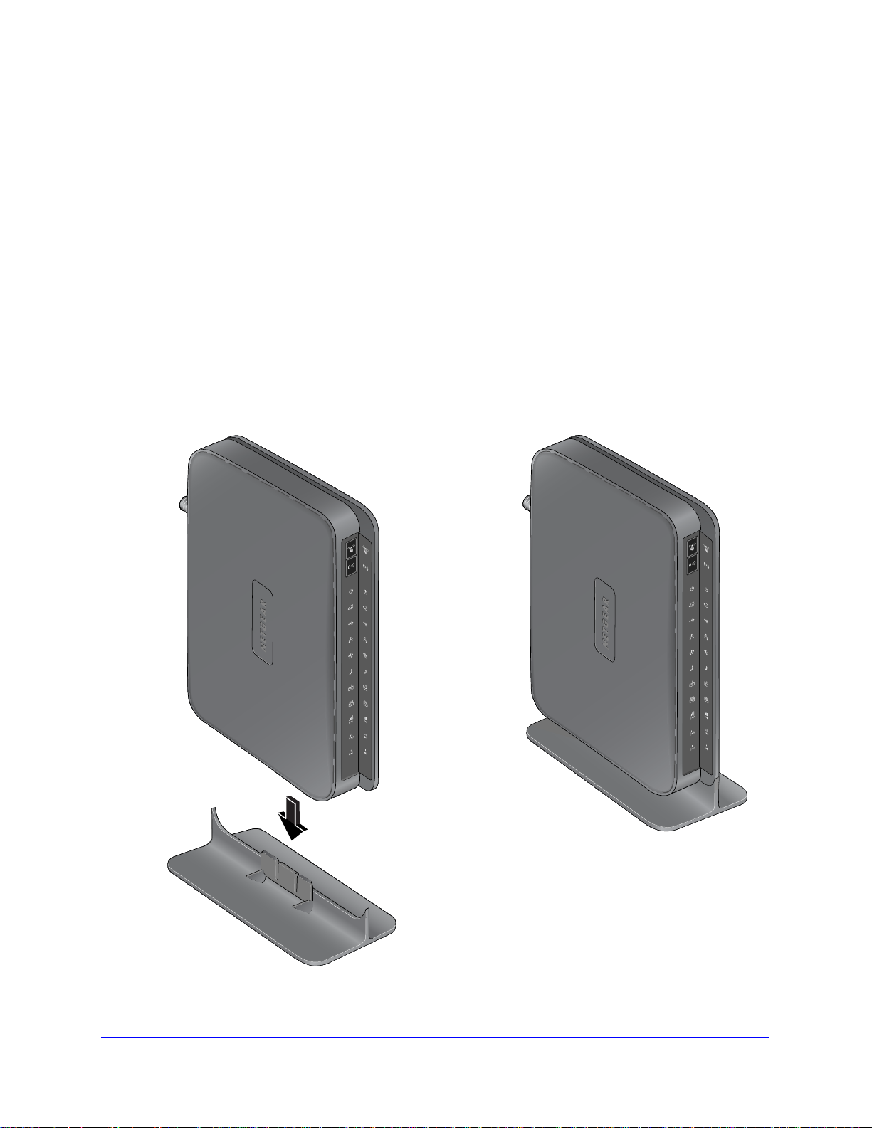
Router Stand
Since the Mobile V oice HSPA+ Broadband 11n Wireless Router is a vertical-only device, use
the stand to position your router upright.
nsert the tabs on the stand into the slot on the bottom of your router.
1. I
2.
Place your router near
you need for your home network.
The router needs to be located where you can receive a strong mobile broadban
while indoors if you are planning to connect to the Internet using mobile broadband.
an AC power outlet in a location where you can connect the cables
d signal
Figure 1.
Connecting to the Internet
7
Page 8
Mobile V oice HSP A+ Broadband 1 1n Wireless Router MVBR1210C
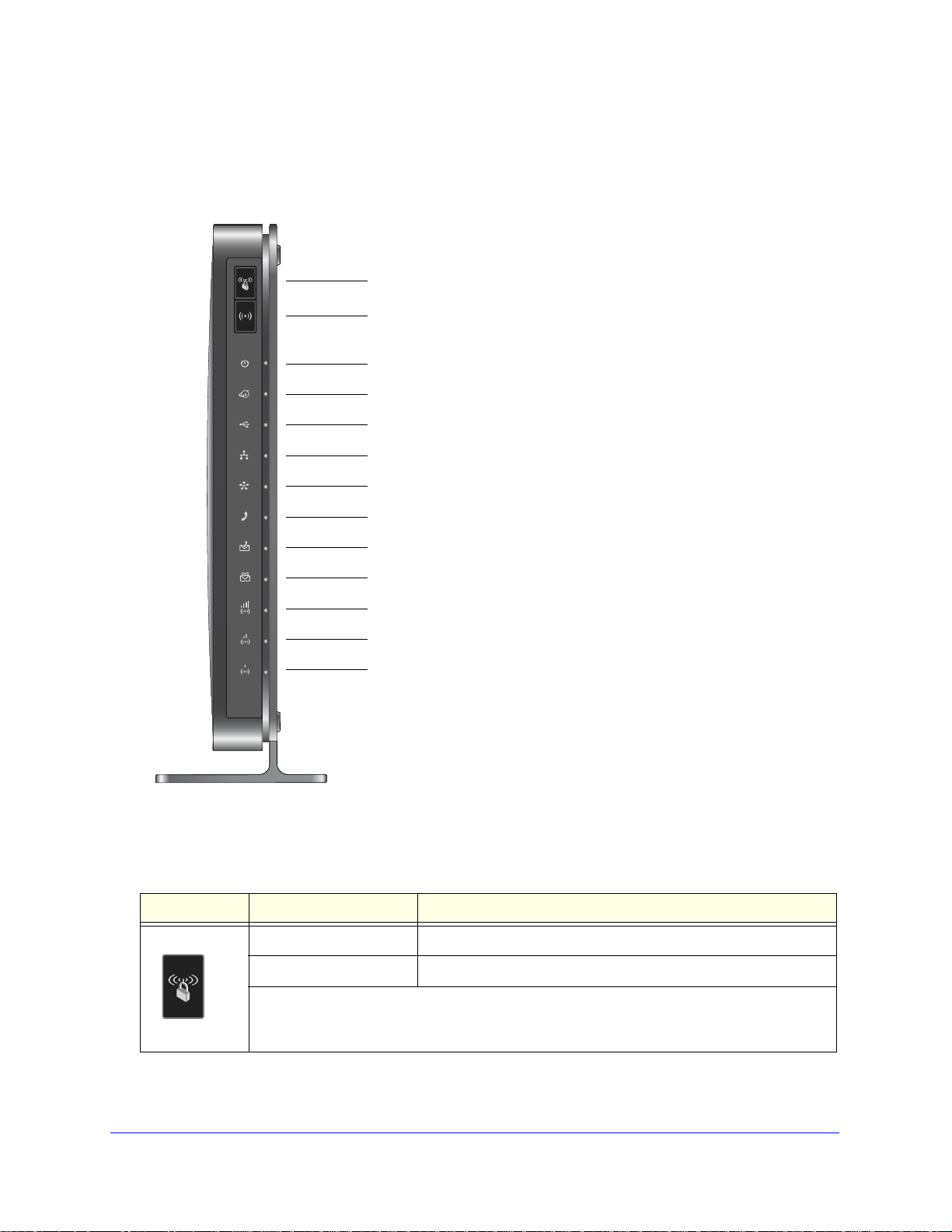
Power
Signal Quality (Excellent)
USB
Phone
WPS
Internet
LAN
WAN
WiFi
Signal Quality (Poor)
Signal Quality (Good)
SMS Message
Voice Mail
Router Front Panel
The router front panel contains control buttons and status LEDs. Use the LEDs to verify
status and connections.
Figure 2.
Table 1 describes each LED and button located on the front panel of the router.
Table 1. LED descriptions
LED Activity Description
WPS
Solid green WiFi has security enabled.
Blinking green WPS is running.
Press the WPS button
WPS-enabled devices. For more information about this function, see Use Push 'N' Connect
(WPS) to Configure Your Wireless Network on p
to open a 2-minute window for the router to connect with other
age 31.
Connecting to the Internet
8
Page 9
Mobile V oice HSP A+ Broadband 11n W ireless Router MVBR1210C
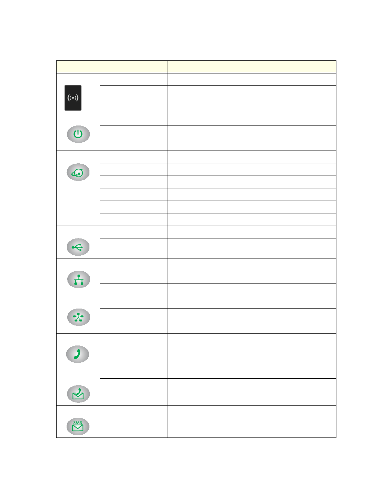
Table 1. LED descriptions (continued)
LED Activity Description
WiFi Blinking blue Data is being transmitted or received over the WiFi link.
Solid blue The WiFi local port is initialized.
Off The wireless access point is turned off.
Power Solid green The router is turned on and opera tin g normally.
Solid amber POST (power-on self-test) is in progress.
Off Power is not supplied to the router.
Internet Port
USB
LAN Ports
WAN Port
Solid green There is an Internet session.
Solid amber Traffic meter limit has been reached; traffic is blocked.
Blinking green Data is being transmitted over the Internet connection.
Blinking amber Traffic meter limit has been reached, but traffic is not blocked.
Blinking green and amber Failover occurred from WAN to mobile broadband.
Off No Internet connection is detected.
Solid green A USB port has detected a USB device.
Off No link is detected on this port.
Solid green The local Ethernet ports have detected wired links with computers.
Blinking Data is being transmitted or received.
Off No link is detected on these ports.
Solid green The Ethernet WAN port has detected an active link.
Blinking Data is being transmitted or received.
Off No link is detected on these ports.
Phone Port
Message
iting
Wa
SMS Message
Solid green The phone is off hook.
Off The phone is on hook.
Blinking green Voice mail is waiting.
Off There is no unread voice mail.
Solid green SMS messages are waiting.
Off There are no unread SMS messages.
Connecting to the Internet
9
Page 10
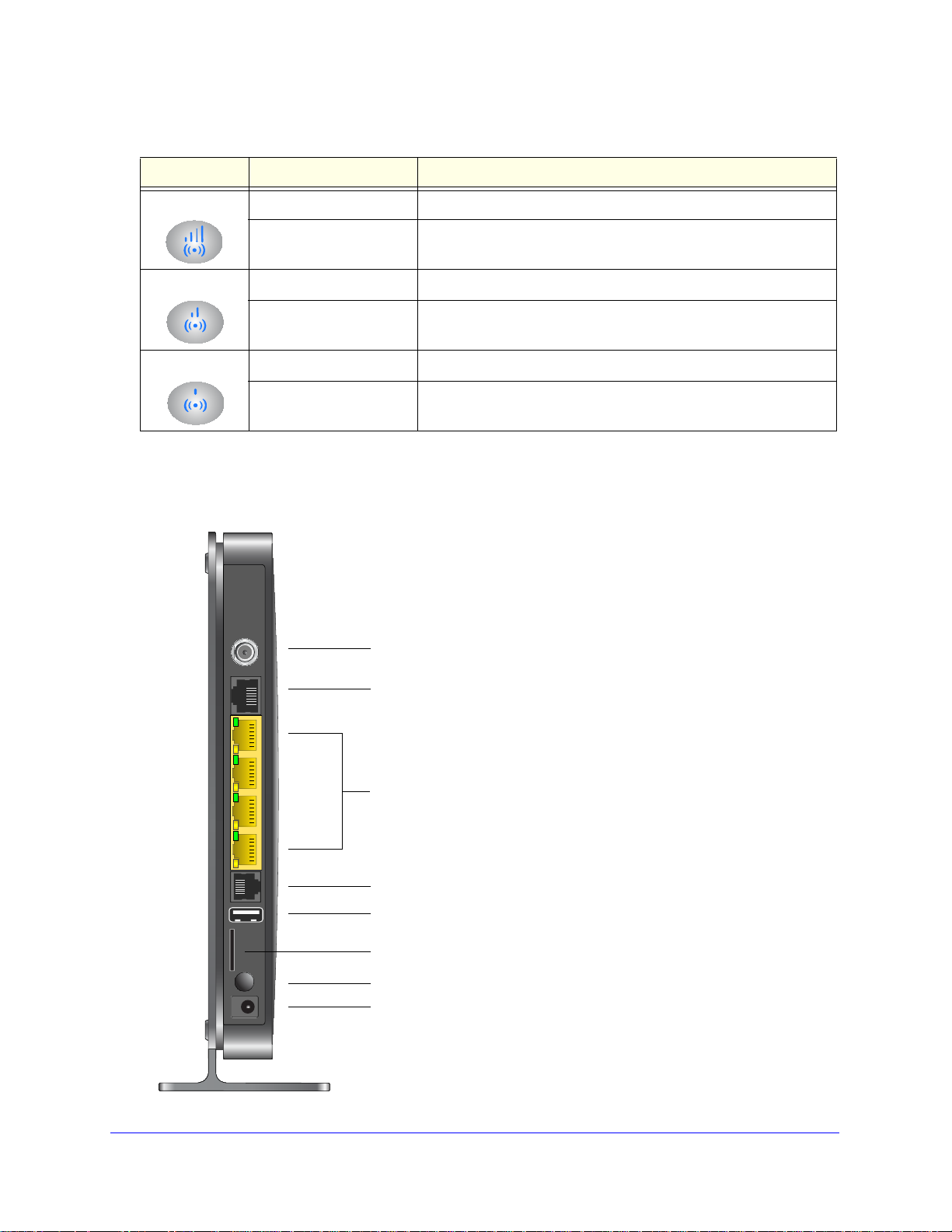
Mobile V oice HSP A+ Broadband 1 1n Wireless Router MVBR1210C
Ethernet LAN ports
Power On/Off button
Power adapter input
WAN port
Connector for optional external antenna
Slot for SIM card (if required by ISP)
USB port
Phone port
Table 1. LED descriptions (continued)
LED Activity Description
Signal Quality Solid blue Excellent coverage has been detected.
Signal Quality
Signal Quality
All Signal Quality LEDs
are off
Solid blue Good coverage has been detected.
All Signal Quality LEDs
are off
Solid blue Marginal coverage has been detected.
All Signal Quality LEDs
are off
No coverage has been detected.
No coverage has been detected.
No coverage has been detected.
Router Back Panel
The back panel of the router contains port connections.
Connecting to the Internet
10
Page 11
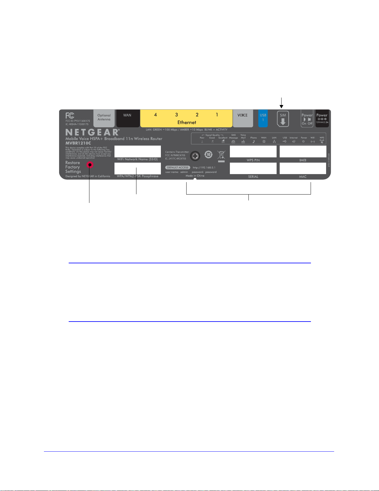
Mobile V oice HSP A+ Broadband 11n W ireless Router MVBR1210C
Restore
Factory
Router label
Router information
- Default access address
- Default user name and password
- WPS PIN
- IMEI or ESN number
- Serial number
- MAC address
Direction of SIM card insertion
with unique
SSID and
passphrase
Settings:
Press for
6 seconds.
Router Label
The label on the left side of the router shows the router’s MAC address, serial number,
security PIN, IMEI or ESN number, and factory default login information. It also contains the
SSID and passphrase that is unique to each router.
Note: Restore Factory Settings. Locate the small hole outlined in red on
the back of the router . Insert a p aper clip in to the hole and push for 6
seconds. Pressing the Restore Factory Settings button causes the
LED to blink briefly. After the button is held down for more than 6
seconds, the LED flashes AMBER, and then turns green as the
router resets to the factory defaults.
Connecting to the Internet
11
Page 12
Mobile V oice HSP A+ Broadband 1 1n Wireless Router MVBR1210C
Log In to Your Router
When you first connect to your router during installation, a Setup Wizard displays.
After the initial configuration, you can use your web bro
change its settings. Links to Knowledge Base and documentation are also available on the
router main menu.
Note: Your computer needs to be configured for DHCP. For help
configuring DHCP, refer to the documentation that came with your
computer.
When you have logged in, if you do not click Logout, after 5 minutes of no activity the router
automatically logs you out.
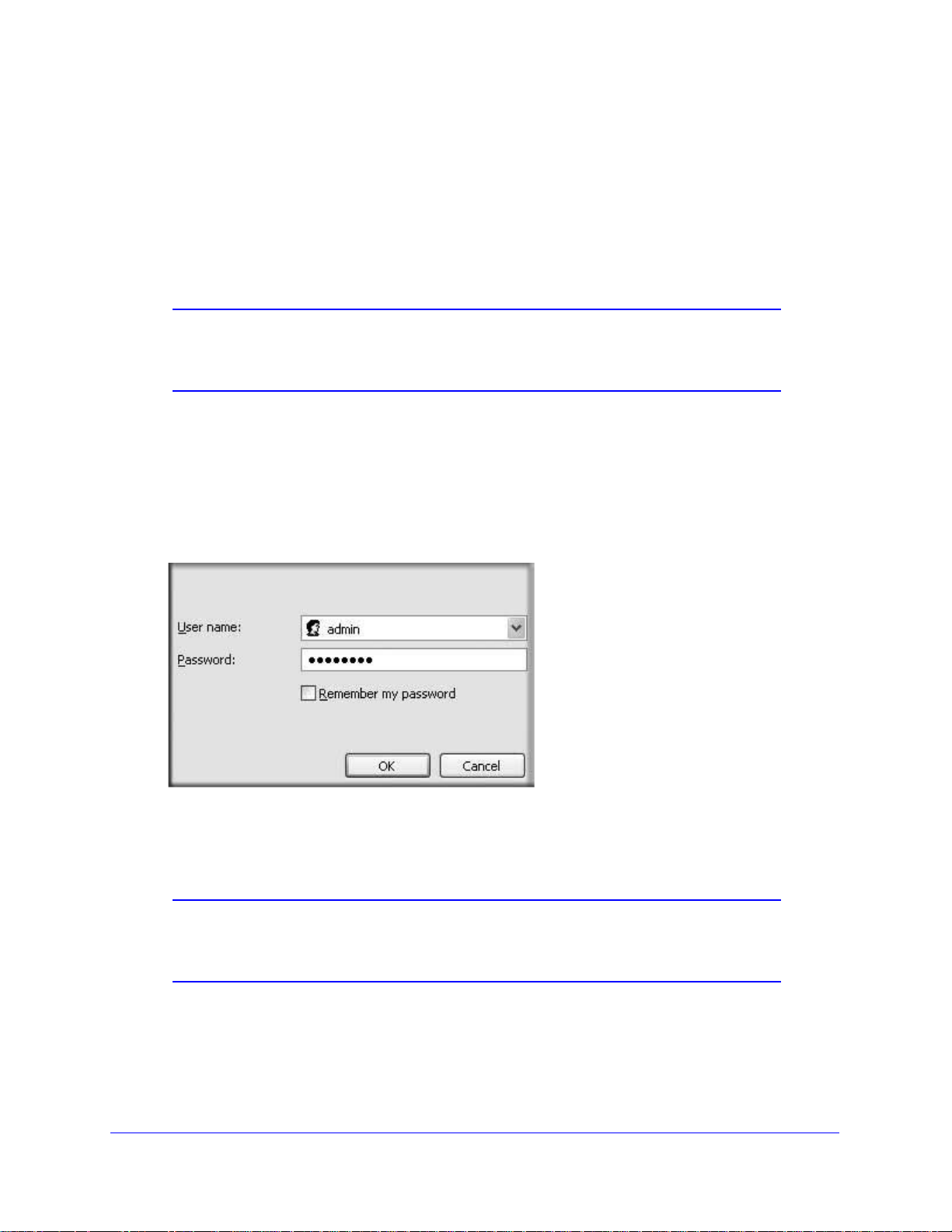
To log in to the router:
1. Type http://www
Enter or Return to display the login window.
.routerlogin.net in the address field of your browser, and then press
wser to log in to the router to view or
2. Enter admin for the user name and your password (or the default, password).
For information about how to change the password, see Change the Built-In Password on
page 70.
Note: If you do not remember your password, you can restore the router to
its factory default settings, which will reset the password. See
Factory Default Settings on page 108.
3. If the router has not been configured, the Smart Wizard screen
been configured, one of the following screens displays:
Connecting to the Internet
12
displays. After the router has
Page 13
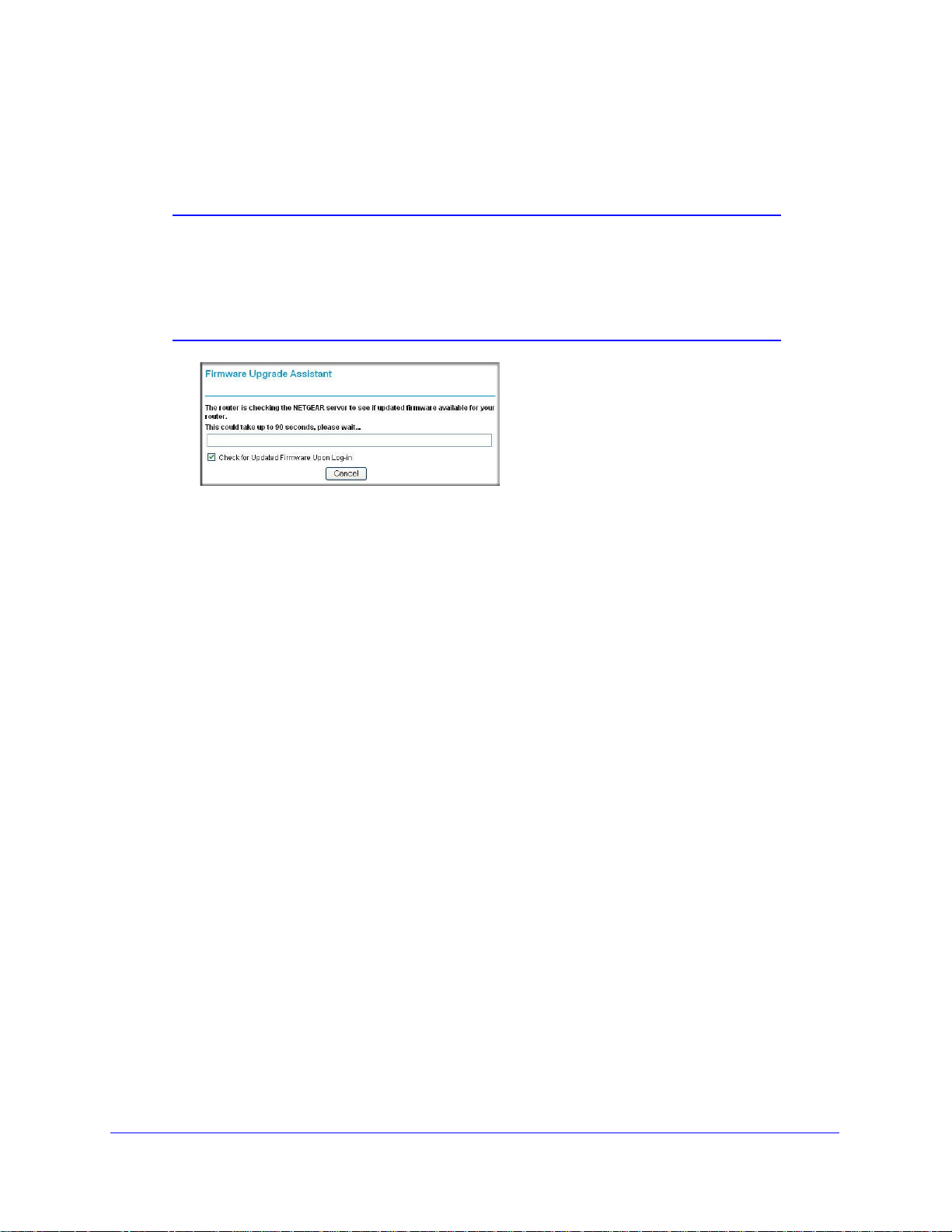
Mobile V oice HSP A+ Broadband 11n W ireless Router MVBR1210C
• Firmware Upgrade Assistant screen. After initial setup, the Firmware Upgrade
Assistant screen displays unless the Check for Updated Firmware Upon Log-in check
box is cleared.
Note: Y ou can disable this automatic checking and updating f eature during
future log-ins by clearing the Check for Updated Firmware Upon
Log-in check box, but NETGEAR recommends that you keep this
feature enabled to ensure that your router is using the latest updated
firmware.
• Router Status screen. The Router Status screen displays the current router
connection status. See Router Status on page 64.
You can use different methods to configure your router.
4.
•
Select Setup Wi
zard from the router menu to set up your Internet connection and
wireless network configuration. See Access the Setup Wizard after Installation on
page 14.
• Y ou can manually conf igure the router settings. See Manually Configure Y
Settings on pag
e 15.
our Internet
Connecting to the Internet
13
Page 14
Mobile V oice HSP A+ Broadband 1 1n Wireless Router MVBR1210C
Access the Setup Wizard after Installation
To access the Setup Wizard:
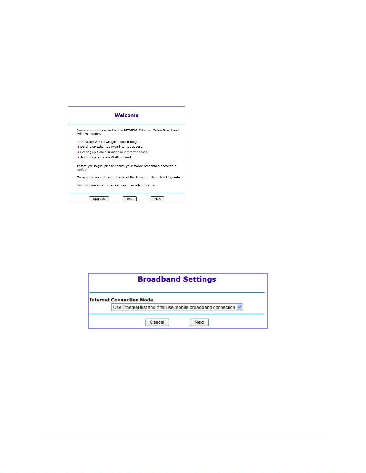
1. Log in to the router as describe
The Setup Wizard opens.
2. Click Next.
The Setup Wizard prompts you to set up your Internet connection and wireless network.
a. Select your Inte
• Use Ethernet first and if fail use mobile broadband connection
• Always us
• Always us
rnet connection mode:
e mobile broadband connection
e Ethernet connection
d in Log In to Your Router on page 12.
b. Click Next.
c. Select your
d. Click Done.
country and then your Internet service provider.
Connecting to the Internet
14
Page 15
Mobile V oice HSP A+ Broadband 11n W ireless Router MVBR1210C
Manually Configure Your Internet Settings
For you to connect to the network, an active broadband service account is required. Contact
your ISP for your user name, password, and the network name. You also need to configure
some or all of the settings described in the following sections, depending on how you have
chosen to connect to the Internet:
• Broadband Settings on page 15
•
Mobile Broadband Settings on p
• Ethernet Broadband Settings on page 19 (not
connection only)
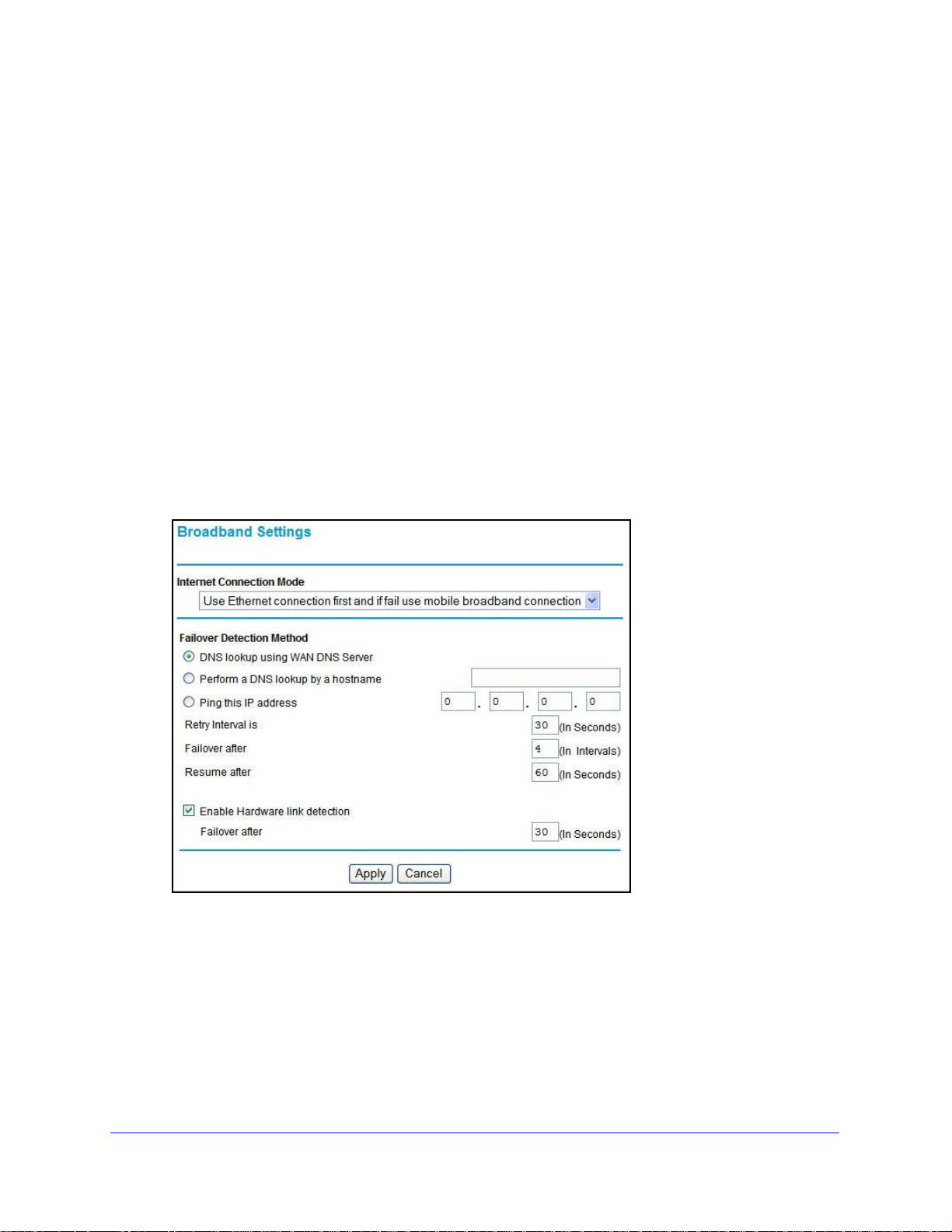
Broadband Settings
To manually configure your broadband Internet settings:
age 17 (not required if using Ethernet connection only)
required if using mobile broadband
1. Log in to the router as described in Log In to
2. From the main menu, select Broadband
3. Adjust the settings as needed based on your Internet connection. The fields in this screen
are described in Table 2.
4. The following buttons
• Apply. Apply the chan
• Cancel. Discard change
are available:
ges that you made.
s.
Your Router on page 12.
Settings.
Connecting to the Internet
15
Page 16

Mobile V oice HSP A+ Broadband 1 1n Wireless Router MVBR1210C
Table 2. Internet connection settings
Fields and check boxes Description
Internet Connection Mode The choices are:
• Always use an Ethernet connection (default)
• Use Ethernet first and if fail use
• Always use mobile broadband connection
mobi
le broadband connection
Failover Detection Method
1
Select the failover method, and enter the related information:
• DNS lookup using WAN DNS Server
• Perform a DNS lookup by a hostname
• Ping this IP address
1
Retry Interval is
Failover after
Resume after
Enter the retry interval.
1
Enter how many retry attempts to make before failing over.
1
Enter how long to wait for the primary link to be stabilized before
resuming use of the primary link.
Enable Hardware link detection When selected, the hardware detects when the Ethernet link is
dropped.
Enter when to failover when the Ethernet link is dropped. This is
endent of the DNS and Ping detection methods.
indep
1. This field is available only when the Internet connection mode is Use Ethernet first and if fail use
broadband connection.
Connecting to the Internet
16
Page 17
Mobile V oice HSP A+ Broadband 11n W ireless Router MVBR1210C
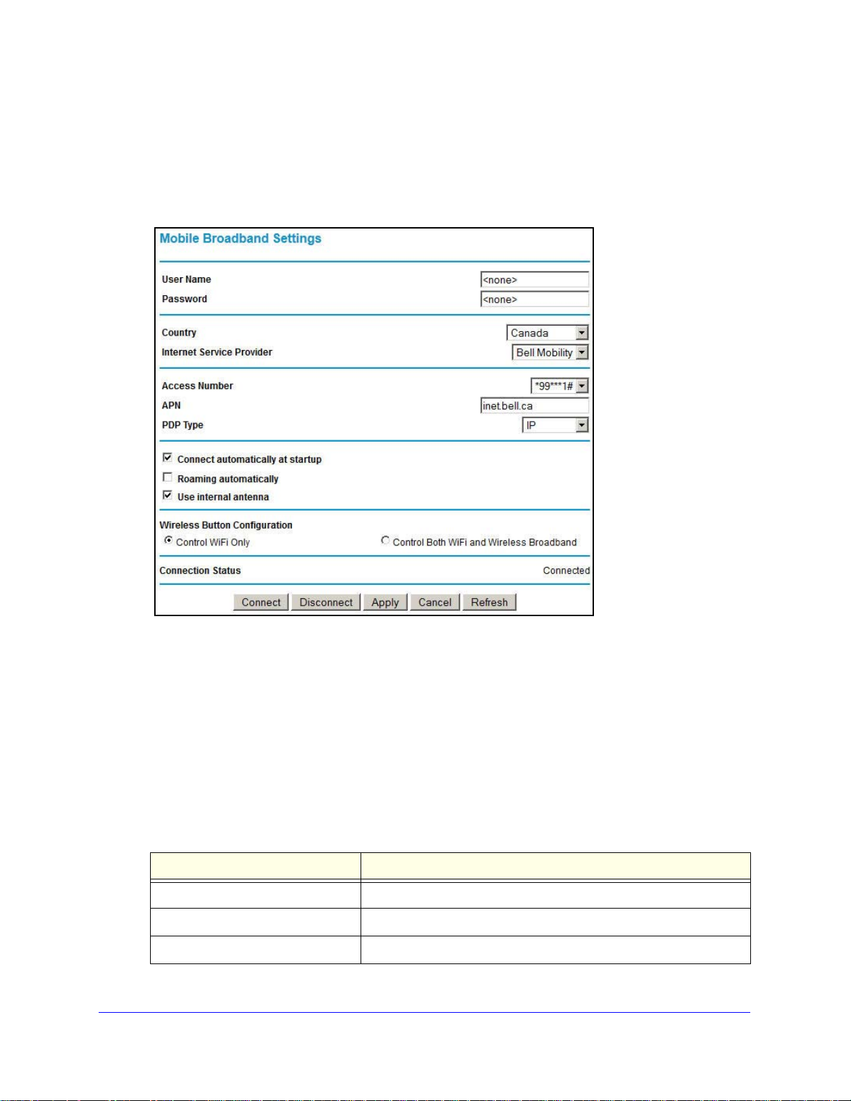
Mobile Broadband Settings
To manually configure your mobile broadband Internet settings:
1. Log in to the router as described in Log In to
2. From the main menu, select Mobile Broadb
and Settings.
Your Router on page 12.
3. Adjust the settings as needed based on your Internet connection. The fields in this screen
are described in Table 3.
4. Available buttons are:
Connect. Manu
•
• Disconnect. Disconn
• Apply. Apply the chan
• Cancel. Discard change
• Refresh. Update the
Table 3. Settings
Fields and check boxes Description
User Name Internet account login user name.
Password Internet account password for authentication.
Country Select your country from the drop-down list.
ally connect to the network.
ect from the current network.
ges that you made.
s.
connection status.
Connecting to the Internet
17
Page 18

Mobile V oice HSP A+ Broadband 1 1n Wireless Router MVBR1210C
Table 3. Settings
Fields and check boxes Description
Internet Service Provider Select your Internet service provider from the drop-down list.
Access Number The remote site’s phone number.
PIN code Pin code of the SIM card, where applicable.
APN Access point name.
PDP type Select the type of packet data protocol:
• IP
• PDP-IP
• PPP
• PPP-IP
Connect automatically at startup When this check box is selected, the modem automatica
to the network when powered up. This should be selected after login
information is provided.
Roaming automatically When this check box is selected, the unit might roam to any available
perator in range and might incur roaming charges.
o
Use internal antenna If this check box is selected, the router
rather than the external antenna.
Wireless Button Configuration Select the option to determine what happens when the WPS button
n the front panel is pressed.
o
ntrol Wi-Fi Only. Pressing the button toggles the WiFi function.
• Co
If WiFi is turned on, pressing the button turns off the WiFi. Pressing
it again turns on the WiFi. This function is available only if the WiF i
function is enabled. The wireless broadband function is unaffected.
trol Both Wi-Fi and Wireless Broadband. Pressing the push
• Con
button toggles both the WiFi function and wireless broadband at
the same time. If WiFi is turned on, pressing the button turns off the
WiFi. At the same time, the wireless broadband connection is
disconnected. If you press the button again, WiFi is turned on and
the router attempts to reestablish the wireless broadband
connection. Depending on the coverage, wireless broadband
coverage might or might not be connected successfully.
Connection status Current WAN port status.
will use the internal antenna
lly connects
Connecting to the Internet
18
Page 19
Mobile V oice HSP A+ Broadband 11n W ireless Router MVBR1210C
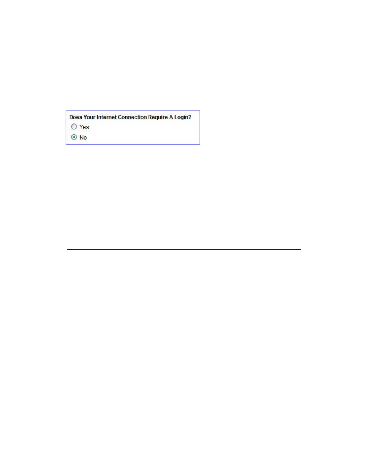
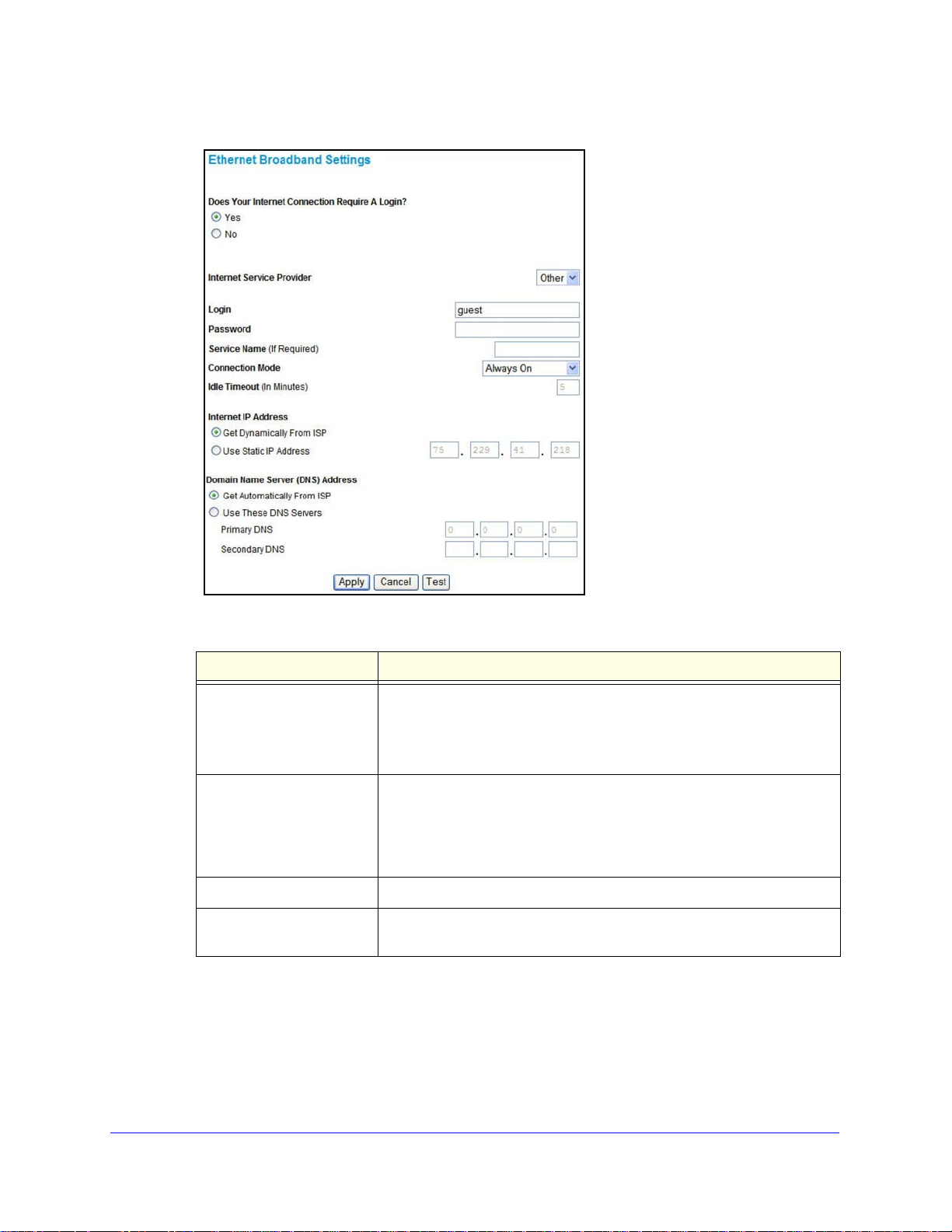
Ethernet Broadband Settings
To manually configure your Ethernet broadband Internet settings:
1. Log in to the router as described in Log In to
2. From the main menu, select Ethernet Broadband
Your Router on page 12.
Settings.
The following question displays at the top of the screen:
Select the option based on the type of account you have with your ISP.
• If you need to en
ter login information every time you connect to the Internet, or you
have a PPPoE account with your ISP, select Yes.
• Otherwise, select No.
T
hen fill out the appropriate screen.
For details, see one of the following:
• step a, Login required:
• step b, Login not required:.
Note: If you have installed PPP software such as WinPoET (from
Earthlink) or Enternet (from PacBell), then you have PPPoE. Select
Yes. After selecting Yes and configuring your router, you do not
need to run the PPP software on your computer to connect to the
Internet.
a. Login required:
Adjust the settings as needed based on your Internet connection. The fields in this
screen are
described in Table 4.
Connecting to the Internet
19
Page 20
Mobile V oice HSP A+ Broadband 1 1n Wireless Router MVBR1210C
Table 4. Ethernet broadband settings when login required
Fields and check boxes Description
Internet Service Provider Select the service provided by your ISP.
• Other (PPPoE) is the most common.
• PPTP is used in Austria and other European countries.
• Telstra BigPond is for Australia only.
Login This is usually the name that you use in your emai
if your main mail account is JerAB@ISP.com, then type JerAB in this field.
Some ISPs (such as Mindspring, Earthlink, and T-DSL) require that you
use your full email
email address, then type it in the Login field.
Password Type the password that you use to log in to your ISP.
Service Name (If Required) If your ISP provided a service name, enter
left blank.
address when you log in. If your ISP requires your full
l
it here
. Otherwise, this can be
address. For example,
Connecting to the Internet
20
Page 21

Mobile V oice HSP A+ Broadband 11n W ireless Router MVBR1210C
Table 4. Ethernet broadband settings when login required (continued)
Fields and check boxes Description
Connection Mode Set the connection mode to Dial on Demand, Always On, or Manually
Connect.
• With the default setting, Dial on
automatically starts when there is outbound traffic to the Internet, and it
automatically terminates if the connection is idle based on the value in
the Idle Timeout field.
• When the connection mode is set to Always
connection automatically starts when the computer boots up, but the
connection does not time out. The router keeps trying to bring up the
connection if it is disconnected for some reason.
• If you select Man
screen and click the Connect button to connect to the Internet. The
manual connection does not time out, and you have to click the
Disconnect button on the Router Status screen to disconnect it.
ually Connect, you need to go to the Router Status
Demand, a PPPoE connection
On, the PPPoE
Idle Timeout (In Minutes) An idle Internet connection is terminated
value is zero (0), then the router keeps the connection alive by
reconnecting immediately whenever the connection is lost.
Internet IP Address If you log in to your service or your ISP did no
address, the router finds an IP address for you automatically when you
connect. Select Get Dynamically from ISP.
If you have a fixed (static, permanent) IP add
you with an IP address. Select Use Static IP Address, and type the IP
address.
Domain Name Server
NS) Address
(D
The DNS server is used to look up site addresses based on their names.
• If your ISP gave you one or two
DNS Servers, and type the primary and secondary addresses.
• Otherwise, select Get Automaticall
Note: If
likely that your DNS servers are not set up correctly. You should contact
your ISP to get DNS server addresses.
you get “Address not found” errors when you go to a website, it is
after this time period. If this
t provide you with a fixed IP
ress, your ISP has provided
DNS addresses, select Use These
y From ISP.
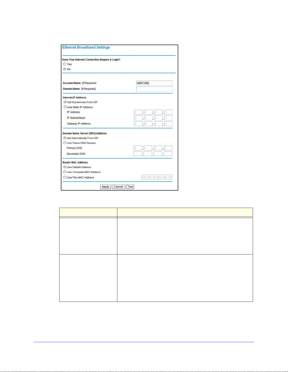
b. Login not required:
Adjust the settings as needed based on your Internet connection. The fields in this
en are described in Table 5.
scre
Connecting to the Internet
21
Page 22
Mobile V oice HSP A+ Broadband 1 1n Wireless Router MVBR1210C
Table 5. Ethernet broadband settings fields when login not required
Fields and check boxes Description
Account Name (If Required) This is also known as the host name or system name.
For most users, type your account name or
example, if your main mail account is JerAB@ISP.com, then type
JerAB in this field.
If your ISP has given you a specific host name, then
example, CCA7324-A).
Domain Name (If Required) For most users, you can leave this field blank, unless required by your
You can type the domain name of your ISP. For example, if your
ISP.
ISP’s mail server is mail.xxx.yyy.zzz, you would type xxx.yyy.zzz as the
domain name.
If you have a domain name given to you by your ISP , type it in this field.
r
example, Earthlink Cable might require a host name of home, and
(Fo
Comcast sometimes supplies a domain name. )
If you have a cable modem, this i
s usually the workgroup name.
user name in this field. For
type it (for
Connecting to the Internet
22
Page 23

Mobile V oice HSP A+ Broadband 11n W ireless Router MVBR1210C
Table 5. Ethernet broadband settings fields when login not required (continued)
Fields and check boxes Description
Internet IP Address If you log in to your service or your ISP did not provide you with a fixed
IP address, the router finds an IP address for you automatically when
you connect. Select Get Dynamically From ISP.
If you have a fixed (or static IP) address, your ISP has provided you
th the required information. Select Use Static IP Address, and type
wi
the IP address, subnet mask, and gateway IP address in the correct
fields.
For example:
• IP Ad
• Subnet Mask. 255.255.255.0
• Gateway I
dress. 24.218.156.183
P Address. 24.218.156.1
Domain Name Server (DNS)
dress
Ad
Router MAC Address Your computer’s local address is
The DNS server is used to look up site addresses based on their
names.
• If your ISP gave you one or two DNS addresses, select Use Th
DNS Servers, and type the primary and secondary add resses.
• Otherwise, select Get Automatically From ISP.
Note: If
is likely that your DNS servers are not set up correctly. You should
contact your ISP to get DNS server addresses.
This is also referred to as the computer’s MAC (Media Access Control)
address.
• Usually, select Use
• If your ISP requires MAC authentication, then select either Use
Computer MAC Address to disguise the router’s MAC address with
the computer’s own MAC address, or select Use This MAC Address
and manually type the MAC address for a different computer.
The format for the MAC address is XX:XX:XX:XX:XX:XX
might be changed if Use Computer MAC Address is selected once a
value has already been set in the Use This MAC Address selection.
3. The following buttons are available:
• Apply. Apply the
• Cancel. Discard
• Te
st. Connect to the NETGEAR website. If you connect successfully, your settings
changes that you made.
changes.
work, and you can click Logout to exit these screens.
ese
you get “Address not found” errors when you go to a website, it
its unique address on your network.
Default MAC Address.
. This value
Connecting to the Internet
23
Page 24

2. Wireless Network Configuration
For a wireless connection, the SSID (also known as the wireless network name) and the wire less
security settings need to be the same for the router and wireless computers or wireless
adapters. NETGEAR strongly recommends that you use wireless security.
The router is preconfigured with WPA-PSK/WPA2-PSK mixed mode and uses a unique SSID
and passphrase. This information is printed on the label on the bottom of the router. Use this
information to setup your WiFi computer and devices.
This chapter incudes the following sections:
• Plan Your Wireless Network
• Manually Configure Your Wireless Settings
• Use Push 'N' Connect (WPS) to Configure Your Wireless Network
• SIM Card PIN Code
• SIM Card Modem Unlock Code
2
Note: Computers can connect wirelessly at a range of several hundred
feet. If you do not use wireless security , this can allow others out side
your immediate area to access your network.
24
Page 25

Mobile V oice HSP A+ Broadband 11n W ireless Router MVBR1210C
Plan Your Wireless Network
For compliance and compatibility between similar products in your area, the operating
channel and region need to be set correctly.
To configure the wireless network, you can eithe
use Wi-Fi Protected Setup (WPS) to automatically set the SSID and implement WPA/WPA2
security.
o manually configure the wireless settings, you need to know the following:
• T
- SSID. Th
he wireless mode (802.11n, 802.11g, or 802.11b) that each wireless adapter
- T
supports.
- W
ireless security option. To successfully implement wireless security, check each
wireless adapter to determine which wireless security option it supports.
See Manually Configure Your Wireless Settings o
• Pu
sh 'N' Connect (WPS) implements WP A/W P A2 wi reless security on the router and your
wireless computer or device at the same time. The wireless computer or device needs to
be compatible with WPS.
See Use Push 'N' Connect (WPS) to Configure Your Wireless Network on p
e default SSID for the router is NETGEAR-3G.
r specify the wireless settings, or you can
n page 27.
age 31.
Wireless Placement and Range Guidelines
The range of your wireless connection can vary significantly based on the physical placement
of the router. The latency , data throug hput performance, and notebook power consumption of
wireless adapters also vary depending on your configuration choices.
For best results, place your router according to the following guidelines:
• Near the
• In an
have line-of-sight access (even if through walls).
• A
way from sources of interference, such as microwave ovens and 2.4 GHz cordless
phones.
• A
way from large metal surfaces.
• Put the
antenna in a horizontal position to provide the best up-and-down coverage.
• If using
frequency channels to reduce interference. The recommended channel spacing between
adjacent access points is 5 channels (for example, use Channels 1 and 6, or 6 and 11).
The time it takes to establish a wireless connection can vary depending on both you r security
settings
encryption can consume more battery power on a notebook computer.
center of the area in which your computers will operate.
elevated location, such as a high shelf, where the wirelessly connected computers
antenna in a vertical position to provide the best side-to-side coverage. Put the
multiple access points, it is better if adjacent access points use different radio
and placement. WEP connections can take slightly longer to establish. Also, WEP
Wireless Network Configuration
25
Page 26
Mobile V oice HSP A+ Broadband 1 1n Wireless Router MVBR1210C
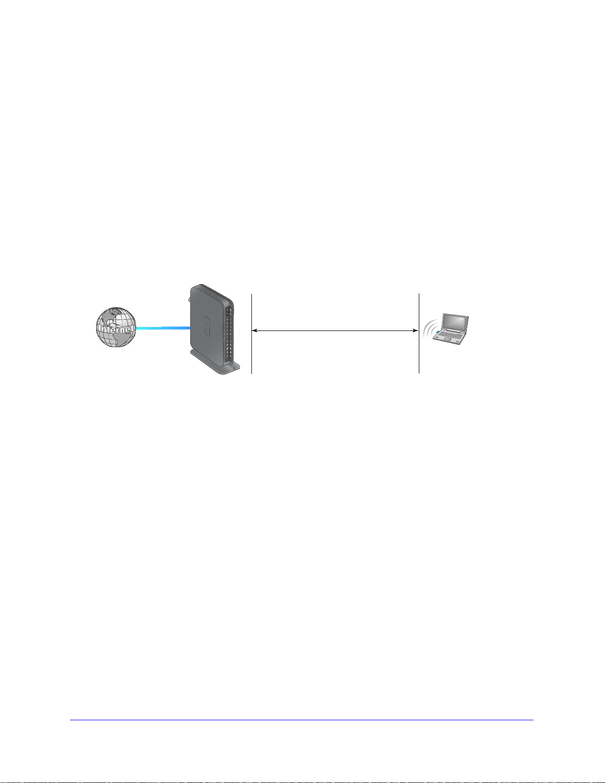
Wireless Data
Security Options
Range: up to 300 feet radius
1) Open system: easy but no security
2) MAC access list: no data security
3) WEP: security but some performance impact
4) WPA-PSK: strong security
5) WPA2-PSK: very strong security
MVBR1210C
Wireless Security Options
Indoors, computers can connect over 802.11n wireless networks at a maximum range of up
to 300 feet. Such distances can allow others outside your immediate area to access your
network.
Unlike wired network data, your wireless data tr
ansmissions can extend beyond your walls
and can be received by anyone with a compatible adapter. For this reason, use the security
features of your wireless equipment. The Mobile Voice HSPA+ Broadband 11n Wireless
Router provides highly effective security features, which are covered in detail in this chapter.
Deploy the security features appropriate to your needs.
Each router is preconfigured for WP A-PSK/WPA2-PSK mixed mode and comes with
a unique
SSID and passphrase.
There are several ways you can enhance the security of your wireless network:
Figure 3. Wireless security
• Restrict access based on MAC address. You can allow only trusted computers to
connect so that unknown computers cannot wirelessly connect to the router. Restricting
access by MAC address adds an obstacle against unwanted access to your network, but
the data broadcast over the wireless link is fully exposed.
• Turn off the broadcast of the wireless network name (SSID). If
you disable broadcast
of the SSID, only devices that have the correct SSID can connect. This nullifies wireless
network “discovery” feature of some products, such as Windows XP, but the data is still
exposed.
• WEP. Wired Equivale
nt Privacy (WEP) data encryption provides data security. WEP
Shared Key authentication and WEP data encryption block all but the most determined
eavesdropper. This data encryption mode has been superseded by WPA-PSK and
WPA2-PSK.
• WPA-PSK (TKIP), WP A2-PSK (AES).
key to perform authentication and generate the initial data encryption keys. The very
strong authentication along with dynamic per frame rekeying of WPA makes it virtually
Wi-Fi Protected Access (WPA) uses a pre-shared
impossible to compromise.
Wireless Network Configuration
26
Page 27
Mobile V oice HSP A+ Broadband 11n W ireless Router MVBR1210C
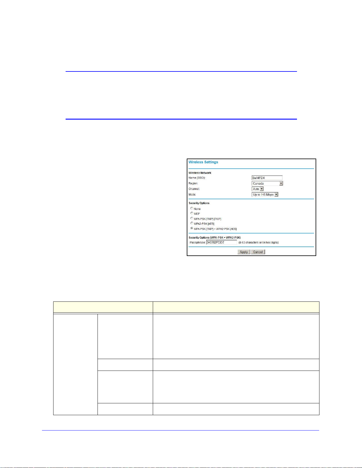
Manually Configure Your Wireless Settings
Note: If you use a wireless computer to change the wireless network
name (SSID) or wireless security, you will be disconnected when
you click Apply. To avoid this occurrence, connect your computer
directly to the router with an Ethernet cable while you are making
changes.
To view or manually configure the wireless settings:
1. Log in to the router as described in Log In to
2. Select Wire
less Settings from the main
Your Router on page 12.
menu.
The settings for this screen are
explained in Table 6.
3. Select the region in which
the router will
operate.
4. For initial configuration and test,
leave the
other settings unchanged.
5. To save your changes, click Apply.
6.
Configure and test your computers for
less connectivity.
wire
Set up your wireless computers with the
same SSID and
wireless security settings as your router. Check that they have a wireless
link and are able to obtain an IP address by DHCP from the router. If there is interference,
adjust the channel.
Table 6. Wireless settings
Settings Description
Wireless
Network
Name (SSID) The SSID is also known as the wireless network name. Enter a
32-character (maximum) name in this field. This field is
case-sensitive.
When there is more than one wireless network, SSIDs provide a
n
s for separating the traffic. To join a network, a wireless
mea
computer or device needs to use the SSID.
Region The location where the router is used.
Channel The wireless channel used by the gateway
Do not change the channel unless you experience interference
(shown by
you might need to try different channels to see which works best.
Mode The default is Up to 145 Mbps.
Wireless Network Configuration
lost connections or slow data transfers). If this happens,
27
. The default is Auto.
Page 28

Mobile V oice HSP A+ Broadband 1 1n Wireless Router MVBR1210C
Table 6. Wireless settings (continued)
Settings Description
Security Options None Use this setting to establish wireless connectivity before
implementing wireless security. NETGEAR strongly recommends that
you implement wireless security.
WEP Use encryption keys and data encryption for data security. You can
ct 64-bit or 128-bit encryption. See Configure WEP on page 28.
sele
WPA-PSK (TKIP) Allow only computers configured with WP
See Configure WPA, WPA2, or WPA + WPA2 on page 30.
WPA2-PSK (AES) Allow only computers configured with WPA2 to connect to the router.
See Configure WPA, WPA2, or WPA + WPA2 on p
WPA-PSK (TKIP) +
WPA2-PSK (AES)
Allow computers configured with either WPA-PSK or WPA2-PSK
security to connect to the router. See Configure WPA, WP A2, or WPA
+ WPA2 on
Configure WEP
Note: If you use a wireless computer to configure wireless security
settings, you will be disconnected when you click Apply.
Reconfigure your wireless computer to match the new settings, or
access the router from a wired computer to make further changes.
T o configure WEP data encryption:
1. Log in to the ro
2. From t
he main menu, select Wireless Settings to display the Wireless Settings screen.
uter as described in Log In to Your Router on page 12.
A to connect to the router.
age 30.
page 30.
Wireless Network Configuration
28
Page 29
Mobile V oice HSP A+ Broadband 11n W ireless Router MVBR1210C
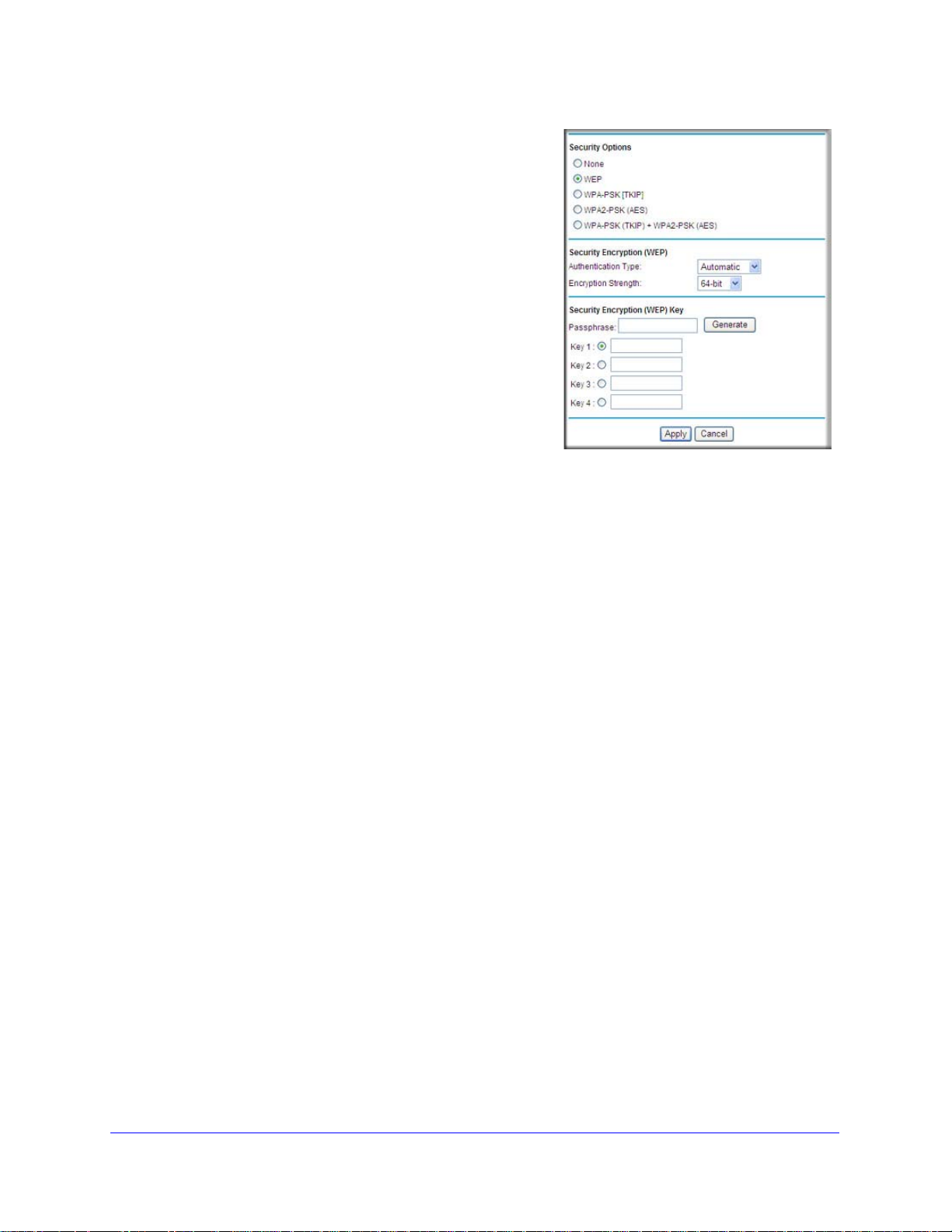
3. In the Security Options section, select the WEP
(Wired Equivalent Privacy) radio button:
4. Select the Authentication Type setting: Automatic,
Open System, or Shared Key. The default is Open
System.
Note: The authentication is separate from the
data en
cryption. You can select authentication
that requires a shared key, but still leaves data
transmissions unencrypted. Security is stronger
if you use both the Shared Key and WEP
encryption settings.
5. Select
•
• 128-bit. Enter 26
the Encryption Strength setting:
64-bit. Enter 10 hexadecimal digits (any
combinat
ion of 0–9, a–f, or A–F).
hexadecimal digits (any combination of 0–9, a–f, or A–F).
6. Enter the encryption keys. You can manually or automatically program the four data
encryption
keys. These values need to be identical on all computers and access points in
your network:
• Passphrase. T
o use a passphrase to generate the keys, enter a passphrase, and
click Generate. This automatically creates the keys. Wireless stations need to use the
passphrase or keys to access the router.
Note: Not all wireless adapters support passphrase key generation.
• Key 1
–Key4. These values are not case-sensitive. You can manually enter the four
data encryption keys. These values need to be identical on all computers and access
points in your network. Enter 10 hexadecimal digits (any combination of 0
–F).
A
7. Select which of the four keys will be the
default.
–9, a–f, or
Data transmissions are always encrypted using the default key. The other keys can be
us
ed only to decrypt received data. The four entries are disabled if WPA-PSK or WPA
authentication is selected.
8. Click Appl
y to save your settings.
Wireless Network Configuration
29
Page 30

Mobile V oice HSP A+ Broadband 1 1n Wireless Router MVBR1210C
Configure WPA, WPA2, or WPA + WPA2
Both WPA and WPA2 provide strong data security. WPA with TKIP is a software
implementation that can be used on Windows systems with Service Pack 2 or later, WPA2
with AES is a hardware implementation; see your device documentation before implementing
it. Consult the product documentation for your wireless adapter for instructions for configuring
WPA settings.
Note: If you use a wireless computer to configure wireless security
settings, you will be disconnected when you click Apply. If this
happens, reconfigure your wireless computer to match the new
settings, or access the router from a wired computer to make further
changes.
To configure WPA or WPA2 in the router:
1. Log in to the ro
2. Select W
3. On th
ireless Settings from the main menu.
e Wireless Setting screen, select the radio button for the WPA or WPA2 option of your
uter as described in Log In to Your Router on page 12.
choice.
4. Fo
5. T
r WPA-PSK or WPA2-PSK, enter the passphrase.
o save your settings, click Apply .
Wireless Network Configuration
30
Page 31

Mobile V oice HSP A+ Broadband 11n W ireless Router MVBR1210C
WPS button
Use Push 'N' Connect (WPS) to Configure Your Wireless Network
For you to use Push 'N' Connect, your wireless computers or devices need to support Wi-Fi
Protected Setup (WPS). Compatible equipment usually has the
can configure the network name (SSID) and set up WP
router and the wireless computer or device at the same time.
A/WPA2 wireless security for the
WPS symbol on it. WPS
Here are some considerations to consider wh
wireless network:
• NET
• If your wireless network will include a combination of W
GEAR’s Push 'N' Connect feature is based on the WPS standard. All other
W
iFi-certified and WPS-capable products should be compatible with NETGEAR product s
that implement Push 'N' Connect.
non-WPS-capable devices, NETGEAR suggests that you set up your wireless network
and security settings manually first, and use WPS only for adding WPS-capable devices.
en planning on
using WPS to configure your
PS-capable devices and
WPS Button
Any wireless computer or wireless adapter that will connect to the router wirelessly is a client.
The client needs to support a WPS button and needs to have a WPS configuration utility,
such as the NETGEAR Smart Wizard or Atheros Jumpstart.
To use the router WPS button to add a WPS client:
1. Log in to the router as described in Log In to
2. On the router main menu, select Add
WPS Clie
By default, the Push Button
(recommended) radio button is
selected.
nt, and then click Next.
Your Router on page 12.
3. Either click the onscreen button or
press the WPS
the router.
The router tries to communicate with the client (the computer that wants to join the
network) f
4. Go to
5. Go back to the
the client wireless computer, and run a WPS config
instructions to click a WPS button.
button on the front of
or 2 minutes.
router screen to check for a message.
Wireless Network Configuration
31
uration utility. Follow the utility’s
Page 32
Mobile V oice HSP A+ Broadband 1 1n Wireless Router MVBR1210C
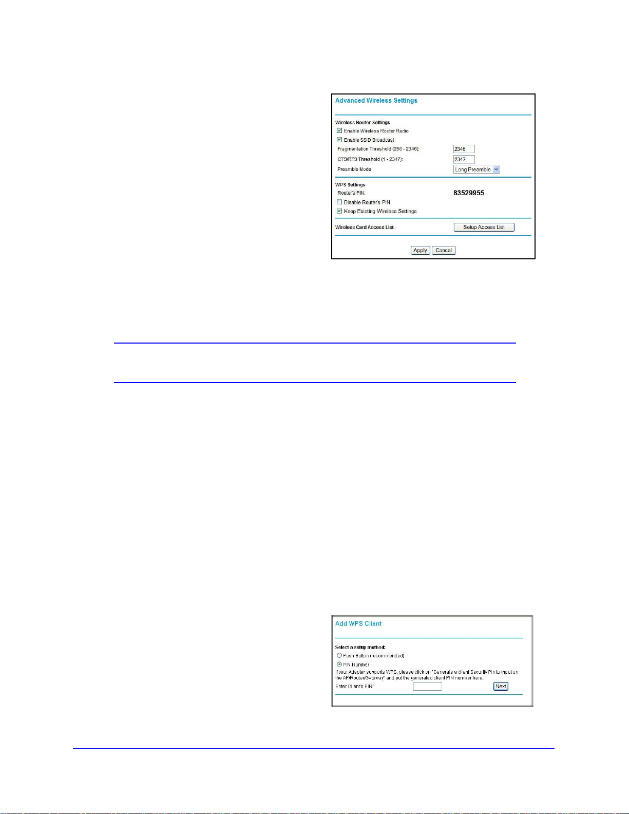
A message displays confirming that the
client was added to the wireless network.
The router generates an SSID and
implements WP A/WPA2 wireless security.
The router will keep these wireless
settings unless you change them or you
clear the Keep Existing Wireless
Settings check box in the Advanced
Wireless Settings screen.
6. Note the new SSID and WPA/WPA2
password for the wireless network. You can
view these settings in the Wireless Settings
screen. See Manually Configure Your
Wireless Settings on pag
e 27.
To access the Internet from any computer connected to your router, launch a browser such
as Microso
ft Internet Explorer or Mozilla Firefox. You should see the router’s Internet Port
LED blink, indicating communication to the ISP.
Note: If no WPS-capable client devices are located during the 2-minute
time frame, the SSID does not change, and no security is set up.
WPS PIN Entry
Any wireless computer or device that will connect to the router wirelessly is a client. The
client needs to support a WPS PIN and needs to have a WPS configuration utility, such as
the NETGEAR Smart Wizard or Atheros Jumpstart.
The first time you add a WPS client, make sure that the Keep Exis
ting W
check box on the Advanced Wireless Settings screen is cleared. This is the default setting for
the router, and allows it to generate the SSID and WPA/WPA2 security settings when it
implements WPS. After WPS is implemented, the router automatically select s this check box
so that your SSID and wireless security settings stay the same if other WPS devices are
added later.
To use a PIN to add a WPS client:
1. Log in to the router as describe
d in Log In to Your Router on page 12.
2. On t he router main menu, select Add WPS
Clien
t (computers that will connect
wirelessly to the router are clients), and
then click Next. The Add WPS Client
screen displays.
ireless Settings
3. Select the PI N Number radio button.
Wireless Network Configuration
32
Page 33

Mobile V oice HSP A+ Broadband 11n W ireless Router MVBR1210C
4. Go to the client wireless computer. Run a WPS configuration utility. Follow the utility’s
instructions to generate a PIN. Take note of the client PIN.
5. In the rout
• The ro
er Add WPS Client screen, enter the client PIN number, and then click Next.
uter tries to communicate with the client for 4 minutes. If no WPS clients
connect during this time, the router wireless settings do not change.
• The ro
uter WPS screen confirms that the client was added to the wireless network.
The router generates an SSID and implements WPA/WPA2 wireless security.
6. Note
the new SSID and WP A/WPA2 password for the wireless network. You can view these
settings in the Wireless Settings screen. See Manually Configure Your Wireless Settings on
page 27.
To access the Internet from any computer con
nected to your router, launch an Internet
browser such as Mozilla Firefox. You should see the router’s Internet LED blink.
Add Wireless Computers That Do Not Support WPS
If you set up your network with WPS, and now you want to add a computer that does not
support WPS, you need to manually configure that computer. For information about how to
view the wireless settings for the router, see Manually Configure Your Wireless Settings on
page 27.
Because WPA randomly creates the SSID and WPA/WPA2 keys, they might be difficult to
ype or remember (that is one reason why the network is so secure). You can change the
t
wireless settings so that they are easier for you to remember. If you do that, then you will
need to set up the WPS-compatible computers again.
Note: Making these changes will cause all wireless computers to be
disconnected from network. You will then have to set them up with
the new wireless settings.
To change wireless settings for the network:
1. Use an Ethern
et cable to connect a computer to the router. That way you will not get
disconnected when you change the wireless settings.
2. Log in to the rout
Settings on p
3. Ma
ke the following changes:
• Change
• On t
he WP A/PSK + WPA2/PSK screen, select a passphrase.
• Make sure tha
er, and select Wireless Settings (see Manually Configure Your Wireless
age 27).
the wireless network name (SSID) to a meaningful name.
t the Keep Wireless Settings check box is selected in the Advanced
Wireless Settings screen so that your new settings will not be erased if you use WPS.
4. Click App
ly so that your changes take effect. Write down your settings.
All existing wireless clients are disassociated a
nd disconnected from the router.
Wireless Network Configuration
33
Page 34

Mobile V oice HSP A+ Broadband 1 1n Wireless Router MVBR1210C
PIN Code
5. For the non-WPS device s that you want to connect, open the networking utility, and follow
the utility’s instructions to enter the security settings that you selected in Step 3 (the SSID,
WPA/PSK + WPA2/PSK security method, and passphrase).
6. For the WPS devices that you wan t to connect, follow the procedure in WP
page 31 or WPS PIN Entry on page 32.
settings that you configured in Step 3 are broadcast
The
can connect to the router.
to the WPS devices so that they
S Button on
SIM Card PIN Code
Some SIM cards might have a PIN code associated with them. Without the PIN code, you will
not be able to access the Internet. This status appears when a PIN is required, but has not
yet been entered.
To enter the PIN code:
1. Log in to the router and on the main menu under Advanced, select Mobile Broadband
Settings.
2. Enter th e PIN code.
Check with your service
provider if you do no
t know the modem unlock code.
3. Click Apply.
Wireless Network Configuration
34
Page 35

Mobile V oice HSP A+ Broadband 11n W ireless Router MVBR1210C
Modem unlock code
SIM Card Modem Unlock Code
If you have a SIM card that is not provided by the company where you got the router, you
might get an error indicating that the modem is locked. To proceed, you need to enter an
unlock code.
To enter the modem unlock code:
1. Log in to the router and on the main menu under Advanced, select Mobile Broa
Settings.
2. Enter the modem unlock code.
he modem unlock code can be obtained from your service provider.
T
3. Click Apply.
dband
Wireless Network Configuration
35
Page 36

3. Voice and Messaging Services
The Mobile Voice HSPA+ Broadband 11n Wireless Router MVBR1210C provides voice and
messaging services. This chapter covers the following topics:
• Voice Services
• Messaging Services
Note: The voice and messaging services are available only when the SIM
card is inserted and the router is connected to the mobile broadband
service.
Voice Services
3
Voice services use the following LEDs on the front panel:
• The Phone Port
• New voice mail is availa
LED is solid green when the phone is off hook.
ble when the Message Waiting LED is blinking green.
Table 7 lists the available phone functions.
Table 7. Phone functions
Call features Using your feature Activation code Deactivation code Status code
Message Centre/
Voicemail
Call Waiting Flash/Link or hang
Call Display Blocking
(per call)
Call Forwarding - All
lls
Ca
Call Forwarding - No
Answer Tr
ansfer
Dial *98 to access
messages
up during call
Per each outgoing
call
— *21* <10-digit phone
— *61* <10-digit phone
— — —
43# #43# *#43#
*
#31# <10-digit phone
number>
number> #
number> #
— —
#21# *#21#
#61# *#61#
1
36
Page 37

Mobile V oice HSP A+ Broadband 11n W ireless Router MVBR1210C
Table 7. Phone functions (continued)
Call features Using your feature Activation code Deactivation code Status code
Call Forwarding - Busy
Transfer
Call Forwarding Unreachable
Directory Assistance Dial 411 — — —
Emergency Call Dial 911 — — —
Client Care Dial 611 — — —
Collect Calls Collect calls cannot be received on your Turbo Hub. However, you can make an
1. The responses to the status codes are:
- One beep - feature not active.
- Two beeps - feature active.
— *67* <10-digit phone
number> #
— *62* <10-digit phone
number> #
ing coll
outgo
ect call.
#67# *#67#
#62# *#62#
Messaging Services
Short Message Service (SMS) is a text messaging service for communication systems. The
SMS screens enable you to perform the tasks that are explained in the following sections:
1
• View SMS Messages
• Send SMS Messages
View SMS Messages
New SMS messages are available when the SMS LED on the front panel is solid green.
To view new SMS messages:
1. On the main menu, under Advanced, select SMS Mes
from the drop-down list to display the SMS Message screen:
sages, and then select Inbox
2. Click a particular message to view it.
V oice and Messaging Services
37
Page 38

Mobile V oice HSP A+ Broadband 1 1n Wireless Router MVBR1210C
• Click Forward or Reply to forward or reply to the specified message.
• Click Delete to
delete the specified SMS message.
3. Otherwise, do one of the following:
• Click Refre
• Click Delete All to
sh to redisplay all SMS messages from the SIM card.
delete all SMS messages from the SIM card
• Click New to
open a new message. See Send SMS Messages on page 39 for more
information.
To view sent SMS messages:
1. On the main menu, under Advanced, select SMS Settings, and th
the drop-down list to display the SMS Message screen:
2. Click a particular message to display it.
• Click Forward to forward th
• Click Resend to
• Click Delete to
resend the specified SMS message.
delete the specified SMS message.
e specified SMS message.
en select Sent from
3. Click New t
o open a new message. See Send SMS Messages on page 39 for more
information.
To view draft SMS messages:
1. On the main menu, under Advanced, select SMS Settings, and th
the drop-down list to display the SMS Message screen:
V oice and Messaging Services
38
en select Draft from
Page 39

Mobile V oice HSP A+ Broadband 11n W ireless Router MVBR1210C
2. Click a particular message to display it.
• Click Edit to
• Click Send to send the spe
edit the specified SMS message.
cified SMS message.
• Click Delete to delete
3. Click New to open a new messag
the specified SMS message.
e. See Send SMS Messages on page 39 for more
information.
Send SMS Messages
You can create a new SMS message or send an SMS message over email.
To send SMS messages:
1. From either the SMS Message Inbox or Sent screen, click New to di
Message Compose screen:
2. In the To field, enter the phone number that you want to send your SMS message to, or the
email address to send a SMS message over email.
splay the SMS
For multitarget messages, you can send a message to multiple phone numbers. Each
phone n
3. In the Co
umber has to be separated by a comma (,).
ntent fie
ld, enter the content of the SMS message. The length of the message is
shown at the bottom of the content box.
4. Click Send t o sen
Alternatively, you can also take one of
• Click Clear to remo
• Click Save to save message
• Click Cancel to re
d the SMS message.
the following actions:
ve the information in the To and Content fields.
to Draft.
turn to the Inbox without sending the message.
V oice and Messaging Services
39
Page 40

4. USB Storage
This chapter describes how to access and configure a USB storage drive attached to your router.
4
This chapter includes the following sections:
• USB Drive Requirements
• File-Sharing Scenarios
• USB Storage Basic Settings
• Configure USB Storage Advanced Settings
40
Page 41

Mobile V oice HSP A+ Broadband 11n W ireless Router MVBR1210C
• Unmount a USB Drive
• Specify Approved USB Devices
• Connect to the USB Drive from a Remote Computer
• Connect to the USB Drive with Microsof
t Network Settings
USB Drive Requirements
The router works with 1.0 and 1.1 (USB full speed) and 2.0 (USB high speed) st andards. The
approximate USB bus speeds are shown in the following table.
Bus Data rate
USB 1.1 12 Mbits
USB 2.0 480 Mbits
Actual bus speeds can vary, depending on the CPU speed, memory, speed of the network,
and other variables. The router should work with USB 2.0-compliant or 1.1-compliant
external flash and hard drives. For the most up-to-date list of USB drives supported by the
router, go to http://kb.netgear.com/app/answers/detail/a_id/12345.
When selecting a USB device, bear in mind the following:
• The USB port
attempt to use a USB hub attached to the USB port.
• According to the
Some USB devices might exceed this requirement, in which case the device might not
function or might function erratically. Check the documentation for your USB device to be
sure.
• The router supports FAT, FAT32, NTFS (read and write), and Linux file systems.
on the
router can be used with one USB hard drive at a time. Do not
USB 2.0 specification, the maximum available power is 5V at 0.5A.
File-Sharing Scenarios
You can share files on the USB drive for a wide variety of business and recreational
purposes. The files can be any Windows, Mac, or Linux file type including text, Word,
PowerPoint, Excel, MP3, picture, and multimedia files. USB drive applications include:
• Sharing multimedia with friends and
multimedia with local and remote users.
• Sharing resources on your network. Store files in a central location so that you do not
h
ave to power up a computer to perform local sharing. In addition, you can share files
between Macintosh, Linux, and Windows computers by using the USB drive as a
go-between.
family. You can share MP3 files, pictures, and other
• Sharing files with offsite coworkers. Share files such as W
presentations, and text files with remote users.
USB Storage
41
ord documents, PowerPoint
Page 42

Mobile V oice HSP A+ Broadband 1 1n Wireless Router MVBR1210C
A few common uses are described in the following sections.
Share Photos with Friends and Family
You can create your own central storage location for photos and multimedia. This eliminates
the need to log in to (and pay for) an external photo-sharing site.
To share files with your friends and family:
1. Insert your USB
Computers on your local area network (LAN) can access this USB drive using a web
browse
2. If
USB Storage Advanced Settings o
r or Microsoft Networking.
you want to specify read-only access, or to allow access from the Internet, see Configure
drive into the USB port on the router either directly or with a USB cable.
n page 46.
Store Files in a Central Location for Printing
This scenario is for a family that has one high-quality color printer directly attached to a
computer, but not shared on the local area network (LAN). This family does not have a print
server:
• Th
• Th
• Th
To print her photos on the color printer:
1. The da
2. She copies the photo
e family’s color printer is directly attached to the mother’s computer.
e daughter has some photos on her Macintosh computer that she wants to print.
eir computers are not visible to each other on the network.
ughter types \\readyshare in the address field of her web browser.
This gives her access to the USB drive in the router.
s from the Mac to the router USB drive.
3. Th
e mother uses a web browser or Microsoft Networking to transfer the files from the USB
drive to her computer. Then she prints the files.
Share Large Files with Colleagues
Sending files larger than 5 MB can pose a problem for many email systems. The router
allows you to share very large files such as PowerPoint presentations or .zip files with
colleagues at another site. Rather than tying up their mail systems will large files, your
colleagues can use FTP to easily download shared files from the router.
To share files with a remote colleague:
o protect your network, set up security. Create a user name and password for the
1. T
colleague with appropriate access.
2. If
you want to limit USB drive access to read-only access, from the router USB Storage
(Basic Settings) screen, click Edit a Network folder. In the W rite Access field, select admin,
and then click Apply.
USB Storage
42
Page 43

Mobile V oice HSP A+ Broadband 11n W ireless Router MVBR1210C
Note: The password for admin is the same one that you use to access the
router. By default it is password.
3. Enable FTP via Internet in the USB Storage (Advanced Settings) screen. See Configure
USB Storage Advanced Settings on p
age 46.
USB Storage
43
Page 44
Mobile V oice HSP A+ Broadband 1 1n Wireless Router MVBR1210C
Network or device name:
Share name:
\\readyshare
\\readyshare\USB_Storage
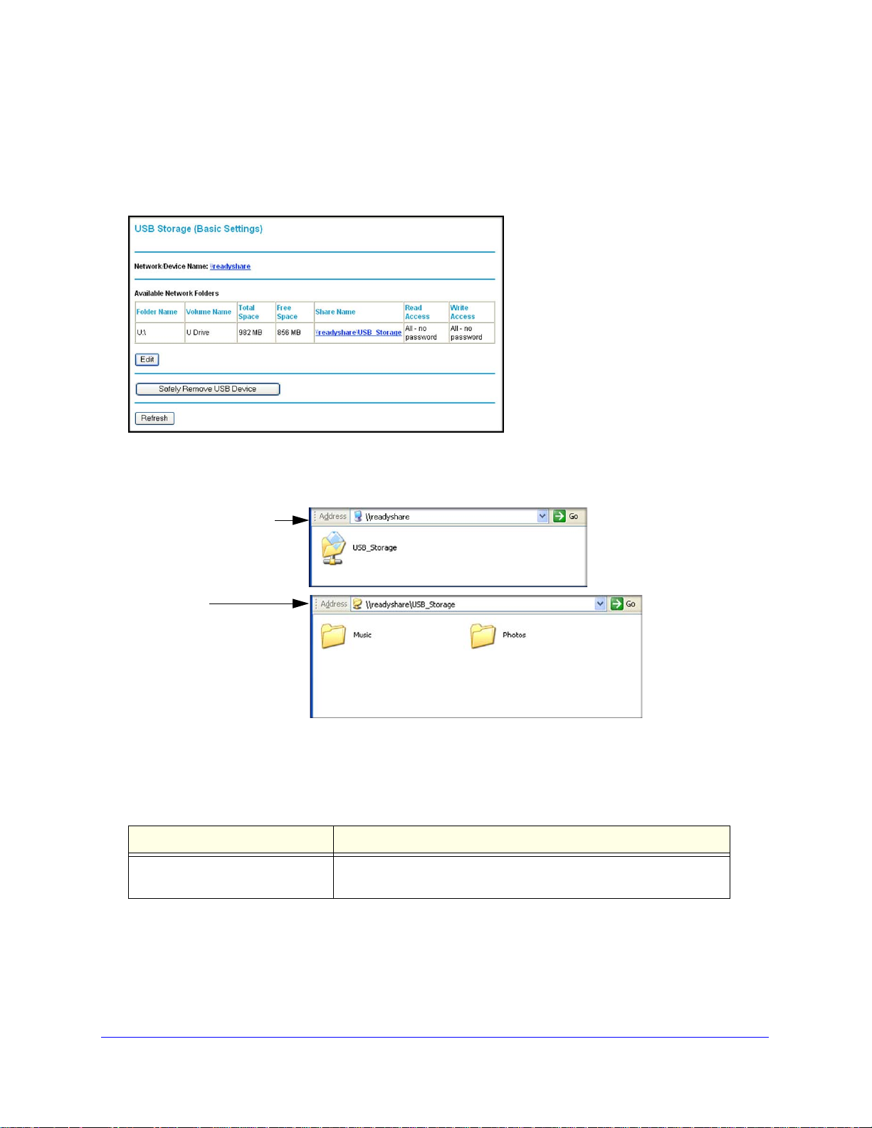
USB Storage Basic Settings
Y ou ca n view or edit basic settings for the USB storage device attach ed to your router. On the
router main menu under USB, select Basic Settings. The following screen displays:
By default, the USB storage device is available to all computers on your local area network
(LAN). To access your USB device from this screen, you can click the network or device
name or the share name.
You can also type \\readyshare in the address field of your web browser. If you logged in to
the router before you connected your USB device, you might not see your USB device in the
router screens until you log out and then log in again.
Table 8. USB Storage (Basic Settings)
Fields and buttons Description
Network Device Name The default is \\readyshare. This is the name used to access the
USB devic
e connected to the router.
USB Storage
44
Page 45
Mobile V oice HSP A+ Broadband 11n W ireless Router MVBR1210C
Table 8. USB Storage (Basic Settings) (continued)
Fields and buttons Description
Available
Network Folders
Edit button You can click the Edit b
Safely Remove USB Device
button
Folder Name Full path of the network folder.
Volume name Volume name from the storage device (either USB drive or HDD).
Total/Free
ce
Spa
Share Name • You can click the name shown, or you can type it in the address
Read and Write
ces
s
Ac
Shows the current utilization of the storage device.
field of your web browser.
• If Not Shared is shown, then the defa
and no other share for the root folder exists. Click the link to
change this setting.
Shows the network folder permissions and access controls.
• All-no password allows all users to access the network folder.
• admin u
main menu.
settings. See Edit a Network Folder on page 45.
Click to safely remove the USB device attached to your router. See
Unmount a USB Drive on pag
ses the same password that you use to log in to the router
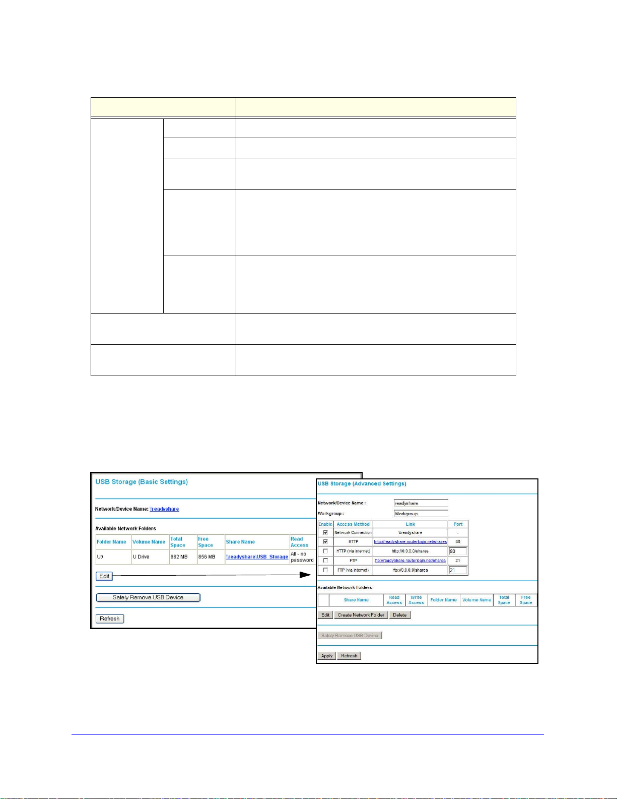
Edit a Network Folder
ult share has been deleted,
utton to edit the Available Network Folders
e 48.
This process is the same from either the USB Storage (Basic Settings) screen or the USB
Storage (Advanced Settings) screen. Click the Edit button to open the USB Storage
(Advanced Settings) screen:
You can use this screen to select a folder, to change the share name, or to change read
access or write access from All-no password to admin. The password for admin is the same
one that is used to log in to the router main menu. By default it is password.
USB Storage
45
Page 46

Mobile V oice HSP A+ Broadband 1 1n Wireless Router MVBR1210C
Note: You need to click Apply for your changes to take effect.
Configure USB Storage Advanced Settings
To configure advanced USB settings, from the router menu, under USB, select Advanced
Settings. The USB Storage (Advanced Settings) screen displays:
You can use this screen to specify access to the USB storage device. The following table
explains the fields and buttons in the USB Storage (Advanced Settings) screen.
Table 9. USB Storage (Advanced Settings)
Fields Description
Network Device Name The default is readyshare. This is the name used to access the USB device
connected to the router from your computer.
Workgroup If you are using a Windows workgroup rather than a domain, the workgroup
me is displayed here.
na
Access Method Network
ction
Conne
HTTP Disabled by default. If you enable this setting, you can type
HTTP (via
Internet)
FTP Disabled by default.
FTP (via
Internet)
Enabled by default, this allows all users on the LAN to have access to the
USB drive.
http://kbserver.netgear.com/produ
access the USB drive.
Di
sabled by default. If you enable this setting, remote users can type
http://kbserver.netgear.com/produ
access the USB drive over the Internet.
sabled by default. If you enable this setting, remote users can access the
Di
USB drive through FTP over the Internet.
cts/MVBR1210C-1BMCNS.asp to
cts/MVBR1210C-1BMCNS.asp to
USB Storage
46
Page 47

Mobile V oice HSP A+ Broadband 11n W ireless Router MVBR1210C
Table 9. USB Storage (Advanced Settings) (continued)
Fields Description
Available
Network Folders
Share Name • You can click the name shown, or you can type it into the ad dress field of
your web browser.
• If Not Shared is shown, then the default share h
other share for the root folder exists. Click the link to change this setting.
Read and Write
s
Acces
Folder Name Full path of the used by the network folder.
Volume name Volume name from the storage device (either USB drive or HDD).
Total/Free
a
ce
Sp
Shows the permissions and access controls on the network folder.
• All-no password allows all users to access the network folder.
• admin pro
the router main menu.
The current utilization of the storage device.
mpts you to enter the same password that you use to log in to
as been deleted, and no
Create a Network Folder
To create a network folder:
1. From the USB Storage (Advanced Settings) screen, click the Create Network Folder
utton to open the Create Network Folder screen:
b
2. Create a folder.
• You can specify the folder’s share name and change read access and w
All-no password to admin.
• The password for admin is th
e same one that is used to log in to the router main
menu. By default it is password.
3. Click Appl
y so that your changes take effect.
USB Storage
47
rite a c ce ss from
Page 48
Mobile V oice HSP A+ Broadband 1 1n Wireless Router MVBR1210C
WARNING:
Unmount a USB Drive
Unmount the USB drive first before physically unplugging it from
the router. If the USB disk is removed or a cable is pulled while
data is being written to the disk, it could result in file or disk
corruption.
To unmount a USB disk drive so that no users can access it, from the USB Settings screen,
click the Safely Remove USB button. This takes the drive offline.
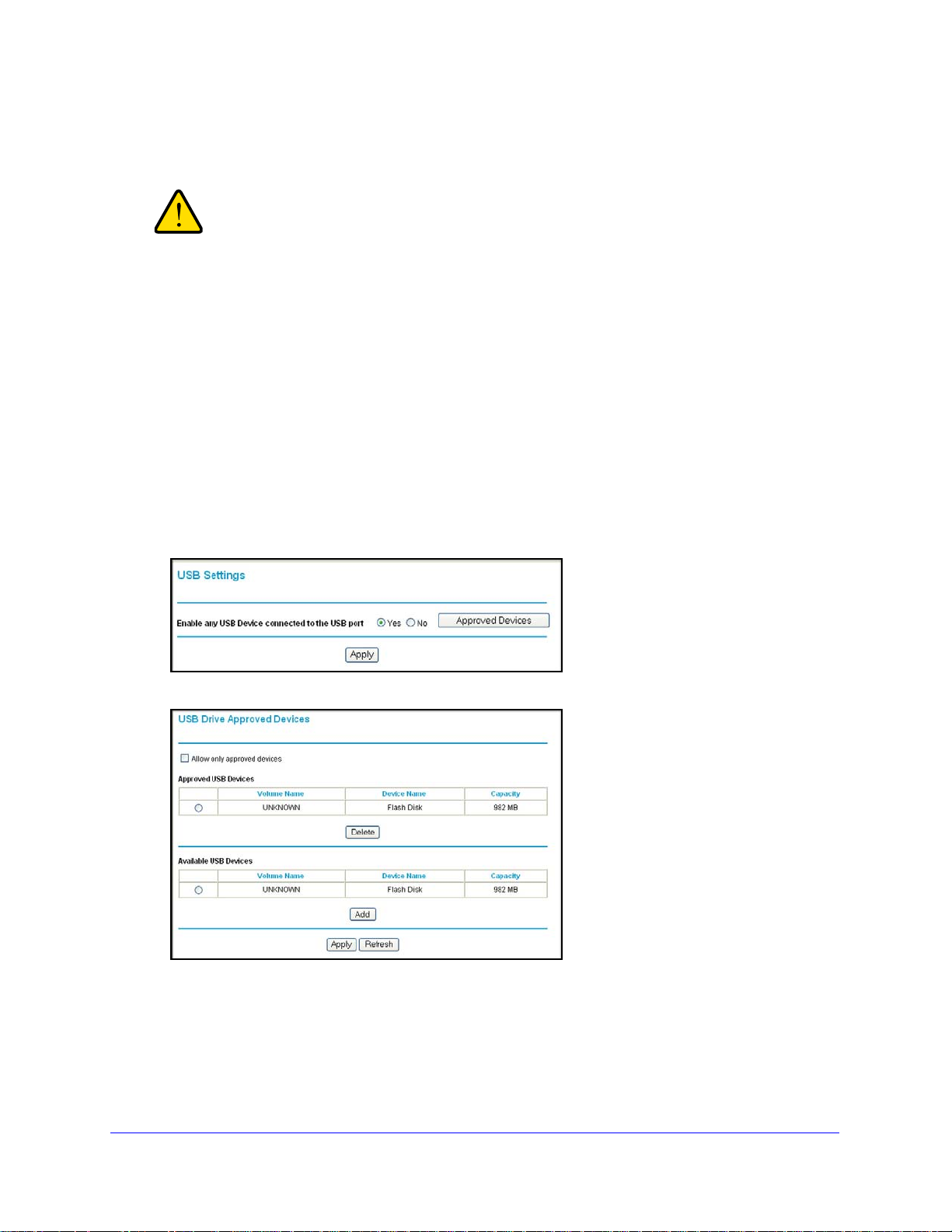
Specify Approved USB Devices
You can specify which USB devices are approved for use when connected to the router.
To specify approved USB devices:
1. On the router main menu, under Advanced, select USB Settings.
2. Click Approved Devices.
3. On the USB Drive Approved Devices screen, select the USB device from the Available USB
Devices list.
4. Click Add.
5. Select the Allow only
6. Click Apply so that
approved devices check box.
your change takes effect.
USB Storage
48
Page 49

Mobile V oice HSP A+ Broadband 11n W ireless Router MVBR1210C
If you want to approve another USB device, you need to first click the Safely Remove USB
Device button to unmount the currently connected USB device. Connect the other USB
device, and then repeat this process.
Connect to the USB Drive from a Remote Computer
To connect to the USB drive from remote computers using a web browser, you need to use
the router’s Internet port IP address.
Locate the Internet Port IP Address
To view the Internet port IP address:
1. L
og in to the router.
2. In the main menu, unde
3. Record
to connect to the router remotely.
the IP address that is listed for the Internet port. This is the IP address you can use
r Maintenance, select Router Status.
Access the Router’s USB Drive Remotely Using FTP
To connect to the router’s USB drive using a web browser:
1. Con
2. T
3. The directo
nect to the router by typing ftp:// and the Internet port IP address in the address field
of Internet Explorer or Netscape Navigator, for example, ftp://10.1.65.4. If you are using
Dynamic DNS, you can type the DNS name rather than the IP address.
ype the account name and password that provide access rights to the USB drive.
ries of the USB drive that your account has access to display, for example,
share/partition1/directory1. You can now read and copy files from the USB directory.
Connect to the USB Drive with Microsoft Network Settings
You can access the USB drive from local computers on your home or office network using
Microsoft network settings. You need to be running Microsoft Windows 2000, XP, or older
versions of Windows with Microsoft Networking enabled. You can use normal Explorer
operations such as dragging and dropping, opening files, or cutting and pasting files from:
• Microsof
• Win
• Network Neighbo
t Windows Start menu, Run option
dows Explorer
rhood or My Network Place
USB Storage
49
Page 50

Mobile V oice HSP A+ Broadband 1 1n Wireless Router MVBR1210C
Enable File and Printer Sharing
Each computer’s network properties need to be set to enable network communication with
the USB drive. File and Printer Sharing for Microsoft Networking needs to be enabled, as
described in the following sections.
Note: In Windows 2000 and Windows XP, File and Printer Sharing is
enabled by default.
Configure Windows 98SE and Windows ME
The easiest way to get to your network properties is to go to your desktop, right-click
Network Neighborhood, and then select Properties. File and Printer Sharing for Microsoft
Windows should be listed. If it is not, click Add, and follow the installation prompts.
Note: If you have any questions about File and Printer Sharing, contact
Microsoft for assistance.
Configure Windows 2000 and Windows XP
Right-click the network connection for your local area network. File and Printer Sharing for
Microsoft Windows should be listed. If it is not, click Install, and follow the installation
prompts.
USB Storage
50
Page 51
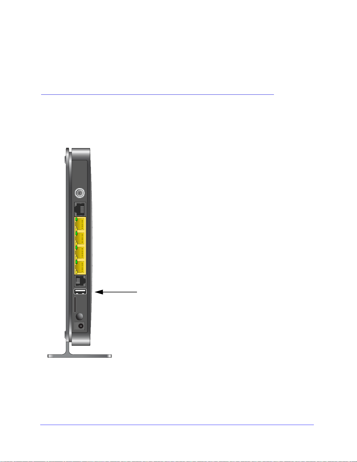
5. USB Printer
This chapter describes how to access and configure a USB printer attached to your router.
5
This chapter includes the following sections:
• USB Printer Control
51
Page 52

Mobile V oice HSP A+ Broadband 1 1n Wireless Router MVBR1210C
USB Printer Control
The USB Control Center utility allows you to control a shared USB device from your computer
that is connected to the USB port on your router. The utility allows you to control a printer.
wor
The utility has to be installed on each computer on your net
con trol the device. You can download this utility at
www.netgear.com/landing/en-us/readyshare.aspx.
k from which you want to
When you launch the USB Control Center utility, a screen similar
This is the main screen, which shows a device icon, the description for this USB device, and
its status.
Available. The d
evice is available
from the computer that you are using.
to the following displays:
Waiting to Connect. You
using. If this is the first time you are connecting, you might be prompted to install the device
driver.
The following menu selections are available:
• System. Exit the u
• Tools.
the following section, Control Center Configuration.
• About. V
Access the Control Center Configuration to set up your shared USB device. See
iew details about the USB Control Center software.
need to connect to this device from the computer that you are
tility.
USB Printer
52
Page 53

Mobile V oice HSP A+ Broadband 11n W ireless Router MVBR1210C
Control Center Configuration
Select Tools > Configuration to display the following screen:
Automatically execute when logging on Windows. Select this checkbox to have the utility
start automatically when you are logged in to Windows.
p
Timeout. S
Language. Select the display lan
ecify the time-out value for holding the USB resource when it is not in use.
guage for this utility.
USB Printer
The first time you use a printer, you need to click Connect. You might be asked to install the
driver for this printer. After the driver is installed, the printer status changes to Available.
Note: Some USB printers (for example: HP and Lexmark printer) request
that you do not connect the USB cable until you are prompted by the
installation software.
If the USB printer is detected and connected automatically, you need to disconnect the
printer, and then wait for the prompt asking you to click Connect.
USB Printer
53
Page 54

Mobile V oice HSP A+ Broadband 1 1n Wireless Router MVBR1210C
Once the printer shows Available status, the grayed out Paused state no longer displays in
the Windows Printers and Faxes window.
This USB printer is ready . Th e utility does not need to always hold the connection of this USB
printer. Once there is any print job for this printer, the USB utility connects to this USB printer
automatically, then prints. After the print job is done, the printer status returns to the Paused
state.
Scan with a Multifunction Printer
You can use the scan feature of a multifunction printer.
1. Make sure that th
2. Click the Network Scanner b
This activates the scanner window that is used to perform the scans.
e printer’s status shows as Available.
utton.
USB Printer
54
Page 55

6. Content Filtering
This chapter describes how to use the basic firewall features of the router to protect your
network.
• View, Select, and Save Logged Information
• Block Sites and Keywords
• Block Services
• Schedule Blocking
• Enable Security Event Email Notification
Note: For information about the advanced content filtering features port
forwarding and port triggering, see
Triggering on page 81.
Port Forwarding and Port
6
55
Page 56

Mobile V oice HSP A+ Broadband 1 1n Wireless Router MVBR1210C
View, Select, and Save Logged Information
The router logs security-related events such as denied incoming service requests, hacker
probes, and administrator logins. If you enabled content filtering in the Block Sites screen, the
Logs screen can show you when someone on your network tries to access a blocked site.
On the main menu, under Content Filtering, select Logs
Figure 4.
to display this screen:
Note: You can enable email notification to receive these logs in an email
message. See Enable Security Event Email Notification on page 62.
Log entries and action buttons are described in the following table.
Field or button Description
Current time The date and time the log entry was recorded.
Description or action The type of event and what action was taken, if any.
Source IP The IP address of the initiating device for this log entry.
Source port and interface The service port number of the initiating device, and whether it
nated
origi
Destination The name or IP address of the destination device or website.
Destination port and interface The service port number of the destination device, and whether it is
on the LAN or WA
Refresh button Refresh the log screen.
Clear Log button Clear the log entries.
from the LAN or WAN.
N.
Content Filtering
56
Page 57

Mobile V oice HSP A+ Broadband 11n W ireless Router MVBR1210C
Field or button Description
Send Log button Email the log immediately.
Apply button Apply the current settings.
Cancel button
Clear the current settings.
Log Message Examples
Following are examples of log messages. In all cases, the log entry shows the time stamp as
Day, Year-Month-Date Hour:Minute:Second.
Activation and Administration
This entry indicates a power-up or reboot with initial time entry:
Tue, 2002-05-21 18:48:39 - NETGEAR activated
This entry shows an administrator logging in to and out from IP address 192.168.0.2:
Tue, 2002-05-21 18:55:00 - Administrator login successful - IP:192.168.0.2
Thu, 2002-05-21 18:56:58 - Administrator logout - IP:192.168.0.2
This entry shows a time-out of the administrator login:
Tue, 2002-05-21 19:00:06 - Login screen timed out - IP:192.168.0.2
This entry shows when the log was emailed:
Wed, 2002-05-22 22:00:19 - Log emailed
Dropped Packets
These entries show an inbound FTP (port 21) packet, User Dat agram Protocol (UDP) p acket
(port 6970), and Internet Control Message Protocol (ICMP) packet (port 0) being dropped as
a result of the default inbound rule, which states that all inbound packets are denied:
Wed, 2002-05-22 07:15:15 - TCP packet dropped - Source:64.12.47.28,4787 ,WAN
- Destination:134.177.0.11,21,LAN - [Inbound Default rule match]
Sun, 2002-05-22 12:50:33 - UDP packet dropped - Source:64.12.47.28,10714,WAN
Destination:134.177.0.11,6970,LAN - [Inbound Default rule match]
Sun, 2002-05-22 21:02:53 - ICMP packet dropped - Source:64.12.47.28,0,WAN -
estination:134.177.0.11,0,LAN - [Inbound Default rule match]
D
Block Sites and Keywords
The router provides a variety of options for blocking Internet-based content and
communications services. With its content filtering feature, the router prevents objectionable
content from reaching your computers. You can control access to Internet content by
screening for keywords within web addresses. Content filtering options include:
Content Filtering
57
Page 58

Mobile V oice HSP A+ Broadband 1 1n Wireless Router MVBR1210C
• Keyword blocking of HTTP traffic.
• Outbound service blocking. Limits acce
ss from your LAN to Internet locations or services
that you specify as off-limits.
• Denial of
service (DoS) protection. Detects and thwarts DoS attacks such as Ping of
Death, SYN flood, LAND attack, and IP spoofing.
• Blocking unwanted traffic from the Internet to your LAN.
The
router allows you to restrict access to Internet content
address keywords.
To block sites and keywords:
based on web addresses and web
1. Log in to the router as describe
2. On the main menu, select Block Sites to display the
d in Log In to Your Router on page 12.
Block Sites screen:
Never is selected by default.
3. To enable keyword blocking, select one of the following:
• Per Schedule. T
urn on keyword blocking according to the settings on the Schedule
screen.
• Always. Turn
on keyword blocking all the time, independent of the setting in the
Schedule screen.
4. Enter a keywo
d or domain in the Keyword field, click Add Keyword, and then click Apply.
r
Some examples of keyword applications are shown in the following chart.
Keyword Result
XXX Block the URL http://www.badstuf.com/xxx.html.
.com Only websites with other domain suffixes (such as .edu or .gov) can be viewed.
. ( a period) Block all Internet browsing access.
Content Filtering
58
Page 59

Mobile V oice HSP A+ Broadband 11n W ireless Router MVBR1210C
Up to 32 entries are supported in the Keyword list.
Note: If you block sites, you can set up the router to log a ttempts to access
them. See View, Select, and Save Logged Information on page 56.
o delete a keyword or domain, select it from the list, click Delete Keyword, and then click
5. T
Apply .
o specify a trusted user, enter that computer’s IP address in the Trusted IP Address field,
6. T
and then click Apply .
You can specify one trusted user, which is a compu
ter that will be exempt from blocking
and logging. Since the trusted user will be identified by an IP address, you should
configure that computer with a fixed IP address.
7. Click App
ly to save your settings.
Content Filtering
59
Page 60
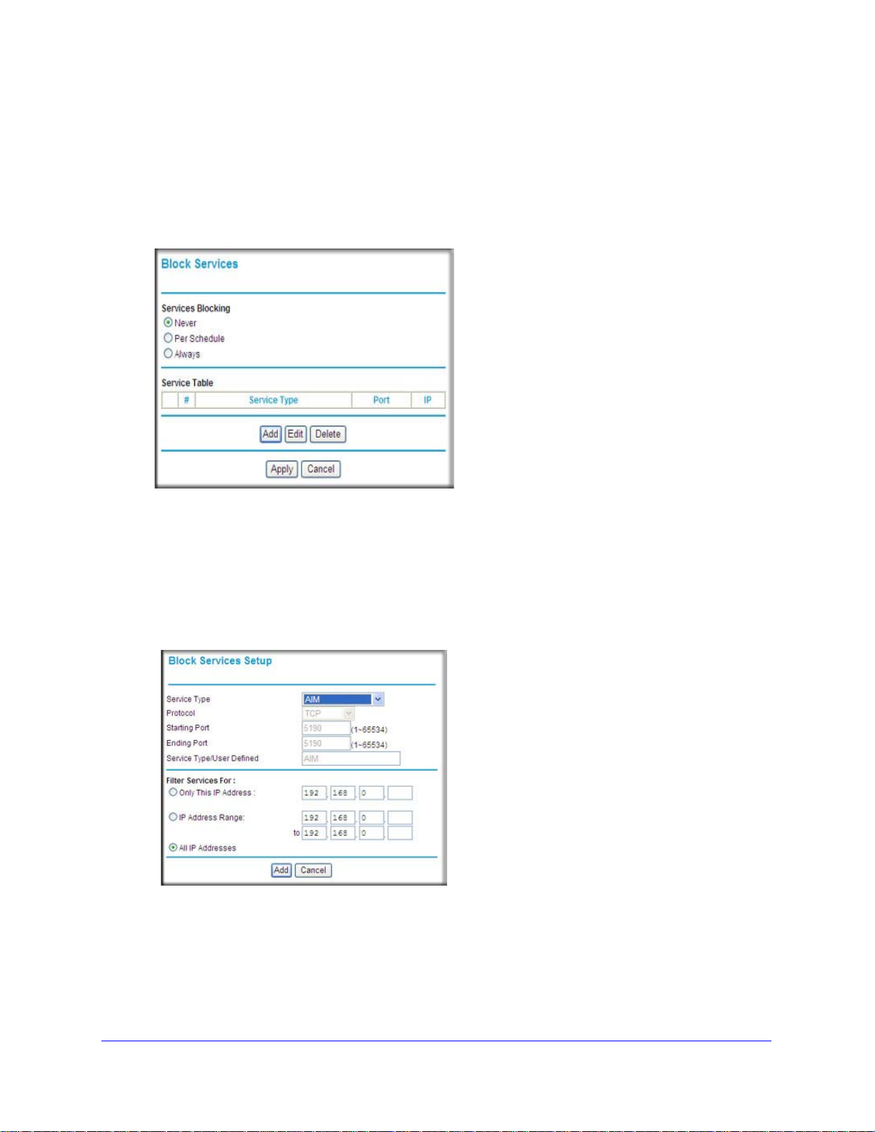
Mobile V oice HSP A+ Broadband 1 1n Wireless Router MVBR1210C
Block Services
To block services:
1. Log in to the router as describe
2. In the main menu, under Content Filtering, select Blo
Never is selected by default.
3. Select one of the fo llowing:
• Per Schedule. T
screen.
• Always. Turn
urn on keyword blocking according to the settings in the Schedule
on keyword blocking all the time, independent of the Schedule screen.
d in Log In to Your Router on page 12.
ck Services to display this screen:
4. Click Add, and
5. Either select a service from the Service Type drop-down list, or use the Service/Type User
Defined field to create a custom service.
6. Click Add and the service is listed in the Service T
7. Click Apply to save your settings.
the following screen displays:
able on the Block Services screen.
Content Filtering
60
Page 61
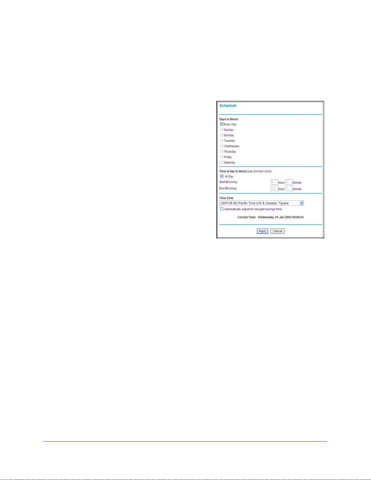
Mobile V oice HSP A+ Broadband 11n W ireless Router MVBR1210C
Schedule Blocking
The router uses Network Time Protocol (NTP) to obtain the current time and date from one of
several network time servers on the Internet.
Set Your Time Zone
To localize the time for your log entries, you need
to specify your time zone.
To set the time zone:
1. Log in to the router as described in Log In to
Your Router on pag
2. On the main menu under Content Filtering,
se
lect Schedule:
3. Select your time zone. This setting will be used
for the
time zone and for time-stamping log entries.
If your time zone is currently in daylight savings
time
daylight savings time check box.
4. Click Appl
blocking schedule according to your local
, select the Automatically adjust for
y to save your settings.
e 12.
Schedule Firewall Services
If you enabled service blocking in the Block Services screen or port forwarding in the Port
Forwarding/Port Triggering screen, you can set up a schedule for when blocking occurs or
when access is not restricted.
To schedule firewall services:
1. Log in to the router as described in Log In to
2. On the main menu, select Schedule.
3. To block Internet services base d on a schedule, select Every Day, or select one
days. If you want to limit access completely for the selected days, select All Day. Otherwise,
to limit access during certain times for the selected days, fill in the Start Blocking and End
Blocking fields.
The Schedule screen displays.
Your Router on page 12.
or more
4. Enter the values in 24-hour time format. For example, 10:30 a.m. would be 10 hours and 30
utes, and 10:30 p.m. would be 22 hours and 30 minutes. If you set the start time after the
min
end time, the schedule will be effective through midnight the next day.
5. Click Appl
y to save your changes.
Content Filtering
61
Page 62

Mobile V oice HSP A+ Broadband 1 1n Wireless Router MVBR1210C
Enable Security Event Email Notification
To set up the router so that you can receive
logs and alerts by email, select Email from the
router menu to display the following screen:
To receive alerts and logs by email:
1. Select the Tu
check box.
2. Fill in the fields to send
through email.
• Y our Outgoing Mail Server. Enter
name or IP address of the outgoing
SMTP mail server of your ISP (such as
mail.myISP.com).
• Send to This Email Address. En
the email address where you want to
send the alerts and logs. Use a full
email address, such as ChrisXY@myISP.com.
• My mail server requires
to your SMTP server to send email. If you select this feature, you need to enter the
user name and password for the mail server.
Tip: If you cannot remember this information, check the
3. Specify when you want the alerts and logs to be sent :
• Send alert imme
notification of a significant security event, such as a known attack, port scan, or
attempted access to a blocked site.
rn E-mail Notification On
alerts and logs
the
ter
authentication. Select this check box if you need to log in
program.
diately. Select this check box if you would like immediate
settings in your email
• Send logs according to this schedule. S
Hourly, Daily, Weekly, or When Full.
• Day for sending
the log is sent weekly.
• Time for sending log. S
log is sent daily or weekly.
If the Weekly, Da
period, the log is automatically emailed to the specified email address. After the log is
sent, it is cleared from the router’s memory. If the router cannot email the log file, the log
buffer might fill up. In this case, the router overwrites the log and discards its contents.
4. Click Apply so that
log. Specifies which day of the week to send the log. Relevant when
pecifies the time of day to send the log. Relevant when the
ily, or Hourly option is selected and the log fills up before the specified
your changes take effect.
Content Filtering
62
pecifies how often to send the logs:
Page 63

7. Managing Your Network
This chapter describes how to perform network management tasks with your Mobile Voice
HSPA+ Broadband 11n Wireless Router.
• Router Status
• View Attached Devices
• Back Up, Restore, or Erase Your Settings
• Protect Access to Your Router
• Run Diagnostic Utilities and Reboot the Router
• Upgrade the Router Firmware
• Upgrade the Module Firmware
7
63
Page 64

Mobile V oice HSP A+ Broadband 1 1n Wireless Router MVBR1210C
Router Status
You can use the Router S t atus screen to view the st atus of the router, to show statistics, or to
view the connection status.
To view the router status:
1. From the main me
nu, under Maintenance, select Router Status to view this screen.
You can use the Router Status screen to check the current settings a nd st a tistics for yo ur
router. This screen shows you the current settings. If something needs to be changed,
you will have to change it on the relevant screen.
• Active Connection. This is the curren
• Router Inform
- Account Name. This is the current hardware the router is using.
- Firmware Version. This is the current software the rout
change if you upgrade your router.
• Ethernet Po
Broadband Account Settings screens.
ation
rt. These are the current settings that you set in the Setup Wizard or
Managing Y our Network
t WAN interface the router is using.
er is using. This will
64
Page 65

Mobile V oice HSP A+ Broadband 11n W ireless Router MVBR1210C
- MAC Address. The physical address of the Router, as seen from the Ethernet
WAN.
- IP Add
ress. Current Internet IP address. If assigned dynamically , and no Internet
connection exists, this will be blank or 0.0.0.0
- Networ
k Type. Type of network client.
- IP Subnet
- Ga
teway IP Address. Gateway IP address of the Router.
- Domain Na
ireless Broadband Modem. These are the current settings of mobile broadband
• W
Mask. The subnet mask associated with the Internet IP address
me Server. Displays the address of the current DNS.
device.
- Modem Identity. Identity o
- Mo
- Mo
- IMSI.
- IMEI.
- Op
- Netwo
- Netwo
• W
dem SW version. Software/Firmware version of this USB modem device.
dem driver version. Kernel driver version.
International Mobile Subscriber Identity.
International Mobile station Equipment Identity.
erator. The internet service provider name which has connected.
rk mode. Current access technology
rk band. Current access technology
ireless Broadband Port. These are the current settings of mobile broadband
f this USB modem device.
WAN.
- Connecti
on Status. The current state of the Mobile broadband connection to
your cellular ISP.
- IP Address.
- Protocol. Prot
- IP Subnet
Mobile broadband IP address of the Router.
ocol of the mobile broadband port.
Mask. Subnet mask associated with the mobile broadband IP address.
- Domain Na
• LAN P
ort. These are the current settings, as set in the LAN IP Setup page.
- MAC Address.
- IP Address.
- DHC
P. Indicates if the Router is acting as a DHCP Server for devices on your
me Server. Displays the address of the current DNS.
The physical address of the Router, as seen from the local LAN.
LAN IP address of the Router.
LAN.
- IP Subnet
• W
ireless Port. These are the current settings, as set in the Wireless Settings page.
- Name (SSID). SSID of th
- Region.
- Channel. The current
ireless AP. Indicates if the Access Point feature of the Router is enabled or not.
- W
Mask. Subnet mask associated with the LAN IP address.
e Router.
The location (country).
channel in use.
If not enabled, the Wireless LED on the front panel will be off.
- Bro
adcast Name. Indicates if the Router is broadcasting its SSID.
Managing Y our Network
65
Page 66
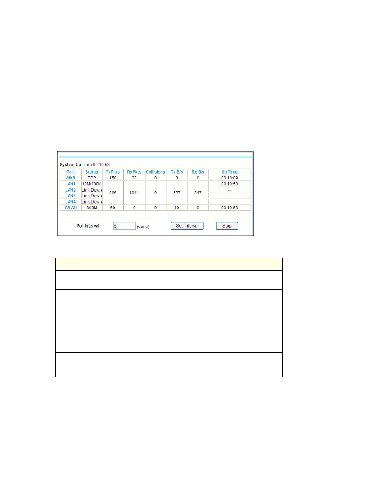
Mobile V oice HSP A+ Broadband 1 1n Wireless Router MVBR1210C
2. Click Show Statistics to see router performance statistics such as the number of packets
sent and number of packets received for each port.
See Showing Statistics on pag
3. Click Connection
Status to see information about your current connection.
For information about the Internet connection, see Connection Status on p
e 66 for information about statistics.
age 67.
Showing Statistics
Click the Show Statistics button on the Router Status screen to display router usage
statistics:
The following table explains the statistic fields.
Field Description
Status The link status. Note that LAN2, LAN3, and LAN4 are guest
networks.
TxPkts The number of packets transmitted on this port since rese
clear.
RxPkts The number of packets received on this port since reset or manual
clear.
llisions The number of collisions on this port since reset or manual clear.
Co
Tx B/s The average egress line utilization for this port.
Rx B/s The average ingress line utilization for this port.
Up Time The time elapsed since the last power cycle or reset.
t or manual
Managing Y our Network
66
Page 67

Mobile V oice HSP A+ Broadband 11n W ireless Router MVBR1210C
Connection Status
Click the Connection Status button on the Router Status screen:
This screen shows the following statistics:
Field Description
Mobile Broadband
Status
Connection Status The status of the Internet connection.
• Scanning. The mo
networks in your area.
• Connected. The router is connected to
• No USB Device Attached. The router does not detect a
USB modem connected to its USB port. Either the modem is
disconnected, or it is not correctly seated. To correct the
problem, remove the modem and reinsert it into the port.
Received Signal Quality
n dBm
(i
Bytes Transmitted The number of bytes transmitted in the most recent connection
Bytes Received The number of bytes received in the most recent connection
Tx B/s The transmission rate.
Rx B/s The receiving rate.
System Uptime Time elapsed since the last reboot.
)
Modem radio reception. A small, negative number indicates
good signal quality.
session.
session.
dem is scanning for broadband wireless
the Internet.
Managing Y our Network
67
Page 68

Mobile V oice HSP A+ Broadband 1 1n Wireless Router MVBR1210C
Field Description
Connection Status Connection Time The time elapsed since the last connection to the Internet
through the broadband port.
Connecting to Server The connection status.
Negotiation Success or Failed.
Authentication Success or Failed.
Getting IP Address The IP address assigned to the WAN port by the ADSL
rnet se
Inte
rvice provider.
Getting Network Mask
The network mask assigned to the WAN port by the ADSL
Internet service provider.
View Attached Devices
The Attached Devices screen shows all IP devices that the router discovered on the local
network. From the main menu, under Maintenance, select Attached Devices:
For each device, the table shows the IP address, device name if available, and the Ethernet
MAC address. If the router is rebooted, this data is lost until the router rediscovers the
devices. To force the router to look for attached devices, click the Refresh button.
Managing Y our Network
68
Page 69

Mobile V oice HSP A+ Broadband 11n W ireless Router MVBR1210C
Back Up, Restore, or Erase Your Settings
The configuration settings of the router are stored in a configuration file in the router. This file
can be backed up to your computer, restored, or reverted to factory default settings. The
procedures in the following sections explain how to do these tasks.
Back Up the Configuration to a File
To back up the configuration:
1. Log in to the router. Type http://www.routerlogin.net in the address field of your
nternet browser. Enter admin for the user name and your password (or the default,
I
password
).
2. Under Maintenance on the main menu, se lect Backu
Settings screen.
3. Click Save to save a copy of the current settings.
4. Store the .cfg file on a computer on your network.
p Settings to display the Backup
Restore the Configuration from a File
To restore the configuration:
1. Log in to the router. Type http://www.routerlogin.net in the address field of your
nternet browser. Enter admin for the user name and your password (or the default,
I
password
).
2. Under Maintenance on the main menu, se lect Backu
3. Enter the full path to the file on your network, or click Br
4. When you have located the
The router reboots.
.cfg file, click Restore to upload the file to the router.
Managing Y our Network
69
p Settings.
owse to locate the file.
Page 70

Mobile V oice HSP A+ Broadband 1 1n Wireless Router MVBR1210C
Erase the Configuration
Y ou can use the Erase feature to erase the configu ration settings and restore the router to the
factory default settings.
To erase the configuration:
1. Under Mainte
2. Click Erase.
The router reboots.
After an erase, the router password is p
the router DHCP client is enabled.
Note: To restore the factory default settings when you do not know the
nance on the main menu, select Backup Settings.
assword, the LAN IP address is 192.168.0.1, and
login password or IP address, press the Restore Factory Settings
button on the bottom of the router for 6 seconds.
Protect Access to Your Router
For security reasons, the router has its own user name and password. Also, after a period of
inactivity, the router automatically logs itself out. The user name and password are not the
same as a user name or password you might use to log in to your Internet connection.
NETGEAR recommends that you change this password to a
ideal password should contain no dictionary words from any language, and should be a
mixture of both uppercase and lowercase letters, numbers, and symbols. Your password can
be up to 30 characters.
more secure password. The
Change the Built-In Password
To change the password:
o log in to the router, type http://www.routerlogin.net in the address field of your
1. T
Internet browser. Enter admin for the user name and your password (or the default,
password
Note: If you changed the password and do not remember what it is, you
).
can reset the router to its factory default settings. See
Default Configuration and Password on page 106.
Managing Y our Network
Restore the
70
Page 71

Mobile V oice HSP A+ Broadband 11n W ireless Router MVBR1210C
2. From the main menu, under Maintenance, select Set Password.
3. To change the password, first enter the old password, and then enter the new password
twice.
4. Click Appl
Note: After changing the password, you need to log in again to continue
y to save your changes.
the configuration. If you have backed up the router settings
previously, you should do a new backup so that the saved settings
file includes the new password.
Change the Administrator Login Time-Out
For security, the administrator login to the router configuration times out after a period of
inactivity.
To change the time-out:
1. In the Set Password screen, type a number in the Administrator login times out field.
he suggested default value is 5 minutes.
T
2. Click Appl
y to save your changes, or click Cancel to keep the current period.
Run Diagnostic Utilities and Reboot the Router
The router has a diagnostics feature. You can use the Diagnostics screen to perform the
following functions from the router:
• Ping
• Perform a DNS lookup
• Display the routing table to identify what other routers the router is communicating with.
an IP address to test connectivity to see if you can rea
is enabled, the ping packet always goes through the VPN if the VPN tunnel is enabled
and working.
to test if an Internet name resolves to an IP address to verify that
the DNS server configuration is working.
ch a remote host. If Ping VPN
•
Reboot the router to enable new network configurations to t
with the router’s network connection.
Managing Y our Network
71
ake effect or to clear problems
Page 72

Mobile V oice HSP A+ Broadband 1 1n Wireless Router MVBR1210C
From the main menu, under Maintenance,
select Diagnostics. Click the following
buttons to perform the diagnostic tests.
• Ping. Type an IP address.
• Lookup. A Domain Name Server (DNS
converts the Internet name such as
www.n etgear .com to an IP address. If you
need the IP address of a server on the
Internet, you can do a DNS lookup to find
the IP address.
)
• Display.
Typically, this information is used only by
technical support.
• Reboo
If you reboot the router , you will lose your
connect
rebooting.
• Save. Save the diagnostic inf
• Open. Vi
View the internal routing table.
ut down and restart the router .
t. Sh
ion. To access the router you will need to log in again after it has finished
ormation.
ew the module data.
Upgrade the Router Firmware
Note: This section deals with upgrading the router firmware. For
information about upgrading the mobile broadband modem
firmware, see Upgrade the Module Firmware on page 73.
The router firmware is stored in flash memory and can be u
released by NETGEAR. Upgrade files can be downloaded from the NETGEAR website. If the
upgrade file is compressed (a .zip file), you need to first extract the binary (.bin or .img) file
before uploading it to the router.
pgraded as new firmware is
NETGEAR recommends that you back up your configur
upgrade. After the upgrade is complete, you might need to restore your configuration
settings.
To upgrade the router firmware:
1. Download and unzip th
The web browser used to upload new router firmware into the router needs to support
HTTP uploads. NETG
Mozilla Firefox 2.0 or later.
e new router firmware file from NETGEAR.
EAR recommends using Microsoft Internet Explorer 5.0 or later, or
Managing Y our Network
72
ation before doing a router firmware
Page 73

Mobile V oice HSP A+ Broadband 11n W ireless Router MVBR1210C
WARNING:
2. Log in to the router. Type http://www .routerlogin.net in the address field of your Internet
browser. Enter admin for the user name and your password (or the default, password
).
3. From the main menu, under Maintenan
4. Click Browse to locate the bina ry (.bin or .img) upgrade file.
5. Click Upload
.
When uploading firmware to the router, do not interrupt the web
browser by closing the window, clicking a link, or loading a new
page. If the browser is interrupted, it might corrupt the firmware,
causing router to be unworkable and inaccessible. When the
upload is complete, your router will automatically restart. The
upgrade process typically takes about 1 minute. In some cases,
you might need to clear the configuration and reconfigure the
router after upgrading.
ce, select Router Upgrade to display this screen.
Upgrade the Module Firmware
Note: This section deals with upgrading the mobile broadband modem
firmware. For information about upgrading the router firmware, see
Upgrade the Router Firmware on page 72.
The module firmware is stored in flash memory and can b
firmware is released by NETGEAR or the module vendor. Upgrade files can be downloaded
from the NETGEAR or module vendor website. If the upgrade file is compressed (a .zip or
.exe file), you need to first extract the binary (.cwe) file before uploading it to the router.
NETGEAR recommends that you back up your configura
upgrade. After the upgrade is complete, you might need to restore your configuration
settings.
To upgrade the module firmware:
1. Download and unzip the n
vendor.
ew module firmware file from NETGEAR or the module
e upgraded as new module
tion before doing a module firmware
Managing Y our Network
73
Page 74

Mobile V oice HSP A+ Broadband 1 1n Wireless Router MVBR1210C
WARNING:
The web browser used to upload new module firmware into the router needs to support
HTTP uploads. NETGEAR recommends using Microsoft Internet Explorer 5.0 or later, or
Mozilla Firefox 2.0 or later.
2. Log in to the router. Type http://
www.routerlogin.net in the address field of your Internet
browser. Enter admin for the user name and your password (or the default, password
3. From the main menu, under Maintenance, select Module Upgrade to display this
4. Click Browse to locate the binary (.cwe) upgrade file.
5. Click Upload.
When uploading module firmware to the router, do not interrupt
the web browser by closing the window, clicking a link, or loading
a new page. If the browser is interrupted, it might corrupt the
firmware, causing router to be unworkable and inaccessible.
When the upload is complete, your router will automatically
restart. The upgrade process typically takes about 1 minute. In
some cases, you might need to clear the configuration and
reconfigure the router after upgrading.
).
screen.
Managing Y our Network
74
Page 75

8. Advanced
This chapter describes how to configure the advanced features of your Mobile Voice HSPA+
Broadband 11n Wireless Router.
• SIM Settings
• Advanced Wireless Settings
• Wireless Repeating Function
• Port Forwarding and Port Triggering
• WAN Setup
• LAN Setup
• QoS Setup
• Dynamic DNS
• Use Static Routes
• Enable Remote Management
• Universal Plug and Play
• Traffic Meter
8
75
Page 76
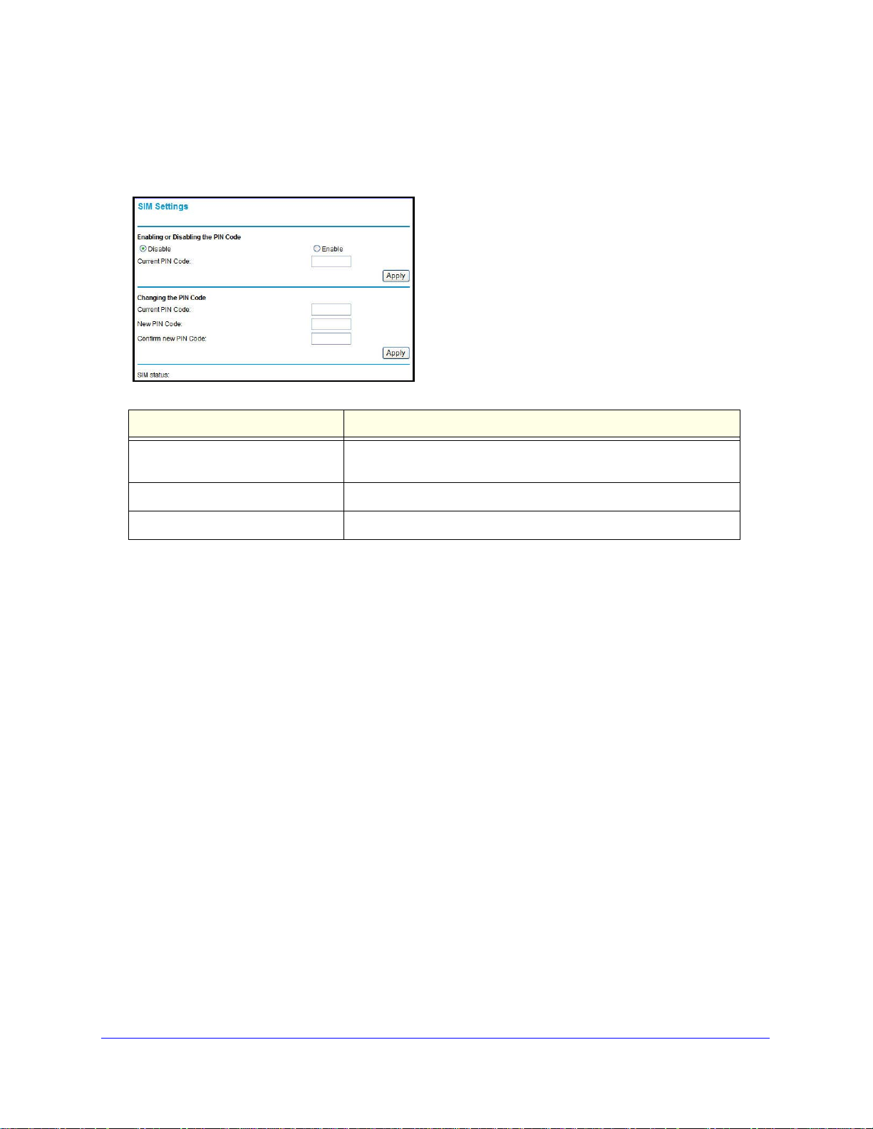
Mobile V oice HSP A+ Broadband 1 1n Wireless Router MVBR1210C
SIM Settings
From the main menu, select SIM Settings to display the following screen:
Field Description
Enabling or Disabling the PIN Code Controls whether the PIN code on the SIM card will be used to
connect to th
Changing the PIN Code Changes the PIN code on the SIM card.
SIM status Current SIM card access status.
e network.
Advanced
76
Page 77
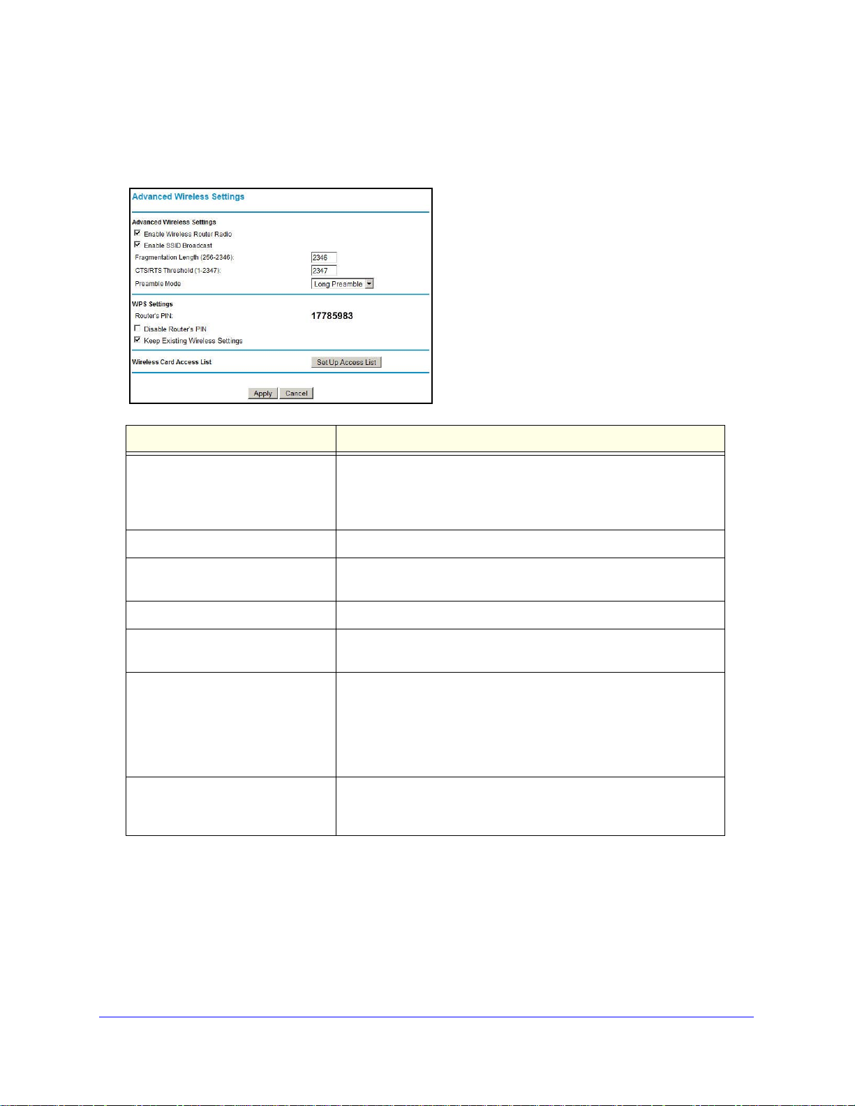
Mobile V oice HSP A+ Broadband 11n W ireless Router MVBR1210C
Advanced Wireless Settings
From the main menu, select Advanced Wireless Settings to display the following screen:
Field Description
Enable Wireless Router Radio Selected by default, this setting enables the wireless radio, which
allows the router to work as a wireless access point.
Turning off the wireless radio can be helpful for configuration,
ork tuning, or troubleshooting.
netw
Enable SSID Broadcast The router broadcasts its wireless network na
Fragmentation Length, CTS/RTS
Threshold, and Preamble Mode
Router’s PIN The PIN number used for Push 'N' Connect.
Disable Router’s PIN By default, this check box is cleared. This
Keep Existing Wireless Settings By default, this check box is cleared. This
Set Up Access List Access control is disabled by defau
These should be left at their default settings.
discover the router’s PIN.
automatically generate the SSID and WPA/WPA2 security settings
when it implements WPS. After WPS is implemented, the router
automatically selects the Keep Existing Wireless Settings check box
so that your SSID and wireless security settings remain the same if
other WPS-enabled devices are added later.
lt
so that any computer
configured with the correct SSID can connect. See Restrict Access
by MAC Address on pag
e 78.
me (SSID).
allows the WPS clients to
allows the router to
Wireless Station Access Control
By default, any wireless computer configured with the correct SSID and wireless security
settings is allowed access to your wireless network. You can use wireless access point
settings in the Wireless Settings screen to further restrict wireless access to your network:
Advanced
77
Page 78

Mobile V oice HSP A+ Broadband 1 1n Wireless Router MVBR1210C
• Turn off wireless connectivity completely.
Y ou can completely turn of f the wireless portion
notebook computer to wirelessly connect to your router, and you take a business t rip, you
can turn off the wireless portion of the router while you are traveling. Other members of
your household who use computers connected to the router through Ethernet cables can
still use the router. To do this, clear the Enable Wireless Router Radio check box on the
Advanced Wireless Settings screen, and then click Apply.
• Hide
your wireless network name (SSID).
By default, the router is set to broadcast its wireless network name (SSID). You can
rict wireless access to your network by not broadcasting the wireless network name
rest
(SSID). To do this, clear the Enable SSID Broadcast check box on the Advanced
Wireless Settings screen, and then click Apply. Wireless devices will not “see” your
router. You need to configure your wireless devices to match the wireless network name
(SSID) of the router.
Note: The SSID of any wireless access adapters needs to match the SSID
you configure in the router. If they do not match, you will not get a
wireless connection to the router.
of the router. For example, if you use your
Restrict Access by MAC Address
For increased security, you can restrict access to the wireless network to allow only specific
computers based on their MAC addresses. You can restrict access to only trusted computers
so that unknown computers cannot wirelessly connect to the Mobile Voice HSPA+
Broadband 11n Wireless Router. MAC address filtering adds an obstacle against unwanted
access to your network, but the data broadcast over the wireless link is fully exposed.
Note: If you configure the router from a wireless computer, add your
computer’s MAC address to the access list. Otherwise you will lose
your wireless connection when you click Apply. You need to then
access the router from a wired computer, or from a wireless
computer that is on the access control list, to make any further
changes.
Advanced
78
Page 79

Mobile V oice HSP A+ Broadband 11n W ireless Router MVBR1210C
To restrict access based on MAC addresses:
1. From the main menu, under Advanced, select Wireless Settings. Click Set Up Access
List to display the Wireless Card Access List screen.
2. Adjust the list as needed for your network. You can add devices to the Trusted Wireless
Stations list. Click Add to display the following screen:
3. You can add devices to the list using either of the following methods:
• If the computer is in the Available Wireless Cards table, select its radio button to
captu
re its MAC address.
• Use the Wireless Card Entry fields to enter the MAC address of the device to be
a
dded. The MAC address can usually be found on the bottom of the wireless device.
• If no device name displays when you enter the MAC address, you can type a
d
escriptive name for the computer that you are adding.
4. Click Appl
y to save
these settings. Now, only devices on this list will be allowed to wirelessly
connect to the router.
Advanced
79
Page 80
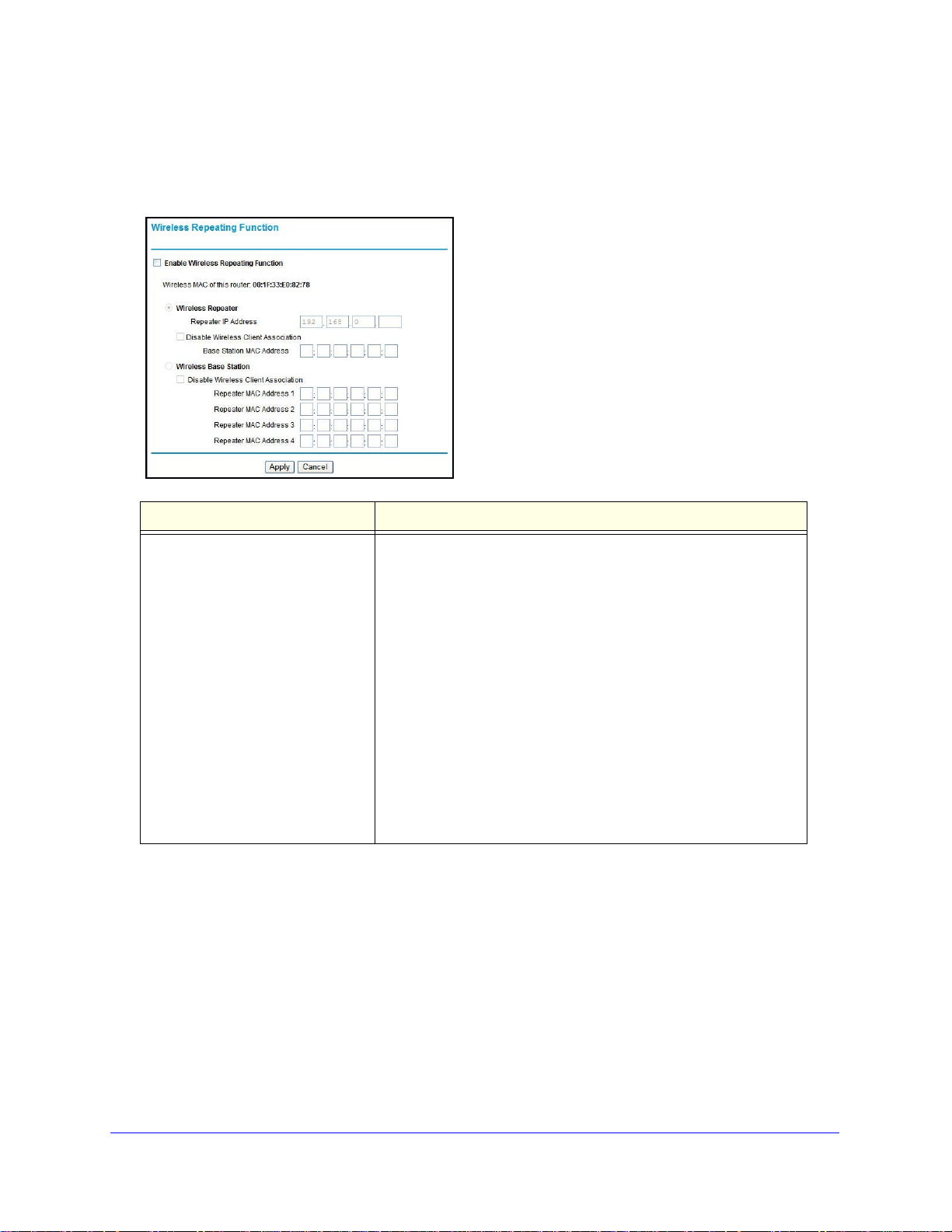
Mobile V oice HSP A+ Broadband 1 1n Wireless Router MVBR1210C
Wireless Repeating Function
From the main menu, select Wireless Repeating Function to display the following screen:
Field Description
Enable Wireless Repeating Function Enable this if you wish to use either b
and then select the mode you want for your environment.
• Wireless Repeater.
communicate only with another Base Station–mode wireless
station. You need to enter the MAC address (physical address) of
the other base station–mode wireless station in the field provided.
WEP / WPA-PSK [TKIP] can (and should) be used to protect this
communication.
ireless Base Station. Sele
• W
"master" for a group of repeater-mode wireless stations. The other
repeater-mode wireless stations need to be set to wireless
repeater-mode, using this MVBR1210C's MAC address. They then
send all traffic to this master, rather than communicating directly
with each other. WEP / WPA-PSK [TKIP] can (and should) be used
to protect this traffic. If this option is selected, you need to enter
the MAC addresses of the other access points in the fields
provided.
In this mode, the MVBR1210C will
ct this only if this MVBR1210C is the
ridge mode or repeater mode,
Advanced
80
Page 81

Mobile V oice HSP A+ Broadband 11n W ireless Router MVBR1210C
Port Forwarding and Port Triggering
Port forwarding and port triggering are advanced features that affect the behavior of the
firewall in your router. In the Port Forwarding / Port Triggering screen, you can make local
computers or servers available to the Internet for different services (for example, FTP or
HTTP), to play Internet games (like Quake III), or to use Internet applications (like
CU-SeeMe).
i
• Port forward
port forwarding is set up, requests from the Internet are forwarded to the correct server.
• Port triggering monitors outb
outbound port, it remembers the IP address of the computer that sent the data and
triggers the incoming port. Incoming traffic on the triggered port is then forwarded to the
triggering computer. Port triggering allows requests from the Internet only after a
designated port is triggered. Port triggering applies to chat and Internet games.
Port Forwarding
ng is designed for FTP, web server, or other server-based services. Once
ound traffic. When the router detects traffic on the specified
To set up port forwarding:
1. From the main menu, under Advanced, select Port Forwarding/Port Triggering. The
f
ollowing screen displays:
By default, the Port Forwarding radio button is selected.
2. You can select a service or add a custom service.
Select a service from the
•
address.
Service Name drop-down list , and specify the computer’s IP
• If you want to add a
button. Fill in the fields in the Add Custom Service screen.
The service displays in the list.
service that is not in the list, click the Add Custom Service
Advanced
81
Page 82

Mobile V oice HSP A+ Broadband 1 1n Wireless Router MVBR1210C
Port Triggering
To set up port triggering:
1. From the main me
2. Select the Po rt
nu, under Advanced, select Port Forwarding/Port Triggering.
Triggering radio button to display the following screen:
3. Click Add Service, and fill in the fields in the Add Service screen.
The service displays in the list. For more detailed information, see the Port
Forwarding/Port Triggering help.
Advanced
82
Page 83

Mobile V oice HSP A+ Broadband 11n W ireless Router MVBR1210C
WAN Setup
To change broadband Internet connection settings, use the Broadband Settings screen, as
described in Manually Configure Your Internet Settings on p
To view or change the WAN setup:
age 15.
1. From the main menu, select WAN S e t up to
display
the WAN Setup screen.
2. Make the changes that you want, and then click Ap
ply
to save the settings.
The WAN Setup fields are described in the following table.
Setting Description
Disable Port Scan and DoS
Protection
Default DMZ Server This feature is sometimes helpful when you are using some online
Respond to Ping on Internet Port If you want the router to respond to a ping from the Internet, select
This check box is usually cleared so that the firewall protects your
LAN against port scans and denial of service attacks. This check box
should be selected only in special circumstances.
and videoconferencing. Be careful when using this feature
games
because it makes the firewall security less effective. See Set Up a
Default DMZ Server on p
this check box. This should be used only as a diagnostic tool, since it
allows your router to be discovered. Do not select this check box
unless you have a specific reason to do so.
age 84.
Ethern
MTU Size Maximum Transmit Unit (MTU) value. For most
this is 1500 bytes, or 1492 bytes for PPPoE connections, or 1436
bytes for PPTP connections.
NAT Filtering This is set to Secured to provide a secure firewall to protect
computers on
setting is less secure.
Disable SIP ALG Some VoIP applications do not work well with SIP ALG. Selecting
this check box might hel
through the router.
the LAN from attacks from the Internet. The Open
p your VoIP devices create or accept a call
Advanced
83
et networks
Page 84

Mobile V oice HSP A+ Broadband 1 1n Wireless Router MVBR1210C
WARNING:
Set Up a Default DMZ Server
For security reasons, you should avoid using the default DMZ
server feature. When a computer is designated as the default DMZ
server, it loses much of the protection of the firewall and is
exposed to many exploits from the Internet. If compromised, the
computer can be used to attack your network.
The default DMZ server feature is helpful when you are using some online games and
videoconferencing applications that are incompatible with NAT. The router is programmed to
recognize some of these applications and to work correctly with them, but there are other
applications that might not function well. In some cases, one local computer can run the
application correctly if that computer’s IP address is entered as the default DMZ server.
Incoming traffic from the Internet is normally d
iscarded by the router unless the traffic is a
response to one of your local computers or a service that you have configured in the Port
Forwarding/Port Triggering screen. Instead of discarding this traffic, you can have it
forwarded to one computer on your network. This computer is called the default DMZ server.
To assign a computer or server to be a default DMZ server:
1. Go
2. Select the Defaul
3. T
4. Click Apply to
to the WAN Setup screen as described in the previous section.
t DMZ Server check box.
ype the IP address for that server.
save your changes.
Advanced
84
Page 85

Mobile V oice HSP A+ Broadband 11n W ireless Router MVBR1210C
LAN Setup
The LAN Setup screen allows configuration of LAN IP services such as DHCP and RIP.
These features can be found under Advanced in the router main menu.
The router is shipped preconfigured to use private IP addresses on the LAN side, and to act
as a DHCP server
•
LAN IP addre
• Subnet mask. 255.255.255.0
hese addresses are part of the Internet Engineering Task Force (IETF)–designated private
T
address range
network has a requirement to use a different IP addressing scheme, you can make those
changes in this screen.
Tip: If you change the LAN IP address of the router while connected through
he browser, you will be disconnected, and so will others connected to
t
the router. To connect to the router, you need to open a new connection
to the new IP address and log in again. Others using the router need to
restart their computers to connect to the router again.
. The router default LAN IP configuration is:
s
s. 192.168.0.1
for use in private networks, and should be suitable in most applications. If your
To view or change the LAN setup:
1. Select LAN I
2. Change the settings. For more information, see DHCP Settings on page 86 or Reserved IP
Addresses on p
3. Click Apply to save
P to display the LAN Setup screen.
age 87.
the changes.
Advanced
85
Page 86

Mobile V oice HSP A+ Broadband 1 1n Wireless Router MVBR1210C
The LAN TCP/IP Setup parameters are explained in the following table.
Settings Description
Device Name
LAN TCP/IP
Setup
DHCP Server
For more
fo
rmation, see
in
DHCP Settings
on page 86.
Address Reservation
For more information, see DHCP Settings
on page 86.
IP Address The LAN IP address of the router.
IP Subnet Mask The LAN subnet mask of the router. Combined with the IP address,
IP subnet mask allows a device to know which other addresses
the
are local to it, and which needs to be reached through a gateway or
router.
Use Router as a DHCP
Server
tarting IP Address Specify the start of the range for the pool of IP addresses in the
S
Ending IP Address Specify the end of the range for the pool of IP addresses in the
This check box is usually selected so that the router functions as a
a
mic Host Configuration Protocol (DHCP) server. See DHCP
Dyn
Settings on page 86.
same subnet as the router.
same su
When you specify a reserved IP address for a computer on the
LA
accesses the router’s DHCP server. Assign reserved IP addresses
to servers that require permanent IP settings.
bnet as the router.
N, that computer receives the same IP address each time it
DHCP Settings
By default, the router functions as a Dynamic Host Configuration Protocol (DHCP) server,
allowing it to assign IP, DNS server, and default gateway addresses to all computers
connected to the router’s LAN. The assigned default gateway address is the LAN address of
the router. IP addresses is assigned to the attached computers from a pool of addresses
specified in this screen. Each pool address is tested before it is assigned to avoid duplicate
addresses on the LAN.
For most applications, the default DHCP and TCP/IP settings of the router are satisfactory.
Use Router as DHCP Server
If another device on your network will be the DHCP server, or if you will manually configure
the network settings of all of your computers, clear the Use Router as DHCP Server check
box on the LAN Setup screen. Otherwise, leave it selected.
Specify the pool of IP addresses to be assigned by filling
Ending IP Address fields. These addresses should be part of the same IP address subnet as
the router’s LAN IP address. Using the default addressing scheme, you should define a range
between 192.168.0.2 and 192.168.0.254, although you might want to save part of the range
for devices with fixed addresses.
The router delivers the following parameters to any LAN device that requests DHCP:
• An IP address from the
range you have defined.
Advanced
86
in the Starting IP Address and
Page 87

Mobile V oice HSP A+ Broadband 11n W ireless Router MVBR1210C
• Subnet mask.
• Ga
• Prima
teway IP address is the router’s LAN IP address.
ry DNS server , if you entered a p r ima ry DNS add ress in the Ba sic Settings screen;
otherwise, the router’s LAN IP address.
• Seco
ndary DNS server, if you entered a secondary DNS address in the Basic Settings
screen.
• WINS server (Windows Interne
t Naming Service server) determines the IP address
associated with a particular Windows computer. A WINS server records and reports a list
of names and IP address of Windows PCs on its local network. If you connect to a remote
network that contains a WINS server , enter the server’s IP address here. This allows your
PCs to browse the network using the Network Neighborhood feature of Windows.
Reserved IP Addresses
When you specify a reserved IP address for a computer on the LAN, that computer always
receives the same IP address each time it access the router’s DHCP server. Reserved IP
addresses should be assigned to servers that require permanent IP settings.
To reserve an IP address:
1. Click the Add but
2. In t
he IP Address field, type the IP address to assign to the computer or server. Choose an
IP address from the router’s LAN subnet, such as 192.168.0.x.
ton.
ype the MAC address of the computer or server.
3. T
Tip: If th
e computer is on your network, it is listed on the same screen for
your convenience. Selecting the radio button for each entry in the
attached device list fills in the fields automatically with the computer’s
MAC address and name.
4. Click App
ly to enter the reserved address into the table.
Note: The reserved address will not be assigned until the next time the
computer contacts the router’s DHCP server. Reboot the computer
or access its IP configuration and force a DHCP release and renew.
To edit or delete a reserved address entry:
1. Select
2. Click Edit or
the button next to the reserved address you want to edit or delete.
Delete.
Advanced
87
Page 88

Mobile V oice HSP A+ Broadband 1 1n Wireless Router MVBR1210C
QoS Setup
QoS is an advanced feature that can be used to prioritize some Internet applications and
online gaming, and to minimize the impact when the bandwidth is busy.
From the main menu, select QoS Setup to display th
Field Description
Enable WMM (Wi-Fi Multi-media)
Settings
Turn Internet Access QoS On If you enable QoS, the QoS function works
Turn Bandwidth Control On To set up the total maximum uplink bandwidth, click the Check
WMM (Wireless Multimedia) is a subset
WMM allows wireless traffic to have a range of priorities depending
on the kind of data. Time-dependent information, such as video or
audio, has a higher priority than normal traffic. For WMM to function
correctly, wireless clients also need to support WMM.
access traffic.
button to detect current uplink bandwidth that will help you to
determinate the maximum bandwidth setting.
e following
screen:
of the 802.11e standard.
to priorit
ize Internet
QoS Priority Rule List For the applications that already exist i
example, On-line Gaming, Ethernet LAN Port, or a specified MAC
address, see QoS Priority Rule List on p
priority level by clicking the Edit button, or clicking the Delete button
to erase the priority rule. Otherwise, you can al so de fi n e th e p rio ri ty
policy for online gaming, an application, a LAN port, or the
computer's MAC address by clicking the Setup QoS Rule button.
Advanced
88
n the drop-down list (for
age 89), you can modify the
Page 89

Mobile V oice HSP A+ Broadband 11n W ireless Router MVBR1210C
QoS Priority Rule List
From the QoS Setup screen, click Setup QoS Rule to display the following screen:
Advanced
89
Page 90

Mobile V oice HSP A+ Broadband 1 1n Wireless Router MVBR1210C
QoS Priority Rules
From the QoS Priority Rule List, click Add Priority Rule to display the following screen:
For Applications or Online Gaming
To set up the priority for an application or online gaming:
1. From the Priority Category list,
2. Select the Internet application or game for which you want to set the priority from the
relevant list.
3. Select the priority level: Highest, Hig
4. You can also type the name in the QoS Policy field for this rule if you prefer.
5. Click Apply.
select Applications or On-line Gaming.
h, Normal, or Low .
For Ethernet LAN Ports
To set up the priority for a LAN port:
1. From the Priority Category list,
select Ethernet LAN Port.
Advanced
90
Page 91

Mobile V oice HSP A+ Broadband 11n W ireless Router MVBR1210C
2. Select the number of LAN ports for which you want to specify the priority level for those
computers connecting on this LAN port.
3. Select the priority level:
Highest, High, Normal, or Low.
4. You can also type the name in the QoS Policy field for this rule if you prefer.
5.
Click Appl
y .
For MAC Addresses
To set up the priority for a specified computer using its MAC address:
1. From the Priority Category list, select MAC A
2. Click the Refresh button to update the list of computers already connected to the router.
3. Select the entry’s radio button.
ddress.
4.
Modify the information in the MAC Address and Device Name fields.
Select the priority level:
5.
Highest, High, Normal, or Low.
6. You can also type the name in the QoS Policy field for this rule if you prefer.
Click the Edit
7.
8. Click Appl
To add the priority for a specified computer using its MAC address:
1. From the Priority Category list, se
button.
y .
lect MAC Address.
2. Enter the MAC address for the computer for which you are specifying the priority.
You can also type a name that is easy to remember in the Device Name field.
3.
4.
Select the priority level:
Highest, High, Normal, or Low.
5. You can also type a name in the QoS Policy field for this rule if you prefer.
Click the Add b
6.
7. Click Appl
To delete a priority rule entry:
utton.
y .
1. Select the entry’s radio button.
Click the Dele
2.
te button.
Advanced
91
Page 92
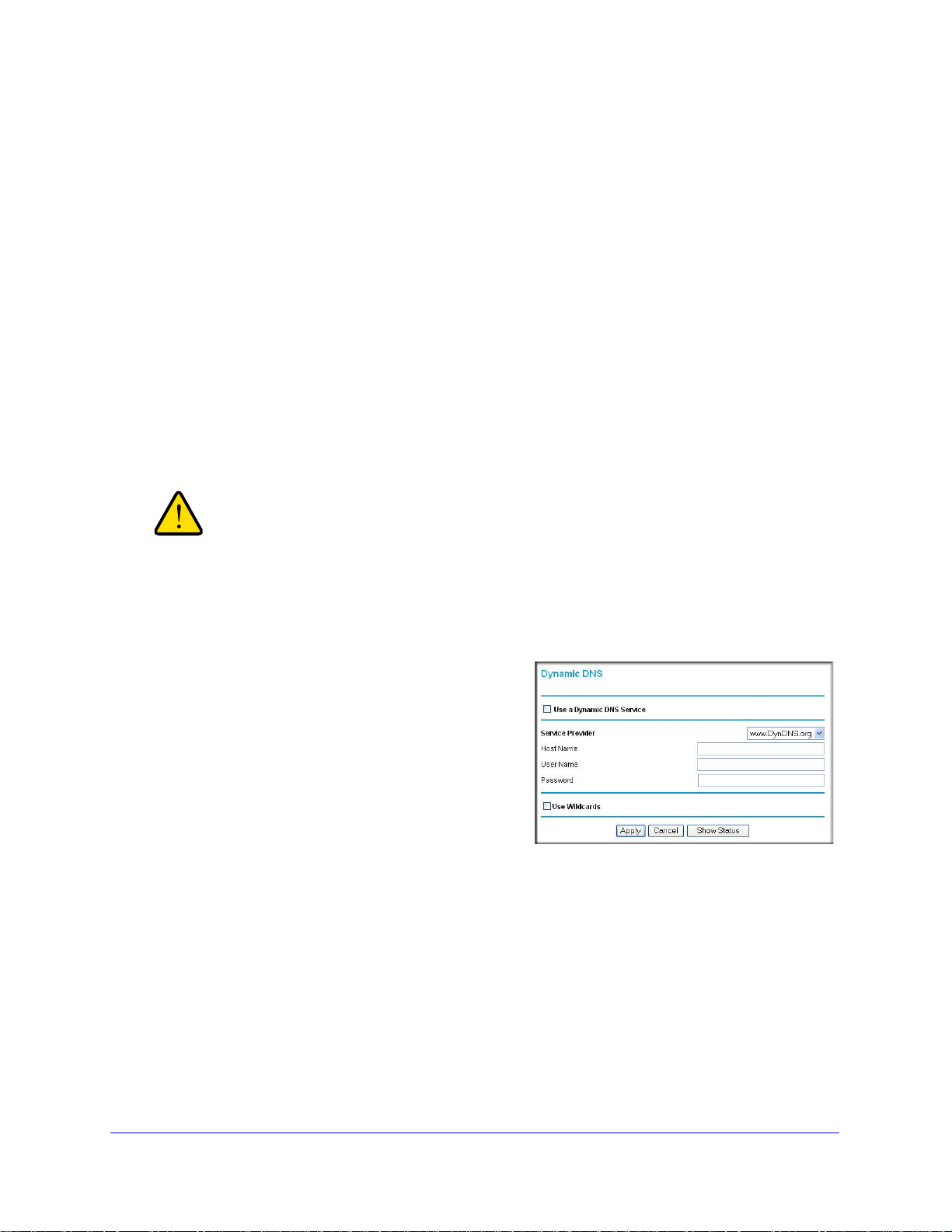
Mobile V oice HSP A+ Broadband 1 1n Wireless Router MVBR1210C
WARNING:
3. Click Apply.
Dynamic DNS
If your network has a permanently assigned IP address, you can register a domain name and
have that name linked with your IP address by public Domain Name Servers (DNS).
However , if your I nternet accoun t uses a dyn amically assig ned IP address, you will not know
in advance what your IP address will be, and the address can change frequently. In this case,
you can use a commercial Dynamic DNS service to register your domain to their IP address,
and forward traffic directed at your domain to your frequently changing IP address.
The router contains a client that can connect to a Dyn
feature, you need to select a service provider and obtain an account with them. After you
have configured your account information in the router, whenever your ISP-assigned IP
address changes, your router will automatically contact your Dynamic DNS service provider,
log in to your account, and register your new IP address.
If your ISP assigns a private WAN IP address such as 192.168.x.x
or 10.x.x.x, the Dynamic DNS service will not work because private
addresses are not routed on the Internet.
To configure Dynamic DNS:
1. From the main me
to display the Dynamic DNS screen.
2. Access the website of one of the Dynamic
DNS service providers whose names appear in
the Service Provider drop-down list, and
register for an account.
For example, for dyndns.org, go to
dyndns.org.
www.
nu, select Dynamic DNS
amic DNS service provider. To use this
3. Select the Use a Dynami
check box.
4. Select the name of your Dynamic
5. Fill in the Host Name, User Name,
The Dynamic DNS service provider might call the host name a domain name. If your URL
is myName.dynd
your Dynamic DNS account.
If your Dynamic DNS provider allows the use of wildcards in reso
select the Use wildcards check box to activate this feature.
For example, the wildcard feature will cause *.yourhost.dyndns.org to
same IP address as yourhost.dyndns.org.
ns.org, then your host name is myName. The password can be a ke y for
c DNS Service
DNS service provider.
and Password fields.
lving your URL, you can
be aliased to the
Advanced
92
Page 93

Mobile V oice HSP A+ Broadband 11n W ireless Router MVBR1210C
6. Click Apply to save your configuration.
Use Static Routes
Static routes provide additional routing information to your router. Under normal
circumstances, the router has adequate routing information after it has been configured for
Internet access, and you do not need to configure additional static routes. You need to
configure static routes only for unusual cases such as multiple routers or multiple IP subnets
located on your network.
Static Route Example
As an example of when a static route is needed, consider the following case:
• Y
our primary Internet access is through a cable modem to an ISP.
• Y
ou have an ISDN router on your home network for connecting to the company where
you are employed. This router’s address on your LAN is 192.168.0.100.
• Y
our company’s network is 134.177.0.0.
When you first configured your router
was created with your ISP as the router, and a second static route was created to your local
network for all 192.168.0.x addresses. With this configuration, if you attempt to access a
device on the 134.177.0.0 network, your router forwards your request to the ISP. The ISP
forwards your request to the company where you are employed, and the request is likely to
be denied by the company’s firewall.
In this case you need to define a static route, te
accessed through the ISDN router at 192.168.0.100.
In this example:
• The Destina
applies to all 134.177.x.x addresses.
• The Gateway IP Address f
forwarded to the ISDN router at 192.168.0.100.
• In th
• Private is se
e Metric field, a value of 1 will work since the ISDN router is on the LAN.
This represents the number of routers between you
a direct connection, so it is set to 1.
tion IP Address and IP Subnet Mask fields specify that this static route
ields specify that all traffic for these addresses should be
lected only as a precautionary security measure in case RIP is activated.
, two implicit static routes were created. A default route
lling your router that 134.177.0.0 should be
r network and the destination. This is
Advanced
93
Page 94
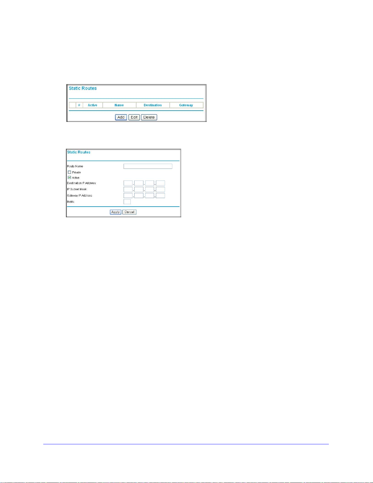
Mobile V oice HSP A+ Broadband 1 1n Wireless Router MVBR1210C
To configure static routes:
1. From the main menu, under Advanced, select Static Routes to view the Static Routes
screen.
2. Select the radio button of the static route you want to configure.
3. Click Add or Edit
to display the following screen:
4. Fill in or change the fields:
• Route Name. The
route name is for identification purposes only.
• Private. Select this check box if you want to limit access to the LAN only
The static route will not be reported in RIP.
• Active. Select this check box to make this route
• Destination IP Address a
nd IP Subnet Mask. T ype th e destination IP address of the
effective.
final destination. If the destination is a single host, type a subnet value of
255.255.255.255.
• Gateway IP Address. This needs to
be a router on the same LAN segment as the
router.
• Metric. Ty
pe a number between 2 and 15. This represents the number of routers
between your network and the destination. Usually , a setting of 2 or 3 works, but if this
is a direct connection, set it to 2.
5. Click Apply to save
your changes. If you added a static route, it is added to the Static
Routes screen.
.
Advanced
94
Page 95

Mobile V oice HSP A+ Broadband 11n W ireless Router MVBR1210C
Enable Remote Management
Using the Remote Management screen, you can allow a user or users on the Internet to
configure, upgrade, and check the status of your router.
Tip: Be sure to change the r
password. The ideal password should contain no dictionary words from
any language, and should be a mixture of letters (both uppercase and
lowercase), numbers, and symbols. Your password can be up to 30
characters.
To configure remote management:
1. Log in to the router. Type http://www.routerlogin.net in the address field of your
nternet browser. Enter admin for the user name and your password (or the default,
I
password
2. Under Advanced, select Remote Ma
3. Select the Turn Remote Management On
check box.
4. Specify which external addresses will be allowed
to access th
For security, restrict access to as few external
IP
addresses as practical:
• T
In
• To allow access from a range of IP
a
Address Range. Enter a beginning and ending IP address to define the allowed
range.
).
e router’s remote management.
o allow access from any IP address on the
ternet, select Everyone.
ddresses on the Internet, select IP
outer default password to a very secure
nagement.
• T o allow access from a single IP address on the Internet, select Only This Compute
Enter the IP address that will be allowed access.
5. S
pecify the number of the port that will
Access normally uses the standard HTTP service port 80. For
enter a different port number . Choose a number between 1024 and 65535, but do not use
the number of any common service port. The default is 8080, which is a common
alternate for HTTP.
6. Click Appl
When accessing your router from the Internet, type your router WAN IP address in your
Internet
number . For example, if your external address is 134.177.0.123 and you use port number
8080, enter http://134.177.0.123:8080. Be sure to include http:// in the address.
y to have your changes take effect.
browser address or location field, followed by a colon (:) and the custom port
be used for accessing the router menu.
greater security, you can
Advanced
95
r.
Page 96

Mobile V oice HSP A+ Broadband 1 1n Wireless Router MVBR1210C
Universal Plug and Play
Universal Plug and Play (UPnP) helps devices such as Internet appliances and computers
access the network and connect to other devices as needed. UPnP devices can
automatically discover the services from other registered UPnP devices on the network.
To configure UPnP:
1. On the main menu, select UPnP to d
2. Fill in the settings on the UPnP screen:
• Turn UPnP On.
enabled. If this feature is disabled, the router will not allow any device to a utomatically
control the resources, such as port forwarding (mapping), of the router.
• Advertis
(broadcasts) its UPnP information. This value can range from 1 to 1440 minutes. The
default period is 30 minutes. Shorter durations ensure that control points have current
device status at the expense of additional network traffic. Longer durations might
compromise the freshness of the device status but can significantly reduce network
traffic.
• Advertisement T
hops for each UPnP packet sent. Hops are the number of steps allowed to propagate
for each UPnP advertisement before it disappears. The number of hops can range
from 1 to 255. The default value for the advertisement time to live is 4 hops, which
should be fine for most home networks. If you notice that some devices are not being
updated or reached correctly, then it might be necessary to increase this value a little.
ment Period. The advertisement period is how often the router advertises
e
UPnP can be enabled or disabled. The default setting for UPnP is
ime To Live. The time to live for the advertisement is measured in
isplay the UPnP screen:
• UPnP Portmap Table. The UPnP Portmap T
UPnP device that is currently accessing the router and which ports (internal and
external) that device has opened.
3. To save or cancel your changes or refresh the table:
• Click Apply to save the n
• Click Cancel to
• Click Refre
currently opened by UPnP devices.
disregard any unsaved changes.
sh to update the portmap table and to show the active ports that are
ew settings to the router.
Advanced
96
able displays the IP address of each
Page 97

Mobile V oice HSP A+ Broadband 11n W ireless Router MVBR1210C
Traffic Meter
Traffic metering allows you to monitor the volume of Internet traffic passing through your
router’s Internet port. With the traffic meter utility, you can set limits for traffic volume, set a
monthly limit, and get a live update of traffic usage. You enable separate traffic meters for the
mobile broadband connection and the Ethernet connection.
To monitor traffic on your router:
1. Under Advanced on the router menu,
t Traffic Meter.
selec
2. Select the appropriate Show Traffic Meter
Application for radio button for the type of
Internet connection (mobile broadband or
Ethernet) you are setting up.
3. To enable the traffic meter, select the
le Traffic Meter check box.
Enab
4. If you would
volume of Internet traffic, select the Traffic
volume control by radio button. You can
select one of the following options for
controlling the traffic volume:
• No Limit. No
when the traffic limit is reached.
like to record and restrict the
restriction is applied
• Download only. Th
applied to incoming traffic only.
• Both Directions. The restrictio
applied to both incoming and outgoing
traffic.
5. You can limit the amount of data traffic
allowe
d per month by specifying:
• How many
allowed.
• How many
6. Set the traffic counter to begin at a specific
time a
nd date.
7. Set up traffic control to issue a warning message before the monthly limit of Mbytes or hours
is re
ached. You can select one of the following to occur when the limit is attained:
• The Internet Port LED flashes green or amber.
The Internet connection is disco
•
• Send an email. See Enable Secu
8. Set up Internet
9. Click the Tr
10. Click Apply to save your settings.
Mbytes per month are
hours of traffic are allowed.
traffic statistics to monitor the data traffic.
affic Status button for a live update on Internet traffic status on your router.
e restriction is
n is
nnected and disabled.
rity Event Email Notification on page 62.
Advanced
97
Page 98

9. Troubleshooting
This chapter gives information about troubleshooting your Mobile Voice HSPA+ Broadband 11n
Wireless Router. After each problem description, instructions are provided to help you diagnose
and solve the problem. For the common problems listed, go to the section indicated.
9
• Is
• Have
• I can’t
• I’ve config
• I’ve config
• How do I set da
• I want
the router on?
Go to Basic Functioning on p
I connected the router correctly?
Go to Basic Functioning on p
access the router’s configuration with my browser.
Go to Troubleshoot Access to the Router Main Menu on p
ured the router but I can’t access the Internet.
Go to Troubleshoot the ISP Connection on
ured the router but I can’t access my local network.
Go to Troubleshoot a TCP/IP Network Using the Ping Utility o
ylight savings time?
Go to Problems with Date and Time on p
to clear the configuration and start over again.
Go to Restore the Default Configuration and Password o
age 99.
age 99.
page 102.
age 105.
age 101.
n page 104.
n page 106.
98
Page 99

Mobile V oice HSP A+ Broadband 11n W ireless Router MVBR1210C
Basic Functioning
After you turn on power to the router, the following sequence of events should occur:
1. When power is first applied, verify that the Power
LED is on.
2. After approximately a minute, verify that:
a. The Power LED is still solid green. An amber light indicates the unit has failed its
p
ower-on self-test (POST).
b. The Internet Port LED is lit.
The WiFi LED is lit. The WiFi radio is on by default.
c.
d.
The LAN Ports LED is lit when any local ports are connected.
I
f a LAN Port LED on the back of the unit is lit, a link has been established to the
connected
device. If a LAN port is connected to a 100 Mbps device, verify that the
port’s LED is green. If the port is 10 Mbps, the LED is amber.
e. The WAN Port LED is lit when the router is connected to a wired modem.
f. One of the Signal Quality LEDs is lit when the router has detected a mobile
b
roadband signal.
• The blue
• The blue
• The blue
If any of these conditions does not occur, refe
LED indicates excellent coverage.
LED indicates good coverage.
LED indicates marginal coverage.
r to the following table.
LED Action
Power Power LED is off. • Make sure the power cord is correctly connected to your router, and that
the power supply adapter is correctly connecte d to a functioning power
outlet.
lied by NETGEAR for
s. This sets the router’s
e 106.
Power LED is
r.
ambe
• Check that you are using the power adapter supp
this product.
• If the error persists, you might have a hardware problem and should
contact techn
There is a fault within the router. Try to clear the fault as follows:
• Cycle the power to see if the router recovers.
• Clear the router’s configuration to fa ctory default
IP address to 192.168.0.1. This procedure is explained in Restore the
Default Configuration and Password on pag
If the error persists, you might have a hardware problem and should contact
technical suppo
ical support.
rt.
Troubleshooting
99
Page 100

Mobile V oice HSP A+ Broadband 1 1n Wireless Router MVBR1210C
LED Action
Internet Port Internet Port LED is
off.
Internet Port LED is
amber.
Internet Port LED is
nking amber and
bli
green.
WiFi
LAN Ports
WiFi LED is off. The WiFi radio has been turned off. If you want a WiFi connection with the
WiFi LED is not
blinking.
LAN Ports LED is
off.
Be sure the SIM card you received is in the router. SIM cards from other
devices will not function in the router, and this SIM card will not function in
other devices.
router cannot connect to the Internet. Check the Internet connection
The
option being used.
• For the mobile broadband connection option , check the Signal Quality
LEDs.
• For the Ethernet connection option, check the WAN Port LED.
The traffic meter feature is enabled, and the limit set has been reached.
router, press the WiFi button to turn the WiFi radio back on.
If this LED does not blink when you are attempting to send data over the
WiFi link, log in to the router menu using the Ethernet LAN connection, and
check your router’s wireless (WiFi) configuration.
If this LED does not light when an Ethernet connection is made, check the
following:
• Make sure that the Ethernet cable connectio
and at the hub or workstation.
• Make sure that power is turned on to the connected h
ns are secure at the router
ub or workstation.
WAN Port
Signal
Quality
WAN Port LED is
off.
Signal Quality LEDs
are off.
If this LED does not light when an Ethernet connection is made using the
Ethernet connection option, check the following:
• Make sure that the Ethernet cable connectio
and at the modem.
• Make sure that power is turned on to the modem.
If these LEDs do not light when the mobile broadband connection option is
used, check the following:
• Check with your ISP to ensure that ther
• Ensure that your mobile broadband account is active.
• Ensure that the SIM card is inserted correctly into the router
• Locate the router near the window or other area of the buil
sure that one of the Signal Quality LEDs is lit, indicating that th ere is
mobile broadband coverage with the router.
• Log in to the router menu and check the Internet configuration. Check that
the user name, password, and APN with ISP are set correctly. If you use
a PIN to connect to the Internet, make sure it is entered correctly.
ns are secure at the router
e is good coverage in the area.
.
ding. Make
Troubleshooting
100
 Loading...