

Page 1

User Manual
8-Port Multi-Gigabit Smart Managed
Pro
Switch with Two 10G Ports
MS510TX and MS510TXPP
User Manual
July 2019
202-11762-04
NETGEAR, Inc.
350 East Plumeria Drive
San Jose, CA 95134, USA
Page 2

Smart Managed Pro Switches MS510TX and MS510TXPP
User Manual2
Page 3

Smart Managed Pro Switches MS510TX and MS510TXPP
Support
Thank you for purchasing this NETGEAR product. You can visit www.netgear.com/support to register your product,
get help, access the latest downloads and user manuals, and join our community. We recommend that you use
only official NETGEAR support resources.
Conformity
For the current EU Declaration of Conformity, visit http://kb.netgear.com/app/answers/detail/a_id/11621.
Compliance
For regulatory compliance information, visit http://www.netgear.com/about/regulatory.
See the regulatory compliance document before connecting the power supply.
Do not use this device outdoors. If you connect cables or devices that are outdoors to this device, see
http://kb.netgear.com/000057103 for safety and warranty information.
Trademarks
© NETGEAR, Inc., NETGEAR and the NETGEAR Logo are trademarks of NETGEAR, Inc. Any non-NETGEAR
trademarks are used for reference purposes only.
Revision History
Publication Part Number Publish Date Comments
202-11762-03 June 2018 Updated
202-11762-02 September 2017 Made minor changes and corrections.
202-11762-01 September 2017 First publication.
Configure VLAN Settings.
User Manual3
Page 4

Contents
Chapter 1 Get Started
Chapter 2 Configure System Information
Switch Descriptions . . . . . . . . . . . . . . . . . . . . . . . . . . . . . . . . . . . . . . . . . . . . . .11
Available Publications . . . . . . . . . . . . . . . . . . . . . . . . . . . . . . . . . . . . . . . . . . . .11
Switch Management Methods . . . . . . . . . . . . . . . . . . . . . . . . . . . . . . . . . . . . . 11
Web Browser Requirements and Supported Browsers . . . . . . . . . . . . . . . . 12
User-Defined Fields . . . . . . . . . . . . . . . . . . . . . . . . . . . . . . . . . . . . . . . . . . . . . . 13
Interface Naming Conventions. . . . . . . . . . . . . . . . . . . . . . . . . . . . . . . . . . . . . 13
Access the Switch . . . . . . . . . . . . . . . . . . . . . . . . . . . . . . . . . . . . . . . . . . . . . . . . 14
Access the Switch On-Network With a DHCP Server . . . . . . . . . . . . . . .14
Access the Switch On-Network Without a DHCP Server . . . . . . . . . . . .16
Access the Switch Off-Network. . . . . . . . . . . . . . . . . . . . . . . . . . . . . . . . . .18
Register the Switch . . . . . . . . . . . . . . . . . . . . . . . . . . . . . . . . . . . . . . . . . . . . . . . 19
How to Configure Interface Settings . . . . . . . . . . . . . . . . . . . . . . . . . . . . . . . . 19
Local Browser Interface Device View . . . . . . . . . . . . . . . . . . . . . . . . . . . . . . . .21
View and Configure the Switch Management Settings. . . . . . . . . . . . . . . .26
View or Define System Information and View Software Versions . . . . .26
View the System CPU Status . . . . . . . . . . . . . . . . . . . . . . . . . . . . . . . . . . . .28
View USB Device Information . . . . . . . . . . . . . . . . . . . . . . . . . . . . . . . . . . .29
Configure the IPv4 Address for the Network Interface and
Management VLAN. . . . . . . . . . . . . . . . . . . . . . . . . . . . . . . . . . . . . . . . . . . .30
Configure the IPv6 Address for the Network Interface . . . . . . . . . . . . . .32
View the IPv6 Network Neighbor . . . . . . . . . . . . . . . . . . . . . . . . . . . . . . . .33
Configure the Time Settings . . . . . . . . . . . . . . . . . . . . . . . . . . . . . . . . . . . .34
Configure DNS Settings . . . . . . . . . . . . . . . . . . . . . . . . . . . . . . . . . . . . . . . .44
Configure Green Ethernet Settings . . . . . . . . . . . . . . . . . . . . . . . . . . . . . .47
Use the Device View. . . . . . . . . . . . . . . . . . . . . . . . . . . . . . . . . . . . . . . . . . . . . . 52
Configure Power over Ethernet . . . . . . . . . . . . . . . . . . . . . . . . . . . . . . . . . . . . 53
PoE Overview . . . . . . . . . . . . . . . . . . . . . . . . . . . . . . . . . . . . . . . . . . . . . . . . .53
Device Class Power Requirements . . . . . . . . . . . . . . . . . . . . . . . . . . . . . . .54
Power Allocation and Power Budget . . . . . . . . . . . . . . . . . . . . . . . . . . . . .54
Configure the Global PoE Settings. . . . . . . . . . . . . . . . . . . . . . . . . . . . . . .56
Manage and View the PoE Port Configuration . . . . . . . . . . . . . . . . . . . . .57
Configure SNMP. . . . . . . . . . . . . . . . . . . . . . . . . . . . . . . . . . . . . . . . . . . . . . . . . 59
Configure the SNMPv1/v2 Community . . . . . . . . . . . . . . . . . . . . . . . . . . .60
Configure SNMPv1/v2 Trap Settings . . . . . . . . . . . . . . . . . . . . . . . . . . . . .62
Configure SNMPv1/v2 Trap Flags. . . . . . . . . . . . . . . . . . . . . . . . . . . . . . . .64
View the Supported MIBs. . . . . . . . . . . . . . . . . . . . . . . . . . . . . . . . . . . . . . .65
4
Page 5

Smart Managed Pro Switches MS510TX and MS510TXPP
Configure SNMPv3 Users. . . . . . . . . . . . . . . . . . . . . . . . . . . . . . . . . . . . . . .65
Configure LLDP. . . . . . . . . . . . . . . . . . . . . . . . . . . . . . . . . . . . . . . . . . . . . . . . . . 66
Configure LLDP Global Settings . . . . . . . . . . . . . . . . . . . . . . . . . . . . . . . . .67
Configure LLDP Port Settings . . . . . . . . . . . . . . . . . . . . . . . . . . . . . . . . . . .68
LLDP-MED Network Policy . . . . . . . . . . . . . . . . . . . . . . . . . . . . . . . . . . . . . .70
LLDP-MED Port Settings . . . . . . . . . . . . . . . . . . . . . . . . . . . . . . . . . . . . . . . .71
Local Information. . . . . . . . . . . . . . . . . . . . . . . . . . . . . . . . . . . . . . . . . . . . . .72
Neighbors Information . . . . . . . . . . . . . . . . . . . . . . . . . . . . . . . . . . . . . . . . .74
Configure DHCP Snooping. . . . . . . . . . . . . . . . . . . . . . . . . . . . . . . . . . . . . . . . 77
Configure the Global DHCP Snooping Settings. . . . . . . . . . . . . . . . . . . .78
Enable DHCP for All Interfaces in a VLAN . . . . . . . . . . . . . . . . . . . . . . . . .79
Configure DHCP Snooping Interface Settings . . . . . . . . . . . . . . . . . . . . .79
Configure Static DHCP Bindings. . . . . . . . . . . . . . . . . . . . . . . . . . . . . . . . .80
Configure the DHCP Snooping Persistent Settings . . . . . . . . . . . . . . . . .82
Set Up PoE Timer Schedules. . . . . . . . . . . . . . . . . . . . . . . . . . . . . . . . . . . . . . . 82
Create a PoE Timer Schedule . . . . . . . . . . . . . . . . . . . . . . . . . . . . . . . . . . .83
Specify the Settings for a PoE Timer Schedule . . . . . . . . . . . . . . . . . . . . .84
Add a Periodic Schedule for a PoE Timer Schedule . . . . . . . . . . . . . . . .85
Delete a Periodic Schedule for a PoE Timer Schedule . . . . . . . . . . . . . .86
Delete a PoE Timer Schedule . . . . . . . . . . . . . . . . . . . . . . . . . . . . . . . . . . .87
Chapter 3 Configure Switching
Configure Port Settings and Flow Control . . . . . . . . . . . . . . . . . . . . . . . . . . .89
Configure IEEE 802.3x Global Flow Control. . . . . . . . . . . . . . . . . . . . . . .89
Configure the Port Settings . . . . . . . . . . . . . . . . . . . . . . . . . . . . . . . . . . . . .90
Configure Link Aggregation Groups . . . . . . . . . . . . . . . . . . . . . . . . . . . . . . . .91
Configure LAG Settings . . . . . . . . . . . . . . . . . . . . . . . . . . . . . . . . . . . . . . . .92
Configure LAG Membership . . . . . . . . . . . . . . . . . . . . . . . . . . . . . . . . . . . .94
Set the LACP System Priority . . . . . . . . . . . . . . . . . . . . . . . . . . . . . . . . . . . .95
Set the LACP Port Priority Settings . . . . . . . . . . . . . . . . . . . . . . . . . . . . . . .95
Configure VLANs . . . . . . . . . . . . . . . . . . . . . . . . . . . . . . . . . . . . . . . . . . . . . . . .96
Configure VLAN Settings . . . . . . . . . . . . . . . . . . . . . . . . . . . . . . . . . . . . . . .97
Configure VLAN Membership. . . . . . . . . . . . . . . . . . . . . . . . . . . . . . . . . . .99
View VLAN Status. . . . . . . . . . . . . . . . . . . . . . . . . . . . . . . . . . . . . . . . . . . . 101
Configure Port PVID Settings. . . . . . . . . . . . . . . . . . . . . . . . . . . . . . . . . . 102
Configure MAC-Based VLAN Groups . . . . . . . . . . . . . . . . . . . . . . . . . . 104
Manually Add Members to or Remove Them From a MAC-Based
VLAN Group . . . . . . . . . . . . . . . . . . . . . . . . . . . . . . . . . . . . . . . . . . . . . . . . 106
Configure Protocol-Based VLAN Groups . . . . . . . . . . . . . . . . . . . . . . . 106
Manually Add Members to or Remove Them From a
Protocol-Based VLAN Group . . . . . . . . . . . . . . . . . . . . . . . . . . . . . . . . . . 108
Configure GARP Switch Settings. . . . . . . . . . . . . . . . . . . . . . . . . . . . . . . 109
Configure GARP Ports. . . . . . . . . . . . . . . . . . . . . . . . . . . . . . . . . . . . . . . . 110
Configure a Voice VLAN . . . . . . . . . . . . . . . . . . . . . . . . . . . . . . . . . . . . . . . . .112
Configure the Global Voice VLAN Settings. . . . . . . . . . . . . . . . . . . . . . 112
Configure Membership for the Voice VLAN . . . . . . . . . . . . . . . . . . . . . 113
Manage the OUI Table . . . . . . . . . . . . . . . . . . . . . . . . . . . . . . . . . . . . . . . 114
Configure Auto-VoIP. . . . . . . . . . . . . . . . . . . . . . . . . . . . . . . . . . . . . . . . . . . . .116
User Manual5
Page 6

Smart Managed Pro Switches MS510TX and MS510TXPP
Configure Spanning Tree Protocol. . . . . . . . . . . . . . . . . . . . . . . . . . . . . . . . .117
Configure STP Settings. . . . . . . . . . . . . . . . . . . . . . . . . . . . . . . . . . . . . . . 118
Configure CST Settings . . . . . . . . . . . . . . . . . . . . . . . . . . . . . . . . . . . . . . 120
Configure CST Port Settings . . . . . . . . . . . . . . . . . . . . . . . . . . . . . . . . . . 122
View the CST Port Status. . . . . . . . . . . . . . . . . . . . . . . . . . . . . . . . . . . . . . 123
View Rapid STP Information. . . . . . . . . . . . . . . . . . . . . . . . . . . . . . . . . . . 124
Manage MST Settings. . . . . . . . . . . . . . . . . . . . . . . . . . . . . . . . . . . . . . . . 125
Configure MST Port Settings . . . . . . . . . . . . . . . . . . . . . . . . . . . . . . . . . . 128
View STP Statistics . . . . . . . . . . . . . . . . . . . . . . . . . . . . . . . . . . . . . . . . . . . 130
Configure Multicast . . . . . . . . . . . . . . . . . . . . . . . . . . . . . . . . . . . . . . . . . . . . .131
View the MFDB Table . . . . . . . . . . . . . . . . . . . . . . . . . . . . . . . . . . . . . . . . 132
View the MFDB Statistics . . . . . . . . . . . . . . . . . . . . . . . . . . . . . . . . . . . . . 133
Configure Auto-Video. . . . . . . . . . . . . . . . . . . . . . . . . . . . . . . . . . . . . . . . 134
IGMP Snooping Overview . . . . . . . . . . . . . . . . . . . . . . . . . . . . . . . . . . . . 135
Configure the Global IGMP Snooping Settings . . . . . . . . . . . . . . . . . . 135
View the IGMP Snooping Table. . . . . . . . . . . . . . . . . . . . . . . . . . . . . . . . 137
Configure IGMP Snooping for VLANs . . . . . . . . . . . . . . . . . . . . . . . . . . 138
Modify IGMP Snooping Settings for a VLAN. . . . . . . . . . . . . . . . . . . . . 139
Disable IGMP Snooping on a VLAN and Remove It From the Table . 139
IGMP Snooping Querier Overview. . . . . . . . . . . . . . . . . . . . . . . . . . . . . 140
Configure IGMP Snooping Querier . . . . . . . . . . . . . . . . . . . . . . . . . . . . 140
Configure IGMP Snooping Querier for VLANs. . . . . . . . . . . . . . . . . . . 141
Display the IGMP Snooping Querier for VLAN Status. . . . . . . . . . . . . 142
MLD Snooping Overview. . . . . . . . . . . . . . . . . . . . . . . . . . . . . . . . . . . . . 143
Configure the Global MLD Snooping Settings. . . . . . . . . . . . . . . . . . . 144
Configure MLD Snooping for a VLAN. . . . . . . . . . . . . . . . . . . . . . . . . . . . . .144
Configure a Multicast Router Interface on a VLAN. . . . . . . . . . . . . . . . 146
Configure MLD Snooping Querier. . . . . . . . . . . . . . . . . . . . . . . . . . . . . 147
Configure MLD Snooping Querier VLAN Settings. . . . . . . . . . . . . . . . 148
Configure a Multicast Group . . . . . . . . . . . . . . . . . . . . . . . . . . . . . . . . . . 149
Remove a Multicast Group. . . . . . . . . . . . . . . . . . . . . . . . . . . . . . . . . . . . 150
Configure Multicast Group Membership. . . . . . . . . . . . . . . . . . . . . . . . 151
Configure the Multicast Forward All Option . . . . . . . . . . . . . . . . . . . . . 152
View, Search, and Manage the MAC Address Table. . . . . . . . . . . . . . . . . .153
View and Search the MAC Address Table . . . . . . . . . . . . . . . . . . . . . . . 154
Change the Aging-Out Period of Dynamic MAC Addresses . . . . . . . 155
Add a Static MAC Address. . . . . . . . . . . . . . . . . . . . . . . . . . . . . . . . . . . . 156
Remove a Static MAC Address . . . . . . . . . . . . . . . . . . . . . . . . . . . . . . . . 156
Chapter 4 Configure Routing
IP Routing Overview . . . . . . . . . . . . . . . . . . . . . . . . . . . . . . . . . . . . . . . . . . . 159
Configure IP Settings . . . . . . . . . . . . . . . . . . . . . . . . . . . . . . . . . . . . . . . . . . . .159
Configure the Routing Settings. . . . . . . . . . . . . . . . . . . . . . . . . . . . . . . . 159
View the IP Statistics . . . . . . . . . . . . . . . . . . . . . . . . . . . . . . . . . . . . . . . . . 160
Configure VLAN Routing. . . . . . . . . . . . . . . . . . . . . . . . . . . . . . . . . . . . . . . . .163
Use the VLAN Static Routing Wizard . . . . . . . . . . . . . . . . . . . . . . . . . . . 164
VLAN Routing Configuration. . . . . . . . . . . . . . . . . . . . . . . . . . . . . . . . . . 165
User Manual6
Page 7

Smart Managed Pro Switches MS510TX and MS510TXPP
Manage IPv4 Routes. . . . . . . . . . . . . . . . . . . . . . . . . . . . . . . . . . . . . . . . . . . . .166
Configure Address Resolution Protocol . . . . . . . . . . . . . . . . . . . . . . . . . . . .168
Display the ARP Cache . . . . . . . . . . . . . . . . . . . . . . . . . . . . . . . . . . . . . . . 168
Add an Entry to the ARP Table . . . . . . . . . . . . . . . . . . . . . . . . . . . . . . . . 169
Configure the Global Aging-Out Time for ARP . . . . . . . . . . . . . . . . . . 170
Remove an ARP Entry From the ARP Cache . . . . . . . . . . . . . . . . . . . . . 171
Configure IPv6 . . . . . . . . . . . . . . . . . . . . . . . . . . . . . . . . . . . . . . . . . . . . . . . . 173
Configure IPv6 Global Settings. . . . . . . . . . . . . . . . . . . . . . . . . . . . . . . . 173
Add a Static IPv6 Route. . . . . . . . . . . . . . . . . . . . . . . . . . . . . . . . . . . . . . . 174
Change the Preference for a Static IPv6 Route . . . . . . . . . . . . . . . . . . . 175
Remove a Static IPv6 Route . . . . . . . . . . . . . . . . . . . . . . . . . . . . . . . . . . . 176
View the IPv6 Route Table . . . . . . . . . . . . . . . . . . . . . . . . . . . . . . . . . . . . 177
Configure IPv6 VLAN Interface Settings . . . . . . . . . . . . . . . . . . . . . . . . 178
Add an IPv6 Global Address to an IPv6 VLAN . . . . . . . . . . . . . . . . . . . 180
Change the Settings for an IPv6 Global Address on an IPv6 VLAN. . 182
Remove an IPv6 Global Address From an IPv6 VLAN . . . . . . . . . . . . . 183
Add an IPv6 Prefix for Advertisement on an IPv6 VLAN . . . . . . . . . . . 183
Change the Settings for an IPv6 Prefix for Advertisement on
an IPv6 VLAN . . . . . . . . . . . . . . . . . . . . . . . . . . . . . . . . . . . . . . . . . . . . . . . 185
Remove an IPv6 Prefix From an IPv6 VLAN . . . . . . . . . . . . . . . . . . . . . . 185
View IPv6 Statistics for an Interface. . . . . . . . . . . . . . . . . . . . . . . . . . . . . 186
View or Clear the IPv6 Neighbor Table . . . . . . . . . . . . . . . . . . . . . . . . . 188
Chapter 5 Configure Quality of Service
Manage Class of Service. . . . . . . . . . . . . . . . . . . . . . . . . . . . . . . . . . . . . . . . 191
CoS Configuration. . . . . . . . . . . . . . . . . . . . . . . . . . . . . . . . . . . . . . . . . . . 191
Configure Global CoS Settings . . . . . . . . . . . . . . . . . . . . . . . . . . . . . . . . 192
Configure CoS Interface Settings for an Interface . . . . . . . . . . . . . . . . 192
Configure the Global CoS Queue Settings. . . . . . . . . . . . . . . . . . . . . . 194
Configure the Global 802.1p to Queue Mapping . . . . . . . . . . . . . . . . 195
DSCP to Queue Mapping . . . . . . . . . . . . . . . . . . . . . . . . . . . . . . . . . . . . 196
Manage Differentiated Services . . . . . . . . . . . . . . . . . . . . . . . . . . . . . . . . . . .197
DiffServ Overview . . . . . . . . . . . . . . . . . . . . . . . . . . . . . . . . . . . . . . . . . . . 198
View the Global DiffServ Resources . . . . . . . . . . . . . . . . . . . . . . . . . . . . 199
Specify DSCP Remark Values for Violate Action IP Packets. . . . . . . . . 199
Configure IPv4 DiffServ Classes . . . . . . . . . . . . . . . . . . . . . . . . . . . . . . . 201
Configure an IPv6 DiffServ IPv6 Classes . . . . . . . . . . . . . . . . . . . . . . . . 205
Configure a DiffServ Policy. . . . . . . . . . . . . . . . . . . . . . . . . . . . . . . . . . . . 209
Configure DiffServ Service Interfaces. . . . . . . . . . . . . . . . . . . . . . . . . . . 214
View DiffServ Service Statistics . . . . . . . . . . . . . . . . . . . . . . . . . . . . . . . . 215
Chapter 6 Manage Device Security
Management Security Settings . . . . . . . . . . . . . . . . . . . . . . . . . . . . . . . . . . 218
Change the Password . . . . . . . . . . . . . . . . . . . . . . . . . . . . . . . . . . . . . . . . 218
Reset the Password to the Factory Default Value . . . . . . . . . . . . . . . . . 219
Configure RADIUS Servers. . . . . . . . . . . . . . . . . . . . . . . . . . . . . . . . . . . . 220
Configure TACACS+ Servers . . . . . . . . . . . . . . . . . . . . . . . . . . . . . . . . . . 226
User Manual7
Page 8

Smart Managed Pro Switches MS510TX and MS510TXPP
Configure Authentication Lists . . . . . . . . . . . . . . . . . . . . . . . . . . . . . . . . 229
Configure Management Access. . . . . . . . . . . . . . . . . . . . . . . . . . . . . . . . . . .232
Configure HTTP Settings . . . . . . . . . . . . . . . . . . . . . . . . . . . . . . . . . . . . . 232
Configure HTTPS Settings . . . . . . . . . . . . . . . . . . . . . . . . . . . . . . . . . . . . 233
Manage the Certificate . . . . . . . . . . . . . . . . . . . . . . . . . . . . . . . . . . . . . . . 234
Configure Access Control . . . . . . . . . . . . . . . . . . . . . . . . . . . . . . . . . . . . 237
Configure Port Authentication . . . . . . . . . . . . . . . . . . . . . . . . . . . . . . . . . . . 243
Configure Global 802.1X Settings . . . . . . . . . . . . . . . . . . . . . . . . . . . . . 243
Manage Port Authentication . . . . . . . . . . . . . . . . . . . . . . . . . . . . . . . . . . 245
View the Port Summary. . . . . . . . . . . . . . . . . . . . . . . . . . . . . . . . . . . . . . . 247
View the Client Summary . . . . . . . . . . . . . . . . . . . . . . . . . . . . . . . . . . . . . 249
Set Up Traffic Control . . . . . . . . . . . . . . . . . . . . . . . . . . . . . . . . . . . . . . . . . . 250
Configure Storm Control . . . . . . . . . . . . . . . . . . . . . . . . . . . . . . . . . . . . . 250
Configure Port Security. . . . . . . . . . . . . . . . . . . . . . . . . . . . . . . . . . . . . . . 251
Configure Protected Ports . . . . . . . . . . . . . . . . . . . . . . . . . . . . . . . . . . . . 254
Configure Private VLANs . . . . . . . . . . . . . . . . . . . . . . . . . . . . . . . . . . . . . 254
Configure Access Control Lists. . . . . . . . . . . . . . . . . . . . . . . . . . . . . . . . . . . .259
Use the ACL Wizard to Create a Simple ACL . . . . . . . . . . . . . . . . . . . . 260
Configure a Basic MAC ACL . . . . . . . . . . . . . . . . . . . . . . . . . . . . . . . . . . 265
Configure MAC ACL Rules. . . . . . . . . . . . . . . . . . . . . . . . . . . . . . . . . . . . 267
Configure MAC Bindings . . . . . . . . . . . . . . . . . . . . . . . . . . . . . . . . . . . . . 271
View or Delete MAC ACL Bindings in the MAC Binding Table . . . . . 273
Configure an IP ACL . . . . . . . . . . . . . . . . . . . . . . . . . . . . . . . . . . . . . . . . . 274
Configure Rules for a Basic IP ACL . . . . . . . . . . . . . . . . . . . . . . . . . . . . . 275
Configure Rules for an Extended IP ACL . . . . . . . . . . . . . . . . . . . . . . . . 278
Configure an IPv6 ACL . . . . . . . . . . . . . . . . . . . . . . . . . . . . . . . . . . . . . . . 283
Configure IPv6 Rules. . . . . . . . . . . . . . . . . . . . . . . . . . . . . . . . . . . . . . . . . 284
Configure IP ACL Interface Bindings . . . . . . . . . . . . . . . . . . . . . . . . . . . 288
View or Delete IP ACL Bindings in the IP ACL Binding Table . . . . . . . 290
Chapter 7 Monitor the System
Monitor the Switch and the Ports . . . . . . . . . . . . . . . . . . . . . . . . . . . . . . . . 293
Switch Statistics . . . . . . . . . . . . . . . . . . . . . . . . . . . . . . . . . . . . . . . . . . . . . 293
View Port Statistics. . . . . . . . . . . . . . . . . . . . . . . . . . . . . . . . . . . . . . . . . . . 294
View Detailed Port Statistics. . . . . . . . . . . . . . . . . . . . . . . . . . . . . . . . . . . 297
View EAP Statistics. . . . . . . . . . . . . . . . . . . . . . . . . . . . . . . . . . . . . . . . . . . 300
Perform a Cable Test . . . . . . . . . . . . . . . . . . . . . . . . . . . . . . . . . . . . . . . . . 302
Configure and View Logs . . . . . . . . . . . . . . . . . . . . . . . . . . . . . . . . . . . . . . . .303
Manage the Buffered Logs. . . . . . . . . . . . . . . . . . . . . . . . . . . . . . . . . . . . 304
Manage the Flash Log . . . . . . . . . . . . . . . . . . . . . . . . . . . . . . . . . . . . . . . 305
Manage the Server Log . . . . . . . . . . . . . . . . . . . . . . . . . . . . . . . . . . . . . . 307
View the Trap Logs . . . . . . . . . . . . . . . . . . . . . . . . . . . . . . . . . . . . . . . . . . 309
Configure Port Mirroring . . . . . . . . . . . . . . . . . . . . . . . . . . . . . . . . . . . . . . . . .310
View the System Resource Utilization . . . . . . . . . . . . . . . . . . . . . . . . . . . . . .311
User Manual8
Page 9

Smart Managed Pro Switches MS510TX and MS510TXPP
Chapter 8 Maintain the Switch and Perform Troubleshooting
Reboot the Switch . . . . . . . . . . . . . . . . . . . . . . . . . . . . . . . . . . . . . . . . . . . . . 314
Reset the Switch to Its Factory Default Settings . . . . . . . . . . . . . . . . . . . . . .314
Export a File From the Switch . . . . . . . . . . . . . . . . . . . . . . . . . . . . . . . . . . . . .315
Export a File to the TFTP Server . . . . . . . . . . . . . . . . . . . . . . . . . . . . . . . 315
HTTP File Export . . . . . . . . . . . . . . . . . . . . . . . . . . . . . . . . . . . . . . . . . . . . 317
Export a File From the Switch to a USB Device. . . . . . . . . . . . . . . . . . . 318
Download a File to the Switch . . . . . . . . . . . . . . . . . . . . . . . . . . . . . . . . . . . .319
Download a File to the Switch Using TFTP . . . . . . . . . . . . . . . . . . . . . . 319
Download a File to the Switch Using HTTP . . . . . . . . . . . . . . . . . . . . . . 321
Download a File From a USB Device . . . . . . . . . . . . . . . . . . . . . . . . . . . 322
Manage Files . . . . . . . . . . . . . . . . . . . . . . . . . . . . . . . . . . . . . . . . . . . . . . . . . . .323
Change the Image That Loads During the Boot Process . . . . . . . . . . 323
View the Dual Image Status . . . . . . . . . . . . . . . . . . . . . . . . . . . . . . . . . . . 324
Troubleshooting . . . . . . . . . . . . . . . . . . . . . . . . . . . . . . . . . . . . . . . . . . . . . . . .325
Ping an IPv4 Address . . . . . . . . . . . . . . . . . . . . . . . . . . . . . . . . . . . . . . . . 325
Ping an IPv6 Address . . . . . . . . . . . . . . . . . . . . . . . . . . . . . . . . . . . . . . . . 328
Send an IPv4 Traceroute . . . . . . . . . . . . . . . . . . . . . . . . . . . . . . . . . . . . . . 329
Send an IPv6 Traceroute . . . . . . . . . . . . . . . . . . . . . . . . . . . . . . . . . . . . . . 330
Generate Technical Support Information. . . . . . . . . . . . . . . . . . . . . . . . 331
Enable Remote Diagnostics. . . . . . . . . . . . . . . . . . . . . . . . . . . . . . . . . . . 332
Appendix A Configuration Examples
Virtual Local Area Networks (VLANs) . . . . . . . . . . . . . . . . . . . . . . . . . . . . . 334
VLAN Configuration Examples . . . . . . . . . . . . . . . . . . . . . . . . . . . . . . . . 335
Access Control Lists (ACLs) . . . . . . . . . . . . . . . . . . . . . . . . . . . . . . . . . . . . . . .336
Sample MAC ACL Configuration . . . . . . . . . . . . . . . . . . . . . . . . . . . . . . 336
Sample Standard IP ACL Configuration. . . . . . . . . . . . . . . . . . . . . . . . . 337
Differentiated Services (DiffServ) . . . . . . . . . . . . . . . . . . . . . . . . . . . . . . . . . .338
Class. . . . . . . . . . . . . . . . . . . . . . . . . . . . . . . . . . . . . . . . . . . . . . . . . . . . . . . 339
DiffServ Traffic Classes . . . . . . . . . . . . . . . . . . . . . . . . . . . . . . . . . . . . . . . 339
Creating Policies . . . . . . . . . . . . . . . . . . . . . . . . . . . . . . . . . . . . . . . . . . . . 340
DiffServ Example Configuration . . . . . . . . . . . . . . . . . . . . . . . . . . . . . . . 341
802.1X. . . . . . . . . . . . . . . . . . . . . . . . . . . . . . . . . . . . . . . . . . . . . . . . . . . . . . . . .342
802.1X Example Configuration. . . . . . . . . . . . . . . . . . . . . . . . . . . . . . . . 344
MSTP . . . . . . . . . . . . . . . . . . . . . . . . . . . . . . . . . . . . . . . . . . . . . . . . . . . . . . . . . .345
MSTP Example Configuration . . . . . . . . . . . . . . . . . . . . . . . . . . . . . . . . . 347
VLAN Routing Interface Configuration Example. . . . . . . . . . . . . . . . . . . . .349
Appendix B Hardware Specifications and Default Settings
Hardware Specifications. . . . . . . . . . . . . . . . . . . . . . . . . . . . . . . . . . . . . . . . 352
Switch Default Settings . . . . . . . . . . . . . . . . . . . . . . . . . . . . . . . . . . . . . . . . . 353
User Manual9
Page 10

1
1Get Started
This manual describes how you can configure and monitor the following NETGEAR switches by
using the local browser–based management interface:
• MS510TX. 8-Port Multi-Gigabit Smart Managed Pro Switch with two 10G Ports, Model
MS510TX
• MS510TXPP. 8-Port Multi-Gigabit Smart Managed Pro Switch with PoE+ and two 10G
Ports, Model MS510TXPP
This chapter contains the following sections:
• Switch Descriptions
• Available Publications
• Switch Management Methods
• Web Browser Requirements and Supported Browsers
• User-Defined Fields
• Interface Naming Conventions
• Access the Switch
• Register the Switch
• How to Configure Interface Settings
• Local Browser Interface Device View
In this manual, we refer to both switch models as the switch. Unless noted otherwise, all
information applies to both switch models.
For more information about the topics covered in this manual, visit the support website at
netgear.com/support.
Firmware updates with new features and bug fixes are automatically made available through the
Insight app and, if selected, pushed straight from the cloud to the device. If you are not using the
Insight app to manage your device, you can manually download and install the latest firmware by
visiting
match what is described in this manual, you might need to update your firmware.
downloadcenter.netgear.com. If the features or behavior of your product does not
10
Page 11

Smart Managed Pro Switches MS510TX and MS510TXPP
Switch Descriptions
The switch provides four multispeed Gigabit Ethernet and four 1G Ethernet RJ-45 copper
ports with one dedicated 10G RJ-45 copper uplink port and one dedicated SFP+ fiber uplink
port that supports 10G and 1G. Two of the four multispeed ports support 5G, 2.5G, and 1G.
The other two multispeed ports support 2.5G and 1G. (The 10G RJ-45 copper uplink port also
supports 5G, 2.5G and 1G.)
The switch models differ in the following ways:
• Model MS510TXPP. This model supports Power over Ethernet plus (PoE+) on all four
multispeed ports and four 1G ports so that you can let the switch provide power to
PoE-capable devices such as WiFi access points, VoIP phones, and IP security cameras.
• Model MS510TXPP. This model can supply up to 30W PoE+ (IEEE 802.3at) to each port,
with a maximum PoE power budget of 180W across all active PoE+ ports.
Available Publications
The following guides and manual are available at downloadcenter.netgear.com:
• Installation Guide
• Hardware Installation Guide
• Smart Control Center User Manual
For general switch information, see the NETGEAR knowledge base articles at
netgear.com/support.
Switch Management Methods
If you prefer, you can use the switch as a plug-and-play device, so you do not need to set up
a custom configuration. Just connect power, connect to your network and to your other
devices, and you are done.
You can configure the switch and the network, including the ports, the management VLAN,
VLANs for traffic control, link aggregation for increased bandwidth, quality of service (QoS)
for prioritizing traffic, and network security.
You can configure and monitor the switch by using one of the following methods:
• Smart Control Center (SCC). Initial discovery of the switch on the network requires the
Smart Control Center (SCC) program, which runs on a Windows-based computer. You
can also download the SCC program from
use a Windows-based computer, get the IP address of the switch from the DHCP server
in the network or use an IP scanner utility.
downloadcenter.netgear.com. If you do not
Get Started User Manual11
Page 12

Smart Managed Pro Switches MS510TX and MS510TXPP
After discovery, you can configure the switch using the local browser–based management
interface, or the SCC program for very basic setup. For more information, see
Switch on page 14 and the SCC user manual, which you can download from
downloadcenter.netgear.com.
• Local browser–based management interface. This manual describes how to use the
local browser–based management interface, in this manual referred to as the local
browser interface, to manage and monitor the switch. The local browser interface lets you
configure basic and advanced features. For more information, see
page 14.
• Simple Network Management Protocol (SNMP). You can manage through switch
through SNMP. For more information, see
Configure SNMP on page 59.
Access the Switch on
Access the
Web Browser Requirements and Supported Browsers
To access the switch by using a web browser, the browser must meet the following software
requirements:
• HTML version 4.0, or later
• HTTP version 1.1, or later
• Java Runtime Environment 1.6 or later
The following browsers were tested and support the local browser interface. Later browser
versions might function fine but were not tested. The following web browsers are supported:
• Microsoft Internet Explorer (IE) versions 9–11
• Microsoft Edge 25
• Mozilla Firefox versions 53–54
• Chrome versions 58–59
• Safari on MAC OS: 10.1 (MAC OS Yosemite Version 10.10.5)
Get Started User Manual12
Page 13

Smart Managed Pro Switches MS510TX and MS510TXPP
User-Defined Fields
User-defined fields can contain 1 to 159 characters, unless otherwise noted on the
configuration web page. All characters can be used except for the ones stated in the
following table (unless specifically noted in a procedure for a feature).
Table 1. Invalid characters for user-defined fields
Invalid characters for user-defined fields
\ <
/ >
* |
?
Interface Naming Conventions
The switch supports physical and logical interfaces. Interfaces are identified by their type and
the interface number. The physical ports are Gigabit interfaces and are numbered on the
front panel. You configure the logical interfaces by using the local browser interface.
The following types of ports are supported:
• Ports g1-g4 are Gigabit ports.
• Ports mg5-mg6 are Multi-Gigabit Ethernet ports, each of which supports a maximum
speed of 2.5 Gbps.
• Ports mg7-mg8 are Multi-Gigabit Ethernet ports, each of which supports a maximum
speed of 5 Gbps.
• Port xmg9 is a Multi-Gigabit Ethernet port that supports a maximum speed of 10 Gbps.
• Port xg10 is a fiber port in which you can install an SFP+ module.
The following table describes the naming convention for all interfaces on the switch.
Table 2. Naming conventions for interfaces
Interface Description Examples
Physical The physical ports are numbered sequentially
starting from one.
g1, g2,
mg5,
xmg9
xg10
Link aggregation group (LAG) LAG interfaces are logical interfaces that are
used only for bridging functions.
Routing VLAN interfaces An interface is used for routing functionality. VLAN 1, VLAN 2, VLAN 55
Get Started User Manual13
LAG1, LAG2, LAG8
Page 14

Smart Managed Pro Switches MS510TX and MS510TXPP
Access the Switch
For easiest access, we recommend that you connect the switch to a network with a router or
DHCP server that assigns IP addresses, power on the switch, and then use a computer that
is connected to the same network as the switch (see
DHCP Server on page 14). If your network does not include a DHCP server, you can assign
a static IP address (see Access the Switch On-Network Without a DHCP Server on
page 16).
It is also possible to configure the switch connected directly only to the computer that you are
using to configure it, and not connected to the network (off-network, see
Off-Network on page 18).
Use one of the following methods to determine or assign the IP address of the switch and
access the switch:
• Determine the DHCP-assigned IP address. DHCP is enabled on the switch by default.
If you connect the switch to a network with a DHCP server, the switch obtains its network
information automatically. You can use the Smart Control Center to discover the
automatically assigned network information. For more information, see
On-Network With a DHCP Server on page 14.
• Assign a static IP address through the Smart Control Center. If you connect the
switch to a network that does not include a DHCP server, or you prefer to assign static
addresses, you can use the Smart Control Center (SCC) to assign a static IP address,
subnet mask, and default gateway. For more information, see
On-Network Without a DHCP Server on page 16.
• Assign a static IP address from a directly-connected computer. If you do not use the
Smart Control Center to assign a static address, you can connect to the switch directly
from a computer in the 192.168.0.0/24 network and change the settings by using the local
browser interface on the switch. For more information, see
Off-Network on page 18.
Access the Switch On-Network With a
Access the Switch
Access the Switch
Access the Switch
Access the Switch
Access the Switch On-Network With a DHCP Server
The DHCP client on the switch is enabled by default, allowing a DHCP server on the network
(or router that functions as a DHCP server) to assign an IP address to the switch.
When you connect the switch to your network, the DHCP server automatically assigns an IP
address to the switch. Use the Smart Control Center (SCC) to discover the IP address
automatically assigned to the switch.
The SCC program runs on a Windows-based computer which you can download from
downloadcenter.netgear.com. If you do not use a Windows-based computer, get the IP
address of the switch from the DHCP server in the network or use an IP scanner utility, which
are available free of charge on the Internet.
Get Started User Manual14
Page 15
Smart Managed Pro Switches MS510TX and MS510TXPP
Note: The computer that is running the SCC program must be on the same
network (that is, in the same broadcast domain) as the switch.
To determine the DHCP-assigned IP address of the switch and access the switch:
1. Connect
2. Power
3. Install
4. Start
5. Click
the switch to a network that includes a DHCP server.
on the switch by connecting its power cord.
the Smart Control Center on your computer.
the Smart Control Center.
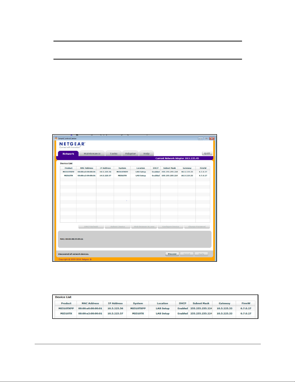
the Discover button.
The Smart Control Center finds your switch.
6. Write down the displayed IP address assigned by the DHCP server.
You need this address later to access the switch directly from a web browser (without
using the Smart Control Center).
7. Select the switch by clicking the row for the switch.
8. Click
Get Started User Manual15
the Web Browser Access button.
Page 16

Smart Managed Pro Switches MS510TX and MS510TXPP
The Smart Control Center launches a browser.
The login window opens.
9. Enter the switch’s password in the Password field.
The default password is password.
The Switch Information page displays. You can now configure the switch.
Access the Switch On-Network Without a DHCP Server
You can use the Smart Control Center (SCC) to set up your switch in a network without a
DHCP server and assign a static IP address to the switch.
If you prefer, you can assign the switch a static IP address even if your network does include
a DHCP server.
The SCC program runs on a Windows-based computer which you can download from
downloadcenter.netgear.com. If you do not use a Windows-based computer, see Access
the Switch Off-Network on page 18.
To assign a static IP address to the switch on-network and access the switch:
1. Connect the switch to a network.
2. Power on the switch by connecting its power cord.
3. Install the Smart Control Center on your computer.
4. Start the Smart Control Center.
5. Click the Discover button.
The Smart Control Center finds your switch.
Get Started User Manual16
Page 17
Smart Managed Pro Switches MS510TX and MS510TXPP
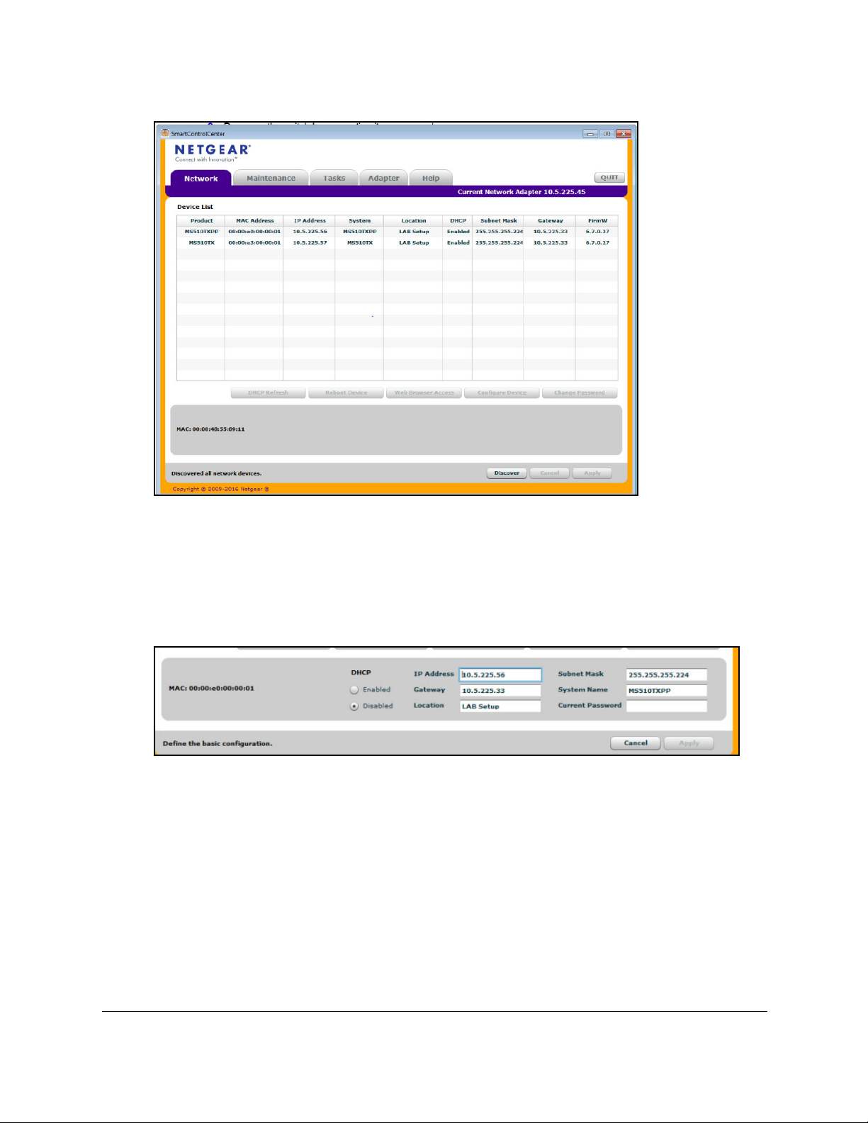
6. Select the switch, and then click the Configure Device button.
The page expands to display additional fields at the bottom.
7. Select
the Disabled radio button.
The DHCP client is disabled.
8. Enter
the static switch IP address, gateway IP address, and subnet mask for the switch.
9. Enter the switch password to continue with the configuration change.
The default password is password.
You must enter the password each time that you use
the Smart Control Center to update the switch settings.
Note: If you change the default password to a custom password (which we
recommend) using the local browser interface and need to use the
Smart Control Center again, you must enter the custom password for
configuration changes to be accepted.
10. Click
the Apply button.
Your settings are saved.
Get Started User Manual17
Page 18

Smart Managed Pro Switches MS510TX and MS510TXPP
11. Click the Discover button.
The Smart Control Center finds your switch with its new IP address.
12. Select the switch by clicking the row for the switch.
13. Click the Web Browser Access button.
The Smart Control Center launches a browser.
The login window opens.
14. Enter the switch’s password in the Password field.
The default password is password.
The Switch Information page displays. You can now configure the switch.
Access the Switch Off-Network
You can connect to the switch directly from a computer and change the settings by using the
local browser interface of the switch. The default IP address of the switch is 192.168.0.239.
The IP address of the computer that you use to access the switch must in the same subnet
as the default IP address of the switch, that is, it must be in the in the 192.168.0.0/24 subnet.
To assign a static IP address to the switch off-network from a directly-connected
computer:
1. Record your computer’s TCP/IP configuration settings, and then configure the computer
with a static IP address.
For example, configure 192.168.0.210 as the IP address and 255.255.255.0 as the
subnet mask.
Note: If you are unsure how to do this, visit
netgear.com/search-support.aspx and search for the following:
How to set a static IP address in Windows
or
Setting a static IP address on your network adapter in Mac OS
2. Plug the switch into a power outlet and then connect your computer to the switch using an
Ethernet cable.
You can connect the Ethernet cable to any Ethernet port on the switch.
3. Open a web browser, and enter http://192.168.0.239.
This is the default address of the switch.
The login window opens.
4. Enter the switch’s password in the Password field.
The default password is password.
The Switch Information page displays. You can now configure the switch.
Get Started User Manual18
Page 19
Smart Managed Pro Switches MS510TX and MS510TXPP
5. After you complete the configuration of the switch, reconfigure the computer that you used
for this process to its original TCP/IP settings.
You can now connect your switch to your network using an Ethernet cable.
Register the Switch
To qualify for product updates and product warranty, we encourage you to register your
product. The first time you log in to the switch, you are given the option of registering with
NETGEAR. Registration confirms that your email alerts work, lowers technical support
resolution time, and ensures that your shipping address accuracy. We would also like to
incorporate your feedback into future product development. We never sell or rent your email
address and you can opt out of communications at any time.
When you log in to the switch, you are prompted to register with
time you can visit the NETGEAR website for registration at
https://my.netgear.com/register/register.aspx.
NETGEAR. However, at any
How to Configure Interface Settings
For some features that allow you to configure interface settings, you can apply the same
settings simultaneously to any of the following:
• A single port
• Multiple ports
• All ports
• A single LAG
• Multiple LAGs
• All LAGs
• Multiple ports and LAGs
• All ports and LAGs
Many of the pages that allow you to configure or view interface settings include links to
display all ports, all LAGs, or all ports and LAGs on the page.
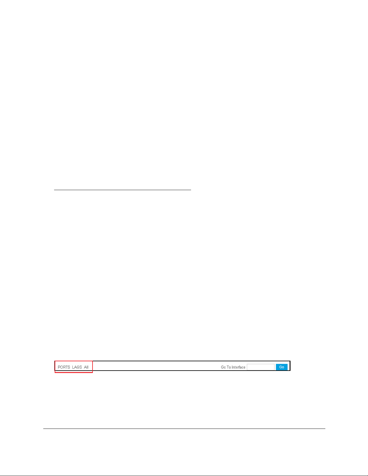
Use these links as follows:
• To display all ports, click the PORTS link.
• T
o display all LAGs, click the LAGS link.
• T
o display all ports and LAGs, click the All link.
Get Started User Manual19
Page 20

Smart Managed Pro Switches MS510TX and MS510TXPP
The procedures in this section describe how to select the ports and LAGs to configure. The
procedures assume that you are already logged in to the switch. If you do not know how to
log in to the switch, see
Access the Switch on page 14.
To configure a single port or LAG:
1. Click the All link to display the all ports and LAGs.
2. Do one of the following:
a. In the Go To Interface field, type the port number and click the Go button.
For example, type g4 for a port or type LAG2 for a LAG. For more information, see
Interface Naming Conventions on page 13.
The check box for the interface is selected, the row for the selected interface is
highlighted, and the interface number displays in the heading row.
b. Select the check box for the port or LAG.
The row for the selected interface is highlighted, and the interface number displays in
the heading row.
3. Configure the desired settings.
4. Click the Apply button.
Your settings are saved.
To configure multiple ports and LAGs:
1. Click the All link to display all ports and LAGs.
2. Select the check box next to each port and LAG to configure.
The row for each selected interface is highlighted.
3. Configure the desired settings.
4. Click the Apply button.
Your settings are saved.
To configure all ports and LAGs:
1. Click the All link to display all ports and LAGs.
2. Select the check box in the heading row.
The check boxes for all ports and LAGs are selected and the rows for all ports and LAGs
are highlighted.
3. Configure the desired settings.
4. Click the Apply button.
Your settings are saved.
Get Started User Manual20
Page 21
Smart Managed Pro Switches MS510TX and MS510TXPP
Local Browser Interface Device View
The Device View displays the ports in the local browser interface displays the ports on the
switch. This graphic provides an alternate way to navigate to configuration and monitoring
options. The graphic also provides information about device ports, current configuration and
status, tables, and feature components.
To use the Device View:
1. Connect
You can use a WiFi or wired connection to connect your computer to the network, or
connect directly to a switch that is of
2. Launch
3. In
4. Enter
5. Select System
the address field of your web browser, enter the IP address of the switch.
If you do not know the IP address of the switch, see
The login window opens.
The default password is password.
The Switch Information page displays.
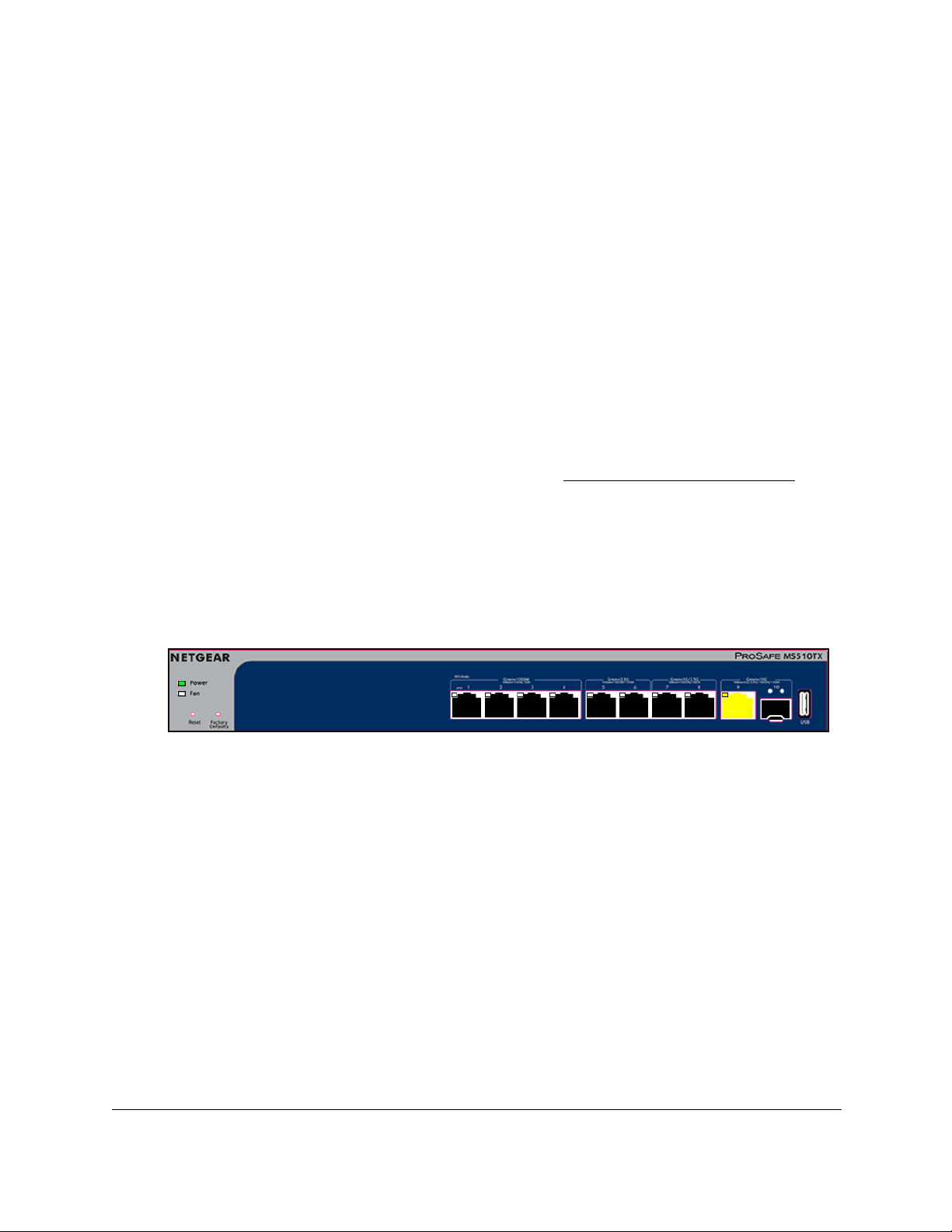
The previous figure shows the Device View page for model MS510TX.
your computer to the same network as the switch.
f-network using an Ethernet cable.
a web browser.
Access the Switch on page 14.
the switch’s password in the Password field.
> Device View.
The system LEDs are located on the left side.
Depending upon the status of the port, the port color in Device V
green, or black (that is, off).
Get Started User Manual21
iew is either yellow,
Page 22

Smart Managed Pro Switches MS510TX and MS510TXPP
The following table describes the LEDs on the Device View page.
Table 3. LEDs on the Device View page
LED Description
Power LED The Power LED is a bicolor LED that serves as an indicator of power and
diagnostic status:
• Solid green. Power is supplied to the switch and the switch is
operating normally.
• Solid yellow. The switch is in the boot-up stage.
• Off. No power is supplied to the switch.
Fan LED The Fan LED indicates the following status:
• Off. Fan is operating normally.
• Solid yellow. A problem occurred with the fan.
PoE MAX LED
(Model MS510TXPP only)
1G Ports 1–4, Left LEDs
Link, speed, and activity
1G Ports 1–4, Right LEDs
PoE status
(Model MS510TXPP only)
2.5G Ports 5 and 6, Left LEDs
Link, speed, and activity
The PoE MAX Power LED indicates the following PoE conditions at
switch (not port) level:
• Off. More than 7W of PoE power is available for another powered
device (PD).
• Solid yellow. Less than 7W of PoE power is available for another
PD.
• Blinking yellow. The PoE Max LED was activate in the previous two
minutes.
The left LEDs for ports 1–4 (g1 to g4) indicate the following status:
• Off. No link is established.
• Solid green. A valid 1 Gbps link is established.
• Blinking green. The port is transmitting or receiving packets at
1
Gbps.
• Solid yellow. A valid 10 Mbps or 100 Mbps link is established.
• Blinking yellow.The port is transmitting or receiving packets at 10
Mbps or 100 Mbps.
The right LEDs for ports 1–4 (g1 to g4) indicate the following status:
• Off. The port is not delivering PoE.
• Solid green. The port is delivering PoE.
• Solid yellow. A PoE fault occurred.
The left LEDs for ports 5 and 6 (mg5 and mg6) indicate the following
status:
• Off. No link is established.
• Solid green. A valid 2.5 Gbps link is established.
• Blinking green. The port is transmitting or receiving packets at 2.5
Gbps.
• Solid yellow. A valid 100 Mbps or 1000 Mbps link is established.
• Blinking yellow. The port is transmitting or receiving packets at 100
Mbps or 1000 Mbps.
Get Started User Manual22
Page 23

Smart Managed Pro Switches MS510TX and MS510TXPP
Table 3. LEDs on the Device View page (continued)
LED Description
2.5G Ports 5 and 6, Right LEDs
PoE status
(Model MS510TXPP only)
5G Ports 7 and 8, Left LEDs
Link, speed, and activity
5G Ports 7 and 8, Right LEDs
PoE status
(Model MS510TXPP only)
10G Port 9, LED
Link, speed, and activity
The right LEDs for ports 5 and 6 (mg5 and mg6) indicate the following
status:
• Off. The port is not delivering PoE.
• Solid green. The port is delivering PoE.
• Solid yellow. A PoE fault occurred.
The left LEDs for ports 7 and 8 (mg7 and mg8) indicate the following
status:
• Off. No link is established.
• Solid green. A valid 2.5 Gbps or 5 Gbps link is established.
• Blinking green. The port is transmitting or receiving packets at 2.5
Gbps or 5 Gbps.
• Solid yellow. A valid 100 Mbps or 1000 Mbps link is established.
• Blinking yellow. The port is transmitting or receiving packets at 100
Mbps or 1000 Mbps.
The right LEDs for ports 7 and 8 (mg7 and mg8) indicate the following
status:
• Off. The port is not delivering PoE.
• Solid green. The port is delivering PoE.
• Solid yellow. A PoE fault occurred.
The LED for port 9 (xmg9) indicates the following status:
• Off. No link is established.
• Solid green. A valid 10 Gbps link is established.
• Blinking green. The port is transmitting or receiving packets at
10
Gbps.
• Solid yellow. A valid 5 Gbps, 2.5 Gbps, 1000 Mbps, or 100 Mbps
link is established.
• Blinking yellow. The port is transmitting or receiving packets at
5
Gbps, 2.5 Gbps, 1000 Mbps, or 100 Mbps
SFP+ Port 10, LEDs
Link, speed, and activity
The LEDs for port 10 (xg10, the SFP+ port) indicate the following status:
• Off. No SFP+ module link is established on the fiber port.
• Left LED solid green. The fiber port established a valid 10 Gbps
link.
• Left LED blinking green. The fiber port is transmitting or receiving
packets at 10 Gbps.
• Right LED solid yellow. The fiber port established a valid 1 Gbps
link.
• Right LED blinking yellow. The fiber port is transmitting or receiving
packets at 1 Gbps
6. To see a menu that displays statistics and configuration options, right-click a port.
Get Started User Manual23
Page 24
Smart Managed Pro Switches MS510TX and MS510TXPP
The previous figure shows the Device View page for model MS510TXPP.
7. T
o display the main menu that contains the same options as the navigation menu at the top
of the page, right-click the graphic without clicking a specific port.
The previous figure shows the Device View page for model MS510TXPP.
Get Started User Manual24
Page 25

2
2Configure System Information
This chapter covers the following topics:
• View and Configure the Switch Management Settings
• Use the Device View
• Configure Power over Ethernet
• Configure SNMP
• Configure LLDP
• Configure DHCP Snooping
• Set Up PoE Timer Schedules
25
Page 26

Smart Managed Pro Switches MS510TX and MS510TXPP
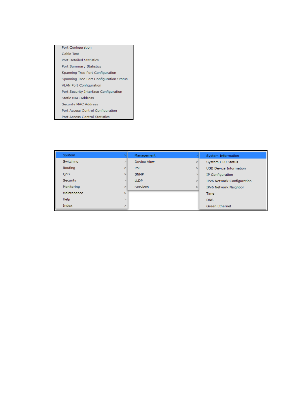
View and Configure the Switch Management Settings
This section describes how to display the switch status and specify some basic switch
information, such as the management interface IP address, system clock settings, and DNS
information. From the System > Management menu, you can access pages that are
described in the following sections:
• View or Define System Information and View Software Versions on page 26
• View the System CPU Status on page 28
• View USB Device Information on page 29
• Configure the IPv4 Address for the Network Interface and Management VLAN on
page 30
• Configure the IPv6 Address for the Network Interface on page 32
• View the IPv6 Network Neighbor on page 33
• Configure the Time Settings on page 34
• Configure DNS Settings on page 44
• Configure Green Ethernet Settings on page 47
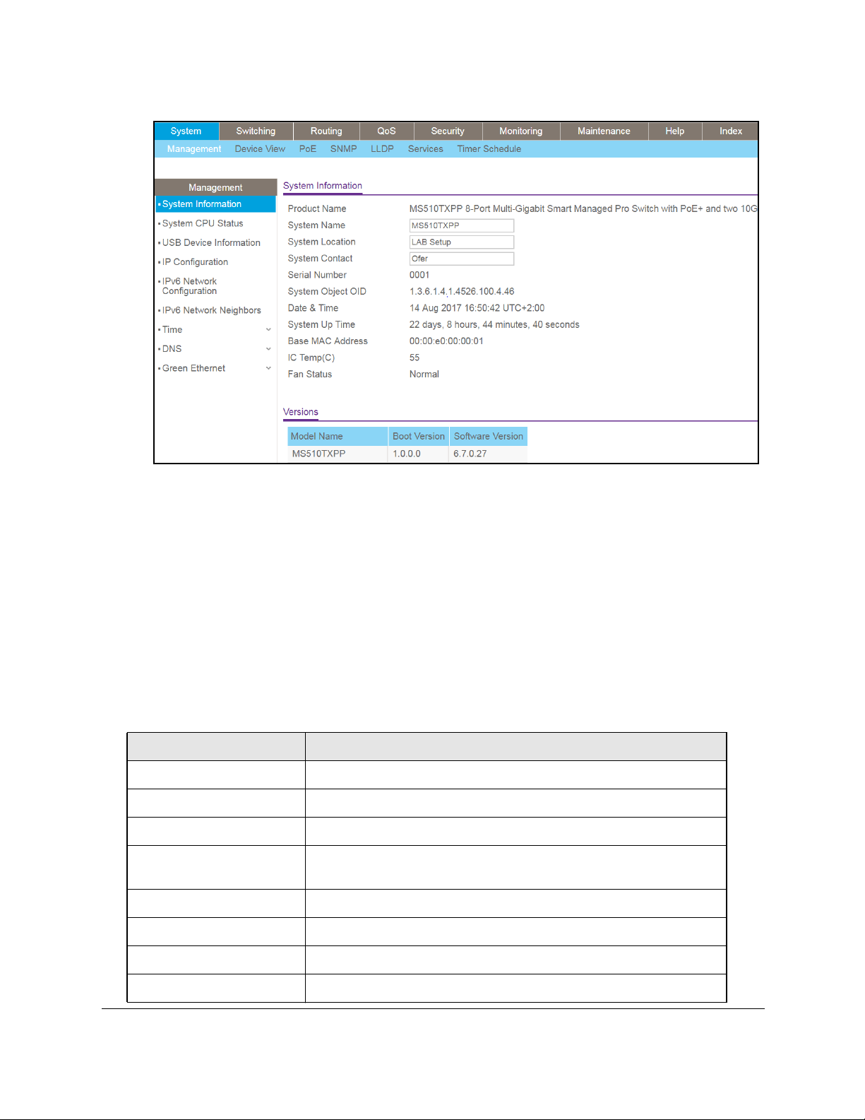
View or Define System Information and View Software Versions
When you log in, the System Information page displays. Use this page to configure and view
general device information such as system name, location, and contact, general system
temperature, temperatures of the fans, and boot and software versions.
To view or define system information and view software versions:
1. Connect your computer to the same network as the switch.
You can use a WiFi or wired connection to connect your computer to the network, or
connect directly to a switch that is off-network using an Ethernet cable.
2. Launch a web browser.
3. In the address field of your web browser, enter the IP address of the switch.
If you do not know the IP address of the switch, see Access the Switch on page 14.
The login window opens.
4. Enter the switch’s password in the Password field.
The default password is password.
The System Information page displays.
Configure System Information User Manual26
Page 27
Smart Managed Pro Switches MS510TX and MS510TXPP
5. Define the following fields:
• System Name. Enter the name to identify this switch.
You can use up to 255
alphanumeric characters. The default is blank.
• System Location. Enter the location of this switch.
You can use up to 255
alphanumeric characters. The default is blank.
• System Contact. Enter the contact person for this switch.
You can use up to 255
alphanumeric characters. The default is blank.
6. Click
the Apply button.
Your settings are saved.
The following table describes the status information that the System Information page
displays.
Field Description
Serial Number The serial number of the switch.
System Object ID The base object ID for the switch’s enterprise MIB.
Date & Time The current date and time.
System Up Time The number of days, hours, minutes, and seconds since the last system
restart.
Base MAC Address Universally assigned network address.
IC Temp(C) Integrated circuit temperature in Celsius values.
Fan Status The status of fan operations.
Model Name The model name of the switch.
Configure System Information User Manual27
Page 28

Smart Managed Pro Switches MS510TX and MS510TXPP
Field Description
Boot Version The boot code version of the switch.
Software Version The software version of the switch.
View the System CPU Status
Use the System CPU Status page to monitor the CPU, memory resources, and utilization
patterns across various intervals to assess the performance of the switch.
To configure and view the system CPU status and utilization:
1. Connect your computer to the same network as the switch.
You can use a WiFi or wired connection to connect your computer to the network, or
connect directly to a switch that is off-network using an Ethernet cable.
2. Launch a web browser.
3. In the address field of your web browser, enter the IP address of the switch.
If you do not know the IP address of the switch, see Access the Switch on page 14.
The login window opens.
4. Enter the switch’s password in the Password field.
The default password is password.
The System Information page displays.
5. Select System > Management > System CPU Status.
The CPU Memory Status page displays.
The page shows the total system memory and the available memory in MB.
6. Enable the switch to calculate the CPU utilization:
• CPU Utilization. Select the Disable or Enable radio button. By default, the Enable
radio button is selected.
• Refresh Rate. Select a radio button number to specify the number of seconds at
which the CPU utilization is computed. By default, the No radio button is selected.
The CPU Input Rate field shows the number of frames forwarded to the CPU per second.
The CPU utilization rate is displayed in a graph. The Y axis represents the CPU utilization
in percentage. The X axis represents the number of elapsed seconds and is correlated to
the selected refresh rate.
Configure System Information User Manual28
Page 29

Smart Managed Pro Switches MS510TX and MS510TXPP
View USB Device Information
Use the USB Device Information page to display the USB device status, memory statistics,
and directory details.
The limitations for the USB device supported on the switch are as follows:
• The USB disk must comply with the USB 2.0 standard.
• The USB disk must be file type F
To display the USB device information:
AT32. File type NTFS is not supported.
1. Connect
your computer to the same network as the switch.
You can use a WiFi or wired connection to connect your computer to the network, or
connect directly to a switch that is of
f-network using an Ethernet cable.
2. Launch a web browser.
3. In
the address field of your web browser, enter the IP address of the switch.
If you do not know the IP address of the switch, see
Access the Switch on page 14.
The login window opens.
4. Enter
the switch’s password in the Password field.
The default password is password.
The System Information page displays.
5. Select System
> Management > USB Device Information.
The USB Memory Statistics page displays.
6. T
o refresh the page, click the Refresh button.
The following table describes the USB Memory Statistics information.
Table 4. USB Memory Statistics information
Field Description
Total Size The USB flash device storage size in bytes.
Bytes Used The size of memory used on the USB flash device.
Bytes Free The size of memory free on the USB flash device.
Configure System Information User Manual29
Page 30

Smart Managed Pro Switches MS510TX and MS510TXPP
The following table describes the USB Directory Details information.
Table 5. USB Directory Details information
Field Description
File Name The name of the file stored in the USB flash drive.
Type The type of file, which can be one of the following:
• Folder.
Click the folder name to view the contents of the subfolder.
• File.
• Other.
- Current path.
- Parent folder path.
File Size The size, in bytes, of the file stored in the USB flash drive.
Modification Time The last modification time of the file stored in the USB flash drive.
A subfolder within the file.
A file.
A path, which can be one of the following:
The full path for the folder that is being displayed.
The path for the parent folder of the folder
that is being displayed. You can click the entry and open the
parent folder.
Configure the IPv4 Address for the Network Interface and Management VLAN
You can configure network information for the network interface, which is the logical interface
used for in-band connectivity with the switch through any of the switch’s ports. You also use
the IPv4 address of the network interface to connect to the switch through the local browser
interface. The configuration parameters that is associated with the switch’s network interface
do not affect the configuration of the ports through which traffic is switched.
To configure the IPv4 address for the network interface and the management VLAN:
1. Connect
You can use a WiFi or wired connection to connect your computer to the network, or
connect directly to a switch that is of
2. Launch a web browser.
3. In
the address field of your web browser, enter the IP address of the switch.
If you do not know the IP address of the switch, see
The login window opens.
4. Enter
The default password is password.
your computer to the same network as the switch.
f-network using an Ethernet cable.
Access the Switch on page 14.
the switch’s password in the Password field.
The System Information page displays.
5. Select System > Management > IP Configuration.
The IP Configuration page displays.
Configure System Information User Manual30
Page 31

Smart Managed Pro Switches MS510TX and MS510TXPP
6. Select a radio button to determine how to configure the network information for the switch
management interface:
• Static IP Address. Specifies that the IP address, subnet mask, and default gateway
must be manually configured. Enter this information in the fields below this radio
button.
• Dynamic IP Address (DHCP). Specifies that the switch must obtain the IP address
through a DHCP server.
7. If you select the Static IP Address radio button, configure the following network information:
• IP Address. The IP address of the network interface. Each part of the IP address
must start with a number other than zero. For example, IP addresses 001.100.192.6
and 192.001.10.3 are not valid. The factory default IP address is 192.168.0.239.
• Subnet Mask. The IP subnet mask for the interface. The factory default subnet mask
is 255.255.255.0.
• Default Gateway. The default gateway for the IP interface. The factory default
gateway address is 192.168.0.254.
8. From the Management VLAN ID menu, select the VLAN ID for the management VLAN.
The management VLAN is used to establish an IP connection to the switch from a
computer that is connected to a port in the same VLAN. If not specified, the active
management VLAN ID is 1 (default), which allows an IP connection to be established
through any port.
When the management VLAN is set to a different value, an IP connection can be made
only through a port that is part of the management VLAN. Also, the port VLAN ID (PVID)
of the port to be connected in that management VLAN must be the same as the
management VLAN ID.
Note: Make sure that the VLAN that must be the management VLAN exists.
Also make sure that the PVID of at least one port in the VLAN is the
same as the management VLAN ID. For information about creating
VLANs and configuring the PVID for a port, see
Configure VLANs on
page 96.
The following requirements apply to the management VLAN:
• Only one management VLAN can be active at a time.
• When a new management VLAN is configured, connectivity through the existing
management VLAN is lost.
• The management station must be reconnected to the port in the new management
VLAN.
9. Click the Apply button.
Your settings are saved.
Configure System Information User Manual31
Page 32

Smart Managed Pro Switches MS510TX and MS510TXPP
Configure the IPv6 Address for the Network Interface
You can configure the IPv6 address for the network interface, which is the logical interface
used for in-band connectivity with the switch through any of the switch’s front-panel ports.
You also use the IPv6 address of the network interface to connect to the switch through the
local browser interface. The configuration parameters that is associated with the switch’s
network interface do not affect the configuration of the ports through which traffic is switched.
To access the switch over an IPv6 network, you must initially configure the switch with IPv6
information (IPv6 prefix, prefix length, and default gateway). IPv6 can be configured using
any of the following options:
• IPv6 autoconfiguration
• DHCPv6
When in-band connectivity is established, IPv6 information can be changed using
SNMP-based management or web-based management.
To configure the IPv6 address for the network interface:
1. Connect your computer to the same network as the switch.
You can use a WiFi or wired connection to connect your computer to the network, or
connect directly to a switch that is off-network using an Ethernet cable.
2. Launch a web browser.
3. In the address field of your web browser, enter the IP address of the switch.
If you do not know the IP address of the switch, see Access the Switch on page 14.
The login window opens.
4. Enter the switch’s password in the Password field.
The default password is password.
The System Information page displays.
5. Select System > Management > IPv6 Network Configuration.
The IPv6 Network Global Configuration page displays.
6. Ensure that the Admin Mode Enable radio button is selected.
7. Select IPv6 Address Auto Configuration Mode Enable radio button to enable the network
interface to acquire an IPv6 address through IPv6 Neighbor Discovery Protocol (NDP) and
through the use of router advertisement messages.
When this mode is disabled, the network interface does not use the native IPv6 address
autoconfiguration features to acquire an IPv6 address.
8. In the Current Network Configuration Protocol field define the IPv6 network interface to
receive an IPv6 address from a DHCP server. The default value is None.
9. If the above field is set to DHCPv6 Protocol, the DHCPv6 Client DUID field (read only)
displays the DHCPv6 client DUID
Configure System Information User Manual32
Page 33

Smart Managed Pro Switches MS510TX and MS510TXPP
10. In the IPv6 Gateway field, specify the default gateway for the IPv6 network interface.
The gateway address is in IPv6 global or link-local address format.
11. To configure one or more static IPv6 addresses for the management interface, do the
following:
a. In the IPv6 Prefix/Prefix Length field, specify the static IPv6 prefix and prefix to the
IPv6 network interface.
The address is in the global address format.
b. In the EUI64 menu, select True to enable the Extended Universal Identifier (EUI)
flag for IPv6 address, or select False to omit the EUI flag.
c. Click the Add button.
12. Click the Apply button.
Your settings are saved.
View the IPv6 Network Neighbor
Use the IPv6 Network Neighbor page to view information about the IPv6 neighbors that the
switch discovers through the network interface by using the Neighbor Discovery Protocol
(NDP).
To view the IPv6 neighbor table:
1. Connect your computer to the same network as the switch.
You can use a WiFi or wired connection to connect your computer to the network, or
connect directly to a switch that is off-network using an Ethernet cable.
2. Launch a web browser.
3. In the address field of your web browser, enter the IP address of the switch.
If you do not know the IP address of the switch, see Access the Switch on page 14.
The login window opens.
4. Enter the switch’s password in the Password field.
The default password is password.
The System Information page displays.
5. Select System > Management > IPv6 Network Neighbor.
The IPv6 Network Interface Neighbor Table page displays.
Configure System Information User Manual33
Page 34

Smart Managed Pro Switches MS510TX and MS510TXPP
The following table describes the information that the IPv6 Network Interface Neighbor Table
displays about each IPv6 neighbor that the switch discovered.
Table 6. IPv6 network interface neighbor table information
Field Description
IPv6 Address The IPv6 address of a neighbor switch visible to the network interface.
MAC Address The MAC address of a neighbor switch.
isRtr • True.
• False.
Neighbor State The state of the neighboring switch:
• Reach.
• Stale.
• Delay.
• Probe.
Last Updated The last time that the neighbor was updated.
The neighbor machine is a router.
The neighbor machine is not a router.
No more than ReachableTime milliseconds elapsed since the switch received
confirmation that the forward path to the neighbor was functioning properly. In the
Reach state, the device takes no special action when packets are sent.
More than ReachableTime milliseconds elapsed since the switch received
confirmation that the forward path was functioning properly. In the Stale state, the
device takes no action until a packet is sent.
More than ReachableTime milliseconds elapsed since the switch received
confirmation that the forward path was functioning properly. A packet was sent within
the last DELAY_FIRST_PROBE_TIME seconds. If no confirmation is received within
DELAY_FIRST_PROBE_TIME seconds of entering the Delay state, the device sends
a neighbor solicitation message and changes the state to Probe.
The switch actively seeks confirmation by repeatedly sending neighbor
solicitation messages each RetransTimer milliseconds until a confirmation is
received.
Configure the Time Settings
The switch supports the Simple Network Time Protocol (SNTP). As its name suggests, it is a
less complicated version of Network Time Protocol, which is a system for synchronizing the
clocks of networked computer systems, primarily when data transfer is handled through the
Internet. You can also set the system time manually.
Configure the Time Setting Manually
Use the Time Configuration page to view and adjust date and time settings.
To manually configure the time setting:
1. Connect
You can use a WiFi or wired connection to connect your computer to the network, or
connect directly to a switch that is of
2. Launch a web browser.
3. In
the address field of your web browser, enter the IP address of the switch.
Configure System Information User Manual34
your computer to the same network as the switch.
f-network using an Ethernet cable.
Page 35

Smart Managed Pro Switches MS510TX and MS510TXPP
If you do not know the IP address of the switch, see Access the Switch on page 14.
The login window opens.
4. Enter the switch’s password in the Password field.
The default password is password.
The System Information page displays.
5. Select System > Management > Time > SNTP Global Configuration.
The Time Configuration page displays.
6. Select the Clock Source Local radio button.
7. In the Date field, specify the current date in months, days, and years (DD-MMM-YYYY).
8. In the Time field, specify the current time in hours, minutes, and seconds (HH:MM:SS).
Note: If you do not enter a date and time, the switch calculates the date and
time using the CPU’s clock cycle.
9. Click the Apply button.
Your settings are saved.
Configure an SNTP Server
SNTP assures accurate network device clock time synchronization up to the millisecond.
Time synchronization is performed by a network SNTP server. The switch operates only as
an SNTP client and cannot provide time services to other systems.
Time sources are established by strata. Strata define the accuracy of the reference clock.
The higher the stratum (where zero is the highest), the more accurate the clock. The device
receives time from Stratum 1 and above since it is itself a Stratum 2 device.
The following is an example of strata:
• Stratum 0. A real-time clock is used as the time source, for example, a GPS system.
• Stratum 1. A server that is directly linked to a Stratum 0 time source is used. Stratum 1
time servers provide primary network time standards.
• Stratum 2. The time source is distanced from the Stratum 1 server over a network path.
For example, a Stratum 2 server receives the time over a network link, through NTP, from
a Stratum 1 server.
Information received from SNTP servers is evaluated based on the time level and server
type.
SNTP time definitions are assessed and determined by the following time levels:
•T1. Time that the original request was sent by the client.
•T2. Time that the original request was received by the server.
•T3. Time that the server sent a reply.
•T4. Time that the client received the server's reply.
Configure System Information User Manual35
Page 36

Smart Managed Pro Switches MS510TX and MS510TXPP
The device can poll unicast server types for the server time.
Polling for unicast information is used for polling a server for which the IP address is known.
SNTP servers that were configured on the device are the only ones that are polled for
synchronization information. T1 through T4 are used to determine server time. This is the
preferred method for synchronizing device time because it is the most secure method. If this
method is selected, SNTP information is accepted only from SNTP servers defined on the
device using the SNTP Server Configuration page.
The device retrieves synchronization information, either by actively requesting information or
at every poll interval.
You can view and modify information for adding and modifying Simple Network Time Protocol
SNTP servers.
Add an SNTP Server
To add an SNTP server:
1. Connect your computer to the same network as the switch.
You can use a WiFi or wired connection to connect your computer to the network, or
connect directly to a switch that is off-network using an Ethernet cable.
2. Launch a web browser.
3. In the address field of your web browser, enter the IP address of the switch.
If you do not know the IP address of the switch, see Access the Switch on page 14.
The login window opens.
4. Enter the switch’s password in the Password field.
The default password is password.
The System Information page displays.
5. Select System > Management > Time > SNTP Server Configuration.
The SNTP Server Configuration page displays. The page also displays the SNTP Server
Status section.
6. From the Server Type menu, select the type of SNTP address to enter in the Address field.
The address can be either an IP address (IPv4, IPv6) or a host name (DNS). The default
value is IPv4.
7. In the Address field, specify the IP address or the host name of the SNTP server.
Unicast SNTP requests are sent to this address. If this address is a DNS host name, then
that host name is resolved into an IP address each time an SNTP request is sent to it.
8. If the UDP port on the SNTP server to which SNTP requests are sent is not the standard
port (123), specify the port number in the Port field.
The valid range is 1 to 65535. The default value is 123.
Configure System Information User Manual36
Page 37

Smart Managed Pro Switches MS510TX and MS510TXPP
9. Click the Add button.
The SNTP server entry is added.
10. Repeat
the previous steps to add additional SNTP servers.
You can configure up to eight SNTP servers.
The SNTP Server Status table displays status information about the SNTP servers
configured on your switch.
The following table describes the SNTP Server Global Status
information.
Table 7. SNTP Server Status information
Field Description
Address All the existing server addresses. If no server configuration exists, a message stating
that no SNTP server exists displays on the page.
Last Update Time The local date and time (UTC) that the response from this server was used to update
the system clock.
Change the Settings for an Existing SNTP Server
To change the settings for an existing SNTP server:
1. Connect
your computer to the same network as the switch.
You can use a WiFi or wired connection to connect your computer to the network, or
connect directly to a switch that is of
f-network using an Ethernet cable.
2. Launch a web browser.
3. In
the address field of your web browser, enter the IP address of the switch.
If you do not know the IP address of the switch, see
The login window opens.
4. Enter
the switch’s password in the Password field.
The default password is password.
The System Information page displays.
5. Select System
> Management > Time > SNTP Server Configuration.
The SNTP Server Configuration page displays.
6. Select
7. Specify
8. Click
the check box for the configured server.
new values in the available fields.
the Apply button.
Your settings are saved.
Access the Switch on page 14.
Configure System Information User Manual37
Page 38

Smart Managed Pro Switches MS510TX and MS510TXPP
Remove an SNTP Server
To remove an SNTP server:
1. Connect your computer to the same network as the switch.
You can use a WiFi or wired connection to connect your computer to the network, or
connect directly to a switch that is off-network using an Ethernet cable.
2. Launch a web browser.
3. In the address field of your web browser, enter the IP address of the switch.
If you do not know the IP address of the switch, see Access the Switch on page 14.
The login window opens.
4. Enter the switch’s password in the Password field.
The default password is password.
The System Information page displays.
5. Select System > Management > Time > SNTP Server Configuration.
The SNTP Server Configuration page displays.
6. Select the check box for the configured server to remove.
7. Click the Delete button.
The entry is removed, and the device is updated.
Enable SNTP and Configure the Time Zone Offset
You must first configure an SNTP server (see Configure an SNTP Server on page 35) before
you can enable SNTP.
To enable SNTP settings and configure the time zone offset:
1. Connect your computer to the same network as the switch.
You can use a WiFi or wired connection to connect your computer to the network, or
connect directly to a switch that is off-network using an Ethernet cable.
2. Launch a web browser.
3. In the address field of your web browser, enter the IP address of the switch.
If you do not know the IP address of the switch, see Access the Switch on page 14.
The login window opens.
4. Enter the switch’s password in the Password field.
The default password is password.
The System Information page displays.
5. Select System > Management > Time > SNTP Global Configuration.
Configure System Information User Manual38
Page 39

Smart Managed Pro Switches MS510TX and MS510TXPP
The Time Configuration page displays.
6. Select the Clock Source SNTP radio button.
The Date and Time fields are disabled because the switch receives the date and time
from the network.
7. From the Time Zone Offset menu, select the number of hours that the time zone in which
the switch is located differs from the Coordinated Universal Time (UTC).
The time zone can affect the display of the current system time. The default value is UTC
0:00.
Note: When you use SNTP/NTP time servers to update the switch’s clock,
the time data received from the server is based on the UTC 0:00, which
is the same as Greenwich Mean Time (GMT). This might not be the
time zone in which the switch is located.
8. Click the Apply button.
Your settings are saved.
9. To refresh the page, click the Refresh button.
View SNTP Global Status
You can view global SNTP status information.
To view SNTP global status:
1. Connect your computer to the same network as the switch.
You can use a WiFi or wired connection to connect your computer to the network, or
connect directly to a switch that is off-network using an Ethernet cable.
2. Launch a web browser.
3. In the address field of your web browser, enter the IP address of the switch.
If you do not know the IP address of the switch, see Access the Switch on page 14.
The login window opens.
4. Enter the switch’s password in the Password field.
The default password is password.
The System Information page displays.
5. Select System > Management > Time > SNTP Global Status.
The SNTP Global Status page displays.
6. Click the Refresh button to update the page with the latest information about the switch.
Configure System Information User Manual39
Page 40

Smart Managed Pro Switches MS510TX and MS510TXPP
The following table displays the nonconfigurable SNTP Global Status information.
Table 8. SNTP Global Status information
Field Description
Version The SNTP version that the client supports.
Supported mode The SNTP modes that the client supports. Multiple modes can be supported
a client.
Last Update Time The local date and time (UTC) that the SNTP client last updated the system
clock.
Server IP Address The IP address of the server for the last received valid packet. If no message
was received from any server
Address Type The address type of the SNTP server address for the last received valid
packet.
Server Stratum The claimed stratum of the server for the last received valid packet.
Server mode The mode of the server for the last received valid packet.
Unicast Server Max Entries The maximum number of unicast server entries that can be configured on this
client.
Unicast Server Current Entries The number of current valid unicast server entries configured for this client.
, an empty string is shown.
by
Configure Daylight Saving Time Settings
Use the Daylight Saving Time Configuration page to configure settings for daylight saving
time, which is also known as summer time. Used in some countries around the world,
daylight saving time is the practice of temporarily advancing clocks during the summer
months. Typically clocks are adjusted forward one or more hours near the start of spring and
are adjusted backward in autumn.
To configure the daylight saving time settings:
1. Connect
your computer to the same network as the switch.
You can use a WiFi or wired connection to connect your computer to the network, or
connect directly to a switch that is of
f-network using an Ethernet cable.
2. Launch a web browser.
3. In
the address field of your web browser, enter the IP address of the switch.
If you do not know the IP address of the switch, see
The login window opens.
4. Enter
the switch’s password in the Password field.
The default password is password.
The System Information page displays.
5. Select System
Configure System Information User Manual40
> Management > Time > Daylight Saving Configuration.
Access the Switch on page 14.
Page 41

Smart Managed Pro Switches MS510TX and MS510TXPP
6. Select a Daylight Saving (DST) radio button:
• Disable. Disable daylight saving time.
• Recurring. Daylight saving time occurs at the same time every year. The start and
end times and dates for the time shift must be manually configured.
• Recurring EU.
The system clock uses the standard recurring daylight saving time
settings used in countries in the European Union. When this option is selected, the
rest of the applicable fields on the page are automatically populated and cannot be
edited.
• Recurring USA.
The system clock uses the standard recurring daylight saving time
settings used in the United States. When this option is selected, the rest of the
applicable fields on the page are automatically populated and cannot be edited.
• Non Recurring.
Daylight saving time settings are in effect only between the start date
and end date of the specified year. When this option is selected, the daylight saving
time settings do not repeat on an annual basis.
If you select any radio button other than the Disable radio button (which is the default
selection), the page adjusts to display additional fields.
Configure System Information User Manual41
Page 42

Smart Managed Pro Switches MS510TX and MS510TXPP
7. Configure how the daylight saving settings recur as described in the following table.
Field Description
Begins At
Note: These
the Recurring EU radio button or the
Recurring USA radio button.
Ends At
Note: These
the Recurring EU radio button or the
Recurring USA radio button.
fields do not apply if you select
fields do not apply if you select
If you select the Recurring radio button, specify the start
date and time of daylight saving time in the following fields:
• Week.
• Day.
• Month.
• Hours.
• Minutes.
If you select the Non Recurring radio button, specify the
start date and time of daylight saving in the following fields:
• Year.
• Date.
• Month.
• Hours.
• Minutes.
If you select the Recurring radio button, specify the end
date and time of daylight saving in the following fields:
• Week.
• Day.
• Month.
• Hours.
• Minutes.
If you select the Non Recurring radio button, specify the
end date and time of daylight saving in the following fields:
• Year.
• Date.
• Month.
• Hours.
• Minutes.
Configure the start week.
Configure the start day.
Configure the start month.
Configure the start hour.
Configure the start minute.
Configure the start year.
Configure the start date.
Configure the start month.
Configure the start hour.
Configure the start minute.
Configure the end week.
Configure the end day.
Configure the end month.
Configure the end hour.
Configure the end minute.
Configure the end year.
Configure the end date.
Configure the end month.
Configure the end hour.
Configure the end minute.
Offset
Note: These
the Recurring radio button or the Non
Recurring radio button.
Zone
Note: These
the Recurring radio button or the Non
Recurring radio button.
fields do not apply if you select
fields do not apply if you select
If you select the Recurring EU radio button or the
Recurring USA radio button, you must specify the recurring
offset of daylight saving time in minutes. This is the offset in
relation to regular time, that is, when daylight saving time is
not in effect. The default setting (offset) is 60 minutes.
If you select the Recurring EU radio button or the
Recurring USA radio button, you can specify the acronym
associated with the time zone in which daylight saving is in
ef
time zone acronyms.
8. Click the Apply button.
Your settings are saved.
Configure System Information User Manual42
fect. This field is not validated against any official list of
Page 43

Smart Managed Pro Switches MS510TX and MS510TXPP
View the DayLight Saving Time Status
You can view the status of daylight saving time (DST), including information about the
daylight saving time settings and whether the time offset for daylight saving time is in effect.
To view the daylight saving time status:
1. Connect
your computer to the same network as the switch.
You can use a WiFi or wired connection to connect your computer to the network, or
connect directly to a switch that is of
f-network using an Ethernet cable.
2. Launch a web browser.
3. In
the address field of your web browser, enter the IP address of the switch.
If you do not know the IP address of the switch, see
Access the Switch on page 14.
The login window opens.
4. Enter
the switch’s password in the Password field.
The default password is password.
The System Information page displays.
5. Select System
> Management > Time > DayLight Saving Configuration.
The DayLight Saving (DST) Status page displays.
6. T
o refresh the page, click the Refresh button.
The following table displays the nonconfigurable daylight saving status information.
Table 9. Daylight Saving (DST) Status information
Field Description
DayLight Saving (DST) The Daylight Saving value, which is one of the following:
• Disable
• Recurring
• Recurring
• Recurring
• Non
Begins At Displays when the daylight saving time begins. This field is not
displayed when daylight saving time is disabled.
Ends At Displays when the daylight saving time ends. This field is not displayed
when daylight saving time is disabled.
Offset (in Minutes) The offset value in minutes.This field is not displayed when daylight
saving time is disabled.
Zone The zone acronym, if any was specified. This field is not displayed
when daylight saving time is disabled.
Daylight Saving (DST) in Effect Displays whether daylight saving time is in effect.
Configure System Information User Manual43
EU
USA
Recurring
Page 44

Smart Managed Pro Switches MS510TX and MS510TXPP
Configure DNS Settings
Use these pages to configure information about DNS servers that the network uses and how
the switch operates as a DNS client.
Configure Global DNS Settings
Use the DNS Configuration page to configure global DNS settings and DNS server
information.
To configure the global DNS settings:
1. Connect your computer to the same network as the switch.
You can use a WiFi or wired connection to connect your computer to the network, or
connect directly to a switch that is off-network using an Ethernet cable.
2. Launch a web browser.
3. In the address field of your web browser, enter the IP address of the switch.
If you do not know the IP address of the switch, see Access the Switch on page 14.
The login window opens.
4. Enter the switch’s password in the Password field.
The default password is password.
The System Information page displays.
5. Select System > Management > DNS > DNS Configuration.
The DNS Configuration page displays.
6. Select the Disable or Enable radio button to specify whether to disable or enable the
administrative status of the DNS client:
• Enable. Allow the switch to send DNS queries to a DNS server to resolve a DNS
domain name. The DNS is enabled by default.
• Disable. Prevent the switch from sending DNS queries.
7. In the DNS Default Name field, enter the default DNS domain name to include in DNS
queries.
When the system is performing a lookup on an unqualified host name, this field is
provides the domain name (for example, if default domain name is netgear.com and the
user enters test, then test is changed to test.netgear.com to resolve the name). The name
must not be longer than 158 characters.
8. To add a DSN server, do the following:
a. In the DNS Server field in the DNS Server Configuration table, specify the IPv4
address to which the switch sends DNS queries.
b. Click the Add button.
Configure System Information User Manual44
Page 45

Smart Managed Pro Switches MS510TX and MS510TXPP
The server is added to the list. You can specify up to eight DNS servers. The Preference
field displays the server preference order. The preference is set in the order in which
preferences were entered.
o remove a DNS server from the list, do the following:
9. T
a. Select the check box for the server
b. Click
10. Click
the Delete button.
the Apply button.
.
Your settings are saved.
11. T
o refresh the page, click the Refresh button.
The following table displays DNS Server Configuration information.
Table 10. DNS Server Configuration information
Field Description
ID The identification of the DNS Server.
Preference Shows the preference of the DNS server. The preferences are
determined by the order in which they were entered.
Configure and View Host Name-to-IP Address Information
Use this page to manually map host names to IP addresses or to view dynamic host
mappings.
Add a Static Entry to the Dynamic Host Mapping Table
To add a static entry to the local dynamic host mapping table:
1. Connect
You can use a WiFi or wired connection to connect your computer to the network, or
connect directly to a switch that is of
2. Launch a web browser.
3. In
the address field of your web browser, enter the IP address of the switch.
If you do not know the IP address of the switch, see
The login window opens.
4. Enter
The default password is password.
The System Information page displays.
5. Select System
your computer to the same network as the switch.
f-network using an Ethernet cable.
Access the Switch on page 14.
the switch’s password in the Password field.
> Management > DNS > Host Configuration.
The DNS Host Configuration page displays.
6. In
Configure System Information User Manual45
the Host Name (1 to 158 characters) field, specify the static host name to add.
Page 46

Smart Managed Pro Switches MS510TX and MS510TXPP
Its length cannot exceed 158 characters and it is a required field.
7. In the IPv4/IPv6 Address field, enter the IP address to associate with the host name.
8. Click the Add button.
The entry displays in the list on the page.
Remove an Entry From the Dynamic Host Mapping Table
To remove an entry from the dynamic host mapping table:
1. Connect your computer to the same network as the switch.
You can use a WiFi or wired connection to connect your computer to the network, or
connect directly to a switch that is off-network using an Ethernet cable.
2. Launch a web browser.
3. In the address field of your web browser, enter the IP address of the switch.
If you do not know the IP address of the switch, see Access the Switch on page 14.
The login window opens.
4. Enter the switch’s password in the Password field.
The default password is password.
The System Information page displays.
5. Select System > Management > DNS > Host Configuration.
The DNS Host Configuration page displays.
6. Select the check box for the entry to remove.
7. Click the Delete button.
The entry is removed.
Change the Host Name or IP Address in an Entry of the Dynamic Host Mapping Table and
View All Entries
To change the host name or IP address in an entry of the dynamic host mapping table
and view all entries:
1. Connect your computer to the same network as the switch.
You can use a WiFi or wired connection to connect your computer to the network, or
connect directly to a switch that is off-network using an Ethernet cable.
2. Launch a web browser.
3. In the address field of your web browser, enter the IP address of the switch.
If you do not know the IP address of the switch, see Access the Switch on page 14.
The login window opens.
4. Enter the switch’s password in the Password field.
Configure System Information User Manual46
Page 47

Smart Managed Pro Switches MS510TX and MS510TXPP
The default password is password.
The System Information page displays.
5. Select System
> Management > DNS > Host Configuration.
The DNS Host Configuration page display.
6. Select
7. Enter
8. Click
the check box for the entry to update.
the new information in the appropriate field.
the Apply button.
Your settings are saved.
9. T
o clear all the dynamic host name entries from the list, click the Clear button.
The Dynamic Host Mapping table shows host name-to-IP address entries that the switch
learned.
Table 11. Dynamic Host Mapping information
Field Description
Host The host name that you assign to the specified IP address.
Type The type of the dynamic entry.
IPv4/IPv6 Address The IP address associated with the host name.
The following table describes the dynamic host fields.
Configure Green Ethernet Settings
Use this page to globally configure Green Ethernet features. Using the Green Ethernet
Configuration features allows for power consumption savings.
To configure the Green Ethernet settings:
1. Connect
your computer to the same network as the switch.
You can use a WiFi or wired connection to connect your computer to the network, or
connect directly to a switch that is of
f-network using an Ethernet cable.
2. Launch a web browser.
3. In
the address field of your web browser, enter the IP address of the switch.
If you do not know the IP address of the switch, see
Access the Switch on page 14.
The login window opens.
4. Enter
the switch’s password in the Password field.
The default password is password.
The System Information page displays.
5. Select System
> Management > Green Ethernet > Green Ethernet Configuration.
The Green Ethernet Configuration page displays.
Configure System Information User Manual47
Page 48

Smart Managed Pro Switches MS510TX and MS510TXPP
Auto Power Down mode is enabled globally, but you can disable it on a per-port basis for
ports g1–g4 (see
cannot disable it for other ports. If Auto Power Down mode is enabled on a port and the
port link goes down, the physical layer (PHY) automatically shuts down for a short period
and wakes up to check link pulses. This mode reduces power consumption on a port if no
link partner is present.
Short Cable mode is enabled globally, but you can disable it on a per-port basis for ports
g1–g4 (see
disable it for other ports. If Short Cable mode is enabled on a port, and the cable length is
too short, the PHY enters low-power mode.
6. Select the EEE Mode Disable or Enable radio button.
Energy Efficient Ethernet (EEE) combines the MAC with a family of physical layers that
support operation in a low power mode. It is defined by IEEE 802.3az Energy Efficient
Task Force. Lower power mode enables both the send and receive sides of the link to
disable some functionality for power savings when lightly loaded. Transition to low power
mode does not change the link status. Frames in transit are not dropped or corrupted in
transition to and from low power mode. Transition time is transparent to upper layer
protocols and applications.
Manage and View the PoE Port Configuration on page 57). You
Manage and View the PoE Port Configuration on page 57). You cannot
7. Click the Apply button.
Your settings are saved.
Configure Green Ethernet Interface Settings
Use this page to configure per-port Green Ethernet settings.
To configure the Green Ethernet interface settings:
1. Connect your computer to the same network as the switch.
You can use a WiFi or wired connection to connect your computer to the network, or
connect directly to a switch that is off-network using an Ethernet cable.
2. Launch a web browser.
3. In the address field of your web browser, enter the IP address of the switch.
If you do not know the IP address of the switch, see Access the Switch on page 14.
The login window opens.
4. Enter the switch’s password in the Password field.
The default password is password.
The System Information page displays.
5. Select System > Management > Green Ethernet > Green Ethernet Interface
Configuration.
The Green Ethernet Interface Configuration page displays.
6. Do one of the following:
Configure System Information User Manual48
Page 49

Smart Managed Pro Switches MS510TX and MS510TXPP
• In the Go To Interface field, enter the port using the respective naming convention
(for example, g1 or g12), and click the Go button.
The entry corresponding to the specified interface is selected.
For more information about naming conventions, see Interface Naming Conventions
on page 13.
• Select the port.
7. From the Auto Power Down Mode menu, select Enable or Disable.
The default is Disable, which is the global setting (see Configure the Global PoE
Settings on page 56). For ports g1–g4 only, you can disable the mode.
8. From the Short Cable Mode menu, select Enable or Disable.
The default is Disable, which is the global setting (see Configure the Global PoE
Settings on page 56). For ports g1–g4 only, you can disable the mode.
9. From the EEE Mode menu, select Enable or Disable.
The default is Disable. If the EEE mode is not supported, then N/A is displayed.
10. Click the Apply button.
Your settings are saved.
Configure Green Ethernet Settings for Local Devices
Use this page to configure and view detailed per-port green Ethernet settings for local
devices.
To configure and view green Ethernet for local devices:
1. Connect your computer to the same network as the switch.
You can use a WiFi or wired connection to connect your computer to the network, or
connect directly to a switch that is off-network using an Ethernet cable.
2. Launch a web browser.
3. In the address field of your web browser, enter the IP address of the switch.
If you do not know the IP address of the switch, see Access the Switch on page 14.
The login window opens.
4. Enter the switch’s password in the Password field.
The default password is password.
The System Information page displays.
5. Select System > Management > Green Ethernet > Green Ethernet Details.
The Local Device Information page displays.
6. From the Interface menu, select the interface.
Configure System Information User Manual49
Page 50

Smart Managed Pro Switches MS510TX and MS510TXPP
7. To disable the Energy Detect Admin Mode for port g1, g2, g3, or g4, from the Energy
Detect Admin Mode, select Disable.
The Energy Detect Admin Mode is enabled globally, but you can disable
it for ports g1–g4
only. With this mode enabled, the port transitions to low power mode during a link idle
condition.
The Operational Status field shows whether the energy detect operational
status is active
or inactive.
The Reason field shows the reason for the operational status.
8. T
o disable the Short Reach Admin mode for port g1, g2, g3, or g4, from the Short Reach
Admin mod, select Disable.
The Energy Detect Admin Mode is enabled globally, but you can disable
it for ports g1–g4
only. With this mode enabled, the port transitions to low power mode when the cable
length is too short.
The Operational Status field shows whether the short reach operational
status is active or
inactive.
The Reason field shows the reason for the operational status.
9. Use
the EEE Admin Mode menu to enable or disable this option on the port.
With the EEE mode enabled, the port transitions to low power mode during a link idle
condition.
The default value is Disable.
10. Click the Apply button.
Your settings are saved.
11. T
o refresh the page, click the Refresh button.
12. T
o clear the configuration, resetting all statistics for the selected interface to default values,
click the Clear button.
The following table describes the nonconfigurable fields.
Table 12. Green Ethernet Local Device Information
Field Description
Tw_sys_tx (uSec) The value of Tw_sys that the local system can support.
Tw_sys_tx Echo (uSec) The remote system’s Transmit Tw_sys that was used by the local
system to compute the
system.
Tw_sys_rx (uSec) The value of Tw_sys that the local system requests from the remote
system.
Tw_sys_rx Echo (uSec) The remote system’s Receive Tw_sys that is used by the local system
to compute the
Tw_sys that it can support.
Tw_sys that is requested from the remote
Configure System Information User Manual50
Page 51

Smart Managed Pro Switches MS510TX and MS510TXPP
View Green Ethernet Information for Remote Devices
To view green Ethernet information for remote devices:
1. Connect
your computer to the same network as the switch.
You can use a WiFi or wired connection to connect your computer to the network, or
connect directly to a switch that is of
f-network using an Ethernet cable.
2. Launch a web browser.
3. In
the address field of your web browser, enter the IP address of the switch.
If you do not know the IP address of the switch, see
Access the Switch on page 14.
The login window opens.
4. Enter
the switch’s password in the Password field.
The default password is password.
The System Information page displays.
5. Select System
> Management > Green Ethernet >Green Ethernet Details.
The Green Ethernet Details page displays.
6. Scroll
7. Form
down to the Remote Device Information section.
the Interface menu, select the interface.
The following table describes the nonconfigurable fields.
Table 13. Green Ethernet Remote Device Information
Field Description
Remote ID The remote client identifier assigned to the remote system.
Remote Tw_sys_tx (uSec) The value of Tw_sys that the remote system can support.
Remote Tw_sys_tx Echo (uSec) The value of Transmit Tw_sys echoed back by the remote system.
Remote Tw_sys_rx (uSec) The value of Tw_sys that the remote system requests from the local
system.
Remote Tw_sys_rx Echo (uSec) The value of Receive Tw_sys echoed back by the remote system.
View the Green Ethernet Statistics Summary
This page summarizes the green Ethernet settings currently in use.
To view the green Ethernet statistics:
1. Connect
You can use a WiFi or wired connection to connect your computer to the network, or
connect directly to a switch that is of
2. Launch a web browser.
your computer to the same network as the switch.
f-network using an Ethernet cable.
Configure System Information User Manual51
Page 52

Smart Managed Pro Switches MS510TX and MS510TXPP
3. In the address field of your web browser, enter the IP address of the switch.
If you do not know the IP address of the switch, see
Access the Switch on page 14.
The login window opens.
4. Enter
the switch’s password in the Password field.
The default password is password.
The System Information page displays.
5. Select System
The Green Mode Statistics Summary page displays. The page shows
> Management > Green Ethernet > Green Ethernet Summary.
the Green Ethernet
Interface Summary section.
6. To refresh the page, click the Refresh button.
The following table describes the nonconfigurable fields.
Table 14. Green Ethernet Statistics Summary information
Field Description
Cumulative Energy Saving
(W
atts*Hours)
Interface The interface for which data is displayed or configured.
Energy Detect Admin mode Shows whether Energy Detect mode is enabled or disabled on the port.
The estimated cumulative energy saved in watts * hours when all green
modes are enabled.
If this mode is enabled and the port link goes down, the PHY
automatically goes down for a short period of time, then wakes up to
check link pulses.
and save power consumption when no link partner is present.
This allows the switch to perform autonegotiation
Energy Detect Operational Status The current operational status of the Energy Detect mode.
Short Reach Admin mode Shows whether Short Reach Admin mode is enabled or disabled on the
port. When this mode is enabled, the PHY is forced to operate in low
power mode irrespective of the cable length.
Short Reach Operational Status The current operational status of the Short Reach mode.
EEE Admin mode Shows whether Energy Efficient Ethernet mode is enabled or disabled
on the port. When this mode is enabled, the port transitions to low
power mode during link idle conditions.
Use the Device View
For information about the device view, see Local Browser Interface Device View on page 21.
Configure System Information User Manual52
Page 53

Smart Managed Pro Switches MS510TX and MS510TXPP
Configure Power over Ethernet
Note: This section applies to model MS510TXPP only.
A Power over Ethernet (PoE) device is a type of power sourcing equipment (PSE) that
delivers electrical power to connected powered devices (PDs) over existing Ethernet cables
without interfering with the network traffic.
From the System > PoE menu, you can access pages that are described in the following
sections:
• PoE Overview on page 53
• Device Class Power Requirements on page 54
• Power Allocation and Power Budget on page 54
• Configure the Global PoE Settings on page 56
• Manage and View the PoE Port Configuration on page 57
PoE Overview
Model MS510TXPP supports both IEEE 802.3af (PoE) and IEEE 802.3at (PoE+) on ports
1–8 with a maximum PoE power budget of 180W across all active PoE+ ports. You can
globally specify the following:
• Limit port power based on the PD class or on user settings.
• Allow detection of both standards (802.3af and 802.3at)–based and legacy
(pre-standard)–based PDs.
• Allow detection only of standard-based PDs.
• Enable or disable PoE related traps.
The power limit of a port is based on the global setting of the power limit type. If the power
limit type is based on the PD class, the port limit is based on the class that is advertised by
the PD attached to the port. If the power limit type is based on the user settings, the port limit
is based on the maximum power limit that you configure for the port (the default is 30W).
On a per-port basis, you can enable or disable PoE and configure priority settings, timers,
and power limits. Doing so allows you to manage the power supplied to the connected PDs
and to ensure that the power budget is used effectively.
By default, supplied power is prioritized on the switch in ascending port order, up to the total
power budget of the switch. If the power requirements for the attached PDs exceed the total
power budget of the switch, the power to the device on the highest-numbered PoE+ port is
disabled to make sure that the devices connected to the higher-priority, lower-numbered
PoE+ ports are supported first.
Configure System Information User Manual53
Page 54

Smart Managed Pro Switches MS510TX and MS510TXPP
Note: Although a device is listed as an 802.3at (PoE+) powered or 802.3af
(PoE) powered device, it might not require the maximum power limit
that is specified. Many devices require less power, allowing all eight
PoE ports to be active simultaneously, when the devices correctly
report their PoE class to the switch.
Device Class Power Requirements
PoE and PoE+ use Ethernet cables to supply power to PoE-capable devices on the network,
such as WiFi access points, IP cameras, VoIP phones, and switches. The switch is compliant
with the IEEE 802.3at standard (PoE+) and backward compatible with the IEEE 802.3af
standard (PoE). The switch can pass power through to any powered device (PD) that
supports these standards. PoE and PoE+ let you power such devices without the need for a
separate power supply.
The switch supports a Plug-and-Play process by which it detects the type of device that is
connected to one of its PoE+ ports and whether that device needs power and how much so
that the switch can provide the correct power the device.
During the Plug-and-Play process, the connected device can provide its Class response to
the switch in many ways, depending on how the vendor programmed the device.
The following table shows the device classes for PoE+ devices adhering
to the IEEE 802.3at
standard. The device classes for PoE devices adhering to the IEEE 802.3af standard are
identical with the exception that Device Class 4 is not supported.
Table 15. PoE and PoE+ device class power allocation
Device
Class
0 PoE and PoE+ 0.44W–12.95W 15.4W 16.2W
1 PoE and PoE+ 0.44W–3.84W 4.0W 4.2W
2 PoE and PoE+ 3.84W–6.49W 7.0W 7.4W
3 PoE and PoE+ 6.49W–12.95W 15.4W 16.2W
4 PoE+ only 12.95W–25.5W 30.0W 31.6W
Standard Range of Power
Delivered to the
Powered Device
Minimum Output at
PoE Switch Port
(Minimum Allocated)
Maximum Output at
PoE Switch Port
(Maximum Allocated)
Power Allocation and Power Budget
The switch is a smart switch in that it can allocate the required power to a connected device
by using a prioritization scheme: By default, power is supplied in ascending port order (that is,
lower port numbers are served first) until the power budget is consumed and insufficient
power remains to allocate to the next device. When less than 7W of PoE power is available
Configure System Information User Manual54
Page 55

Smart Managed Pro Switches MS510TX and MS510TXPP
on a port, the port PoE LED lights yellow, and the attached device does not receive power
from the port. However, the switch continues to send data through the port connection.
The switch is also a smart switch in that it can override the IEEE power classification of a
powered device (PD): If the PD consumes less power than required by its power
classification, the switch provides only the power that the PD consumes instead of the power
that is required by the PD’s power classification.
If some PoE+ ports are in use and deliver power, you can calculate the available power
budget for the other PoE+ ports by subtracting the consumed (that is, delivered power) from
total available power budget. (For information about the total available power budget, see
the
PoE Overview on page 53.)
An example:
Port 1 delivers 4.4W to a PD. The available power budget is 175.6W (180W–4.4W).
Another example:
A Class 4 PD is attached to Port 1, a Class 2 PD to Port 2, and another Class 4 PD to Port 3.
However, the PDs consume less power than defined by their classes: The PD attached to
Port 1 consumes 7.3W, the PD attached to Port 2 consumes 4.7W, and the PD attached to
Port 3 consumes 8.9W. So even though the switch provides power to two Class 4 devices
and one Class 3 device, the available power budget is 159.1W (180W–7.3–4.7–8.9W).
To determine the delivered power by PoE+ ports:
1. Connect
your computer to the same network as the switch.
You can use a WiFi or wired connection to connect your computer to the network, or
connect directly to a switch that is of
f-network using an Ethernet cable.
2. Launch a web browser.
3. In
the address field of your web browser, enter the IP address of the switch.
If you do not know the IP address of the switch, see
Access the Switch on page 14.
The login window opens.
4. Enter
the switch’s password in the Password field.
The default password is password.
The System Information page displays.
5. Select System > PoE > Advanced > PoE Port Configuration.
Configure System Information User Manual55
Page 56

Smart Managed Pro Switches MS510TX and MS510TXPP
The delivered power is stated in the Output Power (Watt) column.
Configure the Global PoE Settings
To configure the global PoE settings:
1. Connect your computer to the same network as the switch.
You can use a WiFi or wired connection to connect your computer to the network, or
connect directly to a switch that is off-network using an Ethernet cable.
2. Launch a web browser.
3. In the address field of your web browser, enter the IP address of the switch.
If you do not know the IP address of the switch, see Access the Switch on page 14.
The login window opens.
4. Enter the switch’s password in the password field.
The default password is password. If you added the switch to a network on the Insight
app before and you did not yet change the password through the local browser interface,
enter your Insight network password.
The System Information page displays.
5. Select System > PoE > Basic > PoE Configuration.
The PoE Configuration page displays.
6. Select one of the following Power Limit Type radio buttons:
• Class. The maximum amount of power that can be delivered to a port is determined
by the class of the attached PD.
• User. The maximum amount of power that can be delivered to a port is determined by
the power limit settings for the port (see
Configuration on page 57). This is the default setting.
7. Select one of the following Detection Type radio buttons:
• IEEE 802 + Legacy. The ports support the IEEE 802.3at standard (PoE+), the IEEE
802.3af standard (PoE), and legacy PDs that require high-inrush current of more than
15W to power up. This is the default setting.
• IEEE 802. The ports support the IEEE 802.3at standard (PoE+) and the IEEE 802.3af
standard (PoE) but do not support legacy PDs.
8. Select one of the following Traps radio buttons:
• Disable. No PoE traps are generated. This is the default setting.
• Enable. PoE traps are generated if a PoE event occurs. PoE events could include
events such as a port starting or stopping providing PoE power or the switch reaching
a threshold power level.
Manage and View the PoE Port
9. Click the Apply button.
Your setting are saved.
Configure System Information User Manual56
Page 57

Smart Managed Pro Switches MS510TX and MS510TXPP
The following table describes the nonconfigurable fields on the page.
Table 16. PoE Configuration fields
Field Description
Power Status The power status.
Nominal Power The maximum amount of power in watts that the switch can deliver to all ports.
Threshold Power If the consumed power is below the threshold power, the switch can
The consumed power can be between the nominal and threshold power. The threshold
power is displayed in watts.
Consumed Power The total amount of power in watts that is being delivered to all ports.
Manage and View the PoE Port Configuration
Depending on the model, the switch includes eight PoE+ ports.
To configure and view the PoE+ port settings:
1. Connect
You can use a WiFi or wired connection to connect your computer to the network, or
connect directly to a switch that is of
2. Launch a web browser.
3. In
the address field of your web browser, enter the IP address of the switch.
If you do not know the IP address of the switch, see
The login window opens.
4. Enter
your computer to the same network as the switch.
f-network using an Ethernet cable.
Access the Switch on page 14.
the switch’s password in the Password field.
power up another port.
The default password is password.
The System Information page displays.
5. Select System
> PoE > Advanced > PoE Port Configuration.
6. In the Interface column, select the check boxes for the PoE+ ports that you want to
configure or select the check box in the heading to configure the same settings for all eight
PoE+ ports.
Configure System Information User Manual57
Page 58

Smart Managed Pro Switches MS510TX and MS510TXPP
7. Configure the settings as described in the following table.
The settings that you configure apply to all selected PoE+ ports.
Menu Item Description
Port Power Select the administrative mode of the port:
• Enable.
setting.
• Disable.
Port Priority The port priority determines which ports can still deliver power after the total
power
situation, the switch might not be able to deliver power to all connected devices.)
If the same priority applies to two ports, the lower-numbered port receives higher
priority
Select one of the following priorities:
• Low.
• Medium.
• High.
Timer Schedule If you set up a PoE timer schedule, you can assign it to the port by selecting the
schedule from the T
For information about PoE timer schedules, see
page 82. By default, the selection from the menu is None.
If you want to remove a previously assigned timer schedule, select None
Timer Schedule menu.
The port’s capacity to deliver power is enabled. This is the default
The port’s capacity to deliver power is disabled.
delivered by the switch exceeds the total power budget of 180W. (In such a
.
Low priority. This is the default setting.
Medium priority.
High priority.
imer Schedule menu.
Set Up PoE Timer Schedules on
from the
Power Limit (W) Enter the maximum power milliwatt (mW) that the port can deliver.
The maximum and default power is 30,000 mW.
8. Click the Apply button.
Your settings are saved.
The following table describes the nonconfigurable fields on the PoE Port Configuration
page.
Field Description
High Power If a port supports High Power mode, the field displays Yes.
Class The class defines the range of power a powered device (PD) is drawing from the
switch.
The class definitions are as follows:
• 0:
0.44–16.2W
• 1:
0.44–4.2W
• 2:
0.44–7.4W
• 3:
0.44–16.2W
• 4:
0.44–31.6W
Output Voltage (Volts) The voltage that is delivered to the PD in volts.
Output Current (mA) The current that is delivered to the PD in mA.
Configure System Information User Manual58
Page 59

Smart Managed Pro Switches MS510TX and MS510TXPP
Field Description
Output Power (W) The power that is delivered to the PD in watts.
Status The operational status of the port. The possible values are as follows:
• Disabled. No power is delivered.
• Delivering Power. Power is being drawn by the PD.
• Requesting Power. The port is requesting power.
• Fault. A problem occurred with the power.
• Test. The port is in test mode.
• Other Fault. The port is idle because of an error condition.
• Searching. The port is not in one of the other states in this list.
Fault Status The description when the PoE port is in a fault or non-errors state. The possible
values are as follows:
• Port is off. Detection is in process. The port is not delivering power but can
detect whether a PD is being attached to the port.
• No Error. The port is not in any error state and provides power.
The fault status can also be any of the following:
• Main supply high voltage.
• Main supply low voltage.
• Hardware pin disabled.
• Non 802-3af powered device.
• Overload.
• Underload.
• Overload and underload.
• Budget exceeded.
• Voltage injection.
• Improper capacitor detection.
• Discharged load.
• Forced power – overload.
• Short.
• Port overheat.
• Device overheat.
• Class error.
Configure SNMP
You can configure SNMP settings for SNMPv1/v2 and SNMPv3. The switch supports the
configuration of SNMP groups and users that can manage traps that the SNMP agent
generates.
The switch uses both standard public MIBs for standard functionality and private MIBs that
support additional switch functionality. All private MIBs begin with a hyphen (-) prefix. The
main object for interface configuration is in -SWITCHING-MIB, which is a private MIB. Some
interface configurations also involve objects in the public MIB, IF-MIB.
Configure System Information User Manual59
Page 60

Smart Managed Pro Switches MS510TX and MS510TXPP
From the System > SNMP menu, you can access pages that are described in the following
sections:
• Configure the SNMPv1/v2 Community on page 60
• Configure SNMPv1/v2 Trap Settings on page 62
• Configure SNMPv1/v2 Trap Flags on page 64
• View the Supported MIBs on page 65
• Configure SNMPv3 Users on page 65
Configure the SNMPv1/v2 Community
Only the communities that you define can access to the switch using the SNMP V1 and
SNMP V2 protocols. Only those communities with read/write level access can be used to
change the configuration using SNMP.
Add an SNMP Community:
To add an SNMP community:
1. Connect your computer to the same network as the switch.
You can use a WiFi or wired connection to connect your computer to the network, or
connect directly to a switch that is off-network using an Ethernet cable.
2. Launch a web browser.
3. In the address field of your web browser, enter the IP address of the switch.
If you do not know the IP address of the switch, see Access the Switch on page 14.
The login window opens.
4. Enter the switch’s password in the Password field.
The default password is password.
The System Information page displays.
5. Select System > SNMP > SNMPv1/v2 > Community Configuration.
The Community Configuration page displays.
6. In the Management Station IP field, specify the IP address of the management station.
7. In the Management Station IP Mask field, specify the subnet mask to associate with the
management station IP address.
Together, the management station IP and the management station IP mask denote a
range of IP addresses from which SNMP clients can use that community to access this
device. If either the management station IP or management station IP mask value is
0.0.0.0, access is allowed from any IP address. Otherwise, every client’s address is
ANDed with the mask, as is the management station IP address. If the values are equal,
access is allowed. For example, if the management station IP and management station IP
mask parameters are 192.168.1.0/255.255.255.0, then any client whose address is
Configure System Information User Manual60
Page 61

Smart Managed Pro Switches MS510TX and MS510TXPP
192.168.1.0 through 192.168.1.255 (inclusive) is allowed access. To allow access from
only one station, use a management station IP mask value of 255.255.255.255, and use
that machine’s IP address for client address.
8. In the Community String field, specify a community name.
9. From the Access Mode menu, select the access level for this community, which is either
Read/Write or Read Only.
10. From the Status menu, select to enable or disable the community.
If you select Enable, the community name must be unique among all valid community
names or the set requests are rejected. If you select Disable, the community name
becomes invalid.
11. Click the Add button.
The selected community is added.
Modify an Existing SNMP Community
To modify an existing SNMP community:
1. Connect your computer to the same network as the switch.
You can use a WiFi or wired connection to connect your computer to the network, or
connect directly to a switch that is off-network using an Ethernet cable.
2. Launch a web browser.
3. In the address field of your web browser, enter the IP address of the switch.
If you do not know the IP address of the switch, see Access the Switch on page 14.
The login window opens.
4. Enter the switch’s password in the Password field.
The default password is password.
The System Information page displays.
5. Select System > SNMP > SNMPv1/v2 > Community Configuration.
The Community Configuration page displays.
6. Select the check box for the community.
7. Update the desired fields.
8. Click the Apply button.
Your settings are saved.
Delete an SNMP Community
To delete an SNMP community:
1. Connect your computer to the same network as the switch.
Configure System Information User Manual61
Page 62

Smart Managed Pro Switches MS510TX and MS510TXPP
You can use a WiFi or wired connection to connect your computer to the network, or
connect directly to a switch that is off-network using an Ethernet cable.
2. Launch a web browser.
3. In the address field of your web browser, enter the IP address of the switch.
If you do not know the IP address of the switch, see Access the Switch on page 14.
The login window opens.
4. Enter the switch’s password in the Password field.
The default password is password.
The System Information page displays.
5. Select System > SNMP > SNMPv1/v2 > Community Configuration.
The Community Configuration page displays.
6. Select the check box for the community to remove.
7. Click the Delete button.
The community is removed.
Configure SNMPv1/v2 Trap Settings
You can configure settings for each SNMPv1 or SNMPv2 management host that must
receive notifications about traps generated by the device. The SNMP management host is
also known as the SNMP trap receiver.
Add an SNMP Trap Receiver
To add an SNMP trap receiver:
1. Connect your computer to the same network as the switch.
You can use a WiFi or wired connection to connect your computer to the network, or
connect directly to a switch that is off-network using an Ethernet cable.
2. Launch a web browser.
3. In the address field of your web browser, enter the IP address of the switch.
If you do not know the IP address of the switch, see Access the Switch on page 14.
The login window opens.
4. Enter the switch’s password in the Password field.
The default password is password.
The System Information page displays.
5. Select System > SNMP > SNMPv1/v2 > Trap Configuration.
The Trap Configuration page displays.
Configure System Information User Manual62
Page 63

Smart Managed Pro Switches MS510TX and MS510TXPP
6. In the Recipients IP field, enter the IPv4 address in the x.x.x.x format to receive SNMP
traps from this device.
7. From the Version menu, select the trap version to be used by the SNMP trap receiver:
• SNMPv1. The switch uses SNMPv1 to send traps to the receiver.
• SNMPv2. The switch uses SNMPv2 to send traps to the receiver.
8. In the Community String field, specify the name of the SNMP community that includes
the SNMP management host and the SNMP agent on the device.
This name can be up to 16 characters and is case-sensitive.
9. Click the Add button.
The receiver configuration is added.
Modify Information About an Existing SNMP Recipient
To modify information about an existing SNMP recipient:
1. Connect your computer to the same network as the switch.
You can use a WiFi or wired connection to connect your computer to the network, or
connect directly to a switch that is off-network using an Ethernet cable.
2. Launch a web browser.
3. In the address field of your web browser, enter the IP address of the switch.
If you do not know the IP address of the switch, see Access the Switch on page 14.
The login window opens.
4. Enter the switch’s password in the Password field.
The default password is password.
The System Information page displays.
5. Select System > SNMP > SNMPv1/v2 > Trap Configuration.
The Trap Configuration page displays.
6. Select the check box for the recipient.
7. Update the fields as needed.
8. Click the Apply button.
Your settings are saved.
Delete an SNMP Recipient
To delete an SNMP trap recipient:
1. Connect your computer to the same network as the switch.
You can use a WiFi or wired connection to connect your computer to the network, or
connect directly to a switch that is off-network using an Ethernet cable.
Configure System Information User Manual63
Page 64

Smart Managed Pro Switches MS510TX and MS510TXPP
2. Launch a web browser.
3. In the address field of your web browser, enter the IP address of the switch.
If you do not know the IP address of the switch, see Access the Switch on page 14.
The login window opens.
4. Enter the switch’s password in the Password field.
The default password is password.
The System Information page displays.
5. Select System > SNMP > SNMPv1/v2 > Trap Configuration.
The Trap Configuration page displays.
6. Select the check box for the recipient to remove.
7. Click the Delete button.
The trap recipient is removed.
Configure SNMPv1/v2 Trap Flags
Use the Trap Flags page to enable or disable traps the switch can send to an SNMP
manager. When the condition identified by an active trap is encountered by the switch, a trap
message is sent to any enabled SNMP trap receivers, and a message is written to the trap
log.
To configure the trap flags:
1. Connect your computer to the same network as the switch.
You can use a WiFi or wired connection to connect your computer to the network, or
connect directly to a switch that is off-network using an Ethernet cable.
2. Launch a web browser.
3. In the address field of your web browser, enter the IP address of the switch.
If you do not know the IP address of the switch, see Access the Switch on page 14.
The login window opens.
4. Enter the switch’s password in the Password field.
The default password is password.
The System Information page displays.
5. Select System > SNMP > SNMPv1/v2 > Trap Flags.
The Trap Flags page displays.
6. Configure the following options:
• All. Globally activate or disable all traps by selecting the corresponding radio button.
By default, the Enable radio button is selected.
Configure System Information User Manual64
Page 65

Smart Managed Pro Switches MS510TX and MS510TXPP
• Authentication. When authentication is enabled, SNMP traps are sent when events
involving authentication occur. By default, the Enable radio button is selected.
7. Click
the Apply button.
Your settings are saved.
View the Supported MIBs
This page displays a list of all MIBs supported by the switch.
To view the supported MIBs:
1. Connect
You can use a WiFi or wired connection to connect your computer to the network, or
connect directly to a switch that is of
2. Launch a web browser.
3. In
4. Enter
the address field of your web browser, enter the IP address of the switch.
If you do not know the IP address of the switch, see
The login window opens.
The default password is password.
your computer to the same network as the switch.
f-network using an Ethernet cable.
the switch’s password in the Password field.
Access the Switch on page 14.
The System Information page displays.
5. Select System
The Status page displays.
The following table describes the fields on the Status page.
Table 17. SNMP supported MIBs
Field Description
Name The RFC number (if applicable) and the name of the MIB.
Description The RFC title or MIB description.
> SNMP > SNMPv1/v2 > Supported MIBs.
Configure SNMPv3 Users
Any user can connect to the switch using the SNMPv3 protocol, but for authentication and
encryption, the switch supports only one user (admin). Therefore, you can create or modify
only one profile.
To configure authentication and encryption settings for the SNMPv3 admin profile by
using the web interface:
1. Connect
Configure System Information User Manual65
your computer to the same network as the switch.
Page 66

Smart Managed Pro Switches MS510TX and MS510TXPP
You can use a WiFi or wired connection to connect your computer to the network, or
connect directly to a switch that is off-network using an Ethernet cable.
2. Launch a web browser.
3. In the address field of your web browser, enter the IP address of the switch.
If you do not know the IP address of the switch, see Access the Switch on page 14.
The login window opens.
4. Enter the switch’s password in the Password field.
The default password is password.
The System Information page displays.
5. Select System > SNMP > SNMPv3 > User Configuration.
The User Configuration page displays.
The SNMPv3 Access Mode field is a read-only field that shows the access privileges for
the user account. Access for the admin account is always Read/Write. Access for all
other accounts is Read Only.
6. To enable authentication, select an Authentication Protocol radio button.
You can select the MD5 radio button or the SHA radio button. With either of these
options, the user login password is used as SNMPv3 authentication password. For
information about how to configure the login password, see
page 218.
7. To enable encryption, do the following:
a. Select the Encryption Protocol DES radio button to encrypt SNMPv3 packets using
the DES encryption protocol.
b. In the Encryption key field, enter an encryption code of eight or more alphanumeric
characters.
8. Click the Apply button.
Your settings are saved.
Change the Password on
Configure LLDP
The IEEE 802.1AB-defined standard, Link Layer Discovery Protocol (LLDP), allows stations
on an 802 LAN to advertise major capabilities and physical descriptions. This information is
viewed by a network manager to identify system topology and detect bad configurations on
the LAN.
From the System > LLDP > Advanced menu, you can access pages that are described in
the following sections:
• Configure LLDP Global Settings on page 67
Configure System Information User Manual66
Page 67

Smart Managed Pro Switches MS510TX and MS510TXPP
• Configure LLDP Port Settings on page 68
• LLDP-MED Network Policy on page 70
• LLDP-MED Port Settings on page 71
• Local Information on page 72
• Neighbors Information on page 74
LLDP is a one-way protocol without any request/response sequences. Information is
advertised by stations implementing the transmit function, and is received and processed by
stations implementing the receive function. The transmit and receive functions can be
enabled or disabled separately per port. By default, both transmit and receive are disabled on
all ports. The application is responsible for starting each transmit and receive state machine
appropriately, based on the configured status and operational state of the port.
The Link Layer Discovery Protocol-Media Endpoint Discovery (LLDP-MED) is an
enhancement to LLDP with the following features:
• Autodiscovery of LAN policies (such as VLAN, Layer 2 priority, and DiffServ settings),
enabling plug and play networking.
• Device location discovery for creation of location databases.
• Extended and automated power management of Power over Ethernet endpoints.
• Inventory management, enabling network administrators to track their network devices
and determine their characteristics (manufacturer, software and hardware versions,
serial/asset number).
Configure LLDP Global Settings
Use the LLDP Configuration page to specify the global LLDP and LLDP-MED parameters
that are applied to the switch.
To configure global LLDP settings:
1. Connect your computer to the same network as the switch.
You can use a WiFi or wired connection to connect your computer to the network, or
connect directly to a switch that is off-network using an Ethernet cable.
2. Launch a web browser.
3. In the address field of your web browser, enter the IP address of the switch.
If you do not know the IP address of the switch, see Access the Switch on page 14.
The login window opens.
4. Enter the switch’s password in the Password field.
The default password is password.
The System Information page displays.
5. Select System > LLDP > Basic > LLDP Configuration.
Configure System Information User Manual67
Page 68

Smart Managed Pro Switches MS510TX and MS510TXPP
The LLDP Properties page displays. The page also displays the LLDP-MED Properties
section.
6. To configure nondefault values for the following LLDP properties, specify the following
options:
• LLDP Status. Enable or disable the LLDP feature.
• Forward LLDP PDUs while LLDP Disabled. Enable or disable this feature.
If you select the Enable radio button for this feature but the LLDP Status Disable
radio button is selected, LLDP PDUs are flooded to all ports. By default, this setting is
disabled, which means that LLDP PDUs are dropped if the LLDP Status Disable radio
button is selected.
• TLV Advertised Interval. The number of seconds between transmissions of LLDP
advertisements.
• Hold Multiplier. The transmit interval multiplier value, where transmit hold multiplier x
transmit interval = the time to live (TTL) value that the device advertises to neighbors.
• Re-initializing Delay. The number of seconds to wait before attempting to re-initialize
LLDP on a port after the LLDP operating mode on the port changes.
• Transmit Delay. The minimum number of seconds to wait between transmissions of
remote data change notifications to one or more SNMP trap receivers configured on
the switch.
7. To configure a nondefault value for LLDP-MED, enter a value in the Fast Start Duration
field.
This value sets the number of LLDP packets sent when the LLDP-MED fast start
mechanism is initialized, which occurs when a new endpoint device links with the
LLDP-MED network connectivity device.
8. Click the Apply button.
Your settings are saved.
Configure LLDP Port Settings
Use the LLDP Port Settings page to specify per-interface LLDP settings.
To configure the LLDP interface:
1. Connect your computer to the same network as the switch.
You can use a WiFi or wired connection to connect your computer to the network, or
connect directly to a switch that is off-network using an Ethernet cable.
2. Launch a web browser.
3. In the address field of your web browser, enter the IP address of the switch.
If you do not know the IP address of the switch, see Access the Switch on page 14.
The login window opens.
Configure System Information User Manual68
Page 69

Smart Managed Pro Switches MS510TX and MS510TXPP
4. Enter the switch’s password in the Password field.
The default password is password.
The System Information page displays.
5. Select System > LLDP > Advanced > LLDP Port Settings.
The LLDP Port Settings page displays.
6. Select one or more interfaces by taking one of the following actions:
• To configure a single interface, select the check box associated with the interface, or
type the interface number in the Go To Interface field and click the Go button.
• To configure multiple interfaces with the same settings, select the check box
associated with each interface.
• To configure all interfaces with the same settings, select the check box in the heading
row.
7. Use the following menus to configure the LLDP settings for the selected ports:
• Admin Status. Select the status for transmitting and receiving LLDP packets:
- Tx Only. Enable only transmitting LLDP PDUs on the selected ports.
- Rx Only. Enable only receiving LLDP PDUs on the selected ports.
- Tx and Rx. Enable both transmitting and receiving LLDP PDUs on the selected
ports.
- Disable. Do not transmit or receive LLDP PDUs on the selected ports.
The default is Tx and Rx.
• Management IP Address. Choose whether to advertise the management IP address
from the interface. The possible field values are as follows:
- Stop Advertise. Do not advertise the management IP address from the interface.
- Auto Advertise. Advertise the current IP address of the device as the
management IP address.
The default is Auto Advertise.
• Notification. When notifications are enabled, LLDP interacts with the trap manager to
notify subscribers of remote data change statistics. The default is Disable.
• Optional TLV(s). Enable or disable the transmission of optional type-length value
(TLV) information from the interface. The default is Enable. The TLV information
includes the system name, system description, system capabilities, and port
description.
For information about how to configure the system name, see View and Configure
the Switch Management Settings on page 26. For information about how to
configure the port description, see Configure the Port Settings on page 90.
8. Click the Apply button.
Your settings are saved.
Configure System Information User Manual69
Page 70

Smart Managed Pro Switches MS510TX and MS510TXPP
LLDP-MED Network Policy
This page displays information about the LLPD-MED network policy TLV transmitted in the
LLDP frames on the selected local interface.
To view LLDP-MED network policy information for an interface:
1. Connect your computer to the same network as the switch.
You can use a WiFi or wired connection to connect your computer to the network, or
connect directly to a switch that is off-network using an Ethernet cable.
2. Launch a web browser.
3. In the address field of your web browser, enter the IP address of the switch.
If you do not know the IP address of the switch, see Access the Switch on page 14.
The login window opens.
4. Enter the switch’s password in the Password field.
The default password is password.
The System Information page displays.
5. Select System > LLDP > Advanced > LLDP-MED Network Policy.
The LLDP-MED Network Policy page displays.
6. From the Interface menu, select the interface for which you want to view the information.
Note: The menu includes only the interfaces on which LLDP is enabled. If no
interfaces are enabled for LLDP, the Interface menu does not display.
The page refreshes and displays the data transmitted in the network policy TLVs for the
interface.
The following table describes the LLDP-MED network policy information that displays on the
page.
Table 18. LLDP-MED network policy information
Field Description
Network Policy Number The policy number.
Application The media application type that is associated with the policy. Only the voice
application type is supported. The application type that is received on the
interface includes the VLAN ID, priority, DSCP, tagged bit status, and unknown
bit status. The application information is displayed only if a network policy TLV
was transmitted from the port.
VLAN ID The VLAN ID associated with the policy.
VLAN Type Indicates whether the VLAN associated with the policy is tagged or untagged.
Configure System Information User Manual70
Page 71

Smart Managed Pro Switches MS510TX and MS510TXPP
Table 18. LLDP-MED network policy information (continued)
Field Description
User Priority The priority associated with the policy.
DSCP The DSCP associated with a particular policy type.
LLDP-MED Port Settings
Use this page to enable LLDP-MED mode on an interface and configure its properties.
To configure LLDP-MED settings for a port:
1. Connect your computer to the same network as the switch.
You can use a WiFi or wired connection to connect your computer to the network, or
connect directly to a switch that is off-network using an Ethernet cable.
2. Launch a web browser.
3. In the address field of your web browser, enter the IP address of the switch.
If you do not know the IP address of the switch, see Access the Switch on page 14.
The login window opens.
4. Enter the switch’s password in the Password field.
The default password is password.
The System Information page displays.
5. Select System > LLDP > Advanced > LLDP-MED Port Settings.
The LLDP-MED Port Settings page displays.
6. From the Port menu, select the port to configure.
7. Use the following menus to enable or disable the following LLDP-MED settings for the
selected port:
• LLDP-MED Status. The administrative status of LLDP-MED on the interface. When
LLDP-MED is enabled, the transmit and receive function of LLDP is effectively
enabled on the interface.
• Notification. When enabled, the port sends a topology change notification if a device
is connected or removed.
• Transmit Optional TLVs. When enabled, the port transmits the following optional
TLVs in the LLDP PDU frames:
- MED Capabilities
- Location Identification
- Extended Power via MDI: PSE
- Extended Power via MDI: PD
- Inventory
Configure System Information User Manual71
Page 72

Smart Managed Pro Switches MS510TX and MS510TXPP
8. Click the Apply button.
Your settings are saved.
Local Information
Use the LLDP Local Information page to view the data that each port advertises through
LLDP.
To view local LLDP information:
1. Connect your computer to the same network as the switch.
You can use a WiFi or wired connection to connect your computer to the network, or
connect directly to a switch that is off-network using an Ethernet cable.
2. Launch a web browser.
3. In the address field of your web browser, enter the IP address of the switch.
If you do not know the IP address of the switch, see Access the Switch on page 14.
The login window opens.
4. Enter the switch’s password in the Password field.
The default password is password.
The System Information page displays.
5. Select System > Advanced > LLDP > Local Information.
The Device Information page displays. The page also displays the Port Information
section.
The page includes only the interfaces on which LLDP is enabled.
The following table describes the LLDP device information and port summary information.
Field Description
Device Information
Chassis ID Subtype The type of information used to identify the switch in the Chassis ID field.
Chassis ID The hardware platform identifier for the switch.
System Name The user-configured system name for the switch.
System Description The switch description, which includes information about the product model
and platform.
System Capabilities The primary functions that the switch supports.
Interface The interface associated with the rest of the data in the row.
LLDP Local Information
Configure System Information User Manual72
Page 73

Smart Managed Pro Switches MS510TX and MS510TXPP
Field Description
Port ID Subtype The type of information used to identify the interface in the Port ID field.
Port ID The port number.
Port Description The user-defined description of the port. For information about how to
configure the port description, see
Advertisement The TLV advertisement status of the port.
Configure the Port Settings on page 90.
6. To view additional details about a port, click the port (which is a hyperlink) in the Interface
column of the Port Information table.
The following table describes the detailed local information that displays for the selected
port.
Field Description
Managed Address
Address SubType The type of address the management interface uses, such as an IPv4
address.
Address The address used to manage the device.
Interface SubType The port subtype.
Interface Number The number that identifies the port.
MAC/PHY Details
Auto Negotiation Supported Indicates whether the interface supports port speed autonegotiation. The
possible values are True and False.
Auto Negotiation Enabled The port speed autonegotiation support status. The possible values are True
(enabled) or False (disabled).
Auto Negotiation Advertised
Capabilities
Operational MAU Type The Medium Attachment Unit (MAU) type. The MAU performs physical layer
MED Details
Capabilities Supported The MED capabilities enabled on the port.
Current Capabilities The TLVs advertised by the port.
Device Class Network Connectivity indicates that the device is a network connectivity
The port speed autonegotiation capabilities such as 1000BASE-T half-duplex
mode or 100BASE-TX full-duplex mode.
functions, including digital data conversion from the Ethernet interface
collision detection and bit injection into the network.
device.
Network Policies
Application Type The media application type associated with the policy.
VLAN ID The VLAN ID associated with the policy.
Configure System Information User Manual73
Page 74

Smart Managed Pro Switches MS510TX and MS510TXPP
Field Description
VLAN Type Specifies whether the VLAN associated with the policy is tagged or untagged.
User Priority The priority associated with the policy.
DSCP The DSCP associated with a particular policy type.
Neighbors Information
Use the LLDP Neighbors Information page to view the data that a specified interface received
from other LLDP-enabled systems.
To view LLDP information received from a neighbor device:
1. Connect your computer to the same network as the switch.
You can use a WiFi or wired connection to connect your computer to the network, or
connect directly to a switch that is off-network using an Ethernet cable.
2. Launch a web browser.
3. In the address field of your web browser, enter the IP address of the switch.
If you do not know the IP address of the switch, see Access the Switch on page 14.
The login window opens.
4. Enter the switch’s password in the Password field.
The default password is password.
The System Information page displays.
5. Select System > Advanced > LLDP > Neighbor Information.
The Neighbors Information page displays.
If no information was received from a neighbor device, or if the link partner is not
LLDP-enabled, no information displays.
The following table describes the information that displays for all LLDP neighbors that
were discovered.
Field Description
MSAP Entry The Media Service Access Point (MSAP) entry number for the remote
device.
Local Port The interface on the local system that received LLDP information from a
remote system.
Chassis ID Subtype The type of data displayed in the Chassis ID field on the remote system.
Chassis ID The remote 802 LAN device’s chassis.
Port ID Subtype The type of data displayed in the remote system’s Port ID field.
Configure System Information User Manual74
Page 75

Smart Managed Pro Switches MS510TX and MS510TXPP
Field Description
Port ID The physical address of the port on the remote system from which the data
was sent.
System Name The system name associated with the remote device. If the field is blank, the
name might not be configured on the remote system.
6. To view additional information about the remote device, click the hyperlink in the MSAP
Entry column.
A pop-up window displays information for the selected port.
The following table describes the information transmitted by the neighbor.
Field Description
Port Details
Local Port The interface on the local system that received LLDP information from a
remote system.
MSAP Entry The Media Service Access Point (MSAP) entry number for the remote device.
Basic Details
Chassis ID Subtype The type of data displayed in the Chassis ID field on the remote system.
Chassis ID The remote 802 LAN device’s chassis.
Port ID Subtype The type of data displayed in the remote system’s Port ID field.
Port ID The physical address of the port on the remote system from which the data
was sent.
Port Description The user-defined description of the port.
System Name The system name associated with the remote device.
System Description The description of the selected port associated with the remote system.
System Capabilities The system capabilities of the remote system.
Managed Addresses
Address SubType The type of the management address.
Address The advertised management address of the remote system.
Interface SubType The port subtype.
Interface Number The port on the remote device that sent the information.
Configure System Information User Manual75
Page 76

Smart Managed Pro Switches MS510TX and MS510TXPP
Field Description
MAC/PHY Details
Auto-Negotiation Supported Specifies whether the remote device supports port-speed autonegotiation.
The possible values are True or False.
Auto-Negotiation Enabled The port speed autonegotiation support status. The possible values are True
and False.
Auto Negotiation Advertised
Capabilities
Operational MAU Type The Medium Attachment Unit (MAU) type. The MAU performs physical layer
MED Details
Capabilities Supported The supported capabilities that were received in MED TLV from the device.
Current Capabilities The advertised capabilities that were received in MED TLV from the device.
Device Class The LLDP-MED endpoint device class. The possible device classes are as
PoE Device Type The type of PoE for the port, for example, powered.
PoE Power Source The power source for the port.
PoE Power Priority The power priority for the port.
The port speed autonegotiation capabilities.
functions, including digital data conversion from the Ethernet interface
collision detection and bit injection into the network.
follows:
• Endpoint Class 1 Indicates a generic endpoint class, offering basic LLDP
services.
• Endpoint Class 2 Indicates a media endpoint class, offering media
streaming capabilities as well as all Class 1 features.
• Endpoint Class 3 Indicates a communications device class, offering all
Class 1 and Class 2 features plus location, 911, Layer 2 switch support,
and device information management capabilities.
PoE Power Value The power value for the port.
Hardware Revision The hardware version advertised by the remote device.
Firmware Revision The firmware version advertised by the remote device.
Software Revision The software version advertised by the remote device.
Serial Number The serial number advertised by the remote device.
Manufacturer Name The manufacturer name advertised by the remote device.
Model Name The model name advertised by the remote device.
Asset ID The asset ID advertised by the remote device.
Configure System Information User Manual76
Page 77

Smart Managed Pro Switches MS510TX and MS510TXPP
Field Description
Location Information
Civic The physical location, such as the street address, that the remote device
advertised in the location TLV, for example, 123 45th St. E. The field value
length range is 6–160 characters.
Coordinates The location map coordinates that the remote device advertised in the
location TLV, including latitude, longitude, and altitude.
ECS ELIN The Emergency Call Service (ECS) Emergency Location Identification
Number (ELIN) that the remote device advertised in the location TLV. The
field range is 10–25.
Unknown Displays unknown location information for the remote device.
Network Policies
Application Type The media application type associated with the policy advertised by the
remote device.
VLAN ID The VLAN ID associated with the policy.
VLAN Type Specifies whether the VLAN associated with the policy is tagged or untagged.
User Priority The priority associated with the policy.
DSCP The DSCP associated with a particular policy type.
LLDP Unknown TLVs
Type The unknown TLV type field.
Value The unknown TLV value field.
Configure DHCP Snooping
DHCP snooping is a useful feature that provides security by filtering untrusted DHCP
messages and by building and maintaining a DHCP snooping binding table. An untrusted
message is a message that is received from outside the network or firewall and that can
cause traffic attacks within your network. The DHCP snooping binding table contains the
MAC address, IP address, lease time, binding type, VLAN number, and interface information
that corresponds to the local untrusted interfaces of a switch. An untrusted interface is an
interface that is configured to receive messages from outside the network or firewall. A
trusted interface is an interface that is configured to receive only messages from within the
network.
DHCP snooping acts like a firewall between untrusted hosts and DHCP servers. It also
provides way to differentiate between untrusted interfaces connected to the end user and
trusted interfaces connected to the DHCP server or another switch.
Configure System Information User Manual77
Page 78

Smart Managed Pro Switches MS510TX and MS510TXPP
From the System > Services menu, you can access pages that are described in the
following sections:
• Configure the Global DHCP Snooping Settings on page 78
• Enable DHCP for All Interfaces in a VLAN on page 79
• Configure DHCP Snooping Interface Settings on page 79
• Configure Static DHCP Bindings on page 80
• Configure the DHCP Snooping Persistent Settings on page 82
Configure the Global DHCP Snooping Settings
Use this page to view and configure the global settings for DHCP snooping.
To configure the global DHCP snooping settings:
1. Connect your computer to the same network as the switch.
You can use a WiFi or wired connection to connect your computer to the network, or
connect directly to a switch that is off-network using an Ethernet cable.
2. Launch a web browser.
3. In the address field of your web browser, enter the IP address of the switch.
If you do not know the IP address of the switch, see Access the Switch on page 14.
The login window opens.
4. Enter the switch’s password in the Password field.
The default password is password.
The System Information page displays.
5. Select System> Services > DHCP Snooping > Global Configuration.
The DHCP Snooping Global Configuration page displays.
6. Select the DHCP Snooping Mode Enable radio button.
7. To enable the verification of the sender’s MAC address for DHCP snooping, select the MAC
Address Validation Enable radio button.
When MAC address validation is enabled, the device checks packets that are received on
an untrusted interface to verify that the MAC address and the DHCP client hardware
address match. If the addresses do not match, the device drops the packet.
8. Click the Apply button.
Your settings are saved.
Configure System Information User Manual78
Page 79

Smart Managed Pro Switches MS510TX and MS510TXPP
Enable DHCP for All Interfaces in a VLAN
To enable DHCP snooping for all interfaces that are members of a VLAN:
1. Connect your computer to the same network as the switch.
You can use a WiFi or wired connection to connect your computer to the network, or
connect directly to a switch that is off-network using an Ethernet cable.
2. Launch a web browser.
3. In the address field of your web browser, enter the IP address of the switch.
If you do not know the IP address of the switch, see Access the Switch on page 14.
The login window opens.
4. Enter the switch’s password in the Password field.
The default password is password.
The System Information page displays.
5. Select System> Services > DHCP Snooping > Global Configuration.
The DHCP Snooping Global Configuration page displays.
6. In the VLAN ID field, specify the VLAN on which DHCP snooping is enabled.
7. From the DHCP Snooping Mode menu, select Enable.
8. Click the Apply button.
Your settings are saved.
Configure DHCP Snooping Interface Settings
Use the DHCP Snooping Interface Configuration page to view and configure each port as a
trusted or untrusted port. Any DHCP responses received on a trusted port are forwarded. If a
port is configured as untrusted, any DHCP (or BootP) responses received on that port are
discarded.
To configure DHCP snooping interface settings:
1. Connect your computer to the same network as the switch.
You can use a WiFi or wired connection to connect your computer to the network, or
connect directly to a switch that is off-network using an Ethernet cable.
2. Launch a web browser.
3. In the address field of your web browser, enter the IP address of the switch.
If you do not know the IP address of the switch, see Access the Switch on page 14.
The login window opens.
4. Enter the switch’s password in the Password field.
Configure System Information User Manual79
Page 80

Smart Managed Pro Switches MS510TX and MS510TXPP
The default password is password.
The System Information page displays.
5. Select System> Services > DHCP Snooping > Interface Configuration.
The DHCP Snooping Interface Configuration page displays.
6. Select which type of interfaces display onscreen:
• To display physical ports only, click the PORTS link.
• To display LAGs only, click the LAGS link.
• To display both physical ports and LAGs, click the All link.
7. Select one or more interfaces by taking one of the following actions:
• To configure a single interface, select the check box associated with the interface, or
type the interface number in the Go To Interface field and click the Go button.
• To configure multiple interfaces with the same settings, select the check box
associated with each interface.
• To configure all interfaces with the same settings, select the check box in the heading
row.
8. From the Trust Mode menu, select the desired trust mode:
• Disabled. The interface is considered to be untrusted and could potentially be used to
launch a network attack. DHCP server messages are checked against the bindings
database. On untrusted ports, DHCP snooping enforces the following security rules:
- DHCP packets from a DHCP server (DHCPOFFER, DHCPACK, DHCPNAK,
DHCPRELEASEQUERY) are dropped.
- DHCPRELEASE and DHCPDECLINE messages are dropped if the MAC address
is in the snooping database but the binding’s interface is other than the interface
where the message was received.
- DHCP packets are dropped when the source MAC address does not match the
client hardware address if MAC address validation is globally enabled.
• Enabled. The interface is considered to be trusted and forwards DHCP server
messages without validation.
9. Click the Apply button.
Your settings are saved.
Configure Static DHCP Bindings
Use this page to view, add, and remove static bindings in the DHCP snooping bindings
database and to view or clear the dynamic bindings in the bindings table.
To configure static DHCP bindings:
1. Connect your computer to the same network as the switch.
Configure System Information User Manual80
Page 81

Smart Managed Pro Switches MS510TX and MS510TXPP
You can use a WiFi or wired connection to connect your computer to the network, or
connect directly to a switch that is off-network using an Ethernet cable.
2. Launch a web browser.
3. In
the address field of your web browser, enter the IP address of the switch.
If you do not know the IP address of the switch, see
Access the Switch on page 14.
The login window opens.
4. Enter
the switch’s password in the Password field.
The default password is password.
The System Information page displays.
5. Select System>
Services > DHCP Snooping > Binding Configuration.
The Static Binding Configuration page displays. The page also shows the Dynamic
Binding Configuration section.
6. From
7. In
the Interface menu, select the interface on which the DHCP client is authorized.
the MAC Address field, specify the MAC address for the binding to be added.
This is the key to the binding database.
8. From
9. In
10. Click
the VLAN ID menu, select the ID of the VLAN the client is authorized to use.
the IP Address field, specify the IP address of the client.
the Add button.
The DHCP snooping binding entry is added to the database.
The Dynamic Binding Configuration table shows information about the DHCP bindings that
were learned on each interface on which DHCP snooping is enabled.
The following table describes the dynamic bindings information.
Table 19. DHCP Dynamic Configuration information
Field Description
Interface The interface on which the DHCP client message was received.
MAC Address The MAC address associated with the DHCP client that sent the message.
key to the binding database.
VLAN ID The VLAN ID of the client interface.
IP Address The IP address assigned to the client by the DHCP server.
Lease Time The remaining IP address lease time for the client.
Configure System Information User Manual81
This is the
Page 82

Smart Managed Pro Switches MS510TX and MS510TXPP
Configure the DHCP Snooping Persistent Settings
You can configure the persistent location of the DHCP snooping bindings database. The
bindings database can be stored locally on the device.
To configure DHCP snooping persistent settings:
1. Connect your computer to the same network as the switch.
You can use a WiFi or wired connection to connect your computer to the network, or
connect directly to a switch that is off-network using an Ethernet cable.
2. Launch a web browser.
3. In the address field of your web browser, enter the IP address of the switch.
If you do not know the IP address of the switch, see Access the Switch on page 14.
The login window opens.
4. Enter the switch’s password in the Password field.
The default password is password.
The System Information page displays.
5. Select System> Services > DHCP Snooping > Persistent Configuration.
The DHCP Snooping Persistent Configuration page displays.
6. Select the Local radio button.
The binding table is stored locally on the switch. By default, the Disable radio button is
selected.
7. Click the Apply button.
Your settings are saved.
Set Up PoE Timer Schedules
Note: This section applies to model MS510TXPP only.
The switch lets you define multiple timer schedules that you can use for PoE power delivery
to attached powered devices (PDs).
After you create a timer schedule, you can associate it with one or more PoE ports (see
Manage and View the PoE Port Configuration on page 57). You can use a separate timer
schedule for each PoE port.
After you associate a timer schedule with a PoE port, the start date and time force the PoE
port to stop delivering power and the stop date and time enable the PoE port to start
Configure System Information User Manual82
Page 83

Smart Managed Pro Switches MS510TX and MS510TXPP
delivering power. That is, when a timer schedule is active, PoE is disabled on the port. When
the timer schedule is inactive, PoE is enabled on the port.
Note: Timer schedules can function only if the switch clock was set, either
manually or by SNTP (see
If the switch clock is set to the default clock, timer schedules do not
take effect.
You can create absolute schedules, which apply to specific dates and times, and you can
create recurring schedules.
From the System > Timer Schedule menu, you can access pages that are described in the
following sections:
• Create a PoE Timer Schedule on page 83
• Specify the Settings for a PoE Timer Schedule on page 84
• Add a Periodic Schedule for a PoE Timer Schedule on page 85
• Delete a Periodic Schedule for a PoE Timer Schedule on page 86
• Delete a PoE Timer Schedule on page 87
Configure the Time Settings on page 34).
Create a PoE Timer Schedule
The maximum number of timer schedules that you can add is 100.
To create a PoE timer schedule:
1. Connect your computer to the same network as the switch.
You can use a WiFi or wired connection to connect your computer to the network, or
connect directly to a switch that is off-network using an Ethernet cable.
2. Launch a web browser.
3. In the address field of your web browser, enter the IP address of the switch.
If you do not know the IP address of the switch, see Access the Switch on page 14.
The login window opens.
4. Enter the switch’s password in the Password field.
The default password is password.
The System Information page displays.
5. Select System > Timer Schedule > Basic > Global Configuration.
The Timer Schedule Name page displays.
6. In the Timer Schedule Name field, specify the name for a timer schedule.
7. Click the Add button.
Configure System Information User Manual83
Page 84

Smart Managed Pro Switches MS510TX and MS510TXPP
The timer schedule is added to the table on the Timer Schedule Name page.
Specify the Settings for a PoE Timer Schedule
A PoE timer schedule can start either immediately or at a specific time on a specific date.
Similarly, a PoE timer schedule can continue indefinitely (or until you change the settings) or
end at a specific time on a specific date.
For each PoE timer schedule, you can add multiple periodic schedules that are repeated
every week while the PoE timer schedule is active (see
Timer Schedule on page 85) and that complement the PoE timer schedule.
To specify the settings for a PoE timer schedule:
1. Connect your computer to the same network as the switch.
You can use a WiFi or wired connection to connect your computer to the network, or
connect directly to a switch that is off-network using an Ethernet cable.
2. Launch a web browser.
3. In the address field of your web browser, enter the IP address of the switch.
Add a Periodic Schedule for a PoE
If you do not know the IP address of the switch, see Access the Switch on page 14.
The login window opens.
4. Enter the switch’s password in the Password field.
The default password is password.
The System Information page displays.
5. Select System> Timer Schedule > Advanced > Timer Schedule Configuration.
The Timer Schedule Configuration page displays.
6. From the Timer Schedule Name menu, select the name of the timer schedule for which you
want to add a periodic schedule.
You can select only names of schedules that you created (see Create a PoE Timer
Schedule on page 83).
7. Click the Add button.
If you select the Immediate radio button, the timer schedule is enabled immediately after you
complete the configuration for the timer schedule. You do not need to specify the date and
time that the timer schedule starts.
If you select the Specific radio button, specify the date and time that the timer schedule
starts by doing the following:
a. Click in the Timer Schedule Absolute Start Date field to display a calendar and
select the start date from the calendar.
b. In the Timer Schedule Absolute Start Time field, enter the start time in the hh:mm
24-hour format.
Configure System Information User Manual84
Page 85

Smart Managed Pro Switches MS510TX and MS510TXPP
8. Select the Timer Schedule Absolute End Permanent or Specific radio button.
If you select the Permanent radio button, the timer schedule continues indefinitely (or until
you change the settings) after you complete the configuration for the timer schedule. You do
not need to specify the date and time that the timer schedule ends.
If you select the Specific radio button, specify the date and time that the timer schedule
ends by doing the following:
a. Click in the Timer Schedule Absolute End Date field to display a calendar and
select the end date from the calendar.
b. In the Timer Schedule Absolute End Time field, enter the end time in the hh:mm
24-hour format.
9. Click the Apply button.
Your settings are saved.
For information about associating the PoE timer schedule with one or more PoE ports,
see
Manage and View the PoE Port Configuration on page 57.
Add a Periodic Schedule for a PoE Timer Schedule
For each PoE timer schedule, you can add multiple periodic schedules that are repeated
every week while the PoE timer schedule is active. For each entry, you can specify the days
of the week and the start and end time that applies to all selected days.
A periodic timer schedule complements the PoE timer schedule. If you do not add a periodic
timer schedule, the PoE timer schedule is active continuously after you enable it.
To add a periodic schedule for a PoE timer schedule:
1. Connect your computer to the same network as the switch.
You can use a WiFi or wired connection to connect your computer to the network, or
connect directly to a switch that is off-network using an Ethernet cable.
2. Launch a web browser.
3. In the address field of your web browser, enter the IP address of the switch.
If you do not know the IP address of the switch, see Access the Switch on page 14.
The login window opens.
4. Enter the switch’s password in the Password field.
The default password is password.
The System Information page displays.
5. Select System> Timer Schedule > Advanced > Timer Schedule Configuration.
The Timer Schedule Configuration page displays.
6. From the Timer Schedule Name menu, select the name of the timer schedule that you
want to configure.
Configure System Information User Manual85
Page 86

Smart Managed Pro Switches MS510TX and MS510TXPP
You can select only names of schedules that you created (see Create a PoE Timer
Schedule on page 83).
7. Select the check boxes for the days on which the PoE timer schedule must be active.
8. In the Start Time field, enter the start time in the hh:mm 24-hour format.
The start time applies to all selected days.
9. In the End Time field, enter the end time in the hh:mm 24-hour format.
The end time applies to all selected days.
10. Click the Apply button.
Your settings are saved.
11. Select System> Timer Schedule > Advanced > Timer Schedule Configuration.
The Timer Schedule Configuration page displays. The timer schedule that you just added
displays in the Periodic Schedule Table.
Delete a Periodic Schedule for a PoE Timer Schedule
You can delete a periodic schedule entry that you no longer need for a PoE timer schedule.
To delete a periodic schedule for a PoE timer schedule:
1. Connect your computer to the same network as the switch.
You can use a WiFi or wired connection to connect your computer to the network, or
connect directly to a switch that is off-network using an Ethernet cable.
2. Launch a web browser.
3. In the address field of your web browser, enter the IP address of the switch.
If you do not know the IP address of the switch, see Access the Switch on page 14.
The login window opens.
4. Enter the switch’s password in the Password field.
The default password is password.
The System Information page displays.
5. Select System > Timer Schedule > Advanced > Timer Schedule Configuration.
The Timer Schedule Configuration page displays.
6. In the Periodic Schedule Table, select the check box for the periodic schedule that you want
to delete.
7. Click the Delete button.
The period schedule is deleted.
Configure System Information User Manual86
Page 87

Smart Managed Pro Switches MS510TX and MS510TXPP
Delete a PoE Timer Schedule
You can delete a PoE timer schedule that you no longer need. All periodic schedules that are
part of the PoE timer schedule are also deleted.
To delete a PoE timer schedule:
1. Connect your computer to the same network as the switch.
You can use a WiFi or wired connection to connect your computer to the network, or
connect directly to a switch that is off-network using an Ethernet cable.
2. Launch a web browser.
3. In the address field of your web browser, enter the IP address of the switch.
If you do not know the IP address of the switch, see Access the Switch on page 14.
The login window opens.
4. Enter the switch’s password in the Password field.
The default password is password.
The System Information page displays.
5. Select System > Timer Schedule > Basic > Global Configuration.
The Timer Schedule Name page displays.
6. Select the check box for the schedule that you want to delete.
7. Click the Delete button.
The schedule is deleted.
Configure System Information User Manual87
Page 88

3
3Configure Switching
This chapter covers the following topics:
• Configure Port Settings and Flow Control
• Configure Link Aggregation Groups
• Configure VLANs
• Configure a Voice VLAN
• Configure Auto-VoIP
• Configure Spanning Tree Protocol
• Configure Multicast
• View, Search, and Manage the MAC Address Table
88
Page 89

Smart Managed Pro Switches MS510TX and MS510TXPP
Configure Port Settings and Flow Control
You can configure global flow control for all ports and view, configure, and monitor the port
information for individual ports.
From the Switching > Ports menu, you can access pages that are described in the following
sections:
• Configure IEEE 802.3x Global Flow Control on page 89
• Configure the Port Settings on page 90
Configure IEEE 802.3x Global Flow Control
Flow control helps to prevent data loss when the port cannot keep up with the number of
frames being switched. When flow control is enabled, the switch can send a pause frame to
stop traffic on a port if the amount of memory used by the packets on the port exceeds a
preconfigured threshold and responds to pause requests from partner devices.
The paused port does not forward packets for the period of time specified in the pause frame.
When the pause frame time elapses, or the utilization returns to a specified low threshold, the
switch enables the port to again transmit frames.
To configure port settings:
1. Connect your computer to the same network as the switch.
You can use a WiFi or wired connection to connect your computer to the network, or
connect directly to a switch that is off-network using an Ethernet cable.
2. Launch a web browser.
3. In the address field of your web browser, enter the IP address of the switch.
If you do not know the IP address of the switch, see Access the Switch on page 14.
The login window opens.
4. Enter the switch’s password in the Password field.
The default password is password.
The System Information page displays.
5. Select Switching > Ports > Global Configuration.
The Global Configuration page displays.
6. Next to Global Flow Control (IEEE 802.3x) Mode, enable or disable IEEE 802.3x flow control
on the system:
• Enable. The switch sends pause packets if the port buffers become full. That is, flow
control is enabled.
• Disable. The switch does not send pause packets if the port buffers become full. That
is, flow control is disabled. This the default setting.
Configure Switching User Manual89
Page 90

Smart Managed Pro Switches MS510TX and MS510TXPP
7. Click the Apply button.
Your settings are saved.
Configure the Port Settings
You can view, configure, and monitor the physical port information for the ports (that is, the
physical interfaces) on the switch.
To configure port settings:
1. Connect your computer to the same network as the switch.
You can use a WiFi or wired connection to connect your computer to the network, or
connect directly to a switch that is off-network using an Ethernet cable.
2. Launch a web browser.
3. In the address field of your web browser, enter the IP address of the switch.
If you do not know the IP address of the switch, see Access the Switch on page 14.
The login window opens.
4. Enter the switch’s password in the Password field.
The default password is password.
The System Information page displays.
5. Select Switching > Ports > Port Configuration.
The Port Configuration pager displays.
6. Select one or more ports by taking one of the following actions:
• To configure a single port, select the check box associated with the port, or type the
port number in the Go To Interface field and click the Go button.
• To configure multiple ports with the same settings, select the check box associated
with each port.
• To configure all ports with the same settings, select the check box in the heading row.
7. In the Description field, enter the description for the port.
The description can be up to 64 characters in length.
8. From the Admin Mode menu, select Enable or Disable.
This sets the port control administrative mode. You must select Enable in order for the
port to participate in the network. The default is Enable.
9. In the Port Speed field, specify the speed value for the selected port.
The supported speeds depends on the interface:
Configure Switching User Manual90
Page 91

Smart Managed Pro Switches MS510TX and MS510TXPP
• Ports g1-g4. Support the setting of 10 Mbps half duplex, 10 Mbps full duplex, 100
Mbps half duplex, 100 Mbps full duplex (FD), and Auto. When set to Auto, the port
advertises 10/100 Mbps half and full duplex and 1000 Mbps full duplex.
• Ports mg5-mg6. Support the setting of 100 Mbps FD, 1 Gbps FD, and
Auto. When
set to Auto, the port advertises 100 Mbps FD, 1000 Mbps FD, and 2.5 Gbps FD.
• Ports mg7-mg8. Support the setting of 100 Mbps full duplex, 1Gbps FD, 2.5Gbps
FD, and
Auto. When set to Auto, the port advertises 100 Mbps FD, 1 Gbps FD, 2.5
Gbps FD, and 5 Gbps FD.
• Port xmg9. Supports the setting of 100 Mbps FD, 1 Gbps FD, 2.5 Gbps FD, 5 Gbps
FD, and
Auto. When set to Auto, the port advertises 100 Mbps FD, 1 Gbps FD,
2.5 Gbps FD, 5 Gbps FD, and 10 Gbps FD.
• Port xg10. Supports the setting of 1 Gbps FD and
Auto.
Note: If
you select multiple ports, the available options are determined by the
common capabilities for the selected interfaces.
Note: After you change the speed, the switch might be inaccessible for a
number of seconds while the new settings take effect.
10. Click
the Apply button.
Your settings are saved.
The following table describes the nonconfigurable data that is displayed.
Table 20. Port Configuration information
Field Description
Port Type For normal ports this field is blank. Otherwise, the possible values are as follows:
• Mirrored.
• Probe.
• LAG.
Configure Link Aggregation Groups on page 91.
Physical Status The port speed and duplex mode.
Link Status Indicates whether the link is up or down. If the link is down because of a of switch action
rather than the configured settings or a physical status, a reason is also provided.
The port is a mirrored port on which all the traffic is copied to the probe port.
Use this port to monitor a mirrored port.
The port is a member of a link aggregation trunk. For more information, see
MAC Address The physical address of the specified interface.
ifIndex The ifIndex of the interface table entry associated with this port.
Configure Link Aggregation Groups
Link aggregation groups (LAGs), which are also known as port channels, allow you to
combine multiple full-duplex Ethernet links into a single logical link. Network devices treat the
aggregation as if it were a single link, which increases fault tolerance and provides load
Configure Switching User Manual91
Page 92

Smart Managed Pro Switches MS510TX and MS510TXPP
sharing. You assign the LAG VLAN membership after you create a LAG. The LAG by default
becomes a member of the default management VLAN (that is, VLAN 1).
A LAG interface can be either static or dynamic, but not both. All members of a LAG must
participate in the same protocols. A static port channel interface does not require a partner
system to be able to aggregate its member ports.
Static LAGs are supported. When a port is added to a LAG as a static member, it neither
transmits nor receives LACPDUs. The switch supports 8 LAGs.
From the Switching > LAG > Advanced menu, you can access pages that are described in
the following sections:
• Configure LAG Settings on page 92
• Configure LAG Membership on page 94
• Set the LACP System Priority on page 95
• Set the LACP Port Priority Settings on page 95
Configure LAG Settings
Use the LAG Configuration page to group one or more full-duplex Ethernet links to be
aggregated together to form a link aggregation group, which is also known as a port channel.
The switch treats the LAG as if it were a single link.
Only interfaces of the same type as the other interfaces in the LAG can be added to a LAG.
Therefore, only the following port groups can be members in the same LAG: g1 to g4 (a 1G
LAG) or ports mg5 to mg6 (2.5G LAG), or ports mg5 to mg6 (5G LAG) or ports xmg9 and
xg10 (10G LAG).
To configure LAG settings:
1. Connect your computer to the same network as the switch.
You can use a WiFi or wired connection to connect your computer to the network, or
connect directly to a switch that is off-network using an Ethernet cable.
2. Launch a web browser.
3. In the address field of your web browser, enter the IP address of the switch.
If you do not know the IP address of the switch, see Access the Switch on page 14.
The login window opens.
4. Enter the switch’s password in the Password field.
The default password is password.
The System Information page displays.
5. Select Switching> LAG > Basic > LAG Configuration.
Configure Switching User Manual92
Page 93

Smart Managed Pro Switches MS510TX and MS510TXPP
6. Select one or more LAGs by taking one of the following actions:
o configure a single LAG, select the check box associated with the LAG.
• T
• T
o configure multiple LAGs with the same settings, select the check box associated
with each LAG.
• T
o configure all LAGs with the same settings, select the check box in the heading row.
7. In
the LAG Name field, enter the name to be assigned to the LAG.
You can enter any string of up to 15 alphanumeric characters. A valid name must be
specified for you to create the LAG.
8. In
the Description field, enter the description string to be attached to a LAG.
The description can be up to 64 characters in length.
9. From
the Admin Mode menu, select Enable or Disable.
When the LAG is disabled, no traffic flows and LACPDUs are dropped, but the links that
form the LAG are not released.
The default is Enable.
10. From the STP Mode menu, select the Spanning Tree Protocol (STP) administrative mode
associated with the LAG. The possible values are as follows:
• Disable. Spanning tree is disabled for this LAG.
• Enable. Spanning tree is enabled for this LAG. Enable is the default.
11. From
the LAG Type menu, select Static or LACP:
• Static.
Disables Link Aggregation Control Protocol (LACP) on the selected LAG. The
LAG is configured manually. The default is Static.
A static LAG does not transmit LACP PDUs or process incoming LACP PDUs. That
is, the member ports of a LAG do not transmit LACP PDUs and all incoming LACP
PDUs are dropped.
• LACP. Disables LACP on the selected LA.
Note: You
can change the LAG type only if the LAG includes members and
the LAG is up.
12. Click
the Apply button.
Your settings are saved.
Configure Switching User Manual93
The LAG is configured automatically.
Page 94

Smart Managed Pro Switches MS510TX and MS510TXPP
The following table describes the nonconfigurable information displayed on the page.
Table 21. LAG Configuration information
Field Description
LAG ID Identification of the LAG.
Active Ports Indicates the ports that are actively participating in the port channel.
LAG State Indicates whether the link is up or down.
Configure LAG Membership
You can select two or more full-duplex Ethernet links to be aggregated together to form a link
aggregation group (LAG), which is also known as a port channel. The switch can treat the
port channel as a single link.
Interfaces that you add to a LAG must be of the same type. Therefore, only the following port
groups can be members in the same LAG: g1–g4 for a 1G LAG), ports mg5 and mg6 for
either a 2.5G LAG or a 5G LAG, and ports xmg9 and xg9 for a 10G LAG.
To configure LAG membership:
1. Connect your computer to the same network as the switch.
You can use a WiFi or wired connection to connect your computer to the network, or
connect directly to a switch that is off-network using an Ethernet cable.
2. Launch a web browser.
3. In the address field of your web browser, enter the IP address of the switch.
If you do not know the IP address of the switch, see Access the Switch on page 14.
The login window opens.
4. Enter the switch’s password in the Password field.
The default password is password.
The System Information page displays.
5. Select Switching> LAG > Basic > LAG Membership.
The LAG Membership page displays.
6. From the LAG ID menu, select the LAG ID.
The LAG Name field shows the name that is assigned to the LAG. You cannot change this
name. The names are ch1, ch2, and so on through ch8.
7. To display the ports that are members of a LAG, click the Current members button.
A pop-up window opens and shows the ports that are members of the LAG, if any.
8. In the Ports table, click each port that you want to include as a member of the selected
LAG.
Configure Switching User Manual94
Page 95

Smart Managed Pro Switches MS510TX and MS510TXPP
A selected port is displayed by a check mark.
9. Click the Apply button.
Your settings are saved.
Set the LACP System Priority
The LACP configuration page is used to set the LACP system priority.
To configure LACP:
1. Connect your computer to the same network as the switch.
You can use a WiFi or wired connection to connect your computer to the network, or
connect directly to a switch that is off-network using an Ethernet cable.
2. Launch a web browser.
3. In the address field of your web browser, enter the IP address of the switch.
If you do not know the IP address of the switch, see Access the Switch on page 14.
The login window opens.
4. Enter the switch’s password in the Password field.
The default password is password.
The System Information page displays.
5. Select Switching> LAG > Advanced > LACP Configuration.
The LACP Configuration page displays.
6. In the LACP System Priority field, specify the device’s link aggregation priority relative to
the devices at the other ends of the links on which link aggregation is enabled.
A higher value indicates a lower priority. You can change the value of the parameter
globally by specifying a priority from 1 to 65535. The default value is 1.
7. Click the Apply button.
Your settings are saved.
Set the LACP Port Priority Settings
The LACP port configuration page is used to configure the LACP priority value for the selected
port and the administrative LACP time-out value.
To configure LACP port priority settings:
1. Connect your computer to the same network as the switch.
You can use a WiFi or wired connection to connect your computer to the network, or
connect directly to a switch that is off-network using an Ethernet cable.
Configure Switching User Manual95
Page 96

Smart Managed Pro Switches MS510TX and MS510TXPP
2. Launch a web browser.
3. In the address field of your web browser, enter the IP address of the switch.
If you do not know the IP address of the switch, see Access the Switch on page 14.
The login window opens.
4. Enter the switch’s password in the Password field.
The default password is password.
The System Information page displays.
5. Select Switching> LAG > Advanced > LACP Port Configuration.
The LACP Port Configuration page displays.
6. Select one or more interfaces by taking one of the following actions:
• To configure a single interface, select the check box associated with the interface, or
type the interface number in the Go To Interface field and click the Go button.
• To configure multiple interfaces with the same settings, select the check box
associated with each interface.
• To configure all interfaces with the same settings, select the check box in the heading
row.
7. In the LACP Priority field, specify the LACP priority value for the selected interfaces.
This value specifies the device’s link aggregation priority relative to the devices at the
other ends of the links on which link aggregation is enabled. A higher value indicates a
lower priority. The range is 1 to 65535. The default value is 128.
8. In the Timeout field, configure the administrative LACP time-out value:
• Long. Specifies a long time-out value.
• Short. Specifies a short time-out value.
9. Click the Apply button.
Your settings are saved.
Configure VLANs
Adding virtual LAN (VLAN) support to a Layer 2 switch offers some of the benefits of both
bridging and routing. Like a bridge, a VLAN switch forwards traffic based on the Layer 2
header, which is fast, and like a router, it partitions the network into logical segments, which
provides better administration, security, and management of multicast traffic.
By default, all ports on the switch are in the same broadcast domain. VLANs electronically
separate ports on the same switch into separate broadcast domains so that broadcast
packets are not sent to all the ports on a single switch. When you use a VLAN, users can be
grouped by logical function instead of physical location.
Configure Switching User Manual96
Page 97

Smart Managed Pro Switches MS510TX and MS510TXPP
Each VLAN in a network is assigned an associated VLAN ID, which appears in the IEEE
802.1Q tag in the Layer 2 header of packets transmitted on a VLAN. An end station can omit
the tag, or the VLAN portion of the tag, in which case the first switch port to receive the
packet can either reject it or insert a tag using its default VLAN ID. A given port can handle
traffic for more than one VLAN, but it can support only one default VLAN ID.
You can define VLAN groups that are placed in the VLAN membership table. The switch
supports up to 256 VLANs (with a VLAN ID from 1–4093). VLAN 1 is the default VLAN of
which all ports are members.
From the Switching > VLAN > Advanced menu, you can access pages that are described
in the following sections:
• Configure VLAN Settings on page 97
• Configure VLAN Membership on page 99
• View VLAN Status on page 101
• Configure Port PVID Settings on page 102
• Configure MAC-Based VLAN Groups on page 104
• Manually Add Members to or Remove Them From a MAC-Based VLAN Group on
page 106
• Configure Protocol-Based VLAN Groups on page 106
• Manually Add Members to or Remove Them From a Protocol-Based VLAN Group on
page 108
• Configure GARP Switch Settings on page 109
• Configure GARP Ports on page 110
Configure VLAN Settings
Add a VLAN
To add a VLAN:
1. Connect your computer to the same network as the switch.
You can use a WiFi or wired connection to connect your computer to the network, or
connect directly to a switch that is off-network using an Ethernet cable.
2. Launch a web browser.
3. In the address field of your web browser, enter the IP address of the switch.
If you do not know the IP address of the switch, see Access the Switch on page 14.
The login window opens.
4. Enter the switch’s password in the Password field.
The default password is password.
The System Information page displays.
Configure Switching User Manual97
Page 98

Smart Managed Pro Switches MS510TX and MS510TXPP
5. Select Switching> VLAN > Basic > VLAN Configuration.
The VLAN Configuration page displays. The page also shows the Reset section.
6. In the VLAN ID field, specify the VLAN identifier for the new VLAN.
The range of the VLAN ID can be from 2 to 4093. VLAN ID 1 is reserved for the default
VLAN.
7. In the VLAN Name field, specify a name for the VLAN.
The VLAN name can be up to 32 alphanumeric characters long, including blanks. The
default is blank. VLAN ID 1 always uses the name Default.
8. The VLAN Type field displays the type of the VLAN that you are configuring.
You cannot change the type of the default VLAN (VLAN ID = 1): it is always type Default.
When you create a VLAN using this page, its type is always Static. A VLAN that is created
by GVRP registration initially uses a type of Dynamic. When configuring a dynamic
VLAN, you can change its type to Static.
9. Click the Add button.
The VLAN is added to the switch.
10. Click the Apply button.
Your settings are saved.
Delete a VLAN
To delete a VLAN from the switch:
1. Connect your computer to the same network as the switch.
You can use a WiFi or wired connection to connect your computer to the network, or
connect directly to a switch that is off-network using an Ethernet cable.
2. Launch a web browser.
3. In the address field of your web browser, enter the IP address of the switch.
If you do not know the IP address of the switch, see Access the Switch on page 14.
The login window opens.
4. Enter the switch’s password in the Password field.
The default password is password.
The System Information page displays.
5. Select Switching> VLAN > Basic > VLAN Configuration.
The VLAN Configuration page displays.
6. In the VLAN ID field, specify the VLAN identifier.
The range of the VLAN ID can be from 1 to 4093.
Configure Switching User Manual98
Page 99

Smart Managed Pro Switches MS510TX and MS510TXPP
Note: You cannot delete VLAN 1, which is the default VLAN.
7. Click the Delete button.
The VLAN is removed.
Reset All VLANs to the Default Settings
To reset all VLANs to the default settings:
1. Connect your computer to the same network as the switch.
You can use a WiFi or wired connection to connect your computer to the network, or
connect directly to a switch that is off-network using an Ethernet cable.
2. Launch a web browser.
3. In the address field of your web browser, enter the IP address of the switch.
If you do not know the IP address of the switch, see Access the Switch on page 14.
The login window opens.
4. Enter the switch’s password in the Password field.
The default password is password.
The System Information page displays.
5. Select Switching> VLAN > Advanced > VLAN Configuration.
The VLAN Configuration page displays.
6. Select the Reset Configuration check box.
7. Click the Apply button.
Your settings are saved.
The default values are as follows:
• All ports are assigned to default VLAN 1.
• All ports are configured with PVID 1.
All VLANs, except for the default VLAN, are deleted.
Configure VLAN Membership
To configure VLAN membership:
1. Connect your computer to the same network as the switch.
You can use a WiFi or wired connection to connect your computer to the network, or
connect directly to a switch that is off-network using an Ethernet cable.
Configure Switching User Manual99
Page 100

Smart Managed Pro Switches MS510TX and MS510TXPP
2. Launch a web browser.
3. In
the address field of your web browser, enter the IP address of the switch.
If you do not know the IP address of the switch, see
The login window opens.
4. Enter
the switch’s password in the Password field.
The default password is password.
The System Information page displays.
5. Select Switching
> VLAN > Advanced > VLAN Membership.
Access the Switch on page 14.
6. In the VLAN ID menu, select the VLAN ID.
7. In
the Group Operation menu, select one of the following options, which applies to all ports
in the VLAN:
• Tag All. For all ports that are members of the VLAN, all egress packets are tagged.
• Untag All. For all ports that are members of the VLAN, tags are removed from all
egress packets.
• Remove All.
All ports that were dynamically registered through GVRP are removed
from the VLAN.
8. In
the Ports table, click each port once, twice, or three times to configure one of the following
modes or reset the port to the default settings:
• T (Tagged).
Select the ports on which all frames transmitted for this VLAN are tagged.
The ports that are selected are included in the VLAN.
• U (Untagged). Select the ports on which all frames transmitted for this VLAN are
untagged.
The ports that are selected are included in the VLAN.
By default, the selection is blank, which means that the port is excluded from the VLAN
but can be dynamically registered (autodetected) in the VLAN through GVRP.
9. In the LAG table, click each LAG once, twice, or three times to configure one of the following
modes or reset the LAG to the default settings:
Configure Switching User Manual100
 Loading...