

Page 1

Reference Manual for the Model MR814 Wireless Router
NETGEAR, Inc.
4500 Great America Parkway
Santa Clara, CA 95054 USA
Phone 1-888-NETGEAR
SM-MR814NA-0
July 2002
Page 2

© 2002 by NETGEAR, Inc. All rights reserved.
Trademarks
NETGEAR is a trademark of Netgear, Inc.
Microsoft, Windows, and Windows NT are registered trademarks of Microsoft Corporat io n.
Other brand and product names are registered trademark s or trademarks of their respective holders.
Statement of Conditions
In the interest of improving internal design, operational function, and/or reliability, NETGEAR reserves the right to
make changes to the products described in this document without notice.
NETGEAR does not assume any liabi l ity that may occur due to the use or application of the product(s) or circuit
layout(s) described herein.
Federal Communications Commission (FCC) Compliance Notice: Radio Frequency Notice
This equipment has b een tested and found to co mply with the limits f or a Class B digital device, pursuant to
part 15 of the FCC Rules. These limits are designed to provide reasonable protection against harmful interference in a
residential inst allation. This equipment generates, uses, and can radiate radio freq uency energy and, if not insta ll ed and
used in accordance with the inst ructions, m ay caus e harmful inte rference to radio c ommunic ations. Ho wever, there is no
guarantee that interference will not occur in a particular installation. If this equipment does cause harmful interference to
radio or television reception, which can be determined by turning the equipment off and on, the user is encouraged to try
to correct the interference by one or more of the following measures:
• Reorient or relocate the receiving an t enna.
• Increase the separation between the equip ment and receiver.
• Connect the equipment into an outlet on a circuit different from that to which the receiver is connected.
• Consult the dealer or an experienced radio/TV technician for help.
Federal Communications Commission (FCC) Radiation Exposure Stateme nt
This equipment complies with FCC radi ation exposure limits set forth fo r an uncontro lled environm ent. In order to avoid
the possibility of exceeding the FCC radio frequency exposure limits, human proximity to the antenna shall not be less
than 20 cm (8 inches) during normal operation.
EN 55 022 Declaration of Conformance
This is to certify that the Model MR814 Wireless Router is shielded against the generation of radio interference in
accordance with the applic ati on of Co un c il Direc tiv e 89/ 336/E EC, Article 4a. Conformity is declared by the a pplic a tion
of EN 55 022 Class B (CISPR 22).
ii
Page 3

Bestätigung des Herstellers/Importeurs
Es wird hiermit bestäti gt, daß das Model MR814 Wireless Router gemäß der im BMPT-AmtsblVfg 243/199 1 und Vfg
46/1992 aufgeführten Bestimmungen entstört ist. Das vorschriftsmäßige Betreiben einiger Geräte (z.B. Testsender) kann
jedoch gewissen Beschränkungen unterliegen. Lesen Sie dazu bitte die Anmerkungen in der Betriebsanleitung.
Das Bundesamt für Zulassungen in der Telekommunikation wurde davon unterrichtet, daß dieses Gerät auf den Markt
gebracht wurde und es ist berechtigt, die Serie auf die Erfüllung der Vorschriften hin zu überprüfen.
Certificate of the Manufacturer/Importer
It is hereby certified that the Model MR814 Wireless Router has been suppressed inaccordance with the conditions set
out in the BMPT-AmtsblVfg 243/1991 and Vfg 46/1992. The operation of some equipment (for example, test
transmitters) in accordance with the regulations may, however, be subject to certain restrictions. Please refer to the notes
in the operating instructions.
Federal Office for Telecommunications Approvals has been notified of the placing of this equipment on the market
and has been granted the right to test the series for compliance with the regulations.
Voluntary Control Council for Interference (VCCI) Statement
This equipment is in the second categor y (information equipment to be used in a residentia l area or an adjacent area
thereto) and conforms to the standards set by the Voluntary Control Council for Interference by Data Processing
Equipment and Electronic Office Machines aimed at preventing radio interference in such residential areas.
When used near a radio or TV receiver, it may become the cause of radi o i nt erference.
Read instructions for correct handling.
Customer Support
Refer to the Support Information Card that shipped with your Model MR814 Wireless Router.
World Wide Web
NETGEAR maintains a World Wide Web home page that you can access at the universal resource locat or (URL)
http://www.netgear.com. A direct connection to the Internet and a Web browser such as Internet Explorer
or Netscape are required.
iii
Page 4

iv
Page 5

Contents
About This Guide
Technical Support ............................................................................................................ xv
Related Publications ........................................................................................................ xv
Typographical Conventions .............................................................................................xvi
Special Message Formats ...............................................................................................xvi
Chapter 1
Introduction
About the Router ...................................................... ...... ....... .........................................1-1
Key Features ..................................................................................................................1-1
802.11b Standards-based Wireless Networking ......................................................1-2
Content Filtering ............................. ....... ...... ....... ...... ............................................. ...1-2
Security ....................................................................................................................1-2
Autosensing 10/100 Ethernet ...................................................................................1-3
Extensive Internet Protocol Support .........................................................................1-4
Easy Installation and Management ..........................................................................1-5
Chapter 2
Setting Up the Hardware
Package Contents ..........................................................................................................2-1
Local Area Network (LAN) Hardware Requirements ......................................................2-2
Computer Requirements ............................. ....... ...... ....... ...... ...... ....... ...... ....... ...... ...2-2
Access Device Requirement ....................................................................................2-2
The Router’s Front Panel ...............................................................................................2-3
The Router’s Rear Panel ................................................................................................2-4
Connecting the Router ....................................................................................................2-4
Preparing Wireless Connections ..............................................................................2-4
Connecting to Your Ethernet LAN ............................................................................2-5
Connecting to Your Internet Access Device .............................................................2-5
Connecting the Power Adapter ................................................................................2-6
Verifying Power ........................................................................................................2-6
Contents v
Page 6

Chapter 3
Preparing Your Network
Preparing Your Computers for TCP/IP Networking ........................................................3-1
Configuring Windows 95, 98, and ME for TCP/IP Networking .................................3-2
Installing or Verifying Windows Networking Components ..................................3-2
Enabling DHCP to Automatically Configure TCP/IP Settings ............................3-4
Selecting Windows’ Internet Acce ss Metho d ........................ ....... ...... ....... ...... ...3-4
Verifying TCP/IP Properties ...............................................................................3-5
Configuring Windows NT or 2000 for TCP/IP Networking .......................................3-5
Install or Verify Windows Networking Components ...........................................3-5
Verifying TCP/IP Properties ...............................................................................3-6
Configuring A Macintosh for TCP/IP Networking ............................................................3-6
Configuring MacOS 8.6 or 9.x for TCP/IP Networking .............................................3-7
Configuring MacOS X for TCP/IP Networking ..........................................................3-7
Verifying TCP/IP Properties for Macintosh Computers ............................................3-8
Verifying the Readiness of Your DSL or Cable Modem Internet Account .......................3-9
Are Login Protocols Used? ......................................................................................3-9
What is Your Configuration Information? .................................................................3-9
Obtaining ISP Configuration Information for Windows Computers ..................3-10
Obtaining ISP Configuration Information for Macintosh Computers ................3-11
Restarting the Network .................................................................................................3-12
Ready for Configuration ..... ...... ....... ...... ....... ...... ....... ...... ............................................. .3-12
Chapter 4
Basic Configuration of the Router
Accessing the Web Configuration Manager ...................................................................4-1
Using the Setup Wizard ..................................................................................................4-4
Configuring Dynamic IP Accounts ............................................................................4-5
Configuring Fixed IP Accounts .................................................................................4-6
Configuring Login Accounts .....................................................................................4-7
Configuring Manually ......................................................................................................4-8
Completing the Configuration .........................................................................................4-9
Chapter 5
Wireless Configuration
Considerations For A Wireless Network .........................................................................5-1
Security ....................................................................................................................5-1
vi Contents
Page 7

Placement and Range ..............................................................................................5-2
Wireless Settings ............................................................................................................5-2
Wireless Network Settings .......................................................................................5-3
Restricting Wireless Access by MAC Address .........................................................5-3
Configuring Wired Equivalent Privacy (WEP) ..........................................................5-4
Chapter 6
Content Filtering
Configuring for Content Filtering .....................................................................................6-1
Logs .........................................................................................................................6-2
Block Sites ........................ ....... ...... ....... ...... ....... ...... ....... ...... ...... .............................6-3
Block Services ................... ....... ...... ....... ............................................. ...... ....... ......... 6- 4
User Defined Service .........................................................................................6-6
IP Address Range ...... ....... ...... ....... ...... ....... ...... ............................................. ...6-6
Schedule ..................................................................................................................6-7
E-Mail .......................... ................................................................ ............................. 6-8
Chapter 7
Maintenance
System Status ................................. ...... ....... ...... ....... ...... ....... ...... ...... ....... ...... ................ 7-1
Attached Devices ........ ....... ...... ....... ...... ....... ...... ....... ............................................. ...... ...7- 4
Router Software Upgrade ...............................................................................................7-4
Configuration File Settings Management .......................................................................7-5
Restore and Backup the Configuration ........................... ...... ...... ....... ......................7-6
Erase the Configuration ...........................................................................................7-6
Changing the Configuration Password ...........................................................................7-7
Chapter 8
Advanced Configuration of the Router
Configuring for Port Forwarding to Local Servers ..........................................................8-2
Add a Custom Service .............................................................................................8-3
Edit or Delete a Port Forwarding Entry ....................................................................8-3
Local Web and FTP Server Example .......................................................................8-3
Setting Up Multiple Computers for Half Life, KALI or Quake III ...............................8-4
Security ....................... ............. ............. ............. ....... ............. ............ ............. ................8-4
DMZ Server ..............................................................................................................8-5
Respond to Ping on Internet WAN Port ...................................................................8-6
Dynamic DNS .................................................................................................................8-6
Contents vii
Page 8

LAN IP Setup ..................................................................................................................8-7
LAN TCP/IP Setup ...................................................................................................8-7
DHCP ................................ ................................................................. ......................8-9
Use Router as DHCP server .............................................................................8-9
Address Reservations .......................................................................................8-9
Static Routes ................................................................................................................8-10
Static Route Example .............................................................................................8-11
Remote Management ..................... ...... ....... ...... ....... ...... ....... .......................................8-12
Chapter 9
Troubleshooting
Basic Functioning ........................... ...... ....... ...... ............................................. ....... ...... ...9-1
Power LED Not On ...................................................................................................9-2
Test LED Never Turns On or Test LED Stays On .....................................................9-2
LAN or WAN Port LEDs Not On ...............................................................................9-2
Troubleshooting the Web Configuration Interface ..........................................................9-3
Troubleshooting the ISP Connection ..............................................................................9-4
Troubleshooting a TCP/IP Network Using the Ping Utility ..............................................9-5
Testing the LAN Path to Your Router .......................................................................9-6
Testing the Path from Your PC to a Remote Device ................................................9-7
Restoring the Default Configuration and Password ........................................................9-7
Using the Default Reset button ................................................................................9-8
Problems with Date and Time .........................................................................................9-8
Appendix A
Technical Specifications
Appendix B
Network and Routing Basics
Basic Router Concepts ................... ...... ....... ...... ....... ...... ....... ...... .................................. B- 1
What is a Router? ................................................................................................... B-1
Routing Information Protocol ................................................................................... B-2
IP Addresses and the Internet ................................................................................. B-2
Netmask ............................ ................................................................. ..................... B -4
Subnet Addressing .................................................................................................. B-5
Private IP Addresses ............................................................................................... B-7
Single IP Address Operation Using NAT ................................................................. B-8
MAC Addresses and Address Resolution Protocol ................................................. B-9
viii Contents
Page 9

Domain Name Server .............................................................................................. B-9
IP Configuration by DHCP .................................................................................... B-10
Wireless Networking .................................................................................................... B-10
Wireless Network Configuration ............................................................................ B-10
Ad-hoc Mode (Peer-to-Peer Workgroup) .........................................................B-1 1
Infrastructure Mode ..................................... ...... ....... ...... ...... ....... ....................B-11
Extended Service Set Identification (ESSID) .........................................................B-11
Authentication and WEP Encryption ..................................................................... B-12
Wireless Channel Selection .................................................................................. B-12
Ethernet Cabling .......................................................................................................... B-14
Uplink Switches, Crossover Cables, and MDI/MDIX Switching ............................ B-14
Cable Quality ......................................................................................................... B-15
Glossary
Index
Contents ix
Page 10

x Contents
Page 11

Figure 2-1. MR814 Front Panel ..................................................................................2-3
Figure 2-2. MR814 Rear Panel ..................................................................................2-4
Figure 4-1. Login window ...........................................................................................4-2
Figure 4-2. Browser-based configuration main menu ................................................4-3
Figure 4-3. Setup Wizard menu for Dynamic IP address ...........................................4-5
Figure 4-4. Setup Wizard menu for Fixed IP address ................................................4-6
Figure 4-5. Setup Wizard menu for PPPoE login accounts ........................................4-7
Figure 5-1. Wireless Settings menu ...........................................................................5-2
Figure 5-2. Wireless Access List menu ......................................................................5-3
Figure 5-3. Wireless Access Setup menu ..................................................................5-4
Figure 6-1. Logs menu ............................ ...... ....... ...... ....... ...... ...................................6-2
Figure 6-2. Block Sites menu .................. ...... ....... ...... ....... ...... ...... .............................6-3
Figure 6-3. Block Services menu .................. ....... ...... ............................................. ...6-4
Figure 6-4. Add Services menu ..................................................................................6-5
Figure 6-5. Schedule menu ........................................................................................6-7
Figure 6-6. Email menu ..............................................................................................6-8
Figure 7-1. System Status screen .... ....... ...... ............................................. ....... ...... ...7- 1
Figure 7-2. Router Statistics screen ...........................................................................7-3
Figure 7-3. Attached Devices menu .................................. ...... ...... ....... ...... ....... ...... ...7-4
Figure 7-4. Router Upgrade menu .............................................................................7-5
Figure 7-5. Settings Backup menu .............................................................................7-6
Figure 7-6. Set Password menu .................................................................................7-7
Figure 8-1. Port Forwarding Menu. ............................................................................8-2
Figure 8-2. Security menu. .........................................................................................8-5
Figure 8-3. LAN IP Setup Menu .................................................................................8-7
Figure 8-4. Static Route Summary Table ..................................................................8-10
Figure 8-5. Static Route Entry and Edit Menu ..........................................................8-11
Figure B-1. Three Main Address Classes .................................................................. B-3
Figure B-2. Example of Subnetting a Class B Address ............................................. B-5
Figure B-3. Single IP Address Operation Using NAT ................................................ B-8
xi
Page 12

xii
Page 13

Table 2-1. LED Descriptions .....................................................................................2-3
Table 6-1. Log entry descriptions ..............................................................................6-2
Table 6-2. Log action buttons ....................................................................................6-3
Table 7-1. Menu 3.2 - System Status Fields .............................................................7-2
Table 7-2. Router Statistics Fields ...........................................................................7-3
Table B-1. Netmask Notation Translation Table for One Octet ................................. B-6
Table B-2. Netmask Formats ........................ ............................................. ....... ...... .. B-6
Table B-3. 802.11 Radio Frequency Channels ....................................................... B-13
Table B-4. UTP Ethernet cable wiring, straight-thr oug h ............................ ....... ...... B-14
xiii
Page 14

xiv
Page 15
About This Guide
Congratulations on your purchase of the NETGEAR™ Model MR814 Wireless Router.
The Model MR814 router pro vides c ontinu ous, high-s peed 11 Mbps access between yo ur wi reles s
and Ethernet devices. Also, the Model MR814 router enables your entire network to share an
Internet connection through a cable modem or DSL modem that otherwise is used by a single PC.
Note: If you are un familiar with networkin g and routing, refe r to Appendi x B, “Network
and Routing Basics,” to become mor e familiar with the terms and procedur es used in this
manual.
Technical Support
For help with any technica l i ssues, contact Customer Support at 1-888-NETGEAR (in the USA &
Canada, see the Suppor t Info rmation Car d for phone numbers in othe r count ries ), or v isit us on th e
Web at www.NETGEAR.com. The NETGEAR Web site includes an extensive knowledge base,
answers to frequently asked questions, and a means for submitting technical questions online.
Support is available 24 hours a day, 7 days a week.
We recommend you register your product online at: www.NETGEAR.com/register
Related Publications
As you read this document, you may be directed to various RFC documents for further
information. An RFC is a Request For Comme nt published by the Intern et Engineer ing Task Force
(IETF), an open organization that defines the architecture and operation of the Internet. RFC
documents are listed on the World Wide Web at www.ietf.org and are mirrored and indexed at
many other sites worldwide.
About This Guide xv
Page 16
Reference Manual for the Model MR814 Wireless Router
Typographical Conventions
This guide uses the following typographical conventions:
italics Book titles and UNIX file, command, and directory names.
courier font Screen text, user-typed com mand-line entries.
Initial Caps Menu titles and window and button names.
[Enter] Named keys in text are shown enclosed in square brackets. The notation
[Enter] is used for the Enter key and the Return key.
[Ctrl]+C Two or more keys that must be pressed simultaneously are shown in text
linked with a plus (+) sign.
ALL CAPS DOS file and directory names.
Special Message Formats
This guide uses the following formats to highlight special messages:
Note: This format is used to highlight information of importance or special interest.
Caution: This format is used to highlight information that will help you prevent
equipment failure or loss of data.
Warning: This format is used to highlight information about the possibility of injury or
equipment damage.
Danger: This format is used to alert you that there is the potential for incurring an
electrical shock if you mishandle the equipment.
xvi About This Guide
Page 17

Chapter 1
Introduction
This chapter describes the features of the NETGEAR Model MR814 Wireless Router.
About the Router
The Model MR814 Wireless Router provides continuous, high-speed 11 Mbps access between
your wireless and Et her net devices. Also, the Model MR814 router enables your ent i re net w ork t o
share an Internet connection through a cable modem or DSL modem that otherwise is used by a
single PC. With minimum setup, you can install and use the router within minutes.
The Model MR814 router provides multiple Web content filtering options, plus e-mail browsing
activity reporting and instant alerts. Parents and network administrators can establish restricted
access policies based on time-of-day, website addresses and address keywords, and share
high-speed cable/DSL Internet access for up to 253 personal computers. Network Address
Translation (NAT) protects you from hackers.
Key Features
The Model MR814 router provides the following features:
• 802.11b Standards-based wireless networking
• Easy, web-based setup for installation and management
•Security
• Ethernet connection to a wide area network (WAN) device, such as a cable modem or DSL
modem
• Extensive Internet Protocol Support
Introduction 1-1
Page 18

Reference Manual for the Model MR814 Wireless Router
These features are discussed below
802.11b Standards-based Wireless Networking
The Model MR814 router includes an 802.11b-compliant wireless access point, providing
continuous, high-speed 11 Mbps access between your wireless and Ethernet devices. The access
point provides:
• 802.11b Standards-based wireless networking at up to 11 Mbps
• 64-bit and 128-bit WEP encryption security
• WEP keys can be generated manually or by passphrase
• Wireless a ccess can be r estricted by MAC address.
Content Filtering
With its content filtering features, the Model MR814 router prevents objectionable content from
reaching your PCs. Its content filtering features include:
• Content filtering by domain or keyword
The Model MR814 router uses content filtering to enforce your network’s Internet access
policies. The ro uter allo ws you to con trol acces s t o Int ernet conte nt by scree nin g for keywo rds
within Website names or newsgroup names.
• Logging of inappropriate use
You can co nfi gur e t he Model MR814 router to log access to Web sites and to e-mail the log to
you. You can also configure t he router to send an immediate alert e-m ail message to you
whenever a local user attempts to access a blocked Web site.
Security
The Model MR814 router is equipped with several features designed to maintain security, as
described in this section.
• PCs Hidden by NAT
Network address translation (NAT) opens a temporary path to the Internet for requests
originating from the local network. Requests originating from outside the LAN are discarded,
preventing users outside the LAN from finding and directly accessing the PCs on the LAN.
1-2 Introduction
Page 19

Reference Manual for the Model MR814 Wireless Router
• Port Forwarding with NAT
Although NAT prevents Internet locations from directly accessing the PCs on the LAN, the
router allows you to direct incoming traffic to specific PCs based on the service port number
of the incoming request, or to one designated “DMZ” host computer. You can specify
forwarding of single ports or ranges of ports.
• Encryption of the Wireless Link
For security agai nst eavesdrop ping of the wir eless sign al, the route r supports W ire d Equivalent
Privacy (WEP) data en cryption with Shared Key auth entication . You can also restrict acces s to
the wireless network by MAC address.
• Additional security features include the following:
– Parental control of web browsing and newsgroup access using We b Address (URL)
keyword blocking
– Auditing and e-mail reporting of web browsing activities
– Blocking can be scheduled by day and time
– Network A ddress Translation (NAT) hides local PCs from the Internet
– Incoming port forwarding and DMZ for
hosting specific Internet services without
sacrificing unauthorized access to your private network.
Autosensing 10/100 Ethernet
With its internal, 4-port 10/100 switch, the Model MR814 router can connect to either a 10 Mbps
standard Ethernet network or a 100 Mbps Fast Ethernet network. The local LAN interface is
autosensing and is capable of full-duplex or half-duplex operation.
Also, there is a built in 4-port 10/100 Mbps Switch which provides the following features:
• Allows LAN connections at 10 megabits per second (Mbps) or 100 Mbps
• Autosensing for Ethernet (10BASE-T) or Fast Ethernet (100BASE-Tx) transmissions
• Half-duplex or full-duplex operation
Introduction 1-3
Page 20

Reference Manual for the Model MR814 Wireless Router
Extensive Internet Protocol Support
The Model MR814 router supports the Transmission Control Protocol/Internet Protocol (TCP/IP)
and Routing Information Protocol (RIP).
For further information about TCP/IP, refer to Appendix B, “Network and Routing Basics.”
• IP Address Sharing by NAT
The Model MR814 router allows several networked PCs to share an Internet account using
only a single IP address, which may be statically or dynamically assigned by your Internet
service provider ( ISP) . Thi s t ec hni que, known as Network Address Translation (NAT), allows
the use of an inexpensive single-user ISP account.
• Automatic Configuration of Attached PCs by DHCP
The Model MR814 router dynamically assigns network configuration information, including
IP, gateway, and domai n name ser ve r (DNS) add res se s, to at tac hed PCs on the LAN using the
Dynamic Host Configuration Protocol (DHCP). This feature greatly simplifies configuration
of PCs on your local network.
• DNS Proxy
When DHCP is enabled and no DNS addresses are specified, the router provides its own
address as a DNS server to the attached PCs. The router obtains actual DNS addresses from
the ISP during connection setup and forwards DNS requests from the LAN.
• PPP over Ethernet (PPPoE)
PPP over Ethernet is a protocol for connecting remote hosts to the Internet over a DSL
connection by simulating a dial-up connection. This feature eliminates the need to run a login
program such as Enternet or WinPOET on your PC.
–IP routing
– Network Address Translation (NAT) for operation with a single static or dynamic IP
address
– Dynamic Host Configuration Protocol (DHCP) server for dynamically assigning
network configuration information to PCs on the LAN
– DHCP client for dynamically obtaining configuration information from the Internet
Service Provider (ISP)
– DNS Proxy for simplified configuration
– PPP over Ethernet (PPPoE) support
1-4 Introduction
Page 21

Reference Manual for the Model MR814 Wireless Router
• The Model MR814 router supports login capability which automatically executes user login
for:
– PPP over Ethernet (PPPoE) accounts
– PPTP service (for European service providers)
– BigPond service (for Telstra Australia)
Easy Installation and Management
You can install, configure, and operate the Model MR814 Wireless Router within minutes after
connecting it to the network. The following features simplify installation and management tasks:
• Browser-based management
Browser-based configuration allows you to easily configure your router from almost any type
of personal computer, such as W indows, Ma cintosh, or Linux. A user -friendl y Setup W iz ard is
provided and online help documentation is built into the browser-based Web Management
Interface.
• Smart Wizard
The Model MR814 router automatically senses the type of Internet connection, asking you
only for the information required for your type of ISP account.
• Visual monitoring
The Model MR814 router’s front panel LEDs provide an easy way to monitor its status and
activity.
• Front panel LEDs for easy monitoring of status and activity.
• Flash memory for firmware upgrades.
Introduction 1-5
Page 22

Reference Manual for the Model MR814 Wireless Router
1-6 Introduction
Page 23

Chapter 2
Setting Up the Hardware
This chapter describes the Model MR814 Wireless Router hardware and provides instructions for
setting it up .
Package Contents
The product package should contain the following items:
• Model MR814 Wireless Router
• AC power adapter
• Model MR814 Resource CD, including:
— This guide
— Application Notes and other helpful information
• MR 814 Cable/DS L Wireless Rout er Installati on Guide
• Registration and Warranty Card
• Support Information Card
• Vertical Stand
Keep the carton, including the original packing materials, in cas e you need to return the router for
repair.
Setting Up the Hardware 2-1
Page 24

Reference Manual for the Model MR814 Wireless Router
Local Area Network (LAN) Hardware Re quirements
The Model MR814 Wireless Router is intended for use in a network of computers that are
interconnected by 802.11b-compliant wireless adapters or twisted-pair Ethernet cables.
Computer Requirements
To install and run the Model MR814 router over your network, each computer must have the
following:
• An installed 802.11b-compliant wireless adapter
OR
• An Ethernet Network Interface Card (NIC).
For interconnecting your wired Ethernet devices, the Model MR814 router provides a 4-port
switch capable of either 10 Mbps or 100 Mbps operation. Links operating at 100 Mbps must
be connected with Category 5 cable.
Access Device Requirement
The cable modem or DSL modem must provide a standard 10 Mbps (10BASE-T) Ethernet
interface. The router does not support USB modems.
2-2 Setting Up the Hardware
Page 25
Reference Manual for the Model MR814 Wireless Router
The Router’s Front Panel
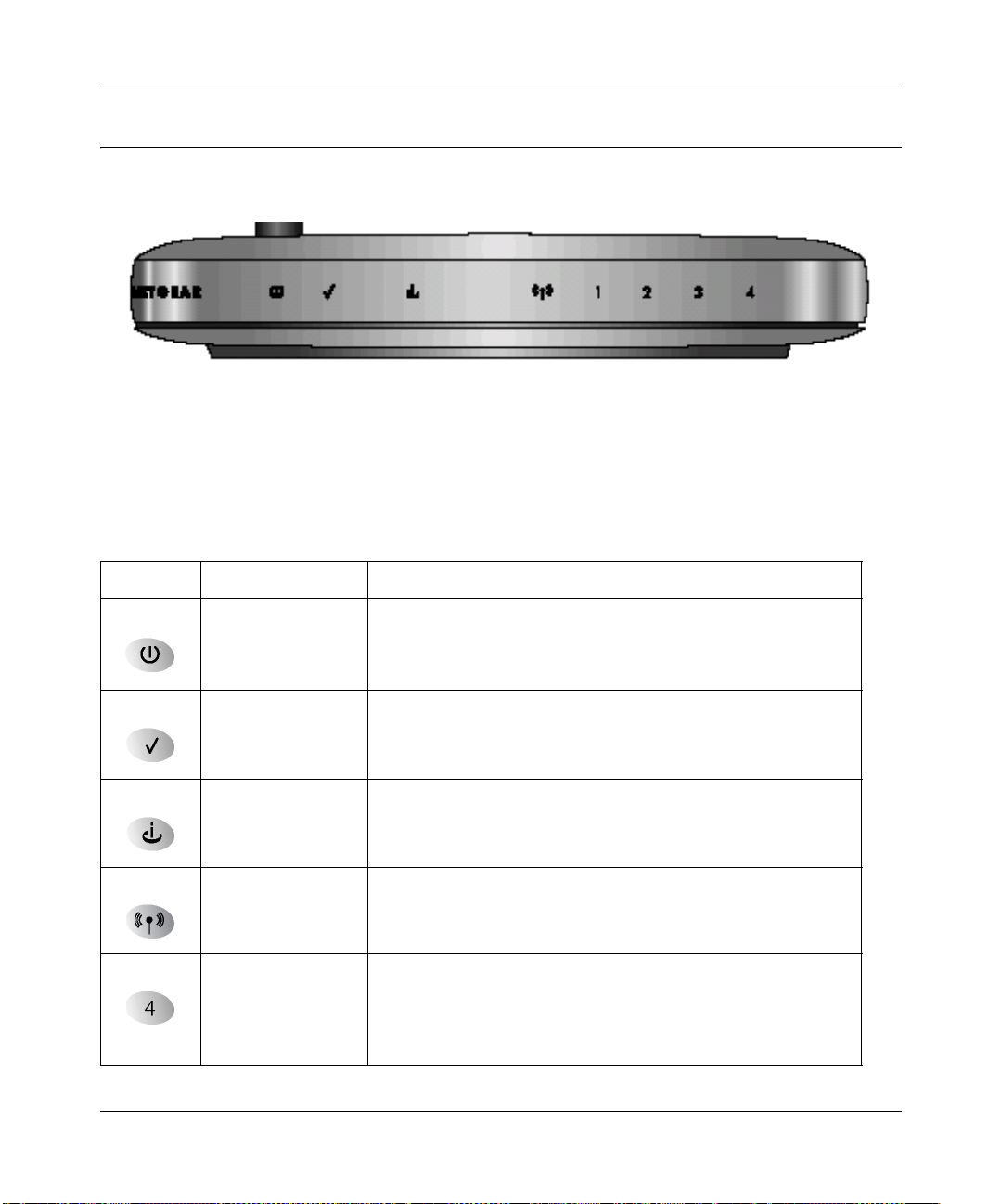
The front panel of the Model MR814 Wireless Router (Figure 2-1) contains status LEDs.
Figure 2-1. MR814 Front Panel
You can use some of the LEDs to verify connections. Table 2-1 lists and describes each LED on
the front panel of the router. These LEDs are green when lit.
Table 2-1. LED Descriptions
Label Activity Description
Power On
Off
Test On
Off
Internet On
Blink
Wireless On Indicates that the Wireless port is initialized.
LAN On (Green)
Blink (Green)
On (Amber)
Blink (Amber)
Off
Power is supplied to the router.
Power is not supplied to the router.
The system is initializing.
The system is ready and running.
The Internet port has detected a link with an attached device.
Data is being transmitted or received by the Internet port.
The Local port has detected link with a 100 Mbps device.
Data is being transmitted or received at 100 Mbps.
The Local port has detected link with a 10 Mbps device.
Data is being transmitted or received at 10 Mbps.
No link is detected on this port.
Setting Up the Hardware 2-3
Page 26

Reference Manual for the Model MR814 Wireless Router
The Router’s Rear Panel
The rear panel of the Model MR814 Wireless Router (Figure 2-2) contains port connections.
Figure 2-2. MR814 Rear Panel
Viewing right to left, the rear panel contains the following features:
• Wireless antenna
• Factory Default Reset push-button
• Internet Ethernet port for connecting the router to a cable or DSL modem
• Four Ethernet LAN ports for connecting the router to the local computers
• AC power adapter outlet
Connecting the Rout er
Before using your router, you need to do the following:
• Prepare your wireless devices as described below.
• Connect your local Ethernet network to the LAN port(s) of the router (see page 2-5).
• Connect your cable or DSL modem to the Internet port of the router (see page 2-5).
• Connect the pow er adapter (see page 2-6)
Note: The Resource CD included with your router contains an animated Installation Assistant to
help you through this procedure.
Preparing Wireless Connections
Rotate the antenna to a vertical position.
2-4 Setting Up the Hardware
Page 27

Reference Manual for the Model MR814 Wireless Router
Detailed instructions on configuring your wireless devices for TCP/IP networking are provided in
the next chapter. However, if you already ha ve a fu nction ing wir eless networ k and you wis h to us e
a wireless PC to initially configure the router, you will need to change the settings of that PC to
match the default settings of the router:
• The SSID should be Wireless (note t he capitalization).
• WEP encryption is disabled.
• Your IP address must be in the range of 192.168.0.2 to 192.168.0.254, with a netmask of
255.255.255.0
See Chapter 5 Wireless below for full details o n setting up wireless connections.
Connecting to Your Ethernet LAN
Your Ethernet network will attach to the four LAN ports on the router shown in Figure 2-2. The
LAN ports can operate at ei ther 10 Mbps (10 BASE-T) or 10 0 Mbps (100BASE-Tx), d epending on
the Ethernet adapters in th e attached compute rs, hub, or switch. You must use a Category 5 (CAT5)
rated Ethernet cable, such as the cable included with the router, for any connection which will
operate at 100 Mbps.
The Model MR814 router i ncorpo rates a fo ur -por t swit ch for c onnect ion to yo ur l ocal n etwork. To
connect the router to your LAN:
• Connect up to four computers directly to any of the four LAN ports of the router using
standard Ethernet cables.
• To connect more than 4 computers on the Ethernet LAN, you wil l need t o con nect your router
to another hub or switch.
– Connect any Local port of your router to the Uplink port of an Ethernet hub or switch
using a standard Ethernet cable.
OR
– Connect any Local port of your router to any normal port of an Ethernet hub or switch
using a crossover Ethernet cable.
Connecting to Your Internet Access Device
Using the Ethernet cable already attached to your cable modem or DSL modem, connect the
router’s Internet p ort to the Ethernet por t o n the modem. Turn the modem of f f or ten seconds, then
on again.
Setting Up the Hardware 2-5
Page 28

Reference Manual for the Model MR814 Wireless Router
Note: Your cable or DSL modem must provide a standard 10BASE-T Ethernet connection for
connection to your network. The router does not support USB modems.
Note: The Ethernet cable supplied by your ISP for connecting to your cable or DSL modem may
be an Ethernet crossover cable rather than a straight-through cable. It is important to use the
existing cable to connect the modem to your router, not to connect your PCs to your router.
Connecting the Power Adapter
To connect the router to the power adapter:
1. Plug the connector of the power adapter into the power adapter outlet on the rear panel of the
router.
2. Plug the other end of the adapter into a standard wall outlet.
3. Verify that the Power LED on the router is lit.
Verifying Power
After connecting the power adapter to the router and a power source, the router powers on
automatically. Complete the following steps to ver ify that power is correctly applied to the router:
1. When power is first applied, verify that the Power LED c omes on.
2. During the first 10 secon ds, all LEDs will be tested.
3. After approximately 10 seconds, verify that:
a. The Test LED is not lit.
b. The LAN port LEDs are lit for any local ports that are connected.
c. The Internet port LED is lit.
If a port’s LED is lit, a link has been established to the connected device. If a LAN port is
connected to a 100 Mbps de vice, veri fy that th e port’s LED is green. If the port is 10 Mbps, the
LED will be amber.
You are now ready to begin configuration of your network, as described in the following chapter.
2-6 Setting Up the Hardware
Page 29
Chapter 3
Preparing Your Network
This chapter describes how to prepare your PC network to connect to the Internet through the
Model MR814 Wireless Router and how to verify the readiness of a broadband DSL or cable
modem account from an Internet service provider (ISP).
Note: If an ISP technician configured your PC during the installation of a broadband
modem, or if you configur ed it us ing inst ructions provided by your IS P, you may need to
copy the current configuration information for use in the configuration of your router.
Write down this information before reconfiguring your PCs. Refer to “Obtaining ISP
Configuration Information for Windows Computers” on page 3-10 or “Obtaining ISP
Configuration Information for Macintosh Computers” on page 3-11 for further
information.
Preparing Your Computers for TCP/IP Networking
Computers access the Internet using a protocol called TCP/IP (Transmission Control Protocol/
Internet Protocol). Eac h comput er on your network must have TCP/IP installed and sel ect ed as its
networking protocol. I f a Net work I nterf ace Ca rd (NI C) is al ready inst alled in y our co mpute r, then
TCP/IP is probably already installed as well.
Most operating systems include the software components you need for networking with TCP/IP:
®
• Windows
• Windows 3.1 does not include a TCP/IP component. You need to purchase a third-party TCP/
IP application package such as NetManage Chameleon.
• Macintosh Operating System 7 or later includes the software components for establishing a
TCP/IP network.
Preparing Your Network 3-1
95 or later includes the software components for establishing a TCP/IP network.
Page 30

Reference Manual for the Model MR814 Wireless Router
• All versions of UNIX or Linux include TCP/IP components. Follow the instructi ons provided
with your operating system or networking software to install TCP/IP on your computer.
In your TCP/IP network, each computer and the router must be assigned a unique IP addresses.
Each computer must also have other TCP/IP configuration information such as a subnet mask, a
domain name server (DNS) address, and a default gateway address. In most cases, you should
install TCP/IP so that the computer obtains its network configuration information automatically
from a DHCP server during bootup. For a detailed explanation of the meaning and purpose of
these configuration items, refer to “Appendix B, “Networks, Routing, and Firewall Basics.”
The Model MR814 router is shipped preconfigured as a DHCP server. The router assigns the
following TCP/IP configuration information automatically when the computers are rebooted:
• PC, Macintosh, or workstation IP addresses—192.168.0.2 through 192.168.0.254
• Subnet mask—255.255.255.0
• Gateway (the router) address —192.168.0.1
Configuring Windows 95, 98, and ME for TCP/IP Networking
As part of the PC preparation process, you need to assure TCP/IP is installed and configured on
each networked PC. Before starting, locate your Windows CD which you may need to insert
during the TCP/IP installation process.
Installing or Verifying Windows Networking Components
To install or verify the necessa ry Windows components for TCP/IP net wor kin g foll ow the se st eps:
1. On the Wi ndows taskbar, cl ick the Start bu tt on, poi nt to Settings, and then click Control Panel.
2. Double-click the Network icon.
The Network window opens, which displays a list of installed components:
3-2 Preparing Your Network
Page 31

Reference Manual for the Model MR814 Wireless Router
You must have an Ethernet adapter, the TCP/IP protocol, and Client for Microsoft Networks.
Note: It is not necessary to remove any other network components shown in the
Network wi ndow in order to install the adapter, TCP/IP, or Client for Microsoft
Networks.
If you need to add the adapter:
a. Click the Add button.
b. Select Adapter, and then click Add.
c. Select the manufacturer and model of your Ethernet adapter, and then click OK.
If you need TCP/IP:
a. Click the Add button.
b. Select Protocol, and then click Add.
c. Select Microsoft.
Preparing Your Network 3-3
Page 32

Reference Manual for the Model MR814 Wireless Router
d.
Select TCP/IP, and then click OK.
If you need Client for Microsoft Networks:
a. Click the Add button.
b. Select Client, and then click Add.
c. Select Microsoft.
d. Select Client for Microsoft Networks, and then click OK.
3. Restart your PC for the changes to take effect.
Enabling DHCP to Automatically Configure TCP/IP Settings
After the TCP/IP protocol components are installed, each PC must be assigned specific
information about itself and resources that are available on its network. The simplest way to
configure this information is to allow the PC to obtain the information from the internal DHCP
server of the Model MR814 router. To use DHCP with the recommended default addresses, follo w
these steps:
1. Connect all PCs to the router, then restart the router and allow it to boot.
2. On each attached PC, open t he Net work con trol panel (ref er t o the pre vious secti on) an d sele ct
the Configuration tab.
3. From the components list, select TCP/IP->(your Ethernet adapter) and click Properties.
4. In the IP Address tab, select “Obtain an IP address automatically”.
5. Select the Gateway tab.
6. If any gateways are shown, remove them.
7. Click OK.
8. Restart the PC.
Repeat steps 2 through 8 for each PC on your network.
Selecting Windows’ Internet Access Method
To select Windows’ LAN Internet access method, follow these steps:
1. On the Wi ndows taskbar, cl ick the Start bu tt on, poi nt to Settings, and then click Control Panel.
2. Double-click the Internet Options ico n.
3-4 Preparing Your Network
Page 33

Reference Manual for the Model MR814 Wireless Router
3.
Select “I want to set up my Internet connection manually” or “I want to connect through a
Local Area Network” and click Next.
4. Select “I want to connect through a Local Area Network” and click Next.
5. Uncheck all boxes in the LAN Internet Configuration screen and click Next.
6. Proceed to the end of the Wizard.
Verifying TCP/IP Properties
After your PC is configured and has rebooted, you can check the TCP/IP configuration using the
utility winipcfg.exe:
1. On the Windows taskbar, click the Start button, and then click Run.
2. Type winipcfg, and then click OK.
The IP Configuratio n window opens, which list s (among ot her things ), your IP a ddress, su bnet
mask, and default gateway.
3. From the drop-down box, select your Ethernet adapter.
The window is updated to show your s etti ngs, which should mat ch the val ues bel ow if you ar e
using the default TCP/IP settings that NETGEAR recommends:
• The IP address is between 192.168.0.2 and 192.168.0.254
• The subnet mask is 255.255.255.0
• The default gateway is 192.168.0.1
Configuring Windows NT or 2000 for TCP/IP Networking
As part of the PC preparation process, you need to assure TCP/IP is installed and configured on
each networked PC. Before starting, locate your Windows CD which you may need to insert
during the TCP/IP installation process.
Install or Verify Windows Networking Components
To install or verify the necessary components for IP networking:
1. On the Wi ndows taskbar, cl ick the Start bu tt on, poi nt to Settings, and then click Control Panel.
2. Double-click the Network and Dialup Connections icon.
Preparing Your Network 3-5
Page 34

Reference Manual for the Model MR814 Wireless Router
3.
If an Ethernet adapter is present in your PC, you should see an entry for Local Area
Connection. Double-click that entry.
4. Select Properties.
5. Verify that ‘Client for Microsoft Networks’ and ‘Internet Protocol (TCP/IP)’ are present. If
not, select Install and add them.
6. Select ‘Internet Protocol (TCP/IP)’, click Properties, and verify that “Obtain an IP address
automatically is selected.
7. Click OK and close all Network and Dialup Connections windows.
8. Make sure your PC is connected to the router, then reboot your PC.
Verifying TCP/IP Properties
To check your PC’s TCP/IP configuration:
1. On the Windows taskbar, click the Start button, and then click Run.
The Run window opens.
2. Type cmd and then click OK.
A command window opens
3. Type ipconfig /all
Your IP Config uration i nformati on will be lis ted, and sh ould match t he values below if you ar e
using the default TCP/IP settings that NETGEAR recommends:
• The IP address is between 192.168.0.2 and 192.168.0.254
• The subnet mask is 255.255.255.0
• The default gateway is 192.168.0.1
4. Type exit
Configuring A Macintosh for TCP/IP Networking
Beginning with Macintosh Operating System 7, TCP/IP is already installed on the Macintosh. On
each networked Macintosh, you will need to configure TCP/IP to use DHCP.
3-6 Preparing Your Network
Page 35
Reference Manual for the Model MR814 Wireless Router
Configuring MacOS 8.6 or 9.x for TCP/IP Networking
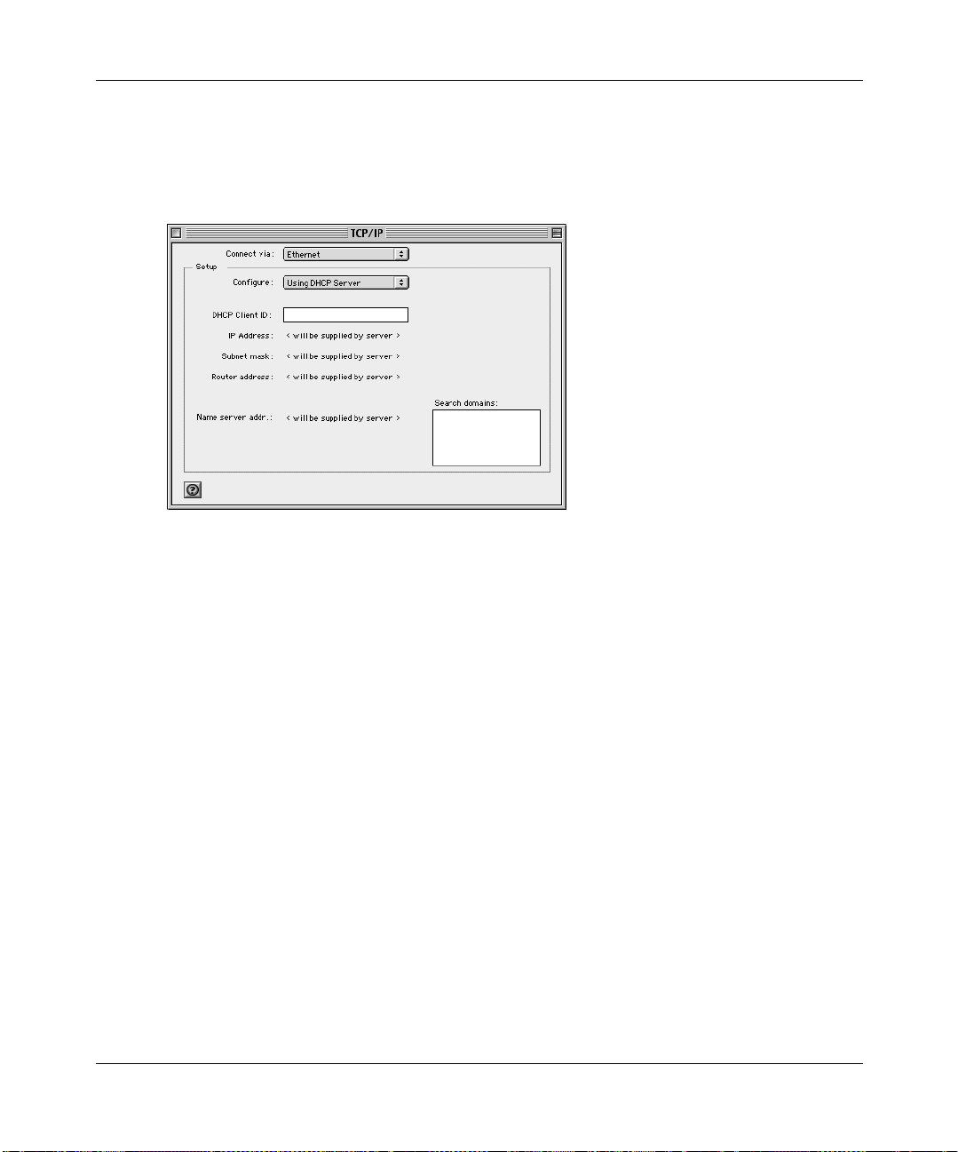
1. From the Apple menu, select Control Panels, then TCP/IP.
The TCP/IP Control Panel opens:
2. From the “Connect via” box, select your Macintosh’s Ethernet interface.
3. From the “Configure” box, select Using DHCP Server.
You can leave the DHCP Client ID box empty.
4. Close the TCP/IP Control Panel.
5. Repeat this for each Macintosh on your network.
Configuring MacOS X for TCP/IP Networking
1. From the Apple menu, choose System Preferences, then Network.
2. If not already selected, select Built-in Ethernet in the Configure list.
3. If not already selected, select Using DHCP in the TCP/IP tab.
4. Click Save.
Preparing Your Network 3-7
Page 36
Reference Manual for the Model MR814 Wireless Router
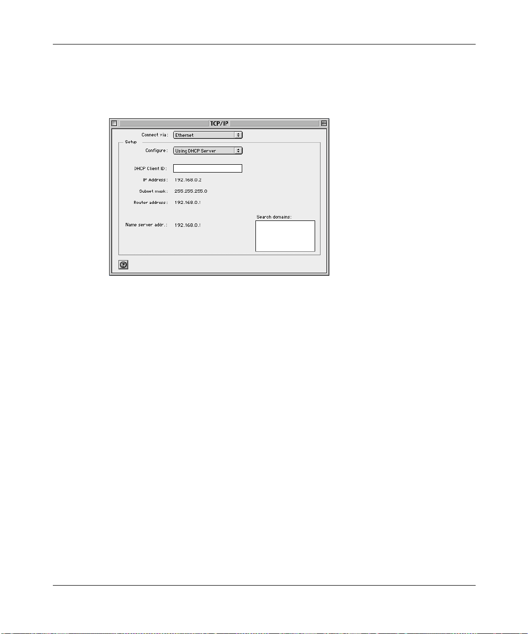
Verifying TCP/IP Properties for Macintosh Computers
After your Macintosh is configured and has rebooted, you can check the TCP/IP configuration by
returning to the TCP/IP Control Panel. From the A pple menu, select Control Panels, then TCP/IP.
The panel is updated to show your settings, which should match the values below if you are using
the default TCP/IP settings that NETGEAR recommends:
• The IP Address is between 192.168.0.2 and 192.168.0.254
• The Subnet mask is 255.255.255.0
• The Router address is 192.168.0.1
If you do not see these values, you may need to restart your Macintosh or you may need to switch
the “Configure” setting to a different option, then back again to “Using DHCP Server”.
3-8 Preparing Your Network
Page 37

Reference Manual for the Model MR814 Wireless Router
Verifying the Readiness of Your DSL or Cable Modem Internet Account
For access to the Internet, you need to c ontract with an Internet service provider (ISP) for a
single-user Internet access account using a cable modem or DSL modem. This modem must be a
separate physical box (not a card) and must provide an Ethernet port intended for connection to a
Network Interface Card (NIC) in a computer. Your router does not support a USB-connected
broadband modem.
For a single-user Internet account, your ISP supplies TCP/IP configuration information for one
PC. With a typical account, much of the configuration information is dynamically assigned when
your PC is first bo ote d up while connected to the ISP, and you will not ne ed t o kno w that dynamic
information.
In order to share the Internet connection among several computers, your router takes the place of
the single P C. You need to configure the router with the TCP/IP information that th e single PC
would normally use. When the router is connected to the broadband modem, the router appears to
be a single PC to the ISP. The router then allows multiple computers on the local network to
masquerade as the single PC to access the Internet through the broadband modem.
Are Login Protocols Used?
Some ISPs require a special l ogin pro tocol, in which you must enter a login name and password in
order to access the Internet. If you normally log in to your Internet account by running a program
such as WinPOET or EnterNet, then your account uses PPP over Ethernet (PPPoE).
When you configure your router, you will need to enter your login name and password in the
router’s configuration menus. After your network and router are configured, the router will
perform the login task when needed, and you will no longer need to run the login program from
your PC. It is not necessary to uninstall the login program.
What is Y our Configuration Information?
More and more, ISPs are dynamically assigning configuration information. However, if your ISP
does not dynamically ass ign conf ig urati on infor mation bu t in stead us ed fixe d configu rati ons, your
ISP should have given you the following basic information for your account:
Preparing Your Network 3-9
Page 38

Reference Manual for the Model MR814 Wireless Router
• An IP address and subnet mask
• A gateway IP address, which is the address of the ISP’s router
• One or more domain name server (DNS) IP addresses
• Host name and domain suffix
For example, your account’s full server names may look like this:
mail.xxx.yyy.com
In this example, the domain suffix is
xxx.yyy.com.
If any of these i tems ar e d ynami cally supplied by the I S P, your router automat ic al ly acquires them.
If an ISP technician configure d your PC during the instal lati on of the broadb and modem, or if you
configured it using instructions provided by your ISP, you need to copy the configuration
information from your PC’s Network TCP/IP Properties window or Macintosh TCP/IP Control
Panel before reconfiguring your PC for use with the router. These procedures are described next.
Obtaining ISP Configuration Information for Windows Computers
As mentioned above, yo u may nee d t o c ollect configuration information from your PC so t hat yo u
can use this information when you configure the Model MR814 rou ter. Following this procedure is
only necessary when your ISP does not dynamically supply the account information.
To get the in formation you need to configure the router for Internet access:
1. On the Wi ndows taskbar, cl ick the Start bu tt on, poi nt to Settings, and then click Control Panel.
2. Double-click the Network icon.
The Network window opens, which displays a list of installed components.
3. Select TCP/IP, and then click Properties.
The TCP/IP Properties dialog box opens.
4. Select the IP Address tab.
If an IP address and subnet mask are shown, write down the information. If an address is
present, your account uses a fixed (static) IP address. If no address is present, your account
uses a dynamically-assigned IP address. Click “Obtain an IP address automatically”.
5. Select the Gateway tab.
If an IP address appears under Installed Gateways, write down the address. This is the ISP’s
gateway address. Select the address and then click Remove to remove the gateway address.
3-10 Preparing Your Network
Page 39

Reference Manual for the Model MR814 Wireless Router
6.
Select the DNS Configuration tab.
If any DNS server addresses are shown, write down the addresses. If any information appears
in the Host or Domain information box, write it down. Click Disable DNS.
7. Click OK to save your changes and close the TCP/IP Properties dialog box.
You are returned to the Network window.
8. Click OK.
9. Reboot your PC at the prompt. You may also be prompted to insert your Windows CD.
Obtaining ISP Configuration Information for Macintosh Computers
As mentioned above, you may need to collect configuration information from your Macintosh so
that you can use this information when you configure the Model MR814 router. Following this
procedure is only necessary when your ISP does not dynamically supply the account information.
To get the in formation you need to configure the router for Internet access:
1. From the Apple menu, select Control Panels, then TCP/IP.
The TCP/IP Control Panel opens, which displays a list of configuration settings. If the
“Configure” setting is “Using DHCP Server”, your account uses a dynamically-assigned IP
address. In this case, close the Control Panel and skip the rest of this section.
2. If an IP address and subnet mask are shown, write down the information.
3. If an IP address appears under Router address, write down the address. This is the ISP’s
gateway address.
4. If any Name Server addresse s are shown , write down the addresses . These are you r ISP’s DNS
addresses.
5. If any information appears in the Search domains information box, write it down.
6. Change the “Configure” setting to “Using DHCP Server”.
7. Close the TCP/IP Control Panel.
Preparing Your Network 3-11
Page 40

Reference Manual for the Model MR814 Wireless Router
Restarting the Network
Once you’ve set up your computers to work with the router, you must reset the network for the
devices to be able to communicate correctly.
1. Turn off the DSL or cable modem, wait 15 seconds, and then turn it on again
2. Turn off the router, and then turn it on again and wait about 10 seconds until the Test light
turns off.
3. Restart any computer that is connected to the router.
Note: If the modem doesn’t have an on/off switch pull the modem’s power adapter out of the wall
socket or power strip.
Ready for Configuration
After configuring all of your computers for TCP/IP networking and connecting them to the local
network of your Model MR814 router, y ou are re ady to acc ess and c onfigure the route r. Procee d to
the next chapter.
3-12 Preparing Your Network
Page 41

Chapter 4
Basic Configuration of the Route r
This chapter describes how to perform the basic configuration of your Model MR814 Wireless
Router using the Setup Wizard, which walks you through the configuration process for your
Internet connectio n.
Accessing the Web Configuration Manager
In order to use the browser-based Web Configuration Manager , y our PC must have a web browser
program installed such as Microsoft Internet Explorer or Netscape Navigator. Because the
Configuration Manager uses Java, your Web browser must be Java-enabled and support HTTP
uploads. NETGEAR recommends using Microsoft Internet Explorer 5.0 or Netscape Navigator
4.7 or above. Free browser programs are readily available for Windows, Macintosh, or UNIX/
Linux.
To configure for Internet access using your browser:
1. Turn on the router and wait for initialization to complete.
Allow at least ten seconds and verify that the Test LED is off.
2. Reboot your computer to obtain DHCP configuration from the router.
3. Launch your web browser.
Note: If you normally use a login program such as Enternet or WinPOET to access the
Internet, do not launch that program.
4. Click your browser’s Stop button.
5. In the Address or Location box of your browser, type http://192.168.0.1 and press ENTER.
Basic Configuration of the Router 4-1
Page 42

Reference Manual for the Model MR814 Wireless Router
A login window opens as shown in Figure 4-1 below:.
Figure 4-1. Login window
This screen may have a different appearance in other browsers.
6. Type admin in the User Name box, password in the Password box, and then click OK. The
User Name and Password are case sensitive.
If your router password was previously changed, enter the current password.
If your router has not yet been configured, the Setup Wizard should launch automatically.
Otherwise, the main menu of the Web Configuration Manager will appear as shown in Figure 4-2
below:
4-2 Basic Configuration of the Router
Page 43

Reference Manual for the Model MR814 Wireless Router
Figure 4-2. Browser-based configuration main menu
You can manually configure your router using this menu as described in “Configuring Manually“
on page 4-8, or y ou can al low the Setup Wizard to d etermine your conf iguration a s descri bed in the
following ch apter.
Basic Configuration of the Router 4-3
Page 44

Reference Manual for the Model MR814 Wireless Router
Using the Setup Wizard
The Web Configuration Manager contains a Setup Wizard that can automatically determine your
network connection type. If the Setup Wizard does not launch automatically, click on the Setup
Wizard heading in the upper left of the opening screen, shown in Figure 4-2.
When the Wizard launches, allow the router to automatically determine your connection type by
selecting Yes in the menu below and clicking Next:
The Setup Wizard will now check for a connection on the Internet port. If the Setup Wizard
determines that there is no connection to the Internet port, you will be prompted to check the
physical connection between your router and cable or DSL modem. When the connection is
properly made, the router’s Internet LED should be on.
Next, the Setup Wizard will attempt to determine which of the following connection types
your Internet service account uses:
• Dynamic IP assignment
• Fixed IP address assignment
• A login protocol such as PPPoE
The Setup Wiz ar d will report which connection typ e it has di scovered, and it will then use the
appropriate configuration menu for that connection type.
4-4 Basic Configuration of the Router
Page 45

Reference Manual for the Model MR814 Wireless Router
Configuring Dynamic IP Accounts
If the Setup W iza rd dete rmin es that your Int ernet servic e accoun t uses Dyna mic IP assign ment via
DHCP, you will be directed to the menu shown in Figure 4-3 below:
Figure 4-3. Setup Wizard menu for Dynamic IP address
1.
Enter your Account Name (may also be called Host Name) and Domain Name. These
parameters may be ne cessary to acc ess your ISP’s services such as mai l or news servers . If yo u
leave the Domain Name field blank, the router will attempt to learn the domain automatically
from the ISP. If this is not successful, you may need to enter it manually.
2. Domain Name Server (DNS) Address: If you know that your ISP does not automatically
transmit DNS addresses to the router during login, select “Use these DNS servers” and enter
the IP address of your ISP’s Primary DNS Server. If a Secondary DNS Server address is
available, enter it also.
A DNS server is a host on the Internet that translates Internet names (such as www
addresses) to numeri c IP address es. Typically your ISP transfers the IP addresses of one or
two DNS servers to your router during login. If the ISP does not transfer an address, you
must obtain it from the ISP and enter it manually here. If you enter an address here, you
should reboot the computers on your network after configuring the router.
Basic Configuration of the Router 4-5
Page 46

Reference Manual for the Model MR814 Wireless Router
3.
Router’s MAC Address: This section determines the Ethernet MAC address that will be used
by the router on the In terne t port. If your I SP allows access by only one specif ic PC’s Ethernet
MAC address, select "Use this MAC address." The router will then capture and use the MAC
address of the PC that you are now using. You must be using the on e PC that is allowed b y t he
ISP.
Some ISPs will register the Ethernet MAC address of the network interface card in your
PC when your account is first opened. They will then only accept traffic from the MAC
address of that PC. This feature allows your router to masquerade as that PC by using its
MAC address.
4. Click on Apply, then proceed to “Completing the Configuration“ on page 4-9.
Configuring Fixed IP Accounts
If the Setup Wizard determines that your Internet service account uses Fixed IP assignment, you
will be directed to the menu shown in Figure 4-4 below:
Figure 4-4. Setup Wizard menu for Fixed IP address
1.
Enter your assigned IP Address, Subnet Mask, and the IP Address of your ISP’s gateway
router. This information should have been provided to you by your ISP.
2. Domain Name Server (DNS) Address: If you know that your ISP does not automatically
transmit DNS addresses to the router during login, select “Use these DNS servers” and enter
the IP address of your ISP’s Primary DNS Server. If a Secondary DNS Server address is
available, enter it also.
4-6 Basic Configuration of the Router
Page 47

Reference Manual for the Model MR814 Wireless Router
A DNS server is a host on the Internet that translates Internet names (such as www
addresses) to numeri c IP address es. Typically your ISP transfers the IP addresses of one or
two DNS servers to your router during login. If the ISP does not transfer an address, you
must obtain it from the ISP and enter it manually here. If you enter an address here, you
should reboot your PCs after configuring the router.
3. Click on Apply, then proceed to “Completing the Configuration“ on page 4-9.
Configuring Login Accounts
If the Setup Wizard determines that your Internet service account uses a login protocol such as
PPP over Ethernet (PPPoE), you will be directed to a menu like the PPPoE menu shown in
Figure 4-5 below:
Figure 4-5. Setup Wizard menu for PPPoE login accounts
Enter your Account Name (may also be called Host Name) and Domain Name. These
1.
parameters may be ne cessary to acc ess your ISP’s services such as mai l or news servers . If yo u
leave the Domain Name field blank, the router will attempt to learn the domain automatically
from the ISP. If this is not successful, you will need to enter it manually.
2. Enter the PPPoE login user name and password provided by your ISP. These fields are case
sensitive. If you wish to change the login time-out, enter a new value in minutes.
Basic Configuration of the Router 4-7
Page 48

Reference Manual for the Model MR814 Wireless Router
Note: You will no longer need to launch the ISP’s login prog ram on yo ur PC in ord er to acc ess
the Internet. When you start an Internet application, your router will automatically lo g you in.
3. Domain Name Server (DNS) Address: If you know that your ISP does not automatically
transmit DNS addresses to the router during login, select “Use these DNS servers” and enter
the IP address of your ISP’s Primary DNS Server. If a Secondary DNS Server address is
available, enter it also.
A DNS server is a host on the Internet that translates Internet names (such as www
addresses) to numeri c IP address es. Typically your ISP transfers the IP addresses of one or
two DNS servers to your router during login. If the ISP does not transfer an address, you
must obtain it from the ISP and enter it manually here. If you enter an address here, you
should reboot your PCs after configuring the router.
4. Click on Apply, then proceed to “Completing the Configuration“ on page 4-9.
Configuring Manually
You can manual ly con figur e the ro uter i n the Bas ic Set tings menu sh own in Figure 4-2 using these
steps:
1. Select whether your Internet connection requires a login.
Select ‘Yes’ if you normally must launch a login program such as Enternet or WinPOET in
order to access the Internet.
2. Enter your Account Name (may also be called Host Name) and Domain Name. These
parameters may be necessary to access your ISP’s services such as mail or news servers.
3. (If displayed) Enter the PPPoE login user name and password provided by your ISP. These
fields are case sensitive. If you wish to change the login time-out, enter a new value in
minutes.
Note: You will no longer need to launch the ISP’s login prog ram on yo ur PC in ord er to acc ess
the Internet. When you start an Internet application, your router will automatically lo g you in.
4. Internet IP Address: If your ISP has assigned you a permanent, fixed (static) IP address for
your PC our router, select “Use static IP address”. Enter the IP address that your router has
been assig ned. Also enter the netmask and the Gateway IP addr ess. The Gateway is the ISP’s
router to which your router will connect.
4-8 Basic Configuration of the Router
Page 49

Reference Manual for the Model MR814 Wireless Router
5.
Domain Name Server (DNS) Address: If you know that your ISP does not automatically
transmit DNS addresses to the router during login, select “Use these DNS servers” and enter
the IP address of your ISP’s Primary DNS Server. If a Secondary DNS Server address is
available, enter it also.
A DNS server is a host on the Internet that translates Internet names (such as www
addresses) to numeri c IP address es. Typically your ISP transfers the IP addresses of one or
two DNS servers to your router during login. If the ISP does not transfer an address, you
must obtain it from the ISP and enter it manually here. If you enter an address here, you
should reboot your PCs after configuring the router.
6. Router’s MAC Address: This section determines the Ethernet MAC address that will be used
by the router on the Internet port. Some ISPs will register the Ethernet MAC address of the
network interface card in your PC when your account is first opened. They will then only
accept traffi c from the MAC addr ess of that PC. This feature allows your router to masquerade
as that PC by “cloning” its MAC address. You can specify the MAC address in one of two
ways:
a. Select "Use this Computer’s MAC address." The router will then capture and use the
MAC address of the PC that you are now using. You must be using the one PC that is
allowed by the ISP.
b. Select "Use this MAC address" and manually enter the MAC address you wish to use.
7. Click on Apply, then proceed to “Completing the Configuration“ on page 4-9.
Completing the Configuration
Click on the Test button to test your Internet connection. If the NETGEAR website does not
appear within one minute, refer to Chapter 9, “Troubleshooting”.
Your router is now configured to provide Internet access for your network. When your router and
PCs are configured correctly, your router automatically accesses the Internet when one of your
LAN devices requires access. It is not necessary to run a dialer or login application such as
Dial-Up Networking or Enternet to connect, log in, or disconnect. These functions are performed
by the router as needed.
To access the Internet from any PC connected to your router, launch a browser such as Microsoft
Internet Explorer or Netscape Navigator. You should see the router’s Internet LED blink,
indicating communication to the ISP. The browser should begin to display a Web page.
The following chapters describe how to configure the Advanced features of your router, and how
to troubleshoot problems that may occur.
Basic Configuration of the Router 4-9
Page 50

Reference Manual for the Model MR814 Wireless Router
4-10 Basic Configuration of the Router
Page 51
Chapter 5
Wireless Configuration
This chapter describes how to configure the wireless features of your Model MR814 Wireless
Router.
Note: If you are configuring the router from a wireless PC and you change the router’s
SSID, channel, or WEP settings, you will lose your wireless connection when you click
on Apply. You must then change the wireless settings of your PC to match the router’s
new settings.
Considerations For A Wireless Network
In planning your wireless network, you should consider the level of security required. You should
also select the physical placement of your router in order to maximize the network speed. For
further information on wireless networking, refer to “Wireless Networking” in Appendix B,
“Network and Routing Basics.”
Security
Unlike wired network data, your wireless data transmissions can extend beyond your walls and
can be received by anyone with a compatible adapter. For this reason, NETGEAR strongly
recommends that you mak e use of t he securi ty featu res of you r wireles s equipment . As a minimum
security precaution, you should change the SSID setting of all devices on your network from the
factory setting to a unique password. Restricting access by MAC address filtering adds another
obstacle against unwanted hosts joining your network. To hinder a determined eavesdropper, you
should enable Wired Equivalent Privacy (WEP) data encryption. However, there may be a
significant degradation of the data throughput on the wireless link when WEP is enabled.
Wireless Configuration 5-1
Page 52
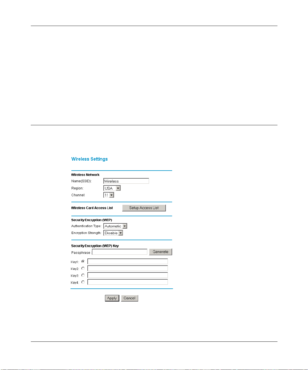
Reference Manual for the Model MR814 Wireless Router
Placement and Range
The operating distance or range of your wireless connection can vary significantly based on the
physical placement of the wireless router. For best results, place your router:
• near the center of the area in which your PCs will operate,
• in an elevated location such as a high shelf,
• away from potential sources of interference, such as PCs, microwaves, and cordless phones,
• away from large metal surfaces.
Wireless Settings
T o con figure th e W ire less inte rface of your router , click on t he W ire less head ing in t he Main Me nu
of the browser interface. The Wireless Settings menu will appear, as shown in Figure 5-1:
Figure 5-1. Wireless Settings menu
5-2 Wireless Configuration
Page 53
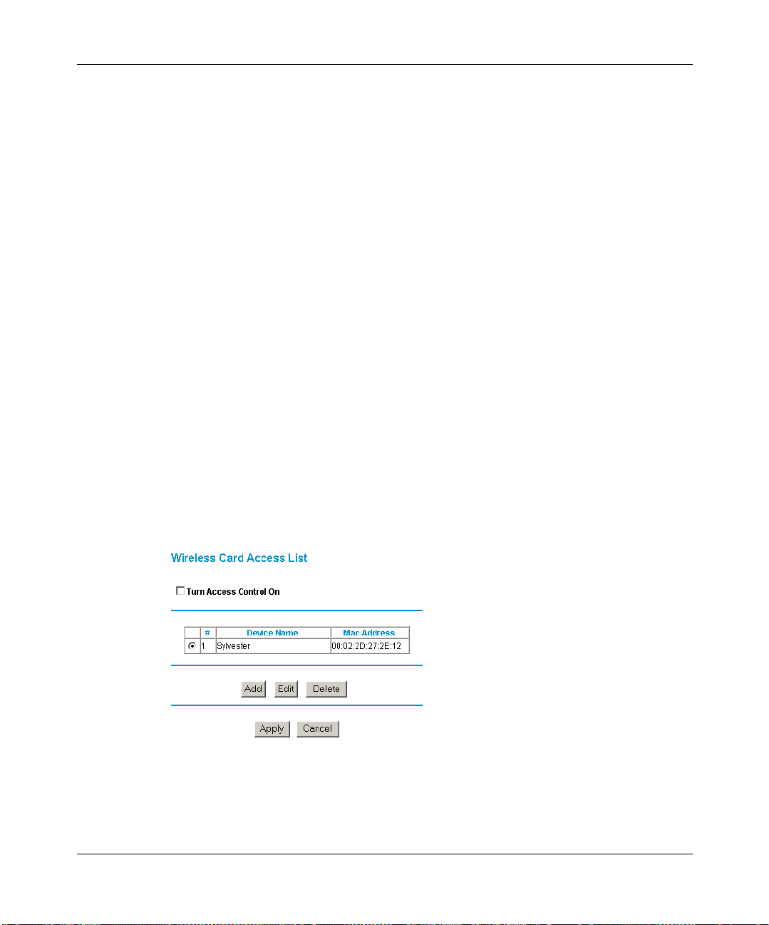
Reference Manual for the Model MR814 Wireless Router
Wireless Ne t work Setting s
In the Wireless Network section are the following paramete rs:
• SSID (Service Set ID)
Enter a value of up to 32 alphanumeric characters. The same SSID must be assigned to all
wireless devices in your network. The default SSID is Wireless, but NETGEAR strongly
recommends that you change your network’s SSID to a different value.
•Region
This field displays the region of operation for which the wireless interface is intended. It may
not be legal to operate the router in a region other than the region shown here.
• Channel
This field determines which operating frequency will be used. It should not be necessary to
change the wireless channel unless you notice interference problems with another nearby
access point.
Be sure to click Apply to save any settings from this menu.
Restricting Wireless Access by MAC Address
By default, any wirele ss PC tha t is conf igured wit h the cor rect SSID wi ll be allowed access to your
wireless network. For increased security, you can restrict access to the wireless network to only
allow specific PCs based on their MAC addresses. From the Wireless Settings menu, click the
Setup Access List button to display the Wireless Access List menu, shown in Figure 5-2:
Figure 5-2. Wireless Access List menu
Wireless Configuration 5-3
Page 54
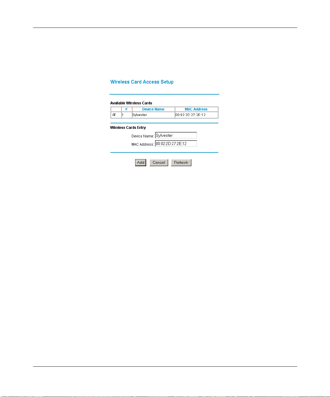
Reference Manual for the Model MR814 Wireless Router
The Wireless Access window displays a list of MAC addresses that will be allowed to connect to
the router. These PCs must also have the correct SSID and WEP settings. To restrict access based
on MAC addresses:
1. Click the Add button to go to the Add/Edit menu shown in Figure 5-3:
Figure 5-3. Wireless Access Setup menu
For your convenience, this menu displays a list of currently active wireless cards and their
Ethernet MAC addresses.
2. If the desired PC appears in the list, you can click on it to capture its MAC address; otherwise,
you can manually enter the MAC address of the authorized PC.
The MAC address is usually printed on the wireless card.
3. If no Device Name appears, you can type a descriptive name for the PC that you are adding.
4. Click Add.
5. When you have finished entering MAC addresses, return to the Wireless Access List menu
and check the Turn Access Control On box, then click Apply.
To edit a MAC address from the table, click on it to select it, then click the Edit or Delete button.
Configuring Wired Equivalent Privacy (WEP)
In the Wireless Settings menu you can configure WEP data encryption using the following
parameters:
5-4 Wireless Configuration
Page 55

Reference Manual for the Model MR814 Wireless Router
• Authentication Type
Normally this can be left at the default value of "Automatic." If that fails, select the
appropriate value - "Open System" or "Shared Key." Check your wireless card's
documentation to see what method to use.
• Encryption Strength
Select the WEP Encryption level:
• Off - no data encryption (Open System)
• 64-bit (sometimes called 40-bit) encryption
• 128-bit encryption
•Keys
If WEP is enabled, you can manually or automatically program the four data encr ypt io n keys .
These values must be identical on all PCs and Access Points in your network.
• Automatic - Enter a word or group of printable characters in the Passphrase box and click
the Generate button. The four key boxes will be automatically populated with key values.
• Manual - Enter ten hexadecimal digits (any combination of 0-9, a-f, or A-F)
Select which of the four keys will be active.
Be sure to click Apply to save your settings in this menu.
Wireless Configuration 5-5
Page 56

Reference Manual for the Model MR814 Wireless Router
5-6 Wireless Configuration
Page 57

Chapter 6
Content Filtering
This chapter describes how to use the Content Filtering features of your Model MR814 Wireless
Router. These features can be found by clicking on the Content Filtering heading in the Main
Menu of the browser interface.
Configuring for Content Filtering
The Model MR814 Wireless Router provides you with Web content filtering options, plus
browsing activity reporting and instant alerts via e-mail. Parents and network administrators can
establish restricted access policies based on time-of-day, web addresses and web address
keywords. You can also block Internet access by applications and services, such as chat or games.
To configure these features of your router, click on the subheadings under the Content Filtering
heading in the Main Menu of the browser interface. The subheadings are described below:
Content Filtering 6-1
Page 58

Reference Manual for the Model MR814 Wireless Router
Logs
The log is a detailed record of what websites you have accessed or attempted to access. Up to 128
entries are stored in the log. Log entries will only appear when keyword blocking is enabled, and
no log entries will be made for the Trusted User. An example is shown in Figure 6-1 below:
Figure 6-1. Logs menu
Log entries are described in Table 6-1
Table 6-1. Log entry descriptions
Field Description
Number The index number of the content filter log entries. 128 entries
are available numbered from 0 to 127. The log will keep the
record of the latest 128 entries.
Date and Time The date and time the log entry was recorded.
Source IP The IP address of the initiating device for this log entry.
Action This field displays whether the access was blocked or allowed.
The name or IP address of the website or newsgroup visited or
attempted to access.
6-2 Content Filtering
Page 59

Reference Manual for the Model MR814 Wireless Router
Log action buttons are described in Table 6-2
Table 6-2. Log action buttons
Field Description
Refresh Click this button to refresh the log screen.
Clear Log Click this button to clear the log entries.
Send Log
Click this button to email the log immediately.
Block Sites
The Model MR814 router allows you to restrict access based on web addresses and web address
keywords. Up to 255 entries are supported in the Keyword list. The Block Sites menu is shown in
Figure 6-2 below:
Figure 6-2. Block Sites menu
Content Filtering 6-3
Page 60

Reference Manual for the Model MR814 Wireless Router
To enable keyword blocking, select either “Per Schedule” or “Always”, then click Apply. If you
want to block by schedule, be sure that a time period is specified in the Schedule menu.
To add a keyword or domain, type it in the Keyword box, click Add Keyword, then click Apply.
To delete a keyword or domain, select it from the list, click Delete Keyword, then click Apply.
Keyword application examples:
• If the keyword "XXX" is specified, the URL <http://www.badstuff.com/xxx.html> is blocked.
• If the keyword “.com” is specified, only websites with other domain suffixes (such as .edu or
.gov) can be viewed.
• If you wish to block all Interne t brows ing acc ess dur ing a sc hedule d pe riod, e nter t he keywor d
“.” and set the schedule in the Schedule menu.
To specify a Trusted User, enter that PC’s IP address in the Trusted User box and click Apply.
You may specify one Trusted User, which is a PC that will be exempt from blocking and
logging. Since the Trusted User will be identified by an IP address, you should configure that
PC with a fixed IP address.
Block Services
The Model MR814 router allows you to block the use of certain Internet services by PCs on your
network. This is called services blocking or port filtering. The Block Services menu is shown in
Figure 6-3 below:
Figure 6-3. Block Services menu
6-4 Content Filtering
Page 61

Reference Manual for the Model MR814 Wireless Router
Services are functions performed by server computers at the request of client computers. For
example, Web servers serve web pages, time servers serve time and date information, and game
hosts serve data about othe r players ’ moves. When a computer on your net work sends a request for
service to a server computer on the Internet, the requested service is identified by a service or por t
number. This number appears as the destination port number in the transmitted IP packets. For
example, a packet that is sent with destination port number 80 is an HTTP (Web server) request.
To enable service blocking, select either “Per Schedule” or “Always”, then click Apply. If you
want to block by schedule, be sure that a time period is specified in the Schedule menu.
To specify a service for blocking, click Add. The Add Services menu will appear, as shown in
Figure 6-4 below:
Figure 6-4. Add Services menu
From the Service Type list, select the application or service to be allowed or blocked. The list
already displays several common services, but you are not limited to these choices. To add any
additional services or applications that do not already appear, select User Defined.
Content Filtering 6-5
Page 62

Reference Manual for the Model MR814 Wireless Router
User Defined Service
To define a service, first you must determine which port number or range of numbers is used by
the application. The service numbers for many common protocols are defined by the Internet
Engineering Task Force (IETF) and published in RFC1700, “Assigned Numbers.” Service
numbers for other applicat ions are typical ly ch osen from t he range 1024 to 6553 5 by th e authors of
the application. This information can usually be determined by contacting the publisher of the
application or from user groups of newsgroups.
Enter the St arting Port and En ding Port numbers. If the appl ication uses a single port number, enter
that number in both boxes.
If you know that the appli cation us es either TCP or UDP, select the appropriate p rotocol. I f you are
not sure, select Both.
IP Address Range
Under “Filter IP”, you can block the specified service for a single PC, a range of PCs (having
consecutive IP addresses), or all PCs on your network.
6-6 Content Filtering
Page 63

Reference Manual for the Model MR814 Wireless Router
Schedule
The Model MR814 router allows you to specify when blocking will be enforced. The Schedule
menu is shown in Figure 6-5 below:
Figure 6-5. Schedule menu
• Use this schedule for blocking content
Check this box if you wish to enable a schedule for Cont ent Filtering. Click Apply.
•Days to Block
Select days to block by checking the appropriate boxes. Select Everyday to check the boxes
for all days. Click Apply.
• Time of Day to Block
Select a start and end time in 23:59 format. Select All day for 24 hour blocking. Click Apply.
Be sure to select your Time Zone in the E-Mail menu.
Content Filtering 6-7
Page 64
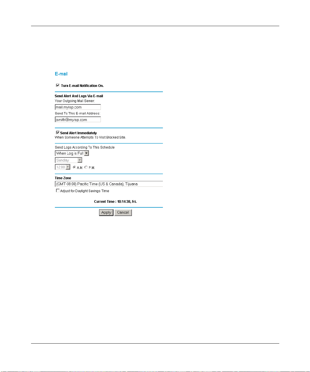
Reference Manual for the Model MR814 Wireless Router
In order to receive logs and aler ts by email, you must provide your email information in the E-Mail
menu, shown in Figure 6-6 below:
Figure 6-6. Email menu
• Turn e-mail notification on
Check this box if you wish to receive e-mail logs and alerts from the router.
• Your outgoing mail server
Enter the name of your ISP’s outgoing (SMTP) mail server (such as mail.myISP.com). You
may be able to find this information in the configuration menu of your e- mai l program. If you
leave this box blank, log and alert messages will not be sent via e-mail.
• Send to this e-mail address
Enter the e-mail add ress to which l ogs and al erts are sent. Thi s e-mail address will also be used
as the From address. If you leave this box blank, log and alert messages will not be sent via
e-mail.
6-8 Content Filtering
Page 65

Reference Manual for the Model MR814 Wireless Router
You can specify that logs are automatically sent to the specified e-mail address with these options:
• Send alert immediately
Check this box if you would like immediate notification of attempted access to a blocked site.
• Send logs according to this schedule
Specifies how often to send the logs: Hourly, Daily, Weekly, or When Full.
– Day for sending log
Specifies which day of the week to send the log. Relevant when the log is sent weekly or
daily.
– Time for sending log
Specifies the time of day to send the log. Relevant when the log is sent daily or weekly.
If the Weekly, Daily or Hourly option is selected and the log fills up before the specified
period, the log is automatically e-mail ed to the specified e-mail address. Afte r the log is sent,
the log is cleared from the router’s memory. If the router cannot e-mail the log file, the log
buffer may fill up. In this case, the router overwrites the log and discards its contents.
The Model MR814 router uses the Network Time Protocol (NTP) to obtain the current time and
date from one of several Network Time Servers on the Internet. In order to localize the time for
your log entries, you must specify your Time Zone:
•Time Zone
Select your local time zone. This setting will be used for the blocking schedule and for
time-stamp ing log entries.
• Daylight Savings Time
Check this box if your time zone is currently under daylight savings time.
Content Filtering 6-9
Page 66

Reference Manual for the Model MR814 Wireless Router
6-10 Content Filtering
Page 67
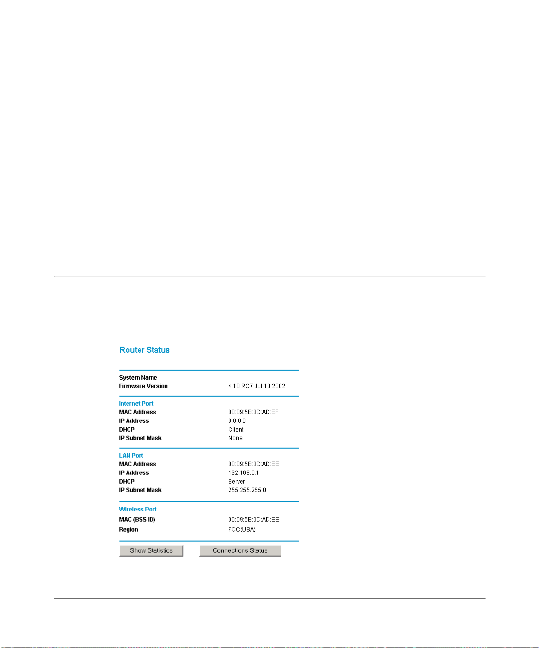
Chapter 7
Maintenance
This chapter describes how to use the maintenance features of your Model MR814 Wireless
Router. These features can be f ound by clicking on the Mainte nance heading in the Main Menu of
the browser interface.
System Status
The System Status menu provides a limited amount of status and usage information. From the
Main Menu of the browser interface, click on Maintenance, then select System Status to view the
System Status screen, shown in Figure 7-1.
Figure 7-1. System Status screen
Maintenance 7-1
Page 68

Reference Manual for the Model MR814 Wireless Router
This scree n shows the following par ameters:
Table 7-1. Menu 3.2 - System Status Fields
Field Description
System Name This field displays the Host Name assigned to the router.
Firmware Version This field displays the router firmware version.
Internet Port These parameters apply to the Internet (WAN) port of the router.
MAC Address T his fiel d displ ays the Etherne t MAC add ress being us ed by the In ternet
(WAN) port of the router.
IP Address This field displays the IP add res s be ing us ed b y the Inte rnet (WAN) port
of the router. If no address is shown, the router cannot connect to the
Internet.
IP Subnet Mask This field displ ays the IP Subnet Ma sk being used by the Internet (W AN)
port of the router.
DHCP If set to None, the router is configured to use a fixed IP address on the
WAN.
If set to Client, the router is configured to obtain an IP address
dynamically from the ISP.
LAN Port These parameters apply to the Local (WAN) port of the router.
MAC Address This field displays the Ethernet MAC address being used by the Local
(LAN) port of the router.
IP Address This field displays the IP address being used by the Local (LAN) port of
the router. The default is 192.168.0.1
IP Subnet Mask This field displays the IP Subnet Mask being used by the Local (LAN)
port of the router. The default is 255.255.255.0
DHCP If set to None, the router will not assign IP addresses to local PCs on the
LAN.
If set to Server, the router is configured to assign IP addresses to local
PCs on the LAN.
Wireless Port These parameters apply to the Wireless port of the router.
MAC (BSS ID) This field displays the Ethernet MAC address being used by the
Wireless Port. This will be the same MAC address as the Local (LAN)
port of the router.
Region This field displays the region of legal operatio n for the wireless interface.
7-2 Maintenance
Page 69
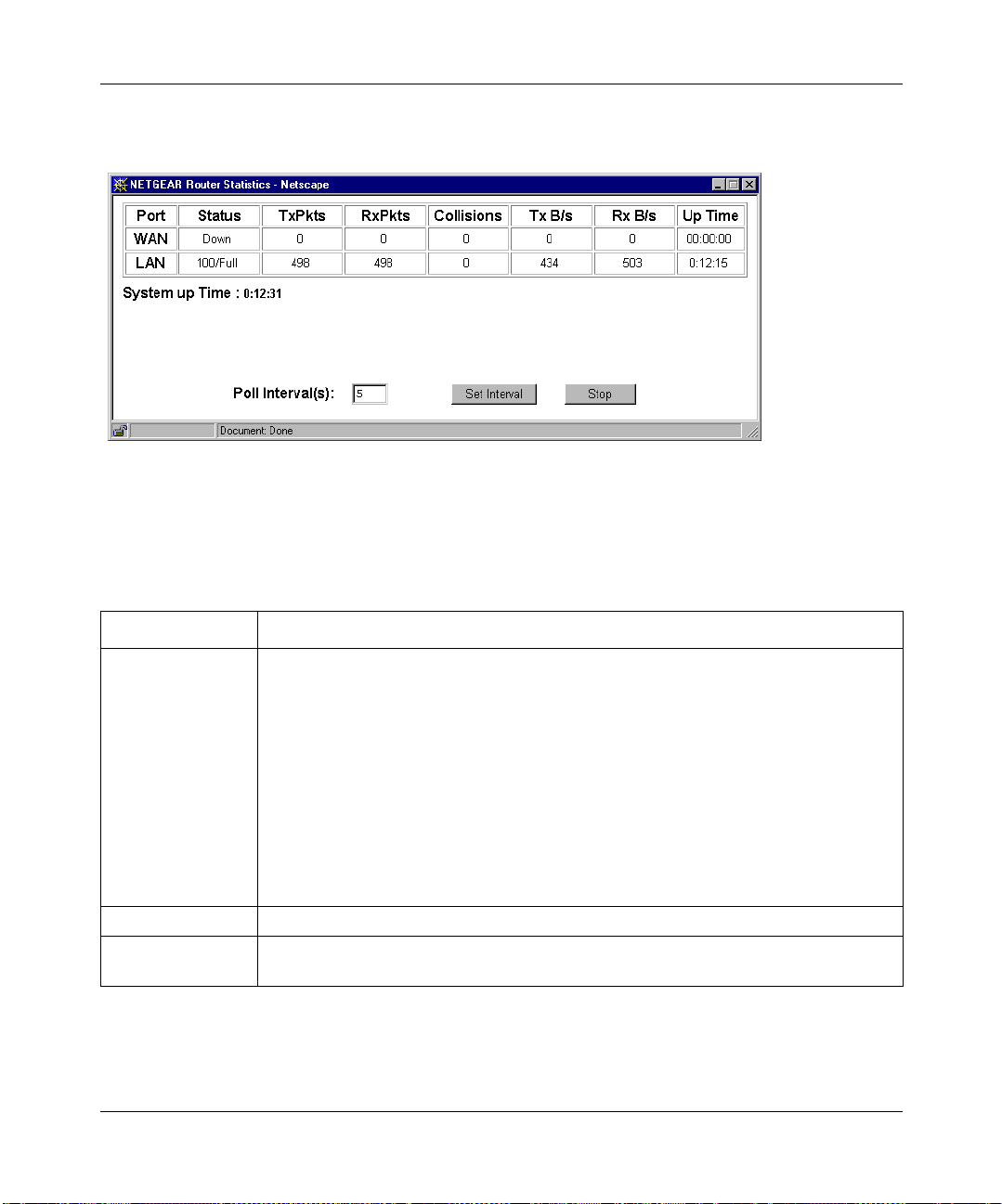
Reference Manual for the Model MR814 Wireless Router
Click on the “Show Statistics” button to display router usage statistics, as shown in Figure 7-2
below:
Figure 7-2. Router Statistics screen
This scree n shows the following statistics:.
Table 7-2. Router Statistics Fields
Field Description
Port The statistics for the WAN (Internet) and LAN (local) ports. For each port, the screen
displays:
Status The link status of the port.
TxPkts The number of packets transmitted on this port since reset or manual clear.
RxPkts The number of packets received on this port since reset or manual clear.
Collisions The number of collisions on this port since reset or manual clear.
Tx B/s The current line utilization—percentage of current bandwidth used on this port.
Tx B/s The average line utilization —average CLU for this port.
Up Time The time elapsed since this port acquired link.
System up Time The time elapsed since the last power cycle or reset.
Poll Interval Specifies the interval s at which the statisti cs are u pda ted in th is wi ndo w. Click on Stop
to freeze the display.
Click on the “Connectio ns Sta tus” butto n to display details a bout the WAN connection, such as the
progress of the PPPoE connection.
Maintenance 7-3
Page 70
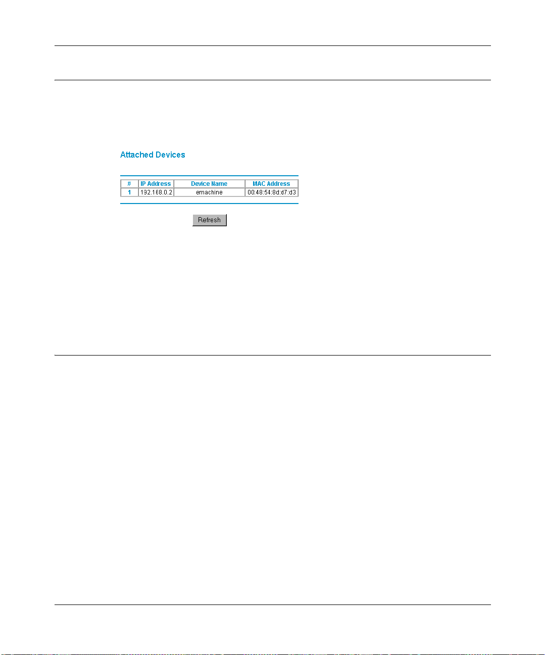
Reference Manual for the Model MR814 Wireless Router
Attached Devices
The Attached Device s men u contains a table of al l IP devices that the router has discovere d on the
local network. From the Main Menu of the browser interface, under the Maintenance heading,
select Attached Devices to view the table, shown in Figure 7-3
Figure 7-3. Attached Devices menu
For each device, the table shows the IP address, NetBIOS Host Name (if available), and Ethernet
MAC address. Note that if the router is rebooted, the table data is lost until the router rediscovers
the devices. To force the router to look for attached devices, click the Refresh button.
Router Softwa re Upg ra de
The routing software of the Model MR814 router is stored in FLASH memory, and can be
upgraded as new software is released by NETGEAR. Upgrade files can be downloaded from
Netgear's website. If the upgrade file is compressed (.ZIP file), you must first extract the binary
(.BIN) file before sending it to the router. The upgrade file can be sent to the router using your
browser.
Note: The Web browser used to upl oad n ew fi r mwa re i nt o t he Mode l MR814 r out er must support
HTTP uploads. NETGEAR recommends using Microsoft Internet Explorer 5.0 or Netscape
Navigator 4.7 or above.
7-4 Maintenance
Page 71
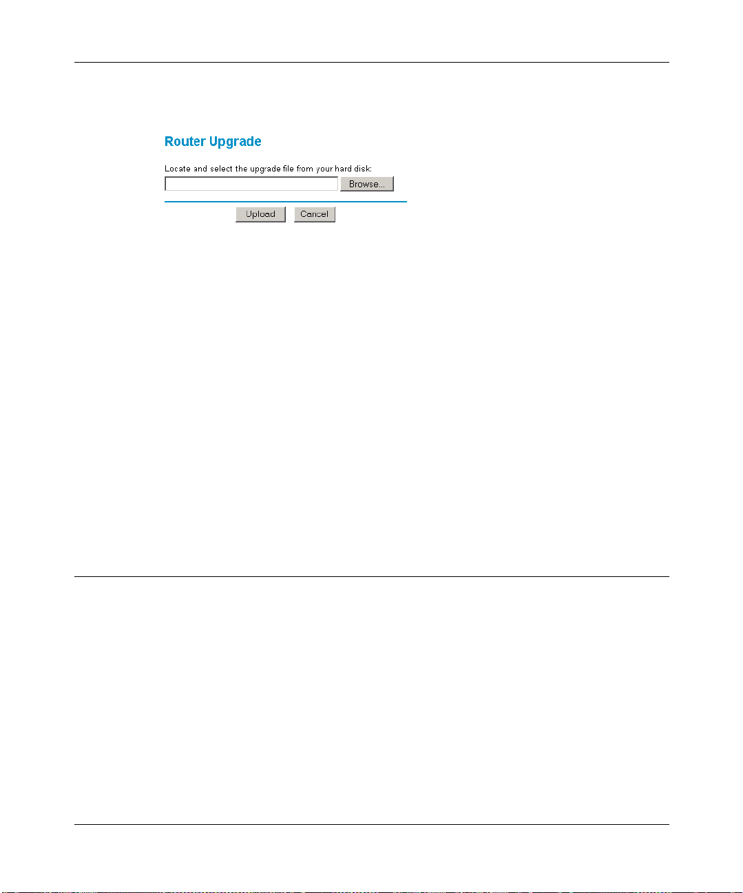
Reference Manual for the Model MR814 Wireless Router
From the Main Menu of the browser interface, under the Maintenance heading, select the Router
Upgrade heading to display the menu shown in Figure 7-4.
Figure 7-4. Router Upgrade menu
To upload new firmware:
1. Download a nd unzip the new software file from NETGEAR.
2. In the Router Upgrade menu, click the Browse button and browse to the locati on of the binary
(.BIN) upgrade file
3. Click Upload.
Note: When uploading software to the Model MR814 router, it is important not to i nterrupt the
Web browser by closing the window, clicking a link, or loading a new page. If the browser is
interrupted, it may corrupt the software. When the upload is complete, your router will
automatically restart. The upgrade process will typically take about one minute.
In some cases, you may need to reconfigure the router after upgrading.
Configuration File Settings Ma nagement
The configuration settings of the Model MR814 router are stored within the router in a
configuration file. This file can be saved (backed up) to a user’s PC, retrieved (restored) from the
user’s PC, or cleared to factory default settings.
Maintenance 7-5
Page 72
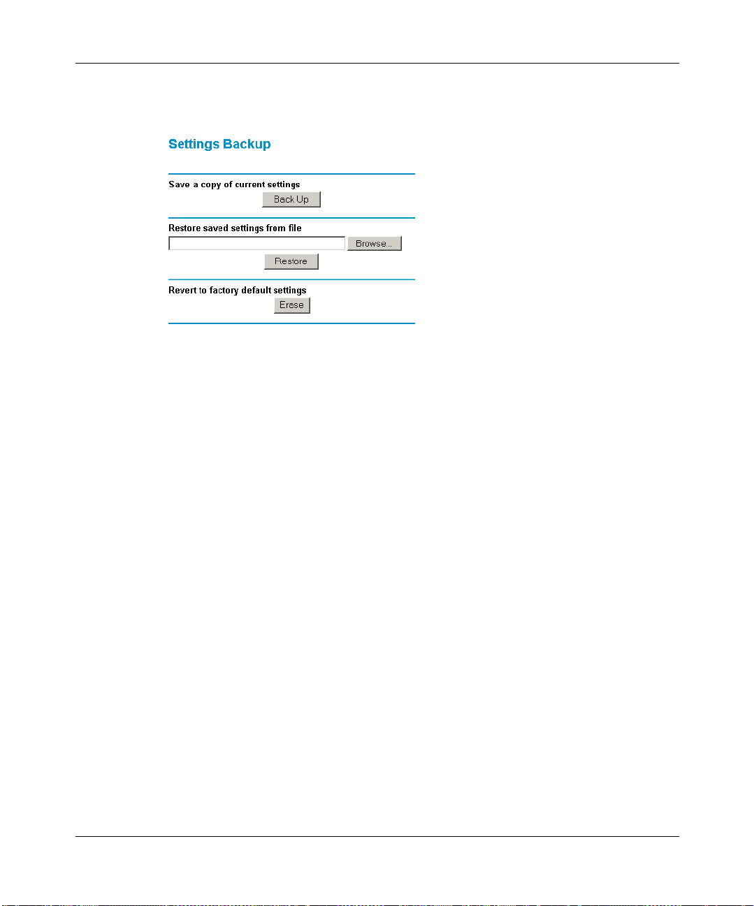
Reference Manual for the Model MR814 Wireless Router
From the Main Menu of the browser inter fa ce, und er the Main tenance heading, select the Set ti ngs
Backup heading to bring up the menu shown in Figure 7-5.
Figure 7-5. Settings Backup menu
Three options are available, and are described in the following sections.
Restore and Backup the Configuration
The Restore and Backup options in the Sett ings Bac kup menu al low you to save and retr ieve a fi le
containing your router’s configuration settings.
To save your settings, select the Backup tab. Click the Backup button. Your browser will extract
the configuration file from the router and will prompt you for a location on your PC to store the
file. You can give the file a meaningful name at this time, such as pacbell.cfg.
T o r estor e your set tings from a save d conf igura tion file , ente r the f ull path t o the fil e on your PC or
click the Browse button to browse to the file. When you have loca ted it, click the Rest ore button to
send the file to the router. The router will then reboot automatically.
Erase the Configuration
It is sometimes desirable to restore the router to a known blank condition. This can be done by
using the Erase function, which will restore all factory settings. After an erase, the router's
password will be password, the LAN IP address will be 192.1 68.0.1, and th e router's DHCP clie nt
will be enabled.
7-6 Maintenance
Page 73
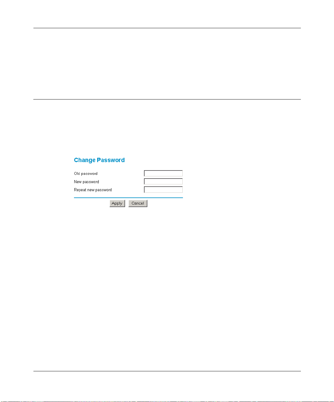
Reference Manual for the Model MR814 Wireless Router
To erase the configuration, click the Erase button.
To restore the factory default configuration settings without knowing the login password or IP
address, you must use the Default Reset button on the rear panel of the router. See “Using the
Default Reset button“ on page 9-8.
Changing the Configuration Password
The default password for the router’s Web Configuration Manager is password. Netgear
recommends that you change this password to a more secure password.
From the Main Menu of the browser interface, under the Maintenance heading, select Set
Password to bring up the menu shown in Figure 7-6.
Figure 7-6. Set Password menu
T o change the password, first enter the old password, and then enter the new password twice. Click
Apply.
Maintenance 7-7
Page 74

Reference Manual for the Model MR814 Wireless Router
7-8 Maintenance
Page 75

Chapter 8
Advanced Configuration of the Router
This chapter describes how to configure the advanced features of your Model MR814 Wireless
Router. These feature s can be fo und under th e Advanced he ading in t he Main Menu of the browser
interface.
Advanced Configuration of the Router 8-1
Page 76

Reference Manual for the Model MR814 Wireless Router
Configuring for Port Forwarding to Local Serve rs
Although the router ca use s your ent ir e lo cal network to appear as a single machine to the Internet,
you can make a local server (for exampl e, a web server or ga me server) vis ible and avai lable to the
Internet. This is done using the Port Forwarding menu. From the Main Menu of the browser
interface, under Advanced, click on Port Forwarding to view the port forwarding menu, shown in
Figure 8-1
Figure 8-1. Port Forwarding Menu.
Note: Some residential broadband ISP accounts do not allow you to run any server
processes (such as a Web or FTP server) from your location. Your ISP may periodically
check for servers and may suspend your account if it discovers any active services at
your location. If you are unsure, refer to the Acceptable Use Policy of your ISP.
Use the Port Forwardi ng me nu to config ure t he rou ter t o for ward i ncoming p rotoc ols t o comp uters
on your local network. In addition to servers for specific applications, you can also specify a
Default DMZ Server to which all other incoming protocols are forwarded. The DMZ Server is
configured in the Security Menu.
Before starting, you'l l ne ed t o determine which type of serv ic e, app li cat i on or game you'll provide
and the IP address of the computer that will provide each service. Be sure the computer’s IP
address never changes. To configure port forwarding to a local server:
1. From the Service & Game box, select the service that you will host on your network. If the
service does not appear in the list, refer to the following section, “Add a Custom Service”.
2. Enter the IP address of the local server in the corresponding Server IP Address box.
3. Click the Add button.
8-2 Advanced Configuration of the Router
Page 77

Reference Manual for the Model MR814 Wireless Router
Add a Custom Service
To define a service, game or application that does not appear in the Services & Games list, you
must determine what port numbers are used by the service. For this information, you may need to
contact the manufacturer of the program that you wish to use. For more information on service
ports, see “Block Services“ on page 6-4. When you have the port number information, follow
these steps:
1. Click the Add Custom Service button.
2. Enter the first port number in an unused Start Port box.
3. To forward only one port, enter it again in the End Port box. To specify a range of ports, enter
the last port to be forwarded in the End Port box.
4. Enter the IP address of the local server in the corresponding Server IP Address box.
5. Type a name for the service.
6. Click Apply at the bottom of the menu.
Edit or Delete a Port Forwarding Entry
To edit or delete a Port Forwarding entry, follow these steps.
1. In the table, select the button next to the service name.
2. Click Edit or Delete.
Local Web and FTP Server Example
If a local PC with a pr ivate IP addr ess of 192.168.0 .33 a cts as a Web and FTP server, config ure th e
Ports menu to forward HTTP (port 80) and FTP (port 21) to local address 192.168.0.33
In order for a remote user to access this server from the Internet, the remote user must know the IP
address that has been assigned by your ISP. If this address is 172.16 .1.23 , for exa mp le, an Internet
user can access your Web server by directing the browser to http://172.16.1.23. The assigned IP
address can be found in the Maintenance Status Menu, where it is shown as the WAN IP Address.
Some consid erations for this applicat ion are:
• If your account’s IP address is assigned dynamically by your ISP, the IP address may change
periodically as the DHCP lease expires.
Advanced Configuration of the Router 8-3
Page 78

Reference Manual for the Model MR814 Wireless Router
• If the IP address of the local PC is assign ed by DHCP, it may change when the PC is reboot ed.
T o avoid this, use the Address Reservations feature in the LAN IP menu to make sure the local
PC always receives the same IP address.
• Local PCs must access the local server by its local LAN address (192.168.0.33 in this
example). Attempts by local PCs to acc ess the server using the external IP address
(172.16.1.23 in this example) will fail.
Setting Up Multiple Computers for Half Life, KALI or Quake III
To set up an additional computer to play Half Life, KALI or Quake III:
1. Click the button of an unused port in the table.
2. Select the game again from the Services/Games list.
3. Change the beginning port number in the Start Port box.
For these games, use the supplied number in the default listing and add +1 for each additional
computer. For example, if you've already configured one computer to play Hexen II (using
port 26900), the second computer's port number would be 26901, and the third computer
would be 26902.
4. Type the same port number in the End Port box that you typed in the Start Port box.
5. Type the IP address of the additional computer in the Server IP Address box.
6. Click Apply.
Some online games and videoconferencing applications are incompatible with NAT. The Model
MR814 router is programmed to recognize some of these applications and to work properly with
them, but there are other application s that may not function well. In some cases, one loca l PC can
run the applicati on prope rly i f tha t PC’s IP address is entered as the defaul t in th e PORTS Menu. If
one local PC acts as a game or videoconference host, enter its IP address as the default.
Security
The security area lets you configure a DMZ server for hosting specific Internet services without
sacrificing unauthorized access to your private network. Also, in this area, you can enable
the Internet port to respond to PING requests. Setting up these features is described below
8-4 Advanced Configuration of the Router
Page 79

Reference Manual for the Model MR814 Wireless Router
DMZ Server
Incoming traffic from the Internet is normally discarded by the router unless the traffic is a
response to one of your local computers or a service that you have configured in the Port
Forwarding menu. Instead of discardi ng this t raf fi c, you can have it forwar ded to one computer on
your network. This computer is called the Default DMZ Server.
The Default DMZ Server feature is helpful whe n using some online game s and videoconferencing
applications that are in compatible wit h NAT . The route r is progr ammed to rec ognize some o f these
applications and to wor k p roperly with t hem, but th ere are other appli cati ons t hat may not funct ion
well. In some cases, one local PC can r un the appl ication properly i f that PC’s IP addr ess is ent ered
as the Default DMZ Serve r.
The Security menu, shown in Figure 8-2, allows the configuration of a Default DMZ Server.
Figure 8-2. Security menu.
Note: For security, you should avoid using the Default DMZ Server feature. When a
computer is design ated as the De fault DMZ Ser ver , it lose s much of the protect ion of th e
router, and is expo sed t o many e xploit s fr om the Inter net. I f compr omised, the c omputer
can be used to attack your network.
To assign a computer or server to be a Default DMZ server:
1. Click Default DMZ Server.
2. Type the IP address for that server.
3. Click Apply.
Advanced Configuration of the Router 8-5
Page 80

Reference Manual for the Model MR814 Wireless Router
Respond to Ping on Internet WAN Port
If you want the router to respond to a 'ping' from the Internet, click the ‘Respond to Ping on
Internet WAN Port’ check box. This should only be used as a diagnostic tool, since it allows your
router to be discovered. Don't check this box unless you have a specific reason to do so.
Dynamic DNS
If your network has a permanently assigned IP address, you can register a domain name and have
that name linked with your IP address by public Domain Name Servers (DNS). However, if your
Internet account uses a dynamically assigned IP address, you will not know in advance what your
IP address will be, and the address can change frequently. In this case, you can use a commercial
dynamic DNS service, who will allow you to register your domain to their IP address, and will
forward traffic directed at your domain to your frequently-changing IP address.
The router contains a client that can connect to many popular dynamic DNS services. You can
select one of these services and obtain an account with them. Then, whenever your ISP-assigned
IP address changes, your router will automatically contact your dynamic DNS service provider,
log in to your account, and register your new IP address.
From the Main Menu of the browser interface, under Advanced, click on Dynamic DNS. To
configure Dynamic DNS:
1. Access the website of one of the dynamic DNS service providers whose names appear in the
‘Select Service Provider’ box, and register for an account.
For example, for dyndns.org, go to www.dyndns.org.
2. Select the Use a dynamic DNS service check box.
3. Select the name of your dynamic DNS Service Provider.
4. Type the Host Name that your dynamic DNS service provider gave you.
The dynamic DNS service provider may call this the domain name.
5. Type the User Name for your dynamic DNS account.
6. Type the Password (or key) for your dynamic DNS account.
7. If your dynamic DNS provider allows the use of wildcards in resolving your URL, you may
select the Use wildcards check box to activate this feature.
For example, the wildcard feature will cause *.yourhost.dyndns.org to be aliased to the same
IP address as yourhost.dyndns.org
8-6 Advanced Configuration of the Router
Page 81
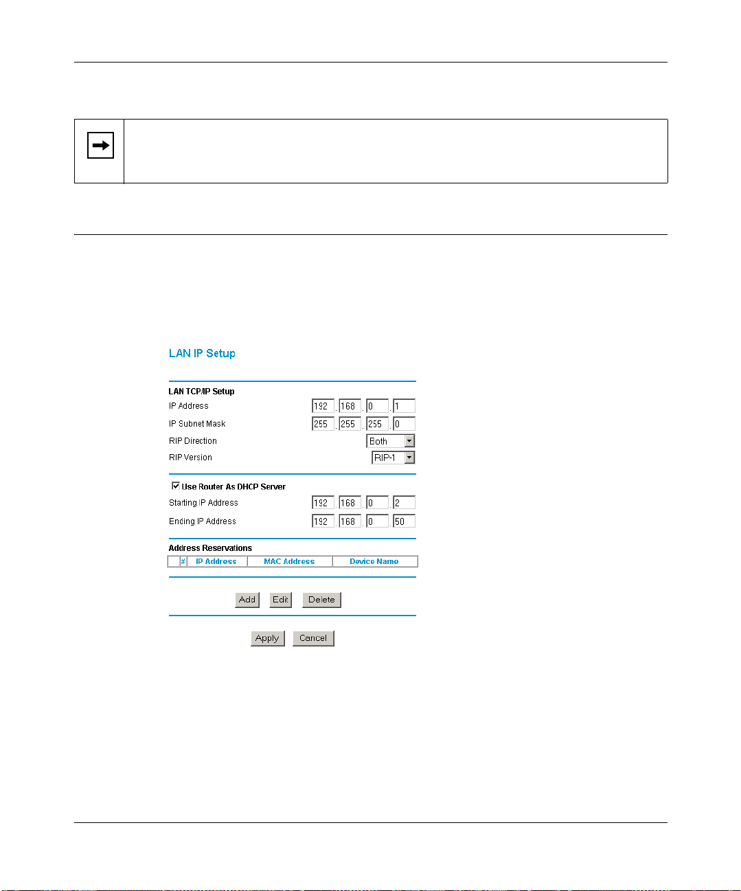
Reference Manual for the Model MR814 Wireless Router
8.
Click Apply to save your configuration.
Note: If your ISP assigns a private WAN IP address (such as 192.168.x.x or 10.x.x.x),
the dynamic DNS service will not work because private addresses will not be routed on
the Internet.
LAN IP Setup
The second feature category under the Advanced heading is LAN IP Setup. This menu allows
configuration of LAN IP services such as DHCP and RIP. From the Main Menu of the browser
interface, under Advanced, click on LAN IP Setup to view the LAN IP Setup menu, shown in
Figure 8-3
Figure 8-3. LAN IP Setup Menu
LAN TCP/IP Setup
The router is shipped preconfigured to use private IP addresses on the LAN side, and to act.as a
DHCP server. The router’s default LAN IP configuration is:
Advanced Configuration of the Router 8-7
Page 82
Reference Manual for the Model MR814 Wireless Router
• LAN IP addresses—192.168.0.1
• Subnet mask—255.255.255.0
These addresses ar e p art of the IETF-designated private address range fo r use in private networks,
and should be suit able in mos t appl ic ations . If yo ur net work has a requ irement to us e a different IP
addressing scheme, you can make those changes in this menu.
The LAN IP pa rameters are:
• IP Address
This is the LAN IP address of the router.
• IP Subnet Mask
This is the LAN Sub net Mask of the rou ter. Comb ined with the IP address, the IP Sub net Mask
allows a device to know which other addresses are local to it, and which must be reached
through a gateway or router.
• RIP Direction
RIP (Router Informat ion Prot ocol) allows a router to exc hange routing information wi th other
routers. The RIP Direction selection controls how the router sends and receives RIP packets.
Both is the default.
— When set to Both or Out Only, the router will broadcast its routing table periodically.
— When set to Both or In On ly, it will incorporate the RIP information that it receives.
— When set to None, it will not send any RIP packets and will ignore any RIP packets
received.
• RIP Version
This controls the fo rm at and the broadcasting met hod of the RIP packets that the ro uter sends.
(It recognizes both formats when receiving.) By default, this is set for RIP-1.
— RIP-1 is universally sup por ted. RIP-1 is probably adequate for most networks, unless you
have an unusual network setup.
— RIP-2 carries more information. RIP-2B uses subnet broadcasting..
Note: If you change the LAN IP address of the router while connected through the
browser, you will be disconnected. You must then open a new connection to the new IP
address and log in again.
8-8 Advanced Configuration of the Router
Page 83

Reference Manual for the Model MR814 Wireless Router
DHCP
By default, the router will function as a DHCP (Dynamic Host Configuration Protocol) server,
allowing it to assign IP, DNS server, and default gateway addresses to all computers connected to
the router's LAN. The assigned default gateway address is t he LAN address of the rout er. IP
addresses will be assigned to the attached PCs from a pool of addresses specified in this menu.
Each pool address is tested before it is assigned to avoid duplicate addresses on the LAN.
For most applications, the def ault DHCP and TCP/I P settin gs of the ro uter are satisfa ctory. See “IP
Configuration by DHCP” on page B-10 fo r an explanat ion of DHCP and infor mation about how to
assign IP addresses for your network.
Use Router as DHCP server
If another device on your network will be the DHCP server, or if you will manually configure the
network settings of all of your computers, clear the ‘Use router as DHCP server’ check box.
Otherwise, leave it checked.
Specify the pool of IP addresses to be assigned by setting the Starting IP Address and Ending IP
Address. These addresses should be part of the same IP address subnet as the router’s LAN IP
address. Using th e d efa ul t addressing scheme, you should define a range be twee n 192.168.0.2 and
192.168.0.253, although you may wish to save part of the range for devices with fixed addresses.
The router will deliver the following parameters to any LAN device that requests DHCP:
• An IP Address from the range you have defined
• Subnet Mask
• Gateway IP Address (the router’s LAN IP address)
• Primary DNS Server (if you entered a Primary DNS address in the Basic Settings menu;
otherwise , the router’s LAN IP ad dress)
• Secondary DNS Server (if you entered a Secondary DNS address in the Basic Settings menu
Address Reservations
When you specify a reserved IP address for a PC on the LAN, that PC will always receive the
same IP address each time it access the router’s DHCP server. Reserved IP addresses should be
assigned to servers that require permanent IP settings.
To reserve an IP address:
Advanced Configuration of the Router 8-9
Page 84
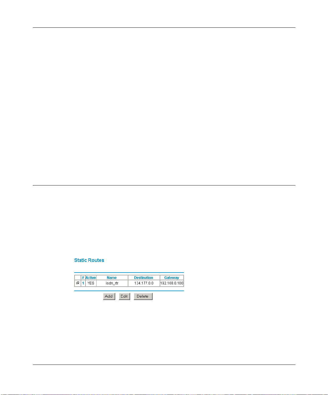
Reference Manual for the Model MR814 Wireless Router
1.
Click the Add button.
2. In the IP Address box, type the IP address to assign to the PC or server.
(choose an IP address from the router’s LAN subnet, such as 192.168.0.X)
3. Type the MAC Address of the PC or server.
(Tip: If the PC is already present on your network, you can copy its MAC address from the
Attached Devices menu and paste it here.)
4. Click Apply to enter the reserved address into the table.
Note: The reserved address will not be assigned until the next time the PC contacts the router's
DHCP server. Reboot the PC or access its IP configuration and force a DHCP release and renew.
To edit or delete a reserved address entry:
1. Click the button next to the reserved address you want to edit or delete.
2. Click Edit or Delete.
Static Routes
Static Routes provide additional routing information to your router. Under normal circumstances,
the router has adequate routing information after it has been configured for Internet access, and
you do not need to configure additional static routes. You must configure static routes only for
unusual cases such as multiple routers or multiple IP subnets located on your network.
From the Main Menu of the browser inter face , under Advanc ed, click on S ta tic Routes t o view the
Static Route menu, shown in Figure 8-4.
Figure 8-4. Static Route Summary Table
To add or edit a Static Route:
8-10 Advanced Configuration of the Router
Page 85
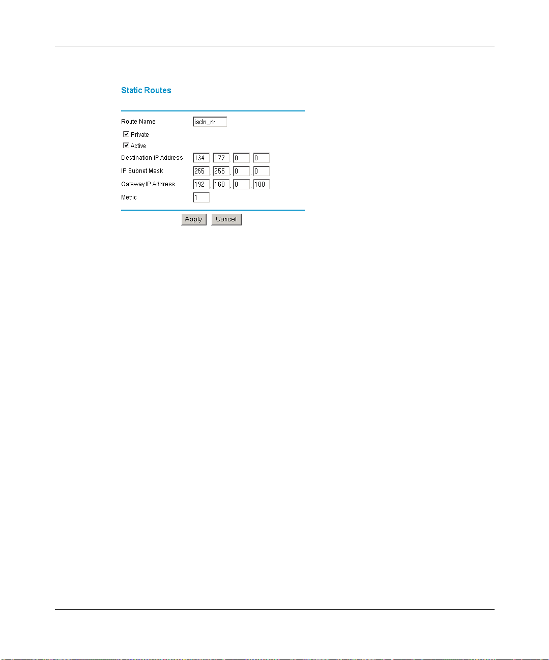
Reference Manual for the Model MR814 Wireless Router
1.
Click the Add button to open the Add/Edit Menu, shown in Figure 8-5.
Figure 8-5. Static Route Entry and Edit Menu
2.
Type a route name for this static route in the Route Name box under the table.
(This is for identification purpose only.)
3. Select Private if you want to lim it access to th e LAN only. The static route wil l not be reported
in RIP.
4. Select Active to make this route effective.
5. Type the Destination IP Address of the final destination.
6. Type the IP Subnet Mask for this destination.
If the destination is a single host, type 255.255.255.255.
7. T ype the Gat eway IP Address , which must be a router on th e same LAN segment as t he router.
8. Type a number between 1 and 15 as the Metric value.
This represents the number of routers between your network and the destination. Usually, a
setting of 2 or 3 works, but if this is a direct connection, set it to 1.
9. Click Apply to have the static route entered into the table.
Static Route Example
As an example of when a static route is needed, consider the following case:
• Your primary Internet access is through a cable modem to an ISP.
Advanced Configuration of the Router 8-11
Page 86
Reference Manual for the Model MR814 Wireless Router
• You have an ISDN router on your home network for connecting to the company where
you are employed. This router’s address on your LAN is 192.168.0.100.
• Your company’s network is 134.177.0.0.
When you first configur ed your r outer , two impl icit stat ic rou tes wer e crea ted. A defaul t rout e was
created with your ISP as the gateway, and a second static route was created to your local network
for all 192.168.0.x addresses. With this configuration, if you attempt to access a device on the
134.177.0.0 network, your router will forward your request to the ISP. The ISP forwards your
request to the company where you are employed, and the request will likely be denied by the
company’s firewall.
In this case you must define a static route, telling your router that 134.177.0.0 should be accessed
through the ISDN router at 192.168.0.100. The static route would look like Figure 8-5.
In this example:
• The Destination IP Address and IP Subnet Mask fields specify that this static route applies to
all 134.177.x.x addresses.
• The Gateway IP Address fields specifies t hat all traffic for these addresses should be
forwarded to the ISDN router at 192.168.0.100.
• A Metric value of 1 will work since the ISDN router is on the LAN.
• Private is selected only as a precautionary security measure in case RIP is activated.
Remote Management
Using the Remote Management page, you can allow a user or users on the Internet to configure,
upgrade and check the status of your Model MR814 router.
Note: Be sure to change the router's default configuration password to a very secure
password. The ideal password should contain no dictionary words from any language,
and should be a mixture of letters (both upper and lower case), numbers, and symbols.
Your password can be up to 30 characters.
To configure your router for Remote Management:
1. Select the Turn Remote Management On check box.
8-12 Advanced Configuration of the Router
Page 87

Reference Manual for the Model MR814 Wireless Router
2.
Specify what external addresses will be allowed to access the router’s remote management.
For security, NETGEAR recommends that you restrict access to as few external IP addresses
as practical.
a. To allow access from any IP address on the Internet, select Everyone.
b. To allow access from a range of IP addresses on the Internet, select IP address range.
Enter a beginning and ending IP address to define the allowed range.
c. To allow access from a single IP address on the Internet, select Only this PC.
Enter the IP address that will be allowed access.
3. Specify the Port Number that will be used for accessing the management interface.
Web browser access normally uses the standard HTTP service port 80. For greater security,
you can change the remote management web interface to a custom port by entering that
number in the box provided. Choose a number between 1024 and 65535, but do not use the
number of any common service port. The default is 8080, which is a common alternate for
HTTP.
4. Click Apply to have your changes take effect.
When accessing your router from the Internet, you will type your router's WAN IP address into
your browser's Address (in IE) or Location (in Netscape) box, followed by a colon (:) and the
custom port number. For example, if your external address is 134.177.0.123 and you use port
number 8080, enter in your browser:
http://134.177.0.123:8080
Advanced Configuration of the Router 8-13
Page 88

Reference Manual for the Model MR814 Wireless Router
8-14 Advanced Configuration of the Router
Page 89

Chapter 9
Troubleshooting
This chapter gives information about troubleshooting your Model MR814 Wireless Router. After
each problem description, instructions are provided to help you diagnose and solve the problem.
For the common problems listed, go to the section indicated.
• Is the router on?
• Have I connected the router correctly?
Go to “Basic Functioning“ on page 9-1.
• I can’t access the router’s configuration with my browser.
Go to “Troubleshooting the Web Configuration Interface“ on page 9-3.
• I’ve configured the router but I can’t access the Internet.
Go to “Troubleshooting the ISP Connection“ on page 9-4.
• I can’t remember the router’s configuration password.
• I want to clear the configuration and start over again.
Go to “Restoring the Default Configuration and Password“ on page 9-7.
Basic Functioning
After you turn on power to the router, the following sequence of events should occur:
1. When power is first applied, verify that the Power LED is on.
2. Verify that the Test LED lights within a few seconds, indicating that the self-test
procedure is running.
3. After approximately 10 seconds, verify that:
a. The Test LED is not lit.
Troubleshooting 9-1
Page 90

Reference Manual for the Model MR814 Wireless Router
b. The LAN port LEDs are lit for any local ports that are connected.
c. The WAN port LED is lit.
If a port’s LED is lit, a link has been established to the connected device. If a LAN port is
connected to a 100 Mbps de vice, veri fy that th e port’s LED is green. If the port is 10 Mbps, the
LED will be amber.
If any of these conditions does not occur, refer to the appropriate following section.
Power LED Not On
If the Power and other LEDs are off when your router is turned on:
• Make sure that the power cord is properly connected to your router and that the power supply
adapter is properly connected to a functioning power outlet.
• Check that you are using the 12 V DC power adapter supplied by NETGEAR for this product.
If the error persists, you have a hardware problem and should contact technical support.
Test LED Never Turns On or Test LED Stays On
When the router is turned on, the Test LED turns on for ab out 10 seconds and then tu rns off. If the
Test LED does not turn on, or if it stays on, there is a fault within the router.
If you experience problems with the Test LED:
• Cycle the power to see if the router recovers and the LED blinks for the correct amount of
time.
If all LEDs including the Test LED are still on one minute after po wer up:
• Cycle the power to see if the router recovers.
• Clear the router’s configuration to factory defaults. This will set the router’s IP address to
192.168.0.1. This procedure is explained in “Using the Default Reset button“ on page 9-8.
If the error persists, you might have a hardware problem and should contact technical support.
LAN or WAN Port LEDs Not On
If either the LAN LEDs or WAN LED do not light when the Ethernet connection is made, check
the following:
9-2 Troubleshooting
Page 91

Reference Manual for the Model MR814 Wireless Router
• Make sure that the Ethernet cable connections are secure at the router and at the hub or
workstation.
• Make sure that power is turned on to the connected hub or workstation.
• Be sure you are using the correct cable:
— When connecting the router’s WAN port to a cable or DSL modem, use the cable that was
supplied with the cable or DSL modem. This cable could be a standard straight-through
Ethernet cable or an Ethernet crossover cable.
Troubleshooting the Web Configuration Interf ace
If you are unable to access the router’s Web Configuration interface from a PC on your local
network, check the following:
• If you are using an Ethernet -conne cted P C, che ck the Ether net c onnect ion betwee n the PC and
the router as described in the previous section.
• If you are using a wireless-connected PC, that th e SSID and WEP setti ngs are the same for t he
router and PC. The router’s default settings are: SSID is Wireless and WEP is disabled.
• Make sure your PC’s IP address is on the same subnet as the router. If you are using the
recommended addressing scheme, your PC’s address should be in the range of 192.168.0.2 to
192.168.0.254. Refer to “Verifying TCP/IP Properties“ on page 3-5 or “Verifying TCP/IP
Properties for Macintosh Computers“ on page 3-8 to find your PC’s IP address. Follow the
instructions in Chapter 3 to configure your PC.
Note: If your PC’s IP address is shown as 169.254.x.x:
Recent versions of Windows and MacOS will generate and assign an IP address if the
computer cannot reach a DHCP server. These auto-generated addresses are in the range of
169.254.x.x. If your IP address is in this ran ge, check th e connect ion fro m the PC to the rout er
and reboot your PC.
• If your router’s IP address has been changed and you don’t know the current IP address, clear
the router’s configuration to factory defaults. This will set the router’s IP address to
192.168.0.1. This procedure is explained in “Using the Default Reset button“ on page 9-8.
• Make sure your browser has Java, JavaScript, or ActiveX enabled. If you are using Internet
Explorer, click Refresh to be sure the Java applet is loaded.
• Try quitting the browser and launching it again.
Troubleshooting 9-3
Page 92

Reference Manual for the Model MR814 Wireless Router
• Make sure you are using the correct login information. The factory default login name is
admin and the password is password. Make sure that CAPS LOCK is off when entering this
information.
If the router does not save changes you have made in the Web Configuration Interface, check the
following:
• When entering configuration settings, be sure to click the APPLY button before moving to
another menu or tab, or your changes are lost.
• Click the Refresh or Reload button in the Web browser. The changes may have occurred, but
the Web browser may be caching the old configuration.
Troubleshooting the ISP Connection
If your router is unable to acces s the Inte rnet, you sho uld first det ermine whether the router is able
to obtain a WAN IP address from the ISP. Unless you have been assigned a static IP address, your
router must request an IP address from the ISP. You can determine whether the request was
successful using the Web Configuration Manager.
To check the WAN IP address:
1. Launch your browser and select an external site such as www.netgear.com
2. Access the Main Menu of the router’s configuration at http://192.168.0.1
3. Under the Maintenance heading, select Router Status
4. Check that an IP address is shown for the WAN Port
If 0.0.0.0 is shown, your router has not obtained an IP address from your ISP.
If your router is unable to obtain an IP address from the ISP, you may need to force your cable or
DSL modem to recognize your new router by performing the following procedure:
1. Turn off power to the cable or DSL modem.
2. Turn off power to your router.
3. Wait five minutes and reapply power to the cable or DSL modem.
4. When the modem’s LEDs indicate that it has reacquired sync with the ISP, reapply power to
your router.
If your router is still unable to obtain an IP address from the ISP, the problem may be one of the
following:
9-4 Troubleshooting
Page 93

Reference Manual for the Model MR814 Wireless Router
• Your ISP may require a login program.
Ask your ISP whether they require PPP over Ethernet (PPPoE) or some other type of login.
• If your ISP requires a login, you may have incorrectly set the login name and password.
• Your ISP may check for your PC's host name.
Assign the PC Host Name of your ISP account as the Account Name in the Basic Settings
menu.
• Your ISP only allows one Ethernet MAC address to connect to Internet, and may check for
your PC’s MAC address. In this case:
Inform your ISP that you have bought a new network device, and ask them to use the router’s
MAC address.
OR
Configure your route r to spoo f your PC’s MAC address. This can be done in the Bas ic Setti ngs
menu. Refe r to “Configuring Manually“ on page 4-8.
If your router can obtain an IP address, but your PC is unable to load any web pages from the
Internet:
• Your PC may not recognize any DNS server addresses.
A DNS server is a host on the Intern et that tr ans la te s Int er net names (su ch as www addres ses )
to numeric IP addresses. Typically your ISP will provide the addresses of one or two DNS
servers for your use. If you entered a DNS address during the router’s configuration, reboot
your PC and verify the DNS address as described in “Verifying TCP/IP Properties“ on page
3-5. Alternatively, you may configure your PC manually with DNS addresses, as explained in
your operating system documenta ti on.
• Your PC may not have the router configured as its TCP/IP gateway.
If your PC obtains its information from the router by DHCP, reboot the PC and verify the
gateway address as described in “Verifying TCP/IP Properties“ on page 3-5.
Troubleshooting a TCP/IP Network Using the Ping Utility
Most TCP/IP terminal devices and routers contain a ping utility that sends an echo request packet
to the designated device. The device then responds with an echo reply. Troubleshooting a TCP/IP
network is made very easy by using the ping utility in your PC or workstation.
Troubleshooting 9-5
Page 94

Reference Manual for the Model MR814 Wireless Router
Testing the LAN Path to Your Router
You can ping the router from your PC to verify that the LAN pa th to your router is set up correctly.
To ping the router from a PC running Windows 95 or later:
1. From the Windows toolbar, click on the Start button and select Run.
2. In the field provided, type Ping followed by the IP address of the router, as in this example:
ping 192.168.0.1
3. Click on OK.
You should see a message like this one:
Pinging <IP address> with 32 bytes of data
If the path is working, you s ee this messag e:
Reply from < IP address >: bytes=32 time=NN ms TTL=xxx
If the path is not working, y ou see this mess age:
Request timed out
If the path is not functioning correctly, you could have one of the following problems:
• Wrong physical connections
— Make sure the LAN port LED is on. If the LED is off, follow the instructions in “LAN
or WAN Port LEDs Not On” on page 9-2.
— Check that the corresponding Link LEDs are on for your network interface card and
for the hub ports (if any) that are connected to your workstation and router.
• Wrong network configuration
— Verify that the Ethernet card driver software and TCP/I P software are both install ed
and configured on your PC or workstation.
— Verify that the IP address for your router and your works tati on are cor rect and that the
addresses are on the same subnet.
9-6 Troubleshooting
Page 95

Reference Manual for the Model MR814 Wireless Router
Testing the Path from Your PC to a Remote Device
After verifying that the LAN path works correctly, test the path from your PC to a remote device.
From the Windows run menu, type:
PING -n 10 <IP address>
where <IP address> is the IP address of a remote device such as your ISP’s DNS server.
If the path is functioning correctly, replies as in the previous section are displayed. If you do not
receive replies:
— Check that your PC has t he IP ad dress of y our router listed as the def ault gate way. If the IP
configuration of yo ur PC is as signed by DHCP, this information wil l not be vis ible in your
PC’ s Networ k Control Panel. Verify that the IP add ress of the ro ute r is l isted as the d efaul t
gateway as described in “Verifying TCP/IP Properties“ on page 3-5.
— Check to see that the network address of your PC (the portion of the IP address specified
by the netmask) is different from the network address of the remote device.
— Check th at your cable or DSL modem is connec ted and functioning.
— If your ISP assigned a ho st name t o your PC, e nter t hat ho st name a s the Acc ount Name i n
the Basic Settings menu.
— Your ISP could b e reject in g the Ethern et MAC a ddress es of al l but one of yo ur PCs. Man y
broadband ISPs restrict access by only allowing traffic from the MAC address of your
broadband modem, but some ISPs additionally restrict access to the MAC address of a
single PC connected to that modem. If this is the case, you must configure your router to
“clone” or “spoof” the MAC address from the authorized PC. Refer to “Configuring
Manually“ on page 4-8.
Restoring the Default Configuration and Passwor d
This section explains how to restore the factory default configuration settings, changing the
router’s admin istrati on passwor d to password and the IP address to 192. 168.0.1. You can erase the
current configuration and restore factory defaults in two ways:
• Use the Erase function of the Web Configuration Manager (see “Erase the Configuration“ on
page 6-5).
• Use the Default Reset button on the rear panel of the router. Use this method for cases when
the administration password or IP address is not known.
Troubleshooting 9-7
Page 96

Reference Manual for the Model MR814 Wireless Router
Using the Default Reset button
To restore the factory default configuration settin gs wit hout k nowin g the ad mi ni st rat io n password
or IP address, you must use the Default Reset button on the rear panel of the router.
1. Press and hold the Default Reset button until the Test LED turns on (about 10 seconds).
2. Release the Default Reset button and wait for the router to reboot.
Problems with Date and Time
The E-Mail menu in the Content Filtering section displays the current date and time of day. The
Model MR814 router uses the Network Time Protocol (NTP) to obtain the current time from one
of several Networ k T ime Ser vers on the Int ernet. Ea ch entry in the log is s tamped wit h the da te and
time of day. Problems with the date and time function can include:
• Date shown is January 1, 2000
Cause: The router has not yet successfully reached a Network Time Server. Check that your
Internet access settings are configured correctly. If you have just completed configuring the
router, wait at least five minutes and check the date and time again.
• Time is off by one hour
Cause: The router does not automatically sense Daylight Savings Time. In the E-Mail menu,
check or uncheck the box marked “Adjust for Daylight Savings Time”.
9-8 Troubleshooting
Page 97

Appendix A
Technical Specifications
This appendix provides technical specifications for the Model MR814 Wireless Router.
Network Protocol and Standards Co mpatibility
Data and Routing Protocols: TCP/IP, RIP-1, RIP-2, DHCP
PPP over Ethernet (PPPoE)
Wireless Networking Specifications
Wireless Networking Standard 802.11b
Data rate 1, 2, 5.5, 11Mbps (Auto Rate Sensing)
Signal Frequency 2.4Ghz to 2.5Ghz Direct Sequence Spre ad Spect rum (DSSS)
Range Dep
ending on various environmental conditions,
maximums are:
Outdoor environment Indoor environment
1Mbps - 1650 ft (503 m) 1Mbps - 500 ft (152 m)
2Mbps - 1320 ft (402 m) 2Mbps - 400 ft (122 m)
5.5Mbps - 1155 ft (352 m) 5.5Mbps - 270 ft (82 m)
11Mbps - 835 ft (255 m) 11Mbps - 175 ft (53 m)
Encryption 64-bit (also called 40-bit) and 128-bit WEP data encryption
Technical Specifications A-1
Page 98

Reference Manual for the Model MR814 Wireless Router
Maximum number of wireless
hosts
Power Adapter
Limited by the amount of wi re less network traf f ic gene rated
by each node; typically 30 to 70 nodes.
North America: 120V, 60 Hz, input
United Kingdom, Australia: 240V, 50 Hz, input
Europe: 230V, 50 Hz, input
Japan: 100V, 50/60 Hz, input
All regions (output): 12 V DC @ 1.2A output, 30W maximum
Physical Specifications
Dimensions: 10" x 6.7" x 1.3" (without antenna)
255 mm x 169 mm x 34 mm
Weight: 1.4 lbs.
0.62 kg
Environmental Specifications
Operating temperature: 0° to 40° C (32º to 104º F)
Operating humidity: 90% maximum relative humidity, noncondensing
Electromagnetic Emissions
Meets requirements of: FCC Part 15 Class B
VCCI Class B
EN 55 022 (CISPR 22), Class B
Interface Specifications
LAN: 10BASE-T or 100BASE-Tx, RJ-45 (wired)
802.11b (wireless)
WAN: 10BASE-T, RJ-45
A-2 Technical Specifications
Page 99

Appendix B
Network and Routing Basics
This chapter provides an overview of IP networks, routing, and firewalls.
Basic Router Concepts
Large amounts of bandwidth can be provided easily and relatively inexpensively in a local area
network (LAN). However , provid ing high band width between a local network and the Inte rnet can
be very expensive. Because of this expense, Internet access is usually prov ided by a slower-speed
wide-area network (WAN) link such as a cable or DSL modem. In or der to mak e the bes t use of the
slower WAN link, a mechanism must be in place for sel ecting and transmit ting only t he data t raf fic
meant for the Internet. The function of selecting and forwarding this data is performed by a router.
What is a Router?
A router is a device that forwards traffic between networks based on network layer information in
the data and o n routing tables main tai ne d by the router. In these routing tables, a r out er builds up a
logical picture of the overall network by gathering and exchanging information with other routers
in the network. Using this information, the router chooses the best path for forwarding network
traffic.
Network and Routing Basics B-1
Page 100

Reference Manual for the Model MR814 Wireless Router
Routers vary in performance and scale, number of routing protocols supported, and types of
physical WAN connection they support. The Model MR814 Wireless Router is a small office
router that routes the IP protocol over a single-user broadband connection.
Routing Information Protocol
One of the protocols used by a router to b uil d a nd mai ntain a picture of the net w ork is the Routing
Information Protocol (RIP). Using RIP, routers periodically update one another and check for
changes to add to the routing table.
The Model MR814 router supports both the older RIP-1 and the newer RIP-2 protocols. Among
other improvements, RIP-2 supports subnet and multicast protocols. RIP is not required for most
home applications.
IP Addresses and the Internet
Because TCP/IP networks are interconnected across the world, every machine on the Internet must
have a unique address to make sur e that t ransmit ted dat a reache s the corr ect des tinat io n. Blocks of
addresses are assigned to organizations by the Internet Assigned Numbers Authority (IANA).
Individual users an d s ma ll organizations may ob tai n t heir addresses either fr om t he I ANA or fr om
an Internet service provider (ISP). You can contact IANA at www.iana.org.
The Internet Protocol (IP) uses a 32-bit address structure. The address is usually written in dot
notation (also called dotted-decimal notation), in which each group of eight bits is written in
decimal form, separated by decimal points.
For example, the following binary address:
11000011 00100010 00001100 00000111
is normally written as:
195.34.12.7
The latter version is easier to remember and easier to enter into your computer.
In addition, the 32 bits of the address are subdivided into two parts. The first part of the address
identifies the network, and the second part identifies the host node or station on the network. The
dividing point may vary depending on the address range and the application.
B-2 Network and Routing Basics
 Loading...