

Netgear JGSM7224 Reference Manual
ProSafe 24-Port Gigabit L2 Managed Switch JGSM7224
Reference Manual
350 East Plumeria Drive
San Jose, CA 95134
USA
November 2012
202-10922-02
v1.0

ProSafe 24-Port Gigabit L2 Managed Switch JGSM7224
Support
Thank you for choosing NETGEAR.
After installing your device, locate the serial number on the label of your product and use it to register your product
at https://my.netgear.com. You must register your product before you can
NETGEAR recommends registering your product through the NETGEAR
support, visit http://support.netgear.com.
Phone (US & Canada only): 1-888-NETGEAR.
Phone (Other Countries): Check the li
http://support.netgear.com/general/cont
NETGEAR recommends that you use only the official NETGEAR support resources.
st of phone numbers at
act/default.aspx.
use NETGEAR telephone support.
web site. For product updates and web
Trademarks
NETGEAR, the NETGEAR logo, and Connect with Innovation are trademarks and/or registered trademarks of
NETGEAR, Inc. and/or its subsidiaries in the United States and/or other countries. Information is subject to change
without notice. Other brand and product names are registered trademarks or trademarks of their respective
holders. © NETGEAR, Inc. All rights reserved.
Revision History
Publication
Part Number
202-10922-02 1.0 November 2012 • Thorough revision of the manual be
202-10922-01 1.0 November 2011 First publication
Version Publish Date Comments
many existing features was changed. Almost all figures were
replaced with new ones.
• Addition of the follow
- Registration
- System CPU Status
- DNS
- DiffServ
- Control of DHCP Snooping, IP Source Guard, and
Dynamic ARP Inspection
- File Management
ing new features:
cause the functioning of
2

Table of Contents
Chapter 1 Introduction and Getting Started
Package Contents . . . . . . . . . . . . . . . . . . . . . . . . . . . . . . . . . . . . . . . . . . . . 9
Maintenance and Support . . . . . . . . . . . . . . . . . . . . . . . . . . . . . . . . . . . . . . 9
Hardware Features . . . . . . . . . . . . . . . . . . . . . . . . . . . . . . . . . . . . . . . . . . . 9
Front Panel Ports and LEDs . . . . . . . . . . . . . . . . . . . . . . . . . . . . . . . . . 10
Rear Panel. . . . . . . . . . . . . . . . . . . . . . . . . . . . . . . . . . . . . . . . . . . . . . . 11
Bottom Panel with Product Label. . . . . . . . . . . . . . . . . . . . . . . . . . . . . . 12
Connect the Switch to the Network . . . . . . . . . . . . . . . . . . . . . . . . . . . . . . 12
Switch Management Methods . . . . . . . . . . . . . . . . . . . . . . . . . . . . . . . . . . 12
Configure Access to the Web Management Interface. . . . . . . . . . . . . . . . 13
Configure Access When the Switch Functions in DHCP Client
Mode without a DHCP Server . . . . . . . . . . . . . . . . . . . . . . . . . . . . . . . . 13
Configure Access When the Switch Functions in DHCP Client
Mode with a DHCP Server. . . . . . . . . . . . . . . . . . . . . . . . . . . . . . . . . . . 14
Configure the Switch with a Static IP Address. . . . . . . . . . . . . . . . . . . . 15
Log In to the Web Management Interface . . . . . . . . . . . . . . . . . . . . . . . . . 17
Web Management Interface Layout. . . . . . . . . . . . . . . . . . . . . . . . . . . . 18
Interface Naming Conventions . . . . . . . . . . . . . . . . . . . . . . . . . . . . . . . . . 20
Online Help . . . . . . . . . . . . . . . . . . . . . . . . . . . . . . . . . . . . . . . . . . . . . . . . 20
Support . . . . . . . . . . . . . . . . . . . . . . . . . . . . . . . . . . . . . . . . . . . . . . . . . 20
User Guide. . . . . . . . . . . . . . . . . . . . . . . . . . . . . . . . . . . . . . . . . . . . . . . 21
Registration . . . . . . . . . . . . . . . . . . . . . . . . . . . . . . . . . . . . . . . . . . . . . . . . 22
Chapter 2 Configuring the System
Management Settings . . . . . . . . . . . . . . . . . . . . . . . . . . . . . . . . . . . . . . . . 24
System Information . . . . . . . . . . . . . . . . .
System CPU Status. . . . . . . . . . . . . . . . . . . . . . . . . . . . . . . . . . . . . . . . 26
Green Ethernet Configuration . . . . . . . . . . . . . . . . . . . . . . . . . . . . . . . . 27
Denial of Service . . . . . . . . . . . . . . . . . . . . . . . . . . . . . . . . . . . . . . . . . . 28
Network Interface. . . . . . . . . . . . . . . . . . . . . . . . . . . . . . . . . . . . . . . . . . 29
Time. . . . . . . . . . . . . . . . . . . . . . . . . . . . . . . . . . . . . . . . . . . . . . . . . . . . 34
DNS. . . . . . . . . . . . . . . . . . . . . . . . . . . . . . . . . . . . . . . . . . . . . . . . . . . . 39
Services: DHCP Server and DHCP Layer 2 Relay . . . . . . . . . . . . . . . . . . 42
DHCP Server Configuration. . . . . . . . . . . . . . . . . . . . . . . . . . . . . . . . . . 43
DHCP Pool Configuration . . . . . . . . . . . . . . . . . . . . . . . . . . . . . . . . . . . 45
DHCP Pool Options. . . . . . . . . . . . . . . . . . . . . . . . . . . . . . . . . . . . . . . . 47
DHCP Server Statistics . . . . . . . . . . . . . . . . . . . . . . . . . . . . . . . . . . . . . 48
DHCP Bindings Information. . . . .
DHCP L2 Relay Global Configuration
Table of Contents | 3
. . . . . . . . . . . . . . . . . . . . . . . . . . . . . 49
. . . . . . . . . . . . . . . . . . . . . . . 25
. . . . . . . . . . . . . . . . . . . . . . . . . . 50

ProSafe 24-Port Gigabit L2 Managed Switch JGSM7224
DHCP L2 Relay Interface Configuration. . . . . . . . . . . . . . . . . . . . . . . . .51
DHCP L2 Relay Statistics. . . . . . . . . . . . . . . . . . . . . . . . . . . . . . . . . . . . 53
Simple Network Management Protocol . . . . . . . . . . . . . . . . . . . . . . . . . . . 55
Community Configuration. . . . . . . . . . . . . . . . . . . . . . . . . . . . . . . . . . . . 55
Trap Configuration . . . . . . . . . . . . . . . . . . . . . . . . . . . . . . . . . . . . . . . . . 57
Trap Flags . . . . . . . . . . . . . . . . . . . . . . . . . . . . . . . . . . . . . . . . . . . . . . .58
User Configuration . . . . . . . . . . . . . . . . . . . . . . . . . . . . . . . . . . . . . . . . . 59
Link Layer Discovery Protocol . . . . . . . . . . . . . . . . . . . . . . . . . . . . . . . . . .61
LLDP Basic Settings. . . . . . . . . . . . . . . . . . . . . . . . . . . . . . . . . . . . . . . .62
LLDP Interface Configuration. . . . . . . . . . . . . . . . . . . . . . . . . . . . . . . . .63
LLDP Basic TLV Configuration. . . . . . . . . . . . . . . . . . . . . . . . . . . . . . . .65
Local Device Information [LLDP] . . . . . . . . .
Remote Neighbor Information
LLDP Traffic . . . . . . . . . . . . . . . . . . . . . . . . . . . . . . . . . . . . . . . . . . . . . .70
Global Configuration [LLDP-MED] . . . . . . . . . . . . . . . . . . . . . . . . . . . . .71
Interface Configuration [LLDP-MED] . . . . . . . . . . . . . . . . . . . . . . . . . . .72
Local Device Information [LLDP-MED]. . . . . . .
Remote Device Information [LLDP-MED]. . . . . . . . . . . . . . . . . . . . . . . . 75
Remote Device Inventory [LLDP-MED] . . . . . . . . . . . . . . . . . . . . . . . . . 78
[LLDP] . . . . . . . . . . . . . . . . . . . . . . . . . . 69
. . . . . . . . . . . . . . . . . . . . .67
. . . . . . . . . . . . . . . . . . . 74
Chapter 3 Configuring Switching
VLANs . . . . . . . . . . . . . . . . . . . . . . . . . . . . . . . . . . . . . . . . . . . . . . . . . . . .80
VLAN Configuration . . . . . . . . . . . . . . . . . . . . . . . . . . . . . . . . . . . . . . . .81
VLAN Membership . . . . . . . . . . . . . . . . . . . . . . . . . . . . . . . . . . . . . . . . .83
VLAN Status. . . . . . . . . . . . . . . . . . . . . . . . . . . . . . . . . . . . . . . . . . . . . .84
Port PVID Configuration. . . . . . . . . . . . . . . . . . . . . . . . . . . . . . . . . . . . .85
MAC Based VLAN . . . . . . . . . . . . . . . . . . . . . . . . . . . . . . . . . . . . . . . . .87
IP Subnet Based VLAN . . . . . . . . . . . . . . . . . . . . . . . . . . . . . . . . . . . . .88
Port DVLAN Configuration . . . . . . . . . . . . . . . . . . . . . . . . . . . . . . . . . . . 90
Voice VLAN . . . . . . . . . . . . . . . . . . . . . . . . . . . . . . . . . . . . . . . . . . . . . . . . 91
Properties. . . . . . . . . . . . . . . . . . . . . . . . . . . . . . . . . . . . . . . . . . . . . . . .92
Port Settings. . . . . . . . . . . . . . . . . . . . . . . . . . . . . . . . . . . . . . . . . . . . . .93
OUI. . . . . . . . . . . . . . . . . . . . . . . . . . . . . . . . . . . . . . . . . . . . . . . . . . . . .94
Spanning Tree Protocol . . . . . . . . . . . . . . . . . . . . . . . . . . . . . . . . . . . . . . .96
STP Configuration . . . . . . . . . . . . . . . . . . . . . . . . . . . . . . . . . . . . . . . . . 96
CST Configuration . . . . . . . . . . . . . . . . . . . . . . . . . . . . . . . . . . . . . . . . .99
CST Port Configuration . . . . . . . . . . . . . . . . . . . . . . . . . . . . . . . . . . . .101
CST Port Status . . . . . . . . . . . . . . . . . . . . . . . . . . . . . . . . . . . . . . . . . .105
MST Configuration . . . . . . . . . . . . . . . . . . . . . . . . . . . . . . . . . . . . . . . . 109
MST Port Status. . . . . . . . . . . . . . . . . . . . . . . . . . . . . . . . . . . . . . . . . .111
STP Statistics. . . . . . . . . . . . . . . . . . . . . . . . . . . . . . . . . . . . . . . . . . . .115
Multicast. . . . . . . . . . . . . . . . . . . . . . . . . . . . . . . . . . . . . . . . . . . . . . . . . .117
Auto-Video . . . . . . . . . . . . . . . . . . . . . . . . . . . . . . . . . . . . . . . . . . . . . . 118
IGMP Snooping Configuration . . . . . . . . . . . . . . . . . . . . . . . . . . . . . . .119
IGMP VLAN Configuration . . . . . . . . . . . . . . . . . . . . . . . . . . . . . . . . . . 120
Multicast Router VLAN Configuration. . . . . .
IGMP Snooping Querier Configuration. . . . . . .
. . . . . . . . . . . . . . . . . . . .122
. . . . . . . . . . . . . . . . . . 123
4

ProSafe 24-Port Gigabit L2 Managed Switch JGSM7224
Querier VLAN Configuration. . . . . . . . . . . . . . . . . . . . . . . . . . . . . . . . .124
IGMP Snooping Multicast Forwarding Table . . . . . . . . . . . . . . . . . . . .125
IGMP Snooping Statistics. . . . . . . . . . . . . . . . . . . . . . . . . . . . . . . . . . .126
Address Table (Forwarding Database). . . . . . .
Address Table. . . . . . . . . . . . . . . . . . . . . . . . . . . . . . . . . . . . . . . . . . . .128
Dynamic Addresses . . . . . . . . . . . . . . . . . . . . . . . . . . . . . . . . . . . . . . .129
Port Configuration. . . . . . . . . . . . . . . . . . . . . . . . . . . . . . . . . . . . . . . . . . .130
Link Aggregation Groups . . . . . . . . . . . . . . . . . . . . . . . . . . . . . . . . . . . . .134
LAG Configuration . . . . . . . . . . . . . . . . . . . . . . . . . . . . . . . . . . . . . . . .136
LAG Membership . . . . . . . . . . . . . . . . . . . . . . . . . . . . . . . . . . . . . . . . .138
. . . . . . . . . . . . . . . . . . . .127
Chapter 4 Configuring Quality of Service
Introduction. . . . . . . . . . . . . . . . . . . . . . . . . . . . . . . . . . . . . . . . . . . . . . . .140
Class of Service . . . . . . . . . . . . . . . . . . . . . . . . . . . . . . . . . . . . . . . . . . . .141
CoS Configuration . . . . . . . . . . . . . . . . . . . . . . . . . . . . . . . . . . . . . . . .141
802.1p Queue Mapping . . . . . . . . . . . . . . . . . . . . . . . . . . . . . . . . . . . .143
IP DSCP Queue Mapping. . . . . . . . . . . . . . . . . . . . . . . . . . . . . . . . . . .144
CoS Interface Configuration . . . . . . . . . . . . . . . . . . . . . . . . . . . . . . . . .145
Interface Queue Configuration . . . . . . . . . . . . . . . . . . . . . . . . . . . . . . .147
DiffServ. . . . . . . . . . . . . . . . . . . . . . . . . . . . . . . . . . . . . . . . . . . . . . . . . . .149
DiffServ Wizard. . . . . . . . . . . . . . . . . . . . . . . . . . . . . . . . . . . . . . . . . . .150
DiffServ Configuration. . . . . . . . . . . . . . . . . . . . . . . . . . . . . . . . . . . . . .153
Class Configuration . . . . . . . . . . . . . . . . . . . . . . . . . . . . . . . . . . . . . . .154
Policy Configuration . . . . . . . . . . . . . . . . . . . . . . . . . . . . . . . . . . . . . . .158
Service Interface Configuration . . . . . . . . . . . . . . . . . . . . . . . . . . . . . .163
Service Statistics . . . . . . . . . . . . . . . . . . . . . . . . . . . . . . . . . . . . . . . . .165
Chapter 5 Managing Switch Security
Management Security. . . . . . . . . . . . . . . . . . . . . . . . . . . . . . . . . . . . . . . .167
Local User. . . . . . . . . . . . . . . . . . . . . . . . . . . . . . . . . . . . . . . . . . . . . . .168
RADIUS . . . . . . . . . . . . . . . . . . . . . . . . . . . . . . . . . . . . . . . . . . . . . . . .169
TACACS+. . . . . . . . . . . . . . . . . . . . . . . . . . . . . . . . . . . . . . . . . . . . . . .173
Login. . . . . . . . . . . . . . . . . . . . . . . . . . . . . . . . . . . . . . . . . . . . . . . . . . .176
Management Access . . . . . . . . . . . . . . . . . . . . . . . . . . . . . . . . . . . . . . . .177
HTTP . . . . . . . . . . . . . . . . . . . . . . . . . . . . . . . . . . . . . . . . . . . . . . . . . .178
HTTPS . . . . . . . . . . . . . . . . . . . . . . . . . . . . . . . . . . . . . . . . . . . . . . . . .179
SSH . . . . . . . . . . . . . . . . . . . . . . . . . . . . . . . . . . . . . . . . . . . . . . . . . . .183
Telnet . . . . . . . . . . . . . . . . . . . . . . . . . . . . . . . . . . . . . . . . . . . . . . . . . .185
Console Port. . . . . . . . . . . . . . . . . . . . . . . . . . . . . . . . . . . . . . . . . . . . .185
Port Authentication. . . . . . . . . . . . . . . . . . . . . . . . . . . . . . . . . . . . . . . . . .186
802.1X Basic Settings. . . . . . . . . . . . . . . . . . . . . . . . . . . . . . . . . . . . . .187
Port Authentication . . . . . . . . . . . . . . . . . . . . . . . . . . . . . . . . . . . . . . . .189
Local Authentication Server . . . . . . . . . . .
Port Summary. . . . . . . . . . . . . . . . . . . . . . . . . . . . . . . . . . . . . . . . . . . .194
Client Summary . . . . . . . . . . . . . . . . . . . . . . . . . . . . . . . . . . . . . . . . . .198
Traffic Control. . . . . . . . . . . . . . . . . . . . . . . . . . . . . . . . . . . . . . . . . . . . . .199
Filter . . . . . . . . . . . . . . . . . . . . . . . . . . . . . . . . . . . . . . . . . . . . . . . . . . .199
. . . . . . . . . . . . . . . . . . . . . .192
5

ProSafe 24-Port Gigabit L2 Managed Switch JGSM7224
Port Security. . . . . . . . . . . . . . . . . . . . . . . . . . . . . . . . . . . . . . . . . . . . .205
Private Group . . . . . . . . . . . . . . . . . . . . . . . . . . . . . . . . . . . . . . . . . . . .209
Storm Control . . . . . . . . . . . . . . . . . . . . . . . . . . . . . . . . . . . . . . . . . . . .212
Protected Port. . . . . . . . . . . . . . . . . . . . . . . . . . . . . . . . . . . . . . . . . . . .218
Control of DHCP Snooping, IP Source Guard, and
Dynamic ARP Inspection . . . . . . . . . . . . . . . . . . . . . . . . . . . . . . . . . . . . .219
DHCP Snooping. . . . . . . . . . . . . . . . . . . . . . . . . . . . . . . . . . . . . . . . . . 219
IP Source Guard. . . . . . . . . . . . . . . . . . . . . . . . . . . . . . . . . . . . . . . . . .227
Dynamic ARP Inspection . . . . . . . . . . . . . . . . . . . . . . . . . . . . . . . . . . .231
Access Control Lists. . . . . . . . . . . . . . . . . . . . . . . . . . . . . . . . . . . . . . . . .239
MAC ACL Configuration. . . . . . . . . . . . . . . . . . . . . . . . . . . . . . . . . . . . 240
MAC Rules . . . . . . . . . . . . . . . . . . . . . . . . . . . . . . . . . . . . . . . . . . . . . .241
MAC Binding Configuration . . . . . . . . . . . . . . . . . . . . . . . . . . . . . . . . .244
Binding Table [MAC ACLs]. . . . . . . . . . . . . . . . . . . . . . . . . . . . . . . . . .246
IP ACL . . . . . . . . . . . . . . . . . . . . . . . . . . . . . . . . . . . . . . . . . . . . . . . . .247
IP Rules . . . . . . . . . . . . . . . . . . . . . . . . . . . . . . . . . . . . . . . . . . . . . . . .249
IP Extended Rules . . . . . . . . . . . . . . . . .
IP Binding Configuration. . . . . . . . . . . . . . . . . . . . . . . . . . . . . . . . . . . .258
Binding Table [IP ACLs] . . . . . . . . . . . . . . . . . . . . . . . . . . . . . . . . . . . .259
. . . . . . . . . . . . . . . . . . . . . . .252
Chapter 6 Monitoring the Switch and the Traffic
Port Statistics . . . . . . . . . . . . . . . . . . . . . . . . . . . . . . . . . . . . . . . . . . . . . .261
Port Statistics . . . . . . . . . . . . . . . . . . . . . . . . . . . . . . . . . . . . . . . . . . . .262
Port Detailed Statistics . . . . . . . . . . . . . . . . . . . . . . . . . . . . . . . . . . . . .264
EAP Statistics. . . . . . . . . . . . . . . . . . . . . . . . . . . . . . . . . . . . . . . . . . . .268
System Logs. . . . . . . . . . . . . . . . . . . . . . . . . . . . . . . . . . . . . . . . . . . . . . .270
Show Logs . . . . . . . . . . . . . . . . . . . . . . . . . . . . . . . . . . . . . . . . . . . . . . 271
Logs Configuration . . . . . . . . . . . . . . . . . . . . . . . . . . . . . . . . . . . . . . . .272
Syslog File Table . . . . . . . . . . . . . . . . . . . . . . . . . . . . . . . . . . . . . . . . .274
Syslog Fwd Table. . . . . . . . . . . . . . . . . . . . . . . . . . . . . . . . . . . . . . . . .275
Multiple Port Mirroring . . . . . . . . . . . . . . . . . . . . . . . . . . . . . . . . . . . . . . .277
Remote Network Monitoring. . . . . . . . . . . . .
Basic Settings. . . . . . . . . . . . . . . . . . . . . . . . . . . . . . . . . . . . . . . . . . . . 280
Alarms . . . . . . . . . . . . . . . . . . . . . . . . . . . . . . . . . . . . . . . . . . . . . . . . . 280
Ethernet Statistics Configuration . . . . . . . . . . . . . . . . . . . . . . . . . . . . .283
Events. . . . . . . . . . . . . . . . . . . . . . . . . . . . . . . . . . . . . . . . . . . . . . . . . .285
Events Log . . . . . . . . . . . . . . . . . . . . . . . . . . . . . . . . . . . . . . . . . . . . . .286
History . . . . . . . . . . . . . . . . . . . . . . . . . . . . . . . . . . . . . . . . . . . . . . . . . 287
RMON Ethernet Statistics. . . . . . . . . . . . . . . . . . . . . . . . . . . . . . . . . . . 289
Ethernet History Statistics . . . . . . . . . . . . . . . . . . . . . . . . . . . . . . . . . .292
. . . . . . . . . . . . . . . . . . . . . .279
Chapter 7 Maintaining the Switch
Save the Configuration. . . . . . . . . . . . . . . . . . . . . . . . . . . . . . . . . . . . . . .295
Save Configuration. . . . . . . . . . . . . . . . . . . . . . . . . . . . . . . . . . . . . . . .296
Restore. . . . . . . . . . . . . . . . . . . . . . . . . . . . . . . . . . . . . . . . . . . . . . . . .296
Erase . . . . . . . . . . . . . . . . . . . . . . . . . . . . . . . . . . . . . . . . . . . . . . . . . .297
Reset the Configuration . . . . . . . . . . . . . . . . . . . . . . . . . . . . . . . . . . . . . .298
6

ProSafe 24-Port Gigabit L2 Managed Switch JGSM7224
Device Reboot . . . . . . . . . . . . . . . . . . . . . . . . . . . . . . . . . . . . . . . . . . .298
Factory Default Settings . . . . . . . . . . . . . . . . . . . . . . . . . . . . . . . . . . . .298
Upload Files from the Switch . . . . . . . . . . . . . . . . . . . . . . . . . . . . . . . . . .299
File Upload . . . . . . . . . . . . . . . . . . . . . . . . . . . . . . . . . . . . . . . . . . . . . .299
HTTP File Upload. . . . . . . . . . . . . . . . . . . . . . . . . . . . . . . . . . . . . . . . .301
Download Files to the Switch and Upgrade the Firmware
File Download. . . . . . . . . . . . . . . . . . . . . . . . . . . . . . . . . . . . . . . . . . . .303
HTTP File Download. . . . . . . . . . . . . . . . . . . . . . . . . . . . . . . . . . . . . . .304
File Management . . . . . . . . . . . . . . . . . . . . . . . . . . . . . . . . . . . . . . . . . . .305
Copy . . . . . . . . . . . . . . . . . . . . . . . . . . . . . . . . . . . . . . . . . . . . . . . . . . .305
Dual Image Configuration. . . . . . . . . . . . . . . . . . . . . . . . . . . . . . . . . . .306
Image. . . . . . .302
Appendix A Configuration Examples
Virtual LANs . . . . . . . . . . . . . . . . . . . . . . . . . . . . . . . . . . . . . . . . . . . . . . .308
VLAN Sample Configuration. . . . . . . . . . . . . . . . . . . . . . . . . . . . . . . . .309
Access Control Lists. . . . . . . . . . . . . . . . . . . . . . . . . . . . . . . . . . . . . . . . .310
MAC ACL Sample Configuration . . . . . . . . . . . . . . . . . . . . . . . . . . . . .311
Basic IP ACL Sample Configuration. . . . . . . . . . . . . . . . . . . . . . . . . . .312
802.1X Authentication . . . . . . . . . . . . . . . . . . . . . . . . . . . . . . . . . . . . . . .313
802.1X Sample Configuration. .
Multiple Spanning Tree Protocol . . . . . . . . . . . . . . . . . . . . . . . . . . . . . . .316
MSTP Sample Configuration . . . . . . . . . . . . . . . . . . . . . . . . . . . . . . . .317
. . . . . . . . . . . . . . . . . . . . . . . . . . . . . .315
Appendix B Troubleshooting
Troubleshooting Configuration Menu . . . . . . . . . . . . . . . . . . . . . . . . . . . .319
Ping IPv4 . . . . . . . . . . . . . . . . . . . . . . . . . . . . . . . . . . . . . . . . . . . . . . .319
Ping IPv6 . . . . . . . . . . . . . . . . . . . . . . . . . . . . . . . . . . . . . . . . . . . . . . .321
Traceroute IPv4 . . . . . . . . . . . . . . . . . . . . . . . . . . . . . . . . . . . . . . . . . .322
Traceroute IPv6 . . . . . . . . . . . . . . . . . . . . . . . . . . . . . . . . . . . . . . . . . .323
Troubleshooting Chart . . . . . . . . . . . . . . . . . . . . . . . . . . . . . . . . . . . . . . .324
Appendix C Technical Specifications and Factory Default Settings
Hardware Technical Specifications . . . . . . . . . . . . . . . . . . . . . . . . . . . . .325
Factory Default Settings . . . . . . . . . . . . . . . . . . . . . . . . . . . . . . . . . . . . . .326
Index
7

1. Introduction and Getting Started
This manual describes how to configure and operate the NETGEAR ProSafe® 24-Port Gigabit
L2 Managed Switch JGSM7224, hereafter referred to as the switch. This manual describes the
software configuration procedures and options.
This chapter provides an introduction to the switch and explains how to log in to the switch. The
ter has the following sections:
chap
• Package Contents
• Maintenance and Support
• Hardware Features
• Connect the Switch to the Network
• Switch Management Methods
• Configure Access to the Web Management Interface
• Log In to the Web Management Interface
• Interface Naming Conventions
• Online Help
• Registration
1
Note: For more information about the topics covered in this manual, visit
the Support website at support.netgear.com.
Note: Firmware updates with new features and bug fixes are made
available from time to time on
products can regularly check the site a
or you can check for and download new firmware manually. If the
features or behavior of your product do not match what is described
in this guide, you might need to update your firmware.
downloadcenter.netgear.com. Some
nd download new firmware,
8

ProSafe 24-Port Gigabit L2 Managed Switch JGSM7224
Package Contents
The switch product package contains the following items:
• Pro
• Rub
• Power cord
• Con
• Rack-mount
• Rub
• Rub
• Pro
• Resource CD, which
If any of the parts are incorrect, missing, or damaged, contact your NETGEAR dealer. Keep
he carton, including the original packing materials, in case you need to return the product for
t
repair.
Safe 24-Port Gigabit L2 Managed Switch JGSM7224
ber footpads for tabletop installation
sole cable (null-modem serial cable, RS-232, with 9-pin connector)
kit for installing the switch in a 19-inch rack
ber footpads for tabletop installation
ber caps for the SFP sockets
Safe® 24-Port Gigabit L2 Managed Switch Installation Guide
includes the installation guide. (A link to the online manual is also on
the resource CD.)
Maintenance and Support
NETGEAR offers the following features to help you maximize your use of the switch:
• F
lash memory for firmware upgrades.
• T
echnical support seven days a week, 24 hours a day. Information about support is
available on the NETGEAR website at prosupport.netgear.com.
Hardware Features
The front panel ports (interfaces) and LEDs, rear panel component, and bottom label of the
switch are described in this section.
Note: In this manual, the terms port and interface are used interchangeably.
Introduction and Getting St arted
9
ProSafe 24-Port Gigabit L2 Managed Switch JGSM7224
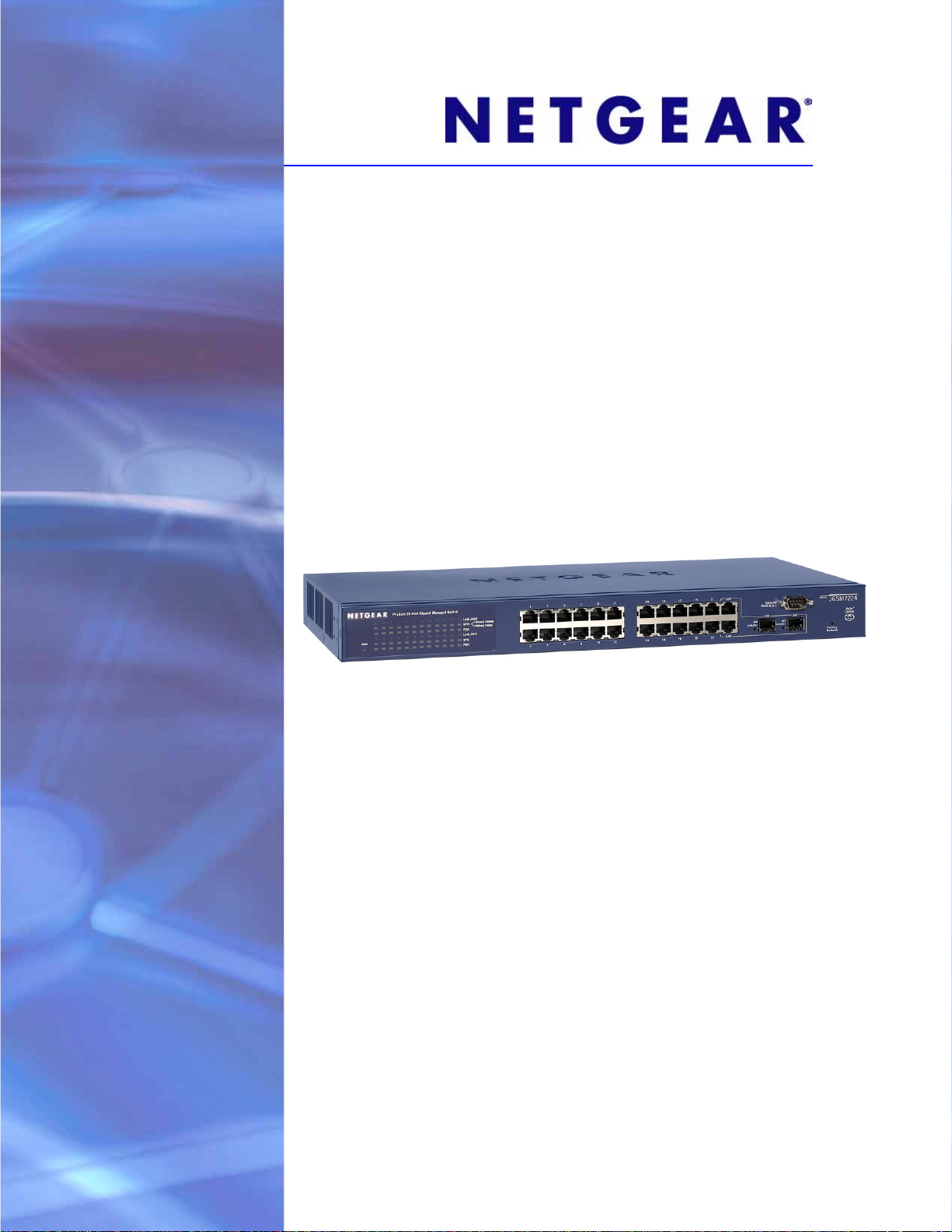
123456
Front Panel Ports and LEDs
The following figure shows the front panel ports and status LEDs of the switch.
Figure 1.
From left to right, the switch’s front panel shows the following LEDs and ports:
1. LEDs for th
2. 24 10/
e 24 Ethernet ports.
100/1000 Mbps LAN Ethernet ports with RJ-45 connectors. All Ethernet ports provide
switched N-way, automatic speed negotiating, auto MDI/MDIX technology.
3. One Gigabit
module bay (23F) in which an optional small form-factor pluggable (SFP) GBIC
transceiver module can be installed.
4. One Gigabit
module bay (24F) in which another optional SFP GBIC transceiver module can
be installed.
For bays 23F and 24F, the following modules are supported:
• AGM731F. 1000BASE-SX SFP GBIC for
Gigabit Ethernet short-reach fiber
connectivity.
• AGM732F. 1000BASE-LX SFP GBIC
for Gigabit Ethernet short-reach fiber
connectivity.
Note: If you install SFP modules in bays 23F and 24F, ports 23T and 24T
cannot be used, and their associated LEDs are off.
5. An RS-232 port for connecting to an optional console terminal. The port has a DB9 male
connector. The default baud rate is 9600 K. The configuration is 8 bits, no parity, and 1 stop
bit.
recessed Factory Defaults Reset button. Using a sharp object, press and hold this button
6. A
for about 10 seconds until the front panel LED flashes and the switch returns to factory
ault settings.
def
Note: If you reset the switch to factory default settings, all configuration
settings are lost, and the default IP address and subnet, user name,
and password are restored. (By default, the password is blank, that
is, do not enter anything.)
Introduction and Getting St arted
10
ProSafe 24-Port Gigabit L2 Managed Switch JGSM7224
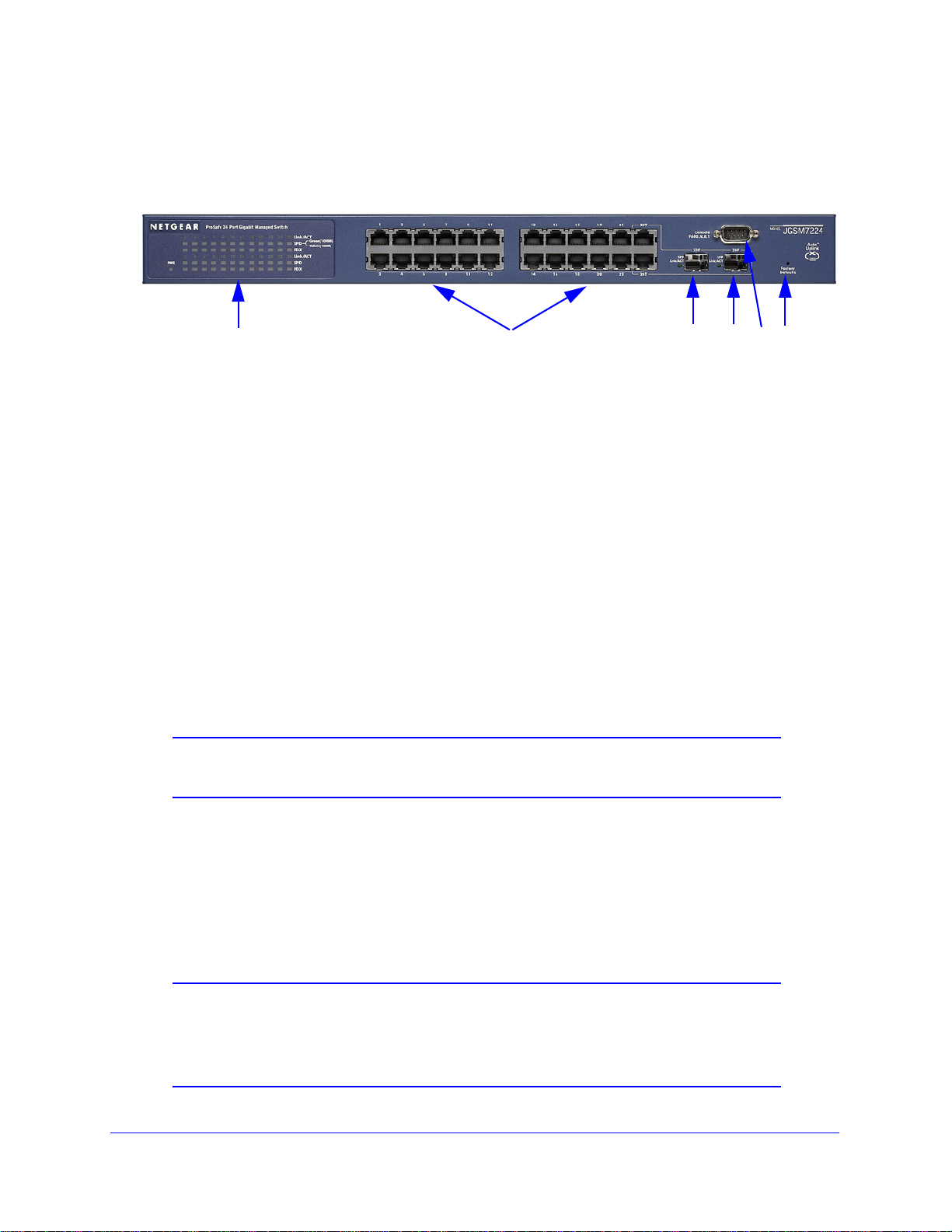
The function of each LED is described in the following table:
Table 1. LED and port functions
LED LED status Description
General LED
Power Off Power is disconnected.
Solid green Power is supplied to the switch and is operating normally.
Solid yellow The switch is starting up. When the startup process is
solid green.
10/100/1000 Mbps LAN Ethernet port LEDs for ports 1 through 22, 23T, and 24T
Link/ACT
(one per port)
SPD
(one per port)
FDX
(one per port)
LEDs for bays 23F and 24F
SFP Link/ACT
(one per module)
Off No link is established on the port.
Solid green A valid link is established on the port.
Flashing green Traffic transmission or reception occurs on the port.
Off • The SPD LED is off and the Link/ACT LED is on: A valid 10 Mbps link
s established on the port.
i
• The SPD LED is off and the Link/ACT LED is off: No 10/100/1000
ps link is established on the port.
Mb
Solid yellow A valid 100 Mbps link is established on the port.
Solid green A valid 1000 Mbps link is established on the port.
Off A half-duplex link is established on the port, or a full-duplex link is not
stablished on the port.
e
Solid green A full-duplex link is established on the port.
Off No SFP module link is established on the port.
Solid green A valid 1000 Mbps SFP module link is established on the port.
finished, the LED is
Flashing green Traffic transmission or reception occurs at 1000 Mbps on the module.
Rear Panel
The following figure shows the single rear panel component of the switch, the AC power
socket. Attach the power cord to this socket. (There is no separate power on/off switch.)
Figure 2.
Introduction and Getting St arted
11

ProSafe 24-Port Gigabit L2 Managed Switch JGSM7224
Bottom Panel with Product Label
The product label on the bottom panel of the switch’s enclosure displays the MAC address,
serial number, regulatory compliance, input power, and other information.
Figure 3.
Connect the Switch to the Network
To connect the switch physically to your network, connect the cables according to the
instructions in the installation guide. See the ProSafe® 24-Port Gigabit L2 Managed Switch
Installation Guide for complete steps. A PDF of the installation guide is on the NETGEAR
support website.
Switch Management Methods
The switch functions as a simple switch without the management software . However , you can
use the management software to configure more advanced features that can improve switch
efficiency and overall network performance.
You can use one of the following management functions to configure an
eb management interface (see Configure Access to the Web Management Interface on
• W
page 13)
• Command-line
Configure the Switch with a Static IP Address o
• Simple Network Ma
Protocol on
• Remot
e Network Monitoring (RMON; see Remote Network Monitoring on page 279)
interface (CLI; see the JGSM7224 CLI Reference Manual, and see also
n page 15)
nagement Protocol (SNMP; see Simple Network Management
page 55)
d monitor the switch:
Introduction and Getting St arted
12

ProSafe 24-Port Gigabit L2 Managed Switch JGSM7224
Note: To configure the switch by using SNMP or RMON, you first need to
configure these functions on the switch through accessing the web
management interface or CLI.
The first three of these standards-based management methods let you both configure and
monitor the components of the switch. The fourth method lets you monitor the component s of
the switch only . The method that you use to manage and monitor the switch depends on your
network size and requirements, and on your preference.
Configure Access to the Web Management Interface
The web management interface lets you monitor, configure, and control the switch remotely
using a standard web browser so you do not have to use SNMP software products. From
your web browser, you can monitor the performance of your switch and optimize its
configuration for your network. You can configure all switch features, such as VLANs, QoS,
and ACLs by using the web management interface.
Before you can access the web management interface from a computer, you need to
configure t
whether there is a DHCP server in the network, follow one of the procedures that are
described in the following sections:
• Configure Access When the Switch Functions in DHCP Client Mode without a DHCP
Server on
• Configure Access When the Switch Functions
on page 14
• Configure the Switch with a Static IP Address on p
he computer for access. Depending upon how your computer is set up and
page 13
in DHCP Client Mode with a DHCP Server
age 15
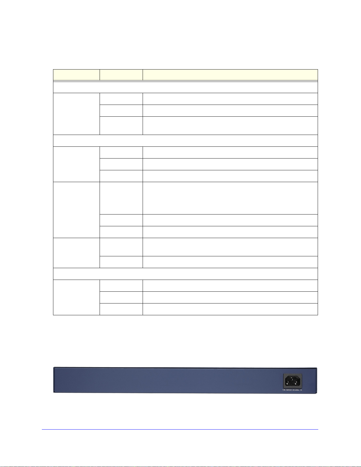
Configure Access When the Switch Functions in DHCP Client Mode without a DHCP Server
If there is no DHCP server in your network, the switch assumes a default IP address of
169.254.100.100 and subnet mask of 255.255.0.0. Use this IP address and subnet mask to
log in to the switch (see Log In to the Web Management Interface on
You can connect directly to the switch from a computer. The IP address of the computer
n
eeds to be in the same subnet as the default IP address on the switch. For most networks,
this means that you need to change the IP address of the computer to be on the same subnet
as the default IP address (169.254.100.100) of the switch. For example, configure the
computer with IP address 169.254.100.80 and subnet mask 255.255.0.0.
page 17).
To change the IP address on a computer that is run
system, open the Internet Protocol (TCP/IP) Properties screen that you can access from the
Local Area Connection Properties screen, as shown in the following figure. You need
Windows administrator privileges to change these settings.
Introduction and Getting St arted
13
ning a Microsoft Windows operating
ProSafe 24-Port Gigabit L2 Managed Switch JGSM7224
WARNING:
Figure 4.
When you change the IP address of your administrative system,
you lose your connection to the network. Write down your current
network address settings before you change them.
To modify the network settings on your management computer:
1. On
a computer that is running a Microsoft Windows operating system, open the Internet
Protocol (TCP/IP) Properties screen.
2. Set
the IP address of the administrative system to an address in the 169.254.100.0 network,
such as 169.254.100.80. The IP address needs to be different from that of the switch but
within the same subnet.
3. Click OK.
For information about how to log in to the switch, see Log In to the Web Management
Interface o
n page 17.
Configure Access When the Switch Functions in DHCP Client Mode with a DHCP Server
By default, the switch is configured as a DHCP client to obtain its IP address from a DHCP
server in the network. You need to access the switch from the console port.
Introduction and Getting St arted
14

ProSafe 24-Port Gigabit L2 Managed Switch JGSM7224
To determine the IP address of the switch if the IP address has been assigned by a
DHCP server on the network:
1. Make sure t
2. Conn
ect a console to the sw it c h. Using the null-modem cable sup plied with the s w i tc h,
hat the switch is connected to a DHCP server.
connect a VT100/ANSI terminal or workstation to console port of the switch (see Figure 1 on
page 10).
3. S
tart and configure a terminal emulation program (TEP):
a. S
tart a TEP using the appropriate method for your operating system:
• W
indows users can use HyperTerminal.
• W
indows Vista users should download a TEP from the Internet.
• Macintosh users can u
• UNIX users can u
b. Con
figure the TEP to use the following settings (they are written next to the console
se ZTerm.
se a terminal emulator such as TIP.
port connector on the front panel of the switch):
• Bau
• D
d rate: 9,600 bps
ata bits: 8
• Parity: none
• S
top bit: 1
• F
low control: none
4. Log in to the s
a. At t
he User: command prompt, type admin, and press Enter.
wit ch :
b. At the passwo
rd: command prompt, just press Enter again (the password is blank,
that is, do not enter anything).
The (JGS
ype the show management vlan command, and press Enter.
5. T
M7224)> prompt displays.
The IP address of the switch is now displayed onscreen.
Use this IP address to log in to the switch through its web management interface (see Lo g In
to the Web Management Interface o
n page 17).
Configure the Switch with a Static IP Address
If the network has no DHCP service, you need to assign a static IP address to the switch. If
you prefer, you can also assign a static IP address to the switch even if the network has
DHCP service.
To access the switch from the console port to assign a static IP address:
1. Con
nect a console to the switch. Using the null-modem cable supplied with the switch,
connect a VT100/ANSI terminal or workstation to console port of the switch (see
Figure 1 on p
age 10).
Introduction and Getting St arted
15

ProSafe 24-Port Gigabit L2 Managed Switch JGSM7224
2. Start and configure a terminal emulation program (TEP):
a. S
tart a TEP using the appropriate method for your operating system:
• Wind
• Wind
ows users can use HyperTerminal.
ows Vista users should download a TEP from the Internet.
• Macint
• UNIX u
b. Config
osh users can use ZTerm.
sers can use a terminal emulator such as TIP.
ure the TEP to use the following settings (they are written next to the console
port connector on the front panel of the switch):
te: 9,600 bps
a bits: 8
e
e
ser: command prompt, type admin, and press Enter.
3. Log
a. At the U
b. At t
• Baud ra
• Dat
• Parity: non
top bit: 1
• S
• Flow control: non
in to the switch:
he password: command prompt, just press Enter again (the password is blank,
that is, do not enter anything).
The (
JGSM7224)> prompt displays.
4. Use
the following CLI commands to set a static IP address and subnet mask. (For more
information, see the JGSM7224 CLI Reference Manual.)
The IP address (10.10.10.1) and subnet (255.255.255.0) that are used in the following
procedure
are only an example. End each command line by pressing Enter.
(JGSM7224) >
(JGSM7224) #
(JGSM7224) (config)#
(JGSM7224) (config-if)#
(JGSM7224) (config-if)#
(JGSM7224) (config-if)#
(JGSM7224) (config)#
(JGSM7224) # save
Building configuration ...
[OK]
(JGSM7224) #
enable
configure terminal
interface vlanmgmt
no ip address
ip address 10.10.10.1 255.255.255.0
exit
exit
Use this static IP address to log in to the switch through its web management interface (see
the following section).
Introduction and Getting St arted
16
ProSafe 24-Port Gigabit L2 Managed Switch JGSM7224
Log In to the Web Management Interface
To access the switch by using a web browser, the browser needs to meet the following
software requirements:
• HTML version 4.0
• HTTP version 1
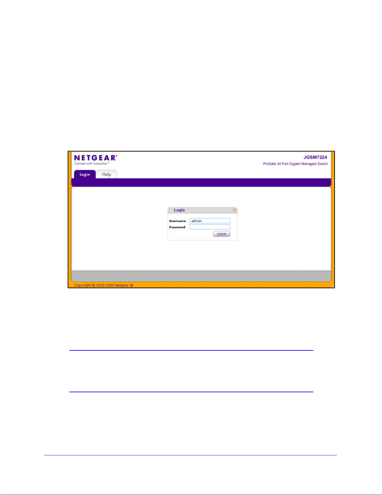
To log on to the web management interface:
1. Open
a web browser and enter the IP address of the switch in the web browser address
field. (The default IP address is 169.254.100.100.) The Login screen displays:
, or later
.0, or later
Figure 5.
2. Type admin as the default user name and leave the password blank, that is, there is no
default password, so do n ot e nt e r a n y th i n g. (User na mes are case-sensitive.)
3. Click Login. Af
ter authentication, the System Information screen displays (see Figure 6 on
page 18).
Note: For information about how to change the login method, see Login
Authentication on
the session time-out period, see HTTP on
page 176. For information about how to change
page 178 and HTTPS
Configuration on page 179.
Introduction and Getting St arted
17
ProSafe 24-Port Gigabit L2 Managed Switch JGSM7224
1st level, main navigation tabs
2nd level, configuration menus
3rd level, links
Context-sensitive help
Command buttons
Web Management Interface Layout
The web management interface consists of four levels:
• 1st le
vel—main navigation tabs. The main navigation tabs along the top of the web
management interface give you quick access to the various switch functions. The tabs
are always available and remain constant, regardless of your configuration activity.
• 2nd le
vel—configuration menus. When you select a main navigation tab, the
configuration menus for that tab display as links directly under the tabs. The configuration
menus in the blue bar change according to the main navigation tab that is selected.
• 3rd leve
l—links. The links for each configuration menu are available on the left side of
the screen. The links provide direct access to a screen.
• 4th level—su
bmenus with links. Some links in a configuration menu expand to reve al a
submenu with multiple links as the following figure shows. When you click a link that is a
submenu, a down arrow symbol is displayed to the left of the link.
Levels 1 through 3 are shown in the following figure. Level 4 is shown in Figure 7 on
page 19.
Figure 6.
Introduction and Getting St arted
18
ProSafe 24-Port Gigabit L2 Managed Switch JGSM7224
4th level, submenu and links
Figure 7.
Command Buttons
The following table describes the functions of the command buttons that ar e used throughout
the screens of the web management interface:
Table 2. Web management interface command buttons
Button Function
Add Adds the new item to the table.
Apply Sends the updated configuration to the swi
immediately. Changes are not retained when you reboot the switch unless you save the
changes to the startup configuration file.
Note: Make sure that you save the configuration
changes. Go to the Save Configuration screen (Maintenance > Save Configuration) to
save the configuration changes to the startup configuration file. For more information, see
Save Configuration on
Cancel Cancels the configuration onscreen and resets the da
values of the switch.
Clear Resets one or more counters.
page 296.
tch. Configuration changes take effect
after you have applied the configuration
ta onscreen to the most recent
Delete Removes the selected item or items from the table.
Refresh Updates the information onscreen to the most recent values of the switch.
Logout Ends the session.
Introduction and Getting St arted
19

ProSafe 24-Port Gigabit L2 Managed Switch JGSM7224
Context-Sensitive Help
Each screen contains access to HTML-based help that explains the fields and configuration
options for the screen. Click the red question mark to display the help screen.
Interface Naming Conventions
The switch supports physical and logical interfaces. The logical interfaces are link
aggregation groups (LAGs), also referred to as port channels. Interfaces are identified by
their type and the interface number. The physical ports are Gigabit interfaces and are
numbered on the front panel. You configure the logical interfaces by using the web
management interface or CLI. The following table describes the naming conventions for
these interfaces:
Table 3. Interface naming conventions
Interface Description Examples
Physical The physical ports are Gigabit Ethernet interfaces and are
numbered sequentially starting from 0/1 through 0/24.
Link aggregation
up (LAG)
gro
LAG interfaces are logical interfaces that are used only for bridging
functions. There are eight preconfigured link aggregation groups to
which you can add individual interfaces.
0/1, 0/2, 0/3, and so on
through 0/24
po1, po2, po3. po4,
po5, po6, po7, and po8
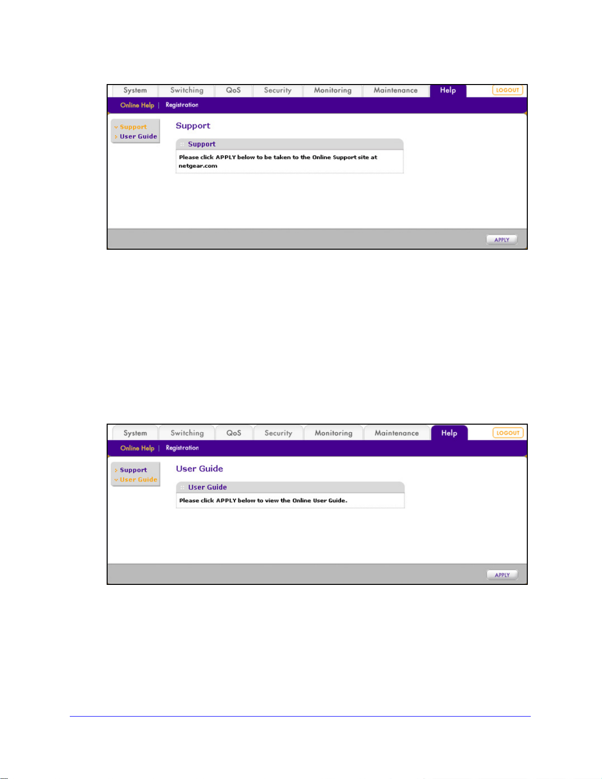
Online Help
The Help main navigation tab of the web management interface provides access to the menus
that are described in the following sections:
• Support
• User Guide
Support
The Support screen provides access to the NETGEAR support website at
support.netgear.com.
To access the support website from the web management interface:
1. Select Help >
Support. The Support screen displays:
Introduction and Getting St arted
20
ProSafe 24-Port Gigabit L2 Managed Switch JGSM7224
Figure 8.
2. Click Apply to connect to the NETGEAR support website for the switch.
User Guide
The ProSafe 24-Port Gigabit L2 Managed Switch JGSM7224 Reference Manual (the guide
that you are now reading) is available at the NETGEAR download center at
downloadcenter.netgear.com.
To access the reference manual online from the web management interface:
1. Select Help
Figure 9.
> > Online Help > User Guide. The User Guide screen displays:
2. Click Apply to access the NETGEAR download center.
3. Ente
4. Locate the ProSafe 24
r the model number (JGSM7224).
-Port Gigabit L2 Managed Switch JGSM7224 Reference Manual
on the product support web page.
Introduction and Getting St arted
21
ProSafe 24-Port Gigabit L2 Managed Switch JGSM7224
Registration
To qualify for product updates and product warranty, NETGEAR encourages you to register
your product. The first time that you connect to the switch while it is connected to the Internet,
you have the option to register your product. At any time, you can register your product from
the web management interface, or you can visit the NETGEAR website for registration at
https://my.netgear.com/registration/login.aspx.
To register the switch with NETGEAR:
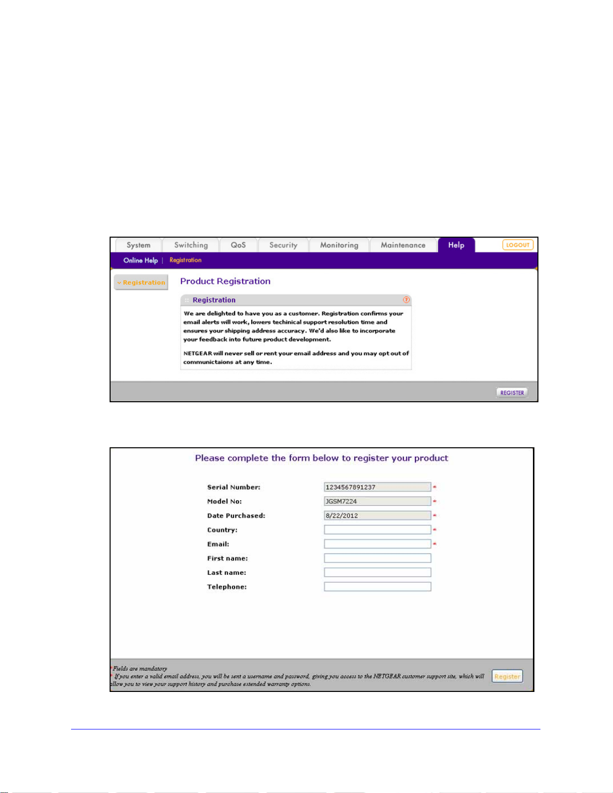
1. Select Help >
Figure 10.
Register. The Registration screen displays:
2. Click Register. A new screen displays in your browser:
Figure 11.
Introduction and Getting St arted
22
ProSafe 24-Port Gigabit L2 Managed Switch JGSM7224
3. Enter the information in the blank fields. The serial number, model number, and date of
purchase are entered automatically.
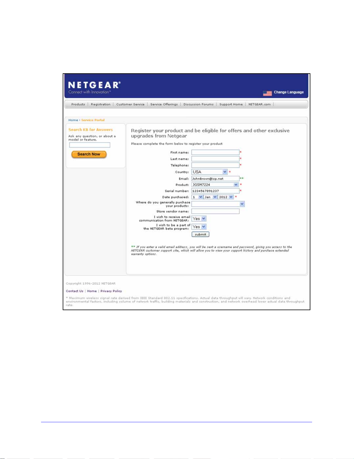
4. Click Regi
ster. The registration web page displays:
Figure 12.
5. Complete the registration form.
6. Click submit.
Introduction and Getting St arted
23

2. Configuring the System
IMPORTANT:
The System main navigation tab lets you define the relationship of the switch to its environment
through the features that are described in the following sections:
• Management Settings
• Services: DHCP Server and DHCP Layer 2 Relay
• Simple Network Management Protocol
• Link Layer Discovery Protocol
Make sure that you save the configuration after you have applied
the configuration changes. Go to the Save Configuration screen
(Maintenance > Save Configuration) to save the configuration
changes to the startup configuration file.
2
Management Settings
This section describes how to display the switch status and specify some basic switch
information, such as the management interface IP address, system clock settings, and DNS
information. The Management configuration menu has the links that are described in the
following sections:
• System Information
• System CPU Status
• Green Ethernet Configuration
• Denial of Service
• Network Interface
• Time
• DNS
24
ProSafe 24-Port Gigabit L2 Managed Switch JGSM7224
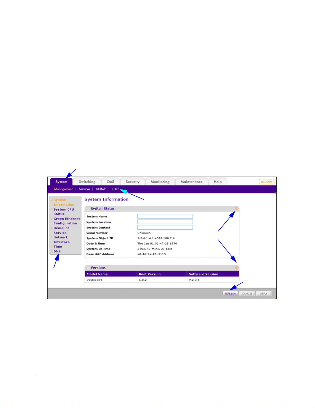
System Information
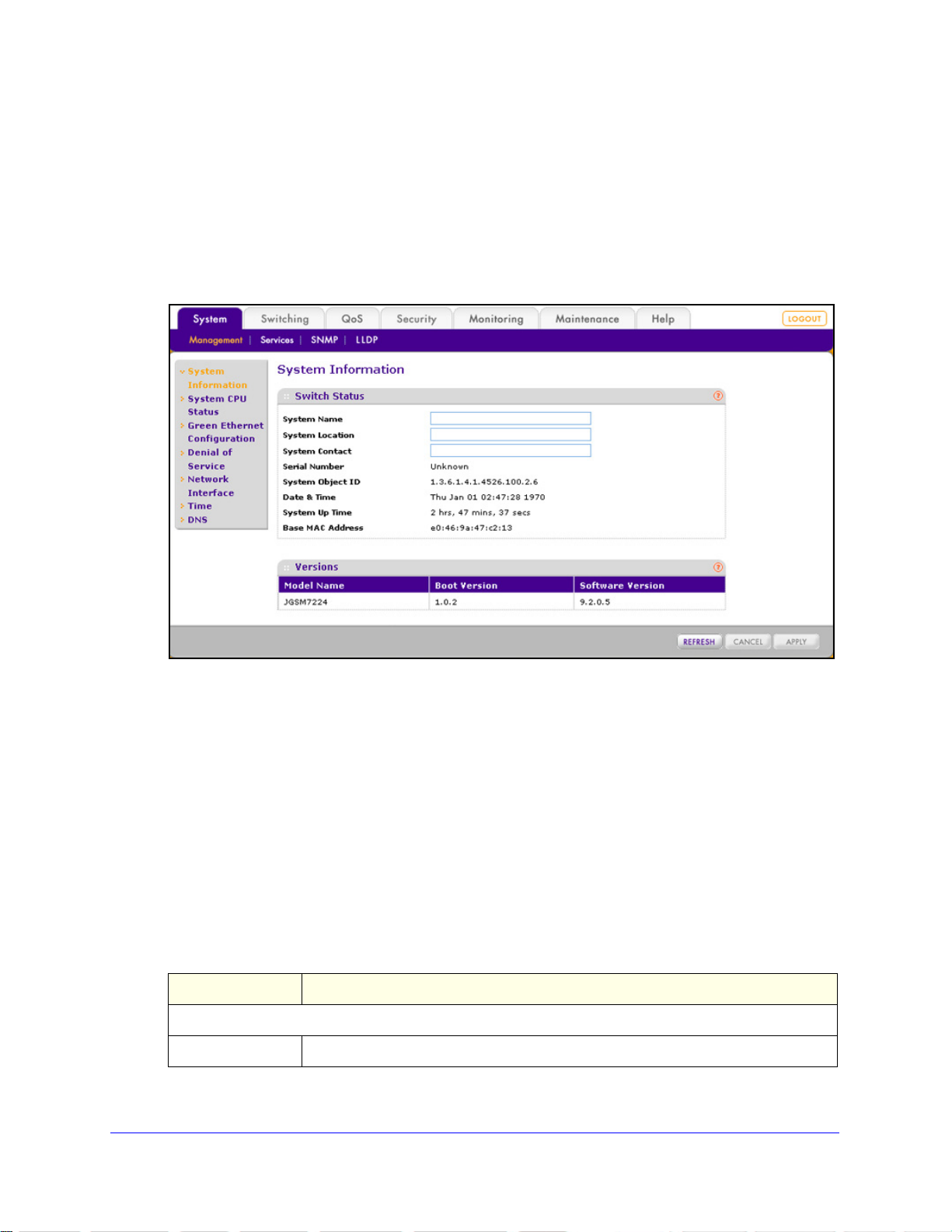
After a successful login, the System Information screen displays. Use this screen to configure
and view general device information.
To specify the system name, location, and contact:
1. Select System >
displays:
Figure 13.
Management > System Information. The System Information screen
2. Configure the following optional settings:
• System Name. S
pecify a name to identify the switch. Enter up to 31 alphanumeric
characters. There is no default system name.
• Sys
tem Location. Specify the location of this switch. Enter up to 31 alphanumeric
characters. There is no default system location.
• Sys
tem Contact. Enter the contact person for the switch. Enter up to 31
alphanumeric characters. There is no default system contact.
3. Click App
ly to apply the changes.
The following table describes the nonconfigurable fields
Versions sections on the System Information screen:
Table 4. System Information screen settings
Item Description
Switch Status
Serial Number The serial number of the switch.
Configuring the System
25
in the Switch Status and
ProSafe 24-Port Gigabit L2 Managed Switch JGSM7224
Table 4. System Information screen settings (continued)
Item Description
System Object ID The base object ID for the enterprise Management Information Base (MIB) of the
switch.
Date & Time The current date and time.
System Up Time The number of days, hours,
Base MAC Address The MAC address of the switch.
Versions
Model Name The model name of the switch.
Boot Version The boot code version of the switch.
Software Version The software version of the switch.
and minutes since the switch was last started.
System CPU Status
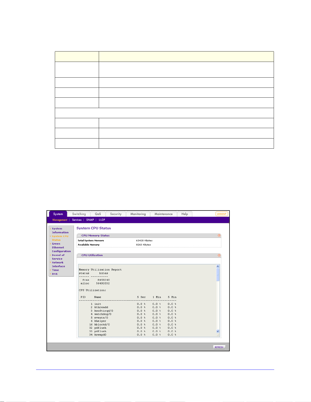
To display the CPU status of the switch, including total system memory, available
system memory, and CPU utilization:
Select S
displays:
ystem > Management > System CPU Status. The System CPU Status screen
Figure 14.
Configuring the System
26
ProSafe 24-Port Gigabit L2 Managed Switch JGSM7224
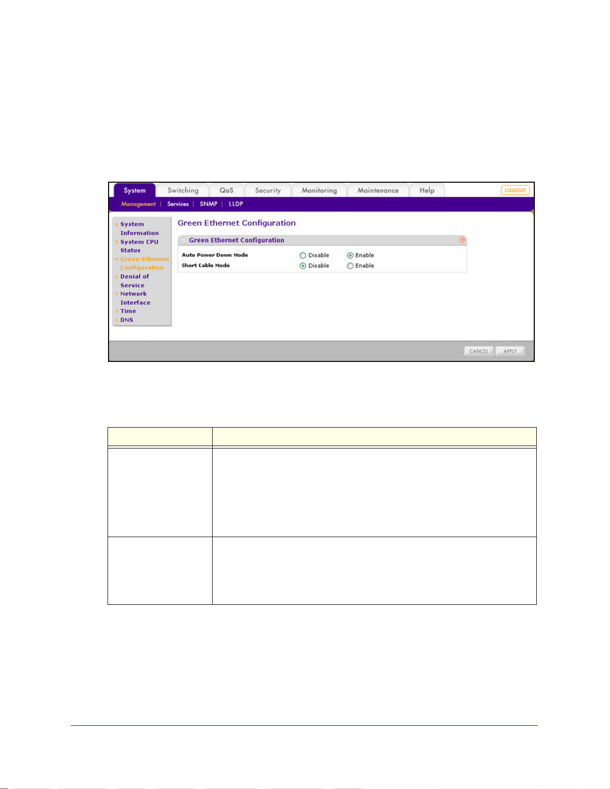
Green Ethernet Configuration
Green Ethernet features allow for power consumption savings.
To configure the Green Ethernet features:
1. Select System
> Management > Green Ethernet Configuration. The Green Ethernet
Configuration screen displays:
Figure 15.
2. Configure the settings as explained in the following table:
Table 5. Green Ethernet Configuration screen settings
Setting Description
Auto Power Down Mode Select one of the following radio buttons:
• Disa
• Enable.
Short Cable Mode Select one of the following radio buttons:
• Disa
• Enable. I
3. Click App
ly to apply the changes.
ble. Autonegotiation continues, and there is no power consumption
saving while an interface is down.
When a link to a switch interface is down, the inte rface
automatically goes into standby mode and checks the status of the link at
regular intervals. Power consumption is saved, and no autonegotiation is
performed while the link is down. This is the default setting.
ble. Full transmit power is provided to all switch interfaces, regardless
of cable lengths. This is the default setting.
f a cable that is attached to a switch interface is less than 10
meters in length, the interface is automatically placed in low-power mode.
Configuring the System
27
ProSafe 24-Port Gigabit L2 Managed Switch JGSM7224
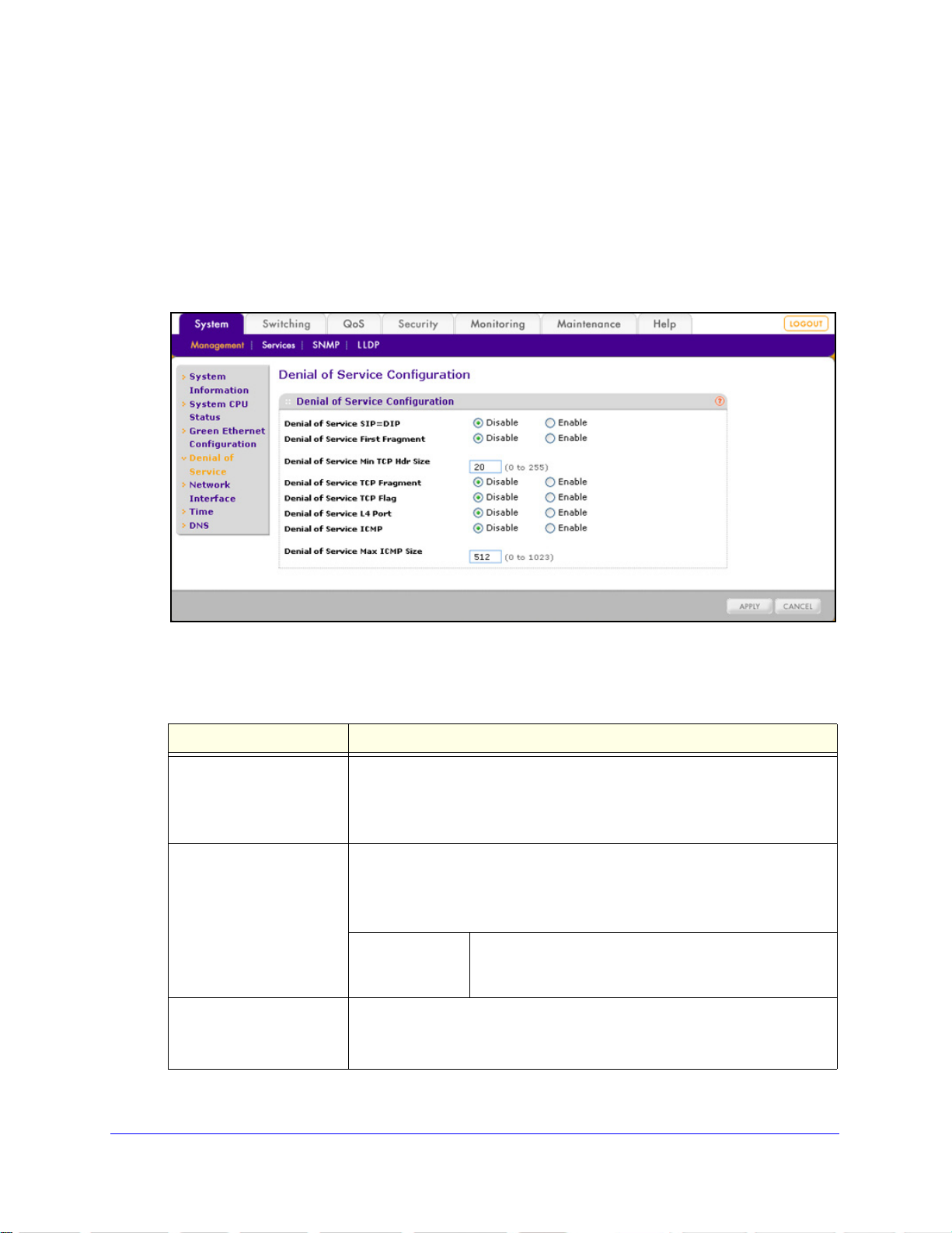
Denial of Service
Y ou can configure the switch to monitor and blo ck six types of denial of service (DoS) att acks,
which are explained in the following figure and table.
To manually configure DoS settings:
1. Select System >
Management > Denial of Service. The Denial of Service Configuration
screen displays:
Figure 16.
2. Configure the settings as explained in the following table:
Table 6. Denial of Service Configuration screen settings
Setting Description
Denial of Service SIP=DIP Select one of the following radio buttons:
le. This is the default setting.
Packets that have a source IP (SIP) address equal to the
destination IP (DIP) address are dropped.
le. This is the default setting.
Packets with a TCP header that is smaller than the configured
minimum TCP header size are dropped.
Specify the minimum TCP header size. Enter a value in
Hdr Size
le. This is the default setting.
Configuring the System
the range from 0 to 255 bytes. The default setting is
20 bytes.
s that have an IP fragment offset equal to 1 are dropped.
28
Denial of Service First
ragment
F
Denial of Service TCP
ragment
F
• Disab
• Enable.
Select one of the following radio buttons:
• Disab
• Enable.
Denial of Service
Min TCP
Select one of the following radio buttons:
• Disab
• Enable. Packet

ProSafe 24-Port Gigabit L2 Managed Switch JGSM7224
Table 6. Denial of Service Configuration screen settings
Setting Description
Denial of Service TCP Flag Select one of the following radio buttons:
• Disa
• Enable. All of the following packets are dropped:
Denial of Service L4 Port Select one of the following radio buttons:
• Disa
• Enable. Packe
ble. This is the default setting.
- Packets that have a TCP flag SYN set and a TCP source port with a
umber lower than 1024
n
- Packets that have TCP control flags set to 0 and the TCP sequence
number set
- Packets that have TCP flags FIN, URG, and PSH set and TCP
sequence number
- Packets that have both the TCP flags SYN and FIN set
ble. This is the default setting.
destination port are dropped, and packets that have a UDP source port
that is equal to the UDP destination port are dropped.
to 0
set to 0
ts that have a TCP source port that is equal to the TCP
Denial of Service ICMP Select one of the following radio buttons:
• Disa
• Enable. ICMP packets that have the type set to ECHO_REQ (ping) and a
Denial of Service
Max ICM
ble. This is the default setting.
size greater than the configured ICMP packet size are dropped.
Specify the maximum ICMP packet size. Enter a value in
P Size
the range from 0 to 1023 bytes. The default setting is
512 bytes.
3. Click Apply to apply the changes.
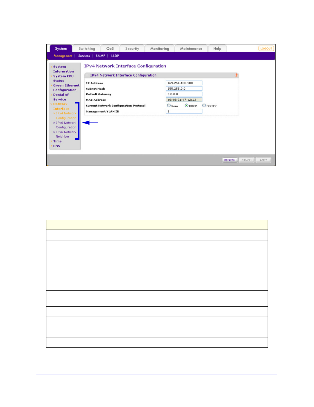
Network Interface
The network interface is the logical interface that is used for inband connectivity with the
switch through any of its front panel port s. The configuration of the net work interface does not
affect the configuration of the front panel ports through which traffic is switched or routed.
The Management configuration menu h
are described in the following sections:
• IPv4 Network Configuration
• IPv6 Network configuration
• IPv6 Network Neighbor
as a Network Interface submenu with the links that
IPv4 Network Configuration
To access the switch in a network, you need to configure a static IP address, subnet mask,
and default gateway or enable DHCP or BOOTP so the switch can receive a dynamic IP
address, subnet mask, and default gateway.
Configuring the System
29
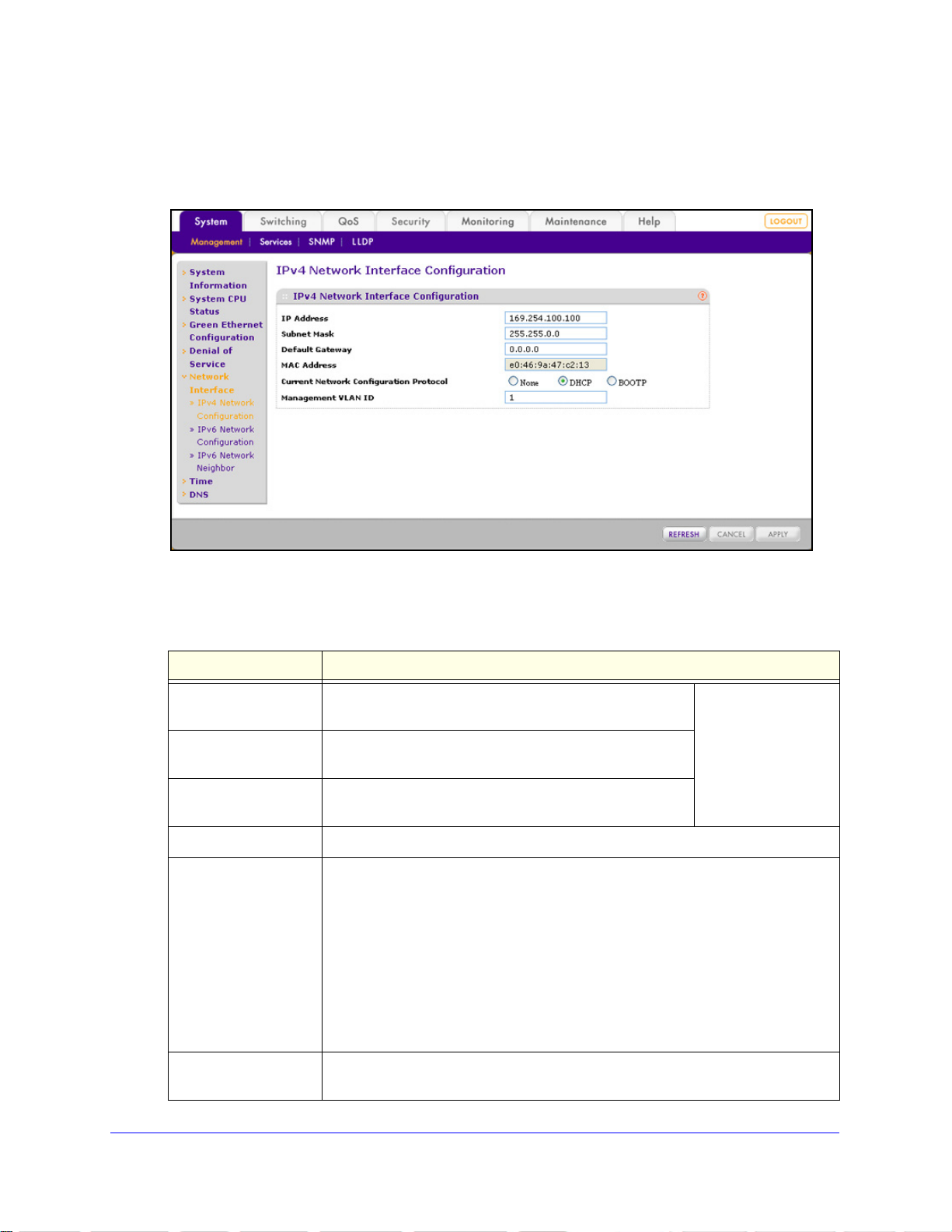
ProSafe 24-Port Gigabit L2 Managed Switch JGSM7224
To configure the IPv4 network settings:
1. Select Sy
stem > Management > Network Interface > IPv4 Network Confi guration. The
IPv4 Network Interface Configuration screen displays:
Figure 17.
2. Configure the settings as explained in the following table:
Table 7. IPv4 Network Interface Configuration screen settings
Setting Description
IP Address Enter the IP address of the network interface. The default
address is 169.254.100.100.
Subnet Mask Enter the IP subnet mask for the interface. The default
sk is 255.255.0.0.
ma
Default Gateway Enter the default gateway for the IP interface. The default
ddress is 0.0.0.0.
a
MAC Address This nonconfigurable field shows the fixed
Current Network
nfiguration Protocol
Co
Management VLAN ID Enter the management VLAN ID that is used to manage the switch. The VLAN ID
Select one of the following radio buttons to specify how the switch receives its IP
information:
ne. The switch does not receive its IP information from a server; you need
• No
to enter static IP address information.
HCP. The switch functio ns as a DHCP client and automatically receives IP
• D
information through a Dynamic Host Configuration Protocol (DHCP) server on
the network (see DHCP Server Configuration on p
setting.
OTP. The switch func tions as a DHCP client and automatically receives IP
• BO
information through a Bootstrap Protocol (BOOTP) server on the network.
n be in the range from 1 to 4094. The default VLAN ID is 1.
ca
MAC address of the switch.
If you select the
DHCP or BOOTP
radio button, these
fields are masked out.
age 43). This is the default
Configuring the System
30
 Loading...