

Page 1
Managed Switch JGSM7224
Hardware Installation Guide
350 East Plumeria Drive
San Jose, CA 95134
USA
September 2012
202-10881-03
1.0
Page 2

ProSafe 24-Port Managed Switch JGSM7224
No part of this publication may be reproduced, transmitted, transcribed, stored in a retrieval system, or translated into
any language in any form or by any means without the written permission of NETGEAR, Inc.
NETGEAR, the NETGEAR logo, and Connect with Innovation are trademarks and/or registered trademarks of
NETGEAR, Inc. and/or its subsidiaries in the United States and/or other countries. Information is subject to change
without notice. Other brand and product names are registered trademarks or trademarks of their respective holders.
© 2012 All rights reserved.
Technical Support
Thank you for choosing NETGEAR. To register your product, get the latest product updates, get support online, or for
more information about the topics covered in this manual, visit the Support website at
http://support.netgear.com
Phone (US & Canada only): 1-888-NETGEAR
Phone (Other Countries): Check the list of phone numbers at
http://support.netgear.com/general/contact/default.aspx
Statement of Conditions
To improve internal design, operational function, and/or reliability, NETGEAR reserves the right to make changes to the
products described in this document without notice. NETGEAR does not assume any liability that may occur due to the
use, or application of, the product(s) or circuit layout(s) described herein.
Revision History
Publication Part Number Version Publish Date Comments
202-10881-03 1.0 September 2012 First publication
6
Page 3

Contents
Chapter 1 Introduction
Chapter 2 Hardware Installation
JGSM7224 Front Panel and LEDs . . . . . . . . . . . . . . . . . . . . . . . . . . . . . . . . 4
JGSM7224 Rear Panel. . . . . . . . . . . . . . . . . . . . . . . . . . . . . . . . . . . . . . . . . 5
Interpreting the LEDs . . . . . . . . . . . . . . . . . . . . . . . . . . . . . . . . . . . . . . . . . . 5
Safety Instructions . . . . . . . . . . . . . . . . . . . . . . . . . . . . . . . . . . . . . . . . . . . .5
Package Contents . . . . . . . . . . . . . . . . . . . . . . . . . . . . . . . . . . . . . . . . . . . . 8
Protecting Against Electrostatic Discharge. . . . . . . . . . . . . . . . . . . . . . . . . . 8
Unpacking the Hardware . . . . . . . . . . . . . . . . . . . . . . . . . . . . . . . . . . . . . . . 9
Installation . . . . . . . . . . . . . . . . . . . . . . . . . . . . . . . . . . . . . . . . . . . . . . . . . .9
Selecting a Location . . . . . . . . . . . . . . . . . . . . . . . . . . . . . . . . . . . . . . . . 10
Installing the Switch . . . . . . . . . . . . . . . . . . . . . . . . . . . . . . . . . . . . . . . . 10
Checking the Installation . . . . . . . . . . . . . . . . . . . . . . . . . . . . . . . . . . . .11
Connecting to Power and Check the LEDs . . . . . . . . . . . . . . . . . . . . . . 12
SFP Modules . . . . . . . . . . . . . . . . . . . . . . . . . . . . . . . . . . . . . . . . . . . . . . . 12
Connecting Equipment to the Switch . . . . . . . . . . . . . . . . . . . . . . . . . . . . . 13
RJ-45 Ports. . . . . . . . . . . . . . . . . . . . . . . . . . . . . . . . . . . . . . . . . . . . . . . 13
Connecting a Console to the Switch. . . . . . . . . . . . . . . . . . . . . . . . . . . . . . 13
Chapter 3 Troubleshooting
Troubleshooting Chart . . . . . . . . . . . . . . . . . . . . . . . . . . . . . . . . . . . . . . . . 15
Additional Troubleshooting Suggestions . . . . . . . . . . . . . . . . . . . . . . . . . . 16
Appendix A Hardware Specifications
Appendix B Notification of Compliance
Index
3
Page 4
1.
Introduction
This guide describes hardware installation and basic troubleshooting for the ProSafe™
24-Port Managed Switch JGSM7224. The NETGEAR managed switch is a state-of-the-art,
high-performance, IEEE-compliant network solution. It includes powerful management
features that you can use to eliminate bottlenecks, boost performance, and increase
productivity.
These switches can be free standing, or rack mounted in a wiring closet or an equipment
room. For information about features for these products, see the NETGEAR website at
http://www.netgear.com.
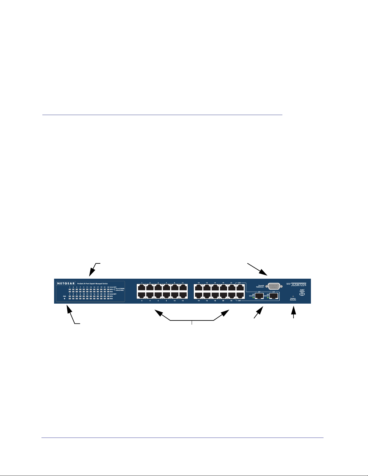
JGSM7224 Front Panel and LEDs
The following figure shows the front panel of the JGSM7224. The front panel contains LEDs,
a RST (reset) button, a USB port, RJ-45 jacks, and copper/fiber combo ports.
Port LEDs
Console Port
1
Power LED
RJ-45 Ports
Figure 1.
For information about the LEDs on the front panel of the switch, see Interpreting the LEDs on
page 5.
4
Copper/fiber
combo ports
Reset
button
Page 5
ProSafe™ 24-Port Managed Switch JGSM7224
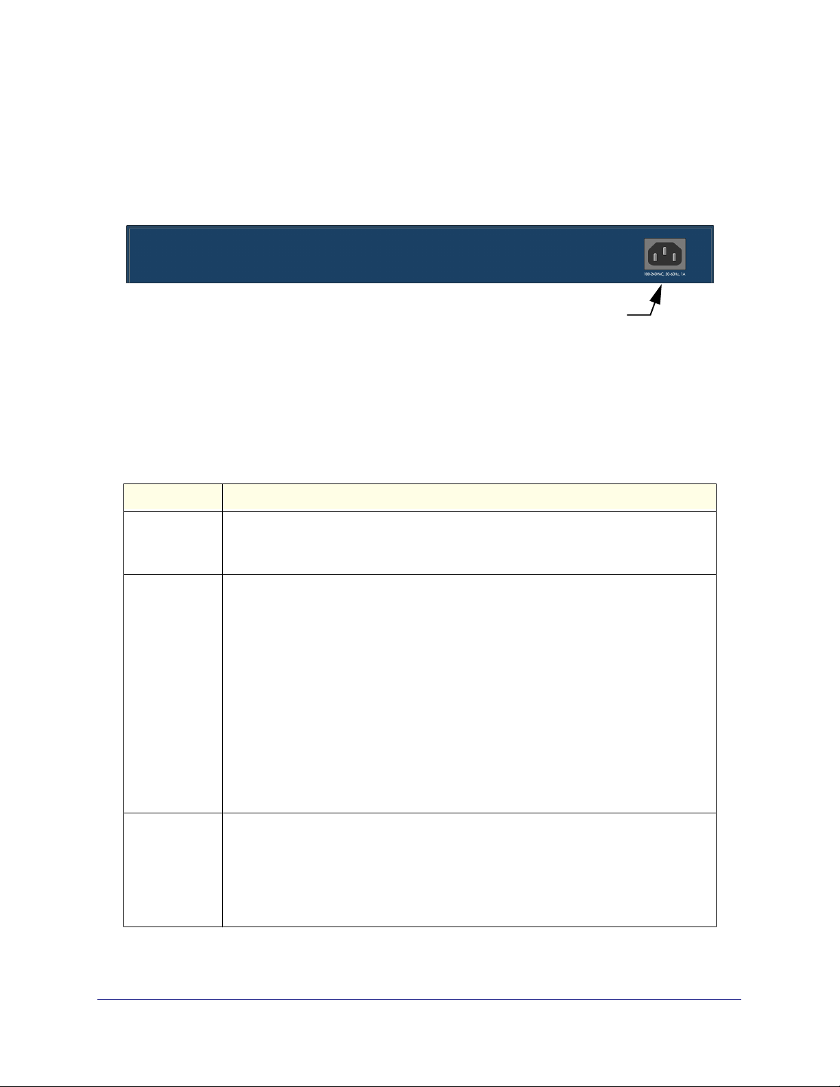
JGSM7224 Rear Panel
The rear panel has a console port, a redundant power supply connector, and a standard AC
power receptacle for the supplied power cord.
Power receptacle
Figure 2.
Interpreting the LEDs
The following table describes the LEDs on the front panel of the switch.
Table 1. LED Descriptions
LED Description
PWR (power) • Solid green. Power is supplied and the switch is working.
• Solid yellow. System is booting up.
• Off. Power is disconnected.
10/100/1000M
Ports (3 LEDs
per port)
SFP Ports
(1 LED per port)
Link/ACT
• Off. No link is established on the port.
• Solid green. A valid link is established on the port.
• Blinking green. The port is sending or receiving packets.
SPD
• Off. No link is established on the port or current valid link is 10 Mbps..
• Solid yellow. Current valid link is 100 Mbps.
• Solid green. Current valid link is 1000 Mbps.
FDX
• Off. No full-duplex link is established or half-duplex link is established on the port.
• Solid green. A full-duplex link is established on the port.
Note: If port 23–24 for the JGSM7224 media is changed to SFP, the RJ-45 LEDs
change to Off status.
SPD/Link/ACT LED
• Off. No SFP module link is established on the port.
• Solid green. A valid 1000 Mbps SFP module link is established on the port.
• Blinking green. The port is sending or receiving packets at 1000 Mbps.
Note: if port 23-24 for the switch is changed to fiber, the copper LEDs change to off
status.
Introduction
5
Page 6

ProSafe™ 24-Port Managed Switch JGSM7224
Safety Instructions
Use the following safety guidelines to ensure your own personal safety and to help protect
your system from potential damage.
To reduce the risk of bodily injury, electrical shock, fire, and damage to the equipment,
observe the following precautions:
• Observe and follow service markings.
- Do not service any product except as explained in your system documentation.
- Opening or removing covers that are marked with the triangular symbol with a
lightning bolt can expose you to electrical shock. Only a trained service technician
should service components inside these compartments.
• If any of the following conditions occur, unplug the product from the electrical outlet and
replace the part, or contact your trained service provider:
- The power cable, extension cable, or plug is damaged.
- An object has fallen into the product.
- The product has been exposed to water.
- The product has been dropped or damaged.
- The product does not operate correctly when you follow the operating instructions.
• Keep your system away from radiators and heat sources. Also, do not block cooling
vents.
• Do not spill food or liquids on your system components, and never operate the product in
a wet environment. If the system gets wet, contact technical support or your trained
service provider.
• Do not push any objects into the openings of your system. Doing so can cause fire or
electric shock by shorting out interior components.
• Use the product only with approved equipment.
• Allow the product to cool before removing covers or touching internal components.
• Operate the product only from the type of external power source indicated on the
electrical ratings label. If you are not sure of the type of power source required, consult
your service provider or local power company.
• To help avoid damaging your system, be sure that the voltage selection switch (if
provided) on the power supply is set to match the power available at your location:
- 115 volts (V), 60 hertz (Hz) in most of North and South America and some Far
Eastern countries such as South Korea and Taiwan
- 100 V, 50 Hz in eastern Japan and 100 V, 60 Hz in western Japan
- 230 V, 50 Hz in most of Europe, the Middle East, and the Far East
• Also, be sure that attached devices are electrically rated to operate with the power
available in your location.
• Use only approved power cables. If you have not been provided with a power cable for
your system or for any AC-powered option intended for your system, purchase a power
Introduction
6
Page 7

ProSafe™ 24-Port Managed Switch JGSM7224
cable that is approved for use in your country. The power cable must be rated for the
product and for the voltage and current marked on the product’s electrical ratings label.
The voltage and current rating of the cable should be greater than the ratings marked on
the product.
• To help prevent electric shock, plug the system and peripheral power cables into properly
grounded electrical outlets.
• The peripheral power cables are equipped with three-prong plugs to help ensure proper
grounding. Do not use adapter plugs or remove the grounding prong from a cable. If you
must use an extension cable, use a three-wire cable with properly grounded plugs.
• Observe extension cable and power strip ratings. Make sure that the total ampere rating
of all products plugged into the extension cable or power strip does not exceed 80
percent of the ampere ratings limit for the extension cable or power strip.
• To help protect your system from sudden, transient increases and decreases in electrical
power, use a surge suppressor, line conditioner, or uninterruptible power supply (UPS).
• Position system cables and power cables carefully; route cables so that they cannot be
stepped on or tripped over. Be sure that nothing rests on any cables.
• Do not modify power cables or plugs. Consult a licensed electrician or your power
company for site modifications.
• Always follow your local and national wiring rules.
• Move products with care; ensure that all casters and stabilizers are firmly connected to
the system. Avoid sudden stops and uneven surfaces.
Introduction
7
Page 8

2.
Hardware Installation
This chapter explains how to install the hardware for the ProSafe™ 24-Port Managed Switch
JGSM7224.
Package Contents
The switch is packed and shipped separately. The package contains the following items:
• Managed Switch with preinstalled software
• Power adapter cord
• Rubber footpads for tabletop installation
• Rubber caps for the SFP sockets
• Rack-mounting kit
• Null-modem serial console cable (RS-232) with 9-pin connectors
• Resource CD: The CD contains documentation including the Installation Guide, and link
to the ProSafe JGSM7224 Managed Switch CLI Reference Manual and the ProSafe
JGSM7224 Managed Switch Reference Manual.
2
• Installation Guide
Protecting Against Electrostatic Discharge
WARNING!
Static electricity can harm delicate components inside your
system. To prevent static damage, discharge static electricity
from your body before you touch any of the electronic
components, such as the microprocessor. You can do so by
periodically touching an unpainted metal surface on the switch.
You can also take the following steps to prevent damage from electrostatic discharge (ESD):
8
Page 9

ProSafe™ 24-Port Managed Switch JGSM7224
1. When unpacking a static-sensitive component from its shipping carton, leave it in the
antistatic package until you are ready to install it. Just before unwrapping the antistatic
package, discharge static electricity from your body.
2. Before moving a sensitive component, place it in an antistatic container or package.
3. Handle all sensitive components in a static-safe area. If possible, use antistatic floor pads,
workbench pads, and an antistatic grounding strap.
Unpacking the Hardware
Check the contents of the boxes to make sure that all items are present before beginning the
installation.
1. Place the container on a clean flat surface, and cut all straps securing the container.
2. Unpack the hardware from the boxes.
Carefully remove the hardware, and place it on a secure and clean surface. See
Selecting a Location on page 10.
3. Remove all packing material.
4. Make sure that all items are present. See Package Contents on page 8.
Note: If any item is found missing or damaged, contact your local
NETGEAR reseller for replacement.
5. Inspect the products and accessories for damage. Report any damage immediately.
Installation
Install the equipment in the following sequence, as presented in this chapter:
1. Select a location. See the following section, Selecting a Location .”
2. Install the switch. See Installing the Switch on page 10.
3. Check the installation. See Checking the Installation on page 11.
4. Apply power and check the LEDs. See Connecting to Power and Check the LEDs on
page 12.
Hardware Installation
9
Page 10

ProSafe™ 24-Port Managed Switch JGSM7224
Selecting a Location
The switch can be mounted in a standard 19-inch (48.26-centimeter) rack, wall mounted, or
left freestanding (placed on a tabletop). The site where you install the switch can greatly
affect its performance. Before installing the switch or switches, make sure that the chosen
installation location meets the following site requirements.
Table 1. Site Requirements for Switch Location
Requirements
Mounting • Desktop Installations. Provide a flat table or shelf surface.
• Rack-mount Installations. Use a 19-inch (48.3-centimeter) EIA standard
equipment rack that is grounded and physically secure, and the rack-mounting kit
supplied with your switch.
Access Put the switch in a position that lets you access the front panel RJ-45 ports, view the
front panel LEDs, and access the rear panel power connector.
Power source Provide a power source within 6 feet (1.8 meters) of the installation location. Power
specifications for the switch are shown in Appendix A.” Be sure that the AC outlet is
not controlled by a wall switch, which can accidentally turn off power to the outlet and
the switch.
Environment Install the switch in a site free from strong electromagnetic field generators (such as
motors), vibration, dust, and direct exposure to sunlight.
Temperature The ambient switch operating temperature range is 0º to 55ºC (32º and 131ºF). Keep
the switch away from heat sources such as direct sunlight, warm-air exhausts, hot-air
vents, and heaters.
Operating humidity Install the switch in a dry area with a maximum relative humidity of 90%,
noncondensing.
Ventilation Do not restrict airflow by covering or obstructing air inlets on the sides of the switch.
Keep at least 2 inches (5.08 centimeters) free on all sides for cooling. Be sure that
there is adequate airflow in the room or wiring closet where you will install the switch.
Cabling Route the cable to avoid sources of electrical noise such as radio transmitters,
broadcast amplifiers, power lines, and fluorescent lighting fixtures.
Installing the Switch
You can install the switch on a flat surface or in a standard 19-inch rack.
Installing the Switch on a Flat Surface
The switch ships with four self-adhesive rubber footpads. Stick one rubber footpad on each of
the four concave spaces on the bottom of the switch. The rubber footpads cushion the switch
against shock and vibrations.
Hardware Installation
10
Page 11

ProSafe™ 24-Port Managed Switch JGSM7224
Installing the Switch in a Rack
To install the switch in a rack, you need the 19-inch rack-mounting kit supplied with your
switch.
1. Attach the supplied mounting brackets to the side of the switch.
2. Use the provided Phillips head screws to fasten the brackets to the sides of the switch.
Mounting
bracket
Figure 1.
3. Tighten the screws with a No. 1 Phillips screwdriver to secure each bracket.
4. Align the bracket and rack holes. Use two pan-head screws with nylon washers to fasten
each bracket to the rack.
5. Tighten the screws with a No. 2 Phillips screwdriver to secure the switch in the rack.
Checking the Installation
Before you apply power, perform the following checks:
1. Inspect the equipment thoroughly.
2. Verify that all cables are installed correctly.
3. Check cable routing to ensure that cables are not damaged and will not create a safety
hazard.
4. Be sure that all equipment is mounted properly and securely.
Hardware Installation
11
Page 12

ProSafe™ 24-Port Managed Switch JGSM7224
Connecting to Power and Check the LEDs
The switch does not have an On/Off switch. The only way to apply or remove power is to
connect or disconnect the power cord. Before you connect the power cord, select an AC
outlet that is not controlled by a wall switch (which can turn off power to the switch).
After you select an appropriate outlet, follow these steps to apply AC power:
1. Connect one end of the AC power adapter cable to the rear of the switch, and the other
end to a grounded three-pronged AC outlet.
2. Check the Power LED on the front panel of the switch. The LED should light up in the
following sequence:
• The LED turns yellow as the switch runs a power-on self-test (POST).
• If the switch passes the test, the LED turns green. The switch is working and ready to
pass data.
• If the POST fails, the Power LED remains yellow.
If the Power LED does not light up, check that the power cable is plugged in correctly and
that the power source is good. For help with troubleshooting, see Chapter 3.”
SFP Modules
The module bay accommodates a standard SFP module with an LC connector that is
compatible with the IEEE 802.3z 1000BASE-X standard.
To install an SFP module insert the SFP module into the module bay. Press firmly to ensure
that the module seats into the connector.
SFP modules are sold separately.
Figure 2.
Hardware Installation
12
Page 13

ProSafe™ 24-Port Managed Switch JGSM7224
Connecting Equipment to the Switch
You can connect devices, a Gigabit Ethernet module, a console, or a combination of these to
the switch.
RJ-45 Ports
The switch uses Auto Uplink™ technology, which enables you to attach devices using either
straight-through or crossover cables. Use a Category 5 (Cat5) unshielded twisted-pair (UTP)
cable terminated with an RJ-45 connector.
Note: Ethernet specifications limit the cable length between the switch and
the attached device to 328 feet (100 meters).
Connecting a Console to the Switch
After you install the switch and apply power, you can connect to it with a terminal or
workstation. You can use the command line interface (CLI) to identify the IP address. If you
are stacking switches, see Connecting a Redundant Power Supply (RPS) on page 14.
To use a console you need the following items:
• VT100/ANSI terminal, or a Windows PC, Apple Macintosh PC, or UNIX workstation.
• Null-modem cable with 9-pin connectors on each end (shipped with the product).
To connect a console to the switch:
1. Connect the null-modem cable to the console port on the front of the switch.
Console port
Figure 3.
Hardware Installation
13
Page 14

ProSafe™ 24-Port Managed Switch JGSM7224
2. Connect the other end of the cable to a workstation or terminal.
3. If you attached a workstation, start a terminal emulation program.
• Microsoft Windows users can use HyperTerminal, which comes with the Windows
operating systems.
• Macintosh users can use ZTerm.
• UNIX users can use a terminal emulator such as TIP.
4. Configure the terminal-emulation program to use the following settings:
• Baud rate: 9,600 bps
• Data bits: 8
• Parity: none
• Stop bit: 1
• Flow control: none
After you connect a console to the switch, you will need to configure the switch. The following
documents are provided for this purpose:
• Installation Guide. Explains basic setup and configuration (provided as both a print
document and in PDF format on the Resource CD).
• ProSafe JGSM7224 Managed Switch CLI Reference Manual. Gives detailed examples of
how to use the CLI. A link is provided on the Resource CD.
• ProSafe JGSM7224 Managed Switch Reference Manual. Describes configuration
examples. A link is provided on the Resource CD.
Hardware Installation
14
Page 15

3.
Troubleshooting
Troubleshooting Chart
The following table lists symptoms, causes, and solutions of possible problems.
Table 1. Troubleshooting Chart
Problem Cause Solution
Power LED is off. No power is received Check the power cord connections for the
switch at the switch and the connected
device.
Make sure that all cables used are correct
and comply with Ethernet specifications.
Link LED is off or intermittent. Port connection is not
working.
Check the crimp on the connectors, and
make sure that the plug is properly inserted
and locked into the port at both the switch
and the connecting device.
Make sure that all cables used are correct
and comply with Ethernet specifications.
See
in Appendix A.
Check for a defective adapter card, cable,
or port by testing it in an alternate
environment where all products are
functioning.
3
File transfer is slow, or
performance degradation is a
problem.
Half or full duplex setting on
the switch and the connected
device are not the same.
15
Make sure that the attached device is set to
auto negotiate.
Check the system message log.
Page 16

ProSafe™ 24-Port Managed Switch JGSM7224
Table 1. Troubleshooting Chart (Continued)
Problem Cause Solution
A segment or device is not
recognized as part of the
network.
ACT LED is flashing
continuously on all connected
ports, and the network is
disabled.
One or more devices are not
properly connected, or cabling
does not meet Ethernet
guidelines.
A network loop (redundant
path) has been created.
Verify that the cabling is correct. Be sure
that all connectors are securely positioned
in the required ports. Equipment might have
been accidentally disconnected.
Break the loop by ensuring that there is only
one path from any networked device to any
other networked device.
Additional Troubleshooting Suggestions
If the suggestions in Table 1 do not resolve your problem, refer to the troubleshooting
suggestions in this section.
• Network adapter cards
Make sure that the network adapter cards installed in the PCs are in working condition
and that the software driver has been installed.
• Configuration
If problems occur after you change the network configuration, restore the original
connections. Then find the problem by making the changes, one step at a time. Make
sure that cable distances, repeater limits, and other physical aspects of the installation do
not exceed the Ethernet limitations.
• Switch integrity
You can verify the integrity of the switch by resetting the switch. To reset the switch
remove AC power from the switch and then reapply AC power. If the problem continues,
contact NETGEAR Technical Support.
• Auto-negotiation
The copper 10/100/1000 Mbps ports negotiate the correct duplex mode and speed if the
device at the other end of the link supports auto-negotiation. If the device does not
support auto negotiation, the switch determines the speed, and the duplex mode defaults
to half duplex. The fiber gigabit ports negotiate speed, duplex mode, and flow control,
provided that the attached device supports auto-negotiation.
Troubleshooting
16
Page 17

A. Hardware Specifications
This appendix provides the hardware specifications for the ProSafe™ 24-Port
Gigabit Managed Switch JGSM7224.
Table 1. Technical Specifications
Feature JGSM7224
Power consumption 21.5W
Dimensions
(H x W x D)
Environment Operating:
43 x 440 x 205 mm
(1.6 x 17.3 x 8 inches)
• Temperature: 0°C to 50°C (32 to 122°F)
• Humidity: 10%-90% maximum relative humidity, non-condensing
• Altitude: 3,000 m (10,000 ft.) maximum
Storage:
• Temperature: -20°C to 70°C (28 to 158°F)
• Humidity: 5%-95% maximum relative humidity, non-condensing
• Altitude: 3,000 m (10,000 ft.) maximum
A
Safety CB
17
Page 18

B. Notification of Compliance
NETGEAR Wired Products
This section includes user requirements for operating this product in accordance with National
laws for usage of radio spectrum and operation of radio devices. Failure of the end-user to
comply with the applicable requirements may result in unlawful operation and adverse action
against the end-user by the applicable National regulatory authority.
This product's firmware limits operation to only the channels allowed in a particular Region or
Country. Therefore, all options described in this user's guide may not be available in your
version of the product.
GPL License Agreement
GPL may be included in this product; to view the GPL license agreement go to
ftp://downloads.netgear.com/files/GPLnotice.pdf.
For GNU General Public License (GPL) related information, please visit
http://support.netgear.com/app/answers/detail/a_id/2649 .
B
18
Page 19

Index
C
compliance 19
console port 13
contents 8
E
electrostatic discharge 8
F
front panel 4
H
hardware installation 8
I
Installation 8, 9
L
LED descriptions 5
LEDs 4
P
placement considerations 6
R
rack mounting 11
rear panel 5
RJ-45 ports 13
S
safety instructions 6
selecting a location 9
SFP modules 12
T
technical support 2
trademarks 2
U
unpacking 9
M
mounting 11
19
 Loading...