

NETGEAR GSM7212NA, GSM7248, GSM7224, GSM7224v1, GSM7248v1 Hardware Installation Manual

201-10814-01
March 2006
NETGEAR, Inc.
4500 Great America Parkway
Santa Clara, CA 95054 USA
Managed Layer 2 Switches
GSM7212, GSM7224, and
GSM7248 Hardware
Installation Guide
Publication Version 1.0, March 2006
© 2006 by NETGEAR, Inc. All rights reserved. Information is subject to change without notice.
Trademarks
The NETGEAR Logo, the Gear Guy, Everybody’s connecting, and ProSafe are trademarks or registered trademark of
NETGEAR, Inc. in the United States and or other countries. Microsoft, Windows, and the W indows logo are trademar ks
or registered trademarks of Microsoft Corporation in the United States and other countries. Other brand and product
names are trademarks or registered trademarks of their respective holders.
Statement of Conditions
In the interest of improving internal design, operational function, and/or reliability, NETGEAR reserves the right to
make changes to the products described in this document without notice.
NETGEAR does not assume any liability that may occur due to the use or application of the product(s) or circuit
layout(s) described herein.
Certificate of the Manufacturer/Importer
It is hereby certified that the NETGEAR ProSafe™ 12-Port Gigabit L2 Managed Switch Model GSM7212 has been
suppressed in accordance with the conditions set out in the BMPT-AmtsblVfg 243/1991 and Vfg 46/1992.The operation
of some equipment (for example, test transmitters) in accordance with the regulations may, however, be subject to
certain restrictions. Please refer to the notes in the operating instructions.
t is hereby certified that the NETGEAR ProSafe™ 24-Port Gigabit L2 Managed Switch Model GSM7224 has been
suppressed in accordance with the conditions set out in the BMPT-AmtsblVfg 243/1991 and Vfg 46/1992.The operation
of some equipment (for example, test transmitters) in accordance with the regulations may, however, be subject to
certain restrictions. Please refer to the notes in the operating instructions.
t is hereby certified that the NETGEAR ProSafe™ 48-Port Gigabit L2 Managed Switch Model GSM7248 has been
suppressed in accordance with the conditions set out in the BMPT-AmtsblVfg 243/1991 and Vfg 46/1992.The operation
of some equipment (for example, test transmitters) in accordance with the regulations may, however, be subject to
certain restrictions. Please refer to the notes in the operating instructions.
Federal Office for Telecommunications Approvals has been notified of the placing of this equipment on the market
and has been granted the right to test the series for compliance with the regulations.
Voluntary Control Council for Interference (VCCI) Statement
This is Class A product based on the standard of the Voluntary Control Council for Interference by Information
Technology Equipment (VCCI). If this equipment is used in a domestic environment, radio interference may occur, in
which case, the user may be required to take corrective actions.”
Federal Communications Commission (FCC) Compliance Notice: Radio Frequency Notice
This device complies with part 15 of the FCC Rules. Operation is subject to the following two conditions:
• This device may not cause harmful interference.
• This device must accept any interference received, including interference that may cause undesired oper ation.

Publication Version 1.0, March 2006
Note: This equipment has been tested and found to comply with the limits for a Class A digital device, pursuant to part
15 of the FCC Rules. These limits are designed to provide reasonable protection against harmful interference in a
residential installation. This equipment generates, uses, and can radiate radio frequency energy and, if not installed and
used in accordance with the inst ructi ons, may cause harmful interference to radio communications. However, there is no
guarantee that interference will not occur in a particular installation. If this e quipment does cause harmful interference to
radio or television reception, which can be determined by turning the equipment off and on, the user is encouraged to try
to correct the interference by one or more of the following measures:
• Reorient or relocate the receiving antenna.
• Increase the separation between the equipment and receiver.
• Connect the equipment into an outlet on a circuit different from that which the receiver is connected.
• Consult the dealer or an experienced radio/TV technician for help.
Canadian Department of Communication s Rad io Inte rference Regulations
This digital apparatus (NETGEAR ProSafe™ 12-Port Gigabit L2 Managed Switch Model GSM7212) does not exceed
the Class A limits for radio-noise emissions from digital apparatus as set out in the Radio Interference Regulations of the
Canadian Department of Communications.
This digital apparatus (NETGEAR ProSafe™ 24-Port Gigabit L2 Managed Switch Model GSM7224) does not exceed
the Class A limits for radio-noise emissions from digital apparatus as set out in the Radio Interference Regulations of the
Canadian Department of Communications.
This digital apparatus (NETGEAR ProSafe™ 48-Port Gigabit L2 Managed Switch Model GSM7248) does not exceed
the Class A limits for radio-noise emissions from digital apparatus as set out in the Radio Interference Regulations of the
Canadian Department of Communications.
Règlement sur le brouillage radioélectrique du ministère des Communications
Cet appareil numérique (NETGEAR ProSafe™ 12-Port Gigabit L2 Managed Switch Model GSM7212) respecte les
limites de bruits radioélectriques visant les appareils numériques de classe A prescrites dans le Règlement sur le
brouillage radioélectrique du ministère des Communications du Canada.
Cet appareil numérique (NETGEAR ProSafe™ 24-Port Gigabit L2 Managed Switch Model GSM7224) respecte les
limites de bruits radioélectriques visant les appareils numériques de classe A prescrites dans le Règlement sur le
brouillage radioélectrique du ministère des Communications du Canada.
Cet appareil numérique (NETGEAR ProSafe™ 48-Port Gigabit L2 Managed Switch Model GSM7248) respecte les
limites de bruits radioélectriques visant les appareils numériques de classe A prescrites dans le Règlement sur le
brouillage radioélectrique du ministère des Communications du Canada.
Customer Support
Refer to the Support Information Card that shipped with your Managed Layer 2
Fast Ethernet Switch.
World Wide Web
NETGEAR maintains a World Wide Web home page that you can access at the
universal resource locator (URL) http://www.netgear.com. A direct connection to
the Internet and a W eb browser such as Internet Explorer or Netscape are required.

Publication Version 1.0, March 2006
Product and Publication Details
Model Number: GSM7212, GSM7224, GSM7248
Publication Date: March 2006
Product Family: managed switch
Product Name: Managed Layer 2 Switch
Home or Business Product: Business
Language: English
Publication Part Number: 201-10814-01
Publication Version Number 1.0

Publication Version 1.0, March 2006
v
Contents
Chapter 1
About This Manual
Audience, Conventions, Formats, and Scope ................................................................1-1
Chapter 2
Introduction
GSM7212 Front Panel and LEDs ...................................................................................2-1
GSM7212 Rear Panel ....................................................................................................2-2
GSM7224 Front Panel and LEDs ...................................................................................2-3
GSM7224 Rear Panel ....................................................................................................2-4
GSM7248 Front Panel and LEDs ...................................................................................2-4
GSM7248 Rear Panel ..............................................................................................2-5
Safety Instructions ..........................................................................................................2-5
Chapter 3
Hardware Install ation
Package Contents ..........................................................................................................3-1
Protecting Against Electrostatic Discharge .....................................................................3-2
Unpacking the Hardware .............................. ...................................... .... ... ... ..................3-2
Installation ......................................................................................................................3-3
Select a Location ......................................................................................................3-3
Install the Switch ......................................................................................................3-5
Check the Installation ...............................................................................................3-6
Connect to Power and Check the LEDs ...................................................................3-6
Connecting Equipment to the Switch ..............................................................................3-7
RJ-45 Ports ..............................................................................................................3-7
Gigabit Module Bay .................................................................................................3-7
Connecting a Console to the Switch ...............................................................................3-8
Chapter 4
Troubleshooting
Troubleshooting Chart ...................................................................................................4-1

Publication Version 1.0, March 2006
vi
Additional Troubleshooting Suggestions ......................................................................4-2
Appendix A
Technical Specifications ......................................................................................................A1
Appendix B
Default Configuration Settings............................................................................................B1
1-1
v1.0, March 2006
Chapter 1
About This Manual
The Managed Layer 2 Switches GSM7212, GSM7224, and GSM7248 Hardware
Installation Guide contains information for hardware installation of the
NETGEAR
®
GSM7212, GSM7224, and GSM7248 switches.
Audience, Conventions, Formats, and Scope
This guide is intended for network managers familiar with network management
concepts and terminology This guide uses the following typographical
conventions:
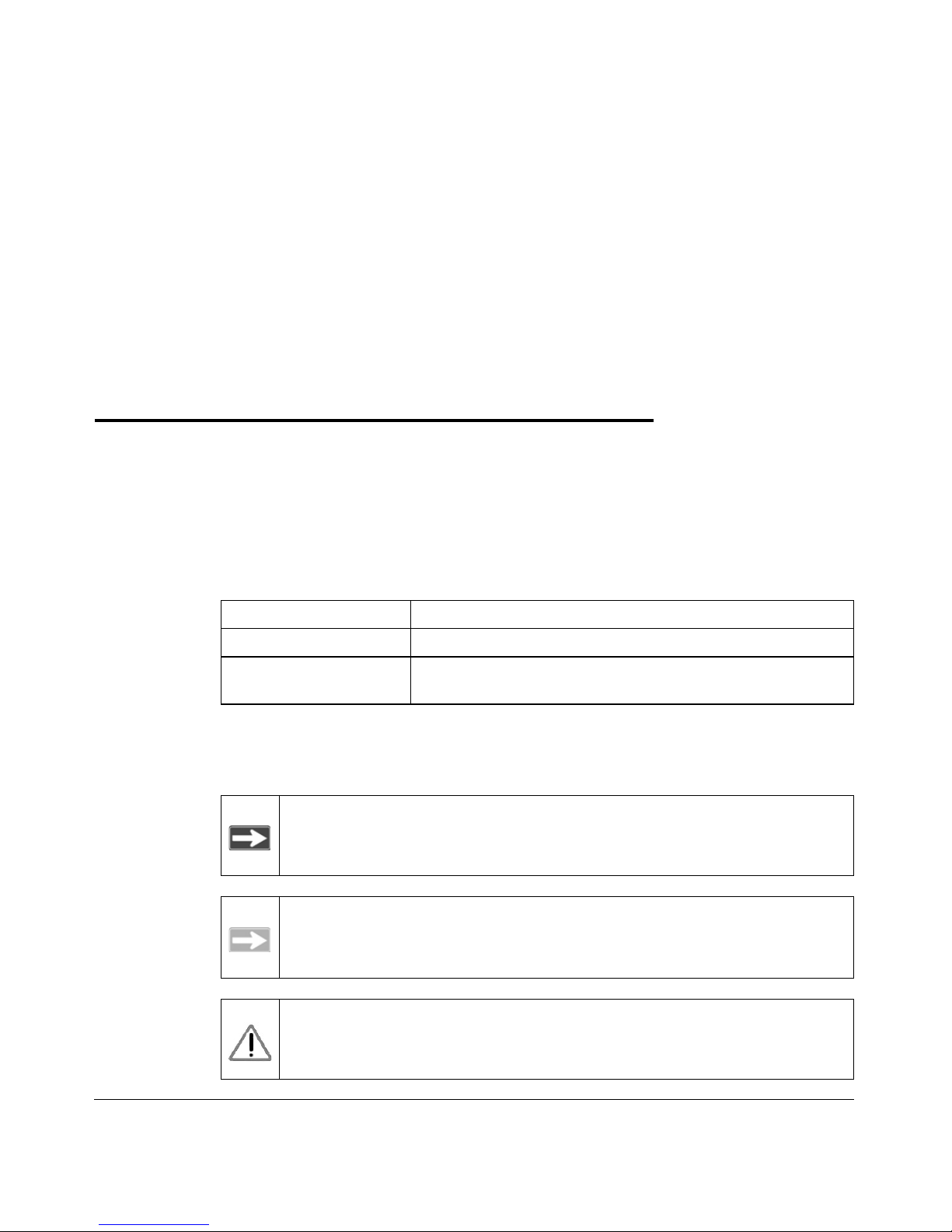
This guide uses the following formats to highlight special messages:
Table 1-1. Typographical Conventions
Italics Emphasis, books, CDs, URL names
Bold User input
Fixed
Screen text, file and server names, extensions, commands, IP
addresses
Note: This format is used to highlight information of importance or
special interest.
Tip: This format is used to highlight a procedure that will save time or
resources.
Warning: Ignoring this type of note may result in a malfunction or
damage to the equipment.
Managed Layer 2 Switches GSM7212, GSM7224, and GSM7248 Hardware Installation Guide
1-2 About This Manual
v1.0, March 2006
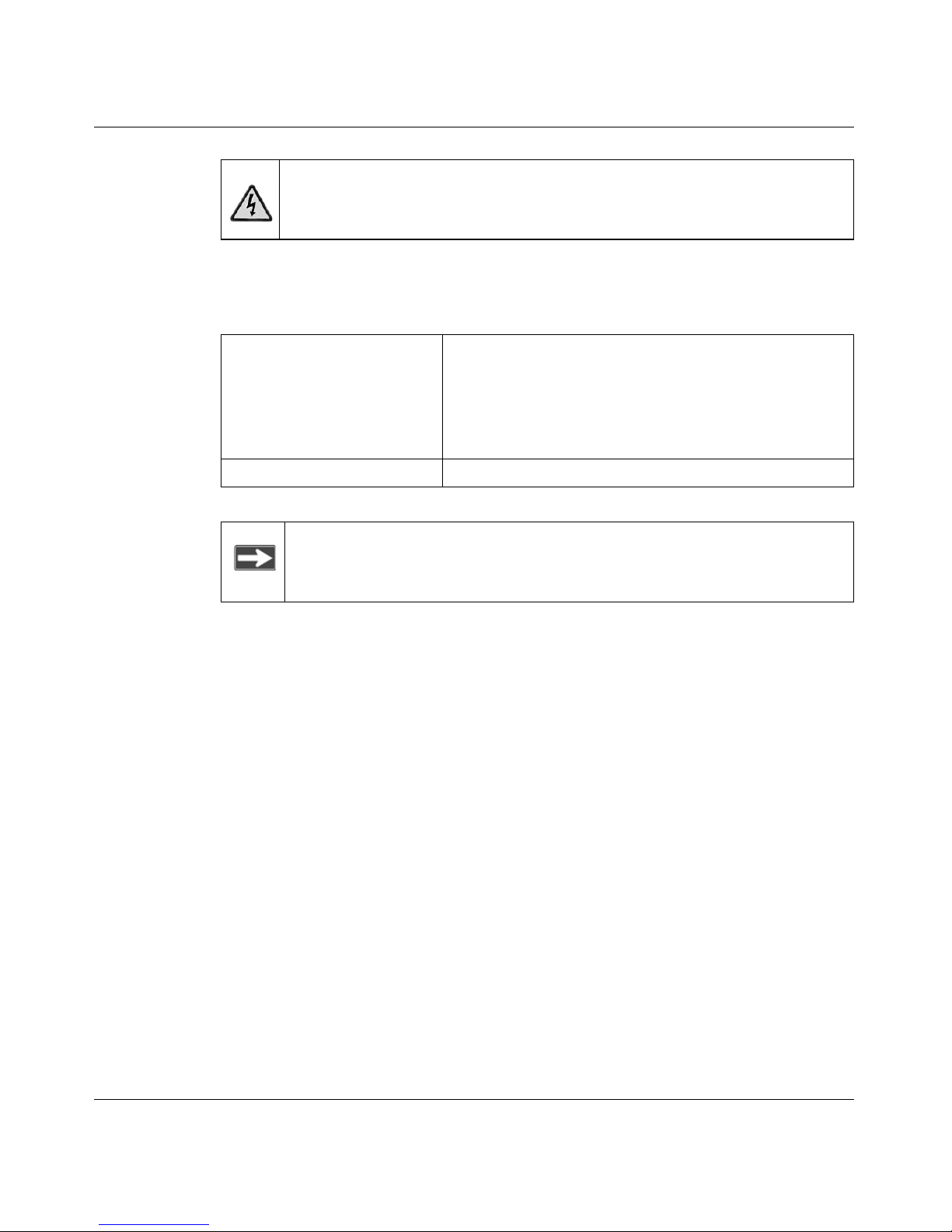
This manual is written according to these specifications:
Danger: This is a safety warning. Failure to take heed of this notice may
result in personal injury or death.
Table 1-2. Manual Scope
Product version • ProSafe 12-Port Gigabit L2 Managed Switch Model
GSM7212
• ProSafe 24-Port Gigabit L2 Managed Switch Model
GSM7224
• ProSafe 48-Port Gigabit L2 Managed Switch Model
GSM7248
Manual publication date March 2006
Note: Product updates are available on the NETGEAR, Inc. Web site at
http://kbserver.netgear.com.
Introduction 2-1
v1.0, March 2006
Chapter 2
Introduction
The NETGEAR Managed Layer 2 Switch is a state-of-the-art, high-performance,
IEEE-compliant network solution. It includes powerful managemen t features th at
you can use to eliminate bottlenecks, boost performance, and increase
productivity.
This guide describes the hardware for the following NETGEAR switches:
• ProSafe 12-Port Gigabit L2 Managed Switch Model GSM7212
• ProSafe 24-Port Gigabit L2 Managed Switch Model GSM7224
• ProSafe 48-Port Gigabit L2 Managed Switch Model GSM7248
These switches can be free-standing, or rack-mounted in a wiring closet or an
equipment room. For information about features for each product, see the
NETGEAR Web site at http://www.netgear.com.
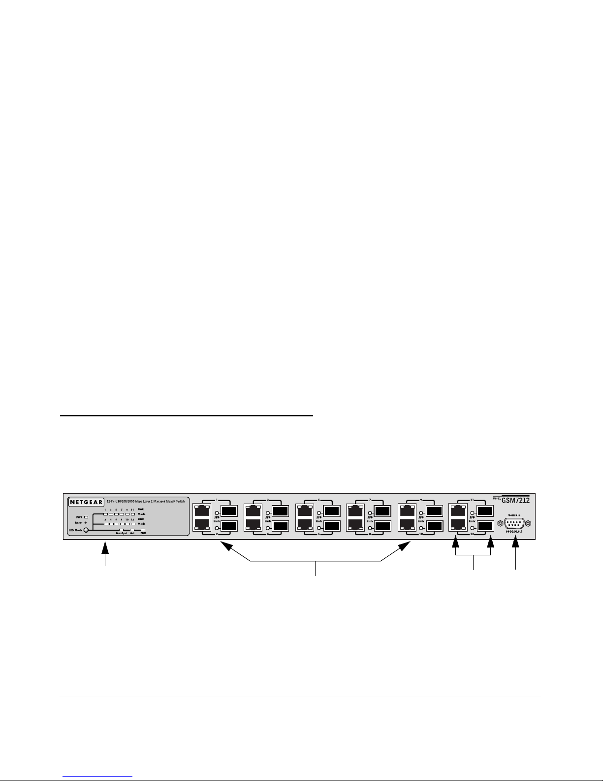
GSM7212 Front Panel and LEDs
The following figure shows the front panel of the GSM7212. It contains LEDs,
RJ-45 jacks, SFP module bays, and a console port.
Figure 2-1
ConsoleLEDs
RJ-45 jacks
SFP
port
module
bays
Managed Layer 2 Switches GSM7212, GSM7224, and GSM7248 Hardware Installation Guide
2-2 Introduction
v1.0, March 2006
The following table describes the LEDs on the front panel of the switch.
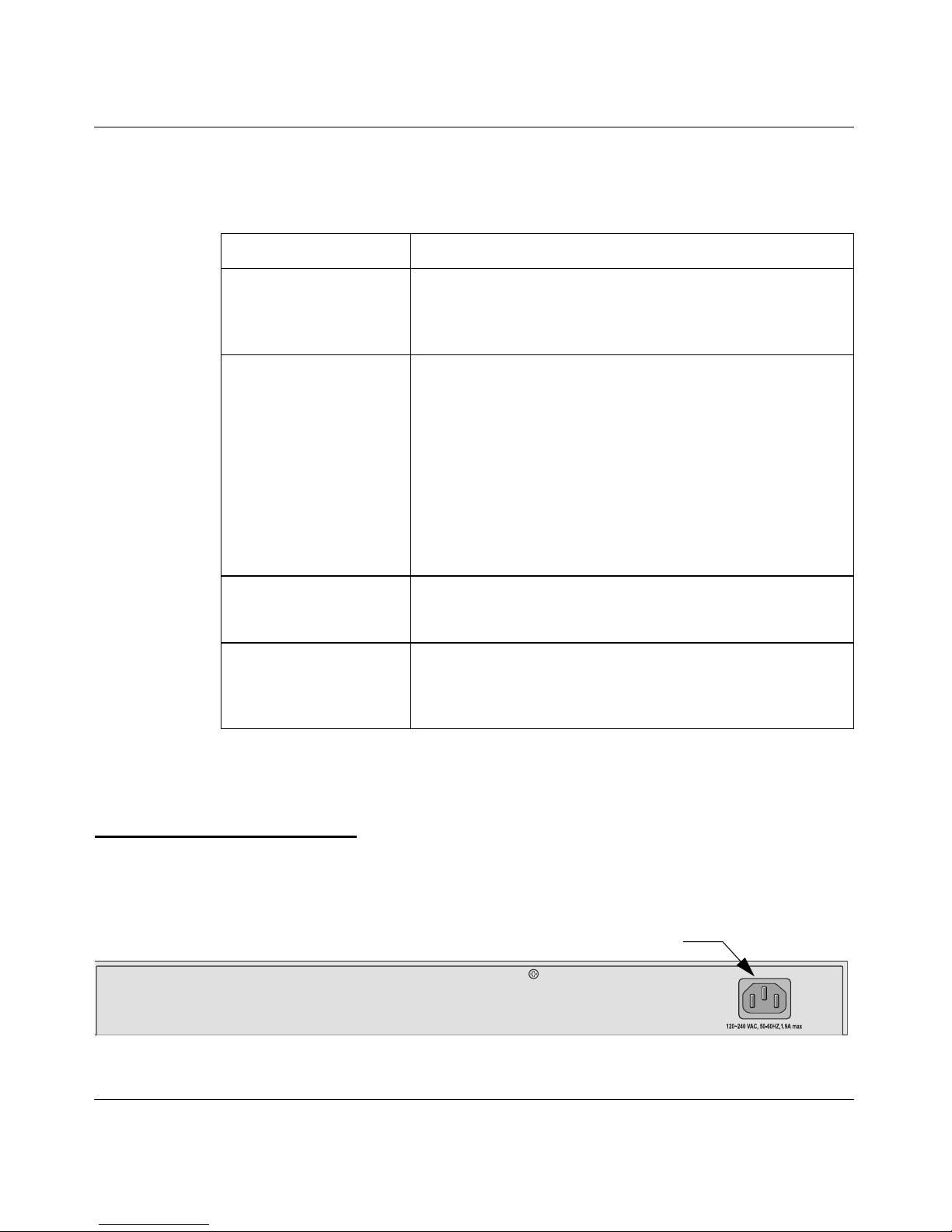
GSM7212 Rear Panel
The rear panel has a standard AC power receptacle for the supplied power cord.
Table 2-1. LED Descriptions for GSM7212
LED Description
Power • Green: Power is supplied, and the switch is operating
normally.
• Yellow: Power supply present, but it has failed.
• Off: Power is disconnected.
Mode
MaxSpd (maximum
speed), ACT (activity) or
FDX
MaxSpd (maximum speed)
• Green: Link in 1,000 Mbps.
• Yellow: Link in 100 Mbps.
• Off: Link in 10 Mbps.
ACT (activity)
• Blinking green: The port is sending or receiving packets.
FDX
• Green: Full-duplex mode.
• Yellow: Half-duplex mode.
• Blinking yellow: Collision occurred when sending and
receiving in half-duplex mode.
Link
(port number)
• Green: A valid 1,000 Mbps link is established on the port.
• Yellow: A valid 100 Mbps link is established on the port.
• Off: A valid 10 Mbps link is established on the port..
SFP Port
(1,000 Mbps only)
• Solid green: Link is up.
• Blinking green: The port is sending or receiving packets in
link up status.
• Off: No link is detected.
Figure 2-2
Power receptacle
Managed Layer 2 Switches GSM7212, GSM7224, and GSM7248 Hardware Installation Guide
Introduction 2-3
v1.0, March 2006
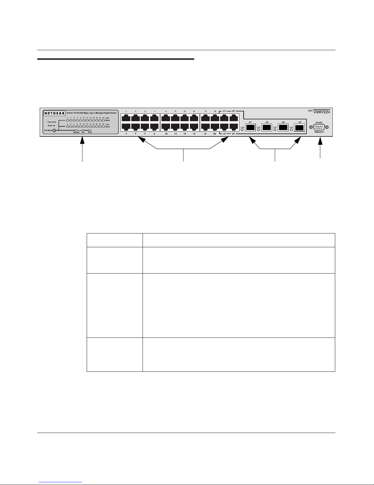
GSM7224 Front Panel and LEDs
The following figure shows the front panel of the GSM7224. The front panel
contains LEDs, RJ-45 jacks, and SFP module bays.
The following table shows the GSM7224 LEDs on the front of the switch.
Figure 2-3
Table 2-2. GSM7224 LED Description
LED Description
Power • Green: Power is supplied, and the switch is operating normally.
• Yellow: Power supply present, but it has failed.
• Off: Power is disconnected.
10/100/1000 ports
(two LEDs)
Speed (right)
• Green: Link in 1000 Mbps.
• Yellow: Link in 100 Mbps.
• Off: Link in 10 Mbps.
Link/ACT (left)
• Green: Link is up.
• Blinking green: The port is sending or receiving packets.
• Off: No link is detected.
SFP port
(1,000 Mbps only)
• Solid green: Link is up.
• Blinking green: The port is sending or receiving packets in link up
status.
• Off: No link is detected.
SFP
RJ-45 jacks
LEDs
module
bays
Console
port
Managed Layer 2 Switches GSM7212, GSM7224, and GSM7248 Hardware Installation Guide
2-4 Introduction
v1.0, March 2006
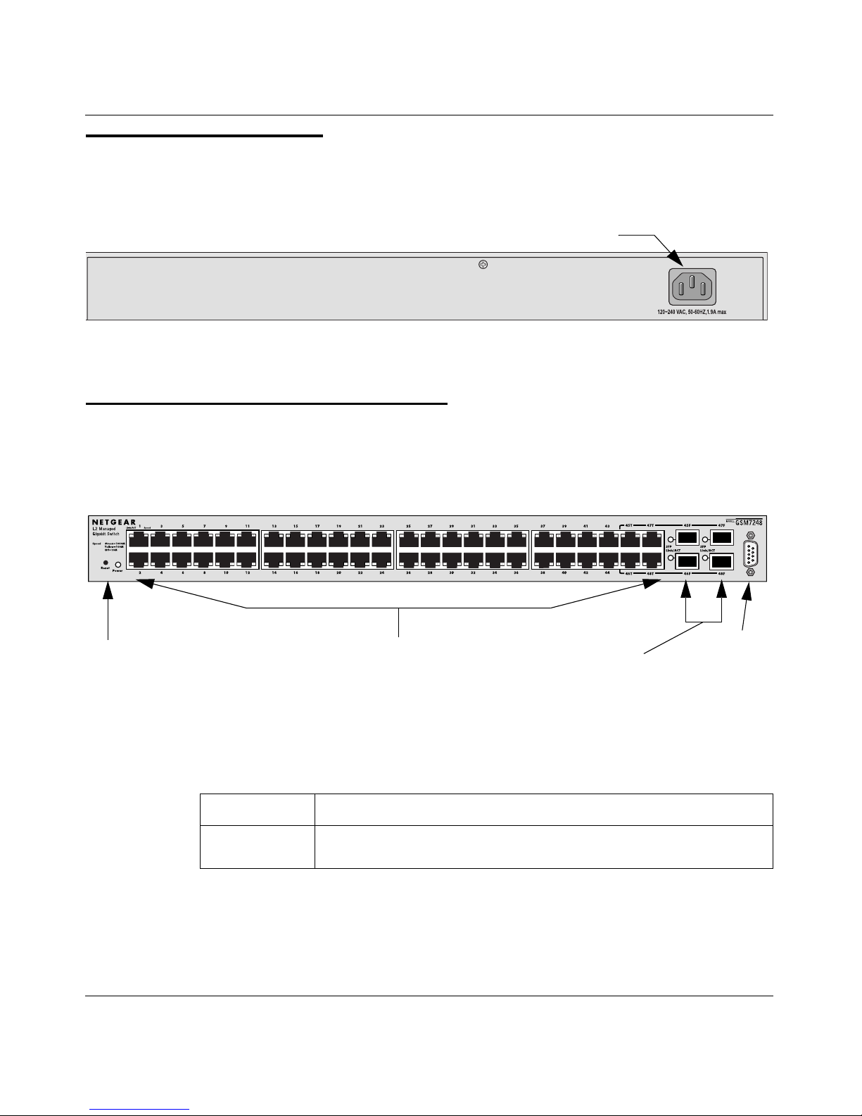
GSM7224 Rear Panel
The rear panel has a standard AC power receptacle for the supplied power cord.
GSM7248 Front Panel and LEDs
The following figure shows the front panel of the GSM7248. The front panel
contains LEDs, RJ-45 jacks, SFP module bays, and a console port.
The following table describes the GSM7248 LEDs on the front of the switch.
Figure 2-4
Figure 2-5
Table 2-3.
GSM7248 LED Description
LED Description
Power • Green: Power is supplied, and the switch is operating normall y.
• Off: No power is applied, or power failure.
Power receptacle
SFP
RJ-45 jacks
LEDs module
bays
Console
port
 Loading...