

Page 1

ProSafe Managed Switch
Command Line Interface (CLI)
User Manual
9.0.2
GSM5212P
GSM7212F
GSM7212P
GSM7224P
XSM7224S
350 East Plumeria Drive
San Jose, CA 95134
USA
November 2011
202-10936-01
1.0
Page 2

ProSafe Managed Switch
© 2011 NETGEAR, Inc. All rights reserved.
No part of this publication may be reproduced, transmitted, transcribed, stored in a retrieval system, or translated
into any language in any form or by any means without the written permission of NETGEAR, Inc.
Technical Support
Thank you for choosing NETGEAR. To register your product, get the latest product updates, or get support online,
visit us at http://support.netgear.com.
Phone (US & Canada only): 1-888-NETGEAR
Phone (Other Countries): See Support information card.
Trademarks
NETGEAR, the NETGEAR logo, ReadyNAS, ProSafe, Smart Wizard, Auto Uplink, X-RAID2, and NeoTV are
trademarks or registered trademarks of NETGEAR, Inc. Microsoft, Windows, Windows NT, and Vista are
registered trademarks of Microsoft Corporation. Other brand and product names are registered trademarks or
trademarks of their respective holders.
Statement of Conditions
To improve internal design, operational function, and/or reliability, NETGEAR reserves the right to make changes
to the products described in this document without notice. NETGEAR does not assume any liability that may occur
due to the use, or application of, the product(s) or circuit layout(s) described herein.
Revision History
Publication Part
Number
202-10936-01 1.0 November 2011 Add PoE and MVR mode features.
202-10515-05 1.1 June 2011 Add DHCPv6 and DHCPv6 mode features.
202-10515-04 1.0 November 2010 New document template.
202-10515-03 v 1.0 June 2010 Move some content to the Software Setup
202-10515-02 Software release 8.0.2: new firmware with
202-10515-01 Original publication.
Version Publish Date Comments
Guide.
DHCP L3 Relay, color conform policy, DHCP
server in dynamic mode, and configuring a
stacking port as an Ethernet port.
2
Page 3

Contents
Chapter 1 Using the Command-Line Interface
Chapter 2 Stacking Commands
Licensing and Command Support . . . . . . . . . . . . . . . . . . . . . . . . . . . . . . . .8
Command Syntax. . . . . . . . . . . . . . . . . . . . . . . . . . . . . . . . . . . . . . . . . . . .10
Command Conventions . . . . . . . . . . . . . . . . . . . . . . . . . . . . . . . . . . . . . . .11
Common Parameter Values. . . . . . . . . . . . . . . . . . . . . . . . . . . . . . . . . . . .11
Unit/Slot/Port Naming Convention . . . . . . . . . . . . . . . . . . . . . . . . . . . . . . .12
Using a Command’s “No” Form . . . . . . . . . . . . . . . . . . . . . . . . . . . . . . . . .13
Managed Switch Modules . . . . . . . . . . . . . . . . . . . . . . . . . . . . . . . . . . . . .13
Command Modes. . . . . . . . . . . . . . . . . . . . . . . . . . . . . . . . . . . . . . . . . . . .14
Command Completion and Abbreviation . . . . . . . . . . . . . . . . . . . . . . . . . .17
CLI Error Messages . . . . . . . . . . . . . . . . . . . . . . . . . . . . . . . . . . . . . . . . . .18
CLI Line-Editing Conventions. . . . . . . . . . . . . . . . . . . . . . . . . . . . . . . . . . .18
Using CLI Help . . . . . . . . . . . . . . . . . . . . . . . . . . . . . . . . . . . . . . . . . . . . . .19
Accessing the CLI. . . . . . . . . . . . . . . . . . . . . . . . . . . . . . . . . . . . . . . . . . . .20
Dedicated Port Stacking. . . . . . . . . . . . . . . . . . . . . . . . . . . . . . . . . . . . . . .21
Front Panel Stacking Commands. . . . . . . . . . . . . . . . . . . . . . . . . . . . . . . .29
Non-Stop Forwarding Commands . . . . . . . . . . . . . . . . . . . . . . . . . . . . . . .30
Stack Firmware Synchronization Commands. . . . . . . . . . . . . . . . . . . . . . .34
Chapter 3 Switching Commands
Port Configuration Commands. . . . . . . . . . . . . . . . . . . . . . . . . . . . . . . . . .38
Loopback Interface Commands . . . . . . . . . . . . . . . . . . . . . . . . . . . . . . . . .44
Spanning Tree Protocol (STP) Commands . . . . . . . . . . . . . . . . . . . . . . . .46
VLAN Commands. . . . . . . . . . . . . . . . . . . . . . . . . . . . . . . . . . . . . . . . . . . .63
Double VLAN Commands . . . . . . . . . . . . . . . . . . . . . . . . . . . . . . . . . . . . .76
Voice VLAN Commands. . . . . . . . . . . . . . . . . . . . . . . . . . . . . . . . . . . . . . .79
Provisioning (IEEE 802.1p) Commands. . . . . . . . . . . . . . . . . . . . . . . . . . .81
Protected Ports Commands . . . . . . . . . . . . . . . . . . . . . . . . . . . . . . . . . . . .81
Private Group Commands . . . . . . . . . . . . . . . . . . . . . . . . . . . . . . . . . . . . .84
GARP Commands . . . . . . . . . . . . . . . . . . . . . . . . . . . . . . . . . . . . . . . . . . .85
GVRP Commands . . . . . . . . . . . . . . . . . . . . . . . . . . . . . . . . . . . . . . . . . . .87
GMRP Commands . . . . . . . . . . . . . . . . . . . . . . . . . . . . . . . . . . . . . . . . . . .89
Port-Based Network Access Control Commands. . . . . . . . . . . . . . . . . . . .91
802.1X Supplicant Commands. . . . . . . . . . . . . . . . . . . . . . . . . . . . . . . . .105
Storm-Control Commands . . . . . . . . . . . . . . . . . . . . . . . . . . . . . . . . . . . .107
Port-Channel/LAG (802.3ad) Commands . . . . . . . . . . . . . . . . . . . . . . . .118
Port Mirroring . . . . . . . . . . . . . . . . . . . . . . . . . . . . . . . . . . . . . . . . . . . . . .134
3
Page 4

ProSafe Managed Switch
Static MAC Filtering . . . . . . . . . . . . . . . . . . . . . . . . . . . . . . . . . . . . . . . . .136
DHCP L2 Relay Agent Commands . . . . . . . . . . . . . . . . . . . . . . . . . . . . .140
DHCP Client Commands . . . . . . . . . . . . . . . . . . . . . . . . . . . . . . . . . . . . .144
DHCP Snooping Configuration Commands. . . . . . . . . . . . . . . . . . . . . . .145
Dynamic ARP Inspection Commands . . . . . . . . . . . . . . . . . . . . . . . . . . .154
IGMP Snooping Configuration Commands . . . . . . . . . . . . . . . . . . . . . . .161
IGMP Snooping Querier Commands . . . . . . . . . . . . . . . . . . . . . . . . . . . .169
MLD Snooping Commands . . . . . . . . . . . . . . . . . . . . . . . . . . . . . . . . . . .172
MLD Snooping Querier Commands. . . . . . . . . . . . . . . . . . . . . . . . . . . . .179
set mld querier . . . . . . . . . . . . . . . . . . . . . . . . . . . . . . . . . . . . . . . . . . .179
set mld querier query_interval . . . . . . . . . . . . . . . . . . . . . . . . . . . . . . .180
set mld querier timer expiry . . . . . . . . . . . . . . . . . . . . . . . . . . . . . . . . .180
set mld querier election participate. . . . . . . . . . . . . . . . . . . . . . . . . . . .181
show mldsnooping querier . . . . . . . . . . . . . . . . . . . . . . . . . . . . . . . . . .181
Port Security Commands . . . . . . . . . . . . . . . . . . . . . . . . . . . . . . . . . . . . .182
LLDP (802.1AB) Commands . . . . . . . . . . . . . . . . . . . . . . . . . . . . . . . . . .186
LLDP-MED Commands . . . . . . . . . . . . . . . . . . . . . . . . . . . . . . . . . . . . . .194
Denial of Service Commands. . . . . . . . . . . . . . . . . . . . . . . . . . . . . . . . . .203
MAC Database Commands . . . . . . . . . . . . . . . . . . . . . . . . . . . . . . . . . . .213
ISDP Commands . . . . . . . . . . . . . . . . . . . . . . . . . . . . . . . . . . . . . . . . . . .215
Priority-Based Flow Control Commands . . . . . . . . . . . . . . . . . . . . . . . . .220
Chapter 4 Multicast VLAN Registration (MVR)
About MVR. . . . . . . . . . . . . . . . . . . . . . . . . . . . . . . . . . . . . . . . . . . . . . . .223
MVR Commands . . . . . . . . . . . . . . . . . . . . . . . . . . . . . . . . . . . . . . . . . . .223
Chapter 5 Routing Commands
Address Resolution Protocol (ARP) Commands . . . . . . . . . . . . . . . . . . .232
IP Routing Commands. . . . . . . . . . . . . . . . . . . . . . . . . . . . . . . . . . . . . . .237
Router Discovery Protocol Commands . . . . . . . . . . . . . . . . . . . . . . . . . .250
Virtual LAN Routing Commands . . . . . . . . . . . . . . . . . . . . . . . . . . . . . . .253
Virtual Router Redundancy Protocol Commands. . . . . . . . . . . . . . . . . . .254
DHCP and BOOTP Relay Commands. . . . . . . . . . . . . . . . . . . . . . . . . . .263
IP Helper Commands. . . . . . . . . . . . . . . . . . . . . . . . . . . . . . . . . . . . . . . .265
Open Shortest Path First (OSPF) Commands . . . . . . . . . . . . . . . . . . . . .268
OSPF Graceful Restart Commands. . . . . . . . . . . . . . . . . . . . . . . . . . . . .305
nsf. . . . . . . . . . . . . . . . . . . . . . . . . . . . . . . . . . . . . . . . . . . . . . . . . . . . .306
nsf restart-interval. . . . . . . . . . . . . . . . . . . . . . . . . . . . . . . . . . . . . . . . .306
nsf helper . . . . . . . . . . . . . . . . . . . . . . . . . . . . . . . . . . . . . . . . . . . . . . .307
nsf helper disable . . . . . . . . . . . . . . . . . . . . . . . . . . . . . . . . . . . . . . . . . 307
nsf [ietf] helper strict-lsa-checking . . . . . . . . . . . . . . . . . . . . . . . . . . . .308
Routing Information Protocol (RIP) Commands. . . . . . . . . . . . . . . . . . . .308
ICMP Throttling Commands. . . . . . . . . . . . . . . . . . . . . . . . . . . . . . . . . . .316
Chapter 6 IP Multicast Commands
Multicast Commands . . . . . . . . . . . . . . . . . . . . . . . . . . . . . . . . . . . . . . . .318
4
Page 5

ProSafe Managed Switch
DVMRP Commands. . . . . . . . . . . . . . . . . . . . . . . . . . . . . . . . . . . . . . . . .324
PIM Commands . . . . . . . . . . . . . . . . . . . . . . . . . . . . . . . . . . . . . . . . . . . .329
Internet Group Message Protocol (IGMP) Commands. . . . . . . . . . . . . . .340
IGMP Proxy Commands. . . . . . . . . . . . . . . . . . . . . . . . . . . . . . . . . . . . . .347
Chapter 7 IPv6 Commands
Tunnel Interface Commands . . . . . . . . . . . . . . . . . . . . . . . . . . . . . . . . . .354
IPv6 Routing Commands . . . . . . . . . . . . . . . . . . . . . . . . . . . . . . . . . . . . .355
OSPFv3 Commands. . . . . . . . . . . . . . . . . . . . . . . . . . . . . . . . . . . . . . . . .376
OSPFv3 Graceful Restart Commands . . . . . . . . . . . . . . . . . . . . . . . . . . .407
DHCPv6 Commands . . . . . . . . . . . . . . . . . . . . . . . . . . . . . . . . . . . . . . . .409
Chapter 8 IPv6 Multicast Commands
IPv6 Multicast Forwarder Commands . . . . . . . . . . . . . . . . . . . . . . . . . . .418
IPv6 PIM Commands . . . . . . . . . . . . . . . . . . . . . . . . . . . . . . . . . . . . . . . .420
IPv6 MLD Commands . . . . . . . . . . . . . . . . . . . . . . . . . . . . . . . . . . . . . . .428
IPv6 MLD-Proxy Commands . . . . . . . . . . . . . . . . . . . . . . . . . . . . . . . . . .434
Chapter 9 Quality of Service (QoS) Commands
Class of Service (CoS) Commands . . . . . . . . . . . . . . . . . . . . . . . . . . . . .440
Differentiated Services (DiffServ) Commands . . . . . . . . . . . . . . . . . . . . .448
DiffServ Class Commands . . . . . . . . . . . . . . . . . . . . . . . . . . . . . . . . . . . .449
DiffServ Policy Commands. . . . . . . . . . . . . . . . . . . . . . . . . . . . . . . . . . . .457
DiffServ Service Commands . . . . . . . . . . . . . . . . . . . . . . . . . . . . . . . . . .463
DiffServ Show Commands . . . . . . . . . . . . . . . . . . . . . . . . . . . . . . . . . . . .464
MAC Access Control List (ACL) Commands . . . . . . . . . . . . . . . . . . . . . .470
IP Access Control List (ACL) Commands. . . . . . . . . . . . . . . . . . . . . . . . .474
IPv6 Access Control List (ACL) Commands. . . . . . . . . . . . . . . . . . . . . . .481
Time Range Commands for Time-Based ACLs. . . . . . . . . . . . . . . . . . . .485
Auto-Voice over IP Commands . . . . . . . . . . . . . . . . . . . . . . . . . . . . . . . .488
Chapter 10 Power over Ethernet (PoE) Commands
About PoE . . . . . . . . . . . . . . . . . . . . . . . . . . . . . . . . . . . . . . . . . . . . . . . .490
PoE Commands . . . . . . . . . . . . . . . . . . . . . . . . . . . . . . . . . . . . . . . . . . . .491
Chapter 11 Utility Commands
Auto Install Commands . . . . . . . . . . . . . . . . . . . . . . . . . . . . . . . . . . . . . .502
Dual Image Commands . . . . . . . . . . . . . . . . . . . . . . . . . . . . . . . . . . . . . .504
System Information and Statistics Commands. . . . . . . . . . . . . . . . . . . . .506
Logging Commands . . . . . . . . . . . . . . . . . . . . . . . . . . . . . . . . . . . . . . . . .516
Email Alerting and Mail Server Commands . . . . . . . . . . . . . . . . . . . . . . .520
System Utility and Clear Commands . . . . . . . . . . . . . . . . . . . . . . . . . . . .527
Simple Network Time Protocol (SNTP) Commands. . . . . . . . . . . . . . . . .536
DHCP Server Commands . . . . . . . . . . . . . . . . . . . . . . . . . . . . . . . . . . . .543
DNS Client Commands . . . . . . . . . . . . . . . . . . . . . . . . . . . . . . . . . . . . . .555
5
Page 6

ProSafe Managed Switch
Packet Capture Commands. . . . . . . . . . . . . . . . . . . . . . . . . . . . . . . . . . .560
Serviceability Packet Tracing Commands . . . . . . . . . . . . . . . . . . . . . . . .561
Cable Test Command . . . . . . . . . . . . . . . . . . . . . . . . . . . . . . . . . . . . . . .579
sFlow Commands. . . . . . . . . . . . . . . . . . . . . . . . . . . . . . . . . . . . . . . . . . .579
Software License Commands . . . . . . . . . . . . . . . . . . . . . . . . . . . . . . . . .584
IP Address Conflict Commands . . . . . . . . . . . . . . . . . . . . . . . . . . . . . . . .585
Link Local Protocol Filtering Commands . . . . . . . . . . . . . . . . . . . . . . . . .586
Chapter 12 Management Commands
Configuring the Switch Management CPU. . . . . . . . . . . . . . . . . . . . . . . .589
Network Interface Commands . . . . . . . . . . . . . . . . . . . . . . . . . . . . . . . . .591
Console Port Access Commands. . . . . . . . . . . . . . . . . . . . . . . . . . . . . . .594
Telnet Commands . . . . . . . . . . . . . . . . . . . . . . . . . . . . . . . . . . . . . . . . . .596
Secure Shell (SSH) Commands. . . . . . . . . . . . . . . . . . . . . . . . . . . . . . . .601
Management Security Commands. . . . . . . . . . . . . . . . . . . . . . . . . . . . . .604
Hypertext Transfer Protocol (HTTP) Commands . . . . . . . . . . . . . . . . . . .605
Access Commands . . . . . . . . . . . . . . . . . . . . . . . . . . . . . . . . . . . . . . . . .612
User Account Commands . . . . . . . . . . . . . . . . . . . . . . . . . . . . . . . . . . . .612
SNMP Commands . . . . . . . . . . . . . . . . . . . . . . . . . . . . . . . . . . . . . . . . . .628
RADIUS Commands . . . . . . . . . . . . . . . . . . . . . . . . . . . . . . . . . . . . . . . .639
TACACS+ Commands . . . . . . . . . . . . . . . . . . . . . . . . . . . . . . . . . . . . . . . 651
Configuration Scripting Commands . . . . . . . . . . . . . . . . . . . . . . . . . . . . .655
Pre-login Banner and System Prompt Commands . . . . . . . . . . . . . . . . .657
Switch Database Management (SDM) Templates. . . . . . . . . . . . . . . . . .658
IPv6 Management Commands. . . . . . . . . . . . . . . . . . . . . . . . . . . . . . . . .659
Chapter 13 Log Messages
Core . . . . . . . . . . . . . . . . . . . . . . . . . . . . . . . . . . . . . . . . . . . . . . . . . . . . .665
Utilities . . . . . . . . . . . . . . . . . . . . . . . . . . . . . . . . . . . . . . . . . . . . . . . . . . .667
Management . . . . . . . . . . . . . . . . . . . . . . . . . . . . . . . . . . . . . . . . . . . . . .669
Switching . . . . . . . . . . . . . . . . . . . . . . . . . . . . . . . . . . . . . . . . . . . . . . . . .673
QoS . . . . . . . . . . . . . . . . . . . . . . . . . . . . . . . . . . . . . . . . . . . . . . . . . . . . .679
Routing/IPv6 Routing . . . . . . . . . . . . . . . . . . . . . . . . . . . . . . . . . . . . . . . .680
Multicast. . . . . . . . . . . . . . . . . . . . . . . . . . . . . . . . . . . . . . . . . . . . . . . . . .683
Stacking . . . . . . . . . . . . . . . . . . . . . . . . . . . . . . . . . . . . . . . . . . . . . . . . . .685
Technologies . . . . . . . . . . . . . . . . . . . . . . . . . . . . . . . . . . . . . . . . . . . . . .686
O/S Support . . . . . . . . . . . . . . . . . . . . . . . . . . . . . . . . . . . . . . . . . . . . . . .688
Chapter 14 Captive Portal Commands
Captive Portal Global Commands . . . . . . . . . . . . . . . . . . . . . . . . . . . . . .690
Captive Portal Configuration Commands. . . . . . . . . . . . . . . . . . . . . . . . .694
Captive Portal Status Commands . . . . . . . . . . . . . . . . . . . . . . . . . . . . . .700
Captive Portal Client Connection Commands . . . . . . . . . . . . . . . . . . . . .704
Captive Portal Interface Commands . . . . . . . . . . . . . . . . . . . . . . . . . . . .708
Captive Portal Local User Commands. . . . . . . . . . . . . . . . . . . . . . . . . . .709
Captive Portal User Group Commands . . . . . . . . . . . . . . . . . . . . . . . . . .715
6
Page 7

ProSafe Managed Switch
Chapter 15 Command List
Index
7
Page 8

1. Using the Command-Line Interface
The command-line interface (CLI) is a text-based way to manage and monitor the system.
You can access the CLI by using a direct serial connection or by using a remote logical
connection with telnet or SSH.
This chapter describes the CLI syntax, conventions, and modes. It contains the following
sections:
• Licensing and Command Support
• Command Syntax
• Command Conventions
• Common Parameter Values
• Unit/Slot/Port Naming Convention
• Using a Command’s “No” Form
• Managed Switch Modules
• Command Modes
• Command Completion and Abbreviation
• CLI Error Messages
• CLI Line-Editing Conventions
• Using CLI Help
• Accessing the CLI
1
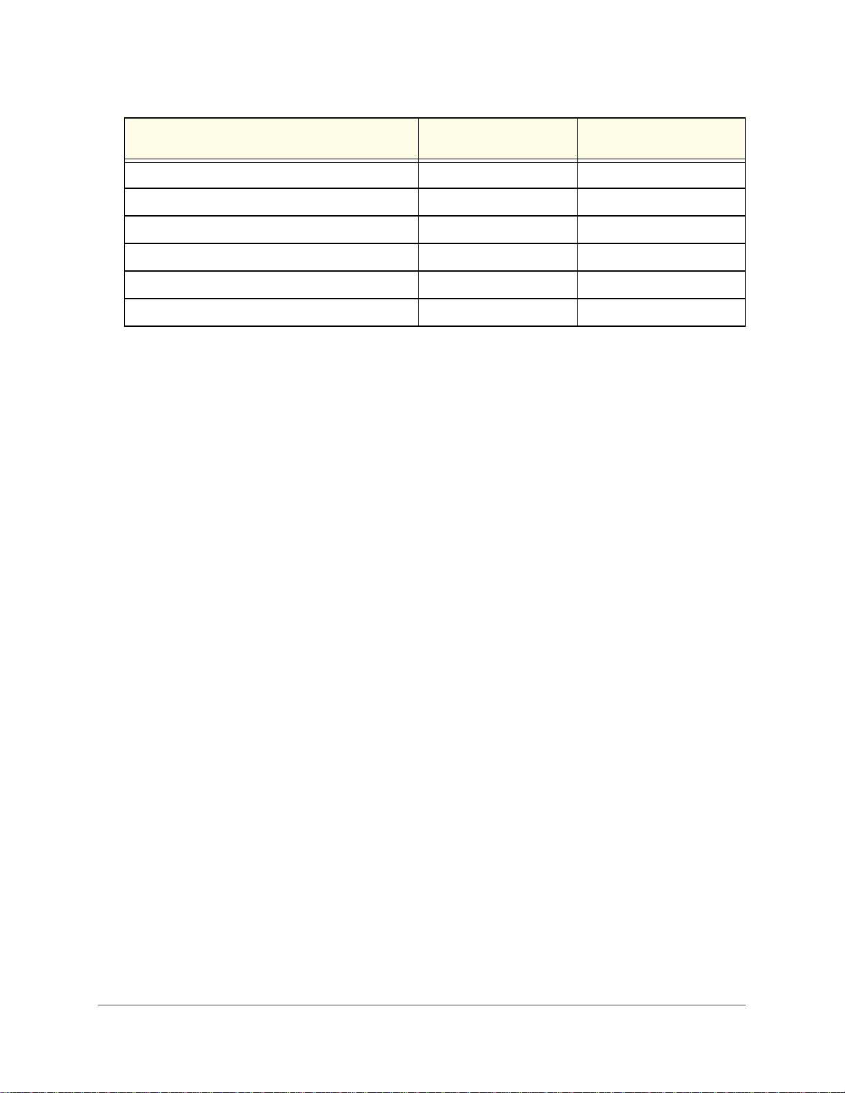
Licensing and Command Support
As shown in the following table, some command groups or commands require a license and
some are supported on particular switch models. For those requiring a license, license keys
8
Page 9

ProSafe Managed Switch
are available from your VAR or NETGEAR authorized e-commerce portal. License activation
is described in the Software Setup Manual.
Command Group or Command XSM7224S GSM7212F/GSM7212P/
GSM7224P/GSM5212P
Front Panel Stacking Commands Supported Not supported
Non-Stop Forwarding Commands Supported Not supported
Stack Firmware Synchronization Commands Supported Not supported
Router Discovery Protocol Commands Require license Not supported
Virtual Router Redundancy Protocol Commands Require license Not supported
Open Shortest Path First (OSPF) Commands Require license Not supported
OSPF Graceful Restart Commands Require license Not supported
Routing Information Protocol (RIP) Commands Require license Not supported
Tunnel Interface Commands Require license Not supported
IPv6 Routing Commands Require license Not supported
OSPFv3 Commands Require license Not supported
OSPFv3 Graceful Restart Commands Require license Not supported
DHCPv6 Commands Require license Not supported
Multicast Commands Require license Not supported
DVMRP Commands Require license Not supported
PIM Commands Require license Not supported
Internet Group Message Protocol (IGMP)
Commands
IGMP Proxy Commands Require license Not supported
IPv6 Multicast Forwarder Commands Require license Not supported
IPv6 PIM Commands Require license Not supported
IPv6 MLD Commands Require license Not supported
IPv6 MLD-Proxy Commands Require license Not supported
PoE Commands Not supported Supported
Require license Not supported
MVR Commands Not supported Supported
Link Local Protocol Filtering Commands Supported Not supported
Priority-Based Flow Control Commands Supported Not supported
Captive Portal Commands Supported Not supported
Using the Command-Line Interface
9
Page 10
ProSafe Managed Switch
Command Group or Command XSM7224S GSM7212F/GSM7212P/
GSM7224P/GSM5212P
cos-queue random-detect Supported Not supported
no cos-queue random-detect Supported Not supported
random-detect exponential weighting-constant Supported Not supported
no random-detect exponential weighting-constant Supported Not supported
random-detect queue-parms Supported Not supported
no random-detect queue-parms Supported Not supported
Command Syntax
A command is one or more words that might be followed by one or more parameters.
Parameters can be required or optional values.
Some commands, such as show network or clear vlan, do not require parameters.
Other commands, such as network parms, require that you supply a value after the
command. You must type the parameter values in a specific order, and optional parameters
follow required parameters. The following example describes the network parms
command syntax:
Format network parms <ipaddr> <netmask> [gateway]
• network parms is the command name.
• <ipaddr> and <netmask> are parameters and represent required values that you must
enter after you type the command keywords.
• [gateway] is an optional parameter, so you are not required to enter a value in place of
the parameter.
The New Template User Manual lists each command by the command name and provides a
brief description of the command. Each command reference also contains the following
information:
• Format shows the command keywords and the required and optional parameters.
• Mode identifies the command mode you must be in to access the command.
• Default shows the default value, if any, of a configurable setting on the device.
The show commands also contain a description of the information that the command shows.
Using the Command-Line Interface
10
Page 11

ProSafe Managed Switch
Command Conventions
In this document, the command name is in bold font. Parameters are in italic font. You
must replace the parameter name with an appropriate value, which might be a name or
number. Parameters are order dependent.
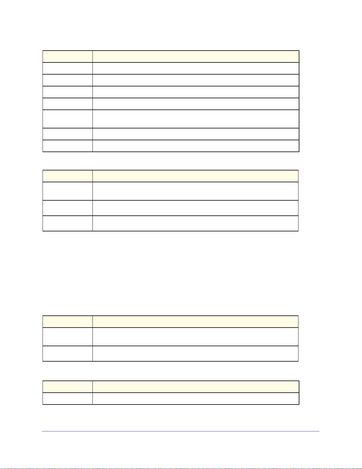
The parameters for a command might include mandatory values, optional values, or keyword
choices. Table 1 describes the conventions this document uses to distinguish between value
types.
Table 1. Parameter Conventions
Symbol Example Description
<> angle brackets
[] square brackets Indicates an optional parameter that you can enter in
{} curly braces Indicates that you must select a parameter from the list of
| Vertical bars Separates the mutually exclusive choices.
[{}] Braces within
square brackets
<value>
[value]
{choice1 |
choice2}
choice1 | choice2
[{choice1 |
choice2}]
Indicates that you must enter a value in place of the
brackets and text inside them.
place of the brackets and text inside them.
choices.
Indicates a choice within an optional element.
Common Parameter Values
Parameter values might be names (strings) or numbers. To use spaces as part of a name
parameter, enclose the name value in double quotes. For example, the expression “System
Using the Command-Line Interface
11
Page 12

ProSafe Managed Switch
Name with Spaces” forces the system to accept the spaces. Empty strings (““) are not valid
user-defined strings. Table 2 describes common parameter values and value formatting.
Table 2. Parameter Descriptions
Parameter Description
ipaddr This parameter is a valid IP address. You can enter the IP address in the following formats:
a (32 bits)
a.b (8.24 bits)
a.b.c (8.8.16 bits)
a.b.c.d (8.8.8.8)
In addition to these formats, the CLI accepts decimal, hexadecimal and octal formats
through the following input formats (where n is any valid hexadecimal, octal or decimal
number):
0xn (CLI assumes hexadecimal format)
0n (CLI assumes octal format with leading zeros)
n (CLI assumes decimal format)
ipv6-address
FE80:0000:0000:0000:020F:24FF:FEBF:DBCB, or
FE80:0:0:0:20F:24FF:FEBF:DBCB, or
FE80::20F24FF:FEBF:DBCB, or
FE80:0:0:0:20F:24FF:128:141:49:32
For additional information, refer to RFC 3513.
Interface or
unit/slot/port
Logical Interface
Character strings Use double quotation marks to identify character strings, for example, “System Name with
Valid slot and port number separated by forward slashes. For example, 0/1 represents slot
number 0 and port number 1.
Represents a logical slot and port number. This is applicable in the case of a port-channel
(LAG). You can use the logical unit/slot/port to configure the port-channel.
Spaces”. An empty string (“”) is not valid.
Unit/Slot/Port Naming Convention
Managed switch software references physical entities such as cards and ports by using a
unit/slot/port naming convention. The software also uses this convention to identify certain
logical entities, such as Port-Channel interfaces.
The slot number has two uses. In the case of physical ports, it identifies the card containing
the ports. In the case of logical and CPU ports it also identifies the type of interface or port.
Table 3. Type of Slots
Slot Type Description
Physical slot numbers Physical slot numbers begin with zero, and are allocated up to the maximum
number of physical slots.
Logical slot numbers Logical slots immediately follow physical slots and identify port-channel (LAG) or
router interfaces.
CPU slot numbers The CPU slots immediately follow the logical slots.
Using the Command-Line Interface
12
Page 13

ProSafe Managed Switch
The port identifies the specific physical port or logical interface being managed on a given
slot.
Table 4. Type of Ports
Port Type Description
Physical Ports The physical ports for each slot are numbered sequentially starting from zero.
Logical Interfaces Port-channel or Link Aggregation Group (LAG) interfaces are logical interfaces
that are only used for bridging functions.
VLAN routing interfaces are only used for routing functions.
Loopback interfaces are logical interfaces that are always up.
Tunnel interfaces are logical point-to-point links that carry encapsulated packets.
CPU ports CPU ports are handled by the driver as one or more physical entities located on
physical slots.
Note: In the CLI, loopback and tunnel interfaces do not use the
unit/slot/port format. To specify a loopback interface, you use the
loopback ID. To specify a tunnel interface, you use the tunnel ID.
Using a Command’s “No” Form
The no keyword is a specific form of an existing command and does not represent a new or
distinct command. Almost every configuration command has a no form. In general, use the
no form to reverse the action of a command or reset a value back to the default. For
example, the no shutdown configuration command reverses the shutdown of an interface.
Use the command without the keyword no to re-enable a disabled feature or to enable a
feature that is disabled by default. Only the configuration commands are available in the no
form.
Managed Switch Modules
Managed switch software consists of flexible modules that can be applied in various
combinations to develop advanced Layer 2/3/4+ products. The commands and command
modes available on your switch depend on the installed modules. Additionally, for some
show commands, the output fields might change based on the modules included in the
software.
The software suite includes the following modules:
• Switching (Layer 2)
• Routing (Layer 3)
• IPv6—IPv6 routing
• Multicast
Using the Command-Line Interface
13
Page 14

ProSafe Managed Switch
• Quality of Service
• Management (CLI, Web UI, and SNMP)
• IPv6 Management—Allows management of the device through an IPv6 through an IPv6
address without requiring the IPv6 Routing package in the system. The management
address can be associated with the network port (front-panel switch ports) and a routine
interface (port or VLAN).
• Stacking
Not all modules are available for all platforms or software releases.
Command Modes
The CLI groups commands into modes according to the command function. Each of the
command modes supports specific software commands. The commands in one mode are not
available until you switch to that particular mode, with the exception of the User EXEC mode
commands. You can execute the User EXEC mode commands in the Privileged EXEC mode.
The command prompt changes in each command mode to help you identify the current
mode.
Table 5 describes the command modes and the prompts visible in that mode.
Note: The command modes available on your switch depend on the
software modules that are installed. For example, a switch that does
not support BGPv4 does not have the Router BGPv4 Command
Mode.
Table 5. CLI Command Modes
Command Mode Prompt Mode Description
User EXEC
Privileged EXEC
Global Config
VLAN Config
Switch>
Switch#
Switch (Config)#
Switch (Vlan)#
Contains a limited set of commands to view
basic system information.
Allows you to issue any EXEC command, enter
the VLAN mode, or enter the Global
Configuration mode.
Groups general setup commands and permits
you to make modifications to the running
configuration.
Groups all the VLAN commands.
Using the Command-Line Interface
14
Page 15

ProSafe Managed Switch
Table 5. CLI Command Modes (Continued)
Command Mode Prompt Mode Description
Interface Config Switch (Interface <unit/slot/port>)#
Switch (Interface Loopback <id>)#
Switch (Interface Tunnel <id>)#
Line Config Switch (line)# Contains commands to configure outbound
Policy Map
Config
Policy Class
Config
Class Map Config Switch (Config-class-map)# Contains the QoS class map configuration
Ipv6_Class-Map
Config
Router OSPF
Config
Router OSPFv3
Config
Switch (Config-policy-map)# Contains the QoS Policy-Map configuration
Switch (Config-policy-class-map)# Consists of class creation, deletion, and
Switch (Config-class-map)# Contains the QoS class map configuration
Switch (Config-router)# Contains the OSPF configuration commands.
Switch (Config rtr)# Contains the OSPFv3 configuration commands.
Manages the operation of an interface and
provides access to the router interface
configuration commands.
Use this mode to set up a physical port for a
specific logical connection operation.
telnet settings and console interface settings.
commands.
matching commands. The class match
commands specify Layer 2, Layer 3, and
general match criteria.
commands for IPv4.
commands for IPv6.
Router RIP Config Switch (Config-router)# Contains the RIP configuration commands.
MAC Access-list
Config
TACACS Config Switch (Tacacs)# Contains commands to configure properties for
DHCP Pool
Config
DHCPv6 Pool
Config
Stack Global
Config Mode
ARP Access-List
Config Mode
Switch (Config-mac-access-list)# Allows you to create a MAC Access-List and to
enter the mode containing MAC Access-List
configuration commands.
the TACACS servers.
Switch (Config dhcp-pool)# Contains the DHCP server IP address pool
configuration commands.
Switch (Config dhcp6-pool)# Contains the DHCPv6 server IPv6 address pool
configuration commands.
Switch (Config stack)# Allows you to access the Stack Global Config
Mode.
Switch (Config-arp-access-list)# Contains commands to add ARP ACL rules in
an ARP Access List.
Using the Command-Line Interface
15
Page 16

ProSafe Managed Switch
Table 6 explains how to enter or exit each mode.
Table 6. CLI Mode Access and Exit
Command Mode Access Method Exit or Access Previous Mode
User EXEC This is the first level of access. To exit, enter logout.
Privileged EXEC From the User EXEC mode, enter
enable.
Global Config From the Privileged EXEC mode,
enter configure.
VLAN Config From the Privileged EXEC mode,
enter vlan database.
Interface Config From the Global Config mode,
enter
interface <unit/slot/port>
or interface loopback <id>
or interface tunnel <id>
Line Config From the Global Config mode,
enter
lineconfig.
Policy-Map
Config
Policy-Class-Map
Config
Class-Map
Config
From the Global Config mode,
enter
policy-map <name> in.
From the Policy Map mode enter
class.
From the Global Config mode,
enter
class-map, and specify the
optional keyword ipv4 to specify
the Layer 3 protocol for this class.
See class-map on page 449 for
more information.
To exit to the User EXEC mode, enter exit or
press Ctrl-Z.
To exit to the Privileged EXEC mode, enter exit,
or press Ctrl-Z.
To exit to the Privileged EXEC mode, enter exit,
or press Ctrl-Z.
To exit to the Global Config mode, enter exit. To
return to the Privileged EXEC mode, enter
Ctrl-Z.
To exit to the Global Config mode, enter exit. To
return to the Privileged EXEC mode, enter
Ctrl-Z.
To exit to the Global Config mode, enter exit. To
return to the Privileged EXEC mode, enter
Ctrl-Z.
To exit to the Policy Map mode, enter exit. To
return to the Privileged EXEC mode, enter
Ctrl-Z.
To exit to the Global Config mode, enter exit. To
return to the Privileged EXEC mode, enter
Ctrl-Z.
Ipv6-Class-Map
Config
Router OSPF
Config
Router OSPFv3
Config
From the Global Config mode,
enter
class-map and specify the
optional keyword ipv6 to specify
the Layer 3 protocol for this class.
See class-map on page 449 for
more information.
From the Global Config mode,
enter
router ospf.
From the Global Config mode,
enter
ipv6 router ospf.
To exit to the Global Config mode, enter exit. To
return to the Privileged EXEC mode, enter
Ctrl-Z.
To exit to the Global Config mode, enter exit. To
return to the Privileged EXEC mode, enter
Ctrl-Z.
To exit to the Global Config mode, enter exit. To
return to the Privileged EXEC mode, enter
Ctrl-Z.
Using the Command-Line Interface
16
Page 17

ProSafe Managed Switch
Table 6. CLI Mode Access and Exit (Continued)
Command Mode Access Method Exit or Access Previous Mode
Router RIP
Config
MAC Access-list
Config
TACACS Config From the Global Config mode,
DHCP Pool
Config
DHCPv6 Pool
Config
Stack Global
Config Mode
ARP Access-List
Config Mode
From the Global Config mode,
enter
router rip.
From the Global Config mode,
enter
mac access-list extended
<name>.
enter tacacs-server host
<ip-addr>, where <ip-addr> is
the IP address of the TACACS
server on your network.
From the Global Config mode,
enter
ip dhcp pool <pool-name>.
From the Global Config mode,
enter
ip dhcpv6 pool <pool-name>.
From the Global Config mode,
enter the stack command.
From the Global Config mode,
enter the
command.
arp access-list
To exit to the Global Config mode, enter exit. To
return to the Privileged EXEC mode, enter
Ctrl-Z.
To exit to the Global Config mode, enter exit. To
return to the Privileged EXEC mode, enter
Ctrl-Z.
To exit to the Global Config mode, enter exit. To
return to the Privileged EXEC mode, enter
Ctrl-Z.
To exit to the Global Config mode, enter exit. To
return to the Privileged EXEC mode, enter
Ctrl-Z.
To exit to the Global Config mode, enter exit. To
return to the Privileged EXEC mode, enter
Ctrl-Z.
To exit to the Global Config mode, enter the exit
command. To return to the Privileged EXEC
mode, enter Ctrl-Z.
To exit to the Global Config mode, enter the
exit command. To return to the Privileged
EXEC mode, enter
Ctrl-Z.
Command Completion and Abbreviation
Command completion finishes spelling the command when you type enough letters of a
command to uniquely identify the command keyword. Once you have entered enough letters,
press the SPACEBAR or TAB key to complete the word.
Command abbreviation allows you to execute a command when you have entered there are
enough letters to uniquely identify the command. You must enter all of the required keywords
and parameters before you enter the command.
Using the Command-Line Interface
17
Page 18

ProSafe Managed Switch
CLI Error Messages
If you enter a command and the system is unable to execute it, an error message appears.
Table 7 describes the most common CLI error messages.
Table 7. CLI Error Messages
Message Text Description
% Invalid input detected at '^' marker. Indicates that you entered an incorrect or unavailable command.
The carat (^) shows where the invalid text is detected. This
message also appears if any of the parameters or values are not
recognized.
Command not found / Incomplete
command. Use ? to list commands.
Ambiguous command Indicates that you did not enter enough letters to uniquely identify
Indicates that you did not enter the required keywords or values.
the command.
CLI Line-Editing Conventions
Table 8 describes the key combinations you can use to edit commands or increase the speed
of command entry. You can access this list from the CLI by entering help from the User or
Privileged EXEC modes.
Table 8. CLI Editing Conventions
Key Sequence Description
DEL or Backspace Delete previous character
Ctrl-A Go to beginning of line
Ctrl-E Go to end of line
Ctrl-F Go forward one character
Ctrl-B Go backward one character
Ctrl-D Delete current character
Ctrl-U, X Delete to beginning of line
Ctrl-K Delete to end of line
Ctrl-W Delete previous word
Ctrl-T Transpose previous character
Ctrl-P Go to previous line in history buffer
Ctrl-R Rewrites or pastes the line
Ctrl-N Go to next line in history buffer
Using the Command-Line Interface
18
Page 19

ProSafe Managed Switch
Table 8. CLI Editing Conventions (Continued)
Key Sequence Description
Ctrl-Y Prints last deleted character
Ctrl-Q Enables serial flow
Ctrl-S Disables serial flow
Ctrl-Z Return to root command prompt
Tab, <SPACE> Command-line completion
Exit Go to next lower command prompt
? List available commands, keywords, or parameters
Using CLI Help
Enter a question mark (?) at the command prompt to display the commands available in the
current mode.
(switch) >?
enable Enter into user privilege mode.
help Display help for various special keys.
logout Exit this session. Any unsaved changes are lost.
ping Send ICMP echo packets to a specified IP address.
quit Exit this session. Any unsaved changes are lost.
show Display Switch Options and Settings.
telnet Telnet to a remote host.
Enter a question mark (?) after each word you enter to display available command keywords
or parameters.
(switch) #network ?
javamode Enable/Disable.
mgmt_vlan Configure the Management VLAN ID of the switch.
parms Configure Network Parameters of the router.
protocol Select DHCP, BootP, or None as the network config
protocol.
If the help output shows a parameter in angle brackets, you must replace the parameter with
a value.
(switch) #network parms ?
<ipaddr> Enter the IP address.
If there are no additional command keywords or parameters, or if additional parameters are
optional, the following message appears in the output:
<cr> Press Enter to execute the command
Using the Command-Line Interface
19
Page 20

ProSafe Managed Switch
You can also enter a question mark (?) after typing one or more characters of a word to list
the available command or parameters that begin with the letters, as shown in the following
example:
(switch) #show m?
mac-addr-table mac-address-table monitor
Accessing the CLI
You can access the CLI by using a direct console connection or by using a telnet or SSH
connection from a remote management host.
For the initial connection, you must use a direct connection to the console port. You cannot
access the system remotely until the system has an IP address, subnet mask, and default
gateway. You can set the network configuration information manually, or you can configure
the system to accept these settings from a BOOTP or DHCP server on your network. For
more information, see
Network Interface Commands on page 591.
Using the Command-Line Interface
20
Page 21

2. Stacking Commands
This chapter contains the following sections:
• Dedicated Port Stacking
• Front Panel Stacking Commands
• Non-Stop Forwarding Commands
• Stack Firmware Synchronization Commands
The commands in this chapter are in two functional groups:
• Show commands display switch settings, statistics, and other information.
• Configuration commands configure features and options of the switch. For every
configuration command, there is a show command that displays the configuration setting.
The Primary Management Unit is the unit that controls the stack.
Dedicated Port Stacking
2
This section describes the commands you use to configure dedicated port stacking.
stack
This command sets the mode to Stack Global Config.
Format stack
Mode
Global Config
member
This command configures a switch. The <unit> is the switch identifier of the switch to be
added/removed from the stack. The <switchindex> is the index into the database of the
supported switch types, indicating the type of the switch being preconfigured. The switch
index is a 32-bit integer. This command is executed on the Primary Management Unit.
Format member <unit> <switchindex>
Mode
Stack Global Config
21
Page 22

ProSafe Managed Switch
Note: Switch index can be obtained by executing the show supported
switchtype command in User EXEC mode.
no member
This command removes a switch from the stack. The <unit> is the switch identifier of the
switch to be removed from the stack. This command is executed on the Primary Management
Unit.
Format no member <unit>
Mode
Stack Global Config
switch priority
This command configures the ability of a switch to become the Primary Management Unit.
The <unit> is the switch identifier. The <value> is the preference parameter that allows
the user to specify, priority of one backup switch over another. The range for priority is 1 to
15. The switch with the highest priority value will be chosen to become the Primary
Management Unit if the active Primary Management Unit fails. The switch priority defaults to
the hardware management preference value 1. Switches that do not have the hardware
capability to become the Primary Management Unit are not eligible for management.
Default
Format
Mode
enabled
switch <unit> priority <value>
Global Config
switch renumber
This command changes the switch identifier for a switch in the stack. The <oldunit> is the
current switch identifier on the switch whose identifier is to be changed. The <newunit> is
the updated value of the switch identifier. Upon execution, the switch will be configured with
the configuration information for the new switch, if any. The old switch configuration
information will be retained, however the old switch will be operationally unplugged. This
command is executed on the Primary Management Unit.
Note: If the management unit is renumbered, then the running
configuration is no longer applied (i.e. the stack acts as if the
configuration had been cleared)
Stacking Commands
22
Page 23

ProSafe Managed Switch
Format switch <oldunit> renumber <newunit>
Mode
Global Config
movemanagement
This command moves the Primary Management Unit functionality from one switch to another.
The <fromunit> is the switch identifier on the current Primary Management Unit. The
<tounit> is the switch identifier on the new Primary Management Unit. Upon execution,
the entire stack (including all interfaces in the stack) is unconfigured and reconfigured with
the configuration on the new Primary Management Unit. After the reload is complete, all
stack management capability must be performed on the new Primary Management Unit. To
preserve the current configuration across a stack move, execute the copy
system:running-config nvram:startup-config (in Privileged EXEC) command
before performing the stack move. A stack move causes all routes and layer 2 addresses to
be lost. This command is executed on the Primary Management Unit. The system prompts
you to confirm the management move.
Note: The movemanagement command does not NSF (non-stop
forwarding). To move the management unit to the backup unit, use
initiate failover instead. For more information, see initiate
failover on page 32.
Format movemanagement <fromunit> <tounit>
Mode
Stack Global Config
standby
Use this command to configure a unit as a Standby Management Unit (STBY).
Format standby <unit number>
Mode
Stack Global Config
Note: The Standby Management Unit cannot be the current Management
Unit. The Standby unit should be a management-capable unit.
slot
This command configures a slot in the system. The <unit/slot> is the slot identifier of the
slot. The <cardindex> is the index into the database of the supported card types,
Stacking Commands
23
Page 24

ProSafe Managed Switch
indicating the type of the card being preconfigured in the specified slot. The card index is a
32-bit integer. If a card is currently present in the slot that is unconfigured, the configured
information will be deleted and the slot will be re-configured with default information for the
card.
Format slot <unit/slot> <cardindex>
Mode
Global Config
Note: Card index can be obtained by executing show supported cardtype
command in User EXEC mode.
no slot
This command removes configured information from an existing slot in the system.
Format no slot <unit/slot> <cardindex>
Mode
Global Config
Note: Card index can be obtained by executing show supported cardtype
command in User EXEC mode.
set slot disable
This command configures the administrative mode of the slot(s). If you specify [all], the
command is applied to all slots, otherwise the command is applied to the slot identified by
<unit/slot>.
If a card or other module is present in the slot, this administrative mode will effectively be
applied to the contents of the slot. If the slot is empty, this administrative mode will be applied
to any module that is inserted into the slot. If a card is disabled, all the ports on the device are
operationally disabled and shown as “unplugged” on management screens.
Format set slot disable [<unit/slot> | all]
Mode
no set slot disable
This command unconfigures the administrative mode of the slot(s). If you specify [all], the
command removes the configuration from all slots, otherwise the configuration is removed
from the slot identified by <unit/slot>.
Global Config
If a card or other module is present in the slot, this administrative mode removes the
configuration from the contents of the slot. If the slot is empty, this administrative mode
Stacking Commands
24
Page 25

ProSafe Managed Switch
removes the configuration from any module inserted into the slot. If a card is disabled, all the
ports on the device are operationally disabled and shown as “unplugged” on management
screens.
Format no set slot disable [<unit/slot> | all]
Mode
Global Config
set slot power
This command configures the power mode of the slot(s) and allows power to be supplied to a
card located in the slot. If you specify [all], the command is applied to all slots, otherwise
the command is applied to the slot identified by <unit/slot>.
Use this command when installing or removing cards. If a card or other module is present in
this slot, the power mode is applied to the contents of the slot. If the slot is empty, the power
mode is applied to any card inserted into the slot.
Format set slot power [<unit/slot> | all]
Mode
Global Config
no set slot power
This command unconfigures the power mode of the slot(s) and prohibits power from being
supplied to a card located in the slot. If you specify [all], the command prohibits power to
all slots, otherwise the command prohibits power to the slot identified by <unit/slot>.
Use this command when installing or removing cards. If a card or other module is present in
this slot, power is prohibited to the contents of the slot. If the slot is empty, power is prohibited
to any card inserted into the slot.
Format no set slot power [<unit/slot> | all]
Mode
Global Config
reload (Stack)
This command resets the entire stack or the identified <unit>. The <unit> is the switch
identifier. The system prompts you to confirm that you want to reset the switch.
Format reload [<unit>]
Mode
User EXEC
show slot
This command displays information about all the slots in the system or for a specific slot.
Format show slot [<unit/slot>]
Mode
User EXEC
Stacking Commands
25
Page 26
ProSafe Managed Switch
Term Definition
Slot
Slot Status
Admin State
Power State
Configured Card
Model Identifier
Pluggable
Power Down
The slot identifier in a <unit/slot> format.
The slot is empty, full, or has encountered an error
The slot administrative mode is enabled or disabled.
The slot power mode is enabled or disabled.
The model identifier of the card preconfigured in the slot. Model Identifier is a
32-character field used to identify a card.
Cards are pluggable or non-pluggable in the slot.
Indicates whether the slot can be powered down.
If you supply a value for <unit/slot>, the following additional information appears:
Term Definition
Inserted Card
Model Identifier
Inserted Card
Description
Configured Card
Description
The model identifier of the card inserted in the slot. Model Identifier is a 32-character
field used to identify a card. This field is displayed only if the slot is full.
The card description. This field is displayed only if the slot is full.
The card description of the card preconfigured in the slot.
show supported cardtype
This commands displays information about all card types or specific card types supported in
the system.
Format show supported cardtype [<cardindex>]
Mode
If you do not supply a value for <cardindex>, the following output appears:
Term Definition
Card Index (CID)
Card Model
Identifier
If you supply a value for <cardindex>, the following output appears:
Term Definition
Card Type
User EXEC
The index into the database of the supported card types. This index is used when
preconfiguring a slot.
The model identifier for the supported card type.
The 32-bit numeric card type for the supported card.
Stacking Commands
26
Page 27

ProSafe Managed Switch
Term Definition
Model Identifier
Card Description
The model identifier for the supported card type.
The description for the supported card type.
show switch
This command displays information about all units in the stack or a single unit when you
specify the unit value.
Format show switch [<unit>]
Mode
Term Definition
Switch
When you do not specify a value for <unit>, the following information appears:
Privileged EXEC
The unit identifier assigned to the switch.
Term Definition
Management
Status
Preconfigured
Model Identifier
Plugged-In Model
Identifier
Switch Status
Code Version
Indicates whether the switch is the Primary Management Unit, a stack member, or the
status is unassigned.
The model identifier of a preconfigured switch ready to join the stack. The Model
Identifier is a 32-character field assigned by the device manufacturer to identify the
device.
The model identifier of the switch in the stack. Model Identifier is a 32-character field
assigned by the device manufacturer to identify the device.
The switch status. Possible values for this state are: OK, Unsup ported, Code
Mismatch, Config Mismatch, or Not Present.
The detected version of code on this switch.
When you specify a value for <unit>, the following information appears:
Term Definition
Management
Status
Hardware
Management
Preference
Admin
Management
Preference
Switch Type
Indicates whether the switch is the Primary Management Unit, a stack member, or the
status is unassigned.
The hardware management preference of the switch. The hardware management
preference can be disabled or unassigned.
The administrative management preference value assigned to the switch. This
preference value indicates how likely the switch is to be chosen as the Primary
Management Unit.
The 32-bit numeric switch type.
Stacking Commands
27
Page 28

Term Definition
Model Identifier
Switch Status
Switch
Description
Expected Code
Version
Detected Code
Version
Detected Code in
Flash
Up Time
The model identifier for this switch. Model Identifier is a 32-character field assigned by
the device manufacturer to identify the device.
The switch status. Possible values are OK, Unsupported, Code Mismatch, Config
Mismatch, or Not Present.
The switch description.
The expected code version.
The version of code running on this switch. If the switch is not present and the data is
from pre-configuration, then the code version is “None”.
The version of code that is currently stored in FLASH memory on the switch. This code
executes after the switch is reset. If the switch is not present and the data is from
pre-configuration, then the code version is “None”.
The system up time.
ProSafe Managed Switch
show supported switchtype
This commands displays information about all supported switch types or a specific switch
type.
Format show supported switchtype [<switchindex>]
Mode
If you do not supply a value for <switchindex>, the following output appears:
Term Definition
Switch Index (SID)
Model Identifier
Management
Preference
Code Version
If you supply a value for <switchindex>, the following output appears:
User EXEC
Privileged EXEC
The index into the database of supported switch types. This index is used when
preconfiguring a member to be added to the stack.
The model identifier for the supported switch type.
The management preference value of the switch type.
The code load target identifier of the switch type.
Term Definition
Switch Type
Model Identifier
Switch
Description
The 32-bit numeric switch type for the supported switch.
The model identifier for the supported switch type.
The description for the supported switch type.
Stacking Commands
28
Page 29

ProSafe Managed Switch
Front Panel Stacking Commands
This section describes the commands you use to view and configure front panel stacking
information.
stack-port
This command sets front panel stacking per port to either stack or ethernet mode.
Default
Format stack-port <unit/slot/port> [{ethernet | stack}]
Mode
stack
Stack Global Config
show stack-port
This command displays summary stack-port information for all interfaces.
Format show stack-port
Mode
Term Definition
QOS Mode
For Each Interface:
Term Definition
Unit
Interface
Configured Stack
Mode
Running Stack
Mode
Link Status
Link Speed
Privileged EXEC
Front Panel Stacking QOS Mode for all Interfaces.
The unit number.
The slot and port numbers.
Stack or Ethernet.
Stack or Ethernet.
Status of the link.
Speed (Gbps) of the stack port link.
show stack-port counters
This command displays summary data counter information for all interfaces.
Format show stack-port counters
Mode
Privileged EXEC
Stacking Commands
29
Page 30

Term Definition
Unit
Interface
Tx Data Rate
Tx Error Rate
Tx Total Error
Rx Data Rate
Rx Error Rate
Rx Total Errors
The unit number.
The slot and port numbers.
Trashing data rate in megabits per second on the stacking port.
Platform-specific number of transmit errors per second.
Platform-specific number of total transmit errors since power-up.
Receive data rate in megabits per second on the stacking port.
Platform-specific number of receive errors per second.
Platform-specific number of total receive errors since power-up.
show stack-port diag
ProSafe Managed Switch
This command shows front panel stacking diagnostics for each port and is only intended for
Field Application Engineers (FAEs) and developers. An FAE will advise on the necessity to
run this command and capture this information.
Format show stack-port diag
Mode
Term Definition
Unit
Interface
Diagnostic Entry1
Diagnostic Entry2
Diagnostic Entry3
Privileged EXEC
The unit number.
The slot and port numbers.
80 character string used for diagnostics.
80 character string used for diagnostics.
80 character string used for diagnostics.
Non-Stop Forwarding Commands
Non-stop forwarding allows the stack units to continue to forward packets if the stack
management unit restarts because of a power failure, hardware failure, or software fault.
nsf
Use this command to enable nonstop forwarding feature on the stack. When nonstop
forwarding is enabled, if the management unit of a stack fails, the backup unit takes over as
the master without clearing the hardware tables of any of the surviving units. Data traffic
Stacking Commands
30
Page 31

ProSafe Managed Switch
continues to be forwarded in hardware while the management functions initialize on the
backup unit. NSF is enabled by default on platforms that support it. The administrator can
disable NSF to redirect the CPU resources consumed by data checkpointing. If a unit that
does not support NSF is connected to the stack, then NSF is disabled on all stack members.
If a unit that does not support NSF is disconnected from the stack and all other units support
NSF, and NSF is administratively enabled, then NSF operation resumes.
Default
Format nsf
Mode
Enabled
Stack Global Config
no nsf
This command disables non-stop forwarding on the stack.
Format no nsf
Mode
Stack Global Config
show nsf
This command displays global and per-unit information on NSF configuration on the stack.
Format show nsf
Mode
Term Definition
NSF Administrative
Status
NSF Operational
Status
Last Startup Reason
Time Since Last
Restart Time
Restart in progress
Privileged EXEC
Whether nonstop forwarding is administratively enabled or disabled. Default:
Enabled
Indicates whether NSF is enabled on the stack.
The type of activation that caused the software to start the last time:
• “Power-On” means that the switch rebooted. This could have been caused by a
power cycle or an administrative “Reload” command.
• “Administrative Move” means that the administrator issued the
movemanagement command for the stand-by manager to take over.
• “Warm-Auto-Restart” means that the primary management card restarted due to
a failure, and the system executed a nonstop forwarding failover.
• “Cold-Auto-Restart” means that the system switched from the active manager to
the backup manager and was unable to maintain user data traffic. This is usually
caused by multiple failures occurring close together.
The time since the current management unit became the active management unit.
Whether a restart is in progress.
Stacking Commands
31
Page 32

ProSafe Managed Switch
Term Definition
Warm Restart Ready
Copy of Running
Configuration to
Backup Unit: Status
Time Since Last Copy
Time Until Next Copy
NSF Support (Per Unit
Status Parameters)
Whether the system is ready to perform a nonstop forwarding failover from the
management unit to the backup unit.
Whether the running configuration on the backup unit includes all changes made
on the management unit. Displays as Current or Stale.
When the running configuration was last copied from the management unit to the
backup unit.
The number of seconds until the running configuration will be copied to the backup
unit. This line only appears when the running configuration on the backup unit is
Stale.
Whether a unit supports NSF.
Example:
(Switch)#show nsf
Administrative Status.......................... Enable
Operational Status............................. Enable
Last Startup Reason............................ Warm Auto-Restart
Time Since Last Restart........................ 0 days 16 hrs 52 mins 55 secs
Restart In Progress............................ No
Warm Restart Ready............................. Yes
Copy of Running Configuration to Backup Unit:
Status...................................... Stale
Time Since Last Copy........................ 0 days 4 hrs 53 mins 22 secs
Time Until Next Copy........................ 28 seconds
Unit NSF Support
---- ----------1 Yes
2 Yes
3 Yes
initiate failover
Use this command to force the backup unit to take over as the management unit and perform
a “warm restart” of the stack. On a warm restart, the backup unit becomes the management
unit without clearing its hardware tables (on a cold restart, hardware tables are cleared).
Applications apply checkpointed data from the former management unit. The original
management unit reboots. If the system is not ready for a warm restart, for example because
no backup unit has been elected or one or more members of the stack do not support
nonstop forwarding, the command fails with a warning message. The movemanagement
command also transfers control from the current management unit; however, the hardware is
cleared and all units reinitialize.
Note: Use this command instead of movemanagement if you expect nsf
during management unit changes.
Stacking Commands
32
Page 33

ProSafe Managed Switch
Format initiate failover
Mode
Stack Global Config Mode
show checkpoint statistics
Use this command to display general information about the checkpoint service operation.
Format show checkpoint statistics
Mode
Term Description
Messages
Checkpointed
Bytes
Checkpointed
Time Since
Counters Cleared
Checkpoint
Message Rate
Average
Last 10-second
Message Rate
Average
Highest
10-second
Message Rate
Privileged EXEC
Number of checkpoint messages transmitted to the backup unit. Range: Integer. Def
ault:0
Number of bytes transmitted to the backup unit. Range: Integer. Default:0
Number of days, hours, minutes and seconds since the counters were reset to zero.
The counters are cleared when a unit becomes manager and with a support command.
Range: Time Stamp. Default: 0d00:00:00
Number of checkpoint messages per second. The average is computed over the time
period since the counters were cleared. Range: Integer. Default:0
Number of checkpoint messages per second in the last 10-second interval. This
average is updated once every 10 seconds. Range: Integer. Default:0
The highest rate recorded over a 10-second interval since the counters were cleared.
Range: Integer. Default:0
Example:
(Switch)#show checkpoint statistics
Messages Checkpointed.....................6708
Bytes Checkpointed........................894305
Time Since Counters Cleared...............3d 01:05:09
Checkpoint Message Rate...................0.025 msg/sec
Last 10-second Message Rate...............0 msg/sec
Highest 10-second Message Rate............8 msg/sec
clear checkpoint statistics
This command clears the statistics for the checkpointing process.
Format clear checkpoint statistics
Mode
Privileged EXEC
Stacking Commands
33
Page 34

ProSafe Managed Switch
Stack Firmware Synchronization Commands
Stack firmware synchronization provides an automatic mechanism to synchronize the
firmware on stack members whose firmware version differs from the version running on the
stack manager. This operation can result in either an upgrade or downgrade of firmware on
the mismatched stack member. However, this operation does not attempt to synchronize the
stack to the latest firmware in the stack.
During firmware transfer and upgrade, operations such as code download and move
management can result in undesirable behavior, such as firmware corruption on a code
mismatched stack member. As a result, you receive an error if you try to access the following
operations from the user interface during stack firmware synchronization:
• Move management
• Unit renumbering
• Code download
• Delete image
• Update bootcode
• Clear config
A reboot operation is allowed during stack firmware synchronization.
If the firmware is corrupted during stack firmware synchronization, manual intervention by the
administrator is required to restore the switch to working condition.
During stack firmware synchronization, traps are generated on start, completion, or failure.
• Non-deterministic upgrade behavior
On bootup, the image that gets synchronized depends on the one that becomes the
manager. Which code version the new stack synchronizes to is fully deterministic, but
might not be obvious to the user as it depends entirely on which unit becomes the
manager. This might be decided by a MAC address comparison. If the administrator
wants a particular version to be used by the stack, he should first ensure that this
particular unit becomes stack manager.
• Bootcode Upgrades
Bootcode upgrades are not initiated by the stack firmware synchronization.
boot auto-copy-sw
This command enables or disables stack firmware synchronization.
Default
Format boot auto-copy-sw
Mode
Disabled
Privileged EXEC
Stacking Commands
34
Page 35

ProSafe Managed Switch
no boot auto-copy-sw
This command disables stack firmware synchronization.
Format no boot auto-copy-sw
Mode
Privileged EXEC
boot auto-copy-sw trap
This command sends SNMP traps related to stack firmware synchronization.
Default
Format boot auto-copy-sw trap
Mode
Enabled
Privileged EXEC
no boot auto-copy-sw trap
This command disables sending SNMP traps related to stack firmware synchronization.
Format no boot auto-copy-sw trap
Mode
Privileged EXEC
boot auto-copy-sw allow-downgrade
This command enables downgrading the firmware version on the stack member if the
firmware version on the manager is older than the firmware version on the member.
Default
Format boot auto-copy-sw allow-downgrade
Mode
Enabled
Privileged EXEC
no boot auto-copy-sw allow-downgrade
This command disables downgrading the image.
Format no boot auto-copy-sw allow-downgrade
Mode
Privileged EXEC
show auto-copy-sw
This command displays the stack firmware synchronization configuration status.
Format show auto-copy-sw
Mode
Privileged EXEC
Stacking Commands
35
Page 36

Example:
(Switch)#show auto-copy-sw
Stack Firmware Synchronization
Synchronization: Enabled
SNMP Trap status: Enabled
Allow Downgrade: Enabled
ProSafe Managed Switch
Stacking Commands
36
Page 37

3. Switching Commands
This chapter describes the switching commands available in the managed switch CLI.
This chapter contains the following sections:
• Port Configuration Commands
• Loopback Interface Commands
• Spanning Tree Protocol (STP) Commands
• VLAN Commands
• Double VLAN Commands
• Voice VLAN Commands
• Provisioning (IEEE 802.1p) Commands
• Protected Ports Commands
• Private Group Commands
• GARP Commands
• GVRP Commands
• GMRP Commands
• Port-Based Network Access Control Commands
• 802.1X Supplicant Commands
• Storm-Control Commands
• Port-Channel/LAG (802.3ad) Commands
• Port Mirroring
• Static MAC Filtering
• DHCP L2 Relay Agent Commands
• DHCP Client Commands
3
• DHCP Snooping Configuration Commands
• Dynamic ARP Inspection Commands
• IGMP Snooping Configuration Commands
• IGMP Snooping Querier Commands
• MLD Snooping Commands
• MLD Snooping Querier Commands
37
Page 38

ProSafe Managed Switch
• Port Security Commands
• LLDP (802.1AB) Commands
• LLDP-MED Commands
• Denial of Service Commands
• MAC Database Commands
• ISDP Commands
• Priority-Based Flow Control Commands
The commands in this chapter are in three functional groups:
• Show commands display switch settings, statistics, and other information.
• Configuration commands configure features and options of the switch. For every
configuration command, there is a show command that displays the configuration setting.
• Clear commands clear some or all of the settings to factory defaults.
Port Configuration Commands
This section describes the commands you use to view and configure port settings.
interface
This command gives you access to the Interface Config mode, which allows you to enable or
modify the operation of an interface (port).
Format interface <unit/slot/port>
Mode
Global Config
interface range
This command gives you access to a range of port interfaces, allowing the same port
configuration to be applied to a set of ports.
Format interface range <unit/slot/port>-<unit/slot/port>
Mode
Global Config
interface vlan
This command gives you access to the vlan virtual interface mode, which allows certain port
configurations (for example, the IP address) to be applied to the VLAN interface. Type a
question mark (?) after entering the interface configuration mode to see the available options.
Format interface vlan <vlan id>
Mode
Global Config
Switching Commands
38
Page 39

ProSafe Managed Switch
interface lag
This command gives you access to the LAG (link aggregation, or port channel) virtual
interface, which allows certain port configurations to be applied to the LAG interface. Type a
question mark (?) after entering the interface configuration mode to see the available options.
Note: The IP address cannot be assigned to a LAG virtual interface. The
interface must be put under a VLAN group and an IP address
assigned to the VLAN group.
Format interface lag <lag id>
Mode
Global Config
auto-negotiate
This command enables automatic negotiation on a port.
Default
Format auto-negotiate
Mode
enabled
Interface Config
no auto-negotiate
This command disables automatic negotiation on a port.
Note: Automatic sensing is disabled when automatic negotiation is
disabled.
auto-negotiate all
This command enables automatic negotiation on all ports.
Default
Format auto-negotiate all
Mode
enabled
Global Config
Switching Commands
39
Page 40

ProSafe Managed Switch
no auto-negotiate all
This command disables automatic negotiation on all ports.
Format no auto-negotiate all
Mode
Global Config
description
Use this command to create an alpha-numeric description of the port.
Format description <description>
Mode
Interface Config
mtu
Use the mtu command to set the maximum transmission unit (MTU) size, in bytes, for frames
that ingress or egress the interface. You can use the mtu command to configure jumbo frame
support for physical and port-channel (LAG) interfaces. For the standard 7000 series
implementation, the MTU size is a valid integer between 1522 - 9216 for tagged packets and
a valid integer between 1518 - 9216 for untagged packets.
Note: To receive and process packets, the Ethernet MTU must include any
extra bytes that Layer-2 headers might require. To configure the IP
MTU size, which is the maximum size of the IP packet (IP Header +
IP payload), see ip mtu on page 242.
Default
Format mtu <1518-9216>
Mode
1518 (untagged)
Interface Config
no mtu
This command sets the default MTU size (in bytes) for the interface.
Format no mtu
Mode
Interface Config
shutdown
This command disables a port.
Switching Commands
40
Page 41

Note: You can use the shutdown command on physical and port-channel
(LAG) interfaces, but not on VLAN routing interfaces.
Format shutdown
Mode
Interface Config
no shutdown
This command enables a port.
Format no shutdown
Mode
Interface Config
shutdown all
ProSafe Managed Switch
This command disables all ports.
Note: You can use the shutdown all command on physical and
port-channel (LAG) interfaces, but not on VLAN routing interfaces.
Format shutdown all
Mode
Global Config
no shutdown all
This command enables all ports.
Format no shutdown all
Mode
Global Config
speed
This command sets the speed and duplex setting for the interface.
Format speed {<100 | 10> <half-duplex | full-duplex>}
Mode
Interface Config
Switching Commands
41
Page 42

ProSafe Managed Switch
Acceptable
Values
100h
100f
10h
10f
Definition
100BASE-T half duplex
100BASE-T full duplex
10BASE-T half duplex
10BASE-T full duplex
speed all
This command sets the speed and duplex setting for all interfaces.
Format speed all {<100 | 10> <half-duplex | full-duplex>}
Mode
Acceptable
Values
100h
100f
10h
10f
Global Config
Definition
100BASE-T half duplex
100BASE-T full duplex
10BASE-T half duplex
10BASE-T full duplex
show port
This command displays port information.
Format show port {<unit/slot/port> | all}
Mode
Term Definition
Interface
Type
Admin Mode
Privileged EXEC
Valid slot and port number separated by forward slashes.
If not blank, this field indicates that this port is a special type of port. The possible
values are:
• Mirror - this port is a monitoring port. For more information, see Port Mirroring on
page 134.
• PC Mbr- this port is a member of a port-channel (LAG).
• Probe - this port is a probe port.
The Port control administration state. The port must be enabled in order for it to be
allowed into the network. - May be enabled or disabled. The factory default is enabled.
Switching Commands
42
Page 43

ProSafe Managed Switch
Term Definition
Physical Mode
Physical Status
Link Status
Link Trap
LACP Mode
The desired port speed and duplex mode. If auto-negotiation support is selected, then
the duplex mode and speed is set from the auto-negotiation process. Note that the
maximum capability of the port (full duplex -100M) is advertised. Otherwise, this object
determines the port's duplex mode and transmission rate. The factory default is Auto.
The port speed and duplex mode.
The Link is up or down.
This object determines whether or not to send a trap when link status changes. The
factory default is enabled.
LACP is enabled or disabled on this port.
show port protocol
This command displays the Protocol-Based VLAN information for either the entire system, or
for the indicated group.
Format show port protocol {<groupid> | all}
Mode
Term Definition
Group Name
Group ID
Protocol(s)
VLAN
Interface(s)
Privileged EXEC
The group name of an entry in the Protocol-based VLAN table.
The group identifier of the protocol group.
The type of protocol(s) for this group.
The VLAN associated with this Protocol Group.
Lists the unit/slot/port interface(s) that are associated with this Protocol Group.
show port description
This command displays the port description for every port.
Format show port description <unit/slot/port>
Mode
Privileged EXEC
Term Definition
Interface
Description
Valid slot and port number separated by forward slashes
Shows the port description configured via the “description” command
Switching Commands
43
Page 44

ProSafe Managed Switch
show port status
This command displays the Protocol-Based VLAN information for either the entire system, or
for the indicated group.
Format show port status {<unit/slot/port> | all}
Mode
Term Definition
Interface
Media Type
STP Mode
Physical Mode
Physical Status
Link Status
Loop Status
Partner Flow
Control
Privileged EXEC
Valid slot and port number separated by forward slashes.
“Copper” or “Fiber” for combo port.
Indicate the spanning tree mode of the port.
Either “Auto” or fixed speed and duplex mode.
The actual speed and duplex mode.
Whether the link is Up or Down.
Whether the port is in loop state or not.
Whether the remote side is using flow control or not.
Loopback Interface Commands
The commands in this section describe how to create, delete, and manage loopback
interfaces. A loopback interface is always expected to be up. This interface can provide the
source address for sent packets and can receive both local and remote packets. The
loopback interface is typically used by routing protocols.
To assign an IP address to the loopback interface, see ip address on page 238. To assign an
IPv6 address to the loopback interface, see ipv6 address on page 357.
interface loopback
Use this command to enter the Interface Config mode for a loopback interface. The range of
the loopback ID is 0 to 7.
Format interface loopback <loopback-id>
Mode
Global Config
Switching Commands
44
Page 45

ProSafe Managed Switch
no interface loopback
This command removes the loopback interface and associated configuration parameters for
the specified loopback interface.
Format no interface loopback <loopback-id>
Mode
Global Config
show interface loopback
This command displays information about configured loopback interfaces.
Format show interface loopback [<loopback-id>]
Mode
If you do not specify a loopback ID, the following information appears for each loopback
interface on the system:
Privileged EXEC
Term Definition
Loopback ID
Interface
IP Address
Received
Packets
Sent Packets
IPv6 Address
The loopback ID associated with the rest of the information in the row.
The interface name.
The IPv4 address of the interface.
The number of packets received on this interface.
The number of packets transmitted from this interface.
The IPv6 address of this interface.
If you specify a loopback ID, the following information appears:
Term Definition
Interface Link
Status
IP Address
IPv6 is enabled
(disabled)
IPv6 Prefix is
MTU size
Shows whether the link is up or down.
The IPv4 address of the interface.
Shows whether IPv6 is enabled on the interface.
The IPv6 address of the interface.
The maximum transmission size for packets on this interface, in bytes.
Switching Commands
45
Page 46

ProSafe Managed Switch
Spanning Tree Protocol (STP) Commands
This section describes the commands you use to configure Spanning Tree Protocol (STP).
STP helps prevent network loops, duplicate messages, and network instability.
spanning-tree
This command sets the spanning-tree operational mode to enabled.
Default
Format spanning-tree
Mode
enabled
Global Config
no spanning-tree
This command sets the spanning-tree operational mode to disabled. While disabled, the
spanning-tree configuration is retained and can be changed, but is not activated.
Format no spanning-tree
Mode
Global Config
spanning-tree bpdufilter
Use this command to enable BPDU Filter on an interface or range of interfaces.
Default
Format spanning-tree bpdufilter
Mode
disabled
Interface Config
no spanning-tree bpdufilter
Use this command to disable BPDU Filter on the interface or range of interfaces.
Default
Format no spanning-tree bpdufilter
Mode
disabled
Interface Config
spanning-tree bpdufilter default
Use this command to enable BPDU Filter on all the edge port interfaces.
Default
disabled
Switching Commands
46
Page 47

ProSafe Managed Switch
Format spanning-tree bpdufilter
Mode
Global Config
no spanning-tree bpdufilter default
Use this command to disable BPDU Filter on all the edge port interfaces.
Default
Format no spanning-tree bpdufilter default
Mode
enabled
Global Config
spanning-tree bpduflood
Use this command to enable BPDU Flood on the interface.
Default
Format spanning-tree bpduflood
Mode
disabled
Interface Config
no spanning-tree bpduflood
Use this command to disable BPDU Flood on the interface.
Format no spanning-tree bpduflood
Mode
Interface Config
spanning-tree bpduguard
Use this command to enable BPDU Guard on the switch.
Default
Format spanning-tree bpduguard
Mode
disabled
Global Config
no spanning-tree bpduguard
Use this command to disable BPDU Guard on the switch.
Format no spanning-tree bpduguard
Mode
Global Config
Switching Commands
47
Page 48

ProSafe Managed Switch
spanning-tree bpdumigrationcheck
Use this command to force a transmission of rapid spanning tree (RSTP) and multiple
spanning tree (MSTP) BPDUs. Use the <unit/slot/port> parameter to transmit a BPDU
from a specified interface, or use the all keyword to transmit BPDUs from all interfaces. This
command forces the BPDU transmission when you execute it, so the command does not
change the system configuration or have a “no” version.
Format spanning-tree bpdumigrationcheck {<unit/slot/port> | all}
Mode
Global Config
spanning-tree configuration name
This command sets the Configuration Identifier Name for use in identifying the configuration
that this switch is currently using. The <name> is a string of up to 32 characters.
Default
Format spanning-tree configuration name
Mode
base MAC address in hexadecimal notation
<name>
Global Config
no spanning-tree configuration name
This command resets the Configuration Identifier Name to its default.
Format no spanning-tree configuration name
Mode
Global Config
spanning-tree configuration revision
This command sets the Configuration Identifier Revision Level for use in identifying the
configuration that this switch is currently using. The Configuration Identifier Revision Level is
a number in the range of 0 to 65535.
Default
Format spanning-tree configuration revision
Mode
0
<0-65535>
Global Config
no spanning-tree configuration revision
This command sets the Configuration Identifier Revision Level for use in identifying the
configuration that this switch is currently using to the default value.
Format no spanning-tree configuration revision
Mode
Global Config
Switching Commands
48
Page 49

ProSafe Managed Switch
spanning-tree edgeport
This command specifies that this port is an Edge Port within the common and internal
spanning tree. This allows this port to transition to Forwarding State without delay.
Default enabled
Format spanning-tree edgeport
Mode
no spanning-tree edgeport
This command specifies that this port is not an Edge Port within the common and internal
spanning tree.
Format no spanning-tree edgeport
Mode
Interface Config
Interface Config
spanning-tree forceversion
This command sets the Force Protocol Version parameter to a new value.
Default
Format spanning-tree forceversion
Mode
• Use 802.1d to specify that the switch transmits ST BPDUs rather than MST BPDUs (IEEE
• Use 802.1s to specify that the switch transmits MST BPDUs (IEEE 802.1s functionality
• Use 802.1w to specify that the switch transmits RST BPDUs rather than MST BPDUs
no spanning-tree forceversion
This command sets the Force Protocol Version parameter to the default value.
Format no spanning-tree forceversion
Mode
802.1s
<802.1d | 802.1s | 802.1w>
Global Config
802.1d functionality supported).
supported).
(IEEE 802.1w functionality supported).
Global Config
Switching Commands
49
Page 50

ProSafe Managed Switch
spanning-tree forward-time
This command sets the Bridge Forward Delay parameter to a new value for the common and
internal spanning tree. The forward-time value is in seconds within a range of 4 to 30, with the
value being greater than or equal to “(Bridge Max Age / 2) + 1”.
Default
Format spanning-tree forward-time
Mode
15
<4-30>
Global Config
no spanning-tree forward-time
This command sets the Bridge Forward Delay parameter for the common and internal
spanning tree to the default value.
Format no spanning-tree forward-time
Mode
Global Config
spanning-tree guard
This command selects whether loop guard or root guard is enabled on an interface. If neither
is enabled, then the port operates in accordance with the multiple spanning tree protocol.
Default
Format spanning-tree guard { none | root | loop }
Mode
none
Interface Config
no spanning-tree guard
This command disables loop guard or root guard on the interface.
Format no spanning-tree guard
Mode
Interface Config
spanning-tree tcnguard
This command enables the propagation of received topology change notifications and topology
changes to other ports.
Default
Format spanning-tree tcnguard
Mode
disable
Interface Config
Switching Commands
50
Page 51

no spanning-tree tcnguard
ProSafe Managed Switch
This command
disables the propagation of received topology change notifications and topology
changes to other ports.
Format no spanning-tree tcnguard
Mode
Interface Config
spanning-tree max-age
This command sets the Bridge Max Age parameter to a new value for the common and
internal spanning tree. The max-age value is in seconds within a range of 6 to 40, with the
value being less than or equal to 2 x (Bridge Forward Delay - 1).
Default
Format spanning-tree max-age
Mode
no spanning-tree max-age
This command sets the Bridge Max Age parameter for the common and internal spanning
tree to the default value.
Format no spanning-tree max-age
Mode
20
<6-40>
Global Config
Global Config
spanning-tree max-hops
This command sets the MSTP Max Hops parameter to a new value for the common and
internal spanning tree. The max-hops value is a range from 6 to 40.
Default
Format spanning-tree max-hops <1-127>
Mode
no spanning-tree max-hops
This command sets the Bridge Max Hops parameter for the common and internal spanning
tree to the default value.
Format no spanning-tree max-hops
Mode
20
Global Config
Global Config
Switching Commands
51
Page 52

ProSafe Managed Switch
spanning-tree mst
This command sets the Path Cost or Port Priority for this port within the multiple spanning
tree instance or in the common and internal spanning tree. If you specify an <mstid>
parameter that corresponds to an existing multiple spanning tree instance, the configurations
are done for that multiple spanning tree instance. If you specify 0 (defined as the default CIST
ID) as the <mstid>, the configurations are done for the common and internal spanning tree
instance.
If you specify the cost option, the command sets the path cost for this port within a multiple
spanning tree instance or the common and internal spanning tree instance, depending on the
<mstid> parameter. You can set the path cost as a number in the range of 1 to 200000000
or auto. If you select auto the path cost value is set based on Link Speed.
If you specify the external-cost option, this command sets the external-path cost for MST
instance ‘0’ i.e. CIST instance. You can set the external cost as a number in the range of 1 to
200000000 or auto. If you specify auto, the external path cost value is set based on Link
Speed.
If you specify the port-priority option, this command sets the priority for this port within a
specific multiple spanning tree instance or the common and internal spanning tree instance,
depending on the <mstid> parameter. The port-priority value is a number in the range of 0 to
240 in increments of 16.
Default
Format spanning-tree mst
Mode
• cost—auto
• external-cost—auto
• port-priority—128
<mstid> {{cost <1-200000000> | auto} |
{external-cost <1-200000000> | auto} | port-priority <0-240>}
Interface Config
no spanning-tree mst
This command sets the Path Cost or Port Priority for this port within the multiple spanning
tree instance, or in the common and internal spanning tree to the respective default values. If
you specify an <mstid> parameter that corresponds to an existing multiple spanning tree
instance, you are configuring that multiple spanning tree instance. If you specify 0 (defined as
the default CIST ID) as the <mstid>, you are configuring the common and internal spanning
tree instance.
If the you specify cost, this command sets the path cost for this port within a multiple
spanning tree instance or the common and internal spanning tree instance, depending on the
<mstid> parameter, to the default value, i.e. a path cost value based on the Link Speed.
If you specify external-cost, this command sets the external path cost for this port for mst ‘0’
instance, to the default value, i.e. a path cost value based on the Link Speed.
Switching Commands
52
Page 53

ProSafe Managed Switch
If you specify port-priority, this command sets the priority for this port within a specific
multiple spanning tree instance or the common and internal spanning tree instance,
depending on the <mstid> parameter, to the default value.
Format no spanning-tree mst <mstid> <cost | external-cost | port-priority>
Mode
Interface Config
spanning-tree mst instance
This command adds a multiple spanning tree instance to the switch. The parameter
<mstid> is a number within a range of 1 to 4094, that corresponds to the new instance ID to
be added. The maximum number of multiple instances supported by the switch is 4.
Default
Format spanning-tree mst instance <mstid>
Mode
none
Global Config
no spanning-tree mst instance
This command removes a multiple spanning tree instance from the switch and reallocates all
VLANs allocated to the deleted instance to the common and internal spanning tree. The
parameter <mstid> is a number that corresponds to the desired existing multiple spanning
tree instance to be removed.
Format no spanning-tree mst instance <mstid>
Mode
Global Config
spanning-tree mst priority
This command sets the bridge priority for a specific multiple spanning tree instance. The
parameter <mstid> is a number that corresponds to the desired existing multiple spanning
tree instance. The priority value is a number within a range of 0 to 61440 in increments of
4096.
If you specify 0 (defined as the default CIST ID) as the <mstid>, this command sets the
Bridge Priority parameter to a new value for the common and internal spanning tree. The
bridge priority value is a number within a range of 0 to 61440. The twelve least significant bits
are masked according to the 802.1s specification. This causes the priority to be rounded
down to the next lower valid priority.
Default
Format spanning-tree mst priority
Mode
32768
Global Config
Switching Commands
<mstid> <0-61440>
53
Page 54

ProSafe Managed Switch
no spanning-tree mst priority
This command sets the bridge priority for a specific multiple spanning tree instance to the
default value. The parameter <mstid> is a number that corresponds to the desired existing
multiple spanning tree instance.
If 0 (defined as the default CIST ID) is passed as the <mstid>, this command sets the Bridge
Priority parameter for the common and internal spanning tree to the default value.
Format no spanning-tree mst priority <mstid>
Mode
Global Config
spanning-tree mst vlan
This command adds an association between a multiple spanning tree instance and one or
more VLANs so that the VLAN(s) are no longer associated with the common and internal
spanning tree. The parameter <mstid> is a number that corresponds to the desired existing
multiple spanning tree instance. The vlan range can be specified as a list or as a range of
values. To specify a list of VLANs, enter a list of VLAN IDs, each separated by a comma with
no spaces in between. To specify a range of VLANs, separate the beginning and ending
VLAN ID with a dash ("-").
Format spanning-tree mst vlan <mstid> <vlanid>
Mode
Global Config
no spanning-tree mst vlan
This command removes an association between a multiple spanning tree instance and one
or more VLANs so that the VLAN(s) are again associated with the common and internal
spanning tree.
Format no spanning-tree mst vlan <mstid> <vlanid>
Mode
Global Config
spanning-tree port mode
This command sets the Administrative Switch Port State for this port to enabled.
Default
Format spanning-tree port mode
Mode
enabled
Interface Config
Switching Commands
54
Page 55

ProSafe Managed Switch
no spanning-tree port mode
This command sets the Administrative Switch Port State for this port to disabled.
Format no spanning-tree port mode
Mode
Interface Config
spanning-tree port mode all
This command sets the Administrative Switch Port State for all ports to enabled.
Default
Format spanning-tree port mode all
Mode
enabled
Global Config
no spanning-tree port mode all
This command sets the Administrative Switch Port State for all ports to disabled.
Format no spanning-tree port mode all
Mode
Global Config
spanning-tree edgeport all
This command specifies that every port is an Edge Port within the common and internal
spanning tree. This allows all ports to transition to Forwarding State without delay.
Format spanning-tree edgeport all
Mode
no spanning-tree edgeport all
This command disables Edge Port mode for all ports within the common and internal
spanning tree.
Global Config
Format no spanning-tree edgeport all
Mode
Global Config
spanning-tree bpduforwarding
Normally a switch will not forward Spanning Tree Protocol (STP) BPDU packets if STP is
disabled. However, if in some network setup, the user wishes to forward BDPU packets
received from other network devices, this command can be used to enable the forwarding.
Default
disabled
Switching Commands
55
Page 56

ProSafe Managed Switch
Format spanning-tree bpduforwarding
Mode
Global Config
no spanning-tree bpduforwarding
This command will cause the STP BPDU packets received from the network to be dropped if
STP is disabled.
Format no spanning-tree bpduforwarding
Mode
Global Config
show spanning-tree
This command displays spanning tree settings for the common and internal spanning tree.
The following details are displayed.
Format show spanning-tree
Mode
• Privileged EXEC
• User EXEC
Term Definition
Bridge Priority
Bridge Identifier
Time Since
Topology
Change
Topology
Change Count
Topology
Change
Designated
Root
Root Path Cost
Root Port
Identifier
Root Port Max
Age
Root Port
Bridge Forward
Delay
Hello Time
Specifies the bridge priority for the Common and Internal Spanning tree (CST). The value
lies between 0 and 61440. It is displayed in multiples of 4096.
The bridge identifier for the CST. It is made up using the bridge priority and the base
MAC address of the bridge.
Time in seconds.
Number of times changed.
Boolean value of the Topology Change parameter for the switch indicating if a topology
change is in progress on any port assigned to the common and internal spanning tree.
The bridge identifier of the root bridge. It is made up from the bridge priority and the base
MAC address of the bridge.
Value of the Root Path Cost parameter for the common and internal spanning tree.
Identifier of the port to access the Designated Root for the CST
Derived value.
Derived value.
Configured value of the parameter for the CST.
Switching Commands
56
Page 57

ProSafe Managed Switch
Term Definition
Bridge Hold
Time
Bridge Max
Hops
CST Regional
Root
Regional Root
Path Cost
Associated
FIDs
Associated
VLANs
Minimum time between transmission of Configuration Bridge Protocol Data Units
(BPDUs).
Bridge max-hops count for the device.
Bridge Identifier of the CST Regional Root. It is made up using the bridge priority and the
base MAC address of the bridge.
Path Cost to the CST Regional Root.
List of forwarding database identifiers currently associated with this instance.
List of VLAN IDs currently associated with this instance.
show spanning-tree brief
This command displays spanning tree settings for the bridge. The following information
appears.
Format show spanning-tree brief
Mode
Term Definition
Bridge Priority
Bridge Identifier
Bridge Max Age
Bridge Max Hops
Bridge Hello Time
Bridge Forward Delay
Bridge Hold Time
• Privileged EXEC
• User EXEC
Configured value.
The bridge identifier for the selected MST instance. It is made up using the
bridge priority and the base MAC address of the bridge.
Configured value.
Bridge max-hops count for the device.
Configured value.
Configured value.
Minimum time between transmission of Configuration Bridge Protocol Data
Units (BPDUs).
Switching Commands
57
Page 58

ProSafe Managed Switch
show spanning-tree interface
This command displays the settings and parameters for a specific switch port within the
common and internal spanning tree. The <unit/slot/port> is the desired switch port.
The following details are displayed on execution of the command.
Format show spanning-tree interface <unit/slot/port>
Mode
Term Definition
Hello Time
Port Mode
BPDU Guard Effect
Root Guard
Loop Guard
TCN Guard
BPDU Filter Mode
BPDU Flood Mode
Auto Edge
Port Up Time Since
Counters Last Cleared
STP BPDUs
Transmitted
STP BPDUs Received
RSTP BPDUs
Transmitted
RSTP BPDUs Received
MSTP BPDUs
Transmitted
MSTP BPDUs Received
• Privileged EXEC
• User EXEC
Admin hello time for this port.
Enabled or disabled.
Enabled or disabled.
Enabled or disabled.
Enabled or disabled.
Enable or disable the propagation of received topology change notifications and
topology changes to other ports.
Enabled or disabled.
Enabled or disabled.
To enable or disable the feature that causes a port that has not seen a BPDU for
‘edge delay’ time, to become an edge port and transition to forwarding faster.
Time since port was reset, displayed in days, hours, minutes, and seconds.
Spanning Tree Protocol Bridge Protocol Data Units sent.
Spanning Tree Protocol Bridge Protocol Data Units received.
Rapid Spanning Tree Protocol Bridge Protocol Data Units sent.
Rapid Spanning Tree Protocol Bridge Protocol Data Units received.
Multiple Spanning Tree Protocol Bridge Protocol Data Units sent.
Multiple Spanning Tree Protocol Bridge Protocol Data Units received.
show spanning-tree mst port detailed
This command displays the detailed settings and parameters for a specific switch port within
a particular multiple spanning tree instance. The parameter <mstid> is a number that
Switching Commands
58
Page 59

ProSafe Managed Switch
corresponds to the desired existing multiple spanning tree instance. The
<unit/slot/port> is the desired switch port.
Format show spanning-tree mst port detailed <mstid> <unit/slot/port>
Mode
Term Definition
MST Instance ID
Port Identifier
Port Priority
Port Forwarding
State
Port Role
Auto-Calculate
Port Path Cost
Port Path Cost
Designated
Root
Root Path Cost
Designated
Bridge
Designated Port
Identifier
Loop
Inconsistent
State
Transitions Into
Loop
Inconsistent
State
Transitions Out
of Loop
Inconsistent
State
• Privileged EXEC
• User EXEC
The ID of the existing MST instance.
The port identifier for the specified port within the selected MST instance. It is made up
from the port priority and the interface number of the port.
The priority for a particular port within the selected MST instance. The port priority is
displayed in multiples of 16.
Current spanning tree state of this port.
Each enabled MST Bridge Port receives a Port Role for each spanning tree. The port
role is one of the following values: Root Port, Designated Port, Alternate Port, Backup
Port, Master Port or Disabled Port
Indicates whether auto calculation for port path cost is enabled.
Configured value of the Internal Port Path Cost parameter.
The Identifier of the designated root for this port.
The path cost to get to the root bridge for this instance. The root path cost is zero if the
bridge is the root bridge for that instance.
Bridge Identifier of the bridge with the Designated Port.
Port on the Designated Bridge that offers the lowest cost to the LAN.
The current loop inconsistent state of this port in this MST instance. When in loop
inconsistent state, the port has failed to receive BPDUs while configured with loop guard
enabled. Loop inconsistent state maintains the port in a "blocking" state until a
subsequent BPDU is received.
The number of times this interface has transitioned into loop inconsistent state.
The number of times this interface has transitioned out of loop inconsistent state.
If you specify 0 (defined as the default CIST ID) as the <mstid>, this command displays the
settings and parameters for a specific switch port within the common and internal spanning
Switching Commands
59
Page 60

ProSafe Managed Switch
tree. The <unit/slot/port> is the desired switch port. In this case, the following are
displayed.
Term Definition
Port Identifier
Port Priority
Port Forwarding
State
Port Role
Auto-Calculate
Port Path Cost
Port Path Cost
Auto-Calculate
External Port
Path Cost
External Port
Path Cost
Designated
Root
Root Path Cost
Designated
Bridge
Designated Port
Identifier
Topology
Change
Acknowledgem
ent
Hello Time
Edge Port
Edge Port
Status
Point To Point
MAC Status
CST Regional
Root
CST Internal
Root Path Cost
Loop
Inconsistent
State
The port identifier for this port within the CST.
The priority of the port within the CST.
The forwarding state of the port within the CST.
The role of the specified interface within the CST.
Indicates whether auto calculation for port path cost is enabled or not (disabled).
The configured path cost for the specified interface.
Indicates whether auto calculation for external port path cost is enabled.
The cost to get to the root bridge of the CIST across the boundary of the region. This
means that if the port is a boundary port for an MSTP region, then the external path cost
is used.
Identifier of the designated root for this port within the CST.
The root path cost to the LAN by the port.
The bridge containing the designated port.
Port on the Designated Bridge that offers the lowest cost to the LAN.
Value of flag in next Configuration Bridge Protocol Data Unit (BPDU) transmission
indicating if a topology change is in progress for this port.
The hello time in use for this port.
The configured value indicating if this port is an edge port.
The derived value of the edge port status. True if operating as an edge port; false
otherwise.
Derived value indicating if this port is part of a point to point link.
The regional root identifier in use for this port.
The internal root path cost to the LAN by the designated external port.
The current loop inconsistent state of this port in this MST instance. When in loop
inconsistent state, the port has failed to receive BPDUs while configured with loop guard
enabled. Loop inconsistent state maintains the port in a "blocking" state until a
subsequent BPDU is received.
Switching Commands
60
Page 61

ProSafe Managed Switch
Term Definition
Transitions Into
Loop
Inconsistent
State
Transitions Out
of Loop
Inconsistent
State
The number of times this interface has transitioned into loop inconsistent state.
The number of times this interface has transitioned out of loop inconsistent state.
show spanning-tree mst port summary
This command displays the settings of one or all ports within the specified multiple spanning
tree instance. The parameter <mstid> indicates a particular MST instance. The parameter
{<unit/slot/port> | all} indicates the desired switch port or all ports.
If you specify 0 (defined as the default CIST ID) as the <mstid>, the status summary
displays for one or all ports within the common and internal spanning tree.
Format show spanning-tree mst port summary <mstid> {<unit/slot/port> | all}
Mode
Term Definition
MST Instance ID
Interface
STP Mode
Type
STP State
Port Role
Desc
• Privileged EXEC
• User EXEC
The MST instance associated with this port.
Valid slot and port number separated by forward slashes.
Indicates whether spanning tree is enabled or disabled on the port.
Currently not used.
The forwarding state of the port in the specified spanning tree instance.
The role of the specified port within the spanning tree.
Indicates whether the port is in loop inconsistent state or not. This field is blank if the loop
guard feature is not available.
show spanning-tree mst port summary active
This command displays settings for the ports within the specified multiple spanning tree
instance that are active links.
Format show spanning-tree mst port summary <mstid> active
Mode
• Privileged EXEC
• User EXEC
Switching Commands
61
Page 62

ProSafe Managed Switch
Term Definition
mstid
Interface
STP Mode
Type
STP State
Port Role
Desc
The ID of the existing MST instance.
unit/slot/port
Indicates whether spanning tree is enabled or disabled on the port.
Currently not used.
The forwarding state of the port in the specified spanning tree instance.
The role of the specified port within the spanning tree.
Indicates whether the port is in loop inconsistent state or not. This field is blank if the loop
guard feature is not available.
show spanning-tree mst summary
This command displays summary information about all multiple spanning tree instances in
the switch. On execution, the following details are displayed.
Format show spanning-tree mst summary
Mode
Term Definition
MST Instance ID
List
For each
MSTID:
• Associated
FIDs
• Associated
VLANs
• Privileged EXEC
• User EXEC
List of multiple spanning trees IDs currently configured.
• List of forwarding database identifiers associated with this instance.
• List of VLAN IDs associated with this instance.
show spanning-tree summary
This command displays spanning tree settings and parameters for the switch. The following
details are displayed on execution of the command.
Format show spanning-tree summary
Mode
• Privileged EXEC
• User EXEC
Switching Commands
62
Page 63

Term Definition
Spanning Tree
Adminmode
Spanning Tree
Version
BPDU Guard
Mode
BPDU Filter
Mode
Configuration
Name
Configuration
Revision Level
Configuration
Digest Key
Configuration
Format Selector
MST Instances
Enabled or disabled.
Version of 802.1 currently supported (IEEE 802.1s, IEEE 802.1w, or IEEE 802.1d) based
upon the Force Protocol Version parameter.
Enabled or disabled.
Enabled or disabled.
Identifier used to identify the configuration currently being used.
Identifier used to identify the configuration currently being used.
A generated Key used in the exchange of the BPDUs.
Specifies the version of the configuration format being used in the exchange of BPDUs.
The default value is zero.
List of all multiple spanning tree instances configured on the switch.
ProSafe Managed Switch
show spanning-tree vlan
This command displays the association between a VLAN and a multiple spanning tree
instance. The <vlanid> corresponds to an existing VLAN ID.
Format show spanning-tree vlan <vlanid>
Mode
Term Definition
VLAN Identifier
Associated
Instance
• Privileged EXEC
• User EXEC
The VLANs associated with the selected MST instance.
Identifier for the associated multiple spanning tree instance or “CST” if associated with
the common and internal spanning tree.
VLAN Commands
This section describes the commands you use to configure VLAN settings.
Switching Commands
63
Page 64

ProSafe Managed Switch
vlan database
This command gives you access to the VLAN Config mode, which allows you to configure
VLAN characteristics.
Format vlan database
Mode
Privileged EXEC
network mgmt_vlan
This command configures the Management VLAN ID.
Default
Format network mgmt_vlan <1-4093>
Mode
1
Privileged EXEC
no network mgmt_vlan
This command sets the Management VLAN ID to the default.
Format no network mgmt_vlan
Mode
Privileged EXEC
vlan
This command creates a new VLAN and assigns it an ID. The ID is a valid VLAN
identification number (ID 1 is reserved for the default VLAN). The vlan-list contains VlanId's in
range <1-4093>. Separate non-consecutive IDs with ',' and no spaces and no zeros in
between the range; Use '-' for range.
Format vlan <vlan-list>
Mode
VLAN Config
no vlan
This command deletes an existing VLAN. The ID is a valid VLAN identification number (ID 1
is reserved for the default VLAN). The vlan-list contains VlanId's in range <1-4093>. Separate
non-consecutive IDs with ',' and no spaces and no zeros in between the range; Use '-' for
range.
Format no vlan <vlan-list>
Mode
VLAN Config
Switching Commands
64
Page 65

ProSafe Managed Switch
vlan acceptframe
This command sets the frame acceptance mode per interface. For VLAN Only mode,
untagged frames or priority frames received on this interface are discarded. For Admit All
mode, untagged frames or priority frames received on this interface are accepted and
assigned the value of the interface VLAN ID for this port. With either option, VLAN tagged
frames are forwarded in accordance with the IEEE 802.1Q VLAN Specification.
Default
Format vlan acceptframe {untaggedonly | vlanonly | all}
Mode
all
Interface Config
no vlan acceptframe
This command resets the frame acceptance mode for the interface to the default value.
Format no vlan acceptframe
Mode
Interface Config
vlan ingressfilter
This command enables ingress filtering. If ingress filtering is disabled, frames received with
VLAN IDs that do not match the VLAN membership of the receiving interface are admitted
and forwarded to ports that are members of that VLAN.
Default
Format vlan ingressfilter
Mode
disabled
Interface Config
no vlan ingressfilter
This command disables ingress filtering. If ingress filtering is disabled, frames received with
VLAN IDs that do not match the VLAN membership of the receiving interface are admitted
and forwarded to ports that are members of that VLAN.
Format no vlan ingressfilter
Mode
Interface Config
Switching Commands
65
Page 66

ProSafe Managed Switch
vlan makestatic
This command changes a dynamically created VLAN (one that is created by GVRP
registration) to a static VLAN (one that is permanently configured and defined). The ID is a
valid VLAN identification number. VLAN range is 2-4093.
Format vlan makestatic <2-4093>
Mode
VLAN Config
vlan name
This command changes the name of a VLAN. The name is an alphanumeric string of up to 32
characters, and the ID is a valid VLAN identification number. ID range is 1-4093.
Default
Format vlan name <1-4093> <name>
Mode
• VLAN ID 1 - default
• other VLANS - blank string
VLAN Config
no vlan name
This command sets the name of a VLAN to a blank string.
Format no vlan name <1-4093>
Mode
VLAN Config
vlan participation
This command configures the degree of participation for a specific interface in a VLAN. The
ID is a valid VLAN identification number, and the interface is a valid interface number.
Format vlan participation {exclude | include | auto} <1-4093>
Mode
Participation options are:
Interface Config
Participation
Options
include
exclude
auto
Definition
The interface is always a member of this VLAN. This is equivalent to registration fixed.
The interface is never a member of this VLAN. This is equivalent to registration
forbidden.
The interface is dynamically registered in this VLAN by GVRP. The interface will not
participate in this VLAN unless a join request is received on this interface. This is
equivalent to registration normal.
Switching Commands
66
Page 67

ProSafe Managed Switch
vlan participation all
This command configures the degree of participation for all interfaces in a VLAN. The ID is a
valid VLAN identification number.
Format vlan participation all {exclude | include | auto} <1-4093>
Mode
You can use the following participation options:
Global Config
Participation
Options
include
exclude
auto
Definition
The interface is always a member of this VLAN. This is equivalent to registration fixed.
The interface is never a member of this VLAN. This is equivalent to registration
forbidden.
The interface is dynamically registered in this VLAN by GVRP. The interface will not
participate in this VLAN unless a join request is received on this interface. This is
equivalent to registration normal.
vlan port acceptframe all
This command sets the frame acceptance mode for all interfaces.
Default
Format vlan port acceptframe all {vlanonly | all}
Mode
The modes defined as follows:
Mode Definition
VLAN Only
mode
Admit All mode
all
Global Config
Untagged frames or priority frames received on this interface are discarded.
Untagged frames or priority frames received on this interface are accepted and assigned
the value of the interface VLAN ID for this port.
With either option, VLAN tagged frames are forwarded in accordance with the IEEE 802.1Q
VLAN Specification.
no vlan port acceptframe all
This command sets the frame acceptance mode for all interfaces to Admit All. For Admit All
mode, untagged frames or priority frames received on this interface are accepted and
Switching Commands
67
Page 68

ProSafe Managed Switch
assigned the value of the interface VLAN ID for this port. With either option, VLAN tagged
frames are forwarded in accordance with the IEEE 802.1Q VLAN Specification.
Format no vlan port acceptframe all
Mode
Global Config
vlan port ingressfilter all
This command enables ingress filtering for all ports. If ingress filtering is disabled, frames
received with VLAN IDs that do not match the VLAN membership of the receiving interface
are admitted and forwarded to ports that are members of that VLAN.
Default
Format vlan port ingressfilter all
Mode
disabled
Global Config
no vlan port ingressfilter all
This command disables ingress filtering for all ports. If ingress filtering is disabled, frames
received with VLAN IDs that do not match the VLAN membership of the receiving interface
are admitted and forwarded to ports that are members of that VLAN.
Format no vlan port ingressfilter all
Mode
Global Config
vlan port pvid all
This command changes the VLAN ID for all interface.
Default
Format vlan port pvid all <1-4093>
Mode
1
Global Config
no vlan port pvid all
This command sets the VLAN ID for all interfaces to 1.
Format no vlan port pvid all
Mode
Global Config
Switching Commands
68
Page 69

ProSafe Managed Switch
vlan port tagging all
This command configures the tagging behavior for all interfaces in a VLAN to enabled. If
tagging is enabled, traffic is transmitted as tagged frames. If tagging is disabled, traffic is
transmitted as untagged frames. The ID is a valid VLAN identification number.
Format vlan port tagging all <1-4093>
Mode
no vlan port tagging all
This command configures the tagging behavior for all interfaces in a VLAN to disabled. If
tagging is disabled, traffic is transmitted as untagged frames. The ID is a valid VLAN
identification number.
Format no vlan port tagging all
Mode
Global Config
Global Config
vlan protocol group
This command adds protocol-based VLAN groups to the system. When it is created, the
protocol group will be assigned a unique number (1-128) that will be used to identify the
group in subsequent commands.
Format vlan protocol group <1-128>
Mode
Global Config
no vlan protocol group
This command removes a protocol group.
Format no vlan protocol group <1-128>
Mode
Global Config
vlan protocol group name
This command assigns a name to a protocol-based VLAN groups. The groupname variable
can be a character string of 0 to 16 characters.
Format vlan protocol group name <1-128> <groupname>
Mode
Global Config
Switching Commands
69
Page 70

ProSafe Managed Switch
no vlan protocol group name
This command removes the name from a protocol-based VLAN groups.
Format no vlan protocol group name <1-128>
Mode
Global Config
vlan protocol group add protocol
This command adds the protocol to the protocol-based VLAN identified by groupid. A group
may have more than one protocol associated with it. Each interface and protocol combination
can only be associated with one group. If adding a protocol to a group causes any conflicts
with interfaces currently associated with the group, this command fails and the protocol is not
added to the group. The possible values for protocol-list includes the keywords ip, arp, and
ipx and hexadecimal or decimal values ranging from 0x0600 (1536) to 0xFFFF (65535). The
protocol list can accept up to 16 protocols separated by a comma.
Default
Format vlan protocol group add protocol <groupid> ethertype
Mode
none
{<protocol-list>|arp|ip|ipx}
Global Config
no vlan protocol group add protocol
This command removes the <protocol> from this protocol-based VLAN group that is
identified by this <groupid>. The possible values for protocol are ip, arp, and ipx.
Format no vlan protocol group add protocol <groupid> ethertype
{<protocol-list>|arp|ip|ipx}
Mode
Global Config
protocol group
This command attaches a <vlanid> to the protocol-based VLAN identified by <groupid>.
A group may only be associated with one VLAN at a time, however the VLAN association can
be changed.
Default
Format protocol group <groupid> <vlanid>
Mode
none
VLAN Config
Switching Commands
70
Page 71

ProSafe Managed Switch
no protocol group
This command removes the <vlanid> from this protocol-based VLAN group that is
identified by this <groupid>.
Format no protocol group <groupid> <vlanid>
Mode
VLAN Config
protocol vlan group
This command adds the physical interface to the protocol-based VLAN identified by
<groupid>. You can associate multiple interfaces with a group, but you can only associate
each interface and protocol combination with one group. If adding an interface to a group
causes any conflicts with protocols currently associated with the group, this command fails
and the interface(s) are not added to the group.
Default
Format protocol vlan group <groupid>
Mode
none
Interface Config
no protocol vlan group
This command removes the interface from this protocol-based VLAN group that is identified
by this <groupid>.
Format no protocol vlan group <groupid>
Mode
Interface Config
protocol vlan group all
This command adds all physical interfaces to the protocol-based VLAN identified by
<groupid>. You can associate multiple interfaces with a group, but you can only associate
each interface and protocol combination with one group. If adding an interface to a group
causes any conflicts with protocols currently associated with the group, this command will fail
and the interface(s) will not be added to the group.
Default
Format protocol vlan group all <groupid>
Mode
none
Global Config
Switching Commands
71
Page 72

ProSafe Managed Switch
no protocol vlan group all
This command removes all interfaces from this protocol-based VLAN group that is identified
by this <groupid>.
Format no protocol vlan group all <groupid>
Mode
Global Config
vlan pvid
This command changes the VLAN ID per interface.
Default
Format vlan pvid <1-4093>
Mode
1
Interface Config
no vlan pvid
This command sets the VLAN ID per interface to 1.
Format no vlan pvid
Mode
Interface Config
vlan tagging
This command configures the tagging behavior for a specific interface in a VLAN to enabled.
If tagging is enabled, traffic is transmitted as tagged frames. If tagging is disabled, traffic is
transmitted as untagged frames. The vlan-list contains VlanId's in range <1-4093>. Separate
non-consecutive IDs with ',' and no spaces and no zeros in between the range; Use '-' for
range.
Format vlan tagging <vlan-list>
Mode
Interface Config
no vlan tagging
This command configures the tagging behavior for a specific interface in a VLAN to disabled.
If tagging is disabled, traffic is transmitted as untagged frames. The vlan-list contains VlanId's
in range <1-4093>. Separate non-consecutive IDs with ',' and no spaces and no zeros in
between the range; Use '-' for range.
Format no vlan tagging <vlan-list>
Mode
Interface Config
Switching Commands
72
Page 73

ProSafe Managed Switch
vlan association subnet
This command associates a VLAN to a specific IP-subnet.
Format vlan association subnet <ipaddr> <netmask> <1-4093>
Mode
VLAN Config
no vlan association subnet
This command removes association of a specific IP-subnet to a VLAN.
Format no vlan association subnet <ipaddr> <netmask>
Mode
VLAN Config
vlan association mac
This command associates a MAC address to a VLAN.
Format vlan association mac <macaddr> <1-4093>
Mode
VLAN database
no vlan association mac
This command removes the association of a MAC address to a VLAN.
Format no vlan association mac <macaddr>
Mode
VLAN database
show vlan
This command displays a list of all configured VLAN
Format show vlan
Mode
Term Definition
VLAN ID
VLAN Name
VLAN Type
• Privileged EXEC
• User EXEC
There is a VLAN Identifier (VID) associated with each VLAN. The range of the VLAN ID
is 1 to 4093.
A string associated with this VLAN as a convenience. It can be up to 32 alphanumeric
characters long, including blanks. The default is blank. VLAN ID 1 always has a name of
“Default.” This field is optional.
Type of VLAN, which can be Default (VLAN ID = 1) or static (one that is configured and
permanently defined), or Dynamic (one that is created by GVRP registration).
.
Switching Commands
73
Page 74

ProSafe Managed Switch
show vlan <vlanid>
This command displays detailed information, including interface information, for a specific
VLAN. The ID is a valid VLAN identification number.
Format show vlan <vlanid>
Mode
Term Definition
VLAN ID
VLAN Name
VLAN Type
Interface
Current
Configured
Tagging
• Privileged EXEC
• User EXEC
There is a VLAN Identifier (VID) associated with each VLAN. The range of the VLAN ID
is 1 to 4093.
A string associated with this VLAN as a convenience. It can be up to 32 alphanumeric
characters long, including blanks. The default is blank. VLAN ID 1 always has a name of
“Default.” This field is optional.
Type of VLAN, which can be Default (VLAN ID = 1) or static (one that is configured and
permanently defined), or Dynamic (one that is created by GVRP registration).
Valid slot and port number separated by forward slashes. It is possible to set the
parameters for all ports by using the selectors on the top line.
The degree of participation of this port in this VLAN. The permissible values are:
• Include - This port is always a member of this VLAN. This is equivalent to registration
fixed in the IEEE 802.1Q standard.
• Exclude - This port is never a member of this VLAN. This is equivalent to registration
forbidden in the IEEE 802.1Q standard.
• Autodetect - To allow the port to be dynamically registered in this VLAN via GVRP.
The port will not participate in this VLAN unless a join request is received on this port.
This is equivalent to registration normal in the IEEE 802.1Q standard.
The configured degree of participation of this port in this VLAN. The permissible values
are:
• Include - This port is always a member of this VLAN. This is equivalent to registration
fixed in the IEEE 802.1Q standard.
• Exclude - This port is never a member of this VLAN. This is equivalent to registration
forbidden in the IEEE 802.1Q standard.
• Autodetect - To allow the port to be dynamically registered in this VLAN via GVRP.
The port will not participate in this VLAN unless a join request is received on this port.
This is equivalent to registration normal in the IEEE 802.1Q standard.
The tagging behavior for this port in this VLAN.
• Tagged - Transmit traffic for this VLAN as tagged frames.
• Untagged - Transmit traffic for this VLAN as untagged frames.
Switching Commands
74
Page 75

ProSafe Managed Switch
show vlan brief
This command displays a list of all configured VLANs.
Format show vlan brief
Mode
Term Definition
VLAN ID
VLAN Name
VLAN Type
• Privileged EXEC
• User EXEC
There is a VLAN Identifier (vlanid) associated with each VLAN. The range of the VLAN
ID is 1 to 3965.
A string associated with this VLAN as a convenience. It can be up to 32 alphanumeric
characters long, including blanks. The default is blank. VLAN ID 1 always has a name of
“Default.” This field is optional.
Type of VLAN, which can be Default (VLAN ID = 1) or static (one that is configured and
permanently defined), or a Dynamic (one that is created by GVRP registration).
show vlan port
This command displays VLAN port information.
Format show vlan port {<unit/slot/port> | all}
Mode
Term Definition
Interface
Port VLAN ID
Acceptable
Frame Types
Ingress
Filtering
GVRP
Default Priority
• Privileged EXEC
• User EXEC
Valid slot and port number separated by forward slashes. It is possible to set the
parameters for all ports by using the selectors on the top line.
The VLAN ID that this port will assign to untagged frames or priority tagged frames
received on this port. The value must be for an existing VLAN. The factory default is 1.
The types of frames that may be received on this port. The options are 'VLAN only' and
'Admit All'. When set to 'VLAN only', untagged frames or priority tagged frames received
on this port are discarded. When set to 'Admit All', untagged frames or priority tagged
frames received on this port are accepted and assigned the value of the Port VLAN ID for
this port. With either option, VLAN tagged frames are forwarded in accordance to the
802.1Q VLAN specification.
May be enabled or disabled. When enabled, the frame is discarded if this port is not a
member of the VLAN with which this frame is associated. In a tagged frame, the VLAN is
identified by the VLAN ID in the tag. In an untagged frame, the VLAN is the Port VLAN ID
specified for the port that received this frame. When disabled, all frames are forwarded in
accordance with the 802.1Q VLAN bridge specification. The factory default is disabled.
May be enabled or disabled.
The 802.1p priority assigned to tagged packets arriving on the port.
Switching Commands
75
Page 76

ProSafe Managed Switch
show vlan association subnet
This command displays the VLAN associated with a specific configured IP-Address and net
mask. If no IP address and net mask are specified, the VLAN associations of all the
configured IP-subnets are displayed.
Format show vlan association subnet [<ipaddr> <netmask>]
Mode
Term Definition
IP Subnet
IP Mask
VLAN ID
Privileged EXEC
The IP address assigned to each interface.
The subnet mask.
There is a VLAN Identifier (VID) associated with each VLAN.
show vlan association mac
This command displays the VLAN associated with a specific configured MAC address. If no
MAC address is specified, the VLAN associations of all the configured MAC addresses are
displayed.
Format show vlan association mac [<macaddr>]
Mode
Term Definition
MAC Address
VLAN ID
Privileged EXEC
A MAC address for which the switch has forwarding and or filtering information. The
format is 6 or 8 two-digit hexadecimal numbers that are separated by colons, for example
01:23:45:67:89:AB. In an IVL system the MAC address will be displayed as 8 bytes.
There is a VLAN Identifier (VID) associated with each VLAN.
Double VLAN Commands
This section describes the commands you use to configure double VLAN (DVLAN). Double
VLAN tagging is a way to pass VLAN traffic from one customer domain to another through a
Metro Core in a simple and cost effective manner. The additional tag on the traffic helps
differentiate between customers in the MAN while preserving the VLAN identification of the
individual customers when they enter their own 802.1Q domain.
Switching Commands
76
Page 77

ProSafe Managed Switch
dvlan-tunnel ethertype
This command configures the ether-type for all interfaces. The ether-type may have the
values of 802.1Q, vMAN, or custom. If the ether-type has a value of custom, the optional
value of the custom ether type must be set to a value from 0 to 65535.
Default
Format dvlan-tunnel ethertype {802.1Q | vman | custom} [0-65535]
Mode
vman
Global Config
mode dot1q-tunnel
This command is used to enable Double VLAN Tunneling on the specified interface.
Default
Format mode dot1q-tunnel
Mode
no mode dot1q-tunnel
This command is used to disable Double VLAN Tunneling on the specified interface. By
default, Double VLAN Tunneling is disabled.
Format no mode dot1q-tunnel
Mode
disabled
Interface Config
Interface Config
mode dvlan-tunnel
Use this command to enable Double VLAN Tunneling on the specified interface.
Note: When you use the mode dvlan-tunnel command on an
interface, it becomes a service provider port. Ports that do not have
double VLAN tunneling enabled are customer ports.
Default
Format mode dvlan-tunnel
Mode
disabled
Interface Config
Switching Commands
77
Page 78

ProSafe Managed Switch
no mode dvlan-tunnel
This command is used to disable Double VLAN Tunneling on the specified interface. By
default, Double VLAN Tunneling is disabled.
Format no mode dvlan-tunnel
Mode
Interface Config
show dot1q-tunnel
Use this command without the optional parameters to display all interfaces enabled for
Double VLAN Tunneling. Use the optional parameters to display detailed information about
Double VLAN Tunneling for the specified interface or all interfaces.
Format show dot1q-tunnel [interface {<unit/slot/port> | all}]
Mode
• Privileged EXEC
• User EXEC
Term Definition
Interface
Mode
EtherType
Valid slot and port number separated by forward slashes.
The administrative mode through which Double VLAN Tunneling can be enabled or
disabled. The default value for this field is disabled.
A 2-byte hex EtherType to be used as the first 16 bits of the DVLAN tunnel. There are
three different EtherType tags. The first is 802.1Q, which represents the commonly used
value of 0x8100. The second is vMAN, which represents the commonly used value of
0x88A8. If EtherType is not one of these two values, then it is a custom tunnel value,
representing any value in the range of 0 to 65535.
show dvlan-tunnel
Use this command without the optional parameters to display all interfaces enabled for
Double VLAN Tunneling. Use the optional parameters to display detailed information about
Double VLAN Tunneling for the specified interface or all interfaces.
Format show dvlan-tunnel [interface {<unit/slot/port> | all}]
Mode
Term Definition
Interface
• Privileged EXEC
• User EXEC
Valid slot and port number separated by forward slashes.
Switching Commands
78
Page 79

ProSafe Managed Switch
Term Definition
Mode
EtherType
The administrative mode through which Double VLAN Tunneling can be enabled or
disabled. The default value for this field is disabled.
A 2-byte hex EtherType to be used as the first 16 bits of the DVLAN tunnel. There are
three different EtherType tags. The first is 802.1Q, which represents the commonly used
value of 0x8100. The second is vMAN, which represents the commonly used value of
0x88A8. If EtherType is not one of these two values, then it is a custom tunnel value,
representing any value in the range of 0 to 65535.
Voice VLAN Commands
This section describes the commands you use for Voice VLAN. Voice VLAN enables switch
ports to carry voice traffic with defined priority so as to enable separation of voice and data
traffic coming onto the port. The benefits of using Voice VLAN is to ensure that the sound
quality of an IP phone could be safeguarded from deteriorating when the data traffic on the
port is high.
Also the inherent isolation provided by VLANs ensures that inter-VLAN traffic is under
management control and that network- attached clients cannot initiate a direct attack on voice
components. QoS-based on IEEE 802.1P class of service (CoS) uses classification and
scheduling to sent network traffic from the switch in a predictable manner. The system uses
the source MAC of the traffic traveling through the port to identify the IP phone data flow.
voice vlan (Global Config)
Use this command to enable the Voice VLAN capability on the switch.
Default
Format voice vlan
Mode
no voice vlan (Global Config)
Use this command to disable the Voice VLAN capability on the switch.
Format no voice vlan
Mode
disabled
Global Config
Global Config
voice vlan (Interface Config)
Use this command to enable the Voice VLAN capability on the interface.
Default
disabled
Switching Commands
79
Page 80
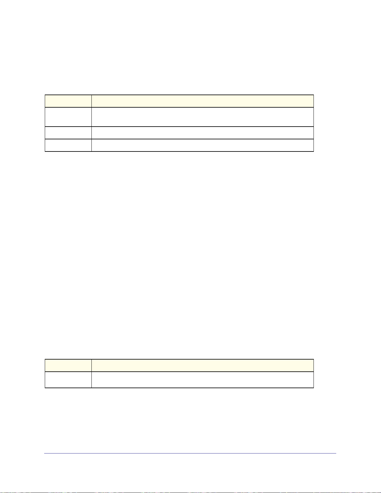
ProSafe Managed Switch
Format voice vlan {<id> | dot1p <priority> | none | untagged}
Mode
Interface Config
You can configure Voice VLAN in one of three different ways:
Parameter Description
dot1p
none
untagged
Configure the IP phone to use 802.1p priority tagging for voice traffic and to use the
default native VLAN (VLAN 0) to carry all traffic. Valid <priority> range is 0 to 7.
Allow the IP phone to use its own configuration to send untagged voice traffic.
Configure the phone to send untagged voice traffic.
no voice vlan (Interface Config)
Use this command to disable the Voice VLAN capability on the interface.
Format no voice vlan
Mode
Interface Config
voice vlan data priority
Use this command to either trust or untrust the data traffic arriving on the Voice VLAN port.
Default
Format voice vlan data priority {untrust | trust}
Mode
trust
Interface Config
show voice vlan
Format show voice vlan [interface {<unit/slot/port> | all}]
Mode
When the interface parameter is not specified, only the global mode of the Voice VLAN is
displayed.
Term Definition
Administrative
Mode
Privileged EXEC
The Global Voice VLAN mode.
Switching Commands
80
Page 81

ProSafe Managed Switch
When the interface is specified:
Term Definition
Voice VLAN Interface Mode
Voice VLAN ID
Voice VLAN Priority
Voice VLAN Untagged
Voice VLAN CoS Override
Voice VLAN Status
The admin mode of the Voice VLAN on the interface.
The Voice VLAN ID
The do1p priority for the Voice VLAN on the port.
The tagging option for the Voice VLAN traffic.
The Override option for the voice traffic arriving on the port.
The operational status of Voice VLAN on the port.
.
Provisioning (IEEE 802.1p) Commands
This section describes the commands you use to configure provisioning, which allows you to
prioritize ports.
vlan port priority all
This command configures the port priority assigned for untagged packets for all ports
presently plugged into the device. The range for the priority is 0-7. Any subsequent per port
configuration will override this configuration setting.
Format vlan port priority all <priority>
Mode
Global Config
vlan priority
This command configures the default 802.1p port priority assigned for untagged packets for a
specific interface. The range for the priority is 0–7.
Default
Format vlan priority <priority>
Mode
0
Interface Config
Protected Ports Commands
This section describes commands you use to configure and view protected ports on a switch.
Protected ports do not forward traffic to each other, even if they are on the same VLAN.
However, protected ports can forward traffic to all unprotected ports in their group.
Unprotected ports can forward traffic to both protected and unprotected ports. Ports are
unprotected by default.
Switching Commands
81
Page 82

ProSafe Managed Switch
If an interface is configured as a protected port, and you add that interface to a Port Channel
or Link Aggregation Group (LAG), the protected port status becomes operationally disabled
on the interface, and the interface follows the configuration of the LAG port. However, the
protected port configuration for the interface remains unchanged. Once the interface is no
longer a member of a LAG, the current configuration for that interface automatically becomes
effective.
switchport protected (Global Config)
Use this command to create a protected port group. The <groupid> parameter identifies the
set of protected ports. Use the name <name> pair to assign a name to the protected port
group. The name can be up to 32 alphanumeric characters long, including blanks. The
default is blank.
Note: Port protection occurs within a single switch. Protected port
configuration does not affect traffic between ports on two different
switches. No traffic forwarding is possible between two protected
ports.
Format switchport protected <groupid> name <name>
Mode
Global Config
no switchport protected (Global Config)
Use this command to remove a protected port group. The groupid parameter identifies the
set of protected ports. Use the name keyword to remove the name from the group.
Format NO switchport protected <groupid> name
Mode
Global Config
switchport protected (Interface Config)
Use this command to add an interface to a protected port group. The <groupid> parameter
identifies the set of protected ports to which this interface is assigned. You can only configure
an interface as protected in one group.
Note: Port protection occurs within a single switch. Protected port
configuration does not affect traffic between ports on two different
switches. No traffic forwarding is possible between two protected
ports.
Switching Commands
82
Page 83

ProSafe Managed Switch
Default
Format switchport protected <groupid>
Mode
unprotected
Interface Config
no switchport protected (Interface Config)
Use this command to configure a port as unprotected. The groupid parameter identifies the
set of protected ports to which this interface is assigned.
Format no switchport protected <groupid>
Mode
Interface Config
show switchport protected
This command displays the status of all the interfaces, including protected and unprotected
interfaces.
Format show switchport protected <groupid>
Mode
• Privileged EXEC
• User EXEC
Term Definition
Group ID
Name
List of Physical
Ports
The number that identifies the protected port group.
An optional name of the protected port group. The name can be up to 32 alphanumeric
characters long, including blanks. The default is blank.
List of ports, which are configured as protected for the group identified with <groupid>. If
no port is configured as protected for this group, this field is blank.
show interfaces switchport
This command displays the status of the interface (protected/unprotected) under the groupid.
Format show interfaces switchport <unit/slot/port> <groupid>
Mode
Term Definition
Name
Protected port
• Privileged EXEC
• User EXEC
A string associated with this group as a convenience. It can be up to 32 alphanumeric
characters long, including blanks. The default is blank. This field is optional.
Indicates whether the interface is protected or not. It shows TRUE or FALSE. If the group
is a multiple groups then it shows TRUE in Group <groupid>.
Switching Commands
83
Page 84

ProSafe Managed Switch
Private Group Commands
This section describes commands used to configure private group and view private group
configuration information.
Private group can be used to create a group of ports that can or can not share traffic to each
others in the same VLAN group. The main application is to isolate a group of users from
another without using VLAN.
switchport private-group
This command is used to assign one port or a range of ports to private group
<privategroup-name> (or <private-group-id>).
The ingress traffic from a port in private group can be forwarded to other ports either in the
same private group or anyone in the same VLAN that are not in a private group.
By default, a port does not belong to any private group. A port cannot be in more than one
private group. An error message should return when that occurred. To change a port’s private
group, first the port must be removed from its private group.
Default
Format
Mode
port not associated with any group.
switchport private-group [<privategroup-name>|<privategroup-id>]
Interface Config
no switchport private group
This command is used to remove the specified port from the given private group.
Format
Mode
no switchport private-group [<privategroup-name>|<privategroup-id>]
Interface Config
private-group name
This command is used to create a private group with name <private-group-name>. The name
string can be up to 24 bytes of non-blank characters. The total number of private groups is
192 such that the valid range for the ID is <1-192>.
The <private-group-id> field is optional. If not specified, a group id not used will be assigned
automatically.
The mode can be either “isolated” or “community”. When in “isolated” mode, the member port
in the group cannot forward its egress traffic to any other members in the same group. By
Switching Commands
84
Page 85

ProSafe Managed Switch
default, the mode is “community” mode that each member port can forward traffic to other
members in the same group, but not to members in other groups.
Format
Mode
private-group name <privategroup-name> [<groupid>] [mode {community|isolated}]
Global Config
no private-group name
This command is used to remove the specified private group.
Format
Mode
private-group name <privategroup-name>
Global Config
show private-group
This command displays the private groups’ information.
Format
Mode
Term Definition
Interface
Port VLANID
Private Group
ID
Private Group
Name
Private Group
show private-groupname [<private-group-name>|<private-group-id>|port <unit/slot/port>]
Privileged EXEC
Valid slot and port number separated by forward slashes.
The VLAN ID associated with the port.
Total number of private groups is 192.
The name string can be up to 24 bytes of non-blank characters
The mode can be either “isolated” or “community”.
GARP Commands
This section describes the commands you use to configure Generic Attribute Registration
Protocol (GARP) and view GARP status. The commands in this section affect both GARP
VLAN Registration Protocol (GVRP) and Garp Multicast Registration Protocol (GMRP).
GARP is a protocol that allows client stations to register with the switch for membership in
VLANS (by using GVMP) or multicast groups (by using GVMP).
set garp timer join
This command sets the GVRP join time for one port (Interface Config mode) or all (Global
Config mode) and per GARP. Join time is the interval between the transmission of GARP
Protocol Data Units (PDUs) registering (or re-registering) membership for a VLAN or
Switching Commands
85
Page 86

ProSafe Managed Switch
multicast group. This command has an effect only when GVRP is enabled. The time is from
10 to 100 (centiseconds). The value 20 centiseconds is 0.2 seconds.
Default
Format set garp timer join <10-100>
Mode
20
• Interface Config
• Global Config
no set garp timer join
This command sets the GVRP join time (for one or all ports and per GARP) to the default and
only has an effect when GVRP is enabled.
Format no set garp timer join
Mode
• Interface Config
• Global Config
set garp timer leave
This command sets the GVRP leave time for one port (Interface Config mode) or all ports
(Global Config mode) and only has an effect when GVRP is enabled. Leave time is the time
to wait after receiving an unregister request for a VLAN or a multicast group before deleting
the VLAN entry. This can be considered a buffer time for another station to assert registration
for the same attribute in order to maintain uninterrupted service. The leave time is 20 to 600
(centiseconds). The value 60 centiseconds is 0.6 seconds.
Default
Format set garp timer leave <20-600>
Mode
60
• Interface Config
• Global Config
no set garp timer leave
This command sets the GVRP leave time on all ports or a single port to the default and only
has an effect when GVRP is enabled.
Format no set garp timer leave
Mode
• Interface Config
• Global Config
set garp timer leaveall
This command sets how frequently Leave All PDUs are generated. A Leave All PDU
indicates that all registrations will be unregistered. Participants would need to rejoin in order
to maintain registration. The value applies per port and per GARP participation. The time may
Switching Commands
86
Page 87

ProSafe Managed Switch
range from 200 to 6000 (centiseconds). The value 1000 centiseconds is 10 seconds. You can
use this command on all ports (Global Config mode) or a single port (Interface Config mode),
and it only has an effect only when GVRP is enabled.
Default
Format set garp timer leaveall <200-6000>
Mode
1000
• Interface Config
• Global Config
no set garp timer leaveall
This command sets how frequently Leave All PDUs are generated the default and only has
an effect when GVRP is enabled.
Format no set garp timer leaveall
Mode
• Interface Config
• Global Config
show garp
This command displays GARP information.
Format show garp
Mode
• Privileged EXEC
• User EXEC
Term Definition
GMRP Admin Mode
GVRP Admin Mode
The administrative mode of GARP Multicast Registration Protocol (GMRP) for the
system.
The administrative mode of GARP VLAN Registration Protocol (GVRP) for the
system.
GVRP Commands
This section describes the commands you use to configure and view GARP VLAN
Registration Protocol (GVRP) information. GVRP-enabled switches exchange VLAN
configuration information, which allows GVRP to provide dynamic VLAN creation on trunk
ports and automatic VLAN pruning.
Note: If GVRP is disabled, the system does not forward GVRP messages.
Switching Commands
87
Page 88

ProSafe Managed Switch
set gvrp adminmode
This command enables GVRP on the system.
Default
Format set gvrp adminmode
Mode
disabled
Privileged EXEC
no set gvrp adminmode
This command disables GVRP.
Format no set gvrp adminmode
Mode
Privileged EXEC
set gvrp interfacemode
This command enables GVRP on a single port (Interface Config mode) or all ports (Global
Config mode).
Default
Format set gvrp interfacemode
Mode
disabled
• Interface Config
• Global Config
no set gvrp interfacemode
This command disables GVRP on a single port (Interface Config mode) or all ports (Global
Config mode). If GVRP is disabled, Join Time, Leave Time and Leave All Time have no
effect.
Format no set gvrp interfacemode
Mode
• Interface Config
• Global Config
show gvrp configuration
This command displays Generic Attributes Registration Protocol (GARP) information for one
or all interfaces.
Format show gvrp configuration {<unit/slot/port> | all}
Mode
• Privileged EXEC
• User EXEC
Switching Commands
88
Page 89

Term Definition
Interface
Join Timer
Leave Timer
LeaveAll Timer
Port GVMRP
Mode
Valid slot and port number separated by forward slashes.
The interval between the transmission of GARP PDUs registering (or re-registering)
membership for an attribute. Current attributes are a VLAN or multicast group. There is
an instance of this timer on a per-Port, per-GARP participant basis. Permissible values
are 10 to 100 centiseconds (0.1 to 1.0 seconds). The factory default is 20 centiseconds
(0.2 seconds). The finest granularity of specification is one centisecond (0.01 seconds).
The period of time to wait after receiving an unregister request for an attribute before
deleting the attribute. Current attributes are a VLAN or multicast group. This may be
considered a buffer time for another station to assert registration for the same attribute in
order to maintain uninterrupted service. There is an instance of this timer on a per-Port,
per-GARP participant basis. Permissible values are 20 to 600 centiseconds (0.2 to 6.0
seconds). The factory default is 60 centiseconds (0.6 seconds).
This Leave All Time controls how frequently LeaveAll PDUs are generated. A LeaveAll
PDU indicates that all registrations will shortly be deregistered. Participants will need to
rejoin in order to maintain registration. There is an instance of this timer on a per-Port,
per-GARP participant basis. The Leave All Period Timer is set to a random value in the
range of LeaveAllTime to 1.5*LeaveAllTime. Permissible values are 200 to 6000
centiseconds (2 to 60 seconds). The factory default is 1000 centiseconds (10 seconds).
The GVRP administrative mode for the port, which is enabled or disabled (default). If this
parameter is disabled, Join Time, Leave Time and Leave All Time have no effect.
ProSafe Managed Switch
GMRP Commands
This section describes the commands you use to configure and view GARP Multicast
Registration Protocol (GMRP) information. Like IGMP snooping, GMRP helps control the
flooding of multicast packets. GMRP-enabled switches dynamically register and de-register
group membership information with the MAC networking devices attached to the same
segment. GMRP also allows group membership information to propagate across all
networking devices in the bridged LAN that support Extended Filtering Services.
Note: If GMRP is disabled, the system does not forward GMRP
messages.
set gmrp adminmode
This command enables GARP Multicast Registration Protocol (GMRP) on the system.
Default
Format set gmrp adminmode
Mode
disabled
Privileged EXEC
Switching Commands
89
Page 90

ProSafe Managed Switch
no set gmrp adminmode
This command disables GARP Multicast Registration Protocol (GMRP) on the system.
Format no set gmrp adminmode
Mode
Privileged EXEC
set gmrp interfacemode
This command enables GARP Multicast Registration Protocol on a single interface (Interface
Config mode) or all interfaces (Global Config mode). If an interface which has GARP enabled
is enabled for routing or is enlisted as a member of a port-channel (LAG), GARP functionality
is disabled on that interface. GARP functionality is subsequently re-enabled if routing is
disabled and port-channel (LAG) membership is removed from an interface that has GARP
enabled.
Default
Format set gmrp interfacemode
Mode
disabled
• Interface Config
• Global Config
no set gmrp interfacemode
This command disables GARP Multicast Registration Protocol on a single interface or all
interfaces. If an interface which has GARP enabled is enabled for routing or is enlisted as a
member of a port-channel (LAG), GARP functionality is disabled. GARP functionality is
subsequently re-enabled if routing is disabled and port-channel (LAG) membership is
removed from an interface that has GARP enabled.
Format no set gmrp interfacemode
Mode
• Interface Config
• Global Config
show gmrp configuration
This command displays Generic Attributes Registration Protocol (GARP) information for one
or all interfaces.
Format show gmrp configuration {<unit/slot/port> | all}
Mode
• Privileged EXEC
• User EXEC
Switching Commands
90
Page 91

Term Definition
Interface
Join Timer
Leave Timer
LeaveAll Timer
Port GMRP
Mode
The unit/slot/port of the interface that this row in the table describes.
The interval between the transmission of GARP PDUs registering (or re-registering)
membership for an attribute. Current attributes are a VLAN or multicast group. There is
an instance of this timer on a per-port, per-GARP participant basis. Permissible values
are 10 to 100 centiseconds (0.1 to 1.0 seconds). The factory default is 20 centiseconds
(0.2 seconds). The finest granularity of specification is 1 centisecond (0.01 seconds).
The period of time to wait after receiving an unregister request for an attribute before
deleting the attribute. Current attributes are a VLAN or multicast group. This may be
considered a buffer time for another station to assert registration for the same attribute in
order to maintain uninterrupted service. There is an instance of this timer on a per-Port,
per-GARP participant basis. Permissible values are 20 to 600 centiseconds (0.2 to 6.0
seconds). The factory default is 60 centiseconds (0.6 seconds).
This Leave All Time controls how frequently LeaveAll PDUs are generated. A LeaveAll
PDU indicates that all registrations will shortly be deregistered. Participants will need to
rejoin in order to maintain registration. There is an instance of this timer on a per-Port,
per-GARP participant basis. The Leave All Period Timer is set to a random value in the
range of LeaveAllTime to 1.5*LeaveAllTime. Permissible values are 200 to 6000
centiseconds (2 to 60 seconds). The factory default is 1000 centiseconds (10 seconds).
The GMRP administrative mode for the port. It may be enabled or disabled. If this
parameter is disabled, Join Time, Leave Time and Leave All Time have no effect.
ProSafe Managed Switch
show mac-address-table gmrp
This command displays the GMRP entries in the Multicast Forwarding Database (MFDB)
table.
Format show mac-address-table gmrp
Mode
Term Definition
Mac Address
Type
Description
Interfaces
Privileged EXEC
A unicast MAC address for which the switch has forwarding and or filtering information.
The format is 6 or 8 two-digit hexadecimal numbers that are separated by colons, for
example 01:23:45:67:89:AB. In an IVL system the MAC address is displayed as 8 bytes.
The type of the entry. Static entries are those that are configured by the end user.
Dynamic entries are added to the table as a result of a learning process or protocol.
The text description of this multicast table entry.
The list of interfaces that are designated for forwarding (Fwd:) and filtering (Flt:).
Port-Based Network Access Control Commands
This section describes the commands you use to configure port-based network access
control (802.1x). Port-based network access control allows you to permit access to network
services only to and devices that are authorized and authenticated.
Switching Commands
91
Page 92

ProSafe Managed Switch
clear dot1x statistics
This command resets the 802.1x statistics for the specified port or for all ports.
Format clear dot1x statistics {<unit/slot/port> | all}
Mode
Privileged EXEC
clear radius statistics
This command is used to clear all RADIUS statistics.
Format clear radius statistics
Mode
Privileged EXEC
dot1x guest-vlan
This command configures VLAN as guest vlan on a per port basis. The command specifies
an active VLAN as an IEEE 802.1x guest VLAN. The range is 1 to the maximum VLAN ID
supported by the platform.
Default
Format dot1x guest-vlan <vlan-id>
Mode
disabled
Interface Config
no dot1x guest-vlan
This command disables Guest VLAN on the interface.
Default
Format no dot1x guest-vlan
Mode
disabled
Interface Config
dot1x initialize
This command begins the initialization sequence on the specified port. This command is only
valid if the control mode for the specified port is “auto” or “mac-based”. If the control mode is
not 'auto' or “mac-based”, an error will be returned.
Format dot1x initialize <unit/slot/port>
Mode
Privileged EXEC
dot1x mac-auth-bypass
This command enables MAC-Based Authentication Bypass (MAB) for 802.1x-unaware
clients. MAB provides 802.1x-unaware clients controlled access to the network using the
Switching Commands
92
Page 93

ProSafe Managed Switch
devices’ MAC address as an identifier. This requires that the known and allowable MAC
address and corresponding access rights be pre-populated in the authentication server. MAB
works only when the port control mode of the port is MAC-based.
Format dot1x mac-auth-bypass
Mode
Interface Config
no dot1x mac-auth-bypass
This command disables MAB for 802.1x-unaware clients.
Format no dot1x mac-auth-bypass
Mode
Interface Config
dot1x max-req
This command sets the maximum number of times the authenticator state machine on this
port will transmit an EAPOL EAP Request/Identity frame before timing out the supplicant.
The <count> value must be in the range 1 - 10.
Default
Format dot1x max-req
Mode
2
<count>
Interface Config
no dot1x max-req
This command sets the maximum number of times the authenticator state machine on this
port will transmit an EAPOL EAP Request/Identity frame before timing out the supplicant.
Format no dot1x max-req
Mode
Interface Config
dot1x max-users
Use this command to set the maximum number of clients supported on the port when
MAC-based dot1x authentication is enabled on the port. The maximum users supported per
port is dependent on the product. The <count> value is in the range 1 - 16.
Default
Format dot1x max-users
Mode
16
<count>
Interface Config
Switching Commands
93
Page 94

ProSafe Managed Switch
no dot1x max-users
This command resets the maximum number of clients allowed per port to its default value.
Format no dot1x max-req
Mode
Interface Config
dot1x port-control
This command sets the authentication mode to use on the specified port. Select
force-unauthorized to specify that the authenticator PAE unconditionally sets the
controlled port to unauthorized. Select force-authorized to specify that the authenticator
PAE unconditionally sets the controlled port to authorized. Select auto to specify that the
authenticator PAE sets the controlled port mode to reflect the outcome of the authentication
exchanges between the supplicant, authenticator and the authentication server. If the
mac-based option is specified, then MAC-based dot1x authentication is enabled on the port.
Default
Format dot1x port-control {force-unauthorized | force-authorized | auto |
Mode
auto
mac-based}
Interface Config
no dot1x port-control
This command sets the 802.1x port control mode on the specified port to the default value.
Format no dot1x port-control
Mode
Interface Config
dot1x port-control all
This command sets the authentication mode to use on all ports. Select
force-unauthorized to specify that the authenticator PAE unconditionally sets the
controlled port to unauthorized. Select force-authorized to specify that the authenticator
PAE unconditionally sets the controlled port to authorized. Select auto to specify that the
authenticator PAE sets the controlled port mode to reflect the outcome of the authentication
exchanges between the supplicant, authenticator and the authentication server. If the
mac-based option is specified, then MAC-based dot1x authentication is enabled on the port.
Default
Format dot1x port-control all {force-unauthorized | force-authorized | auto
Mode
auto
| mac-based}
Global Config
Switching Commands
94
Page 95

ProSafe Managed Switch
no dot1x port-control all
This command sets the authentication mode on all ports to the default value.
Format no dot1x port-control all
Mode
Global Config
dot1x re-authenticate
This command begins the re-authentication sequence on the specified port. This command is
only valid if the control mode for the specified port is “auto” or “mac-based”. If the control
mode is not “auto” or “mac-based”, an error will be returned.
Format dot1x re-authenticate <unit/slot/port>
Mode
Privileged EXEC
dot1x re-authentication
This command enables re-authentication of the supplicant for the specified port.
Default
Format dot1x re-authentication
Mode
disabled
Interface Config
no dot1x re-authentication
This command disables re-authentication of the supplicant for the specified port.
Format no dot1x re-authentication
Mode
Interface Config
dot1x system-auth-control
Use this command to enable the dot1x authentication support on the switch. While disabled,
the dot1x configuration is retained and can be changed, but is not activated.
Default
Format dot1x system-auth-control
Mode
disabled
Global Config
Switching Commands
95
Page 96

ProSafe Managed Switch
no dot1x system-auth-control
This command is used to disable the dot1x authentication support on the switch.
Format no dot1x system-auth-control
Mode
Global Config
dot1x timeout
This command sets the value, in seconds, of the timer used by the authenticator state
machine on this port. Depending on the token used and the value (in seconds) passed,
various timeout configurable parameters are set. The following tokens are supported:
Tokens Definition
guest-vlan-period
reauth-period
quiet-period
tx-period
supp-timeout
server-timeout
The time, in seconds, for which the authenticator waits to see if any EAPOL packets are
received on a port before authorizing the port and placing the port in the guest vlan (if
configured). The guest vlan timer is only relevant when guest vlan has been configured
on that specific port.
The value, in seconds, of the timer used by the authenticator state machine on this port
to determine when re-authentication of the supplicant takes place. The reauth-period
must be a value in the range 1 - 65535.
The value, in seconds, of the timer used by the authenticator state machine on this port
to define periods of time in which it will not attempt to acquire a supplicant. The
quiet-period must be a value in the range 0 - 65535.
The value, in seconds, of the timer used by the authenticator state machine on this port
to determine when to send an EAPOL EAP Request/Identity frame to the supplicant. The
quiet-period must be a value in the range 1 - 65535.
The value, in seconds, of the timer used by the authenticator state machine on this port
to timeout the supplicant. The supp-timeout must be a value in the range 1 - 65535.
The value, in seconds, of the timer used by the authenticator state machine on this port
to timeout the authentication server. The supp-timeout must be a value in the range 1 -
65535.
Default
Format dot1x timeout {{guest-vlan-period <seconds>} |{reauth-period
Mode
• guest-vlan-period: 90 seconds
• reauth-period: 3600 seconds
• quiet-period: 60 seconds
• tx-period: 30 seconds
• supp-timeout: 30 seconds
• server-timeout: 30 seconds
<seconds>} | {quiet-period <seconds>} | {tx-period <seconds>} |
{supp-timeout <seconds>} | {server-timeout <seconds>}}
Interface Config
Switching Commands
96
Page 97

ProSafe Managed Switch
no dot1x timeout
This command sets the value, in seconds, of the timer used by the authenticator state
machine on this port to the default values. Depending on the token used, the corresponding
default values are set.
Format no dot1x timeout {guest-vlan-period | reauth-period | quiet-period |
tx-period | supp-timeout | server-timeout}
Mode
Interface Config
dot1x unauthenticated-vlan
Use this command to configure the unauthenticated VLAN associated with that port. The
unauthenticated VLAN ID can be a valid VLAN ID from 0-Maximum supported VLAN ID
(4093 for 7000 series). The unauthenticated VLAN must be statically configured in the VLAN
database to be operational. By default, the unauthenticated VLAN is 0, i.e. invalid and not
operational.
Default
Format dot1x unauthenticated-vlan <vlan id>
Mode
0
Interface Config
no dot1x unauthenticated-vlan
This command resets the unauthenticated-vlan associated with the port to its default value.
Format no dot1x unauthenticated-vlan
Mode
Interface Config
dot1x user
This command adds the specified user to the list of users with access to the specified port or
all ports. The <user> parameter must be a configured user.
Format dot1x user <user> {<unit/slot/port> | all}
Mode
no dot1x user
Global Config
This command removes the user from the list of users with access to the specified port or all
ports.
Format no dot1x user <user> {<unit/slot/port> | all}
Mode
Global Config
Switching Commands
97
Page 98

ProSafe Managed Switch
clear dot1x authentication-history
This command clears the authentication history table captured during successful and
unsuccessful authentication on all interface or the specified interface.
Format clear dot1x authentication-history [unit/slot/port]
Mode
Global Config
dot1x dynamic-vlan enable
Use this command to enable the switch to create VLANs dynamically when a RADIUS
assigned VLAN does not exist in the switch.
Format dot1x dynamic-vlan enable
Mode
Default
Global Config
Disabled
no dot1x dynamic-vlan enable
Use this command to disable the switch from creating VLANs dynamically when a RADIUS
assigned VLAN does not exist in the switch.
Format no dot1x dynamic-vlan enable
Mode
Global Config
dot1x system-auth-control monitor
Use this command to enable the 802.1X monitor mode on the switch. The purpose of Monitor
mode is to help troubleshoot port-based authentication configuration issues without
disrupting network access for hosts connected to the switch. In Monitor mode, a host is
granted network access to an 802.1X-enabled port even if it fails the authentication process.
The results of the process are logged for diagnostic purposes.
Format dot1x system-auth-control monitor
Mode
Default
no dot1x system-auth-control monitor
Global Config
Disabled
Use this command to disable the 802.1X monitor on the switch.
Format no dot1x system-auth-control monitor
Mode
Global Config
Switching Commands
98
Page 99

ProSafe Managed Switch
show dot1x authentication-history
This command displays 802.1X authentication events and information during successful and
unsuccessful Dot1x authentication process for all interfaces or the specified interface. Use
the optional keywords to display only failure authentication events in summary or in detail.
Format show dot1x authentication-history {unit/slot/port | all}
[failedauth-only] [detail]
Mode
Term Definition
Time Stamp
Interface
Mac-Address
VLAN assigned
VLAN assigned
Reason
Auth Status
Reason
Privileged EXEC
The exact time at which the event occurs.
Physical Port on which the event occurs.
The supplicant/client MAC address.
The VLAN assigned to the client/port on authentication.
The type of VLAN ID assigned, which can be Guest VLAN, Unauth, Default, RADIUS
Assigned, or Monitor Mode VLAN ID.
The authentication status.
The actual reason behind the successful or failed authentication.
show authentication methods
This command displays information about the authentication methods.
Format show authentication methods
Mode
The following is an example of this command:
Login Authentication Method Lists
________________________________
Console_Default: None
Network_Default:Local
Enable Authentication Lists
_____________________
Console_Default: Enable None
Network_Default:Enable
Line Login Method List Enable Method Lists
_____________________
Console Console_Default Console_Default
Telnet Network_Default Network_Default
SSH Network_Default Network_Default
http : Local
https : Local
dot1x :
Privileged EXEC
Switching Commands
99
Page 100

ProSafe Managed Switch
show dot1x
This command is used to show a summary of the global dot1x configuration, summary
information of the dot1x configuration for a specified port or all ports, the detailed dot1x
configuration for a specified port and the dot1x statistics for a specified port - depending on
the tokens used.
Format show dot1x [{summary {<unit/slot/port> | all} | detail
<unit/slot/port> | statistics <unit/slot/port>]
Mode
If you do not use the optional parameters <unit/slot/port> or <vlanid>, the command
displays the global dot1x mode, the VLAN Assignment mode, and the Dynamic VLAN
Creation mode.
Term Definition
Administrative
Mode
VLAN
Assignment
Mode
Dynamic VLAN
Creation Mode
Monitor Mode
Privileged EXEC
Indicates whether authentication control on the switch is enabled or disabled.
Indicates whether assignment of an authorized port to a RADIUS assigned VLAN is
allowed (enabled) or not (disabled).
Indicates whether the switch can dynamically create a RADIUS-assigned VLAN if it does
not currently exist on the switch.
Indicates whether the Dot1x Monitor mode on the switch is enabled or disabled.
If you use the optional parameter summary {<unit/slot/port> | all}, the dot1x
configuration for the specified port or all ports are displayed.
Term Definition
Interface
Control Mode
Operating
Control Mode
Reauthenticatio
n Enabled
Port Status
The interface whose configuration is displayed.
The configured control mode for this port. Possible values are force-unauthorized |
force-authorized | auto | mac-based | authorized | unauthorized.
The control mode under which this port is operating. Possible values are authorized |
unauthorized.
Indicates whether re-authentication is enabled on this port.
Indicates whether the port is authorized or unauthorized. Possible values are authorized
| unauthorized.
Switching Commands
100
 Loading...