

Page 1

M4200 and M4300 Series ProSAFE Managed Switches
Software Administration Manual
Software Version 12.0.2
July 2016
202-11586-03
350 East Plumeria Drive
San Jose, CA 95134
USA
Page 2

Managed Switches
Support
Thank you for purchasing this NETGEAR product. You can visit www.netgear.com/support to register your product, get help,
access the latest downloads and user manuals, and join our community. We recommend that you use only official NETGEAR
support resources.
Conformity
For the current EU Declaration of Conformity, visit http://kb.netgear.com/app/answers/detail/a_id/11621.
Compliance
For regulatory compliance information, visit http://www.netgear.com/about/regulatory.
See the regulatory compliance document before connecting the power supply.
Trademarks
© NETGEAR, Inc., NETGEAR and the NETGEAR Logo are trademarks of NETGEAR, Inc. Any non-NETGEAR trademarks are
used for reference purposes only.
Revision History
Publication
Part Number
202-11586-03 July 2016 Added or changed the following sections:
202-11586-02 May 2016 Updated Compatible Switch Models.
202-11586-01 December 2015 Initial publication.
Publication
Date
Comments
• Add ACL Remarks
• Change the Sequence of an ACL Rule
• Command Authorization
• Privileged Exec Command Mode Authorization
• Error Disablement and Automatic Error Recovery
• Loop Protection
• Nondisruptive Configuration Management
• DHCP L3 Relay
Made minor changes to other sections.
2
Page 3

Table of Contents
Chapter 1 Documentation Resources
Chapter 2 VLANs
VLAN Concepts . . . . . . . . . . . . . . . . . . . . . . . . . . . . . . . . . . . . . . . . . . . . . . . . . . . . . 19
Create Two VLANs. . . . . . . . . . . . . . . . . . . . . . . . . . . . . . . . . . . . . . . . . . . . . . . . . . . 20
CLI: Create Two VLANs . . . . . . . . . . . . . . . . . . . . . . . . . . . . . . . . . . . . . . . . . . . . 20
Web Interface: Create Two VLANs . . . . . . . . . . . . . . . . . . . . . . . . . . . . . . . . . . . 20
Assign Ports to VLAN 2 . . . . . . . . . . . . . . . . . . . . . . . . . . . . . . . . . . . . . . . . . . . . . . 21
CLI: Assign Ports to VLAN 2 . . . . . . . . . . . . . . . . . . . . . . . . . . . . . . . . . . . . . . . . 21
Web Interface: Assign Ports to VLAN 2. . . . . . . . . . . . . . . . . . . . . . . . . . . . . . . 22
Create Three VLANs . . . . . . . . . . . . . . . . . . . . . . . . . . . . . . . . . . . . . . . . . . . . . . . . . 23
CLI: Create Three VLANs . . . . . . . . . . . . . . . . . . . . . . . . . . . . . . . . . . . . . . . . . . . 23
Web Interface: Create Three VLANs . . . . . . . . . . . . . . . . . . . . . . . . . . . . . . . . . 23
Assign Ports to VLAN 3 . . . . . . . . . . . . . . . . . . . . . . . . . . . . . . . . . . . . . . . . . . . . . . 25
CLI: Assign Ports to VLAN 3 . . . . . . . . . . . . . . . . . . . . . . . . . . . . . . . . . . . . . . . . 25
Web Interface: Assign Ports to VLAN 3. . . . . . . . . . . . . . . . . . . . . . . . . . . . . . . 25
Assign VLAN 3 as the Default VLAN for Port 1/0/2 . . . . . . . . . . . . . . . . . . . . . . 26
CLI: Assign VLAN 3 as the Default VLAN for Port 1/0/2 . . . . . . . . . . . . . . . . 26
Web Interface: Assign VLAN 3 as the Default VLAN for Port 1/0/2 . . . . . . 27
Create a MAC-Based VLAN . . . . . . . . . . . . . . . . . . . . . . . . . . . . . . . . . . . . . . . . . . . 27
CLI: Create a MAC-Based VLAN . . . . . . . . . . . . . . . . . . . . . . . . . . . . . . . . . . . . . 28
Web Interface: Assign a MAC-Based VLAN . . . . . . . . . . . . . . . . . . . . . . . . . . . 29
Create a Protocol-Based VLAN . . . . . . . . . . . . . . . . . . . . . . . . . . . . . . . . . . . . . . . . 31
CLI: Create a Protocol-Based VLAN . . . . . . . . . . . . . . . . . . . . . . . . . . . . . . . . . . 31
Web Interface: Create a Protocol-Based VLAN . . . . . . . . . . . . . . . . . . . . . . . . 32
Virtual VLANs: Create an IP Subnet–Based VLAN . . . . . . . . . . . . . . . . . . . . . . . . 35
CLI: Create an IP Subnet–Based VLAN . . . . . . . . . . . . . . . . . . . . . . . . . . . . . . . 36
Web Interface: Create an IP Subnet–Based VLAN. . . . . . . . . . . . . . . . . . . . . . 37
Voice VLANs . . . . . . . . . . . . . . . . . . . . . . . . . . . . . . . . . . . . . . . . . . . . . . . . . . . . . . . . 38
CLI: Configure Voice VLAN and Prioritize Voice Traffic. . . . . . . . . . . . . . . . . . 39
Web Interface: Configure Voice VLAN and Prioritize Voice Traffic . . . . . . . . 41
Configure GARP VLAN Registration Protocol . . . . . . . . . . . . . . . . . . . . . . . . . . . . 46
CLI: Enable GVRP. . . . . . . . . . . . . . . . . . . . . . . . . . . . . . . . . . . . . . . . . . . . . . . . . . 47
Web Interface: Configure GVRP on switch A . . . . . . . . . . . . . . . . . . . . . . . . . . 49
Web Interface: Configure GVRP on Switch B . . . . . . . . . . . . . . . . . . . . . . . . . . 51
Private VLANs . . . . . . . . . . . . . . . . . . . . . . . . . . . . . . . . . . . . . . . . . . . . . . . . . . . . . . 52
Assign Private-VLAN Types (Primary, Isolated, Community). . . . . . . . . . . . . . . 54
CLI: Assign Private-VLAN Type (Primary, Isolated, Community) . . . . . . . . . 54
Web Interface: Assign Private-VLAN Type (Primary,
Isolated, Community). . . . . . . . . . . . . . . . . . . . . . . . . . . . . . . . . . . . . . . . . . . . . . 54
3
Page 4

Managed Switches
Configure Private-VLAN Association . . . . . . . . . . . . . . . . . . . . . . . . . . . . . . . . . . . 56
CLI: Configure Private-VLAN Association. . . . . . . . . . . . . . . . . . . . . . . . . . . . . 56
Web Interface: Configure Private-VLAN Association . . . . . . . . . . . . . . . . . . . 56
Configure Private-VLAN Port Mode (Promiscuous, Host) . . . . . . . . . . . . . . . . . 57
CLI: Configure Private-VLAN Port Mode (Promiscuous, Host) . . . . . . . . . . . 57
Web Interface: Configure Private-VLAN Port Mode
(Promiscuous, Host). . . . . . . . . . . . . . . . . . . . . . . . . . . . . . . . . . . . . . . . . . . . . . . 57
Configure Private-VLAN Host Ports. . . . . . . . . . . . . . . . . . . . . . . . . . . . . . . . . . . . 58
CLI: Configure Private-VLAN Host Ports . . . . . . . . . . . . . . . . . . . . . . . . . . . . . 58
Web Interface: Assign Private-VLAN Port Host Ports. . . . . . . . . . . . . . . . . . . 59
Map Private-VLAN Promiscuous Port . . . . . . . . . . . . . . . . . . . . . . . . . . . . . . . . . . 60
CLI: Map Private-VLAN Promiscuous Port . . . . . . . . . . . . . . . . . . . . . . . . . . . . 60
Web Interface: Map Private-VLAN Promiscuous Port. . . . . . . . . . . . . . . . . . . 60
VLAN Access Ports and Trunk Ports . . . . . . . . . . . . . . . . . . . . . . . . . . . . . . . . . . . . 61
CLI: Configure a VLAN Trunk. . . . . . . . . . . . . . . . . . . . . . . . . . . . . . . . . . . . . . . . 62
Web Interface: Configure a VLAN Trunk . . . . . . . . . . . . . . . . . . . . . . . . . . . . . . 63
Chapter 3 LAGs
Link Aggregation Concepts . . . . . . . . . . . . . . . . . . . . . . . . . . . . . . . . . . . . . . . . . . . 68
Add Ports to LAGs. . . . . . . . . . . . . . . . . . . . . . . . . . . . . . . . . . . . . . . . . . . . . . . . . . . 69
CLI: Add Ports to the LAGs . . . . . . . . . . . . . . . . . . . . . . . . . . . . . . . . . . . . . . . . . 69
Web Interface: Add Ports to LAGs . . . . . . . . . . . . . . . . . . . . . . . . . . . . . . . . . . . 69
Chapter 4 Port Routing
Port Routing Concepts . . . . . . . . . . . . . . . . . . . . . . . . . . . . . . . . . . . . . . . . . . . . . . . 72
Port Routing Configuration . . . . . . . . . . . . . . . . . . . . . . . . . . . . . . . . . . . . . . . . . . . 72
Enable Routing for the Switch . . . . . . . . . . . . . . . . . . . . . . . . . . . . . . . . . . . . . . . . . 73
CLI: Enable Routing for the Switch . . . . . . . . . . . . . . . . . . . . . . . . . . . . . . . . . . . 73
Web Interface: Enable Routing for the Switch . . . . . . . . . . . . . . . . . . . . . . . . . 74
Enable Routing for Ports on the Switch . . . . . . . . . . . . . . . . . . . . . . . . . . . . . . . . . 74
CLI: Enable Routing for Ports on the Switch . . . . . . . . . . . . . . . . . . . . . . . . . . . 75
Web Interface: Enable Routing for Ports on the Switch . . . . . . . . . . . . . . . . . 75
Add a Default Route . . . . . . . . . . . . . . . . . . . . . . . . . . . . . . . . . . . . . . . . . . . . . . . . . 77
CLI: Add a Default Route . . . . . . . . . . . . . . . . . . . . . . . . . . . . . . . . . . . . . . . . . . . 77
Web Interface: Add a Default Route . . . . . . . . . . . . . . . . . . . . . . . . . . . . . . . . . 78
Add a Static Route . . . . . . . . . . . . . . . . . . . . . . . . . . . . . . . . . . . . . . . . . . . . . . . . . . . 78
CLI: Add a Static Route. . . . . . . . . . . . . . . . . . . . . . . . . . . . . . . . . . . . . . . . . . . . . 79
Web Interface: Add a Static Route . . . . . . . . . . . . . . . . . . . . . . . . . . . . . . . . . . . 79
Chapter 5 VLAN Routing
VLAN Routing Concepts . . . . . . . . . . . . . . . . . . . . . . . . . . . . . . . . . . . . . . . . . . . . . . 81
Create Two VLANs. . . . . . . . . . . . . . . . . . . . . . . . . . . . . . . . . . . . . . . . . . . . . . . . . . . 81
CLI: Create Two VLANs . . . . . . . . . . . . . . . . . . . . . . . . . . . . . . . . . . . . . . . . . . . . 82
Web Interface: Create Two VLANs . . . . . . . . . . . . . . . . . . . . . . . . . . . . . . . . . . . 83
Set Up VLAN Routing for the VLANs and the Switch. . . . . . . . . . . . . . . . . . . . . . 86
CLI: Set Up VLAN Routing for the VLANs and the Switch. . . . . . . . . . . . . . . . 86
4
Page 5

Managed Switches
Web Interface: Set Up VLAN Routing for the VLANs and the Switch . . . . . . 87
Chapter 6 RIP
Routing Information Protocol Concepts. . . . . . . . . . . . . . . . . . . . . . . . . . . . . . . . . 89
Enable Routing for the Switch . . . . . . . . . . . . . . . . . . . . . . . . . . . . . . . . . . . . . . . . . 90
CLI: Enable Routing for the Switch . . . . . . . . . . . . . . . . . . . . . . . . . . . . . . . . . . . 90
Web Interface: Enable Routing for the Switch . . . . . . . . . . . . . . . . . . . . . . . . . 90
Enable Routing for Ports. . . . . . . . . . . . . . . . . . . . . . . . . . . . . . . . . . . . . . . . . . . . . . 91
CLI: Enable Routing and Assigning IP Addresses for Ports
1/0/2 and 1/0/3 . . . . . . . . . . . . . . . . . . . . . . . . . . . . . . . . . . . . . . . . . . . . . . . . . 91
Web Interface: Enable Routing for the Ports . . . . . . . . . . . . . . . . . . . . . . . . . . 91
Enable RIP on the Switch . . . . . . . . . . . . . . . . . . . . . . . . . . . . . . . . . . . . . . . . . . . . . 93
CLI: Enable RIP on the Switch . . . . . . . . . . . . . . . . . . . . . . . . . . . . . . . . . . . . . . . 93
Web Interface: Enable RIP on the Switch. . . . . . . . . . . . . . . . . . . . . . . . . . . . . . 93
Enable RIP for Ports 1/0/2 and 1/0/3 . . . . . . . . . . . . . . . . . . . . . . . . . . . . . . . . . 94
CLI: Enable RIP for Ports 1/0/2 and 1/0/3 . . . . . . . . . . . . . . . . . . . . . . . . . . . 94
Web Interface: Enable RIP for Ports 1/0/2 and 1/0/3 . . . . . . . . . . . . . . . . . 94
Configure VLAN Routing with RIP Support . . . . . . . . . . . . . . . . . . . . . . . . . . . . . . 95
CLI: Configure VLAN Routing with RIP Support . . . . . . . . . . . . . . . . . . . . . . . . 95
Web Interface: Configure VLAN Routing with RIP Support . . . . . . . . . . . . . . 97
Chapter 7 OSPF
Open Shortest Path First Concepts. . . . . . . . . . . . . . . . . . . . . . . . . . . . . . . . . . . . 101
Inter-area Router. . . . . . . . . . . . . . . . . . . . . . . . . . . . . . . . . . . . . . . . . . . . . . . . . . . 101
CLI: Configure an Inter-area Router. . . . . . . . . . . . . . . . . . . . . . . . . . . . . . . . . 102
Web Interface: Configure an Inter-area Router . . . . . . . . . . . . . . . . . . . . . . .104
OSPF on a Border Router . . . . . . . . . . . . . . . . . . . . . . . . . . . . . . . . . . . . . . . . . . . . 108
CLI: Configure OSPF on a Border Router. . . . . . . . . . . . . . . . . . . . . . . . . . . . . 108
Web Interface: Configure OSPF on a Border Router . . . . . . . . . . . . . . . . . . . 109
Stub Areas. . . . . . . . . . . . . . . . . . . . . . . . . . . . . . . . . . . . . . . . . . . . . . . . . . . . . . . . . 114
CLI: Configure Area 1 as a Stub Area on A1 . . . . . . . . . . . . . . . . . . . . . . . . . . 114
Web Interface: Configure Area 1 as a Stub Area on A1 . . . . . . . . . . . . . . . .116
CLI: Configure Area 1 as a Stub Area on A2 . . . . . . . . . . . . . . . . . . . . . . . . . . 120
Web Interface: Configure Area 1 as a Stub Area on A2 . . . . . . . . . . . . . . . .121
NSSA Areas. . . . . . . . . . . . . . . . . . . . . . . . . . . . . . . . . . . . . . . . . . . . . . . . . . . . . . . . 123
CLI: Configure Area 1 as an NSSA Area . . . . . . . . . . . . . . . . . . . . . . . . . . . . . . 123
Web Interface: Configure Area 1 as an NSSA Area on A1. . . . . . . . . . . . . . . 125
CLI: Configure Area 1 as an NSSA Area on A2 . . . . . . . . . . . . . . . . . . . . . . . . 128
Web Interface: Configure Area 1 as an NSSA Area on A2. . . . . . . . . . . . . . . 130
VLAN Routing OSPF . . . . . . . . . . . . . . . . . . . . . . . . . . . . . . . . . . . . . . . . . . . . . . . . 134
CLI: Configure VLAN Routing OSPF . . . . . . . . . . . . . . . . . . . . . . . . . . . . . . . . . 135
Web Interface: Configure VLAN Routing OSPF . . . . . . . . . . . . . . . . . . . . . . .137
OSPFv3 . . . . . . . . . . . . . . . . . . . . . . . . . . . . . . . . . . . . . . . . . . . . . . . . . . . . . . . . . . .139
CLI: Configure OSPFv3. . . . . . . . . . . . . . . . . . . . . . . . . . . . . . . . . . . . . . . . . . . . 140
Web Interface: Configure OSPFv3 . . . . . . . . . . . . . . . . . . . . . . . . . . . . . . . . . . 142
5
Page 6

Managed Switches
Chapter 8 PBR
Policy-Based Routing Concepts . . . . . . . . . . . . . . . . . . . . . . . . . . . . . . . . . . . . . . 146
Route-Map Statements . . . . . . . . . . . . . . . . . . . . . . . . . . . . . . . . . . . . . . . . . . . . . 146
PBR Processing Logic . . . . . . . . . . . . . . . . . . . . . . . . . . . . . . . . . . . . . . . . . . . . . . . 147
PBR Configurations . . . . . . . . . . . . . . . . . . . . . . . . . . . . . . . . . . . . . . . . . . . . . . . . . 148
PBR Example . . . . . . . . . . . . . . . . . . . . . . . . . . . . . . . . . . . . . . . . . . . . . . . . . . . . . . 149
Chapter 9 ARP
Proxy ARP Concepts . . . . . . . . . . . . . . . . . . . . . . . . . . . . . . . . . . . . . . . . . . . . . . . . 153
Proxy ARP Examples . . . . . . . . . . . . . . . . . . . . . . . . . . . . . . . . . . . . . . . . . . . . . . . . 153
CLI: show ip interface. . . . . . . . . . . . . . . . . . . . . . . . . . . . . . . . . . . . . . . . . . . . . 153
CLI: ip proxy-arp. . . . . . . . . . . . . . . . . . . . . . . . . . . . . . . . . . . . . . . . . . . . . . . . . 153
Web Interface: Configure Proxy ARP on a Port . . . . . . . . . . . . . . . . . . . . . . . 154
Chapter 10 VRRP
Virtual Router Redundancy Protocol Concepts. . . . . . . . . . . . . . . . . . . . . . . . . . 156
VRRP on a Master Router . . . . . . . . . . . . . . . . . . . . . . . . . . . . . . . . . . . . . . . . . . . . 157
CLI: Configure VRRP on a Master Router . . . . . . . . . . . . . . . . . . . . . . . . . . . . 157
Web Interface: Configure VRRP on a Master Router. . . . . . . . . . . . . . . . . . . 158
VRRP on a Backup Router. . . . . . . . . . . . . . . . . . . . . . . . . . . . . . . . . . . . . . . . . . . . 159
CLI: Configure VRRP on a Backup Router . . . . . . . . . . . . . . . . . . . . . . . . . . . . 159
Web Interface: Configure VRRP on a Backup Router. . . . . . . . . . . . . . . . . . . 160
Chapter 11 ACLs
Access Control List Concepts. . . . . . . . . . . . . . . . . . . . . . . . . . . . . . . . . . . . . . . . . 163
MAC ACLs . . . . . . . . . . . . . . . . . . . . . . . . . . . . . . . . . . . . . . . . . . . . . . . . . . . . . . 163
IP ACLs . . . . . . . . . . . . . . . . . . . . . . . . . . . . . . . . . . . . . . . . . . . . . . . . . . . . . . . . . 164
ACL Configuration . . . . . . . . . . . . . . . . . . . . . . . . . . . . . . . . . . . . . . . . . . . . . . . 164
Set Up an IP ACL with Two Rules. . . . . . . . . . . . . . . . . . . . . . . . . . . . . . . . . . . . . . 164
CLI: Set Up an IP ACL with Two Rules . . . . . . . . . . . . . . . . . . . . . . . . . . . . . . . 165
Web Interface: Set Up an IP ACL with Two Rules . . . . . . . . . . . . . . . . . . . . . . 166
One-Way Access Using a TCP Flag in an ACL . . . . . . . . . . . . . . . . . . . . . . . . . . . 169
CLI: Configure One-Way Access Using a TCP Flag in an ACL . . . . . . . . . . . . 169
Web Interface: Configure One-Way Access Using a TCP
Flag in an ACL . . . . . . . . . . . . . . . . . . . . . . . . . . . . . . . . . . . . . . . . . . . . . . . . . . . 173
Use ACLs to Configure Isolated VLANs on a Layer 3 Switch. . . . . . . . . . . . . . . 184
CLI: Configure One-Way Access Using a TCP Flag in ACL
Commands . . . . . . . . . . . . . . . . . . . . . . . . . . . . . . . . . . . . . . . . . . . . . . . . . . . . . . 185
Web Interface: Configure One-Way Access Using a TCP
Flag in an ACL . . . . . . . . . . . . . . . . . . . . . . . . . . . . . . . . . . . . . . . . . . . . . . . . . . . 187
Set up a MAC ACL with Two Rules . . . . . . . . . . . . . . . . . . . . . . . . . . . . . . . . . . . . 195
CLI: Set up a MAC ACL with Two Rules . . . . . . . . . . . . . . . . . . . . . . . . . . . . . . 195
Web Interface: Set up a MAC ACL with Two Rules . . . . . . . . . . . . . . . . . . . . 196
Configure ACL Mirroring . . . . . . . . . . . . . . . . . . . . . . . . . . . . . . . . . . . . . . . . . . . . 198
CLI: Configure ACL Mirroring . . . . . . . . . . . . . . . . . . . . . . . . . . . . . . . . . . . . . . 199
6
Page 7

Managed Switches
Web Interface: Configure ACL Mirroring. . . . . . . . . . . . . . . . . . . . . . . . . . . . . 201
Configure ACL Redirection. . . . . . . . . . . . . . . . . . . . . . . . . . . . . . . . . . . . . . . . . . . 204
CLI: Redirect a Traffic Stream . . . . . . . . . . . . . . . . . . . . . . . . . . . . . . . . . . . . . . 205
Web Interface: Redirect a Traffic Stream . . . . . . . . . . . . . . . . . . . . . . . . . . . .206
Add ACL Remarks . . . . . . . . . . . . . . . . . . . . . . . . . . . . . . . . . . . . . . . . . . . . . . . . . . 209
Change the Sequence of an ACL Rule. . . . . . . . . . . . . . . . . . . . . . . . . . . . . . . . . . 210
Configure a Management ACL. . . . . . . . . . . . . . . . . . . . . . . . . . . . . . . . . . . . . . . . 212
Example 1: Permit Any Host to Access the Switch Through
Telnet or HTTP: . . . . . . . . . . . . . . . . . . . . . . . . . . . . . . . . . . . . . . . . . . . . . . . . . . 213
Example 2: Permit a Specific Host to Access the Switch
Through SSH Only. . . . . . . . . . . . . . . . . . . . . . . . . . . . . . . . . . . . . . . . . . . . . . . . 213
Configure IPv6 ACLs. . . . . . . . . . . . . . . . . . . . . . . . . . . . . . . . . . . . . . . . . . . . . . . . 213
CLI: Configure an IPv6 ACL . . . . . . . . . . . . . . . . . . . . . . . . . . . . . . . . . . . . . . . . 215
Web Interface: Configure an IPv6 ACL . . . . . . . . . . . . . . . . . . . . . . . . . . . . . . 216
Chapter 12 CoS Queuing
CoS Queuing Concepts. . . . . . . . . . . . . . . . . . . . . . . . . . . . . . . . . . . . . . . . . . . . . . 223
CoS Queue Mapping . . . . . . . . . . . . . . . . . . . . . . . . . . . . . . . . . . . . . . . . . . . . . . . . 223
Trusted Ports . . . . . . . . . . . . . . . . . . . . . . . . . . . . . . . . . . . . . . . . . . . . . . . . . . . .223
Untrusted Ports. . . . . . . . . . . . . . . . . . . . . . . . . . . . . . . . . . . . . . . . . . . . . . . . . . 224
CoS Queue Configuration. . . . . . . . . . . . . . . . . . . . . . . . . . . . . . . . . . . . . . . . . . . . 224
Show classofservice Trust . . . . . . . . . . . . . . . . . . . . . . . . . . . . . . . . . . . . . . . . . . . 225
CLI: Show classofservice Trust . . . . . . . . . . . . . . . . . . . . . . . . . . . . . . . . . . . . . 225
Web Interface: Show classofservice Trust. . . . . . . . . . . . . . . . . . . . . . . . . . . . 225
Set classofservice Trust Mode. . . . . . . . . . . . . . . . . . . . . . . . . . . . . . . . . . . . . . . . 225
CLI: Set classofservice Trust Mode . . . . . . . . . . . . . . . . . . . . . . . . . . . . . . . . . 225
Web Interface: Set classofservice Trust Mode . . . . . . . . . . . . . . . . . . . . . . . . 226
Configure Cos-queue Min-bandwidth and Strict Priority Scheduler Mode. . 226
CLI: Configure Cos-queue Min-bandwidth and Strict Priority
Scheduler Mode . . . . . . . . . . . . . . . . . . . . . . . . . . . . . . . . . . . . . . . . . . . . . . . . . 226
Web Interface: Configure CoS-queue Min-bandwidth and
Strict Priority Scheduler Mode . . . . . . . . . . . . . . . . . . . . . . . . . . . . . . . . . . . . . 226
Set CoS Trust Mode for an Interface . . . . . . . . . . . . . . . . . . . . . . . . . . . . . . . . . . 228
CLI: Set CoS Trust Mode for an Interface . . . . . . . . . . . . . . . . . . . . . . . . . . . . 228
Web Interface: Set CoS Trust Mode for an Interface. . . . . . . . . . . . . . . . . . . 228
Configure Traffic Shaping. . . . . . . . . . . . . . . . . . . . . . . . . . . . . . . . . . . . . . . . . . . . 229
CLI: Configure traffic-shape . . . . . . . . . . . . . . . . . . . . . . . . . . . . . . . . . . . . . . . 229
Web Interface: Configure Traffic Shaping. . . . . . . . . . . . . . . . . . . . . . . . . . . . 229
Chapter 13 DiffServ
Differentiated Services Concepts . . . . . . . . . . . . . . . . . . . . . . . . . . . . . . . . . . . . . 231
DiffServ . . . . . . . . . . . . . . . . . . . . . . . . . . . . . . . . . . . . . . . . . . . . . . . . . . . . . . . . . . 232
CLI: Configure DiffServ . . . . . . . . . . . . . . . . . . . . . . . . . . . . . . . . . . . . . . . . . . . . . 232
Web Interface: Configure DiffServ . . . . . . . . . . . . . . . . . . . . . . . . . . . . . . . . . 235
DiffServ for VoIP. . . . . . . . . . . . . . . . . . . . . . . . . . . . . . . . . . . . . . . . . . . . . . . . . . . 248
CLI: Configure DiffServ for VoIP . . . . . . . . . . . . . . . . . . . . . . . . . . . . . . . . . . . 248
Web Interface: Diffserv for VoIP . . . . . . . . . . . . . . . . . . . . . . . . . . . . . . . . . . . 250
7
Page 8

Managed Switches
Auto VoIP . . . . . . . . . . . . . . . . . . . . . . . . . . . . . . . . . . . . . . . . . . . . . . . . . . . . . . . . . 255
Protocol-Based Auto VoIP . . . . . . . . . . . . . . . . . . . . . . . . . . . . . . . . . . . . . . . . . 255
OUI-Based Auto VoIP . . . . . . . . . . . . . . . . . . . . . . . . . . . . . . . . . . . . . . . . . . . . . 256
Example 1: Enable Protocol-Based Auto VoIP . . . . . . . . . . . . . . . . . . . . . . . . 257
Example 2: Change the Queue of Protocol-Based Auto VoIP . . . . . . . . . . . 258
Example 3: Create an Auto VoIP VLAN . . . . . . . . . . . . . . . . . . . . . . . . . . . . . . 259
DiffServ for IPv6. . . . . . . . . . . . . . . . . . . . . . . . . . . . . . . . . . . . . . . . . . . . . . . . . . . 260
CLI: Configure DiffServ for IPv6 . . . . . . . . . . . . . . . . . . . . . . . . . . . . . . . . . . . 261
Web Interface: Configure DiffServ for IPv6. . . . . . . . . . . . . . . . . . . . . . . . . . 262
Color Conform Policy . . . . . . . . . . . . . . . . . . . . . . . . . . . . . . . . . . . . . . . . . . . . . . . 268
CLI: Configure a Color Conform Policy . . . . . . . . . . . . . . . . . . . . . . . . . . . . . . 269
Web Interface: Configure a Color Conform Policy. . . . . . . . . . . . . . . . . . . . . 270
WRED Explicit Congestion Notification . . . . . . . . . . . . . . . . . . . . . . . . . . . . . . . . 275
Chapter 14 IGMP Snooping and Querier
Internet Group Management Protocol Concepts . . . . . . . . . . . . . . . . . . . . . . . . 279
IGMP Snooping . . . . . . . . . . . . . . . . . . . . . . . . . . . . . . . . . . . . . . . . . . . . . . . . . . . . 279
CLI: EnaP Snooping . . . . . . . . . . . . . . . . . . . . . . . . . . . . . . . . . . . . . . . . . . . . . . . 279
The following example shows how to enable IGble IGMMP snooping.. . . . 279
Web Interface: Enable IGMP Snooping . . . . . . . . . . . . . . . . . . . . . . . . . . . . . . 279
Show igmpsnooping . . . . . . . . . . . . . . . . . . . . . . . . . . . . . . . . . . . . . . . . . . . . . . . . 280
CLI: Show igmpsnooping . . . . . . . . . . . . . . . . . . . . . . . . . . . . . . . . . . . . . . . . . . 280
Web Interface: Show igmpsnooping . . . . . . . . . . . . . . . . . . . . . . . . . . . . . . . . 280
Show mac-address-table igmpsnooping. . . . . . . . . . . . . . . . . . . . . . . . . . . . . . . 281
CLI for IGMPv1 and IGMPv2: Show mac-address-table igmpsnooping . . 281
CLI for IGMPv3: show igmpsnooping ssm entries . . . . . . . . . . . . . . . . . . . . . 281
Web Interface: Show mac-address-table igmpsnooping . . . . . . . . . . . . . . . 282
External Multicast Router. . . . . . . . . . . . . . . . . . . . . . . . . . . . . . . . . . . . . . . . . . . . 282
CLI: Configure the Switch with an External Multicast Router . . . . . . . . . . . 282
Web Interface: Configure the Switch with an External Multicast Router. . 282
Multicast Router Using VLAN . . . . . . . . . . . . . . . . . . . . . . . . . . . . . . . . . . . . . . . . 283
CLI: Configure the Switch with a Multicast Router Using VLAN . . . . . . . . . 283
Web Interface: Configure the Switch with a Multicast Router
Using VLAN . . . . . . . . . . . . . . . . . . . . . . . . . . . . . . . . . . . . . . . . . . . . . . . . . . . . . 283
IGMP Querier Concepts . . . . . . . . . . . . . . . . . . . . . . . . . . . . . . . . . . . . . . . . . . . . . 284
Enable IGMP Querier . . . . . . . . . . . . . . . . . . . . . . . . . . . . . . . . . . . . . . . . . . . . . . . 285
CLI: Enable IGMP Querier . . . . . . . . . . . . . . . . . . . . . . . . . . . . . . . . . . . . . . . . . 285
Web Interface: Enable IGMP Querier. . . . . . . . . . . . . . . . . . . . . . . . . . . . . . . . 285
Show IGMP Querier Status . . . . . . . . . . . . . . . . . . . . . . . . . . . . . . . . . . . . . . . . . . 287
CLI: Show IGMP Querier Status . . . . . . . . . . . . . . . . . . . . . . . . . . . . . . . . . . . . 287
Web Interface: Show IGMP Querier Status. . . . . . . . . . . . . . . . . . . . . . . . . . . 288
Chapter 15 MVR
Multicast VLAN Registration . . . . . . . . . . . . . . . . . . . . . . . . . . . . . . . . . . . . . . . . . 290
Configure MVR in Compatible Mode . . . . . . . . . . . . . . . . . . . . . . . . . . . . . . . . . . 291
CLI: Configure MVR in Compatible Mode . . . . . . . . . . . . . . . . . . . . . . . . . . . . 292
Web Interface: Configure MVR in Compatible Mode. . . . . . . . . . . . . . . . . . . 294
8
Page 9

Managed Switches
Configure MVR in Dynamic Mode. . . . . . . . . . . . . . . . . . . . . . . . . . . . . . . . . . . . . 297
CLI: Configure MVR in Dynamic Mode. . . . . . . . . . . . . . . . . . . . . . . . . . . . . . . 297
Web Interface: Configure MVR in Dynamic Mode . . . . . . . . . . . . . . . . . . . . . 300
Chapter 16 Security Management
Port Security Concepts. . . . . . . . . . . . . . . . . . . . . . . . . . . . . . . . . . . . . . . . . . . . . . 305
Set the Dynamic and Static Limit on Port 1/0/1 . . . . . . . . . . . . . . . . . . . . . . . . 306
CLI: Set the Dynamic and Static Limit on Port 1/0/1 . . . . . . . . . . . . . . . . . . 306
Web Interface: Set the Dynamic and Static Limit on Port 1/0/1 . . . . . . . . 306
Convert the Dynamic Address Learned from 1/0/1 to a Static Address . . . . 307
CLI: Convert the Dynamic Address Learned from 1/0/1 to the
Static Address . . . . . . . . . . . . . . . . . . . . . . . . . . . . . . . . . . . . . . . . . . . . . . . . . . . 307
Web Interface: Convert the Dynamic Address Learned from
1/0/1 to the Static Address . . . . . . . . . . . . . . . . . . . . . . . . . . . . . . . . . . . . . . . 308
Create a Static Address. . . . . . . . . . . . . . . . . . . . . . . . . . . . . . . . . . . . . . . . . . . . . . 308
CLI: Create a Static Address . . . . . . . . . . . . . . . . . . . . . . . . . . . . . . . . . . . . . . .308
Web Interface: Create a Static Address . . . . . . . . . . . . . . . . . . . . . . . . . . . . . . 309
Protected Ports . . . . . . . . . . . . . . . . . . . . . . . . . . . . . . . . . . . . . . . . . . . . . . . . . . . . 309
CLI: Configure a Protected Port to Isolate Ports on the Switch. . . . . . . . . . 310
Web Interface: Configure a Protected Port to Isolate Ports
on the Switch. . . . . . . . . . . . . . . . . . . . . . . . . . . . . . . . . . . . . . . . . . . . . . . . . . . . 312
802.1x Port Security . . . . . . . . . . . . . . . . . . . . . . . . . . . . . . . . . . . . . . . . . . . . . . . 315
CLI: Authenticating dot1x Users by a RADIUS Server. . . . . . . . . . . . . . . . . . 316
Web Interface: Authenticating dot1x Users by a RADIUS Server . . . . . . . . 317
Create a Guest VLAN . . . . . . . . . . . . . . . . . . . . . . . . . . . . . . . . . . . . . . . . . . . . . . . 321
CLI: Create a Guest VLAN . . . . . . . . . . . . . . . . . . . . . . . . . . . . . . . . . . . . . . . . . 322
Web Interface: Create a Guest VLAN. . . . . . . . . . . . . . . . . . . . . . . . . . . . . . . . 323
Assign VLANs Using RADIUS . . . . . . . . . . . . . . . . . . . . . . . . . . . . . . . . . . . . . . . . . 326
CLI: Assign VLANS Using RADIUS . . . . . . . . . . . . . . . . . . . . . . . . . . . . . . . . . . . 327
Web Interface: Assign VLANS Using RADIUS . . . . . . . . . . . . . . . . . . . . . . . . . 329
Dynamic ARP Inspection. . . . . . . . . . . . . . . . . . . . . . . . . . . . . . . . . . . . . . . . . . . . . 332
CLI: Configure Dynamic ARP Inspection . . . . . . . . . . . . . . . . . . . . . . . . . . . . . 333
Web Interface: Configure Dynamic ARP Inspection. . . . . . . . . . . . . . . . . . . . 334
Static Mapping. . . . . . . . . . . . . . . . . . . . . . . . . . . . . . . . . . . . . . . . . . . . . . . . . . . . . 337
CLI: Configure Static Mapping . . . . . . . . . . . . . . . . . . . . . . . . . . . . . . . . . . . . . 337
Web Interface: Configure Static Mapping . . . . . . . . . . . . . . . . . . . . . . . . . . . . 338
DHCP Snooping . . . . . . . . . . . . . . . . . . . . . . . . . . . . . . . . . . . . . . . . . . . . . . . . . . . . 339
CLI: Configure DHCP Snooping. . . . . . . . . . . . . . . . . . . . . . . . . . . . . . . . . . . . . 340
Web Interface: Configure DHCP Snooping . . . . . . . . . . . . . . . . . . . . . . . . . . . 341
Find a Rogue DHCP Server. . . . . . . . . . . . . . . . . . . . . . . . . . . . . . . . . . . . . . . . . . . 343
CLI: Find a Rogue DHCP server. . . . . . . . . . . . . . . . . . . . . . . . . . . . . . . . . . . . . 343
Web Interface: Find a Rogue DHCP server . . . . . . . . . . . . . . . . . . . . . . . . . . . 344
Enter Static Binding into the Binding Database. . . . . . . . . . . . . . . . . . . . . . . . . . 346
CLI: Enter Static Binding into the Binding Database . . . . . . . . . . . . . . . . . . . 346
Web Interface: Enter Static Binding into the Binding Database . . . . . . . . . .346
Maximum Rate of DHCP Messages . . . . . . . . . . . . . . . . . . . . . . . . . . . . . . . . . . . 347
CLI: Configure the Maximum Rate of DHCP Messages. . . . . . . . . . . . . . . . . 347
Web Interface: Configure the Maximum Rate of DHCP Messages . . . . . . . 347
9
Page 10

Managed Switches
IP Source Guard . . . . . . . . . . . . . . . . . . . . . . . . . . . . . . . . . . . . . . . . . . . . . . . . . . . . 348
CLI: Configure Dynamic ARP Inspection . . . . . . . . . . . . . . . . . . . . . . . . . . . . . 349
Web Interface: Configure Dynamic ARP Inspection . . . . . . . . . . . . . . . . . . . 350
Command Authorization . . . . . . . . . . . . . . . . . . . . . . . . . . . . . . . . . . . . . . . . . . . . 353
CLI Example 1: Configure Command Authorization by a TACACS+ Server353
CLI Example 2: Configure Command Authorization by a RADIUS Server . 356
Privileged Exec Command Mode Authorization . . . . . . . . . . . . . . . . . . . . . . . . . 359
CLI Example 1: Configure EXEC Authorization by a TACACS+ Server . . . . 359
CLI Example 2: Configure EXEC Authorization by a RADIUS Server. . . . . . 362
Accounting . . . . . . . . . . . . . . . . . . . . . . . . . . . . . . . . . . . . . . . . . . . . . . . . . . . . . . . . 364
CLI: Configure Telnet Command Accounting by a TACACS+ Server . . . . . . 364
Configure Telnet EXEC Accounting by RADIUS Server . . . . . . . . . . . . . . . . . 365
Use the Authentication Manager to Set Up an
Authentication Method List . . . . . . . . . . . . . . . . . . . . . . . . . . . . . . . . . . . . . . . . . . 366
Configure a Dot1x–MAB Authentication Method List with
Dot1x–MAB Priority . . . . . . . . . . . . . . . . . . . . . . . . . . . . . . . . . . . . . . . . . . . . . 367
Configure a Dot1x–MAB Authentication Method List with
MAB–Dot1x Priority . . . . . . . . . . . . . . . . . . . . . . . . . . . . . . . . . . . . . . . . . . . . . 368
Configure a Dot1x, MAB, and Captive Portal Authentication
Method List with Default Priority . . . . . . . . . . . . . . . . . . . . . . . . . . . . . . . . . . 368
RADIUS Change of Authorization . . . . . . . . . . . . . . . . . . . . . . . . . . . . . . . . . . . . . 370
IPv6 Stateless RA Guard . . . . . . . . . . . . . . . . . . . . . . . . . . . . . . . . . . . . . . . . . . . . . 372
Chapter 17 MAB
MAC Authentication Bypass Concepts. . . . . . . . . . . . . . . . . . . . . . . . . . . . . . . . . 375
Configure MAC Authentication Bypass on a Switch. . . . . . . . . . . . . . . . . . . . . . 377
Configure a Network Policy Server on a Microsoft
Windows Server 2008 R2 or Later Server . . . . . . . . . . . . . . . . . . . . . . . . . . . . . 381
Configure an Active Directory on a Microsoft Windows
Server 2008 R2 or Later Server . . . . . . . . . . . . . . . . . . . . . . . . . . . . . . . . . . . . . 389
Reduce the MAB Authentication Time . . . . . . . . . . . . . . . . . . . . . . . . . . . . . . . . . 390
CLI: Reduce the Authentication Time for MAB. . . . . . . . . . . . . . . . . . . . . . . . 391
Web Interface: Reduce the Authentication Time for MAB . . . . . . . . . . . . . . 391
Chapter 18 SNTP
Simple Network Time Protocol Concepts . . . . . . . . . . . . . . . . . . . . . . . . . . . . . . 393
Show SNTP (CLI Only) . . . . . . . . . . . . . . . . . . . . . . . . . . . . . . . . . . . . . . . . . . . . . . 393
show sntp. . . . . . . . . . . . . . . . . . . . . . . . . . . . . . . . . . . . . . . . . . . . . . . . . . . . . . . 393
show sntp client . . . . . . . . . . . . . . . . . . . . . . . . . . . . . . . . . . . . . . . . . . . . . . . . . 393
show sntp server . . . . . . . . . . . . . . . . . . . . . . . . . . . . . . . . . . . . . . . . . . . . . . . . 394
Configure SNTP . . . . . . . . . . . . . . . . . . . . . . . . . . . . . . . . . . . . . . . . . . . . . . . . . . . . 394
CLI: Configure SNTP. . . . . . . . . . . . . . . . . . . . . . . . . . . . . . . . . . . . . . . . . . . . . . 394
Web Interface: Configure SNTP . . . . . . . . . . . . . . . . . . . . . . . . . . . . . . . . . . . . 396
Set the Time Zone (CLI Only) . . . . . . . . . . . . . . . . . . . . . . . . . . . . . . . . . . . . . . . . 397
Set the Named SNTP Server . . . . . . . . . . . . . . . . . . . . . . . . . . . . . . . . . . . . . . . . . 397
CLI: Set the Named SNTP Server . . . . . . . . . . . . . . . . . . . . . . . . . . . . . . . . . . . 397
Web Interface: Set the Named SNTP Server . . . . . . . . . . . . . . . . . . . . . . . . . 398
10
Page 11

Managed Switches
Chapter 19 Tools
Traceroute. . . . . . . . . . . . . . . . . . . . . . . . . . . . . . . . . . . . . . . . . . . . . . . . . . . . . . . . . 401
CLI: Traceroute . . . . . . . . . . . . . . . . . . . . . . . . . . . . . . . . . . . . . . . . . . . . . . . . . . 401
Web Interface: Traceroute . . . . . . . . . . . . . . . . . . . . . . . . . . . . . . . . . . . . . . . . .402
Configuration Scripting . . . . . . . . . . . . . . . . . . . . . . . . . . . . . . . . . . . . . . . . . . . . .402
script Command . . . . . . . . . . . . . . . . . . . . . . . . . . . . . . . . . . . . . . . . . . . . . . . . . 403
script list Command and script delete Command. . . . . . . . . . . . . . . . . . . . . .403
script apply running-config.scr Command . . . . . . . . . . . . . . . . . . . . . . . . . . . 404
Create a Configuration Script . . . . . . . . . . . . . . . . . . . . . . . . . . . . . . . . . . . . . . 404
Upload a Configuration Script. . . . . . . . . . . . . . . . . . . . . . . . . . . . . . . . . . . . . . 404
Pre-Login Banner. . . . . . . . . . . . . . . . . . . . . . . . . . . . . . . . . . . . . . . . . . . . . . . . . . .405
Create a Pre-Login Banner . . . . . . . . . . . . . . . . . . . . . . . . . . . . . . . . . . . . . . . .405
Port Mirroring . . . . . . . . . . . . . . . . . . . . . . . . . . . . . . . . . . . . . . . . . . . . . . . . . . . . . 406
CLI: Specify the Source (Mirrored) Ports and Destination (Probe) . . . . . . 406
Web Interface: Specify the Source (Mirrored) Ports and
Destination (Probe) . . . . . . . . . . . . . . . . . . . . . . . . . . . . . . . . . . . . . . . . . . . . . . 407
Remote SPAN . . . . . . . . . . . . . . . . . . . . . . . . . . . . . . . . . . . . . . . . . . . . . . . . . . . . . . 407
CLI: Enable RSPAN on a Switch . . . . . . . . . . . . . . . . . . . . . . . . . . . . . . . . . . . . . 408
Dual Image . . . . . . . . . . . . . . . . . . . . . . . . . . . . . . . . . . . . . . . . . . . . . . . . . . . . . . . . 410
CLI: Download a Backup Image and Make It Active. . . . . . . . . . . . . . . . . . . . 411
Web Interface: Download a Backup Image and Make It Active . . . . . . . . . . 412
Outbound Telnet . . . . . . . . . . . . . . . . . . . . . . . . . . . . . . . . . . . . . . . . . . . . . . . . . . . 413
CLI: show network . . . . . . . . . . . . . . . . . . . . . . . . . . . . . . . . . . . . . . . . . . . . . . . 414
CLI: show telnet. . . . . . . . . . . . . . . . . . . . . . . . . . . . . . . . . . . . . . . . . . . . . . . . . . 414
CLI: transport output telnet . . . . . . . . . . . . . . . . . . . . . . . . . . . . . . . . . . . . . . . 415
Web Interface: Configure Telnet. . . . . . . . . . . . . . . . . . . . . . . . . . . . . . . . . . . . 415
CLI: Configure the Session Limit and Session Time-out . . . . . . . . . . . . . . . . 416
Web Interface: Configure the Session Time-out . . . . . . . . . . . . . . . . . . . . . . 416
Error Disablement and Automatic Error Recovery . . . . . . . . . . . . . . . . . . . . . . . 417
Loop Protection . . . . . . . . . . . . . . . . . . . . . . . . . . . . . . . . . . . . . . . . . . . . . . . . . . . . 419
Nondisruptive Configuration Management. . . . . . . . . . . . . . . . . . . . . . . . . . . . . 420
Full Memory Dump . . . . . . . . . . . . . . . . . . . . . . . . . . . . . . . . . . . . . . . . . . . . . . . . . 421
Chapter 20 Syslog
Syslog Concepts . . . . . . . . . . . . . . . . . . . . . . . . . . . . . . . . . . . . . . . . . . . . . . . . . . . 423
Show Logging. . . . . . . . . . . . . . . . . . . . . . . . . . . . . . . . . . . . . . . . . . . . . . . . . . . . . . 423
CLI: Show Logging . . . . . . . . . . . . . . . . . . . . . . . . . . . . . . . . . . . . . . . . . . . . . . . 423
Web Interface: Show Logging . . . . . . . . . . . . . . . . . . . . . . . . . . . . . . . . . . . . . . 424
Show Logging Buffered . . . . . . . . . . . . . . . . . . . . . . . . . . . . . . . . . . . . . . . . . . . . . 426
CLI: Show Logging Buffered . . . . . . . . . . . . . . . . . . . . . . . . . . . . . . . . . . . . . . . 426
Web Interface: Show Logging Buffered. . . . . . . . . . . . . . . . . . . . . . . . . . . . . .427
Show Logging Traplogs. . . . . . . . . . . . . . . . . . . . . . . . . . . . . . . . . . . . . . . . . . . . . . 427
CLI: Show Logging Traplogs. . . . . . . . . . . . . . . . . . . . . . . . . . . . . . . . . . . . . . . . 427
Web Interface: Show Logging Trap Logs . . . . . . . . . . . . . . . . . . . . . . . . . . . . .428
Show Logging Hosts . . . . . . . . . . . . . . . . . . . . . . . . . . . . . . . . . . . . . . . . . . . . . . . . 428
CLI: Show Logging Hosts . . . . . . . . . . . . . . . . . . . . . . . . . . . . . . . . . . . . . . . . . . 428
Web Interface: Show Logging Hosts . . . . . . . . . . . . . . . . . . . . . . . . . . . . . . . . 429
11
Page 12

Managed Switches
Configure Logging for a Port. . . . . . . . . . . . . . . . . . . . . . . . . . . . . . . . . . . . . . . . . 429
CLI: Configure Logging for the Port. . . . . . . . . . . . . . . . . . . . . . . . . . . . . . . . . 429
Web Interface: Configure Logging for the Port . . . . . . . . . . . . . . . . . . . . . . . 430
Email Alerting . . . . . . . . . . . . . . . . . . . . . . . . . . . . . . . . . . . . . . . . . . . . . . . . . . . . . . 431
CLI: Send Log Messages to admin@switch.com Using
Account aaaa@netgear.com . . . . . . . . . . . . . . . . . . . . . . . . . . . . . . . . . . . . . . . 432
Chapter 21 Switch Stacks
Switch Stack Management and Connectivity . . . . . . . . . . . . . . . . . . . . . . . . . . . 434
Stack Master and Stack Members . . . . . . . . . . . . . . . . . . . . . . . . . . . . . . . . . . . . 434
Stack Master . . . . . . . . . . . . . . . . . . . . . . . . . . . . . . . . . . . . . . . . . . . . . . . . . . . . 435
Stack Members . . . . . . . . . . . . . . . . . . . . . . . . . . . . . . . . . . . . . . . . . . . . . . . . . . 436
Stack Member Numbers . . . . . . . . . . . . . . . . . . . . . . . . . . . . . . . . . . . . . . . . . . 436
Stack Member Priority Values. . . . . . . . . . . . . . . . . . . . . . . . . . . . . . . . . . . . . . 436
Install and Power-up a Stack . . . . . . . . . . . . . . . . . . . . . . . . . . . . . . . . . . . . . . . . . 436
Compatible Switch Models . . . . . . . . . . . . . . . . . . . . . . . . . . . . . . . . . . . . . . . . 436
Install a Switch Stack . . . . . . . . . . . . . . . . . . . . . . . . . . . . . . . . . . . . . . . . . . . . . 437
Switch Firmware and Firmware Mismatch. . . . . . . . . . . . . . . . . . . . . . . . . . . . . . 438
Upgrade the Firmware . . . . . . . . . . . . . . . . . . . . . . . . . . . . . . . . . . . . . . . . . . . . 438
Migrate Configuration with a Firmware Upgrade . . . . . . . . . . . . . . . . . . . . . 439
Web Interface: Copy Master Firmware to a Stack Member. . . . . . . . . . . . . 439
Stack Switches Using a 10G Copper Port . . . . . . . . . . . . . . . . . . . . . . . . . . . . . . 440
CLI: Configure the 10G Copper Ports as Stack Ports . . . . . . . . . . . . . . . . . . 441
Web Interface: Configure the 10G Copper Ports as Stack Ports . . . . . . . . 443
Add, Remove, or Replace a Stack Member . . . . . . . . . . . . . . . . . . . . . . . . . . . . . 444
Add Switches to an Operating Stack . . . . . . . . . . . . . . . . . . . . . . . . . . . . . . . . 444
Remove a Switch from a Stack . . . . . . . . . . . . . . . . . . . . . . . . . . . . . . . . . . . . . 445
Replace a Stack Member . . . . . . . . . . . . . . . . . . . . . . . . . . . . . . . . . . . . . . . . . . 446
Switch Stack Configuration Files. . . . . . . . . . . . . . . . . . . . . . . . . . . . . . . . . . . . . . 447
Preconfigure a Switch. . . . . . . . . . . . . . . . . . . . . . . . . . . . . . . . . . . . . . . . . . . . . . . 448
Renumber Stack Members. . . . . . . . . . . . . . . . . . . . . . . . . . . . . . . . . . . . . . . . . . . 449
CLI: Renumber Stack Members. . . . . . . . . . . . . . . . . . . . . . . . . . . . . . . . . . . . . 449
Web Interface: Renumber Stack Members . . . . . . . . . . . . . . . . . . . . . . . . . . . 450
Move the Stack Master to a Different Unit. . . . . . . . . . . . . . . . . . . . . . . . . . . . . 451
CLI: Move the Stack Master to a Different Unit. . . . . . . . . . . . . . . . . . . . . . . 451
Web Interface: Move the Stack Master to a Different Unit . . . . . . . . . . . . . 451
Chapter 22 SNMP
Add a New Community. . . . . . . . . . . . . . . . . . . . . . . . . . . . . . . . . . . . . . . . . . . . . . 453
CLI: Add a New Community. . . . . . . . . . . . . . . . . . . . . . . . . . . . . . . . . . . . . . . . 453
Web Interface: Add a New Community . . . . . . . . . . . . . . . . . . . . . . . . . . . . . . 453
Enable SNMP Trap . . . . . . . . . . . . . . . . . . . . . . . . . . . . . . . . . . . . . . . . . . . . . . . . . . 454
CLI: Enable SNMP Trap . . . . . . . . . . . . . . . . . . . . . . . . . . . . . . . . . . . . . . . . . . . . 454
Web Interface: Enable SNMP Trap . . . . . . . . . . . . . . . . . . . . . . . . . . . . . . . . . . 454
SNMP Version 3. . . . . . . . . . . . . . . . . . . . . . . . . . . . . . . . . . . . . . . . . . . . . . . . . . . . 455
CLI: Configure SNMPv3. . . . . . . . . . . . . . . . . . . . . . . . . . . . . . . . . . . . . . . . . . . 455
Web Interface: Configure SNMPv3 . . . . . . . . . . . . . . . . . . . . . . . . . . . . . . . . . 456
12
Page 13

Managed Switches
sFlow . . . . . . . . . . . . . . . . . . . . . . . . . . . . . . . . . . . . . . . . . . . . . . . . . . . . . . . . . . . . . 457
CLI: Configure Statistical Packet-Based Sampling of Packet
Flows with sFlow . . . . . . . . . . . . . . . . . . . . . . . . . . . . . . . . . . . . . . . . . . . . . . . . . 458
Web Interface: Configure Statistical Packet-based Sampling
with sFlow . . . . . . . . . . . . . . . . . . . . . . . . . . . . . . . . . . . . . . . . . . . . . . . . . . . . . . 459
Time-Based Sampling of Counters with sFlow . . . . . . . . . . . . . . . . . . . . . . . . . .460
CLI: Configure Time-Based Sampling of Counters with sFlow. . . . . . . . . . . 460
Web Interface: Configure Time-Based Sampling of Counters
with sFlow . . . . . . . . . . . . . . . . . . . . . . . . . . . . . . . . . . . . . . . . . . . . . . . . . . . . . . 461
Chapter 23 DNS
Domain Name System Concepts. . . . . . . . . . . . . . . . . . . . . . . . . . . . . . . . . . . . . . 463
Specify Two DNS Servers. . . . . . . . . . . . . . . . . . . . . . . . . . . . . . . . . . . . . . . . . . . . 463
CLI: Specify Two DNS Servers . . . . . . . . . . . . . . . . . . . . . . . . . . . . . . . . . . . . . 463
Web Interface: Specify Two DNS Servers. . . . . . . . . . . . . . . . . . . . . . . . . . . . 463
Manually Add a Host Name and an IP Address . . . . . . . . . . . . . . . . . . . . . . . . . . 464
CLI: Manually Add a Host Name and an IP Address . . . . . . . . . . . . . . . . . . . . 464
Web Interface: Manually Add a Host Name and an IP Address. . . . . . . . . . . 464
Chapter 24 DHCP Server
Dynamic Host Configuration Protocol Concepts . . . . . . . . . . . . . . . . . . . . . . . . 466
Configure a DHCP Server in Dynamic Mode. . . . . . . . . . . . . . . . . . . . . . . . . . . . 466
CLI: Configure a DHCP Server in Dynamic Mode. . . . . . . . . . . . . . . . . . . . . . 466
Web Interface: Configure a DHCP Server in Dynamic Mode . . . . . . . . . . . .467
Configure a DHCP Server that Assigns a Fixed IP Address . . . . . . . . . . . . . . . . 469
CLI: Configure a DHCP Server that Assigns a Fixed IP Address . . . . . . . . . . 469
Web Interface: Configure a DHCP Server that Assigns a Fixed IP Address 470
Chapter 25 DHCPv6 Server
Dynamic Host Configuration Protocol Version 6 Concepts. . . . . . . . . . . . . . . . 473
CLI: Configure DHCPv6 Prefix Delegation . . . . . . . . . . . . . . . . . . . . . . . . . . . . . 474
Web Interface: Configure DHCPv6 Prefix Delegation . . . . . . . . . . . . . . . . . . . .475
Configure a Stateless DHCPv6 Server . . . . . . . . . . . . . . . . . . . . . . . . . . . . . . . . . 479
CLI: Configure a Stateless DHCPv6 Server . . . . . . . . . . . . . . . . . . . . . . . . . . . 479
Web Interface: Configure a Stateless DHCPv6 Server . . . . . . . . . . . . . . . . . 480
Configure a Stateful DHCPv6 Server . . . . . . . . . . . . . . . . . . . . . . . . . . . . . . . . . . 483
CLI: Configure a Stateful DHCPv6 Server. . . . . . . . . . . . . . . . . . . . . . . . . . . . 483
Web Interface: Configure a Stateful DHCPv6 Server . . . . . . . . . . . . . . . . . . 484
CLI: Set Up a Configuration With a DHCPv6 Server and DHCPv6 Relay . . . . 488
Configure the DHCPv6 Server . . . . . . . . . . . . . . . . . . . . . . . . . . . . . . . . . . . . . 488
Configure the DHCPv6 Relay . . . . . . . . . . . . . . . . . . . . . . . . . . . . . . . . . . . . . . 489
Chapter 26 DVLANs and Private VLANs
Double VLANs . . . . . . . . . . . . . . . . . . . . . . . . . . . . . . . . . . . . . . . . . . . . . . . . . . . . . 492
CLI: Enable a Double VLAN . . . . . . . . . . . . . . . . . . . . . . . . . . . . . . . . . . . . . . . .493
Web Interface: Enable a Double VLAN . . . . . . . . . . . . . . . . . . . . . . . . . . . . . . . 493
13
Page 14

Managed Switches
Private VLAN Groups . . . . . . . . . . . . . . . . . . . . . . . . . . . . . . . . . . . . . . . . . . . . . . . 496
CLI: Create a Private VLAN Group . . . . . . . . . . . . . . . . . . . . . . . . . . . . . . . . . . 497
Web Interface: Create a Private VLAN Group. . . . . . . . . . . . . . . . . . . . . . . . . 498
Chapter 27 STP
Spanning Tree Protocol Concepts . . . . . . . . . . . . . . . . . . . . . . . . . . . . . . . . . . . . . 503
Configure Classic STP (802.1d) . . . . . . . . . . . . . . . . . . . . . . . . . . . . . . . . . . . . . . 503
CLI: Configure Classic STP (802.1d) . . . . . . . . . . . . . . . . . . . . . . . . . . . . . . . . 503
Web Interface: Configure Classic STP (802.1d) . . . . . . . . . . . . . . . . . . . . . . 503
Configure Rapid STP (802.1w). . . . . . . . . . . . . . . . . . . . . . . . . . . . . . . . . . . . . . . 504
CLI: Configure Rapid STP (802.1w). . . . . . . . . . . . . . . . . . . . . . . . . . . . . . . . . 504
Web Interface: Configure Rapid STP (802.1w) . . . . . . . . . . . . . . . . . . . . . . . 505
Configure Multiple STP (802.1s) . . . . . . . . . . . . . . . . . . . . . . . . . . . . . . . . . . . . . 506
CLI: Configure Multiple STP (802.1s). . . . . . . . . . . . . . . . . . . . . . . . . . . . . . . 506
Web Interface: Configure Multiple STP (802.1s) . . . . . . . . . . . . . . . . . . . . . 507
Configure PVSTP and PVRSTP. . . . . . . . . . . . . . . . . . . . . . . . . . . . . . . . . . . . . . . . 508
CLI: Configure PVSTP. . . . . . . . . . . . . . . . . . . . . . . . . . . . . . . . . . . . . . . . . . . . . 510
Web Interface: Configure PVSTP . . . . . . . . . . . . . . . . . . . . . . . . . . . . . . . . . . . 513
Chapter 28 Tunnels for IPv6
Tunnel Concepts . . . . . . . . . . . . . . . . . . . . . . . . . . . . . . . . . . . . . . . . . . . . . . . . . . . 518
Create a 6in4 Tunnel. . . . . . . . . . . . . . . . . . . . . . . . . . . . . . . . . . . . . . . . . . . . . . . . 518
CLI: Create a 6in4 Tunnel. . . . . . . . . . . . . . . . . . . . . . . . . . . . . . . . . . . . . . . . . . 519
Web Interface: Create a 6in4 Tunnel . . . . . . . . . . . . . . . . . . . . . . . . . . . . . . . . 520
Create a 6to4 Tunnel . . . . . . . . . . . . . . . . . . . . . . . . . . . . . . . . . . . . . . . . . . . . . . . 524
CLI: Create a 6to4 Tunnel . . . . . . . . . . . . . . . . . . . . . . . . . . . . . . . . . . . . . . . . . 525
Web Interface: Create a 6to4 Tunnel . . . . . . . . . . . . . . . . . . . . . . . . . . . . . . . . 530
Chapter 29 IPv6 Interface Configuration
Create an IPv6 Routing Interface . . . . . . . . . . . . . . . . . . . . . . . . . . . . . . . . . . . . . 544
CLI: Create an IPv6 Routing Interface . . . . . . . . . . . . . . . . . . . . . . . . . . . . . . . 544
Web Interface: Create an IPv6 Routing Interface . . . . . . . . . . . . . . . . . . . . . 545
Create an IPv6 Routing VLAN . . . . . . . . . . . . . . . . . . . . . . . . . . . . . . . . . . . . . . . . 547
CLI: Create an IPv6 Routing VLAN . . . . . . . . . . . . . . . . . . . . . . . . . . . . . . . . . . 547
Web Interface: Create an IPv6 VLAN Routing Interface . . . . . . . . . . . . . . . . 549
Configure DHCPv6 Mode on the Routing Interface. . . . . . . . . . . . . . . . . . . . . . 551
CLI: Configure DHCPv6 mode on routing interface . . . . . . . . . . . . . . . . . . . 551
Web Interface: Configure DHCPv6 mode on routing interface . . . . . . . . . . 552
Chapter 30 PIM
Protocol Independent Multicast Concepts . . . . . . . . . . . . . . . . . . . . . . . . . . . . . 556
PIM-DM . . . . . . . . . . . . . . . . . . . . . . . . . . . . . . . . . . . . . . . . . . . . . . . . . . . . . . . . . . 556
CLI: Configure PIM-DM. . . . . . . . . . . . . . . . . . . . . . . . . . . . . . . . . . . . . . . . . . . 558
Web Interface: Configure PIM-DM . . . . . . . . . . . . . . . . . . . . . . . . . . . . . . . . . 562
PIM-SM . . . . . . . . . . . . . . . . . . . . . . . . . . . . . . . . . . . . . . . . . . . . . . . . . . . . . . . . . . 579
14
Page 15

Managed Switches
CLI: Configure PIM-SM . . . . . . . . . . . . . . . . . . . . . . . . . . . . . . . . . . . . . . . . . . . 580
Web Interface: Configure PIM-SM. . . . . . . . . . . . . . . . . . . . . . . . . . . . . . . . . . 584
Chapter 31 DHCP L2 Relay and L3 Relay
DHCP L2 Relay. . . . . . . . . . . . . . . . . . . . . . . . . . . . . . . . . . . . . . . . . . . . . . . . . . . . . 605
CLI: Enable DHCP L2 Relay . . . . . . . . . . . . . . . . . . . . . . . . . . . . . . . . . . . . . . . . 605
Web Interface: Enable DHCP L2 Relay. . . . . . . . . . . . . . . . . . . . . . . . . . . . . . . 607
DHCP L3 Relay. . . . . . . . . . . . . . . . . . . . . . . . . . . . . . . . . . . . . . . . . . . . . . . . . . . . . 609
Configure the DHCP L3 Server in a Windows Server Operating System. . 610
Configure a DHCP L3 Switch. . . . . . . . . . . . . . . . . . . . . . . . . . . . . . . . . . . . . . . 618
Chapter 32 MLD
Multicast Listener Discovery Concepts . . . . . . . . . . . . . . . . . . . . . . . . . . . . . . . . 624
Configure MLD . . . . . . . . . . . . . . . . . . . . . . . . . . . . . . . . . . . . . . . . . . . . . . . . . . . .624
CLI: Configure MLD . . . . . . . . . . . . . . . . . . . . . . . . . . . . . . . . . . . . . . . . . . . . . . 625
Web Interface: Configure MLD. . . . . . . . . . . . . . . . . . . . . . . . . . . . . . . . . . . . . 627
MLD Snooping . . . . . . . . . . . . . . . . . . . . . . . . . . . . . . . . . . . . . . . . . . . . . . . . . . . . . 636
CLI: Configure MLD Snooping. . . . . . . . . . . . . . . . . . . . . . . . . . . . . . . . . . . . . . 637
Web Interface: Configure MLD Snooping . . . . . . . . . . . . . . . . . . . . . . . . . . . . 638
Chapter 33 DVMRP
Distance Vector Multicast Routing Protocol Concepts . . . . . . . . . . . . . . . . . . . 641
CLI: Configure DVMRP . . . . . . . . . . . . . . . . . . . . . . . . . . . . . . . . . . . . . . . . . . . . . . 642
Web Interface: Configure DVMRP . . . . . . . . . . . . . . . . . . . . . . . . . . . . . . . . . . . . 648
Chapter 34 Link Dependency
Link Dependency Concepts . . . . . . . . . . . . . . . . . . . . . . . . . . . . . . . . . . . . . . . . . . 659
CLI: Create a Link State Group. . . . . . . . . . . . . . . . . . . . . . . . . . . . . . . . . . . . . . . . 660
Web Interface: Create a Link State Group . . . . . . . . . . . . . . . . . . . . . . . . . . . . . .660
Chapter 35 Captive Portals
Captive Portal Concepts. . . . . . . . . . . . . . . . . . . . . . . . . . . . . . . . . . . . . . . . . . . . . 664
Captive Portal Configuration Concepts . . . . . . . . . . . . . . . . . . . . . . . . . . . . . . . . 665
Enable a Captive Portal. . . . . . . . . . . . . . . . . . . . . . . . . . . . . . . . . . . . . . . . . . . . . . 665
CLI: Enable a Captive Portal. . . . . . . . . . . . . . . . . . . . . . . . . . . . . . . . . . . . . . . . 665
Web Interface: Enable a Captive Portal . . . . . . . . . . . . . . . . . . . . . . . . . . . . . .666
Client Access, Authentication, and Control . . . . . . . . . . . . . . . . . . . . . . . . . . . . . 667
Block a Captive Portal Instance . . . . . . . . . . . . . . . . . . . . . . . . . . . . . . . . . . . . . . .667
CLI: Block a Captive Portal Instance . . . . . . . . . . . . . . . . . . . . . . . . . . . . . . . . . 667
Web Interface: Block a Captive Portal Instance . . . . . . . . . . . . . . . . . . . . . . . 668
Local Authorization, Create Users and Groups . . . . . . . . . . . . . . . . . . . . . . . . . . 668
CLI: Create Users and Groups . . . . . . . . . . . . . . . . . . . . . . . . . . . . . . . . . . . . . . 668
Web Interface: Create Users and Groups . . . . . . . . . . . . . . . . . . . . . . . . . . . . 669
Remote Authorization (RADIUS) User Configuration . . . . . . . . . . . . . . . . . . . . 670
CLI: Configure RADIUS as the Verification Mode. . . . . . . . . . . . . . . . . . . . . . 671
15
Page 16

Managed Switches
Web Interface: Configure RADIUS as the Verification Mode . . . . . . . . . . . . 672
SSL Certificates . . . . . . . . . . . . . . . . . . . . . . . . . . . . . . . . . . . . . . . . . . . . . . . . . . . . 672
Chapter 36 iSCSI
iSCSI Concepts. . . . . . . . . . . . . . . . . . . . . . . . . . . . . . . . . . . . . . . . . . . . . . . . . . . . . 674
Enable iSCSI Awareness with VLAN Priority Tag. . . . . . . . . . . . . . . . . . . . . . . . . 675
CLI: Enable iSCSI Awareness with VLAN Priority Tag. . . . . . . . . . . . . . . . . . . 675
Web Interface: Enable iSCSI Awareness with VLAN Priority Tag . . . . . . . . . 675
Enable iSCSI Awareness with DSCP . . . . . . . . . . . . . . . . . . . . . . . . . . . . . . . . . . . 676
CLI: Enable iSCSI Awareness with DSCP . . . . . . . . . . . . . . . . . . . . . . . . . . . . . 676
Web Interface: Enable iSCSI Awareness with DSCP. . . . . . . . . . . . . . . . . . . . 676
Set the iSCSI Target Port . . . . . . . . . . . . . . . . . . . . . . . . . . . . . . . . . . . . . . . . . . . . 677
CLI: Set iSCSI Target Port. . . . . . . . . . . . . . . . . . . . . . . . . . . . . . . . . . . . . . . . . . 677
Web Interface: Set iSCSI Target Port . . . . . . . . . . . . . . . . . . . . . . . . . . . . . . . . 677
Show iSCSI Sessions . . . . . . . . . . . . . . . . . . . . . . . . . . . . . . . . . . . . . . . . . . . . . . . . 678
CLI: Show iSCSI Sessions . . . . . . . . . . . . . . . . . . . . . . . . . . . . . . . . . . . . . . . . . . 678
Web Interface: Show iSCSI Sessions . . . . . . . . . . . . . . . . . . . . . . . . . . . . . . . . 679
Chapter 37 Override Factory Defaults
Override the Factory Default Configuration File . . . . . . . . . . . . . . . . . . . . . . . . 681
CLI: Install Another Factory Defaults Configuration File. . . . . . . . . . . . . . . . 681
CLI: Erase the Old Factory Default Configuration File. . . . . . . . . . . . . . . . . . 682
Chapter 38 NETGEAR SFP
Connect with NETGEAR SFP AGM731F. . . . . . . . . . . . . . . . . . . . . . . . . . . . . . . . 684
Index
16
Page 17

1. Documentation Resources
Before installation, read the release notes for your switch. The release notes detail the
platform-specific functionality of the switching, routing, SNMP, configuration, management, and
other packages. In addition, see the following publications:
• The installation guide for your switch:
- Installation NETGEAR ProSAFE Managed Switches, M4200 Series
- Installation NETGEAR ProSAFE Managed Switches, M4300 Series
• The hardware installation guide for your switch:
- ProSAFE Managed Switch Series M4200 Hardware Installation Guide
- ProSAFE Managed Switch Series M4200 Hardware Installation Guide
• M4200 and M4300 Series ProSAFE Managed Switches Software Setup Manual
• M4200 and M4300 Series ProSAFE Managed Switches CLI Command Reference
Manual
• M4200 and M4300 Web Management User Guide
1
Note: For more information about the topics covered in this manual, visit the
support website at netgear.com/support.
Note: Firmware updates with new features and bug fixes are made
available from time to time on downloadcenter.netgear.com. Some
products can regularly check the site and download new firmware, or
you can check for and download new firmware manually. If the
features or behavior of your product do not match what is described in
this guide, you might need to update your firmware.
17
Page 18

2. VLANs
Virtual LANs
This chapter includes the following sections:
• VLAN Concepts
• Create Two VLANs
• Assign Ports to VLAN 2
• Create Three VLANs
• Assign Ports to VLAN 3
• Assign VLAN 3 as the Default VLAN for Port 1/0/2
• Create a MAC-Based VLAN
• Create a Protocol-Based VLAN
• Virtual VLANs: Create an IP Subnet–Based VLAN
• Voice VLANs
• Configure GARP VLAN Registration Protocol
• Private VLANs
• Assign Private-VLAN Types (Primary, Isolated, Community)
2
• Configure Private-VLAN Association
• Configure Private-VLAN Port Mode (Promiscuous, Host)
• Configure Private-VLAN Host Ports
• Map Private-VLAN Promiscuous Port
• VLAN Access Ports and Trunk Ports
18
Page 19
Managed Switches
VLAN Concepts
Adding virtual LAN (VLAN) support to a Layer 2 switch offers some of the benefits of both
bridging and routing. Like a bridge, a VLAN switch forwards traffic based on the Layer 2
header, which is fast. Like a router, it partitions the network into logical segments, which
provides better administration, security, and management of multicast traffic.
A VLAN is a set of end stations and the switch ports that connect them. You can have
different reasons for the logical division, such as department or project membership. The only
physical requirement is that the end station and the port to which it is connected both belong
to the same VLAN.
Each VLAN in a network has an associated VLAN ID, which appears in the IEEE 802.1Q tag
in the Layer 2 header of packets transmitted on a VLAN. An end station might omit the tag, or
the VLAN portion of the tag, in which case the first switch port to receive the packet can
either reject it or insert a tag using its default VLAN ID. A given port can handle traffic for
more than one VLAN, but it can support only one default VLAN ID.
The Private Edge VLAN feature lets you set protection between ports located on the switch.
This means that a protected port cannot forward traffic to another protected port on the same
switch. The feature does not provide protection between ports located on different switches.
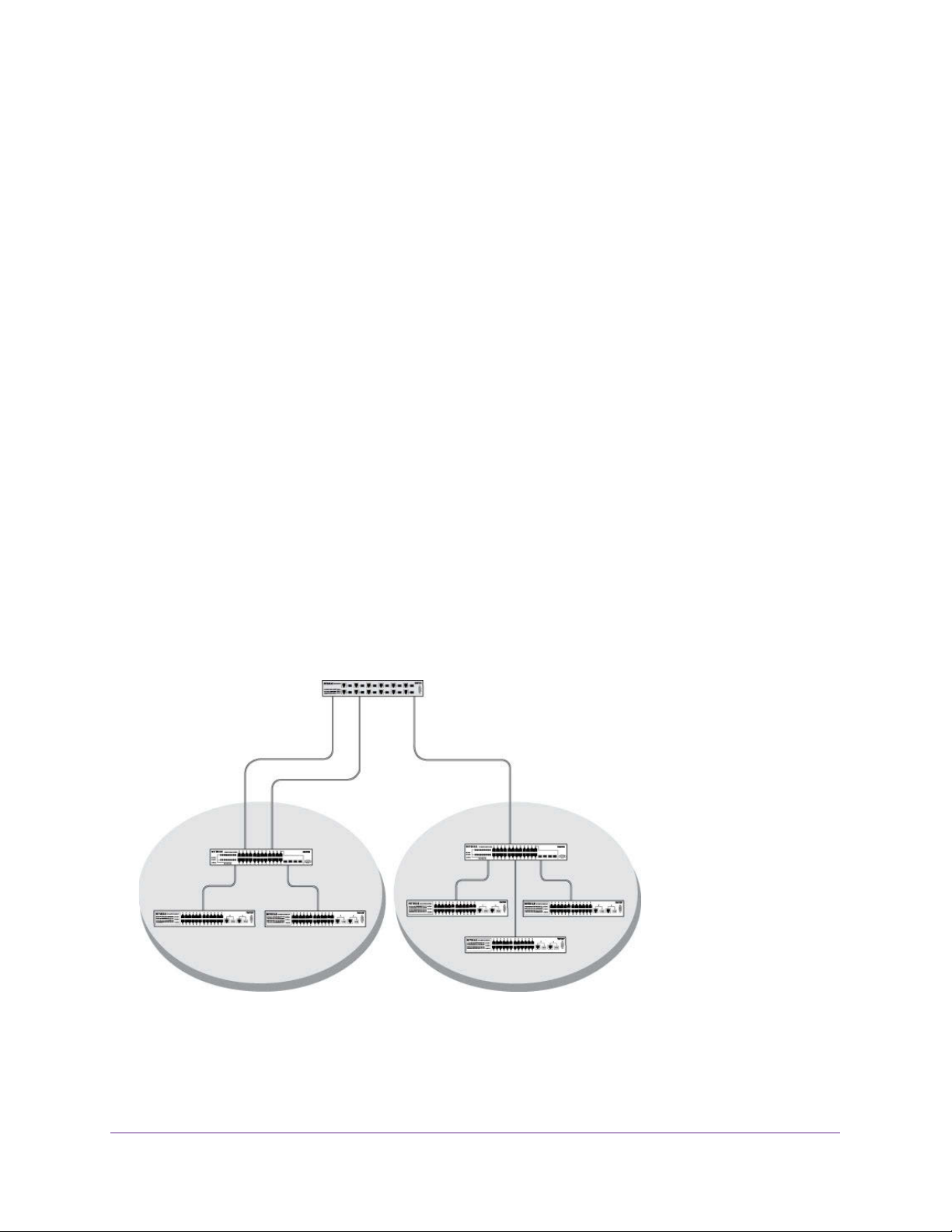
The diagram in this section shows a switch with four ports configured to handle the traffic for
two VLANs. Port 1/0/2 handles traffic for both VLANs, while port 1/0/1 is a member of VLAN
2 only, and ports 1/0/3 and 1/0/4 are members of VLAN 3 only. The script following the
diagram shows the commands you would use to configure the switch as shown in the
diagram.
Layer 3 switch
Port 1/0/2 VLAN
Router Port 1/3/1
192.150.3.1
Port 1/0/1
Layer 2
Switch
VLAN 10 VLAN 20
Port 1/0/3 VLAN
Router Port 1/3/2
192.150.4.1
Layer 2
Switch
Figure 1. Switch with 4 ports configured for traffic from 2 VLANs
The following examples show how to create VLANs, assign ports to the VLANs, and assign a
VLAN as the default VLAN to a port.
VLANs
19
Page 20
Managed Switches
Create Two VLANs
The example is shown as CLI commands and as a web interface procedure.
CLI: Create Two VLANs
Use the following commands to create two VLANs and to assign the VLAN IDs while leaving
the names blank.
(Netgear Switch) #vlan database
(Netgear Switch) (Vlan)#vlan 2
(Netgear Switch) (Vlan)#vlan 3
(Netgear Switch) (Vlan)#exit
Web Interface: Create Two VLANs
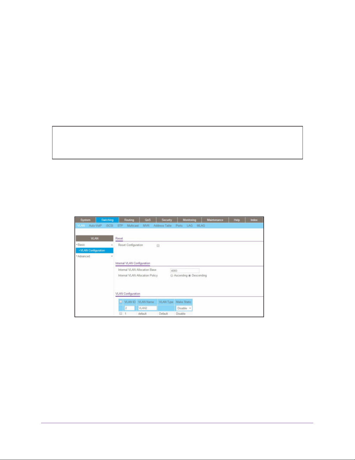
1. Create VLAN2.
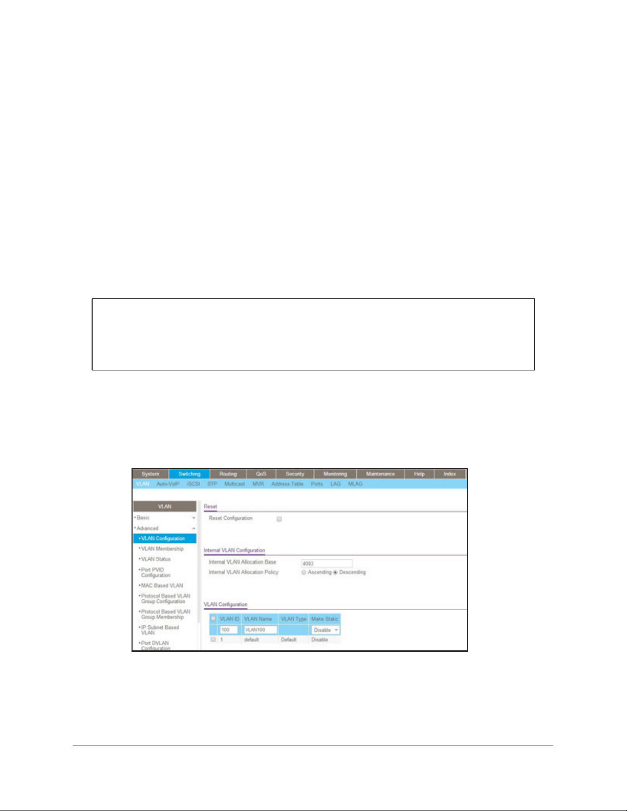
a. Select Switching > VLAN > Basic > VLAN Configuration.
A screen similar to the following displays.
b. Enter the following information:
• In the VLAN ID field, enter 2.
• In the VLAN Name field, enter VLAN2.
• In the VLAN Type list, select Static.
c. Click Add.
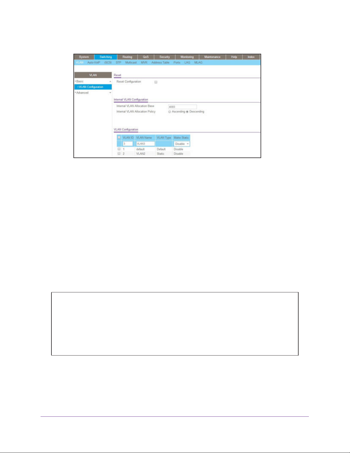
2. Create VLAN3.
a. Select Switching > VLAN > Basic > VLAN Configuration.
VLANs
20
Page 21
Managed Switches
A screen similar to the following displays.
b. Enter the following information:
• In the VLAN ID field, enter 3.
• In the VLAN Name field, enter VLAN3.
• In the VLAN Type list, select Static.
c. Click Add.
Assign Ports to VLAN 2
This sequence shows how to assign ports to VLAN2, and to specify that frames will always
be transmitted tagged from all member ports and that untagged frames will be rejected on
receipt.
CLI: Assign Ports to VLAN 2
(Netgear Switch) #config
(Netgear Switch) (Config)#interface range 1/0/1-1/0/2
(Netgear Switch) (conf-if-range-1/0/1-1/0/2)#vlan participation include 2
(Netgear Switch) (conf-if-range-1/0/1-1/0/2)#vlan acceptframe vlanonly
(Netgear Switch) (conf-if-range-1/0/1-1/0/2)#vlan pvid 2
(Netgear Switch) (conf-if-range-1/0/1-1/0/2)#exit
(Netgear Switch) (Config)#vlan port tagging all 2
(Netgear Switch) (Config)#
VLANs
21
Page 22
Managed Switches
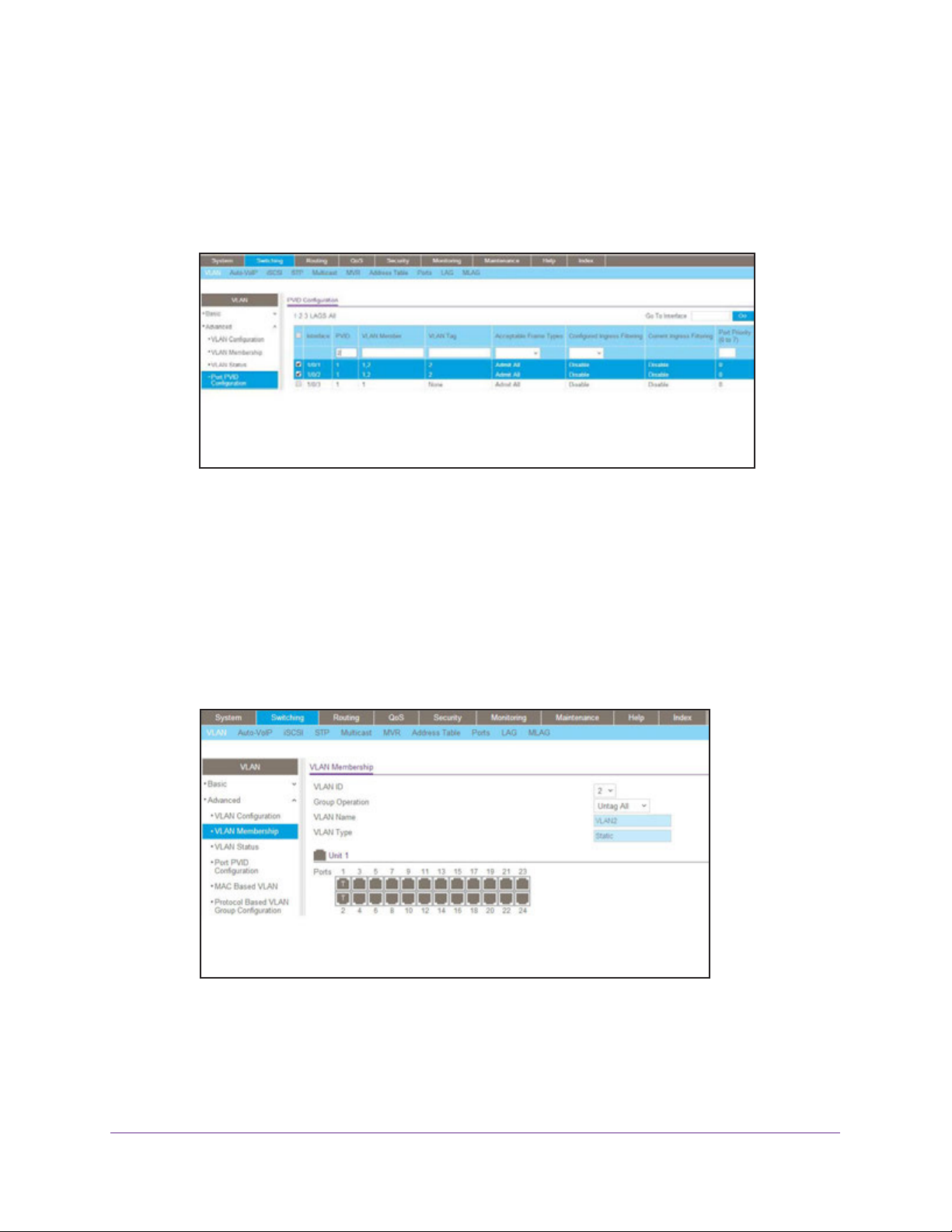
Web Interface: Assign Ports to VLAN 2
1. Assign ports to VLAN2.
a. Select Switching > VLAN > Advanced > VLAN Membership.
A screen similar to the following displays.
b. In the VLAN ID list, select 2.
c. Click Unit 1. The ports display.
d. Click the gray boxes under ports 1 and 2 until T displays.
The T specifies that the egress packet is tagged for the ports.
e. Click Apply to save the settings.
2. Specify that only tagged frames will be accepted on ports 1/0/1 and 1/0/2.
a. Select Switching > VLAN > Advanced > Port PVID Configuration.
A screen similar to the following displays.
b. Under PVID Configuration, scroll down and select the check box for Interface 1/0/1.
Then scroll down and select the Interface 1/0/2 check box.
VLANs
22
Page 23
Managed Switches
c. Enter the following information:
• In the Acceptable Frame Type polyhedron list, select VLAN Only.
• In the PVID (1 to 4093) field, enter 2.
d. Click Apply to save the settings.
Create Three VLANs
The example is shown as CLI commands and as a web interface procedure.
CLI: Create Three VLANs
Use the following commands to create three VLANs and to assign the VLAN IDs while
leaving the names blank.
(Netgear Switch) #vlan database
(Netgear Switch) (Vlan)#vlan 100
(Netgear Switch) (Vlan)#vlan 101
(Netgear Switch) (Vlan)#vlan 102
(Netgear Switch) (Vlan)#exit
Web Interface: Create Three VLANs
1. Create VLAN100.
a. Select Switching > VLAN > Basic > VLAN Configuration.
A screen similar to the following displays.
b. Enter the following information:
• In the VLAN ID field, enter 100.
• In the VLAN Name field, enter VLAN100.
c. Click Add.
VLANs
23
Page 24

Managed Switches
2. Create VLAN101.
a. Select Switching > VLAN > Basic > VLAN Configuration.
A screen similar to the following displays.
b. Enter the following information:
• In the VLAN ID field, enter 101.
• In the VLAN Name field, enter VLAN101.
c. Click Add.
3. Create VLAN102.
a. Select Switching > VLAN > Basic > VLAN Configuration.
A screen similar to the following displays.
b. Enter the following information:
• In the VLAN ID field, enter 102.
• In the VLAN Name field, enter VLAN102.
c. Click Add.
VLANs
24
Page 25
Managed Switches
Assign Ports to VLAN 3
This example shows how to assign the ports that will belong to VLAN 3, and to specify that
untagged frames will be accepted on port 1/0/4. Note that port 1/0/2 belongs to both VLANs
and that port 1/0/1 can never belong to VLAN 3.
CLI: Assign Ports to VLAN 3
(Netgear Switch) (Config)#interface range 1/0/2-1/0/4
(Netgear Switch) (conf-if-range-1/0/2-1/0/4)#vlan participation include 3
(Netgear Switch) (conf-if-range-1/0/2-1/0/4)#exit
(Netgear Switch) (Config)#interface 1/0/4
(Netgear Switch) (Interface 1/0/4)#vlan acceptframe all
(Netgear Switch) (Interface 1/0/4)#exit
(Netgear Switch) (Config)#exit
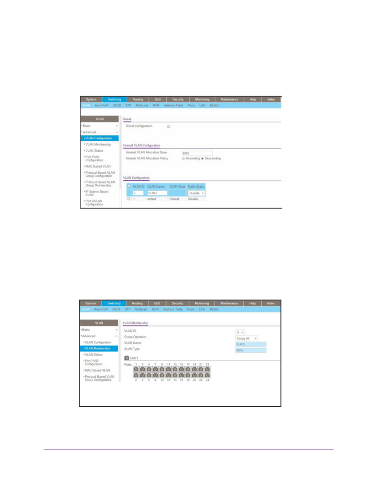
Web Interface: Assign Ports to VLAN 3
1. Assign ports to VLAN3.
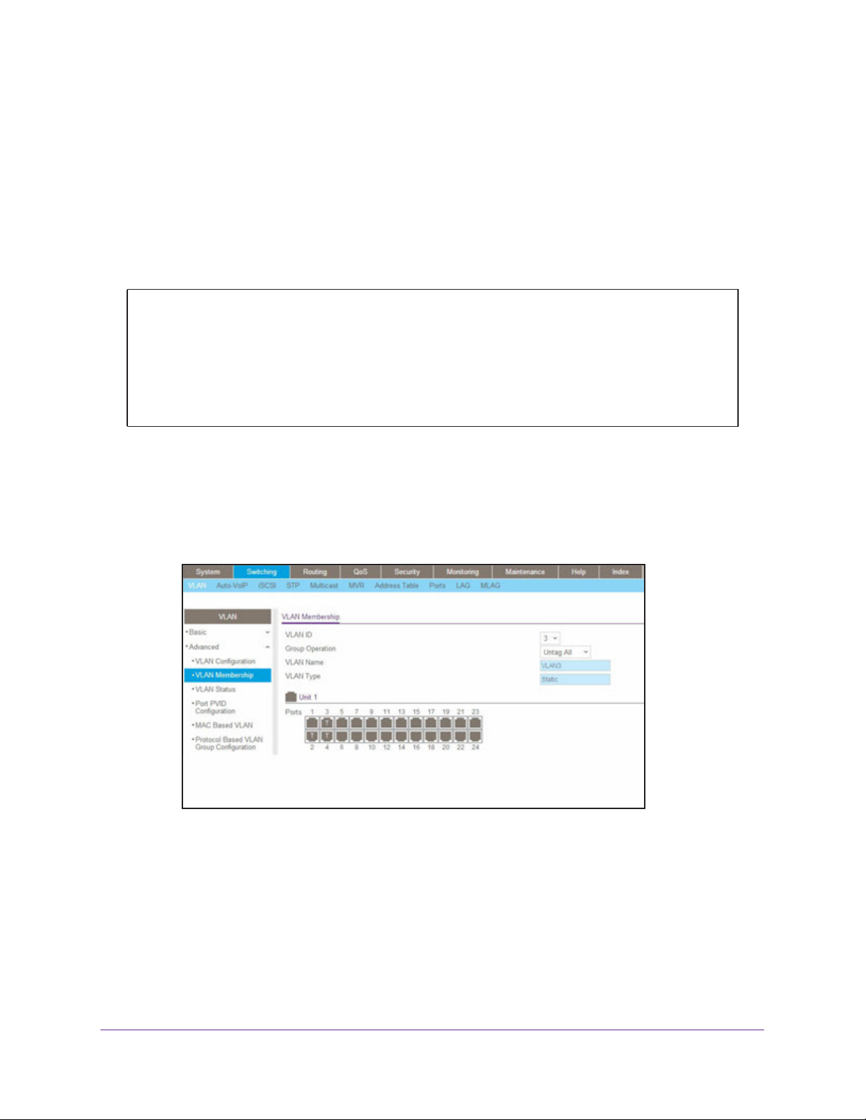
a. Select Switching > VLAN > Advanced > VLAN Membership.
A screen similar to the following displays.
b. In the VLAN ID list, select 3.
c. Click Unit 1. The ports display.
d. Click the gray boxes under ports 2, 3, and 4 until T displays.
The T specifies that the egress packet is tagged for the ports.
e. Click Apply to save the settings.
2. Specify that untagged frames will be accepted on port 1/0/4.
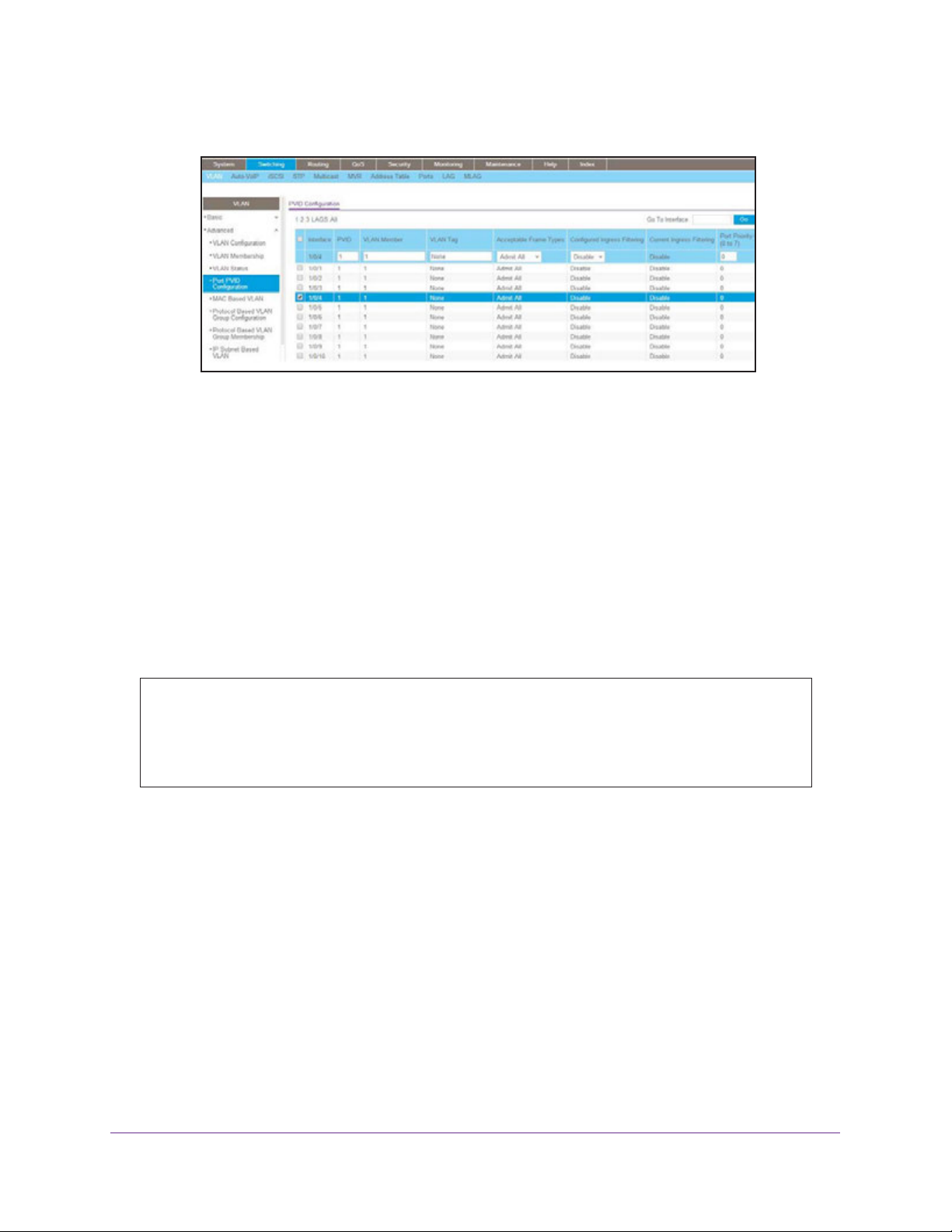
a. Select Switching > VLAN > Advanced > Port PVID Configuration.
VLANs
25
Page 26
Managed Switches
A screen similar to the following displays.
b. Scroll down and select the Interface 1/0/4 check box.
Now 1/0/4 appears in the Interface field at the top.
c. In the Acceptable Frame Types list, select Admit All.
d. Click Apply to save the settings.
Assign VLAN 3 as the Default VLAN for Port 1/0/2
This example shows how to assign VLAN 3 as the default VLAN for port 1/0/2.
CLI: Assign VLAN 3 as the Default VLAN for Port 1/0/2
(Netgear Switch) #config
(Netgear Switch) (Config)#interface 1/0/2
(Netgear Switch) (Interface 1/0/2)#vlan pvid 3
(Netgear Switch) (Interface 1/0/2)#exit
(Netgear Switch) (Config)#exit
VLANs
26
Page 27
Managed Switches
Web Interface: Assign VLAN 3 as the Default VLAN for Port 1/0/2
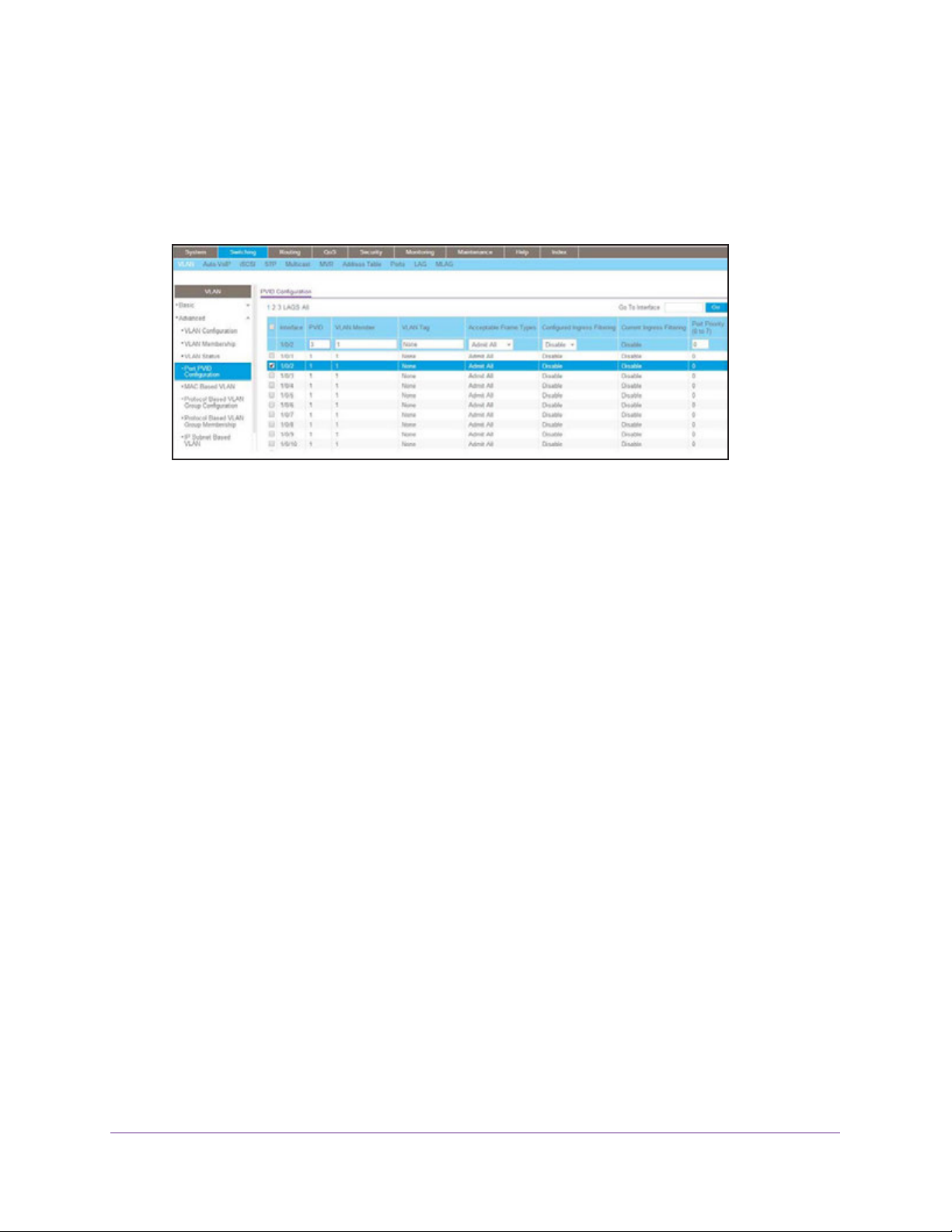
1. Select Switching > VLAN > Advanced > Port PVID Configuration.
A screen similar to the following displays.
2. Under PVID Configuration, scroll down and select the Interface 1/0/2 check box. Now 1/0/2
appears in the Interface field at the top.
3. In the PVID (1 to 4093) field, enter 3.
4. Click Apply to save the settings.
Create a MAC-Based VLAN
The MAC-based VLAN feature allows incoming untagged packets to be assigned to a VLAN
and thus classify traffic based on the source MAC address of the packet.
You define a MAC to VLAN mapping by configuring an entry in the MAC to VLAN table. An
entry is specified using a source MAC address and the appropriate VLAN ID. The MAC to
VLAN configurations are shared across all ports of the device (i.e., there is a system-wide
table that has MAC address to VLAN ID mappings).
When untagged or priority tagged packets arrive at the switch and entries exist in the MAC to
VLAN table, the source MAC address of the packet is looked up. If an entry is found, the
corresponding VLAN ID is assigned to the packet. If the packet is already priority tagged it
will maintain this value; otherwise, the priority will be set to 0 (zero). The assigned VLAN ID is
verified against the VLAN table. If the VLAN is valid, ingress processing on the packet
continues; otherwise, the packet is dropped. This implies that you can configure a MAC
address mapping to a VLAN that has not been created on the system.
VLANs
27
Page 28

Managed Switches
CLI: Create a MAC-Based VLAN
1. Create VLAN3.
(Netgear Switch)#vlan database
(Netgear Switch)(Vlan)#vlan 3
(Netgear Switch)(Vlan)#exit
2. Add port 1/0/23 to VLAN3.
(Netgear Switch)#config
(Netgear Switch)(Config)#interface 1/0/23
(Netgear Switch)(Interface 1/0/23)#vlan participation include 3
(Netgear Switch)(Interface 1/0/23)#vlan pvid 3
(Netgear Switch)(Interface 1/0/23)#exit
3. Map MAC 00:00:0A:00:00:02 to VLAN3.
(Netgear Switch)(Config)#exit
(Netgear Switch)#vlan data
(Netgear Switch)(Vlan)#vlan association mac 00:00:00A:00:00:02 3
(Netgear Switch)(Vlan)#exit
4. Add all the ports to VLAN3.
(Netgear Switch)#config
(Netgear Switch)(Config)#interface range 1/0/1-1/0/28
(Netgear Switch)(conf-if-range-1/0/1-1/0/28)#vlan participation include 3
(Netgear Switch)(conf-if-range-1/0/1-1/0/28)#exit
(Netgear Switch)(Config)#exit
VLANs
28
Page 29
Managed Switches
Web Interface: Assign a MAC-Based VLAN
1. Create VLAN3.
a. Select Switching > VLAN > Basic > VLAN Configuration.
A screen similar to the following displays.
b. Enter the following information:
• In the VLAN ID field, enter 3.
• In the VLAN Name field, enter VLAN3.
• In the VLAN Type list, select Static.
c. Click Add.
2. Assign ports to VLAN3.
a. Select Switching > VLAN > Advanced > VLAN Membership.
A screen similar to the following displays.
b. In the VLAN ID list, select 3.
c. Click Unit 1. The ports display.
VLANs
29
Page 30
Managed Switches
d. Click the gray box before Unit 1 until U displays.
e. Click Apply.
3. Assign VPID3 to port 1/0/23.
a. Select Switching > VLAN > Advanced > Port PVID Configuration.
A screen similar to the following displays.
b. Scroll down and select the 1/0/23 check box.
c. In the PVID (1 to 4093) field, enter 3.
d. Click Apply to save the settings.
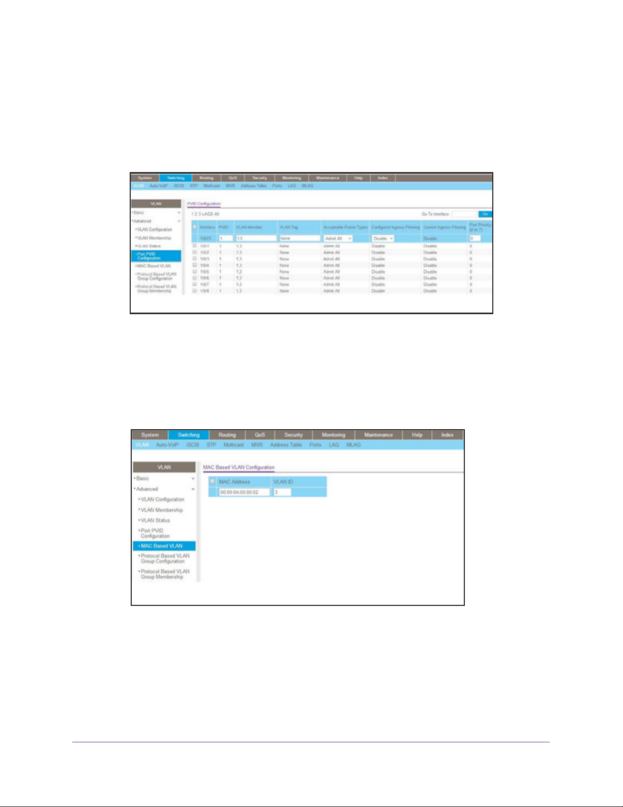
4. Map the specific MAC to VLAN3.
a. Select Switching > VLAN > Advanced > MAC based VLAN.
A screen similar to the following displays.
b. Enter the following information:
• In the MAC Address field, enter 00:00:0A:00:00:02.
• In the PVID (1 to 4093) field, enter 3.
c. Click Add.
VLANs
30
Page 31

Managed Switches
Create a Protocol-Based VLAN
Create two protocol VLAN groups. One is for IPX and the other is for IP/ARP. The untagged
IPX packets are assigned to VLAN 4, and the untagged IP/ARP packets are assigned to
VLAN 5.
CLI: Create a Protocol-Based VLAN
1. Create a VLAN protocol group vlan_ipx based on IPX protocol.
(Netgear Switch)#config
(Netgear Switch)(Config)#vlan protocol group 1
(Netgear Switch)(Config)#vlan protocol group name 1 "vlan_ipx"
(Netgear Switch)(Config)#vlan protocol group add protocol 1 ethertype ipx
2. Create a VLAN protocol group vlan_ipx based on IP/ARP protocol.
(Netgear Switch)(Config)#vlan protocol group 2
(Netgear Switch)(Config)#vlan protocol group name 2 "vlan_ip"
(Netgear Switch)(Config)#vlan protocol group add protocol 2 ethertype ip
(Netgear Switch)(Config)#vlan protocol group add protocol 2 ethertype arp
(Netgear Switch)(Config)#exit
3. Assign VLAN protocol group 1 to VLAN 4.
(Netgear Switch)#vlan database
(Netgear Switch)(Vlan)#vlan 4
(Netgear Switch)(Vlan)#vlan 5
(Netgear Switch)(Vlan)#protocol group 1 4
4. Assign VLAN protocol group 2 to VLAN 5.
(Netgear Switch)(Vlan)#protocol group 2 5
5. Enable protocol VLAN group 1 and 2 on the interface.
(Netgear Switch)(Vlan)#exit
(Netgear Switch)#config
(Netgear Switch)(Config)#interface 1/0/11
(Netgear Switch)(Interface 1/0/11)#protocol vlan group 1
(Netgear Switch)(Interface 1/0/11)#protocol vlan group 2
(Netgear Switch)(Interface 1/0/11)#exit
VLANs
31
Page 32

Managed Switches
Web Interface: Create a Protocol-Based VLAN
1. Create VLAN4 and VLAN5.
Create VLAN4.
a. Select Switching > VLAN > Basic > VLAN Configuration.
A screen similar to the following displays.
b. Enter the following information:
In the VLAN ID field, enter 4.
In the VLAN Name field, enter VLAN4.
In the VLAN Type list, select Static.
c. Click Add.
Create VLAN5.
a. Select Switching > VLAN > Basic > VLAN Configuration.
A screen similar to the following displays.
VLANs
32
Page 33

Managed Switches
b. Enter the following information:
In the VLAN ID field, enter 5.
In the VLAN Name field, enter VLAN5.
In the VLAN Type list, select Static.
c. Click Add.
2. Create the protocol-based VLAN group vlan_ipx.
a. Select Switching > VLAN > Advanced > Protocol Based VLAN Group
Configuration.
A screen similar to the following displays.
Enter the following information:
• In the Group ID field, enter 1.
• In the Group Name field, enter vlan_ipx.
• In the Protocol list, enter ipx.
• In the VLAN ID field, enter 4.
b. Click Add.
3. Create the protocol-based VLAN group vlan_ip.
a. Select Switching > VLAN >Advanced > Protocol Based VLAN Group
Configuration.
VLANs
33
Page 34

Managed Switches
A screen similar to the following displays.
b. Enter the following information:
• In the Group ID field, enter 2.
• In the Group Name field, enter vlan_ip.
• In the Protocol list, select IP and ARP while holding down the Ctrl key.
• In the VLAN field, enter 5.
c. Click Add.
4. Add port 11 to the group vlan_ipx.
a. Select Switching > VLAN > Advanced > Protocol Based VLAN Group
Membership.
A screen similar to the following displays.
b. In the Group ID list, select 1.
c. Click the gray box under port 11. A check mark displays in the box.
d. Click the Apply button.
VLANs
34
Page 35

Managed Switches
5. Add port 11 to the group vlan_ip.
a. Select Switching > VLAN > Advanced > Protocol Based VLAN Group
Membership.
A screen similar to the following displays.
b. In the Group ID list, select 2.
c. Click the gray box under port 11. A check mark displays in the box.
d. Click Apply.
Virtual VLANs: Create an IP Subnet–Based VLAN
In an IP subnet–based VLAN, all the end workstations in an IP subnet are assigned to the
same VLAN. In this VLAN, users can move their workstations without reconfiguring their
network addresses. IP subnet VLANs are based on Layer 3 information from packet headers.
The switch makes use of the network-layer address (for example, the subnet address for
TCP/IP networks) in determining VLAN membership. If a packet is untagged or priority
tagged, the switch associates the packet with any matching IP subnet classification. If no IP
subnet classification can be made, the packet is subjected to the normal VLAN classification
rules of the switch. This IP subnet capability does not imply a routing function or that the
VLAN is routed. The IP subnet classification feature affects only the VLAN assignment of a
packet. Appropriate 802.1Q VLAN configuration must exist in order for the packet to be
switched.
VLANs
35
Page 36

Managed Switches
1/0/24
PC 2
10.100.5.30
PC 1
10.100.5.1
1/0/1
Switch
Figure 2. IP subnet–based VLAN
CLI: Create an IP Subnet–Based VLAN
(Netgear Switch) #vlan database
(Netgear Switch) (Vlan)#vlan 2000
(Netgear Switch) (Vlan)#vlan association subnet 10.100.0.0 255.255.0.0 2000
(Netgear Switch) (Vlan)#exit
Create an IP subnet–based VLAN 2000.
(Netgear Switch) #config
(Netgear Switch) (Config)#interface range 1/0/1-1/0/24
(Netgear Switch) (conf-if-range-1/0/1-1/0/24)# vlan participation include 2000
(Netgear Switch) (conf-if-range-1/0/1-1/0/24)#exit
(Netgear Switch) (Config)#
Assign all the ports to VLAN 2000.
(Netgear Switch) #show mac-addr-table vlan 2000
MAC Address Interface Status
----------------- --------- -----------00:00:24:58:F5:56 1/0/1 Learned
00:00:24:59:00:62 1/0/24 Learned
VLANs
36
Page 37

Managed Switches
Web Interface: Create an IP Subnet–Based VLAN
1. Create VLAN 2000.
a. Select Switching > VLAN > Basic > VLAN Configuration.
A screen similar to the following displays.
b. Enter the following information:
• In the VLAN ID field, enter 2000.
• In the VLAN Type list, select Static.
c. Click Add.
2. Assign all the ports to VLAN 2000.
a. Select Switching > VLAN > Advanced > VLAN Membership.
A screen similar to the following displays.
b. In the VLAN ID list, select 2000.
c. Click Unit 1. The ports display.
d. Click the gray box before Unit 1 until U displays.
VLANs
37
Page 38

Managed Switches
e. Click Apply.
3. Associate the IP subnet with VLAN 2000.
a. Select Switching > VLAN > Advanced > IP Subnet Based VLAN.
A screen similar to the following displays.
b. Enter the following information:
• In the IP Address field, enter 10.100.0.0.
• In the Subnet Mask field, enter 255.255.0.0.
• In the VLAN (1 to 4093) field, enter 2000.
c. Click Add.
Voice VLANs
The voice VLAN feature enables switch ports to carry voice traffic with defined priority to
enable separation of voice and data traffic coming onto port. Voice VLAN ensures that the
sound quality of an IP phone does not deteriorate when the data traffic on the port is high.
Also, the inherent isolation provided by VLANs ensures that inter-VLAN traffic is under
management control and that clients attached to the network cannot initiate a direct attack on
voice components.
Note: For more information about voice VLANs, seeAuto VoIP on page 255.
VLANs
38
Page 39

PBX
Managed Switches
1/0/1
Switch
1/0/2
VoIP
phone
PC
1/0/3
VoIP
phone
PC
Voice traffic
Data traffic
Figure 3. Voice VLAN
The script in this section shows how to configure Voice VLAN and prioritize the voice traffic.
Here the Voice VLAN mode is in VLAN ID 10.
CLI: Configure Voice VLAN and Prioritize Voice Traffic
1. Create VLAN 10.
(Netgear Switch) #vlan database
(Netgear Switch) (Vlan)#vlan 10
(Netgear Switch) (Vlan)#exit
VLANs
39
Page 40

Managed Switches
2. Include the ports 1/0/1 and 1/0/2 in VLAN 10.
(Netgear Switch) (Config)#interface range 1/0/1-1/0/2
(Netgear Switch) (conf-if-range-1/0/1-1/0/2)#vlan participation include 10
(Netgear Switch) (conf-if-range-1/0/1-1/0/2)#vlan tagging 10
(Netgear Switch) (conf-if-range-1/0/1-1/0/2)#exit
3. Configure Voice VLAN globally.
(Netgear Switch) (Config)# voice vlan
4. Configure Voice VLAN mode in the interface 1/0/2.
(Netgear Switch) (Config)#interface 1/0/2
(Netgear Switch) (Interface 1/0/2)#voice vlan 10
(Netgear Switch) (Interface 1/0/2)#exit
5. Create the DiffServ class ClassVoiceVLAN.
(Netgear Switch) (Config)#class-map match-all ClassVoiceVLAN
6. Configure VLAN 10 as the matching criteria for the class.
(Netgear Switch) (Config-classmap)#match vlan 10
7. Create the DiffServ policy PolicyVoiceVLAN.
(Netgear Switch) (Config)#policy-map PolicyVoiceVLAN in
8. Map the policy and class and assign them to the higher-priority queue.
(Netgear Switch) (Config-policy-map)#class ClassVoiceVLAN
(Netgear Switch) (Config-policy-classmap)#assign-queue 3
(Netgear Switch) (Config-policy-classmap)#exit
9. Assign it to interfaces 1/0/1 and 1/0/2.
(Netgear Switch) (Config)#interface range 1/0/1-1/0/2
(Netgear Switch) (conf-if-range-1/0/1-1/0/2)# service-policy in PolicyVoiceVLAN
VLANs
40
Page 41

Managed Switches
Web Interface: Configure Voice VLAN and Prioritize Voice Traffic
1. Create VLAN 10.
a. Select Switching > VLAN > Basic > VLAN Configuration.
A screen similar to the following displays.
b. In the VLAN ID field, enter 10.
c. In the VLAN Name field, enter Voice VLAN.
d. Click Add.
2. Include the ports 1/0/1 and 1/0/2 in VLAN 10.
a. Select Switching > VLAN > Advanced > VLAN Membership.
A screen similar to the following displays.
b. In the VLAN Membership table, in the VLAN ID list, select 10.
c. Select Port 1 and Port 2 as tagged.
d. Click Apply.
VLANs
41
Page 42

Managed Switches
3. Configure Voice VLAN globally.
a. Select Switching > VLAN > Advanced > Voice VLAN Configuration.
A screen similar to the following displays.
b. For Admin Mode, select the Enable radio button.
c. Click Apply.
4. Configure Voice VLAN mode in the interface 1/0/2.
a. Select Switching > VLAN > Advanced > Voice VLAN Configuration.
b. Select the 1/0/2 check box.
c. In the Interface Mode list, select VLAN ID.
d. In the Value field, enter 10.
A screen similar to the following displays.
e. Click Apply.
VLANs
42
Page 43

Managed Switches
5. Create the DiffServ class ClassVoiceVLAN.
a. Select QoS > Advanced > DiffServ > Class Configuration.
A screen similar to the following displays.
b. In the Class Name field, enter ClassVoiceVLAN.
c. In the Class Type list, select All.
d. Click Add. The Class Name screen displays, as shown in the next step in this
procedure.
6. Configure matching criteria for the class as VLAN 10.
a. Select QoS > DiffServ > Advanced > Class Configuration.
A screen similar to the following displays.
b. Click the class ClassVoiceVLAN.
c. In the DiffServ Class Configuration table, select VLAN.
d. In the VLAN ID field, enter 10.
VLANs
43
Page 44

Managed Switches
A screen similar to the following displays.
e. Click Apply.
7. Create the DiffServ policy PolicyVoiceVLAN.
a. Select QoS > DiffServ > Advanced > Policy Configuration.
A screen similar to the following displays.
b. In the Policy Name field, enter PolicyVoiceVLAN.
c. In the Policy Type list, select In.
d. In the Member Class list, select ClassVoiceVLAN.
e. Click Add.
The Policy Configuration screen displays, as shown in the next step in this procedure.
8. Map the policy and class and assign them to the higher-priority queue.
a. Select QoS > DiffServ > Advanced > Policy Configuration.
VLANs
44
Page 45

Managed Switches
A screen similar to the following displays.
b. Click the Policy PolicyVoiceVLAN.
A screen similar to the following displays.
c. In the field next to the Assign Queue radio button, select 3.
d. Click Apply.
9. Assign it to interfaces 1/0/1 and 1/0/2.
a. Select QoS > DiffServ > Advanced > Service Interface Configuration.
VLANs
45
Page 46

Managed Switches
A screen similar to the following displays.
b. Select the check boxes for Interfaces 1/0/1 and 1/0/2.
c. Set the Policy Name field as PolicyVoiceVLAN.
d. Click Apply.
Configure GARP VLAN Registration Protocol
Generic Attribute Registration Protocol (GARP) VLAN Registration Protocol (GVRP) provides
IEEE 802.1Q-compliant VLAN pruning and dynamic VLAN creation on 802.1Q-tagged ports.
With GVRP, a switch can exchange VLAN configuration information with other GVRP
switches, prune unnecessary broadcast and unknown unicast traffic, and create and manage
VLANs dynamically on switches that are connected through 802.1Q-tagged ports.
1/0/24 Tagged
1/0/11
GVRP Switch A
Figure 4. GVRP configuration
GVRP Switch B
VLANs
46
Page 47

Managed Switches
CLI: Enable GVRP
1. On Switch A, create VLANs 1000, 2000, and 3000, and add port 1/0/24 as a tagged port
to VLANs 1000, 2000, and 3000.
(Netgear Switch) #vlan database
(Netgear Switch) (Vlan)#vlan 1000,2000,3000
(Netgear Switch) (Vlan)#exit
(Netgear Switch) #config
(Netgear Switch) (Config)#interface 1/0/24
(Netgear Switch) (Interface 1/0/24)#vlan participation include 1000
(Netgear Switch) (Interface 1/0/24)#vlan participation include 2000
(Netgear Switch) (Interface 1/0/24)#vlan participation include 3000
(Netgear Switch) (Interface 1/0/24)#vlan tagging 1000,2000,3000
2. On Switch A, enable GVRP.
(Netgear Switch) #set gvrp adminmode
(Netgear Switch) #config
(Netgear Switch) (Config)#interface 1/0/24
(Netgear Switch) (Interface 1/0/24)#set gvrp interfacemode
3. On Switch B, enable GVRP.
(Netgear Switch) #set gvrp adminmode
(Netgear Switch) #config
(Netgear Switch) (Config)#interface 1/0/11
(Netgear Switch) (Interface 1/0/11)#set gvrp interfacemode
VLANs
47
Page 48

Managed Switches
4. On Switch B, verify that VLANs 1000, 2000, and 3000 were created.
(Netgear Switch) #show vlan
Maximum VLAN Entries........................... 1024
VLAN Entries Currently in Use.................. 5
VLAN ID VLAN Name VLAN Type
------- -------------------------------- ------------------1 default Default
2 Auto VoIP AUTO VoIP
1000 Dynamic (GVRP)
2000 Dynamic (GVRP)
3000 Dynamic (GVRP)
(Netgear Switch) #show vlan 1000
VLAN ID: 1000
VLAN Name:
VLAN Type: Dynamic (GVRP)
Interface Current Configured Tagging
---------- -------- ----------- -------1/0/1 Exclude Autodetect Untagged
1/0/2 Exclude Autodetect Untagged
1/0/3 Exclude Autodetect Untagged
1/0/4 Exclude Autodetect Untagged
1/0/5 Exclude Autodetect Untagged
1/0/6 Exclude Autodetect Untagged
1/0/7 Exclude Autodetect Untagged
1/0/8 Exclude Autodetect Untagged
1/0/9 Exclude Autodetect Untagged
1/0/10 Exclude Autodetect Untagged
1/0/11 Include Autodetect Tagged
1/0/12 Exclude Autodetect Untagged
1/0/13 Exclude Autodetect Untagged
1/0/14 Exclude Autodetect Untagged
1/0/15 Exclude Autodetect Untagged
1/0/16 Exclude Autodetect Untagged
VLANs
48
Page 49

Managed Switches
Web Interface: Configure GVRP on switch A
1. On Switch A, create VLANs 1000, 2000, and 3000:
a. Select Switching > VLAN > Advanced > VLAN Configuration.
A screen similar to the following displays.
b. In the VLAN ID field, enter 1000.
c. Click Add.
d. Repeat Step a through Step c to create VLANs 2000 and 3000.
2. Add port 1/0/24 as a tagged port to VLANs 1000, 2000, and 3000:
a. Select Switching > VLAN > Advanced > VLAN Membership.
A screen similar to the following displays.
a. From the VLAN ID menu, select 1000.
b. Click Unit 1.
The ports display.
c. Click the gray box under port 24 until T displays.
VLANs
49
Page 50

Managed Switches
T specifies that the switch tags egress packets for port 24.
d. Click Apply.
3. Enable GVRP globally:
a. Select Switching > VLAN > Advanced > GARP Switch Configuration.
A screen similar to the following displays.
b. Next to GVRP Mode, select the Enable radio button.
c. Click Apply.
4. Enable GVRP on port 1/0/24.
a. Select Switching > VLAN > Advanced > GARP Port Configuration.
A screen similar to the following displays.
b. Scroll down and select the check box that corresponds to interface 1/0/24.
The Interface field in the table heading displays 1/0/24.
VLANs
50
Page 51

Managed Switches
c. From the Port GVRP Mode menu, select Enable.
d. Click Apply.
Web Interface: Configure GVRP on Switch B
1. Enable GVRP globally:
a. Select Switching > VLAN > Advanced > GARP Switch Configuration.
A screen similar to the following displays.
b. Next to GVRP Mode, select the Enable radio button.
c. Click Apply.
2. Enable GVRP on port 1/0/11:
a. Select Switching > VLAN > Advanced > GARP Port Configuration.
A screen similar to the following displays.
VLANs
51
Page 52

Managed Switches
b. Scroll down and select the check box that corresponds to interface 1/0/11.
The Interface field in the table heading displays 1/0/11.
c. From the Port GVRP Mode menu, select Enable.
d. Click Apply.
Private VLANs
The Private VLANs feature separates a regular VLAN domain into two or more subdomains.
Each subdomain is defined (represented) by a primary VLAN and a secondary VLAN. The
primary VLAN ID is the same for all subdomains that belong to a private VLAN. The
secondary VLAN ID differentiates subdomains from each other and provides Layer 2 isolation
between ports of the same private VLAN.
There are three types of VLAN within a private VLAN:
• Primary VLAN. it forwards the traffic from the promiscuous ports to isolated ports,
community ports, and other promiscuous ports in the same private VLAN. Only one
primary VLAN can be configured per private VLAN. All ports within a private VLAN
share the same primary VLAN.
• Community VLAN. is a secondary VLAN. It forwards traffic between ports which
belong to the same community and to the promiscuous ports. There can be multiple
community VLANs per private VLAN.
• Isolated VLAN. is a secondary VLAN. It carries traffic from isolated ports to
promiscuous ports. Only one isolated VLAN can be configured per private VLAN.
There are three types of port designation within a private VLAN:
• Promiscuous port. belongs to a primary VLAN and can communicate with all
interfaces in the private VLAN, including other promiscuous ports, community ports,
and isolated ports.
• Community ports. These ports can communicate with other community ports and
promiscuous ports.
• Isolated ports. These can ONLY communicate with promiscuous ports.
The following figure shows how private VLANs can be extended across multiple switches
through inter-switch/stack links that transport primary, community, and isolated VLANs
between devices.
VLANs
52
Page 53

Managed Switches
Figure 5. Private VLANs
The following figure illustrates the private VLAN traffic flow . Five ports A, B, C, D, and E make
up a private VLAN. Port A is a promiscuous port which is associated with the primary VLAN
100. Ports B and C are the host ports which belong to the isolated VLAN 101. Ports D and E
are the community ports which are associated with community VLAN 102. Port F is the
inter-switch/stack link. It is configured to transmit VLANs 100, 101 and 102. Colored arrows
represent possible packet flow paths in the private VLAN domain.
Figure 6. Packet flow within a Private VLAN domain
VLANs
53
Page 54

Managed Switches
Assign Private-VLAN Types (Primary, Isolated, Community)
The example is shown as CLI commands and as a web interface procedure.
CLI: Assign Private-VLAN Type (Primary, Isolated, Community)
Use the following commands to assign VLAN 100 to primary VLAN, VLAN 101 to isolated
VLAN, and VLAN 102 to community VLAN.
(Netgear Switch) #config
(Netgear Switch) (Config)#vlan 100
(Netgear Switch) (Config)(Vlan) #private-vlan primary
(Netgear Switch) (Config)(Vlan) #exit
(Netgear Switch) (Config)#vlan 101
(Netgear Switch) (Config)(Vlan) #private-vlan isolated
(Netgear Switch) (Config)(Vlan) #exit
(Netgear Switch) (Config)#vlan 102
(Netgear Switch) (Config)(Vlan) #private-vlan community
(Netgear Switch) (Config)(Vlan) #end
Web Interface: Assign Private-VLAN Type (Primary, Isolated, Community)
1. Create VLAN 10.
a. Select Security > Traffic Control > Private VLAN > Private VLAN Type
Configuration.
A screen similar to the following displays.
VLANs
54
Page 55

Managed Switches
b. Under Private VLAN Type Configuration, select the VLAN ID 100 check box. Now
100 appears in the interface field at the top.
c. In the Private VLAN Type field, select Primary from the menu.
d. Click Apply to save the settings
2. Assign VLAN 101 as an isolated VLAN.
a. Select Security > Traffic Control > Private VLAN > Private VLAN Type
Configuration.
A screen similar to the following displays.
b. Under Private VLAN Type Configuration, select the VLAN ID 101 check box.
Now 101 appears in the interface field at the top.
c. In the Private VLAN Type field, select Isolated from the menu.
d. Click Apply to save the settings
3. Assign VLAN 102 to community VLAN.
a. Select Security > Traffic Control > Private VLAN > Private VLAN Type
Configuration.
A screen similar to the following displays.
VLANs
55
Page 56

Managed Switches
b. Under Private VLAN Type Configuration, select the VLAN ID 102 check box. Now
102 appears in the interface field at the top.
c. In the Private VLAN Type field, select Community from the menu.
d. Click Apply to save the settings.
Configure Private-VLAN Association
The example is shown as CLI commands and as a web interface procedure.
CLI: Configure Private-VLAN Association
Use the following commands to associate VLAN 101-102 (secondary VLAN) to VLAN 100
(primary VLAN).
(Netgear Switch) #config
(Netgear Switch) (Config)#vlan 100
(Netgear Switch) (Config)(Vlan) #private-vlan association 101-102
(Netgear Switch) (Config)(Vlan) #end
Web Interface: Configure Private-VLAN Association
1. Associate VLAN 101-102 (secondary VLAN) to VLAN 100 (primary VLAN).
a. Select Security > Traffic Control > Private VLAN > Private VLAN Association
Configuration.
A screen similar to the following displays.
b. Under Private VLAN Association Configuration, select the VLAN ID 100.
c. In the Secondary VLAN(s) field, type 101-102.
d. Click Apply to save the settings.
VLANs
56
Page 57

Managed Switches
Configure Private-VLAN Port Mode (Promiscuous, Host)
The example is shown as CLI commands and as a web interface procedure.
CLI: Configure Private-VLAN Port Mode (Promiscuous, Host)
Use the following commands to assign port 1/0/1 to promiscuous port mode and ports
1/0/2-1/0/5 to host port mode.
(Netgear Switch) #config
(Netgear Switch) (Config)#interface 1/0/1
(Netgear Switch) (Interface 1/0/1)#switchport mode private-vlan promiscuous
(Netgear Switch) (Interface 1/0/1)#exit
(Netgear Switch) (Config)#interface 1/0/2-1/0/5
(Netgear Switch) (Interface 1/0/2-1/0/5)#switchport mode private-vlan host
(Netgear Switch) (Interface 1/0/2-1/0/5)#end
Web Interface: Configure Private-VLAN Port Mode (Promiscuous, Host)
1. Configure port 1/0/1 to promiscuous port mode.
a. Select Security > Traffic Control > Private VLAN > Private VLAN Port Mode
Configuration.
A screen similar to the following displays.
b. Under Private VLAN Port Mode Configuration, select the 1/0/1 interface check
box.
Now 1/0/1 appears in the Interface field at the top.
c. In the Port VLAN Mode field, select Promiscuous from the menu.
VLANs
57
Page 58

Managed Switches
d. Click Apply to save the settings.
2. Configure ports 1/0/2-1/0/5 to host port mode.
a. Select Security > Traffic Control > Private VLAN > Private VLAN Port Mode
Configuration.
A screen similar to the following displays.
b. Under Private VLAN Port Mode Configuration, select the 1/0/2 to 1/0/5 interface
check box.
c. In the Port VLAN Mode field, select Host from the menu.
d. Click Apply to save the settings.
Configure Private-VLAN Host Ports
The example is shown as CLI commands and as a web interface procedure.
CLI: Configure Private-VLAN Host Ports
Use the following commands to associate isolated ports 1/0/2-1/0/3 to a private-VLAN
(primary=100, secondary=101). Community ports 1/0/4-1/0/5 to a private-VLAN (primary=
100, secondary=102).
(Netgear Switch) #config
(Netgear Switch) (Config)#interface 1/0/2-1/0/3
(Netgear Switch) (Interface 1/0/2-1/0/3)#switchport private-vlan host-association
100 101
(Netgear Switch) (Interface 1/0/2-1/0/3)#exit
(Netgear Switch) (Config)#interface 1/0/4-1/0/5
(Netgear Switch) (Interface 1/0/4-1/0/5)#switchport private-vlan host-association
100 102
(Netgear Switch) (Interface 1/0/4-1/0/5)#end
VLANs
58
Page 59

Managed Switches
Web Interface: Assign Private-VLAN Port Host Ports
1. Associate isolated ports 1/0/2-1/0/3 to a private-VLAN (primary=100, secondary=101).
a. Select Security > Traffic Control > Private VLAN > Private VLAN Host Interface
Configuration.
A screen similar to the following displays.
b. Under Private VLAN Host Interface Configuration, select the 1/0/2 and 1/0/3
interface check box.
c. In the Host Primary VLAN field, enter 100.
d. In the Host Secondary VLAN field, enter 101.
e. Click Apply to save the settings.
2. Associate isolated ports 1/0/4-1/0/5 to a private-VLAN (primary=100, secondary=102).
a. Select Security > Traffic Control > Private VLAN > Private VLAN Host Interface
Configuration.
A screen similar to the following displays.
b. Under Private VLAN Host Interface Configuration, select the 1/0/4 and 1/0/5
interface check box.
VLANs
59
Page 60

Managed Switches
c. In the Host Primary VLAN field, enter 100.
d. In the Host Secondary VLAN field, enter 102.
e. Click Apply to save the settings.
Map Private-VLAN Promiscuous Port
The example is shown as CLI commands and as a web interface procedure.
CLI: Map Private-VLAN Promiscuous Port
Use the following commands to map private-VLAN promiscuous port 1/0/1 to a primary VLAN
(100) and to secondary VLANs (101-102).
(Netgear Switch) #config
(Netgear Switch) (Config)#interface 1/0/1
(Netgear Switch) (Interface 1/0/1)#switchport private-vlan mapping 100 101-102
(Netgear Switch) (Interface 1/0/1)#end
Web Interface: Map Private-VLAN Promiscuous Port
1. Map private-VLAN promiscuous port 1/0/1 to a primary VLAN (100) and to selected
secondary VLANs (101-102).
a. Select Security > Traffic Control > Private VLAN > Private VLAN Promiscuous
Interface Configuration.
A screen similar to the following displays.
b. Under Private VLAN Promiscuous Interface Configuration, select the 1/0/1
interface check box. Now 1/0/1 appears in the Interface field at the top.
c. In the Promiscuous Primary VLAN field, enter 100.
VLANs
60
Page 61

Managed Switches
d. In the Promiscuous Secondary VLAN field, enter 101-102.
e. Click Apply to save the settings
VLAN Access Ports and Trunk Ports
Using switch ports can minimize potential configuration errors. Switch ports also facilitate the
configuration of a VLAN by reducing the number of commands that you must enter. To
configure a port that is connected to an end user, use a switch port in access mode. To
configure a port that is connected to another switch, use a switch port in trunk mode.
In addition, to access mode and trunk mode, you can configure switch ports in general mode,
which is the default mode and does not restrict the configuration so you can configure the
port as needed.
The switch supports the following switch port modes, each with its own VLAN membership
rules:
• Access mode. In access mode, the following rules apply to switch ports:
- Ports belong to a single VLAN, for which the VID is the configured PVID.
- Ports are intended for end-point connections, which, in general, do not operate with
LANs and operate with tagged traffic.
- Ports accept both tagged and untagged traffic. (You cannot configurable whether the
ports accepts tagged or untagged traffic.)
- All egress traffic must be sent untagged.
- Ingress filtering is always enabled.
- Ports are intended for connecting end stations to the switch, especially when end
stations are incapable of generating VLAN tags.
• Trunk mode. In trunk mode, the following rules apply to switch ports:
- Ports can belong to as many VLANs as needed.
- Ports accept both incoming tagged and untagged traffic.
- All incoming untagged frames are tagged with the native VLAN as the VID.
- Egress frames are sent tagged for all VLANs other than the native VLAN. Frames that
belong to the native VLAN are sent without a VLAN tag.
- Ingress filtering is always enabled. If incoming frames are tagged correctly (that is,
tagged with a VID of one of the VLANs to which the port belongs), they are admitted.
- Ports are intended for connections between switches, for which the traffic is generally
tagged.
- If you configure a list with allowed VLANs, a trunk port becomes a member of VLANs
that are defined in the list with allowed VLANs.
• General mode. In general mode, the following rules apply to switch ports:
- By default, all ports are designated as general mode ports and belong to the default
VLAN.
- Ports conform to NETGEAR legacy switch behavior for switch ports.
VLANs
61
Page 62

Managed Switches
- You configure various VLAN parameters such as membership, tagging, and PVID by
using legacy commands.
- You can enable or disable ingress filtering.
The following figure shows a configuration with access ports and a trunk port.
PC1
PC2
Figure 7. Access and trunk ports
1/0/1 access port
in VLAN 1000
Switch
1/0/2 access port
in VLAN 2000
CLI: Configure a VLAN Trunk
1. Create VLAN 1000 and 2000.
(Netgear Switch) #vlan database
(Netgear Switch) (Vlan)#vlan 1000
(Netgear Switch) (Vlan)#vlan 2000
(Netgear Switch) (Vlan)#exit
1/0/3 trunk port
Network
that allows
LANs 1000 and 2000
2. Configure port 1/0/1 as an access port.
(Netgear Switch) #config
(Netgear Switch) (Config)#interface 1/0/1
(Netgear Switch) (Interface 1/0/1)#switchport mode access
(Netgear Switch) (Interface 1/0/1)#switchport access vlan 1000
(Netgear Switch) (Interface 1/0/1)#exit
(Netgear Switch) (Config)#
VLANs
62
Page 63

Managed Switches
3. Configure port 1/0/2 as an access port.
(Netgear Switch) #config
(Netgear Switch) (Config)#interface 1/0/2
(Netgear Switch) (Interface 1/0/2)#switchport mode access
(Netgear Switch) (Interface 1/0/2)#switchport access vlan 2000
(Netgear Switch) (Interface 1/0/2)#exit
(Netgear Switch) (Config)#
4. Configure port 1/0/3 as a trunk port.
(Netgear Switch) (Interface 1/0/3)#switchport mode trunk
(Netgear Switch) (Interface 1/0/3)#switchport trunk allowed vlan 1000,2000
5. Configure all incoming untagged packets to be tagged with the native VLAN ID.
(Netgear Switch) (Interface 1/0/3)#switchport trunk native vlan 1000
Web Interface: Configure a VLAN Trunk
1. Create VLAN 1000
a. Select Switching > VLAN > Advanced > VLAN Configuration.
A screen similar to the following displays.
b. In the VLAN ID field, enter 1000.
c. Click Add.
VLANs
63
Page 64

Managed Switches
A screen similar to the following displays.
d. In the VLAN ID field, enter 2000.
e. Click Add.
2. Configure port 1/0/1 as an access port in VLAN 1000.
a. Select Switching > VLAN > Advanced > VLAN Trunking Configuration.
A screen similar to the following displays.
b. Select the check box that corresponds to interface 1/0/1.
VLANs
64
Page 65

Managed Switches
The Interface field in the table heading displays 1/0/1.
c. In the Switchport Mode field, select Access.
d. In the Access VLAN ID field, select 1000.
e. Click Apply.
3. Configure port 1/0/2 as an access port in VLAN 2000.
a. Select Switching > VLAN > Advanced > VLAN Trunking Configuration.
A screen similar to the following displays.
b. Select the check box that corresponds to interface 1/0/2.
The Interface field in the table heading displays 1/0/2.
c. In the Switchport Mode field, select Access.
d. In the Access VLAN ID field, select 2000.
e. Click Apply.
4. Configure port 1/0/3 as a trunk port that allows VLANs 1000 and 2000.
a. Select Switching > VLAN > Advanced > VLAN Trunking Configuration.
A screen similar to the following displays.
VLANs
65
Page 66

Managed Switches
b. Select the check box that corresponds to interface 1/0/3.
The Interface field in the table heading displays 1/0/3.
c. In the Switchport Mode field, select Trunk.
d. In the Native VLAN ID field, select 2000.
Note: In this step, you configure incoming untagged packets to be tagged
with VLAN ID 2000. If you want the switch to drop untagged packets,
ignore this step.
e. In the Trunk Allowed VLANs field, enter 1000,2000.
f. Click Apply.
VLANs
66
Page 67

3. LAGs
Link Aggregation Groups
This chapter includes the following sections:
• Link Aggregation Concepts
• Add Ports to LAGs
3
67
Page 68

Managed Switches
Link Aggregation Concepts
Link aggregation allows the switch to treat multiple physical links between two endpoints as a
single logical link. All the physical links in a given LAG must operate in full-duplex mode at the
same speed. LAGs can be used to directly connect two switches when the traffic between
them requires high bandwidth and reliability , or to provide a higher-bandwidth connection to a
public network. Management functions treat a LAG as if it is a single physical port. You can
include a LAG in a VLAN. You can configure more than one LAG for a given switch.
Port 1/0/3
Server
LAG_10
Port 1/0/2
LAG_10
Layer 3 Switch
Subnet 3
Port 1/0/8
LAG 20
Layer 2 Switch
Subnet 2 Subnet 3
Figure 8. Example network with two LAGs
Port 1/0/9
LAG_20
LAGs offer the following benefits:
• Increased reliability and availability. If one of the physical links in the LAG goes down,
traffic is dynamically and transparently reassigned to one of the other physical links.
• Better use of physical resources. Traffic can be load-balanced across the physical links.
• Increased bandwidth. The aggregated physical links deliver higher bandwidth than each
individual link.
• Incremental increase in bandwidth. A physical upgrade could produce a tenfold increase
in bandwidth; LAG produces a twofold or fivefold increase, which is useful if only a small
increase is needed.
LAGs
68
Page 69

Managed Switches
Add Ports to LAGs
The example is shown as CLI commands and as a web interface procedure.
CLI: Add Ports to the LAGs
(Netgear Switch) #config
(Netgear Switch) (Config)#interface 0/2
(Netgear Switch) (Interface 0/2)#addport 1/1
(Netgear Switch) (Interface 0/2)#exit
(Netgear Switch) (Config)#interface 0/3
(Netgear Switch) (Interface 0/3)#addport 1/1
(Netgear Switch) (Interface 0/3)#exit
(Netgear Switch) (Config)#interface 0/8
(Netgear Switch) (Interface 0/8)#addport 1/2
(Netgear Switch) (Interface 0/8)#exit
(Netgear Switch) (Config)#interface 0/9
(Netgear Switch) (Interface 0/9)#addport 1/2
(Netgear Switch) (Interface 0/9)#exit
(Netgear Switch) (Config)#exit
Web Interface: Add Ports to LAGs
1. Add ports to lag_10.
a. Select Switching > LAG > LAG Membership.
A screen similar to the following displays.
b. In the LAG ID list, select LAG 1.
c. Click Unit 1. The ports display.
d. Click the gray boxes under port 2 and 3.
LAGs
69
Page 70

Managed Switches
Two check marks display in the box.
e. Click the Apply button to save the settings.
2. Add ports to lag_20.
a. Select Switching > LAG > LAG Membership.
A screen similar to the following displays.
b. Under LAG Membership, in the LAG ID list, select LAG 2.
c. Click Unit 1. The ports display.
d. Click the gray boxes under ports 8 and 9.
Two check marks display in the boxes.
e. Click Apply to save the settings.
LAGs
70
Page 71

4. Port Routing
Port routing, default routes, and static
routes
This chapter includes the following sections:
• Port Routing Concepts
• Port Routing Configuration
• Enable Routing for the Switch
• Enable Routing for Ports on the Switch
• Add a Default Route
• Add a Static Route
4
71
Page 72

Managed Switches
Port Routing Concepts
The first networks were small enough for the end stations to communicate directly. As
networks grew, Layer 2 bridging was used to segregate traffic, a technology that worked well
for unicast traffic, but had problems coping with large quantities of multicast packets. The
next major development was routing, where packets were examined and redirected at
Layer 3. End stations needed to know how to reach their nearest router, and the routers had
to interpret the network topology so that they could forward traffic. Although bridges tended to
be faster than routers, using routers allowed the network to be partitioned into logical
subnetworks, which restricted multicast traffic and also facilitated the development of security
mechanisms.
An end station specifies the destination station’s Layer 3 address in the packet’s IP header,
but sends the packet to the MAC address of a router. When the Layer 3 router receives the
packet, it will minimally:
• Look up the Layer 3 address in its address table to determine the outbound port.
• Update the Layer 3 header.
• Re-create the Layer 2 header.
The router’s IP address is often statically configured in the end station, although the switch
supports protocols such as DHCP that allow the address to be assigned dynamically.
Likewise, you can assign some of the entries in the routing tables used by the router
statically, but protocols such as RIP and OSPF allow the tables to be created and updated
dynamically as the network configuration changes.
Port Routing Configuration
The switch always supports Layer 2 bridging, but Layer 3 routing must be explicitly enabled,
first for the switch as a whole, and then for each port that is to be part of the routed network.
The configuration commands used in the example in this section enable IP routing on ports
1/0/2,1/0/3, and 1/0/5. The router ID will be set to the switch’s management IP address, or to
that of any active router interface if the management address is not configured.
After the routing configuration commands have been issued, the following functions will be
active:
• IP forwarding, responsible for forwarding received IP packets.
• ARP mapping, responsible for maintaining the ARP Table used to correlate IP and MAC
addresses. The table contains both static entries and entries dynamically updated based
on information in received ARP frames.
• Routing Table Object, responsible for maintaining the common routing table used by all
registered routing protocols.
You can then activate RIP or OSPF, used by routers to exchange route information, on top of
IP Routing. RIP is more often used in smaller networks, while OSPF was designed for larger
and more complex topologies.
Port Routing
72
Page 73

Managed Switches
The following figure shows a Layer 3 switch configured for port routing. It connects three
different subnets, each connected to a different port.
Layer 3 switch
acting as a router
Port 1/0/2
192.150.2.2
Port 1/0/3
192.130.3.1
Subnet 2 Subnet 3 Subnet 5
Figure 9. Layer 3 switch configured for port routing
Port 1/0/5
192.64.4.1
Enable Routing for the Switch
The example is shown as CLI commands and as a web interface procedure.
CLI: Enable Routing for the Switch
The following script shows the commands that you use to configure the switch to provide the
port routing support shown in Figure 9, Layer 3 switch configured for port routing on page 73.
Use the following command to enable routing for the switch. Execution of the command
enables IP forwarding by default.
(Netgear Switch) #config
(Netgear Switch) (Config)#ip routing
(Netgear Switch) (Config)#exit
Port Routing
73
Page 74

Managed Switches
Web Interface: Enable Routing for the Switch
1. Select Routing > IP > Basic > IP Configuration.
A screen similar to the following displays.
2. For Routing Mode, select the Enable radio button.
3. Click Apply to save the settings.
Enable Routing for Ports on the Switch
Use the following commands or the web interface to enable routing for ports on the switch.
The default link-level encapsulation format is Ethernet. Configure the IP addresses and
subnet masks for the ports. Network-directed broadcast frames will be dropped. The
maximum transmission unit (MTU) size is 1500 bytes.
Port Routing
74
Page 75

Managed Switches
CLI: Enable Routing for Ports on the Switch
(Netgear Switch) #config
(Netgear Switch) (Config)#interface 1/0/2
(Netgear Switch) (Interface 1/0/2)#routing
(Netgear Switch) (Interface 1/0/2)#ip address 192.150.2.1 255.255.255.0
(Netgear Switch) (Interface 1/0/2)#exit
(Netgear Switch) (Config)#interface 1/0/3
(Netgear Switch) (Interface 1/0/3)#routing
(Netgear Switch) (Interface 1/0/3)#ip address 192.150.3.1 255.255.255.0
(Netgear Switch) (Interface 1/0/3)#exit
(Netgear Switch) (Config)#interface 1/0/5
(Netgear Switch) (Interface 1/0/5)#routing
(Netgear Switch) (Interface 1/0/5)#ip address 192.150.5.1 255.255.255.0
(Netgear Switch) (Interface 1/0/5)#exit
(Netgear Switch) (Config)#exit
Web Interface: Enable Routing for Ports on the Switch
1. Assign IP address 192.150.2.1/24 to interface 1/0/2.
a. Select Routing > IP > Advanced > IP Interface Configuration.
A screen similar to the following displays.
b. Scroll down and select the interface 1/0/2 check box.
Now 1/0/2 appears in the Interface field at the top.
c. Under the IP Interface Configuration, enter the following information:
• In the IP Address field, enter 192.150.2.1.
• In the Subnet Mask field, enter 255.255.255.0.
• In the Routing Mode field, select Enable.
Port Routing
75
Page 76

Managed Switches
d. Click Apply to save the settings.
2. Assign IP address 192.150.3.1/24 to interface 1/0/3.
a. Select Routing > IP> Advanced > IP Interface Configuration.
A screen similar to the following displays.
b. Scroll down and select the interface 1/0/3 check box.
Now 1/0/3 appears in the Interface field at the top.
c. Enter the following information:
• In the IP Address field, enter 192.150.3.1.
• In the Subnet Mask field, enter 255.255.255.0.
• In the Routing Mode field, select Enable.
d. Click Apply to save the settings.
3. Assign IP address 192.150.5.1/24 to interface 1/0/5.
a. Select Routing > IP > Advanced > IP Interface Configuration.
A screen similar to the following displays.
Port Routing
76
Page 77

Managed Switches
b. Scroll down and select the interface 1/0/5 check box.
Now 1/0/5 appears in the Interface field at the top.
c. Enter the following information:
• In the IP Address field, enter 192.150.5.1.
• In the Subnet Mask field, enter 255.255.255.0.
• In the Routing Mode field, select Enable.
d. Click Apply to save the settings.
Add a Default Route
When IP routing takes place on a switch, a routing table is needed for the switch to forward
the packet based on the destination IP address. The route entry in the routing table can
either be created dynamically through routing protocols like RIP and OSPF, or be manually
created by the network administrator. The route created manually is called the static or
default route.
A default route is used for forwarding the packet when the switch cannot find a match in the
routing table for an IP packet. The following example shows how to create a default route.
CLI: Add a Default Route
(FSM7338S) (Config) #ip route default?
<nexthopip> Enter the IP Address of the next router.
(FSM7328S) (Config)#ip route default 10.10.10.2
Note: IP subnet 10.10.10.0 should be configured using either port routing
(Enable Routing for Ports on the Switch on page 74) or VLAN routing
(see Set Up VLAN Routing for the VLANs and the Switch on
page 86).
Port Routing
77
Page 78

Managed Switches
Web Interface: Add a Default Route
1. Select Routing > Routing Table > Basic > Route Configuration.
A screen similar to the following displays.
2. In the Route Type list, select DefaultRoute.
3. In the Next Hop IP Address field, enter one of the routing interface’s IP addresses.
• The Network Address and Subnet Mask fields will not accept input as they are not
needed.
• The Preference field is optional. A value of 1 (highest) will be assigned by default if
not specified.
4. Click the Add button on the bottom of the screen.
This creates the default route entry in the routing table.
Add a Static Route
When the switch performs IP routing, it forwards the packet to the default route for a
destination that is not in the same subnet as the source address. However, you can set a
path (static route) that is different than the default route if you prefer . The following procedure
shows how to add a static route to the switch routing table.
Port Routing
78
Page 79

Managed Switches
CLI: Add a Static Route
The following commands assume that the switch already has a defined a routing interface
with a network address of 10.10.10.0, and is configured so that all packets destined for
network 10.10.100.0 take the path of routing port.
(FSM7328S) #show ip route
Total Number of Routes............................1
Network Subnet Next Hop Next Hop
Address Mask Protocol Intf IP Address
---------- ------------- -------- ---------- -----------
10.10.10.0 255.255.255.0 Local 1/0/3 10.10.10.1
To delete the static route, simply add the no keyword in the front of the ip route command.
Web Interface: Add a Static Route
1. Select Routing > Routing Table > Basic > Route Configuration.
A screen similar to the following displays.
2. In the Route Type list, select Static.
3. Fill in the Network Address field.
Note that this field should have a network IP address, not a host IP address. Do not enter
something like 10,100.100.1. The last number should always be 0 (zero).
4. In the Subnet Mask field, enter a value that matches the subnet range that you want to use.
5. The Preference field is optional. A value of 1 is entered by default if you do not enter a
number.
6. Click the Add button on the bottom of the screen. The screen is updated with the static
route shown in the routing table.
7. To remove a route entry, either static or default, select the check box to the left of the entry,
and click the Delete button on the bottom of the screen.
Port Routing
79
Page 80

5. VLAN Routing
VLAN routing for a VLAN and for the
switch
This chapter includes the following sections:
• VLAN Routing Concepts
• Create Two VLANs
• Set Up VLAN Routing for the VLANs and the Switch
5
80
Page 81

Managed Switches
VLAN Routing Concepts
You can configure the switch with some ports supporting VLANs and some supporting
routing. You can also configure it to allow traffic on a VLAN to be treated as if the VLAN were
a router port.
When a port is enabled for bridging (the default) rather than routing, all normal bridge
processing is performed for an inbound packet, which is then associated with a VLAN. Its
MAC destination address (DA) and VLAN ID are used to search the MAC address table. If
routing is enabled for the VLAN and the MAC DA of an inbound unicast packet is that of the
internal bridge-router interface, the packet is routed. An inbound multicast packet is
forwarded to all ports in the VLAN, and also to the internal bridge-router interface if it was
received on a routed VLAN.
Since a port can be configured to belong to more than one VLAN, VLAN routing might be
enabled for all of the VLANs on the port, or for a subset. VLAN routing can be used to allow
more than one physical port to reside on the same subnet. It could also be used when a
VLAN spans multiple physical networks, or when more segmentation or security is required.
The next section shows you how to configure the switch to support VLAN routing and how to
use RIP and OSPF. A port can be either a VLAN port or a router port, but not both. However,
a VLAN port can be part of a VLAN that is itself a router port.
Create Two VLANs
This section provides an example of how to configure the switch to support VLAN routing.
The configuration of the VLAN router port is similar to that of a physical port. The main
difference is that, after the VLAN has been created, you must use the show ip vlan
command to determine the VLAN’s interface ID so that you can use it in the router
configuration commands.
The diagram in this section shows a Layer 3 switch configured for port routing. It connects
two VLANs, with two ports participating in one VLAN, and one port in the other. The script
shows the commands that you use to configure the switch to provide the VLAN routing
support shown in the diagram.
VLAN Routing
81
Page 82

Layer 3 switch
Managed Switches
Port 1/0/2 VLAN
Router port 1/3/1
192.150.3.1
Port 1/0/1
Layer 2
Switch
VLAN 10 VLAN 20
Port 1/0/3 VLAN
Router port 1/3/2
192.150.4.1
Layer 2
Switch
Figure 10. Layer 3 switch configured for port routing
CLI: Create Two VLANs
The following code sequence shows an example of creating two VLANs with egress frame
tagging enabled.
(Netgear Switch) #vlan data
(Netgear Switch) (Vlan)#vlan 10
(Netgear Switch) (Vlan)#vlan 20
(Netgear Switch) (Vlan)#exit
(Netgear Switch) #conf
(Netgear Switch) (Config)#interface range 1/0/1-1/0/2
(Netgear Switch) (conf-if-range-1/0/1-1/0/2)#vlan participation include 10
(Netgear Switch) (conf-if-range-1/0/1-1/0/2)#vlan pvid 10
(Netgear Switch) (conf-if-range-1/0/1-1/0/2)#exit
(Netgear Switch) (Config)#interface 1/0/3
(Netgear Switch) (Interface 1/0/3)#vlan participation include 20
(Netgear Switch) (Interface 1/0/3)#vlan pvid 20
(Netgear Switch) (Interface 1/0/3)#exit
(Netgear Switch) (Config)#exit
VLAN Routing
82
Page 83

Managed Switches
Web Interface: Create Two VLANs
1. Create VLAN 10 and VLAN20.
a. Select Switching > VLAN > Advanced > VLAN Configuration.
A screen similar to the following displays.
b. In the VLAN ID field, enter 10.
c. In the VLAN Name field, enter VLAN10.
d. In the VLAN Type list, select Static.
e. Click Add.
f. Select Switching > VLAN > Advanced > VLAN Configuration.
A screen similar to the following displays.
g. In the VLAN ID field, enter 20.
h. In the VLAN Name field, enter VLAN20.
i. In the VLAN Type list, select Static.
j. Click Add.
VLAN Routing
83
Page 84

Managed Switches
2. Add ports to the VLAN10 and VLAN20.
a. Select Switching > VLAN > Advanced > VLAN Membership.
A screen similar to the following displays.
b. In the VLAN ID field, select 10.
c. Click the Unit 1. The ports display.
d. Click the gray boxes under ports 1 and 2 until T displays.
The T specifies that the egress packet is tagged for the port.
e. Click Apply.
f. Select Switching > VLAN > Advanced > VLAN Membership.
A screen similar to the following displays.
g. In the VLAN ID list, select 20.
h. Click Unit 1. The ports display.
i. Click the gray box under port 3 until T displays.
The T specifies that the egress packet is tagged for the port.
VLAN Routing
84
Page 85

Managed Switches
j. Click Apply.
3. Assign PVID to VLAN10 and VLAN20.
a. Select Switching > VLAN > Advanced > Port PVID Configuration.
A screen similar to the following displays.
b. Scroll down and select 1/0/1 and 1/0/2 check boxes.
c. In the PVID (1 to 4093) field, enter 10.
d. Click Apply to save the settings.
e. Select Switching > VLAN > Advanced > Port PVID Configuration.
A screen similar to the following displays.
f. Scroll down and select the 1/0/3 check box.
g. In the PVID (1 to 4093) field, enter 20.
h. Click Apply to save the settings.
VLAN Routing
85
Page 86

Managed Switches
Set Up VLAN Routing for the VLANs and the Switch
The example is shown as CLI commands and as a web interface procedure.
CLI: Set Up VLAN Routing for the VLANs and the Switch
1. The following code sequence shows how to enable routing for the VLANs:
(Netgear Switch) #vlan data
(Netgear Switch) (Vlan)#vlan routing 10
(Netgear Switch) (Vlan)#vlan routing 20
(Netgear Switch) (Vlan)#exit
This returns the logical interface IDs that will be used instead of the slot/port in
subsequent routing commands. Assume that VLAN 10 is assigned the ID 3/1, and VLAN
20 is assigned the ID 3/2.
2. Enable routing for the switch.
(Netgear Switch) #config
(Netgear Switch) (Config)#ip routing
(Netgear Switch) (Config)#exit
3. The next sequence shows an example of configuring the IP addresses and subnet masks
for the virtual router ports.
(Netgear Switch) (Config)#interface vlan 10
(Netgear Switch) (Interface-vlan 10)#ip address 192.150.3.1 255.255.255.0
(Netgear Switch) (Interface-vlan 10)#exit
(Netgear Switch) (Config)#interface vlan 20
(Netgear Switch) (Interface-vlan 20)#ip address 192.150.4.1 255.255.255.0
(Netgear Switch) (Interface-vlan 20)#exit
(Netgear Switch) (Config)#exit
VLAN Routing
86
Page 87

Managed Switches
Web Interface: Set Up VLAN Routing for the VLANs and the Switch
1. Select Routing > VLAN> VLAN Routing.
A screen similar to the following displays.
2. Enter the following information:
• In the VLAN ID (1 to 4093) list, select 10.
• In the IP Address field, enter 192.150.3.1.
• In the Subnet Mask field, enter 255.255.255.0.
3. Click Add to save the settings.
4. Select Routing > VLAN > VLAN Routing.
A screen similar to the following displays.
5. Enter the following information:
• Select 10 in the VLAN ID (1 to 4093) field.
• In the IP Address field, enter 192.150.4.1.
• In the Subnet Mask field, enter 255.255.255.0.
6. Click Add to save the settings.
VLAN Routing
87
Page 88

6. RIP
Routing Information Protocol
This chapter includes the following sections:
• Routing Information Protocol Concepts
• Enable Routing for the Switch
• Enable Routing for Ports
• Enable RIP on the Switch
• Enable RIP for Ports 1/0/2 and 1/0/3
• Configure VLAN Routing with RIP Support
6
88
Page 89

Managed Switches
Routing Information Protocol Concepts
Routing Information Protocol (RIP) is a protocol that routers can use to exchange network
topology information. It is characterized as an interior gateway protocol, and is typically used
in small to medium-sized networks. A router running RIP sends the contents of its routing
table to each of its adjacent routers every 30 seconds. When a route is removed from the
routing table, it is flagged as unusable by the receiving routers after 180 seconds, and
removed from their tables after an additional 120 seconds.
There are two versions of RIP (the switch supports both):
• RIPv1 defined in RFC 1058.
- Routes are specified by IP destination network and hop count.
- The routing table is broadcast to all stations on the attached network.
• RIPv2 defined in RFC 1723.
- Route specification also includes subnet mask and gateway.
- The routing table is sent to a multicast address, reducing network traffic.
- Authentication is used for security.
You can configure a given port to do the following:
• Receive packets in either or both formats.
• Send packets formatted for RIPv1 or RIPv2, or send RIPv2 packets to the RIPv1
broadcast address.
• Prevent any RIP packets from being received.
• Prevent any RIP packets from being sent.
Layer 3 switch
acting as a router
Port 1/0/2
192.150.2.2
Port 1/0/3
192.130.3.1
Port 1/0/5
192.64.4.1
Subnet 2 Subnet 3 Subnet 5
Figure 11. Network with RIP on ports 1/0/2 and 1/0/3
RIP
89
Page 90

Managed Switches
Enable Routing for the Switch
The example is shown as CLI commands and as a web interface procedure.
CLI: Enable Routing for the Switch
(Netgear Switch) #config
(Netgear Switch) (Config)#ip routing
(Netgear Switch) (Config)#exit
Web Interface: Enable Routing for the Switch
1. Select Routing > IP > Basic > IP Configuration.
A screen similar to the following displays.
2. For Routing Mode, select the Enable radio button.
3. Click Apply to save the settings.
RIP
90
Page 91

Managed Switches
Enable Routing for Ports
The example is shown as CLI commands and as a web interface procedure.
CLI: Enable Routing and Assigning IP Addresses for Ports 1/0/2 and 1/0/3
(Netgear Switch) #config
(Netgear Switch) (Config)#interface 1/0/2
(Netgear Switch) (Interface 1/0/2)#routing
(Netgear Switch) (Interface 1/0/2)#ip address 192.150.2.1 255.255.255.0
(Netgear Switch) (Interface 1/0/2)#exit
(Netgear Switch) (Config)#interface 1/0/3
(Netgear Switch) (Interface 1/0/3)#routing
(Netgear Switch) (Interface 1/0/3)#ip address 192.150.3.1 255.255.255.0
(Netgear Switch) (Interface 1/0/3)#exit
(Netgear Switch) (Config)#exit
Web Interface: Enable Routing for the Ports
1. Assign IP address 192.150.2.1/24 to interface 1/0/2.
a. Select Routing > Advanced > IP Interface Configuration.
A screen similar to the following displays.
b. Scroll down and select the Interface 1/0/2 check box. Now 1/0/2 appears in the
Interface field at the top.
c. Enter the following information:
• In the IP Address Configuration Method field, select Manual.
• In the IP Address field, enter 192.150.2.1.
RIP
91
Page 92

Managed Switches
• In the Subnet Mask field, enter 255.255.255.0.
• In the Routing Mode field, select Enable.
d. Click Apply to save the settings.
2. Assign IP address 192.150.3.1/24 to interface 1/0/3.
a. Select Routing > Advanced >IP Interface Configuration.
A screen similar to the following displays.
b. Scroll down and select the interface 1/0/3 check box.
Now 1/0/3 appears in the Interface field at the top.
c. Enter the following information:
In the IP Address Configuration Method field, select Manual.
• In the IP Address field, enter 192.150.3.1.
• In the Subnet Mask field, enter 255.255.255.0.
• In the Routing Mode field, select Enable.
d. Click Apply to save the settings.
RIP
92
Page 93

Managed Switches
Enable RIP on the Switch
Note: Unless you have previously disabled RIP, you can skip this step since
RIP is enabled by default.
CLI: Enable RIP on the Switch
This sequence enables RIP for the switch. The route preference defaults to 15.
(Netgear Switch) #config
(Netgear Switch) (Config)#router rip
(Netgear Switch) (Config router)#enable
(Netgear Switch) (Config router)#exit
(Netgear Switch) (Config)#exit
Web Interface: Enable RIP on the Switch
1. Select Routing > RIP > Basic > RIP Configuration.
A screen similar to the following displays.
2. For RIP Admin Mode, select Enable radio button.
3. Click Apply to save the setting.
RIP
93
Page 94

Managed Switches
Enable RIP for Ports 1/0/2 and 1/0/3
The example is shown as CLI commands and as a web interface procedure.
CLI: Enable RIP for Ports 1/0/2 and 1/0/3
This command sequence enables RIP for ports 1/0/2 and 1/0/3. Authentication defaults to
none, and no default route entry is created. The commands specify that both ports receive
both RIPv1 and RIPv2 frames, but send only RIPv2-formatted frames.
(Netgear Switch) #config
(Netgear Switch) (Config)#interface 1/0/2
(Netgear Switch) (Interface 1/0/2)#ip rip
(Netgear Switch) (Interface 1/0/2)#ip rip receive version both
(Netgear Switch) (Interface 1/0/2)#ip rip send version rip2
(Netgear Switch) (Interface 1/0/2)#exit
(Netgear Switch) (Config)#interface 1/0/3
(Netgear Switch) (Interface 1/0/3)#ip rip
(Netgear Switch) (Interface 1/0/3)#ip rip receive version both
(Netgear Switch) (Interface 1/0/3)#ip rip send version rip2
(Netgear Switch) (Interface 1/0/3)#exit
(Netgear Switch) (Config)#exit
Web Interface: Enable RIP for Ports 1/0/2 and 1/0/3
1. Select Routing > RIP > Advanced > RIP Configuration.
A screen similar to the following displays.
2. Scroll down and select the Interface 1/0/2 and 1/0/3 check box.
RIP
94
Page 95

Managed Switches
3. Enter the following information:
• For RIP Admin Mode, select the Enable radio button.
• In the Send Version field, select RIP-2.
4. Click Apply to save the settings.
Configure VLAN Routing with RIP Support
Routing Information Protocol (RIP) is one of the protocols that routers can use to exchange
network topology information. It is characterized as an interior gateway protocol, and is
typically used in small to medium-sized networks.
Layer 3 switch
Port 1/0/2 VLAN
Router port 1/3/1
192.150.3.1
Layer 2
switch
VLAN 10 VLAN 20
Figure 12. VLAN routing RIP configuration example
Router port 1/0/5
192.150.4.1
Port 1/0/3 VLAN
Router port 1/3/2
192.150.4.1
Layer 2
switch
Router
This example adds support for RIPv2 to the configuration created in the base VLAN routing
example. A second router, using port routing rather than VLAN routing, has been added to
the network.
CLI: Configure VLAN Routing with RIP Support
1. Configure VLAN routing with RIP support on the switch.
(Netgear Switch) #vlan data
(Netgear Switch) (Vlan)#vlan 10
(Netgear Switch) (Vlan)#vlan 20
(Netgear Switch) (Vlan)#vlan routing 10
(Netgear Switch) (Vlan)#vlan routing 20
(Netgear Switch) (Vlan)#exit
(Netgear Switch) #conf
RIP
95
Page 96

Managed Switches
(Netgear Switch) (Config)#ip routing
(Netgear Switch) (Config)#vlan port tagging all 10
(Netgear Switch) (Config)#vlan port tagging all 20
(Netgear Switch) (Config)#interface 1/0/2
(Netgear Switch) (Interface 1/0/2)#vlan participation include 10
(Netgear Switch) (Interface 1/0/2)#vlan pvid 10
(Netgear Switch) (Interface 1/0/2)#exit
(Netgear Switch) (Config)#interface 1/0/3
(Netgear Switch) (Interface 1/0/3)#vlan participation include 20
(Netgear Switch) (Interface 1/0/3)#vlan pvid 20
(Netgear Switch) (Interface 1/0/3)#exit
(Netgear Switch) #config
(Netgear Switch) (Config)#interface vlan 10
(Netgear Switch) (Interface vlan 10)#ip address 192.150.3.1 255.255.255.0
(Netgear Switch) (Interface vlan 10)#exit
(Netgear Switch) (Config)#interface vlan 20
(Netgear Switch) (Interface vlan 20)#ip address 192.150.4.1 255.255.255.0
(Netgear Switch) (Interface vlan 20)#exit
2. Enable RIP for the switch.
The route preference defaults to 15.
(Netgear Switch) (Config)#router rip
(Netgear Switch) (Config router)#enable
(Netgear Switch) (Config router)#exit
3. Configure the IP address and subnet mask for a nonvirtual router port.
(Netgear Switch) (Config)#interface 1/0/5
(Netgear Switch) (Interface 1/0/5)#ip address 192.150.5.1 255.255.255.0
(Netgear Switch) (Interface 1/0/5)#exit
4. Enable RIP for the VLAN router ports.
Authentication defaults to none, and no default route entry is created.
(Netgear Switch) (Config)#interface vlan 10
(Netgear Switch) (Interface vlan 10)#ip rip
(Netgear Switch) (Interface vlan 10)#exit
(Netgear Switch) (Config)#interface vlan 20
(Netgear Switch) (Interface vlan 20)#ip rip
(Netgear Switch) (Interface vlan 20)#exit
(Netgear Switch) (Config)#exit
RIP
96
Page 97

Managed Switches
Web Interface: Configure VLAN Routing with RIP Support
1. Configure a VLAN and include ports 1/0/2 in the VLAN:
a. Select Routing > VLAN > VLAN Routing Wizard.
A screen similar to the following displays.
b. Enter the following information:
• In the VLAN ID field, enter 10.
• In the IP Address field, enter 192.150.3.1.
• In the Network Mask field, enter 255.255.255.0.
c. Click Unit 1. The ports display:
d. Click the gray box under port 2 until T displays.
The T specifies that the egress packet is tagged for the port.
e. Click Apply to save the VLAN that includes ports 2.
2. Configure a VLAN, and include port 1/0/3 in the VLAN:
a. Select Routing > VLAN > VLAN Routing Wizard.
A screen similar to the following displays.
RIP
97
Page 98

Managed Switches
b. Enter the following information:
• In the Vlan ID field, enter 20.
• In the IP Address field, enter 192.150.4.1.
• In the Network Mask field, enter 255.255.255.0.
c. Click Unit 1. The ports display.
d. Click the gray box under port 3 until T displays.
The T specifies that the egress packet is tagged for the port.
e. Click Apply to save the VLAN that includes port 3.
3. Enable RIP on the switch (you can skip this step since the RIP is enabled by default).
a. Select Routing > RIP > Basic > RIP Configuration.
A screen similar to the following displays.
b. For RIP Admin Mode, select the Enable radio button.
c. Click Apply to save the setting.
4. Enable RIP on VLANs 10 and 20.
a. Select Routing > RIP > Advanced > RIP Configuration.
A screen similar to the following displays.
b. Click the VLANS on the top of table.
RIP
98
Page 99

Managed Switches
c. Scroll down and select the interface vlan10 and vlan 20 check boxes.
d. Enter the following information:
For RIP Mode, select the Enable radio button.
e. Click Apply to save the settings.
RIP
99
Page 100

7. OSPF
Open Shortest Path First
This chapter includes the following sections:
• Open Shortest Path First Concepts
• Inter-area Router
• OSPF on a Border Router
• Stub Areas
• NSSA Areas
• VLAN Routing OSPF
• OSPFv3
Note: OSPF is available on the M4300 series switches only.
7
100
 Loading...