

Page 1
User Manual
8-Port Gigabit Ethernet
Smart Managed Plus Switch with Integrated
Cable Management
Model GS908E
NETGEAR, Inc.
350 E. Plumeria DriveAugust 2018
San Jose, CA 95134, USA202-11807-04
Page 2

8-Port Gigabit Ethernet
Support
Thank you for purchasing this NETGEAR product. You can visit
https://www.netgear.com/support/ to register your product, get help, access the latest
downloads and user manuals, and join our community. We recommend that you use
only official NETGEAR support resources.
Compliance and Conformity
For regulatory compliance information including the EU Declaration of Conformity, visit
https://www.netgear.com/about/regulatory/.
See the regulatory compliance document before connecting the power supply.
Do not use this device outdoors. If you connect cables or devices that are outdoors to
this device, see http://kb.netgear.com/000057103 for safety and warranty information.
Trademarks
© NETGEAR, Inc., NETGEAR, and the NETGEAR Logo are trademarks of NETGEAR, Inc.
Any non-NETGEAR trademarks are used for reference purposes only.
Revision History
Number
August 2018202-11807-04
December 2017202-11807-03
November 2017202-11807-02
CommentsPublish DatePublication Part
Added Safety Instructions and Warnings on page 10.
Added Change the Language of the Local Browser Interface on page 24.
Changed VLAN Overview on page 44.
Added Control Management Access to the Switch on page 75.
Added Change or Lift Access Restrictions to the Switch on page 76.
Changed Quiet mode to Stealth Mode throughout the manual.
Made minor changes to other sections.
Added Access the Switch From a Mac or Windows-Based Computer Using
the NETGEAR Switch Discovery Tool on page 17.
Removed information about accessing a switch from a Mac using a Firefox
plug-in.
Added information about accessing a switch from a Mac using a Firefox
plug-in.
First publication.October 2017202-11807-01
2
Page 3

Contents
Chapter 1 Hardware Overview of the Switch
Related Documentation.......................................................................7
Switch Package Contents.....................................................................7
Status LEDs............................................................................................8
Back Panel..............................................................................................9
Switch Label........................................................................................10
Safety Instructions and Warnings.....................................................10
Chapter 2 Install and Access the Switch in Your Network
Set Up the Switch in Your Network and Power On the Switch.....14
Methods to Discover and Access the Switch..................................14
Access the Switch and Discover the IP Address of the Switch......15
Access the Switch From a Windows-Based Computer.............15
Access the Switch From a Mac Using Bonjour...........................16
Access the Switch From a Mac or Windows-Based Computer
Using the NETGEAR Switch Discovery Tool...............................17
Set Up a Fixed IP Address for the Switch....................................18
Set Up a Fixed IP Address for the Switch Through a Network
Connection.................................................................................19
Set Up a Fixed IP Address for the Switch by Connecting Directly
to the Switch Off-Network........................................................20
Use the NETGEAR Insight App to Access the Switch.....................22
Use the NETGEAR ProSAFE Plus Utility to Discover the Switch....23
Change the Language of the Local Browser Interface..................24
Change the Switch Password............................................................25
Register the Switch.............................................................................26
Chapter 3 Optimize the Switch Performance
Manually Set the Quality of Service Mode and Port Rate Limits....28
Use Port-Based Quality of Service and Set Port Priorities.........28
Use 802.1P/DSCP Quality of Service...........................................30
Manage Broadcast Filtering and Set Port Storm Control Rate
Limits....................................................................................................31
Manage Custom Performance Preset Modes.................................33
Save Your Quality of Service Settings as a Custom Preset
Mode...............................................................................................33
3
Page 4

8-Port Gigabit Ethernet Smart Managed Plus Switch Model GS908E
Apply a Custom Preset Mode......................................................34
Apply the Standard Preset Mode.................................................34
Rename a Custom Preset Mode..................................................35
Delete a Custom Preset Mode.....................................................36
Manage Individual Port Settings.......................................................37
Set Rate Limits for a Port...............................................................37
Set the Priority for a Port...............................................................38
Manage Flow Control for a Port...................................................39
Change the Speed for a Port or Disable a Port..........................40
Add or Change the Name Label for a Port.................................41
Chapter 4 Use VLANS for Traffic Segmentation
VLAN Overview...................................................................................44
Manage Port-Based VLANs...............................................................45
Activate the Port-Based VLAN Mode..........................................45
Create a Port-Based VLAN............................................................45
Change a Port-Based VLAN..........................................................47
Delete a Port-Based VLAN............................................................48
Manage 802.1Q-Based VLANs.........................................................48
Activate the 802.1Q-Based VLAN Mode.....................................49
Create an 802.1Q-Based VLAN....................................................49
Change an 802.1Q-Based VLAN.................................................51
Delete an 802.1Q-Based VLAN....................................................52
Specify a Port PVID for an 802.1Q-Based VLAN........................53
Set an Existing 802.1Q-Based VLAN as the Voice VLAN and Adjust
the CoS Value.................................................................................54
Change the OUI Table for the Voice VLAN................................55
Deactivate the Port-Based or 802.1Q-Based VLAN Mode and Delete
All VLANs.............................................................................................57
Chapter 5 Manage the Switch in Your Network
Manage Switch Discovery Protocols................................................59
Manage Universal Plug and Play..................................................59
Manage Bonjour.............................................................................60
Manage NETGEAR Switch Discovery Protocol...........................60
Manage Multicast...............................................................................61
Manage IGMP Snooping...............................................................61
Enable a VLAN for IGMP Snooping.............................................62
Manage Blocking of Unknown Multicast Addresses.................63
Manage IGMPv3 IP Header Validation........................................63
Set Up a Static Router Port for IGMP Snooping.........................64
Set Up Static Link Aggregation.........................................................65
Set Up a Link Aggregation Group...............................................66
Make a Link Aggregation Connection........................................67
4
Page 5

8-Port Gigabit Ethernet Smart Managed Plus Switch Model GS908E
Enable a Link Aggregation Group...............................................67
Change the IP Address of the Switch...............................................68
Reenable the DHCP Client of the Switch.........................................69
Chapter 6 Maintain and Monitor the Switch
Manually Check for New Switch Firmware and Update the
Switch...................................................................................................71
Manage the Configuration File.........................................................72
Back Up the Switch Configuration...............................................72
Restore the Switch Configuration................................................73
Return the Switch to Its Factory Default Settings............................74
Use the Reset Button to Reset the Switch...................................74
Use the Local Browser Interface to Reset the Switch.................75
Control Management Access to the Switch....................................75
Change or Lift Access Restrictions to the Switch............................76
Manage the Power Saving Mode.....................................................77
Control the LEDs.................................................................................78
Change the Switch Device Name.....................................................79
View System Information...................................................................79
View Switch Connections...................................................................80
View the Status of a Port....................................................................80
View the Port Statistics.......................................................................81
Chapter 7 Diagnostics and Troubleshooting
Manage Auto-Diagnostics and Clear Events or Problems............83
Manage Loop Prevention..................................................................84
Enable Port Mirroring.........................................................................85
Test a Cable Connection...................................................................86
Reboot the Switch From the Local Browser Interface....................87
Resolve a Subnet Conflict to Access the Switch.............................88
Appendix A Factory Default Settings and Technical Specifications
Factory Default Settings.....................................................................90
Basic Technical Specifications..........................................................91
Appendix B Wall-Mount the Switch
5
Page 6

1
Hardware Overview of the Switch
The NETGEAR 8-Port Gigabit Ethernet Smart Managed Plus Switch with Integrated
Cable Management Model GS908E, in this manual referred to as the switch, is intended
for the home or small office. In addition to integrated cable management, the switch
features two USB charging ports.
You can manage the switch over the local browser–based management interface that
you can access from a computer or from a smartphone on which the NETGEAR Insight
app is installed.
You can optimize Quality of Service (QoS) and set up prioritization and rate limiting for
individual ports. The switch supports port-based or 802.1Q-based VLANs, IGMP snooping
for multicast operation, and link aggregation for a connection of up to 4 Gbps to link
aggregation–enabled devices such as ReadyNAS.
The chapter contains the following sections:
• Related Documentation
• Switch Package Contents
• Status LEDs
• Back Panel
• Switch Label
• Safety Instructions and Warnings
Note: For more information about the topics that are covered in this manual, visit the
support website at netgear.com/support.
Note: Firmware updates with new features and bug fixes are made available from time
to time at netgear.com/support/download/. You can check for and download new
firmware manually. If the features or behavior of your product does not match what is
described in this guide, you might need to update your firmware.
6
Page 7
8-Port Gigabit Ethernet Smart Managed Plus Switch Model GS908E
Related Documentation
The following related documentation is available at netgear.com/support/download/:
Installation guide
•
Data sheet
•
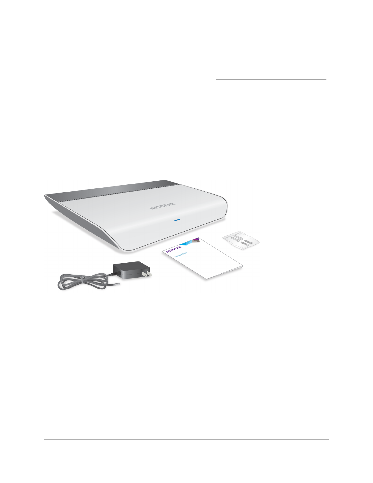
Switch Package Contents
The package contains the switch, AC power adapter (localized to the country of sale),
installation guide, wall-mount screws and anchors, and cable retention strap. (The strap
is not shown in the following figure).
Figure 1. Switch package contents
Switch
User Manual7Hardware Overview of the
Page 8
8-Port Gigabit Ethernet Smart Managed Plus Switch Model GS908E
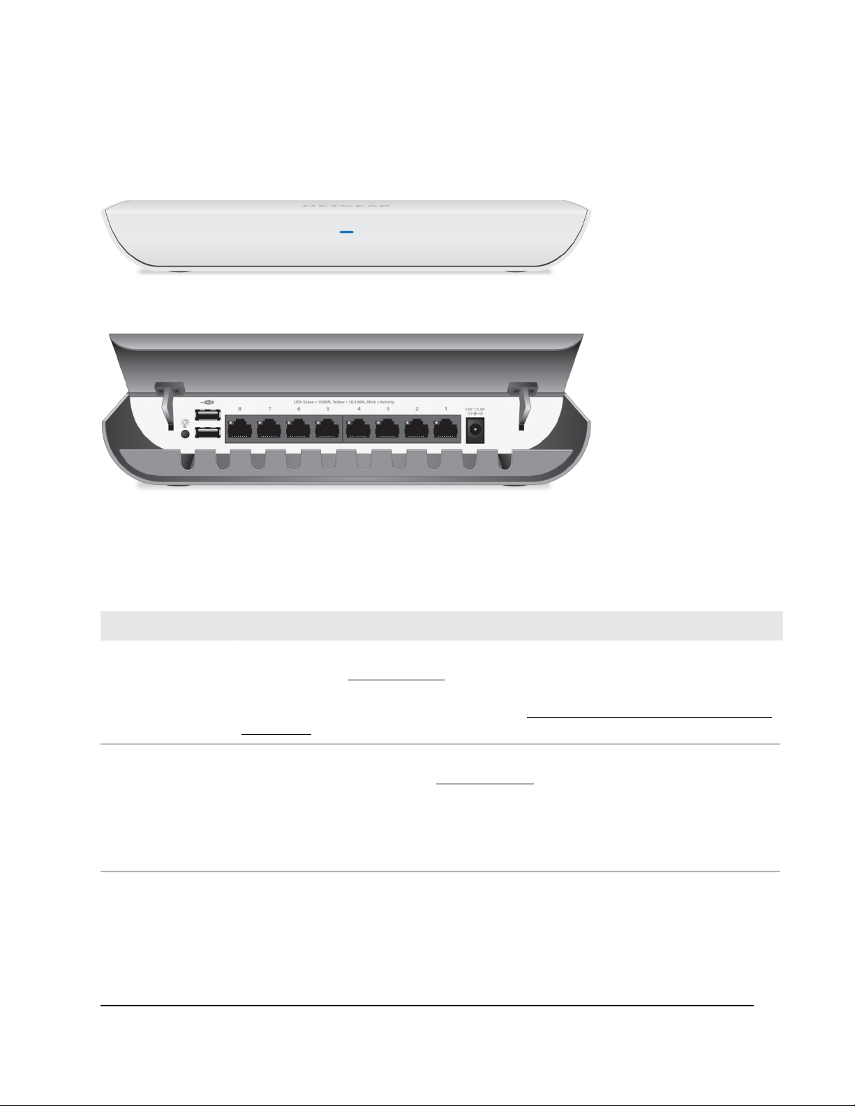
Status LEDs
Status LEDs are located on the front panel and back panel of the switch.
Figure 2. Power LED on the front panel
Figure 3. Port LEDs on the back panel
Table 1. LED descriptions
DescriptionLED
Power LED
Port LEDs
(1 through 8)
Off. No power is supplied to the switch or the switch functions in Stealth Mode with its Power
LED disabled (see Control the LEDs on page 78).
Solid blue. Power is supplied to the switch and the switch is ready for operation.
Solid amber. An event or a problem occurred (see Manage Auto-Diagnostics and Clear Events
or Problems on page 83).
Off. No link with a powered-on device is detected or the active ports function in Stealth Mode
with their port LEDs disabled (see Control the LEDs on page 78).
Solid green. A 1000M link with a powered-on device is detected.
Blinking green. Traffic is detected on the 1000M link.
Solid yellow. A 10M or 100M link with a powered-on device is detected.
Blinking yellow. Traffic is detected on the 10M or 100M link.
Switch
User Manual8Hardware Overview of the
Page 9
8-Port Gigabit Ethernet Smart Managed Plus Switch Model GS908E
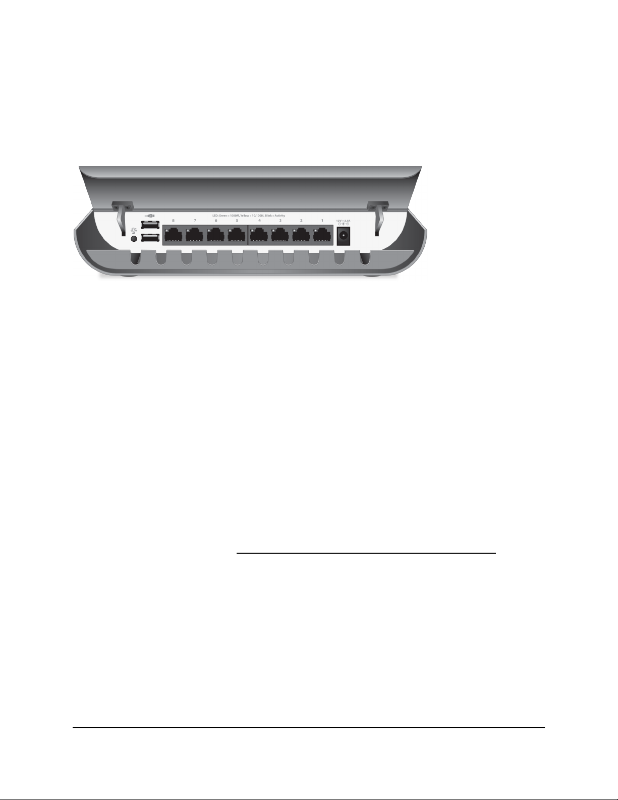
Back Panel
The back panel of the switch provides a LED button, two USB charging ports, eight
Ethernet ports, and a DC power connector.
Figure 4. Back panel with cover open
Viewed from left to right, the back panel contains the following components:
LED button. One button to turn the Power LED and port LEDs on and off.
•
USB charging ports. Two USB 2.0 ports for charging USB devices. Each port can
•
provider a maximum of 10W.
Note: Do not use these USB ports to connect storage or network devices. The USB
ports are intended for charging only.
Gigabit Ethernet ports 8 through 1. Eight Gigabit Ethernet RJ-45 LAN ports.
•
DC power connector. One 12V, 2.5A DC connector for the power adapter.
•
Note: The Reset button is located on the bottom panel of the switch. Press the
Reset button for more than five seconds to reset the switch to factory default settings.
For more information, see Return the Switch to Its Factory Default Settings on page
74.
Switch
User Manual9Hardware Overview of the
Page 10
8-Port Gigabit Ethernet Smart Managed Plus Switch Model GS908E
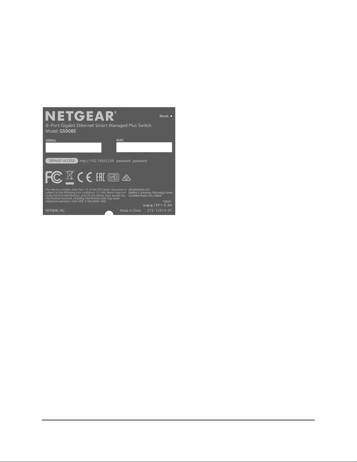
Switch Label
The switch label on the bottom panel of the switch shows the serial number, MAC
address, default login information, and other information for the switch. The label also
shows the location of the Reset button.
Figure 5. Switch label
Safety Instructions and Warnings
Use the following safety guidelines to ensure your own personal safety and to help
protect your system from potential damage.
To reduce the risk of bodily injury, electrical shock, fire, and damage to the equipment,
observe the following precautions:
This product is designed for indoor use only in a temperature-controlled (32–104°F
•
or 0–40°C) and humidity-controlled (90 percent maximum relative humidity,
noncondensing) environment.
Any device that is located outdoors and connected to this product must be properly
grounded and surge protected.
To the extent permissible by applicable law, failure to follow these guidelines can
result in damage to your NETGEAR product, which might not be covered by
NETGEAR’s warranty.
Switch
User Manual10Hardware Overview of the
Page 11

8-Port Gigabit Ethernet Smart Managed Plus Switch Model GS908E
Observe and follow service markings:
•
- Do not service any product except as explained in your system documentation.
- Opening or removing covers that are marked with the triangular symbol with a
lightning bolt can expose you to electrical shock. We recommend that only a
trained technician services components inside these compartments.
If any of the following conditions occur, unplug the product from the electrical outlet
•
and replace the part or contact your trained service provider:
- The power cable, extension cable, or plug is damaged.
-
An object fell into the product.
- The product was exposed to water.
- The product was dropped or damaged.
-
The product does not operate correctly when you follow the operating
instructions.
Keep your system away from radiators and heat sources.
•
Do not spill food or liquids on your system components, and never operate the
•
product in a wet environment. If the system gets wet, see the appropriate section in
your troubleshooting guide, or contact your trained service provider.
Do not push any objects into the openings of your system. Doing so can cause fire
•
or electric shock by shorting out interior components.
Use the product only with approved equipment.
•
Operate the product only from the type of external power source indicated on the
•
electrical ratings label. If you are not sure of the type of power source required,
consult your service provider or local power company.
To avoid damaging your system, be sure that the voltage selection switch (if provided)
•
on the power supply is set to match the power at your location:
-
115V, 60 Hz in most of North and South America and some Far Eastern countries
such as South Korea and Taiwan
- 100V, 50 Hz in eastern Japan and 100V, 60 Hz in western Japan
-
230V, 50 Hz in most of Europe, the Middle East, and the Far East
Be sure that attached devices are electrically rated to operate with the power available
•
in your location.
Use only the supplied DC power adapter. If you were not provided with a DC power
•
adapter, contact your reseller.
User Manual11Hardware Overview of the
Switch
Page 12

8-Port Gigabit Ethernet Smart Managed Plus Switch Model GS908E
To help prevent electric shock, plug the system and peripheral power cables into
•
properly grounded electrical outlets.
The peripheral power cables are equipped with three-prong plugs to help ensure
•
proper grounding. Do not use adapter plugs or remove the grounding prong from
a cable. If you must use an extension cable, use a three-wire cable with properly
grounded plugs.
Observe extension cable and power strip ratings. Make sure that the total ampere
•
rating of all products plugged into the extension cable or power strip does not
exceed 80 percent of the ampere ratings limit for the extension cable or power strip.
To help protect your system from sudden, transient increases and decreases in
•
electrical power, use a surge suppressor, line conditioner, or uninterruptible power
supply (UPS).
Position system cables and power cables carefully. Route cables so that they cannot
•
be stepped on or tripped over. Be sure that nothing rests on any cables.
Do not modify power cables or plugs. Consult a licensed electrician or your power
•
company for site modifications.
Always follow your local and national wiring rules.
•
Switch
User Manual12Hardware Overview of the
Page 13

2
Install and Access the Switch in Your Network
This chapter describes how to install and access the switch in your network.
The chapter contains the following sections:
• Set Up the Switch in Your Network and Power On the Switch
• Methods to Discover and Access the Switch
• Access the Switch and Discover the IP Address of the Switch
• Use the NETGEAR Insight App to Access the Switch
• Use the NETGEAR ProSAFE Plus Utility to Discover the Switch
• Change the Language of the Local Browser Interface
• Change the Switch Password
• Register the Switch
13
Page 14
8-Port Gigabit Ethernet Smart Managed Plus Switch Model GS908E
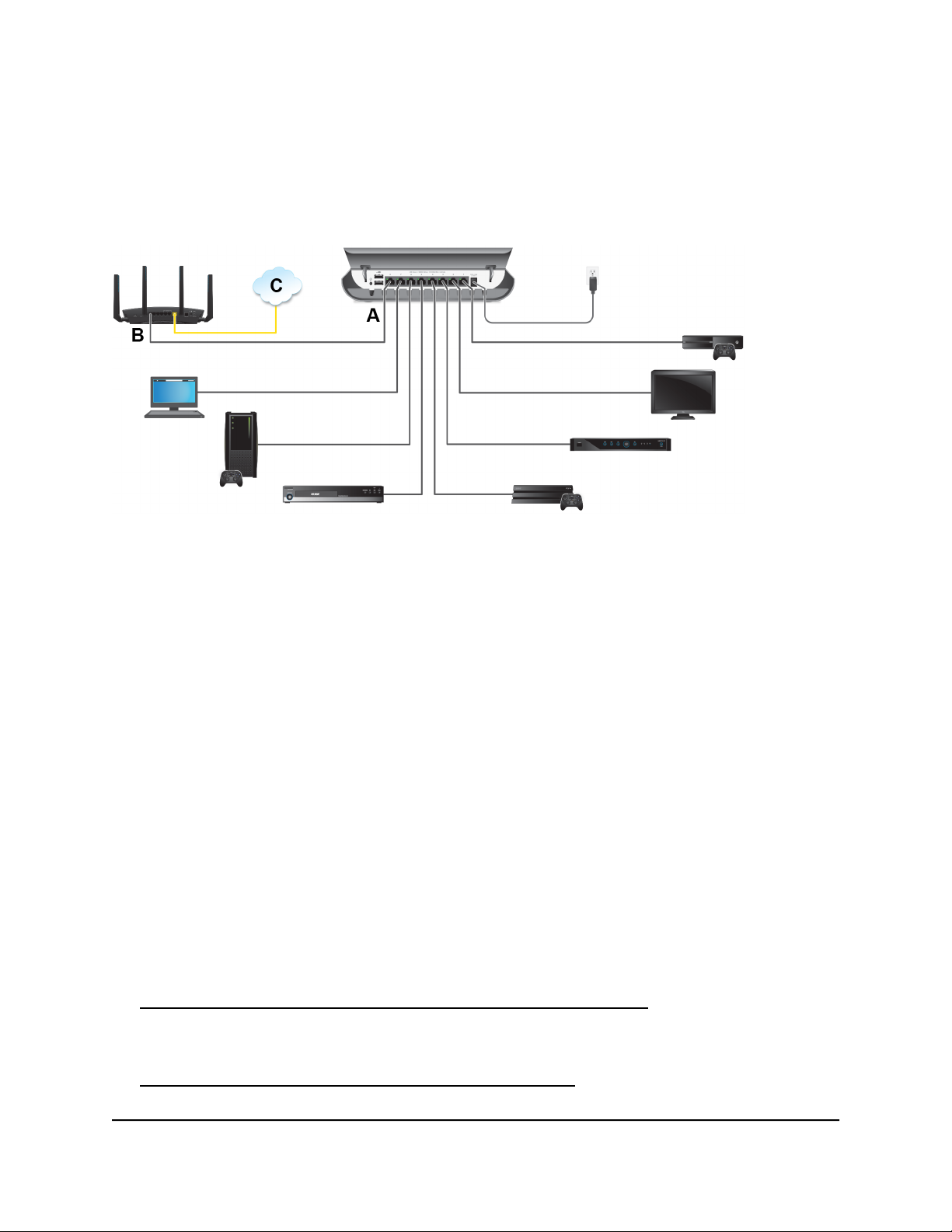
Set Up the Switch in Your Network and Power On the Switch
Figure 6. Sample connections
To set up the switch in your network and power on the switch:
1. Connect one port (A) on the switch to a LAN port (B) on a router that is connected
to the Internet (C).
2. Connect your devices to the other LAN ports on the switch.
3. Turn on the switch by connecting the power adapter to the switch and plugging the
power adapter into an electrical outlet.
The blue Power LED on the front of the switch lights and the port LEDs for connected
devices light.
Methods to Discover and Access the Switch
You can use any of the following methods to discover the switch in your network and
access the switch to configure and manage it:
Computer and web browser. Use a computer and a web browser to discover the
•
switch in your network and access the local browser interface of the switch (see
Access the Switch and Discover the IP Address of the Switch on page 15).
Insight app. Install the NETGEAR Insight app on a smartphone or tablet to discover
•
the switch in your network and access the local browser interface of the switch (see
Use the NETGEAR Insight App to Access the Switch on page 22).
User Manual14Install and Access the Switch in
Your Network
Page 15

8-Port Gigabit Ethernet Smart Managed Plus Switch Model GS908E
ProSAFE Plus Utility. Install the NETGEAR ProSAFE®Plus Utility on a Windows-based
•
computer and use the utility to discover the switch in your network (see Use the
NETGEAR ProSAFE Plus Utility to Discover the Switch on page 23). You cannot
perform basic configurations using the ProSAFE Plus Utility. That is, you can only
discover the switch in your network. To configure the switch, use the local browser
interface of switch.
Access the Switch and Discover the IP Address of the Switch
By default, the switch receives an IP address from a DHCP server (or a router that
functions as a DHCP server) in your network.
For information about setting up a fixed (static) IP address on the switch, see Set Up a
Fixed IP Address for the Switch on page 18.
Access the Switch From a Windows-Based Computer
To access the switch from a Windows-based computer and discover the switch IP
address:
1. Open Windows Explorer or File Explorer.
2.
Click the Network link.
3.
If prompted, enable the Network Discovery feature.
4.
Under Network Infrastructure, locate the GS908E switch.
5.
Double-click GS908E (xx:xx:xx:xx:xx:xx), in which xx:xx:xx:xx:xx:xx is the MAC
address of the switch.
The login page of the local browser interface opens.
6. Enter the switch password.
The default password is password. The password is case-sensitive.
The HOME page displays.
The right pane (or, depending on the size of your browser window, the middle pane)
shows the IP address that is assigned to the switch.
Your Network
User Manual15Install and Access the Switch in
Page 16

8-Port Gigabit Ethernet Smart Managed Plus Switch Model GS908E
Tip: You can copy and paste the IP address into a new shortcut or bookmark it for
quick access on your computer or mobile device. However, if you restart the switch,
a dynamic IP address (assigned by a DHCP server) might change and the bookmark
might no longer link to the login page for the switch. In that situation, you must
repeat this procedure so that you can discover the new IP address of the switch in
the network and update your bookmark accordingly. You can also set up a fixed
(static) IP address for the switch (see Set Up a Fixed IP Address for the Switch on
page 18) to make sure that the new bookmark always links to the login page for the
switch, even after you restart the switch.
Access the Switch From a Mac Using Bonjour
If your Mac supports Bonjour, you can use the following procedure. If your Mac does
not support Bonjour, see Access the Switch From a Mac or Windows-Based Computer
Using the NETGEAR Switch Discovery Tool on page 17.
To access the switch from a Mac using Bonjour and discover the switch IP address:
1.
Open the Safari browser.
2.
Select Safari > Preferences.
The General page displays.
3.
Click the Advanced tab.
The Advanced page displays.
4.
Select the Include Bonjour in the Bookmarks Menu check box.
5. Close the Advanced page.
6.
Depending on your Mac OS version, select one of the following, in which
xx:xx:xx:xx:xx:xx is the MAC address of the switch:
Bookmarks > Bonjour > GS908E (xx:xx:xx:xx:xx:xx)
•
Bookmarks > Bonjour > Webpages GS908E (xx:xx:xx:xx:xx:xx)
•
The login page of the local browser interface opens.
7. Enter the switch password.
The default password is password. The password is case-sensitive.
The HOME page displays.
The right pane (or, depending on the size of your browser window, the middle pane)
shows the IP address that is assigned to the switch.
User Manual16Install and Access the Switch in
Your Network
Page 17

8-Port Gigabit Ethernet Smart Managed Plus Switch Model GS908E
Tip: You can copy and paste the IP address into a new shortcut or bookmark it for
quick access on your computer or mobile device. However, if you restart the switch,
a dynamic IP address (assigned by a DHCP server) might change and the bookmark
might no longer link to the login page for the switch. In that situation, you must
repeat this procedure so that you can discover the new IP address of the switch in
the network and update your bookmark accordingly. You can also set up a fixed
(static) IP address for the switch (see Set Up a Fixed IP Address for the Switch on
page 18) to make sure that the new bookmark always links to the login page for the
switch, even after you restart the switch.
Access the Switch From a Mac or Windows-Based Computer Using the NETGEAR Switch Discovery Tool
The NETGEAR Switch Discovery Tool lets you discover the switch in your network and
access the local browser interface of the switch from a Mac or a 64-bit Windows-based
computer. If your Mac does not support Bonjour, use the following procedure.
To install the NETGEAR Switch Discovery Tool, discover the switch in your network,
access the switch, and discover the switch IP address:
1. Download the Switch Discovery Tool by visiting
netgear.com/support/product/netgear-switch-discovery-tool.aspx.
Depending on the computer that you are using, download either the Mac version
or the version for a 64-bit Windows-based computer.
2.
Temporarily disable the firewall, Internet security, antivirus programs, or all of these
on the computer that you use to configure the switch.
3.
Unzip the Switch Discovery Tool files, double-click the Setup.exe file (for example,
NetgearSDT-V1.1.115_Win_x64_Setup.exe), and install the program on your computer.
Depending on your computer setup, the installation process might add the NETGEAR
Switch Discovery Tool icon to the Dock of your Mac or the desktop of your
Windows-based computer.
4. Reenable the security services on your computer.
5. Power on the switch.
The DHCP server assigns the switch an IP address.
6. Connect your computer to the same network as the switch.
You can use a WiFi or wired connection. The computer and the switch must be on
the same Layer 2 network.
7. Open the Switch Discovery Tool.
User Manual17Install and Access the Switch in
Your Network
Page 18

8-Port Gigabit Ethernet Smart Managed Plus Switch Model GS908E
If the NETGEAR Switch Discovery Tool icon is in the Dock of your Mac or on the
desktop of your Windows-based computer, click or double-click the NETGEAR
Switch Discovery Tool icon to open the program.
The initial page displays a menu and a button.
8.
From the Choose a connection menu, select the network connection that allows
the Switch Discovery Tool to access the switch.
9.
Click the Start Searching button.
The Switch Discovery Tool displays a list of Smart Managed Plus Switches that it
discovers on the selected network.
For each switch, the tool displays the IP address.
10.
To access the local browser interface of the switch, click the ADMIN PAGE button.
The login page of the local browser interface opens.
11. Enter the switch password.
The default password is password. The password is case-sensitive.
The HOME page displays.
The right pane (or, depending on the size of your browser window, the middle pane)
shows the IP address that is assigned to the switch.
Tip: You can copy and paste the IP address into a new shortcut or bookmark it for
quick access on your computer or mobile device. However, if you restart the switch,
a dynamic IP address (assigned by a DHCP server) might change and the bookmark
might no longer link to the login page for the switch. In that situation, you must
repeat this procedure so that you can discover the new IP address of the switch in
the network and update your bookmark accordingly. You can also set up a fixed
(static) IP address for the switch (see Set Up a Fixed IP Address for the Switch on
page 18) to make sure that the new bookmark always links to the login page for the
switch, even after you restart the switch.
Set Up a Fixed IP Address for the Switch
By default, the switch receives an IP address from a DHCP server (or a router that
functions as a DHCP server) in your network. However, the DHCP server might not always
issue the same IP address to the switch. For easy access to the switch local browser
interface, you can set up a fixed (static) IP address on the switch. This allows you to
Your Network
User Manual18Install and Access the Switch in
Page 19

8-Port Gigabit Ethernet Smart Managed Plus Switch Model GS908E
manage the switch anytime from a mobile device because the switch IP address remains
the same.
To change the IP address of the switch, you can connect to the switch by one of the
following methods:
Through a network connection. If the switch and your computer are connected to
•
the same network (which is the most likely situation), you can change the IP address
of the switch through a network connection (see Set Up a Fixed IP Address for the
Switch Through a Network Connection on page 19).
Through a direct connection. In the unlikely situation that the switch is not connected
•
to a network, or for some reason you cannot connect to the switch over a network
connection, you can change the IP address of the switch by using an Ethernet cable
and making a direct connection to the switch (see Set Up a Fixed IP Address for the
Switch by Connecting Directly to the Switch Off-Network on page 20).
Set Up a Fixed IP Address for the Switch Through a Network Connection
If the switch and your computer are connected to the same network (which is the most
the likely situation), you can change the IP address of the switch through a network
connection.
To disable the DHCP client of the switch and change the IP address of the switch
to a fixed IP address by using a network connection:
1.
Open a web browser from a computer that is connected to the same network as the
switch.
2. Enter the IP address that is assigned to the switch.
The login page displays.
3. Enter the switch password.
The default password is password. The password is case-sensitive.
The HOME page displays.
4.
Select IP Address (DHCP On).
The button in the DHCP section displays blue because the DHCP client of the switch
is enabled.
5. Click the button in the DHCP section.
The button displays white, indicating that the DHCP client of the switch is disabled,
and the IP address fields become editable.
6.
Enter the fixed (static) IP address that you want to assign to the switch and the
associated subnet mask and gateway IP address.
Your Network
User Manual19Install and Access the Switch in
Page 20

8-Port Gigabit Ethernet Smart Managed Plus Switch Model GS908E
You can also either leave the address in the IP Address field as it is (with the IP
address that was issued by the DHCP server) or change the last three digits of the
IP address to an unused IP address.
7.
Write down the complete fixed IP address.
You can bookmark it later.
8.
Click the APPLY button.
Your settings are saved. Your switch web session is disconnected when you change
the IP address.
9.
If the login page does not display, in the address field of your web browser, enter
the new IP address of the switch.
The login page displays.
10.
For easy access to the local browser interface, bookmark the page on your computer.
Set Up a Fixed IP Address for the Switch by Connecting Directly to the Switch Off-Network
In the unlikely situation that the switch is not connected to a network, or for some reason
you cannot connect to the switch over a network connection, you can change the IP
address of the switch by using an Ethernet cable and making a direct connection to the
switch.
To disable the DHCP client of the switch and change the IP address of the switch
to a fixed IP address by using a direct connection:
1.
Connect an Ethernet cable from your computer to an Ethernet port on the switch.
2.
Change the IP address of your computer to be in the same subnet as the default IP
address of the switch.
The default IP address of the switch is 192.168.0.239. This means that you must
change the IP address of the computer to be on the same subnet as the default IP
address of the switch (192.168.0.x).
The method to change the IP address on your computer depends on the operating
system of your computer.
3.
Open a web browser from a computer that is connected to the switch directly through
an Ethernet cable.
4.
Enter 192.168.0.239 as the IP address of the switch.
The login page displays.
5. Enter the switch password.
The default password is password. The password is case-sensitive.
Your Network
User Manual20Install and Access the Switch in
Page 21

8-Port Gigabit Ethernet Smart Managed Plus Switch Model GS908E
The HOME page displays.
6.
Select IP Address (Default).
The button in the DHCP section displays blue because the DHCP client of the switch
is enabled.
7. Click the button in the DHCP section.
The button displays white, indicating that the DHCP client of the switch is disabled,
and the IP address fields become editable.
8.
Enter the fixed (static) IP address that you want to assign to the switch and the
associated subnet mask and gateway IP address.
9.
Write down the complete fixed IP address.
You can bookmark it later.
10.
Click the APPLY button.
Your settings are saved. Your switch web session is disconnected when you change
the IP address.
11.
Disconnect the switch from your computer and install the switch in your network.
For more information, see Set Up the Switch in Your Network and Power On the
Switch on page 14.
12. Restore your computer to its original IP address.
13.
Verify that you can connect to the switch with its new IP address:
a.
Open a web browser from a computer that is connected to the same network as
the switch.
b. Enter the new IP address that you assigned to the switch.
The login page displays.
c. Enter the switch password.
The default password is password. The password is case-sensitive.
The HOME page displays.
Your Network
User Manual21Install and Access the Switch in
Page 22

8-Port Gigabit Ethernet Smart Managed Plus Switch Model GS908E
Use the NETGEAR Insight App to Access the Switch
The NETGEAR Insight app lets you discover the switch in your network and access the
local browser interface of the switch from your smartphone or tablet.
To access the switch from the Insight app:
1.
On your iOS or Android mobile device, go to the app store, search for NETGEAR
Insight, and download and install the app.
2.
If the switch is directly connected to a WiFi router or access point, connect your
mobile device to the WiFi network of the router or access point.
3.
Select LOG IN to log in to your existing NETGEAR account or tap the CREATE
NETGEAR ACCOUNT button to create a new account.
4.
After you log in to your account, name your network and specify a device admin
password that applies to all devices that you add to this network, and tap the NEXT
button.
5.
You can now add a device. Choose one of the following options:
Add a device by scanning your network.
•
Add a device by entering its serial number.
•
Add a device by scanning its barcode.
•
Note: Pages might display and suggest that you connect the switch to power and
to an uplink. If you already did this, on these pages, tap the NEXT button.
6.
If the switch is not yet connected to the same WiFi network as your mobile device,
connect it now to the same WiFi network, wait two minutes, and then tap the NEXT
button.
The switch is discovered and registered on the network.
7.
In the Insight app, select the switch and tap the Visit Web Interface link.
The login page of the local browser interface opens.
8. Enter the switch password.
The default password is password. The password is case-sensitive.
The HOME page displays.
Your Network
User Manual22Install and Access the Switch in
Page 23

8-Port Gigabit Ethernet Smart Managed Plus Switch Model GS908E
Use the NETGEAR ProSAFE Plus Utility to Discover the Switch
For easiest access, we recommend that you cable the switch to a network with a router
or DHCP server that assigns IP addresses, power on the switch, and then use a computer
that is connected to the same network as the switch.
The NETGEAR ProSAFE Plus Utility runs on Windows-based computers and lets you
discover the switch in your network, after which you can access the local browser interface
of the switch.
Note: The ProSAFE Plus Utility requires WinPcap and Adobe Air. If WinPcap and Adobe
Air are not detected during the ProSAFE Plus Utility installation, you are prompted to
allow them to be installed.
To install the ProSAFE Plus Utility, use the utility to discover the switch in your
network, and access the local browser interface of the switch:
1. Download the ProSAFE Plus Utility by visiting netgear.com/support/product/PCU.
You must use ProSAFE Plus Utility version 2.5.3 or a later version.
2.
Temporarily disable the firewall, Internet security, antivirus programs, or all of these
on the computer that you use to configure the switch.
Note: Instead of disabling security services, you can also configure your computer’s
security software to allow broadcast UDP packets to go through UDP remote and
source (local and destination) ports 63321 through 63324. To allow this traffic, you
can create a rule in your computer’s security software.
3.
Unzip the ProSAFE Plus Utility files, double-click the .exe file (for example, ProSAFE
Plus Utility 2.5.3.exe), and install the program on your computer.
The installation process places a ProSAFE Plus Utility icon on your desktop.
4.
If you temporarily disabled any security services, reenable those services.
Note: We recommend that you restart your computer after installing the ProSAFE
Plus Utility.
5. Power on the switch.
The DHCP server assigns the switch an IP address.
6. Connect your computer to the same network as the switch.
Your Network
User Manual23Install and Access the Switch in
Page 24

8-Port Gigabit Ethernet Smart Managed Plus Switch Model GS908E
You can use a WiFi or wired connection. The computer and the switch must be on
the same Layer 2 network.
7.
Open the ProSAFE Plus Utility by double-clicking the ProSAFE Plus Utility icon on
your desktop.
The discovery process initiates and completes automatically and the configuration
home page displays a list of Smart Managed Plus Switches that the utility discovers
on the local network.
For each switch, the utility displays the IP address.
8. Open a web browser.
9. Enter the IP address that is assigned to the switch.
The login page displays.
10. Enter the switch password.
The default password is password. The password is case-sensitive.
The HOME page displays.
Change the Language of the Local Browser Interface
By default, the language of the local browser interface is set to Auto so that the switch
can automatically detect the language. However, you can set the language to a specific
one.
To change the language of the local browser interface:
1.
Open a web browser from a computer that is connected to the same network as the
switch or to the switch directly through an Ethernet cable.
2. Enter the IP address that is assigned to the switch.
The login page displays.
3. Enter the switch password.
The default password is password. The password is case-sensitive.
The HOME page displays.
4.
Select System Info.
The System Info fields display.
5.
From the Language menu, select a language.
Your Network
User Manual24Install and Access the Switch in
Page 25

8-Port Gigabit Ethernet Smart Managed Plus Switch Model GS908E
6.
Click the APPLY button.
A pop-up warning window opens.
7.
Click the CONTINUE button.
Your settings are saved and the language changes.
Change the Switch Password
The default password to access the local browser interface of the switch is password.
We recommend that you change this password to a more secure password. The ideal
password contains no dictionary words from any language and contains uppercase and
lowercase letters, numbers, and symbols. It can be up to 20 characters.
To change the switch password:
1.
Open a web browser from a computer that is connected to the same network as the
switch or to the switch directly through an Ethernet cable.
2. Enter the IP address that is assigned to the switch.
The login page displays.
3. Enter the switch password.
The default password is password. The password is case-sensitive.
The HOME page displays.
4.
From the menu at the top of the page, select ADVANCED SETTINGS.
The PRESET MODES page displays.
5.
From the menu on the left, select CHANGE PASSWORD.
The CHANGE PASSWORD page displays.
6.
In the Current Password field, type the current password for the switch.
7.
Type the new password in the New Password field and in the Retype New Password
field.
8.
Click the APPLY button.
Your settings are saved. Keep the new password in a secure location so that you can
access the switch in the future.
User Manual25Install and Access the Switch in
Your Network
Page 26

8-Port Gigabit Ethernet Smart Managed Plus Switch Model GS908E
Register the Switch
Registering the switch allows you to receive email alerts and streamlines the technical
support process. For you to register the switch, the switch must be connected to the
Internet.
To register the switch:
1.
Open a web browser from a computer that is connected to the same network as the
switch or to the switch directly through an Ethernet cable.
2. Enter the IP address that is assigned to the switch.
The login page displays.
3. Enter the switch password.
The default password is password. The password is case-sensitive.
The HOME page displays.
4.
From the menu at the top of the page, select ADVANCED SETTINGS.
The PRESET MODES page displays.
5.
From the menu on the left, select PRODUCT REGISTRATION.
The PRODUCT REGISTRATION page displays.
6.
Click the REGISTER button.
The switch contacts the registration server.
7. Follow the onscreen process to register the switch.
Your Network
User Manual26Install and Access the Switch in
Page 27

3
Optimize the Switch Performance
This chapter describes how you can optimize the performance of the switch.
The chapter contains the following sections:
• Manually Set the Quality of Service Mode and Port Rate Limits
• Manage Broadcast Filtering and Set Port Storm Control Rate Limits
• Manage Custom Performance Preset Modes
• Manage Individual Port Settings
27
Page 28

8-Port Gigabit Ethernet Smart Managed Plus Switch Model GS908E
Manually Set the Quality of Service Mode and Port Rate Limits
Instead of using preset performance modes, you can manually set the Quality of Service
(QoS) modes to manage traffic:
Port-based QoS mode. Lets you set the priority (low, medium, high, or critical) for
•
individual port numbers and lets you set rate limits for incoming and outgoing traffic
for individual ports. If broadcast filtering is enabled, you can also set the storm control
rate for incoming traffic for individual ports.
802.1P/DSCP QoS mode. Applies pass-through prioritization that is based on
•
tagged packets and lets you set rate limits for incoming and outgoing traffic for
individual ports. If broadcast filtering is enabled, you can also set the storm control
rate for incoming traffic for individual ports.
This QoS mode applies only to devices that support 802.1P and Differentiated
Services Code Point (DSCP) tagging. For devices that do not support 802.1P and
DSCP tagging, ports are not prioritized but the configured rate limit is still applied.
You can limit the rate of incoming traffic, outgoing traffic, or both on a port to prevent
the port (and the device that is attached to it) from taking up too much bandwidth on
the switch. Rate limiting, which you can set for individual ports in either QoS mode,
simply means that the switch slows down all traffic on a port so that traffic does not
exceed the limit that you set for that port. If you set the rate limit on a port too low, you
might, for example, see degraded video stream quality, sluggish response times during
online activity, and other problems.
Use Port-Based Quality of Service and Set Port Priorities
Port-based priority is the default QoS mode on the switch.
Note: If the QoS mode on the switch is 802.1P/DSCP, we recommend that you first
save your current QoS settings as a custom preset mode before you change the QoS
mode to the Port-based mode. For more information, see Save Your Quality of Service
Settings as a Custom Preset Mode on page 33.
For each port, you can set the priority and the rate limits for both incoming and outgoing
traffic:
Port priority. The switch services traffic from ports with a critical priority before traffic
•
from ports with a high, medium, or low priority. Similarly, the switch services traffic
from ports with a high priority before traffic from ports with a medium or low priority.
If severe network congestion occurs, the switch might drop packets with a low priority.
User Manual28Optimize the Switch
Performance
Page 29

8-Port Gigabit Ethernet Smart Managed Plus Switch Model GS908E
Port rate limits. The switch accepts traffic on a port at the rate (the speed of the
•
data transfer) that you set for incoming traffic on that port. The switch transmits traffic
from a port at the rate that you set for outgoing traffic on that port. You can select
each rate limit as a predefined data transfer threshold from 512 Kbps to 512 Mbps.
Note: If you set a port rate limit, the actual rate might fluctuate, depending on the type
of traffic that the port is processing.
To use the Port-based QoS mode and set the priority and rate limits for ports:
1.
Open a web browser from a computer that is connected to the same network as the
switch or to the switch directly through an Ethernet cable.
2. Enter the IP address that is assigned to the switch.
The login page displays.
3. Enter the switch password.
The default password is password. The password is case-sensitive.
The HOME page displays.
4.
From the menu at the top of the page, select SWITCHING.
The Quality of Service (QoS) page displays.
5.
If the selection from the QoS Mode menu is 802.1P/DSCP, do the following to
change the selection to Port-based:
a.
From the QoS Mode menu, select Port-based.
A pop-up warning window opens.
b.
Click the CONTINUE button.
The pop-up window closes.
Note: For information about broadcast filtering, see Manage Broadcast Filtering
and Set Port Storm Control Rate Limits on page 31.
6.
To set the port priorities, do the following:
a.
Click the PRIORITY tab.
b.
Click the blue pencil icon.
The EDIT PRIORITY page displays.
c.
For each port for which you want to set the priority, select Low, Medium, High,
or Critical from the individual menu for the port.
The default selection is High.
d.
Click the APPLY button.
Performance
User Manual29Optimize the Switch
Page 30

8-Port Gigabit Ethernet Smart Managed Plus Switch Model GS908E
Your settings are saved and the EDIT PRIORITY page closes.
7.
To set rate limits, do the following:
a.
Click the RATE LIMITS tab.
b.
Click the blue pencil icon.
The EDIT RATE LIMITS page displays.
c.
For each port for which you want to set rate limits, select the rate in Kbps or Mbps
from the individual In Limits and Out Limits menus for the port.
The default selection is No Limit.
d.
Click the APPLY button.
Your settings are saved and the EDIT RATE LIMITS page closes.
Use 802.1P/DSCP Quality of Service
In the 802.1P/DSCP QoS mode, the switch uses the 802.1P or DSCP information in the
header of an incoming packet to prioritize the packet. With this type of QoS, you cannot
control the port prioritization on the switch because the device that sends the traffic
(that is, the packets) to the switch prioritizes the traffic. However, you can set the rate
limits for individual ports on the switch.
The switch accepts traffic on a port at the rate (the speed of the data transfer) that you
set for incoming traffic on that port. The switch transmits traffic from a port at the rate
that you set for outgoing traffic on that port. You can select each rate limit as a predefined
data transfer threshold from 512 Kbps to 512 Mbps.
Note: If the QoS mode on the switch is Port-based, we recommend that you first save
your current QoS settings as a custom preset mode before you change the QoS mode
to the 802.1P/DSCP QoS mode. For more information, see Save Your Quality of Service
Settings as a Custom Preset Mode on page 33.
To use 802.1P/DSCP QoS mode and set the rate limits for ports:
1.
Open a web browser from a computer that is connected to the same network as the
switch or to the switch directly through an Ethernet cable.
2. Enter the IP address that is assigned to the switch.
The login page displays.
3. Enter the switch password.
The default password is password. The password is case-sensitive.
The HOME page displays.
Performance
User Manual30Optimize the Switch
Page 31

8-Port Gigabit Ethernet Smart Managed Plus Switch Model GS908E
4.
From the menu at the top of the page, select SWITCHING.
The Quality of Service (QoS) page displays.
5.
If the selection from the QoS Mode menu is Port-based, do the following to change
the selection to 802.1P/DSCP:
a.
From the QoS Mode menu, select 802.1P/DSCP.
A pop-up warning window opens.
b.
Click the CONTINUE button.
The pop-up window closes.
Note: For information about broadcast filtering, see Manage Broadcast Filtering
and Set Port Storm Control Rate Limits on page 31.
6.
To set rate limits, do the following:
a.
Click the RATE LIMITS tab.
If broadcast filtering is disabled, only the RATE LIMITS tab displays.
b.
Click the blue pencil icon.
The EDIT RATE LIMITS page displays.
c.
For each port for which you want to set rate limits, select the rate in Kbps or Mbps
from the individual In Limits and Out Limits menus for the port.
The default selection is No Limit.
d.
Click the APPLY button.
Your settings are saved and the EDIT RATE LIMITS page closes.
Manage Broadcast Filtering and Set Port Storm Control Rate Limits
A broadcast storm is a massive transmission of broadcast packets that are forwarded
to every port on the switch. If they are not blocked, broadcast storm packets can delay
or halt the transmission of other data and cause problems. However, you can block
broadcast storms on the switch.
You can also set storm control rate limits for each port. Storm control measures the
incoming broadcast, multicast, and unknown unicast frame rates separately on each
port, and discards the frames if the rate that you set for the port is exceeded. By default,
no storm control rate limit is set for a port. You can select each storm control rate limit
as a predefined data transfer threshold from 512 Kbps to 512 Mbps.
Performance
User Manual31Optimize the Switch
Page 32

8-Port Gigabit Ethernet Smart Managed Plus Switch Model GS908E
To manage broadcast filtering and set the storm control rate limits for ports:
1.
Open a web browser from a computer that is connected to the same network as the
switch or to the switch directly through an Ethernet cable.
2. Enter the IP address that is assigned to the switch.
The login page displays.
3. Enter the switch password.
The default password is password. The password is case-sensitive.
The HOME page displays.
4.
From the menu at the top of the page, select SWITCHING.
The Quality of Service (QoS) page displays.
5.
If the selection from the QoS Mode menu is not the QoS mode that you want to
configure, do the following to change the QoS mode:
a.
From the QoS Mode menu, select Port-Based or 802.1P/DSCP.
A pop-up warning window opens.
b.
Click the CONTINUE button.
The pop-up window closes and the QoS mode is changed.
6.
Click Broadcast Filtering button.
7.
Click the APPLY button.
Broadcast filtering is enabled. The STORM CONTROL RATE tab displays.
8.
To set storm control rate limits, do the following:
a.
Click the STORM CONTROL RATE tab.
b.
Click the blue pencil icon.
The EDIT STORM CONTROL RATE page displays.
c.
For each port for which you want to set storm control rate limits, select the rate
in Kbps or Mbps from the individual menu for the port.
The default selection is No Limit.
d.
Click the APPLY button.
Your settings are saved and the EDIT STORM CONTROL RATE page closes.
Performance
User Manual32Optimize the Switch
Page 33

8-Port Gigabit Ethernet Smart Managed Plus Switch Model GS908E
Manage Custom Performance Preset Modes
You can save your current Quality of Service (QoS) settings as a custom preset mode,
including the settings for IGMP snooping, flow control, the power saving mode, the
QoS mode, rate limiting, and the priorities of the individual ports.
The switch lets you save two custom preset modes. You can also rename or delete these
custom preset modes.
Save Your Quality of Service Settings as a Custom Preset Mode
You can save your current Quality of Service (QoS) settings as a custom preset mode
that you can reapply later.
To save your QoS settings as a custom preset mode:
1.
Open a web browser from a computer that is connected to the same network as the
switch or to the switch directly through an Ethernet cable.
2. Enter the IP address that is assigned to the switch.
The login page displays.
3. Enter the switch password.
The default password is password. The password is case-sensitive.
The HOME page displays.
4.
From the menu at the top of the page, select ADVANCED SETTINGS.
The PRESET MODES page displays. The LOAD tab is automatically selected.
5.
Click the SAVE tab.
The SAVE PRESET MODES page displays.
6.
In the Preset Mode Name field, enter a name from 1 to 16 characters for the custom
preset mode.
7.
Select the Slot 1 or 2 button.
You can save two custom preset modes, one in each slot.
8.
Click the APPLY button.
Your settings are saved. The preset custom mode is displayed on the PRESET MODES
page.
User Manual33Optimize the Switch
Performance
Page 34

8-Port Gigabit Ethernet Smart Managed Plus Switch Model GS908E
Apply a Custom Preset Mode
If you previously saved QoS, port prioritization, multicast, flow control, IGMP snooping,
and rate limiting settings as a custom preset mode (see Save Your Quality of Service
Settings as a Custom Preset Mode on page 33), you can apply the preset mode.
To apply a previously saved custom preset mode:
1.
Open a web browser from a computer that is connected to the same network as the
switch or to the switch directly through an Ethernet cable.
2. Enter the IP address that is assigned to the switch.
The login page displays.
3. Enter the switch password.
The default password is password. The password is case-sensitive.
The HOME page displays.
4.
From the menu at the top of the page, select ADVANCED SETTINGS.
The PRESET MODES page displays. The LOAD tab is automatically selected.
5. Select a custom preset mode.
The PREVIEW section shows the settings for the custom preset mode.
6.
Click the APPLY button.
Your settings are saved.
Apply the Standard Preset Mode
The Standard Preset mode, which is the default mode, gives all ports equal priority.
Applying the Standard Preset mode does the following:
Sets the QoS port priority for all ports to High (for more information, see Set the
•
Priority for a Port on page 38).
Enables IGMP snooping for the switch (for more information, see Manage IGMP
•
Snooping on page 61).
Disables flow control for all ports (for more information, Manage Flow Control for a
•
Port on page 39).
Disables power saving for the switch (for more information, see Manage the Power
•
Saving Mode on page 77).
Sets the QoS mode to Port-based (for more information, see Use Port-Based Quality
•
of Service and Set Port Priorities on page 28).
User Manual34Optimize the Switch
Performance
Page 35

8-Port Gigabit Ethernet Smart Managed Plus Switch Model GS908E
Disables rate limiting for all ports (for more information, see Set Rate Limits for a Port
•
on page 37).
Before you apply the Standard Preset mode, you can save your current QoS, port
prioritization, multicast, flow control, and IGMP snooping settings and other settings as
a custom preset mode (see Save Your Quality of Service Settings as a Custom Preset
Mode on page 33) so that you can easily revert to your current QoS configuration.
To apply the Standard Preset mode:
1.
Open a web browser from a computer that is connected to the same network as the
switch or to the switch directly through an Ethernet cable.
2. Enter the IP address that is assigned to the switch.
The login page displays.
3. Enter the switch password.
The default password is password. The password is case-sensitive.
The HOME page displays.
4.
From the menu at the top of the page, select ADVANCED SETTINGS.
The PRESET MODES page displays. The LOAD tab is automatically selected.
5.
Select STANDARD PRESET (DEFAULT).
The PREVIEW section shows the settings for the Standard Preset mode.
6.
Click the APPLY button.
Your settings are saved.
Rename a Custom Preset Mode
After you save a custom preset mode, you can rename the mode.
To rename a custom preset mode:
1.
Open a web browser from a computer that is connected to the same network as the
switch or to the switch directly through an Ethernet cable.
2. Enter the IP address that is assigned to the switch.
The login page displays.
3. Enter the switch password.
The default password is password. The password is case-sensitive.
The HOME page displays.
4.
From the menu at the top of the page, select ADVANCED SETTINGS.
Performance
User Manual35Optimize the Switch
Page 36

8-Port Gigabit Ethernet Smart Managed Plus Switch Model GS908E
The PRESET MODES page displays. The LOAD tab is automatically selected.
5.
Click the SAVE tab.
6.
Select the Slot 1 or 2 button.
7.
In the Preset Mode Name field, enter a new name from 1 to 16 characters for the
custom preset mode.
8.
Click the RENAME button.
Your settings are saved.
Delete a Custom Preset Mode
You can delete a custom preset mode that you no longer need. You cannot delete the
default Standard Preset mode.
To delete a custom preset mode:
1.
Open a web browser from a computer that is connected to the same network as the
switch or to the switch directly through an Ethernet cable.
2. Enter the IP address that is assigned to the switch.
The login page displays.
3. Enter the switch password.
The default password is password. The password is case-sensitive.
The HOME page displays.
4.
From the menu at the top of the page, select ADVANCED SETTINGS.
The PRESET MODES page displays. The LOAD tab is automatically selected.
5. Select a custom preset mode.
The PREVIEW section shows the settings for the custom preset mode.
6.
Click the DELETE button.
Your settings are saved. The custom preset mode is removed from the PRESET
MODES page.
Performance
User Manual36Optimize the Switch
Page 37

8-Port Gigabit Ethernet Smart Managed Plus Switch Model GS908E
Manage Individual Port Settings
For each individual port, you can set the port priority, set rate limits for incoming and
outgoing traffic, set the port speed (by default, the speed is set automatically), enable
flow control, and change the port name label.
Set Rate Limits for a Port
You can limit the rate of incoming (ingress) traffic, outgoing (egress) traffic, or both on
a port to prevent the port (and the device that is attached to it) from taking up too much
bandwidth on the switch. Rate limiting simply means that the switch slows down all
traffic on a port so that traffic does not exceed the limit that you set for that port. If you
set the rate limit on a port too low, you might, for example, see degraded video stream
quality, sluggish response times during online activity, and other problems.
You also can set port rate limits (the same feature) as part of the Quality of Service
configuration on the switch (see Manually Set the Quality of Service Mode and Port Rate
Limits on page 28).
To set rate limits for incoming and outgoing traffic on a port:
1.
Open a web browser from a computer that is connected to the same network as the
switch or to the switch directly through an Ethernet cable.
2. Enter the IP address that is assigned to the switch.
The login page displays.
3. Enter the switch password.
The default password is password. The password is case-sensitive.
The HOME page displays.
The PORT STATUS pane displays on the right or the bottom of the HOME page,
depending on the size of your browser window.
A port that is in use shows as UP. A port that is not in use shows as AVAILABLE.
4. Select the port.
The pane displays detailed information about the port.
5.
Click the EDIT button.
The EDIT PORT page displays for the selected port.
If the QoS mode on the switch is Port-based (the default setting), the Priority menu
displays on the page. If the QoS mode is 802.1P/DSCP, the Priority menu does not
display.
User Manual37Optimize the Switch
Performance
Page 38

8-Port Gigabit Ethernet Smart Managed Plus Switch Model GS908E
6.
From the In Rate Limit menu, Out Rate Limit menu, or both, select the rate in Kbps
or Mbps.
The default selection is No Limit.
7.
Click the APPLY button.
Your settings are saved.
Set the Priority for a Port
If the QoS mode on the switch is Port-based (the default setting), you can set the priority
for a port.
The switch services traffic from ports with a critical priority before traffic from ports with
a high, medium, or low priority. Similarly, the switch services traffic from ports with a
high priority before traffic from ports with a medium or low priority. If severe network
congestion occurs, the switch might drop packets with a low priority.
You also can set the priority for a port (the same feature) as part of the Quality of Service
configuration on the switch (see Use Port-Based Quality of Service and Set Port Priorities
on page 28.
To set the priority for a port:
1.
Open a web browser from a computer that is connected to the same network as the
switch or to the switch directly through an Ethernet cable.
2. Enter the IP address that is assigned to the switch.
The login page displays.
3. Enter the switch password.
The default password is password. The password is case-sensitive.
The HOME page displays.
The PORT STATUS pane displays on the right or the bottom of the HOME page,
depending on the size of your browser window.
A port that is in use shows as UP. A port that is not in use shows as AVAILABLE.
4. Select the port.
The pane displays detailed information about the port.
5.
Click the EDIT button.
The EDIT PORT page displays for the selected port.
If the QoS mode on the switch is Port-based (the default setting), the Priority menu
displays on the page. If the QoS mode is 802.1P/DSCP, the Priority menu does not
display.
User Manual38Optimize the Switch
Performance
Page 39

8-Port Gigabit Ethernet Smart Managed Plus Switch Model GS908E
6.
From the Priority menu, select Low, Medium, High, or Critical.
The default selection is High.
7.
Click the APPLY button.
Your settings are saved.
Manage Flow Control for a Port
IEEE 802.3x flow control works by pausing a port if the port becomes oversubscribed
(that is, the port receives more traffic than it can process) and dropping all traffic for
small bursts of time during the congestion condition.
You can enable or disable flow control for an individual port. By default, flow control is
disabled for all ports.
To manage flow control for a port:
1.
Open a web browser from a computer that is connected to the same network as the
switch or to the switch directly through an Ethernet cable.
2. Enter the IP address that is assigned to the switch.
The login page displays.
3. Enter the switch password.
The default password is password. The password is case-sensitive.
The HOME page displays.
The PORT STATUS pane displays on the right or the bottom of the HOME page,
depending on the size of your browser window.
A port that is in use shows as UP. A port that is not in use shows as AVAILABLE.
4. Select the port.
The pane displays detailed information about the port.
5.
Click the EDIT button.
The EDIT PORT page displays for the selected port.
If the QoS mode on the switch is Port-based (the default setting), the Priority menu
displays on the page. If the QoS mode is 802.1P/DSCP, the Priority menu does not
display.
6.
In the Flow Control section, enable or disable flow control by clicking the button.
When flow control is enabled, the button displays blue.
7.
Click the APPLY button.
User Manual39Optimize the Switch
Performance
Page 40

8-Port Gigabit Ethernet Smart Managed Plus Switch Model GS908E
Your settings are saved.
Change the Speed for a Port or Disable a Port
By default, the port speed on all ports is set automatically (that is, the setting is Auto)
after the switch determines the speed using autonegotiation with the linked device. We
recommend that you leave the Auto setting for the ports. However, you can select a
specific port speed setting for each port or disable a port by shutting it down manually.
To change the speed for a port or disable a port:
1.
Open a web browser from a computer that is connected to the same network as the
switch or to the switch directly through an Ethernet cable.
2. Enter the IP address that is assigned to the switch.
The login page displays.
3. Enter the switch password.
The default password is password. The password is case-sensitive.
The HOME page displays.
The PORT STATUS pane displays on the right or the bottom of the HOME page,
depending on the size of your browser window.
A port that is in use shows as UP. A port that is not in use shows as AVAILABLE.
4. Select the port.
The pane displays detailed information about the port.
5.
Click the EDIT button.
The EDIT PORT page displays for the selected port.
If the QoS mode on the switch is Port-based (the default setting), the Priority menu
displays on the page. If the QoS mode is 802.1P/DSCP, the Priority menu does not
display.
6.
Select one of the following options from the Speed menu:
Auto. The port speed is set automatically after the switch determines the speed
•
using autonegotiation with the linked device. This is the default setting.
Disable. The port is shut down (blocked).
•
10M half. The port is forced to function at 10 Mbps with half-duplex.
•
10M full. The port is forced to function at 10 Mbps with full-duplex.
•
100M half. The port is forced to function at 100 Mbps with half-duplex.
•
Performance
User Manual40Optimize the Switch
Page 41

8-Port Gigabit Ethernet Smart Managed Plus Switch Model GS908E
100M full. The port is forced to function at 100 Mbps with full-duplex.
•
Note: You cannot select Gigabit Ethernet as the port speed. However, if the setting
from the Speed menu is Auto, the switch can use autonegotiation to automatically
set the port speed to Gigabit Ethernet if the linked device supports that speed.
7.
Click the APPLY button.
Your settings are saved.
Add or Change the Name Label for a Port
By default, a port does not contain a port label. You can add or change the name label
for a port. Adding or changing a name label does not change the nature of a port, that
is, it is just a label.
To add or change a name label for a port:
1.
Open a web browser from a computer that is connected to the same network as the
switch or to the switch directly through an Ethernet cable.
2. Enter the IP address that is assigned to the switch.
The login page displays.
3. Enter the switch password.
The default password is password. The password is case-sensitive.
The HOME page displays.
The PORT STATUS pane displays on the right or the bottom of the HOME page,
depending on the size of your browser window.
A port that is in use shows as UP. A port that is not in use shows as AVAILABLE.
4. Select the port.
The pane displays detailed information about the port.
5.
Click the EDIT button.
The EDIT PORT page displays for the selected port.
If the QoS mode on the switch is Port-based (the default setting), the Priority menu
displays on the page. If the QoS mode is 802.1P/DSCP, the Priority menu does not
display.
6.
In the Port Name field, type a name label for the port.
The name label can be from 1 to 16 characters.
Performance
User Manual41Optimize the Switch
Page 42

8-Port Gigabit Ethernet Smart Managed Plus Switch Model GS908E
7.
Click the APPLY button.
Your settings are saved.
Performance
User Manual42Optimize the Switch
Page 43

4
Use VLANS for Traffic Segmentation
This chapter describes how you can use VLANs to segment traffic on the switch.
The chapter contains the following sections:
• VLAN Overview
• Manage Port-Based VLANs
• Manage 802.1Q-Based VLANs
• Deactivate the Port-Based or 802.1Q-Based VLAN Mode and Delete All VLANs
43
Page 44

8-Port Gigabit Ethernet Smart Managed Plus Switch Model GS908E
VLAN Overview
Virtual LANs (VLANs) are made up of networked devices that are grouped logically into
separate networks. You can group ports on a switch to create a virtual network made
up of the devices connected to the ports.
You can group ports in VLANs using either port-based or 802.1Q criteria:
Port-based VLANs. Assign ports to virtual networks. Ports with the same VLAN ID
•
are placed in the same VLAN. The number of VLANs is limited to the number of ports
on the switch.
This feature provides an easy way to partition a network into private subnetworks.
If the switch is the only switch in your network and you do not need a VLAN to function
across multiple network devices (such as a router, another switch, a WiFi AP, or any
network device that supports VLANs), we recommend that you use a port-based
VLAN.
802.1Q VLANs. Create virtual networks using the IEEE 802.1Q standard. 802.1Q
•
uses a VLAN tagging system to determine which VLAN an Ethernet frame belongs
to. To use an 802.1Q VLAN, you must know the VLAN ID.
In the 802.1Q VLAN configuration that is supported on the switch, VLAN 1 is added
to the switch and all ports (1 through 8) are untagged members of VLAN 1. You can
tag ports, untag ports, exclude ports, add more VLANs, assign a different VLAN to
a port, manage port PVIDs, and manage a voice VLAN.
When a port receives data that is untagged, the data is delivered normally. However,
when a port receives data that is tagged for a VLAN, the data is discarded unless
the port is a member of that VLAN. This technique is useful for communicating more
securely with devices outside your local network as well as receiving data from other
ports that are not in the VLAN.
The following table provides an overview of VLAN features that are supported on the
switch.
Table 2. Supported VLAN modes
802.1Q VLANPort-Based VLANVLAN Feature
Segmentation
648Total number of VLANs
YesNoEgress tagging
YesYesMultiple VLANs on a single port
YesNoVoice VLAN
User Manual44Use VLANS for Traffic
Page 45

8-Port Gigabit Ethernet Smart Managed Plus Switch Model GS908E
Manage Port-Based VLANs
After you activate the port-based VLAN mode, you can add and manage port-based
VLANs.
Activate the Port-Based VLAN Mode
By default, all types of VLANs are disabled on the switch. Before you can add and manage
port-based VLANs, you must activate the port-based VLAN mode.
When you activate the port-based VLAN mode, VLAN 1 is added to the switch and all
ports (1 through 8) are members of VLAN 1. This is the default VLAN in the port-based
VLAN mode.
To activate the port-based VLAN mode:
1.
Open a web browser from a computer that is connected to the same network as the
switch or to the switch directly through an Ethernet cable.
2. Enter the IP address that is assigned to the switch.
The login page displays.
3. Enter the switch password.
The default password is password. The password is case-sensitive.
The HOME page displays.
4.
From the menu at the top of the page, select SWITCHING.
The Quality of Service (QoS) page displays.
5.
From the menu on the left, select VLAN.
The VLAN page displays.
6.
In the Port-based VLAN (Basic Mode) section, click the ACTIVATE button.
A pop-up window opens, informing you that the current VLAN settings will be lost.
7.
Click the CONTINUE button.
Your settings are saved and the pop-up window closes. By default, VLAN 1 is added.
Create a Port-Based VLAN
A port-based VLAN configuration lets you assign ports on the switch to a VLAN. The
number of VLANs is limited to the number of ports on the switch. In a basic port-based
User Manual45Use VLANS for Traffic
Segmentation
Page 46

8-Port Gigabit Ethernet Smart Managed Plus Switch Model GS908E
VLAN configuration, ports with the same VLAN ID are placed into the same VLAN. One
port can be a member of multiple VLANs.
By default, all ports are members of VLAN 1.
To create a port-based VLAN:
1.
Open a web browser from a computer that is connected to the same network as the
switch or to the switch directly through an Ethernet cable.
2. Enter the IP address that is assigned to the switch.
The login page displays.
3. Enter the switch password.
The default password is password. The password is case-sensitive.
The HOME page displays.
4.
From the menu at the top of the page, select SWITCHING.
The Quality of Service (QoS) page displays.
5.
From the menu on the left, select VLAN.
The VLAN page displays.
If you did not yet activate the port-based VLAN mode, see Activate the Port-Based
VLAN Mode on page 45.
6.
In the Port-based VLAN section, click the ADD VLAN button.
7.
Specify the settings for the new VLAN:
VLAN Name. Enter a name from 1 to 20 characters.
•
VLAN ID. Enter a number from 1 to 8.
•
Ports. Select the ports that you want to include in the VLAN through a combination
•
of the following actions:
-
Click the Select All link to add all ports to the VLAN.
-
Click the Remove All link to remove all selected ports from the VLAN.
-
Click the icon for an unselected port to add the port to the VLAN.
-
Click the icon for a selected port to remove the port from the VLAN.
The icon for a selected port displays blue.
Note: If ports are members of the same LAG, you must assign them to the same
VLAN.
8.
Click the APPLY button.
User Manual46Use VLANS for Traffic
Segmentation
Page 47

8-Port Gigabit Ethernet Smart Managed Plus Switch Model GS908E
Your settings are saved. The new VLAN shows in the Port-based VLAN section.
Change a Port-Based VLAN
You can change the settings for an existing port-based VLAN.
To change a port-based VLAN:
1.
Open a web browser from a computer that is connected to the same network as the
switch or to the switch directly through an Ethernet cable.
2. Enter the IP address that is assigned to the switch.
The login page displays.
3. Enter the switch password.
The default password is password. The password is case-sensitive.
The HOME page displays.
4.
From the menu at the top of the page, select SWITCHING.
The Quality of Service (QoS) page displays.
5.
From the menu on the left, select VLAN.
The VLAN page displays.
6.
In the Port-based VLAN section, click the down arrow for the VLAN that you want to
change.
7.
Click the EDIT button.
8.
Change the settings for the VLAN:
VLAN Name. Enter a name from 1 to 20 characters.
•
VLAN ID. Enter a number from 1 to 8.
•
Ports. Select the ports that you want to include in the VLAN through a combination
•
of the following actions:
-
Click the Select All link to add all ports to the VLAN.
-
Click the Remove All link to remove all selected ports from the VLAN.
-
Click the icon for an unselected port to add the port to the VLAN.
-
Click the icon for a selected port to remove the port from the VLAN.
The icon for a selected port displays blue.
Note: If ports are members of the same LAG, you must assign them to the same
VLAN.
User Manual47Use VLANS for Traffic
Segmentation
Page 48

8-Port Gigabit Ethernet Smart Managed Plus Switch Model GS908E
9.
Click the APPLY button.
Your settings are saved. The modified VLAN shows in the Port-based VLAN section.
Delete a Port-Based VLAN
You can delete a port-based VLAN that you no longer need. You cannot delete the
default VLAN.
Note: If you deactivate the port-based VLAN mode, all port-based VLANs are deleted.
To delete a port-based VLAN:
1.
Open a web browser from a computer that is connected to the same network as the
switch or to the switch directly through an Ethernet cable.
2. Enter the IP address that is assigned to the switch.
The login page displays.
3. Enter the switch password.
The default password is password. The password is case-sensitive.
The HOME page displays.
4.
From the menu at the top of the page, select SWITCHING.
The Quality of Service (QoS) page displays.
5.
From the menu on the left, select VLAN.
The VLAN page displays.
6.
In the Port-based VLAN section, click the down arrow for the VLAN that you want to
delete.
7.
Click the DELETE button.
Your settings are saved. The VLAN is deleted.
Manage 802.1Q-Based VLANs
After you activate the 802.1Q-based VLAN mode (also referred to as the advanced
VLAN mode), you can add and manage 802.1Q-based VLANs, manage PVIDs, and set
the voice VLAN.
User Manual48Use VLANS for Traffic
Segmentation
Page 49

8-Port Gigabit Ethernet Smart Managed Plus Switch Model GS908E
Activate the 802.1Q-Based VLAN Mode
By default, all types of VLANs are disabled on the switch. Before you can add and manage
802.1Q-based VLANs, PVIDs, and voice VLAN, you must activate the 802.1Q-based
VLAN mode. This mode is also referred to as the advanced VLAN mode.
When you activate the 802.1Q-based VLAN mode, VLAN 1 is added to the switch and
all ports (1 through 8) are untagged members of VLAN 1. This is the default VLAN in
the 802.1Q-based VLAN mode.
To activate the 802.1Q-based VLAN mode:
1.
Open a web browser from a computer that is connected to the same network as the
switch or to the switch directly through an Ethernet cable.
2. Enter the IP address that is assigned to the switch.
The login page displays.
3. Enter the switch password.
The default password is password. The password is case-sensitive.
The HOME page displays.
4.
From the menu at the top of the page, select SWITCHING.
The Quality of Service (QoS) page displays.
5.
From the menu on the left, select VLAN.
The VLAN page displays.
6.
In the 802.1Q-based VLAN (Advanced Mode) section, click the ACTIVATE button.
A pop-up window opens, informing you that the current VLAN settings will be lost.
7.
Click the CONTINUE button.
Your settings are saved and the pop-up window closes. By default, VLAN 1 is added.
Create an 802.1Q-Based VLAN
An 802.1Q-based VLAN configuration lets you assign ports on the switch as tagged or
untagged members to a VLAN with an ID number in the range of 1–4094. By default,
all ports are untagged members of VLAN 1.
To create an 802.1Q-based VLAN:
1.
Open a web browser from a computer that is connected to the same network as the
switch or to the switch directly through an Ethernet cable.
2. Enter the IP address that is assigned to the switch.
User Manual49Use VLANS for Traffic
Segmentation
Page 50

8-Port Gigabit Ethernet Smart Managed Plus Switch Model GS908E
The login page displays.
3. Enter the switch password.
The default password is password. The password is case-sensitive.
The HOME page displays.
4.
From the menu at the top of the page, select SWITCHING.
The Quality of Service (QoS) page displays.
5.
From the menu on the left, select VLAN.
The VLAN page displays.
If you did not yet activate the 802.1Q-based VLAN mode, see Activate the
802.1Q-Based VLAN Mode on page 49.
6.
In the 802.1Q-based VLAN section, click the ADD VLAN button.
7.
Specify the settings for the new VLAN:
VLAN Name. Enter a name from 1 to 20 characters.
•
VLAN ID. Enter a number from 1 to 4094.
•
Ports. Select the ports that you want to include in the VLAN through a combination
•
of the following actions:
-
Click the TAG ALL button to add all ports as tagged ports to the VLAN.
-
Click the UNTAG ALL button to add all ports as untagged ports to the VLAN.
-
Click the EXCLUDE ALL button to exclude (remove) all ports from the VLAN.
-
Click the T button for a port to add the port as a tagged port to the VLAN.
-
Click the U button for a port to add the port as an untagged to port the VLAN.
-
Click the E button port to exclude (remove) the port from the VLAN.
For a selected port, the T button (for a tagged port) or U button (for an untagged
port) displays blue. For an unselected port, the E button (for an excluded port)
displays blue.
Note: If ports are members of the same LAG, you must assign them to the same
VLAN.
For information about setting the new VLAN as the voice VLAN, see Set an Existing
802.1Q-Based VLAN as the Voice VLAN and Adjust the CoS Value on page 54.
8.
Click the APPLY button.
Your settings are saved. The new VLAN shows in the 802.1Q-based VLAN section.
User Manual50Use VLANS for Traffic
Segmentation
Page 51

8-Port Gigabit Ethernet Smart Managed Plus Switch Model GS908E
Change an 802.1Q-Based VLAN
You can change the settings for an existing 802.1Q-based VLAN.
To change an 802.1Q-based VLAN:
1.
Open a web browser from a computer that is connected to the same network as the
switch or to the switch directly through an Ethernet cable.
2. Enter the IP address that is assigned to the switch.
The login page displays.
3. Enter the switch password.
The default password is password. The password is case-sensitive.
The HOME page displays.
4.
From the menu at the top of the page, select SWITCHING.
The Quality of Service (QoS) page displays.
5.
From the menu on the left, select VLAN.
The VLAN page displays.
6.
In the 802.1Q-based VLAN section, click the down arrow for the VLAN that you want
to change.
7.
Click the EDIT button.
8.
Change the settings for the VLAN:
VLAN Name. Enter a name from 1 to 20 characters.
•
VLAN ID. Enter a number from 1 to 4094.
•
Ports. Select the ports that you want to include in the VLAN through a combination
•
of the following actions:
-
Click the TAG ALL button to add all ports as tagged ports to the VLAN.
-
Click the UNTAG ALL button to add all ports as untagged ports to the VLAN.
-
Click the EXCLUDE ALL button to exclude (remove) all ports from the VLAN.
-
Click the T button for a port to add the port as a tagged port to the VLAN.
-
Click the U button for a port to add the port as an untagged to port the VLAN.
-
Click the E button port to exclude (remove) the port from the VLAN.
Segmentation
User Manual51Use VLANS for Traffic
Page 52

8-Port Gigabit Ethernet Smart Managed Plus Switch Model GS908E
For a selected port, the T button (for a tagged port) or U button (for an untagged
port) displays blue. For an unselected port, the E button (for an excluded port)
displays blue.
Note: If ports are members of the same LAG, you must assign them to the same
VLAN.
For information about setting the VLAN as the voice VLAN, see Set an Existing
802.1Q-Based VLAN as the Voice VLAN and Adjust the CoS Value on page 54.
9.
Click the APPLY button.
Your settings are saved. The modified VLAN shows in the 802.1Q-based VLAN
section.
Delete an 802.1Q-Based VLAN
You can delete an 802.1Q-based VLAN that you no longer need. You cannot delete the
default VLAN. You cannot delete a VLAN that is in use as the PVID for a port either. You
must first remove the VLAN as the PVID for the port before you can delete the VLAN.
Note: If you deactivate the 802.1Q-based VLAN mode, all port-based VLANs are
deleted.
To delete an 802.1Q-based VLAN:
1.
Open a web browser from a computer that is connected to the same network as the
switch or to the switch directly through an Ethernet cable.
2. Enter the IP address that is assigned to the switch.
The login page displays.
3. Enter the switch password.
The default password is password. The password is case-sensitive.
The HOME page displays.
4.
From the menu at the top of the page, select SWITCHING.
The Quality of Service (QoS) page displays.
5.
From the menu on the left, select VLAN.
The VLAN page displays.
6.
In the 802.1Q-based VLAN section, click the down arrow for the VLAN that you want
to delete.
User Manual52Use VLANS for Traffic
Segmentation
Page 53

8-Port Gigabit Ethernet Smart Managed Plus Switch Model GS908E
7.
Click the DELETE button.
Your settings are saved. The VLAN is deleted.
Specify a Port PVID for an 802.1Q-Based VLAN
A default port VLAN ID (PVID) is a VLAN ID tag that the switch assigns to incoming data
packets that are not already addressed (tagged) for a particular VLAN. For example, if
you connect a computer to port 6 of the switch and you want it to be a part of VLAN 2,
add port 6 as a member of VLAN 2 and configure port 6 to automatically add a PVID of
2 to all data that the switch receives from the computer. This step makes sure that the
data from the computer on port 6 can be seen only by other members of VLAN 2. You
can assign only one PVID to a port.
Note: If you did not yet create an 802.1Q-based VLAN, all ports are assigned PVID 1
and you cannot assign another PVID to a port. In this situation, first create a custom
802.1Q-based VLAN.
To assign a PVID to a port:
1.
Open a web browser from a computer that is connected to the same network as the
switch or to the switch directly through an Ethernet cable.
2. Enter the IP address that is assigned to the switch.
The login page displays.
3. Enter the switch password.
The default password is password. The password is case-sensitive.
The HOME page displays.
4.
From the menu at the top of the page, select SWITCHING.
The Quality of Service (QoS) page displays.
5.
From the menu on the left, select VLAN.
The VLAN page displays.
If you did not yet activate the 802.1Q-based VLAN mode, see Activate the
802.1Q-Based VLAN Mode on page 49.
6.
At the bottom of the 802.1Q-based VLAN, click the PVID Table link.
The Port and VLAN IDs section displays.
7.
Click the icon for a port.
The PVID menu displays.
Segmentation
User Manual53Use VLANS for Traffic
Page 54

8-Port Gigabit Ethernet Smart Managed Plus Switch Model GS908E
8.
From the PVID menu, select a VLAN ID and name.
9.
Click the APPLY button.
Your settings are saved. The Port and VLAN IDs section displays again. The VLAN
ID that is assigned as the PVID displays with an asterisk (*) next to the port.
10.
Click the BACK button.
The VLAN page displays.
Set an Existing 802.1Q-Based VLAN as the Voice VLAN and Adjust the CoS Value
The switch can support a single 802.1Q-based voice VLAN to facilitate voice over IP
(VoIP) traffic.
The default Class of Service (CoS) value for the voice VLAN is 6, which you can adjust
to any value from 0 (the lowest priority) to 7 (the highest priority). The voice VLAN CoS
value applies to all traffic on the voice VLAN. You can set the default VLAN (VLAN 1) as
the voice VLAN.
To set an existing 802.1Q-based VLAN as the voice VLAN and adjust the CoS value
for the voice VLAN:
1.
Open a web browser from a computer that is connected to the same network as the
switch or to the switch directly through an Ethernet cable.
2. Enter the IP address that is assigned to the switch.
The login page displays.
3. Enter the switch password.
The default password is password. The password is case-sensitive.
The HOME page displays.
4.
From the menu at the top of the page, select SWITCHING.
The Quality of Service (QoS) page displays.
5.
From the menu on the left, select VLAN.
The VLAN page displays.
If you did not yet activate the 802.1Q-based VLAN mode, see Activate the
802.1Q-Based VLAN Mode on page 49.
6.
In the 802.1Q-based VLAN section, click the down arrow for the VLAN that you want
to set as the voice VLAN.
7.
Click the EDIT button.
User Manual54Use VLANS for Traffic
Segmentation
Page 55

8-Port Gigabit Ethernet Smart Managed Plus Switch Model GS908E
8.
Under the Port section, click the Voice VLAN button.
If the voice VLAN is enabled, the button displays blue.
9.
From the Class of Service menu, select a CoS value.
A value of 0 is the lowest priority and a value of 7 is the highest priority.
For information about viewing and changing the OUI settings, see Change the OUI
Table for the Voice VLAN on page 55.
10.
Click the APPLY button.
Your settings are saved. The voice VLAN shows in the 802.1Q-based VLAN section
with a telephone icon.
Change the OUI Table for the Voice VLAN
For the voice VLAN, the switch supports default Organizationally Unique Identifiers
(OUIs), which are associated with VoIP phones of specific manufacturers. All traffic
received on voice VLAN ports from VoIP phones with a listed OUI is forwarded on the
voice VLAN.
You can add, change, and remove OUIs, including the default OUIs. The maximum
number of OUI entries in the table is 15. The first 3 bytes of the MAC address contain
a manufacturer identifier, while the last 3 bytes contain a unique station ID. You must
add an OUI prefix in the format AA:BB:CC.
You can add a new OUI, change an existing OUI, and delete an OUI that you no longer
need.
To change the OUI table for the voice VLAN:
1.
Open a web browser from a computer that is connected to the same network as the
switch or to the switch directly through an Ethernet cable.
2. Enter the IP address that is assigned to the switch.
The login page displays.
3. Enter the switch password.
The default password is password. The password is case-sensitive.
The HOME page displays.
4.
From the menu at the top of the page, select SWITCHING.
The Quality of Service (QoS) page displays.
5.
From the menu on the left, select VLAN.
The VLAN page displays.
Segmentation
User Manual55Use VLANS for Traffic
Page 56

8-Port Gigabit Ethernet Smart Managed Plus Switch Model GS908E
6.
In the 802.1Q-based VLAN section, click the down arrow for the voice VLAN.
The voice VLAN shows in the 802.1Q-based VLAN section with a telephone icon.
7.
Click the OUI Settings link.
The OUI table displays.
8.
To add a new OUI, do the following:
a.
Click the ADD OUI button.
The OUI Entry page displays.
b. Enter the new OUI and description.
c.
Click the SAVE button.
Your settings are saved.
9.
To change an existing OUI, do the following:
a. Click the down arrow next to the OUI that you want to change.
b.
Click the EDIT button.
c. Change the OUI, description, or both.
d.
Click the SAVE button.
Your settings are saved.
10.
To delete an OUI that you no longer need, do the following:
a. Click the down arrow next to the OUI that you want to delete.
b.
Click the DELETE button.
Your settings are saved and the OUI is deleted.
11.
Click the BACK button.
The VLAN page displays.
Segmentation
User Manual56Use VLANS for Traffic
Page 57

8-Port Gigabit Ethernet Smart Managed Plus Switch Model GS908E
Deactivate the Port-Based or 802.1Q-Based VLAN Mode and Delete All VLANs
If you activated the port-based VLAN mode or the 802.1Q-based VLAN mode, you can
deactivate either VLAN mode and delete all VLANs.
To deactivate the port-based VLAN mode or 802.1Q-based VLAN mode and delete
all VLANs:
1.
Open a web browser from a computer that is connected to the same network as the
switch or to the switch directly through an Ethernet cable.
2. Enter the IP address that is assigned to the switch.
The login page displays.
3. Enter the switch password.
The default password is password. The password is case-sensitive.
The HOME page displays.
4.
From the menu at the top of the page, select SWITCHING.
The Quality of Service (QoS) page displays.
5.
From the menu on the left, select VLAN.
The VLAN page displays.
6.
In the No VLANs section, click the ACTIVATE button.
A pop-up window opens, informing you that the current VLAN settings will be lost.
7.
Click the CONTINUE button.
Your settings are saved and the pop-up window closes.
Segmentation
User Manual57Use VLANS for Traffic
Page 58

5
Manage the Switch in Your Network
This chapter describes how you can manage the switch in your network.
The chapter contains the following sections:
• Manage Switch Discovery Protocols
• Manage Multicast
• Set Up Static Link Aggregation
• Change the IP Address of the Switch
• Reenable the DHCP Client of the Switch
58
Page 59

8-Port Gigabit Ethernet Smart Managed Plus Switch Model GS908E
Manage Switch Discovery Protocols
It is important to know the IP address of the switch so that you can access the local
browser interface of the switch. The switch supports Universal Plug and Play (UPnP),
Bonjour, and NETGEAR Switch Discovery Protocol (NSDP), which are protocols that can
discover the switch. A device that functions in the same network as the switch and that
supports one of these protocols can discover the switch and obtain the IP address.
As a security measure, you can disable one or more discovery protocols. However, we
recommend that you leave at least one discovery protocol enabled so that a device can
discover the switch if the switch IP address changes.
Manage Universal Plug and Play
A Windows-based device that supports Universal Plug and Play (UPnP) can discover the
switch in the network so that you can find the switch IP address and log in to the local
browser interface of the switch. UPnP is enabled by default. You can disable UPnP for
security reasons.
To manage UPnP:
1.
Open a web browser from a computer that is connected to the same network as the
switch or to the switch directly through an Ethernet cable.
2. Enter the IP address that is assigned to the switch.
The login page displays.
3. Enter the switch password.
The default password is password. The password is case-sensitive.
The HOME page displays.
4.
From the menu at the top of the page, select ADVANCED SETTINGS.
The PRESET MODES page displays.
5.
From the menu on the left, select SWITCH DISCOVERY.
The SWITCH DISCOVERY page displays.
6. Enable or disable UPnP by clicking the button in the UPnP section.
When UPnP is enabled, the button displays blue.
7.
Click the APPLY button.
Your settings are saved.
Network
User Manual59Manage the Switch in Your
Page 60

8-Port Gigabit Ethernet Smart Managed Plus Switch Model GS908E
Manage Bonjour
A Mac OS device that supports Bonjour can discover the switch in the network so that
you can find the switch IP address and log in to the local browser interface of the switch.
Bonjour is enabled by default. You can disable Bonjour for security reasons.
To manage Bonjour:
1.
Open a web browser from a computer that is connected to the same network as the
switch or to the switch directly through an Ethernet cable.
2. Enter the IP address that is assigned to the switch.
The login page displays.
3. Enter the switch password.
The default password is password. The password is case-sensitive.
The HOME page displays.
4.
From the menu at the top of the page, select ADVANCED SETTINGS.
The PRESET MODES page displays.
5.
From the menu on the left, select SWITCH DISCOVERY.
The SWITCH DISCOVERY page displays.
6. Enable or disable Bonjour by clicking the button in the Bonjour section.
When Bonjour is enabled, the button displays blue.
7.
Click the APPLY button.
Your settings are saved.
Manage NETGEAR Switch Discovery Protocol
A NETGEAR device or application that supports NETGEAR Switch Discovery Protocol
(NSDP) can discover the switch in the network so that you can find the switch IP address
and log in to the local browser interface of the switch. NSDP is enabled by default. You
can disable NSDP for security reasons.
To manage NSDP:
1.
Open a web browser from a computer that is connected to the same network as the
switch or to the switch directly through an Ethernet cable.
2. Enter the IP address that is assigned to the switch.
The login page displays.
3. Enter the switch password.
User Manual60Manage the Switch in Your
Network
Page 61

8-Port Gigabit Ethernet Smart Managed Plus Switch Model GS908E
The default password is password. The password is case-sensitive.
The HOME page displays.
4.
From the menu at the top of the page, select ADVANCED SETTINGS.
The PRESET MODES page displays.
5.
From the menu on the left, select SWITCH DISCOVERY.
The SWITCH DISCOVERY page displays.
6. Enable or disable NSDP by clicking the button in the NSDP section.
When NSDP is enabled, the button displays blue.
7.
Click the APPLY button.
Your settings are saved.
Manage Multicast
Multicast IP traffic is traffic that is destined to a host group. Host groups are identified
by Class D IP addresses, which range from 224.0.0.0 to 239.255.255.255. Internet Group
Management Protocol (IGMP) snooping allows the switch to forward multicast traffic
intelligently. Based on the IGMP query and report messages, the switch forwards traffic
only to the ports that request the multicast traffic rather than to all ports, which could
affect network performance.
IGMP snooping helps to optimize multicast performance and is especially useful for
bandwidth-intensive IP multicast applications such as online media streaming
applications.
Manage IGMP Snooping
Internet Group Management Protocol (IGMP) snooping is enabled by default. Under
some circumstances you might want to temporarily disable IGMP snooping.
To manage IGMP snooping:
1.
Open a web browser from a computer that is connected to the same network as the
switch or to the switch directly through an Ethernet cable.
2. Enter the IP address that is assigned to the switch.
The login page displays.
3. Enter the switch password.
The default password is password. The password is case-sensitive.
Network
User Manual61Manage the Switch in Your
Page 62

8-Port Gigabit Ethernet Smart Managed Plus Switch Model GS908E
The HOME page displays.
4.
From the menu at the top of the page, select SWITCHING.
The Quality of Service (QoS) page displays.
5.
From the menu on the left, select MULTICAST.
The MULTICAST page displays.
6. Enable or disable IGMP snooping by clicking the button in the IGMP Snooping
section.
When IGMP snooping is enabled, the button displays blue.
7.
Click the APPLY button.
Your settings are saved.
Enable a VLAN for IGMP Snooping
You can enable IGMP for a VLAN only if you enabled the port-based VLAN mode (see
Manage Port-Based VLANs on page 45) or the 802.1Q-based VLAN mode (see Manage
802.1Q-Based VLANs on page 48).
To enable IGMP snooping for a VLAN:
1.
Open a web browser from a computer that is connected to the same network as the
switch or to the switch directly through an Ethernet cable.
2. Enter the IP address that is assigned to the switch.
The login page displays.
3. Enter the switch password.
The default password is password. The password is case-sensitive.
The HOME page displays.
4.
From the menu at the top of the page, select SWITCHING.
The Quality of Service (QoS) page displays.
5.
From the menu on the left, select MULTICAST.
The MULTICAST page displays.
6.
In the VLAN ID Enabled for IGMP Snooping section, enter a VLAN ID in the field.
If you enabled either the port-based VLAN mode or the 802.1Q-based VLAN mode,
the default VLAN for IGMP snooping is VLAN 1.
7.
Click the APPLY button.
User Manual62Manage the Switch in Your
Network
Page 63

8-Port Gigabit Ethernet Smart Managed Plus Switch Model GS908E
Your settings are saved.
Manage Blocking of Unknown Multicast Addresses
As a way to limit unnecessary multicast traffic, you can block multicast traffic from
unknown multicast addresses. If you do this, the switch forwards multicast traffic only
to ports in the multicast group that the switch learned through IGMP snooping. By
default, multicast traffic from unknown addresses is allowed.
To manage blocking of unknown multicast addresses:
1.
Open a web browser from a computer that is connected to the same network as the
switch or to the switch directly through an Ethernet cable.
2. Enter the IP address that is assigned to the switch.
The login page displays.
3. Enter the switch password.
The default password is password. The password is case-sensitive.
The HOME page displays.
4.
From the menu at the top of the page, select SWITCHING.
The Quality of Service (QoS) page displays.
5.
From the menu on the left, select MULTICAST.
The MULTICAST page displays.
6.
Enable or disable the blocking of unknown multicast traffic by clicking the button in
the Block Unknown Multicast Address section.
When the blocking of unknown multicast traffic is enabled, the button displays blue.
7.
Click the APPLY button.
Your settings are saved.
Manage IGMPv3 IP Header Validation
You can enable IGMPv3 IP header validation so that the switch inspects whether IGMPv3
packets conform to the IGMPv3 standard. By default, IGMPv3 IP header validation is
disabled. If IGMPv3 IP header validation is enabled, IGMPv3 messages must include a
Network
User Manual63Manage the Switch in Your
Page 64

8-Port Gigabit Ethernet Smart Managed Plus Switch Model GS908E
time-to-live (TTL) value of 1 and a ToS byte of 0xC0 (Internetwork Control). In addition,
the router alert IP option (9404) must be set.
Note: If IGMPv3 IP header validation is enabled, switch does not drop IGMPv1 and
IGMPv2 traffic but processes this traffic normally.
To manage IGMPv3 IP header validation:
1.
Open a web browser from a computer that is connected to the same network as the
switch or to the switch directly through an Ethernet cable.
2. Enter the IP address that is assigned to the switch.
The login page displays.
3. Enter the switch password.
The default password is password. The password is case-sensitive.
The HOME page displays.
4.
From the menu at the top of the page, select SWITCHING.
The Quality of Service (QoS) page displays.
5.
From the menu on the left, select MULTICAST.
The MULTICAST page displays.
6. Enable or disable IGMPv3 IP header validation by clicking the button in the Validate
IGMPv3 IP Header section.
When IGMPv3 IP header validation is enabled, the button displays blue.
7.
Click the APPLY button.
Your settings are saved.
Set Up a Static Router Port for IGMP Snooping
If your network does not include a device that sends IGMP queries, the switch cannot
discover the router port dynamically. (The router port is a port on a device in the network
that performs IGMP snooping in the network.) In this situation, select one port on the
switch as the dedicated static router port for IGMP snooping, allowing all IGMP Join
and Leave messages in the network to be forwarded to this port.
To set up a static router port for IGMP snooping:
1.
Open a web browser from a computer that is connected to the same network as the
switch or to the switch directly through an Ethernet cable.
2. Enter the IP address that is assigned to the switch.
User Manual64Manage the Switch in Your
Network
Page 65

8-Port Gigabit Ethernet Smart Managed Plus Switch Model GS908E
The login page displays.
3. Enter the switch password.
The default password is password. The password is case-sensitive.
The HOME page displays.
4.
From the menu at the top of the page, select SWITCHING.
The Quality of Service (QoS) page displays.
5.
From the menu on the left, select MULTICAST.
The MULTICAST page displays.
6.
From the menu in the IGMP Snooping Static Router Port section, select a specific
port as the router port or select Any to let IGMP Join and Leave messages be sent
to every port on the switch.
Typically, the uplink port (that is, the port that is connected to your router or to the
device that provides your Internet connection) serves as the router port.
7.
Click the APPLY button.
Your settings are saved.
Set Up Static Link Aggregation
Static link aggregation on the switch allows you to combine multiple Ethernet ports into
a single logical link. Your network devices treat the aggregation as if it were a single
link. Depending on how link aggregation is set up in your network, the link supports
either increased bandwidth (a larger pipe) or fault tolerance (if one port fails, another
one takes over).
The switch supports two static LAGs with up to four ports each. That means that one
static LAG can support a link of up to 4 Gbps.
Note: The switch does not support Link Aggregation Control Protocol (LACP).
You set up static link aggregation on the switch through a link aggregation group (LAG)
in the following order:
1. Set up the LAG on the switch (see Set Up a Link Aggregation Group on page 66).
2.
Connect the ports that must be members of the LAG on the switch to the ports that
must be members of the LAG on another device in your network (see Make a Link
Aggregation Connection on page 67).
User Manual65Manage the Switch in Your
Network
Page 66

8-Port Gigabit Ethernet Smart Managed Plus Switch Model GS908E
3. Enable the LAG on the switch (see Enable a Link Aggregation Group on page 67)
and on the other device.
Set Up a Link Aggregation Group
You set up static link aggregation on the switch by adding up to four ports to a link
aggregation group (LAG) and by enabling the LAG. However, for a LAG to take effect,
you first must make sure that all ports that participate in the LAG (that is, the ports on
both devices) use the same speed, duplex mode, and flow control setting (see Manage
Individual Port Settings on page 37 for information about changing these settings on
the switch) and you must set up a physical link aggregation connection (see Make a Link
Aggregation Connection on page 67).
After you set up a link aggregation group and make a physical link aggregation
connection, you can enable the link aggregation group (see Enable a Link Aggregation
Group on page 67).
To set up one or more link aggregation groups on the switch:
1.
Open a web browser from a computer that is connected to the same network as the
switch or to the switch directly through an Ethernet cable.
2. Enter the IP address that is assigned to the switch.
The login page displays.
3. Enter the switch password.
The default password is password. The password is case-sensitive.
The HOME page displays.
4.
From the menu at the top of the page, select SWITCHING.
The Quality of Service (QoS) page displays.
5.
From the menu on the left, select LINK AGGREGATION.
The LINK AGGREGATION page displays.
6.
To add ports to LAG 1, click two, three, or all port icons from 1 to 4.
The icon for a selected port displays blue.
LAG 1 must consist of at least two ports but can consist of all ports in the range from
1 through 4.
7.
To add ports to LAG 2, click two, three, or all port icons from 5 to 8.
The icon for a selected port displays blue.
LAG 2 must consist of at least two ports but can consist of all ports in the range from
5 through 8.
User Manual66Manage the Switch in Your
Network
Page 67

8-Port Gigabit Ethernet Smart Managed Plus Switch Model GS908E
8.
Click the APPLY button.
Your settings are saved.
Make a Link Aggregation Connection
Before you make a physical link aggregation connection to another network device
(usually a router or another switch) that also supports link aggregation, you must first
set up a link aggregation group (LAG) on the switch (see Set Up a Link Aggregation
Group on page 66). If you do not, the LAG cannot take effect.
All ports that participate in a LAG (that is, the ports on both devices) must use the same
speed, full duplex mode, and flow control setting. For information about changing these
settings on the switch, see Manage Individual Port Settings on page 37.
To make link aggregation connections between the switch and another network
device:
Using Ethernet cables, connect each port that must be a member of the LAG on the
switch to each port that must be a member of the same LAG on another network
device.
LAG 1 can include ports 1 through 4. LAG 2 can include ports 5 through 8.
The port numbers on the other network device do not matter as long as the ports
on the other network device are members of the same LAG, the LAG consists of the
same total number of ports, and the ports use the same speed, full duplex mode,
and flow control setting as the ports in the LAG on the switch.
Enable a Link Aggregation Group
After you set up a link aggregation group (see Set Up a Link Aggregation Group on
page 66) and make a physical link aggregation connection (see Make a Link Aggregation
Connection on page 67), you can enable the link aggregation group.
Note: You must also enable the link aggregation group on the other network device.
To enable a link aggregation group on the switch:
1.
Open a web browser from a computer that is connected to the same network as the
switch or to the switch directly through an Ethernet cable.
2. Enter the IP address that is assigned to the switch.
The login page displays.
3. Enter the switch password.
The default password is password. The password is case-sensitive.
Network
User Manual67Manage the Switch in Your
Page 68

8-Port Gigabit Ethernet Smart Managed Plus Switch Model GS908E
The HOME page displays.
4.
From the menu at the top of the page, select SWITCHING.
The Quality of Service (QoS) page displays.
5.
From the menu on the left, select LINK AGGREGATION.
The LINK AGGREGATION page displays.
6.
Click the LAG 1 button, LAG 2 button, or both buttons.
The button for a LAG that is enabled displays blue.
7.
Click the APPLY button.
Your settings are saved.
Change the IP Address of the Switch
By default, the switch receives an IP address from a DHCP server (or a router that
functions as a DHCP server) in your network.
To disable the DHCP client of the switch and change the IP address of the switch
to a fixed IP address:
1.
Open a web browser from a computer that is connected to the same network as the
switch or to the switch directly through an Ethernet cable.
2. Enter the IP address that is assigned to the switch.
The login page displays.
3. Enter the switch password.
The default password is password. The password is case-sensitive.
The HOME page displays.
4.
Select IP Address (DHCP On).
The IP address fields display but you cannot change them yet. The button in the
DHCP section displays blue because the DHCP client of the switch is enabled.
5. Click the button in the DHCP section.
The button displays white, indicating that the DHCP client of the switch is disabled,
and you can now change the IP address fields.
6.
Enter the fixed (static) IP address that you want to assign to the switch and the
associated subnet mask and gateway IP address.
7.
Click the APPLY button.
Network
User Manual68Manage the Switch in Your
Page 69

8-Port Gigabit Ethernet Smart Managed Plus Switch Model GS908E
A pop-up window displays a message.
8.
Click the X in the pop-up window.
Your settings are saved. Your switch web session might be disconnected when you
change the IP address.
Reenable the DHCP Client of the Switch
If you disabled the DHCP client of the switch and changed the IP address of the switch
to a fixed (static) IP address, you can reverse the situation.
To reenable the DHCP client on the switch:
1.
Open a web browser from a computer that is connected to the same network as the
switch or to the switch directly through an Ethernet cable.
2. Enter the IP address that is assigned to the switch.
The login page displays.
3. Enter the switch password.
The default password is password. The password is case-sensitive.
The HOME page displays.
4.
Select IP Address (Fixed IP).
The IP address fields display. The button in the DHCP section displays white because
the DHCP client of the switch is disabled.
5. Click the button in the DHCP section.
The button displays blue, indicating that the DHCP client of the switch is enabled.
The IP address fields no longer display.
6.
Click the APPLY button.
A pop-up window displays a message.
7.
Click the X in the pop-up window.
Your settings are saved. The switch receives an IP address from a DHCP server (or
a router that functions as a DHCP server) in your network. Your switch web session
might be disconnected when you enable the DHCP client of the switch.
Network
User Manual69Manage the Switch in Your
Page 70

6
Maintain and Monitor the Switch
This chapter describes how you can maintain and monitor the switch.
The chapter contains the following sections:
• Manually Check for New Switch Firmware and Update the Switch
• Manage the Configuration File
• Return the Switch to Its Factory Default Settings
• Control Management Access to the Switch
• Change or Lift Access Restrictions to the Switch
• Manage the Power Saving Mode
• Control the LEDs
• Change the Switch Device Name
• View System Information
• View Switch Connections
• View the Status of a Port
• View the Port Statistics
70
Page 71

8-Port Gigabit Ethernet Smart Managed Plus Switch Model GS908E
Manually Check for New Switch Firmware and Update the Switch
You can manually check for the latest firmware version through the local browser interface
of the switch, download the firmware, and upload the firmware to the switch. If firmware
release notes are available with new firmware, read the release notes to find out if you
must reconfigure the switch after updating.
To manually check for new switch firmware and update the switch:
1.
Open a web browser from a computer that is connected to the same network as the
switch or to the switch directly through an Ethernet cable.
2. Enter the IP address that is assigned to the switch.
The login page displays.
3. Enter the switch password.
The default password is password. The password is case-sensitive.
The HOME page displays.
4.
From the menu at the top of the page, select ADVANCED SETTINGS.
The PRESET MODES page displays.
5.
From the menu on the left, select FIRMWARE.
The FIRMWARE page displays. The page also shows the UPDATE FIRMWARE section.
The displays the current firmware version of the switch.
6.
To check if new firmware is available, click the link in the FIRMWARE section.
A NETGEAR web page opens.
7.
If new firmware is available, download the firmware file to your computer.
If the file does not end in .bin or .image, you might need to unzip the file. For example,
if the file ends in .rar, you must unzip the file.
8.
In the FIRMWARE UPDATE section, click the blue file icon, navigate to the firmware
file that you just downloaded, and select the file.
An example of a firmware file name is GS908E_V1.0.0.2.bin.
9.
Click the UPDATE button.
A pop-up window displays a warning and the firmware update process starts.
User Manual71Maintain and Monitor the Switch
Page 72

8-Port Gigabit Ethernet Smart Managed Plus Switch Model GS908E
Warning: Do not interrupt the network connection or power to the switch during
the firmware update process. Do not disconnect any Ethernet cables or power off
the switch until the firmware update process and switch reboot are complete.
Your switch web session is disconnected and you must log back in to the local
browser interface.
Manage the Configuration File
The configuration settings of the switch are stored within the switch in a configuration
file. You can back up (save) this file to your computer or restore it from your computer
to the switch.
Back Up the Switch Configuration
You can save a copy of the current configuration settings. If necessary, you can restore
the configuration settings later.
To back up the configuration settings switch of the switch:
1.
Open a web browser from a computer that is connected to the same network as the
switch or to the switch directly through an Ethernet cable.
2. Enter the IP address that is assigned to the switch.
The login page displays.
3. Enter the switch password.
The default password is password. The password is case-sensitive.
The HOME page displays.
4.
From the menu at the top of the page, select ADVANCED SETTINGS.
The PRESET MODES page displays.
5.
From the menu on the left, select CONFIGURATION FILE.
The RESTORE CONFIGURATION page displays.
6.
Click the BACKUP tab.
The BACKUP CONFIGURATION page displays.
7.
Click the BACKUP button.
8.
Follow the directions of your browser to save the file.
The name of the backup file is GS908E.cfg.
User Manual72Maintain and Monitor the Switch
Page 73

8-Port Gigabit Ethernet Smart Managed Plus Switch Model GS908E
Restore the Switch Configuration
If you backed up the configuration file, you can restore the configuration from this file.
To restore the configuration settings of the switch:
1.
Open a web browser from a computer that is connected to the same network as the
switch or to the switch directly through an Ethernet cable.
2. Enter the IP address that is assigned to the switch.
The login page displays.
3. Enter the switch password.
The default password is password. The password is case-sensitive.
The HOME page displays.
4.
From the menu at the top of the page, select ADVANCED SETTINGS.
The PRESET MODES page displays.
5.
From the menu on the left, select CONFIGURATION FILE.
The RESTORE CONFIGURATION page displays.
6.
Click the blue file icon and navigate to and select the saved configuration file.
The name of the saved configuration file is GS908E.cfg.
The RESTORE button changes to the APPLY CONFIGURATION button.
7.
Click the APPLY CONFIGURATION button.
A pop-up window displays a warning.
8.
Click the CONTINUE button.
The configuration is uploaded to the switch.
Warning: Do not interrupt the network connection or power to the switch during
the restoration process. Do not disconnect any Ethernet cables or power off the
switch until the restoration process and switch reboot are complete.
Your switch web session is disconnected and you must log back in to the local
browser interface.
User Manual73Maintain and Monitor the Switch
Page 74

8-Port Gigabit Ethernet Smart Managed Plus Switch Model GS908E
Return the Switch to Its Factory Default Settings
Under some circumstances (for example, if you lost track of the changes that you made
to the switch settings or you move the switch to a different network), you might want to
erase the configuration and reset the switch to factory default settings.
To reset the switch to factory default settings, you can either use the Reset button on
the bottom of the switch or use the reset function in the local browser interface. However,
if you changed and lost the password and cannot access the switch, you must use the
Reset button.
After you reset the switch to factory default settings, the password is password and the
switch’s DHCP client is enabled. For more information, see Factory Default Settings on
page 90.
Use the Reset Button to Reset the Switch
You can use the Reset button to return the switch to its factory default settings.
Caution: This process erases all settings that you configured on the switch.
To reset the switch to factory default settings:
1.
On the bottom of the switch, locate the recessed Reset button.
2.
Using a straightened paper clip, press and hold the Reset button for more than five
seconds.
3.
Release the Reset button.
The configuration is reset to factory default settings. When the reset is complete,
the switch reboots. This process takes less than one minute.
Warning: Do not interrupt the network connection or power to the switch during
the reset process. Do not disconnect any Ethernet cables or power off the switch
until the reset process and switch reboot are complete.
User Manual74Maintain and Monitor the Switch
Page 75

8-Port Gigabit Ethernet Smart Managed Plus Switch Model GS908E
Use the Local Browser Interface to Reset the Switch
Caution: This process erases all settings that you configured on the switch.
To reset the switch to factory default settings using the local browser interface:
1.
Open a web browser from a computer that is connected to the same network as the
switch or to the switch directly through an Ethernet cable.
2. Enter the IP address that is assigned to the switch.
The login page displays.
3. Enter the switch password.
The default password is password. The password is case-sensitive.
The HOME page displays.
4.
From the menu at the top of the page, select ADVANCED SETTINGS.
The PRESET MODES page displays.
5.
From the menu on the left, select DEFAULT SETTINGS.
The DEFAULT SETTINGS page displays.
6.
Click the RESTORE DEFAULT SETTINGS button.
A warning pop-up window opens.
7.
Click the CONTINUE button.
The switch is reset to factory default settings and reboots.
Warning: Do not interrupt the network connection or power to the switch during
the reset process. Do not disconnect any Ethernet cables or power off the switch
until the reset process and switch reboot are complete.
Control Management Access to the Switch
You can control which IP address or IP addresses can access the switch through the
local browser interface for management purposes.
To control management access to the switch:
1.
Open a web browser from a computer that is connected to the same network as the
switch or to the switch directly through an Ethernet cable.
2. Enter the IP address that is assigned to the switch.
User Manual75Maintain and Monitor the Switch
Page 76

8-Port Gigabit Ethernet Smart Managed Plus Switch Model GS908E
The login page displays.
3. Enter the switch password.
The default password is password. The password is case-sensitive.
The HOME page displays.
4.
From the menu at the top of the page, select ADVANCED SETTINGS.
The PRESET MODES page displays.
5.
From the menu on the left, select ACCESS CONTROL.
The ACCESS CONTROL page displays.
6.
Click the ADD button.
7.
Specify the IP address or IP addresses:
IP Address. Enter a single IP address or a network IP address.
•
Enter a network IP address in the format x.x.x.0, for example, 192.168.100.0.
Mask. If you enter a single IP address, enter 255.255.255.255 as the mask. If
•
you enter a network IP address, enter 255.255.255.0 as the mask.
8.
Click the APPLY button.
Your settings are saved.
9. To enter more IP addresses, repeat the previous three steps.
Change or Lift Access Restrictions to the Switch
If you set up IP addresses that are allowed to access the switch through the local browser
interface for management purposes, you can remove one or more IP addresses, or you
can remove all IP addresses and in that way lift access restrictions.
If you lift access restrictions, any IP address can access the local browser interface of
the switch. (The user still must enter a password to access the local browser interface.)
To change or lift access restrictions to the switch:
1.
Open a web browser from a computer that is connected to the same network as the
switch or to the switch directly through an Ethernet cable.
2. Enter the IP address that is assigned to the switch.
The login page displays.
User Manual76Maintain and Monitor the Switch
Page 77

8-Port Gigabit Ethernet Smart Managed Plus Switch Model GS908E
3. Enter the switch password.
The default password is password. The password is case-sensitive.
The HOME page displays.
4.
From the menu at the top of the page, select ADVANCED SETTINGS.
The PRESET MODES page displays.
5.
From the menu on the left, select ACCESS CONTROL.
The ACCESS CONTROL page displays.
6. Click the IP address that you want to remove.
The DELETE button displays.
7.
Click the DELETE button.
The IP address is removed and can no longer access the local browser interface of
the switch.
8. To remove more IP addresses, repeat the previous step.
If you remove all IP addresses, all access restrictions are lifted and any IP address
can access the local browser interface of the switch.
Manage the Power Saving Mode
The power saving mode enables the IEEE 802.3az Energy Efficient Ethernet (EEE)
function, cable length power saving, and link-up and link-down power saving:
IEEE 802.3az. Combines the Energy Efficient Ethernet (EEE) 802.3 MAC sublayer
•
with the 100BASE-TX, 1000BASE-T, and 10GBASE-T physical layers to support
operation in Low Power Idle (LPI) mode. When LPI mode is enabled, systems on
both sides of the link can disable portions of their functionality and save power during
periods of low link utilization.
Short cable power saving. Dynamically detects and adjusts power that is required
•
for the detected cable length.
Link-down power saving. Reduces the power consumption considerably when the
•
network cable is disconnected. When the network cable is reconnected, the switch
detects an incoming signal and restores normal power.
By default, the power saving mode is disabled.
User Manual77Maintain and Monitor the Switch
Page 78

8-Port Gigabit Ethernet Smart Managed Plus Switch Model GS908E
To manage the power saving mode on the switch:
1.
Open a web browser from a computer that is connected to the same network as the
switch or to the switch directly through an Ethernet cable.
2. Enter the IP address that is assigned to the switch.
The login page displays.
3. Enter the switch password.
The default password is password. The password is case-sensitive.
The HOME page displays.
4.
From the menu at the top of the page, to the right of NETGEAR, click the three-dot
icon and select Power Saving.
The POWER SAVING pop-up window opens.
5. Enable or disable the power saving mode by clicking the button.
When the power saving mode is enabled, the button displays blue.
(You do not need to click an APPLY button.)
Control the LEDs
You can turn the Power LED and port LEDs on the switch on and off, either by pushing
the LED button on the back of the switch to the left of the USB ports, or by using the
local browser interface. By default, a port LED lights when you connect a powered-on
device to the port. When the switch functions with its LEDs off, we refer to it as Stealth
Mode.
To control the LEDs through the local browser interface:
1.
Open a web browser from a computer that is connected to the same network as the
switch or to the switch directly through an Ethernet cable.
2. Enter the IP address that is assigned to the switch.
The login page displays.
3. Enter the switch password.
The default password is password. The password is case-sensitive.
The HOME page displays.
4.
Select LEDs.
The OFF/ON button displays.
User Manual78Maintain and Monitor the Switch
Page 79

8-Port Gigabit Ethernet Smart Managed Plus Switch Model GS908E
5. Disable or enable the LEDs by clicking the button.
When the LEDs are enabled, the button displays blue.
6.
Click the APPLY button.
Your settings are saved.
Change the Switch Device Name
By default, the device name of the switch is GS908E. This device name shows in, for
example, Windows Explorer and Bonjour. You can change the device name, which can
be up to 20 characters.
To change the device name of the switch:
1.
Open a web browser from a computer that is connected to the same network as the
switch or to the switch directly through an Ethernet cable.
2. Enter the IP address that is assigned to the switch.
The login page displays.
3. Enter the switch password.
The default password is password. The password is case-sensitive.
The HOME page displays.
4.
Select System Info.
The System Info fields display.
5.
In the Switch Name field, enter a new name for the switch.
6.
Click the APPLY button.
Your settings are saved.
View System Information
You can view basic information about the switch, such as the firmware version, switch
name, MAC address, serial number, and model number.
To view basic information about the switch:
1.
Open a web browser from a computer that is connected to the same network as the
switch or to the switch directly through an Ethernet cable.
2. Enter the IP address that is assigned to the switch.
User Manual79Maintain and Monitor the Switch
Page 80

8-Port Gigabit Ethernet Smart Managed Plus Switch Model GS908E
The login page displays.
3. Enter the switch password.
The default password is password. The password is case-sensitive.
The HOME page displays.
4.
Select System Info.
The system information fields display.
View Switch Connections
You can see the number of connections that are established on the switch.
To see the number of connections on the switch:
1.
Open a web browser from a computer that is connected to the same network as the
switch or to the switch directly through an Ethernet cable.
2. Enter the IP address that is assigned to the switch.
The login page displays.
3. Enter the switch password.
The default password is password. The password is case-sensitive.
The HOME page displays.
The switch connections show in the upper left of the page.
View the Status of a Port
You can view the status of and details about a port.
To view the status of a port:
1.
Open a web browser from a computer that is connected to the same network as the
switch or to the switch directly through an Ethernet cable.
2. Enter the IP address that is assigned to the switch.
The login page displays.
3. Enter the switch password.
The default password is password. The password is case-sensitive.
The HOME page displays.
User Manual80Maintain and Monitor the Switch
Page 81

8-Port Gigabit Ethernet Smart Managed Plus Switch Model GS908E
The PORT STATUS pane displays on the right or the bottom of the HOME page,
depending on the size of your browser window.
A port that is in use shows as UP. A port that is not in use shows as AVAILABLE.
4. To view details about a port, select the port.
The pane displays detailed information about the port.
If the QoS mode on the switch is Port-based (the default setting), the Priority field
displays on the page. If the QoS mode is 802.1P/DSCP, the Priority field does not
display.
For information about setting rate limits for incoming and outgoing traffic, setting
the port priority (if the QoS mode on the switch is Port-based), setting the port speed
(by default, the speed is set automatically), enabling flow control, and changing the
port name label, see Manage Individual Port Settings on page 37.
View the Port Statistics
You can view port statistics for each of the eight ports, including the bytes received,
bytes sent, and cyclic redundancy check (CRC) error packets, which are packets with
errors or corrupt packets.
To view or clear the port statistics.
1.
Open a web browser from a computer that is connected to the same network as the
switch or to the switch directly through an Ethernet cable.
2. Enter the IP address that is assigned to the switch.
The login page displays.
3. Enter the switch password.
The default password is password. The password is case-sensitive.
The HOME page displays.
4.
From the menu at the top of the page, select MONITORING.
The CABLE TEST page displays.
5.
From the menu on the left, select PORT STATISTICS.
The PORT STATISTICS page displays, showing the statistics for each of the ports.
6.
To refresh the page with the latest information, click the REFRESH button.
7.
To reset all counters to 0, click the CLEAR button.
User Manual81Maintain and Monitor the Switch
Page 82

7
Diagnostics and Troubleshooting
This chapter provides information to help you diagnose and solve problems that you
might experience with the switch. If you do not find the solution here, check the NETGEAR
support site at netgear.com/support for product and contact information.
The chapter contains the following sections:
• Manage Auto-Diagnostics and Clear Events or Problems
• Manage Loop Prevention
• Enable Port Mirroring
• Test a Cable Connection
• Reboot the Switch From the Local Browser Interface
• Resolve a Subnet Conflict to Access the Switch
82
Page 83

8-Port Gigabit Ethernet Smart Managed Plus Switch Model GS908E
Manage Auto-Diagnostics and Clear Events or Problems
Auto-diagnostics consists of the following monitoring options, all of which are enabled
by default:
Identify blocked ports. The switch can automatically identify a blocked port that is
•
caused by a loop condition. If this condition occurs, the Power LED lights or blinks
solid amber and the icon for the affected port on the AUTO-DIAGNOSTICS page
displays blue. If the condition is resolved, the Power LED is reset automatically.
Regardless of whether the condition is resolved, you can clear the event on the
AUTO-DIAGNOSTICS page and reset the Power LED.
Identify ports with CRC error packet events. The switch can automatically identify
•
a CRC error packet event. If this condition occurs, the Power LED lights or blinks
solid amber and the icon for the affected port on the AUTO-DIAGNOSTICS page
displays blue. You can clear the event on the AUTO-DIAGNOSTICS page and reset
the Power LED. This action does not affect the statistics that are shown in the CRC
Error Packets column on the Port Statistics page (see View the Port Statistics on page
81). However, if you clear the statistic on the Port Statistics page, the event on the
AUTO-DIAGNOSTICS page is also cleared and the Power LED is reset.
Identify ports with LAG problems. The switch can automatically identify whether
•
a problem occurs with a port that is a member of a LAG or whether such a port is
shut down. If this condition occurs, the Power LED lights or blinks solid amber and
the icon for the affected port on the AUTO-DIAGNOSTICS page displays blue.
Regardless of whether the condition is resolved, you can clear the event on the
AUTO-DIAGNOSTICS page and reset the Power LED.
Identify an unsuccessful firmware update. The switch can automatically identify
•
an unsuccessful firmware upgrade, including an attempt to load an invalid image.
If a power cycle occurs during a firmware update, a notification does not occur. If
an unsuccessful firmware update occurs, the Power LED lights or blinks solid amber
and the FAILED button on the AUTO-DIAGNOSTICS page displays blue. You can
clear the event on the AUTO-DIAGNOSTICS page and reset the Power LED.
You can enable and disable these monitoring options individually.
To manage the auto-diagnostics options or clear an event or problem on the
AUTO-DIAGNOSTICS page and reset the Power LED:
1.
Open a web browser from a computer that is connected to the same network as the
switch or to the switch directly through an Ethernet cable.
2. Enter the IP address that is assigned to the switch.
The login page displays.
Troubleshooting
User Manual83Diagnostics and
Page 84

8-Port Gigabit Ethernet Smart Managed Plus Switch Model GS908E
3. Enter the switch password.
The default password is password. The password is case-sensitive.
The HOME page displays.
4.
From the menu at the top of the page, select MONITORING.
The CABLE TEST page displays.
5.
From the menu on the left, select AUTO-DIAGNOSTICS.
The AUTO-DIAGNOSTICS page displays.
6.
To enable or disable an individual auto-diagnostic option, click the Monitor OFF/ON
button in the individual section:
The button for an enabled auto-diagnostic option displays blue.
7.
Click the APPLY button.
Your settings are saved.
If an event or problem occurs, the icons for the affected ports display blue. If an
unsuccessful firmware update occurs, the FAILED button displays blue. (The FAILED
button is for display only, that is, you cannot click it. However, you can click the CLEAR
button. See the follow step.)
8.
To clear an event or problem that displays for an individual auto-diagnostic option
and reset the Power LED, click the CLEAR button in the individual section.
If it is displayed, the CLEAR button displays blue. After you click the CLEAR button,
it no longer displays. However, if you do not resolve a blocked port condition or a
problem with a LAG port, after a while the CLEAR button displays again.
Note: If you restart the switch, all conditions are cleared. However, if you do not
resolve a blocked port condition or a problem with a LAG port, the condition will
occur again.
Manage Loop Prevention
By default, loop prevention is enabled. If the switch detects a loop, the switch blocks
one of the ports that are part of the loop and the port LED for that port blinks at a
constant speed. If two ports are part of a loop, the port with the highest port number
is blocked. For example, if port 1 and port 2 are part of a loop, port 2 is blocked while
port 1 continues to process traffic. The loop status (that is, port blocking and LED
blinking) is cleared if the switch does not detect the loop for a period of four seconds.
Troubleshooting
User Manual84Diagnostics and
Page 85

8-Port Gigabit Ethernet Smart Managed Plus Switch Model GS908E
To manage loop prevention:
1.
Open a web browser from a computer that is connected to the same network as the
switch or to the switch directly through an Ethernet cable.
2. Enter the IP address that is assigned to the switch.
The login page displays.
3. Enter the switch password.
The default password is password. The password is case-sensitive.
The HOME page displays.
4.
From the menu at the top of the page, select MONITORING.
The CABLE TEST page displays.
5.
From the menu on the left, select LOOP PREVENTION.
The LOOP PREVENTION page displays.
6. Disable or enable loop prevention by clicking the button.
When loop prevention is enabled (which is the default setting), the button displays
blue.
7.
Click the APPLY button.
Your settings are saved.
Enable Port Mirroring
Port mirroring lets you mirror the incoming (ingress) and outgoing (egress) traffic on a
single source port to a predefined destination port. You might need a network analyzer
application to analyze the mirrored network traffic.
Note: If you configure a port as a destination port for mirrored traffic, you might not
be able to use that port for regular traffic.
To enable port mirroring:
1.
Open a web browser from a computer that is connected to the same network as the
switch or to the switch directly through an Ethernet cable.
2. Enter the IP address that is assigned to the switch.
The login page displays.
3. Enter the switch password.
Troubleshooting
User Manual85Diagnostics and
Page 86

8-Port Gigabit Ethernet Smart Managed Plus Switch Model GS908E
The default password is password. The password is case-sensitive.
The HOME page displays.
4.
From the menu at the top of the page, select MONITORING.
The CABLE TEST page displays.
5.
From the menu on the left, select PORT MIRRORING.
The PORT MIRRORING page displays.
6. In the upper port section, select one or more source ports by clicking the port icons.
The icon for a selected port displays blue.
You cannot select a source port that is a member of a LAG.
7. In the lower port section, select the single destination port by clicking the port icon.
The icon for a selected port displays blue.
You cannot select a destination port that is a member of a LAG.
8.
Click the APPLY button.
Your settings are saved.
Test a Cable Connection
You can use the cable diagnostic feature to easily find out the health status of network
cables. If any problems exist, this feature helps to quickly locate the point where the
cabling fails, allowing connectivity issues to be fixed much faster, potentially saving
technicians hours of troubleshooting.
If an error is detected, the distance at which the fault is detected is stated in feet. (This
is the distance from the port.)
To test one or more cable connections:
1.
Open a web browser from a computer that is connected to the same network as the
switch or to the switch directly through an Ethernet cable.
2. Enter the IP address that is assigned to the switch.
The login page displays.
3. Enter the switch password.
The default password is password. The password is case-sensitive.
The HOME page displays.
4.
From the menu at the top of the page, select MONITORING.
Troubleshooting
User Manual86Diagnostics and
Page 87

8-Port Gigabit Ethernet Smart Managed Plus Switch Model GS908E
The CABLE TEST page displays.
5. Select one or more ports to test by clicking the port icons.
The icons for selected ports display blue.
6.
Click the NEXT button.
The switch sends a signal to the cables for the selected ports, causing the ports to
be temporarily out of service and traffic on the ports to be temporarily affected.
When the test is complete, the results are displayed. If a fault was detected, the
distance (from the switch port) to that fault is displayed in feet.
7.
Click the DONE button.
The section with the test results closes.
Reboot the Switch From the Local Browser Interface
You can reboot the switch remotely from the local browser interface.
To reboot the switch from the local browser interface:
1.
Open a web browser from a computer that is connected to the same network as the
switch or to the switch directly through an Ethernet cable.
2. Enter the IP address that is assigned to the switch.
The login page displays.
3. Enter the switch password.
The default password is password. The password is case-sensitive.
The HOME page displays.
4.
From the menu at the top of the page, to the right of NETGEAR, click the three-dot
icon and select Reboot Switch.
A pop-up window opens.
5.
Click the CONTINUE button.
The switch reboots. Your switch web session is disconnected and you must log back
in to the local browser interface.
User Manual87Diagnostics and
Troubleshooting
Page 88

8-Port Gigabit Ethernet Smart Managed Plus Switch Model GS908E
Resolve a Subnet Conflict to Access the Switch
If you power on the switch before you connect it to a network that includes a DHCP
server (or a router that functions as a DHCP server), the switch uses its own default IP
address of 192.168.0.239. This subnet might be different from the subnet used in your
network.
To resolve this subnet conflict:
1. Disconnect the Ethernet cable between the switch and your network.
2.
Unplug the power adapter of the switch.
3. Reconnect the Ethernet cable between the switch and your network.
4.
Plug the power adapter of the switch into an electrical outlet.
The switch powers on. The DHCP server in the network discovers the switch and
assigns it an IP address that is in the correct subnet for the network.
Troubleshooting
User Manual88Diagnostics and
Page 89

A
Factory Default Settings and
Technical Specifications
This appendix includes the following sections:
• Factory Default Settings
• Basic Technical Specifications
89
Page 90

8-Port Gigabit Ethernet Smart Managed Plus Switch Model GS908E
Factory Default Settings
You can return the switch to its factory default settings. Use the end of a paper clip or
some other similar object to press and hold the Reset button on the bottom panel of
the switch for more than five seconds. The switch resets and returns to the factory settings
that are shown in the following table.
Table 3. Factory default settings
Default SettingFeature
Access point login and discovery
IP address
QoS
limits
Multicast
DHCP client. Enabled. That is, an IP address is issued to the switch by a DHCP
server in the network.
Standalone IP address. 192.168.0.239 with subnet mask 255.255.255.0.
passwordLogin password
All enabled (UPnP, Bonjour, and NSDP)Switch discovery protocols
Port-basedQoS mode
High (all ports)Port priority
None (for all ports)Port rate limits
DisabledFlow control
DisabledBroadcast filtering
None (for all ports)Port storm control rate
EnabledIGMP snooping
multicast addresses
validation
snooping
Technical Specifications
DisabledBlocking of unknown
DisabledIGMPv3 IP header
NoneStatic router port for IGMP
User Manual90Factory Default Settings and
Page 91

8-Port Gigabit Ethernet Smart Managed Plus Switch Model GS908E
Table 3. Factory default settings (Continued)
Default SettingFeature
Ports and LEDs
AutonegotiationPort link speed
EnabledPort LEDs
EnabledPower LED
Other features
No VLANs configuredVLANs
No LAGs configuredLink aggregation
DisabledPower saving mode
EnabledLoop prevention
DisabledPort mirroring
EnabledAuto-diagnostics
Enabled (nonconfigurable)Jumbo frames
Basic Technical Specifications
The following table shows the basic technical specifications of the switch.
For more specifications, see the data sheet that you can download by visiting
netgear.com/support/download/.
Table 4. Basic technical specifications
DescriptionFeature
IEEE standards
IEEE 802.3 Ethernet
IEEE 802.3x Full-Duplex Flow Control
IEEE 802.3u 100BASE-TX
IEEE 802.1p Class of Service
IEEE 802.3ab 1000BASE-T
IEEE 802.3az Energy Efficient Ethernet (EEE)
Technical Specifications
Eight RJ-45 ports, supporting 10BASE-T, 100BASE-TX, or 1000BASE-TNetwork interfaces
Use a Category 5 (Cat 5) or higher rated Ethernet cable.Network cable
User Manual91Factory Default Settings and
Page 92

8-Port Gigabit Ethernet Smart Managed Plus Switch Model GS908E
Table 4. Basic technical specifications (Continued)
DescriptionFeature
Power adapter
Electromagnetic
certifications
Input: 100–240 VAC, 50–60 Hz (The plug is localized to the country of sale.)
Output: 12V, 2.5A
From 3.3W (no USB charging) to 26.3W (USB charging)Power consumption
9.22 x 6.46 x 1.29 in. (234 x 164 x 33 mm)Dimensions (W x D x H)
0.81 lb (0.37 kg)Weight
32º to 104ºF (0° to 40°C)Operating temperature
90% maximum relative humidity, noncondensingOperating humidity
10,000 ft (3,000 m) maximumOperating altitude
–4° to 158°F (–20º to 70ºC)Storage temperature
95% maximum relative humidity, noncondensingStorage humidity
10,000 ft (3,000 m) maximumStorage altitude
47 CFR FCC Part 15, Subpart B, Class B
ICES-003:2016 Issue 6, Class B
ANSI C63.4:2014
EN 55022:2010 + AC:2011, Class A
EN 55024:2010
EN 61000-3-2:2014, Class A
EN 6100-3-3:2013
compliance
Safety certifications
Technical Specifications
AS/NZS CISPR 22:2009 + A1:2010, Class B
VCCI V-3/2015.04, Class A
V-4/2012.4
Russia EAC mark
CNS 13438
Class BElectromagnetic
CB mark, commercial
IEC 60950-1:2005(ed.2) + A1:2009 + A2:2013
UL/cUL Listed (UL 60950-1)/CAN/CSA C22.2 No. 60960-1-07
EN 60950-1: 2006 + A11:2009 + A1:2010 + A12:2011 + A2:2013
IEC 60950-1:2005 (ed.2)+A1:2009+A2:2013
AS/NZS 60950.1:2015
Russia EAC mark
User Manual92Factory Default Settings and
Page 93

8-Port Gigabit Ethernet Smart Managed Plus Switch Model GS908E
B
Wall-Mount the Switch
The switch provides two mount holes on the bottom panel so that you can attach the
switch to a wall. The switch package provides two screws and anchors for that purpose.
To attach the switch to a wall:
1.
Locate the two mount holes on the bottom panel of the switch.
2. Locate the M3.5 x 16 mm screws and anchors in the switch package.
3. Mark and drill two mounting holes in the wall where you want to mount the switch.
The two mounting holes must be at a precise distance of 147.5 mm (5.8 in.) from
each other.
4. Insert the anchors into the wall and tighten the screws with a No. 2 Phillips screwdriver.
Leave about 4 mm (about 0.125 in.) of each screw protruding from the wall so that
you can insert the screws into the holes on the bottom panel.
5. Line up the holes on the bottom panel with the screws in the wall and mount the
switch to the wall.
Technical Specifications
User Manual93Factory Default Settings and
 Loading...