

Page 1

Nighthawk S8000
Gaming & Streaming Advanced
8-P ort Gigabit Ethernet Switch
User Manual
Model GS808E
June 2017
202-11732-02
350 E. Plumeria Drive
San Jose, CA 95134
USA
Page 2

Nighthawk S8000 Gaming & Streaming Advanced 8-Port Gigabit Ethernet Switch (GS808E)
Support
Thank you for purchasing this NETGEAR product.You can visit www.netgear.com/support to register your
product, get help, access the latest downloads and user manuals , and join our comm unity.We recommend that
you use only official NETGEAR support resources.
Conformity
For the current EU Declaration of Conformity, visit http://kb.netgear.com/app/answers/detail/a_id/11621.
Compliance
For regulatory compliance information, visit http://www.netgear.com/about/regulatory.
See the regulatory compliance document before connecting the power supply.
Trademarks
© NETGEAR, Inc., NETGEAR, and the NETGEAR Logo are trademarks of NETGEAR, Inc. An y non-NETGEAR
trademarks are used for reference purposes only.
Revision History
Publication
Part Number
Date
June 2017202-11732-02
CommentsPublish
Changed Apply the Gaming Preset Mode on page 20.
Changed Apply the Media Streaming Preset Mode on page 22.
Changed Apply the Standard Preset Mode on page 24.
Changed Use Port-Based Quality of Service and Set Port Priorities
on page 30.
Added Set the Priority for a Port on page 39.
Changed Set Up Static Link Aggregation on page 51.
Changed Manage IGMPv3 IP Header Validation on page 55.
Added Use the RESET Button to Renew the DHCP IP Address or
Reenable DHCP on page 68.
Updated multiple figures and made minor changes to many other
sections.
First publication.March 2017202-11732-01
2
Page 3

Contents
Chapter 1 Hardware Overview of the Switch
Related Documentation.........................................................................................6
Switch Package Contents......................................................................................6
Status LEDs...........................................................................................................6
Back Panel.............................................................................................................7
Switch Label...........................................................................................................8
Chapter 2 Install and Access the Switch in Your Network
Set Up the Switch in Your Network and Power On the Switch.............................10
Access the Switch and Discover the IP Address of the Switch............................11
Access the Switch From a Windows-Based Computer...................................11
Access the Switch From a Mac.......................................................................12
Set Up a Fixed IP Address for the Switch............................................................13
Set Up a Fixed IP Address for the Switch Through a Network Connection.....14
Set Up a Fixed IP Address for the Switch By Connecting Directly to the Switch
Off-Network.....................................................................................................16
Access the Switch From a Mobile Device............................................................18
Chapter 3 Optimize the Switch Performance
Apply a Performance Preset Mode......................................................................20
Apply the Gaming Preset Mode......................................................................20
Apply the Media Streaming Preset Mode........................................................22
Apply the Standard Preset Mode....................................................................24
Manage Custom Performance Preset Modes......................................................26
Save Your Quality of Service Settings as a Custom Preset Mode...................26
Rename a Custom Preset Mode.....................................................................27
Delete a Custom Preset Mode........................................................................29
Manually Set the Quality of Service Mode and Port Rate Limits.........................30
Use Port-Based Quality of Service and Set Port Priorities..............................30
Use 802.1P/DSCP Quality of Service.............................................................33
Manage Broadcast Filtering and Set Port Storm Control Rate Limits..................35
Manage Individual Port Settings..........................................................................37
Set Rate Limits for a Port................................................................................37
Set the Priority for a Port.................................................................................39
Manage Flow Control for a Port.......................................................................41
Change the Speed for a Port...........................................................................43
Change the Name Label for a Port..................................................................46
Chapter 4 Manage the Switch in Your Network
Manage Switch Discovery Protocols....................................................................49
Manage Universal Plug-N-Play.......................................................................49
Manage Bonjour..............................................................................................50
3
Page 4

Nighthawk S8000 Gaming & Streaming Advanced 8-Port Gigabit Ethernet Switch (GS808E)
Manage NETGEAR Switch Discovery Protocol..............................................50
Set Up Static Link Aggregation............................................................................51
Make a Link Aggregation Connection.............................................................51
Set Up Link Aggregation Groups.....................................................................52
Manage Multicast.................................................................................................53
Manage IGMP Snooping.................................................................................53
Manage Blocking of Unknown Multicast Addresses........................................54
Manage IGMPv3 IP Header Validation............................................................55
Set Up a Static Router Port for IGMP Snooping.............................................56
Change the IP Address of the Switch..................................................................57
Reenable the DHCP Client of the Switch.............................................................58
Chapter 5 Maintain and Monitor the Switch
Change the Switch Password..............................................................................62
Check for New Switch Firmware and Upgrade the Switch...................................62
Manage the Configuration File.............................................................................64
Back Up the Switch Configuration...................................................................64
Restore the Switch Configuration....................................................................65
Return the Switch to Its Factory Default Settings.................................................66
Use the RESET Button to Reset the Switch....................................................66
Use the Management Interface to Reset the Switch.......................................67
Use the RESET Button to Renew the DHCP IP Address or Reenable DHCP.....68
Manage the Power Saving Mode.........................................................................68
Control the Port LEDs..........................................................................................69
Control the Power LED........................................................................................70
Change the Switch Device Name........................................................................71
Register the Switch..............................................................................................72
View System Information.....................................................................................72
View Switch Connections.....................................................................................73
View the Status of a Port......................................................................................74
Chapter 6 Diagnostics and Troubleshooting
Test a Cable Connection......................................................................................77
Reboot the Switch From the Management Interface............................................78
Detect a Network Loop........................................................................................79
Resolve a Subnet Conflict to Access the Switch..................................................79
Appendix A Factory Default Settings and Technical Specifications
Factory Settings...................................................................................................81
Technical Specifications.......................................................................................82
Appendix B Additional Switch Discovery and Access Information
Access the Switch From Any Computer...............................................................85
4
Page 5

Hardware Overview of the Switch
The NETGEAR Nighthawk® S8000 Gaming & Streaming Advanced 8-Port Gigabit Ethernet Switch (GS808E),
in this manual referred to as the s witch, provides high-performance switching f or the home for multipla yer , online,
or VR gaming and 4K resolution HD and UHD (ultra-high-definition) television media streaming.
With one click you can optimize settings for gaming, media steaming, and standard networking, but you can
also manually optimize Quality of Service (QoS) and set up prioritization and rate limiting for individual ports.
The switch supports IGMP snooping for multicast operation and link aggregation f or a connection of up to 4 Gbps
to link aggregation–enabled devices such as ReadyNAS.
The chapter contains the following sections:
• Related Documentation on page 6
• Switch Package Contents on page 6
• Status LEDs on page 6
• Back Panel on page 7
• Switch Label on page 8
1
For more information about the topics that are cov ered in this manual, visit the support website
Note
at netgear.com/support.
Firmware updates with new features and bug fixes are made available from time to time at
Note
downloadcenter.netgear.com.You can check for and download new firmware manually. If
the features or behavior of y our product does not match what is described in this guide, you
might need to update your firmware.
5
Page 6
Nighthawk S8000 Gaming & Streaming Advanced 8-Port Gigabit Ethernet Switch (GS808E)
Related Documentation
The following related documentation is available at downloadcenter.netgear.com:
• Installation guide
• Data sheet
Switch Package Contents
The package contains the switch, A C power adapter (localiz ed to the country of sale), and installation guide.
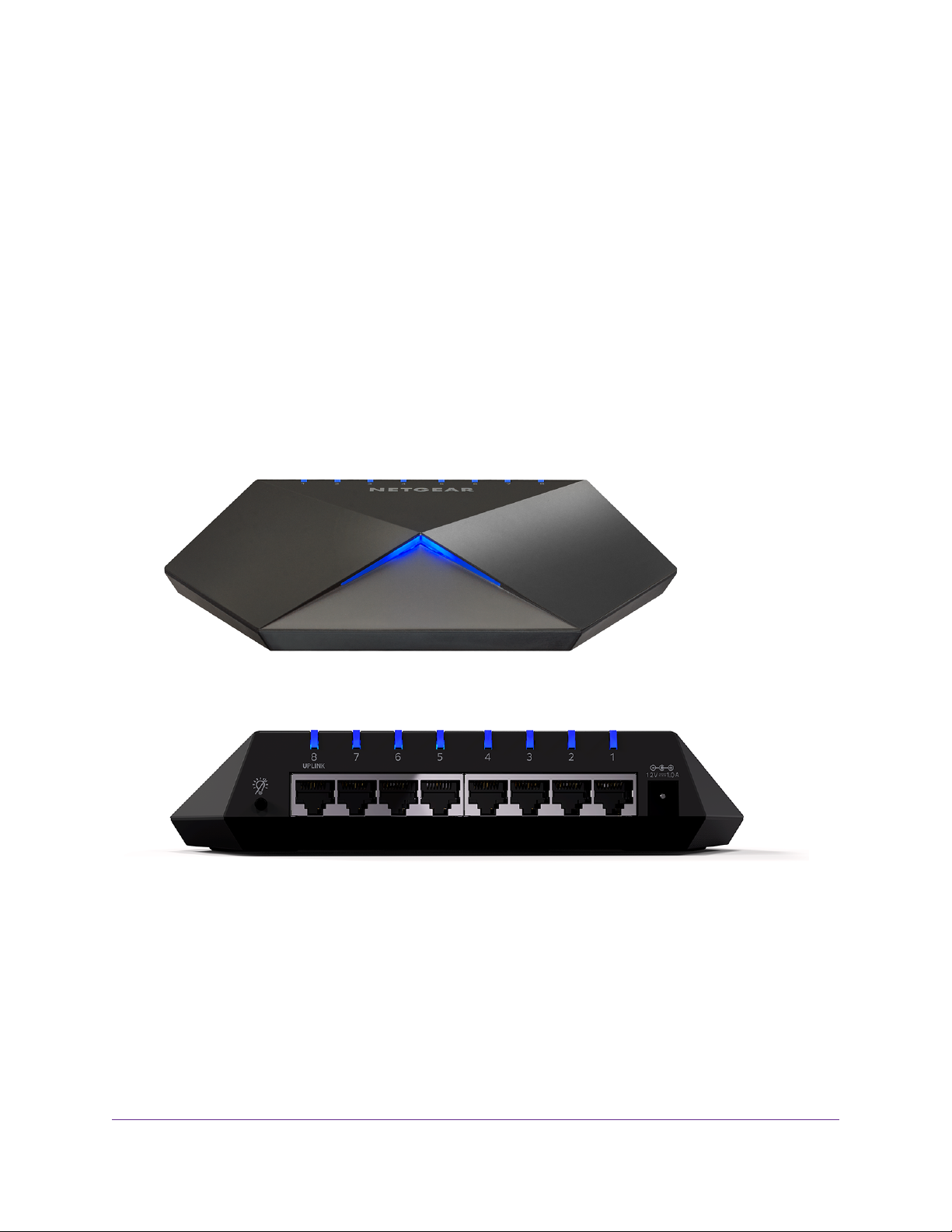
Status LEDs
Status LEDs are located on the top panel and back panel of the switch.
Figure 1. Power LED
Figure 2. Port LEDs
Hardware Overview of the Switch
6
Page 7
Nighthawk S8000 Gaming & Streaming Advanced 8-Port Gigabit Ethernet Switch (GS808E)
Table 1. LED descriptions
DescriptionLED
Power LED
Port LEDs (1 through 8)
For information about controlling the LEDs, see Control the Power LED on page 70 and Control the Port
LEDs on page 69.
Off. No po w er is supplied to the switch or the switch functions in Stealth Mode with its Power LED
disabled (see Control the Power LED on page 70).
Solid blue. Power is supplied to the switch and the switch is ready for operation.
Off. No link with a po wered-on device is detected or the active ports function in Stealth Mode with
their Port LEDs disabled (see Control the Port LEDs on page 69).
Solid blue. A link with a powered-on device is detected.
Blinking blue.Traffic is detected.
All port LEDs blinking red in a scrolling pattern. Firmware is being loaded onto the switch.
All port LEDs for ports in use blinking blue fast.The switch detected a network loop. For more
information, see Detect a Network Loop on page 79.
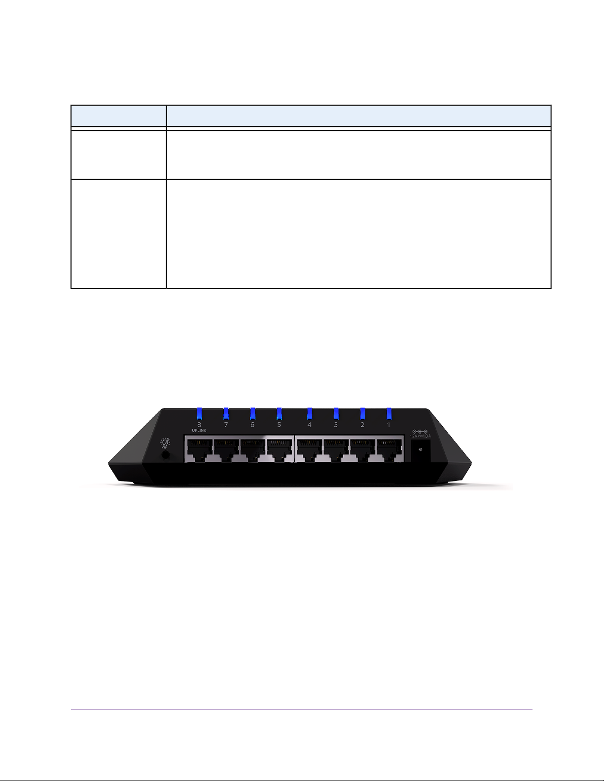
Back Panel
The back panel of the switch provides a button, eight ports, and a DC power connector.
Figure 3. Switch back panel
Viewed from left to right, the back panel contains the following components:
• LED button. One button to turn the port LEDs on and off.
• Gigabit Ethernet ports. Eight Gigabit Ethernet RJ-45 LAN ports:
- Port 8 (UPLINK). Connect this port to a LAN port on a router that is connected to the Internet.
- Ports 7 through 3. Connect these ports to your network devices, other than your main streaming
device (see Port 2) and main gaming device (see Port 1).
- Port 2. Connect this port to your main streaming device.
- Port 1. Connect this port to your main gaming device.
Hardware Overview of the Switch
7
Page 8
Nighthawk S8000 Gaming & Streaming Advanced 8-Port Gigabit Ethernet Switch (GS808E)
We recommend these port connections for the one-touch performance presets (see Apply a P erformance
Preset Mode on page 20). However, you can save custom performance presets and use different port
connections (see Manage Custom Performance Preset Modes on page 26).
• DC power connector. One 12V, 1.0 A DC connector for the power adapter.
The RESET button is located on the bottom panel of the switch. Press the RESET
Note
button for five seconds to reset the switch to factory default settings. For more
information, see Return the Switch to Its Factory Default Settings on page 66.
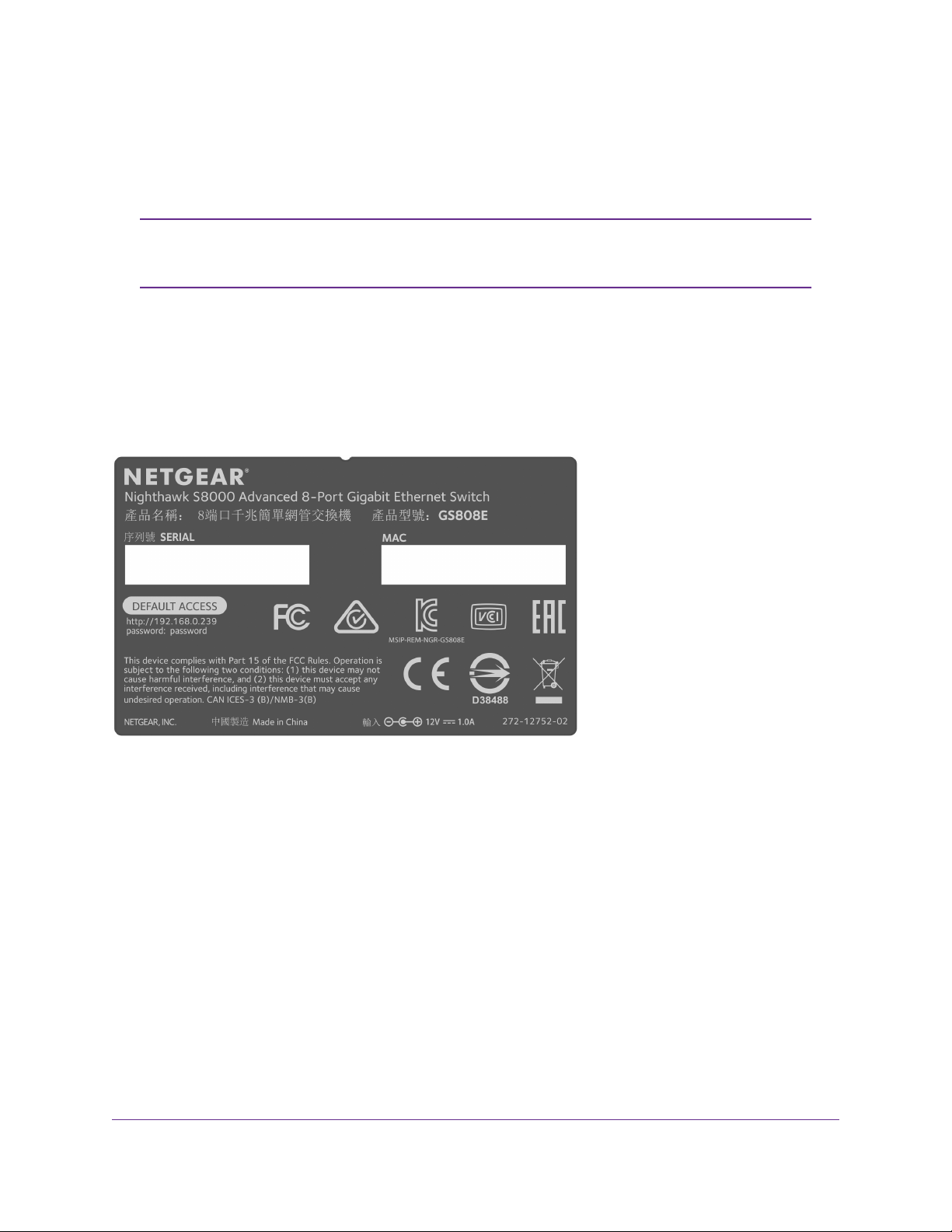
Switch Label
The switch label on the bottom panel of the switch sho ws the serial number , MA C address, and def ault login
information of the switch.
Figure 4. Switch label
Hardware Overview of the Switch
8
Page 9

Install and Access the Switch in Your Network
This chapter describes how you can install and access the switch in your network.
The chapter contains the following sections:
• Set Up the Switch in Your Network and Power On the Switch on page 10
• Access the Switch and Discover the IP Address of the Switch on page 11
• Set Up a Fixed IP Address for the Switch on page 13
• Access the Switch From a Mobile Device on page 18
2
9
Page 10
Nighthawk S8000 Gaming & Streaming Advanced 8-Port Gigabit Ethernet Switch (GS808E)
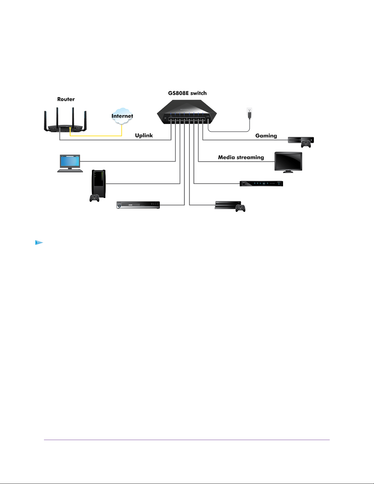
Set Up the Switch in Your Network and Power On the Switch
Figure 5. Example connections
To set up the switch in your network and power on the switch:
1. Connect LAN port 8 (UPLINK) on the switch to a LAN port on a router that is connected to the Internet.
2. On the switch, connect your devices as follows:
• Connect your gaming device to port 1.
• Connect your streaming device to port 2.
• Connect all other devices (including additional gaming and streaming devices) to remaining ports
3 through 7.
We recommend these port connections for the one-touch performance presets (see Apply a P erformance
Preset Mode on page 20). However, you can save custom performance presets and use different port
connections (see Manage Custom Performance Preset Modes on page 26).
3. Connect the power adapter to the switch and plug the power adapter into an electrical outlet.
The blue Power LED on top of the switch lights and the port LEDs for connected devices light.
Install and Access the Switch in Your Network
10
Page 11
Nighthawk S8000 Gaming & Streaming Advanced 8-Port Gigabit Ethernet Switch (GS808E)
Access the Switch and Discover the IP Address of the Switch
By default, the switch receives an IP address from a DHCP server (or a router that functions as a DHCP
server) in your network.
Access the Switch From a Windows-Based Computer
T o access the s witch fr om a Windows-based computer and discover the switch IP address:
1. Open Windows Explorer.
2. Click the Network link.
3. If prompted, enable the Network Discovery feature.
4. Under Network Infrastructure, locate the Nighthawk S8000.
5. Double-click Nighthawk S8000 (xx:xx:xx:xx:xx:xx), in which xx:xx:xx:xx:xx:xx is the MAC address of
the switch.
The login page of the management interface opens.
6. Enter the switch password.
The default password is password.The password is case-sensitive.
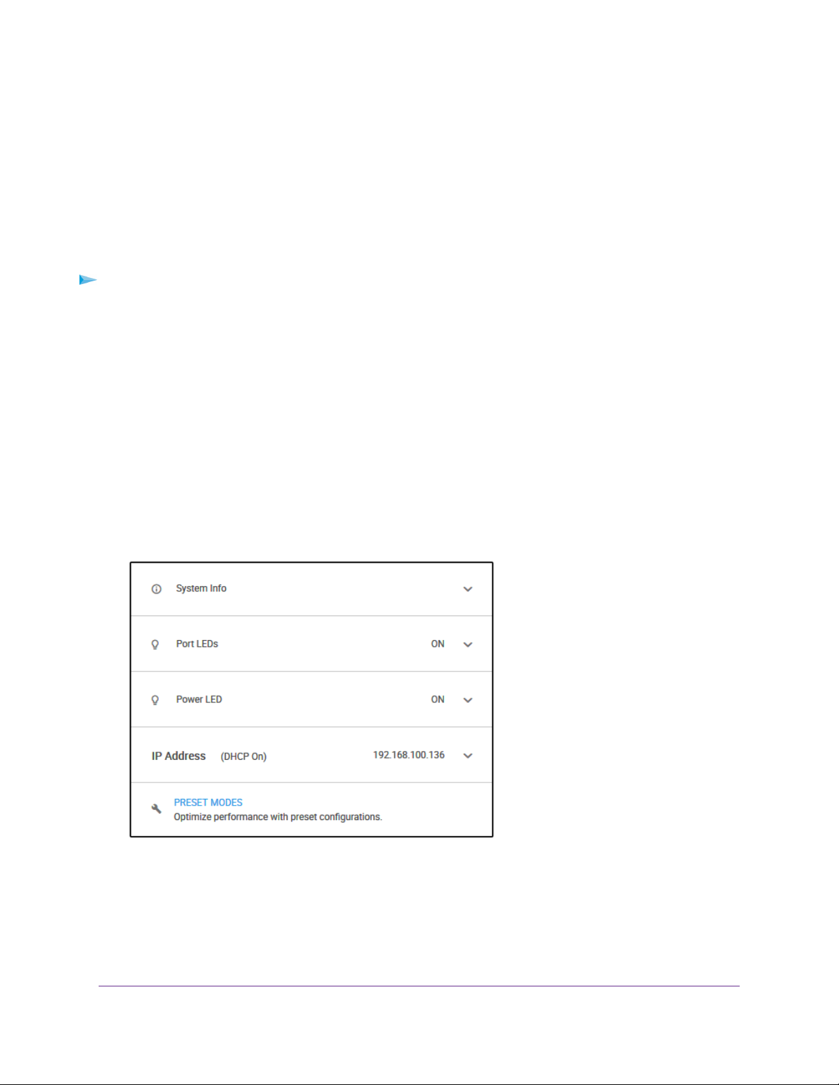
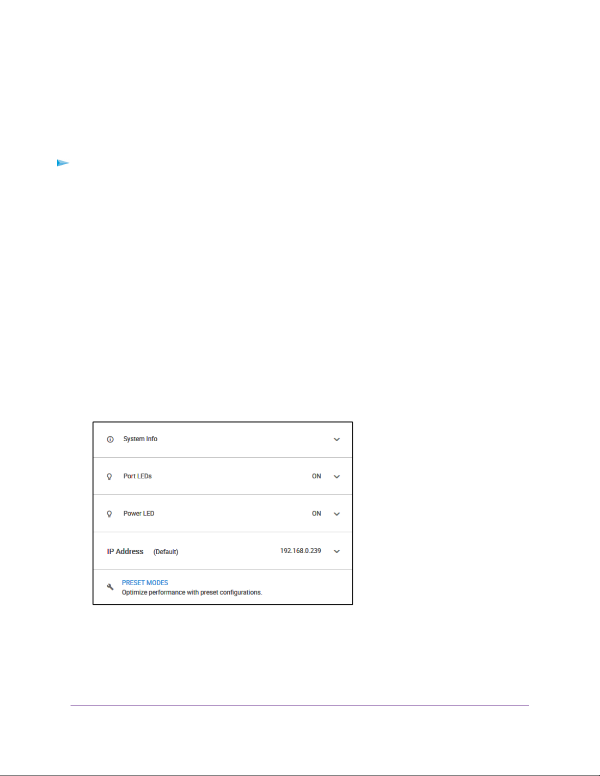
The Home page displays.
The previous figure shows the right pane (or, depending on the size of your browser page, the middle
pane) of the Home page.The pane shows the IP address that is assigned to the switch.
Install and Access the Switch in Your Network
11
Page 12

Nighthawk S8000 Gaming & Streaming Advanced 8-Port Gigabit Ethernet Switch (GS808E)
You can copy and paste the IP address into a new shortcut or bookmark it for quick access
Tip
on your computer or mobile device. However, if you reboot the switch, a dynamic IP
address (assigned by a DHCP server) might change and the bookmark might no longer
link to the login page for the switch. In this case, you must repeat Step 1 through Step 6
so that you can discover the ne w IP address of the s witch in the network and update your
bookmark accordingly.You can also set up a fixed (static) IP address for the switch (see
Set Up a Fixed IP Address for the Switch on page 13) to ensure that the new bookmark
always links to the login page for the switch, even after you reboot the switch.
Access the Switch From a Mac
To access the switch from a Mac and discover the switch IP address:
1. Open the Safari browser.
2. Select Safari > Preferences.
The General page displays.
3. Click the Advanced tab.
The Advanced page displays.
4. Select the Include Bonjour in the Bookmarks Menu check box.
5. Close the Advanced page.
6. Depending on your Mac OS version, select one of the following, in which xx:xx:xx:xx:xx:xx is the MAC
address of the switch:
• Bookmarks > Bonjour > Nighthawk S8000 (xx:xx:xx:xx:xx:xx)
• Bookmarks > Bonjour > Webpages Nighthawk S8000 (xx:xx:xx:xx:xx:xx)
The login page of the management interface opens.
7. Enter the switch password.
The default password is password.The password is case-sensitive.
Install and Access the Switch in Your Network
12
Page 13
Nighthawk S8000 Gaming & Streaming Advanced 8-Port Gigabit Ethernet Switch (GS808E)
The Home page displays.
The previous figure shows the right pane (or, depending on the size of your browser page, the middle
pane) of the Home page.The pane shows the IP address that is assigned to the switch.
You can copy and paste the IP address into a new shortcut or bookmark it for quick access
Tip
on your computer or mobile device. However, if you reboot the switch, a dynamic IP
address (assigned by a DHCP server) might change and the bookmark might no longer
link to the login page for the switch. In this case, you must repeat Step 1 through Step 7
so that you can discover the ne w IP address of the s witch in the network and update your
bookmark accordingly.You can also set up a fixed (static) IP address for the switch (see
Set Up a Fixed IP Address for the Switch on page 13) to ensure that the new bookmark
always links to the login page for the switch, even after you reboot the switch.
Set Up a Fixed IP Address for the Switch
By default, the switch receives an IP address from a DHCP server (or a router that functions as a DHCP
server) in your network. However, the DHCP server might not always issue the same IP address to the
switch. For easy access to the switch management interface, you can set up a fixed (static) IP address on
the switch.This allows you to manage the switch anytime from a mobile device because the switch IP
address remains the same.
To change the IP address of the switch, you can connect to the switch by one of the following methods:
• Through a network connection. If the switch and your computer are connected to the same network
(which is the most likely situation), you can change the IP address of the switch through a network
connection (see Set Up a Fixed IP Address for the Switch Through a Network Connection on page 14).
• Through a direct connection. If the unlikely situation that the switch is not connected to a netw ork, or
for some reason you cannot connect to the switch over a network connection, you can change the IP
address of the switch by using an Ethernet cable and making a direct connection to the s witch (see Set
Up a Fixed IP Address for the Switch By Connecting Directly to the Switch Off-Network on page 16).
Install and Access the Switch in Your Network
13
Page 14
Nighthawk S8000 Gaming & Streaming Advanced 8-Port Gigabit Ethernet Switch (GS808E)
Set Up a Fixed IP Address for the Switch Through a Network Connection
If the switch and your computer are connected to the same network (which is the most the likely situation),
you can change the IP address of the switch through a network connection.
To disable the DHCP client of the s witch and c hange the IP address of the s witc h to a fixed
IP address by using a network connection:
1. Open a web browser from a computer that is connected to the same network as the switch.
2. Enter the IP address that is assigned to the switch.
The login page opens.
3. Enter the switch password.
The default password is password.The password is case-sensitive.
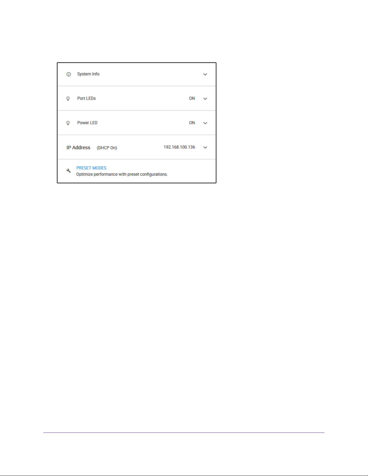
The Home page displays.
The previous figure shows the right pane (or, depending on the size of your browser page, the middle
pane) of the Home page.
Install and Access the Switch in Your Network
14
Page 15
Nighthawk S8000 Gaming & Streaming Advanced 8-Port Gigabit Ethernet Switch (GS808E)
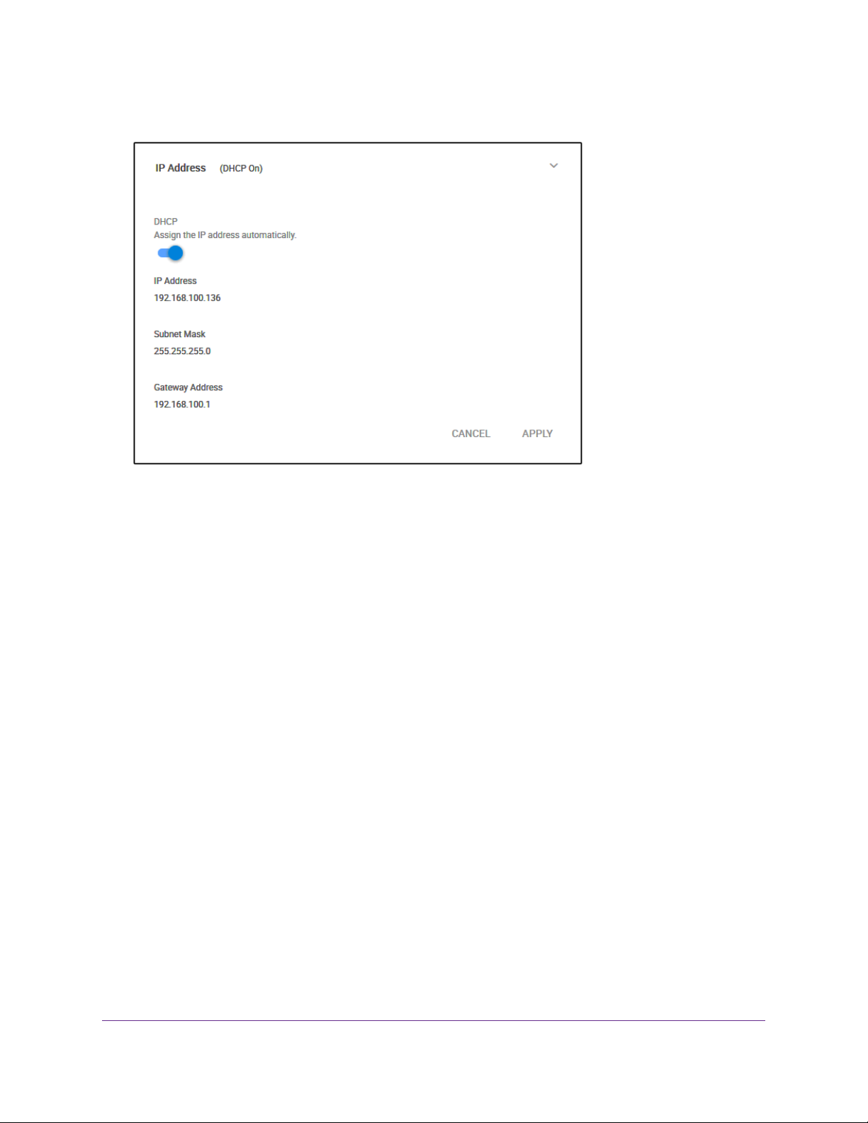
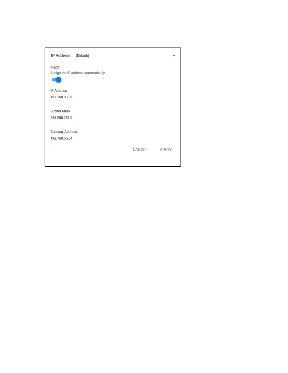
4. Select IP Address (DHCP On).
The button in the DHCP section displays blue because the DHCP client of the switch is enabled.
5. Click the button in the DHCP section.
The button displays white, indicating that the DHCP client of the switch is disabled, and the IP address
fields become editable.
6. Enter the fixed (static) IP address that you want to assign to the s witch and the associated subnet mask
and gateway IP address.
You can also either leave the address in the IP Address field as it is (with the IP address that was
issued by the DHCP server) or change the last three digits of the IP address to an unused IP address.
7. Write down the complete fixed IP address.
You can bookmark it later.
8. Click the APPLY button.
Your settings are saved.Your switch web session is disconnected when you change the IP address.
9. If the login page does not display, in the address field of your web browser, enter the new IP address
of the switch.
The login page displays.
10. For easy access to the management interface, bookmark the page on your computer.
Install and Access the Switch in Your Network
15
Page 16
Nighthawk S8000 Gaming & Streaming Advanced 8-Port Gigabit Ethernet Switch (GS808E)
Set Up a Fixed IP Address for the Switc h By Connecting Directly to the Switch Off-Network
If the unlikely situation that the switch is not connected to a network, or f or some reason you cannot connect
to the switch ov er a netw ork connection, you can change the IP address of the switch by using an Ethernet
cable and making a direct connection to the switch.
To disable the DHCP client of the s witch and c hange the IP address of the s witc h to a fixed
IP address by using a direct connection:
1. Connect an Ethernet cable from your computer to an Ethernet port on the switch.
2. Change the IP address of your computer to be in the same subnet as the default IP address of the
switch.
The default IP address of the switch is 192.168.0.239.This means that y ou must change the IP address
of the computer to be on the same subnet as the default IP address of the switch (192.168.0.x).
The method to change the IP address on your computer depends on the operating system of your
computer.
3. Open a web browser from a computer that is connected to the switch directly through an Ethernet cable.
4. Enter 192.168.0.239 as the IP address of the switch.
The login page opens.
5. Enter the switch password.
The default password is password.The password is case-sensitive.
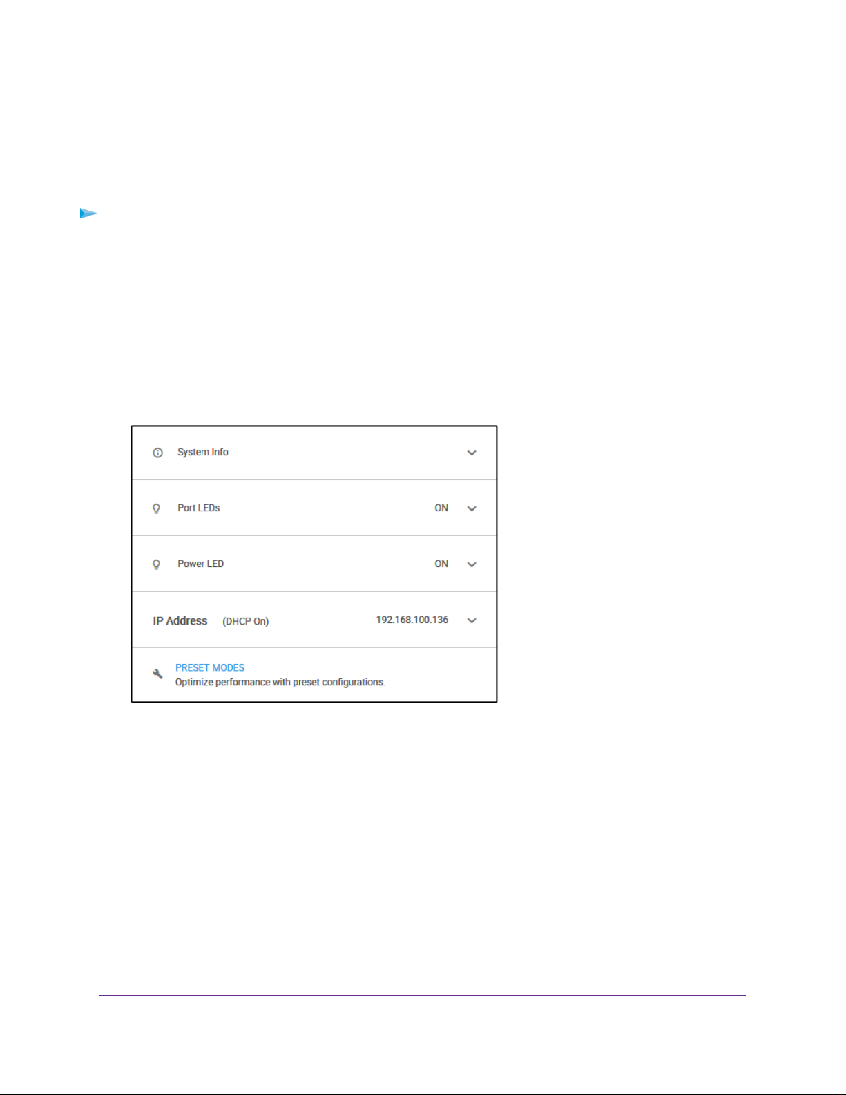
The Home page displays.
The previous figure shows the right pane (or, depending on the size of your browser page, the middle
pane) of the Home page.
Install and Access the Switch in Your Network
16
Page 17
Nighthawk S8000 Gaming & Streaming Advanced 8-Port Gigabit Ethernet Switch (GS808E)
6. Select IP Address (Default).
The button in the DHCP section displays blue because the DHCP client of the switch is enabled.
7. Click the button in the DHCP section.
The button displays white, indicating that the DHCP client of the switch is disabled, and the IP address
fields become editable.
8. Enter the fixed (static) IP address that you want to assign to the s witch and the associated subnet mask
and gateway IP address.
9. Write down the complete fixed IP address.
You can bookmark it later.
10. Click the APPLY button.
Your settings are saved.Your switch web session is disconnected when you change the IP address.
11. Disconnect the switch from your computer and install the switch in your network.
For more information, see Set Up the Switch in Your Network and Power On the Switch on page 10.
12. Restore your computer to its original IP address.
13. Verify that you can connect to the switch with its new IP address:
a. Open a web browser from a computer that is connected to the same network as the switch.
b. Enter the new IP address that you assigned to the switch.
The login page opens.
c. Enter the switch password.
The default password is password.The password is case-sensitive.
The Home page displays.
Install and Access the Switch in Your Network
17
Page 18

Nighthawk S8000 Gaming & Streaming Advanced 8-Port Gigabit Ethernet Switch (GS808E)
Access the Switch From a Mobile Device
Although you can access the switch management interface from the IP address at which you discovered
the switch in your network (see Access the Switch and Discover the IP Address of the Switch on page 11),
that IP address could change if the DHCP server issues another IP address to the switch. If you set up a
fixed IP address (see Set Up a Fixed IP Address for the Switch on page 13), you can then bookmark the
web page for that IP address to quickly access the management interface on your mobile device.
To access the switch from a mobile device:
1. Open a web browser, and in the address bar, type the IP address of the switch.
2. For easy access to the management interface, bookmark the page on your mobile device.
3. Enter the switch password.
The default password is password.The password is case-sensitive.
The Home page displays.
Install and Access the Switch in Your Network
18
Page 19

Optimize the Switch Performance
This chapter describes how you can optimize the performance of the switch.
The chapter contains the following sections:
• Apply a Performance Preset Mode on page 20
• Manage Custom Performance Preset Modes on page 26
• Manually Set the Quality of Service Mode and Port Rate Limits on page 30
• Manage Broadcast Filtering and Set Port Storm Control Rate Limits on page 35
• Manage Individual Port Settings on page 37
3
19
Page 20

Nighthawk S8000 Gaming & Streaming Advanced 8-Port Gigabit Ethernet Switch (GS808E)
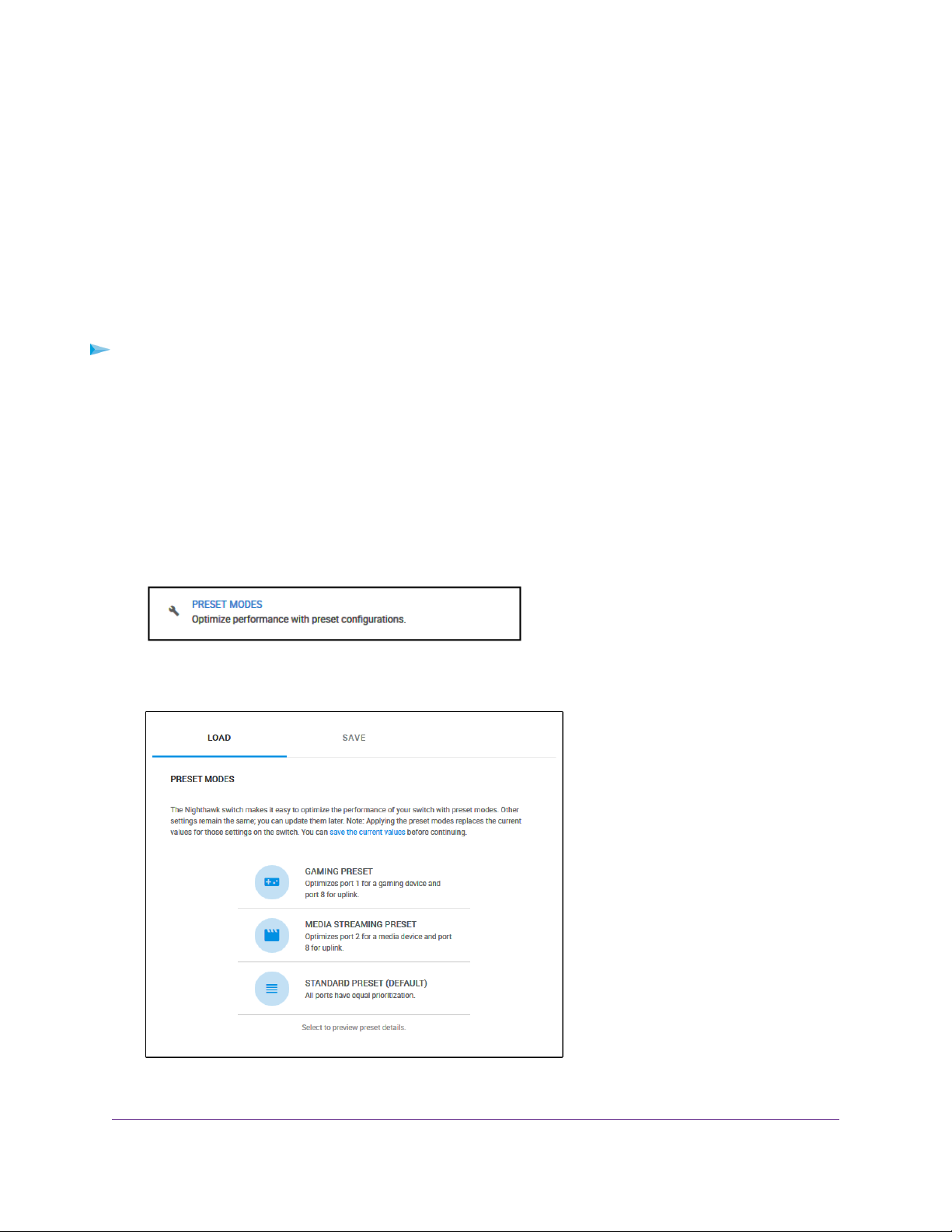
Apply a Performance Preset Mode
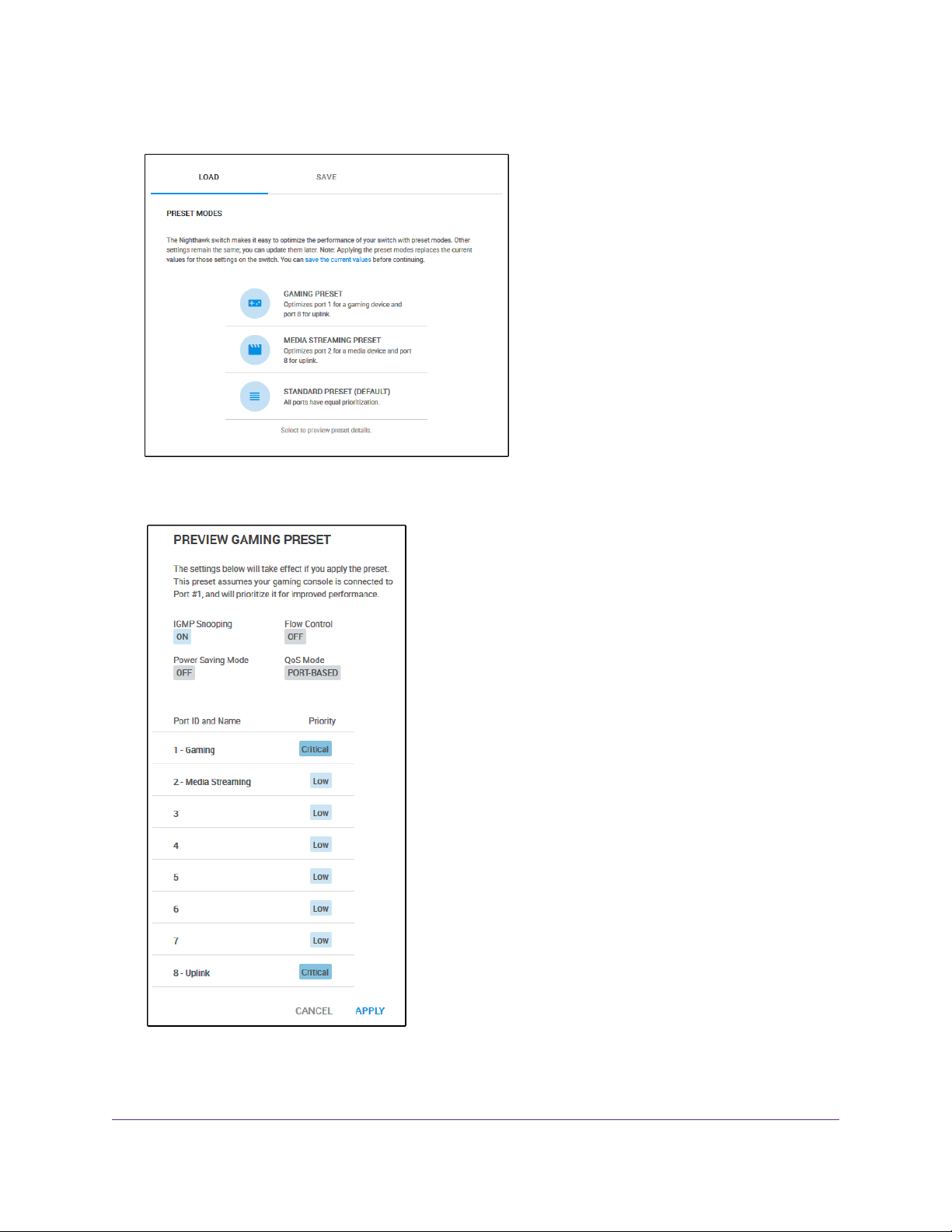
The switch comes with three predefined preset modes that let you optimize the performance of the switch
with a preset configuration.These modes include a gaming mode, a media streaming mode, and a standard
mode.The switch also provides two custom preset modes that you can define with a preset configuration
and save for easy retrieval (see Manage Custom Performance Preset Modes on page 26).
A preset mode affects the Quality of Service (QoS) and port prioritization of the switch.
Apply the Gaming Preset Mode
The Gaming Preset mode minimizes the data delay (latency) of traffic that the switch manages so that
gaming network traffic can be processed very quickly. If you use the Gaming Preset mode , be sure that y ou
connect your gaming device to port 1 and the uplink to your router to port 8.
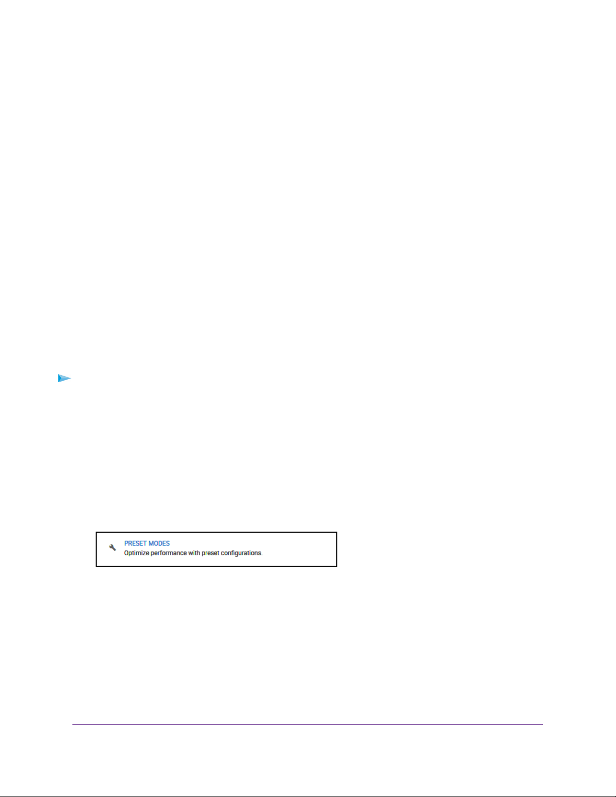
Applying the Gaming Preset mode does the following:
• Sets the QoS port priority for ports 1 and 8 to Critical.
• Sets the QoS port priority for ports 2 through 7 to Low.
• Enables IGMP snooping for the s witch (for more inf ormation, see Manage IGMP Snooping on page 53).
• Disables flow control for all ports (for more information, Manage Flow Control for a Port on page 41).
• Disables power saving for the switch (for more information, see Manage the Power Saving Mode on
page 68).
• Sets the QoS mode to port-based (for more information, see Use Port-Based Quality of Service and
Set Port Priorities on page 30).
Before you apply the Gaming Preset mode, you can save your current QoS, port prioritization, multicast,
flow control, and IGMP snooping settings and other settings as a custom preset mode (see Save Your
Quality of Service Settings as a Custom Preset Mode on page 26) so that you can easily revert to your
current QoS configuration.
To apply the Gaming Preset mode:
1. Open a web browser from a computer that is connected to the same network as the switch or to the
switch directly through an Ethernet cable.
2. Enter the IP address that is assigned to the switch.
The login page opens.
3. Enter the switch password.
The default password is password.The password is case-sensitive.
The Home page displays.
Optimize the Switch Performance
20
Page 21
Nighthawk S8000 Gaming & Streaming Advanced 8-Port Gigabit Ethernet Switch (GS808E)
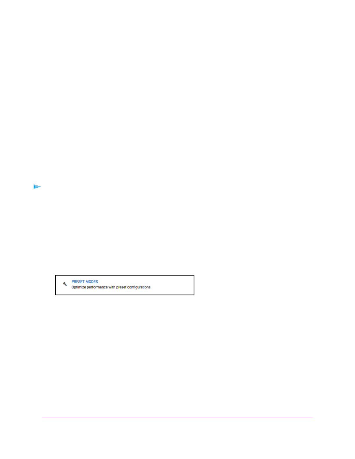
4. Select PRESET MODES.
5. Select GAMING PRESET.
6. Click the APPLY button.
Your settings are saved.
Optimize the Switch Performance
21
Page 22
Nighthawk S8000 Gaming & Streaming Advanced 8-Port Gigabit Ethernet Switch (GS808E)
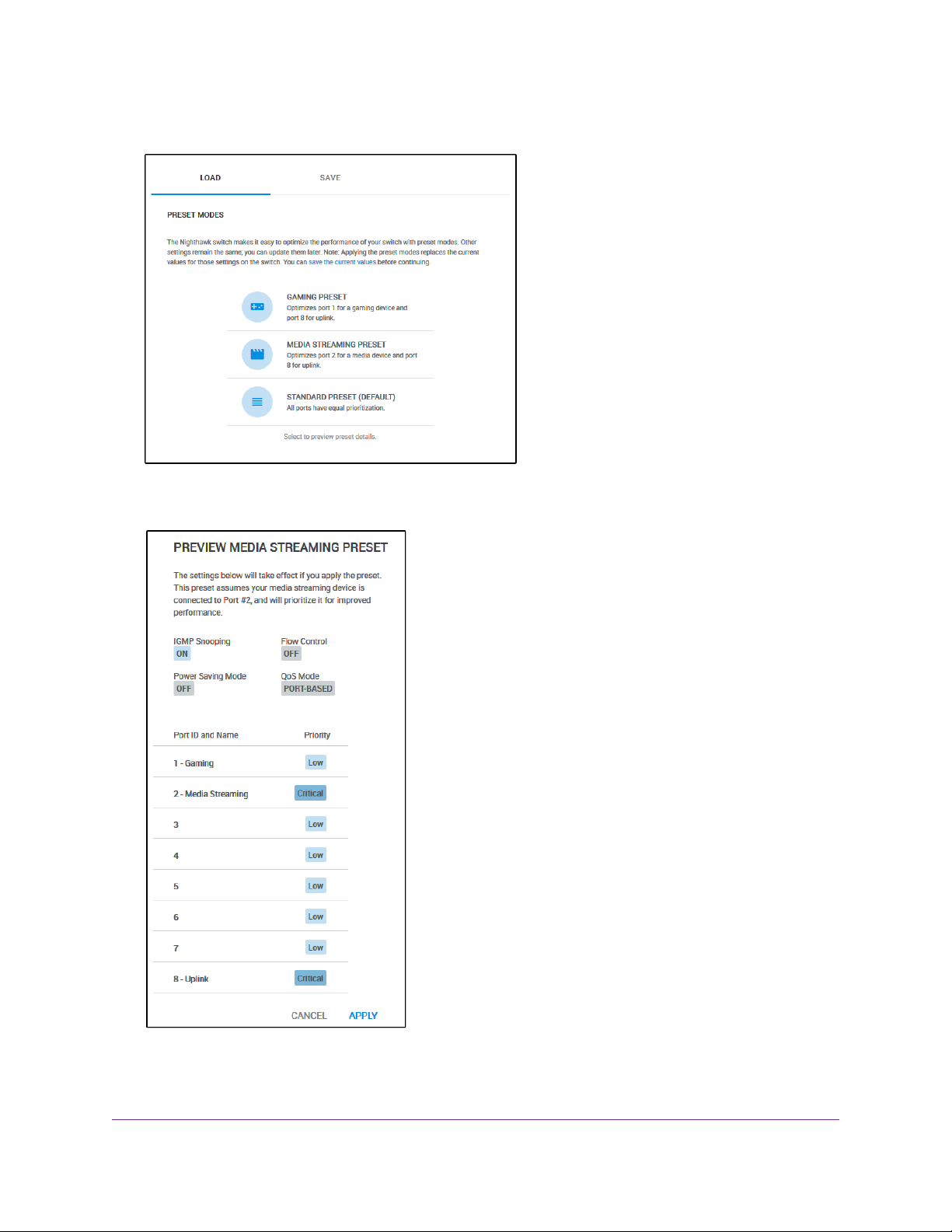
Apply the Media Streaming Preset Mode
The Media Streaming Preset mode maximizes the throughput of traffic that the switch manages so that
streaming media such as music, videos, and movies can be processed very quickly. If you use the Media
Streaming mode, be sure that you connect your media streaming device to port 2 and the uplink to your
router to port 8.
Applying the Media Streaming Preset mode does the following:
• Sets the QoS port priority for ports 2 and 8 to Critical.
• Sets the QoS port priority for ports 1 and 3 through 7 to Low.
• Enables IGMP snooping for the s witch (for more inf ormation, see Manage IGMP Snooping on page 53).
• Disables flow control for all ports (for more information, Manage Flow Control for a Port on page 41).
• Disables power saving for the switch (for more information, see Manage the Power Saving Mode on
page 68).
• Sets the QoS mode to port-based (for more information, see Use Port-Based Quality of Service and
Set Port Priorities on page 30).
Before you apply the Media Streaming Preset mode, you can save your current QoS, port prioritization,
multicast, flow control, and IGMP snooping settings and other settings as a custom preset mode (see Sav e
Your Quality of Service Settings as a Custom Preset Mode on page 26) so that y ou can easily rev ert to your
current QoS configuration.
To apply the Media Streaming Preset mode:
1. Open a web browser from a computer that is connected to the same network as the switch or to the
switch directly through an Ethernet cable.
2. Enter the IP address that is assigned to the switch.
The login page opens.
3. Enter the switch password.
The default password is password.The password is case-sensitive.
The Home page displays.
Optimize the Switch Performance
22
Page 23
Nighthawk S8000 Gaming & Streaming Advanced 8-Port Gigabit Ethernet Switch (GS808E)
4. Select PRESET MODES.
5. Select MEDIA STREAMING PRESET.
6. Click the APPLY button.
Your settings are saved.
Optimize the Switch Performance
23
Page 24
Nighthawk S8000 Gaming & Streaming Advanced 8-Port Gigabit Ethernet Switch (GS808E)
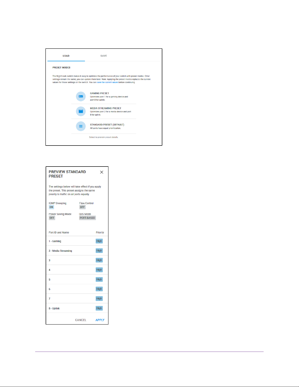
Apply the Standard Preset Mode
The Standard Preset mode, which is the default mode, gives all ports equal prioritization.
Applying the Standard Preset mode does the following:
• Sets the QoS port priority for all ports to High.
• Enables IGMP snooping for the s witch (for more inf ormation, see Manage IGMP Snooping on page 53).
• Disables flow control for all ports (for more information, Manage Flow Control for a Port on page 41).
• Disables power saving for the switch (for more information, see Manage the Power Saving Mode on
page 68).
• Sets the QoS mode to port-based (for more information, see Use Port-Based Quality of Service and
Set Port Priorities on page 30).
Before you apply the Standard Preset mode, you can save your current QoS, port prioritization, multicast,
flow control, and IGMP snooping settings and other settings as a custom preset mode (see Save Your
Quality of Service Settings as a Custom Preset Mode on page 26) so that you can easily revert to your
current QoS configuration.
To apply the Standard Preset mode:
1. Open a web browser from a computer that is connected to the same network as the switch or to the
switch directly through an Ethernet cable.
2. Enter the IP address that is assigned to the switch.
The login page opens.
3. Enter the switch password.
The default password is password.The password is case-sensitive.
The Home page displays.
Optimize the Switch Performance
24
Page 25
Nighthawk S8000 Gaming & Streaming Advanced 8-Port Gigabit Ethernet Switch (GS808E)
4. Select PRESET MODES.
5. Select STANDARD PRESET (DEFAULT).
6. Click the APPLY button.
Your settings are saved.
Optimize the Switch Performance
25
Page 26
Nighthawk S8000 Gaming & Streaming Advanced 8-Port Gigabit Ethernet Switch (GS808E)
Manage Custom Performance Preset Modes
You can save your current Quality of Service (QoS) settings as a custom preset mode, including the settings
for IGMP snooping, flow control, the pow er saving mode, the QoS mode, and the priorities of the individual
ports.You can also rename or delete these custom preset modes.
Save Your Quality of Service Settings as a Custom Preset Mode
Before you apply a performance preset mode (see Apply a Performance Preset Mode on page 20), you
can save your current Quality of Service (QoS) settings as a custom preset mode.
To save your QoS settings as a custom preset mode:
1. Open a web browser from a computer that is connected to the same network as the switch or to the
switch directly through an Ethernet cable.
2. Enter the IP address that is assigned to the switch.
The login page opens.
3. Enter the switch password.
The default password is password.The password is case-sensitive.
The Home page displays.
4. Select PRESET MODES.
Optimize the Switch Performance
26
Page 27

Nighthawk S8000 Gaming & Streaming Advanced 8-Port Gigabit Ethernet Switch (GS808E)
5. Click the SAVE tab.
6. In the Preset Mode Name field, enter a name from 1 to 16 characters for the custom preset mode.
7. Select the Slot 1 or 2 button.
You can save two custom preset modes, one in each slot.
8. Click the APPLY button.
Your settings are saved.The preset custom mode is displayed on the PRESET MODES page.
Rename a Custom Preset Mode
Ater you save a custom preset mode, you can rename the mode.
To rename a custom preset mode:
1. Open a web browser from a computer that is connected to the same network as the switch or to the
switch directly through an Ethernet cable.
2. Enter the IP address that is assigned to the switch.
The login page opens.
3. Enter the switch password.
The default password is password.The password is case-sensitive.
The Home page displays.
Optimize the Switch Performance
27
Page 28

Nighthawk S8000 Gaming & Streaming Advanced 8-Port Gigabit Ethernet Switch (GS808E)
4. Select PRESET MODES.
5. Click the SAVE tab.
6. Select the Slot 1 or 2 button.
7. In the Preset Mode Name field, enter a new name from 1 to 16 characters for the custom preset mode .
8. Click the RENAME button.
Your settings are saved.
Optimize the Switch Performance
28
Page 29

Nighthawk S8000 Gaming & Streaming Advanced 8-Port Gigabit Ethernet Switch (GS808E)
Delete a Custom Preset Mode
You can delete a custom preset mode that you no longer need.
To delete a custom preset mode:
1. Open a web browser from a computer that is connected to the same network as the switch or to the
switch directly through an Ethernet cable.
2. Enter the IP address that is assigned to the switch.
The login page opens.
3. Enter the switch password.
The default password is password.The password is case-sensitive.
The Home page displays.
4. Select PRESET MODES.
5. Select the custom preset mode.
The PREVIEW page displays.
6. Click the DELETE button.
Your settings are saved.The custom preset mode is removed from the PRESET MODES pages.
Optimize the Switch Performance
29
Page 30

Nighthawk S8000 Gaming & Streaming Advanced 8-Port Gigabit Ethernet Switch (GS808E)
Manually Set the Quality of Service Mode and Port Rate Limits
Instead of using performance preset modes, you can manually set the Quality of Service (QoS) modes to
manage traffic:
• Port-based QoS mode. Lets you set the priority (low, medium, high, or critical) for individual port
numbers and lets you set rate limits for incoming and outgoing traffic for individual ports. If broadcast
filtering is enabled, you can also set the storm control rate for incoming traffic for individual ports.
• 802.1P/DSCP QoS mode. Applies pass-through prioritization that is based on tagged pack ets and lets
you set rate limits for incoming and outgoing traffic for individual ports. If broadcast filtering is enabled,
you can also set the storm control rate for incoming traffic for individual ports.
This QoS mode applies only to devices that support 802.1P and Differentiated Services Code Point
(DSCP) tagging. For devices that do not support 802.1P and DSCP tagging, ports are not prioritized
but the configured rate limit is still applied.
You can limit the rate of incoming traffic, outgoing traffic, or both on a port to prevent the port (and the device
that is attached to it) from taking up too much bandwidth on the switch. Rate limiting, which you can set for
individual ports in either QoS mode, simply means that the switch slows down all traffic on a port so that
traffic does not exceed the limit that you set f or that port. If you set the r ate limit on a port too low , you might,
for example, see degraded video stream quality, sluggish response times during online activity, and other
problems.
Use Port-Based Quality of Service and Set Port Priorities
Port-based priority is the default QoS mode on the switch and the preset performance modes (gaming,
media streaming, and standard) are port-based.
If the QoS mode on the switch is 802.1P/DSCP, we recommend that you first save
Note
your current QoS settings as a custom preset mode before y ou change the QoS mode
to the Port-based mode. For more information, see Save Your Quality of Service
Settings as a Custom Preset Mode on page 26.
For each port, you can set the priority and the rate limits both for incoming and outgoing traffic:
• Port priority.The switch services traffic from ports with a critical priority before traffic from ports with
a high, medium, or low priority . Similarly, the switch services traffic from ports with a high priority before
traffic from ports with a medium or low priority. If severe network congestion occurs, the switch might
drop packets with a low priority.
• Port rate limits.The switch accepts traffic on a port at the rate (the speed of the data transfer) that y ou
set for incoming traffic on that port.The switch transmits traffic from a port at the rate that you set for
outgoing traffic on that port.You can select each rate limit as a predefined data transfer threshold from
512 Kbps to 512 Mbps.
If you set a port rate limit, the actual rate might fluctuate, depending on the type of
Note
traffic that the port is processing.
Optimize the Switch Performance
30
Page 31

Nighthawk S8000 Gaming & Streaming Advanced 8-Port Gigabit Ethernet Switch (GS808E)
To use the Port-based QoS mode and set the priority and rate limits for ports:
1. Open a web browser from a computer that is connected to the same network as the switch or to the
switch directly through an Ethernet cable.
2. Enter the IP address that is assigned to the switch.
The login page opens.
3. Enter the switch password.
The default password is password.The password is case-sensitive.
The Home page displays.
4. From the menu at the top of the page, select PRIORITIZATION.
The Prioritization/Quality of Service (QoS) page displays.
5. If the selection from the QoS Mode menu is 802.1P/DSCP, do the following to change the selection to
Port-based:
a. In the left pane, from the QoS Mode menu, select Port-based.
A pop-up warning window opens.
b. Click the CONTINUE button.
The pop-up window closes.
For information about broadcast filtering, see Manage Broadcast Filtering and Set
Note
Port Storm Control Rate Limits on page 35.
6. To set the port priorities, do the following:
Optimize the Switch Performance
31
Page 32

Nighthawk S8000 Gaming & Streaming Advanced 8-Port Gigabit Ethernet Switch (GS808E)
a. In the right pane, click the PRIORITY tab.
b. Click the EDIT button.
c. For each port for which you want to set the priority, select Low, Medium, High, or Critical from the
individual menu for the port.
The default selection is High.
d. Click the APPLY button.
Your settings are saved and the EDIT PRIORITY page closes.
7. To set rate limits, do the following:
Optimize the Switch Performance
32
Page 33

Nighthawk S8000 Gaming & Streaming Advanced 8-Port Gigabit Ethernet Switch (GS808E)
a. In the right pane, click the RATE LIMITS tab.
b. Click the EDIT button.
c. For each port for which you want to set rate limits , select the rate in Kbps or Mbps from the individual
In Limits and Out Limits menus for the port.
The default selection is No Limit.
d. Click the APPLY button.
Your settings are saved and the EDIT RATE LIMITS page closes.
Use 802.1P/DSCP Quality of Service
In the 802.1P/DSCP QoS mode, the switch uses the 802.1P or DSCP information in the header of an
incoming packet to prioritize the packet.With this type of QoS, you cannot control the port prioritization on
the switch because the device that sends the traffic (that is, the packets) to the switch prioritizes the traffic.
However, you can set the rate limits for individual ports on the switch.
The switch accepts traffic on a port at the rate (the speed of the data transfer) that you set for incoming
traffic on that port.The switch transmits traffic from a port at the rate that you set for outgoing traffic on that
port.You can select each rate limit as a predefined data transfer threshold from 512 Kbps to 512 Mbps.
Optimize the Switch Performance
33
Page 34

Nighthawk S8000 Gaming & Streaming Advanced 8-Port Gigabit Ethernet Switch (GS808E)
If the QoS mode on the switch is Port-based, we recommend that you first save your
Note
current QoS settings as a custom preset mode before you change the QoS mode to
the 802.1P/DSCP QoS mode. For more inf ormation, see Save Y our Quality of Service
Settings as a Custom Preset Mode on page 26.
To use 802.1P/DSCP QoS mode and set the rate limits for ports:
1. Open a web browser from a computer that is connected to the same network as the switch or to the
switch directly through an Ethernet cable.
2. Enter the IP address that is assigned to the switch.
The login page opens.
3. Enter the switch password.
The default password is password.The password is case-sensitive.
The Home page displays.
4. From the menu at the top of the page, select PRIORITIZATION.
The Prioritization/Quality of Service (QoS) page displays.
5. If the selection from the QoS Mode menu is Port-based, do the following to change the selection to
802.1P/DSCP:
a. In the left pane, from the QoS Mode menu, select 802.1P/DSCP.
A pop-up warning window opens.
b. Click the CONTINUE button.
The pop-up window closes.
For information about broadcast filtering, see Manage Broadcast Filtering and Set
Note
Port Storm Control Rate Limits on page 35.
6. To set rate limits, do the following:
Optimize the Switch Performance
34
Page 35

Nighthawk S8000 Gaming & Streaming Advanced 8-Port Gigabit Ethernet Switch (GS808E)
a. In the right pane, click the RATE LIMITS tab.
If broadcast filtering is disabled, only the RATE LIMITS tab displays.
b. Click the EDIT button.
c. For each port for which you want to set rate limits , select the rate in Kbps or Mbps from the individual
In Limits and Out Limits menus for the port.
The default selection is No Limit.
d. Click the APPLY button.
Your settings are saved and the EDIT RATE LIMITS page closes.
Manage Broadcast Filtering and Set Port Storm Control Rate Limits
A broadcast storm is a massive transmission of broadcast packets that are forwarded to every port on the
switch. If they are not blocked, broadcast storm packets can delay or halt the transmission of other data
and cause problems. However, you can block broadcast storms on the switch.
You can also set storm control rate limits for each port. Storm control measures the incoming broadcast,
multicast, and unknown unicast frame rates separately on each port, and discards the frames if the rate that
you set for the port is exceeded. By default, no storm control rate limit is set for a port.You can select each
storm control rate limit as a predefined data transfer threshold from 512 Kbps to 512 Mbps.
Optimize the Switch Performance
35
Page 36

Nighthawk S8000 Gaming & Streaming Advanced 8-Port Gigabit Ethernet Switch (GS808E)
To manage broadcast filtering and set the storm control rate limits for ports:
1. Open a web browser from a computer that is connected to the same network as the switch or to the
switch directly through an Ethernet cable.
2. Enter the IP address that is assigned to the switch.
The login page opens.
3. Enter the switch password.
The default password is password.The password is case-sensitive.
The Home page displays.
4. From the menu at the top of the page, select PRIORITIZATION.
5. In the left pane, click the button in the Broadcast Filtering section.
6. Click the APPLY button.
Broadcast filtering is enabled. In the right pane, the STORM CONTROL RATE tab displays.
7. To set storm control rate limits, do the following:
Optimize the Switch Performance
36
Page 37

Nighthawk S8000 Gaming & Streaming Advanced 8-Port Gigabit Ethernet Switch (GS808E)
a. In the right pane, click the STORM CONTROL RATE tab.
b. Click the EDIT button.
c. For each port for which you want to set storm control rate limits, select the rate in Kbps or Mbps
from the individual menu for the port.
The default selection is No Limit.
d. Click the APPLY button.
Your settings are saved and the EDIT STORM CONTROL RATE page closes.
8. Click the APPLY button.
Your settings are saved.
Manage Individual Port Settings
For each individual port, you can set rate limits for incoming and outgoing traffic, set the port speed (by
default, the speed is set automatically), enable flow control, and change the port name label.
Set Rate Limits for a Port
You can limit the rate of incoming traffic, outgoing traffic, or both on a port to prevent the port (and the device
that is attached to it) from taking up too much bandwidth on the switch. Rate limiting simply means that the
switch slows down all traffic on a port so that traffic does not exceed the limit that you set for that port. If
Optimize the Switch Performance
37
Page 38

Nighthawk S8000 Gaming & Streaming Advanced 8-Port Gigabit Ethernet Switch (GS808E)
you set the rate limit on a port too low, you might, for e xample , see deg r aded video stream quality, sluggish
response times during online activity, and other problems.
You also can set port rate limits (the same feature) as part of the Quality of Service configuration on the
switch (see Manually Set the Quality of Service Mode and Port Rate Limits on page 30).
To set rate limits for incoming and outgoing traffic on a port:
1. Open a web browser from a computer that is connected to the same network as the switch or to the
switch directly through an Ethernet cable.
2. Enter the IP address that is assigned to the switch.
The login page opens.
3. Enter the switch password.
The default password is password.The password is case-sensitive.
The Home page displays.
The PORT STATUS pane displays on the right or the bottom of the Home Page, depending on the size
of your browser page.
A port that is in use shows as UP. A port that is not in use shows as AVAILABLE.
4. Select a port.
The pane displays detailed information about the port.
Optimize the Switch Performance
38
Page 39

Nighthawk S8000 Gaming & Streaming Advanced 8-Port Gigabit Ethernet Switch (GS808E)
5. Click the EDIT button.
If the QoS mode on the switch is Port-based (the default setting), the Priority menu displays on the
page. If the QoS mode is 802.1P/DSCP, the Priority menu does not display.
6. From the In Rate Limit menu, Out Rate Limit menu, or both, select the rate in Kbps or Mbps.
The default selection is No Limit.
7. Click the APPLY button.
Your settings are saved.
Set the Priority for a Port
If the QoS mode on the switch is Port-based (the default setting), you can set the priority for a port.
The switch services traffic from ports with a critical priority before traffic from ports with a high, medium, or
low priority. Similarly, the switch services traffic from ports with a high priority before traffic from ports with
a medium or low priority. If severe network congestion occurs, the switch might drop packets with a low
priority.
You also can set the priority for a port (the same feature) as part of the Quality of Service configuration on
the switch (see Use Port-Based Quality of Service and Set Port Priorities on page 30).
Optimize the Switch Performance
39
Page 40

Nighthawk S8000 Gaming & Streaming Advanced 8-Port Gigabit Ethernet Switch (GS808E)
To set the priority for a port:
1. Open a web browser from a computer that is connected to the same network as the switch or to the
switch directly through an Ethernet cable.
2. Enter the IP address that is assigned to the switch.
The login page opens.
3. Enter the switch password.
The default password is password.The password is case-sensitive.
The Home page displays.
The PORT STATUS pane displays on the right or the bottom of the Home Page, depending on the size
of your browser page.
A port that is in use shows as UP. A port that is not in use shows as AVAILABLE.
4. Select a port.
The pane displays detailed information about the port.
Optimize the Switch Performance
40
Page 41

Nighthawk S8000 Gaming & Streaming Advanced 8-Port Gigabit Ethernet Switch (GS808E)
5. Click the EDIT button.
If the QoS mode on the switch is Port-based (the default setting), the Priority menu displays on the
page. If the QoS mode is 802.1P/DSCP, the Priority menu does not display.
6. From the Priority menu, select Low, Medium, High, or Critical.
The default selection is High.
7. Click the APPLY button.
Your settings are saved.
Manage Flow Control for a Port
IEEE 802.3x flow control works by pausing a port if the port becomes oversubscribed (that is, the port
receives more traffic than it can process) and dropping all traffic f or small bursts of time during the congestion
condition.
You can enable or disable flow control for an individual port. By default, flow control is disabled for all ports.
To manage flow control for a port:
1. Open a web browser from a computer that is connected to the same network as the switch or to the
switch directly through an Ethernet cable.
2. Enter the IP address that is assigned to the switch.
The login page opens.
Optimize the Switch Performance
41
Page 42

Nighthawk S8000 Gaming & Streaming Advanced 8-Port Gigabit Ethernet Switch (GS808E)
3. Enter the switch password.
The default password is password.The password is case-sensitive.
The Home page displays.
The PORT STATUS pane displays on the right or the bottom of the Home Page, depending on the size
of your browser page.
A port that is in use shows as UP. A port that is not in use shows as AVAILABLE.
4. Select a port.
The pane displays detailed information about the port.
Optimize the Switch Performance
42
Page 43

Nighthawk S8000 Gaming & Streaming Advanced 8-Port Gigabit Ethernet Switch (GS808E)
5. Click the EDIT button.
If the QoS mode on the switch is Port-based (the default setting), the Priority menu displays on the
page. If the QoS mode is 802.1P/DSCP, the Priority menu does not display.
6. In the Flow Control section, enable or disable flow control by clicking the button.
When flow control is enabled, the button displa ys blue.When flow control is disabled, the button displays
white
7. Click the APPLY button.
Your settings are saved.
Change the Speed for a Port
By default, the port speed on all ports is set automatically (that is, the setting is Auto) after the switch
determines the speed using autonegotiation with the linked device.We recommend that you lea ve the Auto
setting for the ports. However, you can select a specific port speed setting for each port or disable a port
by shutting it down manually.
To change the speed for a port or disable a port:
1. Open a web browser from a computer that is connected to the same network as the switch or to the
switch directly through an Ethernet cable.
2. Enter the IP address that is assigned to the switch.
Optimize the Switch Performance
43
Page 44

Nighthawk S8000 Gaming & Streaming Advanced 8-Port Gigabit Ethernet Switch (GS808E)
The login page opens.
3. Enter the switch password.
The default password is password.The password is case-sensitive.
The Home page displays.
The PORT STATUS pane displays on the right or the bottom of the Home Page, depending on the size
of your browser page.
A port that is in use shows as UP. A port that is not in use shows as AVAILABLE.
4. Select a port.
The pane displays detailed information about the port.
Optimize the Switch Performance
44
Page 45

Nighthawk S8000 Gaming & Streaming Advanced 8-Port Gigabit Ethernet Switch (GS808E)
5. Click the EDIT button.
If the QoS mode on the switch is Port-based (the default setting), the Priority menu displays on the
page. If the QoS mode is 802.1P/DSCP, the Priority menu does not display.
6. Select one of the following options from the Speed menu:
• Auto.The port speed is set automatically after the switch determines the speed using autonegotiation
with the linked device.This is the default setting.
• Disable.The port is shut down.
• 10M half.The port is forced to function at 10 Mbps with half-duplex.
• 10M full.The port is forced to function at 10 Mbps with full-duplex.
• 100M half.The port is forced to function at 100 Mbps with half-duplex.
• 100M full.The port is forced to function at 100 Mbps with full-duplex.
You cannot select Gigabit Ethernet as the port speed. However, if the setting from
Note
the Speed menu is Auto, the s witch can use autonegotiation to automatically set the
port speed to Gigabit Ethernet if the linked device supports that speed.
7. Click the APPLY button.
Your settings are saved.
Optimize the Switch Performance
45
Page 46

Nighthawk S8000 Gaming & Streaming Advanced 8-Port Gigabit Ethernet Switch (GS808E)
Change the Name Label for a Port
By default, only ports 1, 2, and 8 contain a port name label:
• Port 1. Gaming
• Port 2. Media Streaming
• Port 8. Uplink
Y ou can change these name labels . Other ports do not contain name labels, but you can add them. Changing
or adding a name label does not change the nature of a port, that is, it is just a label.
To change or add a name label for a port:
1. Open a web browser from a computer that is connected to the same network as the switch or to the
switch directly through an Ethernet cable.
2. Enter the IP address that is assigned to the switch.
The login page opens.
3. Enter the switch password.
The default password is password.The password is case-sensitive.
The Home page displays.
The PORT STATUS pane displays on the right or the bottom of the Home Page, depending on the size
of your browser page.
A port that is in use shows as UP. A port that is not in use shows as AVAILABLE.
4. Select a port.
The pane displays detailed information about the port.
Optimize the Switch Performance
46
Page 47

Nighthawk S8000 Gaming & Streaming Advanced 8-Port Gigabit Ethernet Switch (GS808E)
5. Click the EDIT button.
If the QoS mode on the switch is Port-based (the default setting), the Priority menu displays on the
page. If the QoS mode is 802.1P/DSCP, the Priority menu does not display.
6. In the Port Name field, type a new name label for the port.
The name label can be from 1 to 16 characters.
7. Click the APPLY button.
Your settings are saved.
Optimize the Switch Performance
47
Page 48

Manage the Switch in Your Network
This chapter describes how you can manage the switch in your network.
The chapter contains the following sections:
• Manage Switch Discovery Protocols on page 49
• Set Up Static Link Aggregation on page 51
• Manage Multicast on page 53
• Change the IP Address of the Switch on page 57
• Reenable the DHCP Client of the Switch on page 58
4
48
Page 49

Nighthawk S8000 Gaming & Streaming Advanced 8-Port Gigabit Ethernet Switch (GS808E)
Manage Switch Discovery Protocols
The switch supports Universal Plug-N-Play (UPnP), Bonjour, and NETGEAR Switch Discovery Protocol
(NSDP), any of which allows the switch to be discovered in a network.You need to know the switch IP
address to access the management interface.
As a security measure, you can disable one or more discovery protocols. However, we recommend that
you leave at least one discovery protocol enabled to allow the switch to be discovered if its IP address
changes.
Manage Universal Plug-N-Play
Universal Plug-N-Play (UPnP) allows the switch to be discovered on Window-based devices so that you
can find the IP address of the switch on your network and log in to the management interf ace of the switch.
UPnP is enabled by default. For security reasons, you can disable UPnP.
To manage UPnP:
1. Open a web browser from a computer that is connected to the same network as the switch or to the
switch directly through an Ethernet cable.
2. Enter the IP address that is assigned to the switch.
The login page opens.
3. Enter the switch password.
The default password is password.The password is case-sensitive.
The Home page displays.
4. From the menu at the top of the page, select ADVANCED SETTINGS.
The PRESET MODES page displays.
5. Select Switch Discovery.
The Switch Discovery page displays.
6. Enable or disable UPnP by clicking the button in the UPnP section.
When UPnP is enabled, the button displays blue.When UPnP is disabled, the button displays white.
7. Click the APPLY button.
Your settings are saved.
Manage the Switch in Your Network
49
Page 50

Nighthawk S8000 Gaming & Streaming Advanced 8-Port Gigabit Ethernet Switch (GS808E)
Manage Bonjour
Bonjour allows the switch to be discovered on Mac OS devices so that you can find the IP address of the
switch on your network and log in to the management interf ace of the switch. Bonjour is enab led b y default.
For security reasons, you can disable Bonjour.
To manage Bonjour:
1. Open a web browser from a computer that is connected to the same network as the switch or to the
switch directly through an Ethernet cable.
2. Enter the IP address that is assigned to the switch.
The login page opens.
3. Enter the switch password.
The default password is password.The password is case-sensitive.
The Home page displays.
4. From the menu at the top of the page, select ADVANCED SETTINGS.
The PRESET MODES page displays.
5. Select Switch Discovery.
The Switch Discovery page displays.
6. Enable or disable Bonjour by clicking the button in the Bonjour section.
When Bonjour is enabled, the button displa ys blue.When Bonjour is disab led, the button displa ys white.
7. Click the APPLY button.
Your settings are saved.
Manage NETGEAR Switch Discovery Protocol
NETGEAR Switch Discovery Protocol (NSDP) allows the switch to be discovered on NETGEAR devices
and applications so that you can find the IP address of the switch on your network and log in to the
management interface of the switch. NSDP is enabled by default. For security reasons, you can disable
NSDP.
To manage NSDP:
1. Open a web browser from a computer that is connected to the same network as the switch or to the
switch directly through an Ethernet cable.
2. Enter the IP address that is assigned to the switch.
The login page opens.
3. Enter the switch password.
The default password is password.The password is case-sensitive.
The Home page displays.
4. From the menu at the top of the page, select ADVANCED SETTINGS.
The PRESET MODES page displays.
Manage the Switch in Your Network
50
Page 51

Nighthawk S8000 Gaming & Streaming Advanced 8-Port Gigabit Ethernet Switch (GS808E)
5. Select Switch Discovery.
The Switch Discovery page displays.
6. Enable or disable NSDP by clicking the button in the NSDP section.
When NSDP is enabled, the button displays blue.When NSDP is disabled, the button displays white.
7. Click the APPLY button.
Your settings are saved.
Set Up Static Link Aggregation
Static link aggregation on the switch allows y ou to combine m ultiple Ethernet ports into a single logical link.
Your network devices treat the aggregation as if it were a single link. Depending on ho w link aggregation is
set up in your network, the link supports either increased bandwidth (a larger pipe) or fault tolerance (if one
port fails another, one takes over).
The switch supports two static LAGs with up to four ports each.That means that one static LAG can support
a link of up to 4 Gbps.
The switch does not support Link Aggregation Control Protocol (LACP).Note
You set up static link aggregation on the switch through link aggregation groups (LAG)s in the following
order:
1. Set up the LAG on the switch (see Set Up Link Aggregation Groups on page 52).
2. Connect the ports that you intend to make members of a LAG on the switch to the ports that are members
of a LAG on another device in your network (see Make a Link Aggregation Connection on page 51).
Make a Link Aggregation Connection
Before you make a physical link aggregation connection to another network device (usually a router or
another switch) that also supports link aggregation, you must first set up a link aggregation group (LA G) on
the switch (see Set Up Link Aggregation Groups on page 52). If you do not, the LAG cannot take effect.
Whether a LAG on the switch functions to support increased bandwidth or fault tolerance depends on the
LAG configuration on the other network device.
All ports that participate in a LAG (that is, the ports on both devices) must use the same speed, full duplex
mode, and flow control setting. For information about changing these settings on the switch, see Manage
Individual Port Settings on page 37.
To make link aggregation connections between the switch and other network devices:
1. Using Ethernet cables, connect each port that you intend to made a member of LAG 1 on the switch to
each port that is member of the same LAG on another network device.
LAG 1 can include ports 1 through 4.The port numbers on the other network device do not matter as
long as the ports on the other network device are members of the same LAG and the LAG consists of
the same total number of ports.
2. Using Ethernet cables, connect each port that you intend to made a member of LAG 2 on the switch to
each port that is member of the same LAG on another network device.
Manage the Switch in Your Network
51
Page 52

Nighthawk S8000 Gaming & Streaming Advanced 8-Port Gigabit Ethernet Switch (GS808E)
LAG 2 can include ports 5 through 8.The port numbers on the other network device do not matter as
long as the ports on the other network device are members of the same LAG and the LAG consists of
the same total number of ports.
Set Up Link Aggregation Groups
You set up static link aggregation on the switch by adding up to four ports to a link aggregation group (LAG)
and by enabling the LAG. However, for a LAG to take effect, you first must make sure that all ports that
participate in a LAG (that is, the ports on both devices) must use the same speed, duplex mode, and flow
control setting (see Manage Individual Port Settings on page 37 for inf ormation about changing these settings
on the switch) and you must set up a physical link aggregation connection (see Make a Link Aggregation
Connection on page 51).
To set up link aggregation groups on the switch:
1. Open a web browser from a computer that is connected to the same network as the switch or to the
switch directly through an Ethernet cable.
2. Enter the IP address that is assigned to the switch.
The login page opens.
3. Enter the switch password.
The default password is password.The password is case-sensitive.
The Home page displays.
4. From the menu at the top of the page, select ADVANCED SETTINGS.
The PRESET MODES page displays.
5. Select Link Aggregation.
Manage the Switch in Your Network
52
Page 53

Nighthawk S8000 Gaming & Streaming Advanced 8-Port Gigabit Ethernet Switch (GS808E)
6. To add ports to LAG 1, click two, three, or all port numbers from 1 to 4.
A selected port displays blue.
LAG 1 must consist of at least two ports but can consist of all ports in the range from 1 through 4.
7. To add ports to LAG 2, click two, three, or all port numbers from 5 to 8.
A selected port displays blue.
LAG 2 must consist of at least two ports but can consist of all ports in the range from 5 through 8.
8. Click the APPLY button.
Your settings are saved.
Manage Multicast
Multicast IP traffic is traffic that is destined to a host group. Host g roups are identified by Class D IP addresses,
which range from 224.0.0.0 to 239.255.255.255. Internet Group Management Protocol (IGMP) snooping
allows the switch to forward multicast traffic intelligently. Based on the IGMP query and report messages,
the switch forwards traffic only to the ports that request the multicast traffic rather than to all ports, which
could affect network performance.
IGMP snooping helps to optimize multicast performance and is especially useful for bandwidth-intensiv e IP
multicast applications such as online media streaming applications.
Manage IGMP Snooping
Internet Group Management Protocol (IGMP) snooping is enabled by default. Under some circumstances
you might want to temporarily disable IGMP snooping.
To manage IGMP snooping:
1. Open a web browser from a computer that is connected to the same network as the switch or to the
switch directly through an Ethernet cable.
2. Enter the IP address that is assigned to the switch.
The login page opens.
3. Enter the switch password.
The default password is password.The password is case-sensitive.
The Home page displays.
4. From the menu at the top of the page, select ADVANCED SETTINGS.
The PRESET MODES page displays.
Manage the Switch in Your Network
53
Page 54

Nighthawk S8000 Gaming & Streaming Advanced 8-Port Gigabit Ethernet Switch (GS808E)
5. Select Multicast.
6. Enable or disable IGMP snooping by clicking the button in the IGMP Snooping section.
When IGMP snooping is enabled, the button displa ys blue.When IGMP snooping is disab led, the button
displays white.
7. Click the APPLY button.
Your settings are saved.
Manage Blocking of Unknown Multicast Addresses
As a way to limit unnecessary multicast traffic, you can block multicast traffic from unknown multicast
addresses. If you do this, the switch forwards multicast traffic only to ports in the multicast group that the
switch learned through IGMP snooping. By default, multicast traffic from unknown addresses is allowed.
To manage blocking of unknown multicast addresses:
1. Open a web browser from a computer that is connected to the same network as the switch or to the
switch directly through an Ethernet cable.
2. Enter the IP address that is assigned to the switch.
The login page opens.
3. Enter the switch password.
The default password is password.The password is case-sensitive.
The Home page displays.
4. From the menu at the top of the page, select ADVANCED SETTINGS.
The PRESET MODES page displays.
Manage the Switch in Your Network
54
Page 55

Nighthawk S8000 Gaming & Streaming Advanced 8-Port Gigabit Ethernet Switch (GS808E)
5. Select Multicast.
6. Enable or disable the blocking of unknown multicast traffic by clicking the button in the Block Unknown
Multicast Address section.
When the blocking of unknown multicast traffic is enabled, the button displays blue.When the blocking
of unknown multicast traffic is disabled, the button displays white.
7. Click the APPLY button.
Your settings are saved.
Manage IGMPv3 IP Header Validation
You can enable IGMPv3 IP header validation so that the switch inspects whether IGMPv3 packets conform
to the IGMPv3 standard. By def ault, IGMPv3 IP header validation is disab led. If IGMPv3 IP header validation
is enabled, IGMPv3 messages must include a TTL of 1 and a ToS byte of 0xC0 (Internetwork Control). In
addition, the router alert IP option (9404) must be set.
If IGMPv3 IP header validation is enabled, s witch does not drop IGMPv1 and IGMPv2
Note
traffic but processes this traffic normally.
To manage IGMPv3 IP header validation:
1. Open a web browser from a computer that is connected to the same network as the switch or to the
switch directly through an Ethernet cable.
2. Enter the IP address that is assigned to the switch.
The login page opens.
3. Enter the switch password.
Manage the Switch in Your Network
55
Page 56

Nighthawk S8000 Gaming & Streaming Advanced 8-Port Gigabit Ethernet Switch (GS808E)
The default password is password.The password is case-sensitive.
The Home page displays.
4. From the menu at the top of the page, select ADVANCED SETTINGS.
The PRESET MODES page displays.
5. Select Multicast.
6. Enable or disable IGMPv3 IP header validation b y clic king the b utton in the Validate IGMPv3 IP Header
section.
When IGMPv3 IP header validation is enabled, the button displays blue.When IGMPv3 IP header
validation is disabled, the button displays white.
7. Click the APPLY button.
Your settings are saved.
Set Up a Static Router Port for IGMP Snooping
If your network does not include a device that sends IGMP queries, the switch cannot discover the router
port dynamically. (The router port is a port on a device in the network that performs IGMP snooping in the
network.) In this situation, select one port on the switch as the dedicated static router port for IGMP snooping,
allowing all IGMP Join and Leave messages in the network to be forwarded to this port.
To set up a static router port for IGMP snooping:
1. Open a web browser from a computer that is connected to the same network as the switch or to the
switch directly through an Ethernet cable.
2. Enter the IP address that is assigned to the switch.
The login page opens.
Manage the Switch in Your Network
56
Page 57

Nighthawk S8000 Gaming & Streaming Advanced 8-Port Gigabit Ethernet Switch (GS808E)
3. Enter the switch password.
The default password is password.The password is case-sensitive.
The Home page displays.
4. From the menu at the top of the page, select ADVANCED SETTINGS.
The PRESET MODES page displays.
5. Select Multicast.
6. From the menu in the IGMP Snooping Static Router Port section, select a specific port as the router
port or select Any to let IGMP Join and Leave messages be sent to every port on the switch.
Typically, the uplink port (that is, the port that is connected to your router or to the device that provides
your Internet connection) serves as the router port.
7. Click the APPLY button.
Your settings are saved.
Change the IP Address of the Switch
By default, the switch receives an IP address from a DHCP server (or a router that functions as a DHCP
server) in your network.
To disable the DHCP client of the s witch and c hange the IP address of the s witc h to a fixed
IP address:
1. Open a web browser from a computer that is connected to the same network as the switch or to the
switch directly through an Ethernet cable.
2. Enter the IP address that is assigned to the switch.
Manage the Switch in Your Network
57
Page 58

Nighthawk S8000 Gaming & Streaming Advanced 8-Port Gigabit Ethernet Switch (GS808E)
The login page opens.
3. Enter the switch password.
The default password is password.The password is case-sensitive.
The Home page displays.
4. Select IP Address.
The button in the DHCP section displays blue because the DHCP client of the switch is enabled.
5. Click the button in the DHCP section.
The button displays white, indicating that the DHCP client of the switch is disabled, and the IP address
fields become editable.
6. Enter the fixed (static) IP address that you want to assign to the s witch and the associated subnet mask
and gateway IP address.
7. Click the APPLY button.
A pop-up window displays a message.
8. Click the X in the pop-up window.
Your settings are saved.Your switch web session might be disconnected when you change the IP
address.
Reenable the DHCP Client of the Switch
If you disabled the DHCP client of the s witch and changed the IP address of the switch to a fixed (static) IP
address, you can reverse the situation.You can also press the RESET button for five seconds (not longer)
to reenable DHCP (see Use the RESET Button to Renew the DHCP IP Address or Reenable DHCP on
page 68).
Manage the Switch in Your Network
58
Page 59

Nighthawk S8000 Gaming & Streaming Advanced 8-Port Gigabit Ethernet Switch (GS808E)
To reenable the DHCP client on the switch:
1. Open a web browser from a computer that is connected to the same network as the switch or to the
switch directly through an Ethernet cable.
2. Enter the IP address that is assigned to the switch.
The login page opens.
3. Enter the switch password.
The default password is password.The password is case-sensitive.
The Home page displays.
4. Select IP Address.
The button in the DHCP section displays white because the DHCP client of the switch is disabled.
5. Click the button in the DHCP section.
The button displays blue, indicating that the DHCP server of the switch is enabled.
6. Click the APPLY button.
Manage the Switch in Your Network
59
Page 60

Nighthawk S8000 Gaming & Streaming Advanced 8-Port Gigabit Ethernet Switch (GS808E)
A pop-up window displays a message.
7. Click the X in the pop-up window.
Your settings are saved.The switch receives an IP address from a DHCP server (or a router that
functions as a DHCP server) in your network.Your switch web session might be disconnected when
you enable the DHCP client of the switch.
Manage the Switch in Your Network
60
Page 61

Maintain and Monitor the Switch
This chapter describes how you can maintain and monitor the switch.
The chapter contains the following sections:
• Change the Switch Password on page 62
• Check for New Switch Firmware and Upgrade the Switch on page 62
• Manage the Configuration File on page 64
• Return the Switch to Its Factory Default Settings on page 66
• Use the RESET Button to Renew the DHCP IP Address or Reenable DHCP on page 68
• Manage the Power Saving Mode on page 68
• Control the Port LEDs on page 69
• Control the Power LED on page 70
• Change the Switch Device Name on page 71
• Register the Switch on page 72
5
• View System Information on page 72
• View Switch Connections on page 73
• View the Status of a Port on page 74
61
Page 62

Nighthawk S8000 Gaming & Streaming Advanced 8-Port Gigabit Ethernet Switch (GS808E)
Change the Switch Password
The default passw ord to access the management interface of the switch is password.We recommend that
you change this password to a more secure password.The ideal password contains no dictionary words
from any language and contains uppercase and lowercase letters, numbers, and symbols. It can be up to
20 characters.
To change the switch password:
1. Open a web browser from a computer that is connected to the same network as the switch or to the
switch directly through an Ethernet cable.
2. Enter the IP address that is assigned to the switch.
The login page opens.
3. Enter the switch password.
The default password is password.The password is case-sensitive.
The Home page displays.
4. From the menu at the top of the page, select ADVANCED SETTINGS.
The PRESET MODES page displays.
5. Select Change Password.
The CHANGE PASSWORD page displays.
6. In the Old Password field, type the current password for the switch.
7. Type the new password in the New Password field and in the Retype New Password field.
8. Click the APPLY button.
Your settings are saved. Keep the new pass word in a secure location so that y ou can access the s witch
in the future.
Check for New Switch Firmware and Upgrade the Switch
You can check for the latest firmware version through the management interface of the switch, download
the firmware, and upload the firmware to the switch. If firmware release notes are availab le with new firmware,
read the release notes to find out if you must reconfigure the switch after upgrading.
To check for new switch firmware and upgrade the switch:
1. Open a web browser from a computer that is connected to the same network as the switch or to the
switch directly through an Ethernet cable.
2. Enter the IP address that is assigned to the switch.
The login page opens.
3. Enter the switch password.
The default password is password.The password is case-sensitive.
The Home page displays.
Maintain and Monitor the Switch
62
Page 63

Nighthawk S8000 Gaming & Streaming Advanced 8-Port Gigabit Ethernet Switch (GS808E)
4. From the menu at the top of the page, select ADVANCED SETTINGS.
The PRESET MODES page displays.
5. Select Firmware.
The page displays the current firmware of the switch.
6. To check if new firmware is available, click the link in the FIRMWARE section.
A NETGEAR web page opens.
7. If new firmware is available, download the firmware file to your computer.
If the file does not end in .bin, you might need to unzip the file. For example, if the file ends in .rar,
you must unzip the file.
8. In the FIRMWARE UPDATE section, click the blue file icon, navigate to the firmware file that you just
downloaded, and select the file.
An example of a firmware file name is S8000_V1.0.0.1.bin.
9. Click the UPLOAD button.
A pop-up window displays a warning and the firmware upgrade process starts.
WARNING:
Do not interrupt the network connection or power to the switch during the
firmware upgrade process. Do not disconnect any Ethernet cables or power
off the switch until the firmware upgrade process and switch reboot are
complete.
Your switch web session is disconnected and you must log back in to the management interface.
Maintain and Monitor the Switch
63
Page 64

Nighthawk S8000 Gaming & Streaming Advanced 8-Port Gigabit Ethernet Switch (GS808E)
Manage the Configuration File
The configuration settings of the switch are stored within the switch in a configuration file.You can back up
(save) this file to your computer or restore it from your computer to the switch.
Back Up the Switch Configuration
You can save a copy of the current configuration settings. If necessary, you can restore the configuration
settings later.
To back up the switch’s configuration settings:
1. Open a web browser from a computer that is connected to the same network as the switch or to the
switch directly through an Ethernet cable.
2. Enter the IP address that is assigned to the switch.
The login page opens.
3. Enter the switch password.
The default password is password.The password is case-sensitive.
The Home page displays.
4. From the menu at the top of the page, select ADVANCED SETTINGS.
The PRESET MODES page displays.
5. Select Configuration File.
The RESTORE CONFIGURATION page displays.
6. Click the BACKUP tab.
7. Click the DOWNLOAD button.
8. Follow the directions of your browser to save the file.
The name of the backup file is S8000.cfg.
Maintain and Monitor the Switch
64
Page 65

Nighthawk S8000 Gaming & Streaming Advanced 8-Port Gigabit Ethernet Switch (GS808E)
Restore the Switch Configuration
If you backed up the configuration file, you can restore the configuration from this file.
To restore the switch’s configuration settings:
1. Open a web browser from a computer that is connected to the same network as the switch or to the
switch directly through an Ethernet cable.
2. Enter the IP address that is assigned to the switch.
The login page opens.
3. Enter the switch password.
The default password is password.The password is case-sensitive.
The Home page displays.
4. From the menu at the top of the page, select ADVANCED SETTINGS.
The PRESET MODES page displays.
5. Select Configuration File.
6. Click the blue file icon and navigate to and select the saved configuration file.
The name of the saved configuration file is S8000.cfg.
The UPLOAD button changes to the APPLY CONFIGURATION button.
7. Click the APPLY CONFIGURATION button.
A pop-up window displays a warning.
8. Click the CONTINUE button.
The configuration is uploaded to the switch.
WARNING:
Do not interrupt the network connection or power to the switch during the
restoration process. Do not disconnect any Ethernet cables or power off the
switch until the restoration process and switch reboot are complete.
Maintain and Monitor the Switch
65
Page 66

Nighthawk S8000 Gaming & Streaming Advanced 8-Port Gigabit Ethernet Switch (GS808E)
Your switch web session is disconnected and you must log back in to the management interface.
Return the Switch to Its Factory Default Settings
Under some circumstances (for example , if you lost track of the changes that y ou made to the switch settings
or you move the switch to a different network), you might want to erase the configuration and reset the
switch to factory default settings.
To reset the switch to factory default settings, you can either use the RESET button on the bottom of the
switch or use the reset function in the management interface . Ho wev er, if y ou changed and lost the password
and cannot access the switch, you must use the RESET button.
After you reset the switch to f actory default settings, the pass word is pass word and the s witch’ s DHCP client
is enabled.
Use the RESET Button to Reset the Switch
You can use the RESET button to return the switch to its factory default settings.
CAUTION:
This process erases all settings that you configured on the switch.
To reset the switch to factory default settings:
1. On the bottom of the switch, locate the recessed RESET button.
2. Using a straightened paper clip, press and hold the RESET button for more than 10 seconds or until all
port LEDs start blinking red.
3. Release the RESET button.
All port LEDs blink red five times and the configuration is reset to factory default settings.When the
reset is complete, the switch reboots.This process takes about one minute.
WARNING:
Do not interrupt the network connection or power to the switch during the
reset process. Do not disconnect an y Ethernet cables or po wer off the switc h
until the reset process and switch reboot are complete.
Maintain and Monitor the Switch
66
Page 67

Nighthawk S8000 Gaming & Streaming Advanced 8-Port Gigabit Ethernet Switch (GS808E)
Use the Management Interface to Reset the Switch
CAUTION:
This process erases all settings that you configured on the switch.
To reset the switch to factory default settings using the management interface:
1. Open a web browser from a computer that is connected to the same network as the switch or to the
switch directly through an Ethernet cable.
2. Enter the IP address that is assigned to the switch.
The login page opens.
3. Enter the switch password.
The default password is password.The password is case-sensitive.
The Home page displays.
4. From the menu at the top of the page, select ADVANCED SETTINGS.
The PRESET MODES page displays.
5. Select Factory Default.
The FACTORY DEFAULT page displays.
6. Click the RESTORE DEFAULT SETTINGS button.
A warning pop-up window opens.
7. Click the CONTINUE button.
The switch is reset to factory default settings and reboots.
WARNING:
Do not interrupt the network connection or power to the switch during the
reset process. Do not disconnect an y Ethernet cables or po wer off the switc h
until the reset process and switch reboot are complete.
Maintain and Monitor the Switch
67
Page 68

Nighthawk S8000 Gaming & Streaming Advanced 8-Port Gigabit Ethernet Switch (GS808E)
Use the RESET Button to Renew the DHCP IP Address or Reenable DHCP
You can use the RESET button to renew the DHCP IP address of the switch or , if DHCP is disabled, reenable
DHCP.
To renew the DHCP IP address of the switch or reenable DHCP:
1. On the bottom of the switch, locate the recessed RESET button.
2. Using a straightened paper clip, press and hold the RESET button f or about fiv e seconds or until all port
LEDs start blinking blue.
WARNING:
Do not hold the RESET button for more than 10 seconds to prevent the s witch
from returning to its factory default settings.
3. Release the RESET button.
All port LEDs blink blue three times and the DHCP IP address of the switch is reenabled.
Manage the Power Saving Mode
The power saving mode enables the IEEE 802.3az Energy Efficient Ethernet (EEE) function, cable length
power saving, and link-up and link-down power saving:
• IEEE 802.3az. Combines the Energy Efficient Ethernet (EEE) 802.3 MAC sub lay er with the 100BASE-TX,
1000BASE-T, and 10GBASE-T physical layers to support operation in Low Power Idle (LPI) mode.
When LPI mode is enabled, systems on both sides of the link can disable portions of their functionality
and save power during periods of low link utilization.
• Short cable power saving. Dynamically detects and adjusts power that is required for the detected
cable length.
• Link-down power saving. Reduces the power consumption considerably when the network cable is
disconnected.When the network cable is reconnected, the switch detects an incoming signal and
restores normal power.
By default, the power saving mode is disabled.
To manage the power saving mode on the switch:
1. Open a web browser from a computer that is connected to the same network as the switch or to the
switch directly through an Ethernet cable.
2. Enter the IP address that is assigned to the switch.
The login page opens.
3. Enter the switch password.
The default password is password.The password is case-sensitive.
The Home page displays.
Maintain and Monitor the Switch
68
Page 69

Nighthawk S8000 Gaming & Streaming Advanced 8-Port Gigabit Ethernet Switch (GS808E)
4. From the menu at the top of the page, to the right of NETGEAR, click the three-dot icon and select
Power Saving.
5. Enable or disable the power saving mode by clicking the button.
When the power saving mode is enabled, the button displays blue.When the power saving mode is
disabled, the button displays white.
(You do not need to click an APPLY button.)
Control the Port LEDs
You can turn the blue port LEDs on the switch on and off, either by pushing the button to the left of port 8
(labeled UPLINK) on the back of the switch, or by using the management interface. By default, a port LED
lights when you connect a powered-on device to the port. When the switch functions with its port LEDs off,
we refer to it as Stealth Mode.
To control the port LEDs through the management interface:
1. Open a web browser from a computer that is connected to the same network as the switch or to the
switch directly through an Ethernet cable.
2. Enter the IP address that is assigned to the switch.
The login page opens.
3. Enter the switch password.
The default password is password.The password is case-sensitive.
The Home page displays.
Maintain and Monitor the Switch
69
Page 70

Nighthawk S8000 Gaming & Streaming Advanced 8-Port Gigabit Ethernet Switch (GS808E)
4. Select Port LEDs.
5. Disable or enable the port LEDs by clicking the button.
When the port LEDs are enabled, the button displays blue.When the ports LEDs are disabled (Stealth
Mode), the button displays white.
6. Click the APPLY button.
Your settings are saved.
Control the Power LED
You can turn off the blue Power LED, for example, if you prefer to keep the environment dark.When the
switch functions with its Power LED off, we refer to it as Stealth Mode.
To control the Power LED:
1. Open a web browser from a computer that is connected to the same network as the switch or to the
switch directly through an Ethernet cable.
2. Enter the IP address that is assigned to the switch.
The login page opens.
3. Enter the switch password.
The default password is password.The password is case-sensitive.
The Home page displays.
4. Select Power LED.
5. Disable or enable the Power LED by clicking the button.
Maintain and Monitor the Switch
70
Page 71

Nighthawk S8000 Gaming & Streaming Advanced 8-Port Gigabit Ethernet Switch (GS808E)
When the Power LEDs is enabled, the button displays blue.When the Pow er LEDs is disabled (Stealth
Mode), the button displays white.
6. Click the APPLY button.
Your settings are saved.
Change the Switch Device Name
By default, the device name of the switch is Nighthawk S8000.This device name shows in, for example,
Windows Explorer and Bonjour.You can change the device name, which can be up to 20 characters.
To change the device name of the switch:
1. Open a web browser from a computer that is connected to the same network as the switch or to the
switch directly through an Ethernet cable.
2. Enter the IP address that is assigned to the switch.
The login page opens.
3. Enter the switch password.
The default password is password.The password is case-sensitive.
The Home page displays.
4. Select System Info.
(The previous figure does not show an actual serial number.)
5. In the Switch Name field, enter a new name for the switch.
6. Click the APPLY button.
Your settings are saved.
Maintain and Monitor the Switch
71
Page 72

Nighthawk S8000 Gaming & Streaming Advanced 8-Port Gigabit Ethernet Switch (GS808E)
Register the Switch
Registering the switch allows you to receiv e email alerts and streamlines the technical support process. For
you to register the switch, the switch must be connected to the Internet.
To register the switch:
1. Open a web browser from a computer that is connected to the same network as the switch or to the
switch directly through an Ethernet cable.
2. Enter the IP address that is assigned to the switch.
The login page opens.
3. Enter the switch password.
The default password is password.The password is case-sensitive.
The Home page displays.
4. From the menu at the top of the page, select ADVANCED SETTINGS.
The PRESET MODES page displays.
5. Select Product Registration.
The PRODUCT REGISTRATION page displays.
6. Click the REGISTER button.
The switch contacts the registration server.
7. Follow the onscreen process to register the switch.
View System Information
You can view basic information about the switch, such as the firmware version, MAC address, and serial
number.
To view basic information about the switch:
1. Open a web browser from a computer that is connected to the same network as the switch or to the
switch directly through an Ethernet cable.
2. Enter the IP address that is assigned to the switch.
The login page opens.
3. Enter the switch password.
The default password is password.The password is case-sensitive.
Maintain and Monitor the Switch
72
Page 73

Nighthawk S8000 Gaming & Streaming Advanced 8-Port Gigabit Ethernet Switch (GS808E)
The Home page displays.
4. Select System Info.
(The previous figure does not show an actual serial number.)
View Switch Connections
You can see the number of connections that are established on the switch.
To see the number of connections on the switch:
1. Open a web browser from a computer that is connected to the same network as the switch or to the
switch directly through an Ethernet cable.
2. Enter the IP address that is assigned to the switch.
The login page opens.
3. Enter the switch password.
The default password is password.The password is case-sensitive.
The Home page displays.
Maintain and Monitor the Switch
73
Page 74

Nighthawk S8000 Gaming & Streaming Advanced 8-Port Gigabit Ethernet Switch (GS808E)
The previous figure shows two connections on the switch.
View the Status of a Port
You can view the status of and details about a port.
To view the status of a port:
1. Open a web browser from a computer that is connected to the same network as the switch or to the
switch directly through an Ethernet cable.
2. Enter the IP address that is assigned to the switch.
The login page opens.
3. Enter the switch password.
The default password is password.The password is case-sensitive.
The Home page displays.
The PORT STATUS pane displays on the right or the bottom of the Home Page, depending on the size
of your browser page.
Maintain and Monitor the Switch
74
Page 75

Nighthawk S8000 Gaming & Streaming Advanced 8-Port Gigabit Ethernet Switch (GS808E)
A port that is in use shows as UP. A port that is not in use shows as AVAILABLE.
4. To view details about a port, select the port.
If the QoS mode on the switch is P ort-based (the default setting), the Priority field displays on the page .
If the QoS mode is 802.1P/DSCP, the Priority field does not display.
For information about setting rate limits for incoming and outgoing traffic, setting the port priority (if the
QoS mode on the switch is P ort-based), setting the port speed (by default, the speed is set automatically),
enabling flow control, and changing the port name label, see Manage Individual Port Settings on page
37.
Maintain and Monitor the Switch
75
Page 76

Diagnostics and Troubleshooting
This chapter provides information to help you diagnose and solve problems that you might experience with the
switch. If y ou do not find the solution here, check the NETGEAR support site at netgear .com/support for product
and contact information.
The chapter contains the following sections:
• Test a Cable Connection on page 77
• Reboot the Switch From the Management Interface on page 78
• Detect a Network Loop on page 79
• Resolve a Subnet Conflict to Access the Switch on page 79
6
76
Page 77

Nighthawk S8000 Gaming & Streaming Advanced 8-Port Gigabit Ethernet Switch (GS808E)
Test a Cable Connection
You can use the cable diagnostic feature to easily find out the health status of network cables. If any problems
exist, this feature helps quickly locate the point where the cabling fails, allowing connectivity issues to be
fixed much faster, potentially saving technicians hours of troubleshooting.
If an error is detected, the distance at which the fault is detected is stated in meters. (This is the distance
from the port.)
To test one or more cable connections:
1. Open a web browser from a computer that is connected to the same network as the switch or to the
switch directly through an Ethernet cable.
2. Enter the IP address that is assigned to the switch.
The login page opens.
3. Enter the switch password.
The default password is password.The password is case-sensitive.
The Home page displays.
4. From the menu at the top of the page, select DIAGNOSTICS.
5. Select one or more ports to test by clicking the numbers.
Selected ports display blue.
6. Click the NEXT button.
The switch sends a signal to the cables for the selected ports, causing the ports to be temporarily out
of service and traffic on the ports to be temporarily affected.
When the test is complete, the results are displayed.
Diagnostics and Troubleshooting
77
Page 78

Nighthawk S8000 Gaming & Streaming Advanced 8-Port Gigabit Ethernet Switch (GS808E)
If a fault was detected, the distance (from the switch port) to that fault is displayed in feet.The previous
figure shows an example.
7. Click the DONE button.
The SELECT PORTS TO TEST page displays again.
Reboot the Switch From the Management Interface
You can reboot the switch remotely from the management interface.
To reboot the switch from the management interface:
1. Open a web browser from a computer that is connected to the same network as the switch or to the
switch directly through an Ethernet cable.
2. Enter the IP address that is assigned to the switch.
The login page opens.
3. Enter the switch password.
The default password is password.The password is case-sensitive.
The Home page displays.
4. From the menu at the top of the page, to the right of NETGEAR, click the three-dot icon and select
Reboot Switch.
A pop-up window displays.
5. Click the CONTINUE button.
The switch reboots.Your switch web session is disconnected and you must log back in to the
management interface.
Diagnostics and Troubleshooting
78
Page 79

Nighthawk S8000 Gaming & Streaming Advanced 8-Port Gigabit Ethernet Switch (GS808E)
Detect a Network Loop
When a network loop occurs, the switch, and possibly the router to which the switch is connected, could
become very sluggish or traffic on your network could come to a halt.
By default, loop detection is enabled on the switch. (You cannot disable it.)
If the switch detects a network loop, all port LEDs for the ports that are being used blink blue f ast.This visual
warning allows you to determine which ports are involved in the loop and remove the loop.
Resolve a Subnet Conflict to Access the Switch
If you power on the switch before you connect it to a network that includes a DHCP server (or a router that
functions as a DHCP server), the switch uses its own def ault IP address of 192.168.0.239.This subnet might
be different from the subnet used in your network.
To fix this subnet conflict:
1. Disconnect the Ethernet cable between the switch and your network.
2. Unplug the switch’s power adapter.
3. Reconnect the Ethernet cable between the switch and your network.
4. Plug the switch’s power adapter into an electrical outlet.
The switch powers on.The DHCP serv er in the network discovers the s witch and assigns it an IP address
that is in the correct subnet for the network.
Diagnostics and Troubleshooting
79
Page 80

Factory Default Settings and Technical
Specifications
This appendix includes the following sections:
• Factory Settings on page 81
• Technical Specifications on page 82
A
80
Page 81

Nighthawk S8000 Gaming & Streaming Advanced 8-Port Gigabit Ethernet Switch (GS808E)
Factory Settings
You can return the switch to its factory settings. Use the end of a paper clip or some other similar object to
press and hold the RESET button on the bottom panel of the switch for at least five seconds.The switch
resets and returns to the factory settings that are shown in the following table.
Table 2. Factory default settings
Default SettingFeature
Access point login and discovery
IP address
QoS
QoS port assignments
DHCP client. Enabled.That is, an IP address is issued to the switch by a
DHCP server in the network.
Standalone IP address. 192.168.0.239 with subnet mask 255.255.255.0
passwordLogin password
All enabled (UPnP, Bonjour, and NSDP)Switch discovery protocols
Port 1. Gaming
Port 2. Media streaming
Port 8. Uplink
Port-basedQoS mode
High (all ports)Port priority
None (for all ports)Port rate limits
DisabledFlow control
DisabledBroadcast filtering
None (for all ports)Port storm control rate limits
Multicast
addresses
snooping
Ports and LEDs
EnabledIGMP snooping
DisabledBlocking of unknown multicast
DisabledIGMPv3 IP header validation
NoneStatic router port for IGMP
AutonegotiationPort link speed
Factory Default Settings and Technical Specifications
81
Page 82

Nighthawk S8000 Gaming & Streaming Advanced 8-Port Gigabit Ethernet Switch (GS808E)
Table 2. Factory default settings (Continued)
Default SettingFeature
EnabledPort LEDs
EnabledPower LED
Other features
No LAGs configuredLink aggregation
DisabledPower saving mode
Enabled (nonconfigurable)Loop detection
Enabled (nonconfigurable)Jumbo frames
Technical Specifications
The following table shows the technical specifications of the switch.
Table 3.Technical specifications
DescriptionFeature
IEEE standards
Power adapter
IEEE 802.3 Ethernet
IEEE 802.3x Full-Duplex Flow Control
IEEE 802.3u 100BASE-TX
IEEE 802.1p Class of Service
IEEE 802.3ab 1000BASE-T
IEEE 802.3az Energy Efficient Ethernet (EEE)
RJ-45, supporting 10BASE-T, 100BASE-TX, or 1000BASE-TNetwork connectors
8Ethernet ports
12V, 1.0A (The plug is localized to the country of sale.)
Power consumption from 0.8W to 3.8W
From 0.8W to 3.8WPower consumption
7.7 x 5.9 x 1.6 in. (195 x 149 x 40 mm)Dimensions (W x D x H)
1.63 lb (0.74 kg)Weight
32º to 104ºF (0° to 40°C)Operating temperature
90% maximum relative humidity, noncondensingOperating humidity
Factory Default Settings and Technical Specifications
82
Page 83

Nighthawk S8000 Gaming & Streaming Advanced 8-Port Gigabit Ethernet Switch (GS808E)
Table 3.Technical specifications (Continued)
DescriptionFeature
10,000 ft (3,000 m) maximumOperating altitude
–40° to 158°F (–40º to 70ºC)Storage temperature
95% maximum relative humidity, noncondensingStorage humidity
10,000 ft (3,000 m) maximumStorage altitude
UL, CB, CE LVD, EACSafety certifications
Factory Default Settings and Technical Specifications
83
Page 84

Additional Switch Disco very and Access
Information
This appendix provides additional information about how you can disco ver and access the switch in y our network.
The appendix contains the following section:
Access the Switch From Any Computer on page 85
B
84
Page 85

Nighthawk S8000 Gaming & Streaming Advanced 8-Port Gigabit Ethernet Switch (GS808E)
Access the Switch From Any Computer
This procedure requires you to use an IP scanner application. Such applications are availab le on the Internet,
and some of them are free of charge.
To discover the switch IP address and access the switch from a computer:
1. From a computer that is connected to your network, run the IP scanner application in your network.
The IP address that is assigned to the switch displays in the IP scanner application.
You can also access the DHCP serv er (or the router that functions as a DHCP server)
Note
in your network and determine the IP address that is assigned to the switch.
2. Open a web browser, and in the address bar, type the IP address of the switch.
The login page of the management interface opens.
3. Enter the switch password.
The default password is password.The password is case-sensitive.
The Home page displays.
The previous figure shows the right pane (or, depending on the size of your browser page, the middle
pane) of the Home page.The pane also shows the IP address that is assigned to the switch.
You can copy and paste the IP address into a new shortcut or bookmark it for quick access
Tip
on your computer or mobile device. However, if you reboot the switch, a dynamic IP
address (assigned by a DHCP server) might change and the bookmark might no longer
link to the login page for the switch. In this case, you must repeat Step 1 through Step 3
so that you can discover the ne w IP address of the s witch in the network and update your
bookmark accordingly.You can also set up a fixed (static) IP address for the switch (see
Set Up a Fixed IP Address for the Switch on page 13) to ensure that the new bookmark
always links to the login page for the switch, even after you reboot the switch.
Additional Switch Discovery and Access Information
85
 Loading...