

Netgear GS716T Installation Manual [zh]

GS716T, GS724T and GS748T Gigabit Smart Switch
Hardware Installation Guide
September 2013
202-11329-01
350 East Plumeria Drive
San Jose, CA 95134
USA

GS716T , GS724T and GS748T Gigabit Smart Switch
2

GS716T , GS724T and GS748T Gigabit Smart Switch
© 2013 by NETGEAR, Inc. All rights reserved
No part of this publication may be reprodu
into any language in any form or by any means without the written permission of NETGEAR, Inc.
NETGEAR, the NETGEAR logo, and Connect
NETGEAR, Inc. and/or its subsidiaries in the United States and/or other countries. Information is subject to
change without notice. Other brand and product names are registered trademarks or trademarks of their
respective holders. © NETGEAR, Inc. All rights reserved.
ced, transmitted, transcribed, stored in a retrieval system, or translated
with Innovation are trademarks and/or registered trademarks of
Technical Support
Thank you for choosing NETGEAR. T o register your product, get the latest product updates, get support online, or
for more information about the topics covered in this manual, visit the Support website at
http://support.netgear.com
Phone (US & Canada only): 1-888-NETGEAR
Phone (Other Countries): Check the list of phone numbers at
http://support.netgear.com/app/answers/detail/a_id/984
Statement of Conditions
To improve internal design, operational function, and/or reliability, NETGEAR reserves the right to make changes
to the products described in this document without notice. NETGEAR does not assume any liability that may
occur due to the use, or application of, the product(s) or circuit layout(s) described herein.
Revision History
Publication Part Number Version Publish Date Comments
202-11329-01 1.0 September 2013 First publication
3

GS716T , GS724T and GS748T Gigabit Smart Switch
4

GS716T , GS724T and GS748T Gigabit Smart Switch
Chapter 1 Introduction
Overview . . . . . . . . . . . . . . . . . . . . . . . . . . . . . . . . . . . . . . . . . . . . . . . . . . . 4
Features. . . . . . . . . . . . . . . . . . . . . . . . . . . . . . . . . . . . . . . . . . . . . . . . . . . . 5
Package Contents . . . . . . . . . . . . . . . . . . . . . . . . . . . . . . . . . . . . . . . . . . . . 6
Chapter 2 Physical Description
GS716T/GS724T Front Panel Configuration. . . . . . . . . . . . . . . . . . . . . . . . 8
GS716T/GS724T Back Panel Configuration . . . . . . . . . . . . . . . . . . . . . . . . 9
GS748T Front Panel Configuration . . . . . . . . . . . . . . . . . . . . . . . . . . . . . . 10
GS748T Back Panel Configuration . . . . . . . . . . . . . . . . . . . . . . . . . . . . . . 10
LED Designations . . . . . . . . . . . . . . . . . . . . . . . . . . . . . . . . . . . . . . . . . . . 11
Port LEDs . . . . . . . . . . . . . . . . . . . . . . . . . . . . . . . . . . . . . . . . . . . . . . . 11
System LEDs. . . . . . . . . . . . . . . . . . . . . . . . . . . . . . . . . . . . . . . . . . . . . 12
Device Hardware Interfaces . . . . . . . . . . . . . . . . . . . . . . . . . . . . . . . . . . . 13
RJ-45 Ports . . . . . . . . . . . . . . . . . . . . . . . . . . . . . . . . . . . . . . . . . . . . . . 13
SFP GBIC Module . . . . . . . . . . . . . . . . . . . . . . . . . . . . . . . . . . . . . . . . . 13
Factory Defaults Button . . . . . . . . . . . . . . . . . . . . . . . . . . . . . . . . . . . . . 13
Chapter 3 Applications
Desktop Switching. . . . . . . . . . . . . . . . . . . . . . . . . . . . . . . . . . . . . . . . . . . 15
Backbone Switching . . . . . . . . . . . . . . . . . . . . . . . . . . . . . . . . . . . . . . . . . 15
Chapter 4 Installation
Step 1: Prepare the Site . . . . . . . . . . . . . . . . . . . . . . . . . . . . . . . . . . . . . . 18
Step 2: Install the Switch . . . . . . . . . . . . . . . . . . . . . . . . . . . . . . . . . . . . . . 19
Install the Switch on a Flat Surface . . . . . . . . . . . . . . . . . . . . . . . . . . . . 19
Install the Switch in a Rack . . . . . . . . . . . . . . . . . . . . . . . . . . . . . . . . . . 19
Step 3: Check the Installation . . . . . . . . . . . . . . . . . . . . . . . . . . . . . . . . . . 20
Step 4: Connect Devices to the Switch . . . . . . . . . . . . . . . . . . . . . . . . . . . 21
Step 5: Install an SFP GBIC Module . . . . . . . . . . . . . . . . . . . . . . . . . . . . . 22
Step 6: Apply AC Power . . . . . . . . . . . . . . . . . . . . . . . . . . . . . . . . . . . . . . 23
Step 7: Manage the Switch using a Web Browser or the Smart Control Center
Utility . . . . . . . . . . . . . . . . . . . . . . . . . . . . . . . . . . . . . . . . . . . . . . . . . . . . . 24
Appendix A Troubleshooting
Troubleshooting Chart. . . . . . . . . . . . . . . . . . . . . . . . . . . . . . . . . . . . . . . . 26
Additional Troubleshooting Suggestions . . . . . . . . . . . . . . . . . . . . . . . . . . 27
Network Adapter Cards . . . . . . . . . . . . . . . . . . . . . . . . . . . . . . . . . . . . . 27
Configuration . . . . . . . . . . . . . . . . . . . . . . . . . . . . . . . . . . . . . . . . . . . . . 27
Switch Integrity . . . . . . . . . . . . . . . . . . . . . . . . . . . . . . . . . . . . . . . . . . . 27
Auto-Negotiation . . . . . . . . . . . . . . . . . . . . . . . . . . . . . . . . . . . . . . . . . . 27
1

GS716T , GS724T and GS748T Gigabit Smart Switch
Appendix B Technical Specifications
Appendix C Notification of Compliance
2

1. Introduction
Congratulations on the purchase of the GS716T,GS724T,GS748T Series Smart Switch. This
NETGEAR Smart Switch is a state-of-the-art, high-performance, IEEE-compliant network
solution designed for users who require a large number of ports and want the power of
Gigabit connectivity to eliminate bottlenecks, boost performance, and increase productivity.
The front panel of the switch has 16/24/48 twisted-paired ports that support nonstop
10/100/1000 networks. The front panel also has 2 SFP ports that support 1000M optical
modules. To simplify installation, the switch is shipped ready for use out of the box.
The GS716Tv3, GS724Tv4, GS748Tv5 Cost Down Hardware Installation Guide describes
how to install and power on the Smart Switch. The information in this manual is intended for
readers with intermediate computer and Internet skills.
This chapter serves as an introduction to the Smart Switch and provides the following
information:
• Overview
• Features
• Package Contents
1
3

GS716T , GS724T and GS748T Gigabit Smart Switch
Overview
This Installation Guide is for the following NETGEAR Smart Switches:
• GS716Tv3 – This product offers support for 16 ports of 10/100/1000 Mbps and two
Form-factor slots, which support 1000 (1000BASE-SX/LX) Mbps Small Form-factor
Pluggable (SFP).
• GS724Tv4 – This product offers support for 24 port s of 10/100/1000 and two Form-factor
slots, which support 1000 (1000BASE-SX/LX) Mbps SFP.
• GS748Tv5 – This product provides 48 twisted-pair ports with four built-in Small Form
Factor (SFP) GBIC slots (two SFP slots are combo ports) that support nonstop 1000M
fiber networks.
Using Gigabit ports, high-speed connections can be made to a server or network backbone.
For example:
• Connect switches to each other with high-speed links
• Linking to high-speed servers
• Providing 10/100/1000 Mbps copper and fiber connectivity
These Smart Switches also provide the benefit of administrative management with a
complete package of features for the observation, configuration, and control of the network.
With a Web-based Graphical User Interface (GUI), the switch’s many capabilities can be
viewed and used in a simple and intuitive manner . The switch’s management features include
configuration for port and switch information, VLAN for traffic control, port trunking for
increased bandwidth, IPv6 Management support to enable IPv6 operation over the network
port, IPv6 QoS, IPv6 ACL and Class of Service (CoS) for traf fic prioritizatio n. These features
provide better understanding and control of the network. Initial discove ry of these switches on
the network requires the Smart Control Center program, a utility that runs on a computer.
These Smart Switches can be free-standing, or rack mounted in a wiring closet or equipment
room. It is IEEE-compliant and offers low latency for high-speed networking. All ports can
automatically negotiate to the highest speed. This capability makes the switch ideal for
environments that have a mix of Ethernet, Fast Ethernet, or Gigabit Ethernet devices. In
addition, all RJ-45 ports operate in half-duplex or full-duplex mode. The maximum segment
length is 328 feet (100 meters) over Category 5 Unshielded Twisted-Pair (UTP) cable, but
much longer for fiber connections using SFP GBIC modules.
4

GS716T , GS724T and GS748T Gigabit Smart Switch
Features
• GS716Tv3/GS724Tv4 has 16/24 10/100/1000Mbps ethernet copper ports and 2
dedicated 1000Mbps fiber ports.
• GS748Tv5 has 48 10/100/1000Mbps ethernet copper port, 2 Combo ports and 2
dedicated 1000Mbps fiber ports.
• The following SFP types are supported:
• 1000BASE-SX
• 1000BASE-LX
• 100BASE-FX (for combo ports on GS748T only)
• The devices support full NETGEAR Smart Switch functionality.
• The devices provide full compatibility with IEEE standards:
• IEEE 802.3i, (10BASE-T)
• IEEE 802.3u (100BASE-TX, 100BASE-FX)
• IEEE 802.3x (Full-duplex flow control)
• IEEE 802.3ab (1000BASE-T)
• IEEE 802.3z (1000BASE-X)
• Auto-sensing and auto-negotiating capabilities for all ports.
• Auto Uplink™ on all ports to make the right connection.
• Automatic address learning function to build the packet-forwarding information t able. The
table contains up to 16K Media Access Control (MAC) addresses.
• Full-duplex and half-duplex functions for all 10/100/1000 Mbps ports.
• Store-and-Forward transmission to remove bad packets from the network.
• Full-duplex IEEE 802.3x pause frame flow control.
• Active flow control to minimize packet loss/frame drops.
• Half-duplex back-pressure control.
• Per port LEDs, System LEDs.
• Standard NETGEAR 7xx series chassis.
• NETGEAR Green product series power-saving features:
• Automatic power consumption adjustment based on the RJ-45 cable length.
• Per port automatic power down when the port link is down.
• Energy Efficient Ethernet (EEE), defined by IEEE 802.3az, supports operation in a Low
Power Mode.
5
GS716T , GS724T and GS748T Gigabit Smart Switch
Link/ACT
SPD
Green(1000M)
Yellow(100M)
FDX
SPD
Link/ACT
FDX
ProSafe 24 Port 10/100/1000 Mbps Smart Switch
Reset
PWR
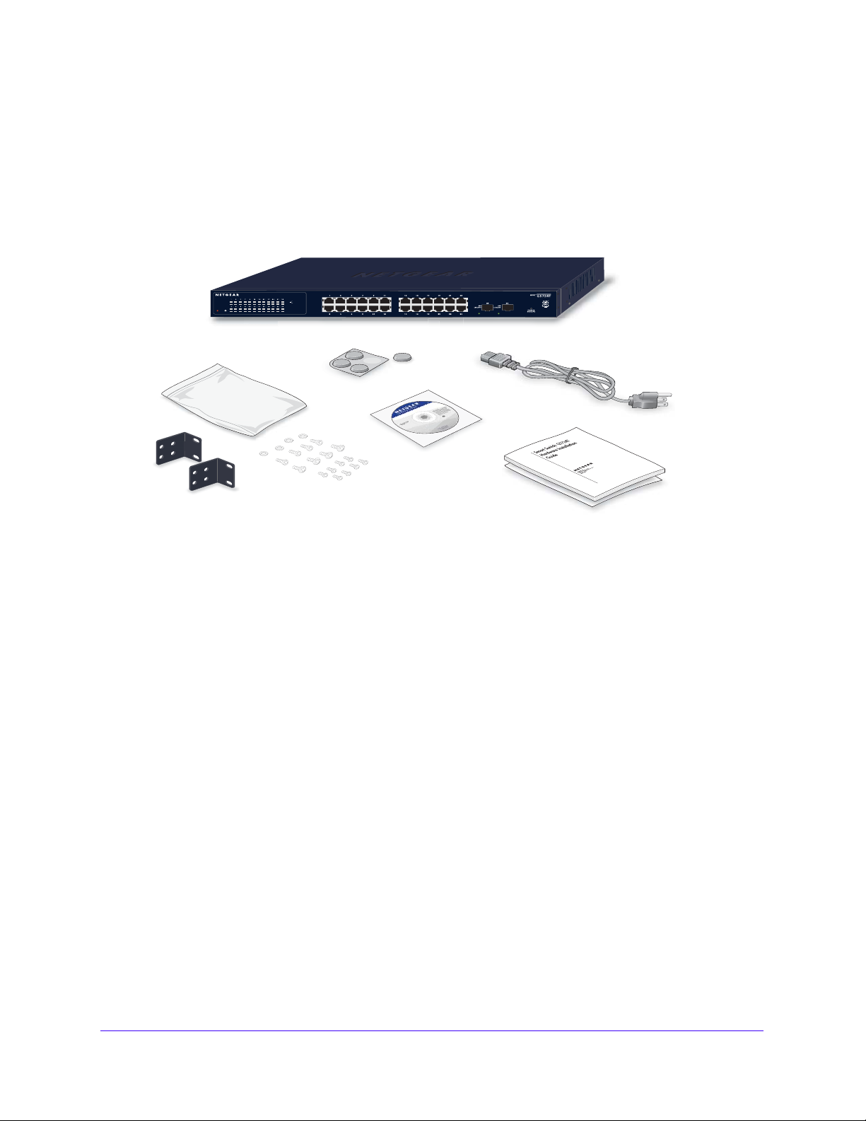
Package Contents
Figure 1 shows the package contents of the NETGEAR GS716Tv3 and GS724Tv4 and
GS748Tv5 Series Smart Switch.
Figure 1. Package Contents
Verify that the package contains the following:
• NE
• Rubber f
TGEAR Smart Switch
ootpads for tabletop installation
• Power cord
• Rack-mou
• Qu
ick Installation guide
• Smart
• W
arranty/Support Information Card
nt kit for installing the switch in a 19-inch rack
Switch Resource CD with Smart Control Center and User’s manual
If any item is missing or damaged, contact the
place of purchase immediately.
6

2. Physical Description
This chapter describes the NETGEAR Smart Switch hardware features. Topics
include:
• GS716T/GS724T Front Panel Configuration
• GS716T/GS724T Back Panel Configuration
• GS748T Front Panel Configuration
• GS748T Back Panel Configuration
• LED Designations
• Device Hardware Interfaces
2
7
GS716T , GS724T and GS748T Gigabit Smart Switch
System LEDs
SFP Ports
10/100/1000 Mbps Ethernet Ports
Reset
PWR
ProSafe 16 Port 10/100/1000Mbps Smart Switch
Link/ACT
SPD
Green(1000M)
Yellow(100M)
FDX
SPD
Link/ACT
FDX
System LEDs
SFP Ports
10/100/1000 Mbps Ethernet Ports
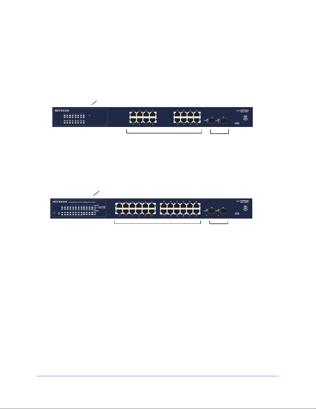
GS716T/GS724T Front Panel Configuration
The GS716T/GS724T has 16/24 10/100/1000 Mbps copper port and two dedicated 1000
Mbps SFP fiber ports. Every RJ-45 port is capable of sensing the line speed and negotiating
the operation duplex mode with the link partner automatically
Figure 2 illustrates the NETGEAR GS716T Smart Switch front panel:
Figure 2. GS716T Front Panel
Figure 3 illustrates the NETGEAR GS724T Smart Switch front panel:
Figure 3. GS724T Front Panel
The front panel contains the following:
6/24 RJ-45 connectors for 10/100/1000 Mbps auto sensing Gigabit Ethernet switching
• 1
ports.
• T
wo SFP slots for SFP modules supporting 1000 (1000BASE-SX/LX) Mbps SFP.
• Reset bu
• Recessed d
tton to restart the device.
efault reset button to restore the device back to the factory defaults.
• Port LEDs
• System LEDs
8

GS716T , GS724T and GS748T Gigabit Smart Switch
Power Connector
100-240V ~ 50 -60Hz
GS716T/GS724T Back Panel Configuration
Figure 4 illustrates the NETGEAR GS716T/GS724T Smart Switch back panel:
Figure 4. GS716T/GS724T Back Panel
The back panel contains the following:
• A 1
00-240VAC/50-60 Hz universal input, which is a standard AC power receptacle for
accommodating the supplied power cord.
9
 Loading...