

Page 1

M odular F ast Ethernet Switch
User‘s Guide
MODEL
FS
MODEL
FS
726
750
Page 2

ii
Trademarks
NETGEAR® is a registered trademark of NETGEAR, Inc. in the United States and other countries. All other
trademarks and registered trademarks are the property of their respective owners.
Statement of Conditions
In the interest of improving internal design, operational function,and/or reliability,NETGEAR reserves the
right to make changes to the products described in this document without notice. NETGEAR does not assume
any liability that may occur due to the use or application of the product(s) or circuit layout(s) described herein.
Certificate of the Manufacturer/Importer
It is hereby certified that the NETGEAR Model FS726 Modular Fast Ethernet Switch and Model FS750
Modular Fast Ethernet Switch have been suppressed in accordance with the conditions set out in the BMPTAmtsblVfg 243/1991 and Vfg 46/1992.The operation of some equipment (for example,test transmitters) in
accordance with the regulations may, however,be subject to certain restrictions. Please refer to the notes in
the operating instructions.
Federal Office for Telecommunications Approvals has been notified of the placing of this equipment on the
market and has been granted the right to test the series for compliance with the regulations.
Voluntary Control Council for Interference (VCCI) Statement
This equipment is in the first category (information equipment to be used in commercial and/or industrial
areas) and conforms to the standards set by the Voluntary Control Council for Interference by Data
Processing Equipment and Electronic Office Machines that are aimed at preventing radio interference in commercial and/or industrial areas.
Consequently, when this equipment is used in a residential area or in an adjacent area thereto,radio interference may be caused to equipment such as radios and TV receivers.
Federal Communications Commission (FCC) Compliance Notice:Radio Frequency Notice
This device complies with part 15 of the FCC Rules. Operation is subject to the following two conditions:
• This device may not cause harmful interference.
• This device must accept any interference received, including interference that may cause
undesired operation.
Note: This equipment has been tested and found to comply with the limits for a Class A digital device,
pursuant to part 15 of the FCC Rules.These limits are designed to provide reasonable protection against
harmful interference in a residential installation.This equipment generates, uses, and can radiate radio fre-
Page 3
iii
quency energy and,if not installed and used in accordance with the instructions, may cause harmful interference to radio communications. However,there is no guarantee that interference will not occur in a particular
installation.If this equipment does cause harmful interference to radio or television reception,which can be
determined by turning the equipment off and on,the user is encouraged to try to correct the interference by
one or more of the following measures:
• Reorient or relocate the receiving antenna.
• Increase the separation between the equipment and receiver.
• Connect the equipment into an outlet on a circuit different from that which the receiver is connected.
• Consult the dealer or an experienced radio/TV technician for help.
EN 55024 Declaration of Conformity
This is to certify that the NETGEAR Model FS726 Modular Fast Ethernet Switch and Model FS750
Modular Fast Ethernet Switch are shielded against the generation of radio interference in accordance with
the application of Council Directive 89/336/EEC, Article 4a. Conformity is declared by the application of EN
55024 Class A (CISPR 22).
Warning: This is a Class A product. In a domestic environment,this product may cause radio
interference, in which case the user may be required to take appropriate measures.
Canadian Department of Communications Radio Interference Regulations
These digital apparatuses (NETGEAR Model FS726 Modular Fast Ethernet Switch and Model FS750 Modular
Fast Ethernet Switch) do not exceed the Class A limits for radio-noise emissions from digital apparatus as set out in
the Radio Interference Regulations of the Canadian Department of Communications.
Règlement sur le brouillage radioélectrique du ministère des Communications
Ces appareils numériques (NETGEAR Model FS726 Modular Fast Ethernet Switch et Model FS750
Modular Fast Ethernet Switch) respectent les limites de bruits radioélectriques visant les appareils
numériques de classe A prescrites dans le Règlement sur le brouillage radioélectrique du ministère des
Communications du Canada.
!
Page 4

iv
Customer Support
For assistance with installing and configuring your NETGEAR system or with questions or problems
following installation:
• Check the NETGEAR Web page at http://www.NETGEAR.com.
• Call Technical Support in North America at 1-888-NETGEAR.Our technicians are standing by to assist
you 24 hours a day, 7 days a week.If you are outside North America,please refer to the phone numbers
listed on the Support Information Card that shipped with your switch.
• E-mail Technical Support at support@NETGEAR.com.
Defective or damaged merchandise can be returned to your point-of-purchase representative.
Internet/World Wide W eb
NETGEAR maintains a World Wide Web home page that you can access at the uniform resource locator
(URL) http://www.NETGEAR.com.A direct connection to the Internet and a Web browser such as Internet
Explorer or Netscape are required.
Page 5

vContents
CONTENTS
CHAPTER 1
Introduction 1-1
Description 1-1
Features 1-2
Key Features 1-2
Additional Features 1-3
Package Contents 1-5
CHAPTER 2
Physical Description 2-1
Front and Back Panels 2-1
10/100 Mbps RJ-45 Ports 2-3
LED Mode Button and LED Descriptions 2-4
Module Bays 2-5
Auto Uplink 2-5
Reset Button 2-7
CHAPTER 3
Applications 3-1
Desktop Switching 3-1
Segment Switching and Bridging from 10 Mbps to 100 Mbps 3-2
Media Compatibility and Conversion 3-2
CHAPTER 4
Installation 4-1
Preparing the Site 4-2
Installing the Switch 4-3
Installing the Switch on a Flat Surface 4-3
Installing the Switch in a Rack 4-3
Connecting Devices to the Switch 4-4
Using Gigabit Ethernet Modules 4-5
Checking the Installation 4-6
Applying AC Power 4-6
Page 6

contents vi
CHAPTER 5
Troubleshooting Information 5-1
Additional Troub leshooting Suggestions 5-3
Network Adapter Cards 5-3
Configuration 5-3
Switch Integrity 5-3
Auto Negotiation 5-3
APPENDIX A
Technical Specifications A-1
Network Protocol and Standards Compatibility A-1
Data Rate A-1
Interface A-1
Performance Specifications A-2
Bandwidth A-2
Electrical Specifications A-3
Power Consumption A-3
Physical Specifications A-3
Environmental Specifications A-3
Electromagnetic Emissions A-4
Electromagnetic Susceptibility A-4
Safety Agency Approvals A-4
APPENDIX B
Connector Pin Assignments B-1
RJ-45 Plug and RJ-45 Connector B-1
Duplex SC Plug and Duplex SC Connector B-3
Page 7

viicontents
APPENDIX C
Cabling Guidelines C-1
Fast Ethernet Cable Guidelines C-1
Category 5 Cable C-2
Category 5 Cable Specifications C-3
Twisted Pair Cables C-3
Patch Panels and Cables C-5
Using 1000BASE-T Gigabit Ethernet over Category 5 Cable C-5
Overview C-5
Cabling C-6
Length C-6
Return Loss C-6
Near End Crosstalk (NEXT) C-7
Patch Cables C-7
Conclusion C-7
Fiber Optic Cables C-8
Fiber Cable Specifications C-8
Gigabit Cable Guidelines C-8
INDEX I-1
FIGURES
Page 8

figures viii
Figure 1-1. Package Contents 1-5
Figure 2-1. Front and Back Panels of the FS726 Switch 2-2
Figure 2-2. Front and Back Panels of the FS750 Switch 2-3
Figure 2-3. Creating Redundant Paths between
Network Devices (Example 1) 2-6
Figure 2-4. Creating Redundant Paths between
Network Devices (Example 2) 2-6
Figure 3-1. Example of Desktop Switching 3-1
Figure 3-2. Example of Segment Switching and Bridging 3-2
Figure 3-3. Example of Media Compatibility
and Conversion 3-3
Figure 4-1. Attaching Mounting Brackets 4-3
Figure 4-2. Connecting Devices to the Switch 4-4
Figure B-1. RJ-45 Plug and RJ-45 Connector
with Built-in LEDs B-1
Figure B-2 Duplex SC Cconnector and Duplex SC Plug B-3
Figure C-1. Straight-Through Twisted-Pair Cable C-4
Figure C-2. Crossover Twisted-Pair Cable C-4
Figure C-3. Category 5 UTP Cable with
Male RJ-45 Plug at Each End C-5
TABLES
Page 9

ixtables
Table 1-1. Key Features 1-2
Table 2-1. Front Panel LEDs 2-4
Table 4-1. Site Requirements 4-2
Table 5-1. Troubleshooting Information 5-1
Table B-1. 10/100 Mbps RJ-45 Plug and
RJ-45 Connector Pin Assignments B-2
Table B-2. 100/1000 Mbps RJ-45 Plug and
RJ-45 Connector Pin Assignments B-2
Table C-1. Electrical Requirements
of Category 5 Cable C-3
Table C-2. Electrical Requirements of
Fiber Optic Cable C-8
Table C-3. Gigabit Cable Guidelines C-8
Page 10

1-1introduction
CHAPTER 1: INTRODUCTION
This installation guide describes the NETGEAR FS726 and FS750 Modular Fast
Ethernet Switches.
NETGEAR’s FS726 and FS750 are expandable, high-performance, IEEE-compliant
network switches designed for users who require a large number of ports and want the
high-speed capability of 10/100 switching to eliminate bottlenecks, boos t performance,
and increase productivity.Both switches are designed with front module bays that will
accommodate either copper gigabit modules or fiber gigabit modules for high-speed
connection to a server or your network backbone. Built-in modularity gives you the flexibility to buy according to your immediate needs, then add to your system later.You can
purchase the optimal combination of copper and fiber gigabit modules for your network
– both the same or one of each, as either will function in each module bay.To simplify
installation,both switch models are shipped ready for use, with no configuration
required. Everything necessary for setup comes in the box.
This chapter provides the following information:
• Description
• Features
• Package contents
Description
NETGEAR’s FS726 and FS750 Modular Fast Ethernet Switches are flexible,powerful,
and easy-to-use network solutions.Both switches have two front panel module bays that
can be used with gigabit uplinks to create a high-performance backbone connection.
Each module bay accepts either a copper Gigabit Ethernet module (1000BASE-T,
Page 11

introduction 1-2
NETGEAR Model AG711T) or a fiber Gigabit Ethernet module (1000BASE-SX,
NETGEAR Model AG711F). (Modules are not included with the switches.) With the
advantage of this modularity you can:
• Connect switches to each other with high-speed links
• Link up to high-speed servers
• Connect fiber and copper networks
The NETGEAR FS726 Switch provides 24 shielded RJ-45 network ports,while the
NETGEAR FS750 Switch provides 48 shielded RJ-45 network ports. All RJ-45 por ts
on the FS726 and FS750 Switches automatically negotiate to the highest speed,
making the switches ideal for environments that have a mix of Ethernet and Fast
Ethernet devices.In addition, all 10/100 Mbps por ts operate in half- or full-duplex
mode,increasing the maximum bandwidth of each connection up to 20 Mbps or 200
Mbps, respectively. Both switch models support au tomatic address learning and IEEE
802.3x-compliant flow control to ensure optimal packet reliability.
The FS726 and FS750 Switches can be free-standing or rack mounted in a wiring
closet or equipment room.
Features
The following sections describe the characteristics of NETGEAR’s FS726 and
FS750 Switches.
Key Features
Table 1-1 summarizes the key features of the FS726 and FS750 Switches.
Table 1-1. Key Features:
Feature FS726 Switch FS750 Switch
Number of 10/100 Mbps RJ-45 ports per switch: 24 48
Number of module bays per switch: 2 2
Page 12

1-3introduction
Additional Features
The FS726 and FS750 Switches share the following features:
• Uplink adaptability for either copper gigabit or fiber gigabit modules
• Auto UplinkTMto automatically configure the RJ-45 ports for use with either
straight-through or crossover cables to make the right connection
• Non-blocking,wire-speed filtering and forwarding of the traffic on all ports
• Scalability to meet your growing network needs, enabling performance to keep pace
with port density
• High-speed bandwidth over uplink connections
• Easy Plug-and-Play installation with no software to configure,for quick and easy
connection to new or existing 10 and 100 Mbps users and services
• Store-and-forward intelligent processing to remove erroneous packets from
the network
• Automatic address-learning function to build the packet-forwarding information table.
The table contains up to 8,000 media access control (MAC) addresses (that is, the
switch can support networks with as many as 8,000 devices).
• Link speed auto-sensing (10 or 100 Mbps) and duplex mode auto-s ensing (half- or
full-duplex) to optimize connectivity and allow companies to migrate to Fast Ethernet
one port at a time
• Full-duplex mode to double throughput of point-to-point connections by enabling
individual ports to transmit and receive data concurrently
• IEEE 802.3x-compliant flow control to prevent dropped packets due to network
back-ups and bottlenecks
Page 13

introduction 1-4
• Compliance with the IEEE802.3i Ethernet, IEEE802.3u Fast Ethernet standards,
IEEE802.3ab Gigabit Ethernet, and IEEE802.3z Gigabit Ethernet.
• LED indicators to show link, speed, ac tivity,collision, and duplex for switch status
and troubleshooting.
• Rack Mount Kit for installing the switch in a standard 19-inch equipment rack
Page 14
1-5introduction
Package Contents
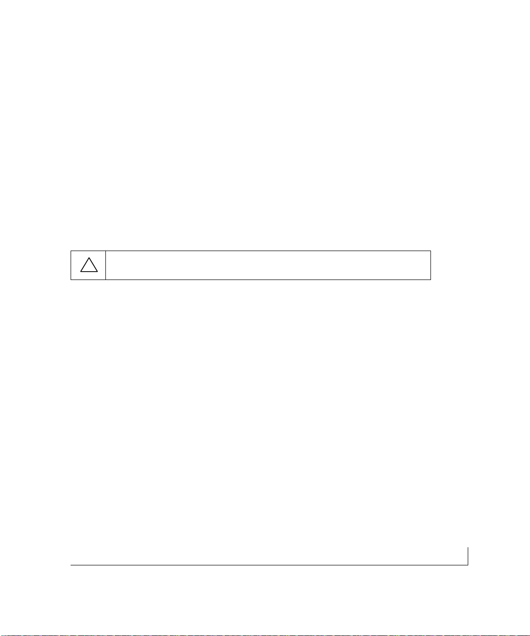
Figure 1-1 shows the package contents of the FS726 and FS750 switches.
Figure 1-1.Package Contents
Verify that your package contains the following:
• FS726 or FS750 Switch
• Rubber footpads for tabletop installation
• Power cord
• Rack-mount kit for installing the switch in a 19-inch rack
• NETGEAR FS726 and FS750 Modular Fast Ethernet Switch User’s Guide
• Support Information Card
• Warranty & Owner Registration Card
If any item is missing or damaged,contact your place of purchase immediately.
Rubber
footpads
AC
power
cord
Rack-mount
kit
Installation Guide
Warranty
Owner Registration Card
Support Information Card
Model FS726 or Model FS750 Switch
(Model FS726 shown)
Page 15

2-1physical description
CHAPTER 2: PHYSICAL DESCRIPTION
This chapter describes the hardware features of the FS726 and FS750 Switches.
Topics include:
• Front and back panels
• 10/100 Mbps RJ-45 ports
• LED Mode button and LEDs
• Module bays (for copper or fiber Gigabit Ethernet modules)
• Auto Uplink
• Reset button
Front and Back Panels
Figure 2-1 shows the key components on the front and back panels of the FS726
Switch. Figure 2-2 shows the key components on the front and back panels of the
FS750 Switch.
The front panel of each switch contains a reset button, an LED Mod e push button for
alternating LED readout categories, Link LEDs, Mode LEDs, RJ-45 jacks, and two
module bays for installing Gigabit Ethernet modules. Both the FS726 Switch and the
FS750 Switch support Auto Uplink technology,eliminating the need for a
Normal/Uplink push button.
The back panel of each switch has fans for cooling,and a standard AC power
receptacle for accommodating the supplied power cord.
Page 16
physical description 2-2
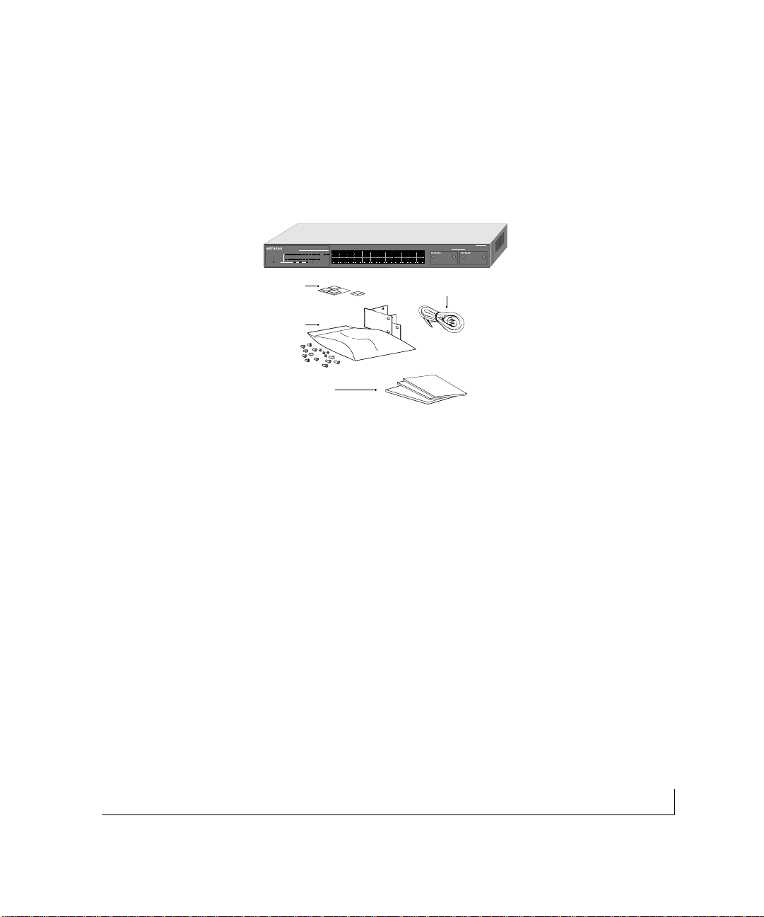
Figure 2-1.Front and Back Panels of the FS726 Switch
10/100 Mbps
ports
Module Bays
LED Mode
Button
Reset
Button
Fan
Power
Receptacle
Front Panel of the Model FS726 Switch
Rear Panel of the Model FS726 Switch
Link LEDs Mode LEDs
Power
LED
Page 17

2-3physical description
Figure 2-2.Front and Back Panels of the FS750 Switch
10/100 Mbps RJ-45 Ports
As Figures 2-1 and 2-2 show,the FS726 Switch has 24 RJ-45 ports, while the FS750
Switch has 48 RJ-45 ports.These are auto-sensing 10/100 Mbps ports: when you
insert a cable into an RJ-45 port, the switch automatically detects the maximum speed
(10 or 100 Mbps) and duplex mode (half- or full-duplex) of the attached device,and
displays this information using the front panel 100 Mbps and FDX LEDs for that port
(LEDs are described in the next section).The 10/100 Mbps ports suppor t only unshielded twisted-pair (UTP) cable terminated with an 8-pin RJ-45 plug.
10/100 Mbps
ports
Front Panel of the Model FS750 Switch
Rear Panel of the Model FS750 Switch
Module Bays
LED Mode
Button
Reset
Button
Power
LED
Link LEDs
Mode LEDs
Page 18

physical description 2-4
LED Mode Button and LED Descriptions
LEDs on the front panels of the FS726 and FS750 Switches provide a quick and
accurate display of port operation. Users can clearly identify the status of each port
for link and by toggling the LED Mode button through the associated categories speed,
activity, collision,and duplex mode .
Table 2-1 summarizes the LEDs on the FS726 and FS750 Switches.A detailed
description of the LEDs follows the table.
Table 2-1. Front Panel LEDs
Label Color Activity Description
Power Green On Power is supplied to the switch.
Off Power is disconnected
Link Green On Port has a valid link connection.
Off A valid link has not been established on the port.
Mode in: Max Spd
10/100 Mbps Port Green On Port has made a 100 Mbps connection.
Off Port has made a 10 Mbps connection.
Module Bay Port Green On Port has a valid 1000 Mbps (1 Gbps) link connection
Off A valid link has not been established on the port.
Mode in: Activity /
Collision Green Blinking Data transmission is occurring on the port.
Yellow Blinking Data collision is occurring on the port. The rate at
which this LED blinks corresponds to the number of
collisions. When a collision occurs, the connected
device pauses and transmits again after waiting a
specified time.
Mode in: FDX Green On Port is operating in full-duplex mode.
Yellow On Port is operating in half-duplex mode.
Page 19

2-5physical description
Module Bays
Two module bays on both switches allow you to upgrade as you go,whether you need
gigabit uplink or additional port capacity.Each module bay will accept either a copper
Gigabit Ethernet module (1000BASE-T, NETGEAR Model AG711T) or a fiber Gigabit
Ethernet module (1000BASE-SX,NETGEAR Model AG711F) for high-speed connection to a server, to connect fiber and copper networks,or to extend your network backbone with high-speed links.
Auto Uplink
To simplify the procedure for attaching devices,all RJ-45 ports on the FS726 and
FS750 Switches support Auto Uplink. This technology allows you to attach devices to
the RJ-45 ports using either straight-through or crossover cables.When you insert a
cable into the switch’s RJ-45 port, the switch automatically:
• Senses whether the cable is a straight-through or crossover cable, and
• Determines whether the link to the attached device requires a "normal" connection
(such as when connecting the port to a PC) or an "uplink" connection (such as when
connecting the port to a router, switch,or hub).
After detecting this information,the switch automatically configures the RJ-45 port to
enable communications with the attached device,without requiring user intervention. In
this way, the Auto Uplink technology compensates for setting uplink connections,while
eliminating concern about whether to use crossover or straight-through cables when
attaching devices.
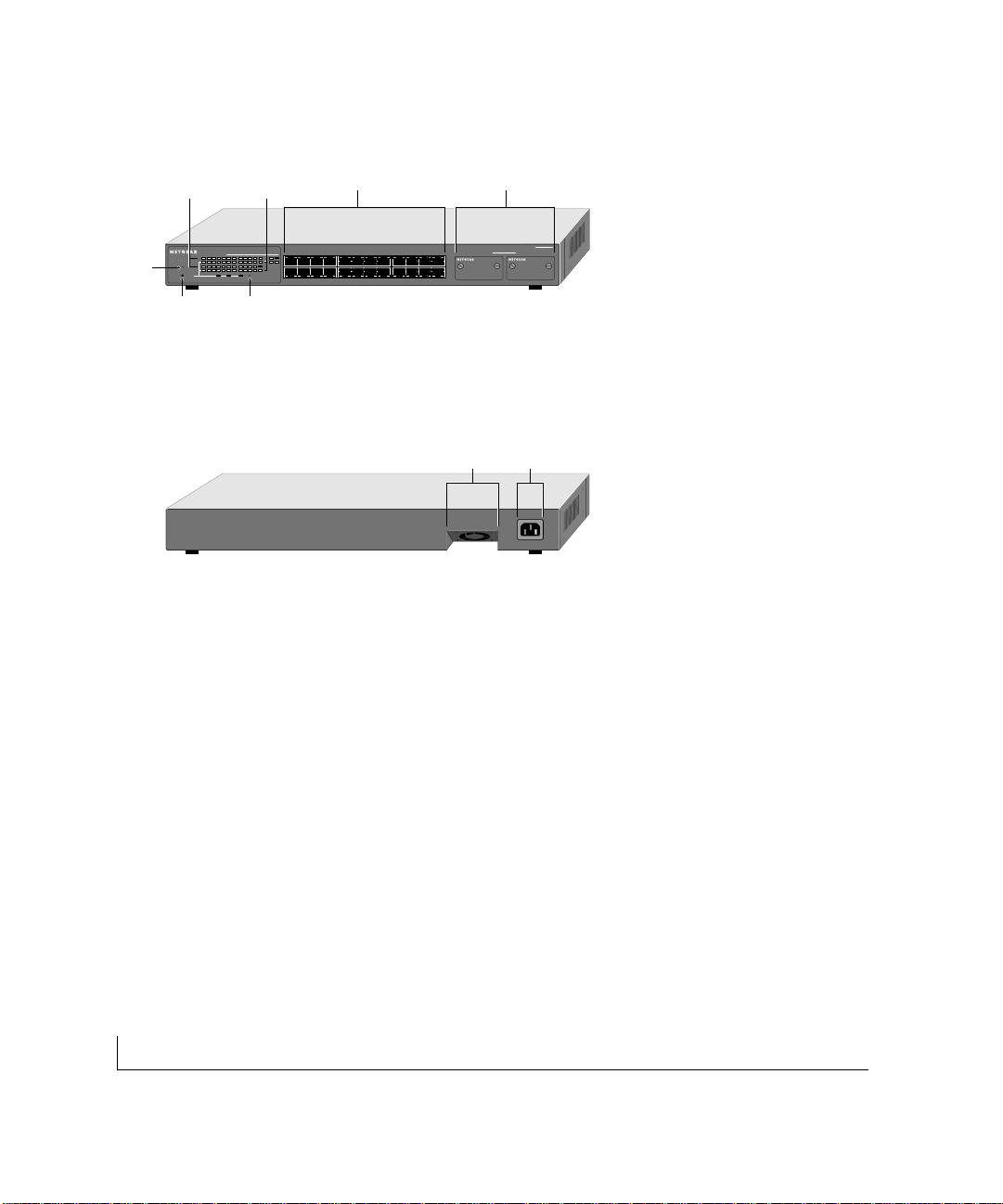
Note: Using Auto Uplink to create multiple active paths between any two
network devices can cause undesirable loops in the network, resulting in an
endless broadcast traffic that disables your network.Loops occur when there are
alternate routes between two network devices. In Figure 2-3, for example, a
loop is created by connecting two RJ-45 ports on an FS726 Switch to a
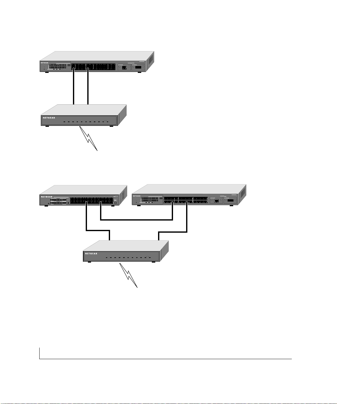
router containing a 4-port switch. Figure 2-4 shows another scenario where a
router with a 4-port switch connects to a hub and to a FS726 Switch; the hub
and switch, in turn,connect back to the same router, creating multiple active
paths between all three devices.
Page 20
physical description 2-6
Model FS726 Switch
EN524 Hub
FR314 Router
Model FS726 Switch
FR314 Router
Figure 2-3.Creating Redundant Paths between Network Devices (Example 1)
Figure 2-4.Creating Redundant Paths between Network Devices (Example 2)
Page 21

2-7physical description
Reset Button
A reset button is located on the front panels of the FS726 and FS750 Switches.The
button allows you to reinitialize the switches after you either insert or remove a module
from a module bay.To activate the Reset button, insert a small wire, such as a paper
clip, into the hole and gently push. As the switch reinitializes,all of the LEDs will
extinguish, then light up for approximately one second during the self-test, and then
return to their normal state.The switch will then operate as normal with the new
bay configuration.
Page 22

3-1applications
CHAPTER 3:APPLICATIONS
The FS726 and FS750 Switches are designed to provide flexibility in configuring your
network connections.Both switches can be used as stand-alone devices or used with 10
Mbps hubs, 100 Mbps hubs, or 10/100 Mbps switches.This chapter shows how the
FS726 and FS750 Switches can be used in various network environments.
Topics include:
• Desktop switching
• Segment switching and bridging from 10 Mbps to 100 Mbps
• Media compatibility and conversion
Desktop Switching
The FS726 and FS750 Switches can be used as desktop switches to build a small
network that enables users to have 1000 Mbps access to a file server. A full-duplex
adapter card installed in the server can provide 2000 Mbps full-duplex connection.
Figure 3-1.Example of Desktop Switching
1000 Mbps
100 Mbps
10 Mbps
Model FS726
Switch
Server
Model FS750
Switch
Server
Page 23

applications 3-2
Segment Switching and Bridging from 10 Mbps to 100 Mbps
The FS726 and FS750 Switches can be used to segment a network into multiple connected pieces to increase overall bandwidth and throughput. Both switch mod els can
segment networks that are built with the NETGEAR DS508 and EN516 hubs,and can
act as bridges connecting traditional 10BASE-T Ethernet networks to 100BASE-TX
Fast Ethernet networks.
Figure 3-2.Example of Segment Switching and Bridging
Media Compatibility and Conversion
The FS726 and FS750 Switches are ideal for a mixed media environment.Both switches feature two front panel module bays that can be easily installed with one or two fiber
Gigabit Ethernet modules, one or two copper Gigabit Ethernet modules,or one gigabit
module of each type,providing optimal flexibility for high-speed connection to a server
or your network backbone.
Model FS726 Switch
Model EN516
Hub
Model FR314
Router
Model DS508
Hub
Page 24

3-3applications
Model FS726
Figure 3-3.Example of Media Compatibility and Conversion
Model FS518
MODEL
FS518T
18
10/100Mbps
PORT
Fast Ethernet Switch
with Gigabit Ports
1234567817
Power
10
9
Green=FDX,Yellow+COL
11
Green = FDX,Yellow = COL
Activity
1
00M 10M
Activity
14 15 1613 18
12
9
45
13 16 18
12
Switching
8
17
On = Link
1000M 100M
Normal/Uplink
PORT
9
10/100Mbps
Power
Fast Ethernet Switch
234
1
Model FS509
Rx/Tx
6785 9
Green = FDX, Yellow = COL
1
234 567 8
100M 10M
1
MODEL
Ethernet
On = Link
Normal/Uplink
FS509
Tx Rx
1000M Link
Page 25

4-1installation
CHAPTER 4: INSTALLATION
This chapter describes the installation procedures for the NETGEAR FS726 and
FS750 Switches.Topics include:
• Preparing the site
• Installing the switch
• Connecting devices to the switch
• Checking the installation
• Applying AC power
Page 26

installation 4-2
Preparing the Site
Before you install your switch, be sure your operating environment meets the operating
environment requirements in Table 4-1.
Table 4-1. Site Requirements
Characteristics Requirements
Mounting
Desktop installations: Provide a flat table or shelf surface.
Rack-mount installations: Use a 19-inch (48.3-centimeter) EIA standard equipment rack that is
grounded and physically secure. You also need the rack-mount kit supplied
with your switch.
Access Locate the switch in a position that lets you access the front panel RJ-45
ports, view the front panel LEDs,and access the rear-panel stacking port(s)
and power connector.
Power source Provide a power source within 6 feet (1.8 meters) of the installation
location.Power specifications for the switches are shown in Appendix A.Be
sure the AC outlet is not controlled by a wall switch, which can accidentally
turn off power to the outlet and the switch.
Environmental
Install the switch in a dry area, with ambient temperature between 0 and
Temperature: 40ºC (32 and 104ºF). Keep the switch away from heat sources such as
direct sunlight,warm air exhausts, hot-air vents,and heaters.
Operating humidity: The installation location should have a maximum relative humidity of
90%, non-condensing.
Ventilation: Do not restrict airflow by covering or obstructing air inlets on the sides of
the switch. Keep at least 2 inches (5.08 centimeters) free on all sides for
cooling.Be sure there is adequate airflow in the room or wiring closet where
you intend to install the switch.
Operating conditions: Keep the switch at least 6 ft (1.83 m) away from nearest source of electro
magnetic noise,such as a photocopy machine.
After confirming that your site meets the requirements in Table 4-1, you are ready to
install the switch.
Page 27

4-3installation
Installing the Switch
You can install the NETGEAR FS726 and FS750 Switches on a flat surface or in a
standard 19-inch rack.
Installing the Switch on a Flat Surface
1. The switch ships with four self-adhesive rubber footpads. Affix one rubber footpad
on each of the four concave spaces on the bottom of the switch. The rubber
footpads cushion the switch against shock/vibrations.
Installing the Switch in a Rack
To install the FS726 or FS750 Switch in a rack,use the following procedure (and refer
to Figure 4-1).To perform this procedure, you need the 19-inch rack-mount kit supplied
with your switch.
1. Attach the supplied mounting brackets to the side of the switch.
2. Insert the screws provided in the rack-mount kit through each bracket and into the
bracket mounting holes in the switch.
3. Tighten the screws with a #1 Phillips screwdriver to secure each bracket.
4. Align the mounting holes in the brackets with the holes in the rack, and insert two
pan-head screws with nylon washers through each bracket and into the rack.
5. Tighten the screws with a #2 Phillips screwdriver to secure the switch in the rack.
6. Proceed to "Connecting Devices to the Switch."
M
O
D
E
L
Figure 4-1.Attaching Mounting Brackets
Page 28

installation 4-4
Connecting Devices to the Switch
The following procedure describes how to connect devices to the switch’s RJ-45 ports.
When attaching devices to an FS726 or an FS750,the switch’s support for Auto
Uplink technology allows you to attach devices using either straight-through or
crossover cables (for more information about Auto Link‘ technology, refer to "Auto
Uplink " on page 12).
7. Connect each device to an RJ-45 network port on the switch’s front panel (see
Figure 4-2). Us e Category 5 (Cat5) unshielded twisted-pair (UTP) cable terminated
with an RJ-45 connector to make these connections.
Figure 4-2.Connecting Devices to the Switch
Note: Ethernet specifications limit the cable length between the switch and the
attached device to 100 m (328 ft).
Front Panel of the Model FS726 or Model FS750 Switch
(Model FS726 shown)
Page 29

4-5installation
Using Gigabit Ethernet Modules
The modularity of the FS726 and 750 Switches provides you with a highly adaptable
network..You not only can configure your network for copper and/or fiber gigabit
uplinks,but you also can opt to expand your network gradually and affordably, as needed.
Installing a Gigabit Ethernet module:
a. Unscrew and remove the module cover plate.
b. Insert the module into the slot, pressing firmly to seat the module.
c. Tighten the module screws.
d. Press the reset button if the power has remained on throughout the installation of
the gigabit modules.
Page 30

installation 4-6
Checking the Installation
Before you apply power:
• Inspect the equipment thoroughly.
• Verify that all cables are installed correctly.
• Check cable routing to make sure cables are not damaged or create a safety hazard.
• Be sure all equipment is mounted properly and securely.
Applying AC Power
The switches do not have an ON/OFF switch;the only method of applying or removing
AC power is by connecting or disconnecting the power cord.Before you connect the
power cord,select an AC outlet that is not controlled by a wall switch, which can turn
off power to the switch.After you select an appropriate outlet, us e the following
procedure to apply AC power.
8. Connect the female end of the supplied AC power adapter cable to the power outlet
on the back of the switch
9. Connect the 3-pronged end of the AC power adapter cable to a grounded 3-pronged
AC outlet.
When you apply power:
• The green Power LED on the switch’s front panel goes on.
• The green Link LED on each connec ted RJ-45 por t goes on.
If the green Power LED does not go on,check that the power cable is plugged in
correctly and that the power source is good. If this does not resolve the problem,refer
to Chapter 5,Troubleshooting.When power is applied,the switch conducts a power-on
self-test (POST) to verify operation.After the switch passes the POST, it is functional
and ready to pass data.
Page 31

4-7installation
Page 32

5-1troubleshooting
CHAPTER 5:TROUBLESHOOTING
This chapter provides guidance in troubleshooting the NETGEAR FS726 and FS750
Switches. Information includes:
• Troubleshooting information table
• Additional troubleshooting suggestions
Troubleshooting Chart
Table 5-1 lists symptoms,causes, and solutions of possible problems.
Table 5-1.Troubleshooting Chart
Symptom Cause Solution
Power LED is off. No power is received Check the power cord connections
for the switch at the switch.and the
connected device.
Make sure all cables used are
correct and comply with Ethernet
specifications.
Link LED is off Port connection is not working Check the crimp on the connectors
or intermittnet. and make sure that the plug is
properly inserted and locked into the
port at both the switch and the
connecting device.
Make sure all cables used are
correct and comply with Ethernet
specifications.See Appendix C.
Check for a defective adapter card,
cable,or por t by testing them in an
alternate environment where all
products are functioning.
Page 33

troubleshooting 5-2
Symptom Cause Solution
Link LED is off for a port There is a problem with this Make sure the cable is attached
that has a connection. connection. securely at both ends.
Make sure the cable is not damaged.
Check that the device being connected
to is powered on and operating
correctly.
If the connection is to a workstation,
make sure the workstation’s network
interface is installed and configured
correctly.
File transfer is slow or Half- or full-duplex setting on Make sure the attached device is set to
performance degradation the switch and the connec ted auto negotiate.
is a problem. device are not the same.
A segment or device is One or more devices are not Verify that the cabling is correct. Be
not recognized as part properly connected,or sure all connectors are securely
of the network. cabling does not meet positioned in the required ports.
Ethernet guidelines. Equipment may have been accidentally
disconnected.
ACT LED is blinking Collisions are occurring Some collisions are normal when
yellow excessively. on the connected segment. the connection is operating in
half-duplex mode.
Duplex modes are mismatched. Recheck the settings of the device
attached to the RJ-45 port. Make
sure the attached device is set to
auto negotiate.
ACT LED is flashing A network loop (redundant path) Break the loop by ensuring that there
continuously on all has been created is only one path from any networked
connected ports and the (see Figures 2-3 and 2.4). device to any other networked device.
network is disabled
Page 34

5-3installation
Additional T roubleshooting Suggestions
If the suggestions in Table 5-1 do not resolve your problem,refer to the troubleshooting
suggestions in this section.
Network Adapter Cards
Make sure the network adapter cards installed in the PCs are in working condition and
the software driver has been installed.
Configuration
If problems occur after altering the network configuration, res tore the original connections
and determine the problem by implementing the new changes, one s tep at a time. Make
sure that cable distances,repeater limits, and other physical aspects of the installation
do not exceed the Ethernet limitations.
Switch Integrity
If required, verify the integrity of the switch by resetting the switch.To reset the switch,
remove AC power from the switch and then reapply AC power. If the problem continues,
contact NETGEAR technical support. In North America,call 1-888-NETGEAR. If you
are outside of North America, please refer to the support information card included
with your product.
Auto Negotiation
The 10/100 Mbps ports negotiate the correct duplex mode and speed if the device at
the other end of the link supports au to negotiation. If the device does not support au to
negotiation,the switch only determines the speed correctly and the duplex mode
defaults to half-duplex.
Page 35

A-1technical specifications
APPENDIX A:TECHNICAL SPECIFICATIONS
This appendix provides technical specifications for the NETGEAR FS726 or
FS750 Switches.
Network Protocol and Standards Compatibility
ISO/IEC 802-3i 10BASE-T
IEEE 802.3u 100BASE-TX
IEEE 802.3ab 1000BASE-T
IEEE 802.3z 1000BASE-SX
IEEE 802.3x Flow Control
Data Rate
10 Mbps differential Manchester encoded,IEEE 802.3
100 Mbps with 4B/5B encoding and MLT-3 physical interface for 100BASE-TX
1000 Mbps with 8B/10B encoding PAM-5 physical interface for 1000BASE-T
Interface
RJ-45 connector for 10BASE-T, 100BASE-TX Fast Ethernet,and 1000BASE-T
Gigabit Ethernet 1000 Mbps Duplex SC fiber connector for 62.5/125 or 50/125
multimode fiber (1000BASE-SX)
Page 36

technical specifications A-2
Performance Specifications
Frame filter rate: 14,800 frames/second, maximum on 10 Mbps port
(64B packets)
148,000 frames/second, maximum on 100 Mbps port
(64B packets)
1,480,000 frames/second, maximum on 1000 Mbps port
(64B packets)
Frame forward rate: 14,800 frames/second, maximum on 10 Mbps port
(64B packets)
148,000 frames/second, maximum on 100 Mbps port
(64B packets)
1,480,000 frames/second, maximum on 1000 Mbps port
(64B packets)
10/100 buffer memory: 8 MB for 16 ports
Gigabit buffer memory: 2 BM per port
Forwarding modes: Store-and-forward
Network latency: Less than 80 microseconds for 64-byte frames in store-and-
forward mode for 10 Mbps to 100 Mbps transmission
Address database size: 8,000 media access control (MAC) addresses per system
Addressing: 48-bit MAC address
Acoustic noise: FS726 FS750
(ANSI-S10.12) 45 dB 52dB
FS726 FS750
Heat Dissipation: 18.99 Btu/hr 12.06 Btu/hr
FS726 FS750
Bandwidth: 5 Gbps 8 Gbps
Page 37

A-3technical specifications
Electrical Specifications
FS726 FS750
Power Consumption: 40W maximum 60W maximum
Physical Specifications
FS726 FS750
Dimensions: W 440 mm (17.3") W 440 mm (17.3")
D 205 mm (8.1") D 205 mm (8.1")
H 43 mm (1.6") H 86 mm (3.4")
Weight: 3.2 Kg (7.0 lbs) 4.3 Kg (9.5 lbs)
Environmental Specifications
Operating temperature: 0 to 40°C
Storage temperature: -32 to 104°C
Operating humidity: 90% maximum relative humidity,noncondensing
Storage humidity: 95% maximum relative humidity, noncondensing
Operating altitude: 10,000 ft (3,000 m) maximum
Storage altitude: 10,000 ft (3,000 m) maximum
Page 38

technical specifications A-4
Electromagnetic Emissions
Meets requirements of:
CE mark,commercial
FCC Part 15,Subpart B, Class A
EN 55024 (CISPR 22),Class A
VCCI Class 1A
C-tick
Electromagnetic Susceptibility
CE mark,commercial
Electrostatic discharge (ESD): IEC 801-2,Level 2/3
Radiated electromagnetic field: IEC 801-3, Level 2
Electrical fast transient/burst: IEC 801-4, Level 2
Electrical surge: IEC 801-5, Level 1/2
Safety Agency Approvals
CE mark,commercial
UL/cUL listed (UL 1950)
CSA certified (CSA 22.2 #950)
TUV licensed (EN 60 950)
Page 39
B-1connector pin assignments
APPENDIX B: CONNECTOR PIN ASSIGNMENTS
This appendix provides information about the RJ-45 plug and the RJ-45 connector used
for the NETGEAR FS726 and FS750 Switches.
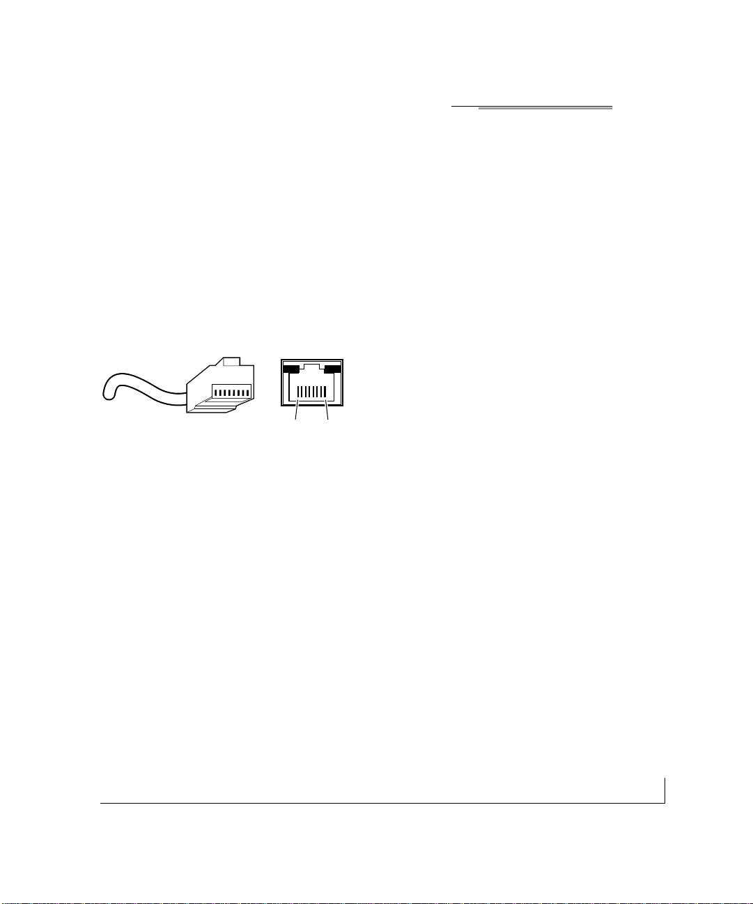
RJ-45 Plug and RJ-45 Connector
In a Fast Ethernet network, it is important that all 100BASE-T certified Category 5
cabling use RJ-45 plugs.The RJ-45 plug accepts 4-pair UTP or shielded twisted-pair
(STP) 100 ohm cable and connects into the RJ-45 connector.The RJ-45 connector is
used to connect stations, hubs, and switches through UTP cable;it supports 10 Mbps,
100 Mbps, or 1000 Mbps data transmission.
Figure B-1 shows the RJ-45 plug and RJ-45 connector.
Figure B-1.RJ-45 Plug and RJ-45 Connector with Built-in LEDs
12345678
18
Key:
1 to 8 = pin numbers
711EA
Page 40

connector pin assignments B-2
Table B-1 lists the pin assignments for the 10/100 Mbps RJ-45 plug and the
RJ-45 connector.
Table B-1. 10/100 Mbps RJ-45 Plug and RJ-45 Connector Pin Assignments
Pin Normal Assignment Uplink Assignment
1 Input Receive Data + Output Transmit Data +
2 Input Receive Data – Output Transm it Data –
3 Outpu t Transmit Data + Input Receive Data +
6 Output T ransm it Data – Input Receive Data –
4, 5,7,8 Internal termination,not used for data transmission
Table B-2 lists the pin assignments for the 10/100/1000 Mbps RJ-45 plug and the
RJ-45 connector.
B-2. 10/100/1000 Mbps RJ-45 Plug and RJ-45 Connector Pin Assignments
Pin Channel Description
1 A Rx/Tx Data +
2 Rx/Tx Data
3 B Rx/Tx Data +
6 Rx/Tx Data
4 C Rx/Tx Data +
5 Rx/Tx Data
7 D Rx/Tx Data +
8 Rx/Tx Data
Page 41

B-3connector pin assignments
Duplex SC Plug and Duplex SC Connector
The duplex SC connector connects s tations, hubs, and switches that support the
1000BASE-SX fiber interface. Each fiber link needs a clearly defined,external
crossover. In other words, the transmit port of one interface must be wired to the
receive port of the opposite interface and vice versa. Fiber cables must be connec ted in
this manner to transmit and receive data.
The duplex SC connector and duplex SC plug are illustrated in Figure B-2.
Figure B-2.Duplex SC Connector and Duplex SC Plug Connection
Warning: Fiber optic equipment can emit laser or infrared light that might
injure your eyes.Never look into an optical fiber or connector port. Always
assume that fiber optic cables are connected to a light source.
8895FA
TX RX
!
Page 42

C-1cabling guidelines
APPENDIX C: CABLING GUIDELINES
This appendix provides specifications for cables used with the FS726 and
FS750 Switches.
Fast Ethernet Cable Guidelines
Fast Ethernet uses UTP cable,as specified in the IEEE 802.3u standard for 100BASE-TX.
The specification requires Category 5 UTP cable consisting of either two-pair or fourpair twisted insulated copper conductors bound in a single plastic sheath.Category 5
cable is certified up to 100 MHz bandwidth.100BASE-TX operation uses one pair of
wires for transmission and the other pair for receiving and for collision detection.
When installing Category 5 UTP cabling,use the following guidelines to ensure that
your cables perform to the following specifications:
• Certification
Make sure that your Category 5 UTP cable has completed the Underwriters’
Laboratories (UL) or Electronic Testing Laboratories (ETL) certification process.
• T ermination method
To minimize crosstalk noise, maintain the twist ratio of the cable up to the point of
termination; untwist at any RJ-45 plug or patch panel should not exceed 0.5 inch
(1.5 cm).
Page 43

cabling guidelines C-2
Category 5 Cable
Category 5 distributed cable that meets ANSI/EIA/TIA-568-A building wiring standards
can be a maximum of 328 feet (ft) or 100 meters (m) in length,divided as follows:
• 20 ft (6 m) between the hub and the patch panel (if used)
• 295 ft (90 m) from the wiring closet to the wall outlet
• 10 ft (3 m) from the wall outlet to the desktop device
The patch panel and other connecting hardware must meet the requirements for 100
Mbps operation (Category 5). Only 0.5 inch (1.5 cm) of untwist in the wire pair is
allowed at any termination point.
Page 44

C-3cabling guidelines
Category 5 Cable Specifications
Table C-1 lists the electrical requirements of Category 5 UTP cable.
Table C-1. Electrical Requirements of Category 5 Cable
Specifications Category 5 Cable Requirements
Number of pairs Four
Impedance 100 Ω ± 15%
Mutual capacitance at 1 KHz ≤5.6 nF per 100 m
Maximum attenuation
(dB per 100 m,at 20° C) at 4 MHz:8.2
at 31 MHz: 11.7
at 100 MHz: 22.0
NEXT loss (dB minimum) at 16 MHz: 44
at 31 MHz: 39
at 100 MHz: 32
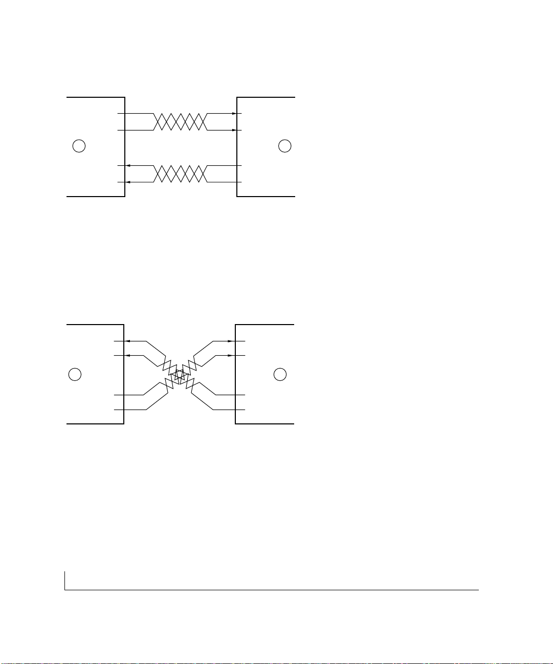
Twisted Pair Cables
For two devices to communicate, the transmitter of each device must be connected to
the receiver of the other device.The crossover function is usually implemented internally
as part of the circuitry in the device.Computers and workstation adapter cards are
usually media-dependent interface ports,called MDI or uplink ports.Most repeaters
and switch ports are configured as media-dependent interfaces with built-in crossover
ports, called MDI-X or normal por ts. Auto UplinkTMautomatically senses which
connection, MDI or MDI-X, is needed and makes the right connection.
Page 45
cabling guidelines C-4
Figure C-1 illustrates straight-through twisted pair cable.
Figure C-1.Straight-Through Twisted-Pair Cable
Figure C-2 illustrates crossover twisted pair cable.
Figure C-2.Crossover Twisted-Pair Cable
736EA
Tx
Rx
1
2
3
6
Tx
Rx
1
2
3
6
A B
Key:
A = Uplink or MDI port (as on a PC)
B = Normal or MDI-X port (as on a hub or switch)
1,2,3,6 = Pin numbers
737EA
B B
1
2
3
6
1
2
3
6
Tx
Rx
Tx
Rx
Key:
B = Normal or MDI-X port (as on a hub or switch)
1,2,3,6 = Pin numbers
Page 46
C-5cabling guidelines
Patch Panels and Cables
If you are using patch panels, make sure that they meet the 100BASE-TX requirements.
NETGEAR recommends Category 5 UTP cable for all patch cables and work area
cables to ensure that your UTP patch cable rating meets or exceeds the distribution
cable rating.
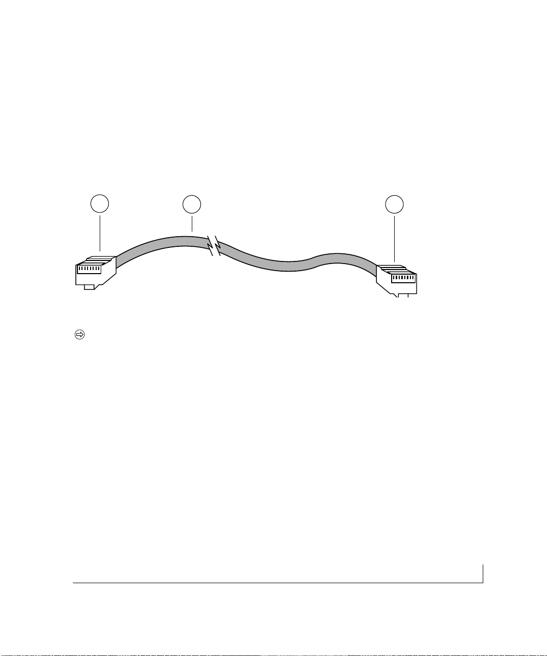
To wire patch panels,you need two Category 5 UTP cables with an RJ-45 plug at each
end, as shown in Figure C-3.
Figure C-3.Category 5 UTP Cable with Male RJ-45 Plug at Each End
Note: Flat “silver satin” telephone cable may have the same RJ-45 plug.
However, using telephone cable results in excessive collisions, causing the attached
port to be partitioned or disconnected from the network.
Using 1000BASE-T Gigabit Ethernet over Category 5 Cable
Overview
When using the new 1000BASE-T standard, the limitations of cable installations and
the steps necessary to ensure optimum performance must be considered.The most
important components in your cabling system are patch panel connections,twists of the
pairs at connector transition points,the jacket around the twisted-pair cable, bundling
of multiple pairs on horizontal runs and punch down blocks. All of these fac tors affec t
the performance of 1000BASE-T technology if not correctly implemented. The following sections are designed to act as a guide to correct cabling for 1000BASE-T.
87654321
87654321
2 1
1
Page 47

cabling guidelines C-6
Cabling
The 1000BASE-T product is designed to operate over Category 5 cabling.To further
enhance the operation, the cabling standards have been amended.The latest standard is
Category 5e,which defines a higher level of link performance than is available with
Category 5 cable.
If installing new cable, we recommend using Category 5e cable,since it costs about the
same as Category 5 cable.If using the existing cable, be sure to have the cable plant
tested by a professional who can verify that it meets or exceeds either ANSI/EIA/TIA568-A:1995 or ISO/IEC 11801:1995 Category 5 specifications.
Length
The maximum distance limitation between two pieces of equipment is 100 m,as per the
original Ethernet specification. The end-to-end link is called the "channel."
TSB-67 defines the "Basic Link" which is the portion of the link that is part of the
building infrastructure.This excludes patch and equipment cords.The maximum basic
link length is 295 feet (90 m).
Return Loss
Return loss measures the amount of reflected signal energy resulting from impedance
changes in the cabling link. The nature of 1000BASE-T renders this measurement very
important; if too much energy is reflected back on to the receiver, the device does not
perform optimally.
Unlike 10BASE-T and 100BASE-TX,which use only two of the four pairs of wires
within the Category 5,1000BASE-T uses all four pairs of the twisted pair. Make sure
all wires are tested — this is impor t ant.
Page 48

C-7cabling guidelines
Factors that affect the return loss are:
• The number of transition points,as there is a connection via an RJ-45 to another
connector, a patch panel,or device at each transition point.
• Removing the jacket that surrounds the four pairs of twisted cable.It is highly
recommended that, when RJ-45 connec tions are made, this is minimized to
1-1/4 inch (32 mm).
• Untwisting any pair of the twisted-pair cabling. It is important that any untwis ting be
minimized to 3/8 inch (10 mm) for RJ-45 connections.
• Cabling or bundling of multiple Category 5 cables. This is regulated by
ANSI/EIA/TIA-568A-3. If not correctly implemented,this can adversely affect all
cabling parameters.
Near End Cross Talk (NEXT)
This is a measure of the signal coupling from one wire to another, within a cable assembly,
or among cables within a bundle. NEXT measures the amount of crosstalk disturbance
energy that is detected at the near end of the link — the end where the transmitter is locat-
ed.NEXT measures the amount of energy that is "returned" to the sender end.The factors
that affect NEXT and crosstalk are exactly the same as outlined in the Return Loss section. The crosstalk performance is directly related to the quality of the cable installation.
Patch Cables
When installing your equipment, replace old patch panel cables that do not meet
Category 5e specifications. As pointed out in the NEXT section,this near end piece of
cable is critical for successful operation.
Conclusion
For optimum performance of your 1000BASE-T product, it is important to fully qualify
your cable installation and ensure it meets or exceeds ANSI/EIA/TIA-568-A:1995 or
ISO/IEC 11801:1995 Category 5 specifications. Ins tall Category 5e cable where
possible,including patch panel cables.Minimize transition points, jacket removal,and
untwist lengths. Bundling of cables must be properly installed to meet the requirements
in ANSI/EIA/TIA-568A-3.
Page 49

cabling guidelines C-8
Fiber Optic Cables
In North America, use EIA-569-A horizontal 62.5/125 µm multimode optical fiber
cable (ANSI/EIA/TIA-492AAAA).
Internationally,us e ISO/IEC 11801 62.5/125 µm multimode optical fiber cable (IEC
793-2 type A1b,with 1.0db/km attenuation and 500 MHz/km bandwidth).Refer to
Table C-2 for the minimum requirements of fiber optic cable.
Fiber Cable Specifications
Table C-2 lists the electrical requirements of fiber cable.
Table C-2. Electrical Requirements of Fiber Optic Cable
Specification Fiber Optic Cable
Number of strands Two
Cable type 62.5/125 µm multimode
fiber optic cable
Numerical aperture 0.275
Total link budget 11 db
Modal band 500 MHz/km
Zero dispersion wavelength 1295 to 1365 nm
Dispersion slope < 0.093 ps/nm 2 -km
Gigabit Cable Guidelines
Table C-3 lists the distance limitations for Gigabit fiber connections.
Table C-3. Gigabit Cable Guidelines
Multimode Fiber 62.5/125-Micron 50/125-Micron
Operating Range 2 to 260 meters 2 to 550 meters
Page 50

I-1index
A
Applications
Desktop Switching,3-1
Segment Switching and Bridging
from Mbps to 100 Mbps,3-2
Applying AC Power, 4-6
Auto Uplink,2-5
C
Cabling guidelines
Fast Ethernet Cable Guidelines,C-1
Category 5 Cable,C-2
Category 5 Cable Specifications, C-3
Twisted Pair Cables,C-3
Patch Panels and Cables,C-5
Using 1000BASE-T Gigabit Ethernet
over Category 5 Cable, C-5
Cabling,C-6
Length, C-6
Return Loss,C-6
Near End Cross Talk (NEXT), C-7
Patch Cables,C-7
Conclusion,C-7
Checking the Installation,4-6
Connecting Devices to the Switch,4-4
Connector pin assignments
RJ-45 Plug and RJ-45 Connector, B-1
Customer Support, iv
D
Data Rate,A-1
Desktop Switching,3-1
F
Fast Ethernet Cable Guidelines,C-1
Features,1-2
Front and Back Panels, 2-1
Fiber Optic Cables,C-8
Fiber Cable Specifications, C-8
G
Gigabit Cable Guidelines,C-8
I
Installation
Preparing the Site,4-2
Installing the Switch,4-3
Installing the Switch on a
Flat Surface,4-3
Installing the Switch in a Rack,4-3
Connecting Devices to the Switch,4-4
Checking the Installation,4-6
Applying AC Power, 4-6
Interface,A-1
L
LED Descriptions,2-4
N
Near End Cross Talk (NEXT), C-7
Network Protocol and
Standards Compatibility, A-1
Page 51

index I-2
P
Package Contents,1-5
Patch Panels and Cables,C-5
Physical Description
Front and Back Panels, 2-1
10/100 Mbps RJ-45 Ports,2-3
LED Descriptions,2-4
Module Bays, 2-5
Auto Uplink,2-5
Preparing the Site,4-2
R
Return Loss,C-6
RJ-45 Plug and RJ-45 Connector, B-1
S
Segment Switching and Bridging
from 10Mbps to 100 Mbps,3-2
T
Technical Specifications
Network Protocol and
Standards Compatibility, A-1
Data Rate,A-1
Interface,A-1
Electrical Specifications,A-3
Physical Specifications,A-2
Environmental Specifications, A-3
Electromagnetic Emissions,A-4
Electromagnetic Susceptibility, A-4
Safety Agency Approvals,A-4
Performance Specifications,A-2
Troubleshooting
Troubleshooting Chart, 5-1
Additional T r oubleshooting
Suggestions,5-3
Network Adapter Cards,5-3
Configuration, 5-3
Switch Integrity, 5-3
Auto Negotiation,5-3
Twisted Pair Cables,C-3
Page 52

NETGEAR, Inc.
4500 Great America Parkway
Santa Clara, CA 95054 USA
Phone: 1-888-NETGEAR
www.NETGEAR.com
M-FS700NA-0 July 2001
 Loading...