

Page 1
Page 2

Start Here
Congratulation s on your purchase of the NETGEA R™ Model FS102, Model FS104, or Model
FS108 Fast Ethernet Switch—a low-cost, high-performance network solution designed to support
power workgroups operating at 10 megabits per second (Mbps) or 100 Mbps.
In this installation guide that describes how to install and use the switches, all three switches are
referred to collectively as the Model FS102/FS104/FS108 switch. Each switch is listed
individually when information is provided that refers to a specific model.
Features
The Model FS102/FS104/FS108 switch has the following features:
• Two (Model FS102 switc h), four (Model FS104 swit ch), and eight (Model FS 108 switch)
vista automatic speed-sensing 10/100 Mbps Ethernet ports that provide fast information
exchange, resource sharing, and client or peer-to-peer communication using standard
Category 5 unshielded twisted pair (UTP) cable
• Automatic address learning function to build the packet forwarding information table (The
table contains up to 8,000 MAC addresses; that is, the switch can support networks with as
many as 8,000 devices.)
• Autosensing full-duplex or half-duplex mode of operation (Full-duplex mode doubles
throughput of point-to-point connections by letting individual ports transmit and receive
concurrently when the connecting device also supports full-duplex mode.)
• Wire-speed filtering and forwardi ng to supp ort the “tr affic cop” functio n by directin g traffic
to the appropriate port or network segment without slowing down the traffic
• Easy plug-and-play installation with no software to configure, which saves time and
minimizes the potential for configuration errors
• Normal/Uplink p ush button to simplify ne twork extensi on (The s witch can be connected to
another switch or hub using a standard , straight-through cable.)
• Two vista RJ-45 connec tor ports on the Model FS102 swit ch, four vista RJ-45 connector
ports on the Model FS104 switch, and eight vista RJ-45 connector ports on the Model FS108
switch (Each port has built-in LEDs to monitor individual port status.)
• LEDs that provide network traffic status and data transmission sp eed
• IEEE 8023u standard compliance, allowing incorporation with other 100BASE-TX Fast
Ethernet (100 Mb ps) products
• IEEE 802.3 10BASE-T standard compliance
• Compact, sturdy metal case design that enables easy desktop, wall-mount, or under-desk
installation
Model FS102, Model FS104, Model FS108 Fast Ethernt Switch Installation Guide
Page 3
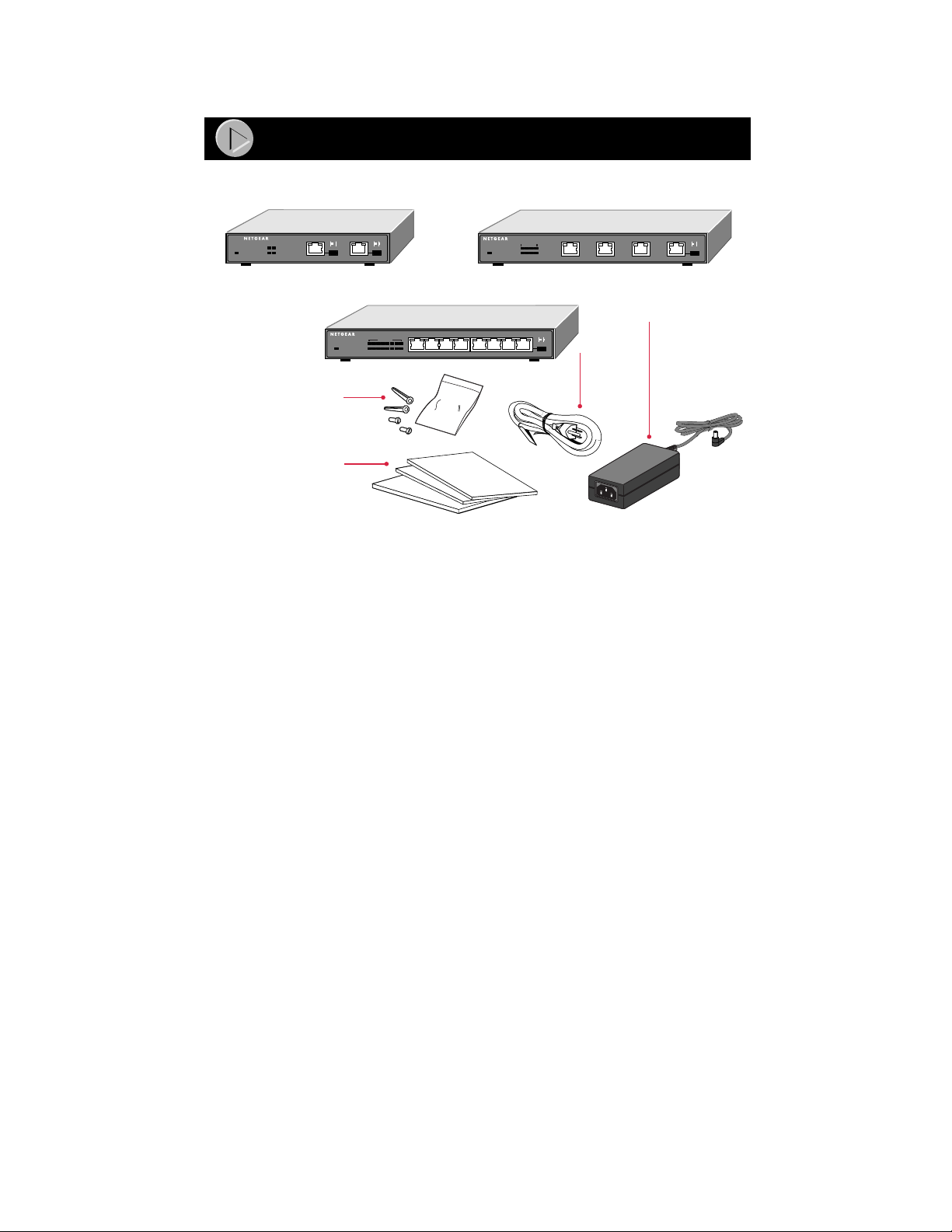
Package Contents
Model FS102 switch
FS102
FAST ETHERNET SWITCH
100 Mbps
12
Collision
LINK Rx
2
1
or
FAST ETHERNET SWITCH
Power
or
Model FS108 switch
FAST ETHERNET SWITCH
FS108
100 Mbps
12345678
Collision
Power
1
234 5678
LINK Rx
Wall mount
installation kit
Installation guide,
Warranty & Owner
Registration Card,
and Support
Information Card
Verify that your package contains the following:
• Model FS102, Mo del FS104, or Model FS108 switch
• Mounting kit (for wall installation)
• This installation guide
• Warranty & Owner Registration Card
• Support Information Card
• AC power cord and universal power cord adapter
Model FS104 switch
FS104
100 Mbps
1234
Collision
1
23
AC
power
cord
LINK Rx
4
Universal
power cord
adapter
8900FA
Model FS102, Model FS104, Model FS108 Fast Ethernt Switch Installation Guide
Page 4
Power
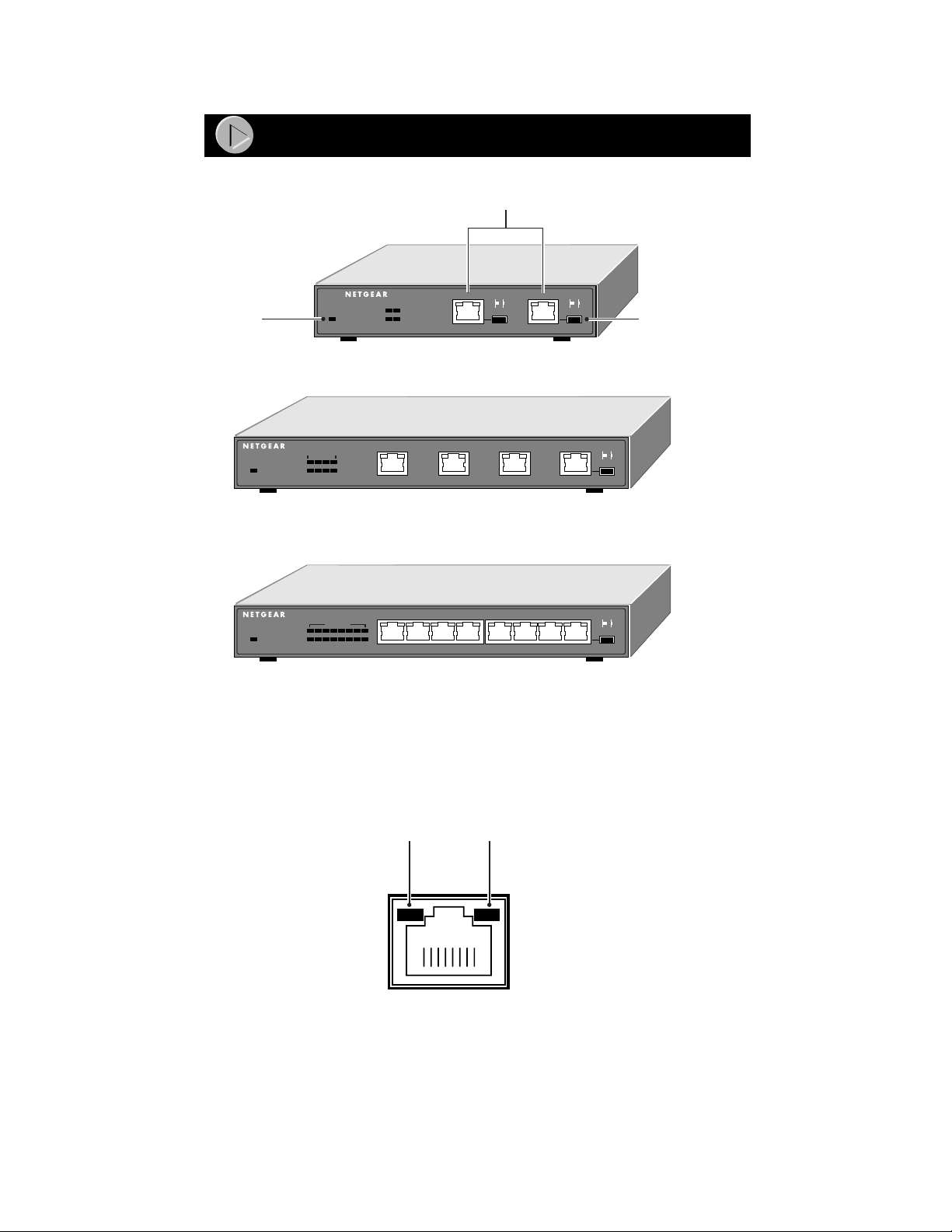
Product Illustration
Front Panel of the Model FS102 switch
FAST ETHERNET SWITCH
100 Mbps
12
Collision
Front Panel of the Model FS104 switch
1
Front Panel of the Model FS108 switch
Power
FAST ETHERNET SWITCH
100 Mbps
1234
Collision
Power
FS104
100 Mbps ports
FS102
1
23
LINK Rx
2
Normal/Uplink
push button
LINK Rx
4
FAST ETHERNET SWITCH
Power
FS108
100 Mbps
12345678
Collision
1
234 5678
LINK Rx
8899FA
Fast Ethernet Vista Ports with Built-in LEDs
All of the ports on the sw itch are 10/100 Mbps Ethernet po rts. The network ac cess speed for the
ports is automatically sensed and d isplayed on the front panel by the 100 Mbps LEDs.
Each port support s only unshielded twisted pair (UTP) cable using an 8-pin RJ-45 plug.
Each port uses vista RJ-45 connectors that have two LEDs—the Link LED and the FDX LED.
Link
LED
FDX
LED
8724EB
Model FS102, Model FS104, Model FS108 Fast Ethernt Switch Installation Guide
Page 5

LEDs
This table describes the activity of the Model FS102/FS104/FS108 switch LEDs.
Label Color Activity Description
Pwr (Power) Green On
Rx/Tx/Collision Green
100 Mbps Green On
Link
(located at the
top left corner
of each vista
10BASE-T port)
FDX
(located at the
top right corner
of each vista
10BASE-T port)
Off
Blinking
Yellow
Blinking
Off
Green On
Off
Green On
Off
Power is supplied to the switch.
Power is disconnected.
Packet transmission or reception is occurring on the port.
Data collisions are occurring on the port. The blinking action
corresponds to the number of collisions. When a collision
occurs, the connected device pauses and transmits again
after waiting a specified time. Note that occasional collisions
are normal.
The port is operating at 100 Mbps.
The port is operating at 10 Mbps.
A valid link is established on the port.
A link is not established on the port.
The port is operating in full-duplex mode.
The port is operating in half-duplex mode.
Model FS102, Model FS104, Model FS108 Fast Ethernt Switch Installation Guide
Page 6
Normal/Uplink Push Button
The Normal/Uplink push button on the front panel of the switch allows you to select u plin k (MDI)
or normal (MDI-X) wiring for either of the Ethernet ports on the Model FS102 switch, port 4 on
the Model FS104 switch, or port 8 on the Model FS108 switch. These ports are configured for
normal wiring to connect to a PC when the push button position is out. When the push button is
pressed in, these port s are configured for uplink wirin g to connect to anot her switch or to a hub ,
using a straight-through twisted pair cable.
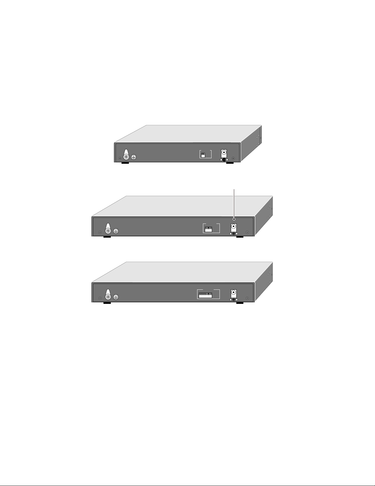
Rear Panel
The rear panel of the Model FS102/FS104/FS108 switch has full-duplex (FDX) and auto-duplex
(AUTO) toggle switches and a power adapter receptacle for the supplied power adapter.
12Vdc 1.2A
10/100 Mbps
1
FDX -
Force port to operate at Full Duplex and Half Duplex mode.
AUTO -
Enable port to determine duplex mode
automatically. Default is Half Duplex.
2
FDX
AUTO
– +
Rear Panel of the Model FS102 switch
Power receptacle
FDX -
Force port to operate at Full Duplex and Half Duplex mode.
AUTO -
Enable port to determine duplex mode
automatically. Default is Half Duplex.
10/100 Mbps
1
4
12Vdc 1.2A
FDX
AUTO
– +
Rear Panel of the Model FS104 switch
FDX -
Force port to operate at Full Duplex and Half Duplex mode.
AUTO -
Enable port to determine duplex mode
automatically. Default is Half Duplex.
10/100 Mbps
1234567
8
12Vdc 1.2A
FDX
AUTO
– +
Rear Panel of the Model FS108 switch
8901FA
FDX/AUT O Duplex Toggle Switches
Full-duplex mode is supported for all 10/100 Mbps ports and allows the port to transmit and
receive data at the same time. Full-duplex operation applies only to point-to-point access (for
example, when a switch is connected to a PC, a server, or another switch).
Setting the toggle switch to AUTO on the 10/100 Mbps port enables the port to determine duplex
mode automatically. In this mode of operation, the 10/100 Mbps port operates in either full- or
half-duplex, depending on the operating mode of the remote port. If the remote port cannot
provide the proper signal to indicate its capability, the 10/100 Mbps port on the switch defaults to
half-duplex mode. Repeaters and hubs use a common collision domain for all communications
and cannot commu nicate in ful l-du plex mode. The assoc iated 1 0 Mbp s port on the swi tch sho uld
be set to auto-duplex operatio n whe n conn e ct ing to thes e type s of devices.
One toggle switch is assigned to each 10/100 Mbps port and can be set to full-duplex (FDX) mode
or auto-duplex (AUTO) mode.
Model FS102, Model FS104, Model FS108 Fast Ethernt Switch Installation Guide
Page 7

Applications
The Model FS102/FS104/FS108 switch is designed to provide flexibility in configuring your
network connections. Each switch can be used as a standalone device or can be used with 10 Mbps
or 100 Mbps hubs or othe r interconne ction devices in variou s configurations. The configurati on
examples in this section illustrate the integration of the switches in various network environments
using other NETGEAR products. These examples include a network of a few workstations
connected to a printer or a segmented network with multiple users or workgroups and other
networking devices.
Although the examples illustrate specific switches, any of the switches can be used in the network
configurations shown.
Desktop Switching
The Model FS108 switch is us ed as a d eskto p switch to build a small n et wo rk tha t ena bles u ser s to
have 100 Mbps access to a file server.
Key
100 Mbps
10 Mbps
Model FS108 switch
FAST ETHERNET SWITCH
FS108
100 Mbps
12345678
Power
Collision
1
234 5678
LINK Rx
8902FA
If a full-duplex adapter card is installed in the server or PC, a 200 Mbps connection is possible on
the port wher e t he server or PC is co nnected.
Model FS102, Model FS104, Model FS108 Fast Ethernt Switch Installation Guide
Page 8

Segment Switching
The Model FS108 switch is used as a switch that segments a network into multiple connected
pieces, increasing overall bandwidth and throughput. The Model FS108 switch can segment
networks that are built with the NETGEAR Model DS108 Dual Speed Hubs.
Model FS108 switch
FAST ETHERNET SWITCH
FS108
100 Mbps
12345678
Collision
Power
1
234 5678
LINK Rx
Model DS108 hubModel DS108 hub
Auto 10/100 MbpsDUAL SPEED Auto 10/100 MbpsDUAL SPEED
8903FA
Extending a Network Diameter
Ethernet specifications limit the length of cable between hubs and PCs to 100 meters (m) for a
total of 200 meter s. By addi ng F as t Ethe rnet s wit che s betw een h ubs, a netw or k is e x pande d b y 20 0
meters with the addition of each switch. The illustration below shows two NETGEAR Model
FE108 Fast Ethernet Hubs integrated with a Model FS108 switch to extend a network.
Model FS108 switch
FAST ETHERNET SWITCH
FS108
100 Mbps
12345678
Collision
Power
1
234 5678
LINK Rx
100 m
Model FE108
hubs
8904FA
Model FS102, Model FS104, Model FS108 Fast Ethernt Switch Installation Guide
Page 9

Bridging from 10BASE-T to 100BASE-TX Networks
The Model FS108 switch can function as a two-port bridge connecting traditional 10BASE-T
Ethernet networks to 100BASE-TX Fast Ethernet networks. User s requiring increased network
bandwidth can be up grad ed t o 100 Mb ps wh ile remain in g c onn ected to t he re st of the n etwork by
integrating the Model FS108 Fast Ethernet Switch with the NETGEAR Model EN108 Ethernet
Hub and the NETGEAR Model FE108 Fast Ethernet Hub.
Key
200 Mbps
Model FS108 switch
100 Mbps
10 Mbps
Model FE108 hub
FS108
100 Mbps
12345678
Collision
Power
Model EN108
1
234 5678
LINK Rx
FAST ETHERNET SWITCH
hub
10 BASE-T HUB
EN108
Pwr
Col
1234 5678
LINK Rx
8967FA
High-Bandwidth File Servers
The Model FS104 switch increases bandwidth for workgroups and strengthens network
throughput when accessing high-volume file servers. The switch provides parallel commun i cation
between each of the ports. This method of communication allows multiple conversations to occur
concurrently, expands overall throughput , and allows key servers or oth er heavily used devices to
be available to more users. The Model FS104 Fast Ethernet Switch can be integrated with a
NETGEAR Model FE108 Fast Et hernet Hub and a NETGEAR Model DS108 Dual Speed Hub. A
full-duplex configurable adapte r card installed in the s erver provides up to 200 Mbps maxi mum
data throughput.
Model FS104
switch
Model FE108 hub Model DS108 hub
Auto 10/100 MbpsAuto 10/100 MbpsDUAL SPEED
8906FA
Model FS102, Model FS104, Model FS108 Fast Ethernt Switch Installation Guide
Page 10

Prepare the Site
Before you begin installing your switch, prepare the installation site. Make sure your operating
environment meets the operating environment requirement s of the equipment.
Characteristic Requirement
Temperature Ambient temperature between 0q and 40q C (32q and 104q F).
Operating humidity Maximum relative humidity of 90%, noncondensing.
Ventilation Minimum 2 inches (5.08 cm) on all sides for cooling.
Operating conditions At least 6 feet (1.83 m) to nearest source of electromagnetic noise (such
Power Adequate power source within 6 feet (1.83 m).
No nearby heat sources such as direct sunlight, warm air exhausts, or
heaters.
Adequate airflow in room or wiring closet.
as photocopy machine or arc welder).
Install the Switch
To install your switch on a flat surface, you do not need any special tools. Be sure the switch is
positioned with at least 2 inches of space on all sides for ventilation.
To install the switch on a wall, measure the dista nce between the moun ting holes on the ba ck of
the switch and mark the wall to match the location of the mounting holes on the switch. At the
marks, screw into the wall the two screws in the mounting kit included in your package contents.
Choose a location that i s near the devices to be connected, is close to an elec trical outlet, and
provides at least 2 inches of space all arou nd the switch for ventilation.
Connect Devices to the Switch
Before connecting the switch, be sure you review “Applications” for to determine the appropriate
configuration for your networking needs.
To connect the switch:
1. Connect the devices to the 10/100 Mbps ports on the switch, using Category 5 UTP
cable and an RJ-45 plug.
Note: Ethernet specifications limit the cable length between your PC or server and the
switch to 328 feet (100 meters).
2. Set the Normal/Uplink push button.
The Normal/Uplink push button eliminates the need to use a crossover twisted pair cable for
daisy-chaining or cascadin g. Use the fol lowing guidelin es to configure port 1 and port 2 on
the Model FS102 switch, port 4 on the Model FS104 switch, or port 8 on the Model FS108
switch for uplink or norma l w ir ing :
• Configure the port for normal wiring if the port is to be connected to an uplink-wired
device, such as a network station or a PC.
• Configure the port for uplink wiring if the port is to be connected to a normal-wired
device, such as a 100 Mbps hub or another switch.
The remaining (normal) ports on the switch cannot be configured for uplink wiring. If you are
using one of these ports t o connect t o another n ormal port, yo u must u se a crossover twisted
pair cable to connect the two ports. Refer to “Cable and Connector Information” for
information about crossover twisted pair cable and straight-through twisted pair cable.
Model FS102, Model FS104, Model FS108 Fast Ethernt Switch Installation Guide
Page 11

Verify Installation
3. Set the FDX or AUTO toggle switches on the re a r pa nel for the selected duplex mode.
A hub and repeater use a common collision domain for all communications and cannot
support full-dup lex mode . W h en conn ect ing any of t he 10 /1 00 Mb ps por ts o n the swi tch t o a
hub, set the port to AUTO. The switch must also be set to AUTO when connecting to any
device that does not use NWay autonegotiation to detect the operating mode. Setting the
toggle switch to AUTO will cause th e port to default to half-du ple x m od e whe n co nn ecti ng to
a port that does not use autoneg oti ation.
When connecting to a PC, a server, or another switch, the duplex setting for the port must be
the same as the duplex setting on the PC, server, or other switch.
To set the 10/100 Mbps ports for the selected duplex mode:
• Move the toggle switch into the down position (to AUTO) for auto-duplex mode.
The 10/100 Mbps ports will negotiate and automatically determine the duplex mode
based on the mode of the connected port. If the connected port cannot autonegotiate,
the 10/100 Mbps port will default to half-duplex mo de. The factory setting of the duplex
toggle switches is AUTO.
• Move the toggle switch i nto the up pos ition (to F DX) for full-du plex mode.Th e duplex
switch must be set to FDX if you a re connecting to legacy full-duplex 100 Mbps devices
that do not gen e rate signals indicating duplex mode. If the duplex switch i s set to AUTO
mode, the 10/100 Mbps ports will default to half-duplex mode because the port does not
receive the proper signal.
4. Connect one end of the DC power adapter cable to the power outlet on the rear panel of
the switch and the other end of the power adapter cable to the wall outlet.
When power has been applied to the switch:
• The green Pwr (Power) LED on the front panel is on.
• The green Link LED on each connected port is on.
When the switch is connected and operating, refer to the table in “LEDs” for information about
the LEDs and their activity.
Model FS102, Model FS104, Model FS108 Fast Ethernt Switch Installation Guide
Page 12

Troubleshooting Information
Symptom Cause Solution
Green Link LED is
off on an active
port.
Green Link LED is
intermittent on an
active port.
Green Link LED is
off on ports 1 or 2
on the Model
FS102 switch, port
4 on the Model
FS104 switch, or
port 8 on the
Model FS108
switch.
Green 100 Mbps
LED is off when
operating in a Fast
Ethernet network.
Green Link LED is
on and Green FDX
LED is off when
connected to a full
duplex network.
Port connection is
not functioning.
Port connection is
not functioning.
Port connection is
not functioning.
Port is operating in
10 Mbps mode.
Port is operating in
half-duplex mode.
Make sure the attached device is powered and there is
a proper UTP connection at that end.
Make sure the network adapter card installed in the
PC is in working condition. Verify that the network
adapter card is100 Mbps capable and that the 100
Mbps LED and Link LEDs are on at the network
adapter card in the PC.
Make sure the proper cable is installed, and check for
miswired cable pairs or loose connectors.
Make sure the port termination at both the switch and
the device end is correct. Check the crimp on the RJ45 connectors. In a Fast Ethernet operation, the
quality of the crimp on the connector is important. It is
also important that only Category 5 cable is used and
that it is certified for 100 Mbps operation.
Make sure the length of the UTP cable from the switch
to the device does not exceed 328 feet (100 meters).
Using cable test equipment, make sure the cable
meets the crosstalk, attenuation, and impedance
specifications as required by the 100BASE-TX
standard. Refer to “Cable and Connector Information”
for information about cable specifications.
Check the Normal/Uplink push button on the front
panel.
If you are using a straight-through cable connected to
a PC or other MDI-wired device, make sure the
Normal/Uplink push button is set in the Normal
position.
If you are using a straight-through cable connected to
a router or another switch, make sure the Normal/
Uplink push button is set in the Uplink position.
Try the alternate position of the Normal/Uplink push
button to turn the Link LED on.
Refer to “Cable and Connector Information” for cable
information.
Make sure the adapter card is capable of 100 Mbps
operation and set for 100 Mbps operation if it is not
autosensing.
Make sure the duplex switch on the Model FS102/
FS104/FS108 switch is set for full-duplex operation.
Make sure the connected device is capable of fullduplex transmission.
Model FS102, Model FS104, Model FS108 Fast Ethernt Switch Installation Guide
Page 13

Symptom Cause Solution
Yellow Rx/Tx
Collision LED is
blinking
excessively.
Green FDX LED is
off when you have
set the port to
operate in fullduplex mode.
Data collision is
occurring on the port.
Port is operating in
half-duplex mode.
The port and switch might be functioning correctly .
However, check the following to make sure that
excessive collisions are normal (as in most Ethernet
networks) and not caused by:
• Incorrect cabling or connectors
• Wiring techniques
• Mismatched duplex operating mode settings
Make sure the connected device is able to operate at
half-duplex mode and check the specifications of the
connected device to make sure it has the ability to
signal the operating mode. Verify that the connected
device is operational. If the connected device is an
adapter card, make sure you have an adapter card
that is capable of 100 Mbps operation and set to 100
Mbps if it is not autosensing.
Cable and Connector Information
Twisted Pair Cables
For two devices to communicate, the transmitter o f each device must be c onn ected t o the receiver
of the other device. The crossover function is usually implemented internally as part of the
circuitry in the device. Most ports on switches and repeaters have media-dependent interfaces with
crossover ports. These ports are referred to as MDI-X or normal ports. Computer and workstation
adapter cards are u s ually media-depe ndent interface ports referred to as MDI or upli nk ports.
The figures illustrate the use of straight-through and crossover twisted pair cables.
Uplink or
MDI port
Tx
Rx
Normal or
MDI-X port
1
Rx
2
3
Tx
6
Straight-through
twisted pair cable
1
2
3
6
Crossover
twisted pair cable
Normal or
MDI-X port
1
Rx
2
3
Tx
6
Normal or
MDI-X port
1
Rx
2
3
Tx
6
8146EB
Model FS102, Model FS104, Model FS108 Fast Ethernt Switch Installation Guide
Page 14

RJ-45 Connector
The RJ-45 connector (shown in the illustration with an RJ-45 plug) is used to connect
workstations and switch es through unshielded twisted pair cable. The RJ-45 connector ac cepts
four-pair Category 3 or Category 5 UTP cable. Only two pairs are used for 10BASE-T wiring.
12345678
18
711EA
RJ-45 Connector
Pin Assignment
1 Input Receive Data + Output Transmit Data +
2 Input Receive Data - Output Transmit Data 3 Output Transmit Data + Input Receive Data +
6 Output Transmit Data - Input Receive Data 4, 5, 7, 8 Not used Not used
Normal Assignment:
Uplink Assignment:
Port 1 or 2 on the Model FS102 Switch
Port 4 on the Model FS104 Switch
Port 8 on the Model FS108 Switch
Model FS102, Model FS104, Model FS108 Fast Ethernt Switch Installation Guide
Page 15

Technical Specifications
General Specifications Model FS102 Switch Model FS104 Switch Model FS108 Switch
Network Protocol and
Standards Compatibility
Data Rate
Interface
Power Consumption
Input Voltage
(Power Adapter)
Physical Specifications
Dimensions: 6.2 x 1.06 x 4.1 in.
Weight: 1.09 lb; 0.50 kg 1.60 lb; 0.73 kg 1.60 lb; 0.73 kg
Environmental Specifications
Operating temperature: 0qto 40qC (32qto 104qF)
Operating humidity: 90% maximum relative humidity, noncondensing
Electromagnetic
Emissions
Electromagnetic Suscep tib ility
Electrostatic discharge
(ESD):
Radiated electromagnetic
field:
Electrical fast transient/burst: IEC 801-4, Level 2 IEC 801-4, Level 2 IEC 801-4, Level 2
Electrical surge: IEC 801-5, Level 2 IEC 801-5, Level 2 IEC 801-5, Level 2
Safety Agency Approvals
for Power Adapter
Performance Specifications
Frame filter rate: 14,800 frames/second, maximum on 10 Mbps port
Frame forward rate: 14,800 frames/second, maximum on 10 Mbps port
Network latency (using 64byte packets):
Address database size: 8,000 media access control (MAC) addresses per port
Addressing: 48-bit MAC address
Queue buffer: 10/100 Mbps ports: 1 MB of buffer space
100 Mbps with 4B/5B encoding and MLT-3 physical interface for 100BASE-TX
15.8 x 2.7 x 10.3 cm
CE mark, commercial; FCC Part 15, Class A; EN 55 022 (CISPR 22), Class A;
CE mark, commercial CE mark, commercial CE mark, commercial
IEC 801-2, Level 2/3/4 IEC 801-2, Level 2/3/4 IEC 801-2, Level 2/3/4
IEC 801-3, Level 2 IEC 801-3, Level 2 IEC 801-3, Level 2
CE mark, comm ercial
UL listed (UL 1950)
CSA certified
(CSA 22.2 #950)
TUV licensed
(EN 60 950)
T-Mark
ISO/IEC 802-3 (ANSI/IEEE 802.3i) 10BASE- T Ethernet
IEEE 802.3u, IEEE802.3x 100BASE-TX, Fast Ethernet
10 Mbps differential Manchester encoded
RJ-45 connector for 10BASE- T or 100BASE-TX Ethernet interface
8 W 15.2 W 12 W
12 V dc 12 V dc 5 V dc
9.27 x 1.06 x 4.1 in.
23.5 x 2.7 x 10.3 cm
VCCI Class 1 ITE
CE mark, commercial
UL listed (UL 1950)
CSA certified
(CSA 22.2 #950)
TUV licensed
(EN 60 950)
T-Ma rk
148,000 frames/second, maximum on 100 Mbps port
148,000 frames/second, maximum on 100 Mbps port
10 Mbps to 10 Mbps: 73 microseconds maximum
10 Mbps to 100 Mbps: 26 microseconds maximum
100 Mbps to 10 Mbps: 62 microseconds maximum
100 Mbps to 100 Mbps: 15 microseconds maximum
for each port
9.27 x 1.06 x 4.1 in.
23.5 x 2.7 x 10.3 cm
CE mark, commercial
UL listed (UL 1950)
CSA certified
(CSA 22.2 #950)
TUV licensed
(EN 60 950)
T-Mark
10/100 Mbps ports: 128 k
of buffer space for each
port
Model FS102, Model FS104, Model FS108 Fast Ethernt Switch Installation Guide
Page 16

© 1998 by NETGEAR, Inc. All rights reserved.
Trademarks
Bay Networks is a registered trademark of Bay Networks, Inc.
NETGEAR is a trademark of Bay Networks, Inc.
All other trademarks and registered trademarks are the property of their respective owners.
Statement of Conditions
In the interest of improving internal design, operational function, and/or reliability, NETGEAR reserves the right to make changes to the products
described in this document without notice.
NETGEAR does not assume any liability that may occur due to the use or application of the product(s) or circuit layout(s) described herein.
Certificate of the Manufacturer/Import er
It is hereby certified that the NETGEAR Model FS102/104/108 Fast Ethernet Switch has been suppressed in accordance with the conditions set out
in the BMPT-AmtsblVfg 243/1991 and Vfg 46/1992. The operation of some equipment (for example, test transmitters) in accordance with the
regulations may, howev e r, be subject to certain restrictions. Please refer to the notes in the operating instructions.
Federal Office for Telecommunications Approvals has been notified of the placing of this equipment on the market and has been granted the right
to test the series for compliance with the regulations.
Voluntary Control Council for Interference (VCCI) Statement
This equipment is in the first category (information equipment to be used in commercial and/or industrial areas) and conforms to the standards set
by the V oluntary Control Council for Interference by Data Processing Equipment and Electronic Office Machines that are aimed at preventing radio
interference in commercial and/or industrial areas.
Consequently, when this equipment is used in a residential area or in an adjacent area thereto, radi o int erference may be caused to equipment such
as radios and TV receivers.
Federal Communications Commission (FCC) Compliance Notice: Radio Frequency Notice
Note: This equipment has been tested and found to comply with the limits for a Class A digital device, pursuant to Part 15 of the FCC rules. These
limits are designed to provide reasonable protection against harmful interference when the equipment is operated in a commercial environment.
This equipment generates, uses, and can radia te r adio frequency energy. If it is not installed and used i n accordance with the instruction manual, it
may cause harmful interference to radio communications. Operation of this equipment in a residential area is likely to cause harmful interference,
in which case users will be required to take whatever measures may be necessary to correct the interference at their own expense.
EN 55 022 Statement
This is to certify that the NETGEAR Model FS102/104/108 Fast Ethernet Switch is shielded against the generation of radio interference in
accordance with the application of Council Directive 89/336/EEC, Article 4a. Conformity is declared by the application of EN 55 022 Class A
(CISPR 22).
This is a Class A product. In a domestic environment, this product may cause radio
interference, in which case the user may be required to take appropriate measures.
Canadian Department of Communications Radio Interference Regulations
This digital apparatus (NETGEAR Model FS102/104/108 Fast Ethernet Switch) does not exceed the Class A limits for radio-noise emissions from
digital apparatus as set out in the Radio Interference Regulations of the Canadian Department of Communications.
Règlement sur le brouillage radioél ect r ique du ministère des Communications
Cet appareil numérique (NETGEAR Model FS102/104/108 Fast Ethernet Switch) respecte les limites de bruits radioélectriques visant les appareils
numériques de classe A prescrites dans le Règlement sur le brouillage radioélectrique du ministère des Communications du Canada.
Model FS102, Model FS104, Model FS108 Fast Ethernt Switch Installation Guide
Page 17

NETGEAR, Inc.
A Bay Networks Company
4401 Great America Parkway
Santa Clara, CA 95054 USA
Phone: 888-NETGEAR
*M-FS100NA-1*
 Loading...