

Page 1
Installation Guide
Cable/DSL ProSafe Wireless-Ready Firewall
MODEL FR114W
Page 2
Introduction
Thank you for purchasing a NETGEAR FR114W Cable/DSL ProSafe Wireless-Ready Firewall
with Print Server. A firewall is a special type of router that incorporates features for network
security. With this firewall you can have secure Internet access through a high-speed DSL or cable
modem and share the single modem with several computers. Provides the ability to install a
wireless notebook card for wireless networking functionality.
This installation guide shows you how to connect the firewall and configure it and your
computers for secure Internet access. Setup is easy—follow the instructions in this guide and
your system will be up and running quickly.
If you have problems, there is a troubleshooting section on page 13 to help you—or you can
get more detailed troubleshooting information from the Reference Manual on the CD, online
from www.NETGEAR.com or by phone.
Installation Overview
Estimated time: 15 to 30 minutes
1. Gather the configuration information you have for your working DSL or cable modem
connection to the Internet.
2. Install the firewall between the DSL or cable modem and one computer.
3. Configure that computer to work with the firewall and restart the computer and modem.
4. Configure the firewall and go online to test the connection.
5. Connect other computers, configure them and restart each. (optional)
On the FR114W Resource CD, you’ll find the Installation Assistant, which supplements the
instructions in this installation guide by animating the step-by-step procedures given here. For
more detailed information about installation, troubleshooting and configuration
procedures, see the Reference Manual on the CD.
1
Model FR114W ProSafe Wireless-Ready Firewall
Page 3
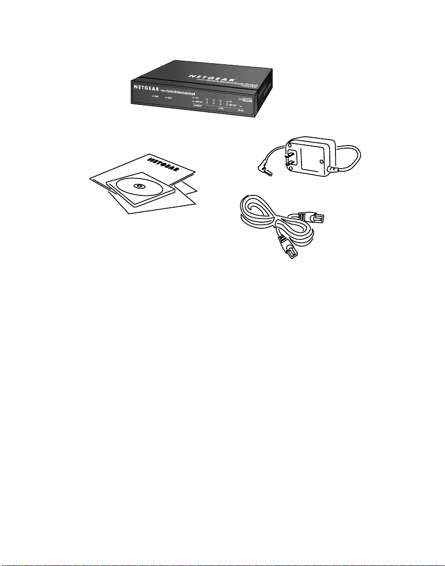
What’s in the Box
When you open the box, verify that you received everything.
The package includes:
• FR114W Cable/DSL ProSafe Wireless-Ready Firewall
• AC power adapter
• Ethernet patch cable
• FR114W Resource CD, including a full Reference Manual and Installation Assistant.
• FR114W Installation Guide (this document)
• Warranty and registration card
• Support information card
If you don’t have everything listed above, see the support information card for contact
information. If the support information card is missing, you can get contact information at
www.NETGEAR.com in the Customer Service area.
2
Model FR114W ProSafe Wireless-Ready Firewall
Power adapter
FR114W Resource CD,
installation guide, support
information card &
warranty/registration card
Category 5
100 Mbps
Ethernet cable
Page 4
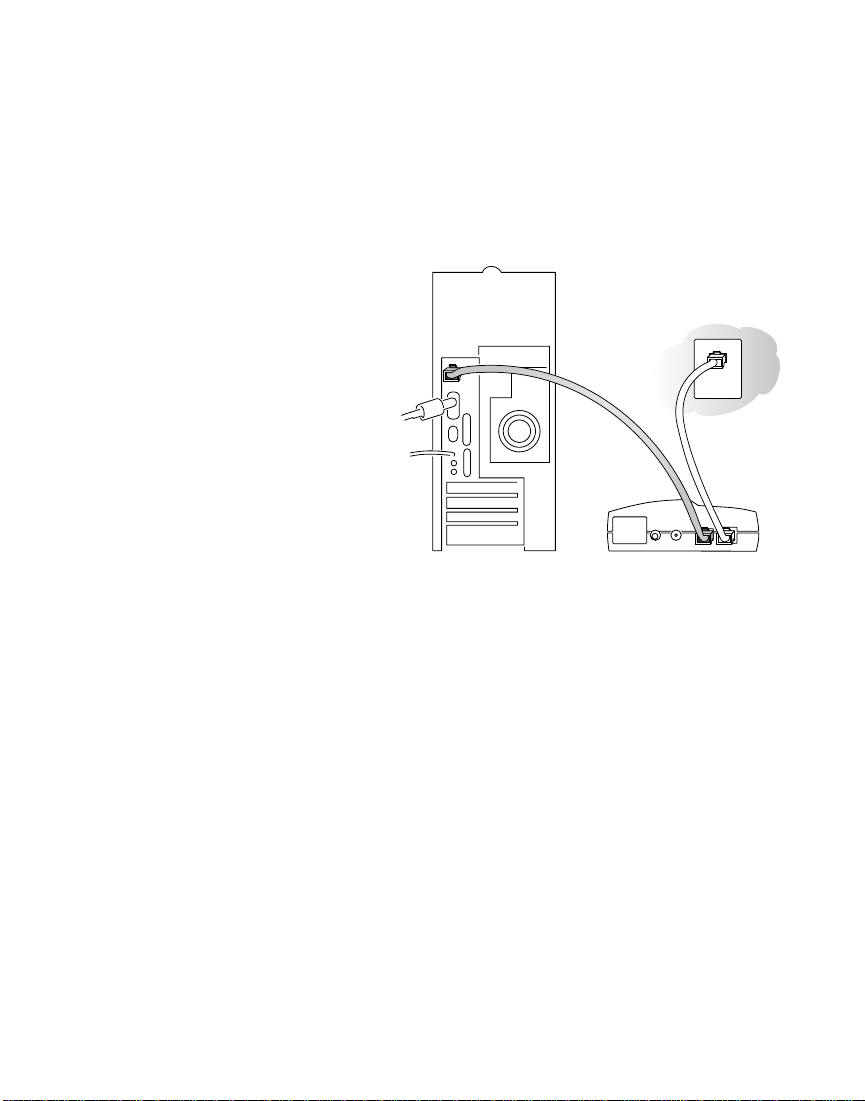
Gather Configuration Information for
Your Working Connection to the Internet
Before installing the FR114W firewall, you
should have an external DSL or cable
modem with an Ethernet port set up and
working with one computer. You’ll be
installing the firewall between the modem
and the computer.
For each computer that you want to
connect to the firewall, you must have
• An available RJ-45 Ethernet port (or
adapter) — either built-in or from a
network interface card (NIC) installed
in the computer
OR
an 802.11b-compliant wireless adapter.
• TCP/IP installed.
• If your computer is a Windows
®
computer, it must have the Client for Microsoft®Networks software installed.
Note: Please see the Reference Manual on the CD if you need help installing
TCP/IP software or the Client for Microsoft Networks software on any Windows
computer that hasn’t been networked previously.
• A Category 5 (Cat 5) Ethernet patch cable
Note: There is one cable in the box with the firewall.
3
1
1
Note: If you have a cable
modem, you will have a cable
connection between the
modem and your cable outlet.
DSL modem
Page 5

Connection information
Later in the setup process you’ll need to configure the firewall to work with your network. A
Setup Wizard is available to help you through this procedure. You can configure the firewall
yourself using information that you can get from your computer or your ISP about your
current Internet connection.
The next page includes blanks for you to fill in and refer to later. To get the needed
information from your computer:
• (Windows 98/Me) Open the Network control panel, select the TCP/IP entry, and
click Properties.
• (Windows 2000/XP) Open Local Area Network Connection and click Properties.
• (Macintosh
®
) Open the TCP/IP (or Network) control panel.
Your ISP should have provided you with a summary sheet of all the information needed to connect
your computer to the Internet. If you cannot locate the information, you’ll have to contact your ISP.
An ISP Guide is included with your firewall’s documentation, either as a printed card or on the
Resource CD. The ISP Guide contains specific configuration guidelines for connecting to
many popular ISPs.
4
Page 6

Host and Domain Names
Some ISPs use a specific host or domain name—like jsmith or earthlink.net. If you haven’t
been given specific information about host or domain names then use the following examples
as a guide:
• If your main e-mail account with your ISP is aaa@yyy.com, then use aaa as your host
name. (Your ISP might call this your account name, user name, or system name.)
• If your ISP’s mail server is mail.xxx.yyy.com, then use xxx.yyy.com as the domain name.
Host name:_____________________________________
Domain name: __________________________________
Login Name
If your ISP requires a login name and password (possibly because you have a PPPoE account),
fill in the following:
Login name:____________________________________
(may be your full e-mail address)
Password:______________________________________
Note: The login name could be called a user name or account name by your ISP.
The login name is case sensitive. You must type it exactly as given by your ISP. For
example, c_jones is a different login name than C_Jones or cjones.
Fixed (or static) IP address
If you have a static IP address through your ISP, fill in the following information:
IP address: _____._____._____._____
Subnet mask: _____._____._____._____
Gateway IP address:_____._____._____._____
DNS server address information
If you were given specific Domain Name System (DNS) server addresses, fill in the following:
DNS Server IP address(es): _____._____._____._____
_____._____._____._____
5
Page 7

Install the Firewall
After unpacking the box and locating the
configuration information, you’re ready to install
the firewall. If you will be upgrading your
FR114W for wireless operation, perform the steps
in the following section. Otherwise skip to
“Connecting the Firewall to your network” below.
Installing a Wireless Card in
the FR114W
To upgrade the FR114W for wireless operation,
you must purchase and install a NETGEAR
802.11b Wireless PC Card. The firewall will
function normally without a wireless adapter card,
but will not have wireless connectivity. To install
the 802.11b Wireless PC Card in your FR114W,
follow these steps:
1. Locate the wireless adapter card slot on the rear panel of the FR114W.
2. Remove the rubber dust cover from the slot.
3. With the FR114W’s power off, slide the Wireless PC card into the slot with the card’s
front label and LED facing up.
4. Be sure that the Wireless PC card is securely seated into the internal connector.
The blue plastic end cap of the Wireless PC card should be outside of the FR114W’s case.
Note: You must use a NETGEAR wireless PC card as not all manufacturer’s PC
cards are compatible.
Connecting the Firewall to your Network
Note: You do not have to power down any equipment to do this, but if you need to
move your computers (perhaps to get to ports in the back), you may want to shut
down the computers before moving them around.
1. Locate the Ethernet cable currently going from the DSL or cable modem to the computer
that you use to access the Internet.
Note: You must use this cable to connect the DSL or cable modem to your firewall
since this may be a special cable even though it looks like other LAN cables.
6
WIRELESS PCMCIA
WIRELESS PCMCIA
NETGEAR WIRELESS ADAPTER ONLY
Model FR114W ProSafe Wireless-Ready Firewall
Normal
4321
UpLink
10/100M
modem
LOCAL
INTERNET
12VDC O.5A
DSL
Page 8

2. Remove this cable from the computer and insert that end into the Internet port on the
rear panel of the firewall.
3. Use the Ethernet patch cable that came with the firewall to connect the computer to one
of the four numbered local Ethernet ports on the rear panel of the firewall.
4. Connect the power adapter’s cord into the back of the firewall and then plug the adapter
into a power source (such as a wall socket or power strip).
Note: If you want to connect other computers to the firewall, don’t connect them
now. Do that after you know that the modem/firewall setup works with one
computer.
Check the setup
• The Test light turns on for a few seconds and then goes off.
Note: If the Test light remains on for more than one minute, go to Troubleshooting
on page 13.
• The Power and Internet Link lights should be lit.
• The WLAN light should be lit.
• If your computer is on, the Local Link light should be on for the port number that your
computer is connected to.
Note: If the port connection is a 100 Mbps connection, the 100 light should be on.
If either the Power, Internet Link, or Local port Link light isn’t lit, go to Troubleshooting on
page 13.
7
Page 9

Configure the Computer to Work with the
Firewall and Restart the Network
Next, make sure that the computer can interact with the firewall. To do this, configure the
TCP/IP settings on the computer and then restart the network. How you do this depends on
your computer.
Windows Operating System
Normally, you can leave the TCP/IP setup parameters at their factory default settings unless
you have a specific reason to change them. You should verify that the computer is set to ‘obtain
an IP address automatically’ in the Network control panel.
Windows 98 or Me
1. Choose Settings>Control Panel from the Start menu.
2. Double-click the Network icon.
3. Click the Configuration tab.
4. In the list of installed network components, select the TCP/IP entry for the computer’s
Ethernet or wireless adapter.
5. Click Properties.
6. Click the IP Address tab.
7. Check that Obtain an IP Address Automatically ia selected, select if not.
8. Click the Gateway tab.
9. Select and remove any IP Gateway addresses that are listed.
10. Click OK and click OK again to close the Network control panel.
11. Go to Restarting the Network on the next page.
Windows 2000 or XP
1. Right-click My Network Place and choose Properties.
2. Double-click Local Area Network Connection and
click Properties.
3. Select Internet Protocol (TCP/IP) and click Properties.
4. Select Obtain IP address automatically.
5. Click OK twice and click Close.
6. Go to Restarting the Network.
8
3
3
Windows 98/Me
Page 10

Macintosh Operating System
Mac OS®8.6 or 9.x
1. Choose Control Panels >TCP/IP from the Apple
menu.
2. If not already selected, select Ethernet in the
Connect via list.
3. Select Using DHCP Server in the Configure list.
4. Click the close box.
5. If asked if you want to save this configuration,
click Save.
6. Go to Restarting the Network.
Mac OS X
1. Choose System Preferences from the Apple menu.
2. Double-click Network.
3. If not already selected, select Built-in Ethernet in the Configure list.
4. If not already selected, select Using DHCP in the TCP/IP tab.
5. Click Save.
6. Go to Restarting the Network.
Linux®or UNIX®Operating System
If you’re installing the firewall with a Linux-based or UNIX-based computer see your system
documentation for TCP/IP and networking setup information.
Restarting the Network
Once you’ve set up your computer to work with the firewall, you must reset the network for
the devices to be able to communicate correctly.
1. Turn off the DSL or cable modem, wait 15 seconds, and then turn it on again.
Note: If the modem doesn’t have an on/off switch, either pull the modem’s power
adapter out of the wall socket or power down the power strip.
2. If the firewall was powered down, power it up again and wait until the Test light turns off.
3. Restart the computer that is connected to the firewall.
Note: You may also configure the firewall from a wireless PC. In that case, set the
PC’s SSID to the firewall’s default SSID: Wireless and be sure to Disable WEP encryption.
9
Page 11

Configure the Firewall and Test the
Connection
Now you configure the firewall to work with your DSL or cable connection. You configure your
firewall using Internet browser software such as Microsoft®Internet Explorer 5.0 or Netscape
Navigator®4.7 or later. You can either use the Setup Wizard or configure the firewall manually.
1. Start a browser on the computer connected to the firewall.
2. In the Address or Location box, type http://192.168.0.1 and press Enter or Return.
Note: You may want to bookmark this address in your browser for handy access in
the future.
3. In the User Name box, type admin
4. In the Password box, type password
Note: The User Name and Password are case sensitive.
5. Click OK. The firewall’s Setup Wizard page appears. If not, select setup wizard from the
bar on the left.
6. To have the Setup Wizard automatically configure the firewall, click Yes, click Next and
follow the instructions on screen. To configure it manually, click No, then click Next and
continue with the steps listed here.
7. Fill in the form on the Basic Settings page. (Refer to page 5 where you filled in the
information previously.)
Note: Helpful information appears on the right side of the screen to assist you as
you fill in the form.
8. Click Apply to have your information sent to the firewall.
Test the Connection
1. Click the Test button on the Basic Settings page.
This should open a new browser window and take you to NETGEAR’s Web site
(www.NETGEAR.com).
Note: If NETGEAR’s Web site doesn’t appear, go to Troubleshooting on page 13.
2. Close the browser window showing NETGEAR’s home page.
3. Click the Logout button on the left navigation area.
10
4
4
Page 12

Connect and Configure Other
Computers (Optional)
Now that you have one computer set up to access the Internet through the firewall, you can
connect other computers so they can share the modem.
Wired PCs
1. Connect a Category 5 Ethernet patch cable between another computer and one of the
remaining numbered Local ports on the firewall.
2. Check to make sure that the associated port number’s Link light is lit on the firewall.
Note: If the numbered Link light isn’t lit, go to Troubleshooting on page 13.
3. Restart the PC, open a browser, and make sure the computer can access the Internet.
Note: If you have more than 4 wired computers or devices to connect to this firewall,
you must connect them to a hub or switch (such as the NETGEAR 8-port Fast
Ethernet Switch) and then connect the hub or switch to the firewall. Connect the other
hub or switch to Port 4 of the FR114W and press the Uplink button. If Port 4’s Link light
is not lit, change the Uplink button to the other position and check the Link light again.
By using hubs or switches, you may connect up to 253 computers to the firewall.
Wireless PCs
1. Set the PC’s SSID to the firewall’s SSID. The default is Wireless
2. Configure the PC’s WEP encryption to match the settings of the firewall. The default
setting is WEP Disabled.
3. Restart the PC, open a browser, and make sure the computer can access the Internet.
11
5
5
ProSafe Wireless-Ready Firewall
Cable/DSL
PWR TEST
100
1324
LNK/ACT
INTERNET LOCAL
100
LNK/ACT
MODEL
WLAN
FR114W
Page 13

Optional Configurations
Internet Services (Optional)
To have a Web server, e-mail server, or other server on your network accessible from the
Internet, to use Internet communication features (such as NetMeeting), or to play Internet
enabled games, you’ll have to allow access to your computers from the Internet. You do this
by configuring inbound rules using the Rules page in the configuration menus. For more information about rules and services, refer to the Reference Manual on the FR114W Resource CD.
12
6
6
Page 14

Troubleshooting
No lights are lit on the firewall
The firewall has no power.
• Make sure the power cord is properly connected to the firewall.
• Make sure the power adapter is properly connected to a functioning power outlet. If it’s in
a power strip, make sure the power strip is turned on.
• Make sure you are using the correct NETGEAR power adapter supplied with
your firewall.
Test light doesn’t turn off
After you plug in the power adapter, the Test light should turn on and then, after approximately
10 seconds, turn off.
• If the Test light does not go off, switch the firewall off for a few seconds, then on again.
Contact NETGEAR if this doesn’t solve the problem.
The Internet Link light doesn’t light up
The Power light is lit, but the Internet Link light isn’t lit.
• You have the wrong cable between the firewall and the modem. Use the cable that came
with the modem—not the one that came with the firewall.
There is no numbered Link light lit for a connected device
There’s a hardware connection problem.
• Make sure the cable connectors are securely plugged in at the firewall and the device.
• Make sure the connected device is turned on.
13
Page 15

I cannot get onto the Internet with a computer
You may not have restarted the computer or the network to have TCP/IP changes take effect.
• Restart the computer.
• Restart the Network as described on page 9.
Your computer may not recognize any DNS addresses.
• If you typed in addresses of one or two DNS servers when you configured the firewall,
restart your computer. Open the firewall’s Settings pages and verify that the DNS addresses appear. See instructions on page 10 to view the firewall’s Basic Settings page.
Your computer may not have the correct TCP/IP settings to recognize the firewall.
• Restart the computer and check that you have TCP/IP set up properly on your computer.
For Windows, the Network Properties should have Obtain an IP address automatically
selected (see page 8). For Macintosh computers, the TCP/IP (or Network) control panel
should be set to Using DHCP Server (see page 8).
• You should also verify that the gateway address or the firewall’s local IP address is
192.168.0.1. The computer’s IP address should be between 192.168.0.2 and
192.168.0.254.
Your firewall might not be able to obtain an IP address from the ISP.
1. Start your browser, type the address for an external site (like www.NETGEAR.com),
and press Enter (Windows) or Return (Macintosh).
2. Go to the firewall’s Settings pages by going to http://192.168.0.1.
3. In the User ID box type admin, in the Password box type password, and click OK.
4. Under the Maintenance heading, click Router Status.
5. Check that an IP address is shown for the WAN Port.
If you see 0.0.0.0, contact your ISP to get current configuration information.
Your wireless connection may be misconfigured.
• Verify that the PC’s SSID and WEP settings match the firewall’s settings.
14
Page 16

Resetting TCP/IP Properties (Windows)
If you’re on a Windows computer and are still having problems, you may try the following procedure before contacting technical support.
Windows 98/Me
1. Click the Start button and then click Run.
2. Type winipcfg, and then click OK.
3. Select your Ethernet adapter.
4. Click More Info and verify that the DNS Servers box displays 192.168.0.1.
5. Click Release All and then Renew All.
6. Verify that you got a valid address and click OK.
Windows 2000
1. Click the Start button and then click Run.
2. Type CMD and click OK.
3. Type ipconfig /all.
4. Type ipconfig /release.
5. Type ipconfig /renew.
6. Verify that you got a valid address and close the window.
Windows XP
1. Open My Network Places.
2. Click View network connections (Network Tasks).
3. Click your enabled LAN connection.
4. Click Repair this connection (Network Tasks).
5. Verify that you got a valid address and close the window.
Note: For Windows XP, you’ll find the TCP/IP information in the Details area.
For any Windows computer, if you are using the recommended default TCP/IP settings, they should be:
• IP Address: between 192.168.0.2 and 192.168.0.254
• Subnet Mask: 255.255.255.0
• Default Gateway: 192.168.0.1
15
Page 17

Glossary of Terms
You’ll find a more extensive glossary in the Reference Manual on the FR114W Resource CD.
Category 5 (CAT5): A twisted pair cable that meets specified requirements for high-speed net-
working.
Domain Name System (DNS) server: A server that matches Internet names (such as
www.netgear.com) to numeric IP addresses.
IP Address: A 4-part number uniquely defining each host on the Internet. Usually written in dot-
ted-decimal notation with separating periods (for example, 134.177.244.57).
ISP: Internet service provider.
Local Area Network (LAN): A communications network within a limited area, such as one building.
PPP: Point-to-Point Protocol, the standard Internet protocol for dial-up connections.
PPP over Ethernet (PPPoE): A protocol for connecting remote hosts to the Internet over an
always-on connection by simulating a dial-up connection.
TCP/IP: Transfer Control Protocol (TCP) with Internet Protocol (IP). The main internetwork-
ing protocol used in the Internet.
Wide Area Network (WAN): A long distance link used to extend or connect remotely located local area
networks (for example, connecting your home computer to the Internet).
16
Page 18

Firewall System Requirements
To use the firewall in your network you must have:
• Cable or DSL modem with Ethernet interface
• Working Internet service
• Ethernet network card (NIC) or built-in networking for each computer
• Network software (Windows, Mac OS, Linux)
• Internet Explorer 5.0 or later; Netscape 4.7 or later
Firewall Specifications
Routing Protocols: TCP/IP, RIP-1, RIP-2, DHCP, NAT, PPTP, PPPoE, IPSec
Dimensions: W: 191mm (7.4”) D: 127mm (5.1”) H: 35mm (1.3”)
Weight: .82 kg (1.8 lbs)
Microprocessor: ARM7, 75MHz
Memory: 1 MB Flash, 4 MB SDRAM
LAN: 10BASE-T or 100BASE-Tx, RJ45
WAN: 10BASE-T or 100BASE-Tx, RJ45
Power Adapter: 12 V DC 0.8 A with localized plug for North America, Japan, UK, Europe
and Australia
Environmental Specifications
Operating
temperature: 0°C to 40°C (32˚ to 104˚F)
Operating humidity: 90% maximum relative humidity, noncondensing
Electromagnetic
Emissions: FCC Part 15 Class B
VCCI Class B
EN 55 022 (CISPR 22), Class B Interface Specifications
17
Page 19

Voluntary Control Council for Interference (VCCI) Statement
This equipment is in the second category (information equipment to be used in residential areas) and conforms to the standards set by the Voluntary Control Council for Interference by Data Processing Equipment and Electronic Office Machines
that are aimed at preventing radio interference in residential areas.
EN 55 022 Declaration of Conformance
This is to certify that the NETGEAR Model FR114W Cable/DSL ProSafe Wireless-Ready Firewall is shielded against the
generation of radio interference in accordance with the application of Council Directive 89/336/EEC, Article 4a.
Conformity is declared by the application of EN 55 022 Class B (CISPR 22).
Federal Communications Commission (FCC) Compliance Notice:Radio Frequency Notice
This equipment has been tested and found to comply with the limits for a Class B digital device, pursuant to part 15 of the
FCC Rules. These limits are designed to provide reasonable protection against harmful interference in a residential installation. This equipment generates, uses, and can radiate radio frequency energy and, if not installed and used in accordance
with the instructions, may cause harmful interference to radio communications. However, there is no guarantee that interference will not occur in a particular installation. If this equipment does cause harmful interference to radio or television
reception, which can be determined by turning the equipment off and on, the user is encouraged to try to correct the interference by one or more of the following measures:
• Reorient or relocate the receiving antenna.
• Increase the separation between the equipment and receiver.
• Connect the equipment into an outlet on a circuit different from that to which the receiver is connected.
• Consult the dealer or an experienced radio/TV technician for help.
Federal Communications Commission (FCC) Radiation Exposure Statement
This equipment complies with FCC radiation exposure limits set forth for an uncontrolled environment. In order to avoid
the possibility of exceeding the FCC radio frequency exposure limits, human proximity to the antenna shall not be less than
20 cm (8 inches) during normal operation.
Canadian Department of Communications Radio Interference Regulations
This digital apparatus (NETGEAR Model FR114W Cable/DSL ProSafe Wireless-Ready Firewall) does not exceed the Class
B limits for radio-noise emissions from digital apparatus as set out in the Radio Interference Regulations of the Canadian
Department of Communications.
Règlement sur le brouillage radioélectrique du ministère des Communications
Cet appareil numérique (NETGEAR Model FR114W Cable/DSL ProSafe Wireless-Ready Firewall) respecte les limites
de bruits radioélectriques visant les appareils numériques de classe B prescrites dans le Règlement sur le brouillage
radioélectrique du ministère des Communications du Canada.
Statement of Conditions
In the interest of improving internal design, operational function, and/or reliability, NETGEAR reserves the right to make
changes to the products described in this document without notice.
NETGEAR does not assume any liability that may occur due to the use or application of the product(s) or circuit layout(s)
described herein.
Certificate of the Manufacturer/Importer
It is hereby certified that the NETGEAR Model FR114W Cable/DSL ProSafe Wireless-Ready Firewall has been suppressed
in accordance with the conditions set out in the BMPT-AmtsblVfg 243/1991 and Vfg 46/1992. The operation of some
equipment (for example, test transmitters) in accordance with the regulations may, however, be subject to certain
restrictions. Please refer to the notes in the operating instructions.
Federal Office for Telecommunications Approvals has been notified of the placing of this equipment on the market and has
been granted the right to test the series for compliance with the regulations.
Bestätigung des Herstellers/Importeurs
Es wird hiermit bestätigt, daß das Model FR114W Cable/DSL ProSafe Wireless-Ready Firewall gemäß der im BMPTAmtsblVfg 243/1991 und Vfg 46/1992 aufgeführten Bestimmungen entstört ist. Das vorschriftsmäßige Betreiben einiger
Geräte (z.B. Testsender) kann jedoch gewissen Beschränkungen unterliegen. Lesen Sie dazu bitte die Anmerkungen in der
Betriebsanleitung.
Das Bundesamt für Zulassungen in der Telekommunikation wurde davon unterrichtet, daß dieses Gerät auf den Markt
gebracht wurde und es ist berechtigt, die Serie auf die Erfüllung der Vorschriften hin zu überprüfen.
Page 20

NETGEAR, INC.
Support Information
Phone: 1-888-NETGEAR
E-mail: support@NETGEAR.com
www.NETGEAR.com
Technical Support
YOU MUST REGISTER TO OBTAIN TECHNICAL SUPPORT. PLEASE RETAIN
PROOF OF PURCHASE and the warranty information.
To register your product, get product support or obtain product information and product
documentation, go to http://www.NETGEAR.com/register.
You’ll find technical support information at: http://www.NETGEAR.com/ through the
customer service area. If you want to contact technical support by telephone, see the support
information card for the correct telephone number for your country.
NETGEAR, Inc.
© 2002 by NETGEAR, Inc. All rights reserved.
NETGEAR is a trademark or registered trademark of NETGEAR, Inc. in the United States and/or other countries.
Other brand and product names are trademarks or registered trademarks of their respective holders.
Information is subject to change without notice.
*M-FR114WNA-0*
M-FR114WNA-0
June 2002
 Loading...