

Page 1

Reference Manual for the Model DG824M Wireless ADSL Modem Gateway
NETGEAR, Inc.
4500 Great America Parkway
Santa Clara, CA 95054 USA
Phone 1-888-NETGEAR
SM-DG824MNA-0
November 2002
Page 2

© 2002 by NETGEAR, Inc. All rights reserved.
Trademarks
NETGEAR is a trademark of Netgear, Inc.
Microsoft, Windows, and Windows NT are registered trademarks of Microsoft Corporat io n.
Other brand and product names are registered trademark s or trademarks of their respective holders.
Statement of Conditions
In the interest of improving internal design, operational function, and/or reliability, NETGEAR reserves the right to
make changes to the products described in this document without notice.
NETGEAR does not assume any liabi l ity that may occur due to the use or application of the product(s) or circuit
layout(s) described herein.
Federal Communications Commission (FCC) Compliance Notice: Radio Frequency Notice
This equipment has b een tested and found to co mply with the limits f or a Class B digital device, pursuant to
part 15 of the FCC Rules. These limits are designed to provide reasonable protection against harmful interference in a
residential inst allation. This equipment generates, uses, and can radiate radio freq uency energy and, if not insta ll ed and
used in accordance with the inst ructions, m ay caus e harmful inte rference to radio c ommunic ations. Ho wever, there is no
guarantee that interference will not occur in a particular installation. If this equipment does cause harmful interference to
radio or television reception, which can be determined by turning the equipment off and on, the user is encouraged to try
to correct the interference by one or more of the following measures:
• Reorient or relocate the receiving an t enna.
• Increase the separation between the equip ment and receiver.
• Connect the equipment into an outlet on a circuit different from that to which the receiver is connected.
• Consult the dealer or an experienced radio/TV technician for help.
Federal Communications Commission (FCC) Radiation Exposure Stateme nt
This equipment complies with FCC radi ation exposure limits set forth fo r an uncontro lled environm ent. In order to avoid
the possibility of exceeding the FCC radio frequency exposure limits, human proximity to the antenna shall not be less
than 20 cm (8 inches) during normal operation.
EN 55 022 Declaration of Conformance
This is to certify that the DG824M Wireless ADSL Modem Gateway is shielded against the generation of radio
interference in accordance with the application of Council Directive 89/336/EEC, Article 4a. Conformity is declared by
the application of EN 55 022 Class B (CISPR 22).
ii
Page 3

Bestätigung des Herstellers/Importeurs
Es wird hiermit bestäti gt, daß das DG824M Wireless ADSL Modem Gateway gemäß der im BMPT-AmtsblVfg 243/
1991 und Vfg 46/1992 aufgeführten Bestimmungen entstört ist. Das vorschriftsmäßige Betreiben einiger Geräte (z.B.
Testsender) kann jedoch gewissen Beschränkungen unterliegen. Lesen Sie dazu bitte die Anmerkungen in der
Betriebsanleitung.
Das Bundesamt für Zulassungen in der Telekommunikation wurde davon unterrichtet, daß dieses Gerät auf den Markt
gebracht wurde und es ist berechtigt, die Serie auf die Erfüllung der Vorschriften hin zu überprüfen.
Certificate of the Manufacturer/Importer
It is hereby certified that the DG824M Wireless ADSL Modem Gateway has been suppressed in accordance with the
conditions set out in the BMPT-AmtsblVfg 24 3/ 19 91 an d Vfg 4 6/199 2 . The op er ati on of som e equip me n t (for exa m ple,
test transmitters) in accordance with the regulations may, however, be subject to certain restrictio ns. Please refer to the
notes in the operating instructions.
Federal Office for Telecommunications Approvals has been notified of the placing of this equipment on the market
and has been granted the right to test the series for compliance with the regulations.
Voluntary Control Council for Interference (VCCI) Statement
This equipment is in the second categor y (information equipment to be used in a residentia l area or an adjacent area
thereto) and conforms to the standards set by the Voluntary Control Council for Interference by Data Processing
Equipment and Electronic Office Machines aimed at preventing radio interference in such residential areas.
When used near a radio or TV receiver, it may become the cause of radi o i nt erference.
Read instructions for correct handling.
Customer Support
Refer to the Support Information Card that shipped with your DG824M Wireless ADSL Modem Gateway.
World Wide Web
NETGEAR maintains a World Wide Web home page that you can access at the universal resource locat or (URL)
http://www.netgear.com. A direct connection to the Internet and a Web browser such as Internet Explorer
or Netscape are required.
iii
Page 4

iv
Page 5

Contents
Preface
About This Guide
Chapter 1
Introduction
About the Gateway ...................................... ...... ....... ...... ....... .........................................1-1
Key Features ..................................................................................................................1-1
802.11b Standards-based Wireless Networking ......................................................1-2
A Powerful, True Firewall .........................................................................................1-2
Content Filtering ............................. ....... ...... ....... ...... ............................................. ...1-3
Auto Sensing and Auto Uplink™ LAN Ethernet Connections ..................................1-3
Protocol Support ......................................................................................................1-3
Easy Installation and Management ..........................................................................1-4
What’s in the Box? ..........................................................................................................1-6
The Gateway’s Front Panel ......................................................................................1-6
The Gateway’s Rear Panel ......................................................................................1-8
Chapter 2
Connecting the Gateway to the Internet
What You Will Need Before You Begin ...........................................................................2-1
Cabling Requirements ..............................................................................................2-1
Computer Hardware Requirements ............ ....... ...... ....... ...... ...... ....... ......................2-2
LAN Configuration Requirements ............................................................................2-2
Internet Configuration Requirements .......................................................................2-2
Where Do I Get the Internet Configuration Parameters? .........................................2-2
Connecting the DG824M Wireless ADSL Modem Gateway to Your LAN ......................2-5
Connecting the DG824M to the Internet .........................................................................2-9
Testing Your Internet Connection ..................................................................................2-16
Manually Configuring Your Internet Connection ...........................................................2-17
Contents v
Page 6

Chapter 3
Wireless Configuration
Considerations For A Wireless Network .........................................................................3-1
Implement Appropriate Security ...............................................................................3-1
Observe Placement and Range Guidelines .............................................................3-1
Wireless Settings ............................................................................................................3-2
Using the Wireless Access by MAC Address Feature .............................................3-4
Configuring Wired Equivalent Privacy (WEP) ..........................................................3-6
Configuring WEP (Wired Equivalent Privacy) .................................................................3-7
Chapter 4
Protecting Your Network
Protecting Access to Your DG824M Wireless ADSL Modem Gateway ..........................4-1
Configuring Basic Firewall Servic es ............................... ....... .........................................4-3
Blocking Keywords, Sites, and Services ..................................................................4-3
Rules ..............................................................................................................................4-5
Inbound Rules (Port Forwarding) .............................................................................4-7
Inbound Rule Example: A Local Public Web Server ..........................................4-7
Inbound Rule Example: Allowing Videoconference from Restricted Addresses 4-9
Considerations for Inbound Rules .....................................................................4-9
Outbound Rules (Service Blocking) .......................................................................4-10
Outbound Rule Example: Blocking Instant Messenger ...................................4-10
Order of Precedence for Rules ..............................................................................4-12
Services ...................... .............................................. ............................................. .......4-13
Setting Times and Scheduling Firewall Services ..........................................................4-14
Chapter 5
Managing Your Network
Backing Up, Restoring, or Erasing Your Settings ...........................................................5-1
Upgrading the Gateway’s Firmware ...............................................................................5-3
Network Management Information .................................................................................5-5
Viewing Gateway Status and Usage Statistics .........................................................5-5
Viewing Attached Devices ........................................................................................5-9
Viewing, Selecting, and Saving Logged Information ..............................................5-10
Selecting What Information to Log ..................................................................5-11
Saving Log Files on a Server ......... ...... ....... ...... ....... ...... ...... ...........................5-12
Examples of log messages ....................................................................................5-12
vi Contents
Page 7

Activation and Administration ..........................................................................5-12
Dropped Packets .............................................................................................5-12
Enabling Security Event E-mail Notification .................................................................5-13
Running Diagnostic Utilities and Rebooting the Router ................................................5-15
Enabling Remote Management ....................................................................................5-16
Chapter 6
Advanced Configuration
Configuring Advanced Security ......................................................................................6-1
Setting Up A Default DMZ Server ............................................................................6-1
Respond to Ping on Internet WAN Port ...................................................................6-2
Configuring LAN IP Settings ...........................................................................................6-3
LAN TCP/IP Setup ...................................................................................................6-3
MTU Size ...........................................................................................................6-4
DHCP ................................................................................................................6-5
Reserved IP addresses .....................................................................................6-6
Configuring Dynamic DNS .......................................................................................6-7
Using Static Routes ........................................................................................................6-9
Static Route Example ...............................................................................................6-9
Chapter 7
Troubleshooting
Basic Functioning ................................. ....... ...... ....... ...... ....... ...... ...... ....... ...... ....... .........7- 1
Power LED Not On ...................................................................................................7-2
Test LED Never Turns On or Test LED Stays On .....................................................7-2
LAN or WAN Port LEDs Not On ...............................................................................7-2
Troubleshooting the Web Configuration Interface ..........................................................7-3
Troubleshooting the ISP Connection ..............................................................................7-4
ADSL link .................................................................................................................7-4
WAN LED Blinking Yellow ..................................................................................7-4
WAN LED Off .....................................................................................................7-5
Obtaining a WAN IP Address ...................................................................................7-5
Troubleshooting PPPoE or PPPoA ..........................................................................7-6
Troubleshooting Internet Browsing ..........................................................................7-6
Troubleshooting a TCP/IP Network Using the Ping Utility ..............................................7-7
Testing the LAN Path to Your Router .......................................................................7-7
Testing the Path from Your PC to a Remote Device ................................................7-8
Contents vii
Page 8

Restoring the Default Configuration and Password ........................................................7-9
Problems with Date and Time .........................................................................................7-9
Appendix A
Technical Specifications
Appendix B
Network and Routing Basics
Related Publications ...................................................................................................... B-1
Basic Router Concepts ................... ...... ....... ...... ....... ...... ....... ...... .................................. B-1
What is a Router? ................................................................................................... B-2
Routing Information Protocol ................................................................................... B-2
IP Addresses and the Internet ................................................................................. B-2
Netmask ............................ ................................................................. ..................... B -4
Subnet Addressing .................................................................................................. B-5
Private IP Addresses ............................................................................................... B-7
Single IP Address Operation Using NAT ................................................................. B-8
MAC Addresses and Address Resolution Protocol ................................................. B-9
Related Documents ................................................................................................. B-9
Domain Name Server ............................................................................................ B-10
IP Configuration by DHCP .................................................................................... B-10
Ethernet Cabling ...........................................................................................................B-11
Uplink Switches and Crossover Cables .................................................................B-11
Cable Quality ......................................................................................................... B-12
Internet Security and Firewalls .................................................................................... B-12
What is a Firewall? ................................................................................................ B-12
Stateful Packet Inspection ..................................................................................... B-13
Denial of Service Attack ........................................................................................ B-13
Wireless Networking .................................................................................................... B-13
Wireless Network Configuration ............................................................................ B-13
Ad Hoc Mode (Peer-to-Peer Workgroup) ....................................................... B-14
Infrastructure Mode ........... ...... ....... ...... ............................................. ....... ...... B -14
Extended Service Set Identification (ESSID) ........................................................ B-14
Authentication and WEP Encryption ..................................................................... B-15
Wireless Channel Selection .................................................................................. B-15
viii Contents
Page 9

Appendix C
Preparing Your Network
Preparing Your Computers for TCP/IP Networking ....................................................... C-1
Configuring Windows 95, 98, and Me for TCP/IP Networking .......................................C-2
Install or Verify Windows Networking Components ................................................. C-2
Enabling DHCP to Automatically Configure TCP/IP Settings in Windows 95B, 98, and Me
C-4
Selecting Windows’ Internet Acce ss Metho d ........................................... ....... ...... .. C-6
Verifying TCP/IP Properties ....................................................................................C-6
Configuring Windows NT4, 2000 or XP for IP Networking ............................................ C-7
Install or Verify Windows Networking Components ................................................. C-7
DHCP Configuration of TCP/IP in Windows XP, 2000, or NT4 ............................... C-8
DHCP Configuration of TCP/IP in Windows XP ..................................................... C-8
DHCP Configuration of TCP/IP in Windows 2000 ................................................ C-10
DHCP Configuration of TCP/IP in Windows NT4 .................................................. C-13
Verifying TCP/IP Properties for Windows XP, 2000, and NT4 .............................. C-15
Configuring the Macintosh for TCP/IP Networking ......................................................C-16
MacOS 8.6 or 9.x ..................... ...... ....... ............................................. ...... ....... ...... C-16
MacOS X .. ...... ...... ....... ...... .............................................. ...... ...... ....... ...................C-1 6
Verifying TCP/IP Properties for Macintosh Computers ......................................... C-17
Verifying the Readiness of Your Internet Account .......................................................C-18
Are Login Protocols Used? ................................................................................... C-18
What Is Your Configuration Information? .............................................................. C-18
Obtaining ISP Configuration Information for Windows Computers ....................... C-19
Obtaining ISP Configuration Information for Macintosh Computers .....................C-20
Restarting the Network ................................................................................................ C-21
Glossary
Index
Contents ix
Page 10

x Contents
Page 11

List of Procedures
Procedure 2-1: Record Your Internet Connection Information ......................................2-4
Procedure 2-2: Connecting the Gateway ......................................................................2-5
Procedure 2-3: Auto-Detecting Your Internet Connection Type ..................................2-10
Procedure 2-4: Wizard-Detected PPPoE Login Account Setup ..................................2-11
Procedure 2-5: Wizard-Detected PPPoA Login Account Setup ..................................2-12
Procedure 2-6: Wizard-Detected Dynamic IP Account Setup .....................................2-14
Procedure 2-7: Wizard-Detected Fixed IP (Static) Account Setup ..............................2-15
Procedure 2-8: Manual Configuration .........................................................................2-18
Procedure 3-1: Configuring Basic Wireless Network Settings .......................................3-3
Procedure 3-2: Restricting Wireless Access by MAC Address .....................................3-5
Procedure 4-1: Changing the Built-In Password ...........................................................4-1
Procedure 4-1: Changing the Administrator Login Timeout ..........................................4-2
Procedure 4-2: Block Keywords and Sites ....................................................................4-3
Procedure 4-3: Define Services ..................................................................................4-13
Procedure 4-4: Setting Yo ur Time Zone ......................................................................4-14
Procedure 4-5: Scheduling Firewall Services ..............................................................4-16
Procedure 5-6: Backup the Configuration to a File .......................................................5-1
Procedure 5-7: Restore a Configuration from a File ......................................................5-3
Procedure 5-8: Erase the Configuration ........................................................................5-3
Procedure 5-1: Gateway Upgrade .................................................................................5-4
Procedure 5-2: Configure Remote Management ........................................................5-16
Procedure 6-1: Configuring A Default DMZ Server. ......................................................6-2
Procedure 6-1: Configure LAN TCP/IP Setup ...............................................................6-6
Procedure 6-2: Configure Dynamic DNS ......................................................................6-8
Procedure 6-3: Configuring Static Routes ...................................................................6-10
1
Page 12

2
Page 13

Preface
About This Guide
Thank you for purchasing the NETGEAR™ DG824M Wireless ADSL Modem Gateway.
Audience
This reference manual assumes that the reader has basic to intermediate computer and Internet
skills. However, basic computer network, Internet, firewall, and wireless technologies tutorial
information is provided in the Appendices.
Technical Support
For help with any technical issues, contact Customer Support at 1-888-NETGEAR, or visit us on
the Web at www.NETGEAR.com. The NETGEAR Web site includes an extensive knowledge
base, answers to frequently asked questions, and a means for submitting technical questions
online.
We recommend you register your product online at: www.NETGEAR.com/register
About This Guide 3
Page 14
Reference Manual for the Model DG824M Wireless ADSL Modem Gateway
Typographical Conventions
This guide uses the following typographical conventions:
italics Book titles and UNIX file, command, and directory names.
courier font Screen text, user-typed com mand-line entries.
Initial Caps Menu titles and window and button names.
[Enter] Named keys in text are shown enclosed in square brackets. The notation
[Enter] is used for the Enter key and the Return key.
[Ctrl]+C Two or more keys that must be pressed simultaneously are shown in text
linked with a plus (+) sign.
ALL CAPS DOS file and directory names.
Special Message Forma ts
This guide uses the following formats to highlight special messages:
Note: This format is used to highlight information of importance or special interest.
Procedure: This format is used to let you know that you are following a sequence of
steps required to complete a task.
Warning: This format is used to highl igh t in for m at ion about the possibility of injur y or
equipment damage.
Danger: This format is used to alert you that there is the potential for incurring an
electrical shock if you mishandle the equipment.
4 About This Guide
Page 15

Chapter 1
Introduction
This chapter desc ribes the f eatures of the NETGEAR DG824M Wireless ADS L Modem Gatewa y.
The DG824M gateway is a combination of a built-in ADSL modem, router, 4-port switch, and
firewall which enables your entire network to safely share an Interne t connection that otherwis e is
used by a single PC.
Note: If you are un familiar with networkin g and routing, r efer to Appendix B, “Network
and Routing Basics,” to become mor e familiar with the terms and procedur es used in this
manual.
About the Gateway
The DG824M Wirele ss ADSL Mo dem Gate way pro vid es continuous, high-speed 11 Mbps access
between your wireless and Ethernet devices. The DG824M gateway enables your entire network
to share an Internet connection through the built-in ADSL modem that otherwise is used by a
single PC. With minimum setup, you can install and use the gateway within minutes.
The DG824M gateway provides multiple Web content filtering options, plus e-mail browsing
activity reporting and instant alerts. Parents and network administrators can establish restricted
access policies based on time-of-day, website addresses and address keywords, and share
high-speed ADSL Internet access for up to 253 personal computers. The included firewall and
Network Address Translation (NAT) features protect you from hackers.
Key Features
The DG824M gateway provides the following features:
• A Powerful, True Firewall
Introduction 1-1
Page 16

Reference Manual for the Model DG824M Wireless ADSL Modem Gateway
• 802.11b Standards-based wireless networking
• Content Filtering
• Auto Sensing and Auto Uplink™ LAN Ethernet Connections
• Extensive Internet Protocol Support
• Easy, web-based setup for installation and management
• A built-in ADSL modem
These features are discussed below.
802.11b Standards-based Wireless Networking
The DG824M gateway includes an 802.11b-compliant wireless access point, providing
continuous, high-speed 11 Mbps access between your wireless and Ethernet devices. The access
point provides:
• 802.11b Standards-based wireless networking at up to 11 Mbps
• 64-bit and 128-bit WEP encryption security
• WEP keys can be generated manually or by passphrase
• Wireless access can be restri cted by MAC address.
A Powerful, True Firewall
Unlike simple Internet sharing NAT routers, the DG824M is a true firewall, using stateful packet
inspection to defend against hacker attacks. Its firewall features include:
• Denial of Service (DoS) protection
Automatically detects and thwarts Denial of Service (DoS) attacks such as Ping of Death,
SYN Flood, LAND Attack and IP Spoofing.
• Blocks unwanted traffic from the Internet to your LAN.
• Blocks access from your LAN to Internet locations or services that you specify as off-limits.
• Logs security incidents
The DG824M will log security events such as blocked incoming traffic, port scans, attacks,
and administrator logins. You can configure the gateway to email the log to you at specified
intervals. You can also configure the gateway to send immediate alert messages to your email
address or email pager whenever a significant event occurs.
1-2 Introduction
Page 17

Reference Manual for the Model DG824M Wireless ADSL Modem Gateway
Content Filtering
With its content filtering feature, the DG824M prevents objectionable content from reaching your
PCs. The gateway allows you to control access to Internet content by screening for keywords
within Web addresses. You can configure the gateway to log and report attempts to access
objectionable Internet sites.
Auto Sensing and Auto Uplink™ LAN Ethernet Connections
With its internal 4-port 10/100 switch, the DG824M can connect to either a 10 Mbps standard
Ethernet network or a 100 Mbps Fast Ethernet network. The local LAN ports are autosensing and
capable of full-duplex or half-duplex operation.
The gateway incorporates Auto Uplink
automatically sense whether the Ethernet cable plugged into the port should have a ‘normal’
connection such as to a PC or an ‘uplin k’ connecti on such as to a switch or hub. Th at port wil l then
configure itself to the correct configuration. This feature also eliminates the need to worry about
crossover cables, as Auto Uplink will accommodate either type of cable to make the right
connection.
TM
technology. Each LOCAL Ethernet port will
Protocol Support
The DG824M supports the T ra nsmission Contr ol Protocol /Internet Protocol ( TCP/IP) and Routi ng
Information Protocol (RIP). Appendix B, “Network and Routing Basics” provides further
information on TCP/IP.
• IP Address Sharing by NAT
The DG824M allows several networked PCs to share an Internet account using only a single
IP address, which may be statically or dynamically assigned by your Internet service provider
(ISP). This technique, known as Network Address Translation (NAT), allows the use of an
inexpensive single-user ISP account.
• Automatic Configuration of Attached PCs by DHCP
The DG824M dynamically assigns network configuration information, including IP, gateway,
and domain name server (DNS) addre sses, to attached PCs on the LAN using the Dynamic
Host Configuration Protocol (DHCP). This feature greatly simplifies configuration of PCs on
your local network.
Introduction 1-3
Page 18

Reference Manual for the Model DG824M Wireless ADSL Modem Gateway
• DNS Proxy
When DHCP is enabled and no DNS addresses are specified, the gateway provides its own
address as a DNS server t o t he attached PCs. The gateway obtains actual DNS addresse s f rom
the ISP during connection setup and forwards DNS requests from the LAN.
• PPP over Ethernet (PPPoE)
PPP over Ethernet is a protocol for connecting remote hosts to the Internet over an ADSL
connection by simulating a dial-up connection. This feature eliminates the need to run a login
program such as EnterNet or WinPOET on your PC.
• PPP over ATM (PPPoA)
PPP over ATM is a protocol for connecting remote hosts to the Internet over an ADSL
connection by simulating a ATM connection.
•Dynamic DNS
Dynamic DNS services allow remote users to find your network using a domain name when
your IP address is not per manen tly as signed . The gat eway cont ains a clien t that ca n connec t to
many popular Dynamic DNS services to register your dynamic IP address.
Easy Installation and Management
You can install, configure, and operate the DG824M within minutes after connecting it to the
network. The following features simplify installation and management tasks:
• Browser-based management
Browser-based configuration allows you to easily configure your gateway from almost any
type of personal computer, such as Windows, Macintosh, or Linux. A user-friendly Setup
Wizard is provided and online help documentation is built into the browser-based Web
Management Interface.
• Smart Wizard
The gateway automatically senses the type of Internet connection, asking you only for the
information required for your type of ISP account.
• Remote management
The gateway allows you to logi n to t he Web Management Interface from a remote locat ion vi a
the Internet. For security, you can limi t remote management access to a specified remote IP
address or range of addresses, and you can choose a nonstandard port number.
1-4 Introduction
Page 19

Reference Manual for the Model DG824M Wireless ADSL Modem Gateway
• Diagnostic functions
The gateway incorp ora te s built-in diagnostic functions such as Pi ng, DNS lo okup, and remote
reboot. These functions allow you to test Internet connectivity and reboot the gateway. You
can use these diagnostic functions directly from the DG824M when your are connect on the
LAN or when you are connected over the Internet via the remote management function.
• Visual monitoring
The gateway’s front panel LEDs provide an easy way to monitor its status and activity.
• Flash EPROM for firmware upgrade
Introduction 1-5
Page 20

Reference Manual for the Model DG824M Wireless ADSL Modem Gateway
What’s in the Box?
The product package should contain the following items:
• DG824M Wireless ADSL Modem Gateway
• AC power adapter (varies by region)
• Categor y 5 (Cat 5) Ethernet cable
• Telephone cable
• Microfilters (quantity and type vary by region)
• Model DG824M Resource CD, including:
— This guide
— Application Notes
• A Quick Printed Installat ion Guide
• Warranty and Support Information Cards
If any of the parts are incorrect, missing, or damaged, contact your NETGEAR dealer. Keep the
carton, including the original packing materials, in case you need to return the product for repair.
The Gateway’s Front Panel
The DG824M Wireless ADSL Modem Gateway front panel shown below contains status LEDs.
Figure 1-1: DG824M Front Panel
1-6 Introduction
Page 21
Reference Manual for the Model DG824M Wireless ADSL Modem Gateway
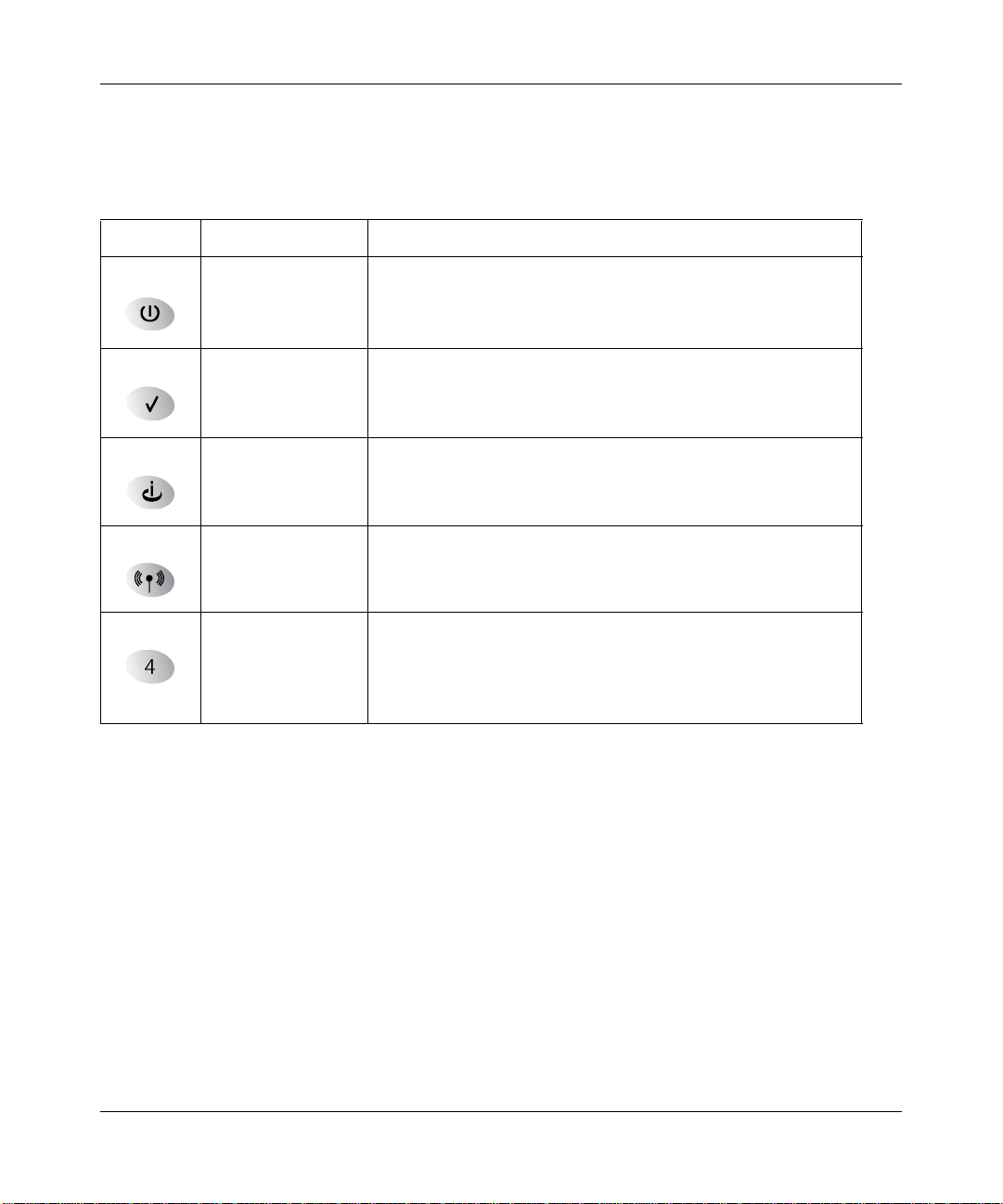
You can use the LEDs to verify various conditions. Table 1 -1 lists and describes each LED on the
front panel of the router. These LEDs are green when lit.
Table 1-1. LED Descriptions
Label Activity Description
Power On
Off
Test On
Off
Internet Blink -- Amber
On -- Green
Blink -- Green
Wireless On Indicates that the Wireless port is initialized.
LAN On (Green)
Blink (Green)
On (Amber)
Blink (Amber)
Off
Power is supplied to the router.
Power is not supplied to the router.
The system is initializing.
The system is ready and running.
Indicates ADSL training.
The Internet port has detected a link with an attached device.
Data is being transmitted or received by the Internet port.
The Local port has detected link with a 100 Mbps device.
Data is being transmitted or received at 100 Mbps.
The Local port has detected link with a 10 Mbps device.
Data is being transmitted or received at 10 Mbps.
No link is detected on this port.
Introduction 1-7
Page 22
Reference Manual for the Model DG824M Wireless ADSL Modem Gateway
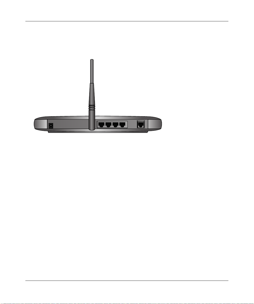
The Gateway’s Rear Panel
The rear panel of the DG824M Wireless ADSL Modem Gateway (Figure 1-2) contains port
connections.
Figure 1-2: DG824M Rear Panel
Viewed from left to right, the rear panel contains the following elements:
• AC power adapter outlet
• Factory Default Reset push button
• Wireless antenna
• Four Local Ethernet RJ-45 ports for connecting the gateway to the local computers
• ADSL port for connecting the gateway to an ADSL line
1-8 Introduction
Page 23

Chapter 2
Connecting the Gateway to the Internet
This chapter describes how to set up the gateway on your Local Area Network (LAN), connect to
the Internet, how to configure your DG824M Wireless ADSL Modem Gateway for Internet access
using the Setup Wizard, or how to manually configure your Internet connection.
What You Will Need Before You Begin
You need to prepare these three things before you can establish an Internet connection through
your gateway:
1. The gateway connecte d to an ADSL line and a c omputer proper ly con nected to the ga teway a s
explained below.
2. Active Internet service such as that provided by an ADSL account.
3. The Internet Service Provider (ISP) configuration information for your DSL account.
Cabling Requirements
The built-in ADSL modem of the DG824M gateway connects to the Internet via your telephone
line using standard twisted-pair telephone cables.
Note: Do not connect the DG824M to the ADSL line through a microfilter unless the microfilter
is specifically designed for this purpose. Doing so will prevent the built-in DSL modem in the
DG824M from establishing a connection to the Internet. If you have any doubts about this, it is
recommended that you connect the DG824 directly to the ADSL line.
The DG824M gateway connects to your LAN via twisted-pair Ethernet cables.
Connecting the Gateway to the Internet 2-1
Page 24

Reference Manual for the Model DG824M Wireless ADSL Modem Gateway
Computer Hardware Requirements
To use the DG824M gateway on your network, each computer must have an installed Ethernet
Network Interface Card (NIC) and an Ethernet cable, or a 802.11b wireless adapter. If the
computer will connect to your networ k at 100 Mbps, you must use a Category 5 (CAT5) cable such
as the one provided with your gateway.
LAN Configuration Requirements
For the initial connection to the Internet and configuration of your gateway, you will need to
connect a computer to the gat eway which is set t o automat icall y get it s TCP/IP con figur ation from
the gateway via DHCP.
Note: Please refer to Appendix C, “Preparing Your Network for assistance with DHCP
configuration.
Internet Configuration Requirements
Depending on how your ISP set up your Internet account, you will need one or more of these
configuration parameters to connect your gateway to the Internet:
• VPI/VCI parameters
• Multiplexing Method
• Host and Domain Names
• ISP Login Name and Password
• ISP Domain Name Server (DNS) Addresses
• Fixed or Static IP Address
Where Do I Get the Internet Configuration Parameters?
There are several ways you can gather the required Internet connection information.
• Your ISP shou ld h ave p rovi de d you with all the information ne eded to c onne ct to the Internet.
If you cannot locate this information, you can ask your ISP to provide it or you can try one of
the options below.
• If you have a computer already connected using the active Internet access account, you can
gather the configuration information from that computer.
2-2 Connecting the Gateway to the Internet
Page 25

Reference Manual for the Model DG824M Wireless ADSL Modem Gateway
• For Windows 95/98/ME, open the Network control panel, select the TCP/IP entry for the
Ethernet adapter, and click Properties.
• For Windows 2000/XP, open the Local Area Network Connecti on, select the TCP/IP entry
for the Ethernet adapter, and click Properties.
• For Macintosh computers, open the TCP/IP or Network control panel.
• You may also re fer to the DG824M Resour c e CD for the NETGEAR Router ISP Gui de which
provides Internet connection information for many ISPs.
Once you locate your Internet configu ration par ameters , you may want to rec ord them on the page
below according to the instructions in “Record Your Internet Connection Information” on page
2-4.
Connecting the Gateway to the Internet 2-3
Page 26

Reference Manual for the Model DG824M Wireless ADSL Modem Gateway
Procedure 2-1: Record Your Internet Connection Information
Print this page. Fill in the configuration parameters from your Internet Service Provider (ISP).
ISP Multiplexing Method and Virtual Circuit Number: The default settings of your DG824M
Wireless ADSL Modem Gateway will work fine for most ISPs. However, some ISPs use a specific
Multiplexing Method or a Virtual Circuit Number for either the VPI or VCI. If your ISP provided
you with a specific Multiplexing Method or VPI/VCI number, then fill in the following:
Multiplexing Method, circle one: LLC-based or VC-based
VPI: ________
ISP Login Name: The login name an d pas swor d ar e ca se s ens itive and must be entered exact ly as
given by your ISP. Some ISPs use your full e -mail addr ess as the l ogin na me. The Ser vice Na me is
not required by all ISPs. If you connect using a login name and password, then fill in the
following:
A number between 0 and 255. VCI: ___________ A number between 1and 65535.
Login Name: ______________________________
Service Name: _____________________________
Fixed or Static IP Address: If you have a static IP address, record the following information. For
example, 169.254.141.148 could be a valid IP address.
Fixed or Static Internet IP Address: ______
Gateway IP Address: ______ . ______ . ______ . ______
Subnet Mask: ______ . ______ . ______ . ______
ISP DNS Se rver Addresses: If you were given DNS server addresses, fill in the following:
Primary DNS Server IP Address: ______
Secondary DNS Server IP Address: ______ . ______ . ______ . ______
Host and Domain Names: Some ISPs use a specific host or domain name like CCA7324-A or
home. If you haven’t been given host or domain names, you can use the following examples as a
guide:
• If your main e-mail account with your ISP is aaa@yyy.com, then use aaa as your host name.
Your ISP might call this your account, user, host, computer, or system name.
• If your ISP’s mail server is mail.xxx.yyy.com, then use xxx.yyy.com as the domain name.
ISP Host Name: _________________________
. ______ . ______ . ______
. ______ . ______ . ______
Password: ____________________________
ISP Domain Name: _______________________
2-4 Connecting the Gateway to the Internet
Page 27

Reference Manual for the Model DG824M Wireless ADSL Modem Gateway
Connecting the DG824M Wireless ADSL Modem Gateway to Your LAN
This section provides instructions for connecting the DG824M gateway.
Note: The Resource CD included with your gateway contains an animated Installation Assistant to
help you through this procedure.
Procedure 2-2: Connecting the Gateway
There are three steps to connecting your firewall:
1. Connect the gateway to your ADSL line
1. Connect the gateway to the computers on your network
2. Log in to the gateway
3. Connect to the Internet
Follow the steps below to connect your gateway to your network. You can also refer to the
Resource CD included with your gateway which contains an animated Installation Assistant to
help you through this procedure.
Connecting the Gateway to the Internet 2-5
Page 28
Reference Manual for the Model DG824M Wireless ADSL Modem Gateway
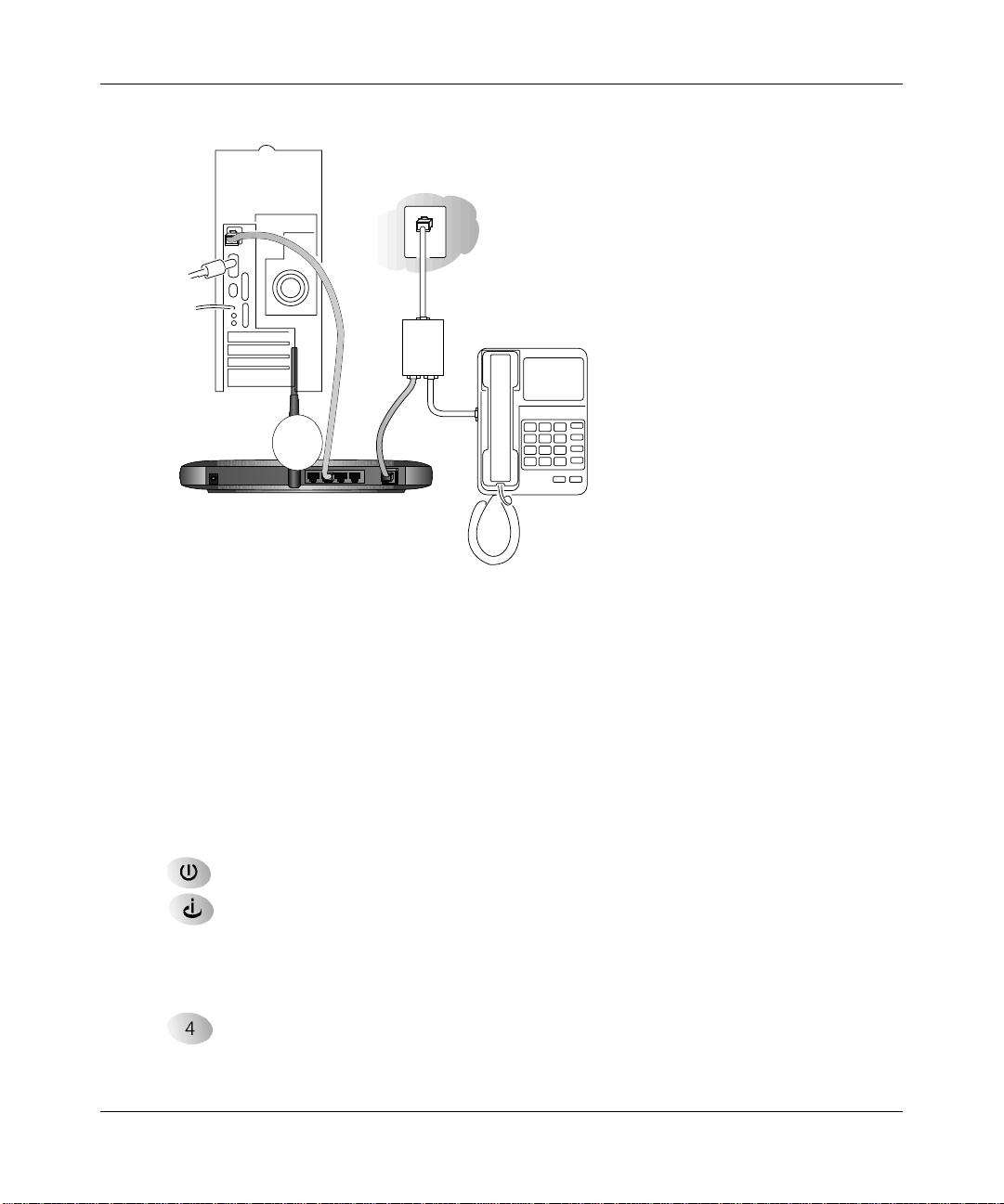
1.
Connect the DG824M.
a. Turn off your computer.
b. Connect the cable (A) from the DG824M ADSL port to your ADSL outlet, being sure to
properly connect the wires as shown in the illustration below.
Line
Phone
DSL
A
Wireless ADSL Modem Gateway DG824M
Figure 2-1: Connect the ADSL Cable
Note: The illustration above depicts a microfilter splitter specifically designed to enable a
phone and ADSL modem to connect to the same phone line wall jack outlet. Do not connect
the DG824B to your ADSL line with a microfilter unless the microfilter specifically designed
for that purpose. Doing so will prevent the modem from establishing a connection to the
Internet. If you have any doubts about this, use only a phone cord to connect the DG824B to
the ADSL wall jack outle t.
2-6 Connecting the Gateway to the Internet
Page 29
Reference Manual for the Model DG824M Wireless ADSL Modem Gateway
c.
Connect the Ethernet cable (B) from your DG824M’s LAN port to a computer.
Line
Phone
DSL
B
Wireless ADSL Modem Gateway DG824M
Figure 2-2: Connect the gateway to a computer
Note: The DG824M gateway incorpor ates Auto UplinkTM technology . Eac h Ethernet LAN
port will automatically sense whether the cable plugged into the port should have a
'normal' connection (e.g. connecting to a PC) or an 'uplink' connection (e.g. connecting to
a switch or hub). That port will then configure itself to the correct configuration. This
feature also eliminates the need to worry about crossover cables, as Auto Uplink will
accommodate either type of cable to make the right connection.
d. Connect the power adapter to the gateway and plug it in to a power outlet. Verify the
following:
The power light is lit after turning on the gateway.
The ADSL link light is solid green, indicating a link has been established to the
cable network.
e. Now, turn on your computer. If software usually logs you in to your Internet connection,
do not run that software or cancel it if it starts automatically.
The local lights are lit for any connected computers.
Connecting the Gateway to the Internet 2-7
Page 30
Reference Manual for the Model DG824M Wireless ADSL Modem Gateway
Note: For instructions on co nnec ti ng comput er s t o the DG824M via wireless links, please
see the Chapter 3, “Wireless Configuration”.
2. Log in to the DG824M.
Note: If you usually run software to log in to your Internet connection, do not run that
software.
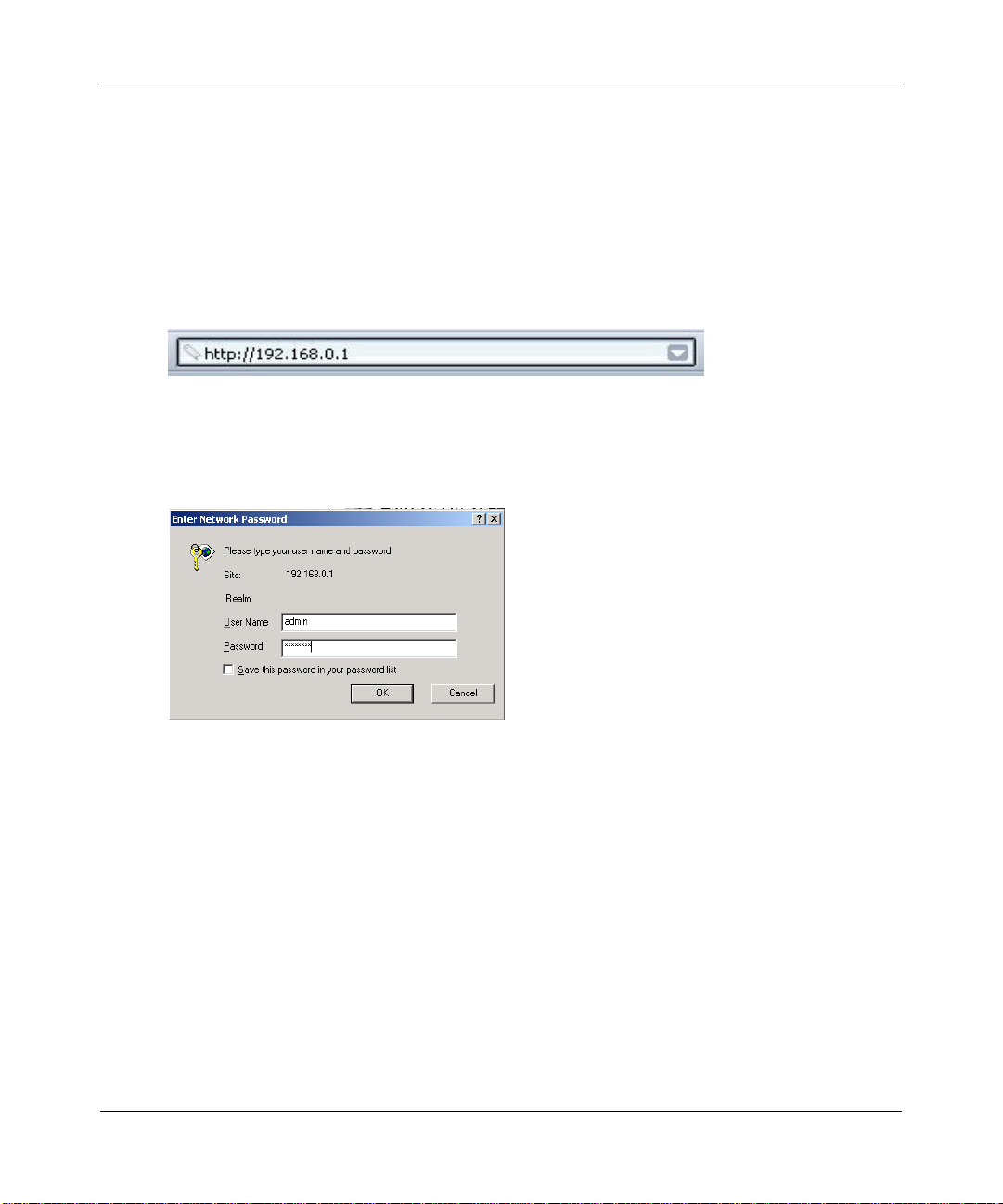
a. Connect to the ga teway by typing http://192.168.0.1 in the address field of Internet
Explorer or Netscape
Figure 2-3: Log in to the gateway
®
Navigator.
A login window opens as shown below:
Figure 2-4: Login window
For security reasons, the gateway has its own user name and password. When prompted,
b.
enter admin for the gateway User Name and password for the gateway Password, both i n
lower case letters.
Note: The user name and password are not the same as any user name or password you
may use to log in to your Internet connection.
2-8 Connecting the Gateway to the Internet
Page 31

Reference Manual for the Model DG824M Wireless ADSL Modem Gateway
3. Connect to the Internet.
Figure 2-5: Setup Wizard
You are now connected to the gateway. If you do not see the menu above, click the Setup
a.
Wizard link on the upper left of the main menu. Click the Yes button in the Setup Wizard.
b. Please click Next to follow the steps in the Setup Wizard to input the configuration
parameters from your ISP to connect to the Internet.
Note: If you were unable to connect to the gateway, please refer to troubleshooting procedures in
“Basic Functioning” on page 7-1.
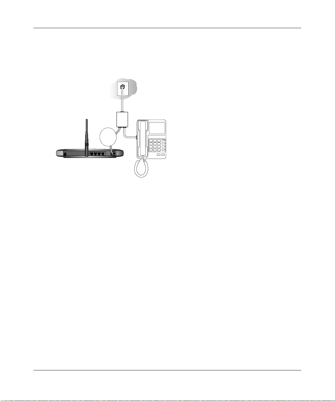
4. Connect an ADSL microfilter to your phone.
a. ADSL transmissions use your phone wires and can interfere with the quality of your
phone service. A microfilter eliminates such problems. Depending on the country of
purchase, a microfilter may be included in your DG824M package. Locate a suitable
microfilter .
b. Connect the microfilter to your phone line between the phone set and the phone line wall
outlet. Each phone set requires a microfilter.
Note: Improperly connecting a microfilter to your DG824M gateway will block your
ADSL connection.
Connecting the DG824M to the Internet
The gateway is now properly attached to your network. You are now ready to configure your
gateway to connect to th e Inte rnet. There a re two ways you can con figur e your gat eway to connect
to the Internet:
Connecting the Gateway to the Internet 2-9
Page 32

Reference Manual for the Model DG824M Wireless ADSL Modem Gateway
• Let the DG824M auto-detect the type of Internet connection you have and configure it.
• Manually choose which type of Internet connection you have and configure it.
These options are described below. In either case, unless your ISP automatically assigns your
configuration automatically via DHCP, you will need the configuration parameters from your ISP
you recorded in “Record Your Internet Connection Information” on page 2-4.
Procedure 2-3: Auto-Detecting Your Internet Connection Type
The Web Configuration Manager built in to the gateway contains a Setup Wizard that can
automatically determine your network connection type.
1. If your gateway has not yet been configured, the Setup Wizard shown in Figure 2-6 should
launch automatically.
Note: If, instead of the Setup Wizard menu, the main menu of the gateway’s Configuration
Manager as shown in Figure 2-11 appears, click the Setup Wizard link in the upper left to
bring up this menu.
When the Wizard launches, select Yes in the menu below to allow the gateway to
automatically determine your connection.
Figure 2-6: Built-in Web-based Configuration Manager Setup Wizard
Click Next
2.
The Setup Wizard will now check for the following connection types:
• Dynamic IP assignment
• A login protocol such as PPPoE or PPPoA
2-10 Connecting the Gateway to the Internet
Page 33

Reference Manual for the Model DG824M Wireless ADSL Modem Gateway
• Fixed IP address assignment
Next, the Setup Wizard will report which connection type it has discovered, and then display
the appropriate configuration menu. If the Setup Wizard finds no connection, you will be
prompted to check the physical connection between your gateway and the ADSL line. When
the connection is properly made, the gateway’s Internet LED should be on.
The procedures for filling in the configuration menu for each type of connection follow below.
Procedure 2-4: Wizard-Detected PPPoE Login Account Setup
If the Setup Wizard determines that your Internet service account uses a login protocol such as
PPP over Ethernet (PPPoE), you will be directed to a menu like the PPPoE menu in Figure 2-7:
Figure 2-7: Setup Wizard menu for PPPoE login accounts
Enter the PPPoE login user name, password, and Service Name (if required) as provided by
1.
your ISP. These fields are case sensitive.
2. If you wish to change the login timeout, enter a new value in minutes. This dete rmines how
long the gateway keeps the Internet connection active after there is no Internet activity from
the LAN. Entering a timeout value of zero means never log out.
Connecting the Gateway to the Internet 2-11
Page 34

Reference Manual for the Model DG824M Wireless ADSL Modem Gateway
Note: You will no longer need to launch the ISP’s login prog ram on yo ur PC in ord er to acc ess
the Internet. When you start an Internet application, your gateway will automatically log you
in.
3. Domain Name Server (DNS) Address: If you know that your ISP does not automatically
transmit DNS addresses t o the gate way duri ng login, se lect “Use t hese DNS serv ers” and en ter
the IP address of your ISP’s Primary DNS Server. If a Secondary DNS Server address is
available, enter it also.
If you enter an address here, after you finish configuring the gateway, reboot your PCs so
that the settings take effect.
4. Click on Apply to save your settings.
5. Click on the Test button to test your Internet connection. If the NETGEAR website does not
appear within one minute, refer to Chapter 7, “Troubleshooting”.
Procedure 2-5: Wizard-Detected PPPoA Login Account Setup
If the Setup Wizard determines that your Internet service account uses a login protocol such as
PPP over ATM (PPPoA), you will be directed to a menu like the PPPoA menu in Figure 2-7:
Figure 2-8: Setup Wizard menu for PPPoA login accounts
2-12 Connecting the Gateway to the Internet
Page 35

Reference Manual for the Model DG824M Wireless ADSL Modem Gateway
1.
Enter your Login and Password. These fields are case sensitive. If you wish to change the
login timeout, enter a new value in minutes. This determines how long the gat eway keeps the
Internet connection active after ther e is no Internet activity from the LAN. Entering a timeo ut
value of zero means never log out.
Note: You will no longer need to launch the ISP’s login prog ram on yo ur PC in ord er to acc ess
the Internet. When you start an Internet application, your gateway will automatically log you
in.
2. Domain Name Server (DNS) Address:
These parameters may be necessary to access your ISP’s services such as mail or news servers.
If you leave the Domain Name field blank, the gateway will attempt to learn the domain
automatically from the ISP. If this is not successful, you may need t o enter it manually.
If you know that your ISP does not automatically transmit DNS addresses to the gateway
during login, select “Use these DNS servers” and enter the IP address of your ISP’s Primary
DNS Server. If a Secondary DNS Se rver address is available, enter it also .
If you enter an address here, after you finish configuring the gateway, reboot your PCs so
that the settings take effect.
3. Click on Apply to save your settings.
4. Click on the Test button to test your Internet connection. If the NETGEAR website does not
appear within one minute, refer to Chapter 7, “Troubleshooting”.
Connecting the Gateway to the Internet 2-13
Page 36

Reference Manual for the Model DG824M Wireless ADSL Modem Gateway
Procedure 2-6: Wizard-Detected Dynamic IP Account Setup
If the Setup Wizard determines that your Internet service account uses Dynamic IP assignment,
you will be directed to the menu shown in Figure 2-9 below:
Figure 2-9: Setup Wizard menu for Dynamic IP address
Enter your Account Name (may also be called Host Name) and Domain Name. These
1.
parameters may be ne cessary to acc ess your ISP’s services such as mai l or news servers . If yo u
leave the Domain Name field blank, the gateway will attempt to learn the domain
automatically from the ISP. If this is not successful, you may need t o enter it manually.
2. If you know that your ISP does not automatically transmit DNS addresses to the gateway
during login, select “Use these DNS servers” and enter the IP address of your ISP’s Primary
DNS Server. If a Secondary DNS Se rver address is available, enter it also .
A DNS server is a host on the Internet that translates Internet names (such as
www .netge ar.com) to numeric IP addresses. Typ ical ly your ISP tr ansfe rs the IP add ress of
one or two DNS servers to your gateway during login. If the ISP does not transfer an
address, you must ob tain it fr om the ISP a nd enter it manuall y here. I f you ent er an addr ess
here, you should reboot your PCs after configuring the gateway.
3. The Router’s MAC Address is the Ethernet MAC address that will be used by the gateway on
the Internet port.
2-14 Connecting the Gateway to the Internet
Page 37

Reference Manual for the Model DG824M Wireless ADSL Modem Gateway
If your ISP allows access from only one specific computer’s Ethernet MAC address, select
“Use this MAC address.” The gateway will then capture and use the MAC address of the
computer that you are now using. You must be using the one computer that is allowed by the
ISP. Otherwise, you can type in a MAC address.
Note: Some ISPs will register the Ethernet MAC address of the network interface card in
your PC when your account is first opened. They will then only accept traffic from the
MAC address of that PC. T his feature allows your gateway to mas querade as th at PC by
using its MAC address.
4. Click on Apply to save your settings.
5. Click on the Test button to test your Internet connection. If the NETGEAR website does not
appear within one minute, refer to Chapter 7, “Troubleshooting””.
Procedure 2-7: Wizard-Detected Fixed IP (Static) Account Setup
If the Setup Wizard determines that your Internet service account uses Fixed IP assignment, you
will be directed to the menu shown in Figure 2-10 below:
Figure 2-10: Setup Wizard menu for Fixed IP address
Enter your assigned IP Address, Subnet Mask, and the IP Address of your ISP’s gateway
1.
router. This information should have been provided to you by your ISP. You will need the
configuration parameters from your ISP you recorded in “Record Your Internet Connection
Information” on page<$chapnum>4.
Connecting the Gateway to the Internet 2-15
Page 38

Reference Manual for the Model DG824M Wireless ADSL Modem Gateway
2.
Enter the IP address of your ISP’s Primary DNS Server. If a Secondary DNS Server address is
available, enter it also.
A DNS servers are requi red to p erform th e functi on of tra nslatin g an Inte rnet name such as
www .netgear.com to a numeric IP addres s. For a fixed IP address c onfi gur ation, you must
obtain DNS server addresses from your ISP and enter them manually here. You should
reboot your PCs after configuring the gateway for these settings to take effect.
3. Click on Apply to save the settings.
4. Click on the Test button to test your Internet connection. If the NETGEAR website does not
appear within one minute, refer to Chapter 7, “Troubleshooting”.
Testing Your Internet Connection
After completing the Internet connection configuration, your can test your Internet connection.
Log in to the gateway, then, from the Setup Basic Settings link, click on the Test button. If the
NETGEAR website does not appear within one minute, refer to Chapter 7, “Troubleshooting”.
Your gateway is now configured to provide Internet access for your network. Your gateway
automatically connects to the Internet when one of your computers requires access. It is not
necessary to run a dialer or login application such as Dial-Up Networking or Enternet to connect,
log in, or disconnect. These functions are performed by the gateway as needed.
To access the Internet from any computer connected to your gateway, launch a browser such as
Microsoft Internet Explorer or Netscape Navigator. You should see the gateway’s Internet LED
blink, indicating communication to the ISP. The browser should begin to display a Web page.
The following chapters describe how to configure the Advanced features of your gateway, and
how to troubleshoot problems that may occur.
2-16 Connecting the Gateway to the Internet
Page 39

Reference Manual for the Model DG824M Wireless ADSL Modem Gateway
Manually Configuring Your Internet Connection
You can manually configure your gateway using the menu below, or you can allow the Setup
Wizard to determine your configuration as described in the previous section.
Figure 2-11: Browser-based configuration Basic Settings menu
Connecting the Gateway to the Internet 2-17
Page 40

Reference Manual for the Model DG824M Wireless ADSL Modem Gateway
Procedure 2-8: Manual Configuration
You can manually configure the gateway in the Basic Settings menu shown in Figure 2-11 using
these steps:
1. If your ISP ADSL service req uir es set ti ng th e Mu lt ipl ex ing Method a nd VPI/ VCI par amet er s,
click on the ADSL Settings link from the main menu, fill in the settings your ISP provided,
and click Apply. Usually the default settings will work fine and you can skip this step.
2. Click the Basic Settings link on t he Setup menu. If your Int ernet connect ion does not req uire a
login, fill in the settings a ccording to the instruction s below. If your Internet con nection does
require a login, click Yes, and skip to step 3.
Select Yes if you normally must launch a login program such as Enter net or W inPOET in order
to access the Internet.
Note: You will no longer need to launch the ISP’s login prog ram on yo ur PC in ord er to acc ess
the Internet. When you start an Internet application, your gateway will automatically log you
in.
a. Enter your Account Name (may also be called Host Name) and Domain Name.
These parameters may be necessary to access your ISP’s services such as mail or news
servers. These fields are case sensitive.
b. If you wish to change the login timeout, enter a new value in minutes. This dete rmines
how long the gateway keeps the Internet connection active after there is no Internet
activity from the LAN. Entering an Idle Timeout value of zero means never log out.
c. Domain Name Server (DNS) Address:
If you know that your ISP does not automatically transmit DNS addresses to the gateway
during login, select “Use these DNS servers” and enter the IP address of your ISP’s
Primary DNS Server. If a Secondary DNS Server address is available, enter it also
3. If your Internet con nection doe s requir e a login, c lick Yes at the top of the Basic Set tings menu
and fill in the settings according to the instructions below.
a. Enter your Account Name (may also be called Host Name) and Domain Name.
These parameters may be necessary to access your ISP’s services such as mail or news
servers.
2-18 Connecting the Gateway to the Internet
Page 41

Reference Manual for the Model DG824M Wireless ADSL Modem Gateway
b.
Internet IP Address:
If your ISP has assigned you a permanent, fixed (static) IP address for your PC, select
“Use static IP address”. Enter the IP address that y our ISP assigned. Also enter the
netmask and the Gateway IP address. The Gateway is the ISP’s router to which your
gateway will connect.
c. Domain Name Server (DNS) Address:
If you know that your ISP does not automatically transmit DNS addresses to the gateway
during login, select “Use these DNS servers” and enter the IP address of your ISP’s
Primary DNS Server. If a Secondary DNS Server address is available, enter it also.
A DNS server is a host on the Internet that translates Internet names (such as
www .netge ar.com) to numeric IP addresses. Typ ical ly your ISP tr ansfe rs the IP add ress of
one or two DNS servers to your gateway during login. If the ISP does not transfer an
address, you must ob tain it fr om the ISP a nd enter it manuall y here. I f you ent er an addr ess
here, you should reboot your PCs after configuring the gateway.
d. Gateway’s MAC Address:
This section determines the Ethernet MAC address th at will be used by the gateway on the
Internet po rt. Some ISPs will register the Ethernet MAC addres s of the network interface
card in your PC when your account is fir st open ed. They wil l then only acce pt tra f fic f rom
the MAC address of that PC. This feature allows your gateway to masquerade as that PC
by “cloning” its MAC address.
To change the MAC address, select “Use this Computer’s MAC address.” The gateway
will then capture and use the MAC addres s of the PC t hat you are now us in g. You must be
using the one PC that is allowed by the ISP. Or, select “Use this MAC address” and enter
it.
4. Click Apply to save your settings.
5. Click on the Test button to test your Internet connection.
If the NETGEAR website does not appear within one minute, refer to Chapter 7,
“Troubleshooting”.
Connecting the Gateway to the Internet 2-19
Page 42

Reference Manual for the Model DG824M Wireless ADSL Modem Gateway
2-20 Connecting the Gateway to the Internet
Page 43

Chapter 3
Wireless Configuration
This chapter describes how to configure the wireless features of your DG824M Wireless ADSL
Modem Gateway.
Considerations For A Wireless Network
In planning your wireless network, you should consider the level of security required. You should
also select the physical placement of your gateway in order to maximize the network speed. For
further information on wireless networking, refer to “Wireless Networking” in Appendix B,
“Network and Routing Basics.”
Implement Appropriate Security
Unlike wired network data, your wireless data transmissions can extend beyond your walls and
can be received by anyone with a compatible adapter. For this reason, use the security features of
your wireless equipment. As a minimum precaution, change the SSID setting of all devices on
your network from the factory setting to a unique password. Restricting access by MAC address
filtering adds another obstacle against unwanted hosts joining your network. To hinder a
determined eavesdropper, you should enable Wired Equivalent Privacy (WEP) data encryption.
However, there may be a significant degradation of the data throughput on the wireless link when
WEP is enabled.
Observe Placement and Range Guidelines
The operating distance or range of your wireless connection can vary significantly based on the
physical placement of the wireless gateway.
Wireless Configuration 3-1
Page 44

Reference Manual for the Model DG824M Wireless ADSL Modem Gateway
Note: Failure to follow these guidelines can result in significant performance
degradation or inability to wirelessly connect to the router.
For best results, place your gateway:
• Near the center of the area in which you r PCs will operate.
• In an elevated location such as a high shelf.
• Away from potential sources of interference, such as PCs, microwaves, and 2.4 GHz cordless
phones.
• Away from large me tal surfaces.
Wireless Settings
To configure the Wireless interface of your gateway, click the Wireless link in the main menu of
the browser interface. The Wireless Settings m enu will appear, as shown below:
Figure 3-1: Wireless Settings menu
In the Wireless Network section are the following paramete rs:
3-2 Wireless Configuration
Page 45

Reference Manual for the Model DG824M Wireless ADSL Modem Gateway
• Identification.
— Regulatory Domain. This field displays the region of operation for which the wireless
interface is intended. It may not be legal to operate the gateway in a region oth er than the
region shown here.
— Station Name. The gateway model number.
— SSID (Service Set ID). This is also known as the wireless network name. Enter a value of
up to 32 alphanu meric charac ters. The same SSID must be a ssigne d to all wirel ess de vices
in your network. The default SSID is Wireless.
• Options.
— Channel No. This field determines which operating frequency will be used. It should not
be necessary to change the wireless channel unless you notice interference problems with
another nearby access point.
— WEP Status. Identifies the WEP options c onfigured.
• Access Point.
— All wireless stations. Any wireless station can connect.
— Trusted PCs only. Only PCs with MAC address which you have specified can connect.
Procedure 3-1: Configuring Basic Wireless Network Settings
1. Choose an SSID for the ga teway and all wireless PCs
Devices on an 802.11b wireless network all share the same network name, or Service Set
Identificatier (SSID). The first step in configuring your wireless network is to choose a secure
value for your wireless network’s SSID. In the SSID box, enter a value of up to 32
alphanumeric characters. This same SSID must be entered in the configuration of all PCs and
devices connecting to this wireless network. The default SSID is Wireless.
Note: The SSID of any wireless access adapters must match the SSID you configure in
the DG824M Wireless ADSL Modem Gateway. If they do not match, you will not get a
wireless connection to the DG824M.
2. Set the Region of operation.
Select the geopgraphic region in which the wireless interface will operate. This setting
determines what radio fre quenci es wil l be avai labl e. It may n ot be l egal to o perat e the gat eway
in a region other than the region shown here.
Wireless Configuration 3-3
Page 46

Reference Manual for the Model DG824M Wireless ADSL Modem Gateway
3.
Set the Channel.
This field determines which operating frequency will be used. It should not be necessary to
change the wireless channel unless you notice interference problems with another nearby
wireless router or access point. Select a channel that is not being used by any other wireless
networks within several hundred feet of your gateway. The default channel is 6.
4. For initial configuration and test, make sure that the Wireless Card Access List is set to
Everyone and that Encryption Strength is set to Disabled.
Note: These settings are not recommended for normal operation, but should be set initially to
test basic wireless connectivity.
5. Click Apply to save your changes.
Note: If you are configuring the gateway from a wireless PC and you change the
gateway’ s SSI D, channel, or WEP set tings, you wi ll lose your wir eless conn ection when
you click on Apply. You must then change the wireless settings of your PC to match t h e
gateway’s new settings.
6. Configure and test your PCs for wireless connectivity.
Program the wireless adapter of your PCs to have the same SSID and channel that you
configured in the router. Check that they have a wireless link and are able to obtain an IP
address by DHCP from the gateway.
Once your PCs have basic wireless connectivity to the gateway, then you can configre the
advanced wireless security functions of the gateway.
Using the Wireless Access by MAC Address Feature
By default, any wirele ss PC tha t is conf igured wit h the cor rect SSID wi ll be allowed access to your
network. For increased security, you can restrict access to the wireless network to only allow
specific PCs based on their MAC addresses. You can allow access by:
The Trusted PCs window displays a list of MAC addresses that will be allowed to connect to the
gateway. These PCs must also be configured with SSID and WEP settings which match those of
the DG824M.
3-4 Wireless Configuration
Page 47

Reference Manual for the Model DG824M Wireless ADSL Modem Gateway
Procedure 3-2: Restricting Wireless Access by MAC Address
To restrict access based on MAC addresses, follow these steps:
1. From the W i re less Settings menu, clic k th e Trusted PCs but to n to display the W i reless Access
menu, shown below:
Figure 3-2. Wireless Access menu
2.
Click the Add button.
3. Enter the MAC address of the authorized PC. The MAC address is usually printed on the
wireless card, or it may appear in th e gateway’s DHCP table.
You can copy and paste the MAC addresses from the gateway’s Attached Devices menu into
the MAC Address box of this menu. To do this, configure each wireless PC to obtain a
wireless link to the gateway. The PC should then appear in the Attached Devices menu.
Note: If you are configuring th e gate way fro m a wire less PC whose MAC add re ss is not
in the Trusted PC list, and you select Trusted PCs only, you will lose your wireless
connection when you click on Apply. You must then access the gateway from a wired
PC to make any further changes.
4. Click Add to save your entry.
5. Return to the Wireless Settings m enu, select Trusted PCs only, then click Apply.
To delete a MAC address from the table, c lick on it to select it, then click the Delete button.
To edit a MAC address from the table, click on it to select it, then click the Edit or Delete button.
Wireless Configuration 3-5
Page 48

Reference Manual for the Model DG824M Wireless ADSL Modem Gateway
Configuring Wired Equivalent Privacy (WEP)
Figure 3-3. Wireless WEP menu
In the Wireless Settings menu you can configure WEP data encryption using the following
parameters:
• Authentication Type
Normally this can be left at the default value of Automatic. If that fails, select the appropriate
value - Open System or Shared Key. Check your wireless card's documentation to see what
method to use.
• Encryption Strength
The previous settings have determined which PCs will be allowed to access your wireless
network, but have not added any protection from eavesdropping. With this setting, you can
choose to have your data encrypted between the PCs and the gateway. Your choices are:
—Disable
No encryption will be applied. This setting is useful for troubleshooting your wireless
connection, but leaves your wireless data fully exposed.
— 64 or 128 bit WEP
Wireless Equivalent Privacy encryption will be applied. WEP provides some degree of
privacy, but can be defeated without great difficulty.
—Keys
If WEP is enabled, you can manually or automatically program the four data encryption
keys. These values must be identical on all PCs and Access Points in your network.
3-6 Wireless Configuration
Page 49

Reference Manual for the Model DG824M Wireless ADSL Modem Gateway
• Automatic - Enter a word or group of printable characters in the Passphrase box and
click the Generate button. The keys will be automatically populated with key values.
For 64-bit encryption, all four keys are generated from a single passphrase. With
128-bit encryption, each key can be generated with a different pasphrase.
• Manual - Enter ten hexadecimal digits (any combination of 0-9, a-f, or A-F)
Select which of the four keys will be active.
Be sure to click Apply to save your settings in this menu.
Configuring WEP (Wired Equivalent Privacy)
If you have chosen to use WEP instead of IPSec, go to the Wireless Settings menu, click the
Encryption Strength box and select either 64 Bit WEP or 128 Bit WEP. The Wireless Settings
menu will display WEP setting fields, as shown below.
Figure 3-4. Wireless Settings menu, WEP selected
When WEP is enabled, you can manu al ly or automatically program the four data encryptio n keys.
These values must be identical on all PCs and Access Points in your network.
• Manual - Enter 10 hexadecimal digits if 64 Bit WEP or 26 digits for 128 Bit WEP.
Hexadecimal digits are 0-9, a-f, or A-F.
Wireless Configuration 3-7
Page 50

Reference Manual for the Model DG824M Wireless ADSL Modem Gateway
• Automatic - Enter a word or group of printable characters in the Passphrase box and click the
Generate button.
Select which of the four keys will be active.
Click Apply to save any settings from this menu.
3-8 Wireless Configuration
Page 51

Chapter 4
Protecting Your Network
This chapter describes how to use the basic firewall features of the DG824M Wireless ADSL
Modem Gateway to protect your network.
Protecting Access to Your DG824M Wireless ADSL Modem Gateway
For security reasons, the gateway has its own user name and password. Also, after a period of
inactivity for a set length of time, the administrator login will automatically disconnect. When
prompted, enter admin for the gateway User Name and password for the gateway Password. Y ou
can use procedures below to change the gateway's password and the amount of time for the
administrator’s login timeout.
Note: The user name and password are not the same as any user name or password your may use
to log in to yo ur Internet con nection.
NETGEAR recommends that you change this password to a more secure password. The ideal
password should contain no dictionary words from any language, and should be a mixture of both
upper and lower case letters, numbers, and symbols. Your password can be up to 30 characters.
Procedure 4-1: Changing the Built-In Password
1. Log in to the gateway at its default LAN address of http://192.168.0.1 with its default User
Name of admin, default password of password, or using whatever Password and LAN
address you have chosen for the gateway.
Figure 4-1: Log in to the gateway
Protecting Your Network 4-1
Page 52

Reference Manual for the Model DG824M Wireless ADSL Modem Gateway
2.
From the Main Menu of the browser interface, under the Maintenance heading, select Set
Password to bring up the menu shown in Figure 4-2.
Figure 4-2: Set Password menu
3.
To change the password, first enter the old password, and then enter the new password twice.
4. Click Apply to save your changes.
Note: After changing the password, you will be required to log in again to continue the
configuration.
If you have backed up the gateway settings previously, you should do a new
backup so that the saved settings file includes the new password.
Procedure 4-1: Changing the Administrator Login Timeout
For security, the admini strator's login to the gateway configuration will timeout after a period of
inactivity. To change the login timeout period:
1. In the Set Password menu, type a number in ‘Administrator login times out’ field.The
suggested default value is 5 minutes.
2. Click Apply to save your changes or click Cancel to keep the current period.
4-2 Protecting Your Network
Page 53

Reference Manual for the Model DG824M Wireless ADSL Modem Gateway
Configuring Basic Firewall Services
Basic firewall services you can configure include access blocking and scheduling of firewall
security. These topics are presented below.
Blocking Keywords, Sites, and Services
The gateway provides a variety of options for blocking Internet based content and
communications services.
objectionable content from reaching your PCs. The Model RT311 router allows you to control
access to Internet content by screening for keywords within Web addresses. Key content filtering
options include:
• Blocks access from your LAN to Internet locations that you specify as off-limits.
• Keyword blocking of newsgroup names.
• Outbound Services Blocking limits access from your LAN to Internet locations or services
that you specify as off-limi ts.
• Denial of Service (DoS) protection. Automatically detects and thwarts Denial of Service
(DoS) attacks such as Ping of Death, SYN Flood, LAND Attack and IP Spoofing.
With its content filtering feature, the DG824M gateway prevents
• Blocks unwanted traffic from the Internet to your LAN.
The section below explains how to configure your
gateway to perform these functions.
Procedure 4-2: Block Keywords and Sites
The DG824M gateway allows you to re st ri ct access to Internet content ba sed on functions such as
Java or Cookies, Web addresses and Web address keywords.
1. Log in to the gateway at its default LAN address of http://192.168.0.1 with its default User
Name of admin, default password of password, or using whatever Password and LAN
address you have chosen for the gateway.
Protecting Your Network 4-3
Page 54

Reference Manual for the Model DG824M Wireless ADSL Modem Gateway
2.
Click on the Block Sites link of the Security menu.
Figure 4-3: Block Sites menu
3.
To enable keyword blocking, check “Turn keyword blocking on”, enter a keyword or domain
in the Keyword box, click Add Keyword, then click Apply.
Some examples of Keyword application follow:
• If the keyword “XXX” is specified, the URL <http://www.badstuff.com/xxx.html> is
blocked, as is the newsgroup alt.pictures.xxx.
• If the keyword “.com” is specifi ed, only websit es with other domai n suffixe s (such as .edu
or .gov) can be viewed.
• Enter the keyword “.” to block all Internet browsing access.
Up to 32 entries are supported in the Keyword list.
4. To delete a keyword or domain, sel ect it from the l is t, cl i ck Del et e Keywor d, t hen cl i ck Appl y.
5. To specify a Trusted User, enter that PC’s IP address in the Trusted User box and click Apply.
You may specify one Trusted User, which is a PC that will be exempt from blocking and
logging. Since the Trusted User will be identified by an IP address, you should configure that
PC with a fixed IP address.
4-4 Protecting Your Network
Page 55

Reference Manual for the Model DG824M Wireless ADSL Modem Gateway
6.
Click Apply to save your settings.
Rules
Firewall rules are used to bloc k or allow specifi c traf fic passi ng through from one side to the other.
Inbound rules (WAN to LAN) restrict access by outside rs to private re sources, sele ctively allo wing
only specific outside users to access specific resourc es. Outbound rules (LAN to WAN) determine
what outside resources local users can have access to.
A firewall has two defau lt rules, one fo r inbound traffic and one for outbo und. The defa ult ru les of
the DG824M are:
• Inbound: Block all access from outside except responses to requests from the LAN side.
• Outbound: Allow all access from the LAN side to the outside.
You may define ad ditional rul es that will specify exc eptions to t he default rules. By adding cu stom
rules, you can block or allow access based on the service or application, source or destination IP
addresses, and time of day. You can also choose to log traffic that matches or does not match the
rule you have defined.
Protecting Your Network 4-5
Page 56

Reference Manual for the Model DG824M Wireless ADSL Modem Gateway
To access the Rules configuration of the DG824M, click the Rules link on the main menu, then
click Add for either an Outbound or Inbound Service.
Figure 4-4: Rules menu
• To edit an existing rule, select its button on the left side of the table and click Edit.
• To delete an existing ru le, select its button on the left side of the table and click Delete.
• T o move an existing rule to a dif fer ent posit ion in t he table, select its button on the l eft sid e
of the table and click Move. At the script prompt, enter the number of the desired new
position and click OK.
4-6 Protecting Your Network
Page 57

Reference Manual for the Model DG824M Wireless ADSL Modem Gateway
Inbound Rules (Port Forwarding)
Because the DG824M uses Network Address Translation (NAT), your network presents only one
IP address to the Internet, and outside users cannot directly address any of your local computers.
However, by defining an inbound rule you can make a local server (for example, a web server or
game server) visible and available to the Internet. The rule tells the gateway to direct inbound
traffic fo r a particul ar ser vic e to one loc al serve r based on t he desti natio n port number. This is also
known as port forwarding.
Note: Some residential broadband ISP accounts do not allow you to run any server
processes (such as a Web or FTP server) from your location. Your ISP may periodically
check for servers and may suspend your account if it discovers any active services at
your location. If you are unsure, refer to the Acceptable Use Policy of your ISP.
Remember that allowing inbound services opens holes in your firewall. Only enable those ports
that are necessary for your network. Following are two application examples of inbound rules:
Inbound Rule Example: A Local Public Web Server
If you host a public web s erver on your local network, you can define a rule to al l ow inb ound web
(HTTP) requests from any outside IP address to the IP address of your web server at any time of
day. This rule is shown in Figure 4-5:
Figure 4-5: Rule example: A Local Public Web Server
Protecting Your Network 4-7
Page 58

Reference Manual for the Model DG824M Wireless ADSL Modem Gateway
The parameters are:
•Service
From this list, select the application or service to be allowed or blocked. The list already
displays many common services, but you are not limited to these choices. Use the Add
Services menu to add any additional services or applications that do not already appear.
• Action
Choose how you would like this type of traffic to be handled. You can block or allow
always, or you can choos e to bl ock or allo w accor ding to the s chedul e yo u have d efined i n
the Schedule menu.
• Send to LAN Server
Enter the IP address of the PC or Server on your LAN which will receive the
inbound traffic covered by this rule.
• WAN Users
These settings determine which packets are covered by the rule, based on their
source (WAN) IP address. Select the desired option:
• Any All IP addresses are covered by this rule.
• Address range If this opt ion is sel ecte d, you must enter the "S tar t" and "Finish " fiel ds.
• Single address Enter the required address in the "Start" fields.
•Log
You can select whether the traffic will be logged. The choices are:
• Never - no log entries will be made for this service.
• Always - any traffic for this service type will be logged.
• Match - traffic of this type which matches the parameters and action will be logged.
• Not match - traffic of this type which does not match the parameters and action will be
logged.
4-8 Protecting Your Network
Page 59

Reference Manual for the Model DG824M Wireless ADSL Modem Gateway
Inbound Rule Example: Allowing Videoconference from Restricted Addresses
If you want to allow incoming videoconf er enc in g to be initi at ed fr om a rest ri ct ed ra nge of outside
IP addresses, such as from a branch office, you can create an inbound rule. In the example shown
in Figure 4-6, CU-SeeMe connections are allowed only from a specified range of external IP
addresses. In this case, we have also specified logging of any incoming CU-SeeMe requests that
do not match the allowed parameters.
Figure 4-6: Rule example: Videoconference from Restricted Addresses
Considerations for Inbound Rules
• If your external IP address is assigned dynamically by your ISP, the IP address may change
periodically as the DHCP lease expires. Consider using the Dynamic DNS feature in the
Advanced menus so that external users can always find your network.
• If the IP address of the local server PC is assigned by DHCP, it may change when the PC is
rebooted. To avoid this, use the Reserved IP address feature in the LAN IP menu to keep the
PC’s IP address constant.
• Local PCs must access the local server using the PCs’ local LAN addres s ( 192.168.0.11 in the
example in Figure 4-6 above). Attempts by local PCs to access the server using the external
WAN IP address will fail.
Protecting Your Network 4-9
Page 60

Reference Manual for the Model DG824M Wireless ADSL Modem Gateway
Outbound Rules (Service Blocking)
The DG824M allows you to block the use of certain Internet services by PCs on your network.
This is called service blocking or port filtering. You can define an outbound rule to block Internet
access from a local PC based on:
• the IP address of the local PC (source address)
• the IP address of the Internet site being contacted (destination address)
• the time of day
• the type of service being requested (service port number)
Following is an application example of outbound rules:
Outbound Rule Example: Blocking Instant Messenger
If you want to block Instant Me sse nge r usa ge by employees during working hours, you can cr ea te
an outbound rule to block that application from any internal IP address to any external address
according to the schedule that you have created in the Schedule menu. You can also have the
gateway log any attempt to use Instant Messenger during that blocked period.
Figure 4-7: Rule example: Blocking Instant Messenger
4-10 Protecting Your Network
Page 61

The parameters are:
•Service
From this list, select the application or service to be allowed or blocked. The list already
displays many common services, but you are not limited to these choices. Use the Add
Services menu to add any additional services or applications that do not already appear.
• Action
Choose how you would like this type of traffic to be handled. You can block or allow
always, or you can choos e to bl ock or allo w accor ding to the s chedul e yo u have d efined i n
the Schedule menu.
• LAN Users
These settings determine which packets are covered by the rule, based on their
source LAN IP address. Select the desired option:
• Any All IP addresses are covered by this rule.
• Address range If this opt ion is sel ecte d, you must enter the "S tar t" and "Finish " fiel ds.
• Single address Enter the required address in the "Start" fields.
• WAN Users
These settings determine which packets are covered by the rule, based on their
destination WAN IP address. Select the desired option:
Reference Manual for the Model DG824M Wireless ADSL Modem Gateway
• Any All IP addresses are covered by this rule.
• Address range If this opt ion is sel ecte d, you must enter the "S tar t" and "Finish " fiel ds.
• Single address Enter the required address in the "Start" fields.
•Log
You can select whether the traffic will be logged. The choices are:
• Never - no log entries will be made for this service.
• Always - any traffic for this service type will be logged.
• Match - traffic of this type which matches the parameters and action will be logged.
• Not match - traffic of this type which does not match the parameters and action will be
logged.
Protecting Your Network 4-11
Page 62

Reference Manual for the Model DG824M Wireless ADSL Modem Gateway
Order of Precedence for Rules
As you define new rules, they are added to the tables in the Rules menu, as shown in Figure 4-8:
Figure 4-8: Rules table with examples
For any traffic attempting to pass through the firewall, the packet info rmation is sub jected to the
rules in the order shown i n the Rule s Table, beginning at the top and pr oceeding t o the def ault ru les
at the bottom. In some cases, the order of precedence of two or more rules may be important in
determining the dispo sition of a pac ket. The Move button allows you to relo cate a defin ed rule to a
new position in the table.
4-12 Protecting Your Network
Page 63

Reference Manual for the Model DG824M Wireless ADSL Modem Gateway
Services
Services are functions performed by server computers at the request of client computers. For
example, Web servers serve web pages, time servers serve time and date information, and game
hosts serve data about other players’ moves. When a computer on the Internet sends a request for
service to a server computer, the requested service is identified by a service or port number. This
number appears as the destination port number in the transmitted IP packets. For example, a packet
that is sent with destination port number 80 is an HTTP (Web server) request.
The service numbers for many common protocols are defined by the Internet Engineering Task
Force (IETF) and published in RFC1700, “Assigned Numbers.” Service numbers for other
applications are typically chosen from the range 1024 to 65535 by the authors of the application.
Although the DG824M already holds a list of many service port numbers, you are not limited to
these choices. Use the procedure below to create your own service definitions.
Procedure 4-3: Define Services
1. Log in to the gateway at its default LAN address of http://192.168.0.1 with its default User
Name of admin, default password of password, or using whatever Password and LAN
address you have chosen for the gateway.
2. Click on the Services link of the Security menu to display the Services menu shown in
Figure 4-9:
Figure 4-9: Services menu
• To create a new Service, click the Add button.
• To edit an existing Service, select its button on the left side of the table and click Edit.
Protecting Your Network 4-13
Page 64

Reference Manual for the Model DG824M Wireless ADSL Modem Gateway
• To delete an exis ti ng Se rvi ce, select its butt on on the left side of the ta ble and click Delete.
3. Modify the menu shown below for defining or editing a service.
Figure 4-10: Add Services menu
Click Apply to save your changes.
4.
Setting Times and Scheduling Firewall Services
The DG824M gateway uses the Network Time Protocol (NTP) to obta in th e cur re nt ti me and da te
from one of several Netwo rk Time Servers on the Internet. I n order to localize the time for your
log entries, you must select your Time Zone from the list.
Procedure 4-4: Setting Your Time Zone
In order to localize the time for your log entries, you must specify your Time Zone:
1. Log in to the gateway at its default LAN address of http://192.168.0.1 with its default User
Name of admin, default password of password, or using whatever Password and LAN
address you have chosen for the gateway.
4-14 Protecting Your Network
Page 65

Reference Manual for the Model DG824M Wireless ADSL Modem Gateway
2.
Click on the Schedule link of the Security menu to display menu shown below.
Figure 4-11: Schedule Services menu
Select your Time Zone. This setting will be used for the blocking schedule according to your
3.
local time zone and for time-stamping lo g entries.
Check the Daylight Savings Time box if your time zone is currently in daylight savings time.
Note: If your region uses Daylight Savings Time, you must manually check Adjust for
Daylight Savings Time on the first day of Daylight Savings Time, and uncheck it at the end.
Enabling Daylight Savings Time will cause one hour to be added to the standard time.
4. The gateway has a list of publicly available NTP servers. If you would prefer to use a
particular NTP server as the primary server, enter its IP address under Use this NTP Server.
5. Click Apply to save your settings.
Protecting Your Network 4-15
Page 66

Reference Manual for the Model DG824M Wireless ADSL Modem Gateway
Procedure 4-5: Scheduling Firewall Services
If you enabled services blocking in the Block Services menu or Port forwarding in the Ports menu,
you can set up a schedule for when blocking occurs or when access isn't restricted.
1. Log in to the gateway at its default LAN address of http://192.168.0.1 with its default User
Name of admin, default password of password, or using whatever Password and LAN
address you have chosen for the gateway.
2. Click on the Schedule link of the Sec urity menu to di splay men u sho wn above i n the Schedule
Services menu.
3. T o bl ock Inter net s ervic es base d on a s che dule, s elect Every Da y or se lect one or mor e days . If
you want to limit access completely for the selected days, select All Day. Otherwise, to limit
access during certain times for the sele cted da ys, enter St art Blo cking and End Blocking times.
Note: Enter the values as 24-hour time. For example, 10:30 am would be 10 hours and 30
minutes and 10:30 pm would be 22 hours and 30 minutes.
4. Click Apply to save your changes.
4-16 Protecting Your Network
Page 67

Chapter 5
Managing Your Network
This chapter describes how to perform network management tasks with your DG824M Wireless
ADSL Modem Gateway.
Backing Up, Restoring, or Erasing Your Settings
The configuration settings of the DG824M gateway are stored in a configuration file in the
gateway. This file can be backed up to your computer, restored, or reverted to factory default
settings. The procedures below explain how to do these tasks.
Procedure 5-6: Backup the Configuration to a File
1. Log in to the gateway at its default LAN address of http://192.168.0.1 with its default User
Name of admin, default password of password, or using whatever User Name, Password and
LAN address you have chosen for the gateway.
Managing Your Network 5-1
Page 68

Reference Manual for the Model DG824M Wireless ADSL Modem Gateway
2.
From the Maintenance h eadi ng of t he Main Menu, select the Set tings Backup menu as seen in
Figure 5-1.
Figure 5-1: Settings Backup menu
3.
Click Backup to save a copy of the current settings.
4. Store the .cfg file on a computer on your network.
5-2 Managing Your Network
Page 69

Reference Manual for the Model DG824M Wireless ADSL Modem Gateway
Procedure 5-7: Restore a Configuration from a File
1. Log in to the gateway at its default LAN address of http://192.168.0.1 with its default User
Name of admin, default password of password, or using whatever User Name, Password and
LAN address you have chosen for the gateway.
2. From the Maintenance h eadi ng of t he Main Menu, select the Set tings Backup menu as seen in
Figure 5-1.
3. Enter the full path to the f il e on your net work or cli ck the Browse button to browse to the fil e.
4. When you have located the .cfg file, click the Restore button to upload the file to the
gateway.
5. The gateway will then reboot automatically.
Procedure 5-8: Erase the Configuration
It is sometimes desira ble to re store the gat eway to t he fac tory de fault sett ings. Thi s can be done by
using the Erase function.
1. To erase the configuration, from the Maintenance menu Settings Backup link, click the Erase
button on the screen.
2. The gateway will then reboot automatically.
After an erase, the gateway's password will be password, the LAN IP address will be
192.168.0.1, and the router's DHCP client will be enabled.
Note: To restore the factory de fault configuration set tings without knowing the login pass word or
IP address, you must u se the Defaul t Reset butto n on the rear panel o f th e gat eway. See “DG824M
Rear Panel“ on page 1-8.
Upgrading the Gateway’s Firmware
The software of the DG824M gateway is stored in FLASH memory, and can be upgraded as new
software is released by NETGEAR.
Managing Your Network 5-3
Page 70

Reference Manual for the Model DG824M Wireless ADSL Modem Gateway
Upgrade files can be downloaded from NETGEAR's website. If the upgrade file is compressed
(.ZIP file), you must firs t ext ract the bi nary ( .BIN or .IMG) f ile before uploa ding i t to t he gat eway.
Procedure 5-1: Gateway Upgrade
Note: NETGEAR recommends that you back up your configuration before doing a firmware
upgrade. After the upgrade is complete, you may need to restore your configuration settings.
1. Download a nd unzip the new software file from NETGEAR.
The Web browser us ed to upload new firmware into the gateway mus t sup por t HTTP uploads.
NETGEAR recommends using Micros oft In terne t Explor er 5.0 o r Netscape Navigat or 4.7 a nd
above.
2. Log in to the gateway at its default LAN address of http://192.168.0.1 with its default User
Name of admin, default password of password, or using whatever User Name, Password and
LAN address you have chosen for the gateway.
3. From the Main Menu of the browser interface, under the Maintenance heading, select the
Gateway Upgrade heading to display the menu shown in Figure 5-2.
Figure 5-2: Gateway Upgrade menu
In the Gateway Upgrade menu, click the Browse to locate the binary (.BIN or .IMG) upgrade
4.
file.
5. Click Upload.
Note: When uploading soft ware to the gateway, it is importa nt not to i nterrupt the Web browser by
closing the window, clicking a link, or loading a new page. If the browser is interrupted, it may
corrupt the software. When the upload is complete, your gateway will automatically restart. The
upgrade process will typically take about one minute. In some cases, you may need to clear the
configuration and reconfigure the gateway after upgrading.
5-4 Managing Your Network
Page 71

Reference Manual for the Model DG824M Wireless ADSL Modem Gateway
Network Management Information
The DG824M provides a variety of status and usage information which is discussed below.
Viewing Gateway Status and Usage Statistics
From the Main Menu, under Maintenance, select Gateway Status to view the screen in Figure 5-3.
Figure 5-3: Gateway Status screen
The Router Status menu provides a limited amount of status and usage information. From the
Main Menu of the browser interface, under Maintenance, select Router Status to view the status
screen, shown in Figure 5-3.
Managing Your Network 5-5
Page 72

Reference Manual for the Model DG824M Wireless ADSL Modem Gateway
This scree n shows the following par ameters:
Table 5-1. Menu 3.2 - Gateway Status Fields
Field Description
System Name The Host Name assigned to the gateway in the Basic Settings menu.
Firmware Version This field displays the gateway firmware version.
WAN Port These parameters apply to the Internet (WAN) port of the gateway.
MAC Address This field displ ays the Etherne t MAC add ress being us ed by the In ternet
(WAN) port of the gateway.
IP Address This field displays the IP add res s be ing us ed b y the Inte rnet (WAN) port
of the gateway. If no address is shown, the gateway cannot connect to
the Internet.
DHCP If None, the gateway will use a fixed IP address on the WAN.
If Client, the gateway will obtain an IP address dynamically from the ISP
IP Subnet Mask This field displ ays the IP Subnet Ma sk being used by the Internet (W AN)
port of the gateway.
Domain Name Servers
(DNS)
LAN Port These parameters apply to the Local (WAN) port of the gateway.
MAC Address This field displays the Ethernet MAC address being used by the Local
IP Address This field displays the IP address being used by the Local (LAN) port of
IP Subnet Mask This field displays the IP Subnet Mask being used by the Local (LAN)
DHCP If OFF, the gateway will not assign IP addresses to PCs on the LAN.
ADSL Modem These parameters apply to the Local (WAN) port of the gateway.
ADSL Firmware Version The version of the firmware.
Modem Status The connection status of the modem.
Downstream Speed The speed at which the modem is receiving data from the ADSL line.
Upstream Speed The speed at which the modem is transmitting data to the ADSL line.
VPI The VPI setting.
VCI The VCI setting.
This field displays the DNS Server IP addresses being used by the
gateway. These addresses are usually obtained dynamically from the
ISP.
(LAN) port of the gateway.
the gateway. The default is 192.168.0.1
port of the gateway. The default is 255.255.255.0
If ON, the gateway will assign IP addresses to PCs on the LAN.
5-6 Managing Your Network
Page 73

Reference Manual for the Model DG824M Wireless ADSL Modem Gateway
Click on the “Show Statistics” button to display gateway usage statistics, as shown in Figure 5-3
below:
Figure 5-4: Gateway Statistics screen
This scree n shows the following statistics:.
Table 5-1. Gateway Statistics Fields
Field Description
WAN, LAN, or
Serial Port
Status The link status of the port.
TxPkts The number of packets transmitted on this port since reset or manual clear.
RxPkts The number of packets received on this port since reset or manual clear.
Collisions The number of collisions on this port since reset or manual clear.
Tx B/s The current line utilization—percentage of current bandwidth used on this port.
Tx B/s The average line utilization —average CLU for this port.
Up Time The time elapsed since this port acquired link.
System up Time The time elapsed since the last power cycle or reset.
Poll Interval Speci fie s the intervals at which the st ati sti cs are up dated in this window. Click on Stop
The statistics for the WAN (Internet), LAN (local), and Serial ports. For each port, the
screen displays:
to freeze the display.
Managing Your Network 5-7
Page 74

Reference Manual for the Model DG824M Wireless ADSL Modem Gateway
Click on the “Show WAN Status” button to display gateway WAN connection status, as shown in
Figure 5-5 below:
Figure 5-5: Gateway WAN Status screen
Clicking the Renew button updates the status information.
This scree n shows the following statistics:.
Table 5-1. Gateway Statistics Fields
Field Description
Connection Time The time elapsed since the last connection to the Internet via the ADSL port.
Connection Method The method the ADSL port acquired its TCP/IP configuration.
IP Address The IP Address assigned to the WAN port by the ADSL Internet Service Provider.
Network Mask Then Network Mask assigned to the WAN port by the ADSL Internet Service Provider.
Default Gateway Then Default Gateway router assigned to the WAN port by the ADSL Internet Service
Provider.
5-8 Managing Your Network
Page 75

Reference Manual for the Model DG824M Wireless ADSL Modem Gateway
Viewing Attached Devices
The Attached Devices menu contains a table of all IP devices that the gateway has discovered on
the local network. From th e Main Me nu of th e b rows er in terface, under the Mainten ance heading,
select Attached Devices to view the table, shown in Figure 5-6
Figure 5-6: Attached Devices menu
For each device, the table shows the IP address, NetBIOS Host Name, if available, and the
Ethernet MAC address. Note that if the gateway is rebooted, the table data is lost until the gateway
rediscovers the devices. To force the gateway to look for attached devices, click the Refresh
button.
Managing Your Network 5-9
Page 76

Reference Manual for the Model DG824M Wireless ADSL Modem Gateway
Viewing, Selecting, and Saving Logged Information
The gateway will log security-related events such as denied incoming service requests, hacker
probes, and administr ator logi ns. If you enable d content filterin g in th e Block Sit es menu, the Logs
page shows you when someone on your network tried to access a blocked site. If you enabled
e-mail notification, you'll receive these logs in an e-mail message. If you don't have e-mail
notification enabled, you can view the logs here. An example is shown below.
Figure 5-7: Security Logs menu
5-10 Managing Your Network
Page 77

Reference Manual for the Model DG824M Wireless ADSL Modem Gateway
Log entries are described in Table 5-1
Table 5-1. Security Log entry descriptions
Field Description
Date and Time The date and time the log entry was recorded.
Description or
The type of event and what action was taken if any.
Action
Source IP The IP address of the initiating device for this log entry.
Source port and
interface
The service port number of the initiating device, and whether it
originated from the LAN or WAN
Destination The name or IP address of the destination device or website.
Destination port
and interface
The service port number of the destination device, and whether
it’s on the LAN or WAN.
Log action buttons are described in Table 5-8
Table 5-8: Security Log action buttons
Field Description
Refresh Click this button to refresh the log screen.
Clear Log Click this button to clear the log entries.
Send Log Click this button to email the log immediately.
Apply Click this button to apply the current settings.
Cancel Click this button to clear the current settings.
Selecting What Information to Log
Besides the standard inf ormation lis ted above, you can ch oose to log addit ional informati on. Those
optional selections are as follows:
• All incoming and outgoing traffic
• Attempted access to blocked site
• Connections to the Web-based interface of this Router
Managing Your Network 5-11
Page 78

Reference Manual for the Model DG824M Wireless ADSL Modem Gateway
• Router operation (sta rt up, get time, etc.)
• Known DoS attacks and Port Scans
Saving Log Files on a Server
You can choose to writ e the logs to a PC runni ng a sysl og pr ogr am. To activate this feature, check
the box under Syslog and enter the IP address of the server where the log file will be written.
Examples of log messages
Following are example s of log me ssages. In all cases , the lo g entry shows the timest amp as: Day,
Year-Month-Date Hour:Minute:Second
Activation and Administration
Tue, 2002-05-21 18:48:39 - NETGEAR activated
[This entry indicates a power-up or reboot with initial time entry.]
Tue, 2002-05-21 18:55:00 - Administrator login successful - IP:192.168.0.2
Thu, 2002-05-21 18:56:58 - Administrator logout - IP:192.168.0.2
[This entry shows an administrator logging in and out from IP address 192.168.0.2.]
Tue, 2002-05-21 19:00:06 - Login screen timed out - IP:192.168.0.2
[This entry shows a time-out of the administrator login.]
Wed, 2002-05-22 22:00:19 - Log emailed
[This entry shows when the log was emailed.]
Dropped Packets
Wed, 2002-05-22 07:15:15 - TCP packet dropped - Source:64.12.47.28,4787,WAN Destination:134.177.0.11,21,LAN - [Inbound Default rule match]
Sun, 2002-05-22 12:50:33 - UDP packet dropped - Source:64.12.47.28,10714,WAN Destination:134.177.0.11,6970,LAN - [Inbound Default rule match]
Sun, 2002-05-22 21:02:53 - ICMP packet dropped - Source:64.12.47.28,0,WAN Destination:134.177.0.11,0,LAN - [Inbound Default rule match]
[These entries show an inbound FTP (port 21) packet, UDP packet (port 6970), and ICMP
packet (port 0) being dropped as a result of the default inbound rule, which states that all
inbound packets are denied.]
5-12 Managing Your Network
Page 79

Reference Manual for the Model DG824M Wireless ADSL Modem Gateway
Enabling Securit y Ev en t E-ma il No tification
In order to receive logs and alerts by e-mail, you must provide your e-mail information in the
E-Mail subheading:
• Turn e-mail notification on
Check this box if you wish to receive e-mail logs and alerts from the gateway.
• Your outgoing mail server
Enter the name or IP address of your ISP’s outgoing (SMTP) mail server (such as
mail.myISP.com). You may be able to find this information in the conf iguration menu of your
e-mail program. If you leave this box blank, log and alert messages will not be sent via e- mail .
• Send to this e-mail address
Enter the e-mail add ress to which l ogs and al erts are sent. Thi s e-mail address will also be used
as the From address. If you leave this box blank, log and alert messages will not be sent via
e-mail.
You can specify that logs are automatically sent to the specified e-mail address with these options:
Managing Your Network 5-13
Page 80

Reference Manual for the Model DG824M Wireless ADSL Modem Gateway
• Send alert immediately
Check this box if you wo uld like i mmediate not ificat ion of a significan t securi ty event, such as
a known attack, port scan, or attempted access to a blocked site.
• Send logs according to this schedule
Specifies how often to send the logs: Hourly, Daily, Weekly, or When Full.
– Day for sending log
Specifies which day of the week to send the log. Relevant when the log is sent weekly or
daily.
– Time for sending log
Specifies the time of day to send the log. Relevant when the log is sent daily or weekly.
If the Weekly, Daily or Hourly option is selected and the log fills up before the specified
period, the log is automatically e-mail ed to the specified e-mail address. Afte r the log is sent,
the log is cleared from the gateway’s memory. If the gateway cannot e-mail the log file, the log
buffer may fill up. In this case, the gateway overwrites the log and discards its contents.
5-14 Managing Your Network
Page 81

Reference Manual for the Model DG824M Wireless ADSL Modem Gateway
Running Diagno stic Utilities and Rebo o tin g the Ro uter
The DG824M gateway has a diagnostics feature. You can use the diagn ost ic s menu to perform the
following functions from the gateway:
• Ping an IP Address to test connectivity to see if you can reach a remote host.
• Perform a DNS Lookup to test if an Internet name resolves to an IP address to verify that the
DNS server configuration is working.
• Display the Routing Table to identify what other routers the router is communicating with.
• Trace the Routing Path to identify any connectivity or congestion problems in the network.
• Reboot the Router to enable new network configurations to take effect or to clear problems
with the router’s network connection.
From the Main Menu of the browser interface, under the Maintenance heading, select the Router
Diagnostics heading to display the menu shown in Figure 5-9.
Figure 5-9: Diagnostics menu
Managing Your Network 5-15
Page 82

Reference Manual for the Model DG824M Wireless ADSL Modem Gateway
Enabling Remote Management
Using the Remote Management page, you can allow a user or users on the Internet to configure,
upgrade and check the status of your NETGEAR Cable/DSL ProSafe VPN Firewall.
Note: Be sure to change the router's default password to a very secure password. The
ideal password should contain no dictionary words from any language, and should be a
mixture of letters (both upper and lower case), numbers, and symbols. Your password
can be up to 30 characters.
Procedure 5-2: Configure Remote Management
1. Log in to the gateway at its default LAN address of http://192.168.0.1 with its default User
Name of admin, default password of password, or using whatever User Name, Password and
LAN address you have chosen for the gateway.
2. From the Advanced section of the main menu, click on the Remote Management link.
3. Select the Allow Remote Management check box.
4. Specify what external addresses will be allowed to access the gateway’s remote management.
For security, NETGEAR recommends that you restrict access to as few external IP addresses
as practical.
a. To allow access from any IP address on the Internet, select Everyone.
b. To allow access from a range of IP addresses on the Internet, select IP address range.
Enter a beginning and ending IP address to define the allowed range.
c. To allow access from a single IP address on the Internet, select Only this PC.
Enter the IP address that will be allowed access.
5. Specify the Port Number that will be used for accessing the management interface.
Web browser access normally uses the standard HTTP service port 80. For greater security,
you can change the remote management web interface to a custom port by entering that
number in the box provided. Choose a number between 1024 and 65535, but do not use the
number of any common service port. The default is 8080, which is a common alternate for
HTTP.
5-16 Managing Your Network
Page 83

Reference Manual for the Model DG824M Wireless ADSL Modem Gateway
6.
Click Apply to have your changes take effect.
When accessing your gateway from the Internet, you will type your gateway's WAN IP
address in your browser's Address (in IE) or Location (in Netscape) box, followed by a colon
(:) and the custom port number. For example, if your external address is 134.177.0.123 and
you use port number 8080, enter in your browser:
http://134.177.0.123:8080
Note: In th is case, the http:// must be in cluded in the address.
Managing Your Network 5-17
Page 84

Reference Manual for the Model DG824M Wireless ADSL Modem Gateway
5-18 Managing Your Network
Page 85

Chapter 6
Advanced Configuration
This chapter describes how to configure the advanced features of your DG824M Wireless ADSL
Modem Gateway.
Configuring Advanced Security
The DG824M Wireless ADSL Modem Gateway provides a variety of advanced features, such as:
• Setting u p a Demilitarized Zone (DMZ) Server
• The flexibility of configuring your LAN TCP/IP settings
These features are discussed below.
Setting Up A Default DMZ Server
The Default DMZ Server feature is helpful whe n using some online game s and videoconferencing
applications that are incompatible with NAT. The gateway is programmed to recognize some of
these applications and to work properly with them, but there are other applications that may not
function well. In some cases, one loca l PC can run th e appl ic ation properly if that PC’s IP address
is entered as the Default DMZ Server.
Note: For security, you should avoid using the Default DMZ Server feature. When a
computer is design ated as the De fault DMZ Ser ver , it lose s much of the protect ion of th e
firewall, and is exposed to many exploits from the Internet. If compromised, the
computer can be used to attack your network.
Advanced Configuration 6-1
Page 86

Reference Manual for the Model DG824M Wireless ADSL Modem Gateway
Incoming traffic from the Internet is normally discarded by the gateway unless the traffic is a
response to one of your local computers or a service that you have configured in the Ports menu.
Instead of discardin g this t raffi c, you ca n have it forw arded to one computer on you r network. This
computer is called the Default DMZ Server.
Procedure 6-1: Configuring A Default DMZ Server.
To assign a computer or server to be a Default DMZ server, follow these steps:
1. Log in to the gateway at its default LAN address of http://192.168.0.1 with its default User
Name of admin, default password of password, or using whatever Password and LAN
address you have chosen for the gateway.
2. From the Main Menu, under Security, click the Rules link to view the menu, shown in
Figure 6-1
Figure 6-1: Security Rules Menu
Click Default DMZ Server.
3.
4. Type the IP address for that server.
5. Click Apply to save your changes.
Respond to Ping on Internet WAN Port
If you want the gateway to respond to a 'ping' from the Internet, click the ‘Respond to Ping on
Internet WAN Port’ check box. This should only be used as a diagnostic tool, since it allows your
gateway to be discovered. Don't check this box unless you have a specific reason to do so.
6-2 Advanced Configura tio n
Page 87

Reference Manual for the Model DG824M Wireless ADSL Modem Gateway
Configuring LAN IP Settings
The LAN IP Setup menu allows configuration of LAN IP services such as DHCP and RIP. These
features can be found under the Advanced heading in the Main Menu of the browser interface.
LAN TCP/IP Setup
The gateway is shipped preconf ig ured to use private IP addresses on the LAN si de, and to act as a
DHCP server. The gateway’s default LAN IP configuration is:
• LAN IP addresses—192.168.0.1
• Subnet mask—255.255.255.0
These addresses ar e p art of the IETF-designated private address range fo r use in private networks,
and should be suit able in mos t appl ic ations . If yo ur net work has a requ irement to us e a different IP
addressing scheme, you can make those changes in this menu.
Figure 6-2: LAN IP Setup Menu
Advanced Configuration 6-3
Page 88

Reference Manual for the Model DG824M Wireless ADSL Modem Gateway
The LAN TCP/IP Setup parameters are:
• IP Address
This is the LAN IP address of the gateway.
• IP Subnet Mask
This is the LAN Subnet Mask of the gateway. Combined with the IP address, the IP Subnet
Mask allows a device to know which other addr esses are loca l to it, and which must be reac hed
through a gateway or router.
• RIP Direct ion
RIP (Router Informat ion Prot ocol) allows a router to exc hange routing information wi th other
routers. The RIP Direction se lection control s how the gateway sends and receives RIP packet s.
Both is the default.
— When set to Both or Out Only, the gateway will broadcast its routing table periodically.
— When set to Both or In Only, it will in corporate the RIP information that it receives.
— When set to None, it will not send any RIP packets and will ignore any RIP packets
received.
• RIP Version
This controls the fo rm at and the broadcasting met hod of the RIP packets that the ro uter sends.
It recognizes both formats when receiving. By default, this is set for RIP-1.
— RIP-1 is universally supported. RIP-1 is probabl y adequate for most networks, unles s you
have an unusual network setup.
— RIP-2 carries more information. Both RIP-2B and RIP-2M send the routing data in RIP-2
format.
— RIP-2B uses subnet broadcasting.
— RIP-2M uses multicasting.
Note: If you change the LAN IP address of the gateway while connected through the
browser, you will be disconnected. You must then open a new connection to the new IP
address and log in again.
MTU Size
The normal MTU (Maximum Transmit Unit) value for most Ethernet net works is 1500 Bytes. For
PPPoE, the gateway adjusts the MTU size automatically. Changing this is rarely required, and
should not be done unless you are sure it is necessary for your ISP connection.
6-4 Advanced Configura tio n
Page 89

Reference Manual for the Model DG824M Wireless ADSL Modem Gateway
Any packets sent through the gateway that are larger than the configured MTU size will be
repackaged into smaller p ackets to meet the MTU requirement. To change the MTU size:
1. Under MTU Size, select Custom.
2. Enter a new size between 64 and 1500. For PPPoE, use 1492.
3. Click Apply to save the new configuration.
DHCP
By default, the gateway will function as a DHCP (Dynamic Host Configuration Protocol) server,
allowing it to assign IP, DNS server, and default gateway addresses to all computers connected to
the router's LAN. The assigned default gateway address is the LAN address of the gateway. IP
addresses will be assigned to the attached PCs from a pool of addresses specified in this menu.
Each pool address is tested before it is assigned to avoid duplicate addresses on the LAN.
For most applications, the default DHCP and TCP/IP settings of the gateway are satisfactory. See
“IP Configuration by DHCP“ on page B-10” for an explanation of DHCP and information about
how to assign IP addresses for your network.
Use Gateway as DHCP server
If another device on your network will be the DHCP server, or if you will manually configure the
network settings of all of your computers, clear the ‘Use router as DHCP server’ check box.
Otherwise, leave it checked.
Specify the pool of IP addresses to be assigned by setting the Starting IP Address and Ending IP
Address. These addresses should be part of the same IP address subnet as the gateway’s LAN IP
address. Using th e d efa ul t addressing scheme, you should define a range be twee n 192.168.0.2 and
192.168.0.253, although you may wish to save part of the range for devices with fixed addresses.
The gateway will deliver the following parameters to any LAN device that requests DHCP:
• An IP Address from the range you have defined
• Subnet Mask
• Gateway IP Address is the gateway’s LAN IP address
• Primary DNS Server, if you entered a Primary DNS address in the Basic Settings menu;
otherwise, the gateway’s LAN IP address
• Secondary DNS Server, if you entered a Secondary DNS address in the Basic Settings menu
Advanced Configuration 6-5
Page 90

Reference Manual for the Model DG824M Wireless ADSL Modem Gateway
• WINS Server, short for Windows Internet Naming Service Server, determines the IP
address associated with a particular Windows computer. A WINS server records and
reports a list of names and IP address of Windows PCs on its local network. If you
connect to a remote network that contains a WINS server, enter the server’s IP address
here. This allows your PCs to browse the network using the Network Neighborhood
feature of Windows.
Reserved IP addresses
When you specify a reserved IP address for a PC on the LAN, that PC will always receive the
same IP address each time it access the gateway’s DHCP server. Reserved IP addresses should be
assigned to servers that require permanent IP settings.
To reserve an IP address:
1. Click the Add button.
2. In the IP Address box, type the IP address to assign to the PC or server.
Choose an IP address from the router’s LAN subnet, such as 192.168.0.X.
3. Type the MAC Address of the PC or server.
Tip: If the PC is already present on your network, you can copy its MAC address from the
Attached Devices menu and paste it here.
4. Click Apply to enter the reserved address into the table.
Note: The reserved address will not be assi gned until the next ti me the PC conta cts the ro uter's
DHCP server. Reboot the PC or access its IP configuration and force a DHCP release and
renew.
To edit or delete a reserved address entry:
1. Click the button next to the reserved address you want to edit or delete.
2. Click Edit or Delete.
Procedure 6-1: Configure LAN TCP/IP Setup
1. Log in to the gateway at its default LAN address of http://192.168.0.1 with its default User
Name of admin, default password of password, or using whatever User Name, Password and
LAN address you have chosen for the gateway.
6-6 Advanced Configura tio n
Page 91

Reference Manual for the Model DG824M Wireless ADSL Modem Gateway
2.
From the Main Menu, under Advanced, click the LAN IP Setup li nk to view the menu, shown
in Figure 6-3
Figure 6-3: LAN IP Setup Menu
Enter the TCP/IP, MTU, DHCP, or Reserved IP parameters .
3.
4. Click Apply to save your changes.
Configuring Dynamic DNS
If your network has a permanently assigned IP address, you can register a domain name and have
that name linked with your IP address by public Domain Name Servers (DNS). However, if your
Internet account uses a dynamically assigned IP address, you will not know in advance what your
IP address will be, and the address can change frequently. In this case, you can use a commercial
dynamic DNS service, who will allow you to register your domain to their IP address, and will
forward traffic directed at your domain to your frequently-changing IP address.
Advanced Configuration 6-7
Page 92

Reference Manual for the Model DG824M Wireless ADSL Modem Gateway
The gateway contains a client that can connect to a dynamic DNS service provider. To use this
feature, you must select a service provider and obtain an account with them. After you have
configured your account information in the gateway, whenever your ISP-assigned IP address
changes, your gateway will automatically contact your dynamic DNS service provider, log in to
your account, and register your new IP address.
Procedure 6-2: Configure Dynamic DNS
1. Log in to the gateway at its default LAN address of http://192.168.0.1 with its default User
Name of admin, default password of password, or using whatever User Name, Password and
LAN address you have chosen for the gateway.
2. From the Main Menu of the browser interface, under Advanced, click on Dynamic DNS.
3. Access the website of one of the dynamic DNS service providers whose names appear in the
‘Select Service Provider’ box, and register for an account.
For example, for dyndns.org, go to www.dyndns.org.
4. Select the “Use a dynamic DNS service” check box.
5. Select the name of your dynamic DNS Service Provider.
6. Type the Host Name that your dynamic DNS service provider gave you.
The dynamic DNS service provider may call this the domain name. If your URL is
myName.dyndns.org, then your Host Name is “myName.”
7. Type the User Name for your dynamic DNS account.
8. Type the Password (or key) for your dynamic DNS account.
9. If your dynamic DNS provider allows the use of wildcards in resolving your URL, you may
select the Use wildcards check box to activate this feature.
For example, the wildcard feature will cause *.yourhost.dyndns.org to be aliased to the same
IP address as yourhost.dyndns.org
10. Click Apply to save your configuration.
Note: If your ISP a ssigns a pr ivate WAN IP address suc h as 192.168.x.x or 1 0.x.x. x, the
dynamic DNS service will not work because private addresses will not be routed on the
Internet.
6-8 Advanced Configura tio n
Page 93

Reference Manual for the Model DG824M Wireless ADSL Modem Gateway
Using Static Routes
Static Routes provide additional routing information to your gateway. Under normal
circumstances, the gateway has adequate routing information after it has been configured for
Internet access, and you do not need to configure additional static routes. You must configure
static routes onl y f or unusual cases such as mul ti pl e r outers or multiple IP sub n et s l oca te d on your
network.
Static Route Example
As an example of when a static route is needed, consider the following case:
• Your primary Internet access is through a cable modem to an ISP.
• You have an ISDN router on your home network for connecting to the company where
you are employed. This router’s address on your LAN is 192.168.0.100.
• Your company’s network is 134.177.0.0.
When you first configured your gateway, two implicit static routes were created. A default route
was created with your ISP as the gateway, and a second static route was created to your local
network for all 192.168.0. x addres ses. W ith t his confi guratio n, if you att empt to acce ss a device on
the 134.177.0.0 network, your gateway will forward your request to the ISP. The ISP forwards
your request to the company where you are employed, and the req uest will likely be denied by t he
company’s firewall.
In this case you must define a static route, telling your gateway that 134.177.0.0 should be
accessed through the ISDN router at 192.168.0.100. The static route would look like Figure 6-5.
In this example:
• The Destination IP Address and IP Subnet Mask fields specify that this static route applies to
all 134.177.x.x addresses.
• The Gatew ay IP Address fields spec ifies that all traffic for these addresses should be
forwarded to the ISDN router at 192.168.0.100.
• A Metric value of 1 will work since the ISDN router is on the LAN.
This represents the number of routers between your network and the destination. This is a
direct connection so it is set to 1.
• Private is selected only as a precautionary security measure in case RIP is activated.
Advanced Configuration 6-9
Page 94

Reference Manual for the Model DG824M Wireless ADSL Modem Gateway
Procedure 6-3: Configuring Static Routes
1. Log in to the gateway at its default LAN address of http://192.168.0.1 with its default User
Name of admin, default password of password, or using whatever User Name, Password and
LAN address you have chosen for the gateway.
2. From the Main Menu of the browser inte rface, unde r Advanced, cl ick on St atic Route s to view
the Static Routes menu, shown in Figure 6-4.
Figure 6-4: Static Routes Table
3.
To add or edit a Static Route:
a. Click the Edit button to open the Edit Menu, shown in Figure 6-5.
Figure 6-5: Static Route Entry and Edit Menu
b.
Type a route name for this static route in the Route Name box under the table.
This is for identification purpose only.
6-10 Adv anced Confi gu ra tio n
Page 95

Reference Manual for the Model DG824M Wireless ADSL Modem Gateway
c.
Select Active to make this route effective.
d. Select Private if you want to limit access to the LAN only.
The static route will not be reported in RIP.
e. Type the Destination IP Address of the final destination.
f. Type the IP Subnet Mask for this destination.
If the destination is a single host, type 255.255.255.255.
g. Type the Gateway IP Address, which must be a router on the same LAN segment as the
gateway.
h. Type a number between 1 and 15 as the Metric value.
This represents the number of routers between your network and the destination. Usually,
a setting of 2 or 3 works, but if this is a direct connection, set it to 1.
4. Click Apply to have the static route entered into the table.
Advanced Configuration 6-11
Page 96

Reference Manual for the Model DG824M Wireless ADSL Modem Gateway
6-12 Adv anced Confi gu ra tio n
Page 97

Chapter 7
Troubleshooting
This chapter gives information about troubleshooting your DG824M Wireless ADSL Modem
Gateway. After each problem descri ption, instru ctions are provided to help you diagnose and solve
the problem. For the common problems listed, go to the section indicated.
• Is the gateway on?
• Have I connected the gateway correctly?
Go to “Basic Functioning“ on page 7-1.
• I can’t access the gateway’s configuration with my browser.
Go to “Troubleshooting the Web Configuration Interface“ on page 7-3.
• I’ve configured the gateway but I can’t access the Internet.
Go to “Troubleshooting the ISP Connection“ on page 7-4.
• I can’t remember the gateway’s configuration password.
• I want to clear the configuration and start over again.
Go to “Restoring the Default Configuration and Password“ on page 7-9.
Basic Functioning
After you turn on power to the gateway, the following sequence of events should occur:
1. When power is first applied, verify that the Power LED is on.
2. Verify that the Test LED lights within a few seconds, indicating that the self-test
procedure is running.
3. After approximately 10 seconds, verify that:
a. The Test LED is not lit.
Troubleshooting 7-1
Page 98

Reference Manual for the Model DG824M Wireless ADSL Modem Gateway
The LAN port LEDs are lit for any local ports that are connected.
b.
c. The WAN port LED is lit.
If a port’s LED is lit, a link has been established to the connected device. If a LAN port is
connected to a 100 Mbps de vice, veri fy that th e port’s LED is green. If the port is 10 Mbps, the
LED will be amber.
If any of these conditions does not occur, refer to the appropriate following section.
Power LED Not On
If the Power and other LEDs are off when your gateway is turned on :
• Make sure that the power cord is properly connected to your gateway and that the power
supply adapter is properly connected to a functioning power outlet.
• Check that you are using the 12 V DC power adapter supplied by NETGEAR for this product.
If the error persists, you have a hardware problem and should contact technical support.
Test LED Never Turns On or Test LED Stays On
When the gateway is turned on, the Test LED turns on for about 10 seconds and then turns off. If
the Test LED does not turn on, or if it st ays on, there is a fault with in the gateway.
If you experience problems with the Test LED:
• Cycle the power to see if the gateway recovers and the LED blinks for the correct amount of
time.
If all LEDs including the Test LED are still on one minute after po wer up:
• Cycle the power to see if the gateway recovers.
• Clear the gateway ’s configuration to factory defau lt s. This wi ll set the gateway’s IP address to
192.168.0.1. This procedure is explained in “Using the Default Reset button“ on page 7-9.
If the error persists, you might have a hardware problem and should contact technical support.
LAN or WAN Port LEDs Not On
If either the LAN LEDs or WAN LED do not light when the Ethernet connection is made, check
the following:
7-2 Troubleshooting
Page 99

Reference Manual for the Model DG824M Wireless ADSL Modem Gateway
• Make sure that the Ethernet cable connections are secure at the gateway and at the hub or
workstation.
• Make sure that power is turned on to the connected hub or workstation.
• Be sure you are using the correct cable:
— When connecting the gateway’s WAN ADSL port, use the cable that was suppli ed with the
DG824M.
Troubleshooting the Web Configuration Interf ace
If you are unable to access the gateway’s Web Configuration interface from a PC on your local
network, check the following:
• If you are using an Et hernet -conne cted P C, che ck the Ether net c onnect ion betwee n the PC and
the gateway as described in the previous section.
• Make sure your PC’s IP address is on the same subnet as the gateway. If you are using the
recommended addressing scheme, your PC’s address should be in the range of 192.168.0.2 to
192.168.0.254. Refer to “Verifying TCP/IP Properties“ on page C-6 or “Verifying TCP/IP
Properties for Macintosh Computers“ on page C-17 to find your PC’s IP address. Fol low the
instructions in Appendix C to configure your PC.
Note: If your PC’s IP address is shown as 169.254.x.x:
Recent versions of Windows and MacOS will generate and assign an IP address if the
computer cannot reach a DHCP server. These auto-generated addresses are in the range of
169.254.x.x. If your IP address is in this range, check the connection from the PC to the
gateway and reboot your PC.
• If your gateway’s IP address has been changed and you don’t know the current IP address,
clear the gateway’s configuration to factory defaults. This will set the gateway’s IP address to
192.168.0.1. This procedure is explained in “Using the Default Reset button“ on page 7-9.
• Make sure your browser has Java, JavaScript, or ActiveX enabled. If you are using Internet
Explorer, click Refresh to be sure the Java applet is loaded.
• Try quitting the browser and launching it again.
• Make sure you are using the correct login information. The factory default login name is
admin and the password is password. Make sure that CAPS LOCK is off when entering this
information.
If the gateway does not save c hanges you have made in the Web Configur ation In terface , check the
following:
Troubleshooting 7-3
Page 100

Reference Manual for the Model DG824M Wireless ADSL Modem Gateway
• When entering configuration settings, be sure to click the APPLY button before moving to
another menu or tab, or your changes are lost.
• Click the Refresh or Reload button in the Web browser. The changes may have occurred, but
the Web browser may be caching the old configuration.
Troubleshooting the ISP Connection
If your gateway is unable to access the Internet, you should check the ADSL connection, then the
WAN TCP/IP connection.
ADSL link
If your gateway is unable to access the Internet, you should first determine whether you have an
ADSL link with the service pro vider . The st at e of thi s connection is indicated wit h the WAN LED.
WAN LED Green or Blinking Green
If your WAN LED is green or blinking green, then you have a good ADSL co nnecti on. You can be
confident that the service provider has connected your line correctly and that your wiring is
correct.
WAN LED Blinking Yellow
If your WAN LED is blinking yellow then your gateway is attempting to make an ADSL
connection with the service provider. The LED should turn green within several minutes.
If the WAN LED does not turn green, disconnect all telephones on the line. If this solves the
problem, reconnect the telephones one at a time, being careful to use a microfilter on each
telephone. If the microfilters are connected correctly, you should be able to connect all your
telephones.
If disconnecting telephones does not result in a green WAN LED there may be a problem with
your wiring. If the telephone company has tested the ADSL signal at your Network Interface
Device (NID), then you may have poor quality wiring in your house.
7-4 Troubleshooting
 Loading...