

Page 1

Business Central
Wireless Manager 2.1
Application
User Manual
December 2017
202-11633-03
350 E. Plumeria Drive
San Jose, CA 95134
USA
Page 2

Business Central Wireless Manager 2.1 Application
Support
Thank you for purchasing this NETGEAR product.You can visit www.netgear.com/support to register your
product, get help, access the latest downloads and user manuals , and join our comm unity.We recommend that
you use only official NETGEAR support resources.
Trademarks
© NETGEAR, Inc., NETGEAR and the NETGEAR Logo are trademarks of NETGEAR, Inc. An y non-NETGEAR
trademarks are used for reference purposes only.
Revision History
Publication
Part Number
202-11633-03
Date
December
2017
CommentsPublish
We added Add a Captive Portal for Facebook Wi-Fi Access to a WiFi Network
on page 59.
We added the following new features:July 2017202-11633-02
• Support for captive portals that can provide paid-for access through vouchers
(see Add a Captive Portal for Voucher Access to a WiFi Network on page
56).This new feature provides the following capabilities:
- Capability to generate vouchers with a unique code to deploy paid-for
guest WiFi service (see Sell, Generate, and Print a Voucher on page
141).
- Capability to monitor the status of sold vouchers (see View the Status of
Vouchers and Download All Vouchers on page 144).
- Capability to invite clerk collaborators who can sell vouchers (see Invite
a Manager, Customer, or Clerk to an Account on page 95).
• Fast roaming (802.11r with 802.11k) for WiFi networks that are carried by
802.11ac access points (see Enable Fast Roaming for a WiFi Network on
page 63).
• Load balancing for a location with the option to specify the maximum number
of clients that are allowed to connect to one type of access point model (see
Manage Load Balancing for a Location on page 38).
• Enhanced Auto RF management with the option to select individual corporate
channels (see Run or Schedule Automatic Radio Frequency Management
for a Location on page 36).
• Registration of a NETGEAR device while adding the de vice to a location (see
Add an Access Point to a Location on page 31 or to inventory (see Add a
Device to Inventory Without Deploying It on page 79).
• Capability to add an access point to inventory without deploying it to a location
(see Add a Device to Inventory Without Deploying It on page 79).
2
Page 3

Business Central Wireless Manager 2.1 Application
Publication
Part Number
CommentsPublish
Date
(Continued)July 2017202-11633-02
(Continued)(Continued)
• Capability to change the management VLAN ID for an access point (see
Change the Management VLAN for an Access Point on page 74).
• Enhanced device firmware upgrade management and status view with the
following new capabilities:
- Capability to let upgrades occur automatically when a new major firmware
release is available (see Schedule to Upgrade Devices at a Location to
the Latest Firmware Version on page 42).
- Capability to select beta firmware for automatic upgrades (see Schedule
to Upgrade Devices at a Location to the Latest Firmware V ersion on page
42).
• Improved alarm categorization and alarm notification (see View Alarms for a
Device, Claim Alarms, and Resolve Alarms on page 131).
• Enhanced account management that restricts access of an application user
with a customer role to read-only (see Invite a Manager, Customer, or Clerk
to an Account on page 95).
• Support for up to six custom fields for the splash page of a captive portal for
free access (see Add a Captive P ortal for Free Access to a WiFi Network on
page 53).
First publication.March 2016202-11633-01
3
Page 4

Contents
Chapter 1 Introduction to the Business Central Wireless Manager 2.1
Business Central Wireless Manager 2.1 Application Concepts.............................8
System Architecture Concepts...............................................................................8
Service Location Concepts...............................................................................8
Automatic Network Provisioning Concepts.......................................................9
Key Functions......................................................................................................10
Provisioning Functions....................................................................................10
Configuring and Managing Functions.............................................................10
Monitoring Functions.......................................................................................11
Account Management Functions.....................................................................11
Application Roles.................................................................................................12
Plan a Location With WiFi Networks and Hotspots..............................................12
Determine the Location Requirements............................................................13
Determine the Management VLAN.................................................................13
Plan the Client Authentication and Data Encryption........................................13
Plan the Hotspots With Free Access and Paid-For Access.............................14
Other Planning Considerations.......................................................................14
Compatible NETGEAR WiFi Access Points.........................................................16
Definitions of Access Point Terms........................................................................17
Location Functions.....................................................................................10
WiFi Network Functions..............................................................................11
Access Point Functions..............................................................................11
Chapter 2 Get Started With Cloud Management
Add Your First Location........................................................................................19
Add a First WiFi Network to a Location................................................................20
Add a First Access Point to a Location................................................................23
Chapter 3 Manage Locations
Add a Location.....................................................................................................27
Add a WiFi Network to a Location........................................................................28
Add an Access Point to a Location......................................................................31
Change the Basic Settings for a Location............................................................33
Manage the Radio and Antenna Settings for a Location......................................33
Run or Schedule Automatic Radio Frequency Management for a Location........36
Manage Load Balancing for a Location................................................................38
Upgrade Firmware on Devices at a Location.......................................................40
Upgrade Devices at a Location to a Specific Firmware Version......................40
Schedule to Upgrade Devices at a Location to the Latest Firmware Version...42
Reboot a Location................................................................................................44
Change the Device Credentials for a Location.....................................................45
Remove a Location..............................................................................................46
4
Page 5

Business Central Wireless Manager 2.1 Application
Chapter 4 Manage WiFi Networks
Change the Broadcast, Advertisement, and VLAN Settings f or a WiFi Netw ork...48
Change the Authentication and Encryption for a WiFi Networ k...........................49
Add a Captive Portal for Free or Paid-For Access to a WiFi Network..................52
Add a Captive Portal for Free Access to a WiFi Network................................53
Add a Captive Portal for Voucher Access to a WiFi Network...........................56
Add a Captive Portal for Facebook Wi-Fi Access to a WiFi Network...............59
Set Bandwidth Caps for a WiFi Networ k..............................................................62
Enable Fast Roaming for a WiFi Network............................................................63
Enable Client Isolation for a WiFi Network...........................................................64
Set Up or Change a Radio On/Off Broadcast Schedule for a WiFi Networ k........65
Remove a WiFi Network......................................................................................66
Chapter 5 Manage Devices and Device Inventory
Change the Device Name....................................................................................69
Add or Change Building and Floor Labels for a Device.......................................69
Change the Radio and WiFi Settings for a Device...............................................70
Change the IP and Management VLAN Settings for a Device.............................72
Configure a Static IP Address for an Access Point.........................................72
Configure an Access Point as a DHCP Client.................................................73
Change the Management VLAN for an Access Point......................................74
Reboot a Device...................................................................................................75
Remove a Device From a Location......................................................................76
Manage the Device Inventor y..............................................................................77
View the Device Inventor y...............................................................................77
Add a Device to Inventor y Without Deploying It..............................................79
Deploy a Device in Inventory at a Location.....................................................80
Decommission a Device From a Location and Keep It in Inventory................82
Remove a Device From Inventory...................................................................83
Chapter 6 Manage Accounts and Licenses
Accounts Overview..............................................................................................87
Licenses Overview...............................................................................................87
About the Trial Per iod...........................................................................................87
View the Trial Balance and Trial Expiration Date During the Trial Period.........88
What Happens at the End of the Free Trial Period?........................................88
Create a New Account.........................................................................................89
Add a License to an Account...............................................................................90
View License Information for an Account.............................................................92
Add a Location to an Account..............................................................................93
Remove a Location From an Account..................................................................94
View the Devices Managed Under an Account....................................................95
Invite a Manager, Customer, or Clerk to an Account...........................................95
Accept an Invitation and Sign Up for and Activate a Manager, Customer, or Clerk
Account................................................................................................................96
Remove a Manager, Customer, or Clerk From an Account.................................98
Change the Name for an Account........................................................................99
5
Page 6

Business Central Wireless Manager 2.1 Application
Remove an Account...........................................................................................100
Change Your Account Email Address and Password.........................................101
Chapter 7 Monitor Your Locations, Networks, and Devices
Overview of the Monitoring Options...................................................................103
View Alarms for Your Account, Claim Alarms, and Resolve Alarms...................104
Set Up Email Notification Profiles for License Accounts and Locations.............108
Change or Remove an Email Notification Profile...............................................109
View the Status of All Locations and Devices Under Your Account...................110
Monitor a Single Location..................................................................................113
View WiFi Usage at a Location......................................................................113
View the Status of Devices at a Location......................................................115
View Neighbor and Rogue Access Points at a Location...............................117
View Clients Connected at a Location...........................................................119
View the Event Logs for a Location...............................................................120
Monitor a Single WiFi Network at a Location.....................................................122
View Usage of a WiFi Networ k......................................................................122
View Clients Connected to a WiFi Networ k...................................................124
View the Event Logs for a WiFi Network.......................................................125
View Captive Portal Sessions........................................................................127
Monitor a Single Device at a Location................................................................128
View WiFi Usage on a Device.......................................................................129
View Clients Connected to a Device.............................................................130
View Alarms for a Device, Claim Alarms, and Resolve Alarms.....................131
View the Event Logs for a Device..................................................................134
Chapter 8 Diagnostics and Troubleshooting
Download the Diagnostics File for an Access Point...........................................138
Troubleshooting a WiFi Network........................................................................139
Appendix A Manage Vouchers With a Clerk User Account
Sell, Generate, and Print a Voucher...................................................................141
View the Status of Vouchers and Download All Vouchers..................................144
Appendix B Cloud-Managed Access Points
View the Access Point Inventory and Connection Status in the Application......148
View the Cloud Connection and Activity Status on a Cloud-Enabled Access
Point...................................................................................................................149
How the Configuration of a Cloud-Managed Access Point Can Be Changed....151
Convert an Access Point From Cloud-Managed to Standalone.........................151
Appendix C Technical Specifications
6
Page 7

Introduction to the Business Central Wireless Manager 2.1
This chapter provides an introduction to the NETGEAR Business Central Wireless Manager (BCWM) 2.1
application.
For more information about the BCWM 2.1 application, visit businesscentral.netgear.com.
For information about preparing your access points for cloud management and subscribing to the BCWM 2.1
application, see the Business Central Wireless Manager How to Start Guide, which you can download from
downloadcenter.netgear.com.
This chapter includes the following sections:
• Business Central Wireless Manager 2.1 Application Concepts on page 8
• System Architecture Concepts on page 8
• Key Functions on page 10
• Application Roles on page 12
• Plan a Location With WiFi Networks and Hotspots on page 12
1
• Compatible NETGEAR WiFi Access Points on page 16
• Definitions of Access Point Terms on page 17
For more information about the topics covered in this manual, visit the support website at
Note
netgear.com/support.
This manual uses the following conventions:Note
• WiFi and wireless are interchangeable terms.
• A WiFi network provides access without a captive portal.
• A hotspot is a WiFi network that provides access through a captive portal.
7
Page 8

Business Central Wireless Manager 2.1 Application
Business Central Wireless Manager 2.1 Application Concepts
The NETGEAR Business Central Wireless Manager (BCWM) 2.1 application is a cloud management
application that you can access from any computer to centrally manage cloud-enabled NETGEAR access
points. Using the BCWM 2.1 application, you can add, configure, and monitor WiFi networks in the cloud.
The BCWM 2.1 cloud management solution is intended primarily for small and medium-sized businesses
and organizations, for e xample, retail and hospitality b usinesses and healthcare organizations.This manual
is intended primarily for cloud network administrators.
In this manual, the BCWM 2.1 application is referred to as the application.
System Architecture Concepts
The application lets you manage multiple WiFi networks and NETGEAR WiFi access points (APs) over a
secure connection using Secure Sockets Layer (SSL).
You can add existing and new access points to the application, which is based on access point licensing.
You assign both networks and access points to a location.
You can set up multiple locations, each with its own networks and access points, and manage them from
the application. By default, an account with a free trial subscription or paid-for subscription can support up
to 4,000 access points.
Service Location Concepts
Service locations, in this manual referred to simply as locations, are physical addresses where WiFi networks
and access points are installed. In the application, these locations can include multiple Layer 2 or Layer 3
network segments.
When you set up a location with one or more WiFi networks and assign access points to that location, the
application automatically assigns the networks to the pool of access points for that location.That is, you do
not assign a network to an access point.The application assigns the network automatically to one or more
access points, depending on the number of WiFi netw orks and the number of access points at the location.
You can add multiple locations, for e xample , for branches and remote offices, which can be in different time
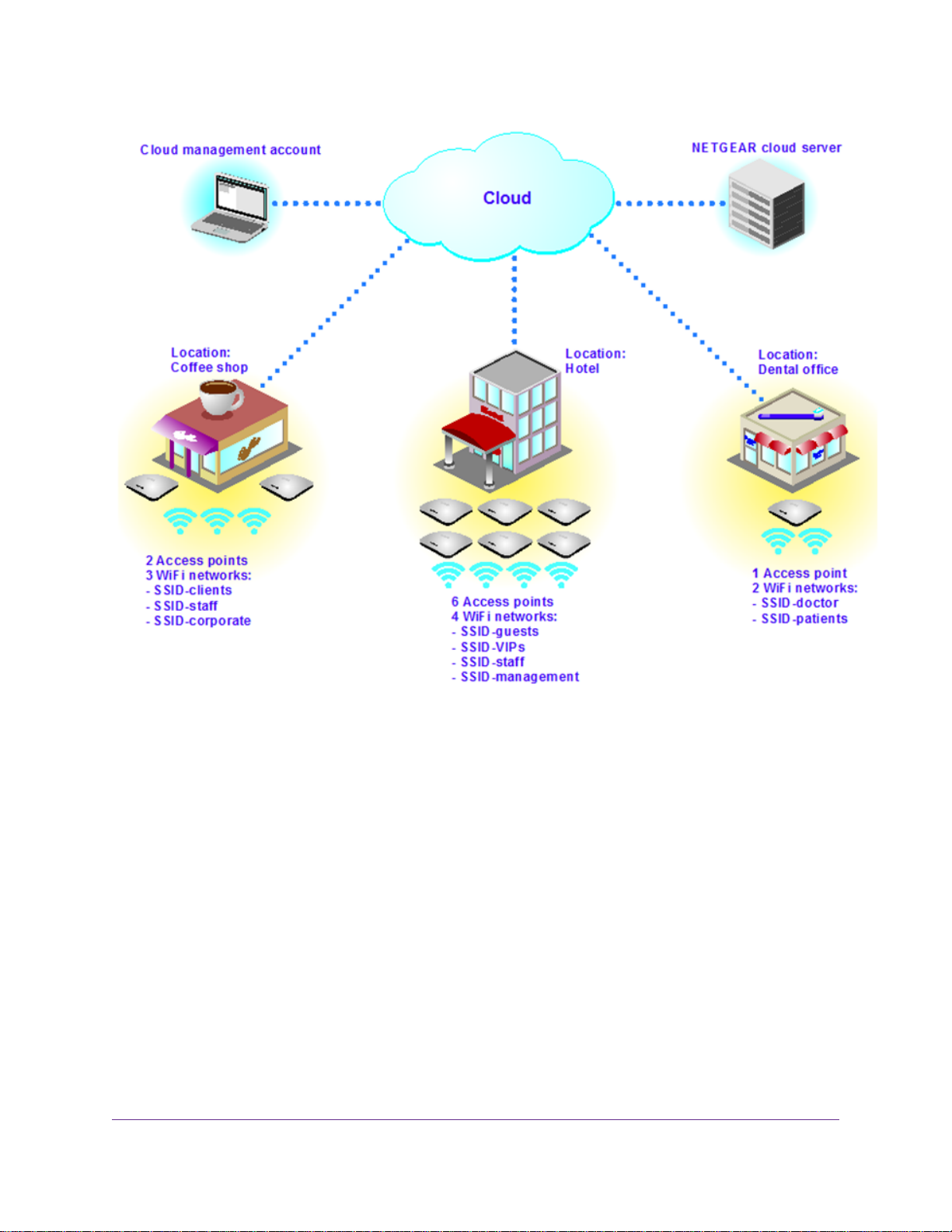
zones.The application integrates Google Maps to display the locations. For each location, you can monitor
its health, usage, and security, as well as its WiFi networks, building, floors, and access points.You can
add a building label and a floor label to an access point that you assign to a location.
The following diagram shows the location-based hierarchy of the application.
Introduction to the Business Central Wireless Manager 2.1
8
Page 9
Business Central Wireless Manager 2.1 Application
Figure 1. Locations with their access points and WiFi networks
Automatic Network Provisioning Concepts
With standalone access points, you add a WiFi network to an access point.With the application, the entire
provisioning process is location based.You add a WiFi network to a location and you add an access point
to the same location.
All networks configured at a location are automatically applied to all access points at that location.Typically ,
a single access point can support eight networks per radio. If an access point supports only a single radio,
the application configures the networks only on that radio.
Optional building and floor labels can help you to organize your access points and you can group access
points together by building and by floor.
Offline provisioning is possible.You can set up locations and WiFi networks while access points are offline.
Then, add access points and assign them to locations, allowing the networks to go online.
Introduction to the Business Central Wireless Manager 2.1
9
Page 10

Business Central Wireless Manager 2.1 Application
Key Functions
The application provides key functions such as provisioning, configuring, managing, and monitoring.
Provisioning Functions
Provisioning lets you add locations, WiFi networks, and access points.Typically, you add a location, set up
a WiFi network at the location, and bring the WiFi networks online by adding access points to the location.
For more information, see Get Started With Cloud Management on page 18.
You could also start by adding access points to a temporary location and decommissioning them just to get
them into inventory. (While decommissioned, access points do not use license credits.) Then, add locations ,
add WiFi networks to the locations, and bring the WiFi networks online by assigning the access points to
the locations. F or information about managing the inventory, see Manage the Device Inventory on page 77.
Configuring and Managing Functions
You can configure and manage features for each location, each WiFi network, and each access point.
Location Functions
For each location, you can configure and manage multiple features. For detailed configuration procedures,
see Manage Locations on page 26, except where otherwise indicated in the following list.
You can configure and manage the following features:
• Add WiFi networks to the location.
For detailed configuration procedures, see Manage WiFi Networks on page 47.
• Add access points to the location.
For detailed configuration procedures, see Manage Devices and Device Inventory on page 68.
• Configure and manage global WiFi, access point, and security settings for the location, including the
following components:
- Automatic radio resource management (Auto RRM) for access point radios
- Management of access point radios, including the WiFi mode, channel frequency, output power,
channel bandwidth, Wi-Fi Multimedia (WMM) settings, maximum number of clients, and antenna
settings
- Radio broadcast on/off schedule
- Access point credentials (that is, setting a global password for accessing the web management
interfaces of cloud-managed access points)
- Firmware management for access points
Introduction to the Business Central Wireless Manager 2.1
10
Page 11

Business Central Wireless Manager 2.1 Application
WiFi Network Functions
For each WiFi network that you set up at a location, you can configure and manage multiple features. For
detailed configuration procedures, see Manage WiFi Networks on page 47.
You can configure and manage the following features:
• Set the security, including broadcast of the network name (SSID) and client separation for the WiFi
network.
• Specify the tagged VLAN for the WiFi network.
• Select the radio (for dual-band access points) for the WiFi network.
• Manage the authentication and encryption for the WiFi network.
• Create a captive portal for free or paid-for access to the WiFi network.
• Set upload and download bandwidth caps for the WiFi network.
• Enable fast roaming for the WiFi network.
• Enable client isolation for the WiFi network.
• Set a radio broadcast on/off schedule for the WiFi network.
Access Point Functions
For each access point that you assign to a location, you can configure and manage multiple features.You
can also decommission the access point from its current location and deploy it to a different location. For
detailed configuration procedures, see Manage Devices and Device Inventory on page 68.
You can configure and manage the following features:
• Assign a name, building, and floor label to the access point.
• Manage the IP address settings for the access point, including the DHCP and DNS server settings.
• Configure the management VLAN (by default, VLAN 1) for the access point.
• Manage the radio settings for the access point, including the WiFi mode, channel frequency, output
power , channel bandwidth, Wi-Fi Multimedia (WMM) settings , maximum number of clients, and antenna
settings.
Monitoring Functions
Monitoring lets you display WiFi network and access point health;WiFi network and access point usage;
WiFi network location maps; alarms and alarm trends; and statistics for networks, access points, traffic,
clients, and neighboring access points. For detailed configuration procedures, see Monitor Your Locations,
Networks, and Devices on page 102.
Account Management Functions
Account management lets you assign locations to license accounts, manage licenses, and in vite application
users (referred to as collaborators). For detailed configuration procedures, see Manage Accounts and
Licenses on page 86.
Introduction to the Business Central Wireless Manager 2.1
11
Page 12

Business Central Wireless Manager 2.1 Application
Application Roles
The application supports the following roles for users who can log in to the application.These users are
different from WiFi users and hotspot users who can connect to a network that is part of the cloud but who
cannot log in to the application.
• Owner. A user who subscribed to the application and owns all license accounts that are set up under
his or her application subscription. An owner can perform any action, including inviting collaborators
(managers, customers, and clerks).
• Manager. A user who can perf orm most administrative functions. A manager (also ref erred to as a cloud
network administrator) is authorized to perform many application functions for license accounts that he
or she does not own.
Although a manager can set up his or her own new license account (and therefore become owner of
that account), a manager can also access other license accounts (that is, accounts that were set up by
other users) and can invite collaborators for other license accounts. However, a manager cannot add
or remove a location from another license account, decommission or remove devices from a location
for another license account, or entirely remove another license account.
• Customer. A user with read-only access to the license account to which he or she w as invited, including
all locations, WiFi networks, and access points that are assigned to that license account. Although a
customer can set up his or her own license account (and therefore become owner of that account), a
customer cannot access other license accounts to which he or she was not invited and cannot invite
collaborators for other license accounts.
• Clerk. A user who can only sell, print, and email vouchers and monitor their use for paid-for captive
portal access for the license account to which he or she was invited. A clerk is also referred to as a
voucher clerk or hotspot clerk. As with other users, a clerk can set up his or her own license account
(and therefore become owner of that account).
Owners, managers, customers, and clerks are referred to as collaborators.
Plan a Location With WiFi Networks and Hotspots
Before you set up a location with one or more large WiFi networks, plan accordingly and perform a site
survey so that you can determine how many access points the location requires. Plan the types of network
authentication and data encryption for WiFi access, the nature of hotspots , whether y ou need usage plans,
and which user groups you must set up.
The following sections describe planning concepts:
• Determine the Location Requirements on page 13
• Determine the Management VLAN on page 13
• Plan the Client Authentication and Data Encryption on page 13
• Plan the Hotspots With Free Access and Paid-For Access on page 14
• Other Planning Considerations on page 14
Introduction to the Business Central Wireless Manager 2.1
12
Page 13

Business Central Wireless Manager 2.1 Application
Determine the Location Requirements
For each location, before y ou set up the location, configure the WiFi netw orks, and assign the access points,
determine its requirements:
• Number of users that must be able to receive WiFi service over managed networks
• Type of security and encryption for the managed networks
• Number of users that must be able to receive WiFi service over a WiFi network or hotspot
• Type of security, encryption, and access for the WiFi network or hotspot
• Number of access points required to provide seamless coverage for all WiFi networks and hotspots
through all buildings and floors of the location
• Number of licenses required to cover all access points at the location
• 802.11 frequency bands and channels that are optimal for WiFi usage
For each large location that you plan to set up, we recommend that you perform a site survey:
• To determine the current RF behavior and detect both 802.11 and non-802.11 noise, run a spectrum
analysis of the channels of the site.
• To determine the maximum throughput that is achievable on clients, run a test to check connectivity
between access points and clients.
• Identify potential RF obstructions and interference sources.
• Determine areas where denser coverage might be required because of heavier usage.
Determine the Management VLAN
To enable all access points at a location to connect over the Internet to the cloud, make sure that the
management VLAN is set up correctly at the location and that all access points at the location use the correct
management VLAN.The default management VLAN ID is ID 1. However, you can change the management
VLAN for individual access points. F or more inf ormation, see Change the Management VLAN for an Access
Point on page 74.
Plan the Client Authentication and Data Encryption
A WiFi user must authenticate to the WiFi network to be able to access WiFi resources. A WiFi network can
support several types of security methods, including those methods that require a RADIUS authentication
server.The encryption option that is available depends on the authentication method that you selected.The
following table lists the authentication and corresponding encryption methods that you configure through
the application.
Introduction to the Business Central Wireless Manager 2.1
13
Page 14

Business Central Wireless Manager 2.1 Application
Table 1. Authentication and encryption options
Authentication
Method
WPA Personal
WPA Enterprise
Type of
Authentication
Network key
(passphrase)
Shared secret
(passphrase)
Encryption
Options
TKIP+AES
TKIP+AES
Authentication
Server
NoneNoneNoneOpen
NoneTKIP or
RADIUS serverTKIP or
Plan the Hotspots With Free Access and Paid-For Access
A captive portal blocks clients from accessing a WiFi network until they are verified. Such a WiFi network
is often referred to as a hotspot.
Plan the hotspots that you want to offer at a location.The type of hotspots that the application supports are
hotspots that offer free access and hotpots that offer paid-for access with a voucher.
The application supports the following authentication methods for hotspots:
• Click-through. No authentication and no email address are required to click through to a hotspot.
• Click-through with custom fields. No authentication is required but other information can be required
to click through to a hotspot.You can specify up to six fields to customize the required information,
which can include a name, email address, mobile phone number, and so on.
• Voucher. A voucher number is required to sign in to a paid-for hotspot.
Although it is a less common approach, you could also use the voucher option to
Note
generate passwords for guest use in an office environment.
For more information, see Add a Captive Portal for Free or Paid-For Access to a WiFi Network on page 52.
Other Planning Considerations
The application functions with the following concepts:
• A WiFi network broadcasts in an entire location, not in an individual building or on a floor only.
• An access point might be configured with a label for a floor in a building at a location b ut carries all WiFi
networks that broadcast at that location.
• All access points at a location function with the same WiFi and radio settings for that location (see
Manage WiFi Networks on page 47 and Manage the Radio and Antenna Settings for a Location on
page 33).
If you disable the broadcast of a WiFi network, the WiFi network stops broadcasting at the entire location.
That is, you cannot stop a WiFi network from broadcasting in a particular building only or on a particular
floor only . It’s either on or off for the entire location. However, you can circumvent these limitations by setting
up more than one location.
Introduction to the Business Central Wireless Manager 2.1
14
Page 15

Business Central Wireless Manager 2.1 Application
Consider the following example:
In a single building (for example, a high-rise, multifloor tower) you want to use the application to manage
the WiFi networks and hotspots through the cloud.The configuration of companies in the building varies:
Some companies occupy an entire floor , some companies share a floor , and some companies occup y more
than one floor. Each floor requires at least one access point and each company requires at least one WiFi
network, but some floors require more access points and some companies require more WiFi networks. All
companies are connected to the Internet through the same high-speed broadband WAN connection.The
following three scenarios cover configuration options for the building:
• For a single company that occupies a single floor, you can do the following:
1. Set up one location for the company.
2. Add all access points that the company requires to the location.
3. Add all WiFi networks that the company requires to the location.
If one or more simultaneous dual-band access points are assigned to the location, you can set up
a maximum of 16 WiFi networks for the location.
• For a single company that occupies several floors, you can do the following:
1. Set up one location for the company.
2. Add all access points that the company requires to the location.
If the company is spread out over floors that are not adjacent, you must set up at least one access
point per floor.
3. Add floor labels to the access points.
Each floor label can represent the floor on which access points are located. Floor labels allow you
to organize the access points by floors.
4. Add all WiFi networks that the company requires to the location.
If the company is spread out over floors that are not adjacent, you must set up at least one WiFi
network per floor.
If one or more simultaneous dual-band access points are assigned to the location, you can set up
a maximum of 16 WiFi networks for the location.
• For different companies that share a single floor, you can do the following:
1. Set up one location for the floor.
2. Add a sufficient number of access points to the location so that the WiFi requirements for all
companies on the floor are covered.
3. For each company on the floor, add one or more WiFi networks to the location.
If one or more simultaneous dual-band access points are assigned to the location, you can set up
a maximum of 16 WiFi networks for the location.
Introduction to the Business Central Wireless Manager 2.1
15
Page 16

Business Central Wireless Manager 2.1 Application
Compatible NETGEAR WiFi Access Points
Before the application can manage an access point, the access point must run the required firmware version
that is cloud enabled.This release supports the following NETGEAR WiFi access points running cloud-enabled
firmware:
• WAC730 ProSAFE 3x3 Dual-Band Wireless AC Access Point
• WAC720 ProSAFE 2x2 Dual-Band Wireless AC Access Point
• WNDAP660 ProSAFE Dual-Band Wireless-N Access Point
• WNDAP360 ProSAFE Dual-Band Wireless-N Access Point
• WNDAP350 ProSAFE Dual-Band Wireless-N Access Point
• WNAP320 ProSAFE Wireless-N Access Point
• WNAP210v2 ProSAFE Wireless-N Access Point
The following table lists the minimum required standalone firmware version that an access point must run
for you to be able to upgrade the access point to the required cloud-enabled firmware version.
Table 2. Firmware requirements for upgrade to the cloud-enabled firmware version
Access Point Model
Minimum Required Standalone
Firmware for Upgrade to
Cloud-Enabled Firmware
If your access point runs a standalone firmware version that is earlier than the minimum required standalone
firmware version, you first must upgrade the access point to the minimum required standalone firmware
version before you can upgrade the access point to the required cloud-enabled firmware version.
CAUTION:
If you do not first upgrade to the minimum required standalone firmware version but
attempt to upgrade directly to the required cloud-enabled firmware version, y ou might be
locked out of the access point. In that situation, you must log in to the access point over
an SSH connection with the user name admin and the password that is configured for
the access point and issue the restore-factory-default command to reset the
access point to factory default settings.
Required
Cloud-Enabled
Firmware
v3.5.6.0 or laterv3.1.1.0 or a later standalone versionWAC730 ProSAFE 3x3 Dual-Band Wireless AC Access Point
v3.5.6.0 or laterv3.1.1.0 or a later standalone versionWAC720 ProSAFE 2x2 Dual-Band Wireless AC Access Point
v3.5.5.0 or laterv2.0.5 or a later standalone versionWNDAP660 ProSAFE Dual Band Wireless-N Access Point
v3.5.5.0 or laterv2.1.12 or a later standalone versionWNDAP360 ProSAFE Dual Band Wireless-N Access Point
v3.5.5.0 or laterv2.1.9 or a later standalone versionWNDAP350 ProSAFE Dual Band Wireless-N Access Point
v3.5.5.0 or laterv2.1.6 or a later standalone versionWNAP320 ProSAFE Wireless-N Access Point
v3.5.5.0 or laterv2.1.5 or a later standalone versionWNAP210v2 ProSAFE Wireless-N Access Point
If your access point runs the minimum required standalone firmware version, you must load the required
cloud-enabled firmware version onto the access point. Using the web management interface of the access
Introduction to the Business Central Wireless Manager 2.1
16
Page 17

Business Central Wireless Manager 2.1 Application
point, upgrade the access point to the cloud-enabled firmware version, and reset the access point to f actory
default settings. For more information about preparing your access points for cloud management, see the
NETGEAR Business Central Wireless Manager How to Start Guide, which you can download from
downloadcenter.netgear.com.
Once you perform the one-time cloud-enabled firmware upgrade for the access point, the application can
centrally manage future firmware upgrades for the cloud-managed access point.
For more information about cloud-managed access points, see Manage De vices and
Note
Device Inventory on page 68.
Definitions of Access Point Terms
This manual uses the following definitions of access point terms:
• Cloud-managed access point. A NETGEAR access point that is installed at a location and is controlled
by the application.
• Neighbor access point. An access point that is within the radio range of and discovered by a
cloud-managed access point.The access point can be another cloud managed access point or an
access point that is not cloud managed.The access point can be known, unknown, or rogue.
• Rogue access point. An access point that is broadcasting an SSID that is identical to the SSID of a
cloud-managed access point.This type of rogue access point is also referred to as an evil twin. Howe ver ,
a cloud-managed access point can be rogue if it is deployed at another location or belongs to another
user.
• Known AP. Either a NETGEAR access point that is cloud managed and that the application automatically
classified as a known access point or another access point that is not cloud managed and that you or
a collaborator classified as a known access point.
• Unknown AP. An unknown access point that is within the radio range of and discovered by a cloud
managed access point and that you or a collaborator could mark as a known access point. A
cloud-managed access point can be unknown if it is deployed at another location or belongs to another
user.
Introduction to the Business Central Wireless Manager 2.1
17
Page 18

Get Started With Cloud Management
Before you can manage WiFi networks in the cloud, you must set up a least one location, add one or more WiFi
networks to the location, and add one or more access points to the location.
This chapter includes the following sections:
• Add Your First Location on page 19
• Add a First WiFi Network to a Location on page 20
• Add a First Access Point to a Location on page 23
For information about preparing your access points and subscribing to the BCWM application,
Note
see the NETGEAR Business Central Wireless Manager How to Start Guide, which you can
download from downloadcenter.netgear.com.
2
18
Page 19

Business Central Wireless Manager 2.1 Application
Add Your First Location
Before you can add WiFi networks and access points, you must set up at least one location. For access
points (and therefore WiFi networks) to become active, you must assign the location to a license account.
To add your first location and assign it to a license account:
1. Open a browser on your computer.
2. In the address bar, enter https://bc.netgear.com.
The application login page displays.
3. Enter the email address and password for your BCWM and click the Login button.
The Monitoring page displays.
4. Select Configuration.
The Configuration page displays and does not yet show any locations.
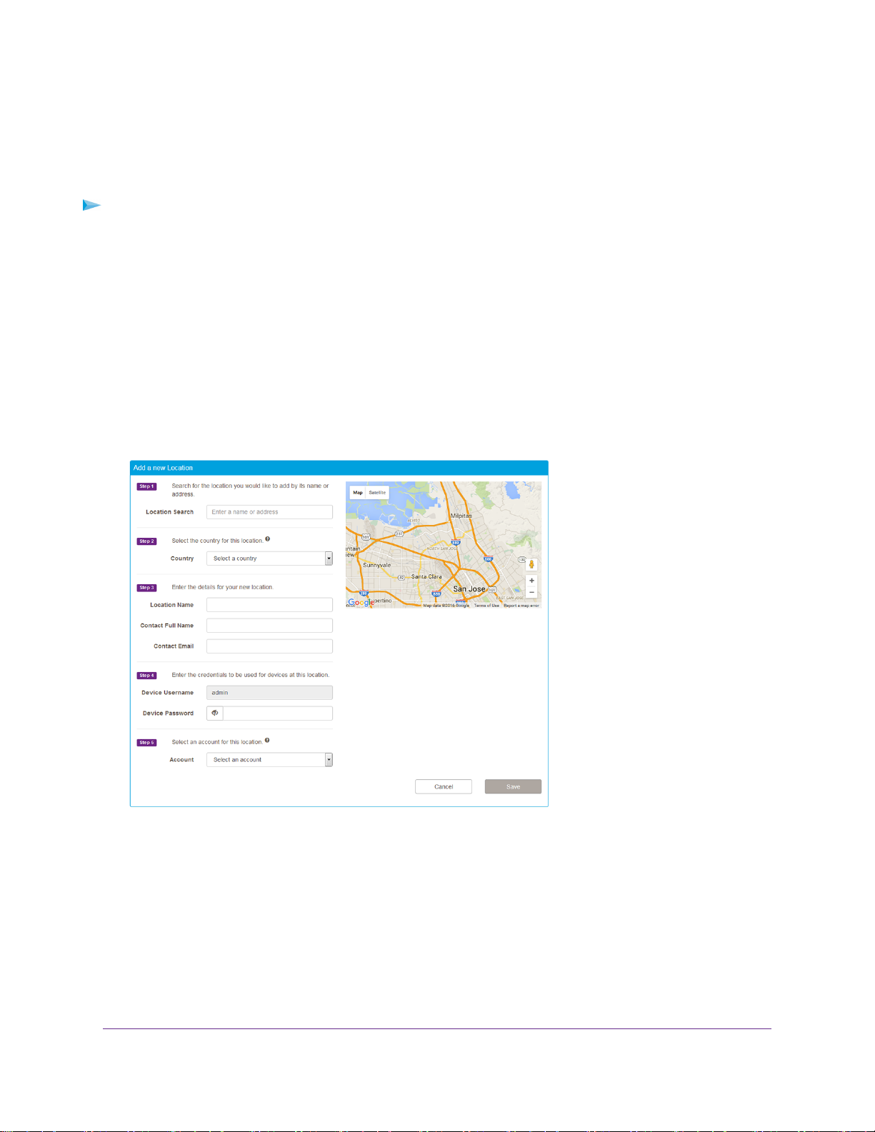
5. Click the + New Location button.
6. In the Location Search field, enter a name or address and select the location that Google search
generates.
The location displays on the map.
7. Make sure that the correct country is selected from the Country menu.
When you complete the Location Search field, the country is automatically selected from the Country
menu.
The selection from the Country menu determines the radio settings for access points at the location.
Once the location is created, you cannot change the country selection.
Get Started With Cloud Management
19
Page 20
Business Central Wireless Manager 2.1 Application
8. Enter the location name, contact name, and contact email address that you want to be associated with
the location.
9. In the Device Password field, enter the password for accessing the web management interf ace of any
cloud-managed access point that is assigned to the location.
Click the eye icon to make the password visible.
This password is pushed to all access points that you assign to the location.
The Device Username field shows the fixed user name (admin) for accessing the
Note
web management interface of any cloud-managed access point that is assigned to
the location.You cannot change this name.
10. From the Account menu, select the account to which the location must be assigned.
An account is a set of locations that are funded by the same license. Each location must be assigned
to an account with an active license (which can be a trial license) for access points to be licensed and
active.The Accounts menu lists the available license accounts. If you did not create a license account,
only the default license account is available from the menu.
11. Click the Save button.
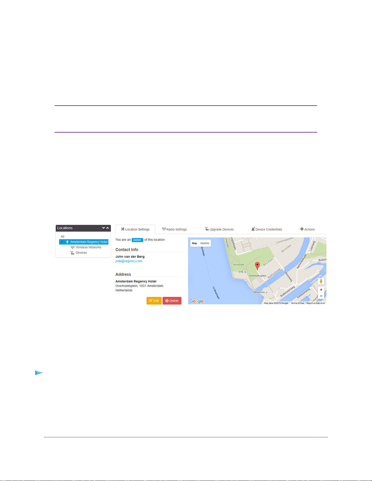
Your settings are saved.The location displays in the Locations tree on the left. Below the location in
the tree, the Wireless Networks and Devices headings display.
Add a First WiFi Network to a Location
When you add a location (see Add Your First Location on page 19), the application automatically adds a
WiFi Networks heading for the location in the Locations tree on the Configuration page , but you m ust define
one or more WiFi networks that can broadcast at the location.
To add a first WiFi network to a location:
1. Open a browser on your computer.
2. In the address bar, enter https://bc.netgear.com.
The application login page displays.
3. Enter the email address and password for your BCWM and click the Login button.
The Monitoring page displays.
Get Started With Cloud Management
20
Page 21
Business Central Wireless Manager 2.1 Application
4. Select Configuration.
The Configuration page displays and shows the location that you added (see Add Your First Location
on page 19).
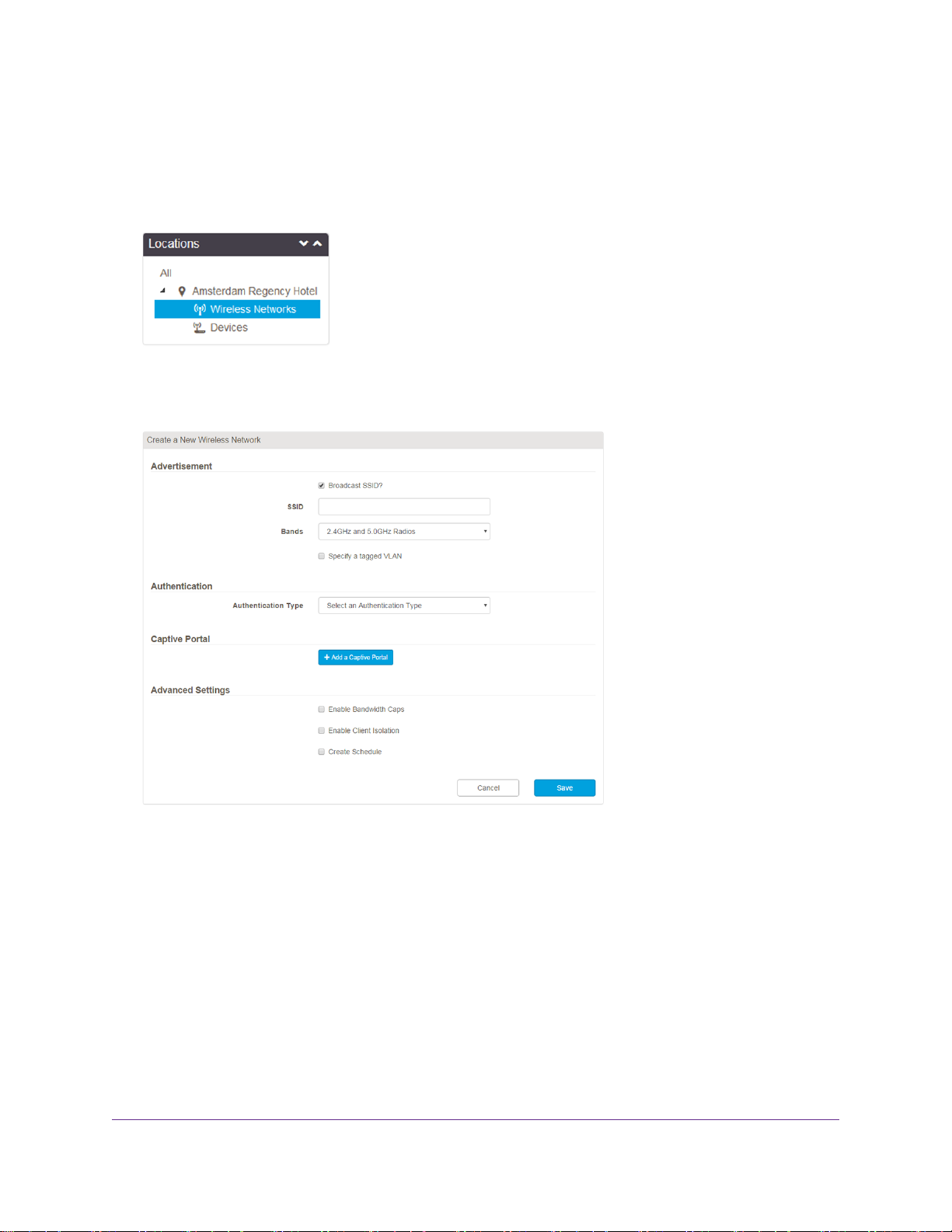
5. In the Locations tree, click Wireless Networks.
The page displays the following message: There are no wireless networks configured for this location.
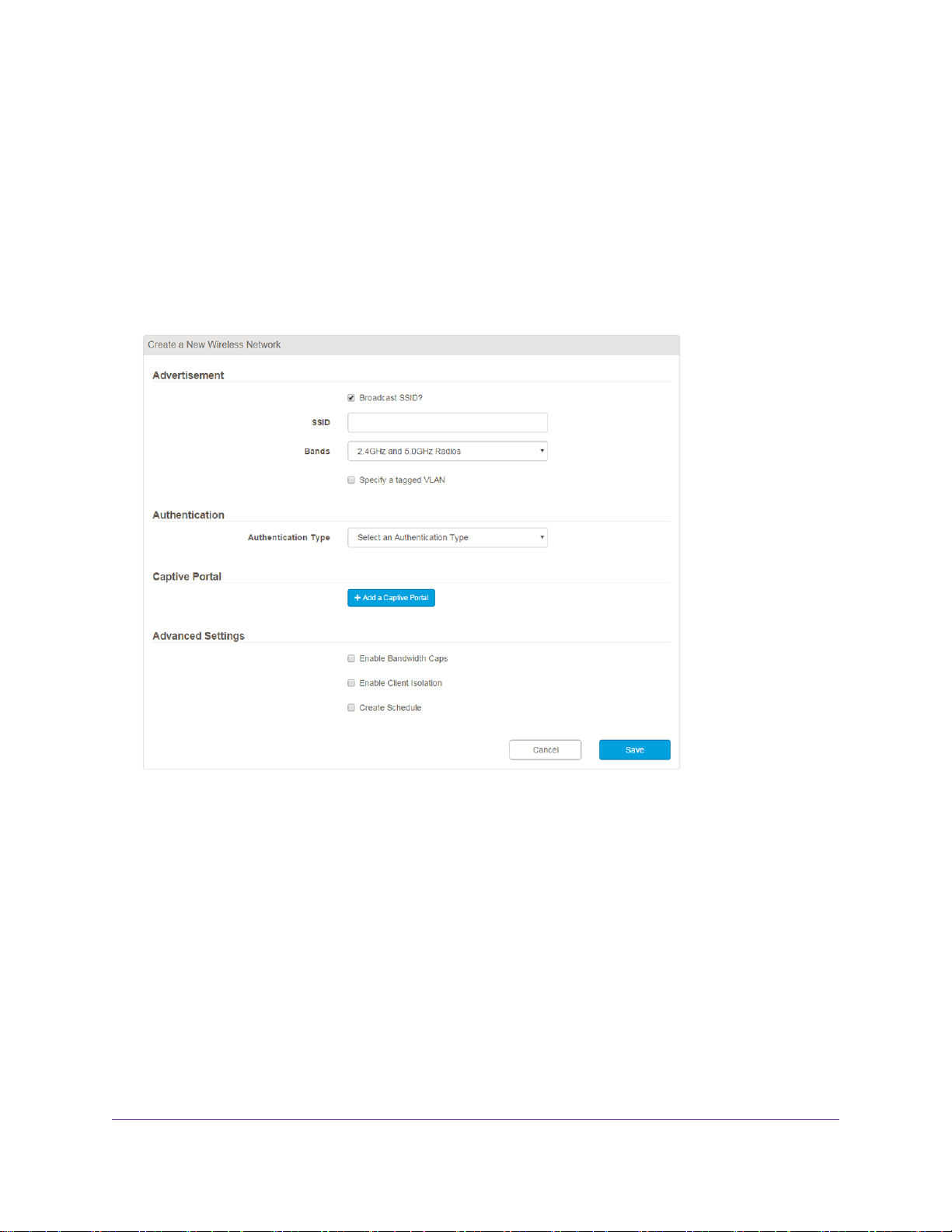
6. Click the + New Wireless Network button.
7. In the SSID field, enter a WiFi network name (SSID).
You can use up to and including 32 ASCII printable (typeable) characters. Do not use extended ASCII
characters, control ASCII characters, or ASCII characters that you compose with the Alt key on your
keyboard.
By default, the application broadcasts the SSID. If you want to hide the SSID so that only users who
know the SSID can access it, clear the Broadcast SSID check box.
8. From the Bands menu, select the WiFi band or bands.
The default setting is 2.4GHz and 5.0GHz Radios, which applies to dual-band access points only. If
an access points supports a single band only, the access points broadcasts on that band, unless your
selection from the Bands menu disables that band.
9. To specify a tagged VLAN, select the Specify a tagged VLAN check box, and in the VLAN ID field,
enter the VLAN ID.
Get Started With Cloud Management
21
Page 22

Business Central Wireless Manager 2.1 Application
The VLAN ID is a 12-bit number that identifies the tagged VLAN. If the connection from the access
points to the Internet gateway requires an IEEE 802.1Q VLAN tag, you must specify a VLAN ID. If
multiple WiFi networks operate over the same physical Ethernet link, VLANs can provide isolation and
separation.
10. From the Authentication Type menu, select the type of authentication:
• Open.You do not need to specify any additional information because the network functions without
authentication and encryption.
• WPA Personal. In the Password field, you must specify the password that is required to access
the network.You can enter up to 63 alphanumeric and special characters.
The default encryption method is TKIP+AES, but you can select the Change Data Encryption
check box and, from the Data Encryption menu, select TKIP.
• WPA Enterprise.You must specify a RADIUS profile and the network must be connected to a
RADIUS server.
For more information, see Change the Authentication and Encryption for a WiFi Network on page
49.
11. To assign a captive portal to the WiFi network, click the +Add a Captive Portal button.
For information about configuring a captive portal, see Add a Captive Portal for Free Access to a WiFi
Network on page 53.
12. To specify bandwidth caps, select the Enable Bandwidth Caps check box and adjust the upload and
download bandwidth caps.
By default, the upload and download bandwidth caps are 1000 Kbps each. For each type of bandwidth
cap, the minimum value is 64 Kbps and the maximum value is 10 Gbps.
13. If you select WPA Personal (with TKIP + AES) or WPA Enterprise from the Authentication Type
menu, you can configure fast roaming (802.11r) for the WAC720 and WAC730 access points by doing
the following:
a. Select the Enable Fast Roaming check box.
For more information about fast roaming and associated restrictions, see Enable Fast Roaming for
a WiFi Network on page 63.
If you select the Enable Fast Roaming chec k bo x, the Exchange F ast Roaming Info Over Wired
Network check box displays.
b. To enable fast roaming information to be exchanged over the wired network, select the Exchange
Fast Roaming Info Over Wired Network check box.
If you enable f ast roaming, b y def ault, f ast roaming information is exchanged ov er the WiFi network
instead of the wired network.
14. To enable client isolation, select the Enable Client Isolation check box.
Enabling client isolation on a WiFi netw ork for a location with 802.11ac access points
Note
enables client isolation for all WiFi networks for those access points.
15. To set up a radio on/off broadcast schedule, select the Create Schedule check box.
Get Started With Cloud Management
22
Page 23
Business Central Wireless Manager 2.1 Application
For information about configuring a radio on/off broadcast schedule, see Set Up or Change a Radio
On/Off Broadcast Schedule for a WiFi Network on page 65.
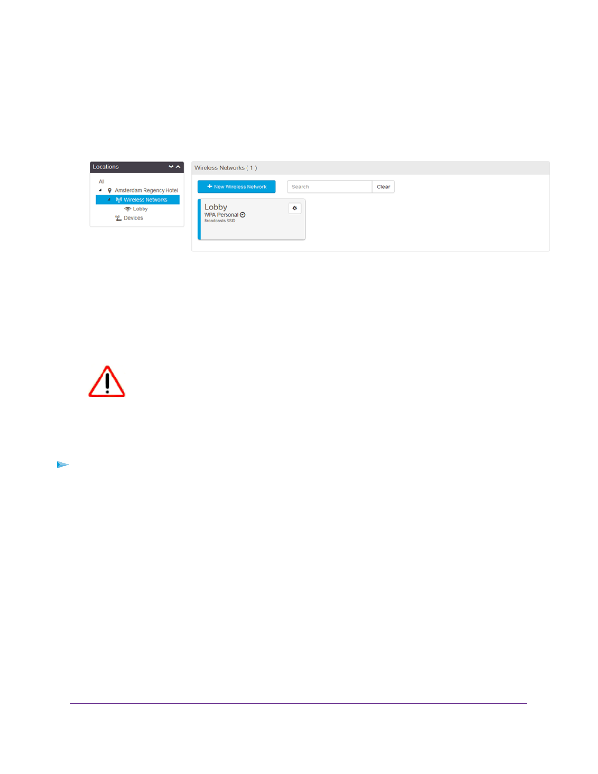
16. Click the Save button.
Your settings are saved. In the Locations tree on the left, the WiFi network displays under the Wireless
Networks heading for the location.
Add a First Access Point to a Location
When you add a location (see Add Your First Location on page 19), the application automatically adds a
Devices heading for the location in the Locations tree on the Configuration page , b ut y ou must add at least
one access point that can carry the WiFi networks that you configure at the location.
CAUTION:
If you add an access point to a location but do not add a WiFi network to the location,
the access point continues to broadcast its default SSIDs and provides open networks
without any security. Make sure that you add a WiFi network to the location (see Add
a First WiFi Network to a Location on page 20) so that you can control WiFi security.
To add a first access point to a location:
1. Open a browser on your computer.
2. In the address bar, enter https://bc.netgear.com.
The application login page displays.
3. Enter the email address and password for your BCWM and click the Login button.
The Monitoring page displays.
4. Select Configuration.
The Configuration page displays and shows the location that you added (see Add Your First Location
on page 19).
Get Started With Cloud Management
23
Page 24
Business Central Wireless Manager 2.1 Application
5. In the Locations tree, click Devices.
The page displays the following message: There are no devices configured for this location.
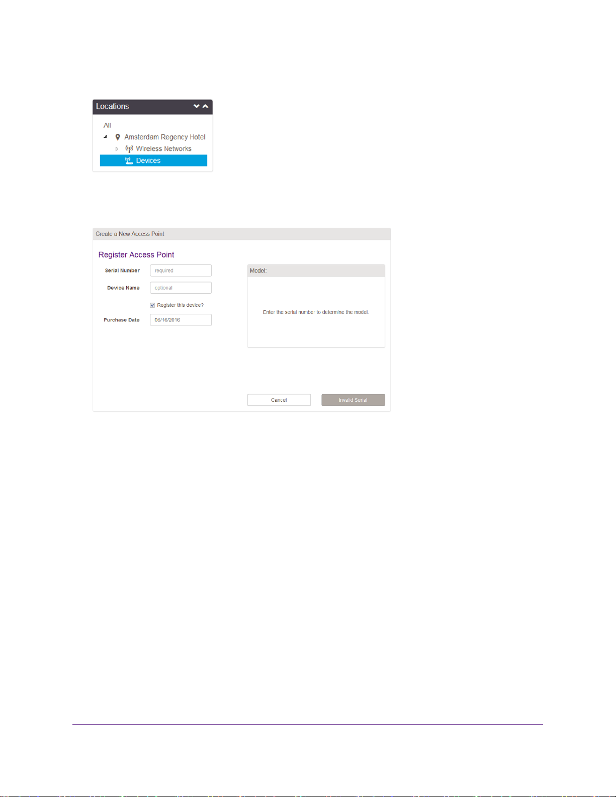
6. Click the + New Device button.
7. In the Serial Number field, enter the precise serial number for the access point.
If you do not enter a correct serial number, you cannot add the access point to the network. After you
enter a correct serial number, an image of the associated model displays in the Model field, and the
gray Invalid Serial button changes into the Save button.
8. In the Device Name field, enter a name for the access point.
The name does not need to be the factory default name.
9. To register the access point with NETGEAR, keep the Register this device check box selected and
enter your date of purchase in the Purchase Date field.
By default, the Register this device check box is selected. If you do not need or want to register the
access point, clear the check box.
10. Click the Save button.
Your settings are saved. In the Locations tree on the left, the access point displays under the Devices
heading for the location.
Get Started With Cloud Management
24
Page 25

Business Central Wireless Manager 2.1 Application
Note the following about access point states:
• If the access point is not connected to the Internet, the application displays the status Waiting.
• If the location to which you added the access point is assigned to an unlicensed account, the access point
displays the status Unlicensed and does not become active until y ou add a license to the account (see Add
a License to an Account on page 90).
CAUTION:
If an access point remains unlicensed and is not active, it broadcasts its default
SSIDs and provides open networks without any security. Make sure that the
account to which you assigned the location is licensed so that the access point
becomes active.
• If the access point is connected to the Internet and connects to the application for the first time, it might take
between 5 and 10 minutes before the access point is connected and the application displays the status
Online. During this period, the application might need to push the latest firmware to the access point,
automatically reboot the access point, push the configuration to the access point, and automatically reboot
the access point again.
The following figure shows the status Online.
Get Started With Cloud Management
25
Page 26

Manage Locations
Locations form the key building b locks of y our cloud network.Y ou can set up new and manage e xisting locations,
add WiFi networks and access points to a location, manage radio settings for a location, and manage firmware
and device credentials for all access points assigned to a location.
This chapter includes the following sections:
• Add a Location on page 27
• Add a WiFi Network to a Location on page 28
• Add an Access Point to a Location on page 31
• Change the Basic Settings for a Location on page 33
• Manage the Radio and Antenna Settings for a Location on page 33
• Run or Schedule Automatic Radio Frequency Management for a Location on page 36
• Manage Load Balancing for a Location on page 38
• Upgrade Firmware on Devices at a Location on page 40
• Reboot a Location on page 44
3
• Change the Device Credentials for a Location on page 45
• Remove a Location on page 46
For information about moving a location from one account to another account, see Remov e
Note
a Location From an Account on page 94 and Add a Location to an Account on page 93.
26
Page 27
Business Central Wireless Manager 2.1 Application
Add a Location
A location is a physical address where WiFi netw orks and access points are installed.You can add multiple
locations, for example, for branches and remote offices.
To add a location and assign it to a license account.
1. Open a browser on your computer.
2. In the address bar, enter https://bc.netgear.com.
The application login page displays.
3. Enter the email address and password for your BCWM and click the Login button.
The Monitoring page displays.
4. Select Configuration.
The Configuration page displays any existing locations.
5. Click the + New Location button.
6. In the Location Search field, enter a name or address and select the location that Google search
generates.
The location displays on the map.
7. Make sure that the correct country is selected from the Country menu.
When you complete the Location Search field, the country is automatically selected from the Country
menu.
The selection from the Country menu determines the radio settings for access points at the location.
Once the location is created, you cannot change the country selection.
Manage Locations
27
Page 28
Business Central Wireless Manager 2.1 Application
8. Enter the location name, contact name, and contact email address that you want to be associated with
the location.
9. In the Device Password field, enter the password for accessing the web management interf ace of any
cloud-managed access point that is assigned to the location.
Click the eye icon to make the password visible.
This password is pushed to all access points that you assign to the location.
The Device Username field shows the fixed user name (admin) for accessing the
Note
web management interface of any cloud-managed access point that is assigned to
the location.You cannot change this name.
10. From the Account menu, select the account to which the location must be assigned.
An account is a set of locations that are funded by the same license. Each location must be assigned
to an account with an active license (which can be a trial license) for access points to be licensed and
active.The Accounts menu lists the available license accounts. If you did not create a license account,
only the default license account is available from the menu.
11. Click the Save button.
Your settings are saved.The location displays in the Locations tree on the left. Below the location in
the tree, the Wireless Networks and Devices headings display.
Add a WiFi Network to a Location
You can add a WiFi network to a location.The WiFi network becomes active only after you add one or more
access points to the location, the location is added to a license account, and the access points are in the
active connected state.
To add a WiFi network to a location:
1. Open a browser on your computer.
2. In the address bar, enter https://bc.netgear.com.
The application login page displays.
Manage Locations
28
Page 29
Business Central Wireless Manager 2.1 Application
3. Enter the email address and password for your BCWM and click the Login button.
The Monitoring page displays.
4. Select Configuration.
The Configuration page displays any existing locations.
5. In the Locations tree, click the location.
The Configuration page displays the settings for the selected location.
6. From the Actions menu, select + Add Wireless Network.
7. In the SSID field, enter a WiFi network name (SSID).
By default, the application broadcasts the SSID. If you want to hide the SSID so that only users who
know the SSID can access it, clear the Broadcast SSID check box.
8. From the Bands menu, select the WiFi band or bands.
The options are 2.4GHz and 5.0GHz Radios, 2.4GHz Radio only, and 5.0GHz Radio only.The default
setting is 2.4GHz and 5.0GHz Radios, which applies to dual-band access points only. If an access
points supports a single band only, the access points broadcasts on that band, unless your selection
from the Bands menu disables that band.
9. To specify a tagged VLAN, select the Specify a tagged VLAN check box, and in the VLAN ID field,
enter the VLAN ID.
The VLAN ID is a 12-bit number that identifies the tagged VLAN. If the connection from the access
points to the Internet gateway requires an IEEE 802.1Q VLAN tag, you must specify a VLAN ID. If
multiple WiFi networks operate over the same physical Ethernet link, VLANs can provide isolation and
separation.
Manage Locations
29
Page 30

Business Central Wireless Manager 2.1 Application
10. From the Authentication Type menu, select the type of authentication:
• Open.You do not need to specify any additional information because the network functions without
authentication and encryption.
• WPA Personal. In the Password field, you must specify the password that is required to access
the network.You can enter up to 63 alphanumeric and special characters.
The default encryption method is TKIP+AES, but you can select the Change Data Encryption
check box and, from the Data Encryption menu, select TKIP.
• WPA Enterprise.You must specify a RADIUS profile and the network must be connected to a
RADIUS server.
For more information about WPA Enterprise, see Change the Authentication and Encryption for a
WiFi Network on page 49.
11. To assign a captive portal to the WiFi network, click the +Add a Captive Portal button.
For information about configuring a captive portal, see Add a Captive Portal for Free Access to a WiFi
Network on page 53.
12. To specify bandwidth caps, select the Enable Bandwidth Caps check box and adjust the upload and
download bandwidth caps.
By default, the upload and download bandwidth caps are 1000 Kbps each. For each type of bandwidth
cap, the minimum value is 64 Kbps and the maximum value is 10 Gbps.
13. To enable client isolation, select the Enable Client Isolation check box.
Enabling client isolation on a WiFi netw ork for a location with 802.11ac access points
Note
enables client isolation for all WiFi networks for those access points.
14. If you select WPA Personal (with TKIP + AES) or WPA Enterprise from the Authentication Type
menu, you can configure fast roaming (802.11r) for the WAC720 and WAC730 access points by doing
the following:
a. Select the Enable Fast Roaming check box.
Although you can configure fast roaming regardless of the access points that you are deploying at
a location, fast roaming applies only to the WAC720 and WAC730 access points and to clients that
support fast roaming. If y ou enable fast roaming for a WiFi network that is broadcast on a WAC720
or WAC730 access point only, a client that does not support fast roaming cannot connect to the
WiFi network. In such a situation, you could set up an additional WiFi network without fast roaming
to serve the clients that do not support fast roaming.
If you select the Enable Fast Roaming chec k bo x, the Exchange F ast Roaming Info Over Wired
Network check box displays.
b. To enable fast roaming information to be exchanged over the wired network instead of the WiFi
network, select the Exchange Fast Roaming Info Over Wired Network check box.
The default setting is that fast roaming information is exchanged over the WiFi network instead of
the wired network.
15. To set up a radio on/off broadcast schedule, select the Create Schedule check box.
Manage Locations
30
Page 31

Business Central Wireless Manager 2.1 Application
For information about configuring a radio on/off broadcast schedule, see Set Up or Change a Radio
On/Off Broadcast Schedule for a WiFi Network on page 65.
16. Click the Save button.
Your settings are saved. In the Locations tree on the left, the WiFi network displays under the Wireless
Networks heading for the location.
Add an Access Point to a Location
You can add an access point to location.The location must be assigned to a license account with an active
license (see Add a License to an Account on page 90). Otherwise, the access point that you add remains
in the unlicensed state and does not become active (which means that it broadcasts its default SSIDs and
provides open networks without any security), preventing WiFi networks that you add to the location from
coming up.
CAUTION:
If you add an access point to a location but do not add a WiFi network to the location,
the access point continues to broadcast its default SSIDs and provides open networks
without any security. Make sure that you add a WiFi network to the location (see Add
a WiFi Network to a Location on page 28) so that you can control WiFi security.
To add an access point to a location:
1. Open a browser on your computer.
2. In the address bar, enter https://bc.netgear.com.
The application login page displays.
3. Enter the email address and password for your BCWM and click the Login button.
The Monitoring page displays.
4. Select Configuration.
The Configuration page displays any existing locations.
5. In the Locations tree, click the location.
The Configuration page displays the settings for the selected location.
Manage Locations
31
Page 32

Business Central Wireless Manager 2.1 Application
6. From the Actions menu, select + Add Device.
7. In the Serial Number field, enter the precise serial number for the access point.
If you do not enter a correct serial number, you cannot add the access point to the network. After you
enter a correct serial number, an image of the associated model displays in the Model field, and the
gray Invalid Serial button changes into the Save button.
8. In the Device Name field, enter a name for the access point.
The name does not need to be the factory default name.
9. To register the access point with NETGEAR, keep the Register this device check box selected and
enter your date of purchase in the Purchase Date field.
By default, the Register this device check box is selected. If you do not need or want to register the
access point, clear the check box.
10. Click the Save button.
Your settings are saved. In the Locations tree on the left, the access point displays under the Devices
heading for the location.
Note the following about access point states (see View the Access Point Inventory and Connection Status in
the Application on page 148):
• If the access point is not connected to the Internet, the application displays the status Waiting.
• If the location to which you added the access point is assigned to an unlicensed account, the access point
displays the status Unlicensed and does not become active until y ou add a license to the account (see Add
a License to an Account on page 90).
Manage Locations
32
Page 33

Business Central Wireless Manager 2.1 Application
CAUTION:
If an access point remains unlicensed and is not active, it broadcasts its default
SSIDs and provides open networks without any security. Make sure that the
account to which you assigned the location is licensed so that the access point
becomes active.
• If the access point is connected to the Internet and connects to the application for the first time, it might take
between 5 and 10 minutes before the access point is connected and the application displays the status
Online. During this period, the application might need to push the latest firmware to the access point,
automatically reboot the access point, push the configuration to the access point, and automatically reboot
the access point again.
Change the Basic Settings for a Location
You can change the basic settings for a location.These settings include the location address, location name,
contact name, and contact email, and the access point credentials for the location (the device password).
To change the settings for a location:
1. Open a browser on your computer.
2. In the address bar, enter https://bc.netgear.com.
The application login page displays.
3. Enter the email address and password for your BCWM and click the Login button.
The Monitoring page displays.
4. Select Configuration.
The Configuration page displays any existing locations.
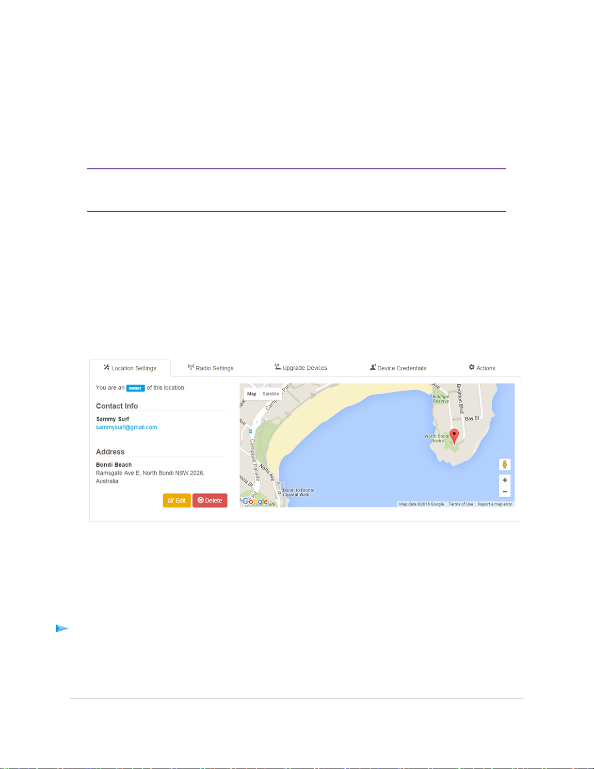
5. In the Locations tree, click the location.
The Configuration page displays the settings for the selected location.
6. Click the orange Edit button.
The page adjusts and the fields become editable.
7. Change the information as needed.
8. Click the Save button.
Your settings are saved.
Manage the Radio and Antenna Settings for a Location
You can manage the radio settings that apply to all access points that are assigned to a location.The default
settings often work well but situations might occur in which you want to change the settings. Managing the
radio settings includes enabling or disabling a radio, changing the WiFi mode, changing the WiFi channel,
changing the WiFi bandwidth, changing the transmission output power, changing the Wi-Fi Multimedia
Manage Locations
33
Page 34

Business Central Wireless Manager 2.1 Application
(WMM) settings, changing the maximum number of supported clients, and specifying the default internal or
optional external antenna.
For information about managing the radio settings f or an individual access point, see
Note
Change the Radio and WiFi Settings for a Device on page 70.
To manage the radio settings for a location:
1. Open a browser on your computer.
2. In the address bar, enter https://bc.netgear.com.
The application login page displays.
3. Enter the email address and password for your BCWM and click the Login button.
The Monitoring page displays.
4. Select Configuration.
The Configuration page displays any existing locations.
5. In the Locations tree, click the location.
The Configuration page displays the settings for the selected location.
6. Click the Radio Settings tab.
The Configuration page displays the common radio settings.
7. Click the Edit Radios button.
For information about using automatic radio frequency (Auto RF) management, see Run or Schedule
Automatic Radio Frequency Management for a Location on page 36.
Manage Locations
34
Page 35

Business Central Wireless Manager 2.1 Application
8. Change the settings:
• Radio. A nonconfigurable field that shows the radio number (WLAN0 or WLAN1) for the access
point.
• Enabled. By default, the radio is enabled.To disable the radio, clear the check box.
• Band. A nonconfigurable field that shows the radio band that is associated with the WiFi mode.
• Mode. From the menu, select the WiFi mode for the radio. By default, the most advanced WiFi
mode is selected.
• Channel.You can select a static channel from the menu.The supported channels depend on the
region of operation for the access point. By default, cloud-managed access points autoconfigure
their channels (that is, the channel setting is Auto).
• Power. By default, the transmission output for an access point is set to maximum power. From the
menu, you can select a lower output po wer for each WiFi band that the access point supports.The
supported output options are Full, Half, Quarter, Eighth, Minimum.
• Bandwidth. From the menu, select the WiFi bandwidth, which is also referred to as the channel
width. A wider channel improves the performance, but some legacy devices can operate only in
either 20 MHz or 40 MHz.The supported WiFi bandwidths depend on the access point model.
• WMM Mode. By default, WMM is enabled, allowing time-dependent WiFi traffic such as video and
audio to receive a higher priority than data WiFi traffic.You can disable WMM.
• WMM Power Save. By default, the WMM Power Save feature is enabled, increasing the efficiency
and flexibility of data transmission and thereby allo wing battery-powered equipment to sa v e po wer.
You can disable the WMM Power Save feature.
• Max Clients. A r adio on a NETGEAR access point can typically support between 64 and 128 clients.
However, allowing the maximum number of clients might not be the most suitable configuration for
a site with a large number of clients.To prevent oversubscription and congestion and to improve
throughput and latency, in the Max Clients column, for each radio, use the up and down arows to
specify the maximum number of allowed clients, or type a n umber in the field. F or more inf ormation,
see Manage Load Balancing for a Location on page 38.
• Antenna. By def ault, the setting is Internal. External antennas are optional accessories. If you select
External, the configuration takes effect only if the access point is configured with one or more
external antennas.
9. Click the Save button.
A pop-up window opens and displays a warning.
10. Click the Save button in the pop-up window.
Your settings are saved. Connected clients lose their connection momentarily while the access points
reprograms their settings.
11. Click the Dismiss button.
The pop-up window closes.
Manage Locations
35
Page 36

Business Central Wireless Manager 2.1 Application
Run or Schedule A utomatic Radio Frequency Management for a Location
You can manage the radio settings that apply to all access points that are assigned to a location by running
automatic radio frequency (Auto RF) management, which is also referred to as automatic radio resource
management (Auto RRM). Auto RF management attempts to configure the optimum radio settings for the
access points.You can either allocate all available channels to participate in Auto RF management or select
specific channels only.You can run Auto RF management immediately or schedule it to run at time when
you expect minimal WiFi traffic. (Running Auto RF management causes connected clients to momentarily
lose connection.)
For information about managing the radio settings f or an individual access point, see
Note
Change the Radio and WiFi Settings for a Device on page 70.
To run or schedule Auto RF management for a location:
1. Open a browser on your computer.
2. In the address bar, enter https://bc.netgear.com.
The application login page displays.
3. Enter the email address and password for your BCWM and click the Login button.
The Monitoring page displays.
4. Select Configuration.
The Configuration page displays any existing locations.
5. In the Locations tree, click the location.
The Configuration page displays the settings for the selected location.
6. Click the Radio Settings tab.
The Configuration page displays the common radio settings.
Manage Locations
36
Page 37

Business Central Wireless Manager 2.1 Application
7. Click the Edit Radios button.
For information about manually changing the radio and WiFi settings for a location, see Change the
Radio and WiFi Settings for a Device on page 70.
8. To allocate the channels that must participate in Auto RF management, do the following:
• To select or clear all available channels, click the All link under 2.4GHz, the All link under 5GHz,
or both. By default, all available channels are selected, so the first time that you click an All link, all
channels in the radio band are cleared.
• To select or clear an individual channel, select or clear the check box that is associated with the
channel.
9. To run Auto RF management immediately, do the following:
a. Click the Auto RF button.
A pop-up window opens and displays a warning.
WARNING:
Clients are disconnected when Auto RF management runs.
b. Click the Save button.
Auto RF management runs and the new settings are saved.
c. Click the Dismiss button.
Manage Locations
37
Page 38

Business Central Wireless Manager 2.1 Application
The pop-up window closes.
10. To schedule Auto RF management to run at a particular time, do the following:
a. Under Schedule Auto RF, click the Run Auto RF Never button.
A pop-up window displays a seven-day schedule.
b. Select the check boxes for the days on which you want Auto RF management to run, or select the
Every Day check box.
A time field displays.
c. Click the time field.
The pop-up window with the sev en-day schedule closes and another pop-up window displa ys options
to specify a time.
d. Specify the time at which Auto RF management must run on the days that you selected.
Specify a time at which you expect a minimum number of clients to connect to the WiFi networks
at the location, for example, 4 a.m.
e. To close the pop-up window, click the x icon in the pop-up window.
f. Click the Save Schedule button.
Your settings are saved. If the configuration was successful, the page displays the message
Successfully saved schedule.
g. To remove the schedule and define another one, click the Remove Schedule button and repeat
Step a through Step f.
Manage Load Balancing for a Location
All WiFi networks configured at a location are automatically applied to all access points at that location and
therefore to all available radios at that location.Typically, a single access point can support eight networks
per radio. If an access point supports only a single radio, the application configures the networks only on
that radio.
By default, each access point supports the maximum number of clients that it is capable of. A radio on a
NETGEAR access point can typically support between 64 and 128 clients. How e v er , allo wing the maximum
number of clients might not be the most suitable configuration for a site with a large number of clients.You
can decrease the maximum number of allowed clients to prevent oversubscription and congestion and to
improve throughput and latency.
When you balance the client load over different types of access points at a location, take considerations
such as the following into account:
• The total number of access points at the location
• The types of access points at the location
• The buildings and floors on which the access points are installed
• The number of expected clients at each building and floor
Manage Locations
38
Page 39

Business Central Wireless Manager 2.1 Application
To manage load balancing for a location:
1. Open a browser on your computer.
2. In the address bar, enter https://bc.netgear.com.
The application login page displays.
3. Enter the email address and password for your BCWM and click the Login button.
The Monitoring page displays.
4. Select Configuration.
The Configuration page displays any existing locations.
5. In the Locations tree, click the location.
The Configuration page displays the settings for the selected location.
6. Click the Radio Settings tab.
The Configuration page displays the common radio settings.
7. Click the Edit Radios button.
8. In the Max Clients column, for each radio , use the up and down arro ws to specify the maximum number
of allowed clients, or type a number in the field.
The maximum number of clients that a radio can support is stated to the right of the field in which you
can specify the number.
9. Click the Save button.
A pop-up window opens and displays a warning.
10. Click the Save button in the pop-up window.
Manage Locations
39
Page 40

Business Central Wireless Manager 2.1 Application
Your settings are saved. Connected clients lose their connection momentarily while the access points
reprograms their settings.
11. Click the Dismiss button.
The pop-up window closes.
Upgrade Firmware on Devices at a Location
You can upgrade the firmware on one or sever al types of devices (that is , access point models) at a location.
For each selected access point model, the firmware is upgraded for all access points of that model at the
location.
You can upgrade the firmware immediately or schedule a firmware upgrade at time when you e xpect minimal
WiFi traffic. (The firmware upgrade takes about four minutes, causing connected clients to lose connection
during that period.)
For each access point model that you want to upg rade, either select to alwa ys upgrade to the latest firmware
version when a new version is released or select a specific firmware version to upgrade to. For more
information, see the following sections:
• Upgrade Devices at a Location to a Specific Firmware Version on page 40
• Schedule to Upgrade Devices at a Location to the Latest Firmware Version on page 42
If you scheduled a firmware upgrade, the upgrade occurs for major firmware releases only.The release
designation consists of four digits separated by dots (1.2.3.4). A major firmware release is a release in which
the third digit increases (1.2.3.4). For example, if access points at a location are running release 3.5.4.3
and release 3.5.4.6 is available, the scheduled firmware upgrade does not occur and you must upgrade
manually . How ev er, if access points at a location are running release 3.5.4.3 and release 3.5.5.0 is av ailable,
the scheduled firmware upgrade does occur.
Upgrade Devices at a Location to a Specific Firmware Version
You can upgrade the firmware on one or sever al types of de vices (that is, access point models) at a location
to a specific firmware version. For each selected access point model, the firmware is upgraded f or all access
points of that model at the location.
Although you can downgrade to an earlier firmware version, we still refer to this process as an upgrade for
the sake of simplicity.
You can upgrade the firmware immediately or schedule a firmware upgrade at time when you e xpect minimal
WiFi traffic. (The firmware upgrade takes about four minutes, causing connected clients to lose connection
during that period.)
To upgrade or schedule to upgrade firmware on one or more types of devices at a location
to a specific firmware version:
1. Open a browser on your computer.
2. In the address bar, enter https://bc.netgear.com.
The application login page displays.
3. Enter the email address and password for your BCWM and click the Login button.
Manage Locations
40
Page 41

Business Central Wireless Manager 2.1 Application
The Monitoring page displays.
4. Select Configuration.
The Configuration page displays any existing locations.
5. In the Locations tree, click the location.
The Configuration page displays the settings for the selected location.
6. Click the Upgrade Devices tab.
7. To view the release notes for the current firmware version, do the following:
a. In the Current Firmware Version column, click the green i (information) icon.
A pop-up window opens and displays the release notes.
b. When you are done reading, scroll down, and click the Close button.
The pop-up window closes.
8. For the access point model that you want to upgrade (see the Device Model column), select a specific
firmware version from the Upgrade Version menu.
You can either upgrade the firmware immediately or schedule the firmware to be upgraded at a particular
time.
The upgrade occurs for all access points of that model at the location.
9. To upgrade the firmware immediately, do the following:
a. Make sure that the Now radio button is selected in the When to Upgrade column.
b. Click the Save button.
A pop-up window opens and displays a warning.
c. Click the Save Upgrade Settings button.
Your settings are saved. If the configuration was successful, the page displays the message
Successfully saved upgrade settings.
d. Click the Dismiss button.
The pop-up window closes.
10. To schedule firmware to be upgraded at a particular date and time, do the following:
Manage Locations
41
Page 42

Business Central Wireless Manager 2.1 Application
a. In the When to Upgrade column, select the On Date radio button.
A date and time field displays.
b. Click the date and time field.
A pop-up window displays a monthly calendar.
c. Select the month and day on which the upgrade must occur.
d. Click the clock icon at the bottom of the pop-up window.
The pop-up window changes and displays options to specify a time.
e. Specify the time at which the upgrade must occur.
Specify a time at which you expect a minimum number of clients to connect to the WiFi networks
at the location, for example, 4 a.m.
f. To close the pop-up window, click the x icon in the pop-up window.
You can also return to the calendar by clicking the calendar icon at the top of the pop-up window.
g. Click the Save button.
A pop-up window opens and displays a warning.
h. Click the Save Upgrade Settings button.
Your settings are saved. If the configuration was successful, the page displays the message
Successfully saved upgrade settings.
i. Click the Dismiss button.
The pop-up window closes.
Schedule to Upgrade Devices at a Location to the Latest Firmware Version
You can schedule to upgrade the firmware on one or sever al types of de vices (that is , access point models)
at a location to the latest firmware version. Such an upgrade recurs whenever a (major) firmware version
is available. For each selected access point model, the firmware is upgraded for all access points of that
model at the location.
You must schedule to upgrade the firmware at a particular time on one or more days in the week.We suggest
that you do this at time when you expect minimal WiFi traffic. (The firmware upgrade takes about four
minutes, causing connected clients to lose connection during that period.)
To schedule a firmware upgrade to recur on one or more types of devices at a location to
the latest firmware version:
1. Open a browser on your computer.
2. In the address bar, enter https://bc.netgear.com.
The application login page displays.
3. Enter the email address and password for your BCWM and click the Login button.
The Monitoring page displays.
4. Select Configuration.
Manage Locations
42
Page 43

Business Central Wireless Manager 2.1 Application
The Configuration page displays any existing locations.
5. In the Locations tree, click the location.
The Configuration page displays the settings for the selected location.
6. Click the Upgrade Devices tab.
7. To view the release notes for the current firmware version, do the following:
a. In the Current Firmware Version column, click the green i (information) icon.
A pop-up window opens and displays the release notes.
b. When you are done reading, scroll down, and click the Close button.
The pop-up window closes.
8. For the access point model that you want to upgrade (see the Device Model column), select Latest
(recurring) from the Upgrade Version menu to always upgrade to the latest firmware version when a
new (major) version is released.
A day field and a time field display in the When to Upgrade column.
9. If you want to include beta firmware versions in the latest upgrades, select the check box next to the
orange beta icon.
Beta firmware versions might be less stable than regular firmware versions.
10. Schedule to upgrade the firmware at a particular time on one or more days in the week by doing the
following:
Manage Locations
43
Page 44

Business Central Wireless Manager 2.1 Application
a. Click the day field.
A pop-up window displays a seven-day schedule.
b. Select the chec k boxes for the days on which you w ant upg r ades to occur, or select the Every Day
check box.
c. Click the time field.
The pop-up window with the sev en-day schedule closes and another pop-up window displa ys options
to specify a time.
d. Specify the time at which you want upgrades to occur.
Specify a time at which you expect a minimum number of clients to connect to the WiFi networks
at the location, for example, 4 a.m.
An upgrade occurs only if a new (major) firmware version is available.
e. To close the pop-up window, click the x icon in the pop-up window.
f. Click the Save button.
A pop-up window opens and displays a warning.
g. Click the Save Upgrade Settings button.
Your settings are saved. If the configuration was successful, the page displays the message
Successfully saved upgrade settings.
h. Click the Dismiss button.
The pop-up window closes.
The scheduled upgrade occurs for all access points of that model at the location.
Reboot a Location
You can reboot an entire location, that is, all access points at the location.The reboot process takes about
two minutes, causing connected clients to lose connection during that period.
To reboot all access points at a location:
1. Open a browser on your computer.
2. In the address bar, enter https://bc.netgear.com.
The application login page displays.
3. Enter the email address and password for your BCWM and click the Login button.
The Monitoring page displays.
4. Select Configuration.
The Configuration page displays any existing locations.
5. In the Locations tree, click the location.
The Configuration page displays the settings for the selected location.
6. From the Actions menu, select Reboot Location.
A pop-up window opens and displays a warning.
Manage Locations
44
Page 45

Business Central Wireless Manager 2.1 Application
7. Click the Reboot Location button in the pop-up window.
All access points at the location are rebooted. After about two minutes, they come back online.
8. Click the Dismiss button.
The pop-up window closes.
Change the Device Credentials for a Location
You can change the device credentials (that is, the password; the user name is fixed) that you specified
when you added the location.These credentials are required to access any access point that is assigned
to the location, including access to the web management interface or access over an SSH connection.
If you remove an access point from the BCWM inventory, the access point device
Note
credentials are reset to their defaults (admin and password). For more information,
see Convert an Access Point From Cloud-Managed to Standalone on page 151.
To change the device credentials for a location:
1. Open a browser on your computer.
2. In the address bar, enter https://bc.netgear.com.
The application login page displays.
3. Enter the email address and password for your BCWM and click the Login button.
The Monitoring page displays.
4. Select Configuration.
The Configuration page displays any existing locations.
5. In the Locations tree, click the location.
The Configuration page displays the settings for the selected location.
6. Click the Device Credentials tab.
The Location-wide device credentials page displays. The Username field shows the fixed user name
(admin).You cannot change this name.
7. To display the password, click the show/hide icon next to the password.
8. Click the Edit button.
The page adjusts and the Password field becomes editable.
9. Change the password.
10. Click the Save button.
Your settings are saved.
Manage Locations
45
Page 46

Business Central Wireless Manager 2.1 Application
Remove a Location
You can remove a location that you no longer need.When you remove the location, all WiFi networks that
you created for the location are removed and the access points that you assigned to the location are
decommissioned and reset to factory defaults but do retain their IP settings and remain connected to the
application.These access points do not convert to standalone mode but remain cloud-managed devices in
inventory and you can deploy them at another location.
To remove a location:
1. Open a browser on your computer.
2. In the address bar, enter https://bc.netgear.com.
The application login page displays.
3. Enter the email address and password for your BCWM and click the Login button.
The Monitoring page displays.
4. Select Configuration.
The Configuration page displays any existing locations.
5. In the Locations tree, click the location.
The Configuration page displays the settings for the selected location.
6. Click the red Delete button.
A pop-up window displays a warning.
7. Click the Delete button in the pop-up window.
The location is removed.
8. Click the Dismiss button.
The pop-up window closes.
Manage Locations
46
Page 47

Manage WiFi Networks
You assign WiFi networks to a location.Therefore, y ou first must set up a location and then you can add networks
to that location (see Add a WiFi Network to a Location on page 28).
For each network, you can manage the WiFi settings , including the SSID and broadcast of the SSID, WiFi radio
bands, tagged VLAN, authentication and encryption, captive portal, bandwidth caps, client separation, and radio
on/off broadcast schedule.
This chapter includes the following sections:
• Change the Broadcast, Advertisement, and VLAN Settings for a WiFi Network on page 48
• Change the Authentication and Encryption for a WiFi Network on page 49
• Add a Captive Portal for Free or Paid-For Access to a WiFi Network on page 52
• Set Bandwidth Caps for a WiFi Network on page 62
• Enable Fast Roaming for a WiFi Network on page 63
• Enable Client Isolation for a WiFi Network on page 64
• Set Up or Change a Radio On/Off Broadcast Schedule for a WiFi Network on page 65
4
• Remove a WiFi Network on page 66
47
Page 48

Business Central Wireless Manager 2.1 Application
Change the Broadcast, Advertisement, and VLAN Settings for a WiFi Network
You can change the network name (SSID) for a WiFi netw ork, specify whether the SSID must be broadcast
or is hidden, select the radio bands on which the access points broadcast, and specify a VLAN ID if the
gateway connection requires a tagged VLAN.
To change the broadcast and advertisement settings for WiFi network at a location:
1. Open a browser on your computer.
2. In the address bar, enter https://bc.netgear.com.
The application login page displays.
3. Enter the email address and password for your BCWM and click the Login button.
The Monitoring page displays.
4. Select Configuration.
The Configuration page displays any existing locations.
5. In the Locations tree, click the location.
The Configuration page displays the settings for the selected location.
6. In the Locations tree, under the location, click Wireless Networks.
The Configuration page displays any existing WiFi networks.
7. For the WiFi network that you want to change, click the gear icon, and select Edit Wireless Network.
8. To disable broadcast of the SSID, clear the Broadcast SSID check box.
Manage WiFi Networks
48
Page 49

Business Central Wireless Manager 2.1 Application
By default, the SSID is broadcast. If you disable broadcast of the SSID (effectively, hide the SSID from
users), only users who know the SSID can connect to the WiFi network.This is a method to enhance
security.
9. To change the network name (SSID), enter a new name in the SSID field.
You can use up to and including 32 ASCII printable (typeable) characters. Do not use extended ASCII
characters, control ASCII characters, or ASCII characters that you compose with the Alt key on your
keyboard.
10. From the Bands menu, select the WiFi band or bands.
The options are 2.4GHz and 5.0GHz Radios, 2.4GHz Radio only, and 5.0GHz Radio only.The default
setting is 2.4GHz and 5.0GHz Radios, which applies to dual-band access points only. If an access
point supports a single band only, the access point broadcasts on that band, unless y our selection from
the Bands menu disables that band.
11. To specify a tagged VLAN, select the Specify a tagged VLAN check box, and in the VLAN ID field,
enter the VLAN ID.
The VLAN ID is a 12-bit number that identifies the tagged VLAN. If the connection from the access
points to the Internet gateway requires an IEEE 802.1Q VLAN tag, you must specify a VLAN ID. If
multiple WiFi networks operate over the same physical Ethernet link, VLANs can provide isolation and
separation.
12. Click the Save button.
A pop-up window opens and displays a warning.
13. Click the Save button in the pop-up window.
Your settings are saved. Connected clients lose their connection momentarily while the access points
reprogram their settings.
Change the Authentication and Encryption for a WiFi Network
A cloud-managed WiFi network can function as an open network without authentication and encryption
(which can work well for a public hotspot) or provide authentication and encryption through WPA Personal
(WPA-PSK) or WPA Enterprise. For the latter form of WPA, authentication and accounting occur through a
RADIUS server that you select for the WiFi network.You specify a primary and secondary RADIUS server.
The application must be able to access these RADIUS servers.
If you select either form of WPA, both WPA and WPA2 devices can connect to the WiFi network, that is,
the default encryption is TKIP+AES.You can select TKIP only, in which case WPA devices can connect to
the WiFi network but WPA2 devices cannot.
Manage WiFi Networks
49
Page 50

Business Central Wireless Manager 2.1 Application
NETGEAR access points that support 802.11ac and 802.11n devices support one
Note
RADIUS profile per WiFi network. However, NETGEAR access points that support
802.11n devices but do not support 802.11ac devices support a single RADIUS profile
only for all WiFi networks. On an access point that supports a single RADIUS profile
only, the last WPA Enterprise configuration that you specified for any WiFi network
with WPA Enterprise applies to all WiFi networks with WPA Enterprise on the access
point. If a location must support 802.11n devices, specify the same WPA Enterprise
configuration for all WiFi networks at the location.
WARNING:
If you change the authentication method to WPA Personal or WPA Enterprise,
connected clients lose their connection and must reconnect using the new
authentication method.
To change the authentication and encryption settings for WiFi network at a location:
1. Open a browser on your computer.
2. In the address bar, enter https://bc.netgear.com.
The application login page displays.
3. Enter the email address and password for your BCWM and click the Login button.
The Monitoring page displays.
4. Select Configuration.
The Configuration page displays any existing locations.
5. In the Locations tree, click the location.
The Configuration page displays the settings for the selected location.
6. In the Locations tree, under the location, click Wireless Networks.
The Configuration page displays any existing WiFi networks.
Manage WiFi Networks
50
Page 51

Business Central Wireless Manager 2.1 Application
7. For the WiFi network that you want to change, click the gear icon, and select Edit Wireless Network.
8. From the Authentication Type menu, select the type of authentication:
• Open.You do not need to specify any additional information because the network functions without
authentication and encryption.This option can be useful for a public hotspot, in particular in
combination with a captive portal (see Add a Captive Portal for Free Access to a WiFi Network on
page 53).
• WPA Personal. In the Password field, you must specify the password that is required to access
the network.You can enter up to 63 alphanumeric and special characters.
The default encryption method is TKIP+AES , which allows both WPA and WP A2 de vices to connect
to the WiFi network.This encryption method works well for most WiFi networks. However, you can
select the Change Data Encryption check box and from the Data Encryption menu, select TKIP.
TKIP is an older and less secure encryption method that allows WPA devices to connect to the WiFi
network but prevents WPA2 devices from connecting to the network. Use TKIP only if you expect
only legacy devices to connect to the WiFi network.
• WPA Enterprise.
Manage WiFi Networks
51
Page 52

Business Central Wireless Manager 2.1 Application
To configure WPA Enterprise, do the following:
a. Configure the primary RADIUS server by entering its IP address, the shared secret (also referred
to as the secret key, passphrase, or password), and the port number (the default is 1812) through
which the application communicates with the RADIUS server.
b. As an option, configure the secondary RADIUS server by entering its IP address, the shared secret,
and the port number (the default is 1812) through which the application communicates with the
RADIUS server.
c. Specify the reauthentication time, which is period in minutes after which a client must reauthenticate
with the RADIUS server.
The default is 3600 minutes.To disable reauthentication, enter 0.
d. To enable RADIUS accounting, select the Enable RADIUS Accounting check box.
The RADIUS accounting servers use the same IP addresses as the RADIUS authentication servers
but the port numbers are incremented by 1.That is, the default port number for the primary and
secondary RADIUS accounting servers is 1813.
e. To change the encryption method, select the Change Data Encryption check box, and from the
Data Encryption menu, select TKIP.
The default encryption method is TKIP+AES , which allows both WPA and WP A2 de vices to connect
to the WiFi network.This encryption method works well for most WiFi networks.TKIP is an older
and less secure encryption method that allows WPA devices to connect to the WiFi network but
prevents WPA2 devices from connecting to the network. Use TKIP only if you expect only legacy
devices to connect to the WiFi network.
9. Click the Save button.
A pop-up window opens and displays a warning.
10. Click the Save button in the pop-up window.
Your settings are saved. If you changed the authentication method to WPA Personal or WPA Enterprise,
connected clients lose their connection and must reconnect using the new authentication method.
Add a Captive P ortal for Free or P aid-For Access to a WiFi Network
A captive portal blocks clients from accessing a WiFi netw ork until they are verified, at which point the captive
portal can provide free or paid-for access to the WiFi network. Such a WiFi network is often referred to as
a hotspot.You can require users to agree to user terms and you can redirect users to a specific website.
You can add a captive portal to any WiFi network and specify captive portal settings that apply only to that
WiFi network.
For more information, see the following sections:
• Add a Captive Portal for Free Access to a WiFi Network on page 53
• Add a Captive Portal for Voucher Access to a WiFi Network on page 56
• Add a Captive Portal for Facebook Wi-Fi Access to a WiFi Network on page 59
Manage WiFi Networks
52
Page 53

Business Central Wireless Manager 2.1 Application
Although a WiFi network with a captive portal often is set up as an open network, you
Note
can set up authentication and encryption for such a network in the same way that you
can set it up for any other WiFi network. For more information, see Change the
Authentication and Encryption for a WiFi Network on page 49.
Add a Captive Portal for Free Access to a WiFi Network
You can set up a captive portal for a WiFi network to off er either free access with click-through or free access
with click-through and the requirement to provide information, for example, a name, company name, and
email address. (You can customize the information fields.)
To add a captive portal for free access to an existing WiFi network at a location:
1. Open a browser on your computer.
2. In the address bar, enter https://bc.netgear.com.
The application login page displays.
3. Enter the email address and password for your BCWM and click the Login button.
The Monitoring page displays.
4. Select Configuration.
The Configuration page displays any existing locations.
5. In the Locations tree, click the location.
The Configuration page displays the settings for the selected location.
6. In the Locations tree, under the location, click Wireless Networks.
The Configuration page displays any existing WiFi networks.
7. For the WiFi network to which you want to add a captive portal, click the gear icon, and select Edit
Wireless Network.
The page adjusts and the fields become editable.
8. Click the + Add a Captive Portal button.
The Configure Your Captive Portal Splash Page pop-up window opens.
9. In the Splash Page section, from the Type menu, select select one of the following options:
Manage WiFi Networks
53
Page 54

Business Central Wireless Manager 2.1 Application
• Click Through. No authentication is required to click through.
• Click Through w/Custom Fields. For a captive portal user to be able to click through, the users
must provide the information that you can specify in the Custom Fields section.
For information about the Voucher option, see Add a Captive Portal for Voucher
Note
Access to a WiFi Network on page 56. For information about he Facebook WIFI
option, see Add a Captive Portal for Facebook Wi-Fi Access to a WiFi Network on
page 59.
10. Configure the captive portal settings as described in the following table.
DescriptionSetting
Enter a title for the splash page. Captive portal users do see this title.Title
Message
Redirect URL
Session Duration
Enter a message for the captive portal users.The default message is Please click 'Connect'
for free Internet access.
To redirect the captive portal users to a website after login, select the Redirect users after
login check box. In the field that displays, enter the website, beginning with http://.
Specify the session duration by entering a period in the left field and selecting a time unit from
the right menu. By default, the session duration is 1 day.
Manage WiFi Networks
54
Page 55

(Continued)
Business Central Wireless Manager 2.1 Application
DescriptionSetting
Custom Fields
Image
Image Alignment
EULA
The Enter a Custom Field field and the + Add Field button display only if the selection from
the Type menu is Click Through w/Custom Fields.
You can specify a maximum of six fields. For a captive portal user to be able to click through,
the user must supply information in each field that you specify.
To add a field, click the + Add Field button.To remove a field, click the – button.
To add an image to the splash page, click the Browse button and navigate to and select an
image form your computer.The maximum size for an image is 300 KB.
This menu displays only if you select an image . From the Image Alignment menu, select the
position of the image on the splash page (Middle, Left, or Right).
By default, the Provide a EULA check box is selected and the user can click the Terms of
Use link on the splash page to view the default EULA.
You can change the text of the EULA.
You can also clear the Provide a EULA check bo x, in which case the EULA is not accessib le
to the user from the splash page.
11. To preview the splash page, click the Preview button.
The splash page opens in a new tab.
12. Click the Save button.
Manage WiFi Networks
55
Page 56

Business Central Wireless Manager 2.1 Application
The splash page is saved, the Configure Your Captive Portal Splash Page pop-up window closes, and
the configuration page for the WiFi network displays again.
13. Click the Save button on the configuration page for the WiFi network.
Your settings are saved.The WiFi network becomes a hotspot that is accessible through the splash
page.The access points reprogram their settings and are temporarily not available.
Add a Captive Portal for Voucher Access to a WiFi Network
You can set up a captive portal on a WiFi network to offer paid-for access through a voucher.You can
specify the period and unit of time (minute, hour, day, or week) for a single voucher, and you can do so in
various currencies.You can also specify if a single voucher allows access f or a single or f or se v eral de vices ,
and if access time is deducted only when devices are connected to the WiFi network or whether they are
connected to the WiFi network or not.
To add a captive portal for voucher access to an existing WiFi network at a location:
1. Open a browser on your computer.
2. In the address bar, enter https://bc.netgear.com.
The application login page displays.
3. Enter the email address and password for your BCWM and click the Login button.
The Monitoring page displays.
4. Select Configuration.
The Configuration page displays any existing locations.
5. In the Locations tree, click the location.
The Configuration page displays the settings for the selected location.
6. In the Locations tree, under the location, click Wireless Networks.
The Configuration page displays any existing WiFi networks.
7. For the WiFi network to which you want to add a captive portal, click the gear icon, and select Edit
Wireless Network.
The page adjusts and the fields become editable.
8. Click the + Add a Captive Portal button.
The Configure Your Captive Portal Splash Page pop-up window opens.
Manage WiFi Networks
56
Page 57

Business Central Wireless Manager 2.1 Application
9. In the Splash Page section, from the Type menu, select Voucher.
For information about the Click Through and Click Through w/Custom Fields
Note
options, see Add a Captive P ortal for Free Access to a WiFi Network on page 53. F or
information about he Facebook WIFI option, see Add a Captive Portal for Facebook
Wi-Fi Access to a WiFi Network on page 59.
10. Configure the settings as described in the following table.
DescriptionSetting
Enter a title for the splash page. Captive portal users do see this title.Title
Enter a message for the captive portal users.Message
Redirect URL
Cost
To redirect the captive portal users to a website after login, select the Redirect users after
login check box. In the field that displays, enter the website, beginning with http://.
The Cost option provides two menus and a field that let you define the cost of a single v oucher:
• From the left menu, select the currency.
• In the middle field, enter the period that is associated with the unit of time, or use the up
and down arrows to specify the period.
• From the right menu, select the unit of time (minute, hour, day, or week).
Manage WiFi Networks
57
Page 58

(Continued)
Business Central Wireless Manager 2.1 Application
DescriptionSetting
Device Limit
Deduct Time
Image
Image Alignment
EULA
Enter or use the menu to specify the number of devices that are allowed WiFi access with a
single voucher.
From the menu, select one of the following options to specify how usage time is deducted
from the voucher balance:
• only while connected. Usage time is deducted only when a device is connected to the
WiFi network.
• whether connected or not. Usage time is connected from the moment that the voucher
is issued and deducted whether or not a device is connected to the WiFi network.
To add an image to the splash page, click the Browse button and navigate to and select an
image from your computer.The maximum size for an image is 300 KB.
This menu displays only if you select an image . From the Image Alignment menu, select the
position of the image on the splash page (Middle, Left, or Right).
By default, the Provide a EULA check box is selected and the user can click the Terms of
Use link on the splash page to view the default EULA.
You can change the text of the EULA.
You can also clear the Provide a EULA check bo x, in which case the EULA is not accessib le
to the user from the splash page.
11. To preview the splash page, click the Preview button.
The splash page opens in a new tab.
12. Click the Save button.
Manage WiFi Networks
58
Page 59

Business Central Wireless Manager 2.1 Application
The splash page is saved, the Configure Your Captive Portal Splash Page pop-up window closes, and
the configuration page for the WiFi network displays again.
13. Click the Save button on the configuration page for the WiFi network.
Your settings are saved.The WiFi network becomes a hotspot that is accessible through the splash
page.The access points reprogram their settings and are temporarily not available.
Add a Captive Portal for Facebook Wi-Fi Access to a WiFi Network
You can set up a captive portal on a WiFi network to offer free access through check-in to a Facebook
business page.
A captive portal that uses Facebook Wi-Fi access is available only for access point
Note
models WAC720 and WAC730.
ATTENTION:
After you add a captive portal for Facebook Wi-Fi, the associated portal splash page
might not open under some circumstances, allowing users Internet access without
logging in.This security limitation is implemented by Facebook Wi-Fi, not by
NETGEAR. If a user opens a browser and attempts to access a website over HTTP
(by default, over port 80), the user is directed to the splash page. However, if a user
attempts to access a website that does not use HTTP, the splash page might not
open and the user can access the website without logging in. For example, this
situation occurs if a user opens a browser and accesses a secure website over HTTPS
(by default, over port 443), or if an application uses HTTPS to send traffic to the
Internet.
T o ad d a captive portal for Facebook Wi-Fi access to an existing WiFi network at a location:
1. Open a browser on your computer.
2. In the address bar, enter https://bc.netgear.com.
The application login page displays.
3. Enter the email address and password for your BCWM and click the Login button.
The Monitoring page displays.
4. Select Configuration.
The Configuration page displays any existing locations.
5. In the Locations tree, click the location.
The Configuration page displays the settings for the selected location.
6. In the Locations tree, under the location, click Wireless Networks.
The Configuration page displays any existing WiFi networks.
Manage WiFi Networks
59
Page 60

Business Central Wireless Manager 2.1 Application
7. For the WiFi network to which you want to add a captive portal, click the gear icon, and select Edit
Wireless Network.
The page adjusts and the fields become editable.
8. Click the + Add a Captive Portal button.
The Configure Your Captive Portal Splash Page pop-up window opens.
9. In the Splash Page section, from the Type menu, select Facebook WIFI.
For information about the Click Through and Click Through w/Custom Fields
Note
options, see Add a Captive P ortal for Free Access to a WiFi Network on page 53. F or
information about the Voucher option, see Add a Captive Portal for Voucher Access
to a WiFi Network on page 56.
10. In the Facebook WIFI Setup section, Click the Register button.
The application generates a gateway ID, which displays in the Gateway ID field. After you click the
Register button, the button becomes the Configure Page button.
11. In the Facebook WIFI Setup section, click the Configure Page button.
If you are not yet logged in to a Facebook account, the Log in to Facebook page opens.
Manage WiFi Networks
60
Page 61

Business Central Wireless Manager 2.1 Application
12. If you are not yet logged in to a Facebook account, log in to a Facebook account by entering your user
name and password for the Facebook account.
The name of the location and WiFi network for which you are setting up a captive portal display below
Facebook Wi-Fi Configuration at the top of the page. (In the previous figure, Circular Quay-Manly.)
13. Configure the Facebook Wi-Fi settings:
a. From the Select a Page menu, select a Facebook business page.
b. Select the bypass mode option:
• To allow customers to skip check-in, select the Skip check-in link radio button.
If you enable this option, users can either check in to the selected Facebook business page or
skip the check-in.
• To require users to enter a WiFi code before they can gain WiFi access, select the Require
Wi-Fi code radio button and type a WiFi code in the field that displays.
If you enable this option, users can either check in to the selected Facebook business page or
skip the check-in by using the WiFi code.
c. From the Session Length menu, select the period after which users are automatically logged out.
d. To add terms of service to the Facebook check-in page, select the Terms of Service check box
and type or copy the terms of service in the field that displays.
e. Click the Save Settings button.
The Facebook Wi-Fi settings are saved.
f. Close the Facebook Wi-Fi Configuration page.
14. In the Configure Your Captive Portal Splash Page pop-up window, click the Verify Pairing button.
The Facebook business page that you selected displays in the Page Name field.
15. Click the Save button.
Manage WiFi Networks
61
Page 62

Business Central Wireless Manager 2.1 Application
The Facebook Wi-Fi portal is saved, the Configure Your Captive Portal Splash Page pop-up window
closes, and the configuration page for the WiFi network displays again.
Under the Type menu, the Edit Captive Portal and Remove Captive Portal buttons now display.
16. Click the Save button on the configuration page for the WiFi network.
Your settings are saved.The WiFi network becomes a hotspot that is accessible through the Facebook
splash page.The WAC720 and WAC730 access points reprogram their settings and are temporarily
not available.
Set Bandwidth Caps for a WiFi Network
By default, a cloud-managed WiFi network does not impose bandwidth caps on either upload or download
traffic. If you enable bandwidth control, the default upload and download bandwidth caps are 1000 Kbps
each. For each type of bandwidth cap, you can customize the bandwidth caps with a minimum value of 64
Kbps and a maximum value of 10 Gbps.The actual bandwidth capacity depends on multiple factors such
as the number of devices on the WiFi network, the signal strength of the WiFi w ork, and the physical Ethernet
link of the access point.
To change the broadcast and advertisement settings for WiFi network at a location:
1. Open a browser on your computer.
2. In the address bar, enter https://bc.netgear.com.
The application login page displays.
3. Enter the email address and password for your BCWM and click the Login button.
The Monitoring page displays.
4. Select Configuration.
The Configuration page displays any existing locations.
5. In the Locations tree, click the location.
The Configuration page displays the settings for the selected location.
6. In the Locations tree, under the location, click Wireless Networks.
The Configuration page displays any existing WiFi networks.
7. For the WiFi network that you want to change, click the gear icon, and select Edit Wireless Network.
The page adjusts and the fields become editable.
Manage WiFi Networks
62
Page 63

Business Central Wireless Manager 2.1 Application
8. Select the Enable Bandwidth Caps check box.
9. In the Upload Bandwidth Cap and Download Bandwidth Cap fields, enter numeric values, click the
+ and – buttons to change the values, or use a combination of both methods to set the bandwidth v alues.
All bandwidth values are expressed in Kbps.
10. Click the Save button.
A pop-up window opens and displays a warning.
11. Click the Save button in the pop-up window.
Your settings are saved. Connected clients lose their connection momentarily while the access points
reprogram their settings.
Enable Fast Roaming for a WiFi Network
Fast roaming can improve voice quality while a client roams between two access points. For fast roaming
to be effective, both the client and the access points must support fast roaming (802.11r), and the
authentication and encryption method for the WiFi network must be WPA Personal (WPA-PSK) with TKIP
+ AES or WPA Enterprise (see Change the Authentication and Encryption for a WiFi Network on page 49).
Although you can configure fast roaming regardless of the access points that y ou are deploying at a location,
fast roaming applies only to the WA C720 and WA C730 access points and to clients that support fast roaming.
If you enable f ast roaming f or a WiFi network that is broadcast on a WA C720 or WAC730 access point only,
a client that does not support fast roaming cannot connect to the WiFi network. In such a situation, you could
set up an additional WiFi network without fast roaming to serve the clients that do not support fast roaming.
To enable fast roaming for WiFi network at a location:
1. Open a browser on your computer.
2. In the address bar, enter https://bc.netgear.com.
The application login page displays.
3. Enter the email address and password for your BCWM and click the Login button.
The Monitoring page displays.
4. Select Configuration.
The Configuration page displays any existing locations.
Manage WiFi Networks
63
Page 64

Business Central Wireless Manager 2.1 Application
5. In the Locations tree, click the location.
The Configuration page displays the settings for the selected location.
6. In the Locations tree, under the location, click Wireless Networks.
The Configuration page displays any existing WiFi networks.
7. For the WiFi network that you want to change, click the gear icon, and select Edit Wireless Network.
The page adjusts and the fields become editable.
The Enable Fast Roaming check box displays only if the selection from the
Note
Authentication Type menu is WPA Personal or WPA Enterprise.
8. Select the Enable Fast Roaming check box.
The Exchange Fast Roaming Info Over Wired Network check box displays.
9. To enable fast roaming information to be exchanged o ver the wired network instead of the WiFi network,
select the Exchange Fast Roaming Info Over Wired Network check box.
The default setting is that fast roaming information is exchanged over the WiFi network instead of the
wired network.
10. Click the Save button.
A pop-up window opens and displays a warning.
11. Click the Save button in the pop-up window.
Your settings are saved. Connected clients lose their connection momentarily while the access points
reprogram their settings.
Enable Client Isolation for a WiFi Network
Client isolation is an added security measure that prevents clients on a WiFi network from accessing
computers that are connected to the network by a wired connection and from communicating with other
clients on the same WiFi network. A public hotspot is one example of an environment in which you might
want to enable client isolation.
To enable client isolation for WiFi network at a location:
1. Open a browser on your computer.
2. In the address bar, enter https://bc.netgear.com.
The application login page displays.
3. Enter the email address and password for your BCWM and click the Login button.
The Monitoring page displays.
4. Select Configuration.
The Configuration page displays any existing locations.
5. In the Locations tree, click the location.
Manage WiFi Networks
64
Page 65

Business Central Wireless Manager 2.1 Application
The Configuration page displays the settings for the selected location.
6. In the Locations tree, under the location, click Wireless Networks.
The Configuration page displays any existing WiFi networks.
7. For the WiFi network that you want to change, click the gear icon, and select Edit Wireless Network.
The page adjusts and the fields become editable.
8. Select the Client Isolation check box.
9. Click the Save button.
A pop-up window opens and displays a warning.
10. Click the Save button in the pop-up window.
Your settings are saved. Connected clients lose their connection momentarily while the access points
reprogram their settings.
Set Up or Change a Radio On/Off Broadcast Schedule f or a WiFi Network
A radio on/off broadcast schedule lets you specify when a WiFi network must be turned off and back on
again. For example, you can set up a schedule that lets you turn off WiFi networks at night and during
weekends to save energy and prevent unauthorized network use.
Both when you implement a radio on/off broadcast schedule and when a scheduled
Note
blockage begins or ends for a WiFi network, a momentary loss of connection occurs
on all access points that serve the WiFi network.That is, even if a client is connected
to another WiFi network for which the schedule is not implemented or for which the
blockage does not begin or end, a momentary loss of connection still occurs if the
WiFi network is served by the same access points that also serve the WiFi network
for which the schedule is implemented or the blockage does begin or end.
To set up or change a radio on/off broadcast schedule for a WiFi network at a location:
1. Open a browser on your computer.
2. In the address bar, enter https://bc.netgear.com.
The application login page displays.
3. Enter the email address and password for your BCWM and click the Login button.
The Monitoring page displays.
4. Select Configuration.
The Configuration page displays any existing locations.
5. In the Locations tree, click the location.
The Configuration page displays the settings for the selected location.
6. In the Locations tree, under the location, click Wireless Networks.
Manage WiFi Networks
65
Page 66

Business Central Wireless Manager 2.1 Application
The Configuration page displays any existing WiFi networks.
7. For the WiFi network that you want to change, click the gear icon, and select Edit Wireless Network.
The page adjusts and the fields become editable.
The nature of the check box for the schedule depends on whether you are setting up a new schedule
or are changing an existing schedule.
8. To set up a new schedule, select the Create Schedule check box.
To change an existing schedule, select the Edit Schedule check box.
A pop-up window opens and displays a warning.
9. Click the Create Schedule button (or the Edit Schedule button) in the pop-up window.
The page displays a seven-day schedule with hours from 12 a.m. to 11 p.m.The time zone is adjusted
for the location.
10. For each day that y ou want the radios to broadcast, in the da y column (for e xample, the Monday column),
click the time when you want the radios to begin broadcasting and drag to the time that you want
broadcasting to end.
You can specify several broadcasting time slots during a single day.
Broadcasting can begin either at the top of the hour or 30 minutes past the hour. Broadcasting can end
either 29 minutes and 59 seconds past the hour or 59 minutes and 59 seconds past the hour . A scheduled
broadcasting time slot is shown by a blue color. Clicking again remov es the scheduled time slot and the
blue color.
The scheduled time is repeated every week.
As an example, to schedule the WiFi netw ork to turn off every night at 9:00 p.m., turn
Note
on every morning at 5:30 a.m., and remain off during Saturday and Sunday, do the
following: In the Monday column, click the 5:30 time and drag to the 8:30 time so that
all times from 5:30 a.m. to 9:00 p.m. are shown in blue, and repeat this for each
weekday.
11. Click the Save button.
A pop-up window opens and displays a warning.
12. Click the Save button in the pop-up window.
Your settings are saved. Connected clients lose their connection momentarily while the access points
reprogram their settings. (See also the note at the beginning of this section.)
Remove a WiFi Network
You can remove a WiFi network that you no longer need.
To permanently remove a WiFi network:
1. Open a browser on your computer.
2. In the address bar, enter https://bc.netgear.com.
Manage WiFi Networks
66
Page 67

Business Central Wireless Manager 2.1 Application
The application login page displays.
3. Enter the email address and password for your BCWM and click the Login button.
The Monitoring page displays.
4. Select Configuration.
The Configuration page displays any existing locations.
5. In the Locations tree, click the location.
The Configuration page displays the settings for the selected location.
6. In the Locations tree, under the location, click Wireless Networks.
The Configuration page displays any existing WiFi networks.
7. For the WiFi network that you want to change , click the gear icon, and select Delete Wireless Network.
A pop-up window displays a warning.
8. Click the Delete button in the pop-up window.
The WiFi network is removed.
9. Click the Dismiss button.
The pop-up window closes.
Manage WiFi Networks
67
Page 68

Manage Devices and Device Inventory
You assign devices (access points) to a location.Therefore, you first must set up a location, and then you can
add access points to that location (see Add an Access Point to a Location on page 31).
For each access point, you can change the name, assign building and floor labels, change the IP address from
a DHCP-assigned IP address to a static IP address or the other way around, and manage the radio settings for
the access point (as opposed to the radio settings for a WiFi network that is served by the access point).
You can also manage the device inv entory (all access points that are cloud managed), including adding devices
to inventory without deploying them to a location, decommissioning devices from one location and redeploying
them at another location, and removing devices from inventory altogether.
This chapter includes the following sections:
• Change the Device Name on page 69
• Add or Change Building and Floor Labels for a Device on page 69
• Change the Radio and WiFi Settings for a Device on page 70
• Change the IP and Management VLAN Settings for a Device on page 72
• Reboot a Device on page 75
5
• Remove a Device From a Location on page 76
• Manage the Device Inventory on page 77
68
Page 69

Business Central Wireless Manager 2.1 Application
Change the Device Name
When you first add an access point to a location, you must specify a device name, which does not need to
be the default device name (usually in the f ormat netgearXXXX, in which X can be a numeric or alphanumeric
value).You can change that device name.
To add or change the device name for an access point at a location:
1. Open a browser on your computer.
2. In the address bar, enter https://bc.netgear.com.
The application login page displays.
3. Enter the email address and password for your BCWM and click the Login button.
The Monitoring page displays.
4. Select Configuration.
The Configuration page displays any existing locations.
5. In the Locations tree, click the location.
The Configuration page displays the settings for the selected location.
6. In the Locations tree, under the location, click Devices.
The Configuration page displays any existing access points.
7. For the device that you want to change, click the gear icon, and select Change Short Name.
A pop-up window opens.
8. In the upper field, in which the existing name displays, enter a new name.
As an option, you can add a description in the lower field. (This description is not displayed on any
monitoring pages.)
9. Click the Save button in the pop-up window.
Your settings are saved.
Add or Change Building and Floor Labels for a Device
To help you organize your access point by physical location, you can add building and floor labels to an
access point.
To add or change building and floor labels for an access point at a location:
1. Open a browser on your computer.
2. In the address bar, enter https://bc.netgear.com.
The application login page displays.
3. Enter the email address and password for your BCWM and click the Login button.
The Monitoring page displays.
Manage Devices and Device Inventory
69
Page 70

Business Central Wireless Manager 2.1 Application
4. Select Configuration.
The Configuration page displays any existing locations.
5. In the Locations tree, click the location.
The Configuration page displays the settings for the selected location.
6. In the Locations tree, under the location, click Devices.
The Configuration page displays any existing access points.
7. Select the access point.
The Configuration page displays the access point details.
8.
Click one of the edit icons ( ).
The Device Name, Building, and Floor fields become editable.
9. Enter a building name, floor name, or both.
10. Click the Save button.
Your settings are saved.
Change the Radio and WiFi Settings for a Device
You can change the radio and WiFi settings that apply to a single access point that is assigned to a location,
as opposed to changing the radio settings for the location, that is, for the entire pool of access points that
is assigned to a location.
The default settings often work well but situations might occur in which you want to change the settings.
Managing the radio and WiFi settings includes enabling or disabling a radio, changing the WiFi mode,
changing the WiFi channel, changing the WiFi bandwidth, changing the transmission output power , changing
the Wi-Fi Multimedia (WMM) settings, changing the maximum number of supported clients, and specifying
the default internal or optional external antenna.
For information about manually changing the radio settings for a location, that is, for
Note
the entire pool of access points that are assigned to a location, see Manage the Radio
and Antenna Settings for a Location on page 33.
To configure a static IP address for an access point at a location:
1. Open a browser on your computer.
2. In the address bar, enter https://bc.netgear.com.
The application login page displays.
3. Enter the email address and password for your BCWM and click the Login button.
The Monitoring page displays.
4. Select Configuration.
The Configuration page displays any existing locations.
Manage Devices and Device Inventory
70
Page 71

Business Central Wireless Manager 2.1 Application
5. In the Locations tree, click the location.
The Configuration page displays the settings for the selected location.
6. In the Locations tree, under the location, click Devices.
The Configuration page displays any existing access points.
7. Select the access point.
The Configuration page displays the access point details.
8. Click the Radios tab.
The radio settings display.
9. Click the Edit Radios button.
10. Change the settings as needed:
• Radio. A nonconfigurable field that shows the radio number (WLAN0 or WLAN1) for the access
point.
• Enabled. By default, the radio is enabled.To disable the radio, clear the check box.
• Band. A nonconfigurable field that shows the radio band that is associated with the WiFi mode.
• Mode. From the menu, select the WiFi mode for the radio. By default, the most advanced WiFi
mode is selected.
• Channel.You can select a static channel from the menu.The supported channels depend on the
region of operation for the access point. By default, cloud-managed access points autoconfigure
their channels (that is, the channel setting is Auto).
• Power. By default, the transmission output for an access point is set to maximum power. From the
menu, you can select a lower output po wer for each WiFi band that the access point supports.The
supported output options are Full, Half, Quarter, Eighth, Minimum.
• Bandwidth. From the menu, select the WiFi bandwidth, which is also referred to as the channel
width. A wider channel improves the performance but some legacy devices can operate only in
either 20 MHz or 40 MHz.The supported WiFi bandwidths depend on the access point model.
• WMM Mode. By default, WMM is enabled, allowing time-dependent WiFi traffic such as video and
audio to receive a higher priority than data WiFi traffic.You can disable WMM.
• WMM Power Save. By default, the WMM Power Save feature is enabled, increasing the efficiency
and flexibility of data transmission and thereby allo wing battery-powered equipment to sa v e po wer.
You can disable the WMM Power Save feature.
Manage Devices and Device Inventory
71
Page 72

Business Central Wireless Manager 2.1 Application
• Max Clients. A r adio on a NETGEAR access point can typically support between 64 and 128 clients.
However, allowing the maximum number of clients might not be the most suitable configuration for
a site with a large number of clients. From the menu, you can select a lower number to prevent
oversubscription and congestion and to improve throughput and latency.
• Antenna. By default, the setting is Internal. External antennas are optional accessories. If you
select External, the configuration takes effect only if the access point is configured with one or more
external antennas.
11. Click the Save button.
A pop-up window opens and displays a warning.
12. Click the Save button in the pop-up window.
Your settings are saved. Connected clients lose their connection momentarily while the access point
reprograms its settings.
13. Click the Dismiss button.
The pop-up window closes.
Change the IP and Management VLAN Settings for a Device
For any NETGEAR access point that the application supports, the access point functions as a DHCP client
by default. If your network does not include a DHCP server or the network configuration requires a static IP
address, you can set a static IP address configuration f or an access point, including the gatew ay IP address
and the DNS server IP addresses.
You can also change the management VLAN ID from its default VLAN ID 1 to another VLAN ID.
Configure a Static IP Address for an Access Point
If your network does not include a DHCP server or the network configuration requires a static IP address,
you can set a static IP address configuration for an access point.
To configure a static IP address for an access point at a location:
1. Open a browser on your computer.
2. In the address bar, enter https://bc.netgear.com.
The application login page displays.
3. Enter the email address and password for your BCWM and click the Login button.
The Monitoring page displays.
4. Select Configuration.
The Configuration page displays any existing locations.
5. In the Locations tree, click the location.
The Configuration page displays the settings for the selected location.
6. In the Locations tree, under the location, click Devices.
Manage Devices and Device Inventory
72
Page 73

Business Central Wireless Manager 2.1 Application
The Configuration page displays any existing access points.
7. Select the access point.
The Configuration page displays the access point details.
8. Click the IP Settings tab.
The configured IP settings display.
9. Click the Edit IP Settings button.
The IP Settings menu becomes available.
10. From the IP Settings menu, select static.
The fields become editable.
11. Enter the static IP address information, including the gateway and DNS server addresses.
12. Click the Save button.
A pop-up window opens and displays a warning.
13. Click the Save button in the pop-up window.
Your settings are saved. Connected clients lose their connection momentarily while the access point
reprograms its settings.
14. Click the Dismiss button.
The pop-up window closes.
Configure an Access Point as a DHCP Client
For any NETGEAR access point that the application supports, the access point functions as a DHCP client
by default. If the access point functions with a static IP configuration and you want to convert it to a DHCP
client, follow this procedure.The application must be able to connect to a DHCP server.
To configure an access point at a location as a DHCP client:
1. Open a browser on your computer.
2. In the address bar, enter https://bc.netgear.com.
The application login page displays.
3. Enter the email address and password for your BCWM and click the Login button.
The Monitoring page displays.
4. Select Configuration.
The Configuration page displays any existing locations.
5. In the Locations tree, click the location.
The Configuration page displays the settings for the selected location.
6. In the Locations tree, under the location, click Devices.
The Configuration page displays any existing access points.
Manage Devices and Device Inventory
73
Page 74

Business Central Wireless Manager 2.1 Application
7. Select the access point.
The Configuration page displays the access point details.
8. Click the IP Settings tab.
The configured IP settings display.
9. Click the Edit IP Settings button.
The IP Settings menu becomes available.
10. From the IP Settings menu, select DHCP.
The fields are masked out.
11. Click the Save button.
A pop-up window opens and displays a warning.
12. Click the Save button in the pop-up window.
Your settings are saved. It might take several minutes before the access point receives an IP address
from the DHCP server. Connected clients lose their connection momentarily while the access point
reprograms its settings.
13. Click the Dismiss button.
The pop-up window closes.
Change the Management VLAN for an Access Point
For any NETGEAR access point that the application supports, the default management VLAN ID is ID 1.
You can change this ID to any other VLAN ID that y our network supports. Make sure that y ou enter a correct
VLAN ID. Otherwise, the access point might become unreachable and you might need to reset the access
point to factory default settings to recover it.
To change the management VLAN ID for an access point at a location:
1. Open a browser on your computer.
2. In the address bar, enter https://bc.netgear.com.
The application login page displays.
3. Enter the email address and password for your BCWM and click the Login button.
The Monitoring page displays.
4. Select Configuration.
The Configuration page displays any existing locations.
5. In the Locations tree, click the location.
The Configuration page displays the settings for the selected location.
6. In the Locations tree, under the location, click Devices.
The Configuration page displays any existing access points.
7. Select the access point.
Manage Devices and Device Inventory
74
Page 75

Business Central Wireless Manager 2.1 Application
The Configuration page displays the access point details.
8. Click the IP Settings tab.
The configured IP and management VLAN settings display.
9. Click the Edit IP Settings button.
The IP Settings menu becomes available.
10. In the Management VLAN field, enter a new VLAN ID.
The default management VLAN ID is ID 1.
11. Click the Save button.
A pop-up window opens and displays a warning.
12. Click the Save button in the pop-up window.
Your settings are saved. Connected clients lose their connection momentarily while the access point
reprograms its settings.
13. Click the Dismiss button.
The pop-up window closes.
Reboot a Device
You can reboot an access point at a location.The reboot process takes about two minutes, causing connected
clients to lose connection during that period.
For information about rebooting a location, that is, the entire pool of access points that is assigned to a
location, see Reboot a Location on page 44.
To reboot an access point at a location:
1. Open a browser on your computer.
2. In the address bar, enter https://bc.netgear.com.
The application login page displays.
3. Enter the email address and password for your BCWM and click the Login button.
The Monitoring page displays.
4. Select Configuration.
The Configuration page displays any existing locations.
5. In the Locations tree, click the location.
The Configuration page displays the settings for the selected location.
6. In the Locations tree, under the location, click Devices.
The Configuration page displays any existing access points.
7. For the access point that you want to reboot, click the gear icon, and select Reboot Device.
A pop-up window opens and displays a warning.
Manage Devices and Device Inventory
75
Page 76

Business Central Wireless Manager 2.1 Application
8. Click the Reboot Location button in the pop-up window.
The access point at the location is rebooted. After about two minutes, it comes back online.
9. Click the Dismiss button.
The pop-up window closes.
Remove a Device From a Location
You can remove an access point from a location.The access point resets to factory defaults and becomes
a standalone access point.That is, the access point does not remain in inventory and is no longer cloud
managed. If you want to keep the access point in inventory and cloud managed, do not remove (that is,
delete) the access point, but decommission it from the location while preserving the IP settings (see
Decommission a Device From a Location and Keep It in Inventory on page 82).
CAUTION:
If an access point is removed from a location, it is no longer managed by the
application, resets to factory default settings, broadcasts its default SSIDs, and
provides open networks without any security. If you do not want open networks,
connect to the access point through its web management interface and implement
WiFi security or disable the radios.
To remove an access point from a location and from inventory:
1. Open a browser on your computer.
2. In the address bar, enter https://bc.netgear.com.
The application login page displays.
3. Enter the email address and password for your BCWM and click the Login button.
The Monitoring page displays.
4. Select Configuration.
The Configuration page displays any existing locations.
5. In the Locations tree, click the location.
The Configuration page displays the settings for the selected location.
6. In the Locations tree, under the location, click Devices.
The Configuration page displays any existing access points.
7. For the access point that you want to remove, click the gear icon, and select Delete Device.
A pop-up window opens and displays a warning.
8. Click the Delete button in the pop-up window.
The access point is removed from the location and from inventory.
9. Click the Dismiss button.
Manage Devices and Device Inventory
76
Page 77

Business Central Wireless Manager 2.1 Application
The pop-up window closes.
Manage the Device Inventory
The device inventory consists of cloud-managed access points that can be active and connected or not
active but still connected.
The following sections describe how you can manage the device inventory:
• View the Device Inventory on page 77
• Add a Device to Inventory Without Deploying It on page 79
• Deploy a Device in Inventory at a Location on page 80
• Decommission a Device From a Location and Keep It in Inventory on page 82
• Remove a Device From Inventory on page 83
View the Device Inventory
The device inventory lets you view the inventory status, connection status, location, building, floor, and
firmware version of all access points that were added to the application, whether active or not.
The device inventory consists of cloud-managed access points for which the inventory status can be one
of the following:
• Active.The access point is connected to the application and is added to a location, and the location is
assigned to a license account with an active license.
• Provisioning.The access point is either cloud managed or in the process of becoming cloud managed
while the application is pushing a configuration.
• Upgrading.The access point is either cloud managed or in the process of becoming cloud managed
while the application is pushing a firmware upgrade.
• Rebooting.The access point is either cloud managed or in the process of becoming cloud managed
and is rebooting after the application pushed a configuration or a firmware upgrade to the access point.
• Unlicensed. Even though the access point is connected to the application, the access point is added
to a location that is assigned to an unlicensed account.The access point does not become active until
you add an active license to the account.
• Decommissioning.The application is in the process of decommissioning the access point from a
location.
• Decommissioned. Even though the access point is connected to the application, the access point is
not added to a location and is not active.
For each access point in inventory, the connection status can be one of the following:
• Connected.The access point is connected to the application. However, this does not mean that the
access point is active.
• Disconnected.The access point was connected to the application but is now disconnected.
Manage Devices and Device Inventory
77
Page 78

Business Central Wireless Manager 2.1 Application
• Waiting.The access point is added to a location and is waiting for a connection to the application.
• Phoned home (and a time indication).The access point is connected to the application but
decommissioned (or undeployed).
To view the device inventory:
1. Open a browser on your computer.
2. In the address bar, enter https://bc.netgear.com.
The application login page displays.
3. Enter the email address and password for your BCWM and click the Login button.
The Monitoring page displays.
4. Select Inventory.
5. To filter the devices that are displayed in the table on the Inventory page, from the Role menu, select
the type of user account (owner, manager, or customer) that is associated with the inventory that you
want to display.
The Role menu is meaningful if you are assigned more than one user account. For example, you might
be the owner of one location, manager for another location, and customer for a third location. The type
of role determines the actions that are available to you on the Inventory page.
The table on the Inventory page displays the access points that are in inventory, whether active,
decommissioned, or in the process of being provisioned or decommissioned.
For more information, see the following sections:
• For information about adding an access point to inventory without deploying it, see Add a Device to
Inventory Without Deploying It on page 79.
• For information about deploying an access point, see Deploy a Device in Inventory at a Location on
page 80.
• For information about decommissioning an access point, see Decommission a Device From a Location
and Keep It in Inventory on page 82.
• For information about removing an access point from inventory, see Remove a Device From Inventory
on page 83.
Manage Devices and Device Inventory
78
Page 79

Business Central Wireless Manager 2.1 Application
Add a Device to Inventory Without Deploying It
You can add an access point to the inventory without immediately deploying it to a location. For example,
you can add access points to the inventory, set up locations and WiFi networks, and then deplo y the access
points to the locations.Y ou can also keep spare access points in the in ventory so that you quickly can deplo y
an access point if one at a location fails.
CAUTION:
While an access point is in inventory but undeployed (decommissioned), the access
point broadcasts its factory default SSIDs and provides open networks without any
security . Because the access point is managed b y the application, you cannot access
its web management interface to implement security. Once you deploy the access
point to a location, the security configurations of the WiFi networks at the location are
pushed to the access point.
To add an access point to inventory:
1. Open a browser on your computer.
2. In the address bar, enter https://bc.netgear.com.
The application login page displays.
3. Enter the email address and password for your BCWM and click the Login button.
The Monitoring page displays.
4. Select Inventory.
5. To filter the devices that are displayed in the table on the Inventory page, from the Role menu, select
the type of user account (owner, manager, or customer) that is associated with the inventory that you
want to display.
The Role menu is meaningful if you are assigned more than one user account. For example, you might
be the owner of one location, manager for another location, and customer for a third location. The type
of role determines the actions that are available to you on the Inventory page.
6. Click the +New Device button.
Manage Devices and Device Inventory
79
Page 80

Business Central Wireless Manager 2.1 Application
7. In the Serial Number field, enter the precise serial number for the access point.
If you do not enter a correct serial number, you cannot add the access point to the inventory. After you
enter a correct serial number, an image of the associated model displays in the Model field, and the
gray Invalid Serial button changes into the Save button.
8. In the Device Name field, enter a name for the access point.
The name does not need to be the factory default name.
9. To register the access point with NETGEAR, keep the Register this device check box selected and
enter your date of purchase in the Purchase Date field.
By default, the Register this device check box is selected. If you do not need or want to register the
access point, clear the check box.
10. Click the Save button.
Your settings are saved.The access point is added to the inventory. Because the access point is not
deployed at a location, the In ventory Status field in the table shows Decommissioned. After the access
point reconnects to the application, the Connection Status field in the table shows Phoned home (and
a time indication), which confirms that the access point is connected to the application.
Deploy a Device in Inventory at a Location
If an access point is in inventory and decommissioned, you can deploy it at a location. During the provisioning
process, the application upgrades the access point to the cloud-managed firmware version f or the location,
reboots the access point, pushes the location settings to the access point, and reboots the access point
again.This process might take between 5 and 10 minutes.
To deploy one or more access points at a location:
1. Open a browser on your computer.
2. In the address bar, enter https://bc.netgear.com.
The application login page displays.
3. Enter the email address and password for your BCWM and click the Login button.
Manage Devices and Device Inventory
80
Page 81

Business Central Wireless Manager 2.1 Application
The Monitoring page displays.
4. Select Inventory.
5. To filter the devices that are displayed in the table on the Inventory page, from the Role menu, select
the type of user account (owner, manager, or customer) that is associated with the inventory that you
want to display.
The Role menu is meaningful if you are assigned more than one user account. For example, you might
be the owner of one location, manager for another location, and customer for a third location. The type
of role determines the actions that are available to you on the Inventory page.
The table on the Inventory page displays the access points that are in inventory, whether active,
decommissioned, or in the process of being provisioned or decommissioned.
6. To limit the access points in the table to the decommissioned ones, from the Showing menu, select
Decommissioned.
The table on the Inventory page displays decommissioned access points only.
7. Select the check boxes for the access points that you want to deploy at the same location.
8. From the Deploy menu, select the location.
A pop-up window opens and lets you confirm your selection.
9. Click the Deploy button in the pop-up window.
The application starts the deployment process.
10. Click the Dismiss button.
The pop-up window closes.
After the access points are deployed, on the Monitoring page, the In v entory Status fields in the table shows
Active and the Connection Status fields in the table shows Connected.
However, if the location to which you added the access points is assigned to an unlicensed account, the
Inventory Status fields shows Unlicensed and the access points do not become active until y ou add a license
to the account (see Add a License to an Account on page 90).
Manage Devices and Device Inventory
81
Page 82

Business Central Wireless Manager 2.1 Application
CAUTION:
If access points remain unlicensed and are not active, they broadcasts their default
SSIDs and provide open networks without any security. Make sure that the account
to which you assigned the location is licensed so that the access points become
active.
Decommission a Device From a Location and Keep It in Inventory
If an access point is assigned to a location and active, you can decommission it from the location. Upon
decommissioning, the access point is reset to factory defaults but with a few configuration exceptions:The
cloud mode remains enabled and you can choose to let the access point keep its IP address configuration
or reset the IP address configuration to defaults. In either case, the access point remains cloud managed
and in inventory.You can redeploy this access point by assigning it to another location.While
decommissioned, the access point does not use license credits.
If you choose to reset the IP address configuration to defaults during the decommissioning process, the
access point remains in inventory but you might need to reconfigure the access point bef ore you can redeplo y
it.This option might be useful if the access point requires a static IP address configuration for the location
to which you want to deploy it. In such a situation, you might need to access the web management interface
of the access point, disable the access point for the cloud, specify a static IP address configuration, and
reenable the access point for the cloud before you can deploy the access point at the new location.
CAUTION:
While an access point is in inventory but decommissioned (undeployed), the access
point broadcasts its factory default SSIDs and provides open networks without any
security . Because the access point is managed b y the application, you cannot access
its web management interface to implement security. Once you deploy the access
point to a location, the security configurations of the WiFi networks at the location are
pushed to the access point.
To decommission one or more access points from a location:
1. Open a browser on your computer.
2. In the address bar, enter https://bc.netgear.com.
The application login page displays.
3. Enter the email address and password for your BCWM and click the Login button.
The Monitoring page displays.
Manage Devices and Device Inventory
82
Page 83

Business Central Wireless Manager 2.1 Application
4. Select Inventory.
5. To filter the devices that are displayed in the table on the Inventory page, from the Role menu, select
the type of user account (owner, manager, or customer) that is associated with the inventory that you
want to display.
The Role menu is meaningful if you are assigned more than one user account. For example, you might
be the owner of one location, manager for another location, and customer for a third location. The type
of role determines the actions that are available to you on the Inventory page.
The table on the Inventory page displays the access points that are in inventory, whether active,
decommissioned, or in the process of being provisioned or decommissioned.
6. To limit the access points in the table to the active ones, from the Showing menu, select Active.
The table on the Inventory page displays active access points only.
7. Select the check boxes for the access points that you want to decommission.
The Decommission button becomes available.
8. Click the Decommission button.
A pop-up window opens and displays a warning.
9. T o k eep the IP address configurations after the access points are decommissioned, select the Preserve
IP Config check box.
10. Click the Decommission button in the pop-up window.
The application start the decommissioning process.
11. Click the Dismiss button.
The pop-up window closes.
After the access points are decommissioned, the Inventory Status fields in the table show
Decommissioned - IP (that is, if you preserved the IP configurations). After the access points reconnect
to the application, the Connection Status fields in the table show Phoned home (and a time indication),
which confirms that the access points are connected to the application.
Remove a Device From Inventory
You can remove an access point from inventory. The access point resets to factory defaults and becomes
a standalone access point.That is, the serial number is removed from the application and the access point
is no longer cloud managed. If you want to keep the access point in inventory and cloud managed, do not
Manage Devices and Device Inventory
83
Page 84

Business Central Wireless Manager 2.1 Application
remove (that is, delete) the access point, b ut decommission it from the location (see Decommission a Device
From a Location and Keep It in Inventory on page 82).
CAUTION:
If an access point is removed from inventory, it is no longer managed by the
application, resets to factory default settings, broadcasts its default SSIDs, and
provides open networks without any security. If you do not want open networks,
connect to the access point through its web management interface and implement
WiFi security or disable the radios.
To remove one or more access points from inventory:
1. Open a browser on your computer.
2. In the address bar, enter https://bc.netgear.com.
The application login page displays.
3. Enter the email address and password for your BCWM and click the Login button.
The Monitoring page displays.
4. Select Inventory.
5. To filter the devices that are displayed in the table on the Inventory page, from the Role menu, select
the type of user account (owner, manager, or customer) that is associated with the inventory that you
want to display.
The Role menu is meaningful if you are assigned more than one user account. For example, you might
be the owner of one location, manager for another location, and customer for a third location. The type
of role determines the actions that are available to you on the Inventory page.
The table on the Inventory page displays the access points that are in inventory, whether active,
decommissioned, or in the process of being provisioned or decommissioned.
6. To limit the access points in the table to the decommissioned ones, from the Showing menu, select
Decommissioned.
The table on the Inventory page displays decommissioned access points only.
7. Select the check boxes for the access points that you want to remove from inventory.
The Delete button becomes available.
Manage Devices and Device Inventory
84
Page 85

Business Central Wireless Manager 2.1 Application
8. Click the Delete button.
A pop-up window opens and displays a warning.
9. Click the Delete button in the pop-up window.
The access points are removed from inventory.
10. Click the Dismiss button.
The pop-up window closes.
Manage Devices and Device Inventory
85
Page 86

Manage Accounts and Licenses
The application provides one default account. Unless you specify otherwise, all locations, licenses, and
collaborators are added to the default account. However, you can set up multiple accounts (also referred to as
license accounts) under the application. F or managed service providers (MSPs), also referred to as v alue added
resellers (VARs), working with multiple accounts allows for management of a variety of customers. For more
information, see Accounts Overview on page 87.
This chapter includes the following sections:
• Accounts Overview on page 87
• Licenses Overview on page 87
• About the Trial Period on page 87
• Create a New Account on page 89
• Add a License to an Account on page 90
• View License Information for an Account on page 92
• Add a Location to an Account on page 93
6
• Remove a Location From an Account on page 94
• View the Devices Managed Under an Account on page 95
• Invite a Manager, Customer, or Clerk to an Account on page 95
• Accept an Invitation and Sign Up for and Activate a Manager, Customer, or Clerk Account on page 96
• Remove a Manager, Customer, or Clerk From an Account on page 98
• Change the Name for an Account on page 99
• Remove an Account on page 100
• Change Your Account Email Address and Password on page 101
86
Page 87

Business Central Wireless Manager 2.1 Application
Accounts Overview
If you sign up for a BCWM application account, you become the owner of the account. Under the umbrella
of that account, you can set up multiple license accounts.The application provides one default license
account under which all locations, licenses, and collaborators are placed. If you set up additional license
accounts, you can specify the locations for each account, add licenses to each account, and in vite managers
and customers for each account.
If you manage a tenant account (that is, an account for a single business or organization), a single license
account might be sufficient even if y ou set up multiple locations for that business or organization, or various
conditions might require you set up multiple license accounts. Consider the example in which you manage
the WiFi networks for a hotel chain with multiple locations in various countries:
• If you centrally manage the WiFi networks and access points for all individual properties in the hotel
chain and the business cost of WiFi management is charged to a single department in the hotel chain,
a single license account for the entire hotel chain is sufficient.
• If the business cost of WiFi management is charged to each individual property in the hotel chain, set
up a license account for each property and add the required licenses to each license account.
• If each individual property in the hotel chain must be able to manage its own WiFi networks and access
points through a collaborator, set up a license account f or each location and add a collabor ator account
to each license account.
If you manage the WiFi networks and access points for multiple tenants (that is, separate businesses and
organizations), you do want to set up a separate license accounts for each individual business and
organization, even if that business or organization consists of a single location. Even though you use a
single BCWM application account, all license accounts are segmented and secure, that is, data is confined
within each partition.
Licenses Overview
A license consists of credits. Each access point that the application manages requires one credit per day.
That is, each credit provides one access point with one day of cloud usage.
After all credits are used up, the licence must be renewed for you to continue to use the application.
For example, if you purchased 3 licenses for 10 access points for 3 years (resulting in a credit balance of
10,950 credits) and the application manages 24 access points per day, you must renew your licenses after
438 days. Another example: If you purchased 12 licenses for 1 access point for 1 year (resulting in a credit
balance of 4,380 credits) and the application manages 6 access points per day, you must renew your licenses
after 2 years (730 days).
You can purchases licenses in the form of license keys f or 1, 10, or 50 access points for either 1 or 3 years.
About the Trial Period
The trial period starts when you set up and activate your BCWM subscription and lasts 90 days.
NETGEAR does not impose any special limits to the number of locations, networks, and access points that
you can add during the trial subscription. An account with a free trial subscription or paid-for subscription
can support up to 4,000 access points.
Manage Accounts and Licenses
87
Page 88

Business Central Wireless Manager 2.1 Application
View the T rial Balance and Trial Expiration Date During the Trial Period
Your trial period starts when you subscribe to the application and lasts 90 days. At any time during the trial
period, you can view how many days are left in the trial period and you can view the trial expiration date.
To view the trial balance and expiration date:
1. Open a browser on your computer.
2. In the address bar, enter https://bc.netgear.com.
The application login page displays.
3. Enter the email address and password for your BCWM and click the Login button.
The Monitoring page displays.
4. Select Accounts.
The Accounts page displays the license accounts. If you did not create a license account, only the
default trial license account displays. By default, the Locations tab is selected.
5. Click the Licenses tab.
6. To display details about the trial license, click the triangle icon to the left of the license key.
For information about adding a purchased license to an account with a trial subscription, see Add a License
to an Account on page 90.
What Happens at the End of the Free Trial Period?
Two weeks before the end of the trial period, the application displays alerts about the scheduled end of the
trial period and you start to receive email messages notifying you of the pending end of the trial period.
Before the end of the trial period, you can purchase access point licenses to continue with the application
without service interruption.That is, you can conv ert your account with a free trial subscription to an account
with a paid-for subscription. For more information, see Add a License to an Account on page 90.
Manage Accounts and Licenses
88
Page 89

Business Central Wireless Manager 2.1 Application
If you decide not to purchase access point licenses, you eventually lose full access to the application and
its WiFi networks, as follows:
• When the trial period ends, the one-month grace period starts. During this period, you are still granted
full access to the application and can purchase and add access point licenses.
• When the grace period ends, the access points stop being managed by the application, are removed
from inventory, reset to their factory default configuration, and start functioning in standalone mode. As
a consequence, the cloud-managed WiFi networks no longer function. However, you can still access
the application, add access point licenses, and reprovision the access points and WiFi networks.
To use the access points after they are removed from the application, you can reprovision them on an
account with a paid-for subscription (that is, an account with access point licences), reprovision them
with a NETGEAR hardware-based wireless controller platform, or manually reconfigure them for
standalone service.
During the free trial period, you can provision an access point for a single BCWM
Note
account only.You cannot reprovision the same access point for another BCWM
account, that is, you cannot set up successive accounts with trial subscriptions and
keep adding the same access points to different accounts.
Create a New Account
If you manage one or more locations for a single business or organization (that is, you manage a tenant
account), a single account might be sufficient. Ho wev er , if you manage multiple businesses and organizations
(that is, you manage multiple tenants), each with one or more locations, set up separate license accounts.
You can create multiple license accounts to which you can add locations (and therefore access points that
are assigned to those locations), licenses, and collaborators.
To create a new license account:
1. Open a browser on your computer.
2. In the address bar, enter https://bc.netgear.com.
The application login page displays.
3. Enter the email address and password for your BCWM and click the Login button.
The Monitoring page displays.
4. Select Accounts.
The Accounts page displays the license accounts. If you did not create a license account, only the
default license account displays.
5. At the top of the page, in the New Account Name field, enter a name for the account.
6. Click the + Create button.
The new account displays.
Manage Accounts and Licenses
89
Page 90

Business Central Wireless Manager 2.1 Application
For more information about configuring the new account, see the following sections:
• Add a License to an Account on page 90
• Add a Location to an Account on page 93
• Invite a Manager, Customer, or Clerk to an Account on page 95
Add a License to an Account
You can add one or more licenses to a single license account.
If you add a purchased license to a trial account, any remaining days in the trial period
Note
are forfeited.The license period starts on the day that you add the license.
CAUTION:
If you created multiple license accounts, make sure that you add the license to the
correct license account. Once added, y ou cannot mov e the license to another license
account.
To add a license to a license account:
1. Open a browser on your computer.
2. In the address bar, enter https://bc.netgear.com.
The application login page displays.
3. Enter the email address and password for your BCWM and click the Login button.
The Monitoring page displays.
4. Select Accounts.
The Accounts page displays the license accounts. If you did not create a license account, only the
default license account displays.
The Credits Availab le, Renew al Date, and Credits Used P er Day bo xes displa y under the license account
name.
5. For the license account to which you want to add a license, under the boxes described in the previous
step, click the Licenses tab.
The page displays the active licenses for the license account. If you did not yet add any licenses, none
are shown.
6. Click the + Add License button.
A field displays.
Manage Accounts and Licenses
90
Page 91

Business Central Wireless Manager 2.1 Application
7. Copy or type your license key in the field.
8. Click the green check icon.
The license is added and the following information is shown in the boxes:
• Credits Availab le.The total number of available credits f or all licenses added to the license account.
(In the previous figure, only a single license is shown for the license account.)
• Renewal Date.The date on which you run out of credits for the license account.
• Credits User Per Day.The total number of credits that are consumed per day for the license
account.
Only active access points consume credits. An access point that is in inventory but not assigned to
a location does not consume credits.
In the previous figure, to the right of the license ke y, a green bar displays , indicating that the full license
is still available and that no credits w ere used yet. If credits were used already , the bar would be orange .
Manage Accounts and Licenses
91
Page 92

Business Central Wireless Manager 2.1 Application
View License Information for an Account
For each license account, you can view the license information.
To view license information for a license account:
1. Open a browser on your computer.
2. In the address bar, enter https://bc.netgear.com.
The application login page displays.
3. Enter the email address and password for your BCWM and click the Login button.
The Monitoring page displays.
4. Select Accounts.
The Accounts page displays the license accounts. If you did not create a license account, only the
default license account displays.
The following information displays for the license account:
• Credits Availab le.The total number of available credits f or all licenses added to the license account.
• Renewal Date.The date on which you run out of credits for the license account.
• Credits User Per Day.The total number of credits that are consumed per day for the license
account.
Only active access points consume credits. An access point that is in inventory but not assigned to
a location does not consume credits.
If you added more than one license account to the application, the credit and renewal
Note
date information that is shown for this license account does not apply to the other
license accounts. Each license account provides its own credit and license inf ormation.
Manage Accounts and Licenses
92
Page 93

Business Central Wireless Manager 2.1 Application
To the right of the license key, either an orange bar or a green bar displays:
• Orange bar.The license is being used, that is, credits were used already.
• Green bar.The full license is still available, that is, no credits were used yet.
5. To display details about a license, click the triangle icon to the left of the license key.
Add a Location to an Account
When you add a location, you must assign it to a license account.Therefore, you can add an existing location
to a license account only if the location is no longer assigned to another license account because you
removed the location from the other license account (see Remove a Location From an Account on page
94).
IMPORTANT:
If you do not add at least one license to the license account (see Add a License
to an Account on page 90), access points that you ad d to the location remain
in the unlicensed state, broadcast their default SSIDs, pr ovide open netw orks
without any security, and do not become active, preventing WiFi networks
that you add to the location from coming up.
To add a location to a license account:
1. Open a browser on your computer.
2. In the address bar, enter https://bc.netgear.com.
The application login page displays.
3. Enter the email address and password for your BCWM and click the Login button.
The Monitoring page displays.
4. Select Accounts.
The Accounts page displays the license accounts. If you did not create a license account, only the
default license account displays. By default, the Locations tab is selected.
5. For the license account to which you want to add a location, select the location from the Ad d Location
menu.
Manage Accounts and Licenses
93
Page 94

Business Central Wireless Manager 2.1 Application
Only unassigned locations display in the menu.
6. Click the blue + button.
The location is added and displays under the Locations tab.The devices that are assigned to the
location display automatically under the Devices tab.
Remove a Location From an Account
If you want to add a location to another license account, you first must remove the location from the default
license account or any other license account that it might be assigned to.
CAUTION:
If you remove a location from a license account b ut do not assign it to another license
account, access points that you added to the location remain in the unlicensed state,
broadcast their default SSIDs, provide open networks without any security, and do
not become active, preventing WiFi networks that you added to the location from
coming up.
To remove a location from a license account:
1. Open a browser on your computer.
2. In the address bar, enter https://bc.netgear.com.
The application login page displays.
3. Enter the email address and password for your BCWM and click the Login button.
The Monitoring page displays.
4. Select Accounts.
The Accounts page displays the license accounts. If you did not create a license account, only the
default license account displays. By default, the Locations tab is selected.
5. For the license account from which you want to remo ve the location, clic k the x to the right of the location.
The location is removed from the license account but is added as a selection in the Ad d Location menu
that is available for any license account.
Manage Accounts and Licenses
94
Page 95

Business Central Wireless Manager 2.1 Application
If you want to add the location to another license account, simply select the location from the Add Location
menu for that license account, and click the blue + button.
View the Devices Managed Under an Account
You cannot add devices to a license account.Y ou can add de vices to a location.When you assign a location
to a license account, all devices that you added to the location are automatically assigned to the license
account.
By default, all locations are assigned to the default license account.Therefore, by default, all devices are
also assigned to the default license account.
To view the devices that are managed under a license account:
1. Open a browser on your computer.
2. In the address bar, enter https://bc.netgear.com.
The application login page displays.
3. Enter the email address and password for your BCWM and click the Login button.
The Monitoring page displays.
4. Select Accounts.
The Accounts page displays the license accounts. If you did not create a license account, only the
default license account displays.
5. For the license account for which you want to view the managed devices, click the Devices tab.
The managed devices display.
Invite a Manager, Customer, or Clerk to an Account
The application supports the following roles for users who can log in to the application.These users are
different from WiFi users and hotspot users who can connect to a network that is part of the cloud but who
cannot log in to the application.
• Owner. A user who subscribed to the application and owns all license accounts that are set up under
his or her application subscription. An owner can perform any action, including inviting collaborators
(managers, customers, and clerks).
• Manager. A user who can perf orm most administrative functions. A manager (also ref erred to as a cloud
network administrator) is authorized to perform many application functions for license accounts that he
or she does not own.
Although a manager can set up his or her own new license account (and therefore become owner of
that account), a manager can also access other license accounts (that is, accounts that were set up by
other users) and can invite collaborators for other license accounts. However, a manager cannot add
or remove a location from another license account, decommission or remove devices from a location
for another license account, or entirely remove another license account.
• Customer. A user with read-only access to the license account to which he or she w as invited, including
all locations, WiFi networks, and access points that are assigned to that license account. Although a
customer can set up his or her own license account (and therefore become owner of that account), a
Manage Accounts and Licenses
95
Page 96

Business Central Wireless Manager 2.1 Application
customer cannot access other license accounts to which he or she was not invited and cannot invite
collaborators for other license accounts.
• Clerk. A user who can only sell, print, and email vouchers and monitor their use for paid-for captive
portal access for the license account to which he or she was invited. A clerk is also referred to as a
voucher clerk or hotspot clerk. As with other users, a clerk can set up his or her own license account
(and therefore become owner of that account).
Owners, managers, customers, and clerks are referred to as collaborators.
To invite a collaborator to an account:
1. Open a browser on your computer.
2. In the address bar, enter https://bc.netgear.com.
The application login page displays.
3. Enter the email address and password for your BCWM and click the Login button.
The Monitoring page displays.
4. Select Accounts.
The Accounts page displays the license accounts. If you did not create a license account, only the
default license account displays.
5. For the license account for which you want to invite a collaborator, click the Collaborators tab.
Any existing collaborators for the license account display. (An owner of a license account is not a
collaborator.)
6. Click the Invite Collaborator button.
7. From the Select role menu, select Manager, Customer, or Clerk, and in the field next to the menu,
enter the email address of the collaborator.
8. Click the green check icon.
The collaborator is added to the license account and receives an invitation email message.
For information about how to accept an in vitation and sign up for the application account, see Accept an Invitation
and Sign Up for and Activate a Manager, Customer, or Clerk Account on page 96.
Accept an Invitation and Sign Up for and Activate a Manager, Customer, or Clerk Account
A user with an owner account or manager account can send an invitation email to invite someone to set up
a manager, customer, or clerk account. A user with a customer account can send an invitation email to
someone only to set up a clerk account. For information about these types of application users, which are
referred to as collaborators, see Application Roles on page 12.
If you receive such an invitation, before you can access the application, you must accept the invitation, sign
up for a user account, and activate the user account.
Manage Accounts and Licenses
96
Page 97

Business Central Wireless Manager 2.1 Application
To accept an invitation and sign up for an activate a manager, customer, or clerk account:
1. Go to your email inbox and open the invitation email message.
Make sure that you are online.
2. Click the Get Started button in the email. message.
The Create Account page displays.
If the page does not display, open a browser and enter https://bc.qa.netgear.com/#/user/signup in
the address bar.
3. Complete all fields.
The password length can be from 6 to128 symbols.Valid symbols are a–z, A–Z, and 0–9, and the
following special characters:
* ! @ # $ % ^ & ( )"
4. If you are a VAR, reseller, or managed service provider and you are managing one or more end user
accounts, select the Managed Service Provider radio button. Otherwise, select the End User radio
button.
Manage Accounts and Licenses
97
Page 98

Business Central Wireless Manager 2.1 Application
After you complete all fields, the Create Account button becomes available.
5. To view the terms and conditions, do the following:
a. Click the Terms and Conditions link.
The END USER LICENSE AGREEMENT FOR NETGEAR Cloud Management Platform page
displays.
b. Scroll through and read the agreement, and if you agree, click the Agree button.
The page closes and the Create Account page displays again.
6. Click the Create Account button.
The Welcome to Business Central! message displa ys and an email message is sent to the email address
that you specified.
7. Go to your email inbox and open the email message.
8. Click the Activate Account button in the email message.
The application login page displays again and shows the message Email Confirmed. Please log in.Y our
email address and password are entered automatically.
9. To log in to the application, click the Login button.
The Monitoring page displays.
Remove a Manager, Customer, or Clerk From an Account
You can remove a manager, customer, or clerk (referred to as collaborators) from an account if his or her
involvement is no longer required.
To remove a collaborator from an account:
1. Open a browser on your computer.
2. In the address bar, enter https://bc.netgear.com.
The application login page displays.
3. Enter the email address and password for your BCWM and click the Login button.
Manage Accounts and Licenses
98
Page 99

Business Central Wireless Manager 2.1 Application
The Monitoring page displays.
4. Select Accounts.
The Accounts page displays the license accounts. If you did not create a license account, only the
default license account displays.
5. For the license account for which you want to remove a collaborator, click the Collaborators tab.
Any existing collaborators for the license account display. (An owner of a license account is not a
collaborator.)
6. To the right of the collaborator that you want to remove, click the x.
The collaborator is removed and can no longer log in to the BCWM.
Change the Name for an Account
You can change the name for an account that you added.
The default name for a trial license account is My First Account.You cannot change
Note
that name until you purchase a license and add it to the account.
To change the name for a license account:
1. Open a browser on your computer.
2. In the address bar, enter https://bc.netgear.com.
The application login page displays.
3. Enter the email address and password for your BCWM and click the Login button.
The Monitoring page displays.
4. Select Accounts.
The Accounts page displays the license accounts. If you did not create a license account, only the
default license account displays.
5.
For the license account for which you want to change the name, click the edit icon .
The name becomes editable.
6. Enter a new name in the field.
7. Click the green check icon.
Your settings are saved.
Manage Accounts and Licenses
99
Page 100

Business Central Wireless Manager 2.1 Application
Remove an Account
If absolutely required, you can remove a license account that you no longer need.
WARNING:
Deleting a license account is a serious operation! All licenses that you added
to this account will be lost and the remaining balance of unused credits will
be forfeited.
Locations that were added to the account are not deleted but can be added to another account. However,
collaborator accounts are deleted.
Rather than entirely removing an account to which you added licenses, alternate solutions exist. Consider
a situation in which a managed service provider (MSP) services a customer for which a license account
exists and for which the MSP added a license, a location, and a collaborator. If the customers decides to
stop service, rather than entirely removing the license account, the MSP can do the following:
• The MSP removes the customer as a collaborator from the license account.
• The MSP removes the customer’s location (and customer’s access points) from the license account.
Until the MSP decides to add a new customer and location to the license account, the license account
remains idle an no license credits are used. In this way, the license account does not need to be removed
and no unused credits are forfeited.
To remove a license account:
1. Open a browser on your computer.
2. In the address bar, enter https://bc.netgear.com.
The application login page displays.
3. Enter the email address and password for your BCWM and click the Login button.
The Monitoring page displays.
4. Select Accounts.
The Accounts page displays the license accounts. If you did not create a license account, only the
default license account displays.
5. To the right in the pane of the license account that you want to remove, click the x.
A pop-up window opens and displays a warning.
6. Click the Delete button in the pop-up window.
The license account is removed.
Manage Accounts and Licenses
100
 Loading...