

Page 1
Hardware Installation Guide
Insight Instant VPN Router
BR500
NETGEAR, Inc.
350 E. Plumeria DriveOctober 2018
San Jose, CA 95134, USA202-11927-01
Page 2

Insight Instant VPN Router
Support
Thank you for purchasing this NETGEAR product. You can visit
https://www.netgear.com/support/ to register your product, get help, access the latest
downloads and user manuals, and join our community. We recommend that you use
only official NETGEAR support resources.
Compliance and Conformity
For regulatory compliance information including the EU Declaration of Conformity, visit
https://www.netgear.com/about/regulatory/.
See the regulatory compliance document before connecting the power supply.
Do not use this device outdoors. If you connect cables or devices that are outdoors to
this device, see http://kb.netgear.com/000057103 for safety and warranty information.
Trademarks
© NETGEAR, Inc., NETGEAR, and the NETGEAR Logo are trademarks of NETGEAR, Inc.
Any non-NETGEAR trademarks are used for reference purposes only.
Revision History
Number
CommentsPublish DatePublication Part
First publication.October 2018202-11927-01
2
Page 3

Contents
Chapter 1 Introduction
Overview................................................................................................5
Key hardware features.........................................................................6
Safety instructions and warnings........................................................7
Chapter 2 Hardware Overview
Front panel with LEDs........................................................................10
Back panel...........................................................................................11
RJ-45 ports for 10/100/1000M BASE-T Ethernet connectivity.....12
Reset button........................................................................................12
Chapter 3 Applications
Remote VPN connectivity..................................................................15
Site-to-site VPN connectivity.............................................................16
Edge routing for a small to medium-sized business......................17
Chapter 4 Installation
Step 1: Prepare the site......................................................................19
Step 2: Protect against electrostatic discharge..............................20
Step 3: Unpack the router.................................................................20
Step 4: Install the router.....................................................................21
Install the router on a flat surface.................................................21
Install the router in a rack..............................................................22
Wall-mount the router...................................................................22
Wall-mount the router horizontally.........................................23
Wall-mount the router vertically..............................................24
Mount the router to a pole or another surface...........................26
Step 5: Connect the router to a modem.........................................26
Step 6: Connect devices to the router.............................................26
Step 7: Check the installation...........................................................27
Step 8: Apply power and check the LEDs.......................................27
Step 9: Configure and manage the router......................................28
Chapter 5 Troubleshooting
Hardware troubleshooting chart......................................................30
Additional troubleshooting suggestions.........................................31
3
Page 4

1
Introduction
This hardware installation guide is for the NETGEAR Insight Instant VPN Router BR500,
in this manual referred to as the router.
The router is designed to provide firewall and VPN gateway functionality for small
business environments with up to 50 users. A pair of routers can provide VPN functionality
to users between remote sites.
The router provides four Gigabit RJ-45 copper LAN ports and one dedicated Gigabit
RJ-45 copper WAN port in a chassis that you can place on a desktop, mount to a wall,
or mount in a rack. The LEDs are on the front panel. The ports are on the back panel.
This hardware installation guide complements the installation guide that came with your
router.
This chapter serves as an introduction to the router and includes the following sections:
• Overview
• Key hardware features
• Safety instructions and warnings
Note: For more information about the topics that are covered in this manual, visit the
support website at netgear.com/support/.
Note: For more documentation about the router, including the data sheet with technical
specifications, visit netgear.com/support/download/.
4
Page 5

Insight Instant VPN Router BR500
Overview
The router provides five Gigabit Ethernet copper ports, one of which is a dedicated
Internet uplink port. All copper ports use RJ-45 connectors. The router integrates a
Stateful Packet Inspection (SPI) firewall and provides instant Virtual Private Network
(VPN) technology for remote access (client-to-site) and office-to-office (site-to-site)
connectivity. The IPSec encryption options include 56-bit DES, 168-bit 3DES, and 128-,
192-, and 256-bit AES. The authentication options include SHA-1 and MD5. The router
also supports VPN passthrough.
Note: For information about application examples, see Applications on page 14.
The router provides management options that let you discover the router on the network
and configure, monitor, and control the router:
Local browser–based management interface. You must access the local
•
browser–based management interface, in this manual referred to as the local browser
interface, to set up the WAN (Internet) connection and basic settings of the router.
For more information about the local browser interface, see the user manual, which
you can download from netgear.com/support/download/.
NETGEAR Insight mobile app. After you set up the WAN connection of the router
•
using the local browser interface, you can use the NETGEAR Insight mobile app to
discover the router on the network and add the router to the NETGEAR Insight app.
Doing so allows you to set up the router in the network and manage and monitor
the router remotely from your smartphone. You can choose from four methods to
add the router to the NETGEAR Insight app: You can scan your network for the router,
scan the QR code or the barcode of the router, or add the serial number of the router.
For more information, visit netgear.com/insight and see the NETGEAR knowledge
base articles at netgear.com/support/.
•
Insight Cloud portal. As an Insight Premium or Pro user, after you set up the WAN
connection of the router using the local browser interface, you can use the NETGEAR
Insight Cloud portal to set up the router in the network, perform advanced remote
management, monitor the router, analyze the router and network usage, and, if
necessary, troubleshoot the router and the network.
You can install the router freestanding (on a desktop), wall-mounted, using the
VESA-standard mounting holes and supplied wall-mount kit, or rack-mounted in a
standard 19-inch rack, using the supplied rack-mount kit. The router is IEEE compliant
and offers low latency. All ports can automatically negotiate to the highest speed, which
makes the router very suitable for a mixed environment with Gigabit Ethernet and Fast
Ethernet.
Hardware Installation Guide5Introduction
Page 6

Insight Instant VPN Router BR500
For Gigabit Ethernet connections, use Category 5 (Cat 5) or higher-rated Ethernet cables
terminated with RJ-45 connectors.
Key hardware features
The switch includes the following key hardware features:
Four Gigabit Ethernet LAN ports
•
One dedicated Gigabit Ethernet WAN (Internet) port
•
Media Access Control (MAC) address table size of 16K entries, automatic address
•
learning function to build the packet-forwarding information table
Processor speed of 1700 MHz
•
128 MB of flash memory
•
1 GB of RAM
•
Includes the following mounting hardware:
•
-
Four rubber footpads for tabletop installation
-
Wall-mount screw kit for wall installation
-
Rack-mount brackets and screw kit for rack-mount installation in a standard
19-inch rack
AutoSensing and autonegotiating capabilities for all ports
•
Auto Uplink™ technology is supported on all ports
•
Store-and-forward transmission to remove bad packets from the network
•
Active flow control to minimize packet loss and frame drops
•
Half-duplex backpressure control
•
Per-port status LEDs and system status LEDs:
•
- System Power LED
- System Internet LED
- Cloud Connection LED
-
VPN LED for VPN connections
- Per-port link, speed, and activity LED
VPNC (Basic, AES Interop), ICSA Firewall
•
Hardware Installation Guide6Introduction
Page 7

Insight Instant VPN Router BR500
Safety instructions and warnings
Use the following safety guidelines to ensure your personal safety and to help protect
your system from potential damage.
To reduce the risk of bodily injury, electrical shock, fire, and damage to the equipment,
observe the following precautions:
This product is designed for indoor use only in a temperature-controlled (32–113°F
•
or 0–45°C) and humidity-controlled (90 percent maximum relative humidity,
noncondensing) environment.
Any device that is located outdoors and connected to this product must be properly
grounded and surge protected.
To the extent permissible by applicable law, failure to follow these guidelines can
result in damage to your NETGEAR product, which might not be covered by
NETGEAR’s warranty.
Observe and follow service markings:
•
- Do not service any product except as explained in your system documentation.
- Opening or removing covers that are marked with the triangular symbol with a
lightning bolt can expose you to electrical shock. We recommend that only a
trained technician services components inside these compartments.
If any of the following conditions occur, unplug the product from the electrical outlet
•
and replace the part or contact your trained service provider:
- The power adapter, power adapter cable, an extension cable, or a plug is
damaged.
-
An object fell into the product.
- The product was exposed to water.
- The product was dropped or damaged.
-
The product does not operate correctly when you follow the operating
instructions.
Keep your system away from radiators and heat sources. Also, do not block cooling
•
vents.
Do not spill food or liquids on your system components, and never operate the
•
product in a wet environment. If the system gets wet, see the appropriate section in
your troubleshooting guide, or contact your trained service provider.
Do not push any objects into the openings of your system. Doing so can cause fire
•
or electric shock by shorting out interior components.
Hardware Installation Guide7Introduction
Page 8

Insight Instant VPN Router BR500
Use the product only with approved equipment.
•
Allow the product to cool before removing covers or touching internal components.
•
Operate the product only from the type of external power source indicated on the
•
electrical ratings label. If you are not sure of the type of power source required,
consult your service provider or local power company.
To avoid damaging your system, be sure that the voltage selection switch (if provided)
•
on the power supply is set to match the power at your location:
-
115V, 60 Hz in most of North and South America and some Far Eastern countries
such as South Korea and Taiwan
- 100V, 50 Hz in eastern Japan and 100V, 60 Hz in western Japan
-
230V, 50 Hz in most of Europe, the Middle East, and the Far East
Be sure that attached devices are electrically rated to operate with the power available
•
in your location.
Use only the power adapter that ships with the product. If you were not provided
•
with a power adapter, contact your local NETGEAR reseller.
To help prevent electric shock, plug the system into properly grounded electrical
•
outlets.
If you must use an extension cable, use a three-wire cable with properly grounded
•
plugs.
Observe extension cable and power strip ratings. Make sure that the total ampere
•
rating of all products plugged into the extension cable or power strip does not
exceed 80 percent of the ampere ratings limit for the extension cable or power strip.
To help protect your system from sudden, transient increases and decreases in
•
electrical power, use a surge suppressor, line conditioner, or uninterruptible power
supply (UPS).
Position system cables and the power adapter cable carefully. Route cables so that
•
they cannot be stepped on or tripped over. Be sure that nothing rests on any cables.
Do not modify the power adapter or power adapter cable. Consult a licensed
•
electrician or your power company for site modifications.
Always follow your local and national wiring rules.
•
Hardware Installation Guide8Introduction
Page 9

2
Hardware Overview
This chapter describes the router hardware features.
The chapter includes the following sections:
• Front panel with LEDs
• Back panel
• RJ-45 ports for 10/100/1000M BASE-T Ethernet connectivity
• Reset button
9
Page 10
Insight Instant VPN Router BR500
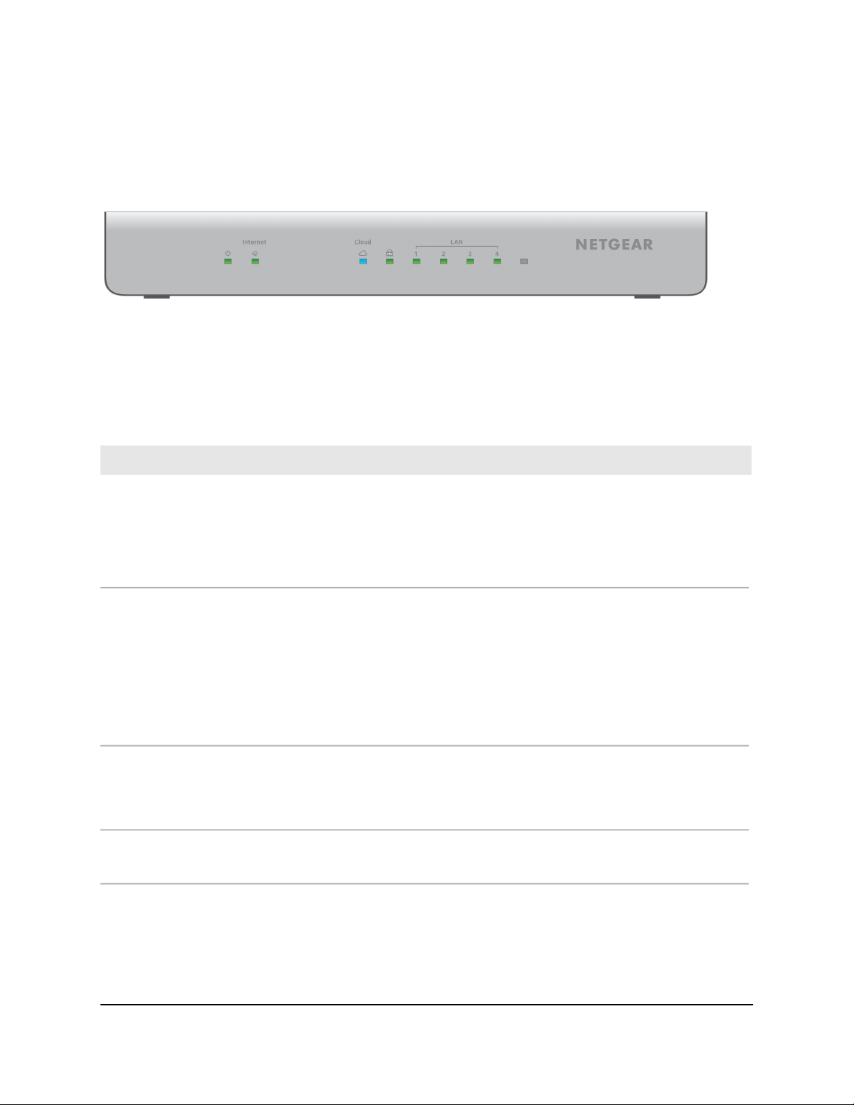
Front panel with LEDs
The front panel contains the status LEDs.
Figure 1. Front panel
The following table describes the LEDs.
Table 1. LEDs on the front panel
Power LED
WAN LED
Cloud Connection LED
VPN LED
DescriptionLED
Solid green. The router is powered on.
Blinking green. The router is booting or shutting down.
Solid amber. The router did not boot successfully.
Blinking amber. A firmware update is in progress.
Off. Power is not supplied to the router.
Solid green. The router established an Internet connection but is not processing Internet
traffic.
Blinking green. The router established an Internet connection and is transmitting or
receiving packets.
Solid amber. The router attempted but failed to establish an Internet connection.
Blinking amber. The router is in the process of establishing an Internet connection.
Off. No cable is not connected to the Internet port or the cable is not connected to an
Internet modem.
Solid blue. The router is connected to the cloud server and is set up to be managed by
NETGEAR Insight.
Off. The router is not connected to the cloud server or is set up to be managed by the
local browser interface.
Solid green. The router established a VPN connection.
Off. The router did not establish a VPN connection.
Hardware Installation Guide10Hardware Overview
Page 11

Insight Instant VPN Router BR500
Table 1. LEDs on the front panel (Continued)
DescriptionLED
LAN LEDs
Link, speed, and
activity for Ethernet
ports 1 to 4
Solid green. A valid 1 Gbps link is established.
Blinking green. The port is transmitting or receiving packets at 1 Gbps.
Solid amber. A valid 10 Mbps or 100 Mbps link is established.
Blinking amber. The port is transmitting or receiving packets at 10 Mbps or 100 Mbps.
Off. No link is established.
For future use.Rightmost LED
Back panel
The following figure shows the back panel.
Figure 2. Back panel
From left to right, the back panel contains the following components:
Recessed Reset button (see Reset button on page 12).
•
Four independent 10/100/1000BASE-T RJ-45 LAN ports (see RJ-45 ports for
•
10/100/1000M BASE-T Ethernet connectivity on page 12) for connections to devices
such as a switch, WiFi access point, ReadyNAS storage system, security camera, and
computer.
One independent 10/100/1000BASE-T RJ-45 WAN (Internet) port (see RJ-45 ports
•
for 10/100/1000M BASE-T Ethernet connectivity on page 12) for connection to an
uplink such as a cable or DSL modem.
DC power receptacle to be used with the power adapter that is provided with the
•
router.
•
On/Off power button.
Kensington lock for an optional security cable.
•
Hardware Installation Guide11Hardware Overview
Page 12

Insight Instant VPN Router BR500
RJ-45 ports for 10/100/1000M BASE-T Ethernet connectivity
All RJ-45 copper ports support autosensing. When you insert a cable into an RJ-45 port,
the router automatically ascertains the maximum speed (10 Mbps, 100 Mbps, or 1 Gbps)
and duplex mode (half-duplex or full-duplex) of the attached device. All ports support
a Category 5e (Cat 5e) cable (or higher-rated Ethernet cable) terminated with an 8-pin
RJ-45 connector.
To simplify the procedure for attaching devices, all RJ-45 ports support Auto Uplink
technology. This technology allows you to attach devices to the RJ-45 ports with either
straight-through or crossover cables.
When you insert a cable into the router’s RJ-45 port, the router automatically performs
the following actions:
Senses whether the cable is a straight-through or crossover cable.
•
For the four LAN Ethernet ports, determines whether the link to the attached device
•
requires a normal connection (such as when you are connecting the port to a
computer) or an downlink connection (such as when you are connecting the port to
a switch or WiFi access point).
Automatically configures the RJ-45 port to enable communications with the attached
•
device. The Auto Uplink technology compensates for setting uplink connections
while eliminating concern about whether to use crossover or straight-through cables
when you attach devices.
Reset button
The router provides a Reset button on the back panel so that you can return the router
to its factory default settings.
Caution: This process erases all settings that you configured in the router.
To reset the router to factory default settings:
1.
On the back of the router, locate the Reset button.
2.
Using a straightened paper clip, press and hold the recessed Reset button until the
Power LED lights amber, which takes about five seconds.
3.
Release the Reset button
Hardware Installation Guide12Hardware Overview
Page 13

Insight Instant VPN Router BR500
The Power LED starts blinking amber and the configuration is reset to factory default
settings. When the reset is complete, the router reboots. This process takes about
two minutes.
Hardware Installation Guide13Hardware Overview
Page 14

3
Applications
The router is designed to provide flexibility in configuring network connections. You
can use the router for remote VPN connections (for example, between a local office and
a remote worker), for site-to-site VPN connections (for example, between a local office
and a remote office), and as a Gigabit backbone router in a small to medium-sized
business network.
This chapter includes the following sections:
• Remote VPN connectivity
• Site-to-site VPN connectivity
• Edge routing for a small to medium-sized business
14
Page 15

Insight Instant VPN Router BR500
Remote VPN connectivity
With one router at a site, you can provide secure, encrypted VPN connections to up to
10 remote users. These users can access all resources that are connected to the router,
for example, file servers, ReadyNAS storage systems, security cameras, and so on.
After the router is connected to the Internet, you can use the NETGEAR Insight app or
Insight Cloud portal to discover the router on the network and add the router to the
Insight app and Insight Cloud portal.
Note: For an Insight managed network, the VPN authentication traffic requires a
connection with the NETGEAR cloud, but the actual data is transferred between the
remote client and the router and does not go through the NETGEAR cloud. If you use
an OpenVPN connection, the VPN authentication traffic does not require a connection
with the NETGEAR cloud.
The following figure shows the router providing edge routing and VPN connectivity for
remote users.
Figure 3. Remote VPN connectivity
Hardware Installation Guide15Applications
Page 16

Insight Instant VPN Router BR500
Site-to-site VPN connectivity
With two routers, each at a different site, you can create a site-to-site VPN, which means
that you can connect two local LANs and separate networks together as if they were
physically connected and colocated. A VPN group that consists of two routers can
support up to 20 remote users with access to both sites. These users can access all
resources that are connected to each router, for example, file servers, ReadyNAS storage
systems, security cameras, and so on.
After each router is connected to the Internet, you can use the NETGEAR Insight app
or Insight Cloud portal to discover each router on the network and add each router to
the Insight app and Insight Cloud portal.
Note: For an Insight managed network, the VPN authentication traffic requires a
connection with the NETGEAR cloud, but the actual data is transferred between the
routers at the sites and does not go through the NETGEAR cloud.
The following figure shows two routers providing edge routing, site-to-site VPN
connectivity, and VPN connectivity for remote users.
Figure 4. Site-to-site VPN connectivity
Hardware Installation Guide16Applications
Page 17

Insight Instant VPN Router BR500
Edge routing for a small to medium-sized business
Even if you do yet not need VPN connectivity, you can use the router as an edge router
with firewall functionality in a small to medium-sized business network that gives users
Gigabit-speed access to network devices and the Internet.
The following figure shows the router functioning as an edge router in a small business
network. The router is connected to the Internet over a modem. Two switches are
connected to the router, providing ReadyNAS storage connectivity, computer
connectivity, and WiFi connectivity through WiFi access points that are connected to
one of the switches.
After the router is connected to the Internet, you can use the NETGEAR Insight app or
Insight Cloud portal to discover the router on the network and add the router to the
Insight app and Insight Cloud portal.
Figure 5. Edge routing
Hardware Installation Guide17Applications
Page 18

4
Installation
This chapter describes the installation procedures for the router.
Router installation involves the steps that are described in the following sections:
• Step 1: Prepare the site
• Step 2: Protect against electrostatic discharge
• Step 3: Unpack the router
• Step 4: Install the router
• Step 5: Connect the router to a modem
• Step 6: Connect devices to the router
• Step 7: Check the installation
• Step 8: Apply power and check the LEDs
• Step 9: Configure and manage the router
18
Page 19

Insight Instant VPN Router BR500
Step 1: Prepare the site
Before you install the router, make sure that the operating environment meets the site
requirements that are listed in the following table.
Table 2. Site requirements
RequirementsCharacteristics
Mounting
Access
Power source
Cabling
Environmental
Desktop installations. Provide a flat table or shelf.
Wall installations. Use the wall-mount screws that are supplied with the router to attach
the router to a wall.
Pole (or other surface) installations. Use an off-the-shelf 100 mm VESA standard mount
to secure the router to a pole or another surface. The bottom panel of the router provides
four mount holes that are VESA-compliant.
Rack-mount installations. Use a 19-inch (48.3-centimeter) EIA standard equipment rack
that is grounded and physically secure. You also need the rack-mount kit that is supplied
with the router.
Locate the router in a position that allows you to access the ports and power connector
on the back panel and view the LEDs on the front panel.
Use the DC power adapter that is supplied with the router. Make sure that the AC outlet
in which you plug the power adapter is not controlled by a wall switch, which can
accidentally turn off power to the outlet and the router.
Route cables to avoid sources of electrical noise such as radio transmitters, broadcast
amplifiers, power lines, and fluorescent lighting fixtures.
Temperature. Install the router in a dry area with an ambient temperature between 32ºF
and 122ºF (0ºC and 50ºC). Keep the router away from heat sources such as direct sunlight,
warm-air exhausts, hot-air vents, and heaters.
Operating humidity. The maximum relative humidity of the installation location must
not exceed 90 percent, noncondensing.
Ventilation. Do not restrict airflow by covering or obstructing air inlets on the sides of
the router. Keep at least 2 inches (5.08 centimeters) free on all sides for cooling. The room
or wiring closet in which you install the router must provide adequate airflow.
Operating conditions. Keep the router at least 6 feet (1.83 meters) away from the nearest
source of electromagnetic noise, such as a photocopy machine.
Hardware Installation Guide19Installation
Page 20

Insight Instant VPN Router BR500
Step 2: Protect against electrostatic discharge
Warning: Static electricity can harm delicate components inside your system. To prevent
static damage, discharge static electricity from your body before you touch any of the
electronic components, such as the microprocessor. You can do so by periodically
touching an unpainted metal surface on the router.
You can also take the following steps to prevent damage from electrostatic discharge
(ESD):
When unpacking a static-sensitive component from its shipping carton, leave it in
•
the antistatic package until you are ready to install it. Just before unwrapping the
antistatic package, discharge static electricity from your body.
Before moving a sensitive component, place it in an antistatic container or package.
•
Handle all sensitive components in a static-safe area. If possible, use antistatic floor
•
pads, workbench pads, and an antistatic grounding strap.
Step 3: Unpack the router
The following figure shows the package contents.
Figure 6. Router package contents
Hardware Installation Guide20Installation
Page 21

Insight Instant VPN Router BR500
Check the contents of the boxes to make sure that all items are present before installing
the router.
To check the package contents:
1.
Place the container on a clean flat surface, and cut all straps securing the container.
2.
Unpack the hardware from the boxes by carefully removing the hardware and placing
it on a secure and clean surface.
3. Remove all packing material.
4.
Verify that the package contains the following items:
BR500 router
•
DC power adapter (varies by region)
•
Wall-mounting screws and anchors
•
Rack-mounting brackets
•
Rack-mounting screws and washers
•
Installation guide
•
Rubber footpads for tabletop installation
•
5.
If any item is missing or damaged, contact your local NETGEAR reseller for
replacement.
Step 4: Install the router
You can place the router on a flat surface, attach it to a wall, or install it in a standard
19-inch (48.26-centimeter) network equipment rack.
You can also use any off-the-shelf 100 mm VESA standard mount to secure the router
to a wall, a pole, or another surface.
Install the router on a flat surface
The router ships with four self-adhesive rubber footpads.
To install the router on a flat surface:
Stick one rubber footpad on each of the four concave spaces on the bottom of the
router.
The rubber footpads cushion the router against shock and vibrations. They also
provide ventilation space between stacked routers.
Hardware Installation Guide21Installation
Page 22
Insight Instant VPN Router BR500
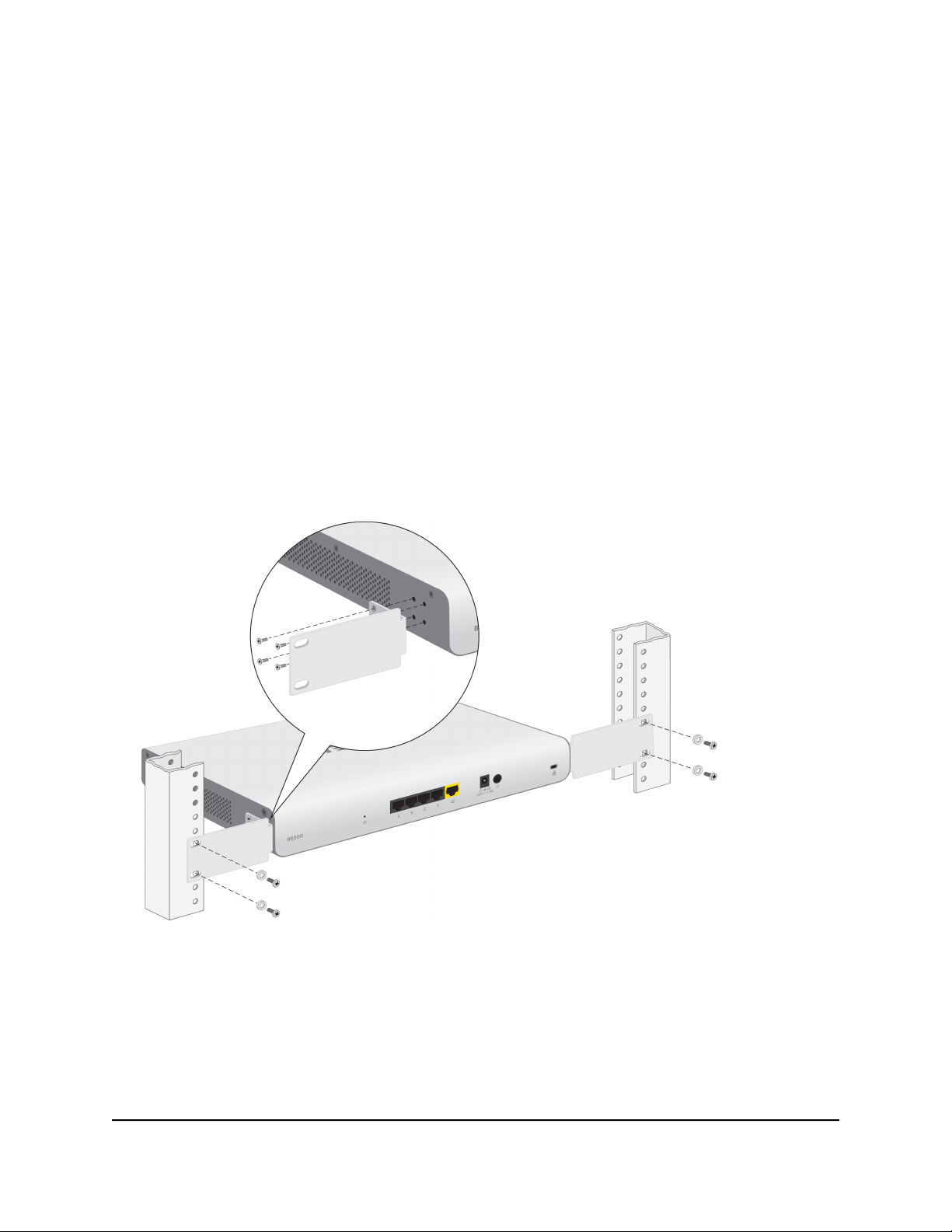
Install the router in a rack
To install the router in a rack, you need the 19-inch rack-mount kit supplied with the
router.
To install the router in a rack:
1.
Attach the supplied mounting brackets to the side of the router.
2. Insert the small screws provided in the product package through each bracket and
into the bracket mounting holes in the router.
The package provides eight small screws, four for each side.
3. Tighten the screws with a No. 2 Phillips screwdriver to secure each bracket.
4. Align the mounting holes in the brackets with the holes in the rack, and insert two
pan-head screws with nylon washers through each bracket and into the rack.
5. Tighten the screws with a No. 2 Phillips screwdriver to secure mounting brackets to
the rack.
Wall-mount the router
The bottom panel of the router provides four VESA mount holes that allow you to mount
the router to a wall. The router ships with wall-mount screws and anchors that you can
secure to a wall and attach the router to. We recommend that you use all four screws
for greater stability and correct positioning.
Hardware Installation Guide22Installation
Page 23

Insight Instant VPN Router BR500
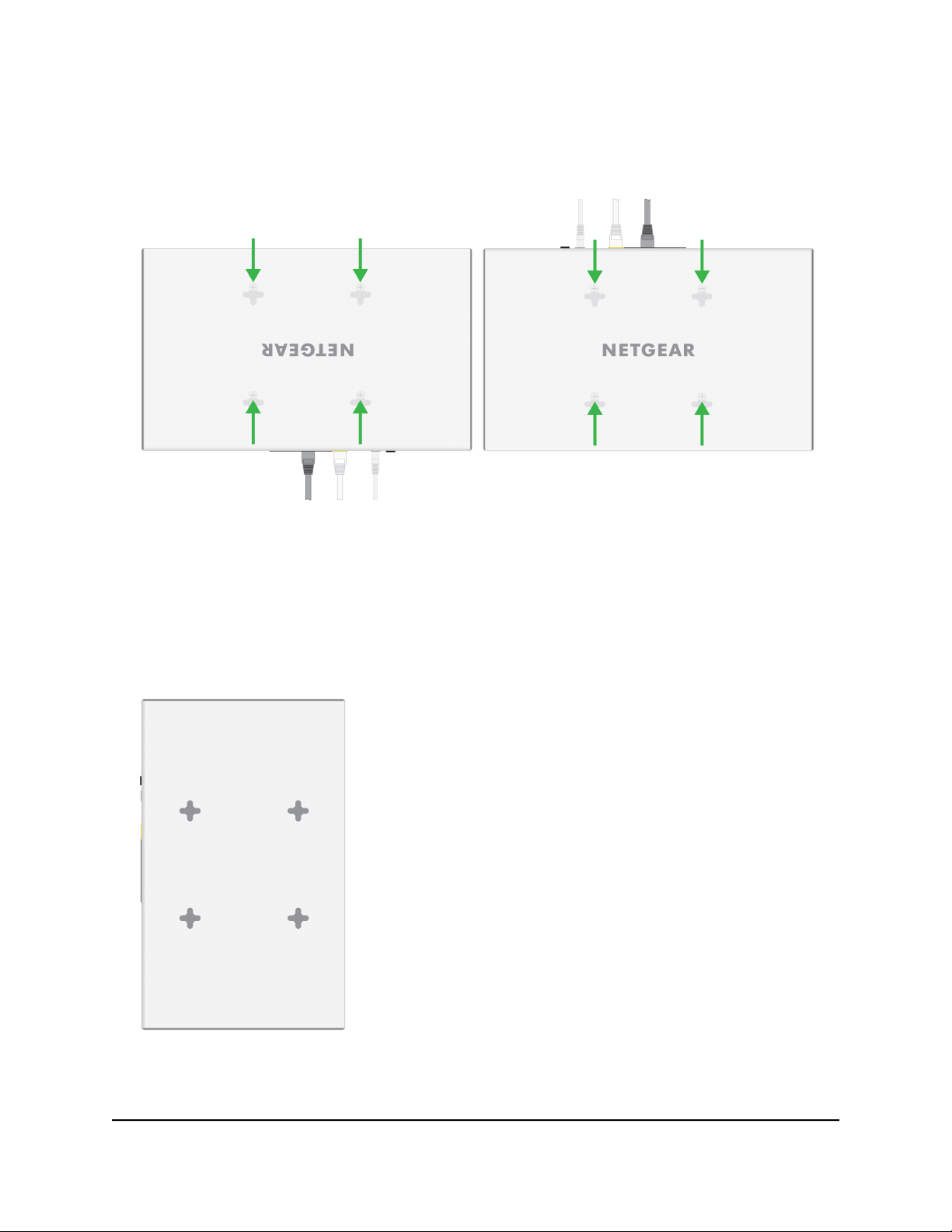
Wall-mount the router horizontally
You can mount the router horizontally to a wall with the cables either at the bottom or
top of the router.
To mount the router horizontally to a wall:
1.
Locate the four holes on the bottom panel of the router.
2.
Mark the four mounting holes on the wall where you want to mount the router.
The four mounting holes must be in a square at precise distances of 4 inches
(100 mm) from each other. In the following figure, each green arrow represents
100 mm.
3.
Drill holes into the wall for four anchors in which you will insert M4 x L25 mm screws.
The screws and anchors are in the router package.
4. Insert the anchors into the wall and tighten the screws with a No. 2 Phillips screwdriver.
Leave about ¼ inch (6 mm) of each screw protruded from the wall so that you can
insert the screws into the holes on the bottom of the router.
Hardware Installation Guide23Installation
Page 24
Insight Instant VPN Router BR500
5.
Line up the holes on the bottom panel of the router with the screws in the wall and
mount the router to the wall with the cables either at the bottom (see the left figure)
or top (see the right figure) of the router.
Wall-mount the router vertically
You can mount the router vertically to a wall with the cables either at the left or right of
the router.
To mount the router vertically to a wall:
1.
Locate the four holes on the bottom panel of the router.
2.
Mark the four mounting holes on the wall where you want to mount the router.
Hardware Installation Guide24Installation
Page 25
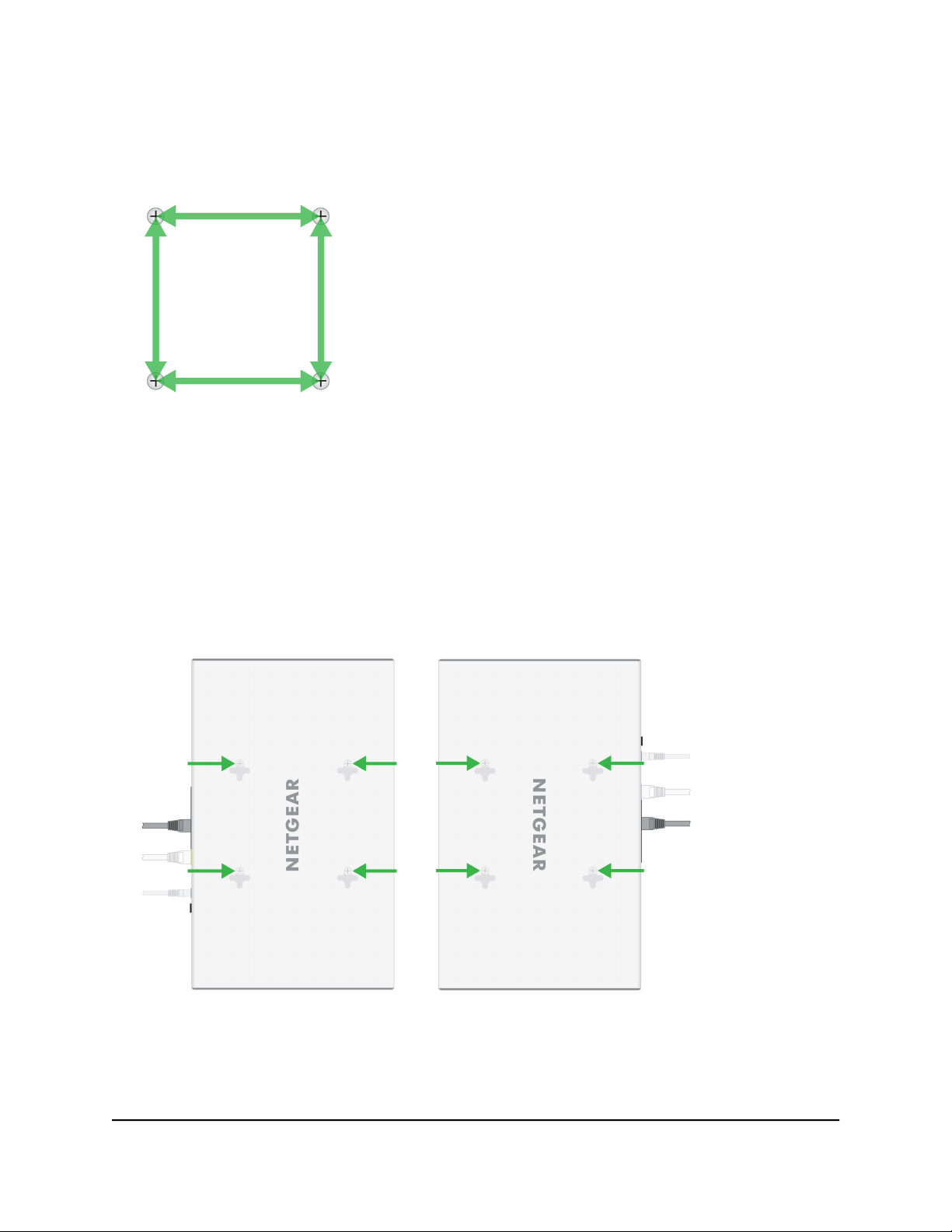
Insight Instant VPN Router BR500
The four mounting holes must be in a square at precise distances of 4 inches
(100 mm) from each other. In the following figure, each green arrow represents
100 mm.
3.
Drill holes into the wall for four anchors in which you will insert M4 x L25 mm screws.
The screws and anchors are in the router package.
4. Insert the anchors into the wall and tighten the screws with a No. 2 Phillips screwdriver.
Leave about ¼ inch (6 mm) of each screw protruded from the wall so that you can
insert the screws into the holes on the bottom of the router.
5.
Line up the holes on the bottom panel of the router with the screws in the wall and
mount the router to the wall with the cables either at the left (see the left figure) or
right (see the right figure) of the router.
Hardware Installation Guide25Installation
Page 26

Insight Instant VPN Router BR500
Mount the router to a pole or another surface
You can use an off-the-shelf 100 mm VESA standard mount to secure the router to a
pole or another surface. The bottom panel of the router provides four mount holes that
are VESA-compliant.
Step 5: Connect the router to a modem
The following procedure describes how to connect the router to a modem such as a
DSL or cable modem that provides Internet connectivity. The router’s RJ-45 WAN port
(the yellow port) supports Auto Uplink technology, which allows you to attach devices
using either straight-through or crossover cables. Use a Category 5 (Cat 5), Cat 5e, or
Cat 6 cable that is terminated with an RJ-45 connector.
Note: Instead of a modem, you can also use an existing LAN that provides Internet
connectivity. In that case, connect the cable from the LAN to the yellow Internet WAN
port on the router. For more information, see the user manual, which you can download
by visiting netgear.com/support/download/.
To connect a modem to the router’s RJ-45 WAN port:
1.
Unplug the modem’s power, leaving the modem connected to the wall jack for your
Internet service.
If the modem uses a battery backup, remove the battery.
2. Connect the modem to the RJ-45 WAN port on the router.
Ethernet specifications limit the cable length between the router and the Internet
modem to 328 feet (100 meters).
3.
Verify that the cable is installed correctly.
4.
If the modem uses a battery backup, put the battery back in the modem.
5. Plug in and turn on the modem.
Step 6: Connect devices to the router
The following procedure describes how to connect devices such as a switch, WiFi access
point, and computer to the router’s RJ-45 ports. The router supports Auto Uplink
technology, which allows you to attach devices using either straight-through or crossover
cables. Use a Category 5 (Cat 5), Cat 5e, or Cat 6 cable that is terminated with an RJ-45
connector.
Hardware Installation Guide26Installation
Page 27

Insight Instant VPN Router BR500
To connect devices to the router’s RJ-45 ports:
1. Connect a device to an RJ-45 port on the router.
Ethernet specifications limit the cable length between the router and the attached
device to 328 feet (100 meters).
2.
Verify that all cables are installed correctly.
Step 7: Check the installation
Before you apply power to the router, perform the following steps.
To check the installation:
1. Inspect the equipment thoroughly.
2.
Verify that all cables are installed correctly.
3.
Check cable routing to make sure that cables are not damaged or creating a safety
hazard.
4. Make sure that all equipment is mounted properly and securely.
Step 8: Apply power and check the LEDs
Before connecting the DC power adapter to the DC connector on the router, select an
AC outlet for the DC power adapter. Make sure that the AC outlet is not controlled by
a wall switch, which can turn off power to the router.
To apply power:
1.
Connect the plug of the DC power adapter to the DC power receptacle on the back
of the router.
2. Plug the DC power adapter into a power source such as a wall socket or power strip.
3.
If the router does not start, press the On/Off power button on the back panel.
4. Check to see that the LEDs on the router light correctly.
When you apply power, the Power LED on the router front panel lights and the port
LEDs for attached devices light.
Note: After you apply power, the Power LED blinks green while the router starts.
After two or three minutes, the router completes its startup process and the Power
LED turns from blinking green to solid green.
Hardware Installation Guide27Installation
Page 28

Insight Instant VPN Router BR500
If the Power LED does not light, check to see that the DC power adapter is plugged
in correctly and that the power source is good.
Step 9: Configure and manage the router
After you power on the router for the first time, you must use the local browser interface
to configure the WAN (Internet) connection of the router. For more information, see the
installation guide and user manual, which you can download from
netgear.com/support/download/.
After the router is connected to the Internet, you can discover the router on the network
using the NETGEAR Insight app. If you are an Insight Premium or Pro user, you can also
use the Cloud portal. These tools let you perform remote management and monitoring
tasks from your smartphone, tablet, or computer. For more information about Insight,
visit netgear.com/insight and see the NETGEAR knowledge base articles at
netgear.com/support/.
You can use the router without creating an Insight-managed topology (using the Insight
app or Insight Cloud portal), but in that situation you cannot remotely monitor, manage,
and troubleshoot the router, nor receive push notifications from the router, and the
router operates in standalone mode only, like a traditional router.
Using the Insight app and Insight Cloud portal, as well as network-based policies and
zero-touch configuration, you can configure and manage the router, along with
Insight-managed WiFi access points and NAS devices, at the network level. Also, using
the Insight app or Insight Cloud portal, you can improve the efficiency of the router,
which results in the improvement of its overall performance as well as the performance
of the network.
Note: The router’s default IP address is 192.168.1.1 and its default subnet mask is
255.255.255.0.
Hardware Installation Guide28Installation
Page 29

5
Troubleshooting
This chapter provides information about troubleshooting the switch. The chapter includes
the following sections:
• Hardware troubleshooting chart
• Additional troubleshooting suggestions
29
Page 30

Insight Instant VPN Router BR500
Hardware troubleshooting chart
The following table lists symptoms, possible causes, and possible solutions for hardware
problems that might occur.
Table 3. Troubleshooting chart
Possible SolutionPossible CauseSymptom
activity LED is off when the
port is connected to a device.
File transfer is slow or
performance is degraded.
A segment or device is not
recognized as part of the
network.
A combined speed and
activity LED is blinking
continuously on all
connected ports and the
network is disabled.
Power is not supplied to the router.Power LED is off.
Port connection is not working.A combined speed and
One possible cause is that a
broadcast storm occurred and that
a network loop (redundant path)
was created.
One or more devices are not
properly connected, or cabling does
not meet Ethernet guidelines.
A network loop (redundant path)
was created.
Check the power cable connections at the
router and the power source.
Make sure that all cables are used correctly
and comply with the Ethernet specifications.
Check the crimp on the connectors and make
sure that the plug is properly inserted and
locked into the port at both the router and
the connecting device.
Make sure that all cables are used correctly
and comply with the Ethernet specifications.
Check for a defective port, cable, or module
by testing them in an alternate environment
where all products are functioning.
Break the loop by making sure that only one
path exists from any networked device to any
other networked device.
Verify that the cabling is correct.
Make sure that all connectors are securely
positioned in the required ports. It is possible
that equipment was accidentally
disconnected.
Break the loop by making sure that only one
path exists from any networked device to any
other networked device.
Hardware Installation Guide30Troubleshooting
Page 31

Insight Instant VPN Router BR500
Additional troubleshooting suggestions
If the suggestions in the troubleshooting chart do not resolve the problem, see the
following troubleshooting suggestions:
Network adapter cards. Make sure that the network adapters that are installed in
•
the computers are in working condition and the software driver was installed.
Configuration. If problems occur after you alter the network configuration, restore
•
the original connections and determine the problem by implementing the new
changes, one step at a time. Make sure that cable distances, repeater limits, and
other physical aspects of the installation do not exceed the Ethernet limitations.
Router integrity. If necessary, verify the integrity of the router by resetting it. To
•
reset the router, press the On/Off power button twice. If the problem continues,
contact NETGEAR technical support. For more information, visit the support website
at netgear.com/support.
Autonegotiation. The RJ-45 ports negotiate the correct duplex mode, speed, and
•
flow control if the device at the other end of the link supports autonegotiation. If the
device does not support autonegotiation, the router determines only the speed
correctly, and the duplex mode defaults to half-duplex.
The Gigabit Ethernet ports negotiate speed, duplex mode, and flow control if the
attached device supports autonegotiation.
Hardware Installation Guide31Troubleshooting
 Loading...