

Page 1
Installation
NETGEAR Power Supplies Units for
Managed Switches
APS150W, APS250W, APS550W, APS1000W, APS600W,
and APS1200W
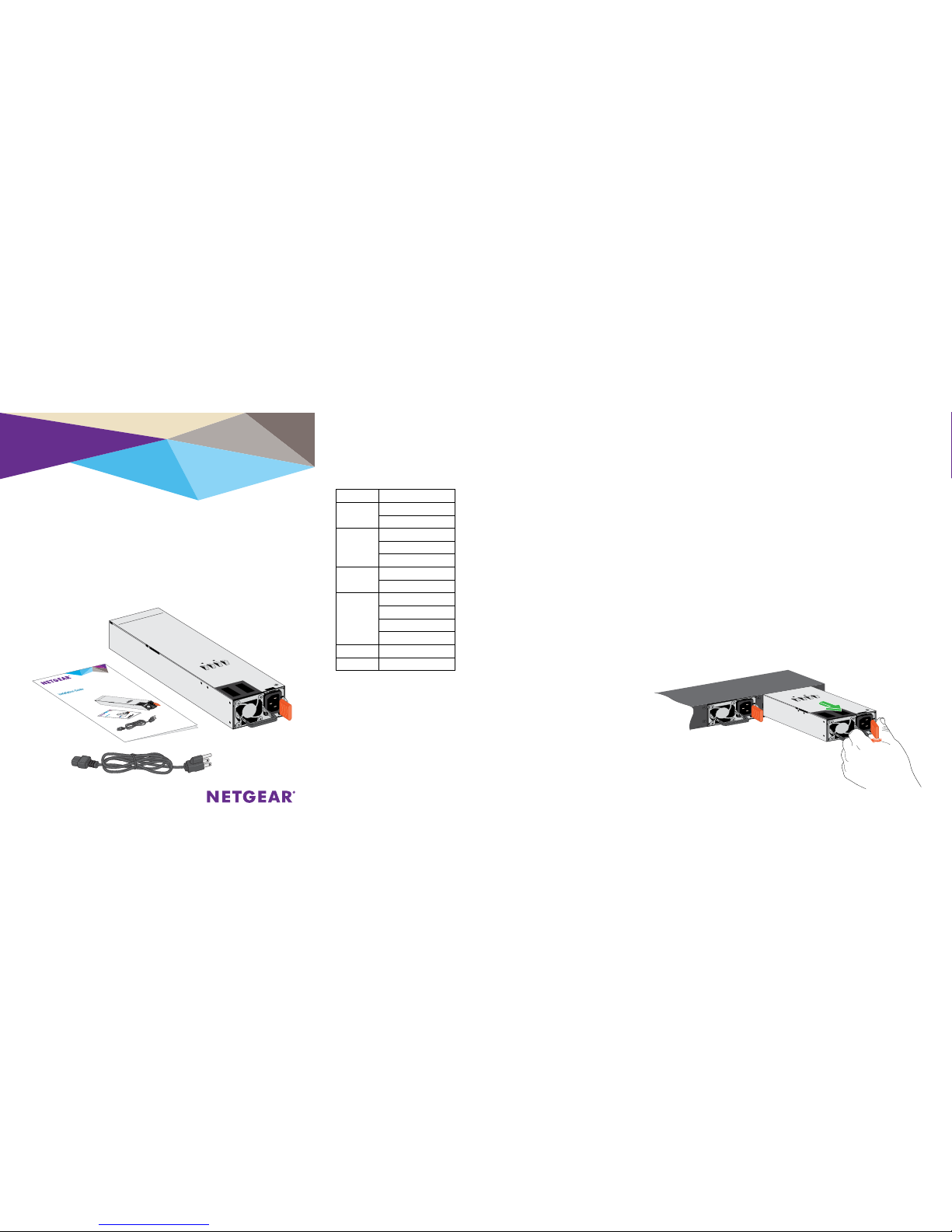
Power Supply Unit Overview
The following table provides an overview of the power supply units (PSUs)
for managed switches and the models in which they are supported.
PSU Model Used in Switch Model
APS150W M4300-28G
M4300-52G
APS250W M4300-8X8F
M4300-12X12F
M4300-24X24F
APS550W M4300-28G-POE+
M4300-52G-POE+
APS1000W M4300-28G-POE+
M4300-52G-POE+
M6100-3S
RPS4000v2
APS600W M4300-96X
APS1200W M4300-96X
Install an Additional Power Supply Unit
In models with more than one power supply bay, you can install an
additional PSU.
¾ To install an additional PSU:
1. Pull out the cover plate from the power module bay in which you want
to insert the additional PSU.
2. Insert the additional PSU into the power module bay, and gently push
the PSU into the bay.
AC OK LED. All PSUs provide one AC
OK LED. During normal operation, this
LED lights green to indicate that the
PSU is receiving power.
DC OK LED. Model APS150W also
provides one DC OK LED. During
normal operation, this LED lights green
to indicate that the DC outputs are
within regulation limits.
Package Contents
CAUTION: When inserting the PSU, do not use unnecessary force. Doing so
can damage the connectors on the back of the PSU and on the midplane.
3. Connect the end of the power cord to the power receptacle on the PSU.
4. Plug the AC power cord into a power source such as a wall socket or power
strip.
When you apply power, both the AC OK LED on the PSU and the switch’s
Power LED that is associated with the power supply bay light. If these LEDs
do not light, make sure that the power cord is plugged in correctly and that
the power source is good.
Replace a Power Supply Unit
In models with more than one PSU, the PSUs are hot-pluggable.
¾ To replace a PSU:
1. If your switch functions with a single PSU only, disconnect the power cord
from the PSU and let the switch power down.
If your switch functions with more than one PSU, you do not need to power
down the switch and you can perform a hot swap.
2. Remove the PSU from the power module bay by moving the orange release
latch to the le and pulling the extraction handle.
Page 2
NETGEAR INTL LTD
Building 3, University Technology Centre
Curraheen Road, Cork, Ireland
NETGEAR, Inc.
350 East Plumeria Drive
San Jose, CA 95134, USA
© NETGEAR, Inc., NETGEAR and the NETGEAR Logo
are trademarks of NETGEAR, Inc. Any non‑NETGEAR
trademarks are used for reference purposes only.
January 2018
3. Insert the replacement PSU into the power module bay, and gently push
the PSU into the bay until the latch locks.
CAUTION: When inserting the PSU, do not use unnecessary force.
Doing so can damage the connectors on the back of the PSU and on the
midplane.
4. Connect the end of the power cord to the power receptacle on the PSU.
5. Plug the AC power cord into a power source such as a wall socket or
power strip.
When you apply power, both the AC OK LED on the PSU and the
switch’s Power LED that is associated with the power supply bay light.
If these LEDs do not light, make sure that the power cord is plugged in
correctly and that the power source is good.
Power Supply Unit Technical Specifications
Specification PSU
AC input • APS150W. 100–127VAC, 3A, 50–60 Hz or 200–240VAC, 1.5A,
50–60 Hz
• APS250W. 100–240VAC, 3.5–2A, 50–60 Hz
• APS550W. 100–240VAC, 9–4A, 50–60 Hz
• APS1000W. 100–127VAC, 9.9A, 50–60 Hz or 200–240VAC, 7.8A,
50–60 Hz
• APS600W. 90–132VAC, 8A, 47–63 Hz or 180–264VAC, 4A,
47–63 Hz
• APS1200W. 90–132VAC, 15A, 43–67 Hz or 180–264VAC, 8A,
43–67 Hz
DC output • APS150W. +12V 12.5A
• APS250W. +12V 20A or +12 VSB 1A
• APS550W. +54V 10.95A or +12 VSB 2.08A
• APS1000W. 56V 12.12A or +12 VSB 1.8A (@ 100–127VAC)
56V 17.35A or +12 VSB 2.4A (@ 200–240VAC)
• APS600W. +54.5 VDC, 11A
• APS1200W. +54.5 VDC, 22A @ 230 VAC, or 18.35A @ 115 VAC
Specification PSU
Dimensions
(H x W x D)
• APS150W. 1.5 x 2.0 x 7.3 in. (39 x 50.5 x 185 mm)
• APS250W. 1.5 x 2.9 x 7.3 in. (39 x 74 x 185 mm)
• APS550W. 1.64 x 3.6 x 8.65 in. (39.3 x 86.36 x 207.56 mm)
• APS1000W. 1.64 x 3.6 x 8.65 in. (39.3 x 86.36 x 207.56 mm)
• APS600W and APS1200W 2.87 x 7.28 x 1.57 in.
(73 x 185 x 39.8 mm)
Operating
temperature
• APS150W. 23 to 122ºF (–5 to 50ºC)
• APS250W. 32 to 122ºF (0 to 50ºC)
• APS550W and APS1000W. 23 to 122ºF (–5 to 50ºC)
• APS600W and APS1200W. 23 to 122ºF (–5 to 50ºC)
Operating relative
humidity
• APS150W. Up to 95% noncondensing
• APS250W, APS550W, and APS1000W. 5% to 95% noncondensing
• APS600W and APS1200W. 5% to 95% noncondensing
Operating altitude
level
• APS150W. Below 16,000 feet (5,000 m) above sea level
• APS250W, APS550W, and APS1000W. Below 9,800 feet
(3,000 m) above sea level
• APS600W and APS1200. Below 16,000 feet (5,000 m) above sea
level
Storage
temperature
• APS150W and APS250W. –40 to 158ºF (–40 to 70ºC)
• APS550W and APS1000W. –40 to 185ºF (–40 to 85ºC )
• APS600W and APS1200W. –40 to 185ºF (–40 to 85ºC )
Storage altitude
level
Below 49,000 feet (15,000 m) above sea level
MTBF 4,534,733 hrs (~517 years) @ 77ºF (25ºC)
Support
Thank you for purchasing this NETGEAR product. You can visit
www.netgear.com/support to register your product, get help, access the latest
downloads and user manuals, and join our community. We recommend that you
use only ocial NETGEAR support resources.
Si ce produit est vendu au Canada, vous pouvez accéder à ce document en
français canadien à http://downloadcenter.netgear.com/other/.
(If this product is sold in Canada, you can access this document in Canadian
French at http://downloadcenter.netgear.com/other/.)
For the current EU Declaration of Conformity, visit
http://support.netgear.com/app/answers/detail/a_id/11621/.
For regulatory compliance information, visit
http://www.netgear.com/about/regulatory/.
See the regulatory compliance document before connecting the power supply.
Compliance
Safety
IEC 60950-1, EN 60950-1, CB Certificate/Report, UL/CSA 60950-1
CE Low Voltage Directive 2006/95/EC (Europe)
CCC (China)
KC (Korea)
EMC
FCC / ICES-003 Emission (USA/Canada)
CRISP 22 Emission (International)
EN55022 Emission (Europe)
EN55024 Immunity (Europe)
EN61000-4-2 Electrostatic Discharge
EN61000-4-3 Radiated RFI Immunity
EN61000-4-4 Electrical Fast Transients level 4
EN61000-4-5 Electrical Surge Level
EN61000-4-6 RF Conducted
EN61000-4-8 Power Frequency Magnetic Fields
EN61000-4-11 Voltage Dips and Interruptions
EN61000-4-8 Power Frequency Magnetic Fields
EN61000-4-11 Voltage Dips and Interruptions
EN61000-3-2 Harmonics (Europe)
EN61000-3-3 Voltage Flicker (Europe)
 Loading...