

Page 1
14 dBi Patch Panel Directional Antenna
ANT24D18v2
Installation Guide
Page 2
Introduction
Thank you for purchasing the NETGEAR ANT24D18v2 antenna. This Installation Guide
provides installing instructions and guidelines for using the NETGEAR 14 dBi Patch Panel
Directional Antenna.
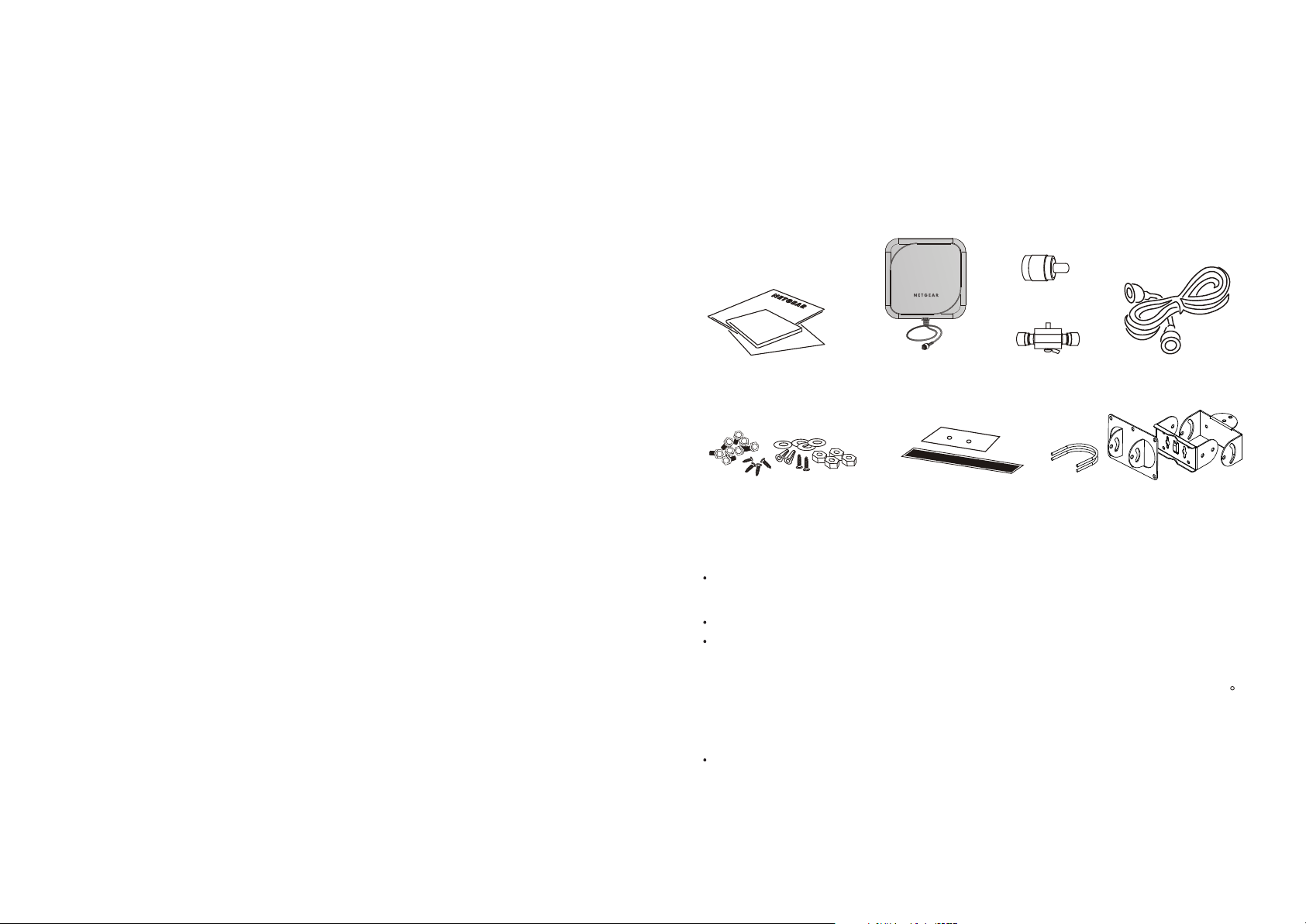
Package Contents
Reverse N/SMA
adapter
Installation Guide, Warranty and
Support information card
Screws, angle adj screws, screw nuts, washer,
plastic fixings,
14 dBi Patch Panel Directional
Antenna ANT24D18v2
Sticker and waterproof tape
Lightning
arrestor
3 brackets for adjustable positioning, and 2 U-bolts
2-meter cable
The package should contain the following items:
NETGEAR Indoor/Outdoor 14 dBi 2.4 ~ 2.5 GHz
Patch Panel Directional Antenna ANT24D18v2
2-meter low loss antenna cable to connect the antenna to a lightning arrestor
Lightning Arrestor
Note: a ground cable is not included but required for outdoor installation. The grounding
cable must be equivalent or better than: AWG 10, UL 1015, Stranded, 600 V, 105 C,
green or green/yellow insulation, 2 clip of 5.5 mm inner diameter cramped at both ends,
cable no longer than 5 meters.
Reverse N/SMA Adapter
1
Page 3
3 brackets for adjustable positioning, and 2 U-bolts
Screws, angle adj screws, screw nuts, washer, and plastic fixings,
Installation Guide
Warranty/Support Information card
If any of the parts are incorrect, missing, or damaged, contact your NETGEAR dealer.
Keep the carton, including the original packing materials, in case you need to return the
product for repair.
Antenna cable for connecting the wireless device is sold separately. Please use a NETGEAR
model ACC-10314-01, 02, 03, or 04 cable.
To obtain optimal results in extending wireless range with antenna installations, consult a
qualified professional installer for site survey and installation assistance.
In the U.S., the ANT24D18v2 antenna should only be used with devices that have been FCC
approved for use with it. Please check the NETGEAR web site at
http://www.NETGEAR.com/go/antennas_fcc for an updated list of FCC approved devices.
For Europe, use of any antenna requires careful planning and extra consideration to comply
with EU emissions and health standards and regulations. Antenna installation must comply
with the maximum level authorized by each country. Please check the NETGEAR web site at
http://www.NETGEAR.com/go/antennas_eu for a list of restrictions and approved devices.
Configuration and Placement
1
1
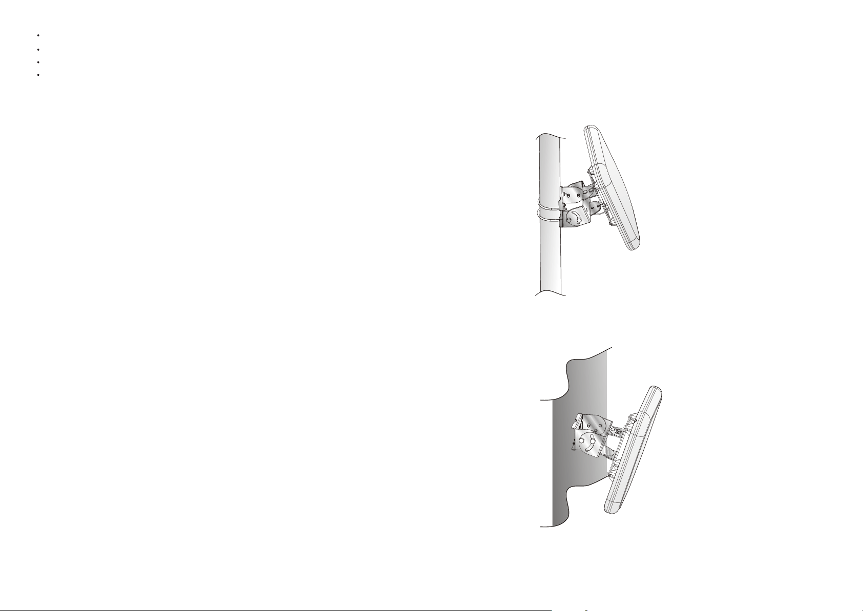
Pole Mount Configuration
This illustration shows the pole mount configuration option.
Wall Mount Configuration With Adjustable Brackets
This illustration shows the wall mount configuration with adjustable brackets.
325
Page 4
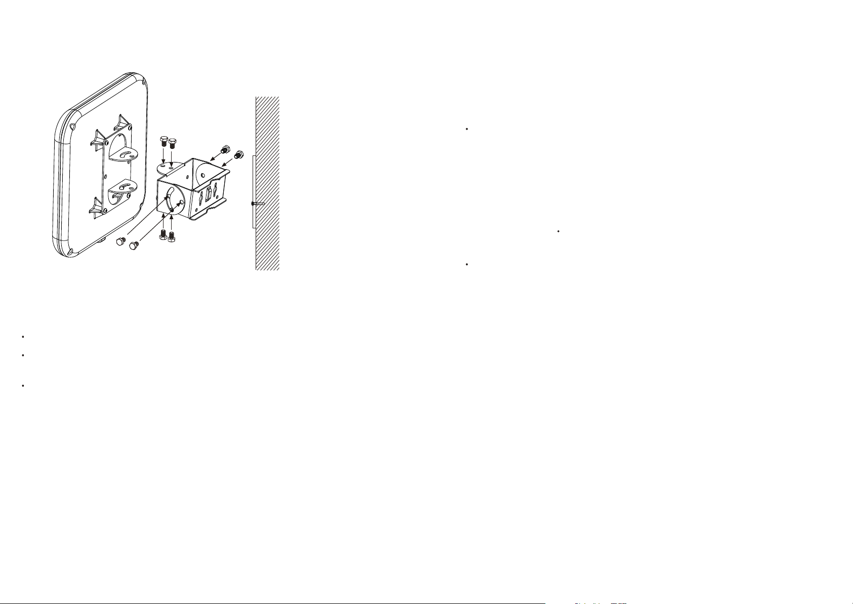
Wall Mount Configuration With Fixed Brackets
This illustration shows the wall mount configuration with brackets.
Placement and Other Important Considerations
Before installing your wireless antenna, observe the placement considerations. Antenna
placement dramatically affects potential coverage. Follow these guidelines to maximize coverage:
Place the ANT24D18v2 in a vertical position, connector toward the bottom.
Minimize the obstructions in the front of the antenna. There should be a good visual line
of sight and maximum open space between the ANT24D18v2 and the other antenna(s).
Outdoor point-to-point application (bridging, repeater mode, building to building, etc.):
Miles of outdoor range can be obtained when the antennas are installed properly. Fix the
antenna on the top of a building on a pole or on an external wall. Provide a good visual
line of sight between the ANT24D18v2 and the other antenna (max. open space) and ideally
no partial obstruction. Coverage increases as follow:
- Use the 14 dBi one side with long antenna cable. For instance WG302, 10 m cable
ACC-10314-04, lightning arrestor, 2m cable, and ANT24D18v2 on one side and
WG302 (with own antennas) on the other side.
- More range: Use the 14 dBi one side with short antenna cable. For instance WG302,
1.5m cable ACC-10314-01, lightning arrestor, 2m cable, and ANT24D18v2 on one
side and WG302 (with own antennas) on the other side.
- Super range: Use the 14 dBi both side with short/medium antenna cable. For instance
WG302, 3m cable ACC-10314-02, lightning arrestor, 2m cable, and ANT24D18v2 on
both sides.
Outdoor point-to-point alternative, antennas indoor behind windows: Place the 14 dBi indoor
behind a clean window (no metal coating) in both buildings and facing each other. Use a
short/medium antenna cable and fix the antenna on a tripod. Alternatively the 14 dBi can
be placed on a wall just behind the window (no more than 3 meters (10 ft)). Furthermore,
the antennas should be located high in the building close the top. One example: WG302,
3m cable ACC-10314-02 and ANT24D18v2 on both sides. Please account for less range
than outdoor (30-70 % less range).
Outdoor Note: Ground cable is not provided but is required. Use AWG 10, UL 1015,
Standard 600 V, 105 C, green or green/yellow insulation, 2 clips with a 5.5 mm inner
diameter clamped at both ends, and cable no longer than 5 meters.
Indoors: Place the antenna on a wall or pole, facing the area to cover at 2 meters or higher
above the floor. Place the ANT24D18v2 above cubicle level with the maximum open space
in its front. Ideally, it should be located outside an IT data center or outside a room with
multiple metal partitions. Use a NETGEAR antenna cable of up to 10 m length to
connect the antenna to the wireless access point/router.
- Indoor bridging in an airport terminal, train station terminal, warehouse, exhibition
hall: Highest indoor range can be achieved when there is a good visual line of sight
and maximum open space in between the antennas. One example: WG302, 3m cable
ACC-10314-02 and ANT24D18v2 on both sides. Can greatly increase range vs. 2
WG30 2 only.
- Indoor bridging where there is less than 15 ft open space (narrow hall, large room
office with low ceiling): WLAN communication can suffer from multiple reflections
which are environment, orientation and time dependent, called multipath fading. In
this case, 2 ANT24D18v2 per wireless node (requires both primary and secondary RF
ports) can improve the range and throughput by providing spatial diversity.
4
Page 5

Warning, Indoor point to multipoint: the ANT24D18v2 is not omnidirectional and is not
suitable when low ceilings, partial obstructions, walls, cubicles, large metal objects, etc. are
present. WLAN communications can suffer from multiple reflections, which are
orientation, environment and time dependent.
The best performance is achieved with a short cable between the antenna and the wireless
device. The shortest approved cable to be used in conjunction with the ANT24D18v2 in
North America is the NETGEAR 1.5 m (ACC-10314-01) cable.
The antenna should be installed so that it is a minimum of 50 cm (20 inches) away
from people.
Installing the 14 dBi Patch Panel
2
2
There are two parts to the wireless antenna installation process:
fixed brackets.
outdoo rs.
Follow the instructions in this section of the manual to install your antenna.
First, Mount the Antenna
Pole Mount Installation
Directional Antenna
Mount the antenna on a pole, or on a wall with adjustable brackets, or on a wall with
Connect the appropriate electrical hardware depending on if the installation is indoors or
6
7
Page 6

Wall Mount with Adjustable Bracket
Now, Connect the Antenna
The instructions below cover outdoor and indoor installations.
Connecting the Antenna for an Outdoor Installation
1. Turn off your wireless unit.
2. Connect the provided 2-meter cable to the antenna and to the arrestor as shown here. You
can connect the cable to either of the two RF ports on the lightning arrestor.
14 dBi Patch Panel
Directional Antenna
Wireless unit's
DC block
ANT24D18v2
45cm cable
(provided)
Wireless unit
Ethernet
(CAT 5) cable
N/SMA adapter
NETGEAR cable
ACC-10314-01, 02, 03, 04, 05
(Sold separately)
Lightning
arrestor
Ground cable
(Not provided)
2m cable
(provided)
Building
grounding
3. Connect the grounding cable (not included) from the lightning arrestor to the ground of
the building.
Grounding cable: The grounding cable must be equivalent or better than: AWG 10, UL
1015, Stranded, 600 V, 105 C, green or green/yellow insulation, 2 clip of 5.5 mm inner
diameter cramped at both ends, cable no longer than 5 meters.
Warning: the lightning arrestor and appropriate ground cable must be used for outdoor
installation. NETGEAR does not assume any responsibility in case of hazard resulting of
non-compliance with these instructions.
4. Screw the N/SMA Reverse Adapter on the lightning arrestor (clockwise) on the second RF
port. Connect a NETGEAR cable model ACC-10314-01, 02, 03, 04 or 05 (sold
separat ely) to the adapter.
5. Locate the primary detachable antenna on the wireless access point. Remove the antenna
and connect the other end of the NETGEAR cable ACC-10314-01, 02, 03, 04 or 05 to
this port.
8
9
Page 7

Note: On access points with two antennas, if you are only replacing one antenna, be sure
to replace the primary antenna and do not remove the secondary antenna.
6. If connecting 2 ANT24D18v2 antennas: repeat step 2 to 5 for the second antenna and
connect it the secondary port. If the wireless device supports transmit/receive on both
ports, the 2 antennas can be used to cover 2 separate or partial overlapping WLAN areas.
For instance the 2 ANT24D18v2 could be oriented at 90 degrees and positioned 50 feet
away and using the WG302 access point. The 2 antennas can also be used to provide
spatial diversity.
If the wireless device transmits only with the primary antenna port, the 2 ANT24D18v2
antennas can be used only for spatial diversity.
Spatial diversity: place the 2 antennas 3 to 9 feet away and oriented toward the same direction.
7. After attaching your new 14 dBi antenna(s), reconnect your wireless device to the network
and turn it on.
Connecting the Antenna for an Indoor Installation
1. Turn off your wireless unit.
2. Connect the reverse N/SMA adapter to the antenna.
3. Connect a NETGEAR antenna cable model ACC-10314-01, 02, 03 or 04 to the reverse
N/SMA adapter.
4. Locate the primary detachable antenna of the wireless device. Remove the antenna and
connect the other end of the NETGEAR cable ACC-10314-01, 02, 03 or 04 to
this port.
Note: On access points with two antennas, if you are only replacing one antenna, be sure
to replace the primary antenna and do not remove the secondary antenna.
5. If connecting 2 ANT24D18v2 antennas: repeat step 2 to 4 for the second antenna and
connect it the secondary port. If the wireless device supports transmit/receive on both
ports, the 2 antennas can be used to cover 2 separate or partial overlapping WLAN areas.
For instance the 2 ANT24D18v2 antennas could be oriented at 90 degrees and positioned
50 feet away and using the WG302 access point. The 2 antennas can also be used to
provide spatial diversity.
If the wireless device transmits only with the primary antenna port, the 2 ANT24D18v2
antennas can be used only for spatial diversity.
Spatial diversity: place the 2 antennas 3 to 9 feet away and oriented toward the
same direction.
6. After attaching your new 14 dBi antenna(s), reconnect your wireless device to the network
and turn it on. The provided 2m cable and lightning arrestor should not have been used.
10
NETGEAR antenna cable
ACC-10314-01, 02, 03, 04
or 05 (sold separately)
14 dBi Patch Panel
Directional Antenna
ANT24D18v2
Wireless Access Point
Antenna Connection
11
Page 8

Specifications
3
3
This chapter provides the
14 dBi Patch Panel Directional
Antenna specifications.
Description
Frequency Range
Ty p e
Beam Width
Impedance
SWR
Return Loss
Gain
Maximum Input Power
Polarization
Connector Type
Dimensions
Hardware Included
Antenna Color
Rust Proof
Water Proof
Operating Temperature
Storage Temperature
Humidity
RoHS Compliant
14 dBi Patch Panel
Directional Antenna
ANT24D18v2 and
Hardware
14 dBi Patch Panel Directional Antenna
and Mounting Assembly
2400 - 2500MHz
Directional
33 horizontal, 30 vertical
50 Ohms nominal
1.92 maximum
<
-10 dB
14 dBi
20 W (with 45 cm cable & Rev. N-Type connector)
Vertical
Reverse N Female
262 x 240 x 30 (mm)
6 screws, 1 set holder, 8 angle adj screws, 4 screw nuts, 4 washers,
2 plastic fixings, 2 U-bolts, 1 sticker, 1 waterproof tape.
Gray
Hardware is rust proof
Rain Resistant
-20 C to +65 C (-4 F to 149 F)
-30 C to +75 C (-22 F to 167 F)
5 to 95% RH
Ye s
Description
Frequency Range
VSWR
Cable Type
Transmission Loss
Connector Type
Max. Working Voltage
Minimum Bend Radius
Jacket
Recommended Coupling Nut Torque
Connector Body & Contact
Insulation
Operating Temperature / Humidity
Transportation Temperature / Humidity
Storage Temperature / Humidity
Water Proof
RoHS Compliant
2m cable
2 Meter Antenna Cable
0 - 3 GHz
1.5 max.
CFD200 (Commate)
2.2 dB max. @ 2.4 - 2.5 GHz
2 N type Male reverse
250 Vrms min.
25 mm (1 in)
PVC
35 cm.kgf * to 3.4 cm.kgf *
Brass Ni
PTF
-30 C to 75 C (-22 F to 167 F) / 20 to 95% RH
-30 C to 75 C (-22 F to 167 F) / 20 to 95% RH
-30 C to 75 C (-22 F to 167 F) / 20 to 95% RH
Rain Resistant
Ye s
12
13
Page 9

Lightning arrestorN/SMA Adapter Accessory
Description
Frequency Range
VSWR
Connector Type
Insulation Resistance
Center Contact Resistance
Outer Contact Resistance
Working Voltage
Impedance
Body & Center Contacts
Insulation
Gasket
Operating Temperature
Storage Temperature
Water Proof
RoHS Compliant
N/SMA Adapter Accessory
0 - 3 GHz
1.5 max.
N type Male reverse to SMA Female reverse
5000 Megohms min
6 milliohms max
2 milliohms max
500 V
50 Ohm
Brass
PTFE
Silicone Rubber
-40 C to 80 C (-40 F to 176 F)
-40 C to 80 C (-40 F to 176 F)
Rain Resistant
Ye s
Description
Frequency Range
VSWR
Insertion Loss
Impulse Breakdown Voltage
Max. Power Rating
Impedance
Insulation Resistance
Max. Withstanding Current
Overvoltage Protection
Connectors
Color
Operating Temperature
Storage Temperature
Water Proof
RoHS Compliant
Lightning Arrestor
0 - 6 GHz
1.5 max.
1.3 dB max.
110V min. (Voltage on upgrade ratio @500V/s)
200 W
50 Ohms
1000 MOhms
5000 A, 8/20
90V min. (100mA, < 150ms)
N type Female Reverse
Silver
-40 C to 80 C (-40 F to 176 F)
-40 C to 80 C (-40 F to 176 F)
Rain Resistant
Ye s
s
14
15
Page 10

Radiation Pattern: Elevation (Vertical plane)
90
105
120
135
150
165
180
195
210
225
240
255
75
dB
0 10
-10
-20
270
60
45
30
15
0
345
330
315
300
285
Radiation Pattern: Azimuth (Horizontal plane)
0
330
315
300
285
270
255
15345
30
45
-20 -10 0 10
60
75
90
dB
105
Statement of Conditions
In the interest of improving internal design, operational function, and/or reliability, NETGEAR reserves the right to
make changes to the products described in this document without notice. NETGEAR does not assume any liability
that may occur due to the use or application of the product(s) or circuit layout(s) described herein.
Federal Communications Commission (FCC) Compliance Notice:
Radio Frequency Notice
This device complies with part 15 of the FCC Rules. Operation is subject to the following two conditions:
1. This device may not cause harmful interference.
2. This device must accept any interference received, including interference that may cause undesired operation.
In the U.S., the ANT24D18v2 antenna should only be used with devices that have been FCC approved for use with it.
Please check the NETGEAR web site at http://www.NETGEAR.com/go/antannas_fcc for an updated list of FCC
approved devices.
This equipment has been tested and found to comply with the limits for a Class B digital device, pursuant to part 15
of the FCC Rules. These limits are designed to provide reasonable protection against harmful interference in a
residential installation. This equipment generates, uses, and can radiate radio frequency energy and, if not installed and
used in accordance with the instructions, may cause harmful interference to radio communications. However, there is
no guarantee that interference will not occur in a particular installation. If this equipment does cause harmful
interference to radio or television reception, which can be determined by turning the equipment off and on, the user is
encouraged to try to correct the interference by one or more of the following measures: (1) Reorient or relocate the
receiving antenna, (2) Increase the separation between the equipment and receiver, (3) Connect the equipment into an
outlet on a circuit different from that to which the receiver is connected, (4) Consult the dealer or an experienced
radio/TV technician for help.
Federal Communications Commission (FCC) and European Radiation
Exposure Statements
This equipment complies with FCC radiation exposure limits set forth for an uncontrolled environment. In order to
avoid the possibility of exceeding the FCC radio frequency exposure limits, human proximity to the antenna shall not
be less than 50 cm (20 inches) during normal operation. This device should not be co-located with other transmitters.
European Emission Statement
For EU, use of any antenna requires careful planning and extra consideration to comply with EU emissions, health
standards and regulations. It is recommended that a qualified professional installer service is consulted for site survey
and proper installation. Antenna installation must comply with the maximum level authorized by each country. See
http://www.NETGEAR.com/go/antannas_eu for product combinations that comply with EU regulations.
Safety
The NETGEAR wireless devices WG302, FWG114P, FVM318, ME103, and FM114P have been tested with the
antenna ANT24D18v2 and have successfully passed all relevant tests contained in the Standard for the Safety of
Information Technology Equipment for Europe (EN 60950-2000) equivalent to North American Standards UL 60950,
Third Edition, CAN/CSA-C22.2 No. 60950-00, Third Edition and Australian/New Zealand Standards ACA TS 0011997, and AS/NZS 3260:1993 with A1 through A4.
16
240
225
210
195
165
180
120
135
150
17
Page 11

Page 12

Technical Support
PLEASE REFER TO THE SUPPORT INFORMATION CARD THAT SHIPPED WITH
YOUR PRODUCT.
By registering your product at www.NETGEAR.com/register, we can provide you with faster
expert technical support and timely notices of product and software upgrades.
c
2004 NETGEAR, Inc. NETGEAR, the Netgear logo, ProSafe, Auto Uplink and Everybody's connecting are
trademarks or registered trademarks of Netgear, Inc. in the United States and/or other countries. Other brand and
product names are trademarks or registered trademarks of their respective holder. Information is subject to change
without notice. All rights reserved.
December 2005
201-10721-01
 Loading...