

Page 1
User Manual for the NETGEAR 7200 Series Layer 2 Managed Switch Soft ware
202-10010-02
December 2004
NETGEAR, Inc.
4500 Great America
Parkway
Santa Clara, CA
December 2004, 202-10010-02
Page 2

© 2004 by NETGEAR, Inc., December 2004. FullManual All rights reserved.
Technical Support
Please register to obtain technical support. Please retain your proof of purchase and warranty
information.
To register your product, get product support or obtain product information and product
documentation, go to http://www.netgear.com
you may register your product by filling out the registration card and mailing it to NETGEAR
customer service.
. If you do not have access to the World Wide Web,
You will find technical support information at: http://www.netgear.com/
through the customer
service area. If you want to contact technical support by telephone, see the support information
card for the correct telephone number for your country.
Trademarks
NETGEAR is a registered trademark of NETGEAR, INC. Windows is a registered trademark of Microsoft Corporation.
Other brand and product names are trademarks or registered trademarks of their respective holders. Information is
subject to change without notice. All rights reserved.
Statement of Conditions
In the interest of improving internal design, operational function, and/or reliability, NETGEAR reserves the right to
make changes to the products described in this document without notice. NETGEAR does not assume any liability that
may occur due to the use or application of the product(s) or circuit layout(s) described herein.
Regulatory Compliance Information
This device is restricted to indoor use due to reduce the potential for harmful interference to co-channel Mobile Satellite
and Radar Systems.
ii
December 2004, 202-10010-02
Page 3

Canadian Department of Communications Compliance Statement
This Class B Digital apparatus (NETGEAR 7200 Series Layer 2 Managed Switch) meets all the
requirements of the Canadian Interference Causing Equipment Regulations.
Cet appareil numerique del la classe B respect les exigences du Regalement sur le material broilleur du Canada.
This device comples with Class B limits of Industry of Canada. Operation is subject to the following two conditions:
1. This device may not cause harmful interference.
2. This device must accept any interference received, including interference that may cause undesired operation.
EN 55 022 Declaration of Conformance
This is to certify that the NETGEAR 7200 Series Layer 2 Managed Switch is shielded against the generation of radio
interference in accordance with the application of Council Directive 89/336/EEC, Article 4a. Conformity is declared by
the application of EN 55 022 Class B (CISPR 22).
December 2004, 202-10010-02
iii
Page 4

iv
December 2004, 202-10010-02
Page 5

Contents
Chapter 1
About This Guide
Audience ................................... ................ ................ ................. ................ ................ .....1-1
Why the Document was Created ....................................................................................1-1
How to Use This Document ............................................................................................1-1
Typographical Conventions ............................................................................................1-2
Special Message Formats ..............................................................................................1-2
Features of the HTML Version of this Manual ................................................................1-3
How to Print this Manual .................................................................................................1-4
Chapter 2
Switch Management Overview
Scope .............................................................................................................................2-1
Switch Management Overview ........................................ ... ... .... ... ... ... .... ... ... ... ... .... ... ... ..2-1
Chapter 3
Administration Console Telnet Interface
Set Up Your Switch Using Direct Console Access .........................................................3-1
Chapter 4
Web-Based Management Interface
Web Based Management Overview ...................................... .... ... ... ... .... ... ... ... ... .... ... ... ..4-1
How to Log In to the Managed Switch ............................................................................4-2
Web-Based Management Utility Features ......................................................................4-3
Interactive Switch Image . ... ... .... ... ... ... .... ..................................................................4-4
Menus .................................... ............................................. ............................................4-4
System-Wide Popup Menus .....................................................................................4-4
Port-Specific Popup Menus ......................................................................................4-4
Chapter 5
Command Line Interface Structure
CLI Command Format ....................................................................................................5-1
Command ..................................... ... ... .... ... ... ....................................... ... ... ... .... ... ... ..5-1
Parameters ................................... ... ... .... ...................................... .... ... ... ... ... .... ........5-2
Values ......................................................................................................................5-2
Contents v
December 2004, 202-10010-02
Page 6

Conventions .............................................................................................................5-3
Annotations .............................................................................................................. 5-4
Chapter 6
Quick Start up
Quick Starting the Switch ................................................................................................6-1
System Info and System Setup ......................................................................................6-2
Quick Start up Software Version Information ...........................................................6-2
Quick Start up Physical Port Data ............................. ... ... .... ... ... ... .... ... ... ... ... ............6-2
Quick Start up User Account Management ......................................................... .....6-3
Quick Start up IP Address ........................................................................................6-3
Quick Start up Uploading from Switch to Out-of-Band PC (Only XMODEM) ...........6-5
Quick Start up Downloading from Out-of-Band PC to Switch (Only XMODEM) ......6-6
Quick Start up Downloading from TFTP Server ....................................................... 6-6
Quick Start up Factory Defaults ...............................................................................6-7
Chapter 7
Mode-based CLI
Mode-based Topology ....................................................................................................7-2
Mode-based Command Hierarchy ..................................................................................7-4
Flow of Operation ........... .... ...................................... .... ... ... ... .... ... ..................................7-5
“No” Form of a Command ...............................................................................................7-6
Support for “No” Form ..............................................................................................7-6
Behavior of Command Help (“?”) .............................................................................7-6
Chapter 8
Switching Commands
System Information and Statistics Commands ...............................................................8-1
show arp switch ........................................................................................................8-1
show eventlog ..........................................................................................................8-2
show hardware .........................................................................................................8-2
show interface ..........................................................................................................8-2
show interface ethernet ............................................................................................8-4
show logging ..........................................................................................................8-12
show mac-addr-table ..............................................................................................8-12
show msglog ..........................................................................................................8-13
show running-config ...............................................................................................8-14
show sysinfo ...........................................................................................................8-14
vi Contents
December 2004, 202-10010-02
Page 7

snmp-server ...........................................................................................................8-14
Management VLAN Commands ...................................................................................8-15
network mgmt_vlan ................................................................................................8-15
Dot1P Commands ........................................................................................................8-15
classofservice dot1pmapping .................................................................................8-15
show classofservice dot1pmapping .......................................................................8-15
vlan port priority all .................................................................................................8-16
vlan priority ...... ....................................... ... ... ....................................... ... ... ... ..........8-16
LAG/Port-Channel (802.3ad) Commands ....................................................................8-16
port-channel staticcapability ...................................................................................8-16
no port-channel staticcapability .......................................................................8-16
show port-channel brief ..........................................................................................8-17
Management Commands .............................................................................................8-17
bridge aging-time ...................................................................................................8-17
no bridge aging-time ........................................................................................8-18
mtu .........................................................................................................................8-18
no mtu ..............................................................................................................8-18
network javamode ..................................................................................................8-19
no network javamode ......................................................................................8-19
network mac-address .............................................................................................8-19
network mac-type ...................................................................................................8-19
no network mac-type .......................................................................................8-20
network parms ........................................................................................................8-20
network protocol .....................................................................................................8-20
remotecon maxsessions ........................................................................................8-20
no remotecon maxsessions .............................................................................8-21
remotecon timeout .................................................................................................8-21
no remotecon timeout ......................................................................................8-21
serial baudrate .......................................................................................................8-21
no serial baudrate ............................................................................................8-22
serial timeout ..........................................................................................................8-22
no serial timeout ..............................................................................................8-22
set prompt ..............................................................................................................8-22
show forwardingdb agetime ...................................................................................8-22
show network .........................................................................................................8-23
Contents vii
December 2004, 202-10010-02
Page 8

show remotecon .....................................................................................................8-24
show serial .............................................................................................................8-24
show snmpcommunity ............................................................................................8-25
show snmptrap .......................................................................................................8-26
show trapflags ........................................................................................................8-27
snmp-server community .........................................................................................8-27
no snmp-server community .............................................................................8-28
snmp-server community ipaddr ..............................................................................8-28
no snmp-server community ipaddr ..................................................................8-28
snmp-server community ipmask ............................................................................8-29
no snmp-server community ipmask .................................................................8-29
snmp-server community mode .................................. ....................................... ...... 8-29
no snmp-server community mode ...................................................................8-29
snmp-server community ro .....................................................................................8-30
snmp-server community rw ....................................................................................8-30
snmp-server enable traps ......................................................................................8-30
no snmp-server enable traps ...........................................................................8-30
snmp-server enable traps bcaststorm ....................................................................8-30
no snmp-server enable traps bcaststorm ........................................................8-31
snmp-server enable traps linkmode .................................... ...................................8-31
no snmp-server enable traps linkmode ............................................................8-31
snmp-server enable traps multiusers .....................................................................8-31
no snmp-server enable traps multiusers ..........................................................8-32
snmp-server enable traps stpmode .............................. ............. ................ .............8-32
no snmp-server enable traps stpmode ............................................................8-32
snmptrap ................................................................................................................ 8-32
no snmptrap .....................................................................................................8-32
snmptrap ipaddr .....................................................................................................8-33
snmptrap mode ......................................................................................................8-33
no snmptrap mode ...........................................................................................8-33
telnet ......................................................................................................................8-33
no telnet ...........................................................................................................8-34
HTTP Commands .........................................................................................................8-34
ip http secure-port ........................... ... .... ................................................................8-34
no ip http secure-port .......................................................................................8-34
viii Contents
December 2004, 202-10010-02
Page 9

ip http secure-protocol ...................................................................... ... ... ... ... .... ... ...8-34
no ip http secure-protocol ................................................................................8-34
ip http secure-server ..............................................................................................8-35
no ip http secure-server ...................................................................................8-35
ip http server .......................................... ...................................... .... ... ... ................8-35
no ip http server ...............................................................................................8-35
show ip http ............................................................................................................8-36
Secure Shell (SSH) Commands ...................................................................................8-36
ip ssh ........ ....................................... ....................................... ... .............................8-36
no ip ssh ..........................................................................................................8-36
ip ssh protocol ................. ... ... .... ... ....................................... ... ... ... .... ... ... ................8-36
show ip ssh ............................................................................................................8-37
Device Configuration Commands .................................................................................8-37
addport ............................................ ....................................................................... 8-37
auto-negotiate ........................................................................................................8-37
no auto-negotiate .............................................................................................8-38
auto-negotiate all ....................................................................................................8-38
no auto-negotiate all ........................................................................................8-38
delete interface .......................................................................................................8-38
deleteport ...............................................................................................................8-38
deleteport ...............................................................................................................8-39
monitor session ........ ....................................... ... .... ...................................... .... ... ...8-39
no monitor session ..........................................................................................8-39
monitor session mode ........ ... ....................................... ... .... ... ... ... .... ......................8-39
no monitor session mode ................................................................................8-40
port lacpmode ........................................................................................................8-40
no port lacpmode .............................................................................................8-40
port lacpmode all ....................................................................................................8-40
no port lacpmode all ........................................................................................8-40
port-channel ........................................................................................................... 8-40
port-channel adminmode .......................................................................................8-41
no port-channel adminmode ............................................................................8-41
port-channel linktrap ...............................................................................................8-41
no port-channel linktrap ...................................................................................8-41
port-channel name .................................................................................................8-42
Contents ix
December 2004, 202-10010-02
Page 10

protocol group ....................... .... ... ... ... .... ... ... ... ... .... ...................................... .... ... ...8-42
no protocol group .............................................................................................8-42
protocol vlan group .................................................................................................8-42
no protocol vlan group .....................................................................................8-43
protocol vlan group all ........... .... ... ... ... ....................................................................8-43
no protocol vlan group all ................................................................................8-43
set garp timer join ...................................................................................................8-43
no set garp timer join .......................................................................................8-44
set garp timer join all ..............................................................................................8-44
no set garp timer join all ..................................................................................8-44
set garp timer leave ................................................................................................8-44
no set garp timer leave ....................................................................................8-45
set garp timer leave all ...........................................................................................8-45
no set garp timer leave all ...............................................................................8-45
set garp timer leaveall ............................................................................................8-46
no set garp timer leaveall ................................................................................8-46
set garp timer leaveall all .......................................................................................8-46
no set garp timer leaveall all ............................................................................8-46
set gmrp adminmode .............................................................................................8-47
no set gmrp adminmode ..................................................................................8-47
set gmrp interfacemode .........................................................................................8-47
no set gmrp interfacemode ..............................................................................8-47
set gmrp interfacemode all .....................................................................................8-48
no set gmrp interfacemode all .........................................................................8-48
set gvrp adminmode ...............................................................................................8-48
no set gvrp adminmode ...................................................................................8-48
set gvrp interfacemode ...........................................................................................8-48
no set gvrp interfacemode ...............................................................................8-49
set gvrp interfacemode all ......................................................................................8-49
no set gvrp interfacemode all ..........................................................................8-49
set igmp ..................................................................................................................8-49
no set igmp ......................................................................................................8-50
set igmp ..................................................................................................................8-50
no set igmp ......................................................................................................8-50
set igmp groupmembershipinterval .............................. .......................................... 8-50
x Contents
December 2004, 202-10010-02
Page 11

no set igmp groupmembershipinterval ............................................................8-50
set igmp interfacemode all .....................................................................................8-51
no set igmp interfacemode all ................................ ....................... ...................8-51
set igmp maxresponse ...........................................................................................8-51
no set igmp maxresponse ...............................................................................8-51
set igmp mcrtrexpiretime ........................................................................................8-52
no set igmp mcrtrexpiretime ............................................................................8-52
show garp ...............................................................................................................8-52
show gmrp configuration ........................................................................................8-52
show gvrp configuration .........................................................................................8-54
show igmpsnooping ...............................................................................................8-55
show mac-address-table gmrp ...............................................................................8-56
show mac-address-table igmpsnooping .................................................................8-56
show mac-address-table multicast .........................................................................8-57
show mac-address-table static ...............................................................................8-57
show mac-address-table staticfiltering ...................................................................8-58
show mac-address-table stats ...............................................................................8-58
show monitor ..........................................................................................................8-59
show port ................................................................................................................8-59
show port protocol ..................................................................................................8-60
show port-channel ..................................................................................................8-60
show storm-control .................................................................................................8-61
show vlan ...............................................................................................................8-61
show vlan brief .......................................................................................................8-63
show vlan port ........................................................................................................8-63
shutdown ............................................ .......................................... .......................... 8-64
no shutdown ....................................................................................................8-64
shutdown all .................... ... ... .... ... ... ... .... ... ....................................... ... ... ... .............8-64
no shutdown all ................................................................................................8-65
snmp trap link-status ..............................................................................................8-65
no snmp trap link-status ..................................................................................8-65
snmp trap link-status all ......................................... ...................................... .... ... ...8-65
no snmp trap link-status all ................................. ............................................. 8-65
spanning-tree .........................................................................................................8-66
spanning-tree bpdumigrationcheck ........................................................................8-66
Contents xi
December 2004, 202-10010-02
Page 12

no spanning-tree bpdumigrationcheck .............................................................8-66
speed .....................................................................................................................8-67
speed all .................................................................................................................8-67
storm-control broadcast .........................................................................................8-67
no storm-control broadcast ..............................................................................8-68
storm-control flowcontrol ........................................................................................8-69
no storm-control flowcontrol ............................................................................8-69
vlan ..................................... ....................................... ... ....................................... ...8-69
no vlan .............................................................................................................8-69
vlan acceptframe ... ....................................... ... ... .... ... ... ... .... ... ... ... .... ......................8-70
no vlan acceptframe ........................................................................................8-70
vlan ingressfilter .................... .... ... ... ... .... ... ... ... ... .... ...................................... .... ... ...8-70
no vlan ingressfilter .......................... ...................... ....................... ...................8-70
vlan makestatic ......................................... ... ... ... .... ...................................... .... ... ...8-71
vlan name ..................................... ... ... ....................................... ... .... ... ...................8-71
no vlan name ...................................................................................................8-71
vlan participation ................ ... .... ... ... ... .... ...................................... .... ... ... ... ... .... ......8-71
vlan participation all ................................ ...................................... .... ... ... ... ... .... ......8-72
vlan port acceptframe all ........................................................................................8-72
no vlan port acceptframe all ............................................................................8-73
vlan port ingressfilter all .........................................................................................8-73
no vlan port ingressfilter all ..............................................................................8-73
vlan port pvid all ........................ ... ... ... .... ... ... ... ....................................... ... ... ..........8-73
no vlan port pvid all ..........................................................................................8-73
vlan port tagging all ................................................................................................8-74
no vlan port tagging all ....................................................................................8-74
vlan protocol group ................................. ... .............................................................8-74
vlan protocol group add protocol ..... ... ....................................................................8-74
no vlan protocol group add protocol ................................................................8-75
vlan protocol group remove ....................................................................................8-75
vlan pvid .......... ....................................... ... ....................................... ... ...................8-75
no vlan pvid .....................................................................................................8-75
vlan tagging ........ ... ... .... ... ....................................... ... ... ... .... ... ... .............................8-75
no vlan tagging ................................................................................................8-76
Spanning Tree Commands ....... ... .... ... ... ... .... ... ... ... ... .... ... ... ..........................................8-76
xii Contents
December 2004, 202-10010-02
Page 13

show spanning-tree ................................................................................................8-76
show spanning-tree interface ................................................................................. 8-77
show spanning-tree mst detailed ...........................................................................8-78
show spanning-tree mst port detailed ....................................................................8-79
LAN .............................. .................... ................... ................... .................... ......8-79
show spanning-tree mst port summary ..................................................................8-80
show spanning-tree mst summary ......................................................................... 8-81
show spanning-tree summary ................................................................................8-81
show spanning-tree vlan ........................................................................................8-81
spanning-tree .........................................................................................................8-82
no spanning-tree ..............................................................................................8-82
spanning-tree configuration name .......................................... ............. ............. ......8-82
no spanning-tree configuration name ..............................................................8-82
spanning-tree configuration revision ...................................................................... 8-83
no spanning-tree configuration revision ...........................................................8-83
spanning-tree edgeport ..........................................................................................8-83
no spanning-tree edgeport ..............................................................................8-83
spanning-tree forceversion .....................................................................................8-83
no spanning-tree forceversion .........................................................................8-84
spanning-tree forward-time ....................................................................................8-84
no spanning-tree forward-time .........................................................................8-84
spanning-tree hello-time .........................................................................................8-85
no spanning-tree hello-time .............................................................................8-85
spanning-tree max-age ..........................................................................................8-85
no spanning-tree max-age ...............................................................................8-85
spanning-tree mst ..................................................................................................8-86
no spanning-tree mst .......................................................................................8-86
spanning-tree mst instance ....................................................................................8-87
no spanning-tree mst instance .........................................................................8-87
spanning-tree mst priority .......................................................................................8-87
no spanning-tree mst priority ...........................................................................8-88
spanning-tree mst vlan ...........................................................................................8-88
no spanning-tree mst vlan ...............................................................................8-88
spanning-tree port mode ........................................................................................8-88
no spanning-tree port mode ............................................................................8-89
Contents xiii
December 2004, 202-10010-02
Page 14

spanning-tree port mode all ...................................................................................8-89
no spanning-tree port mode all ........................................................................8-89
User Account Management Commands .......................................................................8-89
disconnect ................................. ................................................................ .............8-89
show loginsession ..................................................................................................8-89
show users .............................................................................................................8-90
users name ............................................................................................................8-91
no users name .................................................................................................8-91
users passwd .........................................................................................................8-91
no users passwd ..............................................................................................8-92
users snmpv3 accessmode ....................................................................................8-92
no users snmpv3 accessmode ........................................................................8-92
users snmpv3 authentication .................................................................................8-92
no users snmpv3 authentication ......................................................................8-93
users snmpv3 encryption .......................................................................................8-93
no users snmpv3 encryption ............................................................................8-93
Security Commands .............. ... ... .... ... ... ... ....................................................................8-93
authentication login ................................................................................................8-94
no authentication login .....................................................................................8-94
clear dot1x statistics ...............................................................................................8-95
clear radius statistics ..............................................................................................8-95
dot1x defaultlogin ...................................................................................................8-95
dot1x initialize ..................................... .... ... ... ... ... .... ... ... ... .......................................8-95
dot1x login ....... ....................................... ... ... ... ....................................... ... ... .... ......8-95
dot1x max-req ........................................................................................................8-96
no dot1x max-req .............................................................................................8-96
dot1x port-control ......................... ... ... .... ... .............................................................8-96
no dot1x port-control ........................................................................................8-97
dot1x port-control All .......................... .... ... .............................................................8-97
no dot1x port-control All ...................................................................................8-97
dot1x re-authenticate .............................................................................................8-97
dot1x re-authentication ...........................................................................................8-98
no dot1x re-authentication ...............................................................................8-98
dot1x system-auth-control .. ... .... ... ... .......................................... .............................8-98
no dot1x system-auth-control ..........................................................................8-98
xiv Contents
December 2004, 202-10010-02
Page 15

dot1x timeout ................................... ... .... ... ... ... ....................................... ... ... .... ... ...8-98
no dot1x timeout ..............................................................................................8-99
dot1x user .............................................. ... ... ... ... ....................................... ... .... ... .8 -100
no dot1x user .................................................................................................8-100
radius accounting mode ........ .... ... ... ....................................... ... ... .... ... ... ... ... .... ... .8 -100
no radius accounting mode ...........................................................................8-100
radius server host ................................... ... ... ... ... .... ...................................... .... ... .8 -100
no radius server host .....................................................................................8-101
radius server key ...... ....................................... ... .... ... ... ... .... .................................8-102
radius server msgauth ..................................... ... .... ... ... ... .... ... ... ... .... ... ... ... ... .... ... .8 -102
radius server primary ...........................................................................................8-102
radius server retransmit .......................................................................................8-102
no radius server retransmit ............................................................................8-103
radius server timeout .................................... ... ... .... ... ... ... .... ... ... ... .... ... .................8-103
no radius server timeout ................................................................................8-103
show accounting ..................................................................................................8-103
show authentication .............................................................................................8-105
show authentication users ....................................................................................8-105
show dot1x ...........................................................................................................8-105
show dot1x users .................................................................................................8-108
show radius ..........................................................................................................8-108
show radius statistics ...........................................................................................8-109
show users authentication ....................................................................................8-110
users defaultlogin ................................................................................................. 8-111
users login ............................................................................................................ 8-111
System Utilities ........................................................................................................... 8-111
clear config ........................................................................................................... 8-111
clear counters .......................................................................................................8-112
clear igmpsnooping ..............................................................................................8-112
clear pass .............................................................................................................8-112
clear port-channel ................................................................................................8-112
clear traplog .........................................................................................................8-112
clear vlan ..............................................................................................................8-113
copy ................................. ... ....................................... ... ... .... .................................8-113
logout ................................................................................................................... 8-114
Contents xv
December 2004, 202-10010-02
Page 16

ping ......................................................................................................................8-114
reload ................................................................................................................... 8-114
Chapter 9
DHCP Server Commands
DHCP Server Configuration Commands ........................................................................9-1
client-identifier .............................. ................................................................ ............9-1
no client-identifier ..............................................................................................9-1
client-name ................................... ... ... .... ... ... ....................................... ... ... ... .... ... ... ..9-1
no client-name ...................................................................................................9-1
default-router ...................................... .................................... .................................. 9-2
no default-router ................................................................................................9-2
dns-server ................................................................................................................ 9-2
no dns-server .....................................................................................................9-2
hardware-address .................................................................................................... 9-3
no hardware-address .........................................................................................9-3
host ..........................................................................................................................9-3
no host ...............................................................................................................9-3
ip dhcp excluded-address ............................ ... ... .... .......................................... ........9-4
no ip dhcp excluded-address .............................................................................9-4
ip dhcp ping packets ................................................................................................9-4
no ip dhcp ping packets .....................................................................................9-4
ip dhcp pool ........... ... ....................................... ... .... ... ... ... .... .....................................9-5
no ip dhcp pool ..................................................................................................9-5
lease ...................................... .... ... ....................................... ... ... ... ............................9-5
no lease .............................................................................................................9-5
network .................................. ....................................... ... .... ... ..................................9-6
no network .........................................................................................................9-6
service dhcp ....... ... ... ....................................... ... .... ... ... ... .... .....................................9-6
no service dhcp .................................................................................................9-6
DHCP Server Show Commands ....................................................................................9-6
show ip dhcp binding ................................................................................................9-7
show ip dhcp global configuration ............................................................................9-7
show ip dhcp pool configuration ...............................................................................9-7
show ip dhcp server statistics ..................................................................................9-8
DHCP Server Clear Commands .....................................................................................9-9
xvi Contents
December 2004, 202-10010-02
Page 17

clear ip dhcp binding ................................................................................................9-9
clear ip dhcp server statistics ...................................................................................9-9
Appendix A
IS CLI Mapping
Appendix B
Cabling Guidelines
Fast Ethernet Cable Guidelines .................... ................... ................... .................... ......11-1
Category 5 Cable ..........................................................................................................11-2
Category 5 Cable Specifications ............................................................................11-2
Twisted Pair Cables ...............................................................................................11-3
Patch Panels and Cables .......... ... ... ... .... ... .............................................................11-4
Using 1000BASE-T Gigabit Ethernet over Category 5 Cable ......................................11-5
Cabling ...................................... ................................................................ ............. 11-5
Near End Cross Talk (NEXT) .................................................................................11-6
Patch Cables ..........................................................................................................11-6
RJ-45 Plug and RJ-45 Connectors ........................................................................11-6
Conclusion .............................................................................................................11-8
Appendix C
Glossary
Numeric ........................................................................................................................12-1
A ...................................................................................................................................12-2
B ...................................................................................................................................12-3
C ..................................... ........................................................................... ...................12-4
D ..................................... ........................................................................... ...................12-4
E ...................................................................................................................................12-6
F ...................................................................................................................................12-6
G ..................................... .............................................. ................................................12-7
H ..................................... ........................................................................... ...................12-8
I .................................... ............. .......... ............. ............. ............. ............. ............ ..........12-8
L ...................................... ................. ............. ................ ................ ................ ..............12-10
M ..................................... ............. ............. ............. ............. ............. ............. ..............12-11
N ..................................... ........................................................................... .................12-12
O ..................................... .............................................. ..............................................12-13
P .................................................................................................................................12-13
Q ..................................... .............................................. ..............................................12-14
Contents xvii
December 2004, 202-10010-02
Page 18

R ..................................... ........................................................................... .................12-15
S .................................................................................................................................12-16
T .................................................................................................................................12-17
U ..................................... ........................................................................... .................12-18
V .................................................................................................................................12-18
W ................................................................................................................................12-19
X .................................................................................................................................12-19
xviii Contents
December 2004, 202-10010-02
Page 19

Chapter 1
About This Guide
Thank you for purchasing the NETGEAR™ 7200 Series L2 Switch.
Audience
This reference manual assumes that the reader has basic-to-intermediate computer and Internet
skills. However, basic computer network, Internet, and wireless technology tutorial information is
provided in the Appendices.
This document describes configuration commands for the 7200 Series L2 Switch software. The
commands can be accessed from the CLI, telnet, and Web interfaces.
Why the Document was Created
This document was created primarily for system administrators configuring and operating a
system using 7200 Series L2 Switch software. It is intended to provide an understanding of the
configuration options of 7200 Series L2 Switch software.
It is assumed that the reader has an understanding of the relevant switch platforms. It is also
assumed that the reader has a basic knowledge of Ethernet and networking concepts.
How to Use This Document
This document describes configuration commands for the 7000 Series L3 Managed Switch
software. The commands can be accessed from the CLI, telnet, and Web interfaces.
• Chapter 6, “Quick Start up” details the procedure to quickly become acquainted with the 7000
Series L3 Managed Switch Software.
• Chapter 8, “Switching Commands” describes the Switching commands.
About This Guide 1-1
December 2004, 202-10010-02
Page 20
User Manual for the NETGEAR 7200 Series Layer 2 Managed Switch Software
Note: Refer to the release notes for the 7000 Series L3 Managed Switch Software application
level code. The release notes detail the platform specific functionality of the Switching, Routing,
SNMP, Config, Management, and Bandwidth Provisioning packages.
Typographical Conventions
This guide uses the following typographical conventions:
Table 1. Typographical conventions
italics Emphasis.
bold times roman User input.
[Enter] Named keys in text are shown enclosed in square brackets. The notation [Enter]
is used for the Enter key and the Return key.
[Ctrl]+C Two or more keys that must be pressed simultaneously are shown in text linked
with a plus (+) sign.
SMALL CAPS
DOS file and directory names.
Special Message Formats
This guide uses the following formats to highlight special messages:
Note: This format is used to highlight information of importance or special interest.
This manual is written for the 7200 Series L2 Switch according to these specifications:
Table 1-1. Manual Specifications
Product Version NETGEAR 7200 Series Layer 2 Managed Switch
Manual Publication Date December 2004
Note: Product updates are available on the NETGEAR, Inc. Web site at
http://www.netgear.com/support/main.asp.
1-2 About This Guide
December 2004, 202-10010-02
Page 21
User Manual for the NETGEAR 7200 Series Layer 2 Managed Switch Software
Features of the HTML Version of this Manual
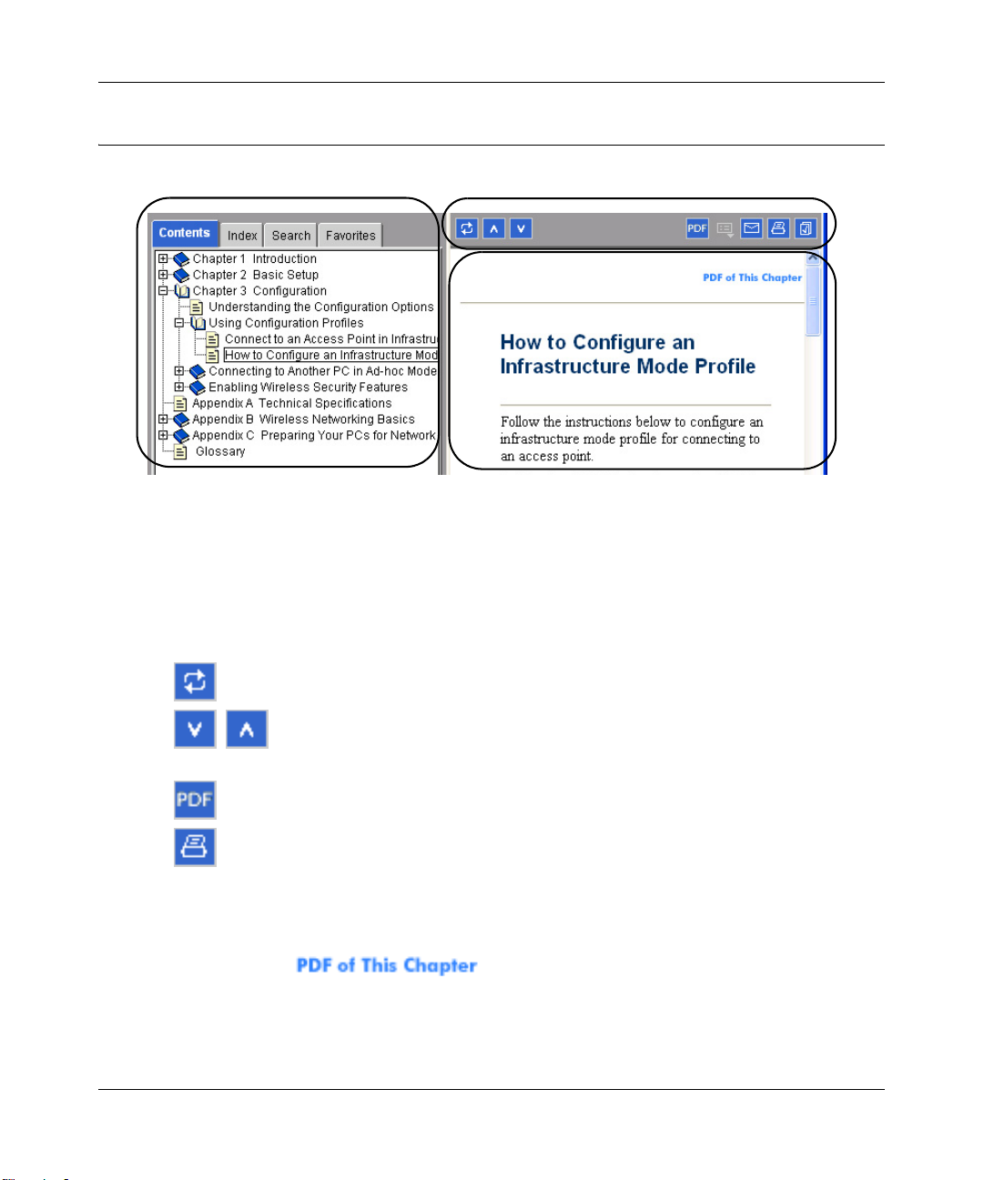
The HTML version of this manual includes these features.
1
2
3
Figure Preface -2: HTML version of this manual
1. Left pane. Use the left pane to view the Contents, Index, Search, and Favorites tabs.
To view the HTML version of the manual, you must have a version 4 or later browser with
JavaScript enabled.
2. Toolbar buttons. Use the toolbar buttons across the top to navigate, print pages, and more.
–The Show in Contents button locates the current topic in the Contents tab.
– Previous/Next buttons display the previous or next topic.
–The PDF button links to a PDF version of the full manual.
–The Print button prints the current topic. Using this button when a step-by-step
procedure is displayed will send the entire procedure to your printer—you do not
have to worry about specifying the correct range of pages.
3. Right pane. Use the right pane to view the contents of the manual. Also, each page of the
manual includes a link at the top right which links to a PDF file
containing just the currently selected chapter of the manual.
About This Guide 1-3
December 2004, 202-10010-02
Page 22

User Manual for the NETGEAR 7200 Series Layer 2 Managed Switch Software
How to Print this Manual
To print this manual you man choose one of the following several options, according to your
needs.
• Printing a “How To” Sequence of Steps in the HTML View. Use the Print button on
the upper right of the toolbar to print the currently displayed topic. Using this button when a
step-by-step procedure is displayed will send the entire procedure to your printer–you do not
have to worry about specifying the correct range of pages.
• Printing a Chapter. Use the link at the top right of any page.
– Click “PDF of This Chapter” link at the top right of any page in the chapter you want to
print. The PDF version of the chapter you were viewing opens in a browser window.
Note: Your computer must have the free Adobe Acrobat reader installed in order to view
and print PDF files. The Acrobat reader is available on the Adobe Web site at
http://www.adobe.com.
– Click the print icon in the upper left of the window.
Tip: If your printer supports printing two pages on a single sheet of paper, you can save
paper and printer ink by selecting this feature.
• Printing the Full Manual. Use the PDF button in the toolbar at the top right of the browser
window.
– Click the PDF button on the upper right of the toolbar. The PDF version of the
chapter you were viewing opens in a browser window.
– Click the print icon in the upper left of the window.
Tip: If your printer supports printing two pages on a single sheet of paper, you can save
paper and printer ink by selecting this feature.
1-4 About This Guide
December 2004, 202-10010-02
Page 23

Chapter 2
Switch Management Overview
This chapter gives an overview of switch management, including the methods you can use to
manage your NETGEAR NETGEAR 7200 Series Layer 2 Managed Switch.
• Management Access Overview
• SNMP Access
• Protocols
Scope
The NETGEAR 7200 Series Layer 2 Managed Switch software has two purposes:
• Assist attached hardware in switching frames, based on Layer 2 or 3 information contained in
the frames.
• Provide a complete switch management portfolio for the network administrator.
Switch Management Overview
Fast Ethernet (FEN) and Gigabit Ethernet (GEN) switching continues to evolve from high-end
backbone applications to desktop switching applications. The price of the technology continues to
decline, while performance and feature sets continue to improve. Devices that are capable of
switching Layers 2, 3, and 4 are increasingly in demand. The NETGEAR 7200 Series Layer 2
Managed Switch provides a flexible solution to these ever-increasing needs.
The NETGEAR 7200 Series Layer 2 Managed Switch provides the network administrator with a
set of comprehensive management functions for managing both the 7200 and the network. The
network administrator has a choice of three easy-to-use management methods:
• Web-based
• VT100 interface
Note: The maximum number of configuration file command lines is 2000 .
Switch Management Overview 2-1
December 2004, 202-10010-02
Page 24

User Manual for the NETGEAR 7200 Series Layer 2 Managed Switch Software
• Simple Network Protocol Management (SNMP)
Each management method enables the network administrator to configure, manage, and control
the managed switch locally or remotely using in-band or out-of-band mechanisms. Management is
standards-based, with configuration parameters and a private MIB providing control for functions
not completely specified in the MIBs.
Table 2-1. Comparing Switch Management Methods
Management Method Advantages Disadvantages
Administration
console
Web browser
or Telnet
SNMP Agent • Communicates with switch functions at the
• Out-of-band access via direct cable
connection means network bottlenecks,
crashes, and downtime do not slow or
prevent access
• No IP address or subnet needed
• Menu or CLI based
• HyperTerminal access to full functionality
(HyperTerminal are built into Microsoft
Windows 95/98/NT/2000 operating
systems)
• Secure – make sure the switch is installed
in a secure area.
• Can be accessed from any location via the
switch’s IP address
• Ideal for configuring the switch remotely
• Compatible with Internet Explorer and
Netscape Navigator Web browsers
• Familiar browser interface
• Graphical data available
• Most visually appealing
• Menu or CLI interfaces available
Management Information Base (MIB) level
• Based on open standards
• Must be near switch or use dial-up
connection
• Not convenient for remote users
• Not graphical
• Security can be compromised (hackers
can attack if they know IP address)
• May encounter lag times on poor
connections
• Displaying graphical objects over a
browser interface may slow navigation
• Requires SNMP manager software
• Least visually appealing of all three
methods
• Limited amount of information
available
• Some settings require calculations
• Security can be compromised (hackers
need only know the community name)
2-2 Switch Management Overview
December 2004, 202-10010-02
Page 25
Chapter 3
Administration Console Telnet Interface
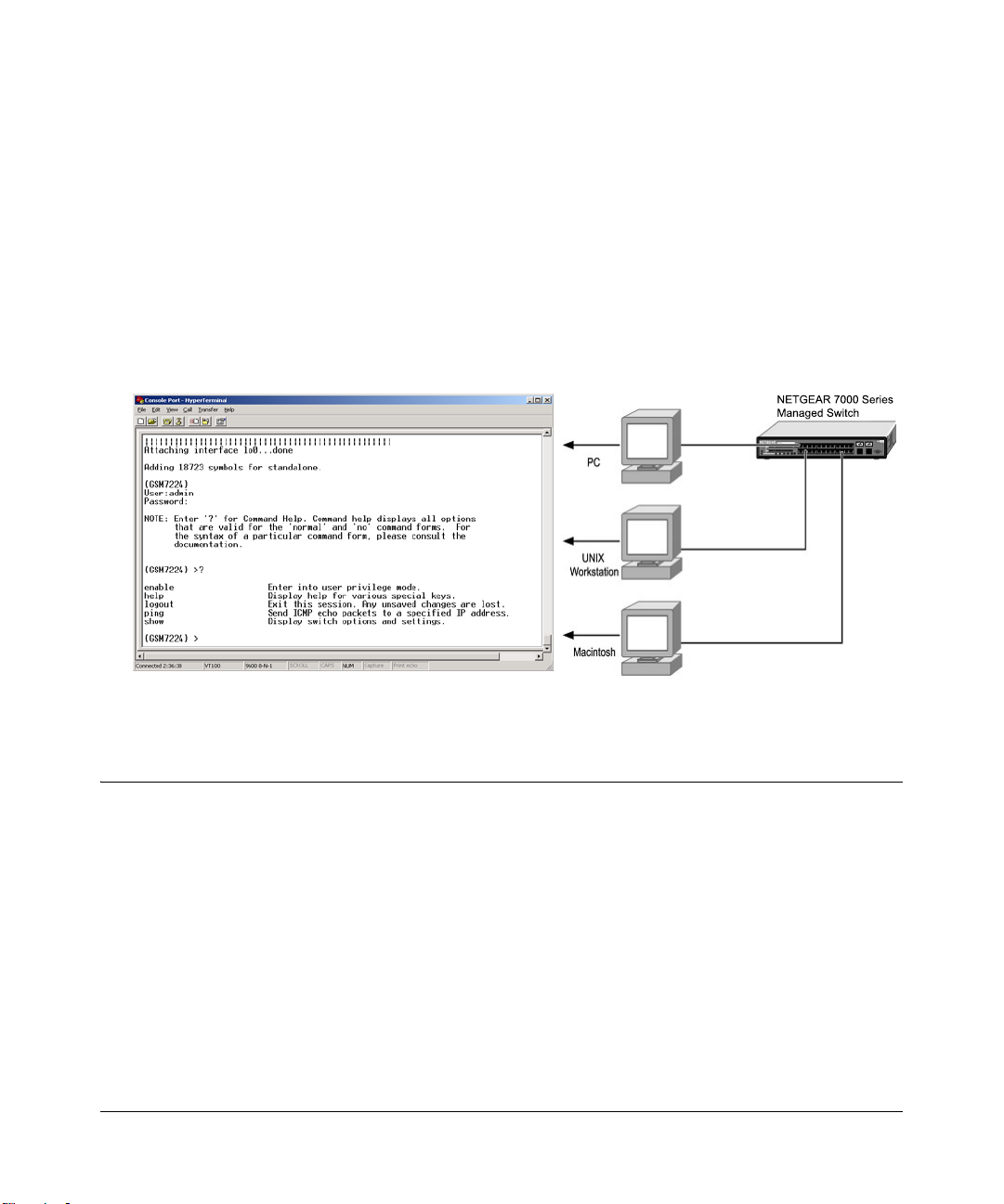
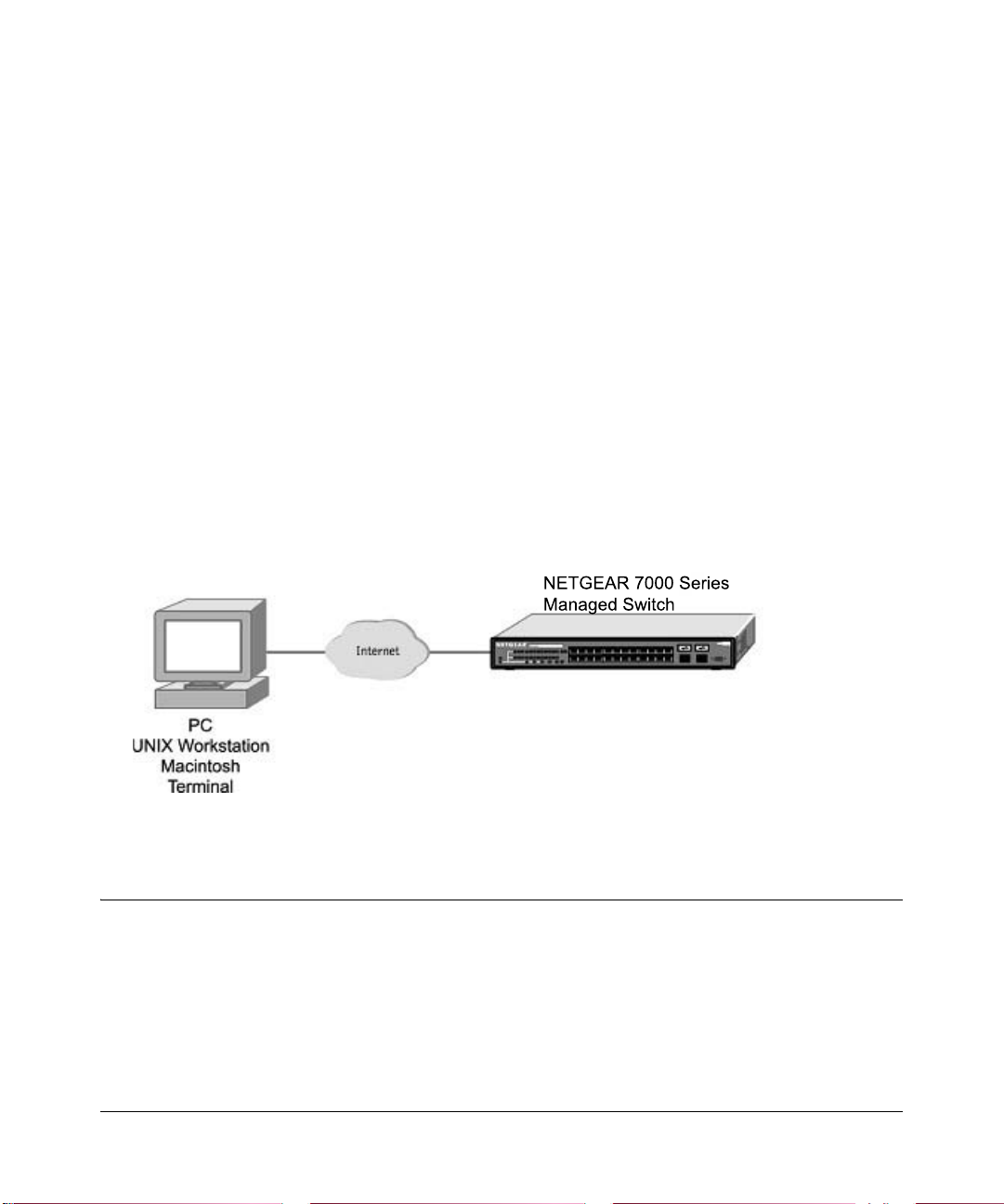
The administration console is an internal, character-oriented, VT-100/ANSI menu-driven user
interface for performing management activities. Using this method, you can view the
administration console from a terminal, PC, Apple Macintosh, or UNIX workstation connected to
the switch’s console port. Figure 3-1 shows an example of this management method.
Figure 3-1: Administration Console Management Method
Set Up Your Switch Using Direct Console Access
The direct access management method is required when you initially set up your switch.
Thereafter, the convenience and additional features of the Web management access method make
it the best method to manage the switch. See “W eb Based Management Overview” on page 4-1 for
more information.
Direct access to the switch console is achiev ed by connecting the switch’s console port to a
VT-100 or compatible terminal or to a PC, Apple Macintosh, or UNIX workstation equipped with
a terminal-emulation program. This connection is made using the null-modem cable supplied with
the switch.
Administration Console Telnet Interface 3-1
December 2004, 202-10010-02
Page 26
User Manual for the NETGEAR 7200 Series Layer 2 Managed Switch Software
Examples of terminal-emulation programs include:
• HyperTerminal, which is included with Microsoft Windows operating systems
• ZTerm for the Apple Macintosh
• TIP for UNIX workstations
This example describes how to set up the connection using a HyperTerminal on a PC, but other
systems follow similar steps.
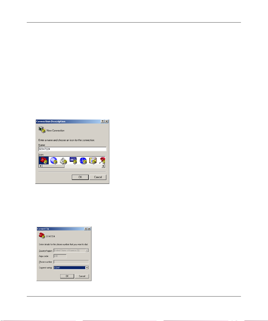
1. Click the Windows S tart button. Select Accessories and then Communications. HyperT erminal
should be one of the options listed in this menu. Select HyperTerminal
2. The following screen will appear. Enter a name for this connection. In the example below, the
name of the connection is GSM7224. Click OK.
Figure 3-2: Connection Description
3.
The following screen will appear . In the bottom, drop down box labeled Connect Using:, click
the arrow and choose the COM port to which the switch will connect. In the example below,
COM1 is the port selected. Click OK.
Figure 3-3: COM Port Selection
3-2 Administration Console Telnet Interface
December 2004, 202-10010-02
Page 27
User Manual for the NETGEAR 7200 Series Layer 2 Managed Switch Software
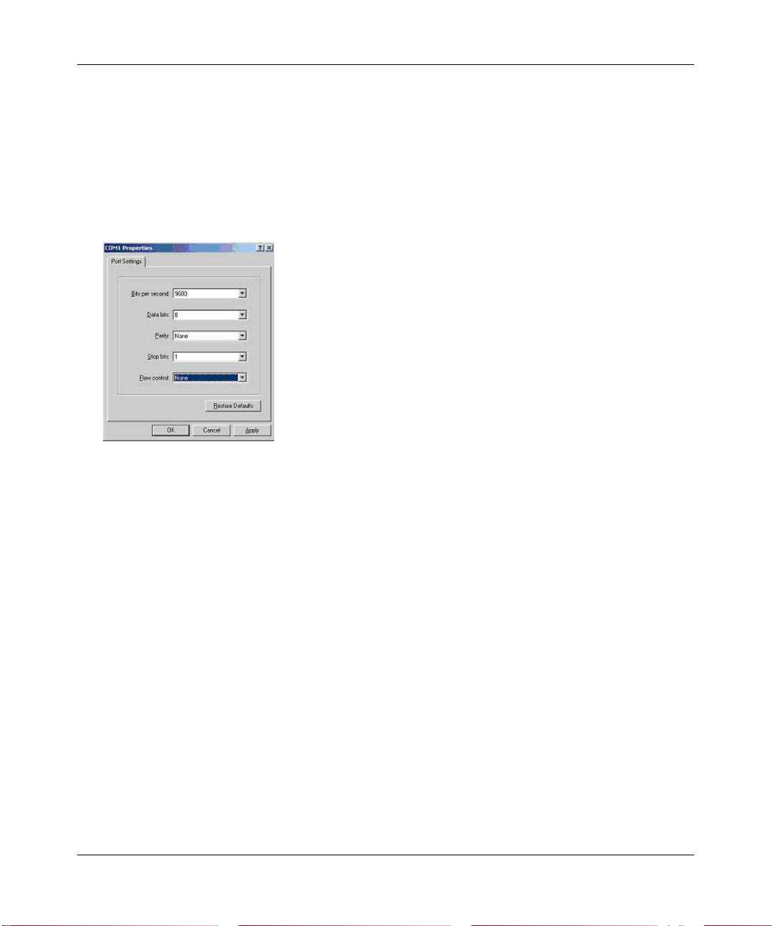
When the following screen appears, make sure that the port setting are as follows:
4.
Baud Rate: 9600
Data Bits: 8
Parity: None
Stop Bits: 1
Flow Control: None
Figure 3-4: Connection Settings
5.
Click OK.
The HyperTerminal window will open and you should be connected to the switch. If you do not
get a welcome screen or a system menu, press the return key.
When attached to the User Interface via a Telnet Session, the following must be set in order to use
the arrow keys: Under the terminal pull down menu, choose Properties and make sure the VT100
Arrows option is turned on.
Administration Console Telnet Interface 3-3
December 2004, 202-10010-02
Page 28

User Manual for the NETGEAR 7200 Series Layer 2 Managed Switch Software
3-4 Administration Console Telnet Interface
December 2004, 202-10010-02
Page 29
Chapter 4
Web-Based Management Interface
Your NETGEAR 7200 Series Layer 2 Managed Switch provides a built-in browser interface that
lets you configure and manage it remotely using a standard Web browser such as Microsoft
Internet Explorer 5.0 or later or Netscape Navigator 6.0 or later.
This interface also allows for system monitoring and management of the switch. The ‘help’ page
covers many of the basic functions and features of the switch and it’s web interface.
When you configure the switch for the first time from the console, you can assign an IP address
and subnet mask to the switch. Thereafter, you can access the switch’ s Web interface directly using
your W eb browser by entering the switch’s IP address into the address bar. In this way, you can use
your Web browser to manage the switch from a central location, just as if you were directly
connected to the switch’s console port. Figu re 4-1 shows this management method.
Figure 4-1: Web Management Method
Web Based Management Overview
The menu options available are: System Management, Switch, Routing, Traffic Management, and
Smart Wizard. There is a help menu in the top of right side of screen; you can click the ‘help’ or
the question mark to read the help menu.
The help menu contains:
• Web-Based Management Introduction to the Web management features.
Web-Based Management Interface 4-1
December 2004, 202-10010-02
Page 30
User Manual for the NETGEAR 7200 Series Layer 2 Managed Switch Software
• Device Management Introduction of the basic icons and management of the device
• Interface Operations Describes Web browser requirements, and common commands
• Product Overview Describes supported SNMP and Web management features
• Summary of Features Feature List
How to Log In to the Managed Switch
The NETGEAR 7200 Series Layer 2 Managed Switch can be configured remotely from Microsoft
Internet Explorer browser version 5.0 or above, or Netscape Navigator web browser version 4.78
or above.
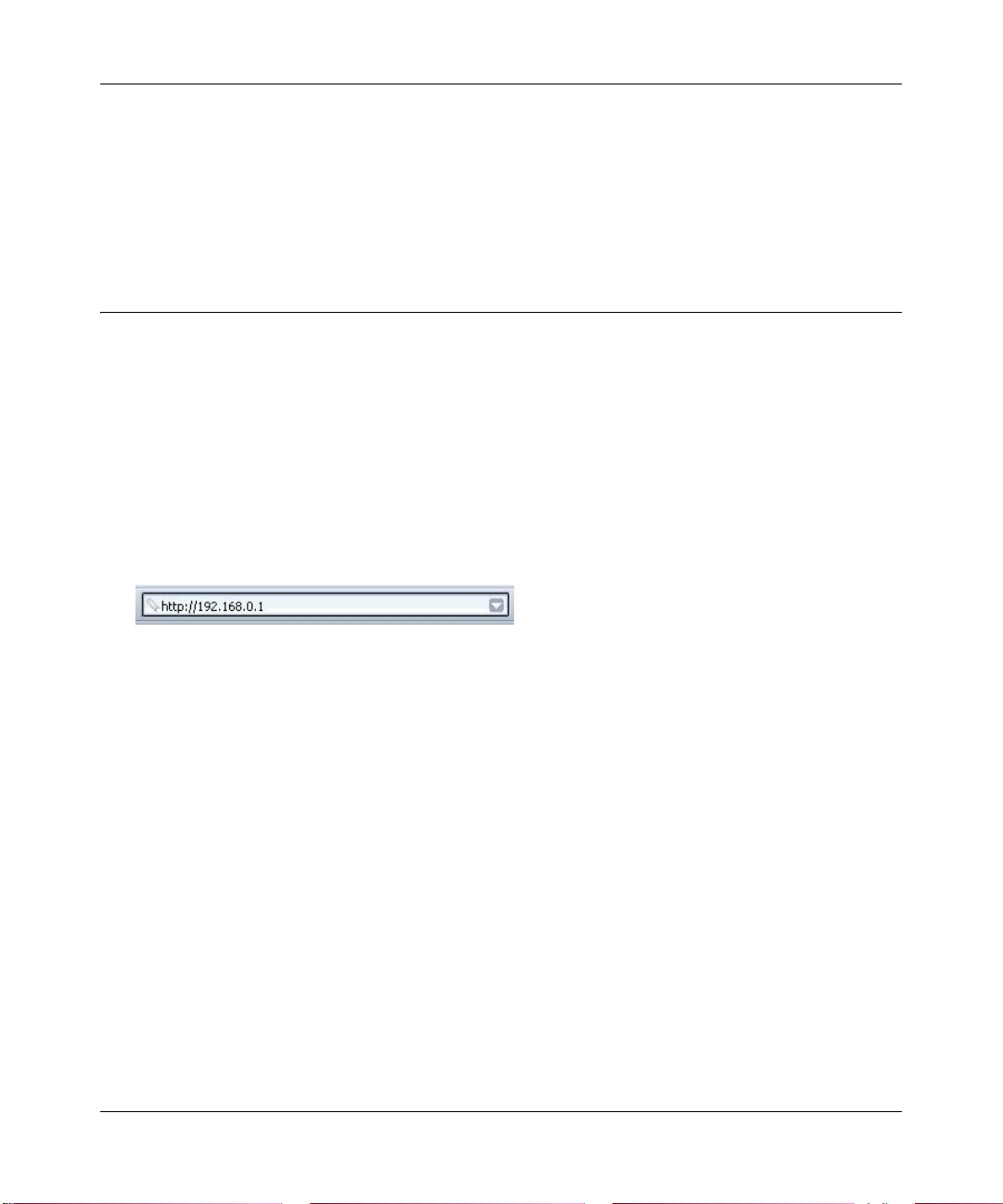
1. Determine the IP address of your managed switch.
2. Open a Web browser such as Internet Explorer or Netscape Navigator.
3. Log in to the managed switch using whatever IP address the unit is currently configured with.
Use the default user name of admin and default of no password, or whatever LAN address and
password you have set up.
.
Figure 4-2: 7200 IP address in browser address bar
A login window opens:
Click the Login link.
4-2 Web-Based Management Interface
December 2004, 202-10010-02
Page 31

User Manual for the NETGEAR 7200 Series Layer 2 Managed Switch Software
A user name and password dialog box opens like this one.
Figure 4-3: User name/password dialog box
4.
Type the default user name of admin and default of no password, or whatever password you
have set up.
Once you have entered your access point name, your Web browser should automatically find
the 7200 Series L2 Switch and display the home page, as shown below.
Web-Based Management Utility Features
This welcome page displays system information, such as:
• System Description
•System Name
• System Location
• System Contact
• IP Address
• System Object ID (OID)
• System Up Time
Web-Based Management Interface 4-3
December 2004, 202-10010-02
Page 32

User Manual for the NETGEAR 7200 Series Layer 2 Managed Switch Software
Interactive Switch Image
This dynamic image shows various real time conditions about the switch, including the status, fan
operation, power, and the connectivity and traffic indication for each port. In addition, using the
popup menus described below, you can directly access a wealth of information by right-clicking
on a port and selecting a menu item from the popup-menu that displays.
Menus
The Web-based interface enables navigation through several menus. The main navigation menu is
on the left of every page and contains the screens that let you access all the commands and
statistics the switch provides.
• Management
• Switch
• Traffic Management
• Smart Wizard
System-Wide Popup Menus
The 7200 Series L2 Switch also provides several popup menus.
You can also access the main navigation menu by right clicking on the image of the switch and
browsing to the menu you want to use.
Port-Specific Popup Menus
The 7200 Series L2 Switch also provides several popup menus for each port.
You can access a port-specific popup menu by right clicking on the port in the image of the switch
and browsing to the menu you want to use.
4-4 Web-Based Management Interface
December 2004, 202-10010-02
Page 33

User Manual for the NETGEAR 7200 Series Layer 2 Managed Switch Software
Chapter 5
Command Line Interface Structure
The Command Line Interface (CLI) syntax, conventions and terminology are described in this
section. Each CLI command is illustrated using the structure outlined below.
CLI Command Format
Commands are followed by values, parameters, or both.
Example 1
network parms <ipaddr> <netmask> [<gateway>]
• network parms is the command name.
• <ipaddr> <netmask> are the required values for the command.
• [<gateway>] is the optional value for the command.
Example 2
snmp-server location <loc>
• snmp-server location is the command name.
• <loc> is the required parameter for the command.
Example 3
clear vlan
• clear vlan is the command name.
Command
The text in bold, non-italic font must be typed exactly as shown.
Command Line Interface Structure 5-1
December 2004, 202-10010-02
Page 34

User Manual for the NETGEAR 7200 Series Layer 2 Managed Switch Software
Parameters
Parameters are order dependent.
The text in bold italics should be replaced with a name or number. To use spaces as part of a name
parameter, enclose it in double quotes like this: “System Name with Spaces”.
Parameters may be mandatory values, optional values, choices, or a combination.
– <parameter>. The <> angle brackets indicate that a mandatory parameter must be entered
in place of the brackets and text inside them.
– [parameter]. The [] square brackets indicate that an optional parameter may be entered in
place of the brackets and text inside them.
– choice1 | choice2. The | indicates that only one of the parameters should be entered.
– The {} curly braces indicate that a parameter must be chosen from the list of choices.
Values
ipaddr This parameter is a valid IP address, made up of four decimal
bytes ranging from 0 to 255. The default for all IP parameters
consists of zeros (that is, 0.0.0.1). The interface IP address of
0.0.0.0 is invalid. In some cases, the IP address can also be
entered as a 32-bit number.
macaddr The MAC address format is six hexadecimal numbers separated
by colons, for example 00:06:29:32:81:40.
areaid Area IDs may be entered in dotted-decimal notation (for example,
0.0.0.1). An area ID of 0.0.0.0 is reserved for the backbone. Area
IDs have the same form as IP addresses, but are distinct from IP
addresses. The IP network number of the sub-netted network may
be used for the area ID.
routerid The value of <router id> must be entered in 4-digit dotted-deci-
mal notation (for example, 0.0.0.1). A router ID of 0.0.0.0 is
invalid.
slot/port This parameter denotes a valid slot number and a valid port num-
ber. For example, 0/1 represents slot number 0 and port number 1.
The <slot/port> field is composed of a valid slot number and a
valid port number separated by a forward slash (/).
5-2 Command Line Interface Structure
December 2004, 202-10010-02
Page 35

User Manual for the NETGEAR 7200 Series Layer 2 Managed Switch Software
logical slot/port This parameter denotes a logical slot number and logical port
number assigned. This is applicable in the case of a port-channel
(LAG). The operator can use the logical slot number and the logical port number to configure the port-channel.
Conventions
Network addresses are used to define a link to a remote host, workstation or network. Network
addresses are shown using the following syntax:
Table 5-1. Network Address Syntax
Address Type Format Range
ipaddr
macaddr
Double quotation marks such as “System Name with Spaces” set off user defined strings. If the
operator wishes to use spaces as part of a name parameter then it must be enclosed in double
quotation marks.
A.B.C.D 0.0.0.0 to 255.255.255.255
(decimal)
YY:YY:YY:YY:YY:YY hexidecimal digit pairs
Empty strings (““) are not valid user defined strings.
Command completion finishes spelling the command when enough letters of a command are typed
to uniquely identify the command word. The command may be executed by typing <enter>
(command abbreviation) or the command word may be completed by typing the <tab> or <space
bar> (command completion).
The value 'Err' designates that the requested value was not internally accessible. This should never
happen and indicates that there is a case in the software that is not handled correctly.
The value of '-----' designates that the value is unknown.
Command Line Interface Structure 5-3
December 2004, 202-10010-02
Page 36

User Manual for the NETGEAR 7200 Series Layer 2 Managed Switch Software
Annotations
The CLI allows the user to type single-line annotations at the command prompt for use when
writing test or configuration scripts and for better readability . The exclamation point (‘!’) character
flags the beginning of a comment. The comment flag character can begin a word anywhere on the
command line and all input following this character is ignored. Any command line that begins
with the character ‘!’ is recognized as a comment line and ignored by the parser.
Some examples are provided below:
! Script file for displaying the ip interface
! Display information about interfaces
show ip interface 0/1 !Displays the information about the first interface
! Display information about the next interface
show ip interface 0/2
! End of the script file
5-4 Command Line Interface Structure
December 2004, 202-10010-02
Page 37

User Manual for the NETGEAR 7200 Series Layer 2 Managed Switch Software
Chapter 6
Quick Start up
The CLI Quick Start up details procedures to quickly become acquainted with the 7200 Series L2
Switch.
Quick Starting the Switch
1. Read the device Installation Guide for the connectivity procedure. In-band connectivity allows
access to the 7200 Series L2 Switch locally or from a remote workstation. The device must be
configured with IP information (IP address, subnet mask, and default gateway).
2. Turn the Power ON.
3. Allow the device to load the software until the login prompt appears. The device initial state is
called the default mode.
4. When the prompt asks for operator login, execute the following steps:
• Type the word admin in the login area. Since a number of the Quick Setup commands
require administrator account rights, NETGEAR suggests logging into an administrator
account.
• Do not enter a password because there is no password in the default mode.
• Press the enter key two times.
• The CLI User EXEC prompt will be displayed.
• Use “enable” to switch to the Privileged EXEC mode from User EXEC.
• Use “configure” to switch to the Global Config mode from Privileged EXEC.
• Use “exit” to return to the previous mode.
Quick Start up 6-1
December 2004, 202-10010-02
Page 38

User Manual for the NETGEAR 7200 Series Layer 2 Managed Switch Software
System Info and System Setup
Quick Start up Software Version Information
Table 6-1. Quick Start up Software Version Information
Command Details
show hardware
(in Privileged EXEC)
Quick Start up Physical Port Data
Table 6-2. Quick Start up Physical Port Data
Command Details
show port all
(in Privileged EXEC)
Allows the user to see the software version the device contains
Software Version - current release software loaded in the switch
Displays the Ports
slot/port
Type - Indicates if the port is a special type of port
Admin Mode - Selects the Port Control Administration State
Physical Mode - Selects the desired port speed and duplex mode
Physical Status - Indicates the port speed and duplex mode
Link Status - Indicates whether the link is up or down
Link Trap - Determines whether or not to send a trap when link status
changes
LACP Mode - Displays whether LACP is enabled or disabled on this
port.
6-2 Quick Start up
December 2004, 202-10010-02
Page 39

User Manual for the NETGEAR 7200 Series Layer 2 Managed Switch Software
Quick Start up User Account Management
Table 6-3. Quick Start up User Account Management
Command Details
show users
(in Privileged EXEC)
show loginsession
(in User EXEC)
users passwd <username>
(in Global Config)
copy system:running-config
nvram:startup-config
(in Privileged EXEC)
logout
(in User EXEC and Privileged
EXEC)
Displays all of the users that are allowed to access the switch
Access Mode - Shows whether the user is able to change
parameters on the switch (Read/Write) or is only able to view
then (Read Only).
As a factory default, admin has Read/Write access and guest
has Read Only access. There can only be one Read/Write user
and up to 5 Read Only users.
Displays all of the login session information
Allows the user to set passwords or change passwords needed
to login
A prompt will appear after the command is entered requesting
the users old password. In the absence of an old password
leave the area blank. The operator must press enter to execute
the command.
The system then prompts the user for a new password then a
prompt to confirm the new password. If the new password and
the confirmed password match a message will be displayed.
User password should not be more than eight characters in
length.
This will save passwords and all other changes to the device.
If you do not save config, all configurations will be lost when a
power cycle is performed on the switch or when the switch is
reset
Logs the user out of the switch
Quick Start up IP Address
To view the network parameters the operator can access the device by the following three
methods.
• Simple Network Management Protocol - SNMP
•Telnet
Quick Start up 6-3
December 2004, 202-10010-02
Page 40

User Manual for the NETGEAR 7200 Series Layer 2 Managed Switch Software
• Web Browser
Note: The user should do a copy system:running-config nvram:startup-config after
configuring the network parameters so that the configurations are not lost
Table 6-4. Quick Start up IP Address
Command Details
show network
(in User EXEC)
network parms
(in Privileged EXEC)
Displays the Network Configurations
IP Address - IP Address of the interface
Default IP is 0.0.0.0
Subnet Mask - IP Subnet Mask for the interface
Default is 0.0.0.0
Default Gateway - The default Gateway for this interf ace
Default value is 0.0.0.0
Burned in MAC Address - The Burned in MAC Address used for inband connectivity
Network Configurations Protocol Current - Indicates which network
protocol is being used
Default is none
Management VLAN Id - Specifies VLAN id
Web Mode - Indicates whether HTTP/Web is enabled.
Java Mode - Indicates whether java mode is enabled.
network parms <ipaddr> <netmask> [<gateway>]
IP Address range from 0.0.0.0 to 255.255.255.255
Subnet Mask range from 0.0.0.0 to 255.255.255.255
Gateway Address range from 0.0.0.0 to 255.255.255.255
Note: The IP address assigned to network in the above table will not be routable. If access to
management CPU via the routable interface is desired, use the
ip command.
6-4 Quick Start up
December 2004, 202-10010-02
Page 41

User Manual for the NETGEAR 7200 Series Layer 2 Managed Switch Software
Quick Start up Uploading from Switch to Out-of-Band PC (Only XMODEM)
Table 6-5. Quick Start up Uploading from Switch to Out-of-Band PC (XMODEM)
Command Details
copy {
nvram:startup-config |
nvram:errorlog |
nvram:msglog |
nvram:traplog} <url>
The types are:
config - configuration file
errorlog - error log
system trace - system trace
traplog - trap log
The URL must be specified as:
xmodem:filepath/fileName
This starts the upload and also displays the mode of
uploading and the type of upload it is and confirms the
upload is taking place.
For example:
If the user is using HyperT e rminal, the user must
specify where the file is going to be received by the
PC.
Quick Start up 6-5
December 2004, 202-10010-02
Page 42

User Manual for the NETGEAR 7200 Series Layer 2 Managed Switch Software
Quick Start up Downloading from Out-of-Band PC to Switch (Only XMODEM)
T able 6-6. Quick Start up Downloading from Out-of-Band PC to Switch (Only XMODEM)
Command Details
copy <url> {nvram:startup-config |
system:image}
Sets the download datatype to be an image or
config file.
The URL must be specified as:
xmodem:filepath/fileName
For example:
If the user is using HyperTerminal, the user
must specify which file is to be sent to the
switch.
The Switch will restart automatically once the
code has been downloaded.
Quick Start up Downloading from TFTP Server
Before starting a TFTP server download, the operator must complete the Quick Start up for the IP
Address.
Table 6-7. Quick Start up Downloading from TFTP Server
Command Details
copy <url> {nvram:startup-config |
system:image}
Sets the download datatype to be an image
or config file.
The URL must be specified as:
tftp://ipAddr/filepath/fileName.
The nvram:startup-config option downloads
the config file using tftp and system:image
option downloads the code file.
6-6 Quick Start up
December 2004, 202-10010-02
Page 43

User Manual for the NETGEAR 7200 Series Layer 2 Managed Switch Software
Quick Start up Factory Defaults
Table 6-8. Quick Start up Fac tory Defaults
Command Details
clear config Enter yes when the prompt pops up to clear all the configurations
made to the switch.
copy system:running-config
nvram:startup-config
reload OR Cold Boot the Switch Enter yes when the prompt pops up that asks if you want to reset
Enter yes when the prompt pops up that asks if you want to save
the configurations made to the switch.
the system.
This is the users choice either reset the switch or cold boot the
switch, both work effectivel y.
Quick Start up 6-7
December 2004, 202-10010-02
Page 44

User Manual for the NETGEAR 7200 Series Layer 2 Managed Switch Software
6-8 Quick Start up
December 2004, 202-10010-02
Page 45

User Manual for the NETGEAR 7200 Series Layer 2 Managed Switch Software
Chapter 7
Mode-based CLI
The CLI groups all the commands in appropriate modes according to the nature of the command.
A sample of the CLI command modes are described below. Each of the command modes support
specific 7200 Series L2 Switch commands.
• User Exec Mode
• Privileged Exec Mode
• Global Config Mode
•Vlan Mode
• Interface Config Mode
• Line Config Mode
The Command Mode table captures the command modes, the prompts visible in that mode and the
exit method from that mode.
Table 7-1. Command Mode
Command Mode Access Method Prompt
User Exec Mode This is the first level of
access. Perform basic
tasks and list system
information.
Privileged Exec Mode From the User Exec
Mode, enter the
command.
VLAN Mode From the Privileged
User Exec mode, enter
vlan database
the
command.
Mode-based CLI 7-1
enable
December 2004, 202-10010-02
Switch> Enter Logout command
Switch# To exit this mode, enter
Switch (Vlan) # To exit to the Privileged
Exit or Access Next
Mode
exit or press Ctrl-Z.
Exec mode, enter the
exit command, or press
Ctrl-Z to switch to user
exec mode.
Page 46

User Manual for the NETGEAR 7200 Series Layer 2 Managed Switch Software
Table 7-1. Command Mode (continued)
Command Mode Access Method Prompt
Global Config Mode From the Privileged
Exec mode, enter the
Switch (Config)# To exit to the Privileged
configure command.
Interface Config Mode From the Global
Configuration mode,
enter the
interface
Switch (Interface-”if
number”)#
config <slot/port>
command.
Line Config Mode From the Global
Configuration mode,
enter the
command.
lineconfig
Switch (line) # To exit to the Global
Exit or Access Next
Mode
Exec mode, enter the
exit command, or press
Ctrl-Z to switch to user
exec mode.
To exit to the Global
Config mode enter exit.
To return to user EXEC
mode enter ctrl-Z.
Config mode enter exit.
To return to User Exec
mode enter ctrl-Z.
Mode-based Topology
The CLI tree is built on a mode concept where the commands are available according to the
interface. Some of the modes are depicted in the mode-based CLI Figure 1.
7-2 Mode-based CLI
December 2004, 202-10010-02
Page 47

User Manual for the NETGEAR 7200 Series Layer 2 Managed Switch Software
ROOT
User Exec
User Exec commands
are also accessible in
Privileg ed Exec
mode.
VLAN
Line Config
Enable
Passwd
Correct
?
Privileged
Yes
Global Config
No Return to Exec
prompt
Interface
Circuit Config
FIGURE 1. Mode-based CLI
Access to all commands in the Privileged Exec mode and below are restricted through a password.
Mode-based CLI 7-3
December 2004, 202-10010-02
Page 48

User Manual for the NETGEAR 7200 Series Layer 2 Managed Switch Software
Mode-based Command Hierarchy
The CLI is divided into various modes. The Commands in one mode are not available until the
operator switches to that particular mode, with the exception of the User Exec mode commands.
The User Exec mode commands may also be executed in the Privileged Exec mode.
The commands available to the operator at any point in time depend upon the mode. Entering a
question mark (?) at the CLI prompt, displays a list of the available commands and descriptions of
the commands.
The CLI provides the following modes:
User Exec Mode When the operator logs into the CLI, the User Exec mode is the
initial mode. The User Exec mode contains a limited set of commands. The command prompt shown at this level is:
Command Prompt: $(Exec)>
Privileged Exec Mode To have access to the full suite of commands, the operator must
enter the Privileged Exec mode. The Privileged Exec mode
requires password authentication. From Privileged Exec mode,
the operator can issue any Exec command or enter the Global
Configuration mode. The command prompt shown at this level is:
Command Prompt: $(Exec)#
Global Config Mode This mode permits the operator to make modifications to the run-
ning configuration. General setup commands are grouped in this
mode. From the Global Configuration mode, the operator can
enter the System Configuration mode, the Physical Port config,
the Interface Configuration mode, or the Protocol Specific modes
specified below. The command prompt at this level is:
Command Prompt: $(Config)#
From the Global Config mode, the operator may enter the following config modes:
VLAN Mode This mode groups all the commands pertaining to VLANs. The
command prompt shown at this level is:
Command Prompt: $(VLAN)#
Interface Config Mode Many features are enabled for a particular interface. The Interface
commands enable or modify the operation of an interface.
In this mode, a physical port is set up for a specific logical con-
nection operation. The Interface Config mode provides access to
7-4 Mode-based CLI
December 2004, 202-10010-02
Page 49

User Manual for the NETGEAR 7200 Series Layer 2 Managed Switch Software
the router interface configuration commands. The command
prompt at this level is:
Command Prompt: $(Interface <slot/port>)#
The resulting prompt for the interface configuration command
entered in the Global Configuration mode is shown below:
$(Config)# interface 2/1
$(Interface 2/1)#
Line Config Mode This mode allows the operator to configure the console interface.
The operator may configure the interface from the directly connected console or the virtual terminal used with Telnet. The command prompt at this level is:
Command Prompt: $(Line)#
Flow of Operation
This section captures the flow of operation for the CLI:
1. The operator logs into the CLI session and enters the User Exec mode. In the User Exec mode
the $(exec)> prompt is displayed on the screen.
The parsing process is initiated whenever the operator types a command and presses <ENTER>.
The command tree is searched for the command of interest. If the command is not found, the
output message indicates where the offending entry begins. For instance, command node A has the
command
brief” then the output message would be $(exec)> show arpp brief^. $%Invalid input detected at '^'
marker.
“show arp brief” but the operator attempts to execute the command “show arpp
If the operator has given an invalid input parameter in the command, then the message
conveys to the operator an invalid input was detected. The layout of the output is depicted below:
(exec) #show arpp brief
^
%Invalid input detected at ‘^’ marker.
FIGURE 2. Syntax Error Message
Mode-based CLI 7-5
December 2004, 202-10010-02
Page 50

User Manual for the NETGEAR 7200 Series Layer 2 Managed Switch Software
After all the mandatory parameters are entered, any additional parameters entered are treated as
optional parameters. If any of the parameters are not recognized a syntax error message will be
displayed.
2. After the command is successfully parsed and validated, the control of execution goes to the
corresponding CLI callback function.
3. For mandatory parameters, the command tree extends till the mandatory parameters make the
leaf of the branch. The callback function is only invoked when all the mandatory parameters
are provided. For optional parameters, the command tree extends till the mandatory
parameters and the optional parameters make the leaf of the branch. However, the call back
function is associated with the node where the mandatory parameters are fetched. The call
back function then takes care of the optional parameters.
4. Once the control has reached the callback function, the callback function has complete
information about the parameters entered by the operator.
“No” Form of a Command
“No” is a specific form of an existing command and does not represent a new or distinct command.
Only the configuration commands are available in the “no” form. The behavior and the support
details of the “no” form is captured as part of the mapping sheets. The mapping sheets are
contained in the Appendix A, “IS CLI Mapping section.
Support for “No” Form
Almost every configuration command has a “no” form. In general, use the no form to reverse the
action of a command or reset a value back to the default. For example, the “no shutdown interface’
configuration command reverses the shutdown of an interface. Use the command without the
keyword no to re-enable a disabled feature or to enable a feature that is disabled by default.
Behavior of Command Help (“?”)
The “no” form is treated as a specific form of an existing command and does not represent a new
or distinct command. This implies that the behavior of the “?” and help text is the same for the
“no” form:
• The help message is the same for all forms of the command. The help string may be
augmented with details about the “no” form behavior.
7-6 Mode-based CLI
December 2004, 202-10010-02
Page 51

User Manual for the NETGEAR 7200 Series Layer 2 Managed Switch Software
• For the (no config interface?) and (no config inte?) cases of the “?”, the options displayed are
identical to the case when the “no” token is not specified.
Mode-based CLI 7-7
December 2004, 202-10010-02
Page 52

User Manual for the NETGEAR 7200 Series Layer 2 Managed Switch Software
7-8 Mode-based CLI
December 2004, 202-10010-02
Page 53

User Manual for the NETGEAR 7200 Series Layer 2 Managed Switch Software
Chapter 8
Switching Commands
This chapter provides detailed explanation of the Switching commands. The commands are
divided into five functional groups:
• Show commands display switch settings, statistics, and other information.
• Configuration Commands configure features and options of the switch. For every
configuration command there is a show command that displays the configuration setting.
• Copy commands transfers or saves configuration and informational files to and from the
switch.
• Clear commands clear some or all of the settings to factory defaults.
This chapter includes the following configuration types:
• System information and statistics commands
• Management commands
• Device configuration commands
• User account management commands
• Security commands
• System utilities
System Information and Statistics Commands
show arp switch
This command displays connectivity between the switch and other devices. The Address
Resolution Protocol (ARP) cache identifies the MAC addresses of the IP stations communicating
with the switch.
Format
Mode Privileged EXEC
MAC Address A unicast MAC address for which the switch has forwarding and/
Switching Commands 8-1
show arp switch
or filtering information. The format is 6 two-digit hexadecimal
December 2004, 202-10010-02
Page 54

User Manual for the NETGEAR 7200 Series Layer 2 Managed Switch Software
numbers that are separated by colons, for example
01:23:45:67:89:AB
IP Address The IP address assigned to each interface.
slot/port Valid slot number and a valid port number.
show eventlog
This command displays the event log, which contains error messages from the system. The event
log is not cleared on a system reset.
Format
show eventlog
Mode Privileged EXEC
File The file in which the event originated.
Line The line number of the event
Task Id The task ID of the event.
Code The event code.
Time The time this event occurred.
Note: Event log information is retained across a switch reset.
show hardware
This command displays inventory information for the switch.
Format
Mode
Description Text used to identify the product name of this switch.
Burned in MAC Address Universally assigned network address.
Software Version The release.version.revision number of the code currently run-
show hardware
Privileged EXEC
ning on the switch.
show interface
This command displays a summary of statistics for a specific port or a count of all CPU traffic
based upon the argument.
Format
8-2 Switching Commands
show interface {<slot/port> | switchport}
December 2004, 202-10010-02
Page 55

User Manual for the NETGEAR 7200 Series Layer 2 Managed Switch Software
Mode Privileged EXEC
The display parameters when the argument is ' <slot/port>' is as follows:
Packets Received Without Error The total number of packets (including broadcast pack-
ets and multicast packets) received by the processor.
Packets Received With Error The number of inbound packets that contained errors pre-
venting them from being deliverable to a higher-layer protocol.
Broadcast Packets Received The total number of packets received that were directed to
the broadcast address. Note that this does not include multicast
packets.
Packets Transmitted Without Error The total number of packets transmitted out of the
interface.
Transmit Packets Errors The number of outbound packets that could not be transmitted
because of errors.
Collisions Frames The best estimate of the total number of collisions on this Ether-
net segment.
Time Since Counters Last Cleared The elapsed time, in days, hours, minutes, and sec-
onds since the statistics for this port were last cleared.
The display parameters when the argument is 'switchport' is as follows:
Packets Received Without Error The total number of packets (including broadcast pack-
ets and multicast packets) received by the processor.
Broadcast Packets Received The total number of packets received that were directed to
the broadcast address. Note that this does not include multicast
packets.
Packets Received With Error The number of inbound packets that contained errors pre-
venting them from being deliverable to a higher-layer protocol.
Packets Transmitted Without Error The total number of packets transmitted out of the
interface.
Broadcast Packets Transmitted The total number of packets that higher-level protocols
requested to be transmitted to the Broadcast address, including
those that were discarded or not sent.
Transmit Packet Errors The number of outbound packets that could not be transmitted
because of errors.
Switching Commands 8-3
December 2004, 202-10010-02
Page 56

User Manual for the NETGEAR 7200 Series Layer 2 Managed Switch Software
Address Entries Currently In Use The total number of Forwarding Database Address
Table entries now active on the switch, including learned and
static entries.
VLAN Entries Currently In Use The number of VLAN entries presently occupying the
VLAN table.
Time Since Counters Last Cleared The elapsed time, in days, hours, minutes, and sec-
onds since the statistics for this switch were last cleared.
show interface ethernet
This command displays detailed statistics for a specific port or for all CPU traffic based upon the
argument.
Format show interface ethernet {<slot/port> | switchport}
Mode
Privileged EXEC
The display parameters when the argument is ' <slot/port>' is as follows:
Packets Received Octets Received - The total number of octets of data (including
those in bad packets) received on the network (excluding framing
bits but including FCS octets). This object can be used as a reasonable estimate of ethernet utilization. If greater precision is
desired, the etherStatsPkts and etherStatsOctets objects should be
sampled before and after a common interval. ----- The result of
this equation is the value Utilization which is the percent utilization of the ethernet segment on a scale of 0 to 100 percent.
Packets Received < 64 Octets - The total number of packets
(including bad packets) received that were < 64 octets in length
(excluding framing bits but including FCS octets).
Packets Received 64 Octets - The total number of packets
(including bad packets) received that were 64 octets in length
(excluding framing bits but including FCS octets).
Packets Received 65-127 Octets - The total number of packets
(including bad packets) received that were between 65 and 127
octets in length inclusive (excluding framing bits but including
FCS octets).
Packets Received 128-255 Octets - The total number of packets
(including bad packets) received that were between 128 and 255
8-4 Switching Commands
December 2004, 202-10010-02
Page 57

User Manual for the NETGEAR 7200 Series Layer 2 Managed Switch Software
octets in length inclusive (excluding framing bits but including
FCS octets).
Packets Received 256-511 Octets - The total number of packets
(including bad packets) received that were between 256 and 511
octets in length inclusive (excluding framing bits but including
FCS octets).
Packets Received 512-1023 Octets - The total number of packets (including bad packets) received that were between 512 and
1023 octets in length inclusive (excluding framing bits but
including FCS octets).
Packets Received 1024-1518 Octets - The total number of packets (including bad packets) received that were between 1024 and
1518 octets in length inclusive (excluding framing bits but
including FCS octets).
Packets Received 1519-1522 Octets - The total number of packets (including bad packets) received that were between 1519 and
1522 octets in length inclusive (excluding framing bits but
including FCS octets).
Packets Received > 1522 Octets - The total number of packets
received that were longer than 1522 octets (excluding framing
bits, but including FCS octets) and were otherwise well formed.
Packets Received Successfully
Total - The total number of packets received that were without
errors.
Unicast Packets Received - The number of subnetwork-unicast
packets delivered to a higher-layer protocol.
Multicast Packets Received - The total number of good packets
received that were directed to a multicast address. Note that this
number does not include packets directed to the broadcast
address.
Broadcast Packets Received - The total number of good packets
received that were directed to the broadcast address. Note that
this does not include multicast packets.
Packets Received with MAC Errors
Total - The total number of inbound packets that contained errors
preventing them from being deliverable to a higher-layer protocol.
Switching Commands 8-5
December 2004, 202-10010-02
Page 58

User Manual for the NETGEAR 7200 Series Layer 2 Managed Switch Software
Jabbers Received - The total number of packets received that
were longer than 1518 octets (excluding framing bits, but including FCS octets), and had either a bad Frame Check Sequence
(FCS) with an integral number of octets (FCS Error) or a bad FCS
with a non-integral number of octets (Alignment Error). Note that
this definition of jabber is different than the definition in IEEE-
802.3 section 8.2.1.5 (10BASE5) and section 10.3.1.4
(10BASE2). These documents define jabber as the condition
where any packet exceeds 20 ms. The allowed range to detect
jabber is between 20 ms and 150 ms.
Fragments/Undersize Received - The total number of packets
received that were less than 64 octets in length (excluding framing bits but including FCS octets).
Alignment Errors - The total number of packets received that
had a length (excluding framing bits, but including FCS octets) of
between 64 and 1518 octets, inclusive, but had a bad Frame
Check Sequence (FCS) with a non-integral number of octets.
Rx FCS Errors - The total number of packets received that had a
length (excluding framing bits, but including FCS octets) of
between 64 and 1518 octets, inclusive, but had a bad Frame
Check Sequence (FCS) with an integral number of octets
Overruns - The total number of frames discarded as this port was
overloaded with incoming packets, and could not keep up with
the inflow .
Received Packets not forwarded
Total - A count of valid frames received which were discarded
(i.e. filtered) by the forwarding process.
Local Traffic Frames - The total number of frames dropped in
the forwarding process because the destination address was
located off of this port.
802.3x Pause Frames Received - A count of MAC Control
frames received on this interface with an opcode indicating the
PAUSE operation. This counter does not increment when the
interface is operating in half-duplex mode.
Unacceptable Frame Type - The number of frames discarded
from this port due to being an unacceptable frame type.
VLAN Membership Mismatch - The number of frames discarded on this port due to ingress filtering.
8-6 Switching Commands
December 2004, 202-10010-02
Page 59

User Manual for the NETGEAR 7200 Series Layer 2 Managed Switch Software
VLAN Viable Discards - The number of frames discarded on
this port when a lookup on a particular VLAN occurs while that
entry in the VLAN table is being modified, or if the VLAN has
not been configured.
Multicast Tree Viable Discards - The number of frames discarded when a lookup in the multicast tree for a VLAN occurs
while that tree is being modified.
Reserved Address Discards - The number of frames discarded
that are destined to an IEEE 802.1 reserved address and are not
supported by the system.
Broadcast Storm Recovery - The number of frames discarded
that are destined for FF:FF:FF:FF:FF:FF when Broadcast Storm
Recovery is enabled.
CFI Discards - The number of frames discarded that have CFI
bit set and the addresses in RIF are in non-canonical format.
Upstream Threshold - The number of frames discarded due to
lack of cell descriptors available for that packet's priority level.
Packets Transmitted Octets
Total Bytes - The total number of octets of data (including those
in bad packets) received on the network (excluding framing bits
but including FCS octets). This object can be used as a reasonable
estimate of ethernet utilization. If greater precision is desired, the
etherStatsPkts and etherStatsOctets objects should be sampled
before and after a common interval. -----
Packets Transmitted 64 Octets - The total number of packets
(including bad packets) received that were 64 octets in length
(excluding framing bits but including FCS octets).
Packets Transmitted 65-127 Octets - The total number of packets (including bad packets) received that were between 65 and
127 octets in length inclusive (excluding framing bits but including FCS octets).
Packets Transmitted 128-255 Octets - The total number of
packets (including bad packets) received that were between 128
and 255 octets in length inclusive (excluding framing bits but
including FCS octets).
Packets Transmitted 256-511 Octets - The total number of
packets (including bad packets) received that were between 256
Switching Commands 8-7
December 2004, 202-10010-02
Page 60

User Manual for the NETGEAR 7200 Series Layer 2 Managed Switch Software
and 511 octets in length inclusive (excluding framing bits but
including FCS octets).
Packets Transmitted 512-1023 Octets - The total number of
packets (including bad packets) received that were between 512
and 1023 octets in length inclusive (excluding framing bits but
including FCS octets).
Packets Transmitted 1024-1518 Octets - The total number of
packets (including bad packets) received that were between 1024
and 1518 octets in length inclusive (excluding framing bits but
including FCS octets).
Packets Transmitted 1519-1522 Octets - The total number of
packets (including bad packets) received that were between 1519
and 1522 octets in length inclusive (excluding framing bits but
including FCS octets).
Max Info - The maximum size of the Info (non-MAC) field that
this port will receive or transmit.
Packets Transmitted Successfully
Total - The number of frames that have been transmitted by this
port to its segment.
Unicast Packets Transmitted - The total number of packets that
higher-level protocols requested be transmitted to a subnetworkunicast address, including those that were discarded or not sent.
Multicast Packets Transmitted - The total number of packets
that higher-level protocols requested be transmitted to a Multicast
address, including those that were discarded or not sent.
Broadcast Packets Transmitted - The total number of packets
that higher-level protocols requested be transmitted to the Broadcast address, including those that were discarded or not sent.
Transmit Errors
Total Errors - The sum of Single, Multiple, and Excessive Collisions.
Tx FCS Errors - The total number of packets transmitted that
had a length (excluding framing bits, but including FCS octets) of
between 64 and 1518 octets, inclusive, but had a bad Frame
Check Sequence (FCS) with an integral number of octets
Oversized - The total number of frames that exceeded the max
permitted frame size. This counter has a max increment rate of
815 counts per sec. at 10 Mb/s.
8-8 Switching Commands
December 2004, 202-10010-02
Page 61

User Manual for the NETGEAR 7200 Series Layer 2 Managed Switch Software
Transmit Discards
Protocol Statistics
Underrun Errors - The total number of frames discarded
because the transmit FIFO buffer became empty during frame
transmission.
Total Discards - The sum of single collision frames discarded,
multiple collision frames discarded, and excessive frames discarded.
Single Collision Frames - A count of the number of successfully
transmitted frames on a particular interface for which transmission is inhibited by exactly one collision.
Multiple Collision Frames - A count of the number of successfully transmitted frames on a particular interface for which transmission is inhibited by more than one collision.
Excessive Collisions - A count of frames for which transmission
on a particular interface fails due to excessive collisions.
Port Membership - The number of frames discarded on egress
for this port due to egress filtering being enabled.
VLAN Viable Discards - The number of frames discarded on
this port when a lookup on a particular VLAN occurs while that
entry in the VLAN table is being modified, or if the VLAN has
not been configured.
BPDU's received - The count of BPDU's (Bridge Protocol Data
Units) received in the spanning tree layer.
BPDU's Transmitted - The count of BPDU's (Bridge Protocol
Data Units) transmitted from the spanning tree layer.
802.3x Pause Frames Received - A count of MAC Control
frames received on this interface with an opcode indicating the
PAUSE operation. This counter does not increment when the
interface is operating in half-duplex mode.
GVRP PDU's Received - The count of GVRP PDU's received in
the GARP layer.
GVRP PDU's T ransmitted - The count of GVRP PDU's transmitted from the GARP layer.
GVRP Failed Registrations - The number of times attempted
GVRP registrations could not be completed.
GMRP PDU's received - The count of GMRP PDU's received in
the GARP layer.
Switching Commands 8-9
December 2004, 202-10010-02
Page 62

User Manual for the NETGEAR 7200 Series Layer 2 Managed Switch Software
GMRP PDU's Transmitted - The count of GMRP PDU's transmitted from the GARP layer.
GMRP Failed Registrations - The number of times attempted
GMRP registrations could not be completed.
STP BPDUs Transmitted - Spanning Tree Protocol Bridge Protocol Data Units sent
STP BPDUs Received - Spanning Tree Protocol Bridge Protocol
Data Units received
RST BPDUs Transmitted - Rapid Spanning Tree Protocol
Bridge Protocol Data Units sent
RSTP BPDUs Received - Rapid Spanning Tree Protocol Bridge
Protocol Data Units received
MSTP BPDUs Transmitted - Multiple Spanning Tree Protocol
Bridge Protocol Data Units sent
MSTP BPDUs Received - Multiple Spanning Tree Protocol
Bridge Protocol Data Units received
Dot1x Statistics
EAPOL Frames Received - The number of valid EAPOL
frames of any type that have been received by this authenticator.
EAPOL Frames Transmitted - The number of EAPOL frames
of any type that have been transmitted by this authenticator.
Time Since Counters Last Cleared The elapsed time, in days, hours, minutes, and sec-
onds since the statistics for this port were last cleared.
The display parameters when the argument is ‘switchport’ is as follows:
Octets Received - The total number of octets of data received by
the processor (excluding framing bits but including FCS octets).
Total Packets Received Without Error- The total number of
packets (including broadcast packets and multicast packets)
received by the processor.
Unicast Packets Received - The number of subnetwork-unicast
packets delivered to a higher-layer protocol.
Multicast Packets Received - The total number of packets
received that were directed to a multicast address. Note that this
number does not include packets directed to the broadcast
address.
8-10 Switching Commands
December 2004, 202-10010-02
Page 63

User Manual for the NETGEAR 7200 Series Layer 2 Managed Switch Software
Broadcast Packets Received - The total number of packets
received that were directed to the broadcast address. Note that
this does not include multicast packets.
Receive Packets Discarded - The number of inbound packets
which were chosen to be discarded even though no errors had
been detected to prevent their being deliverable to a higher-layer
protocol. A possible reason for discarding a packet could be to
free up buffer space.
Octets Transmitted - The total number of octets transmitted out
of the interface, including framing characters.
Packets Transmitted without Errors - The total number of
packets transmitted out of the interface.
Unicast Packets Transmitted - The total number of packets that
higher-level protocols requested be transmitted to a subnetworkunicast address, including those that were discarded or not sent.
Multicast Packets Transmitted - The total number of packets
that higher-level protocols requested be transmitted to a Multicast
address, including those that were discarded or not sent.
Broadcast Packets Transmitted - The total number of packets
that higher-level protocols requested be transmitted to the Broadcast address, including those that were discarded or not sent.
Transmit Packets Discarded - The number of outbound packets
which were chosen to be discarded even though no errors had
been detected to prevent their being deliverable to a higher-layer
protocol. A possible reason for discarding a packet could be to
free up buffer space.
Most Address Entries Ever Used - The highest number of Forwarding Database Address Table entries that have been learned
by this switch since the most recent reboot.
Address Entries in Use - The number of Learned and static
entries in the Forwarding Database Address Table for this switch.
Maximum VLAN Entries - The maximum number of Virtual
LANs (VLANs) allowed on this switch.
Most VLAN Entries Ever Used - The largest number of VLANs
that have been active on this switch since the last reboot.
Static VLAN Entries - The number of presently active VLAN
entries on this switch that have been created statically.
Switching Commands 8-11
December 2004, 202-10010-02
Page 64

User Manual for the NETGEAR 7200 Series Layer 2 Managed Switch Software
Dynamic VLAN Entries - The number of presently active
VLAN entries on this switch that have been created by GVRP
registration.
VLAN Deletes - The number of VLANs on this switch that have
been created and then deleted since the last reboot.
Time Since Counters Last Cleared The elapsed time, in days, hours, minutes, and sec-
onds, since the statistics for this switch were last cleared.
show logging
This command displays the trap log maintained by the switch.
The trap log contains a maximum of 256 entries that wrap.
Format
show logging
Mode Privileged EXEC
Number of Traps since last reset The number of traps that have occurred since the last
reset of this device.
Number of Traps since log last displayed The number of traps that have occurred
since the traps were last displayed. Getting the traps by any
method (terminal interface display , Web display, upload file from
switch etc.) will result in this counter being cleared to 0.
Log The sequence number of this trap.
System Up Time The relative time since the last reboot of the switch at which this
trap occurred.
Trap The relevant information of this trap.
Note: Trap log information is not retained across a switch reset.
show mac-addr-table
This command displays the forwarding database entries. If the command is entered with no
parameter, the entire table is displayed. This is the same as entering the optional
Alternatively, the administrator can enter a MAC Address to display the table entry for the
requested MAC address and all entries following the requested MAC address.
all parameter.
Format
show mac-addr-table [<macaddr> | all]
Mode Privileged EXEC
8-12 Switching Commands
December 2004, 202-10010-02
Page 65

User Manual for the NETGEAR 7200 Series Layer 2 Managed Switch Software
Mac Address A unicast MAC address for which the switch has forwarding and
or filtering information. The format is 6 or 8 two-digit hexadecimal numbers that are separated by colons, for example
01:23:45:67:89:AB. In an IVL system the MAC address will be
displayed as 8 bytes. In an SVL system, the MAC address will be
displayed as 6 bytes.
slot/port The port which this address was learned.
if Index This object indicates the ifIndex of the interface table entry asso-
ciated with this port.
Status The status of this entry. The meanings of the values are:
Static The value of the corresponding instance was added by the
system or a user when a static MAC filter was defined. It cannot
be relearned.
Learned The value of the corresponding instance was learned by
observing the source MAC addresses of incoming traffic, and is
currently in use.
Management The value of the corresponding instance (system
MAC address) is also the value of an existing instance of
dot1dStaticAddress. It is identified with interface 0/1 and is currently used when enabling VLANs for routing.
Self The value of the corresponding instance is the address of one
of the switch’s physical interfaces (the system’s own MAC
address).
GMRP Learned The value of the correspondin g was learn ed via
GMRP and applies to Multicast.
Other The value of the corresponding instance does not fall into
one of the other categories.
show msglog
This command displays the message log maintained by the switch. The message log contains
system trace information.
The trap log contains a maximum of 256 entries that wrap.
Format
Mode Privileged EXEC
Message The message that has been logged.
Switching Commands 8-13
show msglog
December 2004, 202-10010-02
Page 66

User Manual for the NETGEAR 7200 Series Layer 2 Managed Switch Software
Note: Message log information is not retained across a switch reset.
show running-config
This command is used to display the current setting of different protocol packages supported on
switch. This command displays only those parameters, the values of which differ from default
value. The output is displayed in the script format, which can be used to configure another switch
with same configuration.
Format
show running-config
Mode Privileged EXEC
show sysinfo
This command displays switch information.
Format
Mode
Switch Description Text used to identify this switch.
System Name Name used to identify the switch.
System Location Text used to identify the location of the switch. May be up to 31
System Contact Text used to identify a contact person for this switch. May be up
System ObjectID The base object ID for the switch’s enterprise MIB.
System Up Time The time in days, hours and minutes since the last switch reboot.
MIBs Supported A list of MIBs supported by this agent.
show sysinfo
Privileged EXEC
alpha-numeric characters. The factory default is blank.
to 31 alpha-numeric characters. The factory default is blank.
snmp-server
This command sets the name and the physical location of the switch, and the organization
responsible for the network.The range for name, location and contact is from 1 to 31 alphanumeric
characters.
Default None
Format
8-14 Switching Commands
snmp-server {sysname <name> | location <loc> | contact
<con>}
December 2004, 202-10010-02
Page 67

User Manual for the NETGEAR 7200 Series Layer 2 Managed Switch Software
Mode Global Config
Management VLAN Commands
network mgmt_vlan
This command configures the Management VLAN ID.
Default 1
Format
Mode Privileged EXEC
network mgmt_vlan <1-4094>
Dot1P Commands
classofservice dot1pmapping
This command maps an 802.1p priority to an internal traffic class for a device when in ‘Global
Config’ mode. The number of available traffic classes may vary with the platform. Userpriority
and trafficclass can both be the range from 1-7. Under ‘Interface Config’ mode, this command
maps an 802.1p priority to an internal traffic class for a specific interface. The command (in either
modes) is only available on platforms that support priority to traffic class mapping on a ‘per-port’
basis, and the number of available traffic classes may vary with the platform.
Format
Mode Global Config or Interface Config
classofservice dot1pmapping <userpriority> <trafficclass>
show classofservice dot1pmapping
This command displays the current 802.1p priority mapping to internal traffic classes for a specific
interface. The slot/port parameter is required on platforms that support priority to traffic class
mapping on a ‘per-port’ basis.
Platforms that support priority to traffic class mapping on a per-port basis:
Format show classofservice dot1pmapping <slot/port>
Platforms that do not support priority to traffic class mapping on a per-port basis:
Switching Commands 8-15
December 2004, 202-10010-02
Page 68

User Manual for the NETGEAR 7200 Series Layer 2 Managed Switch Software
Format show classofservice dot1pmapping
Mode Privileged EXEC and User EXEC
vlan port priority all
This command configures the port priority assigned for untagged packets for all ports presently
plugged into the device. The range for the priority is 0-7. Any subsequent per port configuration
will override this configuration setting.
Format
Mode Global Config
vlan port priority all <priority>
vlan priority
This command configures the default 802.1p port priority assigned for untagged packets for a
specific interface. The range for the priority is 0-7
Default
Format vlan priority <priority>
Mode Interface Config
0
LAG/Port-Channel (802.3ad) Commands
port-channel staticcapability
This command enables the support of port-channels (static link aggregations - LAGs) on the
device. By default, the static capability for all port-channels is disabled.
Default Disabled
Format
port-channel staticcapability
Mode Global Config
no port-channel staticcapabi lity
This command disables the support of static port-channels (link aggregations - LAGs) on the
device.
Default Disabled
8-16 Switching Commands
December 2004, 202-10010-02
Page 69

User Manual for the NETGEAR 7200 Series Layer 2 Managed Switch Software
Format no port-channel staticcapability
Mode Global Config
show port-channel brief
This command displays the static capability of all port-channels (LAGs) on the device as well as a
summary of individual port-channels.
Format
Mode Privileged EXEC and User EXEC
Static Capability This field displays whether or not the device has static capability
For each port-channel the following information is displayed:
Name This field displays the name of the port-channel.
Link State This field indicates whether the link is up or down.
Mbr Ports This field lists the ports that are members of this port-channel, in
Active Ports This field lists the ports that are actively participating in this port-
show port-channel brief
enabled.
slot/port notation.
channel.
.
Management Commands
These commands manage the switch and show current management settings.
bridge aging-time
This command configures the forwarding database address aging timeout in seconds. In an IVL
system, the [fdbid/all] parameter is required. In an SVL system, the [fdbid/all] parameter is not
used and will be ignored if entered.
Default 300
Format
Mode Global Config
Switching Commands 8-17
bridge aging-time <10-1,000,000> [fdbid | all]
December 2004, 202-10010-02
Page 70

User Manual for the NETGEAR 7200 Series Layer 2 Managed Switch Software
Seconds The <seconds> parameter must be within the range of 10 to
1,000,000 seconds.
Forwarding Database ID Fdbid (Forwarding database ID) indicates which forwarding
database's aging timeout is being configured. All is used to configure all forwarding database's agetime. In an SVL system, the
[fdbid/all] parameter is not used and will be ignored if entered.
no bridge aging-time
This command sets the forwarding database address aging timeout to 300 seconds. In an IVL
system, the [fdbid/all] parameter is required. In an SVL system, the [fdbid/all] parameter is not
used and will be ignored if entered.
Format
no bridge aging-time [fdbid | all]
Mode Global Config
Forwarding Database ID Fdbid (Forwarding database ID) indicates which forwarding
database's aging timeout is being configured. All is used to configure all forwarding database's agetime. In an SVL system, the
[fdbid/all] parameter is not used and will be ignored if entered.
mtu
This command sets the maximum transmission unit (MTU) size (in bytes) for physical and portchannel (LAG) interfaces. For the standard implementation, the range of <mtusize> is a valid
integer between 1522-9216.
Default 1522
Format
Mode Interface Config
no mtu
This command sets the default maximum transmission unit (MTU) size (in bytes) for the interface.
Format
Mode Interface Config
mtu <1522-9216>
no mtu
8-18 Switching Commands
December 2004, 202-10010-02
Page 71

User Manual for the NETGEAR 7200 Series Layer 2 Managed Switch Software
network javamode
This command specifies whether or not the switch should allow access to the Java applet in the
header frame of the W eb interface. When access is enabled, the Java applet can be viewed from the
Web interface. When access is disabled, the user cannot view the Java applet.
Default
Enabled
Format network javamode
Mode Privileged EXEC
no network javamode
This command disallows access to the Java applet in the header frame of the Web interface. When
access is disabled, the user cannot view the Java applet.
Format
no network javamode
Mode Privileged EXEC
network mac-address
This command sets locally administered MAC addresses. The following rules apply:
• Bit 6 of byte 0 (called the U/L bit) indicates whether the address is universally administered
(b'0') or locally administered (b'1').
• Bit 7 of byte 0 (called the I/G bit) indicates whether the destination address is an individual
address (b'0') or a group address (b'1').
• The second character, of the twelve character macaddr, must be 2, 6, A or E.
A locally administered address must have bit 6 On (b'1') and bit 7 Off (b'0').
Format
network mac-address <macaddr>
Mode Privileged EXEC
network mac-type
This command specifies whether the burned in MAC address or the locally-administered MAC
address is used.
Default
Format network mac-type {local | burnedin}
Switching Commands 8-19
burnedin
December 2004, 202-10010-02
Page 72

User Manual for the NETGEAR 7200 Series Layer 2 Managed Switch Software
Mode Privileged EXEC
no network mac-type
This command resets the value of MAC address to its default.
Format
no network mac-type
Mode Privileged EXEC
network parms
This command sets the IP Address, subnet mask and gateway of the router. The IP Address and the
gateway must be on the same subnet.
Format
network parms <ipaddr> <netmask> [<gateway>]
Mode Privileged EXEC
network protocol
This command specifies the network configuration protocol to be used. If you modify this value
change is effective immediately.
Default
Format network protocol {none | bootp | dhcp}, where bootp
Mode
None
indicates that the switch periodically sends requests to a Bootstrap Protocol (BootP) server or a dhcp server until a response is
received.
none indicates that the switch should be manually con-
figured with IP information.
Privileged EXEC
remotecon maxsessions
This command specifies the maximum number of remote connection sessions that can be
established. A value of 0 indicates that no remote connection can be established. The range is 0 to
5.
Default 5
Format
Mode
8-20 Switching Commands
remotecon maxsessions <0-5>
Privileged EXEC
December 2004, 202-10010-02
Page 73

User Manual for the NETGEAR 7200 Series Layer 2 Managed Switch Software
no remotecon maxsessions
This command sets the maximum number of remote connection sessions that can be established to
the default value.
Default 5
Format
no remotecon maxsessions
Mode Privileged EXEC
remotecon timeout
This command sets the remote connection session timeout value, in minutes. A session is active as
long as the session has been idle for the value set. A value of 0 indicates that a session remains
active indefinitely. The time is a decimal value from 0 to 160.
Note: Changing the timeout value for active sessions does not become ef fective until the session is
reaccessed. Any keystroke will also activate the new timeout duration.
Default 5
Format
Mode Privileged EXEC
remotecon timeout <0-160>
no remotecon timeout
This command sets the remote connection session timeout value, in minutes, to the default.
Note: Changing the timeout value for active sessions does not become ef fective until the session is
reaccessed. Any keystroke will also activate the new timeout duration.
Default 5
Format
no remotecon timeout
Mode Privileged EXEC
serial baudrate
This command specifies the communication rate of the terminal interface. The supported rates are
1200, 2400, 4800, 9600, 19200, 38400, 57600, 115200.
Default 9600
Switching Commands 8-21
December 2004, 202-10010-02
Page 74

User Manual for the NETGEAR 7200 Series Layer 2 Managed Switch Software
Format serial baudrate {1200 | 2400 | 4800 | 9600 | 19200 |
38400 | 57600 | 115200}
Mode Line Config
no serial baudrate
This command sets the communication rate of the terminal interface to 9600.
Format
no serial baudrate
Mode Line Config
serial timeout
This command specifies the maximum connect time (in minutes) without console activity . A value
of 0 indicates that a console can be connected indefinitely. The time range is 0 to 160.
Default 5
Format
serial timeout <0 - 160>
Mode Line Config
no serial timeout
This command sets the maximum connect time (in minutes) without console activity to 5.
Format
no serial timeout
Mode Line Config
set prompt
This command changes the name of the prompt. The length of name may be up to 64 alphanumeric
characters.
Format
set prompt <prompt string>
Mode Privileged EXEC
show forwardingdb agetime
This command displays the timeout for address aging. In an IVL system, the [fdbid | all] parameter
is required. In an SVL system, the [fdbid | all] parameter is not used and will be ignored if entered.
8-22 Switching Commands
December 2004, 202-10010-02
Page 75

User Manual for the NETGEAR 7200 Series Layer 2 Managed Switch Software
Default all
Format show forwardingdb agetime [fdbid | all]
Mode Privileged EXEC
Forwarding DB ID Fdbid (Forwarding database ID) indicates the forwarding data-
base whose aging timeout is to be shown. The all option is used to
display the aging timeouts associated with all forwarding databases. This field displays the forwarding database ID in an IVL
system. This field will not be displayed in an SVL system.
Agetime Displays the address aging timeout for the associated forwarding
database in IVL. In an SVL system, this will display the system's
address aging timeout value in seconds.
show network
This command displays configuration settings associated with the switch's network interface. The
network interface is the logical interface used for in-band connectivity with the switch via any of
the switch's front panel ports. The configuration parameters associated with the switch's network
interface do not affect the configuration of the front panel ports through which traffic is switched
or routed.
Format
show network
Mode Privileged EXEC and User EXEC
IP Address The IP address of the interface. The factory default value is
0.0.0.0
Subnet Mask The IP subnet mask for this interface. The factory default value is
0.0.0.0
Default Gateway The default gateway for this IP interface. The factory default
value is 0.0.0.0
Burned In MAC Address The burned in MAC address used for in-band connectivity.
Locally Administered MAC Address If desired, a locally administered MAC address
can be configured for in-band connectivity. To take effect, 'MAC
Address Type' must be set to 'Locally Administered'. Enter the
address as twelve hexadecimal digits (6 bytes) with a colon
between each byte. Bit 1 of byte 0 must be set to a 1 and bit 0 to a
0, i.e. byte 0 should have the following mask 'xxxx xx10'. The
MAC address used by this bridge when it must be referred to in a
unique fashion. It is recommended that this be the numerically
Switching Commands 8-23
December 2004, 202-10010-02
Page 76

User Manual for the NETGEAR 7200 Series Layer 2 Managed Switch Software
smallest MAC address of all ports that belong to this bridge.
However it is only required to be unique. When concatenated
with dot1dStpPriority a unique BridgeIdentifier is formed which
is used in the Spanning Tree Protocol.
MAC Address Type Specifies which MAC address should be used for in-band con-
nectivity. The choices are the burned in or the Locally Administered address. The factory default is to use the burned in MAC
address.
Network Configuration Protocol Current Indicates which network protocol is being
used. The options are bootp | dhcp | none.
Java Mode Specifies if the switch should allow access to the Java applet in
the header frame. Enabled means the applet can be viewed. The
factory default is disabled.
Management VLAN ID
Specifies the management VLAN ID.
show remotecon
This command displays telnet settings.
Format
Mode
show remotecon
Privileged EXEC and User EXEC
Remote Connection Login Timeout (minutes) This object indicates the number of
minutes a remote connection session is allowed to remain inactive before being logged off.A zero means there will be no timeout. May be specified as a number from 0 to 160. The factory
default is 5.
Maximum Number of Remote Connection Sessions This object indicates the num-
ber of simultaneous remote connection sessions allowed. The factory default is 5.
Allow New Telnet Sessions Indicates that new telnet sessions will not be allowed when
set to no. The factory default value is yes.
show serial
This command displays serial communication settings for the switch.
Format
8-24 Switching Commands
show serial
December 2004, 202-10010-02
Page 77

User Manual for the NETGEAR 7200 Series Layer 2 Managed Switch Software
Mode Privileged EXEC and User EXEC
Serial Port Login Timeout (minutes) Specifies the time, in minutes, of inactivity on a
Serial port connection, after which the Switch will close the connection. Any numeric value between 0 and 160 is allowed, the
factory default is 5. A value of 0 disables the timeout.
Baud Rate The default baud rate at which the serial port will try to connect.
The available values are 1200, 2400, 4800, 9600, 19200,
38400,57600, and 115200 baud. The factory Default is 9600
baud.
Character Size The number of bits in a character. The nu mber of bits is always 8.
Flow Control Whether Hardware Flow-Control is enabled or disabled. Hard-
ware Flow Control is always disabled.
Stop Bits The number of Stop bits per char acter. The number of S top bits is
always 1.
Parity Type The Parity Method used on the Serial Port. The Parity Method is
always None.
show snmpcommunity
This command displays SNMP community information.
Six communities are supported. You can add, change, or delete communities. The switch does not
have to be reset for changes to take effect.
The SNMP agent of the switch complies with SNMP Version 1 (for more about the SNMP
specification, see the SNMP RFCs). The SNMP agent sends traps through TCP/IP to an external
SNMP manager based on the SNMP configuration (the trap receiver and other SNMP community
parameters).
Format
show snmpcommunity
Mode Privileged EXEC
SNMP Community Name The community string to which this entry grants access. A valid
entry is a case-sensitive alphanumeric string of up to 16 characters. Each row of this table must contain a unique community
name.
Client IP Address - An IP address (or portion thereof) from which this device will
accept SNMP packets with the associated community. The
requesting entity's IP address is ANDed with the Subnet Mask
Switching Commands 8-25
December 2004, 202-10010-02
Page 78

User Manual for the NETGEAR 7200 Series Layer 2 Managed Switch Software
before being compared to the IP Address. Note: that if the Subnet
Mask is set to 0.0.0.0, an IP Address of 0.0.0.0 matches all IP
addresses. The default value is 0.0.0.0
Client IP Mask - A mask to be ANDed with the requesting entity's IP address
before comparison with IP Address. If the result matches with IP
Address then the address is an authenticated IP address. For
example, if the IP Address = 9.47.128.0 and the corresponding
Subnet Mask = 255.255.255.0 a range of incoming IP addresses
would match, i.e. the incoming IP Address could equal
9.47.128.0 - 9.47.128.255. The default value is 0.0.0.0
Access Mode The access level for this community string.
Status The status of this community access entry.
show snmptrap
This command displays SNMP trap receivers. Trap messages are sent across a network to an
SNMP Network Manager. These messages alert the manager to events occurring within the switch
or on the network. Six trap receivers are simultaneously supported.
Format
show snmptrap
Mode Privileged EXEC
SNMP Trap Name The community string of the SNMP trap packet sent to the trap
manager. This may be up to 16 alphanumeric characters. This
string is case sensitive.
IP Address The IP address to receive SNMP traps from this device. Enter 4
numbers between 0 and 255 separated by periods.
Status A pull down menu tha t indicates the receiver's status(enabled or
disabled) and allows the administrator/user to perform actions on
this user entry:
Enable - send traps to the receiver
Disable - do not send traps to the receiver.
Delete - remove the table entry.
8-26 Switching Commands
December 2004, 202-10010-02
Page 79

User Manual for the NETGEAR 7200 Series Layer 2 Managed Switch Software
show trapflags
This command displays trap conditions. Configure which traps the switch should generate by
enabling or disabling the trap condition. If a trap condition is enabled and the condition is detected,
the switch's SNMP agent sends the trap to all enabled trap receivers. The switch does not have to
be reset to implement the changes. Cold and warm start traps are always generated and cannot be
disabled.
Format
Mode Privileged EXEC
Authentication Flag May be enabled or disabled. The factory default is enabled. Indi-
Link Up/Down Flag May be enabled or disabled. The factory default is enabled. Indi-
Multiple Users Flag May be enabled or disabled. The factory default is enabled. Indi-
Spanning Tree Flag May be enabled or disabled. The factory default is enabled. Indi-
Broadcast Storm Flag May be enabled or disabled. The factory default is enabled. Indi-
DVMRP Traps May be enabled or disabled. The factory default is disabled. Indi-
OSPF Traps May be enabled or disabled. The factory default is disabled. Indi-
PIM Traps May be enabled or disabled. The factory default is disabled. Indi-
show trapflags
cates whether authentication failure traps will be sent.
cates whether link status traps will be sent. Multiple Users Flag.
cates whether a trap will be sent when the same user ID is logged
into the switch more than once at the same time (either via telnet
or serial port).
cates whether spanning tree traps will be sent.
cates whether broadcast storm traps will be sent.
cates whether DVMRP traps will be sent.
cates whether OSPF traps will be sent.
cates whether PIM traps will be sent.
snmp-server community
This command adds (and names) a new SNMP community. A community name is a name
associated with the switch and with a set of SNMP managers that manage it with a specified
privileged level. The length of name can be up to 16 case-sensitive characters.
Note: Community names in the SNMP community table must be unique. If you make multiple
entries using the same community name, the first entry is kept and processed and all duplicate
entries are ignored.
Switching Commands 8-27
December 2004, 202-10010-02
Page 80

User Manual for the NETGEAR 7200 Series Layer 2 Managed Switch Software
Default Two default community names: Public and Private. You can
replace these default community names with unique identifiers
for each community. The default values for the remaining four
community names are blank.
Format
snmp-server community <name>
Mode Global Config
no snmp-server community
This command removes this community name from the table. The name is the community name to
be deleted.
Format
no snmp-server community <name>
Mode Global Config
snmp-server community ipaddr
This command sets a client IP address for an SNMP community. The address is the associated
community SNMP packet sending address and is used along with the client IP mask value to
denote a range of IP addresses from which SNMP clients may use that community to access the
device. A value of 0.0.0.0 allows access from any IP address. Otherwise, this value is ANDed with
the mask to determine the range of allowed client IP addresses. The name is the applicable
community name.
Default 0.0.0.0
Format
Mode Global Config
snmp-server community ipaddr <ipaddr> <name>
no snmp-server community ipaddr
This command sets a client IP address for an SNMP community to 0.0.0.0. The name is the
applicable community name.
Format
no snmp-server community ipaddr <name>
Mode Global Config
8-28 Switching Commands
December 2004, 202-10010-02
Page 81

User Manual for the NETGEAR 7200 Series Layer 2 Managed Switch Software
snmp-server community ipmask
This command sets a client IP mask for an SNMP community. The address is the associated
community SNMP packet sending address and is used along with the client IP address value to
denote a range of IP addresses from which SNMP clients may use that community to access the
device. A value of 255.255.255.255 will allow access from only one station, and will use that
machine's IP address for the client IP Address. A value of 0.0.0.0 will allow access from any IP
address. The name is the applicable community name.
Default 0.0.0.0
Format
Mode Global Config
no snmp-server community ipmask
This command sets a client IP mask for an SNMP community to 0.0.0.0. The name is the
applicable community name. The community name may be up to 16 alphanumeric characters.
snmp-server community ipmask <ipmask> <name>
Format
no snmp-server community ipmask <name>
Mode Global Config
snmp-server community mode
This command activates an SNMP community . If a community is enabled, an SNMP manager
associated with this community manages the switch according to its access right. If the community
is disabled, no SNMP requests using this community are accepted. In this case the SNMP manager
associated with this community cannot manage the switch until the Status is changed back to
Enable.
Default The default private and public communities are enabled by
default. The four undefined communities are disabled by default.
Format
Mode Global Config
no snmp-server community mode
This command deactivates an SNMP co mmunity. If the community is disabled, no SNMP requests
using this community are accepted. In this case the SNMP manager associated with this
community cannot manage the switch until the Status is changed back to Enable.
snmp-server community mode <name>
Switching Commands 8-29
December 2004, 202-10010-02
Page 82

User Manual for the NETGEAR 7200 Series Layer 2 Managed Switch Software
Format no snmp-server community mode <name>
Mode Global Config
snmp-server community ro
This command restricts access to switch information. The access mode is read-only (also called
public).
Format
Mode Global Config
snmp-server community ro <name>
snmp-server community rw
This command restricts access to switch information. The access mode is read/write (also called
private).
Format
Mode Global Config
snmp-server community rw <name>
snmp-server enable traps
This command enables the Authentication Flag.
Default
Format snmp-server enable traps
Mode Global Config
no snmp-server enable traps
This command disables the Authentication Flag.
Enabled
Format
Mode Global Config
no snmp-server enable traps
snmp-server enable traps bcaststorm
This command enables the broadcast storm trap. When enabled, broadcast storm traps are sent
only if the broadcast storm recovery mode setting associated with the port is enabled.
8-30 Switching Commands
December 2004, 202-10010-02
Page 83

User Manual for the NETGEAR 7200 Series Layer 2 Managed Switch Software
Default Enabled
Format snmp-server enable traps bcaststorm
Mode Global Config
no snmp-server enable traps bcaststorm
This command disables the broadcast storm trap. When enabled, broadcast storm traps are sent
only if the broadcast storm recovery mode setting associated with the port is enabled.
Format
no snmp-server enable traps bcaststorm
Mode Global Config
snmp-server enable traps linkmode
This command enables Link Up/Down traps for the entire switch. When enabled, link traps are
sent only if the Link Trap flag setting associated with the port is enabled (see ‘snmp trap linkstatus’ command).
Default
Enabled
Format snmp-server enable traps linkmode
Mode Global Config
no snmp-server enable traps linkmode
This command disables Link Up/Down traps for the entire switch.
Format
no snmp-server enable traps linkmode
Mode Global Config
snmp-server enable traps multiusers
This command enables Multiple User traps. When the traps are enabled, a Multiple User Trap is
sent when a user logs in to the terminal interface (EIA 232 or telnet) and there is an existing
terminal interface session.
Default
Enabled
Format snmp-server enable traps multiusers
Mode Global Config
Switching Commands 8-31
December 2004, 202-10010-02
Page 84

User Manual for the NETGEAR 7200 Series Layer 2 Managed Switch Software
no snmp-server enable traps multiusers
This command disables Multiple User traps.
Format
no snmp-server enable traps multiusers
Mode Global Config
snmp-server enable traps stpmode
This command enables the sending of new root traps and topology change notification traps.
Default
Enabled
Format snmp-server enable traps stpmode
Mode Global Config
no snmp-server enable traps stpmode
This command disables the sending of new root traps and topology change notification traps.
Format
no snmp-server enable traps stpmode
Mode Global Config
snmptrap
This command adds an SNMP trap name. The maximum length of name is 16 case-sensitive
alphanumeric characters.
Default The default name for the six und efined co mmun ity names is
Delete.
Format
snmptrap <name> <ipaddr>
Mode Global Config
no snmptrap
This command deletes trap receivers for a community.
Format
no snmptrap <name> <ipaddr>
Mode Global Config
8-32 Switching Commands
December 2004, 202-10010-02
Page 85

User Manual for the NETGEAR 7200 Series Layer 2 Managed Switch Software
snmptrap ipaddr
This command assigns an IP address to a specified community name. The maximum length of
name is 16 case-sensitive alphanumeric characters.
Note: IP addresses in the SNMP trap receiver table must be unique. If you make multiple entries
using the same IP address, the first entry is retained and processed. All duplicate entries are
ignored.
Format
snmptrap ipaddr <name> <ipaddrold> <ipaddrnew>
Mode Global Config
snmptrap mode
This command activates or deactivates an SNMP trap. Enabled trap receivers are active (able to
receive traps). Disabled trap receivers are inactive (not able to receive traps).
Format
snmptrap mode <name> <ipaddr>
Mode Global Config
no snmptrap mode
This command deactivates an SNMP trap. Disabled trap receivers are inactive (not able to receive
traps).
Format
no snmptrap mode <name> <ipaddr>
Mode Global Config
telnet
This command regulates new telnet sessions. If sessions are enabled, new telnet sessions can be
established until there are no more sessions available. If sessions are disabled, no new telnet
sessions are established. An established session remains active until the session is ended or an
abnormal network error ends it.
Default
Enabled
Format telnet
Mode Privileged EXEC
Switching Commands 8-33
December 2004, 202-10010-02
Page 86

User Manual for the NETGEAR 7200 Series Layer 2 Managed Switch Software
no telnet
This command disables telnet sessions. If sessions are disabled, no new telnet sessions are
established.
Format
no telnet
Mode Privileged EXEC
HTTP Commands
ip http secure-port
This command is used to set the sslt port where port can be 1-65535 and the default is port 443.
Default 443
Format
Mode Privileged EXEC
no ip http secure-port
This command is used to reset the sslt port to the default value.
Format
Mode Privileged EXEC
ip http secure-port <portid>
no ip http secure-port
ip http secure-protocol
This command is used to set protocol levels (versions). The protocol level can be set to TLS1,
SSL3 or to both TLS1 and SSL3.
Default SSL3 and TLS1
Format
Mode Privileged EXEC
no ip http secure-protocol
This command is used to remove protocol levels (versions) for secure HTTP.
Format
8-34 Switching Commands
ip http secure-protocol [SSL3] [TLS1]
no ip http secure-protocol [SSL3] [TLS1]
December 2004, 202-10010-02
Page 87

User Manual for the NETGEAR 7200 Series Layer 2 Managed Switch Software
Mode Privileged EXEC
ip http secure-server
This command is used to enable the secure socket layer for secure HTTP.
Default Disabled
Format
ip http secure-server
Mode Privileged EXEC
no ip http secure-server
This command is used to disable the secure socket layer for secure HTTP.
Format
ip http secure-server
Mode Privileged EXEC
ip http server
This command enables access to the switch through the Web interface. When access is enabled,
the user can login to the switch from the Web interface. When access is disabled, the user cannot
login to the switch's Web server.
Disabling the Web interface takes effect immediately. All interfaces are effected.
Default
Format ip http server
Mode Privileged EXEC
enabled
no ip http server
This command disables access to the switch through the Web interface. When access is disabled,
the user cannot login to the switch's Web server.
Default enabled
Format
no ip http server
Mode Privileged EXEC
Switching Commands 8-35
December 2004, 202-10010-02
Page 88

User Manual for the NETGEAR 7200 Series Layer 2 Managed Switch Software
show ip http
This command displays the http settings for the switch.
Format
Mode Privileged EXEC
Secure-Server Administrative Mode This field indicates whether the administrative
Secure Protocol Level The protocol level may have the values of SSL3, TSL1, or both
Secure Port This field specifies the port configured for SSLT.
HTTP Mode THis field indicates whether the HTTP mode is enabled or dis-
show ip http
mode of secure HTTP is enabled or disabled.
SSL3 and TSL1.
abled.
Secure Shell (SSH) Commands
ip ssh
This command is used to enable SSH.
Default Disabled
Format
Mode Privileged EXEC
ip ssh
no ip ssh
This command is used to disable SSH.
Format
Mode Privileged EXEC
no ip ssh
ip ssh protocol
This command is used to set or remove protocol levels (or versions) for SSH. Either SSH1 (1),
SSH2 (2), or both SSH 1 and SSH 2 (1 and 2) can be set.
Default 1 and 2
8-36 Switching Commands
December 2004, 202-10010-02
Page 89

User Manual for the NETGEAR 7200 Series Layer 2 Managed Switch Software
Format ip ssh protocol [1] [2]
Mode Privileged EXEC
show ip ssh
This command displays the ssh settings.
Format
Mode Privileged EXEC
Administrative Mode This field indicates whether the administrative mode of SSH is
Protocol Level The protocol level may have the values of version 1, version 2 or
Connections This field specifies the current ssh connections.
show ip ssh
enabled or disabled.
both versions 1 and version 2.
Device Configuration Commands
addport
This command adds one port to the port-channel (LAG). The first interface is a logical slot and
port number of a configured port-channel.
Note: Before adding a port to a port-channel, set the physical mode of the port. See ‘speed’
command.
Format
Mode Interface Config
addport <logical slot/port>
auto-negotiate
This command enables automatic negotiation on a port. The default value is enable.
Format
Mode Interface Config
Switching Commands 8-37
auto-negotiate
December 2004, 202-10010-02
Page 90

User Manual for the NETGEAR 7200 Series Layer 2 Managed Switch Software
no auto-negotiate
This command disables automatic negotiation on a port.
Format
no auto-negotiate
Mode Interface Config
auto-negotiate all
This command enables automatic negotiation on all ports. The default value is enable.
Format
auto-negotiate all
Mode Global Config
no auto-negotiate all
This command disables automatic negotiation on all ports.
Format
no auto-negotiate all
Mode Global Config
delete interface
This command deletes an existing port-channel (LAG) from the configuration. The interface is a
logical slot and port for a configured port-channel. The
channels (LAGs).
all option removes all configured port-
Format
delete interface {<logical slot/port> | all}
Mode Interface Config
deleteport
This command deletes the port from the port-channel (LAG). The interface is a logical slot and
port number of a configured port-channel.
Format deleteport <logical slot/port>
Mode Interface Config
8-38 Switching Commands
December 2004, 202-10010-02
Page 91

User Manual for the NETGEAR 7200 Series Layer 2 Managed Switch Software
deleteport
This command deletes all configured ports from the port-channel (LAG). The interface is a logical
slot and port number of a configured port-channel.
Format deleteport <logical slot/port> all
Mode Global Config
monitor session
This command configures a probe port and a monitored port for monitor session (port monitoring).
The first slot/port is the source monitored port and the second slot/port is the destination probe
port. If this command is executed while port monitoring is enabled, it will have the effect of
changing the probe and monitored port values.
Format
monitor session source <slot/port> destination <slot/
port>
Mode Global Config
no monitor session
This command removes the monitor session (port monitoring) designation from both the source
probe port and the destination monitored port and removes the probe port from all VLANs. The
port must be manually re-added to any desired VLANs.
Format
no monitor session
Mode Global Config
monitor session mode
This command configures the monitor session (port monitoring) mode to enable. The probe and
monitored ports must be configured before monitor session (port monitoring) can be enabled. If
enabled, the probe port will monitor all traffic received and transmitted on the physical monitored
port. It is not necessary to disable port monitoring before modifying the probe and monitored
ports.
Default Disabled
Format
monitor session mode
Mode Global Config
Switching Commands 8-39
December 2004, 202-10010-02
Page 92

User Manual for the NETGEAR 7200 Series Layer 2 Managed Switch Software
no monitor session mode
This command sets the monitor session (port monitoring) mode to disable.
Format
no monitor session mode
Mode Global Config
port lacpmode
This command enables Link Aggregation Control Protocol (LACP) on a port.
Default
Disabled
Format port lacpmode
Mode Interface Config
no port lacpmode
This command disables Link Aggregation Control Protocol (LACP) on a port.
Format
no port lacpmode
Mode Interface Config
port lacpmode all
This command enables Link Aggregation Control Protocol (LACP) on all ports.
Format
port lacpmode all
Mode Global Config
no port lacpmode all
This command disables Link Aggregation Control Protocol (LACP) on all ports.
Format
no port lacpmode all
Mode Global Config
port-channel
This command configures a new port-channel (LAG) and generates a logical slot and port number
for it. Display this number using the “show port-channel”.
8-40 Switching Commands
December 2004, 202-10010-02
Page 93

User Manual for the NETGEAR 7200 Series Layer 2 Managed Switch Software
Note: Before including a port in a port-channel, set the port physical mode. See ‘speed’ command.
Format
port-channel <name>
Mode Global Config
port-channel adminmode
This command enables a port-channel (LAG). The interface is a logical slot and port for a
configured port-channel. The option
all sets every configured port-channel with the same
administrative mode setting.
Format
port-channel adminmode {<logical slot/port> | all}
Mode Global Config
no port-channel adminmode
This command disables a port-channel (LAG). The interface is a logical slot and port for a
configured port-channel. The option
all sets every configured port-channel with the same
administrative mode setting.
Format
no port-channel adminmode {<logical slot/port> | all}
Mode Global Config
port-channel linktrap
This command enables link trap notifications for the port-channel (LAG). The interface is a logical
slot and port for a configured port-channel. The option
all sets every configured port-channel
with the same administrative mode setting.
Default
Enabled
Format port-channel linktrap {<logical slot/port> | all}
Mode Global Config
no port-channel linktrap
This command disables link trap notifications for the port-channel (LAG). The interface is a
logical slot and port for a configured port-channel. The option
all sets every configured port-
channel with the same administrative mode setting.
Format
Switching Commands 8-41
no port-channel linktrap {<logical slot/port> | all}
December 2004, 202-10010-02
Page 94

User Manual for the NETGEAR 7200 Series Layer 2 Managed Switch Software
Mode GlobalConfig
port-channel name
This command defines a name for the port-channel (LAG). The interface is a logical slot and port
for a configured port-channel, and name is an alphanumeric string up to 15 characters. This
command is used to modify the name that was associated with the port-channel when it was
created.
Format
port-channel name {<logical slot/port> | all} <name>
Mode Global Config
protocol group
This command attaches a <vlanid> to the protocol-based VLAN identified by <groupid>. A group
may only be associated with one VLAN at a time, however the VLAN association can be changed.
Default
none
Format protocol group <groupid> <vlanid>
Mode VLAN database
no protocol group
This command removes the <vlanid> from this protocol-based VLAN group that is identified by
this <groupid>.
Format
no protocol group <groupid> <vlanid>
Mode VLAN database
protocol vlan group
This command adds the physical <slot/port> interface to the protocol-based VLAN identified by
<groupid>. A group may have more than one interface associated with it. Each interface and
protocol combination can only be associated with one group. If adding an interface to a group
causes any conflicts with protocols currently associated with the group, this command will fail and
the interface(s) will not be added to the group.
Default
none
Format protocol vlan group <groupid>
8-42 Switching Commands
December 2004, 202-10010-02
Page 95

User Manual for the NETGEAR 7200 Series Layer 2 Managed Switch Software
Mode Interface Config
no protocol vlan group
This command removes the <interface> from this protocol-based VLAN group that is identified
by this <groupid>. If <all> is selected, all ports will be removed from this protocol group.
Format
no protocol vlan group <groupid>
Mode Interface Config
protocol vlan group all
This command adds all physical interfaces to the protocol-based VLAN identified by <groupid>.
A group may have more than one interface associated with it. Each interface and protocol
combination can only be associated with one group. If adding an interface to a group ca uses any
conflicts with protocols currently associated with the group, this command will fail and the
interface(s) will not be added to the group.
Default
Format protocol vlan group all <groupid>
Mode Global Config
no protocol vlan group all
This command removes all interfaces from this protocol-based VLAN group that is identified by
this <groupid>.
Format
Mode Global Config
none
no protocol vlan group all <groupid>
set garp timer join
This command sets the GVRP join time per port and per GARP. Join time is the interval between
the transmission of GARP Protocol Data Units (PDUs) registering (or re-registering) membership
for a VLAN or multicast group.
This command has an effect only when GVRP is enabled. The time is from 10 to 100
(centiseconds)
Default 20 centiseconds (0.2 seconds)
Switching Commands 8-43
December 2004, 202-10010-02
Page 96

User Manual for the NETGEAR 7200 Series Layer 2 Managed Switch Software
Format set garp timer join <10-100>
Mode Interface Config
no set garp timer join
This command sets the GVRP join time per port and per GARP to 20 centiseconds (0.2 seconds).
This command has an effect only when GVRP is enabled.
Format
no set garp timer join
Mode Interface Config
set garp timer join all
This command sets the GVRP join time for all ports and per GARP. Join time is the interval
between the transmission of GARP Protocol Data Units (PDUs) registering (or re-registering)
membership for a VLAN or multicast group.
This command has an effect only when GVRP is enabled. The time is from 10 to 100
(centiseconds)
Default 20 centiseconds (0.2 seconds)
Format
Mode Global Config
no set garp timer join all
This command sets the GVRP join time for all ports and per GARP to 20 centiseconds (0.2
seconds). This command has an effect only when GVRP is enabled.
Format
Mode Global Config
set garp timer join all <10-100>
no set garp timer join all
set garp timer leave
This command sets the GVRP leave time per port. Leave time is the time to wait after receiving an
unregister request for a VLAN or a multicast group before deleting the VLAN entry. This can be
considered a buffer time for another station to assert registration for the same attribute in order to
maintain uninterrupted service.time is 20 to 600 (centiseconds).
Note: This command has an effect only when GVRP is enabled.
8-44 Switching Commands
December 2004, 202-10010-02
Page 97

User Manual for the NETGEAR 7200 Series Layer 2 Managed Switch Software
Default 60 centiseconds (0.6 seconds)
Format
set garp timer leave <20-600>
Mode Interface Config
no set garp timer leave
This command sets the GVRP leave time per port to 60 centiseconds (0.6 seconds).
Note: This command has an effect only when GVRP is enabled.
Format
no set garp timer leave
Mode Interface Config
set garp timer leave all
This command sets the GVRP leave time for all ports. Leave time is the time to wait after
receiving an unregister request for a VLAN or a multicast group before deleting the VLAN entry.
This can be considered a buffer time for another station to assert registration for the same attribute
in order to maintain uninterrupted service.time is 20 to 600 (centiseconds).
Note: This command has an effect only when GVRP is enabled.
Default 60 centiseconds (0.6 seconds)
Format
Mode Global Config
set garp timer leave all <20-600>
no set garp timer leave all
This command sets the GVRP leave time for all ports to the default 60 centiseconds (0.6 seconds).
Note: This command has an effect only when GVRP is enabled.
Format
no set garp timer leave all
Mode Global Config
Switching Commands 8-45
December 2004, 202-10010-02
Page 98

User Manual for the NETGEAR 7200 Series Layer 2 Managed Switch Software
set garp timer leaveall
This command sets how frequently Leave All PDUs are generated per port. A Leave All PDU
indicates that all registrations will be unregistered. Participants would need to rejoin in order to
maintain registration. The value applies per port and per GARP participation. The time may range
from 200 to 6000 (centiseconds).
Note: This command has an effect only when GVRP is enabled.
Default 1000 centiseconds (10 seconds)
Format
set garp timer leaveall <200-6000>
Mode Interface Config
no set garp timer leaveall
This command sets how frequently Leave All PDUs are generated per port to 1000 centiseconds
(10 seconds).
Note: This command has an effect only when GVRP is enabled.
Format
no set garp timer leaveall
Mode Interface Config
set garp timer leaveall all
This command sets how frequently Leave All PDUs are generated for all ports. A Leave All PDU
indicates that all registrations will be unregistered. Participants would need to rejoin in order to
maintain registration. The value applies per port and per GARP participation. The time may range
from 200 to 6000 (centiseconds).
Note: This command has an effect only when GVRP is enabled.
Default 1000 centiseconds (10 seconds)
Format
set garp timer leaveall all <200-6000>
Mode Global Config
no set garp timer leaveall all
This command sets how frequently Leave All PDUs are generated for all ports to 1000
centiseconds (10 seconds).
Note: This command has an effect only when GVRP is enabled.
8-46 Switching Commands
December 2004, 202-10010-02
Page 99

User Manual for the NETGEAR 7200 Series Layer 2 Managed Switch Software
Format no set garp timer leaveall all
Mode Global Config
set gmrp adminmode
This command enables GARP Multicast Registration Protocol (GMRP) on the system. The default
value is disable.
Format
set gmrp adminmode
Mode Privileged EXEC
no set gmrp adminmode
This command disables GARP Multicast Registration Protocol (GMRP) on the system.
Format
no set gmrp adminmode
Mode Privileged EXEC
set gmrp interfacemode
This command enables GARP Multicast Registration Protocol on a selected interface. If an
interface which has GARP enabled is enabled for routing or is enlisted as a member of a portchannel (LAG), GARP functionality will be disabled on that interface. GARP functionality will
subsequently be re-enabled if routing is disabled and port -chan nel (L AG) m emb ership is rem oved
from an interface that has GARP enabled.
Default Disabled
Format
Mode Interface Config
set gmrp interfacemode
no set gmrp interfacemode
This command disables GARP Multicast Registration Protocol on a selected interface. If an
interface which has GARP enabled is enabled for routing or is enlisted as a member of a portchannel (LAG), GARP functionality will be disabled on that interface. GARP functionality will
subsequently be re-enabled if routing is disabled and port -chan nel (L AG) m emb ership is rem oved
from an interface that has GARP enabled.
Format
no set gmrp interfacemode
Mode Interface Config
Switching Commands 8-47
December 2004, 202-10010-02
Page 100

User Manual for the NETGEAR 7200 Series Layer 2 Managed Switch Software
set gmrp interfacemode all
This command enables GARP Multicast Registration Protocol on all interfaces. If an interface
which has GARP enabled is enabled for routing or is enlisted as a member of a port-channel
(LAG), GARP functionality will be disabled on that interface. GARP functionality will
subsequently be re-enabled if routing is disabled and port -chan nel (L AG) m emb ership is rem oved
from an interface that has GARP enabled.
Default Disabled
Format
set gmrp interfacemode all
Mode Global Config
no set gmrp interfacemode all
This command disables GARP Multicast Registration Protocol on a selected interface.
Format
no set gmrp interfacemode all
Mode Global Config
set gvrp adminmode
This command enables GVRP.
Default
Format set gvrp adminmode
Mode Privileged EXEC
no set gvrp adminmode
This command disables GVRP.
Format
Disabled
no set gvrp adminmode
Mode Privileged EXEC
set gvrp interfacemode
This command enables GVRP (GARP VLAN Registration Protocol) for a specific port.
Default
Format set gvrp interfacemode
8-48 Switching Commands
Disabled
December 2004, 202-10010-02
 Loading...