

Page 1
700 Series Managed Switch
User’s Guide for Software
v2.1
NETGEAR, Inc.
4500 Great America Parkway
Santa Clara, CA 95054 USA
Phone 1-888-NETGEAR
SM-10004-02
June 2003
SM-10004-02
Page 2

NETGEAR, INC.
www.NETGEAR.com
Technical Support
Please register to obtain technical support. Please retain your proof of purchase and warranty
information.
To register your product, get product support or obtain product information and product
documentation, go to
Web, you may register your product by filling out the registration card and mailing it to
NETGEAR customer service.
You will find technical support information at:
http://www.NETGEAR.com/ through the customer service area. If you want to contact technical
support by telephone, see the support information card for the correct telephone number for your
country.
© 2003 by NETGEAR, Inc. SM-10004-02, June 2003. All rights reserved.
Trademarks
http://www.NETGEAR.com. If you do not have access to the World Wide
NETGEAR is a registered trademark of NETGEAR, INC. Windows is a registered trademark of Microsoft
Corporation. Other brand and product names are trademarks or registered trademarks of their respective
holders. Information is subject to change without notice. All rights reserved.
Statement of Conditions
In the interest of improving internal design, operational function, and/or reliability, NETGEAR reserves the
right to make changes to the products described in this document without notice. NETGEAR does not
assume any liability that may occur due to the use or application of the product(s) or circuit layout(s)
described herein.
2
SM-10004-02
Page 3

Regulatory Compliance Information
This device is restricted to indoor use due to reduce the potential for harmful interference to co-channel
Mobile Satellite and Radar Systems.
Canadian Department of Communications Compliance Statement
This Class B Digital apparatus (700 Series Managed Switch) meets all the requirements of the
Canadian Interference Causing Equipment Regulations.
Cet appareil numerique del la classe B respect les exigences du Regalement sur le material broilleur du
Canada.
This device comples with Class B limits of Industry of Canada. Operation is subject to the following two
conditions:
1. This device may not cause harmful interference.
2. This device must accept any interference received, including interference that may cause undesired
operation.
The device is certified to the requirements of RSS-139-1 and RSS-210 for 2.4 GHz spread spectrum devices.
The use of this device in a system operating either partially or completely outdoors may require the user to
obtain a license for the system according to the Canadian regulations. For further information, contact your
local Industry Canada office.
EN 55 022 Declaration of Conformance
This is to certify that the 700 Series Managed Switch is shielded against the generation of radio interference
in accordance with the application of Council Directive 89/336/EEC, Article 4a. Conformity is declared by
the application of EN 55 022 Class B (CISPR 22).
SM-10004-02
3
Page 4

4
SM-10004-02
Page 5

Contents
Chapter 1
About This Guide
Audience .........................................................................................................................1-1
Typographical Conventions ............................................................................................1-1
Special Message Formats ..............................................................................................1-1
Features of the HTML Version of this Manual ................................................................1-2
Chapter 2
Switch Management Overview
Management Access Overview ......................................................................................1-1
Protocols ..................................................................................................................1-2
Virtual Terminal Protocols .................................................................................. 1-3
SNMP Protocol .................................................................................................. 1-3
SNMP Access ..........................................................................................................1-3
Chapter 3
Software Upgrade Procedure
Chapter 4
Administration Console Telnet Interface
Set Up Your Switch Using Direct Console Access ......................................................... 3-1
Introduction to the Command Menu Interface ................................................................ 3-3
Main Menu> System ...................................................................................................... 3-5
Main Menu> Status .........................................................................................................3-5
Main Menu> Status >Statistics .................................................................................3-5
Main Menu> Status >Statistics Rest .........................................................................3-6
Main Menu> Status > MAC Address Table ............................................................. 3-6
Main Menu> Set-Up ........................................................................................................3-7
Main Menu> Set-Up> IP Configuration ....................................................................3-7
Main Menu> Set-Up> Port Configuration .................................................................3-8
Main Menu> Set-Up> GBIC ...................................................................................3-10
Main Menu> Tools ........................................................................................................3-10
Main Menu> Security ................................................................................................... 3-11
Main Menu> Advanced ................................................................................................. 3-12
Contents iii
SM-10004-02
Page 6

Main Menu> Advanced> Advanced Security .........................................................3-14
Main Menu> Advanced> 802.1x Port-Based Authentication ..................................3-14
Main Menu> Advanced> Port Mirroring .................................................................3-15
Main Menu> Advanced> Port Trunking .................................................................. 3-15
Main Menu> Advanced> Virtual Cable Tester ........................................................ 3-16
Main Menu> Advanced> Advanced Tools .............................................................. 3-17
Main Menu> Advanced> Advanced Tools> Software Upgrade .......................3-17
Main Menu> Advanced> Advanced Tools> Configuration Management .........3-18
Main Menu> Advanced> Traffic Management .......................................................3-18
Main Menu> Advanced> Traffic Management> Port Priority ........................... 3-19
Main Menu> Advanced> Traffic Management> DiffServ .................................3-19
Main Menu> Advanced> Traffic Management> Broadcast Control .................3-20
Main Menu> Advanced> VLANS ...........................................................................3-20
Main Menu> Advanced> VLANS> VLAN Admin .............................................3-20
Main Menu> Advanced> VLANS> VLAN Membership ....................................3-21
Main Menu> Advanced> VLANS> VLAN Ports .............................................. 3-21
Main Menu> Advanced> Spanning Tree ................................................................3-22
Main Menu> Advanced> Spanning Tree> Bridge Settings ..............................3-22
Main Menu> Advanced> Spanning Tree> Port Settings ..................................3-23
Main Menu> Advanced> MAC Address Manager ..................................................3-24
Main Menu> Advanced> MAC Address Manager> Address Aging .................3-25
Main Menu> Advanced> MAC Address Manager> Static Addresses .............3-25
Main Menu> Advanced> Multimedia Support ........................................................3-26
Main Menu> Advanced> Multimedia Support> Enable/Disable IGMP ............3-26
Main Menu> Advanced> Multimedia Support> Static Multicast Administration 3-26
Main Menu> Advanced> Multimedia Support> Static Multicast Membership ..3-27
Main Menu> Advanced> SNMP .............................................................................3-28
Main Menu> Advanced> SNMP> Community Table .......................................3-28
Main Menu> Advanced> SNMP> Host Table .................................................. 3-29
Main Menu> Advanced> SNMP> Trap Settings ..............................................3-29
Chapter 5
Web-Based Management Interface
Web Based Management Overview ...............................................................................4-2
System Information ......................................................................................................... 4-3
Status Menus ..................................................................................................................4-4
iv Contents
SM-10004-02
Page 7

Status > Switch Statistics ......................................................................................... 4-5
Status > Port Statistics .............................................................................................4-7
Status > Error Statistics ............................................................................................ 4-8
Status > Most Active Ports .......................................................................................4-9
Status > Reset Statistics ........................................................................................4-10
Status > Port Settings ............................................................................................4-10
Status > MAC Address Table ................................................................................. 4-11
Set-up Menu .................................................................................................................4-12
Set-up> System Configuration ...............................................................................4-12
Set-up> IP Configuration ........................................................................................4-13
Set-up> Port Configuration ....................................................................................4-14
Set-up> GBIC ......................................................................................................... 4-15
Tools Menu ...................................................................................................................4-16
Tools> Save Configuration ....................................................................................4-16
Tools> Restore Factory Defaults ............................................................................ 4-17
Tools> Device Reset .............................................................................................4-18
Security> Passwords .................................................................................................... 4-18
Advanced Options ........................................................................................................4-19
Advanced > Disable Advanced Alerting ................................................................. 4-22
Advanced > 802.1x Port-Based Authentication .....................................................4-22
Advanced > Advanced Security .............................................................................4-24
Advanced > Port Mirroring .....................................................................................4-25
Advanced > Port Trunking ...................................................................................... 4-25
Advanced > Virtual Cable Tester ............................................................................4-26
Advanced> Advanced Tools .................................................................................. 4-27
Advanced> Advanced Tools> Software Upgrade ...........................................4-27
Advanced> Advanced Tools> Configuration Manager ....................................4-28
Advanced > Traffic Management ...........................................................................4-29
Advanced > Traffic Management > Traffic Priority ...........................................4-29
Advanced > Traffic Management > Broadcast Control ....................................4-30
Advanced> VLANS ................................................................................................4-30
Advanced> VLAN> Primary VLAN .................................................................. 4-31
Advanced> VLAN> VLAN Port ........................................................................4-32
Advanced> Spanning Tree .....................................................................................4-33
Advanced> Spanning Tree >Bridge Settings ...................................................4-33
Contents v
SM-10004-02
Page 8

Advanced> Spanning Tree > Port Settings ......................................................4-34
Advanced> MAC .................................................................................................... 4-35
Advanced> MAC> Address Aging ...................................................................4-36
Advanced> MAC> Static Addresses ................................................................4-36
Advanced> Multimedia Support .............................................................................4-37
Advanced> Multimedia Support>Enable/Disable IGMP ..................................4-37
Advanced>Multimedia Support> Static Multicast Groups ................................4-38
Advanced> SNMP ..................................................................................................4-38
Advanced> SNMP> Community Table ............................................................4-39
Advanced> SNMP> Host Table ....................................................................... 4-39
Advanced> SNMP> Trap Setting ..................................................................... 4-40
Chapter 6
Command Line Interface
Manual Syntax ................................................................................................................5-1
Entering the CLI ..............................................................................................................5-1
Help ..........................................................................................................................5-2
Ping ..........................................................................................................................5-2
Exit ...........................................................................................................................5-3
Show ........................................................................................................................5-3
DiffServ ..............................................................................................................5-3
Interfaces ...........................................................................................................5-4
IP .......................................................................................................................5-5
Mac-Address-Table ............................................................................................5-5
SNMP ................................................................................................................5-8
Spanning Tree ...................................................................................................5-8
System .............................................................................................................5-10
Trunking ...........................................................................................................5-10
VLAN ............................................................................................................... 5-11
Configure ................................................................................................................5-12
DiffServ ............................................................................................................5-12
Exit ...................................................................................................................5-13
Interface ...........................................................................................................5-13
mac-address-table ...........................................................................................5-19
Multimedia .......................................................................................................5-21
No ...................................................................................................................5-21
vi Contents
SM-10004-02
Page 9

SNMP Server ...................................................................................................5-21
Spanning Tree .................................................................................................5-24
System .............................................................................................................5-25
IP .....................................................................................................................5-26
IP-Filter ............................................................................................................5-26
IP-filter address ............................................................................................... 5-27
IP-Mode ...........................................................................................................5-27
Mask ................................................................................................................5-27
Gateway ..........................................................................................................5-27
Save ................................................................................................................5-28
Restore ............................................................................................................5-28
Web .................................................................................................................5-28
Telnet ...............................................................................................................5-28
Username ........................................................................................................5-29
Password .........................................................................................................5-29
Firmware boot ..................................................................................................5-29
Firmware TFTP-IP ........................................................................................... 5-30
Firmware TFTP-File .........................................................................................5-30
RADIUS ...........................................................................................................5-30
Reset ...............................................................................................................5-31
Stat-Reset ........................................................................................................ 5-32
Appendix A
Virtual Local Area Network
VLAN Behavior in a 700 Series Managed Switch ......................................................... A-2
Appendix B
Cabling Guidelines
Fast Ethernet Cable Guidelines ..................................................................................... B-1
Category 5 Cable ........................................................................................................... B-2
Category 5 Cable Specifications ............................................................................. B-2
Twisted Pair Cables ................................................................................................ B-3
Patch Panels and Cables ........................................................................................ B-4
Using 1000BASE-T Gigabit Ethernet over Category 5 Cable ....................................... B-5
Cabling .................................................................................................................... B-5
Near End Cross Talk (NEXT) .................................................................................. B-6
Patch Cables ........................................................................................................... B-6
Contents vii
SM-10004-02
Page 10

RJ-45 Plug and RJ-45 Connectors ......................................................................... B-6
Conclusion .............................................................................................................. B-8
Appendix C
802.1x Port-Based Authentication Overview
Understanding 802.1x Port Based Network Access Control ......................................... C-1
Glossary
Index
viii Contents
SM-10004-02
Page 11

Chapter 1
About This Guide
Thank you for purchasing the NETGEAR™ 700 Series Managed Switch.
Audience
This reference manual assumes that the reader has basic-to-intermediate computer and Internet
skills. However, basic computer network, Internet, and wireless technology tutorial information is
provided in the Appendices.
Typographical Conventions
This guide uses the following typographical conventions:
Table 1. Typographical conventions
italics Emphasis.
bold times roman User input.
[Enter] Named keys in text are shown enclosed in square brackets. The notation [Enter]
is used for the Enter key and the Return key.
[Ctrl]+C Two or more keys that must be pressed simultaneously are shown in text linked
with a plus (+) sign.
SMALL CAPS
DOS file and directory names.
Special Message Formats
This guide uses the following formats to highlight special messages:
Note: This format is used to highlight information of importance or special interest.
About This Guide 1
SM-10004-02
Page 12

700 Series Managed Switch User’s Guide for Software v2.1
Features of the HTML Version of this Manual
The HTML version of this manual includes these features.
1
Figure Preface -2: HTML version of this manual
1. Left pane. Use the left pane to view the Contents, Index, Search, and Favorites tabs.
To view the HTML version of the manual, you must have a version 4 or later browser with
Java or JavaScript enabled. To use the Favorites feature, your browser must be set to accept
cookies. You can record a list of favorite pages in the manual for easy later retrieval.
2
3
2. Toolbar buttons. Use the toolbar buttons across the top to navigate, print pages, and more.
–The Show in Contents button locates the currently displayed topic in the Contents tab.
– Previous/Next buttons display the topic that precedes or follows the current topic.
–The PDF button links to a PDF version of the full manual.
–The E-mail button enables you to send feedback by e-mail to Netgear support.
–The Print button prints the currently displayed topic. Using this button when a
step-by-step procedure is displayed will send the entire procedure to your printer--you do
not have to worry about specifying the correct range of pages.
–The Bookmark button bookmarks the currently displayed page in your browser.
3. Right pane. Use the right pane to view the contents of the manual. Also, each page of the
manual includes a “PDF of This Chapter” link at the top right which links to a PDF file
containing just the currently selected chapter of the manual.
2 About This Guide
SM-10004-02
Page 13

Chapter 2
Switch Management Overview
This chapter gives an overview of switch management, including the methods you can use to
manage your NETGEAR 700 Series Managed Switch. Topics include:
• Management Access Overview
• SNMP Access
• Protocols
Management Access Overview
Your NETGEAR 700 Series Managed Switch gives you the flexibility to access and manage the
switch using any or all of the following methods:
• An administration console
• Web browser interface
• External Simple Network Management Protocol (SNMP)-based network-management
application
The administration console and Web browser interface support are embedded in the switch’s
firmware and available for immediate use. Each of these management methods has advantages.
Table 1-1 compares the three management methods.
Switch Management Overview 2-1
SM-10004-02
Page 14

700 Series Managed Switch User’s Guide for Software v2.1
Table 2-1. Comparing Switch Management Methods
Management Method Advantages Disadvantages
Administration
console
Web browser
or Telnet
SNMP Agent • Communicates with switch functions at the
• Out-of-band access via direct cable
connection means network bottlenecks,
crashes, and downtime do not slow or
prevent access
• No IP address or subnet needed
• Menu or CLI based
• Hyper Terminal access to full functionality
(Hyper Terminal are built into Microsoft
Windows 95/98/NT/2000 operating
systems)
• Secure – make sure the switch is installed in a
secure area.
• Can be accessed from any location via the
switch’s IP address
• Ideal for configuring the switch remotely
• Compatible with Internet Explorer and
Netscape Navigator Web browsers
• Familiar browser interface
• Graphical data available
• Most visually appealing
• Menu or CLI interfaces available
Management Information Base (MIB) level
• Based on open standards
• Must be near switch or use dial-up
connection
• Not convenient for remote users
• Not graphical
• Security can be compromised (hackers
can attack if they know IP address)
• May encounter lag times on poor
connections
• Displaying graphical objects over a
browser interface may slow navigation
• Requires SNMP manager software
• Least visually appealing of all three
methods
• Limited amount of information
available
• Some settings require calculations
• Security can be compromised (hackers
need only know the community name)
For a more detailed discussion of the Administration Console, see chapter 3. For a more detailed
discussion of the Web Browser Interface, see chapter 4.
Protocols
Your NETGEAR 700 Series Managed Switch supports the following protocols:
• Virtual terminal protocols, such as Telnet
•SNMP
2-2 Switch Management Overview
SM-10004-02
Page 15

700 Series Managed Switch User’s Guide for Software v2.1
Virtual Terminal Protocols
A virtual terminal protocol is a software program, such as Telnet, that allows you to establish a
management session from a Macintosh, a PC, or a UNIX workstation. Because Telnet runs over
TCP/IP, you must have at least one IP address configured on a NETGEAR 700 Series Managed
Switch before you can establish access to it with a virtual terminal protocol.
Terminal emulation differs from a virtual terminal protocol in that you must connect a terminal or
PC directly to the console port.
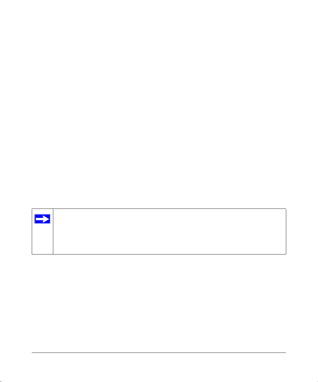
Figure 2-1 shows a UNIX workstation connected to the system
through a virtual terminal protocol (Telnet), and a terminal connecting directly to the console port
through a null-modem cable.
Figure 2-1: Administration Console Access
SNMP Protocol
SNMP is the standard management protocol for multi-vendor IP networks. SNMP supports
transaction-based queries that allow the protocol to format messages and to transmit information
between reporting devices and data-collection programs. SNMP runs on top of the User Datagram
Protocol (UDP), offering a connectionless-mode service.
SNMP Access
With this access method, you can use an external SNMP-based application to manage your
NETGEAR 700 Series Managed Switch.
method.
Switch Management Overview 2-3
Figure 2-2 shows an example of this management
SM-10004-02
Page 16

700 Series Managed Switch User’s Guide for Software v2.1
This management method requires the SNMP agent on the switch and the SNMP Network
Management Station to use the same community string and that the SNMP Network Management
Station is entered in the SNMP Host table on the switch. This management method, in fact, uses
two community strings: the GET community string and the SET community string. If the SNMP
Network management Station only knows the SET community string, it can read from and write to
the MIBs. However, if it only knows the GET community string, it can only read MIBs. The
default GET community string for the switch is ‘public’, and the host table is empty.
Figure 2-2: SNMP-Based Management Method
2-4 Switch Management Overview
SM-10004-02
Page 17

700 Series Managed Switch User’s Guide for Software v2.1
Switch Management Overview 2-5
SM-10004-02
Page 18
Chapter 3
Software Upgrade Procedure
As networking technology advances, NETGEAR will release new versions of the software that
runs the switch. These software releases will provide new capabilities that can extend the useful
life of your switch. This manual is updated whenever there is a change in either the first or second
positions of the software version number. The third position in the software version number
identifies bug fix and patch versions for which this manual is not updated. The upgrade procedure
and the required equipment are described in this chapter.
IP address, Network Mask, and Default Gateway are not affected by upgrading the software.
These settings will be preserved in non-volatile memory (NVRAM).
The upgrade process is accomplished by having the switch boot from a TFTP server instead of its
own NVRAM. To initiate this sequence, the user must set the ‘Next Boot From’ configuration
parameter to ‘Boot from Net’, and then perform a ‘reset’. When the ‘Boot from Net’ option is set,
the switch will start using an image residing on a TFTP server on the network. Be sure that the
TFTP server residing on the network is accessible by the switch. Once completed, the software
version should be verified in the System page.
Note: It is highly recommended, though not necessary, to use a RS-232 serial port
connection to the switch during the software upgrade procedure. When using a Telnet
Session or web interface alone, your connection to the switch will not be available until
the switch has completed its boot up and entered the Spanning Tree forwarding mode.
This can take up to three minutes.
The upgrade procedure below gives the exact steps to follow when using the web interface. The
process is similar with either the CMI or CLI interfaces.
1. Go to Main Menu>Advanced>Advanced Tools>Software Upgrade.
2. Select ‘Boot from Net’ option.
3. Verify information such as the IP address for the TFTP Server and the file name of the new
software image.
4. Save the setting in non-volatile memory. Use the ‘Apply’ button and then the Tools> Save
Configuration screen.
Software Upgrade Procedure 3-1
SM-10004-02
Page 19

700 Series Managed Switch User’s Guide for Software v2.1
5. Restart the system via the Tools>Reset command. Bootstrap will retrieve the new software
image then pass control to it. The system executes the new software image.
The previous software image in non-volatile memory will not be replaced by the new software
image. This enables you to return to the previous image if you do not like the new image.
6. Verify that the new software is loaded by going to the Software Download screen and
checking the Software Release information.
Test your switch to make sure the new image is working correctly. If you decide to keep the
new image, go to Software Download again. Select ‘Boot from Net & Save’ option.
7. Save the setting in non-volatile memory. Use the ‘Apply’ button, and then the Tools> Save
Configuration screen.
8. Restart the system via the Tools>Reset command
The new image should over-write the old image in NVRAM. Verify it by going to the
Software Download screen and checking the Software Release information.
Software Upgrade Procedure 3-2
SM-10004-02
Page 20

700 Series Managed Switch User’s Guide for Software v2.1
3-3 Software Upgrade Procedure
SM-10004-02
Page 21
Chapter 4
Administration Console Telnet Interface
The administration console is an internal, character-oriented, VT-100/ANSI menu-driven user
interface for performing management activities. Using this method, you can view the
administration console from a terminal, PC, Apple Macintosh, or UNIX workstation connected to
the switch’s console port.
Figure 4-1 shows an example of this management method.
Figure 4-1: Administration Console Management Method
Set Up Your Switch Using Direct Console Access
The direct access management method is required when you initially set up your switch.
Thereafter, the convenience and additional features of the Web management access method
(described in chapter 4) make it the best method to manage the switch.
Direct access to the switch console is achieved by connecting the switch’s console port to a
VT-100 or compatible terminal or to a PC, Apple Macintosh, or UNIX workstation equipped with
a terminal-emulation program. This connection is made using the null-modem cable supplied with
the switch.
Administration Console Telnet Interface 4-1
SM-10004-02
Page 22
700 Series Managed Switch User’s Guide for Software v2.1
Examples of terminal-emulation programs include:
• Hyper Terminal, which is included with Microsoft Windows operating systems
• ZTerm for the Apple Macintosh
• TIP for UNIX workstations
This example describes how to set up the connection using a Hyper Terminal on a PC, but other
systems follow similar steps.
1. Click the Windows Start button. Select Accessories and then Communications. Hyper
Terminal should be one of the options listed in this menu. Select Hyper Terminal
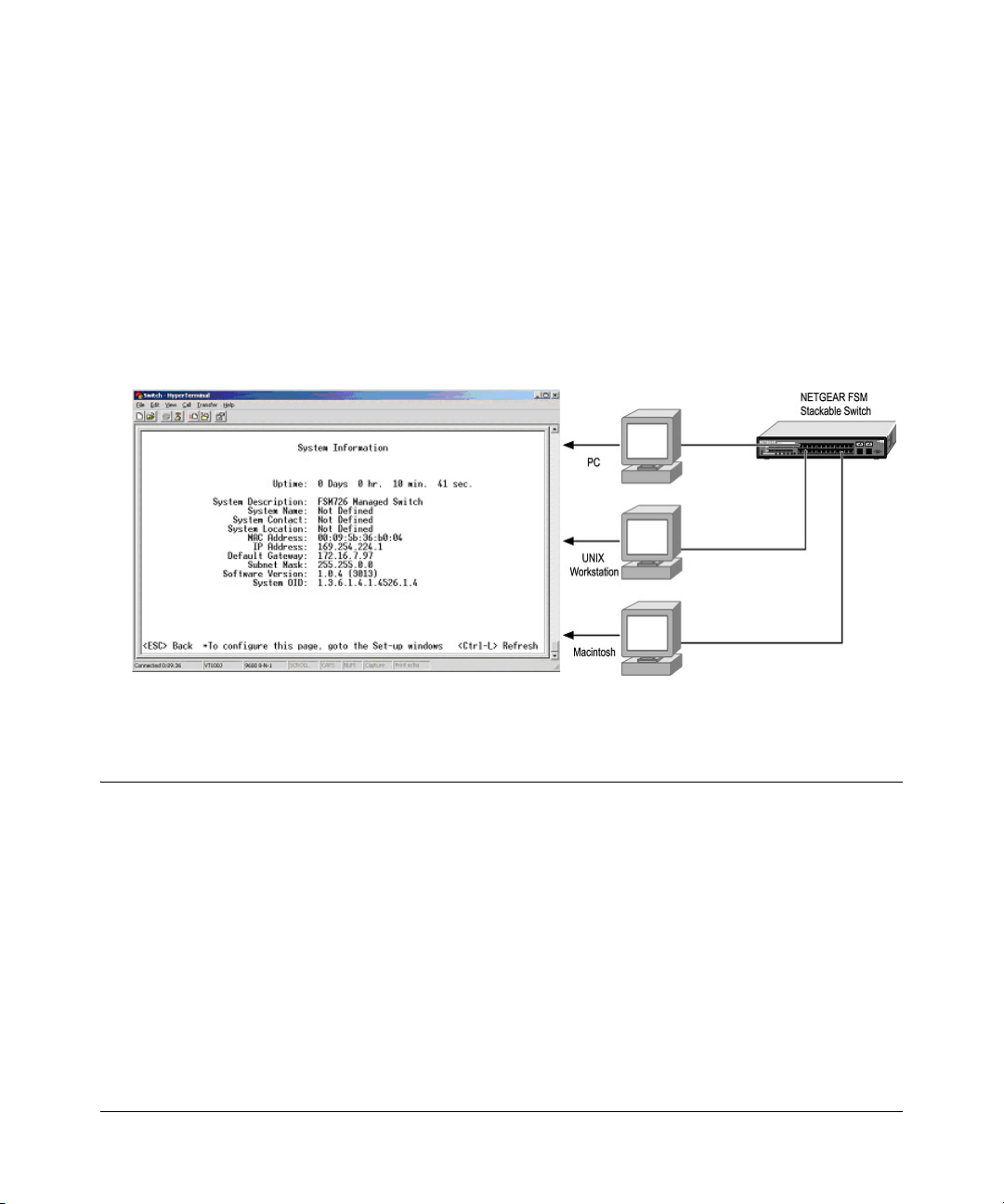
2. The following screen will appear. Enter a name for this connection. In the example below, the
name of the connection is FSM726. Click OK
.
Figure 4-2: Connection Description
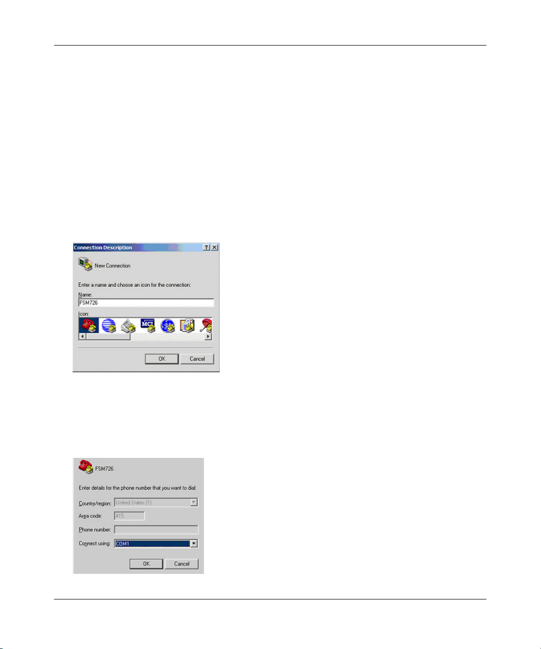
3. The following screen will appear. In the bottom, drop down box labeled Connect Using:, click
the arrow and choose the COM port
to which the switch will connect. In the example below,
COM1 is the port selected. Click OK.
Figure 4-3: COM Port Selection
4-2 Administration Console Telnet Interface
SM-10004-02
Page 23
700 Series Managed Switch User’s Guide for Software v2.1
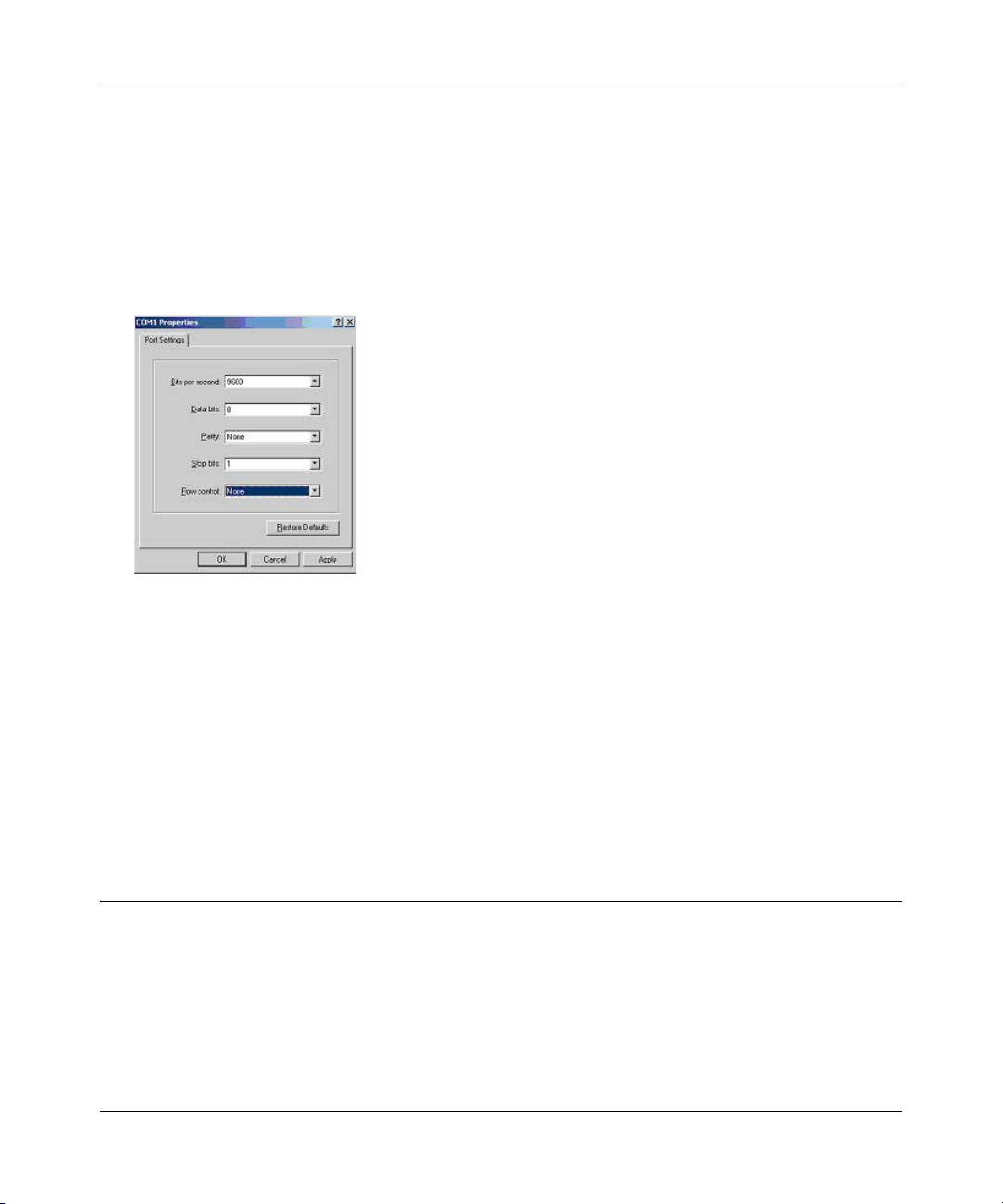
4. When the following screen appears, make sure that the port setting are as follows:
Baud Rate: 9600
Data Bits: 8
Parity: None
Stop Bits: 1
Flow Control: None
Figure 4-4: Connection Settings
5. Click OK.
The Hyper Terminal window will open and you should be connected to the switch. If you do not
get a welcome screen or a system menu, hit the return key.
When attached to the User Interface via a Telnet Session, the following must be set in order to use
the arrow keys: Under the terminal pull down menu choose Properties and make sure the VT100
Arrows option is turned on.
Introduction to the Command Menu Interface
The switch offers a Command Menu Interface (CMI), which is a menu-driven method for
managing the switch, as well as a Command Line Interface (CLI), which uses text inputs to
manage the switch. The CLI is accessed through the CMI, but is not addressed in this chapter.
Chapter 5 discusses the CLI in detail.
Administration Console Telnet Interface 4-3
SM-10004-02
Page 24

700 Series Managed Switch User’s Guide for Software v2.1
There are several characteristics to the CMI pages that are necessary to know before proceeding to
use it. The TAB key or the arrow keys may be used to move within menus and sub-screens. At the
bottom of every screen are some key commands available to the user for that particular screen, as
well as some helpful information.
The common keystrokes and their definitions and intricacies are listed below:
ESC Return to the previous menu or screen, or abort editing
Tab Select field
Ctrl-L Refresh the screen
Ctrl-D Log off (password enabled)
Ctrl-M Move to field (Switch Statistics and Port Configuration menus only)
Ctrl-W Saves current configuration to Non-Volatile RAM (NVRAM)
Spacebar Toggles between possible settings for a field
Enter Select a menu item, edit a field, or accept a value after editing a field
Ctrl-X Delete a table entry
The main menu displays all the sub-menus that are available. Striking ‘Enter’ when an option is
highlighted will confirm the choice of the specified sub-menu. The ‘hotkey’ or letter in front of
each menu option can also be typed to directly choose that option. As shown below, there are six
menu items to choose from:
Figure 4-5: Main Menu
To logout of the user interface, hit Ctrl-D at any time during your telnet session. You will be
brought back to the login screen (password enabled) or Main Menu (password disabled).
4-4 Administration Console Telnet Interface
SM-10004-02
Page 25

700 Series Managed Switch User’s Guide for Software v2.1
Main Menu> System
This screen displays the main menu System Information options. The user definable options are:
System Name, System Contact, System Location, IP Address, Default Gateway, and Subnet Mask.
The System OID option is used for production testing.
Figure 4-6: System Information
Main Menu> Status
There are two Status sub-menus: Switch Statistics and MAC Address Table.
Main Menu> Status >Statistics
The Port-ID field allows you to choose a port to be observed. To get to the left side, use Ctrl-M to
move to that field. The screen displays basic statistics associated with the highlighted port.
Administration Console Telnet Interface 4-5
SM-10004-02
Page 26
700 Series Managed Switch User’s Guide for Software v2.1
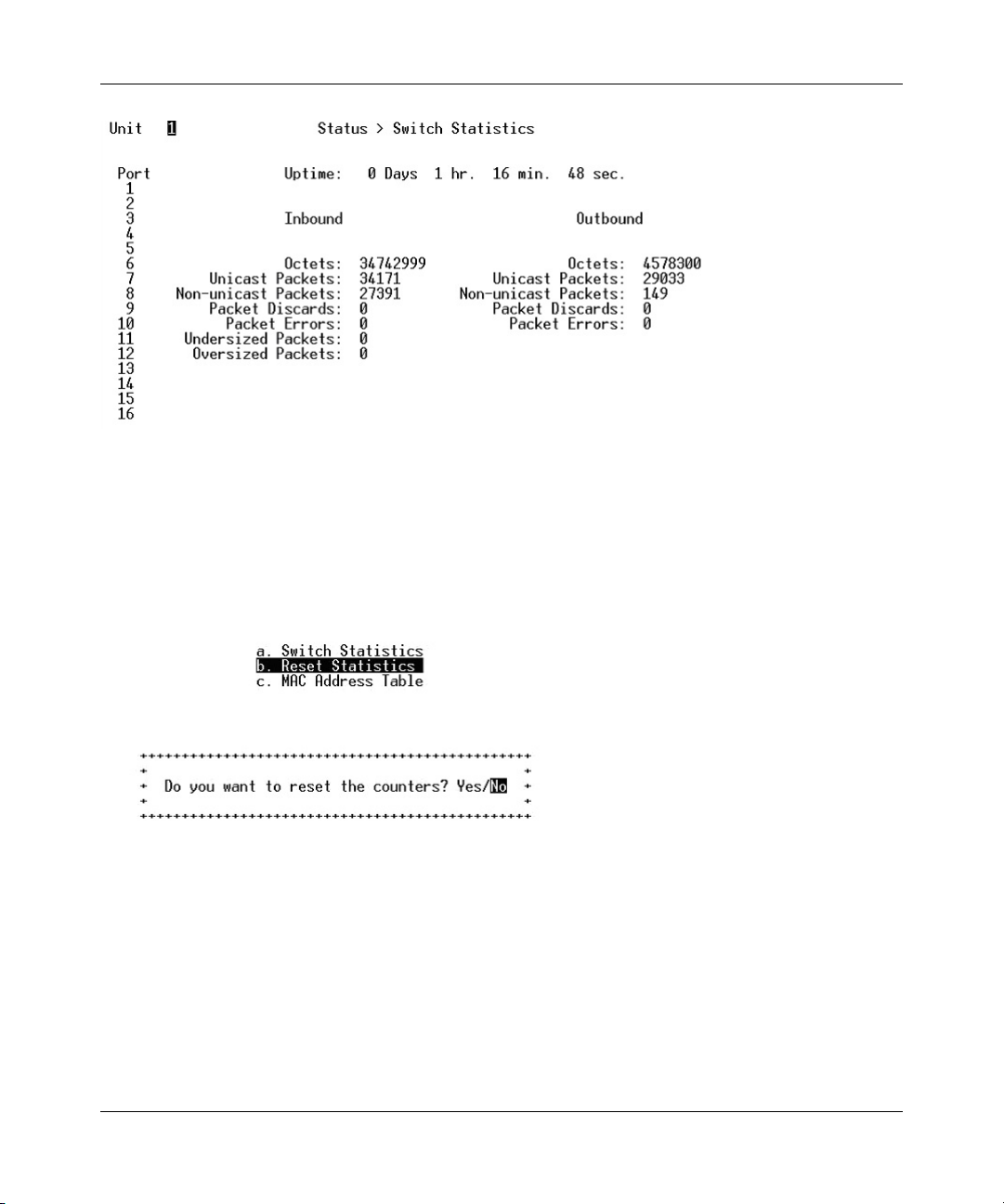
Figure 4-7: Switch Statistics
Main Menu> Status >Statistics Rest
The Statistic Reset menu allows the user to reset the statistic counter to zero. When you choose
this option, a prompt will appear asking you for a confirmation. Once the confirmation is made,
the statistics counters will be reset to zero.
Figure 4-8: Reset Switch Statistics
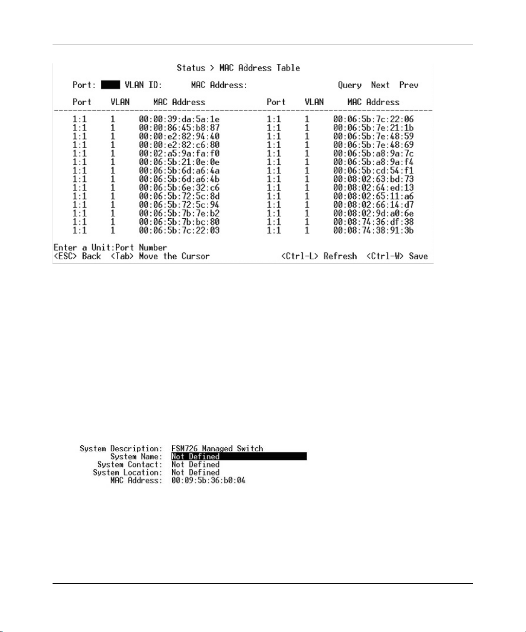
Main Menu> Status > MAC Address Table
The MAC Address lookup table displays the MAC addresses that are currently in the address
database. When addresses are in the database, the packets intended for those addresses are
forwarded directly to those ports. You can filter out addresses in the table by port, VLAN, or MAC
address by entering a value in those fields, and selecting ‘Query.’
4-6 Administration Console Telnet Interface
SM-10004-02
Page 27
700 Series Managed Switch User’s Guide for Software v2.1
Figure 4-9: Address Manager: MAC Address Table
Main Menu> Set-Up
There are three sub-menus at Set-Up menu, System Configuration, IP Configuration, and Port
Configuration.
Main Menu> Set-Up> System Configuration
The System Configuration allows the user to enter a number of system-related information for
easy reference in the future. Such items include System Name, Contact Person, and System
Location. The MAC address is also shown, but it is not user configurable.
Figure 4-10: System Configuration
Main Menu> Set-Up> IP Configuration
This menu manages the IP related information of the system.
Administration Console Telnet Interface 4-7
SM-10004-02
Page 28

700 Series Managed Switch User’s Guide for Software v2.1
IP Assignment Mode. The user manually enters IP related information
• Bootstrap Protocol, which allows the switch to discover its own IP address from a BootP
server on the network
• DHCP, which allows the switch to accept DHCP broadcasts from a DHCP server and
automatically configures IP related information
The default setting is DHCP, to enable quick and easy set-up. However, since you need to know
the IP address of your switch to remotely manage it and DHCP assignments can change, change
the IP assignment mode from DHCP to manual after the switch has obtained its IP address.
Figure 4-11: Set-up Manager: IP Configuration
Note: In DHCP mode, if the switch fails to get a DHCP assignment, the switch defaults to
192.168.0.1 as its IP address.
If you are in the manual mode and need to configure the IP information, enter a site-specific IP
address, Gateway Address, and Network Mask (or subnet mask). Consult your network
administrator for the information.
Press Ctrl-W to save any changes to NVRAM.
Main Menu> Set-Up> Port Configuration
On this page, you can set up the port characteristics related to link operations. All of the
parameters on this page are toggle settings. To change, or toggle, between options, hit Ctrl-M to
move the curser to the ports field and simply strike the space bar when the appropriate option is
highlighted. To modify ports 17 to 26, you must tab through ports 1 to 16. The comments field is
available for you to enter a description of the port.
4-8 Administration Console Telnet Interface
SM-10004-02
Page 29

700 Series Managed Switch User’s Guide for Software v2.1
Figure 4-12: Port Configuration
Admin field. Allows you to Enable or Disable the port.
State field. The State field displays the Spanning Tree State of the port (Blocking, Listening,
Learning, Forwarding, or Disabled). You can only observe the status of the ports; you cannot
modify this field. The Spanning Tree Protocol controls this field.
Rate/Duplex field. Offers the choice of Full-duplex, Half-duplex, or Auto negotiation.
Enabling auto-negotiation on a port allows a port to sense the communication speed and negotiate
the duplex mode (full duplex or half duplex) automatically. The ports will select the highest
possible throughput. The port can auto-negotiate with any port that is compliant with IEEE
802.3u. If the other port is not IEEE802.3u compliant, the port will default to half-duplex, 10
Mbps mode. Users can operate the communication speed and duplex mode manually.
Flow Control. Allows you to enable or disable Flow Control.
Flow control is a protocol that prevents packets from being dropped by reducing the amount of
traffic to a level that can be accommodated. If enabled on both ends of a connection, it will
prevent the sender from sending data until the receiver can accept it. This switch complies with
the IEEE802.3x flow control standard.
Comments. Allows you to name the port or make notes.
Administration Console Telnet Interface 4-9
SM-10004-02
Page 30

700 Series Managed Switch User’s Guide for Software v2.1
Gigabit Ports. For the gigabit ports on each switch, the port type may be chosen. The default is
that the port uses the RJ-45 interface (GT). You can select the GBIC interface (GB) by switching
the port type from ‘GT’ to ‘GB’. This can be done by hitting the space bar when the cursor is on
the port number.
Note: enabling the GBIC connector for a Gigabit Ethernet port disables the built-in 1000BASE-T
port. GBIC ports do not support Auto Negotiation. You must manually configure the GBIC port.
The default values are 1000 Mbps, full duplex
.
Main Menu> Set-Up> GBIC
On this page, you can set up the port characteristics related to GBIC or copper media.
Figure 4-13: GBIC Port Configuration
All of the parameters on this page are toggle settings. To change, or toggle, between options, hit
Ctrl-M to move the curser to the ports field and simply strike the space bar when the appropriate
option is highlighted.
Main Menu> Tools
These system tools are provided:
• Save Configuration to NVRAM
• Restore Factory Values
• Reset Switch
4-10 Administration Console Telnet Interface
SM-10004-02
Page 31

700 Series Managed Switch User’s Guide for Software v2.1
After making changes to any of the information on the screens in the console interface, users must
save the changed settings to NVRAM. Save Configuration to NVRAM.
Figure 4-14: Save Settings to NVRAM & Restore Factory Values
• To Save Configuration to NVRAM, select the Save option, and press either ‘Enter’ or ‘Y’ to
save the configuration to NVRAM.
• To Restore Factory Values, select the Restore Factory Values to reset the switch parameters to
their original default settings. In order for changes to take effect, you must Reset the switch.
Note: Network IP settings (i.e. IP address, Gateway Address, Network Mask) will not be
affected by this command.
• To use the Reset Switch option, select it from the menu, which will restart the switch.
Resetting the switch is the equivalent of turning the power off and on. Resetting the switch
will clear the statistical counters to zero.
Main Menu> Security
This screen allows the user to enable or disable the web and/or telnet interfaces, as well as change
the user name and password. To use password protection, you must enable Password Protection.
User names and passwords are case sensitive and can be up to 20 characters long. The factory
default password is
Administration Console Telnet Interface 4-11
password in lower case letters.
SM-10004-02
Page 32

700 Series Managed Switch User’s Guide for Software v2.1
Figure 4-15: Security
Note: Using telnet, you can only enable/disable the web interface. You cannot enable/disable the
telnet interface.
If you forget your password, contact NETGEAR technical support at 1-888-NETGEAR (in North
America).
Main Menu> Advanced
The Advanced page allows professional users to operate more complicated features of the device,
which include VLAN, Spanning Tree, Port Trunking, Multimedia support (IGMP), traffic
prioritization, SNMP, and port mirroring. These features are powerful and can degrade or disable a
network if improperly used. The eleven sub-menus are introduced below.
• Advanced Security: The user can configure the security settings of the switch by choosing
either to use basic password or RADIUS server to authenticate the user attempting to
configure the switch. In addition, the user can also set up IP filtering to allow only approved
users on the network to configure the switch.
• Port-Based Authentication: The user can configure the ports of the switch for authentication
through a RADIUS server to authenticate the user attempting to connect to the network
through a port on the switch.
• Port Mirroring: Users can designate a port for monitoring traffic from one or more other ports
or of a single VLAN configured on the switch. The switch monitors the network activity by
copying all traffic from the specified monitoring sources to the designated monitoring port, to
which a network analyzer can be attached.
4-12 Administration Console Telnet Interface
SM-10004-02
Page 33

700 Series Managed Switch User’s Guide for Software v2.1
• Port Trunking: a feature that allows multiple links between switches to work as one virtual link
(aggregate link). Trunks can be defined for similar port types only. For example, a 10/100 port
cannot form a Port Trunk with a gigabit port. For 10/100 ports, trunks can only be formed
within the same bank. A bank is a set of eight ports. Up to four trunks can be operating at the
same time. Toggle the ports to the correct trunk number to set up a trunk. After clicking Apply,
the trunk will be enabled. Spanning Tree will treat trunked ports as a single virtual port.
• Virtual Cable Tester: The user can use this feature to test the continuity of the cable circuit.
• Advanced Tools: The user can upgrade the software of the switch or save/load the switch
configuration file to a TFTP server.
• Traffic Management: Class of Service (CoS), also referred to as Quality of Service (QoS), is a
way of managing traffic in a network, by treating different types of traffic with different levels
of service priority. Higher priority traffic gets faster treatment during times of switch
congestion. Priority can be based on VLAN tags, ports, or Differentiated Service Code Points
(DSCP).
• Broadcast Control: The user can configure the threshold for the maximum broadcast packets
per port.
• VLANs: A Virtual Local Area Network (VLAN) is a means to electronically separate ports on
the same switch from a single broadcast domain into separate broadcast domains. By using
VLAN, users can group by logical function instead of physical location. There are 64 VLAN
supported on this switch.
• Spanning Tree Protocol (STP) ensures that only one path at a time is active between any two
network nodes. There are maybe more than two physical path between any two nodes for
redundant paths; STP ensures only one physical path is active and the others are blocked. STP
will prevent an inadvertent loop in a network, which can disable your network due to a
“Broadcast storm”, the result of a broadcast message traveling through the loop again and
again.
• MAC: MAC address table. This menu allows you to set the aging time, as well as entering
static MAC addresses to the switch.
• Multimedia Support (IGMP): The Internet Group Management Protocol (IGMP) is an Internet
protocol that provides a way for network devices to report multicast group membership to
adjacent routers.
• SNMP: You can use an SNMP-based Network Management Software program to manage
your switch. This menu allows you to set up the appropriate tables to enable the switch to
respond to SNMP queries.
• Command Line: A user interface that allows the user to configure the switch via a command
line interface. See chapter 5 for information about the Command Line Interface (CLI)
Administration Console Telnet Interface 4-13
SM-10004-02
Page 34

700 Series Managed Switch User’s Guide for Software v2.1
Main Menu> Advanced> Advanced Security
This menu option allows you to configure the advanced security settings of the switch to limit the
access to the management interfaces.
Figure 4-16: Advanced Security
There are two advanced security options beyond the basic password protection: RADIUS client
authentication and IP Filtering. If you have a RADIUS server on your network, you can have
authentication of management access done through the RADIUS server. This does not affect
traffic passing through the switch, but only authenticates access to the switch management. The
same is true for IP Filtering. Here, you can allow only users with specific IP addresses to access
the management features, thus preventing unauthorized personnel from configuring to the switch.
Main Menu> Advanced> 802.1x Port-Based Authentication
This menu option allows you to configure the 802.1x security settings of the switch to require
RADIUS authorization to access ports on the switch.
Figure 4-17: Port-Based Authentication
4-14 Administration Console Telnet Interface
SM-10004-02
Page 35

700 Series Managed Switch User’s Guide for Software v2.1
802.1x port-based authentication provides RADIUS client authentication and data encryption
features (see
RADIUS server on your network, you can have authentication of port access done through the
RADIUS server. This does affect traffic passing through the switch, which can be helpful is
securing your network from wireless eavesdropping when a wireless access point is connected to
the switch. To enable 802.1x, provide the IP address of the RADIUS server, and the shared secret
authentication key. The re-authorization timer determines how frequently the session will refresh
the data encryption with a new key.
Appendix C, “802.1x Port-Based Authentication Overview”). If you have a
Main Menu> Advanced> Port Mirroring
This menu option allows you to enable the Port Mirroring capability (see Figure 6-13). You need
to specify both the Source and Monitor port.
Figure 4-18: Port Mirroring
The Monitor port will show a copy of every packet that arrives and departs at the Source port.
Main Menu> Advanced> Port Trunking
Port Trunking is a feature that allows multiple links between switches to work as one virtual link
or aggregate link.
Administration Console Telnet Interface 4-15
SM-10004-02
Page 36

700 Series Managed Switch User’s Guide for Software v2.1
Figure 4-19: Port Trunking
Trunks can be defined for similar port types only. For example, a 10/100 port cannot form a Port
Trunk with a gigabit port. For 10/100 ports, trunks can only be formed within the same bank. A
bank is ports 1 to 8, ports 9 to 16, ports 17 to 24, or port 25 and port 26 (using an FSM726 as an
example), on the same switch unit. Up to four trunks can be enabled at the same time. To set up a
trunk, use the space bar to select the ports that will participate in the trunk. Spanning Tree will treat
trunked ports as a single virtual port.
Note: You must use straight-though cables for all links in the trunk. Do not use crossover cables.
And, you must disable auto-negotiation on the ports in a trunk prior to setting up the trunk.
Main Menu> Advanced> Virtual Cable Tester
The virtual cable tester feature lets you test the continuity of the GBIOC cable circuit.
Figure 4-20: Virtual Cable Tester
The results are reported for the selected port. The test can take up to one minute.
4-16 Administration Console Telnet Interface
SM-10004-02
Page 37

700 Series Managed Switch User’s Guide for Software v2.1
Note: Only the console menu will let you run the virtual cable tester on any port. Other
management interfaces require port access and therefore cannot reliably test the cable continuity of
the port they are using to access the switch.
Main Menu> Advanced> Advanced Tools
This menu provides you with the ability to upgrade the software for the switch as well as saving or
loading the switch configuration file to a TFTP server.
Main Menu> Advanced> Advanced Tools> Software Upgrade
If new improvements to the software that runs the switch become available, this menu enables you
to upgrade your switch to the new software release.
Figure 4-21: Software Upgrade
Once the IP address of the TFTP and the path location of the new software image file is properly
configured, the user can choose to boot the switch using one of three options.
Please refer to
Chapter 2 Software Upgrade Procedure when updating software.
• Net option:. This option allows you to try out a new image before upgrading. It requires a
TFTP filename and a server IP address to retrieve the specified image from the given IP
address. The new image will not overwrite the one in non-volatile memory.
• Net & save option.This option requires the same setup as the Net option, i.e. TFTP server and
a new image. However, it copies the image to non-volatile memory directly and then the
system boots from non-volatile memory
Warnin g: The previous image in non-volatile memory will be lost when the procedure
completes.
Administration Console Telnet Interface 4-17
SM-10004-02
Page 38

700 Series Managed Switch User’s Guide for Software v2.1
• Last Saved option. The system will boot from non-volatile memory. This option will
automatically show up after the ‘Net & save’ option is selected and the unit is reset.
Main Menu> Advanced> Advanced Tools> Configuration Management
This menu allows you to save your configuration, in case you want to keep a copy for back-up
purposes.
Warnin g: Do not edit your configuration file. Editing your file can cause your switch to lose its
management capabilities, and possibly degrade its performance. Editing the configuration file will
void your warranty.
Figure 4-22: Configuration Management
This menu also allows you to download your configuration file back to the switch to restore your
settings.
Main Menu> Advanced> Traffic Management
Traffic management covers the methods to improve the performance of your network by
differentiating traffic and limiting excess broadcast traffic.
Figure 4-23: Traffic Management
4-18 Administration Console Telnet Interface
SM-10004-02
Page 39

700 Series Managed Switch User’s Guide for Software v2.1
There are two means to differentiate traffic with this switch- VLAN tags or Differentiated Service
Code Points (DSCP) in the header of data packets. By using either the VLAN tags (port-based) or
DSCP (DiffServ), you can configure the switch so that certain traffic will take priority over less
critical traffic.
Main Menu> Advanced> Traffic Management> Port Priority
Figure 4-24: Traffic Prioritization
Main Menu> Advanced> Traffic Management> DiffServ
Differentiated Service (DiffServ) uses a priority tag in the packet, the Differentiated Service Code
Point (DSCP), to determine the priority of the packet.
Figure 4-25: DiffServ
Administration Console Telnet Interface 4-19
SM-10004-02
Page 40

700 Series Managed Switch User’s Guide for Software v2.1
There are 64 different tags available. This menu maps the various DSCP tags to the two output
queues on each port.
Main Menu> Advanced> Traffic Management> Broadcast Control
Broadcast control lets you set a threshold for the number of broadcast packets sent over a port.
Figure 4-26: Broadcast Control
Main Menu> Advanced> VLANS
A Virtual Local Area Network (VLAN) is a means to electronically separate ports on the same
switch from a single broadcast domain into separate broadcast domains.
Figure 4-27: VLANS
By using VLAN, users can group by logical function instead of physical location. This switch
supports up to 64
VLANs. This switch supports static, port-based VLANs. The VLAN Setup
options are as follows:
Main Menu> Advanced> VLANS> VLAN Admin
Up to 64 VLANs with unique ID numbers and names can be added. VLAN ID numbers must be in
the range of 1-4094. Per industry standard, the default VLAN has an ID of 1.
4-20 Administration Console Telnet Interface
SM-10004-02
Page 41

700 Series Managed Switch User’s Guide for Software v2.1
Figure 4-28: VLAN Administration
To add a VLAN, enter a unique numeric VLAN ID and then enter a unique VLAN name.
To remove a port or an entire VLAN, just press Ctrl-X anywhere on the line of the VLAN.
Main Menu> Advanced> VLANS> VLAN Membership
This matrix allows for real time management of up to 64 VLANs.
Figure 4-29: VLAN Membership
To add a port to a VLAN, position the cursor in the desired matrix location and toggle the options
with the SPACE bar.
A ‘U’ or ‘T’ will be displayed for each port assigned to the VLAN, where ‘U’ stands for untagged
and ‘T’ for tagged. If a port is an untagged member of a VLAN, the VLAN tag will be striped
from the frame before it is sent out that port. If the port is a tagged member of a VLAN, the
VLAN tag will stay in the frame when it is sent. A ‘_’ space indicates that the port is not a
member of the particular VLAN, and will not receive or forward any traffic for that VLAN. VLAN
tagging is a standard set by the IEEE to facilitate the spanning of VLANs across multiple switches.
(Reference: Appendix B and IEEE Std 802.1Q-1998 Virtual Bridged Local Area Networks).
Main Menu> Advanced> VLANS> VLAN Ports
All untagged packets entering the switch will by default be tagged with the ID specified by the
port’s PVID.
Administration Console Telnet Interface 4-21
SM-10004-02
Page 42

700 Series Managed Switch User’s Guide for Software v2.1
Figure 4-30: PVID Settings
This screen allows you to specify the PVID for each port. The number next to each port indicates
which PVID is set for each port. Following industry standards, PVID 1 is the default PVID.
Main Menu> Advanced> Spanning Tree
This switch is compliant with IEEE802.1D Spanning Tree Protocol (STP).
Figure 4-31: Spanning Tree
STP ensures that only one path at a time is active between any two network nodes. There may be
more than one physical path between any two nodes, forming a loop, either created for redundancy
or by accident. STP ensures only one physical path is active and the others are blocked. If a loop is
created for redundancy, STP will monitor the two paths and activate the stand-by path if the
primary path fails. If a loop was created inadvertently, STP will disable one of the two paths. A
loop in a network can disable your network by causing a “Broadcast storm”, the result of a
broadcast message traveling through the loop again and again.
Main Menu> Advanced> Spanning Tree> Bridge Settings
Spanning Tree can be enabled or disabled in this screen.
4-22 Administration Console Telnet Interface
SM-10004-02
Page 43

700 Series Managed Switch User’s Guide for Software v2.1
Figure 4-32: Spanning Tree: Bridge Settings
When Spanning tree is used in conjunction with a set of aggregated ports, otherwise known as a
port trunking, Spanning Tree will treat the trunk as a single virtual port.
• Enable: There are four other tunable parameters to be addressed when enabled.
Hello Time Time between configuration messages sent by the Spanning Tree algorithm
Max Age Amount of time before a configuration message is discarded by the system
Forward Delay Amount of time system spent transitioning from the ‘learning’ to the
‘listening’ to the ‘forwarding’ states
Bridge Priority Priority setting among other switches in the Spanning Tree
• Disable: Disable Spanning Tree algorithm on the system.
Main Menu> Advanced> Spanning Tree> Port Settings
For the Port Settings options, you can specify Spanning Tree port priority, cost, and Fastlink
parameters for each port.
Administration Console Telnet Interface 4-23
SM-10004-02
Page 44

700 Series Managed Switch User’s Guide for Software v2.1
Table 4-1. STP Port Setting Parameters
PARAMETERS RANGE DESCRIPTION
Prty (Priority) 0-255 STP uses this to determine which path (which port) to use for
forwarding. The port with the lowest number has the highest priority.
Cost 1-65535 The switch uses this to determine which port is the forwarding port
when the priority is equal. All other factors equal, the path with the
lowest cost to the root bridge will be the active path. The estimated
path cost is the industry standard for the port speed. The default path
cost is the maximum speed for the port.
Fastlink Enabled or
Disabled
When a Fastlink enabled port running standard STP is
connected, it will go through the STP negotiation (listening ->
learning -> forwarding or blocking) before it will be fully
available.
Figure 4-33: Spanning Tree: Port Settings
Fastlink in STP mode. If a client is trying to access a server through the switch running the STP
negotiation, it will not be able to connect to it immediately. This can be a problem for some
networks. Fastlink mode solves this problem by setting the port to direct forwarding mode, thus
allowing any server access request to be forwarded. Fastlink mode can cause temporary loops in
your network, but STP will find and eliminate them. Fastlink is best used on end node ports, i.e.
ports connected to PCs or servers, and not on uplink ports to other switches.
Main Menu> Advanced> MAC Address Manager
Static Address and Address Aging can be configured here.
4-24 Administration Console Telnet Interface
SM-10004-02
Page 45

700 Series Managed Switch User’s Guide for Software v2.1
Figure 4-34: MAC
Main Menu> Advanced> MAC Address Manager> Address Aging
The aging time is the amount of time that an entry is kept in the bridge tables prior to being purged
(or aged). The range (in parentheses) represents the minimum and the maximum values that the
timer can be set. The industry standard default is 300 seconds.
Main Menu> Advanced> MAC Address Manager> Static Addresses
The Static Address Table allows you to specify Media Access Control (MAC) addresses for
specific ports that will not be purged from the bridge table by the aging function.
Figure 4-35: MAC: Static Address
• Adding an entry. Type the MAC address under the first column, and hit Enter. Then, enter the
port number associated with that MAC address.If all the information is correct, the new entry
will appear in the list, which is listed by port ID. Otherwise, an error message will be displayed
and the cursor will return to the MAC Address field.
• Removing an entry. Tab to the entry and press Ctrl-X. This will erase the MAC address from
NVRAM. This action takes effect immediately; you do not need to use Ctrl-W to save the
update.
Administration Console Telnet Interface 4-25
SM-10004-02
Page 46

700 Series Managed Switch User’s Guide for Software v2.1
Main Menu> Advanced> Multimedia Support
In networks where multimedia applications generate multicast traffic, Internet Group Multicast
Protocol (IGMP) can greatly reduce unnecessary bandwidth usage by limiting traffic forwarding
that is otherwise broadcast to the whole network. Enabling IGMP will allow individual ports to
detect IGMP queries, report packets, and manage IP multicast traffic through the switch.
Main Menu> Advanced> Multimedia Support> Enable/Disable IGMP
Figure 4-36: Multimedia Support
• Enable. The system will detect IGMP queries, report packets, and manage IP multicast traffic
through the switch
• Disable. The switch will forward traffic and disregard any IGMP requests.
Main Menu> Advanced> Multimedia Support> Static Multicast Administration
Use this menu to configure permanently reachable multicast groups.
4-26 Administration Console Telnet Interface
SM-10004-02
Page 47

700 Series Managed Switch User’s Guide for Software v2.1
Figure 4-37: Static Multicast Administration
The Static Multicast Administration menu lets you create individual groups by entering MAC
addresses for your static multicast group. The membership of each group is configured in the
Static Multicast Membership menu.
Main Menu> Advanced> Multimedia Support> Static Multicast Membership
Once the static multicast groups are defined in the Static Multicast Administration menu, you can
use this menu to specify the membership of each group by specifying the ports that belong to each
group.
Figure 4-38: Static Multicast Membership
Administration Console Telnet Interface 4-27
SM-10004-02
Page 48

700 Series Managed Switch User’s Guide for Software v2.1
Main Menu> Advanced> SNMP
Figure 4-39: SNMP Management
You can manage this switch using the Simple Network Management Protocol (SNMP) from a
network management station. To do so, you must configure your switch to participate in the SNMP
community and you must add the SNMP host agent to the host table. This prevents unauthorized
SNMP access to your switch from non-approved SNMP hosts.
Support for these Standard MIBs is included:
• MIB II (RFC1213)
• Ethernet Interface MIB (RFC1643)
• Bridge MIB (RFC1493)
• Private Enterprise MIB (see the Resource CD for Managed Switches)
• 4-Group RMON (RFC1757)
Main Menu> Advanced> SNMP> Community Table
You can create up to eight community strings which combine GET, SET, and TRAP privileges.
Figure 4-40: SNMP Management: Community Table
4-28 Administration Console Telnet Interface
SM-10004-02
Page 49

700 Series Managed Switch User’s Guide for Software v2.1
These community strings need to be set prior to setting host access, as the host table depends on
the existence of community strings. The public string has GET privileges by default.
Main Menu> Advanced> SNMP> Host Table
The screen, shown in Figure 6-29, grants a host the access rights to the switch. Host Authorization
is a security feature to limit people who are not listed in the host table from accessing the switch
using SNMP.
Figure 4-41: SNMP Management: Host Table
To add a host, enter the host name, IP address, and the community string. Press Enter after each
entry to move to the next field. In the Status field, press the Spacebar until the desired Status is
displayed. Press Ctrl-W to save all changes.
Main Menu> Advanced> SNMP> Trap Settings
When on, the system will generate an SNMP trap upon a host authorization failure. This failure
occurs when a host tries to gain access to the system but the host’s IP is not in the SNMP host
table.
Figure 4-42: SNMP Management: Trap Settings
With authentication traps enabled, the system generates a SNMP trap when a host authorization
fails. Hosts in community strings with TRAP privileges are notified when a trap occurs.
Administration Console Telnet Interface 4-29
SM-10004-02
Page 50

700 Series Managed Switch User’s Guide for Software v2.1
4-30 Administration Console Telnet Interface
SM-10004-02
Page 51

Chapter 5
Web-Based Management Interface
Your NETGEAR 700 Series Managed Switch provides a built-in browser interface that lets you
configure and manage it remotely using a standard Web browser such as Microsoft Internet
Explorer 5.0 or later or Netscape Navigator 6.0 or later.
This interface also allows for system monitoring and management of the switch. The ‘help’ page
will cover many of the basic functions and features of the switch and it’s web interface.
When you configure the switch for the first time from the console, you can assign an IP address
and subnet mask to the switch. Thereafter, you can access the switch’s Web interface directly using
your Web browser
your Web browser to manage the switch from a central location, just as if you were directly
connected to the switch’s console port. Figure 4-1 shows this management method.
by entering the switch’s IP address into the address bar. In this way, you can use
Figure 5-1: Web Management Method
Web-Based Management Interface 5-1
SM-10004-02
Page 52

700 Series Managed Switch User’s Guide for Software v2.1
Web Based Management Overview
The 6 menu options available are: System, Status, Set-up, Tools, Security, and Advanced. There is
a help menu in the top of right side of screen; you can click the ‘help’ or the question mark to read
the help menu.
The help menu contains:
• Web-Based Management Introduction to the Web management features.
• Device Management Introduction of the basic icons and management of the device
• Interface Operations Describes Web browser requirements, and common commands
• Product Overview Describes supported SNMP and Web management features
• Summary of Features Feature List
Within the various browser interface pages, there are several buttons that you can use. Their
names and functions are below:
• Reload: Pulls that screen’s data from current values on the system
• Apply: Submits change request to system and refreshes screen data
• Add: Adds new entries to table information and refreshes screen data
• Remove: Removes selected entries from table and refreshes screen data
• Reset: Resets the system, which is equivalent to power off /on.
• Restore: Restores system factory default values, except password and IP.
• Query: System will retrieve the useful information in database.
5-2 Web-Based Management Interface
SM-10004-02
Page 53

System Information
700 Series Managed Switch User’s Guide for Software v2.1
Figure 5-2: System information page
This welcome page displays system information, such as:
• System Description
•System Name
• System Contact
• System Location
• Current Local Time (according to your computer)
• System Uptime
• MAC Address
• IP Address
• Subnet Mask
• Default Gateway
• Software Version
• System OID (used for production testing)
Web-Based Management Interface 5-3
SM-10004-02
Page 54

700 Series Managed Switch User’s Guide for Software v2.1
These parameters are not editable from this screen. Some of these can be modified in the Set Up>
System Configuration page or the Set Up> IP Configuration page.
Status Menus
The Status page contains 5 menus.
Figure 5-3: Status Menu navigation
• Switch Statistics
• Port Statistics
• Error Statistics
•Most Active Ports
• Reset Statistics
• Port Settings
• MAC Address Table
Each of these menus is covered in the following sections.
5-4 Web-Based Management Interface
SM-10004-02
Page 55

700 Series Managed Switch User’s Guide for Software v2.1
Status > Switch Statistics
The Switch Statistics Chart allows you to compare one type of statistic across all the ports. You
can reset the counters in the Reset Statistics page.
Figure 5-4: Switch Statistics
You can configure the following options on the Switch Statistics Chart:
• Statistics The type of system data to be monitored
• Refresh Rate The time interval between automatic refreshes (5, 10, 15, 30 seconds)
• Color The color setting for the chart
There are 24 kinds of Statistics that you can review on this screen:
• Inbound Octet Rate: Received Byte per second.
• Inbound Unicast Packet Rate: Received Unicast packet per second.
• Inbound Non-unicast Packet rate: Received Non-unicast packet per second.
• Inbound Discard Rate: Received and is discarded packet per second.
• Inbound Error Rate: Received error packet per second.
• Outbound Octet Rate: Transmitted byte per second.
• Outbound Unicast Packet Rate: Transmitted unicast packet per second.
Web-Based Management Interface 5-5
SM-10004-02
Page 56

700 Series Managed Switch User’s Guide for Software v2.1
• Outbound Non-unicast Packet Rate: Transmitted non-unicast packet per second.
• Outbound Discard Rate: Transmitted and is discarded packet per second.
• Outbound Error Rate: Transmitted error packet per second.
• Ethernet Undersize Packet Rate: Less than 64byte length packet per second.
• Ethernet Oversize Packet Rate: More than 1518byte length packet per second
• Inbound Octets: Received bytes
• Inbound Unicast Packets: Received unicast packet
• Inbound Non-unicast Packets: Received non-unicast packet
• Inbound Discards: Received and is being discarded packet.
• Inbound Errors: Received and is a error packet
• Outbound Octets: Transmitted byte
• Outbound Unicast Packets: Transmitted unicast packet
• Outbound Non-unicast Packets: Transmitted non-unicast packet.
• Outbound Discards: Transmitted and is being discarded packet
• Outbound Errors: Transmitted and is an Error packet.
• Ethernet Undersize Packets: Less than 64byte length packet
• Ethernet Oversize Packets: more than 1518 byte length packet.
5-6 Web-Based Management Interface
SM-10004-02
Page 57

Status > Port Statistics
Figure 5-5: Port Statistics
700 Series Managed Switch User’s Guide for Software v2.1
The Port Statistics Chart shows all the statistic types for one port over time. You can reset the
counters in the Reset Statistics page.
• Port The port on which data will be monitored.
• Refresh Rate The time interval between automatic refreshes
• Color The color setting for the data
There are 12 kinds of Port Statistics
• Inbound Octets: Received bytes
• Inbound Unicast Packets: Received unicast packet
• Inbound Non-unicast Packets: Received non-unicast packet
• Inbound Discards: Received and is being discarded packet.
• Inbound Errors: Received and is a error packet
• Outbound Octets: Transmitted byte
• Outbound Unicast Packets: Transmitted unicast packet
• Outbound Non-unicast Packets: Transmitted non-unicast packet.
Web-Based Management Interface 5-7
SM-10004-02
Page 58

700 Series Managed Switch User’s Guide for Software v2.1
• Outbound Discards: Transmitted and is being discarded packet
• Outbound Errors: Transmitted and is an Error packet.
• Ethernet Undersize Packets: Less than 64byte length packet
• Ethernet Oversize Packets: more than 1518 byte length packet.
Status > Error Statistics
Figure 5-6: Error Statistics
The Error Statistics Graph allows you to chart one type of statistic for any combination of ports. In
the case of the Error Statistics Graph, the chart will present data across time so that fluctuations in
time can be easily seen.
All charts have a maximum ceiling of more than 2.1 billion (2,147,483,647). You can see the value
of each bar or line in the chart by clicking on the bar. The following will outline the settings for
each type of graph.
• Statistics The type of system errors to be monitored
• Refresh Rate The time interval between automatic refreshes (5,10,15, 30 seconds)
• Port Selection The port for data to be monitored
When all of the variables are set, click Draw.
5-8 Web-Based Management Interface
SM-10004-02
Page 59

Status > Most Active Ports
700 Series Managed Switch User’s Guide for Software v2.1
Figure 5-7: Error Statistics
This page allows you to view the transmission and reception utilization of top 10 ports. It is
especially useful when you want to see the potential bottlenecks in the switch. A bottleneck is a
port with egress traffic closing to line rate. The receive side picture indicates potential nodes
causing the problem.
Refresh Rate: The time interval between automatic refreshes (5, 10, 15, 30 seconds).
There are four separate colors in the utilization bar to indicate four different types of packets:
• Unicast: blue
• Non-Unicast: black
• Error: red
• Drops: amber
All colors stack together to form a single column (total is up to 100%). There is a scale on the side
to indicate the packet/seconds grid with 10% per notch.
Web-Based Management Interface 5-9
SM-10004-02
Page 60

700 Series Managed Switch User’s Guide for Software v2.1
Status > Reset Statistics
Figure 5-8: Statistics Counter Reset
The Reset Statistics screen lets you reset all statistics counters of the switch. By pressing on the
Reset button, all counters will be set to 0.
Status > Port Settings
Figure 5-9: Port Settings
This page displays the port settings. To configure the ports, go to the ‘Port Configuration’ under
the ‘Set-up’ sub menu.
• Port: The port number on the switch
• Name: The name of the port. This is a user-defined label.
5-10 Web-Based Management Interface
SM-10004-02
Page 61

700 Series Managed Switch User’s Guide for Software v2.1
• Link: A green triangle pointing up indicates a valid link, while a red triangle
pointing down indicates no link.
• On/Off: Indicates if the port is enabled or disabled by the Administrator.
• State: This refers to the Spanning Tree state of the port. Ports will be Blocking
(Blk), Listening (Lis), Learning (Lrn), Forwarding (Fwd) or Disabled (Dis).
• Speed: Indicates the speed and duplex for the port. The possible entries are
Auto-negotiation (Auto); 10 Mbps half duplex (10M Half); 10 Mbps full
duplex (10M Full); 100 Mbps half duplex (100M Half); or 100 Mbps full
duplex (100M Full).
• Flow Control: Indicates whether Flow Control support is set for automatic (Auto) or off
(Disabled)
• Priority Indicates if the port is set to high priority or normalpriority. This is an
advanced feature that is configured under Traffic Prioritization
• Trunk ID Indicates if the port is a member of a trunk by showing the ID number of the
trunk. This is an advanced feature that is configured under Port Trunking
Status > MAC Address Table
Figure 5-10: MAC Address Table
The MAC Address Table is a dynamic address lookup table that allows you to view the dynamic
MAC addresses that are currently in the address database. When a MAC address is in the database,
the packets intended for that address are forwarded directly to that port. You can filter the
displayed addresses by port, VLAN, and/or MAC address by checking those fields.
Web-Based Management Interface 5-11
SM-10004-02
Page 62

700 Series Managed Switch User’s Guide for Software v2.1
Set-up Menu
There are four kinds of configuration in the Setup page:
Figure 5-11: Setup menu
System Configuration
IP Configuration
Port Configuration
Gigabit Port Configuration (GBIC)
Set-up> System Configuration
Figure 5-12: System Configuration
5-12 Web-Based Management Interface
SM-10004-02
Page 63

700 Series Managed Switch User’s Guide for Software v2.1
This page will allow access to the system information parameters. To do so:
1. Enter System Name, System Contact, or System Location.
2. Click Apply to change the System Configuration and save it in NVRAM.
3. Reset the system to implement the changes (> Save Configuration).
Set-up> IP Configuration
Figure 5-13: IP Configuration
This menu manages the IP related information of the system.
IP Assignment Mode
• Manual – The user manually enters IP related information
• BootP – Bootstrap Protocol, which allows the FSM726 switch to discover its own IP address
from a BootP server on the network
• DHCP – The switch accepts DHCP broadcast from a DHCP server and automatically
configures IP related information
Note: In DHCP mode, if the switch fails to get a DHCP assignment, the switch defaults to
192.168.0.1 as its IP address.
To enable quick and easy set-up, the default setting is DHCP. However, DHCP addresses change
over time, and you need to know the IP address of your switch so that you can remotely manage it.
After completing the initial setup, change the IP assignment mode from DHCP to manual.
If you choose Manual mode, enter site-specific IP address, Gateway address and Net mask.
Web-Based Management Interface 5-13
SM-10004-02
Page 64

700 Series Managed Switch User’s Guide for Software v2.1
Click Apply to change the IP settings
Save Configuration to NVRAM and reset the system to implement the changes (Tools > Save
Configuration).
Set-up> Port Configuration
Figure 5-14: Port Configuration
This menu allows you can configure the status of each port.
• Port: The port number on the switch
• Name: The name of the port. This is a user-defined label.
• Link: A green triangle pointing up indicates a valid link, while a red triangle
pointing down indicates no link.
• On/Off: Indicates if the port is enabled or disabled by the Administrator.
• State: This refers to the Spanning Tree state of the port. Ports will be Blocking
(Blk), Listening (Lis), Learning (Lrn), Forwarding (Fwd) or Disabled
(Dis).
• Speed: Indicates the speed and duplex for the port. The possible entries are
Auto-negotiation (Auto); 10 Mbps half duplex (10M Half); 10 Mbps full
duplex (10M Full); 100 Mbps half duplex (100M Half); or 100 Mbps full
duplex (100M Full).
5-14 Web-Based Management Interface
SM-10004-02
Page 65

700 Series Managed Switch User’s Guide for Software v2.1
• Flow Control: Indicates whether Flow Control support is set for automatic (Auto) or off
(Disabled)
Set-up> GBIC
This page allows the user to choose the port type for the gigabit ports. The default is 1000BASE-T
(RJ-45).
Figure 5-15: Setup: GBIC
If you want to use a GBIC, the setting on this page must be set accordingly. The switch
auto-detects if the media is copper or GBIC. This Auto-detect feature is enabled by default.
Note: Enabling the GBIC connector for a Gigabit Ethernet port disables the built-in 1000BASE-T
port.
Web-Based Management Interface 5-15
SM-10004-02
Page 66

700 Series Managed Switch User’s Guide for Software v2.1
Tools Menu
The Tools page contains functions to maintain your switch.
Figure 5-16: Tools Menu
There is a firmware upgrade; the means to save current settings to non-volatile memory
(NVRAM); as well as software reset mechanism. The page has two sub-pages:
• Save Configuration
• Restore Factory Defaults
• Device Reset
Tools> Save Configuration
Figure 5-17: Save Configuration
5-16 Web-Based Management Interface
SM-10004-02
Page 67

700 Series Managed Switch User’s Guide for Software v2.1
After making any changes to the screens within the Web Interface, you can save the changed
settings to NVRAM. If changes are not saved to NVRAM, then they will be lost during the next
switch reset or reboot.
Tools> Restore Factory Defaults
Figure 5-18: Save Configuration
This page allows you to restore the factory configuration by clicking "Restore", the system saves
the default settings (including password) into the NVRAM and resets itself.
Note: Network IP settings (i.e. IP address, Gateway Address, Network Mask) will not be affected
by the Restore command.
Web-Based Management Interface 5-17
SM-10004-02
Page 68

700 Series Managed Switch User’s Guide for Software v2.1
Tools> Device Reset
Figure 5-19: Device Reset
In this screen the user can reset (power cycle) the switch. Reset the switch by selecting 'Reset'
Security> Passwords
Figure 5-20: Security Menu
5-18 Web-Based Management Interface
SM-10004-02
Page 69

700 Series Managed Switch User’s Guide for Software v2.1
The user name and password can be up to 20 characters and are case sensitive. The password
entered is encrypted on the screen and will display as a sequence of asterisks (*). The factory
default password is
password in lower case letters.
On this page, you can:
• Enable or disable password protection
• Change the user name and password
• Click Apply to activate the new password
Note: If you have enabled password protection without setting your own password, the default
password is
password in all lower case letters.
Advanced Options
There are 11 sub-menus in the Advanced Section.
Figure 5-21: Advanced menu
• Disable Advanced Alerting
• Advanced Security
• Port Mirroring
Web-Based Management Interface 5-19
SM-10004-02
Page 70

700 Series Managed Switch User’s Guide for Software v2.1
• Port Trunking
• Virtual Cable Tester
• Advanced Tools
• Traffic Management
• VLANS
• Spanning Tree
•MAC
• Multimedia Support
The Advanced page allows professional users to operate more complicated features of the device,
which include VLAN, Spanning Tree, Port Trunking, Multimedia support (IGMP), traffic
prioritization, SNMP, and port mirroring. These features are powerful and can degrade or disable a
network if improperly used.
• Disable Advanced Alerting: When you select a feature in the Advanced menu, an alert will
pop up to inform you that the changes you are about to make may have adverse effect on your
network. Experienced users may use this option to disable these alerts.
• Advanced Security: You can configure the security settings of the switch by choosing either to
use basic password or RADIUS server to authenticate the user attempting to configure the
switch. In addition, the user can also set up IP filtering to allow only approved users on the
network to configure the switch.
• Port-Based Authentication: The user can configure the ports of the switch for authentication
through a RADIUS server to authenticate the user attempting to connect to the network
through a port on the switch.
• Port Mirroring: Users can designate a port for monitoring traffic from one or more other ports
or of a single VLAN configured on the switch. The switch monitors the network activity by
copying all traffic from the specified monitoring sources to the designated monitoring port, to
which a network analyzer can be attached.
• Port Trunking: a feature that allows multiple links between switches to work as one virtual link
(aggregate link). Trunks can be defined for similar port types only. For example, a 10/100 port
cannot form a Port Trunk with a gigabit port. For 10/100 ports, trunks can only be formed
within the same bank. A bank is a set of eight ports. Up to four trunks can be operating at the
same time. Toggle the ports to the correct trunk number to set up a trunk. After clicking Apply,
the trunk will be enabled. Spanning Tree will treat trunked ports as a single virtual port.
• Virtual Cable Tester: The user can use this feature to test the continuity of the cable circuit.
• Advanced Tools: The user can upgrade the software of the switch or save/load the switch
configuration file to/from a TFTP server.
5-20 Web-Based Management Interface
SM-10004-02
Page 71

700 Series Managed Switch User’s Guide for Software v2.1
• Traffic Management (CoS): Class of Service (CoS), also referred to as Quality of Service
(QoS), is a way of managing traffic in a network, by treating different types of traffic with
different levels of service priority. Higher priority traffic gets faster treatment during times of
switch congestion. Priority can be based on VLAN tags, ports, or Differentiated Service Code
Points (DSCP).
• Broadcast Control: The user can configure the threshold for the maximum broadcast packets
per port.
• VLANs: A Virtual Local Area Network (VLAN) is a means to electronically separate ports on
the same switch from a single broadcast domain into separate broadcast domains. By using
VLAN, users can group by logical function instead of physical location. There are 64 VLAN
supported on this switch.
• Spanning Tree Protocol (STP) ensures that only one path at a time is active between any two
network nodes. There are maybe more than two physical path between any two nodes for
redundant paths; STP ensures only one physical path is active and the others are blocked. STP
will prevent an inadvertent loop in a network, which can disable your network due to a
“Broadcast storm”, the result of a broadcast message traveling through the loop again and
again.
• MAC: MAC address table. This menu allows you to set the aging time, as well as entering
static MAC addresses to the switch.
• Multimedia Support (IGMP): The Internet Group Management Protocol (IGMP) is an Internet
protocol that provides a way for network devices to report multicast group membership to
adjacent routers.
Web-Based Management Interface 5-21
SM-10004-02
Page 72

700 Series Managed Switch User’s Guide for Software v2.1
Advanced > Disable Advanced Alerting
Figure 5-22: Advanced > Disable Advanced Alerting
To prevent accidental use, warnings appear when an advanced feature is selected. This screen
allows experienced users to bypass these warnings during a browser session. The warnings will be
re-activated at the next browser session in case another, less experienced user is accessing the
switch.
Advanced > 802.1x Port-Based Authentication
This menu option allows you to configure the 802.1x security settings of the switch to require
RADIUS authorization to access ports on the switch.
5-22 Web-Based Management Interface
SM-10004-02
Page 73

700 Series Managed Switch User’s Guide for Software v2.1
Figure 5-23: Advanced Security
802.1x port-based authentication provides RADIUS client authentication and data encryption
features (see
Appendix C, “802.1x Port-Based Authentication Overview”). If you have a
RADIUS server on your network, you can have authentication of port access done through the
RADIUS server. This does affect traffic passing through the switch, which can be helpful is
securing your network from wireless eavesdropping when a wireless access point is connected to
the switch. To enable 802.1x, provide the IP address of the RADIUS server, and the shared secret
authentication key. The re-authorization timer determines how frequently the session will refresh
the data encryption with a new key.
Web-Based Management Interface 5-23
SM-10004-02
Page 74

700 Series Managed Switch User’s Guide for Software v2.1
Advanced > Advanced Security
Figure 5-24: Advanced Security
This menu option allows you to configure the advanced security settings of the switch to limit the
access to the management interface. There are two advanced security options beyond the basic
password protection: RADIUS client authentication and IP Filtering. If you have a RADIUS
server on your network, you can have authentication of management access done through the
RADIUS server. This does not affect traffic passing through the switch, but only authenticates
access to the switch management. The same is true for IP Filtering. Here, you can allow only
users with specific IP addresses to access the management features, thus preventing unauthorized
personnel from configuring the switch.
5-24 Web-Based Management Interface
SM-10004-02
Page 75

700 Series Managed Switch User’s Guide for Software v2.1
Advanced > Port Mirroring
Figure 5-25: Figure 4-18. Port Mirroring
Port mirroring is a feature to help in the debugging of a network. This web interface page allows
the enabling or disabling of port mirroring and the setting of source and monitor ports. The
monitor port will show a copy of every packet that arrives or leaves the source port.
Advanced > Port Trunking
Figure 5-26: Port Trunking
Web-Based Management Interface 5-25
SM-10004-02
Page 76

700 Series Managed Switch User’s Guide for Software v2.1
Port Trunking is a feature that allows multiple links between switches to work as one virtual link
(aggregate link). Trunks can be defined for similar port types only. For example, a 10/100 port
cannot form a Port Trunk with a gigabit port. For 10/100 ports, trunks can only be formed within
the same bank. A bank is a group of 8 10/100 ports or 2 gigabit ports, for example, ports 1 to 8,
ports 9 to 16, ports 17 to 24, or port 25 and port 26, on the same switch unit. Up to four trunks can
be enabled at the same time. To set up a trunk, click on the ports that will participate in the trunk.
Spanning Tree will treat trunked ports as a single virtual port.
Note: You must use straight-though cables for all links in the trunk. Do not use crossover cables.
Also, you must disable auto-negotiation on the ports in a trunk prior to setting up the trunk.
Advanced > Virtual Cable Tester
The virtual cable tester feature lets you test the continuity of the GBIOC cable circuit.
Figure 5-27: Virtual Cable Tester
The results are reported for the selected port. The test can take up to one minute.
Note: Only the console menu will let you run the virtual cable tester on any port. Other
management interfaces require port access and therefore cannot reliably test the cable continuity of
the port they are using to access the switch.
5-26 Web-Based Management Interface
SM-10004-02
Page 77

700 Series Managed Switch User’s Guide for Software v2.1
Advanced> Advanced Tools
Use the advanced tools menu to upgrade the software for the switch through a variety of options
using the TFTP protocol and to customize the configuration file of the switch. These are tasks that
require advanced expertise.
Advanced> Advanced Tools> Software Upgrade
Figure 5-28: Advanced Tools menu
This menu provides you with the ability to upgrade the software for the switch through a variety of
options using TFTP protocol.
If new improvements to the switch software become available, this menu enables you to upgrade
to the new software. Once the IP address of the TFTP and the path location of the new software
image file is properly configured, the user can choose to boot the switch using one of three options.
Please refer to
Chapter 3, “Software Upgrade Procedure when updating software.
Net option
This option allows the user to try out a new image before upgrading. It requires a TFTP filename
and a server IP address to retrieve the specified image from the given IP address. The new image
will not overwrite the one in non-volatile memory. This is the recommended first step.
Net & save option
Web-Based Management Interface 5-27
SM-10004-02
Page 78

700 Series Managed Switch User’s Guide for Software v2.1
This option requires the same setup as the Net option, i.e. TFTP server and a new image. However,
it copies the image to non-volatile memory and then the system boots from non-volatile memory.
Warnin g: The previous image in non-volatile memory will be lost when this procedure completes.
Last Saved option
The system will boot from non-volatile memory. This option will automatically show up after the
‘Net & save’ option is selected and the unit is reset.
Advanced> Advanced Tools> Configuration Manager
Figure 5-29: Configuration Manager
Warnin g: Do not edit your configuration file. Editing your file can cause your switch to lose its
management capabilities, and possibly degrade its performance. Editing the configuration file will
void your warranty.
This menu allows you to save your configuration, in case you want to keep a copy for back-up
purposes. We do not recommend editing your configuration file as many editors introduce
unwanted characters that change the way the switch behaves. This menu also allows you to
download your configuration file back to the switch to restore your settings.
5-28 Web-Based Management Interface
SM-10004-02
Page 79

700 Series Managed Switch User’s Guide for Software v2.1
Advanced > Traffic Management
Traffic management covers the methods to improve the performance of your network by
differentiating traffic and limiting excess broadcast traffic. There are two means to differentiate
traffic with this switch- VLAN tags or using Differentiated Service Code Points (DSCP) in the
header of data packets. By using either the VLAN tags (port-based) or DSCP (DiffServ), you can
configure the switch so that certain traffic will take priority over less critical traffic.
Advanced > Traffic Management > Traffic Priority
Port Priority allows the user to specify which ports have greater precedence in situations where
traffic may be buffered in the switch due to congestion.
Figure 5-30: Traffic Prioritization Settings
Traffic that comes in on ports with a setting of ‘high’ will be transmitted before those that come in
on a port with a ‘normal’ setting. The settings on this page only affect packets that do not already
have VLAN priority tags. To raise the priority of a given port, toggle the port’s setting from
‘normal’ to ‘high’. The default setting for a port is ‘normal’.
You may choose to further differentiate packet priority by using the Differentiated Service
(DiffServ) feature. DiffServ uses a priority tag in the packet, the Differentiated Service Code Point
(DSCP), to determine the priority of the packet. There are 64 different tags available. This menu
maps the various DSCP tags to the two queues in the switch.
Web-Based Management Interface 5-29
SM-10004-02
Page 80

700 Series Managed Switch User’s Guide for Software v2.1
Advanced > Traffic Management > Broadcast Control
Broadcast control lets you set a threshold for the number of broadcast packets sent over a port.
Figure 5-31: Broadcast Control menu
Advanced> VLANS
VLANs: A Virtual Local Area Network (VLAN) is a means to electronically separate ports on the
same switch from a single broadcast domain into separate broadcast domains. By using VLAN,
users can group by logical function instead of physical location. There are 64VLAN supported on
this switch. This switch supports static, port-based VLANs.
5-30 Web-Based Management Interface
SM-10004-02
Page 81

700 Series Managed Switch User’s Guide for Software v2.1
Advanced> VLAN> Primary VLAN
Figure 5-32: Primary VLAN
A ‘U’ or ‘T’ will be displayed for each port assigned to the VLAN, where ‘U’ stands for untagged
and ‘T’ for tagged. If a port is an untagged member of a VLAN, the VLAN tag will be striped from
the frame before it is sent out that port. If the port is a tagged member of a VLAN, the VLAN tag
will stay in the frame when it is sent. A blank indicates that the port is not a member of the
particular VLAN, and will not get any traffic for that VLAN. The VLAN tagging option is a
standard set by the IEEE to facilitate the spanning of VLANs across multiple switches (Reference:
Appendix B and IEEE Std 802.1Q-1998 Virtual Bridged Local Area Networks).
From this menu, you can create a new VLAN, add new ports to an existing VLAN, remove ports
from an existing VLAN or, delete a VLAN.
Create a new VLAN Group
Under the ‘Show VLAN’ drop down menu, select ‘Add a new VLAN’.
Enter the VLAN Id and name in the provided fields.
Add VLAN members if so desired. (See below).
Click Apply.
Delete a VLAN Group
Check the Remove VLAN box for the VLAN you want to remove.
Web-Based Management Interface 5-31
SM-10004-02
Page 82

700 Series Managed Switch User’s Guide for Software v2.1
Click Apply.
Add a port to a VLAN Group
Under the ‘Show VLAN’ drop down menu, select the VLAN you want to edit.
Click the box below the port number on the line of the VLAN so that a ‘T’ (tagged) or ‘U’
(untagged) appears.
Click Apply.
Remove a port from a VLAN Group
Click the box again until a blank box appears. This will remove VLAN membership from the port.
Click Apply.
Advanced> VLAN> VLAN Port
Figure 5-33: VLAN Port Settings
All untagged packets entering the switch will by default be tagged with the ID specified by the
port’s PVID. This screen allows you to specify the PVID for each port. The number next to each
port indicates which PVID is set for each port. Following industry standards, PVID 1 is the default
PVID.
5-32 Web-Based Management Interface
SM-10004-02
Page 83

700 Series Managed Switch User’s Guide for Software v2.1
Advanced> Spanning Tree
This switch is compliant with IEEE802.1D Spanning Tree Protocol (STP). STP ensures that only
one path at a time is active between any two network nodes. There maybe more than one physical
path between any two nodes, forming a loop, either created for redundancy or by accident. STP
ensures only one physical path is active and the others are blocked. If a loop is created for
redundancy, STP will monitor the two paths and activate the stand-by path if the primary path
fails. If a loop was created inadvertently, STP will disable one of the two paths. A loop in a
network can disable your network by causing a “Broadcast storm”, the result of a broadcast
message traveling through the loop again and again.
There are two sub-page of Spanning Tree configuration:
• Bridge Settings
• Port Settings
Advanced> Spanning Tree >Bridge Settings
Figure 5-34: Spanning Tree: Bridge Settings
When Spanning tree is used in conjunction with a set of aggregated ports, also known as a port
trunking, Spanning Tree will treat the trunk as a single virtual port.
Spanning Tree can be enabled or disabled in this screen.
Enable: There are four other tunable parameters to be addressed when enabled.
Web-Based Management Interface 5-33
SM-10004-02
Page 84

700 Series Managed Switch User’s Guide for Software v2.1
Hello Time Time between configuration messages sent by the Spanning Tree algorithm
Max Age Amount of time before a configuration message is discarded by the system
Forward Delay Amount of time system spent transitioning from the ‘learning’ to the
‘listening’ to the ‘forwarding’ states
Bridge Priority Priority setting among other switches in the Spanning Tree
Disable: Disable Spanning Tree algorithm on the system.
Advanced> Spanning Tree > Port Settings
Figure 5-35: Figure 4-26. Spanning Tree: Port Settings
For the Port Settings options, you can specify Spanning Tree port priority, cost, and Fastlink
parameters for each port.
5-34 Web-Based Management Interface
SM-10004-02
Page 85

700 Series Managed Switch User’s Guide for Software v2.1
Table 5-1. STP Port Setting Parameters
PARAMETERS RANGE DESCRIPTION
Prty (Priority) 0-255 STP uses this to determine which path (which port) to use for
forwarding. The port with the lowest number has the highest priority.
Cost 1-65535 The switch uses this to determine which port is the forwarding port
when the priority is equal. All other factors equal, the path with the
lowest cost to the root bridge will be the active path. The estimated
path cost is the industry standard for the port speed. The default path
cost is the maximum speed for the port.
Fastlink Enabled or
Disabled
When a Fastlink enabled port running standard STP is
connected, it will go through the STP negotiation (listening ->
learning -> forwarding or blocking) before it will be fully
available.
Fastlink in STP mode. If a client is trying to access a server through the switch running the STP
negotiation, it will not be able to connect to it immediately. This can be a problem for some
networks. Fastlink mode solves this problem by setting the port to direct forwarding mode, thus
allowing any server access request to be forwarded. Fastlink mode can cause temporary loops in
your network, but STP will find and eliminate them. Fastlink is best used on end node ports, i.e.
ports connected to PCs or servers, and not on uplink ports to other switches.
Advanced> MAC
There are two advanced MAC setup configurations options:
• Aging Time
• Static Address
Web-Based Management Interface 5-35
SM-10004-02
Page 86

700 Series Managed Switch User’s Guide for Software v2.1
Advanced> MAC> Address Aging
Figure 5-36: MAC > Address Aging
Aging Time is a variable that must be configured. Its purpose is to determine the amount of time an
entry is held in the forwarding tables while no activity occurs from that address. Entries should be
removed to update the table for MAC addresses that have moved or are turned off.
• The industry standard default value is 300 seconds (5 minutes).
• The administrator may change this value to any value between 10 and 1,000,000 seconds.
• After changing the value, click ‘Apply’
Advanced> MAC> Static Addresses
Figure 5-37: MAC > Static Addresses
5-36 Web-Based Management Interface
SM-10004-02
Page 87

700 Series Managed Switch User’s Guide for Software v2.1
Any system, whose MAC address and the port number are listed in this screen, will not be purged
from the system’s forwarding table by the aging process.
1. Add a new entry
2. Enter the MAC address and port in the appropriate boxes
3. Click Add
4. Remove an exist entry
5. Highlight that entry in the table, by clicking on the MAC address
6. Choose Remove
Advanced> Multimedia Support
Use the advanced multimedia support menu to manage high-bandwidth network traffic by
enabling/disabling Internet Group Multicast Protocol (IGMP) traffic and configuring static
multicast groups. These are tasks that require advanced expertise.
Advanced> Multimedia Support>Enable/Disable IGMP
Figure 5-38: Multimedia Support > Enable/Disable IGMP
In networks where multimedia applications generate multicast traffic, IGMP can greatly reduce
unnecessary bandwidth usage by limiting traffic forwarding that is otherwise broadcast to the
whole network. Enabling IGMP will allow individual ports to detect IGMP queries, report packets,
and manage IP multicast traffic through the switch.
Web-Based Management Interface 5-37
SM-10004-02
Page 88

700 Series Managed Switch User’s Guide for Software v2.1
• Enable. The system will detect IGMP queries, report packets, and manage IP multicast traffic
through the switch
• Disable. The switch will forward traffic and disregard any IGMP requests.
Advanced>Multimedia Support> Static Multicast Groups
Figure 5-39: Multimedia Support > Static Multicast Groups
You can use this menu t configure permanently reachable multicast groups. The Static Multicast
Administration menu lets you create individual groups by entering a MAC address of your static
multicast group. Click on the ports to add them to the multicast group.
Advanced> SNMP
You can manage this switch using the Simple Network Management Protocol (SNMP) from a
network management station. To do so, you must configure your switch to participate in the SNMP
community and you must add the SNMP host agent to the host table. This prevents unauthorized
SNMP access to your switch from non-approved SNMP hosts.
Support for these Standard MIBs is included:
• MIB II (RFC1213)
• Ethernet Interface MIB (RFC1643)
• Bridge MIB (RFC1493)
• Private Enterprise MIB (see the Resource CD for Managed Switches)
5-38 Web-Based Management Interface
SM-10004-02
Page 89

700 Series Managed Switch User’s Guide for Software v2.1
• 4-Group RMON (RFC1757)
Advanced> SNMP> Community Table
Figure 5-40: Figure 4-31. SNMP Management: Community Table
The administrator can create up to eight different community strings with combinations of GET,
SET and TRAP privileges. These community strings need to be set prior to setting host access, as
the host table depends on the existence of community strings. The public string has GET
privileges by default.
Advanced> SNMP> Host Table
Figure 5-41: SNMP Management > Host Table
Web-Based Management Interface 5-39
SM-10004-02
Page 90

700 Series Managed Switch User’s Guide for Software v2.1
The SNMP Host Table screen allows you to add and remove hosts from access rights that have
been granted to community groups. The permissions GET, SET and TRAP are assigned to a
community name and then these permissions are assigned to individual machines by adding those
machines and their IP address to the appropriate community string. Host Authorization can be
Enabled or Disabled.
Host Authorization is a security feature to limit people who are not listed in the host table from
accessing the switch using SNMP.
Advanced> SNMP> Trap Setting
Figure 5-42: Figure 4-33. SNMP Management > Trap Settings
With authentication traps enabled, the system generates a SNMP trap when a host authorization
fails. Hosts in community strings with TRAP privileges are notified when a trap occurs.
5-40 Web-Based Management Interface
SM-10004-02
Page 91

Chapter 6
Command Line Interface
The 700 Series Managed Switch features a Command Line Interface (CLI) designed for expert
users who are familiar with common CLIs in use in the market. The CLI follows a tiered structure,
enabling different commands at different levels or sections of the CLI.
Manual Syntax
Before discussing the details of the CLI operation, the syntax of the CLI commands used in this
manual are listed below:
• The CLI syntax is presented in bold ariel text with the 700 Series Managed switch model
number followed by a “#”, such as in this example:
FSM726# show spanning-tree interface ethernet <x/y>
• In a paragraph with other text, command keywords included are in regular courier font.
• The required fields in a command are enclosed in angle brackets (<>), for instance, system
password <password>
• The optional field in a command are enclosed in square brackets ([]), for instance,
system radius authen-mode [local | local-then-remote | remote]
• Command refers to a command used in the command line interface (CI Command)
Entering the CLI
The CLI is an option within the Command Menu Interface (CMI), so you must be using either the
console port or a telnet session to use the CLI. See chapter 3 on connecting to the CMI. Once in
the CMI, select Advanced, then Command Line. You will see a prompt similar to this. This is
known as the root prompt.
FSM726#
Note: Your prompt may look different if you gave your switch a different name.
Command Line Interface 6-1
SM-10004-02
Page 92

700 Series Managed Switch User’s Guide for Software v2.1
Once you see the root prompt, you are in CLI mode.
If you have a question on what commands you can use, type a question mark ‘?’ at the prompt. A
list of available commands will be presented to you.
There are five items in the root prompt.
• Configure
•Exit
•Help
•Ping
•Show
These five items will be covered below.
Help
The help command displays instructions on how to access help on the CLI.
Syntax:
FSM726# Help
FSM726# ?
To access Help on specific command, you enter a question mark behind the command in
question, then a list of available options will be presented to you. For example, suppose you want
to know the available options to the command cos. You would enter
cos ?.
Ping
The ping command is used to check network connectivity. It lets you send a small packet to a
particular host. Once the host receives the packet, it will return the packet to its source. The time
the packet takes for this round trip is recorded in milliseconds. If the destination host is not
available, an error message is returned.
Syntax
FSM726# ping <IP address>
Where
6-2 Command Line Interface
SM-10004-02
Page 93

700 Series Managed Switch User’s Guide for Software v2.1
<IP Address> = the IP address of the destination host
Exit
The exit command moves you up one level in the CLI structure. For example, when you are in
configuration mode, and the prompt looks like
FSM726(config)#. By entering exit at the
prompt, you will exit the configuration mode and be taken back to the root level, where the prompt
looks like
FSM726#. When you enter the exit command at the root level, you will return to the
CMI.
Syntax
FSM726# exit
Show
You can use the show command to view system configuration. The information that can be shown
falls into the following categories:
• DiffServ – DiffServ settings
• Interfaces – Interface status & configuration
• IP – IP information
• Mac-address-table – the MAC address table and other related items, such as aging timers and
static addresses
• Mirror – Mirroring settings
• Multimedia – IGMP settings
• Running Config – Current operating configuration
• SNMP – SNMP related information
• Spanning-Tree – the Spanning Tree topology
• System – System-related settings
• Trunking – Trunking information
• VLAN – VLAN information
DiffServ
Use the show diffserv command to view the priority associated with each DSCP value.
Syntax
Command Line Interface 6-3
SM-10004-02
Page 94

700 Series Managed Switch User’s Guide for Software v2.1
FSM726# show diffserv
An example of the partial output is shown below.
DSCP Priority
==== ========
0 normal
1 normal
2 normal
3 normal
4 normal
5 normal
6 normal
Interfaces
The show interface command displays such information as port statistics, duplex, speed and
other port-related information.
Syntax
FSM726# show interface Ethernet <x/y>
Where
<x/y> = x is the stack number (always 1 in FSM726), y is the port number
An example of the display output is shown below.
FastEthernet1/23 is Up
Hardware is Fast Ethernet
Auto-duplex (Full), Auto Speed (100), 100BaseTX/FX
pvid is: 1
cos is normal
broadcast rate limit is 1488100 packets/second
input: 63994 Bytes, 489 Unicast Packets, 83 Non-unicast Packets
0 Packet Discards, 0 Packet Errors
0 Undersized Packets, 0 Oversized Packets
output: 223115 Bytes, 484 Unicast Packets, 4 Non-unicast Packets
6-4 Command Line Interface
SM-10004-02
Page 95

700 Series Managed Switch User’s Guide for Software v2.1
0 Packet Discards, 0 Packet Errors
IP
The show IP s IP information
Syntax
FSM726# show ip
An example of the display output is shown below.
IP Assignment Mode: Manual
IP address: 169.254.224.1
Subnet mask: 255.255.0.0
Mac-Address-Table
The show mac-address-table command displays a variety of information on the status and
content of the MAC-address-table.
Aging Time
The show mac-address-table aging-timer command is used to display the aging timer of
the mac-address-table.
Syntax
FSM726# show mac-address-table aging-timer
Dynamic
The show mac-address-table dynamic command displays the dynamically learned MAC
addresses.
Syntax
FSM726# show mac-address-table dynamic
An example of the display output is shown below.
Destination Address Address Type Destination Port
------------------- ------------ ----------------
00.06.5b.69.3d.be Dynamic FastEthernet1/23
Command Line Interface 6-5
SM-10004-02
Page 96

700 Series Managed Switch User’s Guide for Software v2.1
Multicast-Static
The show mac-address-table multicast-static command displays the static multicast
addresses
Syntax
FSM726# show mac-address-table multicast-static
Static
The show mac-address-table static command displays configured static addresses.
Syntax
FSM726# show mac-address-table static
Mirror
The show mirror command displays mirroring configurations of the switch. Primarily, it shows
which ports are mirroring and being mirrored.
Syntax
FSM726# show mirror
An example of the output is shown below.
Port Mirroring is: Enabled
Source: 1/23
Monitor: 1/1
Multimedia
The show multimedia command displays IGMP and HPO status, indicating whether they are
enabled or disabled
Syntax
FSM726# show multimedia
6-6 Command Line Interface
SM-10004-02
Page 97

700 Series Managed Switch User’s Guide for Software v2.1
Running-Config
The show running-config command displays the current running configuration. It displays a
great deal of information, including system information, interface status of each port, VLAN
configuration, DiffServ, and SNMP configuration among other things.
Syntax
FSM726# show running-config
A partial example of the display output is shown below.
snmp-server name Not Defined
snmp-server location Wiring Closet #1
snmp-server contact Tom
!
snmp-server community public RO
snmp-server community Tom WO
snmp-server host-authorization
!
vlan database
vlan 1 Default
exit
!
interface Ethernet 1/1
cos Normal
description Not Defined
no shutdown
speed 100
duplex full
flow-ctrl
negotiation auto
switchport access vlan untagged 1
switchport access native 1
mirror- mirror monitor
spanning-tree port-priority 128
spanning-tree cost 19
no spanning-tree fastlink
exit
interface Ethernet 1/2
cos Normal
description Not Defined
Command Line Interface 6-7
SM-10004-02
Page 98

700 Series Managed Switch User’s Guide for Software v2.1
no shutdown
speed 100
duplex full
flow-ctrl
negotiation auto
switchport access vlan untagged 1
switchport access native 1
spanning-tree port-priority 128
spanning-tree cost 19
no spanning-tree fastlink
exit
--More--
SNMP
The show snmp command displays system information that will be reported to an SNMP agent,
including the Contact and the Location.
Syntax
FSM726# show snmp
Spanning Tree
The show spanning tree command displays the status and topology of the spanning-tree
configuration, as well as spanning-tree state of each port.
Brief
The show spanning-tree brief command gives a brief summary of the spanning-tree status.
Syntax
FSM726# show spanning-tree brief
An example of the display output is shown below.
6-8 Command Line Interface
SM-10004-02
Page 99

700 Series Managed Switch User’s Guide for Software v2.1
VLAN1
Spanning tree enabled protocol IEEE
ROOT ID Priority 32768
Address 0009.5b36.b007
Hello Time 2 sec Max Age 20 sec Forward Delay 15 sec
Bridge ID Priority 32768
Address: 0009.5b36.b007
Hello Time 2 sec Max Age 20 sec Forward Delay 15 sec
Port Designated
Name Prio Cost Sts Cost Bridge ID
------- ---- ---- --- ---- -------------Fa1/1 128 19 BLK 0 0009.5b36.b007
Fa1/2 128 19 BLK 0 0009.5b36.b007
Fa1/3 128 19 BLK 0 0009.5b36.b007
Fa1/4 128 19 BLK 0 0009.5b36.b007
…
Fa1/22 128 19 BLK 0 0009.5b36.b007
Fa1/23 128 19 FWD 0 0009.5b36.b007
Fa1/24 128 19 BLK 0 0009.5b36.b007
Gi1/25 128 4 BLK 0 0009.5b36.b007
Gi1/26 128 4 BLK 0 0009.5b36.b007
Interface
The show spanning-tree interface command displays the spanning tree state of a
particular port.
Syntax
FSM726# show spanning-tree interface ethernet <x/y>
Where
<x/y> = x is the stack number (always 1 in the case with FSM726), and y is the port number.
An example of the display output is shown below:.
Interface Fa1/23 (port 23) in Spanning tree is FORWARDING
Port path cost 128, Port priority 19
Designated root has priority 32768, address 0009.5b36.b007
Designated bridge has priority 32768, address 0009.5b36.b007
Command Line Interface 6-9
SM-10004-02
Page 100

700 Series Managed Switch User’s Guide for Software v2.1
System
The show system command displays system-related data.
Syntax
FSM726# show system
An example of the display output is shown below.
System Uptime: 0 Days 1 hr. 42 min. 15 sec.
System Description: FSM726 Managed Switch
System name: Switch #1
System contact: Tom
System location: Closet #2
MAC Address: 00:09:5b:36:b0:07
IP Assignment Mode: Manual
IP Address: 169.254.224.1
Network Mask: 255.255.0.0
Gateway Address: 169.254.224.5
Web Access is: Enabled
Telnet Access is: Enabled
Password is: Disabled
User Authentication Mode is Local
RADIUS Server IP Address: 0.0.0.0
Shared Secret is:
Hardware Version: RA
Boot ROM Version: 1.2 (2495)
Software Version: 1.0.4 (2505)
Next Boot from: Last Saved
TFTP Server IP Address: 0.0.0.0
TFTP Path/Filename:
IP Filtering is: Disabled
Trunking
The show trunking command displays the trunking state of the switch. The FSM726 is capable
of forming four trunks, so shown in the display are the ports that belongs to each trunk.
Syntax
FSM726# show trunking
An example of the display output is shown below.
6-10 Command Line Interface
SM-10004-02
 Loading...