

NETGEAR 300 Installation Manual
Installation Guide
ProSafe® 24-Port Gigabit Managed Switch JGSM7224
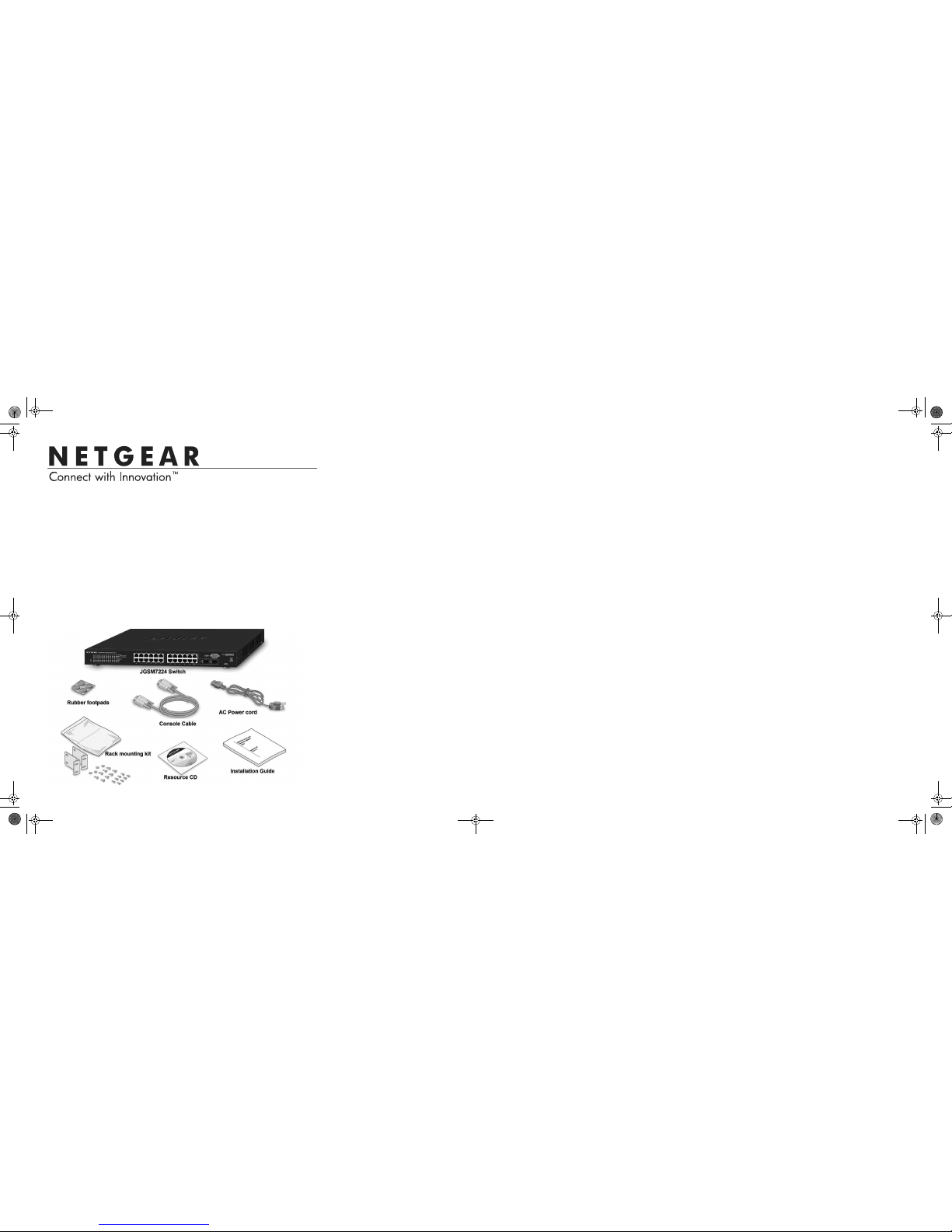
Package Contents
• ProSafe® 24-Port Gigabit Managed Switch JGSM7224
• Rubber footpads for tabletop installation
• Power cord
• Console cable
• Rack-mount kit for installing the switch in a 19-inch rack
• Installation Guide
• Resource CD that includes the JGSM7224 Hardware Installation Guide. (A link
to the online manual is also on the Resource CD.)
Set Up the Switch
Prepare the site so that the mounting, access, power source, and environmental
requirements are met. If you have any questions about these requirements, see the
Hardware Installation Guide for your switch on your Resource CD.
1. Install the switch using one of the following methods:
a. On a flat surface: Put one of the rubber footpads that came with the switch
on each of the four concave spaces on the bottom of the switch.
b. In a Rack: Use the rack-mount kit supplied with your switch, following the
installation instructions included with the kit,.
2. Apply AC power. When you apply power, the power LED can display the
following behavior:
• The power LED will be yellow as it conducts a Power-On Self Test (POST).
After the switch passes the POST, the LED turns green. The switch is now
functional. If the POST fails, the Power LED will remain yellow (see
“Troubleshooting” in the Hardware Installation Manual for assistance).
• If the power LED does not light, check that the power cable is plugged in
correctly and that the power source is good. If this does not resolve the
problem, see “Troubleshooting” in the Hardware Installation Guide.
3. Connect devices to the switch.
• Use Category 5e (Cat5e) for copper ports at 1000Mbps
• Use NETGEAR AGM731F or AGM732F for fiber ports at 1000Mbps..
Note: In the room housing the switch, ensure that the ambient temperature does
not exceed the specified operating temperature and that the environment is free
of water condensation.
Perform the Initial Configuration
This switch can be managed through its Web interface, or by using the Command
Line Interface (CLI) through the serial console port. This guide describes the Web
method. The CLI method is also described to determine a DHCP-assigned IP
address. For Web management, follow one of the following three procedures,
depending upon how your PC is set up.
• PC in DHCP client mode without DHCP server
• PC with static IP address
• PC in DHCP client mode with DHCP server
To perform extensive CLI management, see both the CLI Reference Manual and the
Software Administration Guide for your switch.
PC in DHCP Client Mode without DHCP Server
If no DHCP server is present, the switch assumes a default IP address of
169.254.100.100 and subnet mask of 255.255.0.0. The switch is in the same subnet
used by a PC NIC port when in DHCP-client mode without a DHCP server present.
Use this IP value to log into the switch (see Web Login to the Switch).
PC with Static IP Address
When the PC is in this mode, the switch must also be assigned a static IP address.
To assign a static IP Address, access the switch from the serial console port :
1. Connect a console to the switch.
Using the null-modem cable supplied with the switch, connect a VT100/ANSI
terminal or a workstation to the switch port labeled Console.
2. Start a terminal emulation program (TEP).
a. Start a TEP using the appropriate method for your operating system:
• Windows users can use HyperTerminal.
• Windows Vista users should download a TEP from the Internet.
• Macintosh users can use ZTerm.
• UNIX users can use a terminal emulator such as TIP.
b. Configure the TEP to use the following settings (they are written below the
connector on the switch front panel):
• Baud rate: 9,600 bps
• Data bits: 8
• Parity: none
• Stop bit: 1
• Flow control: none
c. At the command prompt User:, login to the switch using the user name
admin, then press Enter. At the password prompt, type password and
press Enter again. The (JGSM7224)> prompt displays.
JGSM7224 IG 31Aug11.fm Page 1 Wednesday, August 31, 2011 9:39 AM
September 2011
This symbol was placed in accordance with the European Union Directive 2002/96 on the Waste
Electrical and Electronic Equipment (the WEEE Directive). If disposed of within the European Union,
this product should be treated and recycled in accordance with the laws of your jurisdiction
implementing the WEEE Directive.
NETGEAR, the NETGEAR logo, and Connect with Innovation are trademarks and/or registered trademarks of
NETGEAR, Inc. and/or its subsidiaries in the United States and/or other countries. Information is subject to
change without notice. Other brand and product names are registered trademarks or trademarks of their
respective holders. © 2011 NETGEAR, Inc. All rights reserved.
d. The following procedure uses CLI commands to set a static IP address and
subnet mask. Refer to the JGSM7224 CLI Reference Manual for command
descriptions. The IP address used is only an example. End each command
line with Enter.
(JGSM7224) > enable
(JGSM7224) # configure terminal
(JGSM7224) (config)# interface vlanmgmt
(JGSM7224) (config-if)# no ip address
(JGSM7224) (config-if)# ip address 10.10.10.1 255.255.255.0
(JGSM7224) (config-if)# exit
(JGSM7224) (config)# exit
(JGSM7224) # save
Building configuration ...
[OK]
(JGSM7224) #
3. You can now use this IP address to login to the switch through its Web
Management Interface. See Web Login to the Switch.
PC in DHCP Client Mode with DHCP Server
By default, the switch is configured as a DHCP client to obtain its IP address from a
DHCP server in the connected network. You must access the switch from the serial
console port.
1. Make sure that the switch is connected to a DHCP server.
2. Find the switch IP address assigned by the DHCP server.
After locating the switch IP address:
a. Perform steps 1 through 2.c of the procedure PC with Static IP Address.
b. Type the show managment vlan command and press Enter. A screen
will display that shows the active switch IP address.
c. Use this IP address to login to the switch through its Web Management
interface (see Web Login to the Switch).
Web Login to the Switch
Use the appropriate IP address for your configuration to manage your switch
through its Web interface.
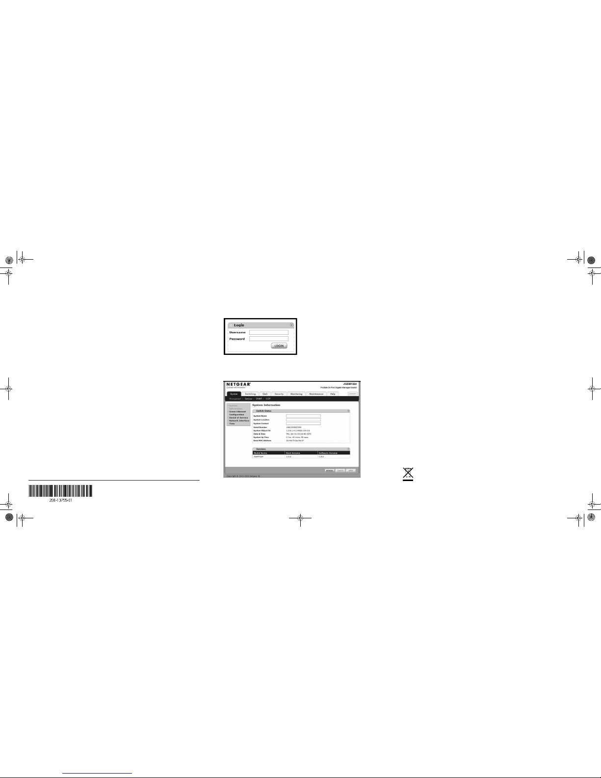
1. Type http://<ipaddress> into the URL window of your browser. A screen
similar to the following, will display.
2. Type admin for the username and password for the password field.
3. Click LOGIN. The Management screen will display. You can now use the
switch menu to configure your switch.
Technical Support
Thank you for selecting NETGEAR products.
After installing your device, locate the serial number on the label of your product and
use it to register your product at http://www.NETGEAR.com/register. Registration is
required before you can use the telephone support service. Registration via our
website is strongly recommended.
Go to http://support.netgear.com for product updates, documentation, and support.
For additional information about setting up, configuring, and using your JGSM7224,
see the User Manual.
For complete DoC please visit the NETGEAR EU Declarations of Conformity
website at: http://support.netgear.com/app/answers/detail/a_id/11621/
For GNU General Public License (GPL) related information, please visit
http://support.netgear.com/app/answers/detail/a_id/2649
WARNING!!
DO NOT stack equipment, or place equipment in tight spaces, or in drawers. Be
sure your equipment is surrounded by at least 2” of air space.
JGSM7224 IG 31Aug11.fm Page 2 Wednesday, August 31, 2011 9:39 AM
 Loading...