

Page 1
SERVICE MANUAL
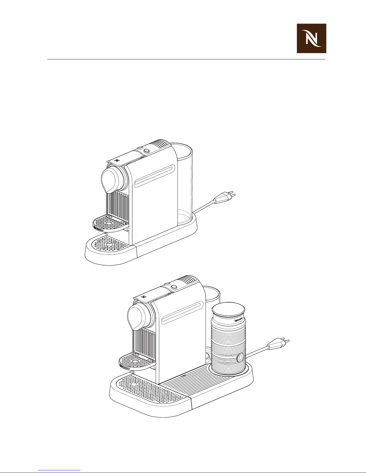
CITIZ REFRESH COFFEE MACHINES
Citiz EF 451 C 111
EF 452 D 111
Citiz & milk EF 467 C 121
EF 468 D 121
Version 1.0 en
Page 2

Citiz service manual
2
CONTENTS
1 General Safety Notes ........................................................................................6
2 Model overview................................................................................................... 7
2.1 Model range ....................................................................................................... 7
2.2 Core unit versions .............................................................................................. 8
3 Main Components..............................................................................................9
3.1 Overview - core unit, D-range ............................................................................ 9
3.1.1 Interior view - core unit, D-range............................................................. 10
3.2 Overview - core unit, C-range .......................................................................... 11
3.2.1 Interior view - core unit, C-range............................................................. 12
3.3 Overview - model Citiz ..................................................................................... 13
3.4 Overview - model Citiz & milk .......................................................................... 14
3.4.1 Overview - milk frother AERO3............................................................... 15
3.5 Fluid System .................................................................................................... 16
3.5.1 Water circuit diagram of core unit (all Citiz versions) .............................. 16
3.5.2 Water circuit of models Citiz/Citiz & milk................................................. 17
4 Technical Data...................................................................................................18
4.1 Rating plates .................................................................................................... 18
4.1.1 Examples of brand specific rating plates ................................................18
4.1.2 Rating plate details ................................................................................. 21
4.1.3 Rating plate of milk frother (EUR-Version model Citiz & milk) ................22
4.1.4 Rating plate of milk frother (USA-Version model Citiz & milk) ................22
4.2 Summary of technical data............................................................................... 23
4.2.1 Technical data of coffee machines.......................................................... 23
4.2.2 Technical data of milk frother (model Citiz & milk) ..................................24
4.2.3 Dimensions and weight - model Citiz...................................................... 25
4.2.4 Dimensions and weight - model Citiz & milk ........................................... 26
4.2.5 Dimensions and weight - milk frother...................................................... 26
5 Operation............................................................................................................27
5.1 General information.......................................................................................... 27
5.2 Status indication............................................................................................... 27
5.2.1 Status indication of coffee machine ........................................................ 27
5.2.2 Status indication of milk frother AERO3..................................................29
5.3 Machine modes................................................................................................ 30
5.3.1 Machine modes of Citiz coffee machines ............................................... 30
5.3.2 Machine modes of milk frother AERO3................................................... 31
5.4 Program/reset fill up level................................................................................. 32
5.4.1 Programming the fill up level...................................................................32
5.4.2 Resetting the fill up level ......................................................................... 33
5.5 Empty water system......................................................................................... 34
6 Maintenance...................................................................................................... 35
6.1 Daily maintenance and cleaning ...................................................................... 35
6.1.1 Before first coffee or at the start of day................................................... 35
Page 3

Citiz service manual
3
6.1.2 Milk preparation ...................................................................................... 36
6.1.3 At the end of repair ................................................................................. 37
6.1.4 Milk frother of model Citiz & milk ............................................................ 38
6.2 Descaling ......................................................................................................... 39
6.2.1 Descaling procedure for models Citiz and Citiz & milk ........................... 39
7 Troubleshooting............................................................................................... 42
7.1 Check list for coffee machine (all models) ....................................................... 42
7.2 Check list for milk frother ................................................................................. 44
8Repairs................................................................................................................ 45
8.1 Safety instructions ........................................................................................... 45
8.2 Repair and mounting tips ................................................................................. 45
8.3 Tools and accessories ..................................................................................... 47
8.4 Platform disassembly - model Citiz.................................................................. 48
8.4.1 General disassembly .............................................................................. 48
8.4.2 Replacing water tank connector ............................................................. 51
8.4.3 Replacing power cord ............................................................................. 53
8.4.4 Removing core unit................................................................................. 55
8.5 Platform disassembly - model Citiz & milk ....................................................... 58
8.5.1 General disassembly .............................................................................. 58
8.5.2 Replacing water tank connector ............................................................. 62
8.5.3 Replacing milk frother connector ............................................................ 64
8.5.4 Replacing power cord ............................................................................. 65
8.5.5 Removing core unit................................................................................. 67
8.6 Disassembly of core unit, C-range................................................................... 70
8.6.1 General disassembly .............................................................................. 70
8.6.2 Replacing compact brewing unit............................................................. 75
8.6.3 Replacing pump...................................................................................... 77
8.6.4 Replacing flow meter .............................................................................. 80
8.6.5 Replacing automatic priming device (APD) ............................................ 81
8.6.6 Replacing thermoblock with NTC sensor and fine wire fuse(s) .............. 83
8.6.7 Replacing electronic control board with button prints ............................. 86
8.7 Disassembly of core unit, D-range................................................................... 88
8.7.1 General disassembly .............................................................................. 88
8.7.2 Replacing electronic control board with button prints ............................. 95
8.8 Wiring diagrams ............................................................................................... 97
8.8.1 Wiring diagrams - model Citiz................................................................. 97
9 Function tests................................................................................................. 101
9.1 Safety instructions ......................................................................................... 101
9.2 Required equipment ...................................................................................... 101
9.2.1 Overview............................................................................................... 101
9.2.2 Citiz pressure gauge adapter ............................................................... 102
9.3 Measure flow rate .......................................................................................... 103
9.4 Pressure and leakage checks........................................................................ 104
9.4.1 Preparations ......................................................................................... 105
9.4.2 Test run................................................................................................. 106
9.5 Measure coffee temperature.......................................................................... 107
Page 4

Citiz service manual
4
9.6 Milk frother tests............................................................................................. 109
9.6.1 Measure hot milk temperature ..............................................................109
9.6.2 Measure milk froth ratio ........................................................................ 109
9.7 Protective earth (PE) continuity test............................................................... 110
9.7.1 What coffee machine has to be tested and when? ............................... 110
9.7.2 General ................................................................................................. 110
9.7.3 Test sequence....................................................................................... 111
9.7.4 What to do if the protective earth continuity test fails............................ 112
9.8 Protective insulation test ................................................................................ 113
9.8.1 What coffee machines have to be tested and when? ........................... 113
9.8.2 General ................................................................................................. 113
9.8.3 Test sequence....................................................................................... 114
9.8.4 What to do if the insulation test fails ..................................................... 116
10 Explosion Drawings ...................................................................................... 117
10.1 Model Citiz EF 451 C111................................................................................ 117
10.2 Parts List EF 451 C111................................................................................... 119
10.3 Model Citiz EF 452 D111................................................................................ 121
10.4 Parts List EF 452 D111................................................................................... 123
10.5 Model Citiz EF 467 C121 ............................................................................... 125
10.6 Parts List EF 467 C121 .................................................................................. 127
10.7 Model Citiz EF 468 D121 ............................................................................... 129
10.8 Parts List EF 468 D121 .................................................................................. 131
Page 5

Citiz service manual
5
PREFACE
The purpose of this service manual is to provide the service personnel with all necessary
information with regards to correct handling, maintenance and repair of the Citiz coffee
machine types EF 451 C 111 / EF 452 D 111 and EF 467 C121 / EF 468 D 121.
This manual should be used by the technicians as a valuable aid to guarantee the
permanent readiness for use of the machines. In order to take full advantage of all the
functions, it is absolutely necessary to follow the instructions in this manual.
For fast access to information directly from the PC or MAC monitor, this service manual
is available as PDF file and can be downloaded from the Nespresso technical website
under https://business.nespresso.com.
The required utility software to read PDF files (Adobe Reader
®
) for PCs and MAC
computers can be downloaded (under http://www.adobe.com) for free - please click the
logo:
CONTENT UPDATES
Version 1.0
• First released service manual version in English.
Please keep this
manual together with
the corresponding
service documentation.
This way you are assured
to have the necessary
information.
The version number
of this service manual
is printed on the lower
right corner of the front
page.
Page 6
Citiz service manual
6
GENERAL SAFETY NOTES
1 GENERAL SAFETY NOTES
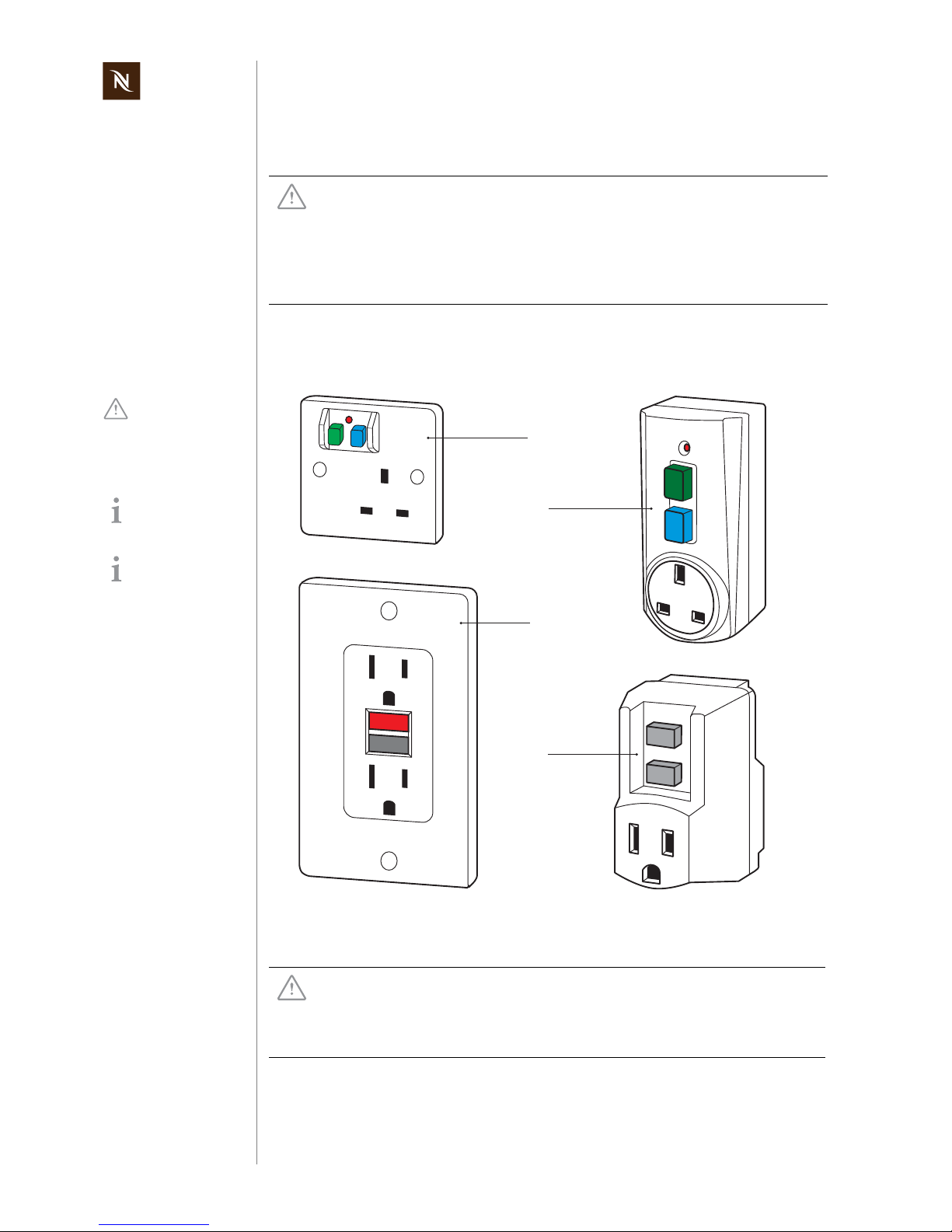
As an additional safety measure, the use of a residual current device (RCD), also called
the ground fault circuit interrupter (GFCI), in the repair centre is highly recommended.
Risk of fatal electrical shock and fire!
Mains voltage inside the coffee machine.
• Unplug appliance before cleaning.
• Never clean wet or immerse plug, cord or appliance in any fluid.
• Disconnect the mains plug before disassembly - the appliance must
be free of voltage.
This device does
not protect against
electrical shock due
to contact with both circuit conductors.
Example illustrations
of typical devices.
Use a GFCI with a trip
level of 4 - 6 mA (USA)
resp. a RCD with a trip
level of 15 - 30 mA (Europe).
A trip level above 30 mA
provides only very limited
protection against harm
from an electric shock.
1) RCD protected socket-outlet
2) Plug-in RCD unit
3) GFCI socket
4) Plug-in GFCI
Danger of burns!
Hot parts and water under pressure inside the coffee machine
(particularly in the thermoblock).
• Let coffee machine cool down before cleaning or disassembly.
1
2
RESET
TEST
RESET
TEST
3
4
Page 7
Citiz service manual
7
MODEL OVERVIEW
2 MODEL OVERVIEW
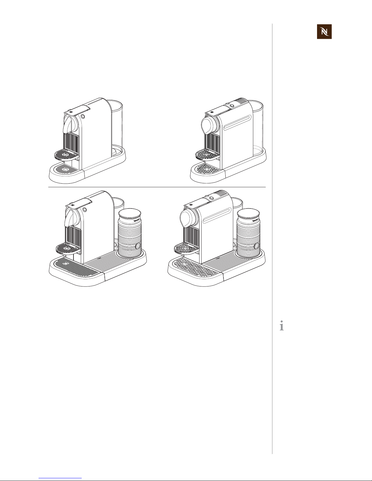
2.1 Model range
With core unit D-range: With core unit C-range:
Each model
- has a special platform
- is available in 2 different designs, depending on the core unit version (C- or D-range).
1) Citiz
2) Citiz & milk
1
2
EF 452 D111
EF 468 D121
EF 451 C111
EF 467 C121
A core unit is the
actual coffee
machine, mounted on
a platform.
Page 8
Citiz service manual
8
MODEL OVERVIEW
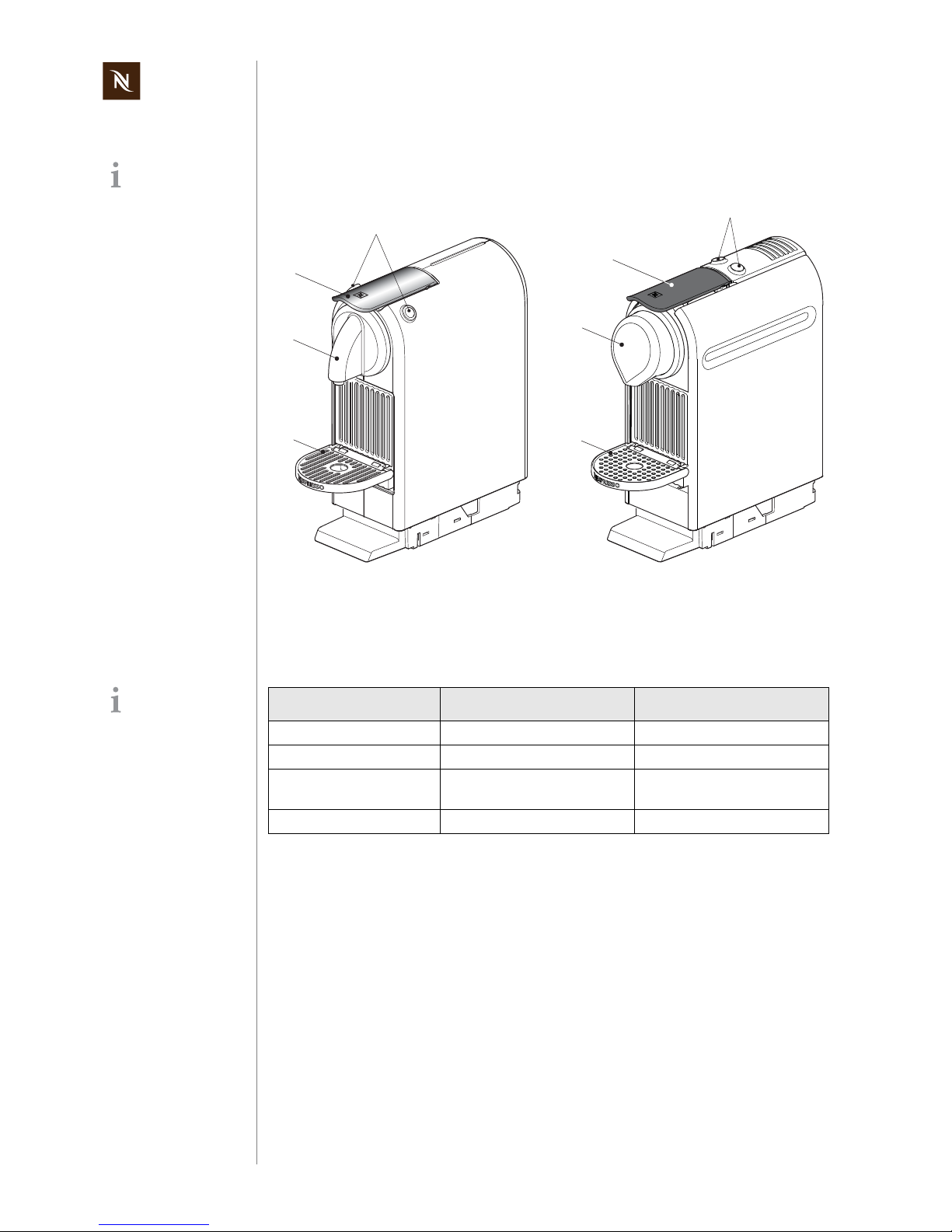
2.2 Core unit versions
D-range C-range
This comparison
helps to identify the
core unit version.
1) Coffee outlet
2) Closing handle
3) Coffee buttons
4) Cup holder
1
1
2
2
3
3
4
4
There are additional
differences between
the 2 versions (covers, wiring etc.) not mentioned in the table.
Different components D-range C-range
Coffee outlet (1) contured coffee outlet "flat" coffee outlet
Closing handle (2) chromium-plated closing handle black closing handle
Coffee buttons (3)
arranged on both sides of the
closing handle
arranged behind the closing
handle
Cup holder (4) cup holder with slotted recesses cup holder with circular recesses
Page 9
Citiz service manual
9
MAIN COMPONENTS
3 MAIN COMPONENTS
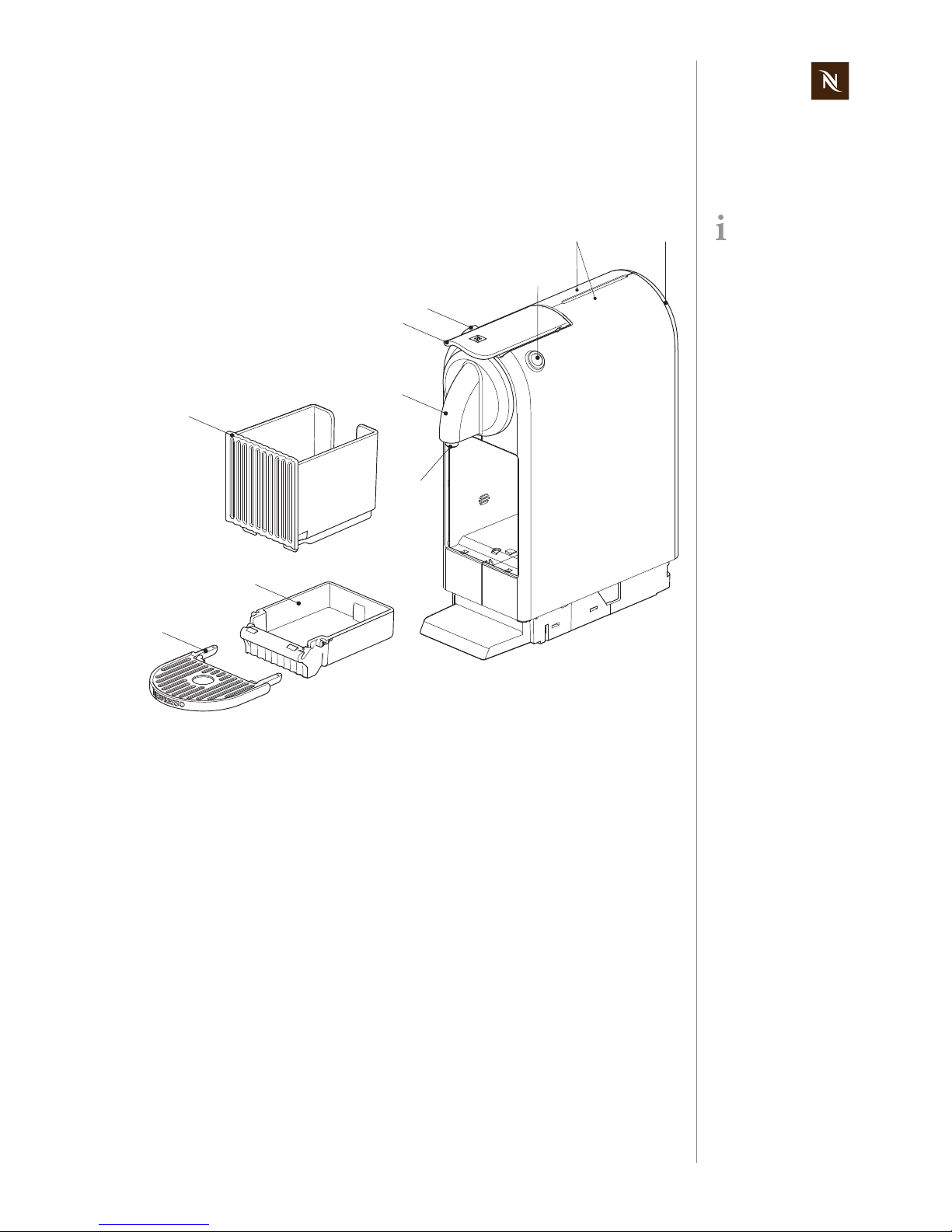
3.1 Overview - core unit, D-range
For platform components refer to model
overview.
1) Cup support
2) Waste water container
3) Capsule container (used capsules)
4) Coffee nozzle
5) Steam cover
6) Closing handle
7) Espresso button
8) Lungo button
9) Side panels left/right
10) Rear cover
3
9
7
5
1
2
6
4
8
10
Page 10
Citiz service manual
10
MAIN COMPONENTS
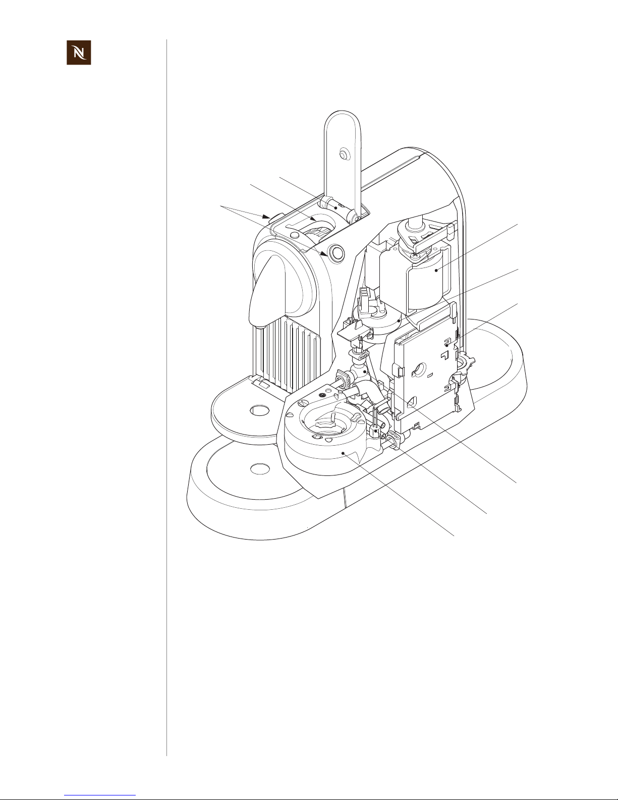
3.1.1 Interior view - core unit, D-range
1) Button prints
2) Capsule bay
3) Brewing unit (TMBU, Tolkien Mini
Brewing Unit)
4) Pump (Sysko)
5) Flowmeter (FHKSC12)
6) Electronic control board
(with protective covers)
7) Self priming device (APD)
8) NTC temperature sensor
9) Thermoblock (EF 2003)
1
2
6
4
5
3
9
7
8
Page 11

Citiz service manual
11
MAIN COMPONENTS
3.2 Overview - core unit, C-range
1) Cup support
2) Waste water container
3) Capsule container (used capsules)
4) Side panel, left
5) Side panel, right
6) Coffee nozzle
7) Steam cover
8) Closing handle
9) Espresso button
10) Lungo button
11) Top cover
12) Rear cover
3
9
7
8
6
10
12
11
4
5
1
2
Page 12

Citiz service manual
12
MAIN COMPONENTS
3.2.1 Interior view - core unit, C-range
1) Capsule bay
2) Brewing unit (TMBU, Tolkien Mini
Brewing Unit)
3) Button prints (under top cover)
4) Pump (Sysko)
5) Flowmeter (FHKSC12)
6) Electronic control board
(with protective covers)
7) Self priming device (APD)
8) NTC temperature sensor
9) Thermoblock (EF 2003)
3
1
6
4
5
2
9
7
8
Page 13
Citiz service manual
13
MAIN COMPONENTS
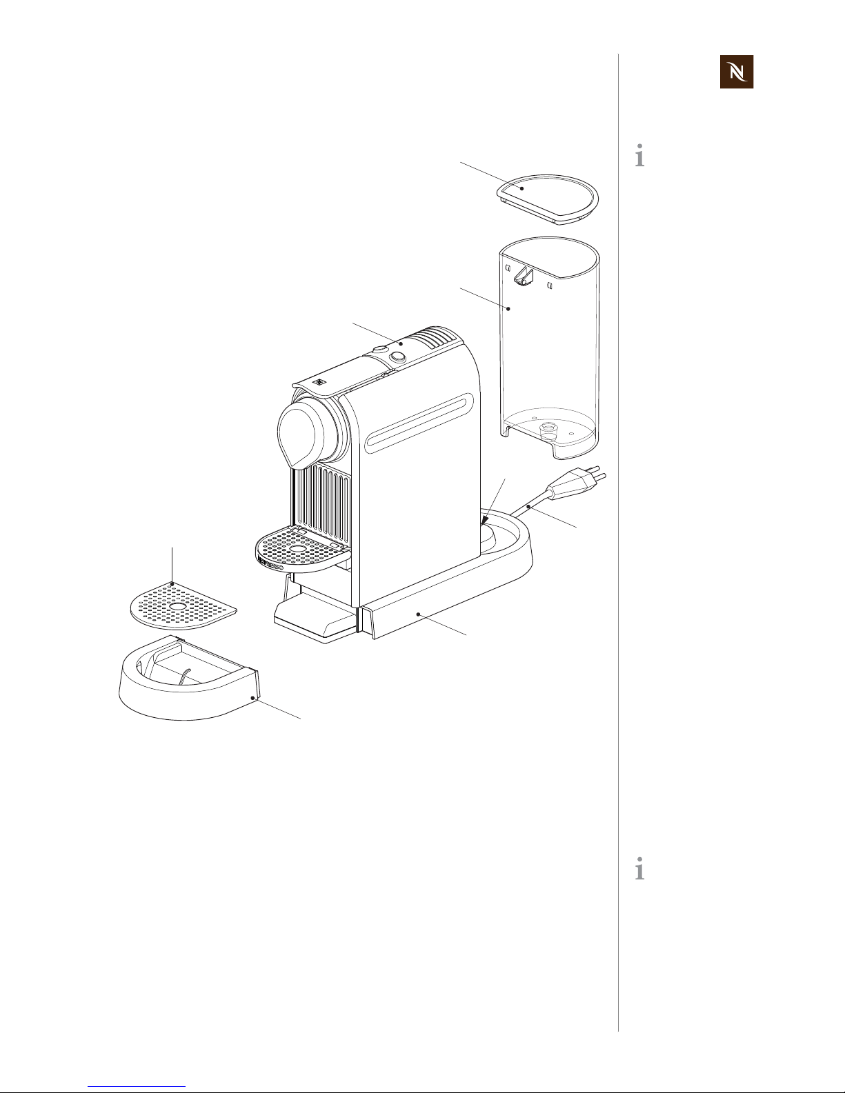
3.3 Overview - model Citiz
This is the basic model with the smallest platform (8).
The drip grid (1)
- exists in 2 versions,
- matches with the cup holder of the core unit version (e.g. circular recesses).
This model is pictured
with a C-range core
unit.
1) Drip grid
2) Drip tray
3) Core unit (e.g. C-range)
4) Water tank cover
5) Water tank
6) Water tank connector
7) Power cord
8) Platform
4
5
1
8
2
7
3
6
The core units of
model Citiz and Citiz
& milk are not compatible due to different
electronic control boards.
Page 14
Citiz service manual
14
MAIN COMPONENTS
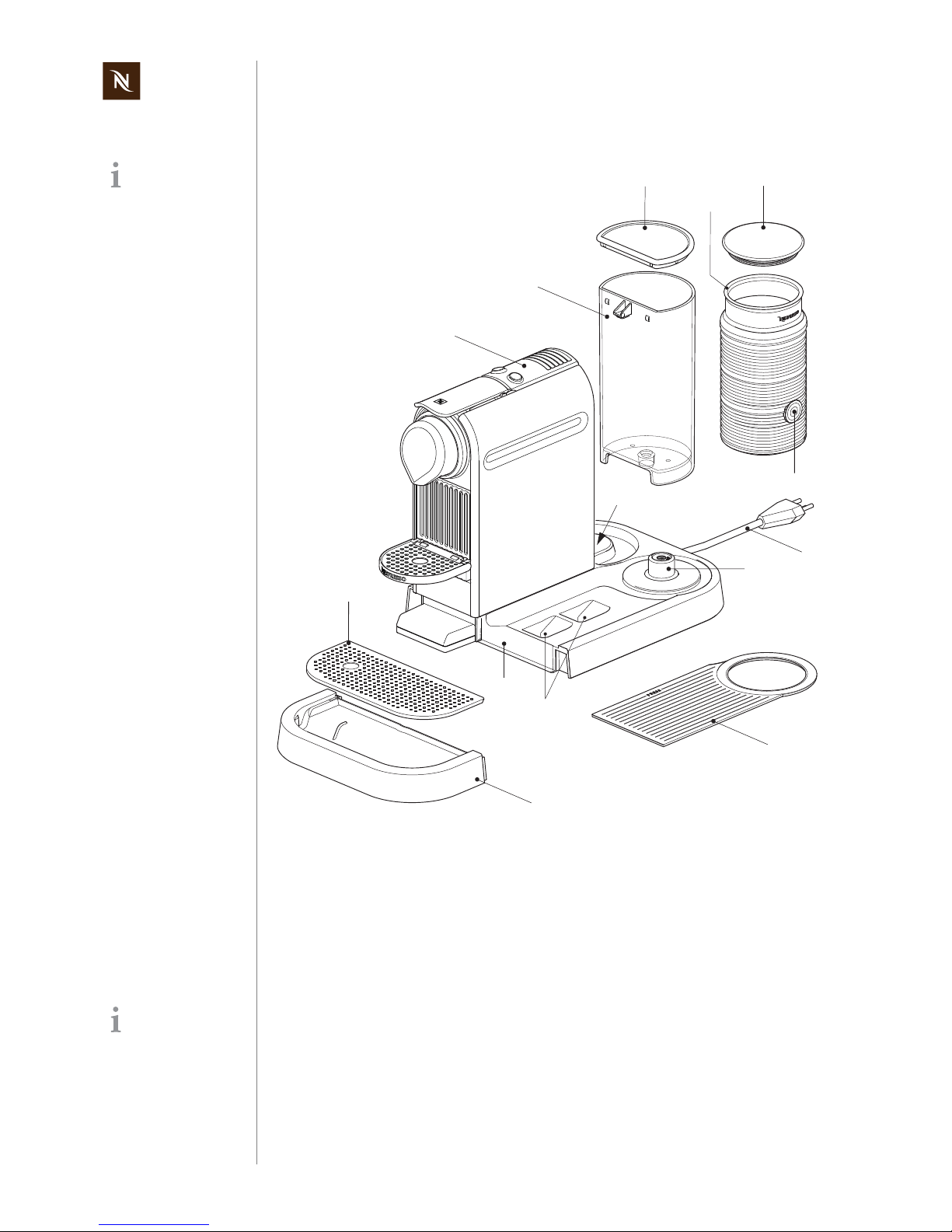
3.4 Overview - model Citiz & milk
The platform of this model is equipped with a milk frother (8).
The drip grid (1)
- exists in 2 versions,
- matches with the cup holder of the core unit version (e.g. circular recesses).
This model is pictured
with a C-range core
unit.
1) Drip grid
2) Drip tray
3) Platform
4) Storage places for whisks
5) Core unit (e.g. C-range)
6) Water tank
7) Water tank cover
8) Milk frother (Aero 3)
9) Lid
10) Milk frother start button
11) Water tank connector
12) Power cord
13) Milk frother connector
14) Cup storage (removable)
6
1
13
2
12
14
7
9
5
8
11
4
10
3
The core units of
model Citiz and Citiz
& milk are not compatible due to different
electronic control boards.
Page 15
Citiz service manual
15
MAIN COMPONENTS
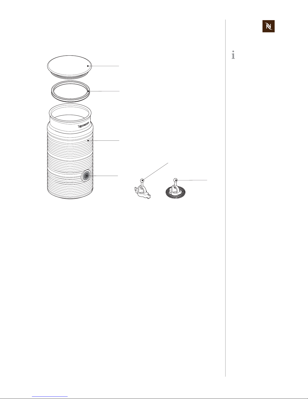
3.4.1 Overview - milk frother AERO3
The inside of the jug (3)
- has level marks,
- is surface-coated for easy cleaning.
The milk frother
AERO3 is part of the
standard equipment
of the model Citiz & milk.
1) Lid
2) Seal
3) Jug
4) Start button (red/blue backlighted)
5) Mixer for hot milk
6) Spring whisk for milk foam
1
2
3
4
6
5
Page 16
Citiz service manual
16
MAIN COMPONENTS
3.5 Fluid System
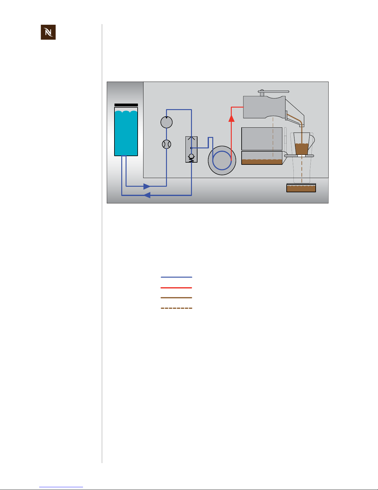
3.5.1 Water circuit diagram of core unit (all Citiz versions)
Legend:
The self priming device (4)
- allows the pump to suck water when it is filled with air (new machine, empty water
tank etc.)
- removes air bubbles from the water circuit
- feeds a water/air mix back into the water tank.
1) Water tank
2) Flow meter
3) Pump
4) Self priming device
5) Thermoblock
6) Mini brewing unit (MBU)
7) Capsule container
8) Waste water container
9) Drip tray
Fresh cold water
Fresh hot water
Coffee
Waste/drip water
Platform
Core unit
APD
TB
MBU
1
3
2
4
5
6
7
8
9
Page 17
Citiz service manual
17
MAIN COMPONENTS
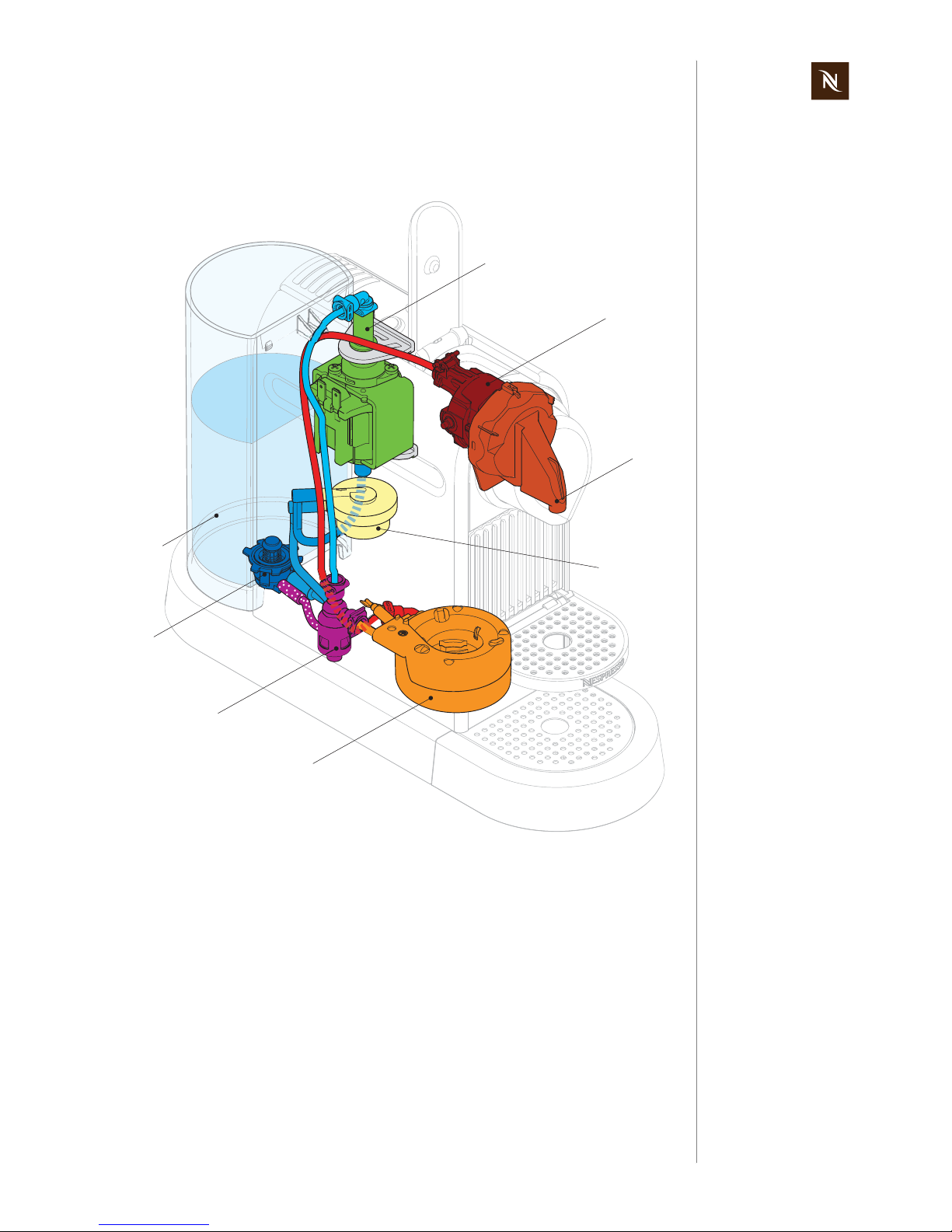
3.5.2 Water circuit of models Citiz/Citiz & milk
1) Water tank
2) Water tank connector
3) APD
4) Thermoblock
5) Flowmeter
6) Outlet
7) Mini brewing unit (MBU)
1
2
3
4
6
5
7
8
Page 18
Citiz service manual
18
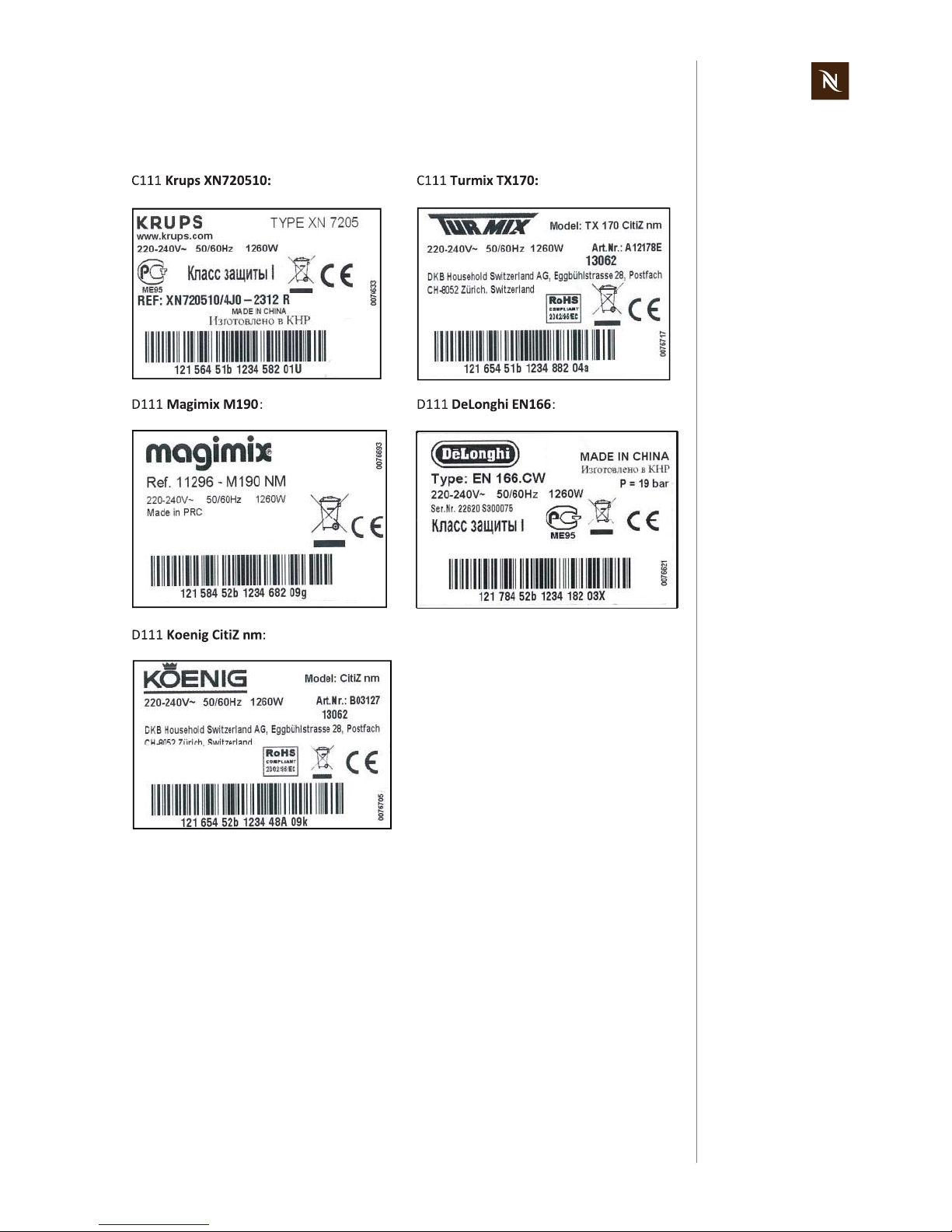
TECHNICAL DATA
4 TECHNICAL DATA
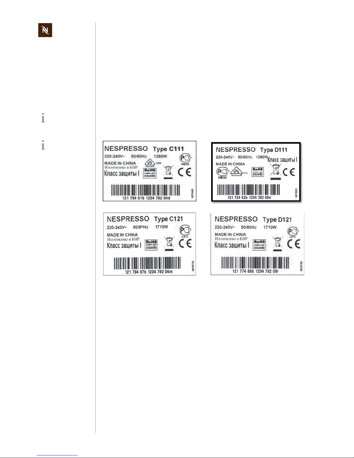
4.1 Rating plates
4.1.1 Examples of brand specific rating plates
Nespresso, EU-version
1) Water tank
2) Water tank connector
3) Self priming device
4) Thermoblock
5) Flow meter
6) Coffee outlet
7) Brewing unit
8) Pump
The type plate can be
found at the bottom of
the coffee machine’s
platform.
This overview shows
examples of various
brands and is subject
to alterations.
EF451 Citiz C111 titan EF452 Citiz D111 black
EF467 Citiz & milk C121 titan EF467 Citiz & milk D121 black
Page 19
Citiz service manual
19
TECHNICAL DATA
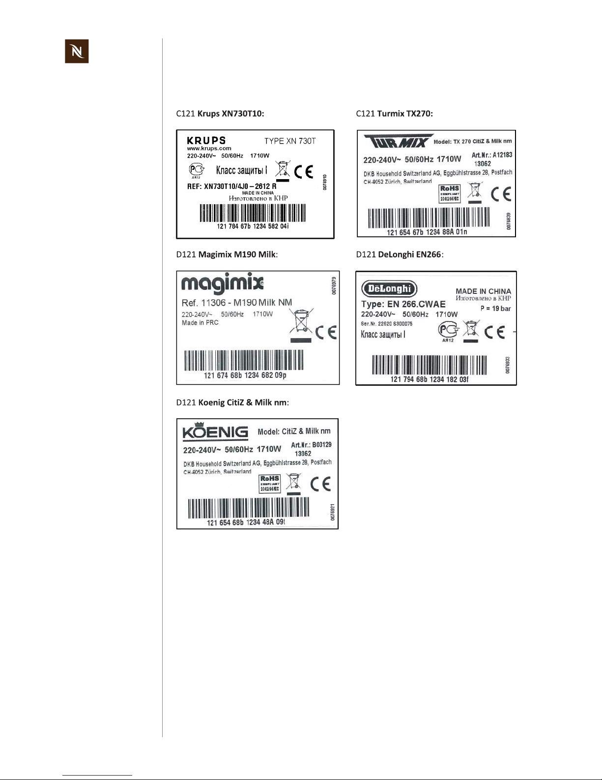
Rating plates Citiz machine partners
Page 20
Citiz service manual
20
TECHNICAL DATA
Rating plates Citiz & milk machine partners
Page 21
Citiz service manual
21
TECHNICAL DATA
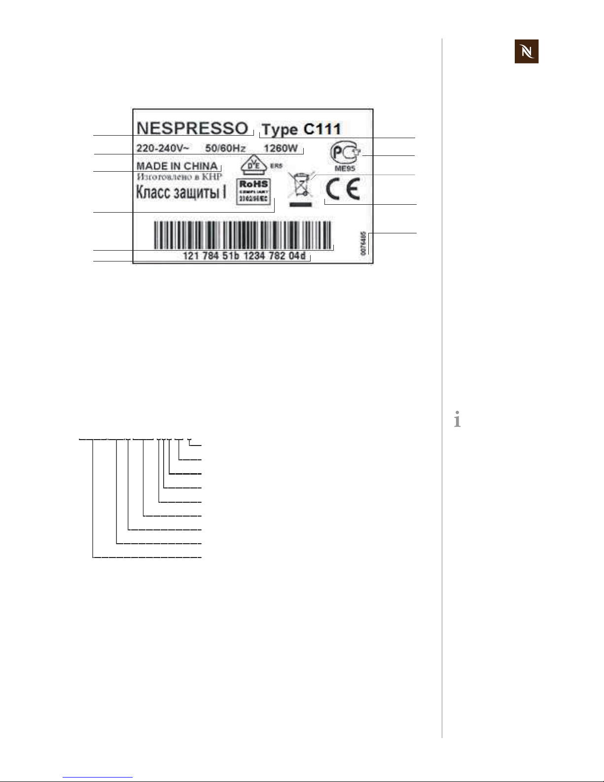
4.1.2 Rating plate details
Decoding the alphanumeric serial number
Example:
1) Brand name
2) Voltage and power rating
3) Place of manufacture
4) National approval sign of Germany
(VDE), conform with RoHS guidelines
(lead free solder, etc.)
5) Barcode
6) Serial number
7) Machine type
8) National approval sign of Russia
(GOST R)
9) Special disposal icon
(do not dispose with ordinary waste)(
10) Sign of conformity (CE)
11) Article number of the rating plate
1
2
3
4
6
5
7
10
11
9
8
By decoding the date
of production and
machine type, the
coffee machine can be
identified exactly.
Checksum (if available)
Colour version
Type of mains plug
Mains voltage
Distributing partner
Incremental number per production day
Manufacturing plant
Manufacturer designation of the machine type (EF 451)
12178 ... Date of production
(12 = year 2012, 178 = 178
th
day of the year)
121 784 51b 1234 782 04 d
Page 22
Citiz service manual
22
TECHNICAL DATA
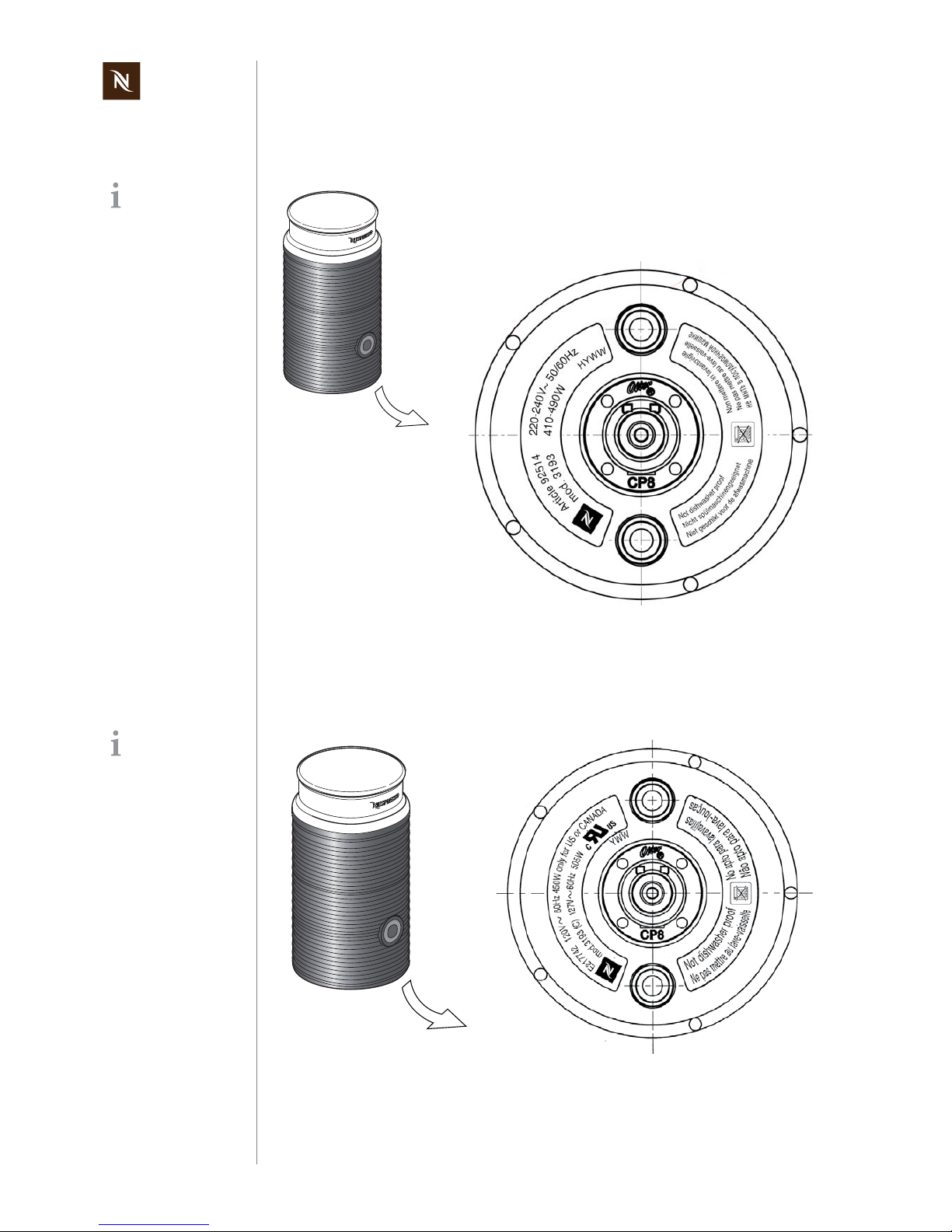
4.1.3 Rating plate of milk frother (EUR-Version model
Citiz & milk)
4.1.4 Rating plate of milk frother (USA-Version model
Citiz & milk)
Note he mains voltage ranges of the different models.
Note he mains voltage ranges of the different models.
Page 23

Citiz service manual
23
TECHNICAL DATA
4.2 Summary of technical data
4.2.1 Technical data of coffee machines
Mains voltage ranges
EU, RU, AU ................................................................................. 220-240 V / 50-60 Hz
US, CA ......................................................................................... 120-127 V / 50-60 Hz
Approvals .................................................................................. CE, Gost R, Ctick, UL
Power ratings of coffee machine main components
(for all voltages and frequencies)
Thermoblock ...................................................................................................... 1200 W
Pump................................................................................................................. 55/65 W
Ratings
Energy efficiency class level for Citiz, Citiz & milk .............................................A - 40%
Daily energy consumption Citiz......................................................................... 73.7 Wh
Daily energy consumption Citiz & milk .............................................................. 75.6 Wh
Annual energy consumption Citiz.................................................................... 26.9 kWh
Annual energy consumption Citiz & milk......................................................... 27.6 kWh
Pump
Pump pressure
- Max. permissible .............................................................................. 17.5 bar ± 1.5 bar
- During coffee preparation (depending on the type of coffee).......................... 9-16 bar
Flow performance ..................................................................120-240 ml/min. at 12 bar
Capacities
Water tank
- Citiz........................................................................................................................1.0 l
- Citiz & milk .............................................................................................................1.0 l
Drip tray
- Citiz.................................................................................................................... 100 ml
- Citiz & milk .........................................................................................................180 ml
Capsule container
- Citiz, Citiz & milk .....................................................................................9-11 capsules
Technical data are
valid for all Citiz models unless explicitly
stated otherwise.
Advised water tank
capacities to avoid
spilling.
Page 24

Citiz service manual
24
TECHNICAL DATA
Temperatures
Operating temperature ................................................................... + 5 °C up to + 45 °C
Storage temperature...................................................................... - 25 °C up to + 60 °C
Safety temperature (thermal cut-off) ................................................................... 167 °C
Coffee temperature at outlet....................................................................... 86 °C ± 3 °C
Various data
Preheating time .......................................................................................approx. 25 sec
Cable length .............................................................................................. approx. 1.0m
4.2.2 Technical data of milk frother (model Citiz & milk)
Mains voltage
EU ............................................................................................... 220-240 V / 50-60 Hz
US/CA .......................................................................................... 120-127 V / 50-60 Hz
The milk frother
- is available in 2 different models, depending on above mains voltage ranges,
- has to match the mains voltage range of the associated coffee machine.
Capacity
Hot milk ...................................................................................................... max. 240 ml
Hot/cold milk for milk froth ...........................................................................max. 130 ml
Performance data
Preparation times
(with full, semi-skimmed or skimmed milk at 8 °-10 °C fridge temperature)
Hot milk froth (120 ml) .....................................................................................50-80 sec
Cold milk froth (120 ml) ...................................................................................60-80 sec
Hot milk (240 ml) .........................................................................................120-180 sec
Temperature
Hot milk ............................................................................................. + 60 °C to + 70 °C
Foam milk.......................................................................................... + 60 °C to + 70 °C
If replacing a defect
milk frother, check
mains voltage range.
Page 25

Citiz service manual
25
TECHNICAL DATA
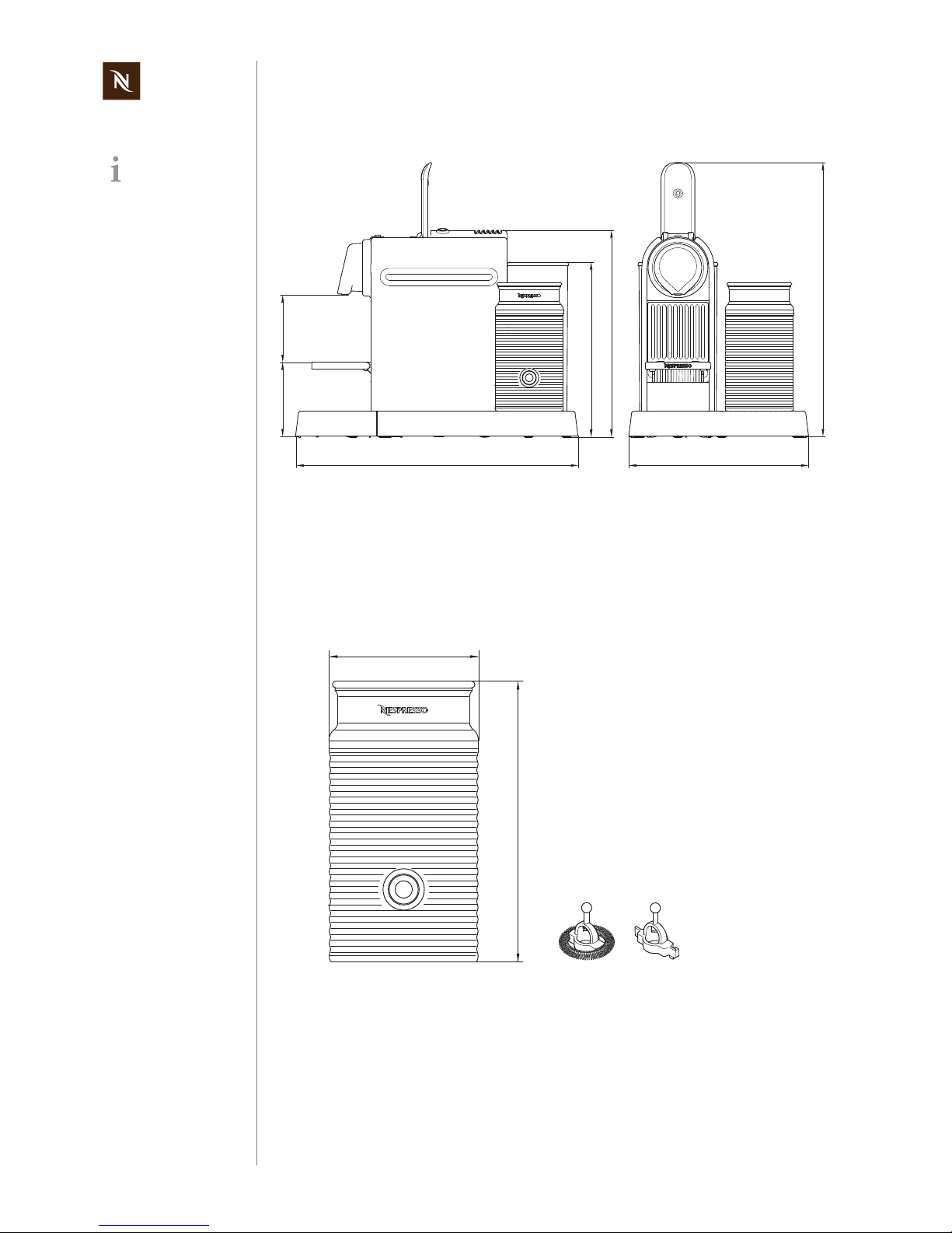
4.2.3 Dimensions and weight - model Citiz
Dimensions (width x height x length) ............................................ 130 x 277 x 372 mm
Cup support down ...............................85-90 mm, for espresso and lungo cups/glasses
Cup support up ...................................................... 150-155 mm, for macchiato glasses
Weight (without water) ............................................................................. approx. 3.4 kg
The overall dimensions are the same
for both core unit ver-
sions (C- and D-range).
Dimensions in mm
89
98
372
130
361
230
277
Page 26
Citiz service manual
26
TECHNICAL DATA
4.2.4 Dimensions and weight - model Citiz & milk
Dimensions (width x height x length)............................................. 237 x 277 x 372 mm
Weight (without water, milk frother included)............................................approx. 4.6 kg
4.2.5 Dimensions and weight - milk frother
Dimensions of jug cpl. (diameter x height) ................................................ 91 x 170 mm
Whisk for foam (diameter x height) ..............................................................33 x 32 mm
Mixer for hot milk ..................................................................................15 x 34 x 32 mm
Weight (with whisk and mixer)...............................................................................0.7 kg
The overall dimensions are the same
for both core unit ver-
sions (C- and D-range).
Dimensions in mm
361
89
97.5
237372
231
277
Ø91
170
Page 27
Citiz service manual
27
OPERATION
5 OPERATION
5.1 General information
For an overview of operational controls see “Main Components” on page 9.
For basic operation of the machine such as preparing a coffee and other related infor-
mation, refer to the user manual.
To simplify matters, the model Citiz with core unit C-range is used to exemplify throughout
this chapter.
5.2 Status indication
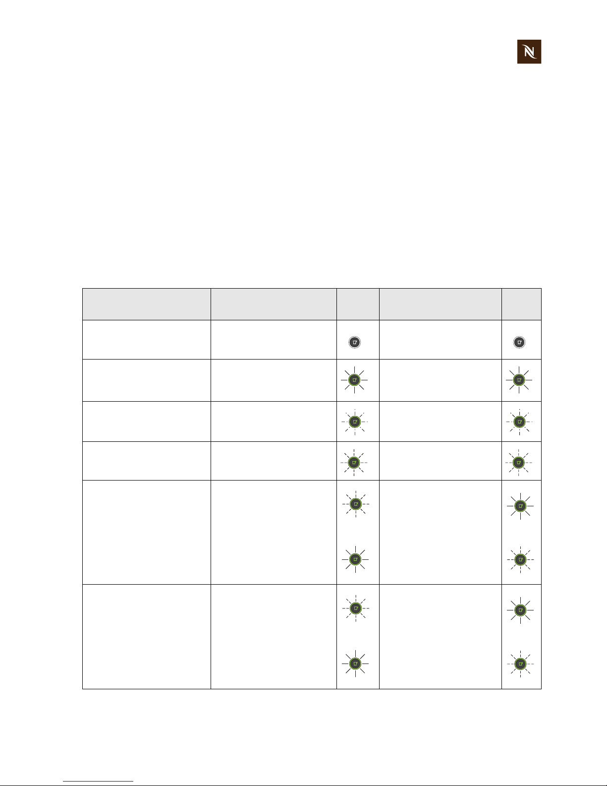
5.2.1 Status indication of coffee machine
The two coffee buttons with green LED backlight show the status of the coffee machine
according to the following table:
Operating mode Small cup
Led
signal
Big cup
LED
signal
Off Off Off
Ready On On
Error
Blinking fast 3 times
every 2 sec.
Blinking fast 3 times
every 2 sec
Heat up
Blinking slow 1 Hz,
0.25sec on / 0.5sec off
Blinking slow 1 Hz,
0.25sec on / 0.5sec off
Brewing small cup
Brewing big cup
Blinking slow 1 Hz,
0.25sec on / 0.5sec off
On
On
Blinking slow 1 Hz,
0.25sec on / 0.5sec off
Rinse small cup
Rinse big cup
Blinking slow 1 Hz,
0.25sec on / 0.5sec off
On
On
Blinking slow 1 Hz,
0.25sec on / 0.5sec off
Page 28
Citiz service manual
28
OPERATION
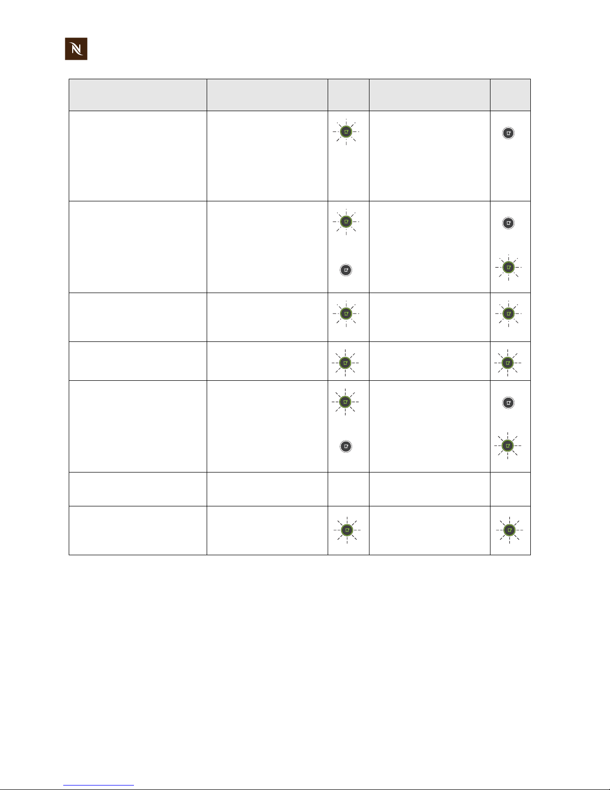
Operating mode Small cup
Led
signal
Big cup
LED
signal
Power off Program
Blinking small cup 2 Hz
in 2sec frame
- 1x for 9 min.
(factory setting)
- 2 x for 30 min.
- 3 x for deactivated
Off
Emptying
Blinking fast 2 Hz,
0.25sec on / 0.5sec off
Off
Off
Blinking fast 2 Hz,
0.25sec on / 0.5sec off
Descaling ready
D. pump on (descal.)
D. pump off (descal.)
Blinking fast 2 Hz,
0.25sec on / 0.5sec of
Blinking fast 2 Hz,
0.25sec on / 0.5sec of
Overheat
Blinking slow 1 Hz,
0.25sec on / 0.5sec off
Blinking slow 1 Hz,
0.25sec on / 0.5sec off
Order small cup (during
heat)
Order big cup (during heat)
Blinking slow 1 Hz,
0.25sec on / 0.5sec off
off
Off
Blinking slow 1 Hz,
0.25sec on / 0.5sec off
No more stand by
No more power save
--
Resetting to factory Blinking 3 Hz Blinking 3 Hz
Page 29
Citiz service manual
29
OPERATION
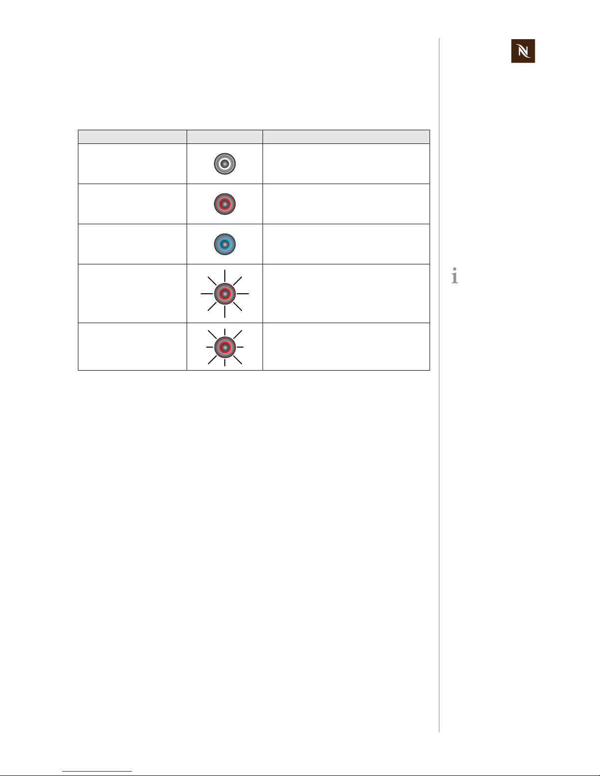
5.2.2 Status indication of milk frother AERO3
The operating button with red/blue backlight shows the status of the milk frother
according to the following table:
To reset a red blinking
backlight:
1. Remove milk frother from
platform.
2. Remove cause of failure if
possible.
Machine status etc. Operating button Light signal
Off Backlight off
On - hot milk preparation Red backlight on
On - cold milk froth preparation
Blue backlight on
Failure/malfunction
(e.g. overheating because of
burnt milk, too less or no
milk)
Blinking red backlight
(1 Hz, 0.5sec on, 0.5sec off)
Failure: milk frother has
wrong mains voltage range
Fast blinking red backlight
(2 Hz, 0.25sec on, 0.25sec off
Page 30

Citiz service manual
30
OPERATION
5.3 Machine modes
5.3.1 Machine modes of Citiz coffee machines
This table helps to understand the operating modes of a Citiz coffee machine:
Machine mode Enter mode Actions Exit mode
1 Heat up mode
Every time after start
the machine
Heats up thermoblock
to ready temperature
90 °C within 60 s without overshooting target
temperature
2 Self test mode
Every time after start
the machine
Tests:
• NTC short circuit
• NTC connected
• Thermoblock hea ting
curve
Error handling:
Tracking of the last 5
errors by a ring buffer
3 Ready mode
• After heat up and self
test mode was ok
• After brewing or
volume brewing
coffee
• After reset mode
• After leaving
descaling mode
Keeps thermoblock
temperature at 90 °C
4a Brewing mode
4b Volume brewing
mode (programming cup size)
• Press and release
lungo or espresso
button (brewing
mode)
• Press and hold lungo
or espresso button
for more than 3 sec
(programming mode)
• Press and release
lungo or espresso
button when
machine was in
brewing mode or
automatic exit given
by the flow meter
• Release lungo or
espresso button
when machine was
in programming
mode
5 Descaling mode
• Start machine, wait
until ready
• Press and hold both
coffee buttons for at
least 3 s
• Regulate temperature to 65 °C (after
pump was started)
• Stop and start pump
with any coffee
button, no volume
brewing in descaling
mode
• Press and hold both
coffee buttons for at
least 3 s
Note:
When machine is
switched off during any
descaling mode, then it
goes to descaling
mode ready state after
next start.
Page 31

Citiz service manual
31
OPERATION
5.3.2 Machine modes of milk frother AERO3
6 Emptying mode
(evaporating)
1) Machine off and
lever closed
2) Press both the
espresso and
lungo buttons for 3
sec
3) Buttons flash alternatively
1) Start pump
2) Stop pump after
10 sec
3) Heat up thermoblock to 105 °C
(100% power)
4) Switch off thermoblock
5) Machine switch off
7 Resetting mode
1) Machine off
2) Press and hold
down the lungo
button for 5 sec
3) Buttons flash fast
3 times and
machine heats up
• Reset the
programmed lungo
and espresso
volumes to factory
setting
• Indicate the resetting
mode for 3 sec
Factory settings:
• small cup .... 40 ml
• large cup ... 110 ml
Proceeds with self test
mode automatically
8 Energy saving mode
To modify the energy
saving mode:
1) Machine in off
mode
2) Press and hold
espresso button
for 3sec
3) Espresso button
blinks to indicate
the current setting:
1x = 9min,
2x = 30min,
3x = deactivated
4) To change the setting, press the
espresso button
until it blinks
according to the
desired setting
• Reduce thermoblock
temperature
• Auto switch off after 9
or 30 min or deactivated
Press the lungo button
for 3 sec to exit the
energy saving mode"
9 Failure mode
Automatically by following failures:
a) NTC short circuit
b) NTC not connected
c) Heat up too slow
Machine indicates failure with coffee button
LED‘s as long as the
failure is present
When failure is fixed
Machine mode Enter mode Actions Exit mode
1 Hot milk / milk froth
preparation
Press start button
briefly
Start button lights up
red. Milk is heated and
mixed.
Automatic switch-off
after preparation
2 Cold milk froth preparation
Keep start button
pressed for approx.
2sec
Start button lights up
blue. Milk is mixed only.
Automatic switch-off
after preparation
Machine mode Enter mode Actions Exit mode
Page 32

Citiz service manual
32
OPERATION
5.4 Program/reset fill up level
Each coffee button can be programmed with a coffee volume for an individual cup size.
The procedure for programming/resetting is the same for both coffee buttons.
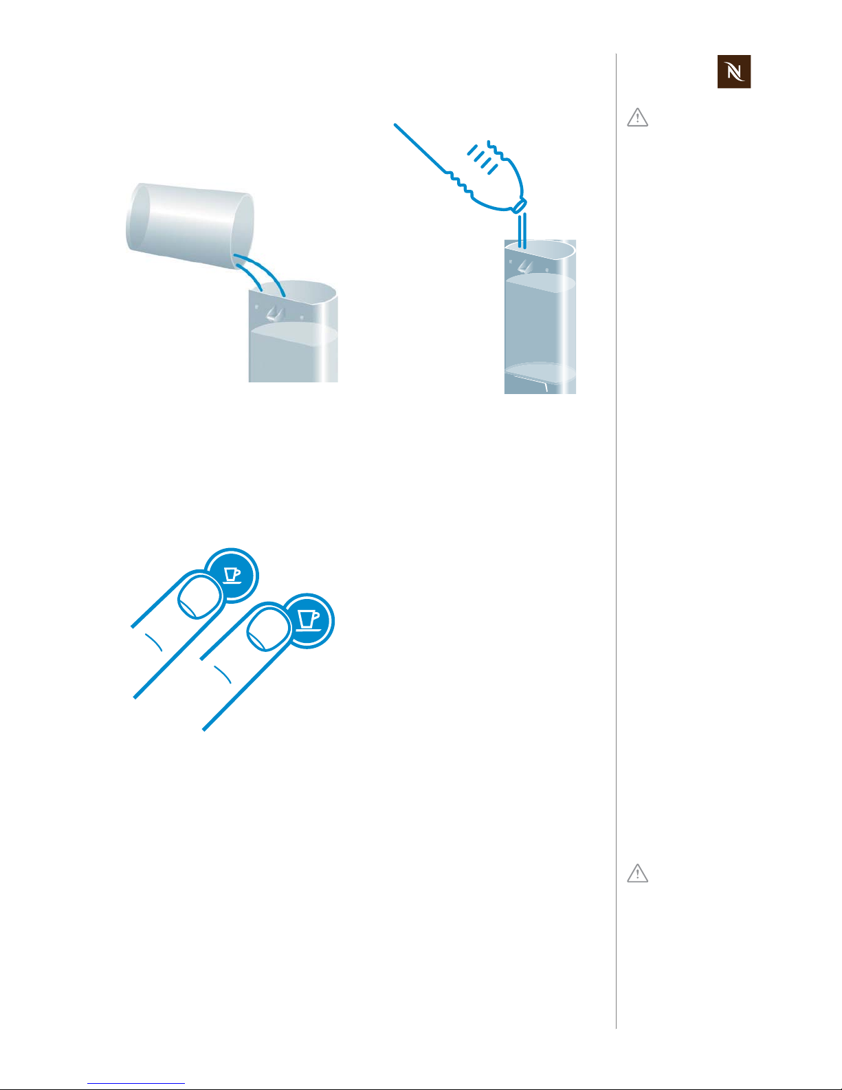
5.4.1 Programming the fill up level
Programmable volume range ........................................................................ 10 - 750 ml
Each new programming cycle starts with
the min. volume
(10 ml after 3 sec), regardless of a preprogrammed
coffee volume.
1) Turn the machine on and wait for it to
be in ready mode (steady lights).
2) Fill the water tank with potable water
and insert a Nespresso capsule.
3) Place a cup under the coffee outlet. 4) Press and hold the espresso or lungo
button.
5) Release button once the desired volume is served.
6) Water volume level is now stored.
2
1
3
4
Page 33

Citiz service manual
33
OPERATION
5.4.2 Resetting the fill up level
With the following procedure all programmed fill up levels will be set back to this factory
settings:
Coffee button "Espresso" ....................................................................................... 40 ml
Coffee button "Lungo" ...........................................................................................110 ml
1) With machine being turned off, press
and hold down the lungo button for
5 seconds.
2) LEDs will blink fast 3 times to confirm
machine has been reset to factory settings.
3) LEDs will then continue to blink normally, as heating up, until ready.
Steady lights: machine ready
Factory settings:
Espresso cup ...................................40 ml
Lungo cup......................................110 ml
Power Off mode...............................9 min
3x
Page 34

Citiz service manual
34
OPERATION
5.5 Empty water system
After every operation, some water remains in the coffee machine. Therefore the water
system must be emptied
- if the coffee machine will not be used for a long time
- as antifreeze measure
- for repairs and shipment.
1) To enter the emptying mode, press
both the espresso and lungo button to
turn the machine off.
2) Remove the water tank and open the
lever.
After this procedure,
the coffee machine
will not be ready for
approx. 10 min (until the
thermoblock cools to below
100 °C).
3) Press both the espresso and lungo
button for 3 seconds.
Both LEDs blink alternatively.
4) Close the lever.
5) Machine switches off automatically.
6) Empty and clean the used capsule
container and drip tray.
Page 35

Citiz service manual
35
MAINTENANCE
6 MAINTENANCE
6.1 Daily maintenance and cleaning
6.1.1 Before first coffee or at the start of day
The Citiz model is
shown as example.
Maintain and clean
other models accordingly
.
1) Rinse then fill the water tank with
potable water.
2) Press the espresso or lungo button to
activate the machine.
Blinking Lights: heating up (25 sec)
Steady Lights: ready
3) Lift the lever completely and insert a
Nespresso capsule.
4) Close the lever and place a cup under
the coffee outlet.
Page 36

Citiz service manual
36
MAINTENANCE
6.1.2 Milk preparation
5) Press the espresso (40 ml) or the
lungo (110 ml) button to start. Preparation will stop automatically. To stop
the coffee flow or top up your coffee,
press again.
6) Remove the cup. Lift and close the
lever to eject the capsule into the used
capsule container.
1) Place milk frother on connector. 2) Attach whisk or mixer; see recipes
section.
1 whisk
1 mixer
Keep connectors
dry (on platform and
at underside of milk
frother).
3) Fill milk frother with desired amount of
milk
4) Press button to start. Lamp lights up.
Milk frother stops automatically.
07.05.12
Fill m
desi
Rem
avec
Page 37

Citiz service manual
37
MAINTENANCE
6.1.3 At the end of repair
Risk of fatal electrical shock and fire!
Never clean wet or immerse plug, cord or appliance in any fluid.
Unplug appliance and let it cool down to avoid burns.
Platform and drip tray
surfaces are not
abrasion-proof.
Never use brushes and/or
cleaning agents that contain aggressive or chemical
components resp. solvents.
Do not put any part in a
dishwasher.
Use only a damp cloth or
sponge and a mild cleaning
agent if necessary.
Do not use a brush -
the water tank can be
scratched.
1) Clean the coffee outlet and the sepa-
rate pieces with a soft damp cloth.
Page 38

Citiz service manual
38
MAINTENANCE
6.1.4 Milk frother of model Citiz & milk
Risk of damage!
The inside of the jug is coated for easy cleaning.
Never use brushes and/or cleaning agents that contain abrasive or
aggressive, chemical components resp. solvents.
Do not put any part in a dishwasher.
Use only a damp cloth and a mild cleaning agent if necessary.
1) Remove milk frother from platform. 2) Remove lid and dismantle whisk.
1.
2.
Keep connectors
dry (on platform and
at underside of milk
frother).
3) Remove seal from lid.
4) Rinse and clean milk frother together
with whisk or mixer, lid and seal.
5) Clean outside of milk frother with a
damp cloth if necessary.
6) Reassemble milk frother.
3.
4.
6.
5.
Page 39

Citiz service manual
39
MAINTENANCE
6.2 Descaling
Use this chart to inform a customer when to descale the coffee machine depending on
local water hardness and average coffee consumption.
This machine is equipped with a descaling alarm. When both LEDs blink during ready
mode, your machine needs descaling.
6.2.1 Descaling procedure for models Citiz and Citiz & milk
Only use Nespresso descaler or descaling kit - never use vinegar!
Descaler can damage casing and contact surfaces.
Immediately clean drops of descaling solution.
The descaling chart is
based on a cup size of
40 ml.
fH ... French grade
dH ... German grade
CaCO3 ... Calcium carbonate
Water hardness:
Descale after:
The Citiz model is
shown as example.
1) Remove the capsule and close the
lever.
2) Empty the drip tray and used capsule
container.
Page 40

Citiz service manual
40
MAINTENANCE
Observe the safety
instructions on the
descaler package.
Use a container with a
capacity of 1 l min.
3) Fill the water tank with 0.5 L of potable
water and add 1 Nespresso descaling
liquid.
4) Place a container (min. volume 1 L)
under the coffee outlet.
5) To enter the descaling mode, while the
machine is turned on, press both the
espresso and lungo button for 3 seconds.
Both LEDs blink.
6) Press the lungo button and wait until
the water tank is empty.
Page 41
Citiz service manual
41
MAINTENANCE
Danger!
Hot splashes of
descaling solution.
Do not open handle during descaling process.
7) Refill the water tank with the used descaling solution collected in the container and repeat step 4 and 6.
8) Empty and rinse the water tank. Fill
with potable water.
9) When ready, repeat step 4 and 6 to
now rinse the machine.
10) To exit the descaling mode, press both
the espresso and lungo button for
3 seconds.
11) The machine is now ready for use.
Danger of injury!
Residual descaler
may be harmful.
Rinse thoroughly to
remove any residue.
Page 42

Citiz service manual
42
TROUBLESHOOTING
7 TROUBLESHOOTING
7.1 Check list for coffee machine (all models)
After an initial inspection in accordance
with this check list,
errors are quickly found and
corrected with the appropriate measure.
Therefore, adhere to the
sequence of the check list.
Repair every occurring error
and work the check list
through until it is completed.
Check Error symptoms
Measure /
repair work
Further measures / repair
work
1 Check the coffee
machine for visible damage
1.1 Housing parts broken or damaged
YES - replace housing parts if
necessary
NO - continue
1.2 Power cord damaged
YES - replace power cord
NO - connect power cord of
machine to the mains and continue
2 Check mechani-
cal components
2.1 Cup support does
not remain in vertical position
YES - check if the capsule and
waste water container are correctly inserted and mounted
NO - continue
YES - replace damaged or
deformed capsule container
and/or waste water container.
2.2 Cup support rattles
when folded down
YES - check if 2 rubber stoppers are mounted on waste
water container
NO - continue
NO - replace stoppers
2.3 Closing handle
malfunction
YES - it is very difficult or
almost impossible to close the
handle and to press it all the
way down
NO - continue
YES - replace the compact
brewing unit
2.4 Closing handle unusual noise during actuation
YES - check if damper is
mounted underneath closing
handle
NO - continue
NO - replace damper
2.5 Capsule is not
ejected correctly
YES - replace brewing unit
(TMBU)
NO - continue
3 Fill water tank 3.1 Water tank leaks
YES - replace water tank
NO - continue
4 Activate Coffee
Machine to perform automatic
self test
4.1 Coffee machine is
not working
(does not function)
a) YES - power cord is okay
(loose connection)
YES - continue
NO - replace power cord
b) YES - pump works (press a
coffee button)
YES - continue with point f)
NO - continue with point c)
c) YES- both coffee buttons are
working
YES - continue
NO - replace electronic control
board
d) YES- pump thermostat is
working
YES - replace thermostat
NO - replace pump
e) YES- fine wire fuse(s)
(167 °C) on thermoblock defective
YES - replace thermoblock and
if necessary replace electronic
control board
NO - continue
f) YES - wiring is okay
NO - continue with point 4.3
YES - replace electronic control board
NO - replace defective cables
4.2 Both coffee buttons
are blinking 3x fast
YES - thermoblock is hot
NO - self test ok - continue
YES - replace NTC temperature sensor
NO - replace thermoblock
Page 43

Citiz service manual
43
TROUBLESHOOTING
5 Measure coffee
temperature during preparation
(see page 107)
5.1 No coffee
YES - a) water system is empty YES - replace self priming
device (APD)
NO - continue
YES - b) flow meter blocked YES - clean or replace
NO - continue
YES - c) pyramid plate clocked YES - replace the compact
brewing unit
NO - continue
YES - d) coffee machine is calcified
NO - continue
YES - descale coffee machine
(see page 39)
5.2 Temperature is too
low (below 83°C)
YES - descale coffee machine
(see page 39)
NO - continue
5.3 Temperature too
high (over 89 °C)
YES - replace NTC temperature sensor
NO - continue
6 Check for leakage
(see page 104)
and measure flow
rate (see page
103)
6.1 Compact brewing
unit leaks
YES - replace compact brewing unit
NO - continue
6.2 Hose connections
leak
YES - replace defective hoses
and seals
NO - continue
6.3 Rate of flow not in
the standard range
YES - coffee machine is calcified
NO - continue with point 9
YES - descale coffee machine
(see page 39)
NO - replace pump
7
Descale coffee
machine
(if necessary)
7.1 Coffee machine is
calcified
YES - descale coffee machine
(see page 39)
NO - continue with point 9
8 Final cleaning
(see page 35)
No errors found according to
check list?
YES - for more information
please contact Nespresso
Service Division
End of check list
Check Error symptoms
Measure /
repair work
Further measures / repair
work
Page 44

Citiz service manual
44
TROUBLESHOOTING
7.2 Check list for milk frother
The milk frother is part
of the Citiz & milk
model.
Check Error symptoms
Measure /
repair work
Further measures / repair
work
1 Check milk frother
and accessory for
visible damage
1.1 Lid/seal broken or
damaged
YES - replace lid/seal
NO - continue
1.3 Whisks broken or
damaged
YES - replace whisks
NO - continue
4 Place milk frother
on platform connector.
Attach whisk.
Switch on coffee
machine.
Press start button
briefly (hot milk
preparation).
4.1 Milk frother is not
working (does not
function)
YES - a) coffee machine is
heating up
YES - continue
NO - continue with check list for
coffee machine
YES - b) connector on platform
is ok (test it with another milk
frother)
YES - replace milk frother
NO - replace connector on platform (see page 64)
4.2 Abnormal noise
during preparation
YES - replace milk frother
NO - continue
4.3 Milk frother does
not switch off automatically
YES - replace milk frother
NO - continue
4.4 Inside of jug stays
cold
YES - replace milk frother
NO - continue
5 Press start button
for at least 2 sec
(cold milk preparation)
5.1 Start button is not
backlighted in blue
YES - replace milk frother
6 Final cleaning
(see page 37)
No errors found according to
check list?
YES - for more information
please contact Nespresso
Service Division
End of check list
Page 45
Citiz service manual
45
REPAIRS
8 REPAIRS
These repair instructions
- are based on exploded drawings with position numbers combined with repair and
mounting tips,
- presuppose basic knowledge in repairing Nespresso coffee machines.
As a rule, identical components (e.g. pumps, thermoblocks etc.) are
presented in detail only once.
8.1 Safety instructions
8.2 Repair and mounting tips
These general advices are completed with specific repair tips in this chapter.
Additional information
For components not mentioned in this repair chapter, refer to the chapters "Explosion
Drawings" on page 117 and "Explosion Drawings" on page 117.
Snap connections
Parts of the case and components of the coffee machine are connected screwless with
latches.
When loosening these latches, proceed with care and patience to avoid
causing any damage.
The side panels of the core unit have delicate snap connections that can brake easily.
When removing these side panels, use the special disassembly tool and
proceed according to the disassembly instructions.
Risk of fatal electrical shock!
Mains voltage inside the coffee machine.
Disconnect the mains plug before disassembly - the coffee machine
must be free of voltage.
Danger of burns!
Hot parts and water under pressure inside the coffee machine (thermoblock in particular).
Let coffee machine cool down before disassembly.
Page 46

Citiz service manual
46
REPAIRS
Screw connections
Do not overtighten screws. Plastic threads and inserts are delicate.
Observe max. torque for the screw connections according to the following table.
Designation of spare parts
The components in the following illustrations are indexed with position numbers.
See separate spare parts list for corresponding spare part numbers.
Distinguish between spare parts of the different models and core unit
versions.
Electrostatic discharge protection
When installing a new electronic control board, the service technician must be earthed
with a grounding band.
Wiring arrangement
Random changes in the wiring arrangement during a repair can cause
- electromagnetic interferences,
- squeezed wires,
- insulation defects due to contact with hot parts,
- insulation problems if low and high voltage wires are not separated.
Protective measures:
• Do not change the course of internal wiring during repair.
• Make sure that wires are distant from hot parts - use existing cable ducts and clips.
Residual water
• If it is necessary to pull off hoses from components, hold ready a small beaker and
a towel to collect and wipe away leaking water.
• A special procedure is necessary to empty the fluid system of the coffee machine for
repair or shipment (refer to "Empty water system" on page 34).
Screw / screw connection Torque Position
NTC fixation on thermoblock
80-100 Ncm
0.8-1.0 Nm
TX 20 screw (2 x) /
thermo fuse fixations on thermoblock
150 (+30/-0) Ncm
1.5 (+0.3/-0) Nm
Page 47

Citiz service manual
47
REPAIRS
8.3 Tools and accessories
With the following assortment of tools, all repairs described can be made:
1
2
4
3
A dynamometric
screwdriver with suitable bits is recom-
mended.
1) Special screwdriver with short oval bit
(EFR no. 0004872)
2) Short oval bit only
(EFR no. 0004878)
3) Disassembly tool (for side panels etc.)
(EFR no. 0060611)
4) Repairing/service holder device for
models Citiz and Citiz & milk (avail-
able from Nespresso)
5) TORX screwdriver (TX10, TX15)
6) Screwdriver with approx. 4 mm tool tip
7) Hexagonal wrench SW 4
8) Flat wrench SW 14, 10 mm AF
9) Torque wrench
10) Long-nosed pliers
11) Flat pliers
12) Beaker and towel to catch and wipe
away leaking water
Page 48

Citiz service manual
48
REPAIRS
8.4 Platform disassembly - model Citiz
8.4.1 General disassembly
This general disassembly
- is necessary before the removal/disassembly of a core unit is possible,
- gives access to the components and wiring of the platform.
• Take away all removable parts from platform and core unit
- cup support (8) with waste water container (6)
- capsule container (7)
- drip tray (46) with drip grid (49)
- water tank (44) with cover (45).
45
44
7
8
6
46
49
Page 49

Citiz service manual
49
REPAIRS
• Loosen 2 screws (41, oval shaped head) at the bottom side of platform.
• Use screwdriver to release latches. Start by inserting the screwdriver in the opening
for the power cord.
• Remove bottom cover (51) by swinging it up like shown.
41
The bottom cover
(51) is inserted into
the platform with both
edges of its small end. Only
remove bottom cover by
swinging up the round end.
51
Page 50

Citiz service manual
50
REPAIRS
Assembly checkpoints
• Check if 2 rubber stoppers are mounted on waste water container (6).
• Insert bottom cover (51) with small end into platform at first. Then fold it down and
close latches.
6
Take care not to jam
any wires at the
screw connections.
51
Page 51

Citiz service manual
51
REPAIRS
8.4.2 Replacing water tank connector
• Pull off both hoses from water tank connector (53).
• Release the 3 latches around the water tank connector one after the other by
pressing the top of their hooks outwards with a screwdriver (see detail) and lifting
the water tank connector at the same time.
• Remove gasket (a) from water tank connector (53).
• With the help of a pair of tweezers, remove clamping ring (b) and metal sieve (c).
• Clean or replace parts.
The water tank connector (53) is
replaced together
with gasket, clamping ring
and metal sieve.
53
3 x
53
c
b
a
Page 52

Citiz service manual
52
REPAIRS
Assembly checkpoints
• Check that gasket is inserted in water tank connector (53) correctly.
• During assembly of the water tank connector on the platform, each of its 3 latches
has to engage with an audible click.
• Mind the different diameters of hoses for the water tank connector.
• Remove water tank connector from platform first (see page 51).
53
The hoses can
remain on the water
tank connector.
Use a pair of flat pliers to pull off insulating sleeve with recep-
tacle.
Page 53

Citiz service manual
53
REPAIRS
8.4.3 Replacing power cord
• Disconnect adapter plug of neutral wire (15).
• If present, disconnect ground wire (15, see detail).
• Unlatch cable bracket (56) with screwdriver.
56
15
15
The hoses can
remain on the water
tank connector.
Use a pair of flat pliers to pull off insulating sleeve with recep-
tacle.
The flat receptacle on
the ground wire has a
special connector
latching (see detail). Press
down lever at first, then pull
off receptacle.
The cable bracket is
under tension. There-
fore, hold the cable
bracket with your finger
when unlatching it.
Page 54

Citiz service manual
54
REPAIRS
Assembly checkpoints
Wiring with three-core power cord: Wiring with two-core power cord:
• Use marked cable guides to lay wires.
• Check wiring (see "Wiring diagrams - model Citiz" on page 97 and following).
• During assembly of the water tank connector (53) on the platform, each of its
3 latches has to engage with an audible click.
53
53
Page 55

Citiz service manual
55
REPAIRS
8.4.4 Removing core unit
Pay attention to the following safety advice before removing the core unit.
Danger of insulation damages (cuts) on wires between core unit and
platform (phase and neutral wire, ground wire if existing).
The sharp casing edges of the platform (marked red in above illustration) can damage the insulation of wires.
Do not stretch and reciprocate wires over sharp edges while removing
the core unit.
Page 56

Citiz service manual
56
REPAIRS
• Loosen 4 screws (41, oval shaped head) at the bottom side of platform.
For complete removal of the core unit proceed as follows:
• Remove water tank connector (53) from platform (see page 51).
• Disconnect adapter plug (15) of phase and neutral wires.
• If present, disconnect ground wire (15, part of thermoblock assembly).
41
41
15
53
After this repair step
the core unit can be
pulled out of the platform slightly (with still connected hoses and wires).
Now the covers of the core
unit can be removed.
The hoses can
remain on the water
tank connector.
Use a pair of flat pliers
to pull off insulating
sleeve with recepta-
cle.
Page 57

Citiz service manual
57
REPAIRS
Assembly checkpoints
• All covers are assembled on the core unit.
• Check that wiring between core unit and platform is led through cable fixation (71).
• Use marked cable guides to lay wires in platform (refer to "Replacing power cord"
on page 53 and following).
• Check wiring (see "Wiring diagrams - model Citiz" on page 97 and following).
• During assembly of the water tank connector (53) on the platform, each of its 3
latches has to engage with an audible click.
71
53
Page 58

Citiz service manual
58
REPAIRS
8.5 Platform disassembly - model Citiz & milk
8.5.1 General disassembly
This general disassembly
- is necessary before the removal/disassembly of a core unit is possible,
- gives access to the components and wiring of the platform.
• Take away all removable parts from platform and core unit
- cup support (8) with waste water container (6)
- capsule container (7)
- drip tray (48) with drip grid (49)
- water tank (44) with cover (45)
- milk frother (70) with lid and seal (68)
- cup storage (58)
- whisk for hot milk (67)
- spring whisk for milk foam (66).
44
58
45
68
67
66
70
7
8
6
49
48
Page 59

Citiz service manual
59
REPAIRS
• At the bottom side of platform loosen 5 screws (41, oval shaped head).
41
Page 60

Citiz service manual
60
REPAIRS
• Insert screwdriver into recesses and swivel screwdriver to remove bottom cover
(51).
Latches on the bottom cover (51) are
red circled for easy
identification.
51
Page 61

Citiz service manual
61
REPAIRS
Assembly checkpoints
• Check if 2 rubber stoppers are mounted on waste water container (6).
Risk of damage!
While assembling the protective cover at the platform, take care not to
jam any wires at the screw connections.
6
Page 62

Citiz service manual
62
REPAIRS
8.5.2 Replacing water tank connector
• Pull off both hoses from water tank connector (53).
• Release the 3 latches around the water tank connector one after the other by
pressing the top of their hooks outwards with a screwdriver (see detail) and lifting
the water tank connector at the same time.
The water tank connector (53) is replaced
together with gasket,
clamping ring and metal
sieve.
53
3 x
Page 63

Citiz service manual
63
REPAIRS
1. Remove gasket (a) from water tank connector (53).
2. With the help of a pair of tweezers, remove clamping ring (b) and metal sieve (c).
3. Clean or replace parts.
Assembly checkpoints
• Check that gasket is inserted in water tank connector (53) correctly.
• During assembly of the water tank connector on the platform, each of its 3 latches
has to engage with an audible click.
• Mind the different diameters of hoses for the water tank connector.
53
c
b
a
53
Page 64

Citiz service manual
64
REPAIRS
8.5.3 Replacing milk frother connector
• Remove 3 small faston receptacles from milk frother connector (61).
• Remove milk frother connector (61) by releasing 2 latches and swivel connector out
from under the hook.
Assembly checkpoints
• Use marked cable guides to lay wires.
• Check wiring of milk frother connector (61), see detail.
61
61
Earth
Neutral
Line
Page 65

Citiz service manual
65
REPAIRS
8.5.4 Replacing power cord
• Disconnect 2 insulated faston receptacles (55).
• If present, disconnect ground wire (15, part of thermoblock assembly).
• Unlatch cable bracket (56) with screwdriver.
56
55
15
Use a pair of flat pliers to pull off insulating sleeve with recep-
tacle.
The counterpart, a
flat receptacle, has a
special connector
latching (see detail). Press
down lever at first, then pull
off receptacle.
The cable bracket is
under tension. There-
fore, hold the cable
bracket with your finger
when unlatching it.
Page 66

Citiz service manual
66
REPAIRS
Assembly checkpoints
• Use marked cable guides to lay wires.
• Check wiring of power cord (see "Wiring diagrams - model Citiz" on page 97 and
following).
Page 67

Citiz service manual
67
REPAIRS
8.5.5 Removing core unit
Pay attention to the following safety advice before removing the core unit.
Danger of insulation damages (cuts) on wires between core unit and
platform (phase and neutral wire, ground wire if existing).
The sharp casing edges of the platform (marked red in above illustration) can damage the insulation of wires.
Do not stretch and reciprocate wires over sharp edges while removing
the core unit.
Page 68

Citiz service manual
68
REPAIRS
• Loosen 4 screws (41, oval shaped head) at the bottom side of platform.
For complete removal of the core unit proceed as follows:
• Remove bottom cover (refer to page 48).
• Disconnect both insulated faston receptacles (15).
• If present, disconnect ground wire (15, part of thermoblock assembly).
• If the thermoblock or core unit has to be replaced, disconnect milk frother connector
(61). Otherwise the core unit can be removed together with this connector (see page
64).
• Remove water tank connector (53, see page 62).
53
15
41
61
55
After this repair step
the core unit can be
pulled out of the platform slightly (with still connected hoses and wires).
Now the covers of the core
unit can be removed.
Use a pair of flat pli-
ers to pull off insulat-
ing sleeve with receptacle.
The flat receptacle on
the ground wire has a
special connector
latching (see detail). Press
down lever at first, then pull
off receptacle.
Page 69

Citiz service manual
69
REPAIRS
Assembly checkpoints
• All covers are assembled on the core unit.
• Check that wiring between core unit and platform is led through cable fixation (71).
• Use marked cable guides to lay wires.
• Check wiring of milk frother connector (61), see detail.
• During assembly of the water tank connector (53) on the platform, each of its 3
latches has to engage with an audible click.
61
Earth
Neutral
Line
71
53
Page 70

Citiz service manual
70
REPAIRS
8.6 Disassembly of core unit, C-range
8.6.1 General disassembly
The core unit has to be removed from the platform at first (see according chapter "platform disassembly"). It is possible to perform a general disassembly of the core unit with
intact hose and wire connections to the platform (e.g. for repair, leakage check).
Remove left side panel
1. Insert disassembly tool between bottom of left side panel (3) and chassis (2).
2. Swivel disassembly tool till latch opens at the bottom.
3. Insert disassembly tool into lower gap at the front.
4. Carefully turn disassembly tool slightly to the right to open the latch.
After general disassembly of the core
unit a repairing /
service holder device is
helpful for further repair
work.
3
2
Page 71

Citiz service manual
71
REPAIRS
5. Insert disassembly tool laterally into the gap above.
6. Carefully turn disassembly tool slightly forward to open the next latch.
7. Move disassembly tool upwards and open remaining latch the same way.
8. At the back insert disassembly tool into shadow gap of left side panel.
9. Swivel disassembly tool carefully to open first latch.
10. Move disassembly tool upwards and open the other two latches the same way.
Insert disassembly
tool at right angles
only. Otherwise the
shadow gap can be damaged.
Page 72

Citiz service manual
72
REPAIRS
11. Swing up and remove left side panel.
Remove right side panel
Remove the right side panel (4) in the same sequence as for the left side panel (3).
Remove blind
1. Open 2 latches on each side of blind (16) with screwdriver.
2. Remove blind together with coffee buttons and wiring.
4
3
16
Page 73

Citiz service manual
73
REPAIRS
Remove cover
1. Use a screwdriver to release 2 latches on each side.
2. Lift and remove cover (1).
Remove front cover with outlet
1. Release 3 latches on front cover by hand and press out outlet (5, see detail).
1
5
Page 74

Citiz service manual
74
REPAIRS
Assembly checkpoints
• For easy identification, the side panels are marked with "RIGHT" or "LEFT" on the
inside.
• Check if damper (10) for closing handle is installed on cover (1).
• Check that all connection wires to the platform are led through cable fixation (71).
1
RIGHT
10
Page 75

Citiz service manual
75
REPAIRS
8.6.2 Replacing compact brewing unit
• Use a pair of pointed pliers to remove connector clip (35) and hose (29) with O-ring
(36).
• Use Torx screwdriver TX10 to loosen 4 screws (40).
• After removal of compact brewing unit (14), release 2 latches with screwdriver and
remove steam cover (13).
40
35
36
29
13
14
Open closing handle
to get access to hose
connection.
Page 76

Citiz service manual
76
REPAIRS
Assembly checkpoints
• At first assemble steam cover (13) on new compact brewing unit (14) as shown.
• Replace O-ring (36) of hose connection on compact brewing unit.
14
13
Page 77
Citiz service manual
77
REPAIRS
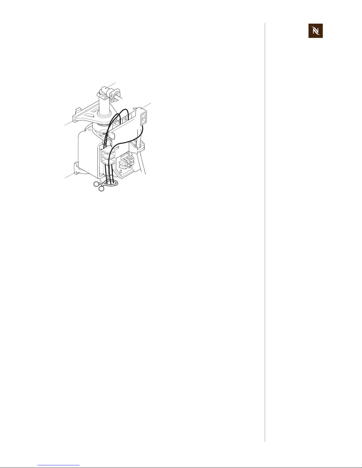
8.6.3 Replacing pump
General
The pump is available only completly equipped (20) with:
- pump prewired with thermal cut off
-
2 pump supports (21, 22)
- pump cover (25)
- connect elbow (23) with o-ring and clip
25
21
22
23
Page 78

Citiz service manual
78
REPAIRS
Replacing pump assembly
• Remove both hoses (28) from pump. Use a pair of pointed pliers to remove
connector clip (35) with O-ring (24).
• Remove cover (43) from electronic control board and disconnect 2 faston receptacles of pump wires.
• Pull out supports (21, 22) together with complete pump assembly.
21
22
32
43
35
28
24
Page 79

Citiz service manual
79
REPAIRS
Assembly checkpoints
• Check condition of supports (21, 22). Replace brittle supports.
• Pass hose (28) from pump to self priming device through lug on pump cover (25).
• Use a cable clamp (a) to fix pump wires.
28
25
a
Page 80

Citiz service manual
80
REPAIRS
8.6.4 Replacing flow meter
Assembly checkpoint
• Lay connection cable to flow meter (27) in bracket.
• Mind the hose positions on the flow meter.
27
27
Page 81

Citiz service manual
81
REPAIRS
8.6.5 Replacing automatic priming device (APD)
• Use a pair of pointed pliers to remove connector clips (35) from automatic priming
device (26).
35
26
36
35
Page 82

Citiz service manual
82
REPAIRS
Assembly checkpoints
• Replace both O-rings (36) together with automatic priming device (26).
• Insert hose (28) in tube guiding (30).
36
26
35
35
28
30
Page 83

Citiz service manual
83
REPAIRS
8.6.6 Replacing thermoblock with NTC sensor and fine
wire fuse(s)
A defect thermoblock can only be replaced with an assembly consisting of
- thermoblock, prewired with NTC temperature sensor, fine wire fuse(s) and ground
wire (only if required),
- thermoblock support.
• Release 3 latches and pull out support with thermoblock assembly (15).
Depending on
national regulations,
one or two fine wire
fuses are mounted on the
thermoblock (see “Wiring
diagrams” on page 97 and
following).
15
Do not stress NTC
cable when remov-
ing support.
Page 84

Citiz service manual
84
REPAIRS
Replacing NTC temperature sensor
• Unplug NTC sensor cable from electric control board (42) first.
• Test NTC temperature sensor (39), see “Replacing thermoblock with NTC sensor
and fine wire fuse(s)” on page 83.
Assembly checkpoint - NTC temperature sensor
• Tighten the new NTC temperature sensor (39) and spring ring with a torque wrench
(80 - 100 Ncm).
Replacing fine wire fuse(s) (not available separately)
Assembly checkpoints - fine wire fuse(s)
• When mounting a safety clip (a) on the thermoblock (15), make sure that the housing
of the fine wire fuse (b) is positioned exactly below the safety clip.
• Tighten fastening screw and spring ring with a torque wrench (150 (+30/-0) Ncm).
39
15
a
b
Page 85

Citiz service manual
85
REPAIRS
Assembly checkpoints - thermoblock
• All wires from thermoblock to platform must be led through the bracket (a) at the
bottom of the support.
• The black grommets (b) on the electrical thermoblock connections are slitted at the
end. If an angled Faston receptacle (c) is used, make sure that its wire runs through
this slit.
• Damping elements (62) correctly positioned and mount.
• Tighten central fastening screw (d) with a torque wrench (150 (+30/-0) Ncm).
a
d
b
c
Page 86

Citiz service manual
86
REPAIRS
8.6.7 Replacing electronic control board with button prints
• Remove at first
- NTC connector from electronic control board,
- connector cable from flow meter,
- electronic lid (43),
- faston receptacles from electronic control board.
• Insert tip of screwdriver between chassis (2) and protective case of electronic control
board (42) to release latches. Then pull out assembly.
Replacing button prints / coffee buttons
The replacement
board is equipped
with protective hous-
ing and cover.
2
42
43
9
11
Page 87

Citiz service manual
87
REPAIRS
Assembly checkpoints
• After assembly check the plug arrangement of the electronic control board (see
“Wiring diagrams” on page 97 and following.
• Lay connection wires to button prints in brackets and cable guide like shown.
For installing and
connecting a new
electronic control
board, the service technician must be earthed with
a grounding band.
Page 88

Citiz service manual
88
REPAIRS
8.7 Disassembly of core unit, D-range
8.7.1 General disassembly
The core unit has to be removed from the platform at first (see according chapter "platform disassembly"). It is possible to perform a general disassembly of the core unit with
intact hose and wire connections to the platform (for repair, leakage check etc.).
Remove outlet
1. Open closing handle.
2. Press outlet (5) sidewards by hand carefully.
3. Insert disassembly tool into gap between outlet and right side panel (4).
After general disassembly of the core
unit a repairing/service holder device is helpful
for further repair work.
5
4
The disassembly tool
is necessary for
removing outlet and
side panels undamaged.
Page 89

Citiz service manual
89
REPAIRS
4. Hold and pull outlet.
5. At the same time move disassembly tool upwards.
6. Carefully turn disassembly tool slightly backward to open the latch.
7. Insert disassembly tool into gap on the other side of the outlet.
8. Move disassembly tool upwards and carefully turn it slightly backward to open the
latch.
9. Remove outlet.
Remove right side panel
10. Insert disassembly tool between bottom of right side panel (4) and chassis.
11. Swivel disassembly tool till snap connection at the front opens.
12. Relocate disassembly tool and repeat procedure to open latch at the bottom of the
side panel.
10.
12.
4
Page 90

Citiz service manual
90
REPAIRS
13. Insert disassembly tool laterally into gap at the front.
14. Carefully turn disassembly tool slightly forward to open the first latch.
15. Move disassembly tool upwards and open the other two latches the same way.
16. At the back insert disassembly tool into shadow gap of right side panel.
17. Swivel disassembly tool carefully to open first latch.
18. Move disassembly tool upwards and repeat procedure for the other 2 latches.
Insert disassembly
tool at right angles
only. Otherwise the
shadow gap can be damaged.
Page 91

Citiz service manual
91
REPAIRS
19. Swing up and remove right side panel.
Remove left side panel
20. Insert disassembly tool between bottom of left side panel (3) and chassis.
21. Swivel disassembly tool till latch at the front opens.
22. Relocate disassembly tool and repeat procedure to open latch at the bottom of the
side panel.
Closing handle must
be opened.
20.
22.
3
Page 92
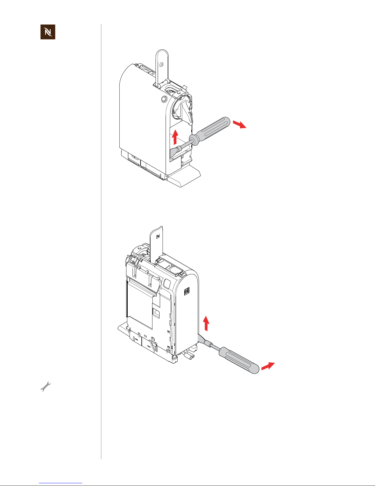
Citiz service manual
92
REPAIRS
23. Insert disassembly tool laterally into gap at the front.
24. Carefully turn disassembly tool slightly forward to open the first latch.
25. Move disassembly tool upwards and open the other two latches the same way.
26. At the back insert disassembly tool into shadow gap of left side panel.
27. Swivel disassembly tool carefully to open first latch.
28. Move disassembly tool upwards and repeat procedure for the other 2 latches.
Insert disassembly
tool at right angles
only. Otherwise the
shadow gap can be damaged.
Page 93

Citiz service manual
93
REPAIRS
29. Swing up and remove left side panel.
Remove cover (2)
1. Remove both coffee buttons (11, 12) and prints (42) out of holder.
2. Remove wiring of coffee button prints from cable guides.
Closing handle
should be opened.
42
12
11
1
Page 94

Citiz service manual
94
REPAIRS
3. Use a screwdriver to release 4 latches.
4. Open closing handle.
5. Lift and remove cover (1).
Assembly checkpoints
• Check if damper (10) for closing handle is installed on cover (1).
• For correct layout of the wires to the coffee button prints, see “Replacing electronic
control board with button prints” on page 95.
• Assemble left side panel (3) first.
• Insert right side panel (4) into hinges at the top of the left side panel. Then fold down
right side panel and click latches.
• Check that all latches are engaged.
1
10
3
1
4
Page 95

Citiz service manual
95
REPAIRS
8.7.2
Replacing electronic control board with button prints
• Refer to page 93 for removing cover (2).
• Remove first
- NTC connector from electronic control board,
- connector cable from flow meter,
- electronic lid (43),
- faston receptacles from electronic control board.
• Insert tip of screwdriver between chassis (1) and protective case of electronic control
board (42) to release latches. Then pull out assembly.
42
12
11
1
The replacement
board (42) is
equipped with protec-
tive housing and cover.
2
42
43
Page 96

Citiz service manual
96
REPAIRS
Assembly checkpoints
• The left and right button prints (42) are marked with "L" or "R" for easy identification.
• After assembly check the plug arrangement of the mainboard (see “Wiring
diagrams” on page 97 and following).
• Lay connection wires to button prints in brackets and cable guides like shown.
12
42
For installing and
connecting a new
electronic control
board, the service technician must be earthed with
a grounding band.
Page 97

Citiz service manual
97
REPAIRS
8.8 Wiring diagrams
8.8.1 Wiring diagrams - model Citiz
Wiring diagram 220 V - 240 V IEC - model Citiz, EF 451/452
Page 98

Citiz service manual
98
REPAIRS
Wiring diagram 220 V - 240 V IEC - model Citiz &milk, EF 467/468
Page 99

Citiz service manual
99
REPAIRS
Wiring diagram 120 V - 127 V IEC (Mexico) - model Citiz, EF 451/452
Page 100

Citiz service manual
100
REPAIRS
Wiring diagram 120 V - 127 V IEC - model Citiz & milk, EF 467/468
 Loading...