

Page 1

SERVICE MANUAL
PIXIE COFFEE MACHINES
PIXIE C EF 280
PIXIE D EF 281
Version 1.2 en
Page 2

Pixie service manual
2
CONTENTS
1 General Safety Notes ........................................................................................5
2 Main Components..............................................................................................6
2.1 Overview............................................................................................................ 6
2.2 Interior view........................................................................................................ 7
2.3 Fluid System ...................................................................................................... 8
2.3.1 Water circuit diagram................................................................................8
2.3.2 Water circuit..............................................................................................9
3 Technical Data ..................................................................................................10
3.1 Rating plates.................................................................................................... 10
3.1.1 Examples of brand specific rating plates ................................................10
3.1.2 Rating plate details (example) ................................................................11
3.2 Technical specifications................................................................................... 12
3.2.1 Dimensions and weight...........................................................................14
4 Operation............................................................................................................15
4.1 General information.......................................................................................... 15
4.2 Status indication............................................................................................... 15
4.3 Machine modes................................................................................................ 16
4.4 Program/reset fill up level................................................................................. 18
4.4.1 Programming the fill up level...................................................................18
4.4.2 Resetting the fill up level and auto shut off.............................................19
4.5 Empty water system......................................................................................... 19
4.6 Program auto shut off time............................................................................... 20
5 Maintenance ......................................................................................................21
5.1 Descaling ......................................................................................................... 21
5.1.1 Descaling procedure...............................................................................21
5.2 Cleaning procedure.......................................................................................... 25
6 Troubleshooting...............................................................................................26
6.1 Check list.......................................................................................................... 26
7 Repairs................................................................................................................28
7.1 Safety instructions............................................................................................ 28
7.2 Repair and mounting tips................................................................................. 28
7.3 Tools and accessories ..................................................................................... 30
7.4 General disassembly........................................................................................ 31
7.4.1 Prepare coffee machine for disassembly................................................31
7.4.2 Remove side panels ...............................................................................32
7.4.3 Remove power cord................................................................................33
7.4.4 Remove water guiding............................................................................35
7.4.5 Remove damper springs.........................................................................36
7.4.6 Remove closing handle...........................................................................37
7.4.7 Remove cable cover...............................................................................37
7.4.8 Remove right light guide.........................................................................38
7.4.9 Remove blind..........................................................................................39
Page 3

Pixie service manual
3
7.4.10Remove housing right.............................................................................39
7.4.11Remove main assembly .........................................................................44
7.4.12Remove front ring ...................................................................................46
7.4.13Remove key caps of push buttons.......................................................... 47
7.5 Replacing pump............................................................................................... 48
7.6 Replacing functional block............................................................................... 50
7.7 Replacing brewing unit..................................................................................... 52
7.8 Replacing flow meter ....................................................................................... 57
7.9 Wiring diagrams............................................................................................... 59
7.9.1 Wiring diagram 220 V - 240 V IEC..........................................................59
7.9.2 Wiring diagram 120 V UL (USA / Canada).............................................60
7.9.3 Wiring diagram 127 V IEC (Brazil).......................................................... 61
7.9.4 Wiring diagram 127 V IEC (Mexico) .......................................................62
7.9.5 Wiring diagram 100 V IEC (Japan).........................................................63
7.9.6 Wiring diagram 110 V IEC (Taiwan).......................................................64
8 Function tests................................................................................................... 65
8.1 Safety instructions............................................................................................ 65
8.2 Required equipment......................................................................................... 65
8.2.1 Overview................................................................................................. 65
8.2.2 Pressure gauge adapter.........................................................................66
8.2.3 Mounting pressure gauge adapter.......................................................... 67
8.3 Measure flow rate ............................................................................................ 68
8.4 Pressure and leakage checks.......................................................................... 69
8.4.1 Preparations ...........................................................................................70
8.4.2 Test run...................................................................................................71
8.5 Measure coffee temperature............................................................................ 72
8.6 Protective earth (PE) continuity test................................................................. 74
8.6.1 What is the protective earth continuity test about?.................................74
8.6.2 General...................................................................................................74
8.6.3 Test sequence........................................................................................75
8.6.4 What to do if the protective earth continuity test fails .............................76
8.7 Protective insulation test.................................................................................. 76
8.7.1 What is the protective insulation test about?..........................................76
8.7.2 General...................................................................................................76
8.7.3 Test sequence........................................................................................77
8.7.4 What to do if the insulation test fails.......................................................78
9 Explosion Drawings........................................................................................79
9.1 EF 280 Explosion drawing............................................................................... 79
9.2 EF 281 Explosion drawing............................................................................... 80
10 Parts List............................................................................................................ 81
10.1 Nespresso EF 280 / C60 and EF 281 / D60 .................................................... 81
10.2 208 Turmix TX160 CH..................................................................................... 83
10.3 281 DeLonghi EN125 EU................................................................................. 84
10.4 280 Krups XN300510 EU................................................................................. 85
10.5 281 Magimix M110 EU/GB .............................................................................. 86
10.6 281 Koenig D60 CH......................................................................................... 87
11 Notes................................................................................................................... 88
Page 4

Pixie service manual
4
PREFACE
The purpose of this service manual is to provide the service personnel with all necessary
information with regards to correct handling, maintenance and repair of the Pixie coffee
machines EF 280 and EF 281.
This manual should be used by the technicians as a valuable aid to guarantee the
permanent readiness for use of the machines. In order to take full advantage of all the
functions, it is absolutely necessary to follow the instructions in this manual.
Visit the Nespresso technical website periodically to check for upgrades, technical
modifications, counter measures etc. for these coffee machines:
https://business.nespresso.com
CONTENT UPDATES
Version 1.2
• Improved general disassembly procedures for cable cover and front ring.
Version 1.1
• Function test corrections in connection with translations of this service manual.
Version 1.0
• First released service manual version, in English only.
Please keep this
manual together with
the corresponding
service documentation.
This way you are assured
to have the necessary
information.
Access is restricted
and can be obtained
by asking your
Nespresso technical
contact person..
The version number
of this service manual
is printed on the lower
right corner of the front
page.
Page 5
Pixie service manual
5
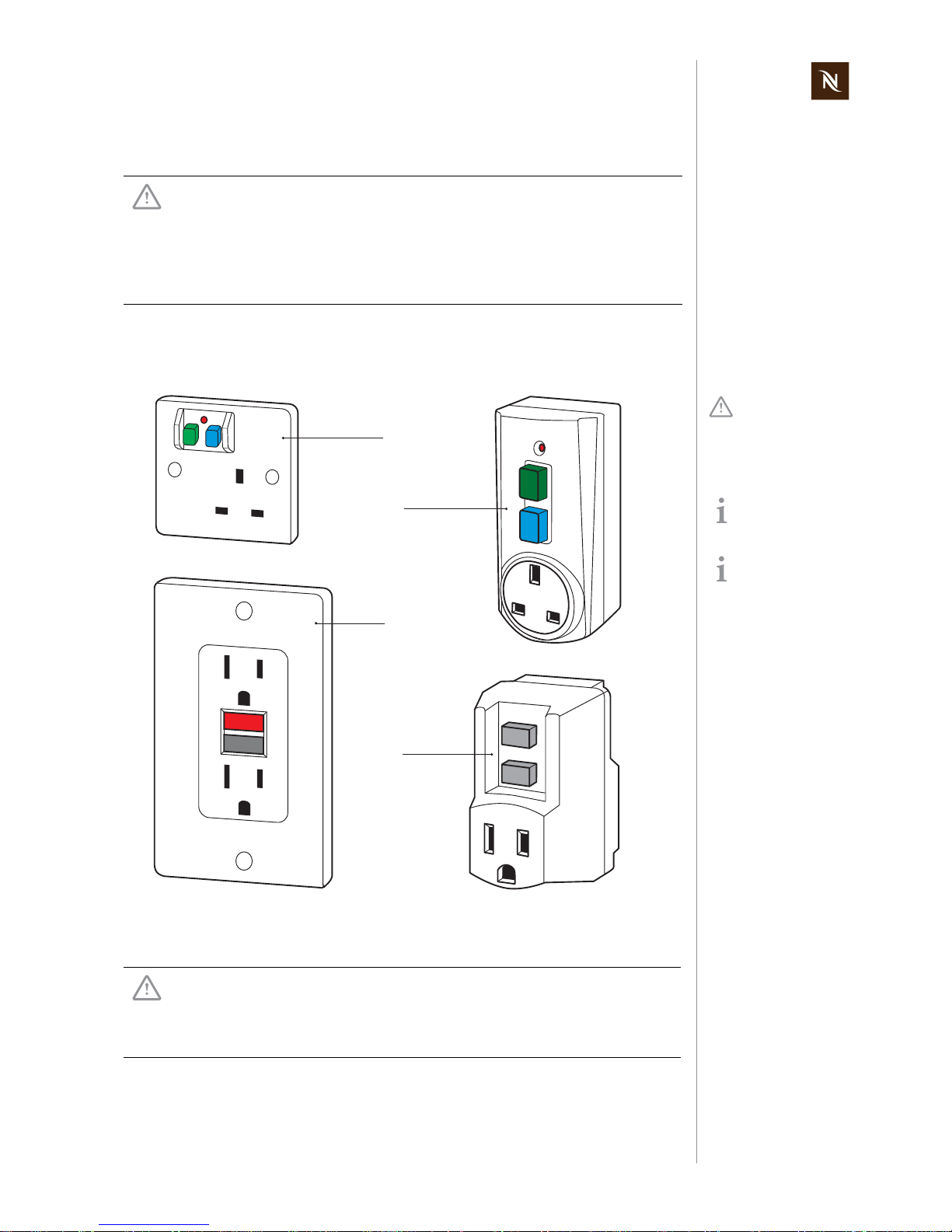
GENERAL SAFETY NOTES
1 GENERAL SAFETY NOTES
As an additional safety measure, the use of a residual current device (RCD), also called
a ground fault circuit interrupter (GFCI), in the repair centre is highly recommended.
Risk of fatal electrical shock and fire!
Mains voltage inside the coffee machine.
• Unplug appliance before cleaning.
• Never clean wet or immerse plug, cord or appliance in any fluid.
• Disconnect the mains plug before disassembly - the appliance must
be free of voltage.
This device does
not protect against
electrical shock due to
contact with both circuit
conductors.
Example illustrations
of typical devices.
Use a GFCI with a trip
level of 4 - 6 mA (USA)
resp. a RCD with a trip
level of 15 - 30 mA (Europe).
A trip level above 30 mA
provides only very limited
protection against harm
from an electric shock.
1) RCD protected socket-outlet
2) Plug-in RCD unit
3) GFCI socket
4) Plug-in GFCI
Danger of burns!
Hot parts and water under pressure inside the coffee machine
(particularly in the thermoblock).
• Let coffee machine cool down before cleaning or disassembly.
1
2
RESET
TEST
RESET
TEST
3
4
Page 6
Pixie service manual
6
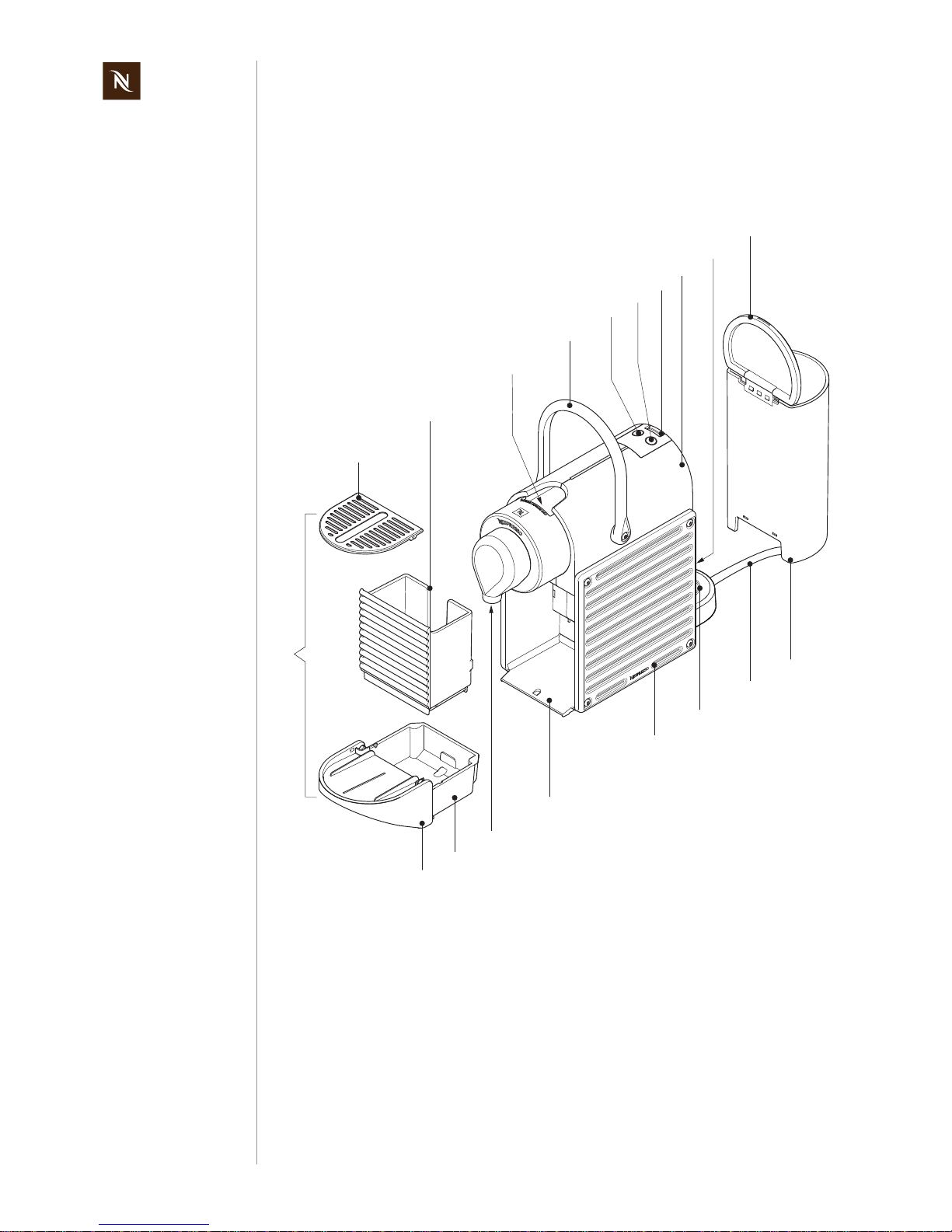
MAIN COMPONENTS
2 MAIN COMPONENTS
2.1 Overview
1) Drip grid
2) Capsule container for used capsules
(backlighted)
3) Feed opening for capsule
4) Closing handle
5) Coffee button "small cup" / "Espresso"
(backlighted)
6) Coffee button "large cup" / "Lungo"
(backlighted)
7) On/Off switch
8) Housing right
9) Water level detection
10) Water tank lid
11) Water tank
12) Power cord
13) Water tank connector
14) Side panel left/right
15) Housing left
16) Coffee outlet
17) Waste water container
18) Folding cup support
19) Maintenance unit
15
1
2
17
4
3
16
5
7
10
11
12
6
18
14
13
8
9
19
Page 7
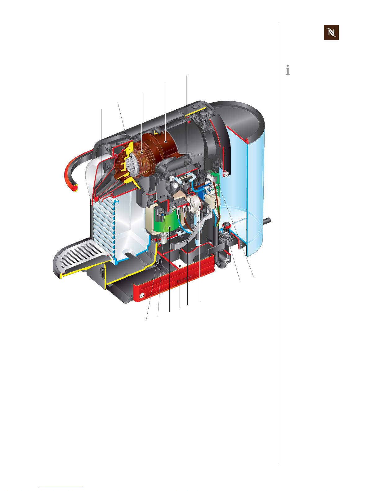
Pixie service manual
7
MAIN COMPONENTS
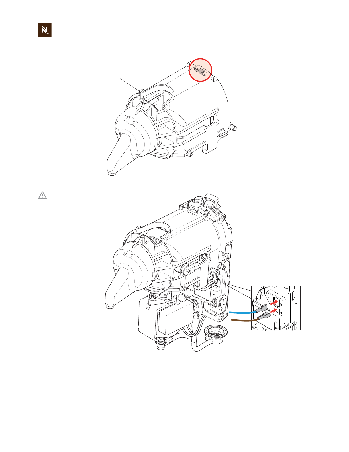
2.2 Interior view
This interior view
shows the wired coffee machine model
Pixie C.
1) Steam cover
2) Pyramid plate
3) Brewing device
4) Thermoblock
5) Sound damper
6) Electronic control board
7) Water tank valve
8) Flow meter
9) Light guide (for capsule container)
10) Opening in the housing to store excess
lenght of power cord
11) Pump
12) Thermal cut off fuse
13) Magnetic mounting
2
3
4
7
8
9
11
12
6
10
13
1
5
Page 8
Pixie service manual
8
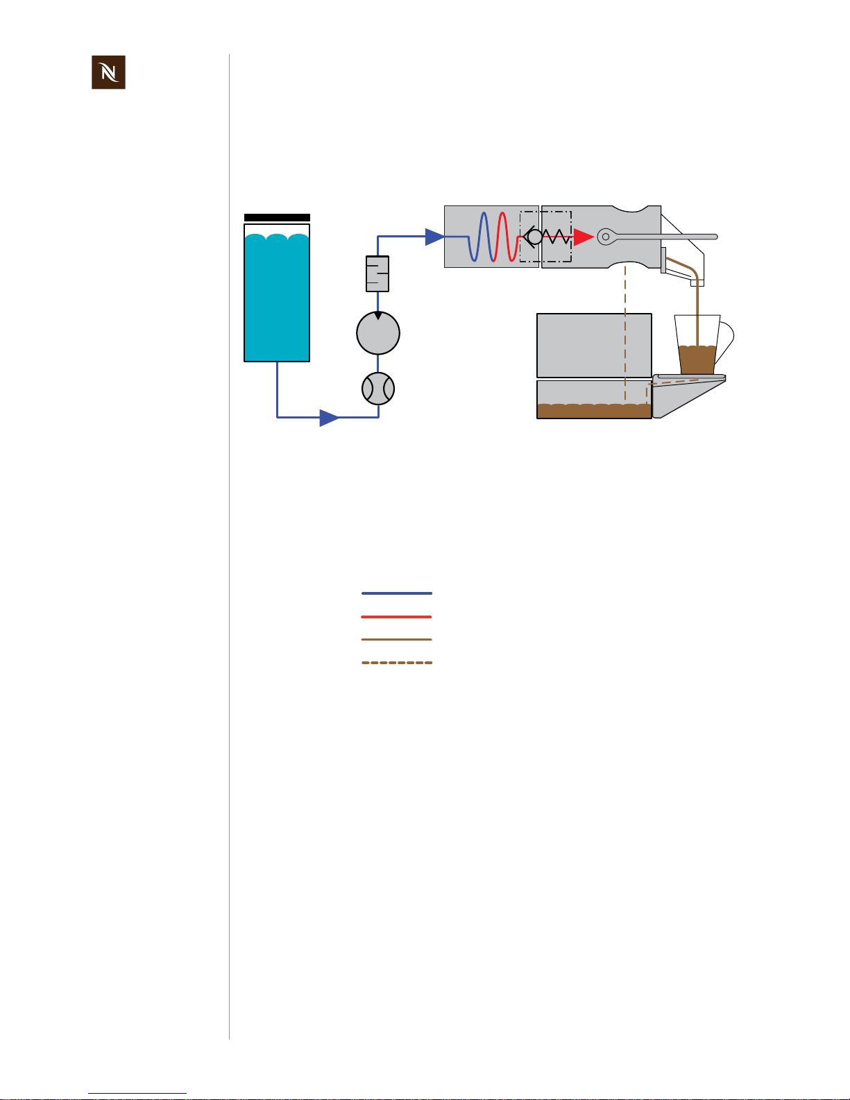
MAIN COMPONENTS
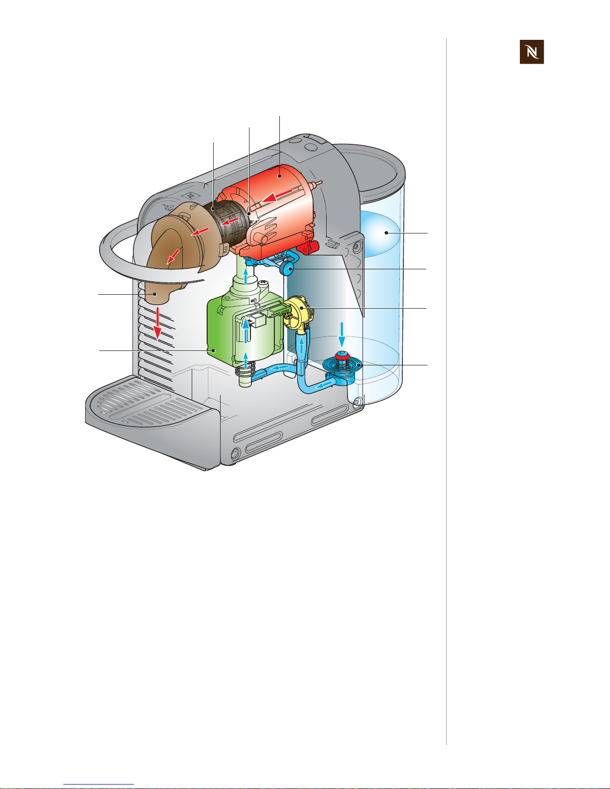
2.3 Fluid System
2.3.1 Water circuit diagram
Legend:
1) Water tank
2) Flow meter
3) Pump
4) Sound damper
5) Thermoblock
6) Check valve
7) Brewing unit
8) Capsule container
9) Waste water container
10) Drip grid
Fresh cold water
Fresh hot water
Coffee
Waste/drip water
BU
TB
1
3
2
5
7
8
9
10
4
6
Page 9
Pixie service manual
9
MAIN COMPONENTS
2.3.2 Water circuit
1) Pump
2) Coffee outlet
3) Brewing unit
4) Check valve
5) Thermoblock
6) Water tank
7) Sound damper
8) Flow meter
9) Water tank connector
3
5
4
2
1
6
7
8
9
Page 10
Pixie service manual
10
TECHNICAL DATA
3 TECHNICAL DATA
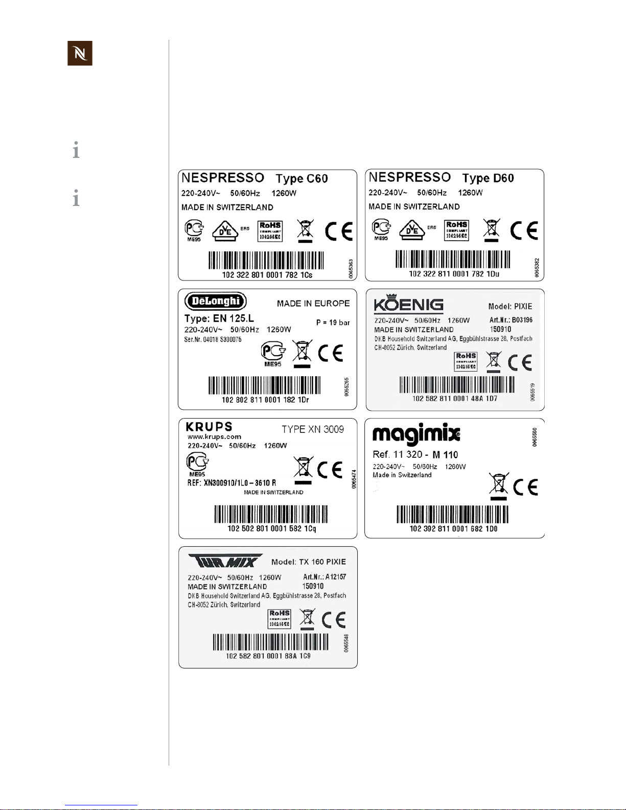
3.1 Rating plates
3.1.1 Examples of brand specific rating plates
The rating plate can
be found at the bottom of the coffee
machine.
This overview shows
examples of various
brands and is subject
to alterations.
Page 11
Pixie service manual
11
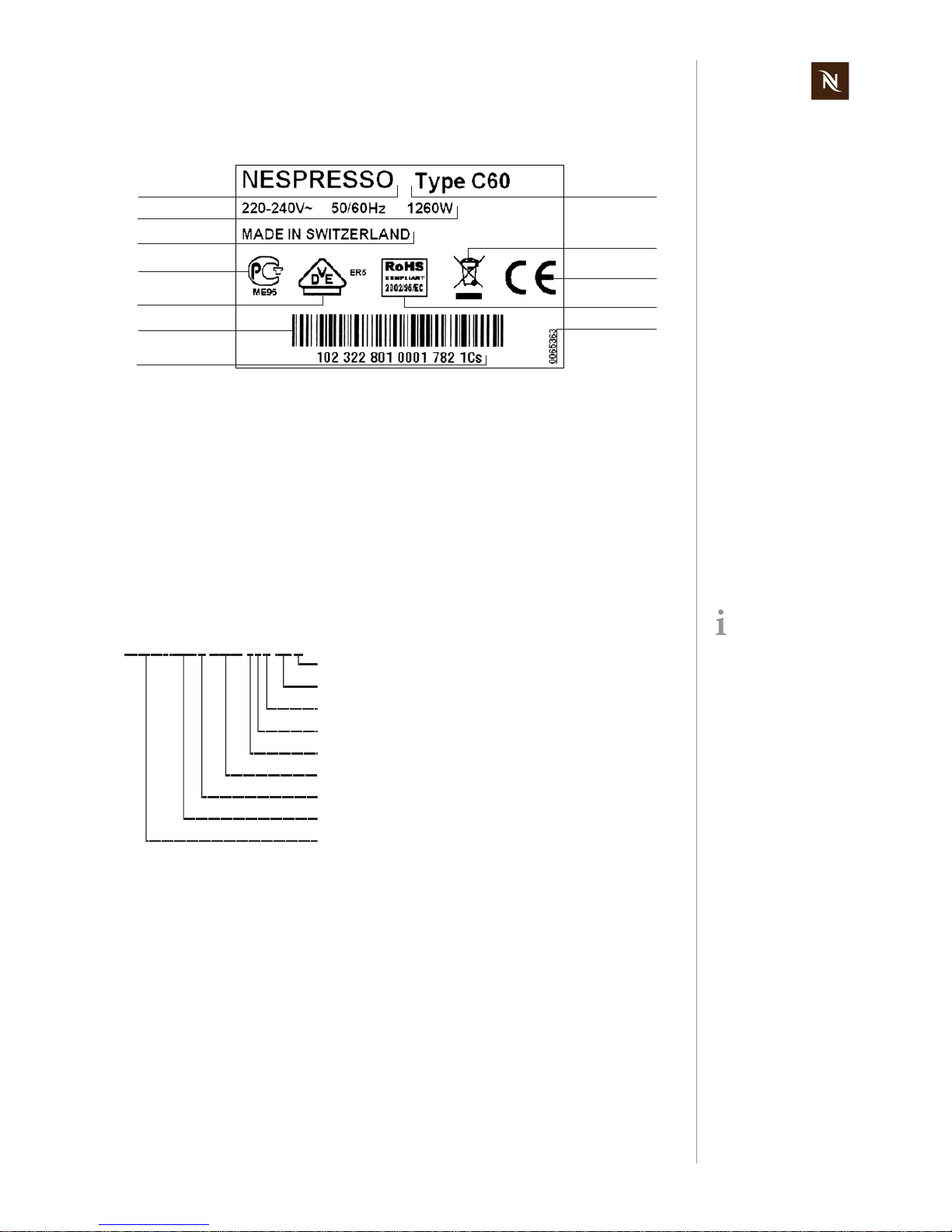
TECHNICAL DATA
3.1.2 Rating plate details (example)
Decoding the alphanumeric serial number
Example:
1) Brand name
2) Voltage and power rating
3) Place of manufacture
4) National approval sign of Russia
(GOST R)
5) National approval sign of Germany
(VDE)
6) Barcode
7) Serial number
8) Machine type
9) Special disposal icon
(do not dispose with ordinary waste)
10) Sign of conformity (CE)
11) Conformity with RoHS guidelines (lead
free solder, etc.)
12) Article number of the rating plate
1
2
3
6
7
8
9
10
12
4
5
11
By decoding the date
of production and
machine type, the
coffee machine can be
identified exactly.
Checksum
Color version
Type of mains plug
Mains voltage
Distributing partner
Incremental number per production day
Manufacturing plant
Manufacturer designation of the machine type (EF 280)
10232 ... Date of production
(10 = year 2010, 232 = 232nd day of the year)
102 322 801 0001 782 1Cs
Page 12

Pixie service manual
12
TECHNICAL DATA
3.2 Technical specifications
Mains voltage ranges
- Europe, RU, AU, CN, KR, SG, HK, ME, ZA, IL, BR, AR............ 220-240 V, 50/60 Hz
- USA, Canada..................................................................................... 120 V, 50/60 Hz
- BR, MX............................................................................................... 127 V, 50/60 Hz
- Japan ................................................................................................ 100 V, 50/60 Hz
- Taiwan.................................................................................................... 110 V, 60 Hz
Power consumption
220-240 V mains voltage......................................................................approx. 1’260 W
100/110/120/127 V mains voltage.........................................................1’160 - 1’370 W
Power consumption of coffee machine main components
(for all voltages and frequencies)
Thermoblock......................................................................................................1’200 W
Pump......................................................................................................................60 W
Energy consumption (CECED / FEA 2009 method)
Energy efficiency class level ............................................................................. A - 40%
Daily energy consumption....................................................................................72 Wh
Annual energy consumption..........................................................................26.28 kWh
Pump
Pump pressure
- Max. permissible....................................................................................20 bar ± 3 bar
- During coffee preparation (depending on the type of coffee)........................9 - 16 bar
Capacities
Water tank.................................................................................................. approx. 0.7 l
Waste water container......................................................................................... 190 ml
Capsule container .......................................................................... approx. 10 capsules
EuP ... Energy using
Products
See commission regulation no. 1275/2008 of the
European Union.
Approvals CE, UL "for USA and Canada", PSE, Gost R, Ctick,
CCC, KTL, SPRING, SASO, SABS, ISI, IRAM, NOM
EuP standard The coffee machine is EuP 2013 compliant
Advised water tank
capacity to avoid
spilling.
Page 13

Pixie service manual
13
TECHNICAL DATA
Volume of prepared coffee
- factory settings
Small cup "Espresso".................................................................................. 40 ml (±7%)
Large cup "Lungo"..................................................................................... 110 ml (±7%)
- customer settings
Programmable setting range.........................................................................20 - 200 ml
Environmental conditions
Operating temperature............................ + 5 °C up to + 45 °C (+ 41 °F up to + 113 °F)
Storage temperature..................................- 25 °C up to + 65 °C (- 13 °F up to 149 °F)
Altitude............................................................................up to 2’500 m above sea level
Humidity...................................................................................................no restrictions
Various data
Preheating time.......................................................................................approx. 25 sec
Automatic shut off time.................................................................after 9 min of non-use
Safety temperature (electronically controlled)....................................... 120 °C (248 °F)
Safety temperature (thermal cut-off)..................................................... 167 °C (333 °F)
Coffee temperature at outlet ...........................................86 °C ± 3 °C (187 °F ± 5,4 °F)
Page 14
Pixie service manual
14
TECHNICAL DATA
3.2.1 Dimensions and weight
Dimensions ( length x width x height)............................................ 326 x 111 x 235 mm
Power cable length...............................min. 0.8 m (depending on national regulations)
Cup support, folded down ....................... 90 mm, for espresso and lungo cups/glasses
Cup support, tilted up....................................................146 mm, for macchiato glasses
Weight (without water)............................................................................. approx. 2.8 kg
Dimensions in [mm].
235
326
111
90
146
Page 15
Pixie service manual
15
OPERATION
4 OPERATION
4.1 General information
For an overview of operational controls see “Main Components” on page 6.
For basic operation of the machine such as preparing a coffee and other related infor-
mation, refer to the user manual.
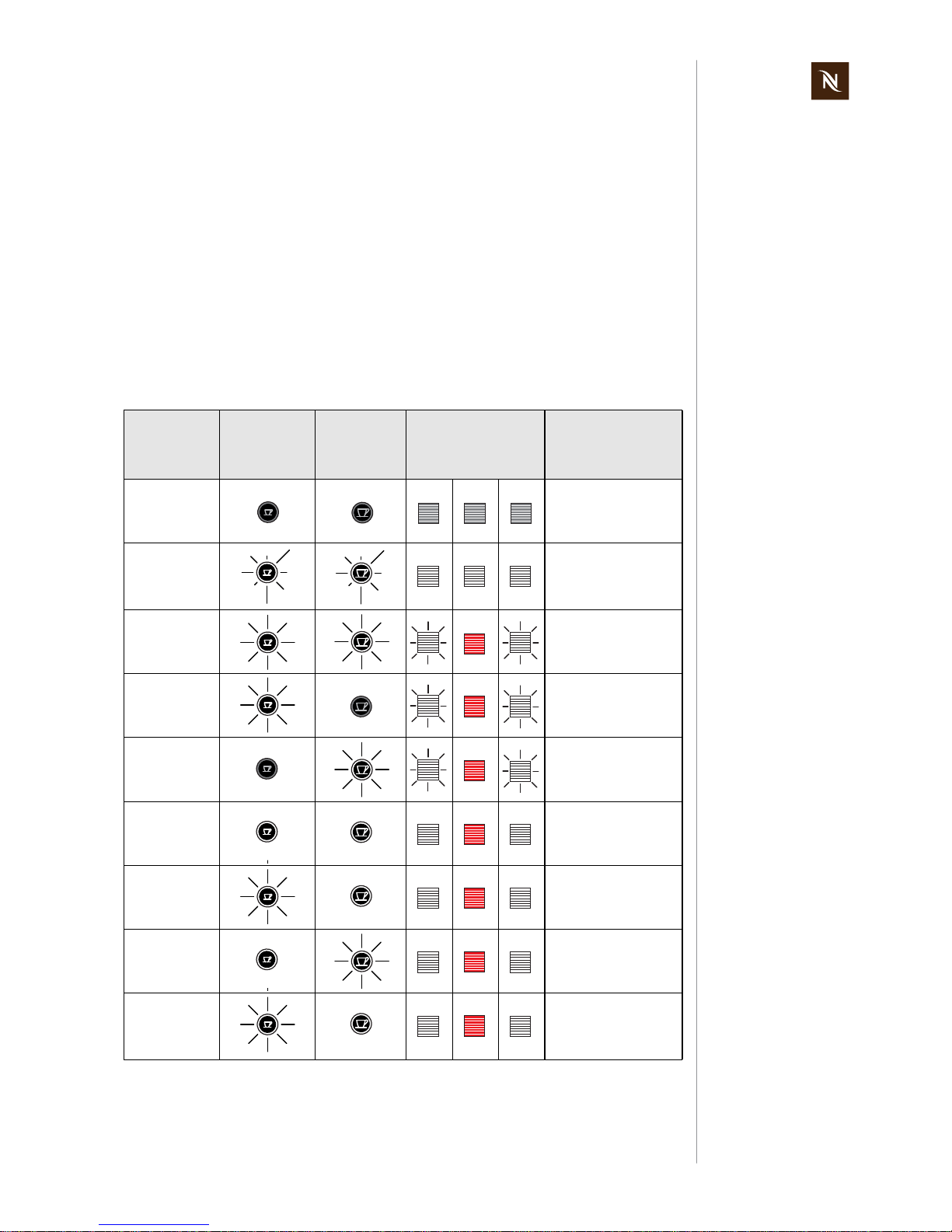
4.2 Status indication
According to the following table the status of the coffee machine is shown by
- the two coffee buttons with white backlight
- the capsule container with white or red backlight.
Machine
status etc.
"Small cup"
button
"Large cup"
button
Capsule container
backlight
Water tank level
high / low / missing
LED signal
Off All LED‘s off
Error
Blinking fast (2 Hz,
0.25 s on/0.25 s off)
3 times every 2 seconds, alternating
Heat up
Blinking 1 Hz,
0.5 s on, 0.5 s off
Preselect
small cup
Blinking 1 Hz,
0.5 s on, 0.5 s off
Preselect big
cup
Blinking 1 Hz,
0.5 s on, 0.5 s off
Ready LED‘s on
Brewing small
cup
Blinking 1 Hz,
0.5 s on, 0.5 s off
Brewing big
cup
Blinking 1 Hz,
0.5 s on, 0.5 s off
Rinse small
cup
Blinking 1 Hz,
0.5 s on, 0.5 s off
(same as brewing
small cup)
Page 16
Pixie service manual
16
OPERATION
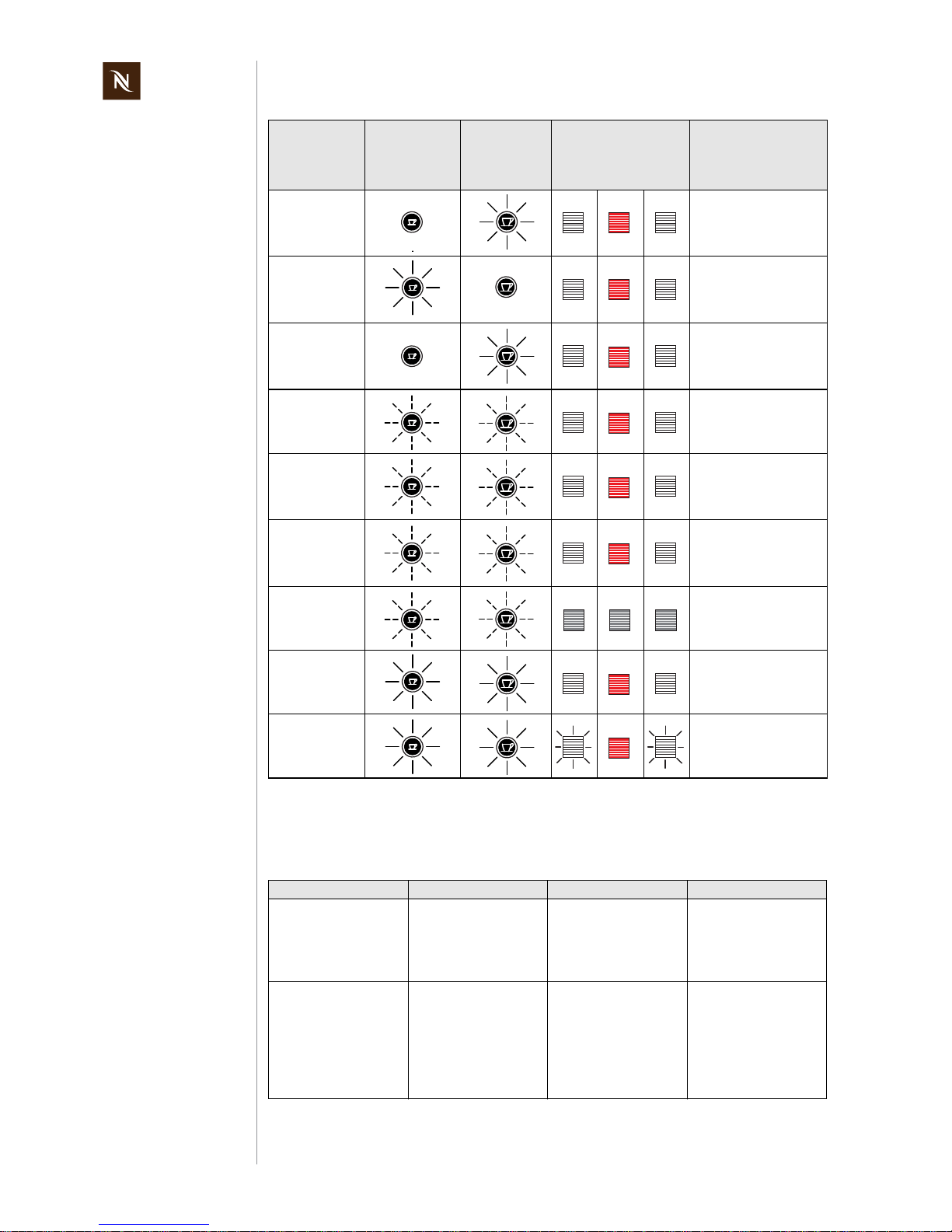
4.3 Machine modes
This table helps to understand the operating modes of the Pixie coffee machines:
Rinse big cup
Blinking 1 Hz,
0.5 s on, 0.5 s off
(same as brewing big
cup)
Volume brewing small cup
Blinking 1 Hz,
0.5 s on, 0.5 s off
(same as brewing
small cup)
Volume brewing big cup
Blinking 1 Hz,
0.5 s on, 0.5 s off
(same as brewing big
cup)
Descaling
ready
Blinking 2 Hz,
0.25 s on, 0.25 s off
Descaling
process pump on
Blinking 2 Hz,
0.25 s on, 0.25 s off
(same as descaling
ready mode)
Descaling
process pump off
Blinking 2 Hz,
0.25 s on, 0.25 s off
(same as descaling
ready mode)
Emptying /
evaporating
Blinking 2 Hz,
0.25 s on, 0.25 s off
Resetting
Blinking 1 Hz,
0.5 s on, 0.5 s off
(same as heat up)
Overheat
Blinking 1 Hz,
0.5 s on, 0.5 s off
(same as heat up)
Machine mode Enter mode Actions Exit mode
1 Heat up mode
Every time after switching on machine
Heats up thermoblock
to ready temperature
90 °C within 30 sec
without overshooting
target temperature
e.g. switching off
machine
2 Self test mode
Every time after switching on machine
Tests:
• NTC short circuit
• NTC connected
• Checks if thermoblock reaches ready
temperature within
2 min after switch on
e.g. switching off
machine
Machine
status etc.
"Small cup"
button
"Large cup"
button
Capsule container
backlight
Water tank level
high / low / missing
LED signal
Page 17

Pixie service manual
17
OPERATION
3 Ready mode
• After heat up and self
test mode was ok
• After brewing or
volume brewing
coffee
• After reset mode
• After leaving
descaling mode
Keeps thermoblock
temperature at 90 °C
e.g. switching off
machine
4a Brewing mode
4b Volume brewing
mode (programming cup size)
• Press and release
coffee button "large
cup" or "small cup"
(brewing mode)
• Press and hold
coffee button "large
cup" or "small cup"
for more than 3 s
(programming mode)
• Press and release
coffee button "large
cup" or "small cup"
when machine was
in brewing mode or
automatic exit given
by the flow meter
• Release coffee
button "large cup" or
"small cup" when
machine is in
programming mode
• Switch off machine
5 Descaling mode
• Switch on machine,
wait until ready
• Press and hold both
coffee buttons for at
least 3 sec
• Regulates temperature to 55 °C (after
pump was started)
• Stops and starts
pump with any coffee
button, no volume
brewing in descaling
mode
• Press and hold both
coffee buttons for
1 sec
Note: When machine is
switched off during any
descaling mode, then it
goes to descaling
mode ready state after
next switch on.
6 Emptying mode
(evaporing)
1) Switch off machine
2) Press and hold
coffee button
"small cup"
3) Switch on machine
1) Starts pump
2) Stops pump after
10 sec
3) Heats up thermoblock to 105 °C
(100% power)
4) Switches off thermoblock
5) Switches off
machine
6) Blocks machine for
10 min
Switch off machine
7 Resetting mode
1) Switch off machine
2) Press and hold
coffee button
"large cup"
3) Switch on machine
• Resets programmed
large and small
coffee volumes to
factory setting
• Indicates the resetting mode for 3 sec
Proceeds with self test
mode automatically
8 Auto switch off mode
(factory setting of 9 min
can be changed to
30 min - see page 20)
Automatically after a
certain period of nonuse
• Switch off machine
after 9 min resp.
30 min if no coffee is
brewed or 9 min
resp. 30 min after
last brewed coffee
9 Failure mode
Automatically by following failures:
a) NTC short circuit
b) NTC not connected
c) Heat up too slow
Machine indicates failure with blinking coffee
buttons as long as the
failure is present
When failure is fixed
Machine mode Enter mode Actions Exit mode
Page 18
Pixie service manual
18
OPERATION
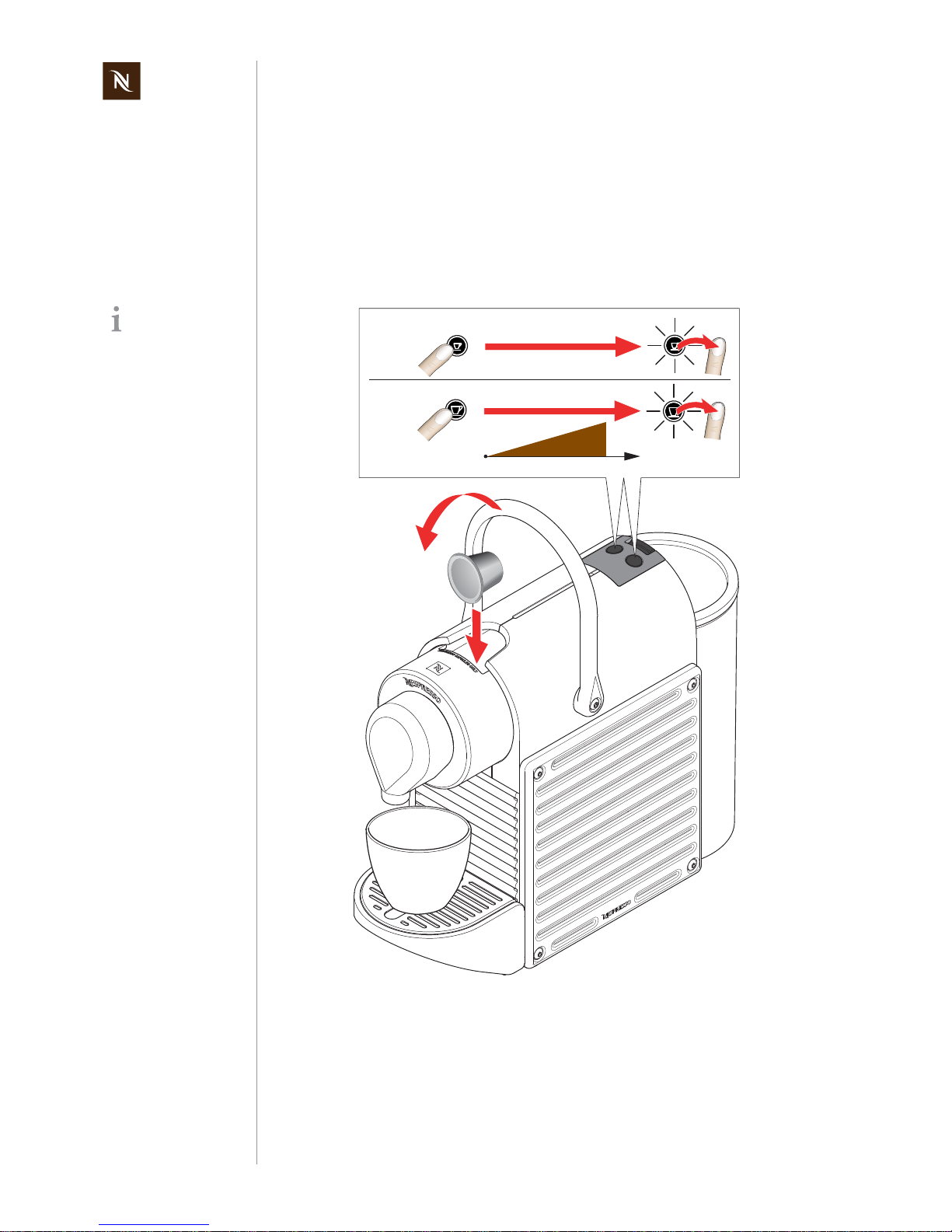
4.4 Program/reset fill up level
Each coffee button can be programmed with a coffee volume for an individual cup size.
The procedure for programming/resetting is the same for both coffee buttons.
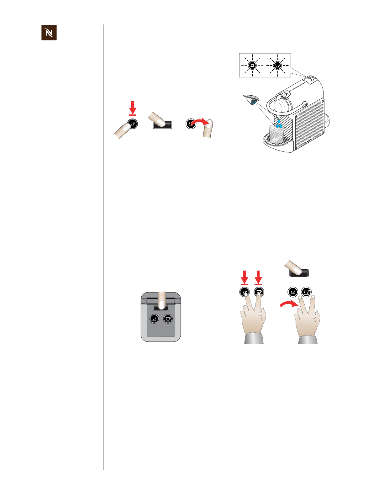
4.4.1 Programming the fill up level
Programmable volume range........................................................................20 - 200 ml
Each new programming cycle starts with
the min. volume
(20 ml after 3 sec), regardless of a preprogrammed
coffee volume.
1) Prepare coffee as usual (see user
manual), but keep the coffee button
pressed for at least 3 seconds in
order to start programming mode.
2) Only release the button when the
desired fill level is reached.
min
3 sec
max 200 ml
20 ml
200 ml
max 200 ml
min
3 sec
Page 19
Pixie service manual
19
OPERATION
4.4.2 Resetting the fill up level and auto shut off
With the following procedure all programmed fill up levels will be set back to this factory
settings:
Coffee button "small cup" / "Espresso".................................................................. 40 ml
Coffee button "large cup" / "Lungo"...................................................................... 110 ml
Additionally the auto shut off time will be set back to 9 min (factory setting).
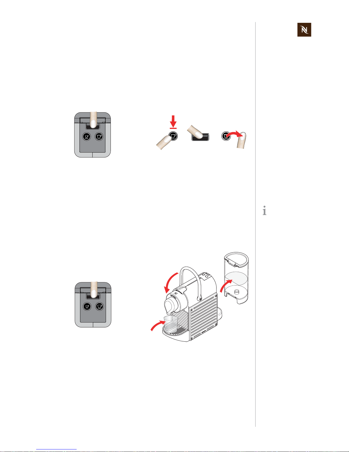
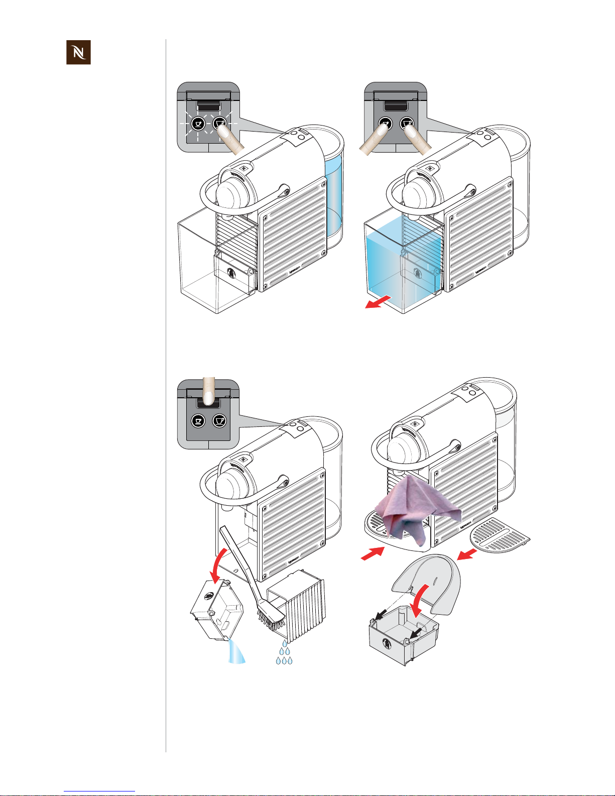
4.5 Empty water system
After every operation, some water (max. 25 ml) remains in the coffee machine. Therefore the water system must be emptied
- if the coffee machine will not be used for a long time
- as antifreeze measure
- for repairs and shipment.
1) Switch off the coffee machine. 2) Press and hold the button "large cup".
3) Switch on the coffee machine.
4) Release button "large cup".
1
OFF
2
3
4
ON
After this procedure,
the coffee machine
will not be ready for
approx. 10 min (until the
thermoblock cools to below
100 °C ).
1) Switch off coffee machine. 2) Remove water tank.
3) Place a receptacle under the coffee
outlet.
1
OFF
2
3
Page 20
Pixie service manual
20
OPERATION
4.6 Program auto shut off time
The auto shut off time of 9 min can be changed to 30 min with the following procedure:
To set the auto shut off time back to the factory default of 9 min, see page 19.
4) Press and hold button "small cup".
5) Switch coffee machine on again.
6) Release button "small cup".
- The coffee buttons blink fast simultaneously.
- The pump starts to drain the water
system and stops automatically.
- After heating up the therrmoblock, the
machine switches itself off automatically and blocks the On/Off switch for
approx. 10 min.
1) Switch off coffee machine. 2) Press and hold both coffee buttons.
3) Switch coffee machine on again.
4) Release both coffee buttons.
4
5
6
ON
Automatic
switch off
1
OFF
2
3
4
ON
Page 21
Pixie service manual
21
MAINTENANCE
5 MAINTENANCE
5.1 Descaling
5.1.1 Descaling procedure
Only use Nespresso descaler (5034) or Nespresso descaling kit
(3035/CBU-2) – never use vinegar!
Descaler can damage casing and surfaces.
Immediately clean drops of descaling solution.
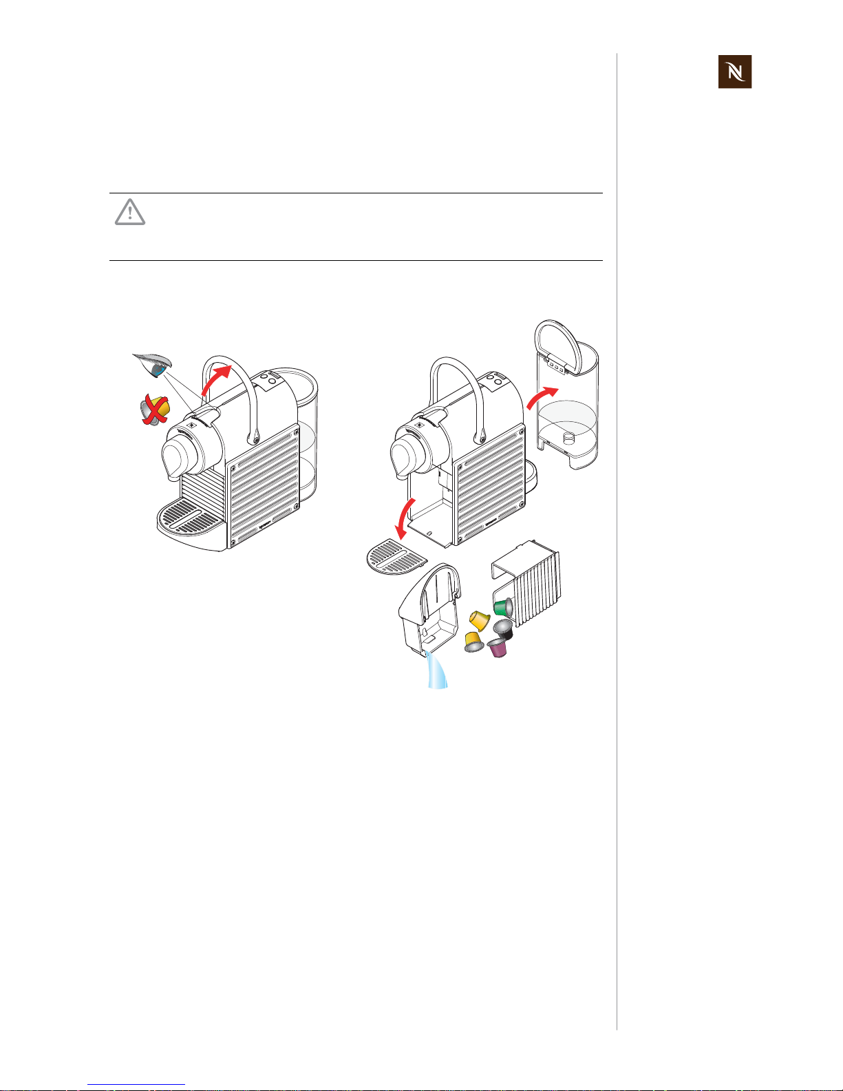
1) Eject capsule or check if capsule is
removed.
2) Remove and empty water tank, capsule and waste water container.
1
2
Page 22
Pixie service manual
22
MAINTENANCE
Fold cup support up
to the stop before
pulling it out of the
hinges.
Use a container with a
capacity of min. 1 l.
3) Fold up and release cup support from
waste water container.
4) Re-insert capsule and waste water
container.
5) Place a container under coffee outlet.
3
5
4
Observe the safety
instructions on the
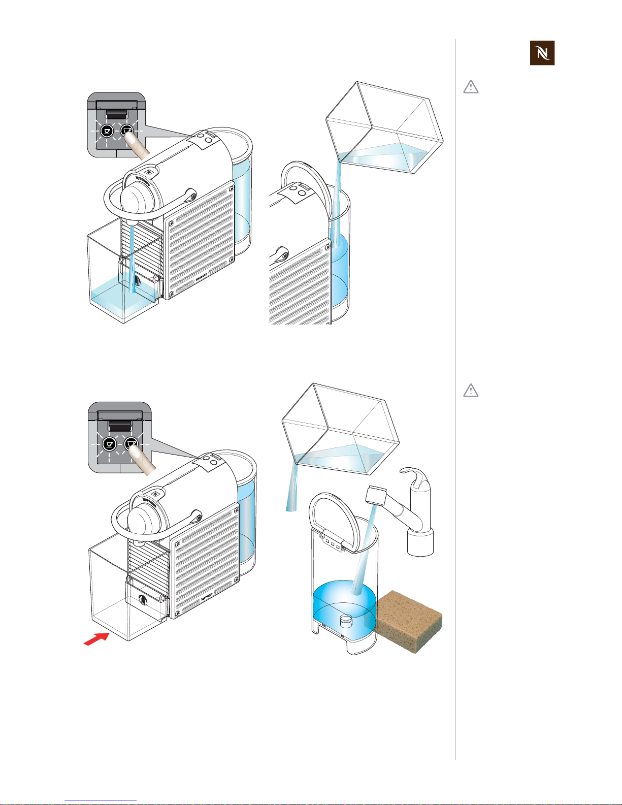
descaler package.
6) Fill measuring jug with 0.1 l (1 bag) of
Nespresso descaling liquid and 0.5 l
fresh, potable water.
7) Fill descaling solution in water tank.
8) Insert water tank into the coffee
machine.
9) Switch machine on and wait till
machine is ready.
10) Press both coffee buttons simultaneously for at least 3 sec.
- The machine is in descaling mode now
(both coffee buttons blinking fast).
6
8
0.5 l
0.1 l
7
9
10
3 sec
Page 23
Pixie service manual
23
MAINTENANCE
Danger!
Hot splashes of
descaling solution.
Do not open closing handle during descaling
process.
11)
Press any coffee button to start pump.
Let the entire solution in the tank run
through the system.
12) After water tank is empty, pour descaling solution back into water tank.
11
12
Danger of injury!
Residual descaler
may be harmful.
Rinse thoroughly to
remove any residue.
13) Place empty container back under coffee outlet.
14) Descale again: press any coffee
button
and wait until water tank is empty.
15) Empty container and put it back under
coffee outlet.
16) Rinse and clean water tank thoroughly
and fill it with fresh potable water.
13
14
16
15
Page 24
Pixie service manual
24
MAINTENANCE
17) Rinse coffee machine by pressing any
coffee button and wait until water tank
is empty.
18) Press both coffee buttons simultaneously for at least 1 sec to end descaling mode.
19) Remove and empty container.
20) Switch off coffee machine.
21) Empty and clean capsule and waste
water container.
22) Clip cup support on waste water container.
23) Clean coffee machine with a damp
cloth if necessary.
17
18
1 sec
19
21
20
22
23
Page 25
Pixie service manual
25
MAINTENANCE
5.2 Cleaning procedure
Risk of fatal electrical shock and fire!
Never clean wet or immerse plug, cord or appliance in any fluid.
Unplug appliance and let it cool down to avoid burns.
Never use brushes
and/or cleaning
agents that contain
aggressive or chemical
components resp. solvents.
Do not put any part in a
dishwasher.
Use only a damp cloth or
sponge and a mild cleaning
agent if necessary
1) Switch machine off.
2) Check if capsule is ejected.
3) Empty and clean
- capsule container (a)
- waste water container (b) with
- cup support (c) and drip grid (d).
2
1
OFF
3
a
b
c
d
Do not use a brush -
the water tank can be
scratched.
4) Empty, rinse and clean water tank.
5) Reassemble coffee machine.
6) Clean coffee outlet with a damp cloth.
7) Clean coffee machine with a damp
cloth if necessary.
5
4
6
7
Page 26
Pixie service manual
26
TROUBLESHOOTING
6 TROUBLESHOOTING
6.1 Check list
After an initial inspection in accordance
with this check list,
errors are quickly found and
corrected with the appropriate measure.
Therefore, adhere to the
sequence of the check list.
Repair every occurring error
and work the check list
through until it is completed.
Check Error symptoms
Measure /
repair work
Further measures /
repair work
1 Check the coffee
machine for visible damage
1.1 Housing parts broken or damaged
YES - replace housing parts if
necessary
NO - continue
1.2 Power cord damaged
YES - replace power cord
NO - connect power cord of
machine to the mains and continue
2 Check mechani-
cal components
2.1 Cup support with
capsule and waste
water container
does not remain in
fitting position
YES - check if waste water
container has its metallic plate
for magnetic mounting
NO - continue
NO - replace waste water container.
2.2 Cup support rattles
when folded down
or during operation
YES - check if 2 rubber stoppers are mounted on waste
water container
NO - continue
NO - replace stoppers
2.3 Closing handle
malfunction
YES - it is very difficult or
almost impossible to close the
handle and to press it all the
way down
NO - continue
YES - replace brewing unit
2.4 Capsule is not
ejected correctly
YES - replace brewing unit
NO - continue
3 Fill water tank 3.1 Water tank leaks
YES - replace water tank
NO - continue
4 Activate On/Off
switch to perform
automatic self test
4.1 Coffee machine is
not working
(does not function)
a) YES - power cord is okay
(loose connection)
YES - continue
NO - replace power cord
b) YES - On/Off switch has typical switching noise
YES - continue
NO - replace functional block
c) YES - pump works (press a
coffee button)
YES - continue with point e)
NO - continue with point d)
d) YES - both coffee buttons
are working
YES - replace pump
NO - replace functional block
e) YES - fine wire fuses or triac
on thermoblock defective
YES - replace thermoblock
NO - continue
f) YES - wiring is okay
NO - continue with point 4.2
YES - replace functional block
NO - replace defective cables
4.2 Both coffee buttons
are blinking 3x fast
YES - thermoblock is hot
NO - self test ok - continue
YES - switch off/on coffee
machine and check again
NO - replace thermoblock or
functional block
Page 27
Pixie service manual
27
TROUBLESHOOTING
5 Rinse coffee
machine
5.1 No water at coffee
outlet
YES - a) water system is empty
YES - open the closing handle
and press a coffee button several times to fill the water system
NO - continue
YES - b) coffee machine is calcified
NO - continue
YES - descale coffee machine
(see page 21)
YES - c) pyramide plate
blocked
YES - replace brewing unit
NO - continue
YES - d) flow meter blocked YES - clean or replace flow
meter
NO - continue
YES - e) pump cannot produce
sufficient water pressure
YES - replace pump
NO - continue
6 Measure coffee
temperature during coffee preparation (see page
72)
6.1 Temperature is too
low (below 83°C)
YES - descale coffee machine
(see page 21)
NO - continue
6.2 Temperature too
high (over 89 °C)
YES - replace thermoblock
NO - continue
7 Check for leakage
(see page 69) and
measure flow rate
(see page 68)
7.1 Hose connections
leak
YES - replace sound damper
NO - continue
7.2 Brewing unit leaks YES - replace brewing unit
NO - continue
7.3 Rate of flow not
within standard
range (60-120ml in
30 sec)
YES - coffee machine is calcified
NO - continue with point 9
YES - descale coffee machine
(see page 21)
NO - replace pump
8
Descale coffee
machine
(if necessary)
8.1 Coffee machine is
calcified
YES - descale coffee machine
(see page 21)
NO - continue with point 9
9 Check water tank
contents after descaling and rinising
9.1 Particles of calcium
and rust visible in
water
YES - descale and rinse coffee
machine again to clean water
circuit
(see page 21)
NO - continue
YES - inform customer to descale coffee machine periodically and to use the specified
descaling product only.
10 Final cleaning
(see page 25)
No errors found according to
check list?
YES - for more information
please contact Nespresso
Service Division
End of check list
Check Error symptoms
Measure /
repair work
Further measures /
repair work
Page 28

Pixie service manual
28
REPAIRS
7 REPAIRS
These repair instructions
- are based on exploded drawings with position numbers combined with repair and
mounting tips,
- presuppose basic knowledge in repairing Nespresso coffee machines.
7.1 Safety instructions
7.2 Repair and mounting tips
These general advices are completed with specific repair tips in this chapter.
Additional information
For components not mentioned in this repair chapter, refer to the chapters "Explosion
Drawings" on page 79 and "Parts List" on page 81.
Snap connections
Parts of the case and components of the coffee machine are connected screwless with
latches.
When loosening these latches, proceed with care and patience to avoid
causing any damage.
Screw connections
Do not overtighten screws of side panels. Plastic threads and inserts are delicate.
Observe max. torque for the screw connections according to the following table:
Risk of fatal electrical shock!
Mains voltage inside the coffee machine.
Disconnect the mains plug before disassembly - the coffee machine
must be free of voltage.
Danger of burns!
Hot parts and water under pressure inside the coffee machine (thermoblock in particular).
Let coffee machine cool down before disassembly.
Page 29

Pixie service manual
29
REPAIRS
Designation of spare parts
The components in the following illustrations are indexed with position numbers.
See separate spare parts list for corresponding spare part numbers.
Electrostatic discharge (ESD) protection
The service technician must must observe basic ESD protection measures when
installing a new functional block.
Wiring arrangement
Random changes in the wiring arrangement of the wired model version during a repair
can cause
- electromagnetic interferences,
- squeezed wires,
- insulation defects due to contact with hot parts,
- insulation problems if low and high voltage wires are not separated,
- damage to the functional block.
Protective measures:
• Do not change the thermoblock wiring (thermo fuses and NTC sensor).
• Refer to wiring diagram when reconnecting cables and wires.
A dynamometric
screwdriver with suitable bits is recom-
mended.
Screw / screw connection Torque Position
TX 15 screw (8 x) /
side panel (2x)
50 - 80 Ncm
0.5 - 0.8 Nm
0.37 - 0.59 ft lb
TX 20 screw (2 x) /
closing handle
200 - 250 Ncm
2 - 2.5 Nm
1.48 - 1.84 ft lb
Page 30
Pixie service manual
30
REPAIRS
Residual water
• If it is necessary to pull off hoses, hold ready a small receptacle and a towel to collect
and wipe away leaking water.
• A special procedure is necessary to empty the fluid system of the coffee machine for
repair or shipment (refer to "Empty water system" on page 19).
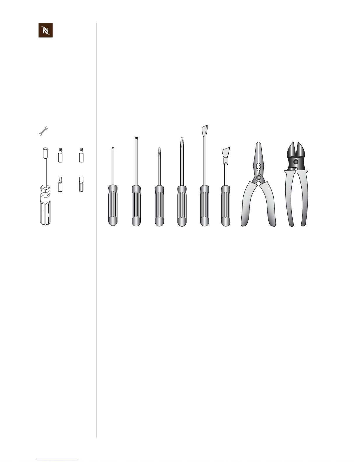
7.3 Tools and accessories
With the following assortment of tools, all repairs described can be made:
A bit holder with
appropriate bits can
also be used:
.
TX 15
TX 20
3.5 mm
8 mm
1) Torx screwdriver TX 15 / TX 20
2) Flat blade screwdrivers:
size blade width
00 2 mm
01 3,5 mm
05 8 mm
3) Disassembly tool (for housing parts,
EFR no. 0060611)
4) Pointed pliers
5) Side cutting pliers
6) Receptacle and towel to catch and
wipe away leaking water
1
2
3
TX 15
TX 20
3.5 mm
8 mm
4
2 mm
5
Page 31

Pixie service manual
31
REPAIRS
7.4 General disassembly
This subchapter shows
- how to replace the power cord,
- all necessary disassembly steps to gain access to the main assembly (brewing unit,
thermoblock, hydraulic unit and functional block.
7.4.1 Prepare coffee machine for disassembly
• Open closing handle to check if a capsule is in the brewing unit.
• Empty water system if hoses have to be detached for repair (see “Empty water
system” on page 19).
• Switch machine off.
• Disconnect power plug (40) and let coffee machine cool down.
• Remove all detachable parts from coffee machine
- waste water container (11) with cup support (12) and drip grid (13)
- capsule container (10)
- water tank with cover (5).
OFF
10
12
11
13
5
40
Page 32

Pixie service manual
32
REPAIRS
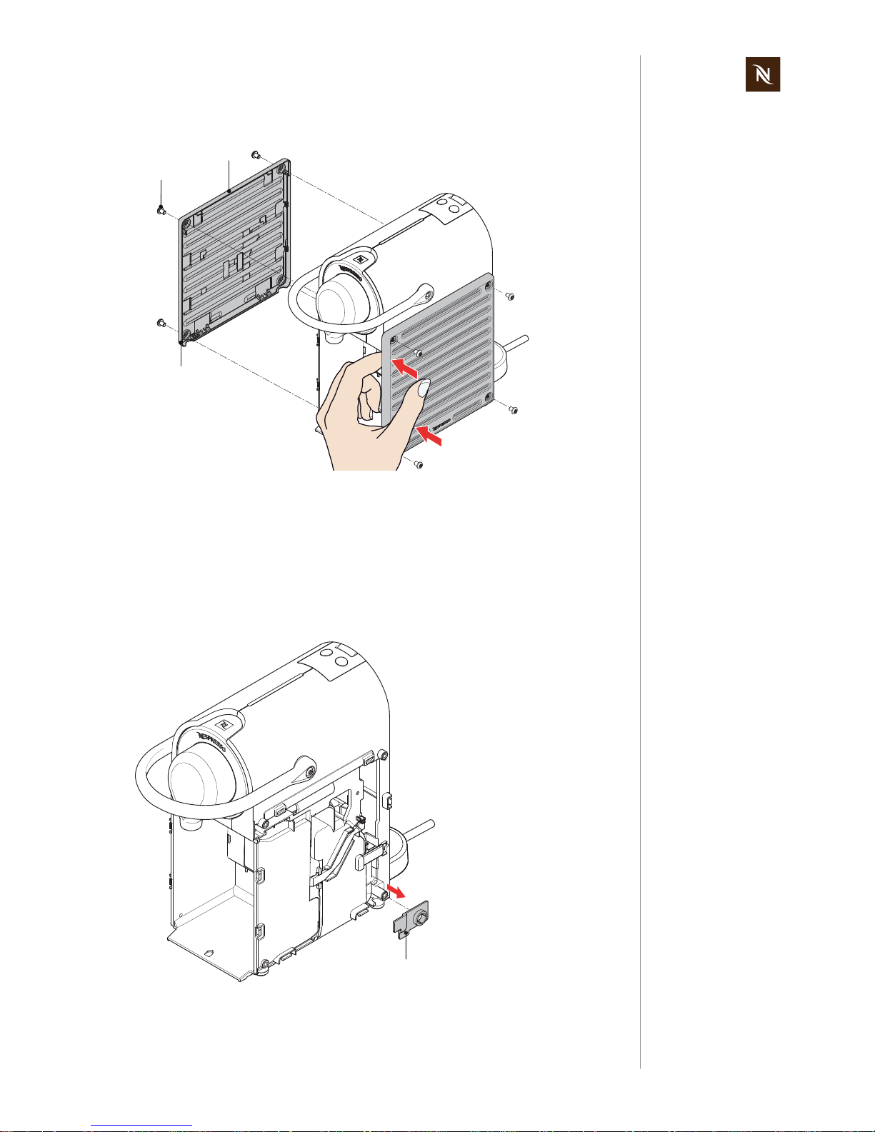
7.4.2 Remove side panels
• Loosen 4 screws (42, torx head TX 15) at each side panel (3).
• Use a screwdriver to release the latches at each side panel (3).
Start by inserting the srewdriver in the 2 semicircular cutouts at the bottom of a side
panel.
• After releasing the 2 latches at the bottom, swing up and remove side panel.
For replacing the
power cord, remove
right side panel only.
42
3
3
Take care not to
scratch the alumin-
ium surface and keep
the side panels at a safe
place.
3
3
Page 33
Pixie service manual
33
REPAIRS
Assembly checkpoints
• Both side panels (3) are identical and interchangeable.
• Position and press down side panel on housing of coffee machine.
• Press down leading edge (see arrows) of side panel additionally till a clicking noise
can be heard.
• Do not overtighten screws (42).
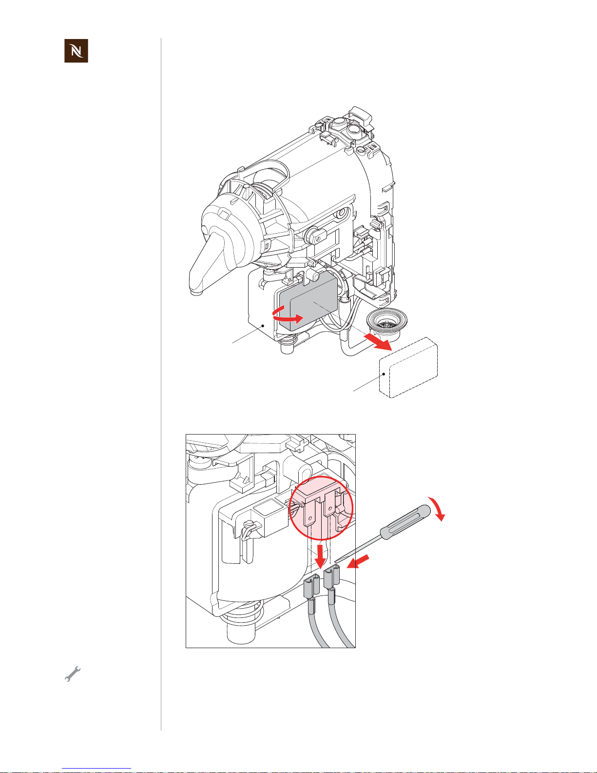
7.4.3 Remove power cord
• Remove cable protection (44).
3
3
42
44
Page 34

Pixie service manual
34
REPAIRS
• Unlatch strain relief clamp (39) with a 2 mm flat blade screwdriver.
• Disconnect ground wire (green/yellow) from thermoblock with pointed pliers.
• Lever out both insulated faston receptacles from electronic control board with a
screwdriver.
• Before removing the power cord (40), check if excessive cable length is retained in
right housing.
39
The strain relief
clamp is under ten-
sion. Therefore, hold
down the strain relief clamp
with your finger when
unlatching it.
40
Page 35

Pixie service manual
35
REPAIRS
Assembly checkpoints
• Only use the original spare part for replacing the country-specific power cord.
• Adjust power cord lenght to customer’s demand.
• Connect the insulated faston receptacles of neutral (N) and live (L) power cord wires
like shown above.
7.4.4 Remove water guiding
• Open brewing unit with closing handle (9).
• At first push up water guiding (8) and simultaneously pull out latch at the bottom with
the help of a screwdriver.
• Then push down again and remove water guiding (see detail).
Live (L)
Neutral (N)
Protective Earth
9
8
Page 36

Pixie service manual
36
REPAIRS
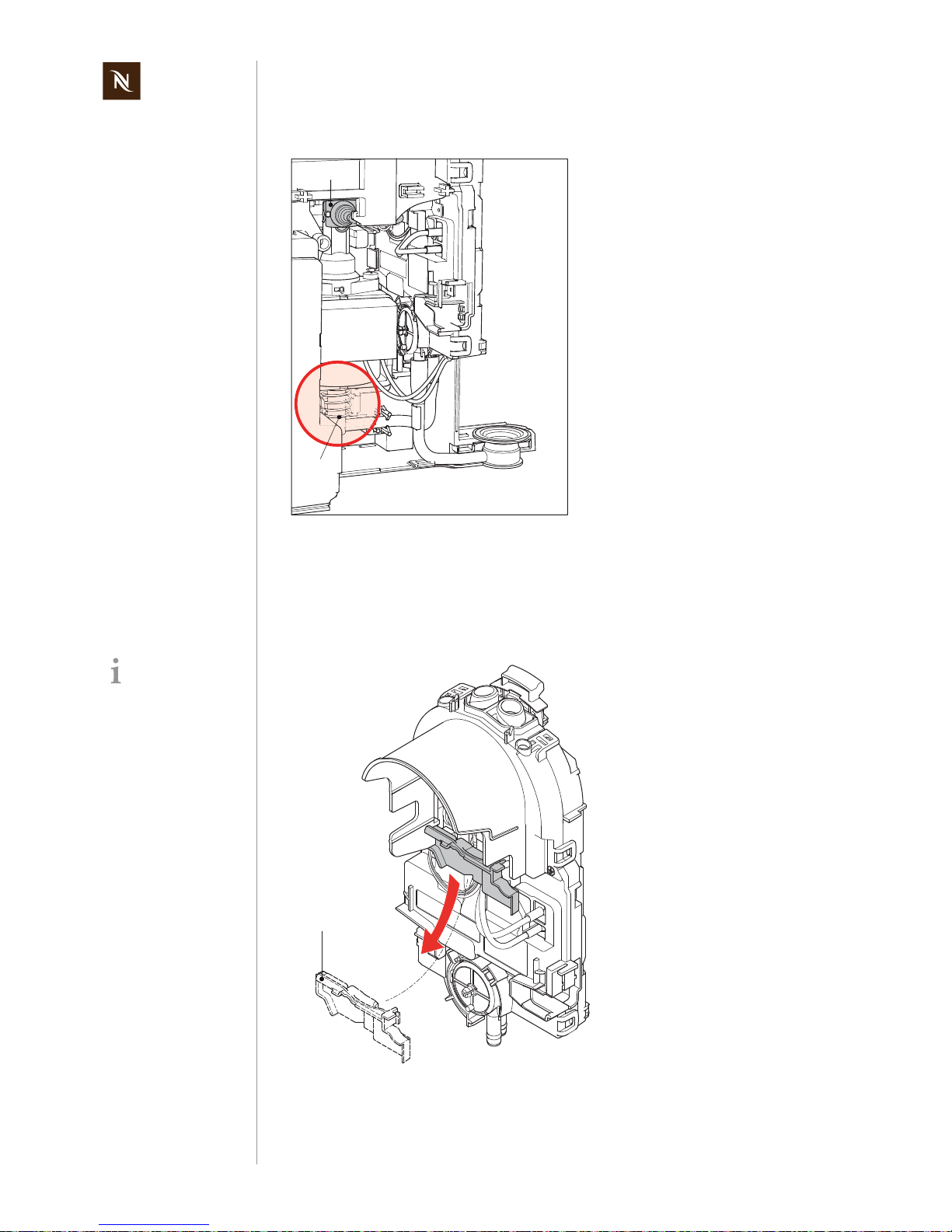
7.4.5 Remove damper springs
The brewing unit must be opened.
• Unhook both damper springs (19) with a screwdriver.
Assembly hint
• Attach damper spring (19) at hook on brewing unit housing.
• With the help of a small screwdriver attach the free eyelet of the spring to the
housing part.
19
19
The damper springs
are under tension.
Therefore, hold a
hand above for protection
when unhooking them.
19
Page 37

Pixie service manual
37
REPAIRS
7.4.6 Remove closing handle
• Close brewing unit.
• Hold closing handle (9) in one hand while loosening both screws (41, torx head
TX 20)
• Pull off closing handle from lever arms.
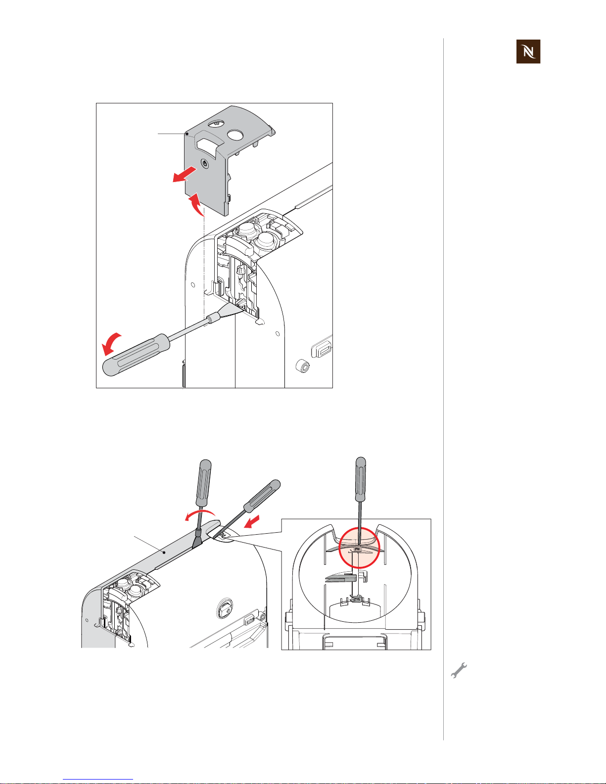
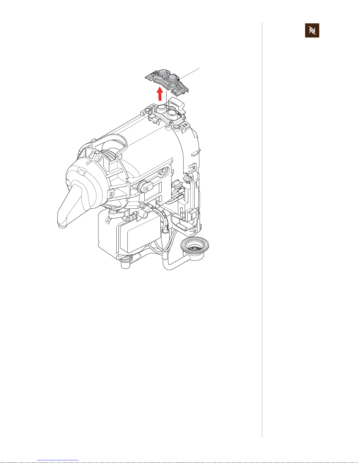
7.4.7 Remove cable cover
• Open 2 latches one after another with disassembly tool.
• Lift cable cover (6) and release remaining 2 latches at the front with a screwdriver if
necessary.
41
9
Take care, that both
lever arms stay in
horizontal position.
Otherwise, disassembling
of housing right is impossible.
Bottom view
6
Latches will break if
not unlocked very
carefully!
Page 38

Pixie service manual
38
REPAIRS
Assembly checkpoints
• Never re-use a damaged cable cover (6) with broken latches.
• Make sure that new cable cover is suitable for the cable diameter of the used power
cord.
7.4.8 Remove right light guide
• Release latch with screwdriver carefully.
• Swing up light guide (35) and remove it out of support.
Assembly checkpoint
• Handle fragile light guide carefully.
This step is necessary for the easy
removal of the right
housing part.
35
Page 39
Pixie service manual
39
REPAIRS
7.4.9 Remove blind
• Open latches with screwdriver and remove blind (7).
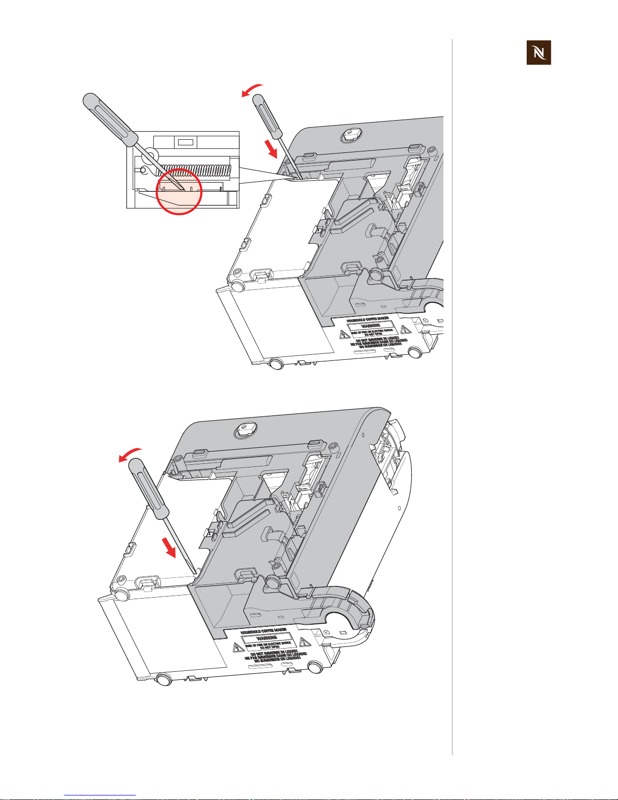
7.4.10 Remove housing right
• Position disassembly tool in gap at the front of housing right (2).
• Push down latch with a small screw driver.
• Then turn disassembly tool a bit to unlock the latch.
7
2
Latch will break if not
handled carefully!
Page 40

Pixie service manual
40
REPAIRS
• Position disassembly tool in gap at the rear of housing right (2).
• Push down latch with a small screw driver.
• Then turn disassembly tool a bit to unlock the latch.
• Open latch with screwdriver.
2
Latch will break if not
handled carefully!
Take care not to snap
the latches again by
accident, e.g. by
putting an object into the
gap.
Page 41
Pixie service manual
41
REPAIRS
• Open latch with screwdriver.
• Open latch with screwdriver.
Page 42

Pixie service manual
42
REPAIRS
• Press small screwdriver in opening. Lift housing right (2) simultaneously to release
latch.
• Press in screwdriver to open latch. Lift housing right (2) simultaneously to release
latch.
Detail view is from
above, showing the
latch position inside
of housing.
2
Upper detail view is
through opening into
empty housing.
2
Page 43

Pixie service manual
43
REPAIRS
• Push housings apart forcefully.
• If necessary, use disassembly tool to open remaining latches.
Assembly checkpoint
• Check if housing plate is mounted on housing left (1) before attaching housing right.
Detail view is through
rear opening from
above, showing
remaining closed latches.
1
Page 44

Pixie service manual
44
REPAIRS
7.4.11 Remove main assembly
• Remove housing plate from top of housing left (1).
The housing plate and a little magnet on the housing of the brewing unit lock the brewing
unit in the open position.
• Release latch of capsule cage with a small screwdriver and lift main assembly
slightly to open the latch.
1
Take care not to lose
this tiny part.
This latch does not
exist in new coffee
machines.
In case of a broken
latch it is not necessary to replace the
capsule cage.
Page 45

Pixie service manual
45
REPAIRS
• Pull water tank connector (33) out of support in housing left (1).
• Open latch with screwdriver and remove main assembly.
The main repair parts like brewing unit, thermoblock, pump and functional block are now
accessible.
33
1
Page 46

Pixie service manual
46
REPAIRS
7.4.12 Remove front ring
The front ring (15)
- is fixed on the brewing unit housing with 4 latches (2 at each side),
- has a detachable front cover (14).
• Press front ring (15) together at right side to release 2 latches.
• Simultaneously swivel front ring to the left to open these latches.
• Repeat same procedure at the left side and remove front ring.
14
15
A screwdriver can be
used instead..
Page 47
Pixie service manual
47
REPAIRS
7.4.13 Remove key caps of push buttons
• Remove key caps of push buttons (26) from main assembly.
Assembly checkpoints and hints
• Make sure that water tank connector (33) fits exactly in support of housing left.
• Press filter element down to bottom of water tank connector.
• Assemble spring (28) on pump support of housing left correctly.
26
Page 48
Pixie service manual
48
REPAIRS
7.5 Replacing pump
• Remove pump isolation (30) from pump (27).
• Disconnect cables from pump terminal.
30
27
Use pointed pliers or
a screwdriver to
remove receptacles.
Page 49

Pixie service manual
49
REPAIRS
• Remove low pressure hose (32)and pump support spring (28).
• Remove sound damper (29) from pump (27) and thermoblock (22) by cutting
connector clips (43) with side cutting pliers.
32
28
29
43
27
Page 50
Pixie service manual
50
REPAIRS
Assembly checkpoints
• Assemble spring (28) on pump support correctly.
• Sound damper (29) and connector clips (43) must always be replaced to prevent
leakage.
7.6 Replacing functional block
• Remove function block cap (25).
29+43
28
Brewing unit not
shown for better visibility of function block
cap (25).
25
Page 51

Pixie service manual
51
REPAIRS
• Unplug NTC connector and 2 receptacles from thermoblock with pointed pliers.
• Remove brewing unit (22) from functional block (24).
Brewing unit not
shown for better visibility of NTC connec-
tor.
24
22
Page 52

Pixie service manual
52
REPAIRS
Assembly checkpoint
• Connect the 2 receptacles like shown.
7.7 Replacing brewing unit
• To remove lever arms (18), press brewing unit housing (17) down against functional
block (24).
Wrong connection
will damage func-
tional block.
18
24
17
Page 53
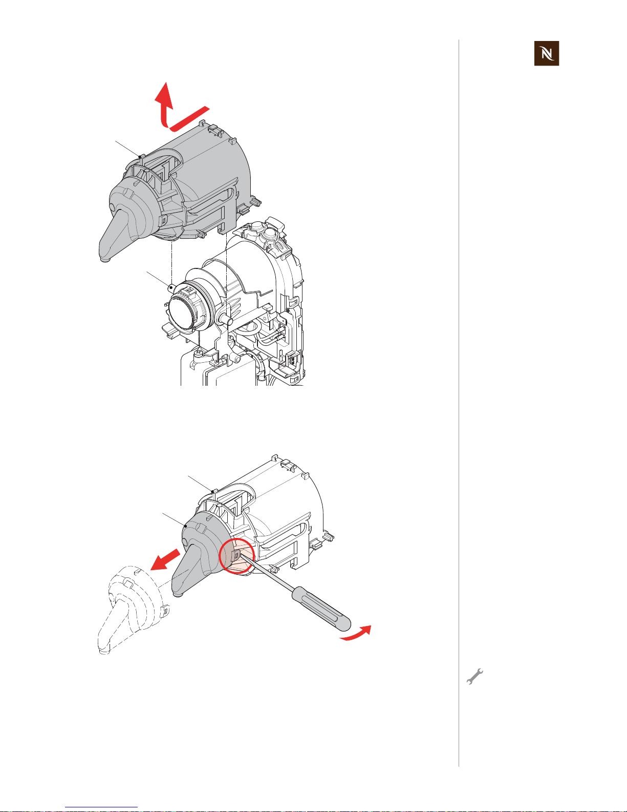
Pixie service manual
53
REPAIRS
• Pull away brewing unit housing (17) from thermoblock (22) up to the stop.
• Lift housing from thermoblock at right angels to release axle stubs from guiding
grooves.
• Remove steam cover (16) from brewing unit housing (17).
17
22
17
16
Handle latches carefully.
Page 54

Pixie service manual
54
REPAIRS
• Remove function block cap (25).
• Unplug NTC connector and 2 receptacles from thermoblock with pointed pliers.
Thermoblock not
shown for better visibility of function block
cap (25).
25
Thermoblock not
shown for better visibility of NTC connec-
tor.
Page 55

Pixie service manual
55
REPAIRS
.
• Remove thermoblock (21) from functional block (24).
21
24
Page 56
Pixie service manual
56
REPAIRS
Assembly checkpoints and hints
• Check that magnet is mounted on brewing unit housing (17).
• Connect the 2 faston receptacles like shown.
17
Wrong connection
will damage func-
tional block.
Page 57

Pixie service manual
57
REPAIRS
7.8 Replacing flow meter
• Remove hoses from flow meter (31).
• Insert screw driver in openings at the rear side of functional block (24, see detail).
• Unlatch and remove flow meter (31) from electronic main board.
Only functional block
is shown for better
visibility of hose con-
nections.
31
31
24
Page 58

Pixie service manual
58
REPAIRS
Assembly hints
• Always replace a removed flow meter (31) with a new one.
• Check correct mounting position of the hoses (32 and 33) on the flow meter (31).
By removing the flow
meter from the electronic main board its
latches get damaged.
31
32
33
Page 59

Pixie service manual
59
REPAIRS
7.9 Wiring diagrams
7.9.1 Wiring diagram 220 V - 240 V IEC
Depending on
national regulations,
one or two fine wire
fuses are mounted on the
thermoblock.
Small cup
On/Off Switch
Receptacle isolation
Big cup
Flow Meter
Main PCB
MMI PCB
Triac PCB
167°C
167°C
Thermoblock
Neutral
Line
Pump
EN4 220-240V
Overheat
protection
NTC
Triac
Page 60

Pixie service manual
60
REPAIRS
7.9.2 Wiring diagram 120 V UL (USA / Canada)
Small cup
On/Off Switch
Big cup
Flow Meter
Main PCB
MMI PCB
Triac PCB
167°C
Thermoblock
Neutral
Line
Pump
EN4 120-127V UL
Overheat
protection
Receptacle isolation
NTC
Triac
Page 61

Pixie service manual
61
REPAIRS
7.9.3 Wiring diagram 127 V IEC (Brazil)
Small cup
On/Off Switch
Receptacle isolation
Big cup
Flow Meter
Main PCB
MMI PCB
Triac PCB
167°C
167°C
Thermoblock
Neutral
Line
Pump
EN4 120-127V IEC
Overheat
protection
NTC
Triac
Page 62

Pixie service manual
62
REPAIRS
7.9.4 Wiring diagram 127 V IEC (Mexico)
Small cup
On/Off Switch
Receptacle isolation
Big cup
Flow Meter
Main PCB
MMI PCB
Triac PCB
167°C
167°C
Thermoblock
Neutral
Line
Pump
EN4 120-127V IEC
Overheat
protection
NTC
Triac
Page 63

Pixie service manual
63
REPAIRS
7.9.5 Wiring diagram 100 V IEC (Japan)
Small cup
On/Off Switch
Big cup
Flow Meter
Main PCB
MMI PCB
Triac PCB
167°C
Thermoblock
Neutral
Line
Pump
EN4 100-110V
Overheat
protection
167°C
Receptacle isolation
Page 64

Pixie service manual
64
REPAIRS
7.9.6 Wiring diagram 110 V IEC (Taiwan)
Small cup
On/Off Switch
Receptacle isolation
Big cup
Flow Meter
Main PCB
MMI PCB
Triac PCB
167°C
167°C
Thermoblock
Neutral
Line
Pump
EN4 100-110V
Overheat
protection
NTC
Triac
Page 65

Pixie service manual
65
FUNCTION TESTS
8 FUNCTION TESTS
8.1 Safety instructions
Some function tests are performed with an energized, partly opened coffee machine.
8.2 Required equipment
8.2.1 Overview
Danger of electrocution!
Mains voltage inside the coffee machine.
Do not touch any live part while performing tests.
Danger of burns!
Hot parts and water under pressure inside the coffee machine.
Do not touch any hot parts while checking for leakages!
Always wear protective goggles.
Symbolic illustration
of function test equip-
ment.
1) Pressure gauge (EFR no. 42213)
2) Pixie pressure gauge adapter
(EFR no. 66106), spare part seal
(EFR no. 64373)
3) Flashlight
4) Electronic thermometer
5) Timer
6) Measuring cup
7) Test equipment for protective earth continuity test and protective insulation test
T2
T1
RANGE
-200°C - 1370°C
-328°F - 2498°F
1
REL
HOLD
T1 T2
T1
←
T2
°C/°F
MAX MIN
1
2
5
4
6
3
7
MEASURE
LOCK/STOP
COMP
LIGHT
0Ω ADJ
Page 66

Pixie service manual
66
FUNCTION TESTS
8.2.2 Pressure gauge adapter
This pressure gauge adapter is designed for the Pixie coffee machine.
The pressure gauge adapter has 2 parts:
• A hand actuated lifting unit (1) to lock and seal the complete pressure gauge adapter
in the brewing unit.
• A seal carrier assembly (2) with a sealing cone that is inserted in the capsule cage
of the brewing unit.
1) Lifting unit
2) Seal carrier assembly
3) Operating lever
4) Fixation element
5) Quick action coupling for pressure
hose
6) Sealing cone
5
3
4
6
12
Page 67

Pixie service manual
67
FUNCTION TESTS
8.2.3 Mounting pressure gauge adapter
View into feed opening for capsule.
1) Open closing handle.
2) Insert seal carrier assembly.
3) Turn seal carrier assembly towards
capsule cage.
4) Align seal carrier to capsule cage. 5) Push back seal carrier assembly into
capsule cage.
6) Insert lifting unit. 7) Press down operating lever.
1
2
3
4
5
6
7
Page 68

Pixie service manual
68
FUNCTION TESTS
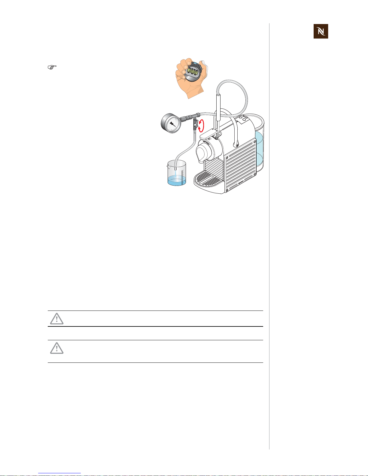
8.3 Measure flow rate
The pressure gauge
adapter must sit
firmly in the capsule
bay.
1) Fill and insert water tank.
2) Open closing handle.
3) Mount pressure gauge adapter (refer
to page 67).
4) Connect pressure hose to pressure
tester.
5) Place a measuring cup under the
drain hose of the pressure tester.
6) Switch on coffee machine.
7) After heating up, press the "large cup"
button.
8) Open the valve until water begins to
flow.
1
2
3
4
5
8
6
7
Page 69
Pixie service manual
69
FUNCTION TESTS
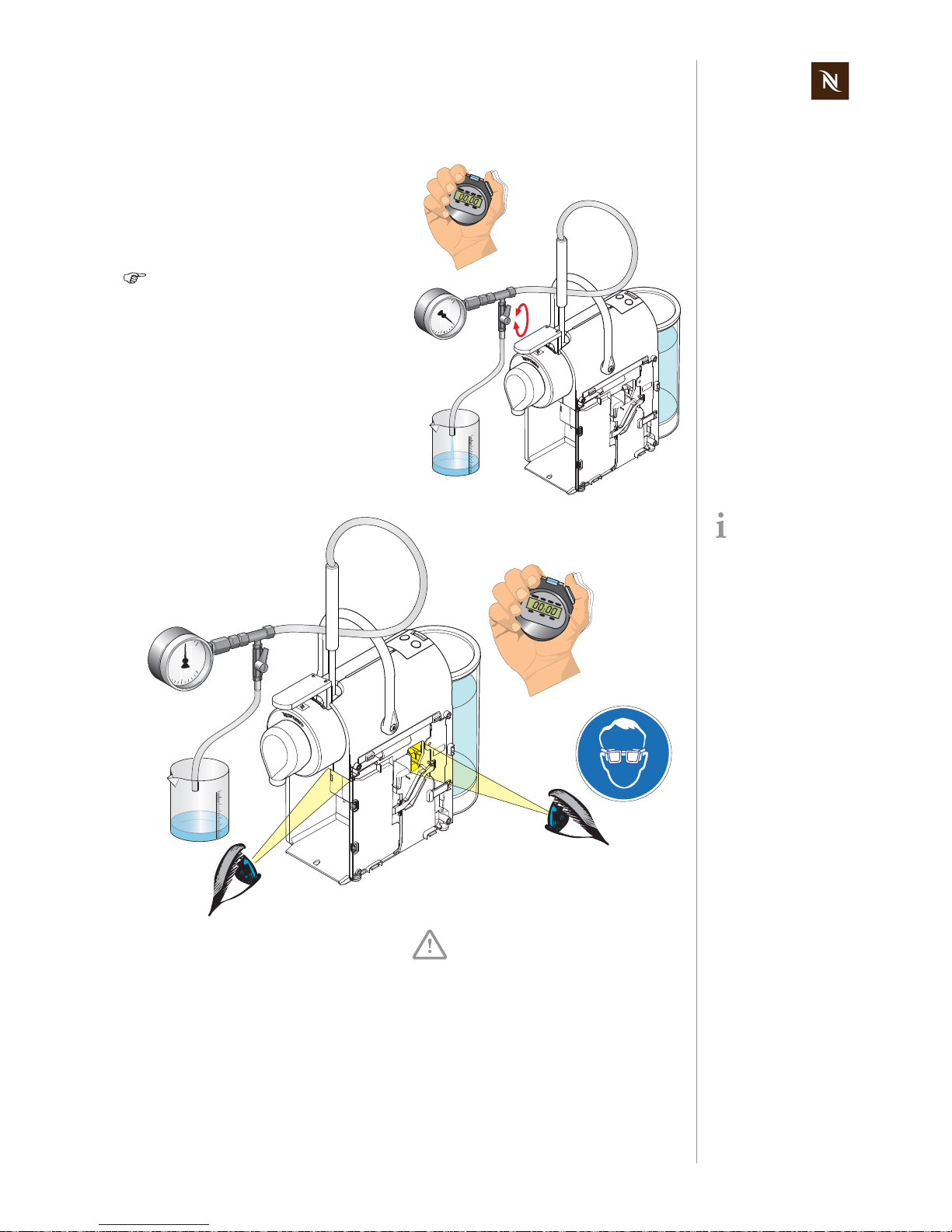
8.4 Pressure and leakage checks
Check the following parts of the coffee machine for leakages:
• Seal between movable part of brewing unit and capsule cage
• Connection between capsule cage and thermoblock (no visual check possible,
water will drop from thermoblock into housing)
• Both connections of sound damper
• Pump
9) Close the valve until the pressure
gauge indicates 12 bar.
Constantly monitor the pressure
gauge and if required readjust the
valve. As the temperature
increases, so does the pressure,
readjust the pressure to 12 bar
when required.
10) Carry out measurement for approx.
30 sec.
11) Control measuring cup: at least 60 120 ml of water must be in the measuring cup.
12) Open the valve and let water flow out
of the pressure tester.
Notices:
• Should < 60 ml leak out, then the pump
is defective or there is a leak in the
water system.
• Large deviations in indicated pressure
while measuring (± 4 bar) means that
the pump is defective.
Dangerous mains voltage inside the coffee machine!
Do not touch any parts under voltage while checking for leakages!
Dangerous hot parts under pressure inside the coffee machine!
Do not touch any hot/pressurized parts while checking for leakages!
Always wear protective goggles.
9 / 12
11
30 sec
> 60 ml
10
Page 70

Pixie service manual
70
FUNCTION TESTS
8.4.1 Preparations
1) Remove maintenace unit.
2) Remove right side panel (see “General
disassembly” on page 31).
3) Fill and insert water tank.
4) Open closing handle.
2
1
3
4
The pressure gauge
adapter must sit
firmly in the capsule
bay.
5) Mount pressure gauge adapter (refer
to page 67).
6) Connect pressure hose to pressure
tester.
7) Place a receptacle under the drain
hose of the pressure tester.
8) Connect mains cable.
9) Switch on coffee machine.
10) After heating up, press the "large cup"
button.
6
7
5
9
10
Page 71
Pixie service manual
71
FUNCTION TESTS
8.4.2 Test run
11) Open the valve and let the water flow
for approximately 10 sec out of the
drain hose.
12) Close the valve completely. The pressure stabilizes after increasing briefly
between 16-19 bar (pressure check).
The pressure increases slowly with
increasing temperature. Should the
pressure exceed 23 bar, switch off
the coffee machine and release the
pressure by opening the valve.
11/ 12
10 sec
For better visibility
use a flashlight.
13) Check connections under pressure for
audible and visible leaks
- through opening in right housing
- through opening for capsule ejection.
Do not run the pump for more
than 50 sec with the valve
closed.
13
max.
50 sec
13
Page 72
Pixie service manual
72
FUNCTION TESTS
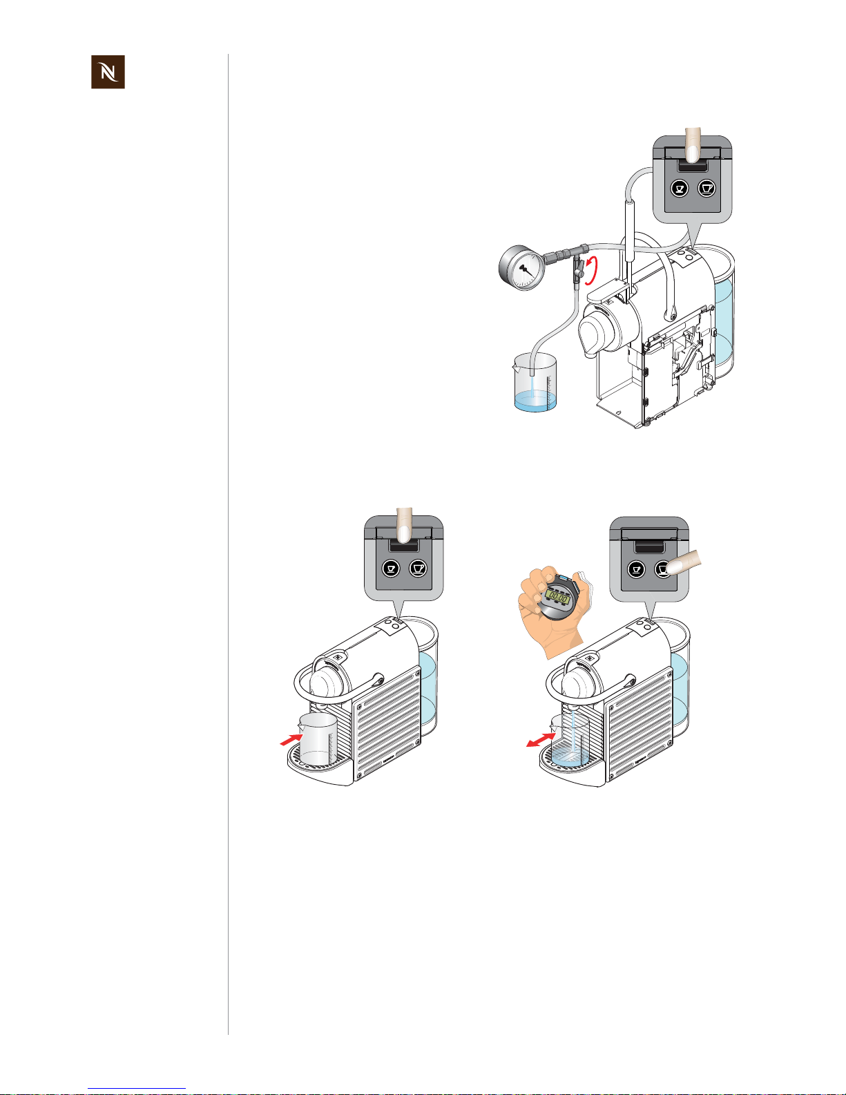
8.5 Measure coffee temperature
14) Switch off the coffee machine.
15) Open the valve and let water flow out
of the pressure tester.
16) Disconnect mains cable.
17) Remove pressure tester and water
tank.
18) Proceed with repair or remount right
side panel
1) Switch on coffee machine.
2) Place a measuring cup on cup support.
3) After heating up, press the "large cup"
button for approximately 10 sec to preheat the coffee outlet with hot water.
4) Empty measuring cup and place it
back on cup support.
15
14
2
1
4
3
10 sec
Page 73

Pixie service manual
73
FUNCTION TESTS
5) Insert capsule (Cosi is best suited).
6) Press the "large cup" button again.
7) Wait until the measuring cup contains
20 ml of coffee.
8) Then measure the coffee temperature
approx. 5-10 mm under the coffee outlet.
The coffee temperature should be
86 °C ± 3 °C (187 °F ± 5.4 °F).
5
6
5 - 10 mm
7
T2 T1
RANGE
-200°C - 1370°C
-328°F - 2498°F
1
REL
HOLD
T1 T2
T1
←
T2
°C/°F
MAX MIN
8
Page 74

Pixie service manual
74
FUNCTION TESTS
8.6 Protective earth (PE) continuity test
8.6.1 What is the protective earth continuity test about?
This test is only necessary
- for class 1 equipment (three-wire power cord with protective earth)
- after a repair whenever a general disassembly was performed.
Therefore all Pixie models have to be tested after general disassembly, except countryspecific models (USA, Canada, Japan) without a protective earth connection (refer to
"Wiring diagrams" on page 59 and following).
8.6.2 General
Legal regulation
In case of a repair/modification of the coffee machine, the repair centre is bound by law
to protect the user/consumer by
- restoring the regular condition of the appliance and
- performing the respective tests according to EN/IEC 60335-1 “Safety of household
and similar electrical appliances” and national regulations (e.g. DIN VDE 0701).
Description
Protective earth continuity measurements are made between the protective earth
terminal of the power plug and the thermoblock casing.
This test assures that
- the ground (earth) connection does not have an interruption between the power plug
and the thermoblock
- the permissible ground resistance is less than 0.3 Ohms (with a test current of
200 mA DC).
Test equipment
Special test equipment is needed that complies with the regulations to perform protective earth continuity measurements. Detailed requirements and tolerances must be verified by your local authorities or measurement supplier in any case.
Test report
For legal reasons a repair or test report should be prepared and filed with following information
- customer (name, address)
- type and serial number of coffee machine
- date of repair/test(s)
- performed test(s)/measuring value(s)
- used test equipment
- signature
Ask Nespresso for
recommendations
about test equipment.
Page 75

Pixie service manual
75
FUNCTION TESTS
8.6.3 Test sequence
This test sequence is
not applicable for cof-
fee machines with
two-wire power cords (without ground pin).
Danger of electrocution!
Do not plug in the coffee machine during the protective earth continuity
test.
Read and observe safety instructions in user manual of test equipment.
Symbolic illustration
of test equipment.
1) Connect black measuring cable to
ground pin of power plug with an alligator clip (example shown: Swiss
power plug).
2) Switch on test equipment and select
protective earth continuity test.
MEASURE
LOCK/STOP
COMP
LIGHT
0Ω ADJ
By looking into the
casule ejection slot
form below, metallic
parts of the thermoblock
are visible on both sides of
the capsule cage.
3) Remove water tank.
4) Remove maintenance unit.
5) Open closing handle.
6) Insert tip of red test probe up into capsule ejection slot and touch thermoblock.
7) Press "measure" button and read off
displayed resistance.
The resistance must be lower than
0.3 Ohm.
8) Fill in measured value in a test report.
5
4
3
7
MEASURE
LOCK/STOP
COMP
LIGHT
0Ω ADJ
0.215 Ohm
Test passed
6
Page 76

Pixie service manual
76
FUNCTION TESTS
8.6.4 What to do if the protective earth continuity test fails
• Check/measure ground wire connection of power cord; replace if necessary.
• Check/measure ground connection terminal on thermoblock. Retighten terminal
screw if necessary.
8.7 Protective insulation test
8.7.1 What is the protective insulation test about?
This test is necessary
- for class 1 and 2 equipment (with/without protective earth)
- after a repair whenever a general disassembly was performed.
8.7.2 General
Legal regulation
In case of a repair/modification of the coffee machine, the repair centre is bound by law
to protect the user/consumer by
- restoring the regular condition of the appliance and
- performing the respective tests according to EN/IEC 60335-1 “Safety of household
and similar electrical appliances” and national regulations (e.g. DIN VDE 0701).
Description
The insulation test
- assures that wiring and insulation of the coffee machine fullfill the normative requirements after a repair,
- rates the insulation capability of the coffee machine,
- is a very dangerous test because of a high test voltage (500 V DC).
For the insulation test, phase and neutral wire are shunted at the power plug. Then a
test voltage is applied between phase/neutral and selected parts of the coffee machine.
Test equipment
Special test equipment is needed that complies with the regulations to perform insulation
and withstanding voltage tests. Detailed requirements and tolerances must be verified
with your local authorities or measurement supplier in any case.
Ideally the test equipment has a national power socket for testing, so that the coffee
machine can plugged in directly. Otherwise a special shunt is necessary to connect the
phase and neutral pin of the coffee machine’s power plug.
Test report
For legal reasons a repair or test report should be prepared and filed with following information
- customer (name, address)
- type and serial number of coffee machine
- date of repair/test(s)
Perform the protective earth (PE) continuity test at first, if it is
mandatory.
Ask Nespresso for
recommendations
about test equipment.
Page 77

Pixie service manual
77
FUNCTION TESTS
- performed test(s)/measuring value(s), test points
- used test equipment
- signature
8.7.3 Test sequence
Danger of electrical shock/short circuit!
Do not plug in the coffee machine during insulation test.
Danger of electrical shock!
Do not touch tip of test probes.
Do not touch metallic parts of coffee machine during test.
Read and observe safety instructions in user manual of test equipment.
A Swiss power plug is
shown here as an
example.
Use a short circuit
plug or special alligator clips etc. as sub-
stitute for this test adapter.
1) Connect the phase and neutral pin of
the power plug together with a test
adapter (procured by the repair
centre).
2) Connect the black measuring cable to
the test adapter (see image).
3) Switch on coffee machine.
Symbolic illustration
of test equipment.
4) Switch on test equipment and select
an insulation test voltage of 500 V DC.
MEASURE
LOCK/STOP
COMP
LIGHT
0Ω ADJ
Some test equipment
displays test passed
or failed instead of
the insulation resistance.
5) Touch right side panel with red test
probe.
6) Press "measure" button.
7) Read off displayed insulation resistance or test result.
8) Test left side panel in the same way.
The insulation resistance must
always be higher than 300 kOhm
(300,000 Ohm).
6
Test passed
5
Page 78

Pixie service manual
78
FUNCTION TESTS
8.7.4 What to do if the insulation test fails
• Assume that the coffee machine is defect after a failed insulation test.
• Check wiring and locate fault. After fault clearance proceed with troubleshooting
check list (see page 26).
By looking into the
capsule ejection slot
form below, metallic
parts of the thermoblock
are visible on both sides of
the capsule cage.
9) Touch closing handle with red test
probe.
10) Press "measure" button.
11) Read off displayed insulation resistance or test result.
12) Insert tip of red test probe up into capsule ejection slot and touch thermoblock.
13) Press "measure" button.
14) Read off displayed insulation resistance or test result.
The insulation resistance must be
always higher than 300 kOhm
(300’000 Ohm).
15) Switch off test equipment.
16) Short red with black test probe to
make sure that test voltage is discharged.
17) Fill in results in a test report.
Risk of damage!
A sparkover can damage the electronic control board etc.
10
Test passed
9
12
Page 79

Pixie service manual
79
EXPLOSION DRAWINGS
9 EXPLOSION DRAWINGS
9.1 EF 280 Explosion drawing
Page 80

Pixie service manual
80
EXPLOSION DRAWINGS
9.2 EF 281 Explosion drawing
Page 81

Pixie service manual
81
PARTS LIST
10 PARTS LIST
10.1 Nespresso EF 280 / C60 and EF 281 / D60
Pos. Part no. Component Remark
1 0067948 Spare holder 280 left mount.
2 0062590 Holder 280 right, black
3 0067953 Spare side wall 281
light blue, packed, 2 pcs. (D60 EU steel
blue, D60 ZA steel blue)
3 0067958 Spare side wall 280
titanium, packed, 2 pcs. (C60 EU titan,
C60 IL titan, C60 SA titan)
3 0067959 Spare side wall 280
red, packed, 2 pcs., (C60 EU red, C60 IL
red, C60 SA red, C60 ZA red)
3 0067960 Spare side wall 280
blue, packed, 2 pcs. (C60 EU indigo,
C60 SA indigo, C60 IL indigo, C60 ZA
idigo)
3 0067961 Spare side wall 281
alu, packed, 2 pcs. (D60 EU alu, D60 ZA
alu)
3 0067962 Spare side wall 281 yellow, packed, 2 pcs. (D60 ZA lime)
4 0000394 Rubber feet 10.0 x 1.6mm black SJ-5816
5 0067944 Spare water tank 280 cpl. packed,6 pcs.
6 0062621 Cover 280 cable EU black
7 0063073 Cover 280 switch black
8 0062821 Guide 280 water black
9 0062787 Lock rod 280 chrom.
10 0062592 Caps contain 280 transp.
11 0067946 Spare drip tray 280 packed
12 0062616 Cup shelf 280 black
13 0067869 Drip plate 280 cpl. mount. SK
13 0067881 Drip plate 281 cpl. mount. SK
14 0062641 Cover 280 outlet black
14 0062599 Cover 281 outlet black
15 0062598 Faceplate 280 outlet, black
16 0062589 Outlet 280 neutral
17 0062977 Casing 280 NBU cpl. mount.
18 0063218 Knee-lever 280 NBU cpl. mount.
19 0062808
Tension spring
D = 0,4 x 5,0 x 24,0
Inox
22 0067949 Spare thermobl. 280 230V IEC mount.
23 0061701 O-Ring 3,40 x 1,90 EPDM V3 70 Shore black
24 0067942 Spare electronic 280 230V packed
25 0066981 Cover 280 electronic V2 black
26 0062799 Push-button 280 2x print: symb, black
27 0067957 Spare pump 280 230V IEC mount.
28 0062806 Press. spring 1,10 / Dm 15,00
L=19,7 n=4,5 inox ends flaten /
smoothed
29 0065983 Press. hose 280 cpl. mount. damper, pump-TB
30 0062774 Cover 280 pump black
31 0063063 Flow meter NNSA FM cpl.
32 0062783 Molded tube 280 pump transp., 60 Shore
Page 82

Pixie service manual
82
PARTS LIST
33 0067947 Spare valve lifter 280 packed
34 0062632 Light cond. 280 right transp. caps contain.
36 0062631 Light cond. 280 left transp. caps contain.
37 0062628 Light cond. 280 receiver transp. level indicator
38 0062629 Light cond. 280 LED transp. level indicator
39 0062617 Strain relief clamp 280 EU neutral
40 0062812 Line cord M36
H05VV-F3G075/L40/N40/PE95,
assembled (for EU)
40 0063122 Line cord M69
H05VV-F3G075/L40/N40/PE95,
assembled (for SA)
40 0064789 Line cord SF-968
H05VV-F3G0,75/L40/N40/PE95,
assembled (for IL)
40 0064793 Line cord M65
H05VV-F3G0,75/L40/N40/PE95,
assembled (for ZA)
41 0062814
Screw KST/PT
4,0 x 13 bl. galvan.
rd. head Torx-20 (SFS-Remform)
42 0062813
Screw KST/PT
4,0 x 6 bl. galvan.
rd. head Torx-15 (SFS-Remform)
43 0063142 Spring clip d=8,0 x 1,0mm Inox
44 0068151 Cable protect. 280 black
Pos. Part no. Component Remark
Page 83

Pixie service manual
83
PARTS LIST
10.2 208 Turmix TX160 CH
Pos. Part no. Component Remark
1 0067948 Spare holder 280 left mount.
2 0062590 Holder 280 right, black
3 0067960 Spare side wall 280 blue, packed, 2 pcs.
4 0000394 Rubber feet 10.0 x 1.6mm black SJ-5816
5 0067944 Spare water tank 280 cpl. packed, 6 pcs.
6 0062621 Cover 280 cable EU black
7 0064905 Cover 280 Turmix print: silver
8 0062821 Guide 280 water black
9 0062787 Lock rod 280 chrom.
10 0062592 Caps. contain 280 transp.
11 0067946 Spare drip tray 280 packed
12 0062616 Cup shelf 280 black
13 0067869 Drip plate 280 cpl mount. SK
14 0062641 Cover 280 outlet black
15 0062598 Faceplate 280 outlet, black
16 0062589 Outlet 280 neutral
17 0062977 Casing 280 NBU cpl. mount.
18 0063218 Knee-lever 280 NBU cpl. mount.
19 0062808 Tension spring D = 0,4 x 5,0 x 24,0 Inox
22 0067949 Spare thermobl. 280 230V IEC mount.
23 0061701 O-Ring 3,40 x 1,90 EPDM V3 70 Shore black
24 0067942 Spare electronic 280 230V packed
25 0066981 Cover 280 electronic V2 black
26 0062799 Push-button 280 2x print: symb., black
27 0067957 Spare pump 280 230V IEC mount.
28 0062806 Press. spring 1,10 / Dm 15,00
L=19,7 n=4,5 inox ends flaten./
smoothed
29 0065983 Press. hose 280 cpl. mount. damper, pump-TB
30 0062774 Cover 280 pump black
31 0063063 Flow meter NNSA FM cpl.
32 0062783 Molded tube 280 pump transp., 60 Shore
33 0067947 Spare valve lifter 280 packed
34 0062632 Light cond. 280 right transp. caps contain
36 0062631 Light cond. 280 left transp. caps contain
37 0062628 Light cond. 280 receiver transp. level indicator
38 0062629 Light cond. 280 LED transp. level indicator
39 0062617 Strain relief clamp 280 EU neutral
40 0063121 Line cord M12
H05VV-F3G075/L40/N40/PE95,
assembled
41 0062814 Screw KST/PT 4,0x13 bl. galvan. rd. head Torx-20 (SFS-Remform)
42 0062813 Screw KST/PT 4,0x 6 bl. galvan. rd. head Torx-15 (SFS-Remform)
43 0063142 Spring clip d = 8,0 x 1,0mm Inox
44 0068151 Cable protect. 280 black
Page 84

Pixie service manual
84
PARTS LIST
10.3 281 DeLonghi EN125 EU
Pos. Part no. Component Remark
1 0067948 Spare holder 280 left mount.
2 0062590 Holder 280 right, black
3 0067961 Spare side wall 281 alu, packed, 2 pcs.
4 0000394 Rubber feet 10.0 x 1.6mm black SJ-5816
5 0067944 Spare water tank 280 cpl. packed, 6 pcs.
6 0062621 Cover 280 cable EU black
7 0064906 Cover 281 DeLonghi print: silver
8 0062821 Guide 280 water black
9 0062787 Lock rod 280 chrom.
10 0062592 Caps. contain 280 transp.
11 0067946 Spare drip tray 280 packed
12 0062616 Cup shelf 280 black
13 0067881 Drip plate 281 cpl. mount. SK
14 0062599 Cover 281 outlet black
15 0062598 Faceplate 280 outlet, black
16 0062589 Outlet 280 neutral
17 0062977 Casing 280 NBU cpl. mount.
18 0063218 Knee-lever 280 NBU cpl. mount.
19 0062808 Tension spring D = 0,4 x 5,0 x 24,0 Inox
22 0067949 Spare thermobl. 280 230V IEC mount.
23 0061701 O-Ring 3,40 x 1,90 EPDM V3 70 Shore black
24 0067942 Spare electronic 280 230V packed
25 0066981 Cover 280 electronic V2 black
26 0062799 Push-button 280 2x print: symb, black
27 0067957 Spare pump 280 230V IEC mount.
28 0062806 Press. spring 1,10 / Dm 15,00
L=19,7 n=4,5 inox ends flaten /
smoothed
29 0065983 Press. hose 280 cpl. mount. damper, pump-TB
30 0062774 Cover 280 pump black
31 0063063 Flow meter NNSA FM cpl.
32 0062783 Molded tube 280 pump transp, 60 Shore
33 0067947 Spare valve lifter 280 packed
34 0062632 Light cond. 280 right transp. caps. contain.
36 0062631 Light cond. 280 left transp. caps. contain.
37 0062628 Light cond. 280 receiver transp. level indicator
38 0062629 Light cond. 280 LED transp. level indicator
39 0062617 Strain relief clamp 280 EU neutral
40 0062812 Line cord M36
H05VV-F3G075/L40/N40/PE95,
assembled
41 0062814 Screw KST/PT 4,0 x 13 bl. galvan. rd. head Torx-20 (SFS-Remform)
42 0062813 Screw KST/PT 4,0 x 6 bl. galvan. rd. head Torx-15 (SFS-Remform)
43 0063142 Spring clip d = 8,0 x 1,0mm Inox
44 0068151 Cable protect. 280 black
Page 85

Pixie service manual
85
PARTS LIST
10.4 280 Krups XN300510 EU
Pos. Part no. Component Remark
1 0067948 Spare holder 280 left mount.
2 0062590 Holder 280 right, black
3 0067958 Spare side wall 280 titanium, packed, 2 pcs.
4 0000394 Rubber feet 10.0 x 1.6mm black SJ-5816
5 0067944 Spare water tank 280 cpl. packed, 6 pcs.
6 0062621 Cover 280 cable EU black
7 0064904 Cover 280 Krups print: silver
8 0062821 Guide 280 water black
9 0062787 Lock rod 280 chrom.
10 0062592 Caps. contain. 280 transp.
11 0067946 Spare drip tray 280 packed
12 0062616 Cup shelf 280 black
13 0067869 Drip plate 280 cpl. mount.SK
14 0062641 Cover 280 outlet black
15 0062598 Faceplate 280 outlet, black
16 0062589 Outlet 280 neutral
17 0062977 Casing 280 NBU cpl. mount.
18 0063218 Knee-lever 280 NBU cpl. mount.
19 0062808 Tension spring D = 0,4 x 5,0 x 24,0 Inox
22 0067949 Spare thermobl. 280 230V IEC mount.
23 0061701 O-Ring 3,40 x 1,90 EPDM V3 70 Shore black
24 0067942 Spare electronic 280 230V packed
25 0066981 Cover 280 electronic V2 black
26 0062799 Push-button 280 2x print: symb, black
27 0067957 Spare pump 280 230V IEC mount.
28 0062806 Press. spring 1,10 / Dm 15,00
L=19,7 n=4,5 inox ends flaten./
smoothed
29 0065983 Press. hose 280 cpl. mount. damper, pump-TB
30 0062774 Cover 280 pump black
31 0063063 Flow meter NNSA FM cpl.
32 0062783 Molded tube 280 pump transp, 60 Shore
33 0067947 Spare valve lifter 280 packed
34 0062632 Light cond. 280 right transp. caps. contain.
36 0062631 Light cond. 280 left transp. caps. contain.
37 0062628 Light cond. 280 receiver transp. level indicator
38 0062629 Light cond. 280 LED transp. level indicator
39 0062617 Strain relief clamp 280 EU neutral
40 0062812 Line cord M36
H05VV-F3G075/L40/N40/PE95,
assembled
41 0062814 Screw KST/PT 4,0 x 13 bl. galvan. rd. head Torx-20 (SFS-Remform)
42 0062813 Screw KST/PT 4,0 x 6 bl. galvan. rd. head Torx-15 (SFS-Remform)
43 0063142 Spring clip d = 8,0 x 1,0mm Inox
44 0068151 Cable protect. 280 black
Page 86

Pixie service manual
86
PARTS LIST
10.5 281 Magimix M110 EU/GB
Pos. Part no. Component Remark
1 0067948 Spare holder 280 left mount.
2 0062590 Holder 280 right, black
3 0067961 Spare side wall 281 alu, packed, 2 pcs. (EU)
3 0067953 Spare side wall 281 light blue, packed, 2 pcs. (GB)
4 0000394 Rubber feet 10.0 x 1.6mm black SJ-5816
5 0067944 Spare water tank 280 cpl. packed, 6 pcs.
6 0062621 Cover 280 cable EU black
7 0064908 Cover 281 Magimix print: silver
8 0062821 Guide 280 water black
9 0062787 Lock rod 280 chrom.
10 0062592 Caps. contain. 280 transp.
11 0067946 Spare drip tray 280 packed
12 0062616 Cup shelf 280 black
13 0067881 Drip plate 281 cpl. mount. SK
14 0062599 Cover 281 outlet black
15 0062598 Faceplate 280 outlet, black
16 0062589 Outlet 280 neutral
17 0062977 Casing 280 NBU cpl. mount.
18 0063218 Knee-lever 280 NBU cpl. mount.
19 0062808 Tension spring D = 0,4 x 5,0 x 24,0 Inox
22 0067949 Spare thermobl. 280 230V IEC mount.
23 0061701 O-Ring 3,40 x 1,90 EPDM V3 70 Shore black
24 0067942 Spare electronic 280 230V packed
25 0066981 Cover 280 electronic V2 black
26 0062799 Push-button 280 2x print:symb,black
27 0067957 Spare pump 280 230V IEC mount.
28 0062806 Press. spring 1,10 / Dm 15,00
L = 19,7 n=4,5 inox ends flaten./
smoothed
29 0065983 Press. hose 280 cpl. mount. damper, pump-TB
30 0062774 Cover 280 pump black
31 0063063 Flow meter NNSA FM cpl.
32 0062783 Molded tube 280 pump transp., 60 Shore
33 0067947 Spare valve lifter 280 packed
34 0062632 Light cond. 280 right transp. caps. contain.
36 0062631 Light cond. 280 left transp. caps. contain.
37 0062628 Light cond. 280 receiver transp. level indicator
38 0062629 Light cond. 280 LED transp. level indicator
39 0062617 Strain relief clamp 280 EU neutral
40 0062812 Line cord M36
H05VV-F3G075/L40/N40/PE95,
assembled (EU)
40 0063122 Line cord M69
H05VV-F3G075/L40/N40/PE95,
assembled (GB)
41 0062814 Screw KST/PT 4,0 x 13 bl. galvan. rd. head Torx-20 (SFS-Remform)
42 0062813 Screw KST/PT 4,0 x 6 bl. galvan. rd. head Torx-15 (SFS-Remform)
43 0063142 Spring clip d = 8,0 x 1,0mm Inox
44 0068151 Cable protect. 280 black
Page 87

Pixie service manual
87
PARTS LIST
10.6 281 Koenig D60 CH
Pos. Part no. Component Remark
1 0067948 Spare holder 280 left mount.
2 0062590 Holder 280 right, black
3 0067962 Spare side wall 281 yellow, packed, 2 pcs.
4 0000394 Rubber feet 10.0 x 1.6mm black SJ-5816
5 0067944 Spare water tank 280 cpl. packed, 6 pcs.
6 0062621 Cover 280 cable EU black
7 0064907 Cover 281 Koenig print: silver
8 0062821 Guide 280 water black
9 0062787 Lock rod 280 chrom.
10 0062592 Caps. contain. 280 transp.
11 0067946 Spare drip tray 280 packed
12 0062616 Cup shelf 280 black
13 0067881 Drip plate 281 cpl mount. SK
14 0062599 Cover 281 outlet black
15 0062598 Faceplate 280 outlet, black
16 0062589 Outlet 280 neutral
17 0062977 Casing 280 NBU cpl. mount.
18 0063218 Knee-lever 280 NBU cpl. mount.
19 0062808 Tension spring D = 0,4 x 5,0 x 24,0 Inox
22 0067949 Spare thermobl. 280 230V IEC mount.
23 0061701 O-Ring 3,40 x 1,90 EPDM V3 70 Shore black
24 0067942 Spare electronic 280 230V packed
25 0066981 Cover 280 electronic V2 black
26 0062799 Push-button 280 2x print: symb, black
27 0067957 Spare pump 280 230V IEC mount.
28 0062806 Press. spring 1,10 / Dm 15,00
L = 19,7 n=4,5 inox ends flaten./
smoothed
29 0065983 Press. hose 280 cpl. mount. damper, pump-TB
30 0062774 Cover 280 pump black
31 0063063 Flow meter NNSA FM cpl
32 0062783 Molded tube 280 pump transp., 60 Shore
33 0067947 Spare valve lifter 280 packed
34 0062632 Light cond. 280 right transp. caps. contain.
36 0062631 Light cond. 280 left transp. caps. contain.
37 0062628 Light cond. 280 receiver transp. level indicator
38 0062629 Light cond. 280 LED transp. level indicator
39 0062617 Strain relief clamp 280 EU neutral
40 0063121 Line cord M12
H05VV-F3G075/L40/N40/PE95,
assembled
41 0062814 Screw KST/PT 4,0 x 13 bl. galvan. rd. head Torx-20 (SFS-Remform)
42 0062813 Screw KST/PT 4,0 x 6 bl. galvan. rd. head Torx-15 (SFS-Remform)
43 0063142 Spring clip d = 8,0 x 1,0mm Inox
44 0068151 Cable protect. 280 black
Page 88

Pixie service manual
88
NOTES
11 NOTES
 Loading...