

NEFF T26S56N0/01 Installation Instruction
bitte aufbewahren
veuillez conserver
si prega di conservarle
please keep
por favor, guardar
por favor, guardar
lütfen saklayýnýz
Assembly instructions
Einbauanleitung
Notice de montage
Istruzioni di Montaggio
Instrucciones de montaje
Montaj talimatlarý
Руководство по монтажу
s.v.p. bewaren
Installatievoorschrift
~
.
-
.
29
19
~26
~50
1
PL
Instrukcja montażu
пожалуйста, сохраните данное руководство
zachować
en
de
fr
Instruções de montagem
pt
nl
tr
it
es
582
520
520
ru
pl
702
3
2
4
5
5a
6
7
7 a
8
9
8 a

en
Read the appliance's instructions before
installing and using.
The graphics in these Assembly
instructions are given as a guide only.
The manufacturer is exempt from all
liability if this manual's requirements
are not complied with.
Safety instructions
All installation, regulation and
adaptation to other types of gas must
be carried out by an authorised
installation technician, respecting all
applicable regulations, standards
and the country's electrical and gas
supply companies' specifications.
It is recommended that you call our
Technical Assistance Service for
adaptation to other types of gas.
Before you begin, turn off the
appliance's electricity and gas
supply.
This appliance has been designed for
home use only. This appliance cannot
be installed on yachts or in caravans.
Before installing, you need to check that
local distribution conditions (gas type
and pressure) and the appliance's
adjustment are compatible (see table I).
The appliance's adjustment conditions
are written on the label or the
specifications plate.
This appliance can only be installed in a
well-ventilated place in accordance with
existing regulations and ventilation
specifications. The appliance must not
be connected to a combustion product
evacuation device.
The supply cable must be attached to
the unit to prevent it from touching hot
parts of the oven or hob.
Appliances with electrical supply must
be earthed.
Do not tamper with the appliance's
interior. If necessary, call our Technical
Assistance Service.
Before installing
This appliance is class 3 type, according
to the EN 30-1-1 regulation for gas
appliances: built-in appliance.
The units next to the appliance must be
made of non-flammable materials. The
laminated covering and glue for
adhering it must be heat resistant.
This appliance cannot be installed
above fridges, washing machines,
dishwashers or similar.
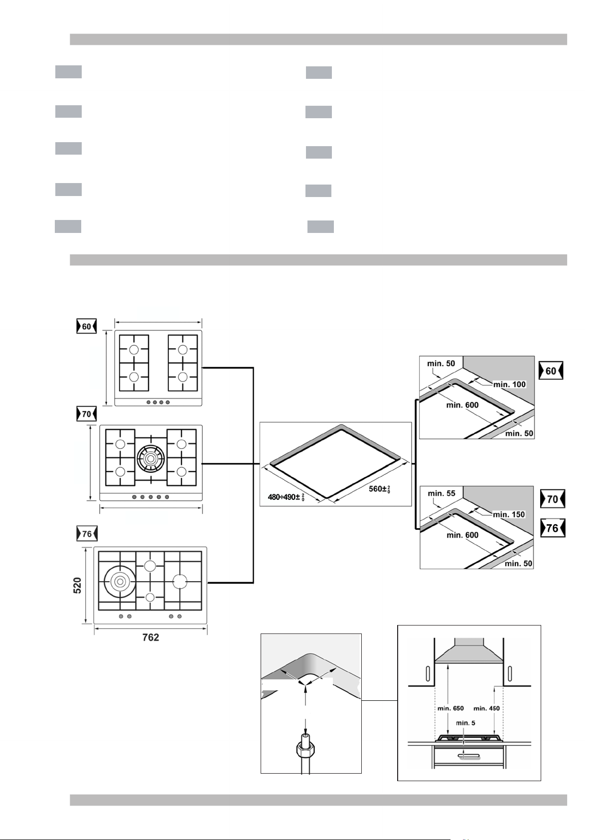
An oven must have forced ventilation to
install a hob above it.
Check the oven's dimensions in its
installation manual.
If an extractor fan is installed, you must
follow the installation manual's
instructions, always keeping a minimum
vertical distance of 650 mm to the hob.
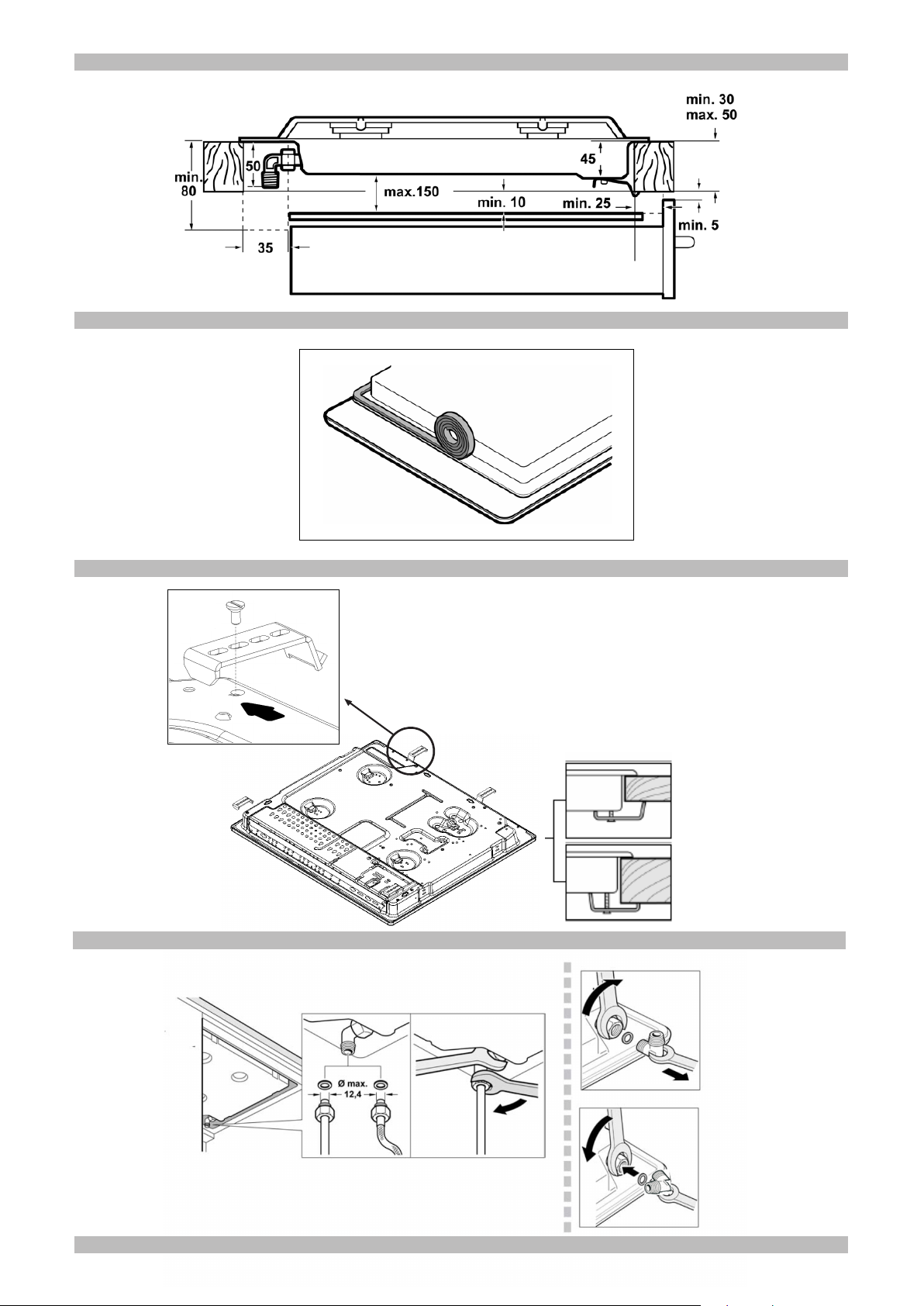
Preparation of kitchen unit
(fig. 1-2)
Make an appropriate size cut in the work
surface.
If the hob is electric or mixed (gas and
electricity) and there is no oven below,
place a non-flammable separator (e.g.
metal or plywood) 10 mm from the
bottom of the hob. This will prevent
access to the base of the hob.
If the hob is gas, it is recommendable to
place the separator at the same
distance.
On wood work surfaces, varnish the
cutting surfaces with a special glue. This
protects them from moisture.
Installation of appliance
Depending on the model, the adhesive
seal may be factory-fitted. If this is the
case, it should not be removed under
any circumstances, since the adhesive
seal prevents leaks. If the seal has not
been factory-fitted, apply it to the
underside of the hob. Fig. 3.
In order to fit the appliance into the
kitchen unit, tighten each of the clips as
indicated allowing them all turn freely.
Insert and centre the hob.
Press the sides of the hob until it is
supported around its entire perimeter.
Turn the clips and tighten them fully.
The clips position depends on the
thickness of the work surface. Fig. 4
Removal of hob
Turn off the appliance's electricity and
gas supply.
Unscrew the clips and proceed in the
reverse order to installation.
Gas connection (fig. 5)
The end of the inlet connection point of
the gas hob has a 1/2” thread that allows
for:
- fixed connection.
- connection using a flexible metal pipe.
It is necessary to insert the watertight
seal (034308) supplied between the
manifold outlet and the gas supply.
You must prevent the pipe from coming
into contact with moving parts of the
kitchen unit being inserted (for example,
a drawer) and prevent access to any
spaces which might become obstructed.
If you need to connect the gas supply
horizontally, our Technical Assistance
Service can supply you with an L-tube
(code 173018) and a seal (code
034308).
France: substitute the factory-fitted
L-tube for the accessory bag. Fig. 5a.
Please remember to insert the seal.
Warning! If any connection is handled,
check the seal.
Danger of leaks!
The manufacturer is not liable for any
connection leaking, after being handled.
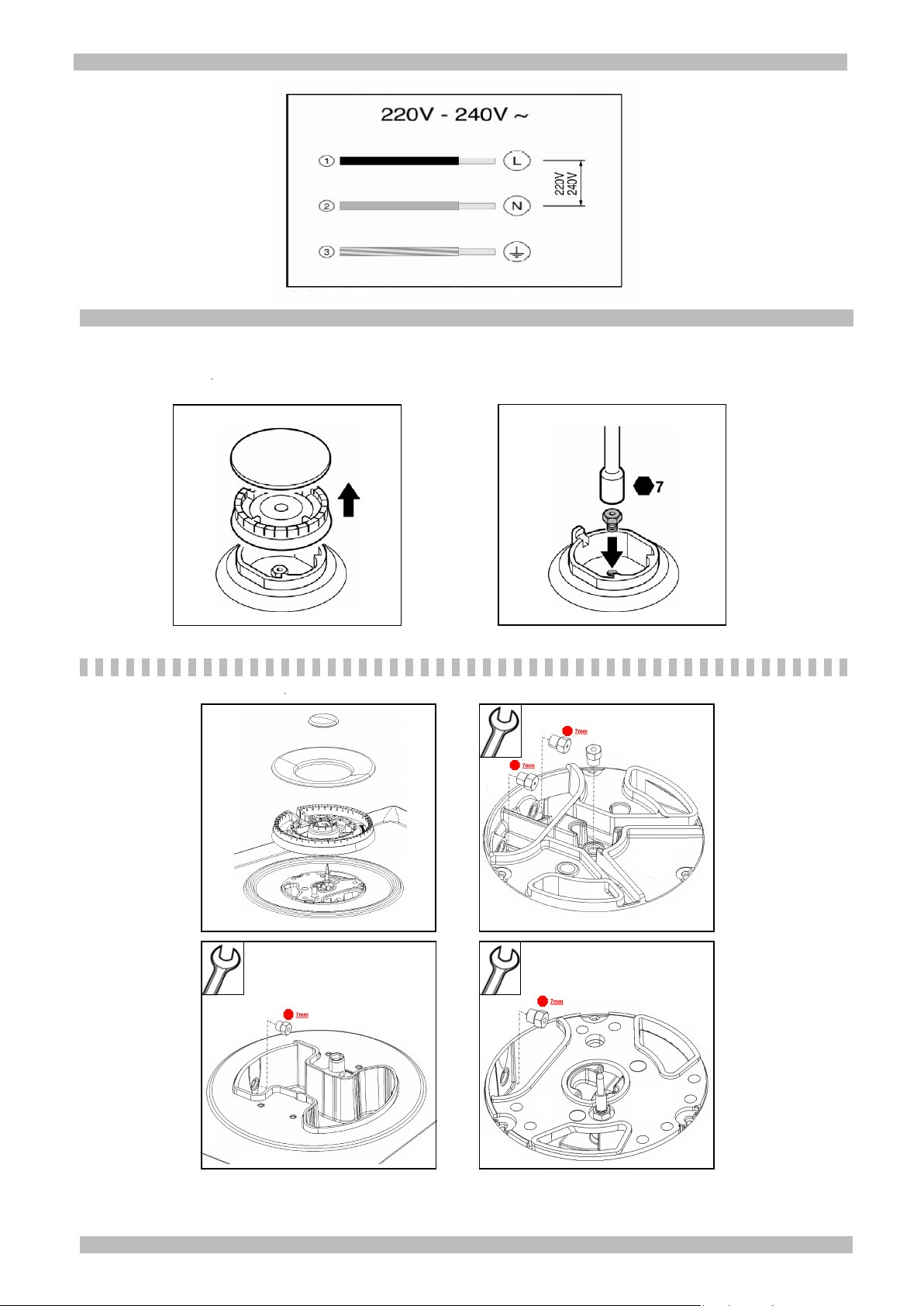
Electric connection (fig. 6)
Check that the voltage and power of the
appliance are compatible with the
electrical installation.
The hobs are supplied with a power
cable with or without a wall socket plug.
Provide an omnipolar cut-off switch with
a minimum contact separation of 3 mm
(except for plug connections, if the user
has access to it).
Appliances with plugs must only be
connected to sockets that have earth
wires correctly installed.
This appliance is type “Y”: the supply
cable can only be changed by the
Technical Assistance Service and not
the user. The cable type and minimum
cross-section must be respected.
Changing the gas type
If the country's regulations allow, this
appliance can be adapted to other types
of gas (see specifications plate). The
components required for this are in the
transformation kit supplied (depending
on the model) available from our
Technical Assistance Service. The
following steps should be taken:
A) Change the nozzles (fig. 7-7a):
- Remove the pan supports, burner
covers and diffusers.
- Change the nozzles using the spanner
provided by our Technical Assistance
Service with code 340847 (for double
and triple flame burners code 340808),
see table II, taking special care to
ensure that the nozzle does not fall
when it is removed from the burner or
when fitted.
Ensure that it is completely tightened in
order to guarantee the seal. Primary air
adjustment is not necessary with these
burners.
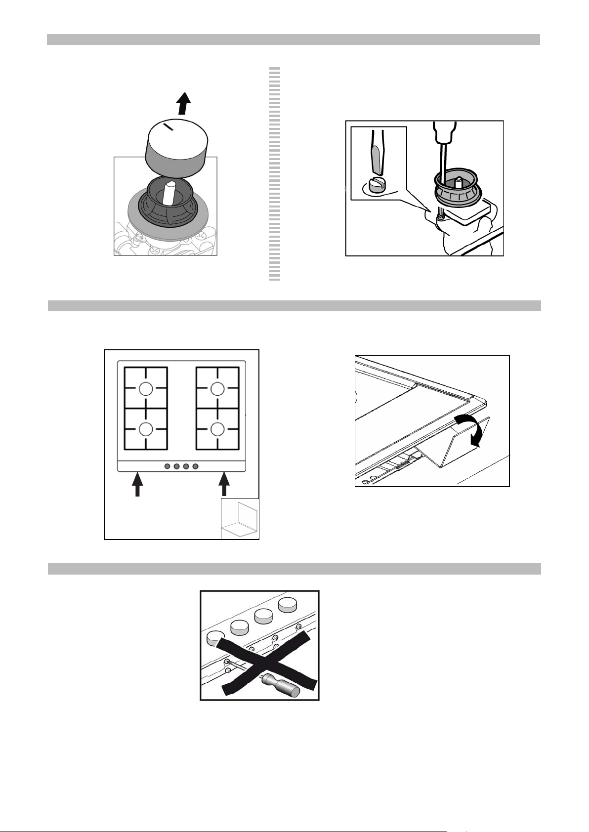
B) Adjust the taps
Set the control knobs to minimum.
Remove the control knobs from the taps.
Fig. 8. It has an outer seal. Simply press
on this seal with the tip of a screwdriver
to allow access to the tap adjusting
screw. Fig. 8a.
Never remove the seal.
Adjust the minimum ring setting by
turning the by-pass screw using a flat
head screwdriver.
Depending on the gas to which your
appliance is going to be adapted (see
table III), carry out the corresponding
action:
A: firmly tighten the by-pass screws.
B: loosen the by-pass screws until the
gas flow from the burners is correct:
when adjusting the control knob
between maximum and minimum, the
burner does not go out, nor is there a
flame backdraught created.
C: the by-pass screws need to be
changed by an authorised engineer.
D: do not touch the by-pass screws.
If the by-pass screw cannot be
accessed, disassemble the grease
splash tray, which is fixed to the rest of
the hob using a clip and screw mounting
system. The following steps must be
taken to remove the grease splash tray:
- Remove all the burner covers, pan
supports and control knobs.
- Loosen the screws on the burners.
Use the disassembly lever 483196
availablle from our Technical Assistance
Service. To release the front clips, apply
the lever to the area shown in figure 9.
To assemble the grease splash tray
again, proceed in the reverse order to
removal.
It is important that all the seals are
refitted to form an electrical seal.
These devices are essential for the
correct operation of the appliance as
they prevent liquids and dirt from
entering the appliance.
Refit the control knobs.
Never remove the tap spindle. In the
event of a malfunction, change the
whole tap.
Warning! After finishing, the sticker
indicating the new type of gas must

be placed close to the specifications
plate.
DE
de
Lesen Sie die Gebrauchsanweisung für
das Gerät, bevor Sie es installieren und
benutzen.
Die Abbildungen in dieser Anleitung
dienen der Veranschaulichung.
Der Hersteller ist jeglicher
Verantwortung enthoben, wenn die
Bestimmungen dieses Handbuchs
nicht eingehalten werden.
Sicherheitshinweise zu
diesem Gerät
Alle Installations-, Regelungs- und
Umstellungsarbeiten auf eine andere
Gasart müssen von einem
autorisierten Fachmann und unter
Beachtung der jeweils anwendbaren
Regelungen und gesetzlichen
Vorgaben sowie der Vorschriften der
örtlichen Strom- und Gasversorger
vorgenommen werden.
Für Umstellungsarbeiten auf eine
andere Gasart empfehlen wir, den
Kundendienst zu rufen.
Stellen Sie vor der Durchführung
jeglicher Arbeiten die Strom- und
Gaszufuhr ab.
Dieses Gerät wurde ausschließlich für
die Verwendung in Privathaushalten
und nicht für die gewerbliche Nutzung
entworfen. Dieses Gerät darf nicht auf
Jachten oder in Wohnwagen eingebaut
werden.
Überprüfen Sie vor der Installation des
Geräts, dass die örtlichen
Voraussetzungen (Gasart und -druck)
und die Geräteeinstellungen
miteinander kompatibel sind (siehe
Tabelle I). Die Bedingungen für die
Geräteeinstellung finden Sie auf dem
Etikett oder Typenschild.
Dieses Gerät darf nur an einem
ausreichend belüfteten Ort und nur in
Übereinstimmung mit den für die
Belüftung geltenden Bestimmungen und
Richtlinien eingebaut werden. Das
Gerät darf nicht an einen Schornstein
oder eine Abgasanlage angeschlossen
werden.
Das Netzkabel muss am Einbaumöbel
gut befestigt werden, damit es nicht mit
heißen Teilen des Backofens oder des
Kochfeldes in Berührung kommen kann.
Elektrische Geräte müssen immer
geerdet werden.
Hantieren Sie nie im Inneren des
Gerätes. Rufen Sie gegebenenfalls
unseren Kundendienst an.
Vor dem Einbau
Dieses Gerät entspricht Klasse 3 gemäß
EN 30-1-1 für Gasgeräte: Einbaugeräte.
Die neben dem Gerät befindlichen
Möbel müssen aus nicht brennbaren
Materialien sein. Die Schichtwerkstoffe
der Möbel sowie der sie
zusammenhaltende Leim müssen
hitzebeständig sein.
Dieses Gerät darf nicht über
Kühlschränken, Waschmaschinen,
Spülmaschinen oder ähnlichen Geräten
eingebaut werden.
Wenn Sie das Kochfeld über einem
Backofen installieren, muss dieser über
eine Zwangsbelüftung verfügen.
Überprüfen Sie die Abmessungen des
Backofens in Ihrem
Installationshandbuch.
Wenn eine Dunstabzugshaube
angebracht wird, muss dies gemäß der
Montageanleitung und immer unter
Berücksichtigung eines vertikalen
Mindestabstandes von 650 mm zum
Kochfeld geschehen.
Vorbereitung des
Küchenmöbels (Abb. 1-2)
Nehmen Sie in der Arbeitsfläche einen
Ausschnitt mit den benötigten
Abmessungen vor.
Wenn es sich bei dem Kochfeld um ein
elektrisches oder gemischtes Kochfeld
(Gas und elektrisch) handelt und sich
kein Ofen darunter befindet, bringen Sie
einen Zwischenboden aus nicht
brennbarem Material (z.B. Metall oder
Sperrholz) 10 mm unter dem Boden des
Kochfeldes an. So wird ein Zugang zum
unteren Teil des Kochfeldes verhindert.
Wenn es sich bei dem Kochfeld um ein
Gaskochfeld handelt, wird empfohlen,
den Zwischenboden im selben Abstand
zum Kochfeld anzubringen.
Bei Arbeitsflächen aus Holz firnissen Sie
die Schnittflächen mit Spezialleim, um
sie vor Feuchtigkeit zu schützen.
Einbau des Gerätes
Je nach Modell kann die Klebedichtung
bereits im Werk angebracht worden
sein. Die Klebedichtung dann
keinesfalls entfernen, sie verhindert
Durchsickern. Wenn die Dichtung nicht
werkseitig angebracht wurde, kleben
Sie sie an den unteren Rand des
Kochfeldes. Abb. 3.
Zur Befestigung des Geräts im
Einbaumöbel muss jede einzelne dieser
Klammern soweit ansgeschraubt
werden, dass sie sich frei drehen
können.
Fügen Sie das Kochfeld mittig ein.
Drücken Sie die Ränder solange nach
unten, bis der gesamte Rand aufliegt.
Drehen Sie die Klammern und ziehen
Sie diese fest an. Die Position der
Klammern ist abhängig von der Dicke
der Arbeitsfläche. Abb. 4.
Ausbau des Kochfeldes
Trennen Sie das Gerät von der Stromund Gasversorgung.
Schrauben Sie die Klammern auf und
folgen Sie den Einbauschritten in
umgekehrter Reihenfolge.
Gasanschluss (Abb. 5)
Am Ende des Eingangsrohrs zum
Gaskochfeld befindet sich ein 1/2”
Gewinde. Dieses Gewinde ermöglicht:
- einen Festanschluss.
- einen Anschluss mit einem
Metallschlauch.
Die Dichtung (034308) (mitgeliefert)
muss zwischen dem Auslass der
Sammelleitung und dem Gasanschluss
angebracht werden.
Es ist zu vermeiden, dass der Schlauch
in Kontakt zu den beweglichen Teilen
der Einbaueinheit gelangt (z. B. mit einer
Schublade) und durch Öffnungen
verlegt wird, die verschlossen werden
könnten.
Wenn ein horizontaler Gasanschluss
hergestellt werden soll, liefert Ihnen
unser Kundendienst einen Krümmer mit
der Teilenummer 173018 sowie eine
Dichtung mit der Teilenummer 034308.
Für Frankreich: Ersetzen Sie den
werkseitig montierten Krümmer mit
dem, der sich im Zubehörbeutel befindet
Abb. 5a.
Vergessen Sie nicht, dazwischen die
Dichtung anzubringen.
Achtung! Nach Arbeiten an einer
Anschlussstelle diese immer auf
Dichtheit prüfen.
Gasaustrittsgefahr!
Der Hersteller übernimmt für den
Gasaustritt an einer Anschlussstelle, an
der zuvor hantiert wurde, keine
Verantwortung.
Elektrischer Anschluss
(Abb. 6)
Prüfen Sie, ob Spannung und
Nennleistung des Geräts mit der
elektrischen Installation
übereinstimmen.
Die Kochfelder werden mit Netzkabel
mit oder ohne Stecker ausgeliefert.
Es muss ein allpoliger Trennschalter mit
mindestens 3 mm Kontaktabstand
angebracht werden (außer bei
Anschluss an eine frei zugängliche
Steckdose).
Mit Stecker ausgestattete Geräte dürfen
nur in vorschriftsmäßig angebrachte,
geerdete Steckdosen gesteckt werden.
Das Gerät gehört zum Typ "Y". Das
Zuleitungskabel darf nicht vom
Benutzer, sondern nur vom
Kundendienst ausgetauscht werden.
Sowohl Kabeltyp als auch minimaler
Querschnitt müssen berücksichtigt
werden.
Umstellung auf eine andere
Gasart
Wenn die einschlägigen Bestimmungen
des jeweiligen Landes dies erlauben,
kann dieses Gerät auf andere Gasarten
umgestellt werden (siehe Typenschild).
Die hierfür notwendigen Teile befinden
sich im mitgelieferten Umbaukit (je nach
Modell), das über den Kundendienst
bezogen werden kann. Es müssen
folgende Schritte befolgt werden:
A) Austausch der Düsen (Abb. 7-7a):
- Nehmen Sie die Roste, Deckel und
Brennerkörper ab.
- Tauschen Sie die Düsen (siehe
Tabelle II) mit dem über unseren
Kundendienst erhältlichen Schlüssel mit
der Teilenummer 340847 (für Doppelund Dreifachbrenner Teilenummer
340808) aus, wobei besonders darauf
zu achten ist, dass die Düse beim
Abdrehen oder Befestigen im Brenner
nicht abbricht.
Stellen Sie sicher, sie bis zum Anschlag
eingedreht zu haben, um eine gute
Abdichtung zu erreichen. Bei diesen
Brennern muss keine Einstellung der
Primärluft vorgenommen werden.
B) Einstellung der Gashähne
Drehen Sie die Bedienknebel auf die
minimale Position.
 Loading...