


US40a
N8120-011F
User's Guide
2nd Edition, March 2009
856-122300-111-01

Trademarks
Citrix, ICA (Independent Computing Architecture), and Program Neighborhood are registered trademarks of Citrix Systems,
Inc. in the USA and other countries. Citrix Presentation Server, Citrix XenApp, and SpeedScreen are trademarks of Citrix
Systems, Inc. in the USA and other countries.
Microsoft and Windows are registered trademarks of Microsoft Corporation.
All other product, brand, or trade names used in this publication are the trademarks or registered trademarks of their
respective trademark owners.
Windows Server 2003 stands for Microsoft® Windows Server® 2003, Standard Edition operating system, or Microsoft®
Windows Server® 2003, Enterprise Edition operating system.
Windows 2000 stands for Microsoft® Windows® 2000 Server operating system, Microsoft® Windows® 2000 Advanced
Server operating system, or Microsoft® Windows® 2000 Professional operating system.
Windows XP stands for Microsoft® Windows® XP Home Edition operating system, or Microsoft Windows XP Professional
operating system. Windows XP Embedded stands for Microsoft® Windows® XP Embedded.
Windows NT stands for Microsoft® Windows NT® Server network operating system version 3.51/4.0, or Microsoft®
Windows NT® Workstation operating system version 3.51/4.0.
Windows Me stands for Microsoft® Windows® Millennium Edition operating system.
Windows 98 stands for Microsoft® Windows®98 operating system.
Windows 95 stands for Microsoft® Windows®95 operating system.
Windows CE 5.0 stands for Microsoft® Windows® CE Version5.0.
Note: This equipment has been tested and found to comply with the limits for a Class B digital device, pursuant to Part 15 of
the FCC Rules. These limits are designed to provide the reasonable protection against harmful interference in a residential
installation. This equipment generates, uses and can radiate radio frequency energy and, if not installed and used in
accordance with the instructions, may cause harmful interference to radio communications.
However, there is no guarantee that interference will not occur in a particular installation. If this equipment does cause
harmful interference to radio or television reception, which can be determined by turning the equipment off and on, the user
is encouraged to try to correct the interference by one or more of the following measures.
Reorient or relocate the receiving antenna.
Increase the separation between the equipment and receiver.
Connect the equipment to an outlet on a circuit different from the one to which the receiver is connected.
Consult the dealer or an experienced radio/TV technician for help.
Use a shielded and properly grounded I/O cable to ensure compliance of this unit to the specified limits of the rules.
Notes:
(1) No part of this manual may be reproduced in any form without the prior written permission of NEC Corporation.
(2) The contents of this manual may be revised without prior notice.
(3) The contents of this manual shall not be copied or altered without the prior written permission of NEC Corporation.
(4) All efforts have been made to ensure the accuracy of all information in this manual. If you notice any part unclear,
incorrect, or omitted in this manual, contact your service representative.
(5) NEC assumes no liability arising from the use of this product, nor any liability for incidental or consequential damages
arising from the use of this manual regardless of Item (4).
(6) If you find any missing pages or pages out of order in this manual, please contact your service representative for a
replacement.
© NEC Corporation 2008, 2009
Keep this User's Guide at hand for quick reference at anytime necessary.
Be sure to read this section carefully.
NOTES ON SAFETY - Be sure to read this section -
The following includes information necessary for proper and safe operation of US40a. For details of
component names described in this section, See Chapter 1.
Safety Indications
Follow the instructions described in this User's Guide for your safety use of US40a.
Your US40a contains components with possible danger, hazards that may cause by ignoring
warnings, and this Guide describes preventive actions against such hazards. The components with
possible danger are described in this User's Guide.
In the User’s Guide, "WARNING" or "CAUTION" is used to indicate a degree of danger. These
terms are defined as follows:
WARNING
Indicates the presence of a hazard that may result in death or serious
personal injury.
CAUTION
Indicates the presence of a hazard that may cause minor personal injury,
including burns, or property damage.
Precautions against hazards are presented with the following symbols. The individual symbols are
defined as follows:
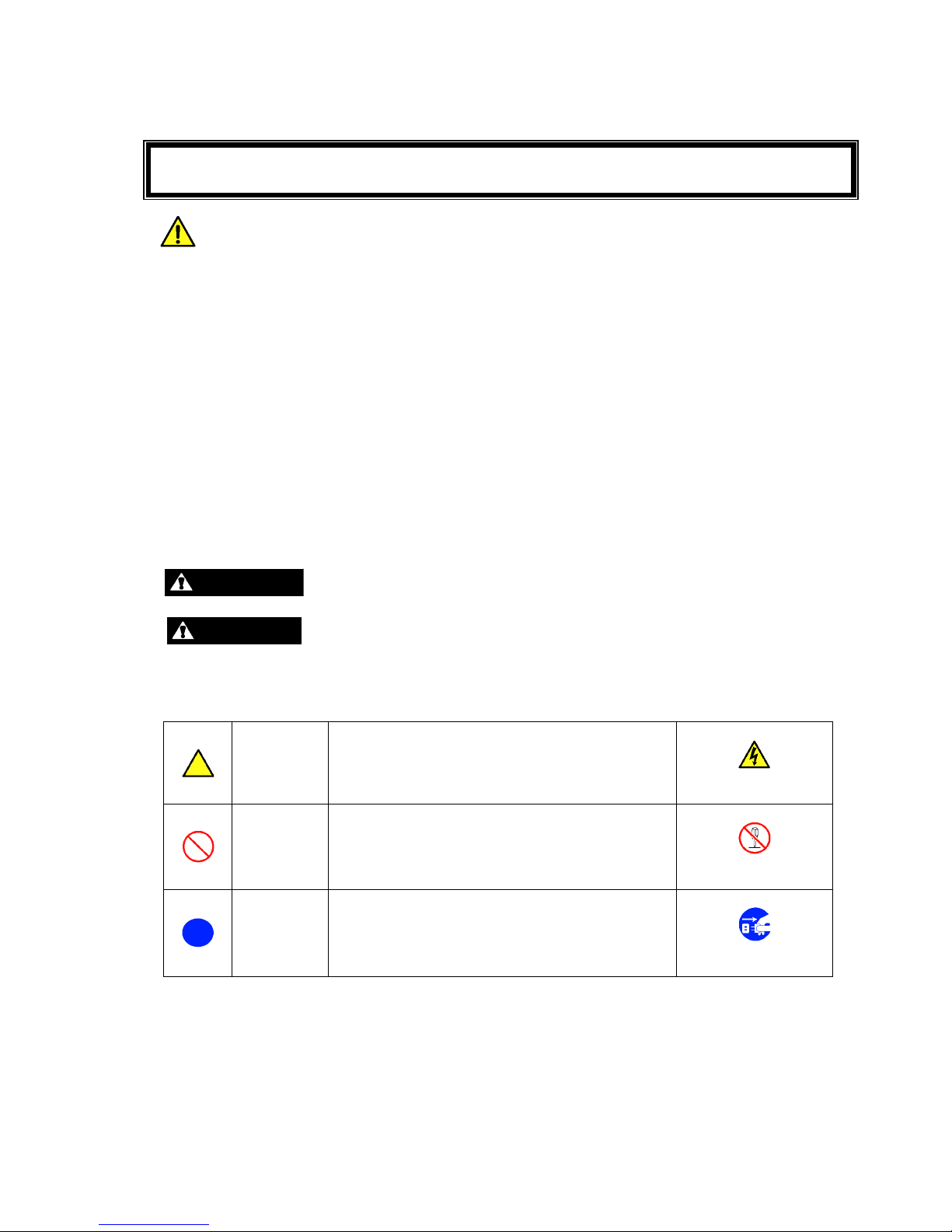
Attention
This symbol indicates the presence of a hazard.
An image in the symbol illustrates the hazard type.
(Example)
Precaution against
electric shock
Prohibited
Action
This symbol indicates prohibited actions. An
image in the symbol illustrates a particular
prohibited action.
(Example)
Prohibition of
disassembly
Compulsory
Action
This symbol indicates compulsory actions. An
image in the symbol illustrates a compulsory
action to avoid a particular hazard.
(Example)
Unplug the power
cord!
ii
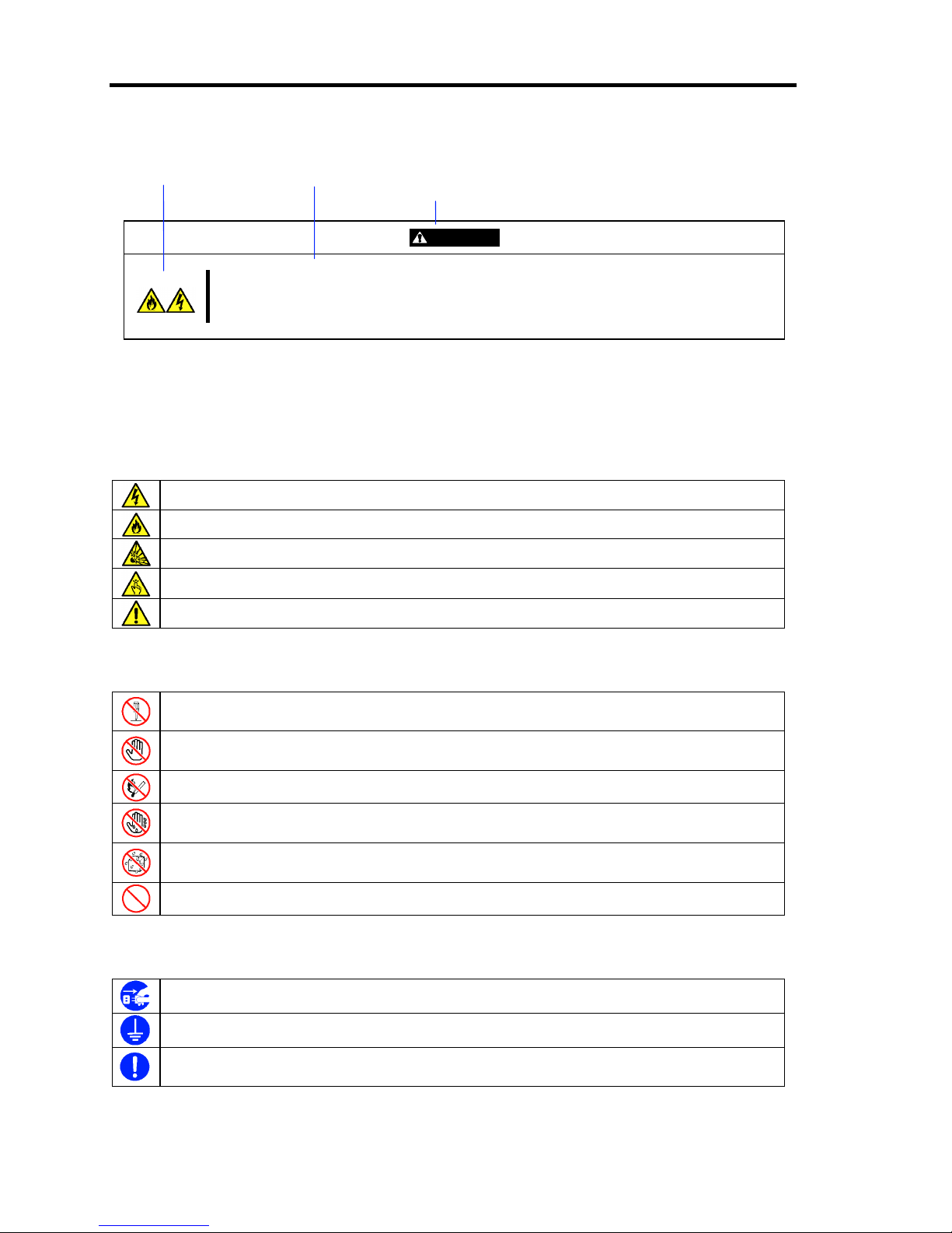
(Example)
Symbol to draw attention Description of a danger
Term indicating a degree of danger
WARNING
Plug in to a proper power source.
Use a proper wall outlet of the specified voltage. Use of an improper power source
may cause a fire or an electric leakage.
Symbols Used in This Guide and Warning Labels
Attentions
Indicates that improper use may cause an electric shock.
Indicates that improper use may cause fumes or fire.
Indicates that improper use may cause an explosion.
Indicates that improper use may cause personal injury.
Indicates a general notice or warning that cannot be specifically identified.
Prohibited Actions
Do not disassemble, repair, or modify US40a. Otherwise, an electric shock or fire may be
caused.
Do not touch the component specified. Otherwise, an electric shock or burn may be
caused.
Do not place US40a near a fire. Otherwise, a fire may be caused.
Do not touch US40a components with wet hand. Otherwise, an electric shock may be
caused.
Keep water or liquid away from US40a. Otherwise, an electric shock or a fire may be
caused.
Indicates a general prohibited action that cannot be specifically identified.
Compulsory Action
Unplug the power cord of US40a. Otherwise, an electric shock or fire may be caused.
Be sure to provide earthing. Otherwise, an electric shock or fire may be caused.
Indicates a compulsory action that cannot be specifically identified. Make sure to follow the
instruction.
iii
Safety Notes
This section provides notes on using your US40a safely. Read this section carefully to ensure proper
and safe use of US40a. For symbols, see "SAFETY INDICATIONS" provided earlier.
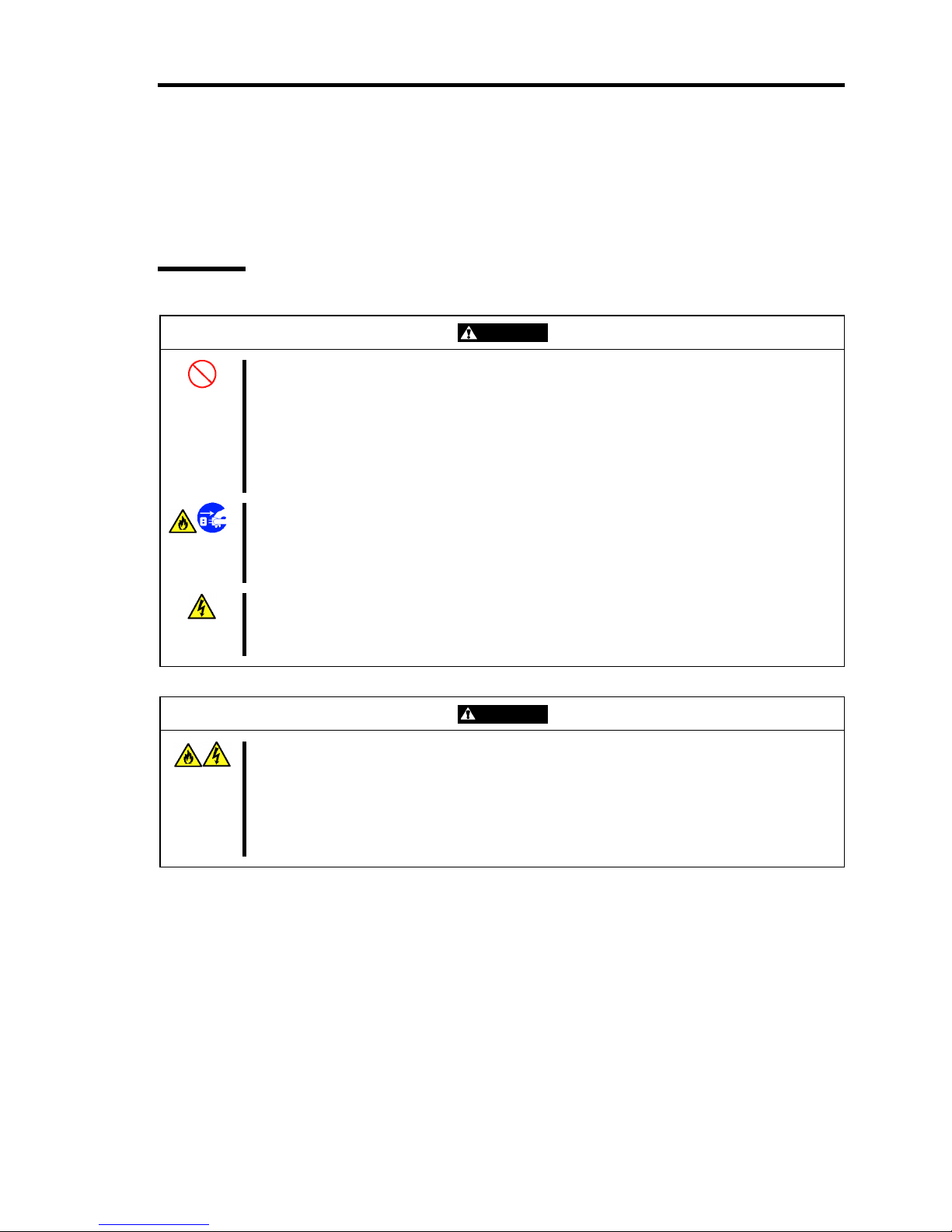
General
WARNING
Do not use US40a for services which may directly affect human lives and that
critically high reliability is required.
Your US40a is not intended to be used with or control facilities or devices concerning
human lives, including medical devices, nuclear facilities and devices, aeronautics and
space devices, transportation facilities and devices; and facilities and devices requiring
high reliability. NEC assumes no liability for any accident resulting in personal injury,
death, or property damage if US40a has been used in the above conditions.
Do not use US40a if any smoke, odor, or noise is present.
If smoke, odor, or noise is present, immediately turn off US40a and disconnect the
power plug from the outlet, then contact your service representative. Using US40a in
such conditions may cause a fire.
Keep needles or metal objects away from US40a.
Do not insert needles or metal objects into ventilation holes or the USB connector.
Doing so may cause an electric shock.
CAUTION
Keep water or foreign matter away from US40a.
Do not let any form of liquid (water etc.) or foreign matter (e.g., pins or paper clips)
enter US40a. Failure to follow this warning may cause an electric shock, a fire, or a
failure of US40a. When such things accidentally enter US40a, immediately turn off the
power and disconnect the power plug from the outlet. Do not disassemble US40a.
Contact your service representative.
iv
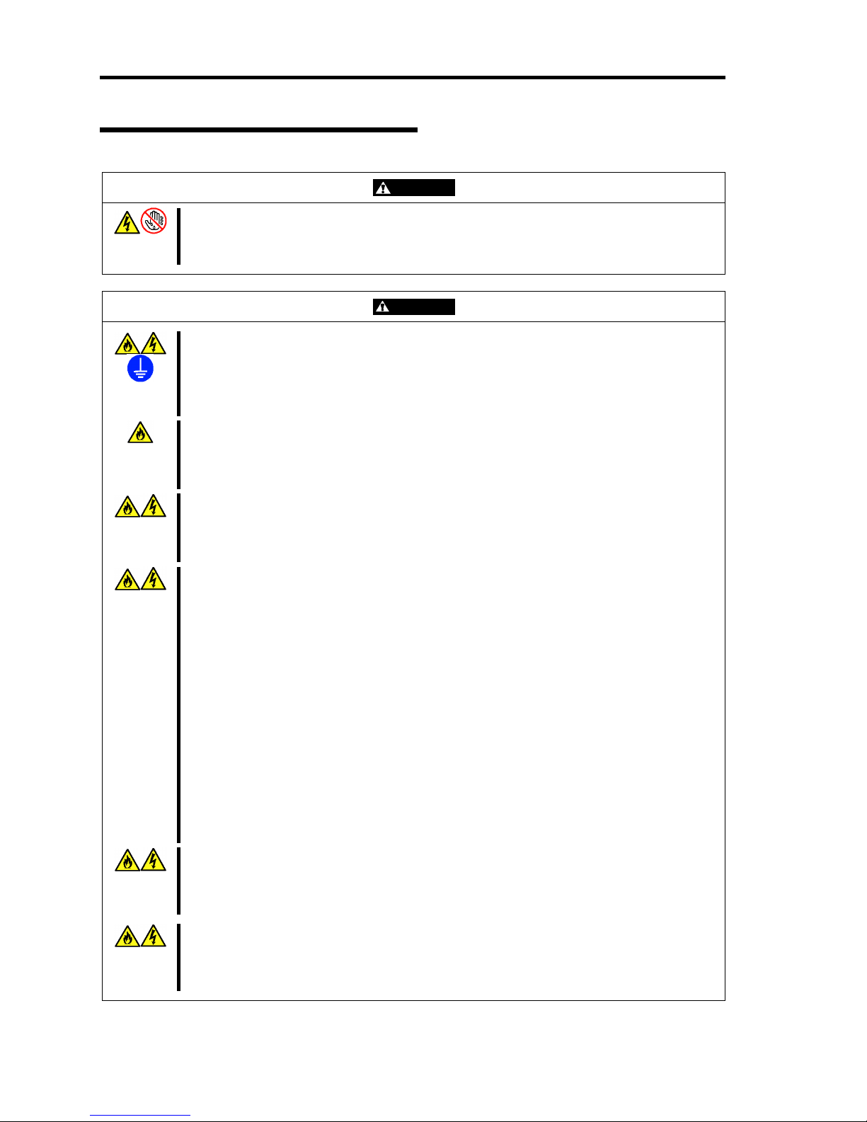
Power Supply and Power Cord Use
WARNING
Do not hold the power plug with a wet hand.
Do not disconnect/connect the plug while your hands are wet. Failure to follow this
warning may cause an electric shock.
CAUTION
Plug in to a proper power source.
Use a proper wall outlet of the specified voltage. Use of an improper power source may
cause a fire or an electric leakage.
Do not install US40a where you need an extension cord. Use of a cord that does not
meet the power specifications of your US40a may heat up the cord and cause a fire.
Do not connect exceeding number of power cords to a power outlet to prevent
excessive electrical load.
The electric current exceeding the rated flow overheats the outlet, which may cause a
fire.
Insert the power plug into the outlet as far as it goes.
Heat generation resulting from a halfway inserted power plug (imperfect contact) may
cause a fire. Heat will also be generated if water droplet is formed on dusty plug and
causes the short circuit. The heat may result in fire.
Use the authorized power cord only.
Use only the power cord that comes with your US40a. Use of an unauthorized power
cord may cause a fire when the electric current exceeds the rated flow.
Also, observe the following to prevent an electric shock or fire caused by a damaged
cord.
■ Do not stretch the power cord.
■ Do not bend the power cord.
■ Do not twist the power cord.
■ Do not step on the power cord.
■ Do not bundle the power cords.
■ Do not pinch the power cord.
■ Keep chemicals away from the power cord.
■ Do not place any object on the power cord.
■ Do not alter, modify, or repair the power cord.
■ Do not secure the power cord with staples or equivalents.
■ Do not use any damaged power cord. (Replace a damaged power cord with a new
one of the same specifications. Ask your service representative for replacement.)
Do not use the attached power cord for any other devices or usage.
The power cord that comes with your US40a is designed aiming to connect with this
US40a, and its safety has been tested. Do not use the attached power cord for any
other purpose. Doing so may cause a fire or an electric shock.
Do not pull the cord to disconnect the power cord.
Hold the connector of the power cord and pull it straight. Pulling the cord or applying
excess force to the connector may cause a damage to the cable, resulting in a fire or
an electric shock.
v
Installation, Relocation, Storage, and Connection
CAUTION
Do not install US40a in any place other than specified.
Do not install US40a in the following places or any place other than specified in this
Guide. Failure to follow this instruction may cause a fire.
■ a dusty place
■ a humid place such as near a boiler
■ a place exposed to direct sunlight
■ an unstable place
Do not use US40a in the place where corrosive gases exist.
Make sure not to locate or use US40a in the place where corrosive gases (sodium
chloride, sulfur dioxide, hydrogen sulfide, nitrogen dioxide, chlorine, ammonia, ozone,
etc.) exist.
Also, do not set it in the environment where the air (or dust) includes components
accelerating corrosion (ex. sulfur, etc.) or conductive metals. There is a risk of a fire
due to corrosion and shorts of an internal printed board. Ask your service
representative for a place appropriate to US40a if you have any questions about the
environment.
vi
Battery Unit
WARNING
Do not put a battery in fire.
Putting the battery in fire or heating the battery may cause an explosion.
Do not disassemble or alter the battery unit.
Do not disassemble or alter the battery unit. Doing so may cause an explosion or a
liquid leakage. The quality, performance, and/or safety of the disassembled or altered
battery unit will not be guaranteed.
Always charge battery by the specified method.
When charging battery, follow procedures described in User's Guide of US40a. Using
any other method may cause a heat generation, an ignition, and/or liquid leakage.
Do not give any shock on the battery unit.
Doing so may cause fumes, ignition, explosion and/or liquid leakage.
CAUTION
Keep the battery in the place away from children and babies.
The toxic substance contained in the battery is harmful if it is taken into the body by
mistake. Consult your doctor immediately if it is swallowed.
Do not use your hand to slide the battery release latch.
Use a ballpoint pen or the like to slide the battery release latch. Using your finger to
slide the battery release latch may cause a damage to your finger.
vii
During Operation
CAUTION
Avoid contact with US40a during thunderstorms.
Disconnect the power plug from the outlet when a thunderstorm is approaching. If it
starts thundering before you disconnect the power plug, do not touch any part of
US40a including the cables. Failure to follow this warning may cause a fire or an
electric shock.
Keep pet animals away from US40a.
Excreta and/or body hair of the pet animals may enter US40a and result in a fire or an
electric shock.
Do not block the ventilation opening.
The internal temperature rises, and it may cause the fumes and/or fire.
Remove the headphone from your ear before connection.
Do not connect the headphone to the line-out connector of US40a while you are putting
it on your ear. Doing so may cause a damage to your ear.
Before connection, make sure that the sound volume is not so large.
Do not use US40a on your knee for a long time.
The bottom of US40a becomes hot, and it may cause the low temperature burn. If the
heating element remains touching a certain part of the body for a long time, an
erythema or a bulla is generated on skin. It is called the low temperature burn. Special
care must be taken if you have sensitive skin.
Pay attention to ventilation from the ventilation opening.
The temperature of exhaust from the ventilation opening is higher than the room
temperature. Exposing yourself to exhaust from the ventilation opening may cause a
low temperature burn. Special care must be taken if you have sensitive skin.
Do not use US40a with its LCD panel being closed.
The internal temperature rises, and it may cause the heat generation and/or damage to
US40a.
viii
Wireless Features
WARNING
Keep US40a at least 30 cm away from the internal artificial cardiac pacemaker.
Pay attention to use US40a at the place at least 30 cm away from the internal artificial
cardiac pacemaker. The internal artificial cardiac pacemaker may be influenced by the
radio wave.
Turn off the power or wireless communication features of US40a in a crowded
place.
Turn off the power or wireless communication features of US40a in a place, e.g., a
crowded train, where you must be close to another person.
If the person adjacent to you uses the medical equipment such as an internal artificial
cardiac pacemaker or a hearing aid, such equipment may be influenced by your
computer.
Turn off the power or wireless communication features of US40a in a place
where use of US40a is prohibited.
Turn off the power or wireless communication features of US40a in a place where use
of US40a is prohibited (e.g., medical treatment facility).
If any medical equipment is being used near US40a, turn off the power or wireless
communication features of US40a even though the use of US40a is not prohibited. The
medical equipment may be influenced and cause an accident. For more information,
ask the relevant medical treatment facility.
Turn off the power or wireless communication features of US40a in the airplane.
The airline companies restrict the use of wireless and electronic equipment according
to the flight status of the airplane. This product is the pertinent equipment. Turn off the
power or wireless communication features of US40a in the airplane. The electronic
equipment may be influenced and cause an accident. For more information, ask the
relevant airline company.
Turn off the wireless communication features of US40a if US40a cause the radio
interference.
If your US40a causes the radio interference to any other equipment, immediately turn
off the power or wireless communication features of US40a. The equipment may be
influenced and cause an accident due to malfunction.
ix
Care and Internal Components Handling
WARNING
Do not disassemble, repair, or alter US40a.
Never attempt to disassemble, repair, or alter US40a on any occasion. Failure to follow
this instruction may cause an electric shock or fire as well as malfunctions of US40a.
Disconnect the power plug before accessing inside US40a.
Make sure to power off US40a and disconnect the power plug from a power outlet
before cleaning, attachment and detachment of the cables. Touching the inside of
US40a with its power cord connected to a power source may cause an electric shock
even if US40a is off-powered.
Disconnect the power plug from the outlet occasionally and clean the plug with a dry
cloth. Heat will be generated if water droplet is formed on a dusty plug, which may
cause a fire.
LCD (Liquid Crystal Display)
CAUTION
Do not scratch the surface of the LCD with a pointed object.
Doing so may cause a damage to the LCD.
Do not apply an excess power on surface of the LCD or outer frame.
Doing so may cause a damage to the LCD.
Avoid getting the liquid leaked from the LCD in your mouth or on your skin.
If the liquid leaked from the LCD accidentally gets in your mouth, immediately gargle
and consult with your doctor. If it accidentally gets on your skin or in your eye, rinse it
with water 15 minutes or longer and consult with your doctor.

x
For Proper Operation
Observe the following notes for successful operation of US40a. Use of US40a ignoring the notes
will cause malfunctions or failures of US40a.
When you have just turned off US40a, wait at least 10 seconds before turning it back on.
If US40a is connected to the UPS, set at least 10 seconds delay in the power-on schedule.
Turn off the power of US40a and unplug the power cord from the outlet before relocating
US40a.
Clean US40a on a regular basis. Regular cleaning proactively prevents various failures of
US40a.
Lightning may cause a momentary voltage drop. To prevent this problem, it is
recommended to use of an uninterruptible power supply unit.
It is recommended that US40a should be stored in a place where the room temperature is
able to be maintained. It is preferable to store US40a under the condition (temperature: –
20°C to 60°C, humidity: 20% -80%, without condensation).
Turn off the cellular phone or pager around US40a. Radio interference may cause
malfunctions of US40a.
Observe the following notes on using and connecting an interface cable.
– Do not use any damaged cable connector.
– Do not step on the cable.
– Do not place any object on the cable.
– Do not use US40a with loose cable connections.
– Do not use any damaged cable.
Do not leave US40a for a long time (six months or longer) with the battery unit being
mounted. The battery may be weakened or dead. Be sure to remove the battery unit if you
do not use US40a for a long time.
Do not use US40a for a long time with its power cord being disconnected from the power
outlet, if the battery unit is not fully charged. The battery unit may be weakened or dead.
Be sure to connect the power cord of US40a to the power outlet if you need to use US40a
for a long time.

xi
Features for Future Enhancement
Please note that currently we do not guarantee the following operation of below mentioned features.
These features are reference only for future enhancement.
Adding new user
Joining domain
Transmission of setting information through common.txt
Specifying "Auto Delivery of Remote Connections" in Startup Setting
Starting in safe mode
Regarding the Transportation of this System
This system and/or associated options and accessories may be using lithium metal batteries or
lithium ion batteries.
There may be restrictions regarding the air or sea transportation of such lithium batteries.
Please contact your reseller or service company prior to transporting this system and/or its options.

xii
Preface
Congratulations on the purchase of your US40a.
US40a is a Thin Client terminal to be connected with the virtual PC of NEC product.
Read this User's Guide thoroughly to fully understand handling of US40a and appreciate its
functions to the maximum extent.
About This Guide
This manual is a guide for proper setup and use of your US40a. This manual also covers useful
procedures for dealing with difficulties and problems that may arise during setup or operation of
your US40a.
Keep this manual for future use.
Text Conventions
The following conventions are used throughout this User's Guide. For safety symbols, see
"SAFETY INDICATIONS" provided earlier.
IMPORTANT:
Items that are mandatory or require attention when using US40a
NOTE:
Helpful and convenient piece of information

xiii
Organization of this Guide
This User's Guide has five chapters. Each chapter covers information as shown below.
IMPORTANT: Read "NOTES ON SAFETY" first.
Be sure to read "NOTES ON SAFETY" described at the top of this
User's Guide before this section. "NOTES ON SAFETY" include
important points on operating US40a safely and correctly.
Chapter 1 About US40a
tells you names and features of components, how to install, connect, power-on, and
shutdown your US40a.
Chapter 2 Using Features of US40a
tells you how to use [All Programs] menu and [Control Panel].
Chapter 3 Using Advanced Features
tells you how to use advanced features of US40a.
Chapter 4 Administrator Features
provides the administrator with all the information necessary to setup US40a.
Chapter 5 Operation and Maintenance
provides you with all the information necessary to maintain successful operation of US40a.
This chapter also includes helpful information for solving problems that might occur with
your system.

xiv
In the Package
The shipping carton contains various accessories as well as US40a itself. See "Getting Started!" to
make sure that you have everything and that individual components are not damaged. If you find
any component missing or damaged, contact your service representative.
Transfer to Third Party
Make sure to provide this guide and all the accessories along with US40a to a third party.
Disposal
Dispose of US40a, battery, and all the option devices according to all national laws and regulations.
Also, dispose of the power cord provided with US40a to avoid diversion to some other devices.

xv
Contents
NOTES ON SAFETY - Be sure to read this section - ....................................i
Safety Indications .............................................................................................................................i
Symbols Used in This Guide and Warning Labels ..........................................................................ii
Safety Notes....................................................................................................................................iii
General .......................................................................................................................................iii
Power Supply and Power Cord Use ...........................................................................................iv
Installation, Relocation, Storage, and Connection ......................................................................v
Battery Unit................................................................................................................................vi
During Operation ......................................................................................................................vii
Wireless Features .....................................................................................................................viii
Care and Internal Components Handling ...................................................................................ix
LCD (Liquid Crystal Display)....................................................................................................ix
For Proper Operation....................................................................................................................... x
Features for Future Enhancement...................................................................................................xi
Regarding the Transportation of this System..................................................................................xi
Preface ...........................................................................................................................................xii
About This Guide ..........................................................................................................................xii
Text Conventions.......................................................................................................................xii
Organization of this Guide .......................................................................................................xiii
In the Package...............................................................................................................................xiv
Transfer to Third Party .................................................................................................................xiv
Disposal ........................................................................................................................................xiv
Contents ................................................................................................................................xv
Chapter 1 About US40a.......................................................................................1
Names and Functions of Components .............................................................................................2
Front View (in the state where the LCD panel is opened)........................................................... 2
Left Side View............................................................................................................................. 3
Right Side View ..........................................................................................................................4
Rear View.................................................................................................................................... 5
Bottom View ............................................................................................................................... 6
Component Functions .................................................................................................................7
Keyboard (Function Keys)...................................................................................................... 7
Touch Pad ...............................................................................................................................7
Status LEDs ............................................................................................................................ 8
Wireless Antennas................................................................................................................... 9
USB2.0 Ports .......................................................................................................................... 9
Express Card Slot..................................................................................................................10
AC Power Port...................................................................................................................... 10
Use of Touch Pad ......................................................................................................................11
Clicking/Double-clicking/Drugging ..................................................................................... 11
Using Expansion Features of Touch Pad ..............................................................................11
Wireless LAN Features..................................................................................................................12
Notes on Use of Wireless LAN ................................................................................................. 12
Notes on Security in Use of Wireless LAN Devices .................................................................13
Security Features Available for US40a......................................................................................14

xvi
Preventing Sniffing (Intercept)..............................................................................................14
Preventing Unauthorized Accesses .......................................................................................14
Setting Security in Higher Level...........................................................................................15
Setting up Wireless LAN...........................................................................................................15
Available Wireless LAN Features .............................................................................................16
Wireless Connection of US40a with Peripheral Supporting Wireless LAN (Host Machine)16
Installation .....................................................................................................................................17
Installation .................................................................................................................................17
Battery............................................................................................................................................19
Battery Pack ..............................................................................................................................19
Notes on Use of Battery in US40a.............................................................................................20
Proper Use of Battery............................................................................................................20
Action to be taken when remaining battery level becomes low during battery driving ........21
Defining action to be taken when remaining battery level becomes low ..............................21
Battery Charge Procedure..........................................................................................................22
Battery Charge Procedure .....................................................................................................22
Checking Battery Charge Status with Battery Status LED....................................................22
Checking Remaining Battery Level...........................................................................................22
Battery Refreshing.....................................................................................................................23
Conducting Battery Refreshing.............................................................................................23
Adding Battery Pack..................................................................................................................24
Battery Pack Addition Procedure ..........................................................................................24
Replacing Battery Pack .............................................................................................................26
Replacement Interval ............................................................................................................26
Battery Pack Replacement Procedure ...................................................................................27
Connections ...................................................................................................................................29
Turning On Power of US40a..........................................................................................................31
Setting Up System BIOS ...............................................................................................................32
Overview ...................................................................................................................................32
Starting ......................................................................................................................................33
Description of Keys and Screens...............................................................................................34
Parameters and Their Description .............................................................................................35
Main ......................................................................................................................................35
Advanced ..............................................................................................................................37
Boot.......................................................................................................................................38
Security .................................................................................................................................39
Exit........................................................................................................................................40
Using US40a..................................................................................................................................42
Basic Configuration...................................................................................................................43
Extension 1................................................................................................................................44
Extension 2................................................................................................................................45
VPN...........................................................................................................................................46
Basic Operations of US40a........................................................................................................47
Setting Date and Time ...............................................................................................................49
Configuring Network.................................................................................................................50
Configuring Connection for Virtual PC.....................................................................................53
Connecting to Virtual PC...........................................................................................................54
Logoff from Virtual PC .............................................................................................................55
Shutdown of US40a...................................................................................................................55
Auto Connection to Virtual PC..................................................................................................56
Program Initiated at Startup ..................................................................................................56

xvii
Chapter 2 Using Features of US40a.................................................................57
All Programs ............................................................................................................................. 57
Control Panel............................................................................................................................. 57
Local Area Connection .............................................................................................................. 58
Wireless Network Connection................................................................................................... 59
Wireless Network Connection Setting Procedure.................................................................59
Remote Desktop Connection..................................................................................................... 60
Connection to Citrix Server....................................................................................................... 61
Terminal Connection Manager.................................................................................................. 62
Connect / Disconnect............................................................................................................63
Create RDP Connection Entry.............................................................................................. 65
Edit RDP Connection Entry.................................................................................................. 67
Create ICA Connection Entry ............................................................................................... 69
Edit ICA Connection Entry................................................................................................... 70
Integrated Control Panel .......................................................................................................71
Option ................................................................................................................................... 72
Startup Folder............................................................................................................................ 73
Startup Program Setting ............................................................................................................ 74
Network Utilities....................................................................................................................... 75
Version Information...................................................................................................................77
Update .......................................................................................................................................78
Update Settings..................................................................................................................... 81
Sounds and Audio Devices........................................................................................................83
Keyboard................................................................................................................................... 84
Mouse........................................................................................................................................85
Display ...................................................................................................................................... 86
Date and Time ...........................................................................................................................87
Power Options........................................................................................................................... 88
Desktop Background Setting..................................................................................................... 89
Certificate Import ...................................................................................................................... 90
Chapter 3 Using Advanced Features ...............................................................91
Using Dual Display in Connection of US40a to Virtual PC ..........................................................92
VPN Connection............................................................................................................................ 94
System Configuration................................................................................................................ 94
Structure................................................................................................................................ 95
Intranet:................................................................................................................................. 95
VPN Setting Procedure for US40a............................................................................................ 96
VPN Connection for US40a.................................................................................................... 102
Setting RDP Encryption Level ....................................................................................................103
Time Synchronization.................................................................................................................. 104
Software Update ..........................................................................................................................105
1. Software Update via Network......................................................................................... 105
2. Preparation...................................................................................................................... 106
3. Executing Software Update ............................................................................................ 111
4. Checking Software Version of US40a ............................................................................ 112
Chapter 4 Administrator Features.................................................................. 113
Changing Computer Name...................................................................................................... 114
Default User Accounts ............................................................................................................ 116

xviii
Startup Setting .........................................................................................................................118
USB Storage Device Setting....................................................................................................120
Write Filter Settings.................................................................................................................126
Features of Write Filter .......................................................................................................126
Write Filter Setting and Releasing Procedures....................................................................126
Adding Device Such As Printer...............................................................................................128
Using Additional Software ......................................................................................................129
Installing or Uninstalling Software .....................................................................................129
Installing VPCC Tools.............................................................................................................130
Using DPM..............................................................................................................................131
DPM Sample Scenario ........................................................................................................131
Updating Software by Using Application Installer..................................................................132
Updating Software from USB Storage................................................................................132
Setting Initialization ................................................................................................................132
Using Internet Explorer and Windows Media Player with User Account ...............................133
Internet Explorer .................................................................................................................133
Windows Media Player.......................................................................................................133
Disabling Change of Network Settings with User Account.....................................................134
Enhancing Write Filter Setting ................................................................................................135
Enhancing Write Filter Setting............................................................................................135
Returning Write Filter Settings to Factory Default .............................................................135
Auto Logon User Setting.........................................................................................................136
Chapter 5 Operation and Maintenance ......................................................... 137
Cleaning...................................................................................................................................137
Cleaning of US40a ..............................................................................................................137
Troubleshooting.......................................................................................................................138
Problem when Using Combination of Two or More Thin Clients ......................................138
Problems with Connections of RDP/ICA/Internet Time .....................................................138
Problems with Built-in USB SmartCard Reader.................................................................138
Problems with IC Card Manager.........................................................................................139
Problems with Update Feature............................................................................................139
Problems with Printer..........................................................................................................139
Relocation and Storage............................................................................................................140
Appendix A Wireless LAN Specification List ............................................... 141
IEEE802.11a .......................................................................................................................141
IEEE802.11b/g....................................................................................................................141
IEEE802.11n Draft2.0.........................................................................................................142
Appendix B LCD Display ................................................................................ 143
Appendix C Specification............................................................................... 144
Appendix D Re-installation CD ...................................................................... 145
Re-installation Procedure....................................................................................................145

Chapter 1
About US40a
This chapter tells you how to install, connect, and shutdown US40a.
2 About US40a
Names and Functions of Components
The names and functions of components in US40a are described below.
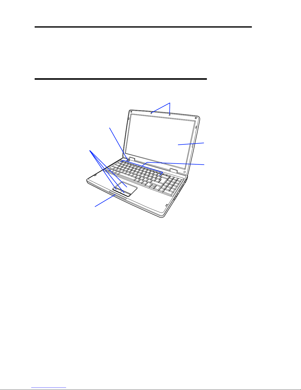
Front View (in the state where the LCD panel is opened)
1 LCD panel
2 Keyboard (function keys) (see page 7)
3 Touch pads (see page 7, 11)
4 Status LED (see page 8)
5 Power button (see page 31)
6 Radio antenna (see page 9)
1
2
3
4
5
6
About US40a 3
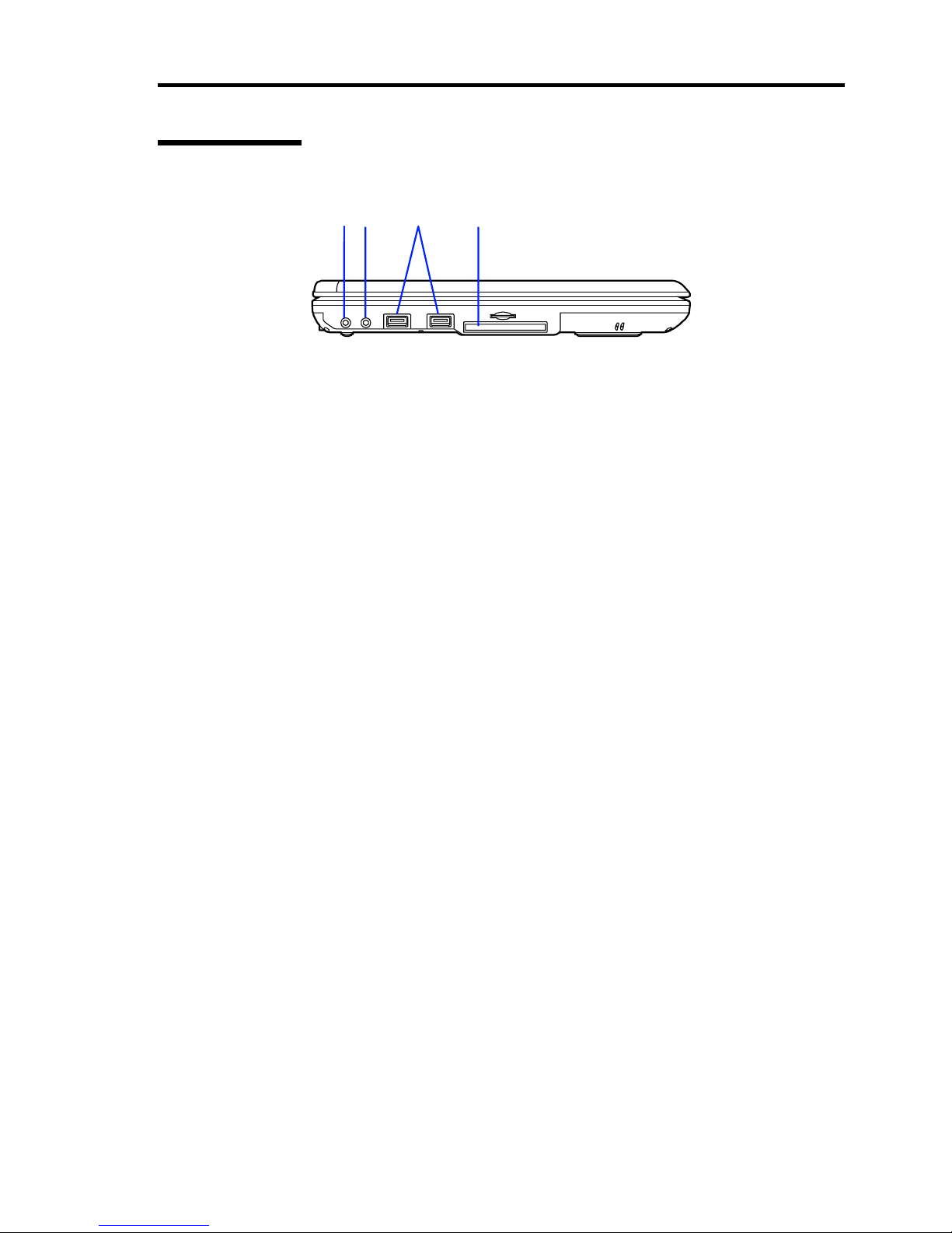
Left Side View
1 Microphone connector
Connect a microphone to this connector.
2 Lineout connector
Connect a headphone or an external speaker to this connector.
3 USB ports (2)
Connect a device having the USB interface to each of these ports.
4 Express Card slot
1
2
34
4 About US40a
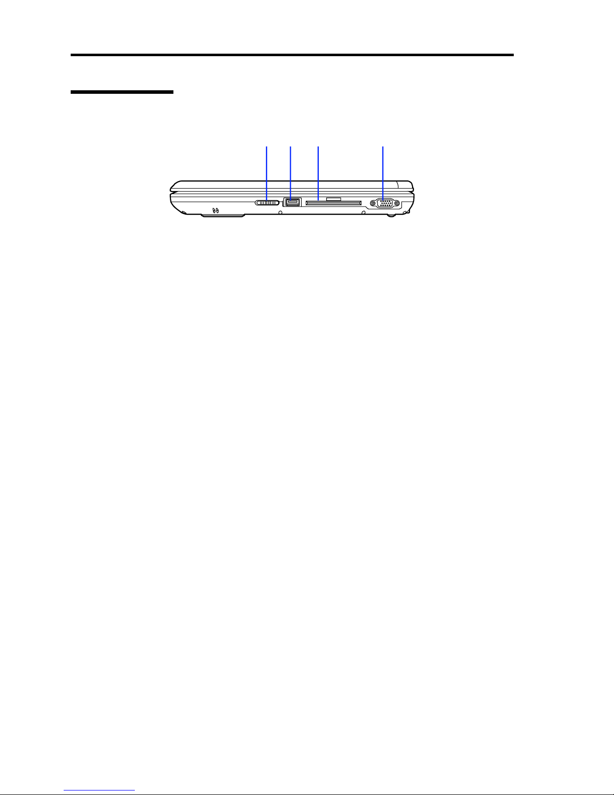
Right Side View
1 Wireless LAN button
Slide this button to the right to enable wireless LAN.
2 USB port
3 SmartCard reader
Security feature for user authentication
4 VGA port
Connect with an external monitor.
12 3 4
About US40a 5
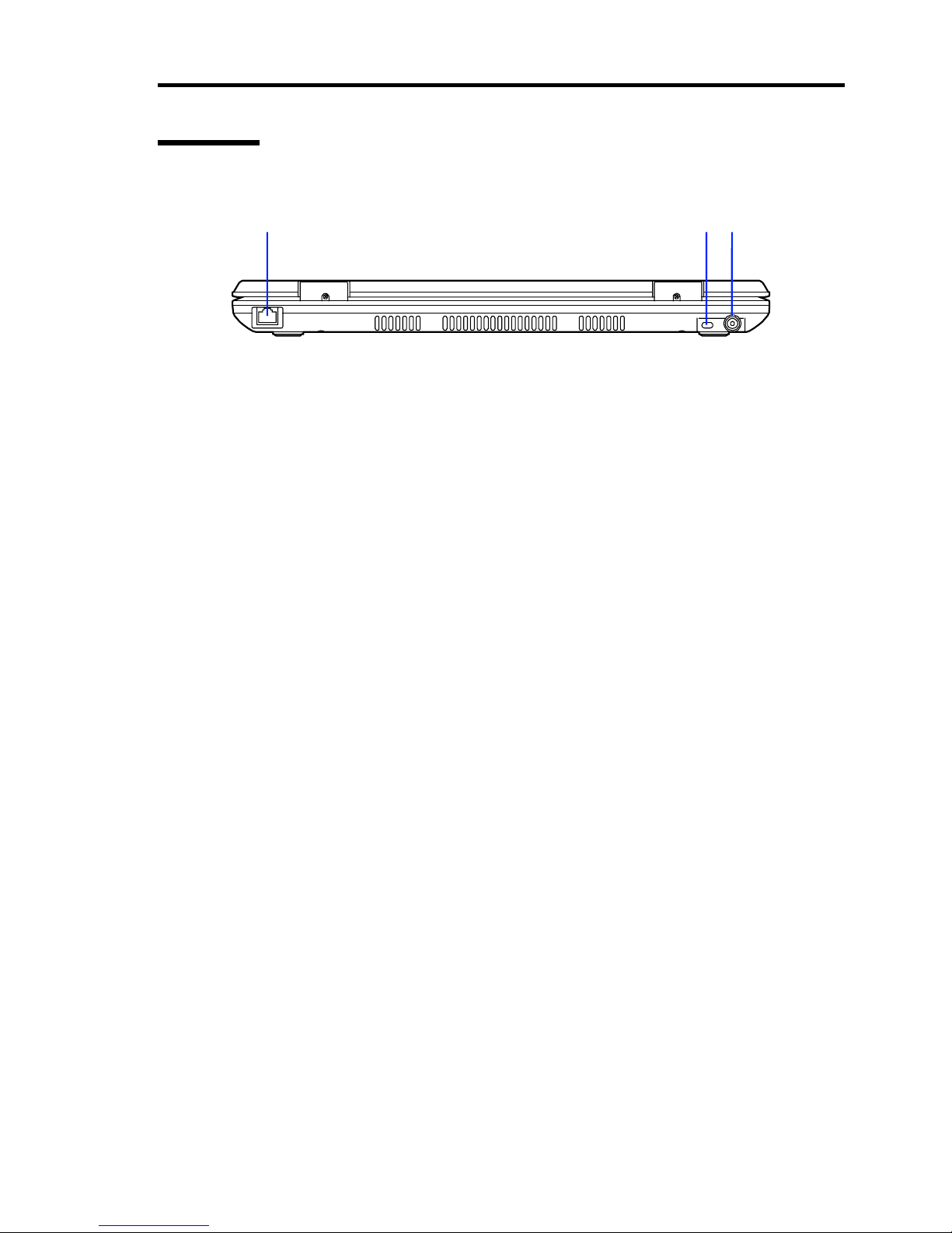
Rear View
1 LAN connector
Connect with a LAN network system.
Supports 10/100BASE-TX network subsystem.
2 Security lock slot
Install an antitheft device to this lock.
3 Power connector
Connect with the attached AC adapter.
123
6 About US40a
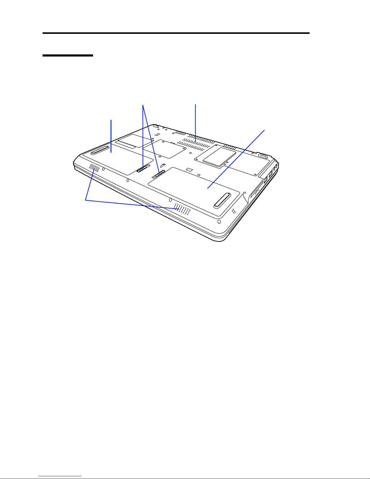
Bottom View
1 Speaker
2 Standard battery bay
3 Battery removal latch
4 Ventilating port
5 Additional battery bay
2
11
3
4
5

About US40a 7
Component Functions
Keyboard (Function Keys)
The keyboard includes twelve function keys F1 - F12. A function key pressed together with the Fn
key performs a specific function. Some of function keys (printed in blue) are previously
programmed to have two functions.
Fn+F1
Not defined
Fn+F6
Decreases the brightness of LCD.
Fn+F2
Not defined
Fn+F7
Increases the brightness of LCD.
Fn+F3
Activates or deactivates the touch pad.
Fn+F8
Lowers the volume.
Fn+F4
Activates or deactivates suspend mode.
Fn+F9
Turns up the volume.
Fn+F5 Changes the display from LCD to CRT
or vise versa.
Fn+F10
Mutes audio.
Touch Pad
The touch pad can be used as a normal mouse for PC. Just moving the tip of a finger on the touch
pad allows the position of the cursor to be adjusted.
Use the left or right selection button below the touch pad to select a menu item.
NOTE: Proper mouse setting allows scroll bars to be adjusted. If you
move a finger along the right edge of the touch pad, the focused
window can be scrolled in the vertical direction. In addition, if you
move a finger along the bottom edge of the touch pad, the focused
window can be scrolled in the horizontal direction.
8 About US40a
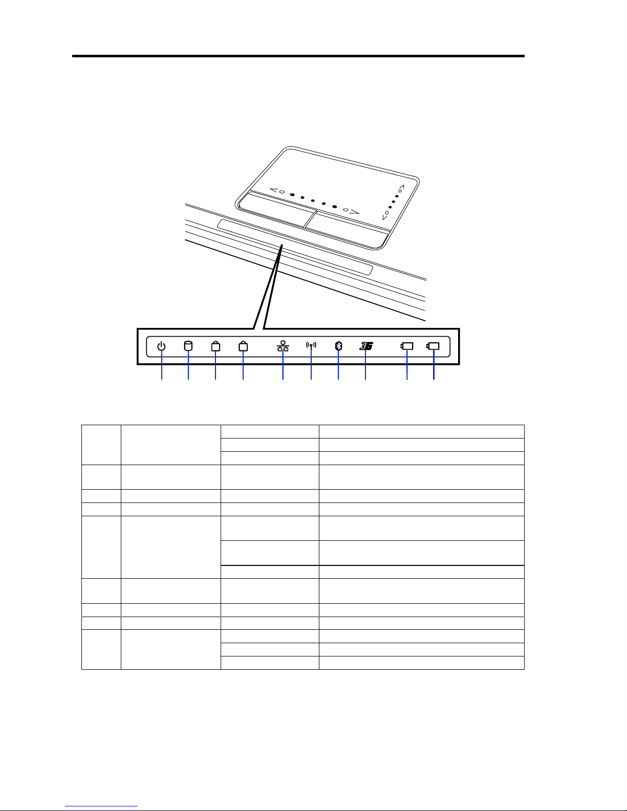
Status LEDs
See the table below for the indications and meanings of the status LEDs.
A 1
12
Off The power of US40a is OFF.
Lighting green The power of US40a is ON.
A Power status LED
Flashing green US40a is in the suspend mode.
B
Flash drive access
LED
Lighting green The system accessed to a flash drive.
C CAPS lock LED Lighting green CAPS lock is activated.
D NUM lock LED Lighting green NUM lock is activated.
Blinking green
slowly
The LAN feature is enabled.
Blinking green
rapidly
US40a is connected to LAN but data are
being transferred.
ELAN LED
Lighting green US40a is connected to LAN.
F Wireless LAN
status LED
Lighting green US40a is connected to wireless LAN.
G – – Not used
H – – Not used
Lighting green Battery is fully charged.
Lighting orange Battery is being charged.
I
and
J
Battery status LED
Blinking orange Battery is discharged almost fully.
A B C D E F G H I J

About US40a 9
Wireless Antennas
The wireless antennas send out signals from wireless devices installed in US40a and receive signals
sent from external devices.
These antennas cannot be viewed from the outside of US40a.
NOTE: Make the LCD panel of US40a remain opened. This can avoid
any obstacles against the antennas before wireless connection is
established.
IMPORTANT: The wireless devices installed in US40a are designed
so that their frequencies may not exceed the limit of the exposure to the
radio frequency recommended by the international guideline (ICNIRP).
The SAR (specific absorption rate), the rate at which the radio
frequency energy is absorbed into body issues, largely depends on the
distance between the origin of radio frequency (antenna) and a human
body.
The wireless devices meet the international guideline about the
exposure of radiated radio frequency only when the distance between
the antenna and a human body is at least 2 to 3 cm.
USB2.0 Ports
Three USB ports are located on US40a to allow peripherals conforming to the USB standard (e.g.
printers and DVD drives) to be connected to US40a.
IMPORTANT: The USB ports always supply 5VDC power to
external USB devices connected to the ports while the system power is
off. Accordingly, the USB devices can always be charged without the
system power. In order to prevent the battery power from being
discharged fully in the system power-off status, disconnect external
USB devices from the USB ports if they are not used.

10 About US40a
Express Card Slot
Only by inserting a memory card or a simply replaceable device into this Express Card slot, you can
add a hardware feature provided by a storage device, a wired or wireless communication card or a
safety device to US40a.
US40a can accept two types of Express Cards, or Express Card/34mm (width 34 mm) and Express
Card/54 mm (width 54 mm and L shape). The connectors on Express Cards of both types have the
same width (34 mm).
Standard cards are 75 mm in length (shorter than that of CardBus by 10.6 mm) and 5 mm in
thickness. Portions extended outward from the standard shape of the card due to an antenna or
socket may be thicker than 5 mm.
Inserting Express Card into Express Card Slot
Insert an Express Card into the Express Card slot in the following steps:
1. Align the Express Card to the connector so that the connector of the card faces the slot.
The arrow or the label shows the top side of the Express Card.
2. Slide the Express Card in the slot and press firmly until it is completely seated in its
connector.
3. The Express Card is automatically detected and a proper driver is installed.
The system may request you to use the driver supplied by the manufacturer. If this occurs,
insert the driver CD coming with the Express Card.
To inform you of success in the installation, US40a beeps twice.
Ejecting Express Card from Express Card Slot
Press the Express Card to eject it from the Express Card slot.
AC Power Port
Connect the AC adapter coming with US40a to this AC power port to supply AC power.
IMPORTANT: Be sure to use the AC adapter and the 2-pin power
cord coming with US40a. Using another adapter and/or power cord
may cause the system to be damaged even if they seem to be the same
as the attached ones.

About US40a 11
Use of Touch Pad
Clicking/Double-clicking/Drugging
Clicking
Put the pointer on an icon or a folder and press the left click button once.
If you press the right click button, you can select one of operations shown by the right button
clicking.
Double-clicking
Put the pointer on an icon or a folder and press the left click button twice quickly.
Drugging
To drug an icon or a folder, put the pointer on the icon or the folder and move the finger on the pad
with left click button pressed.
NOTES:
Tapping the pad with the tip of a finger leads the same operation as
clicking the mouse. Tapping the pad with the tip of a finger twice
quickly brings the same operation as double-clicking the mouse.
These actions are called "tap" and "double-tap", respectively.
Drugging also takes place if you tap the pad lightly with the pointer
put on an icon or folder, make a finger contact with the pad and
move the finger.
Using Expansion Features of Touch Pad
In addition to tapping and drugging on the pad only, you can use the useful expansion features as
follows:
Slipping a finger on the pad to scroll the screen (defining an area with scroll feature on the
pad).
Disabling the touch pad to avoid incorrect tapping and pointer moving during input on the
keyboard.
Turning on/off the touch pad temporarily.

12 About US40a
Wireless LAN Features
The wireless LAN features allow computers separated from one another to share data and programs
and transfer messages among them.
Notes on Use of Wireless LAN
The transmission speed and distance of wireless LAN vary depending on the used
wireless LAN devices, circumferential conditions including radio wave, obstacles and
installation environments.
The transmission speed of wireless LAN tends to be slower with longer communication
distance due to the nature of radio wave. For more comfortable usage of wireless LAN, it
is recommended to place wireless LAN devices within short distance.
The transmission speed and distance of wireless LAN (IEEE802.11b or IEEE802.11g)
supported devices may decrease while using a microwave oven near by. It is
recommended to use wireless LAN (IEEE802.11b or IEEE802.11g) supported devices
away from microwave oven.
When wireless LAN (IEEE802.11b or IEEE802.11g) supported devices and Bluetooth™
supported devices are used simultaneously, the transmission speed and distance of devices
may decrease. In such cases it is recommended to switch off either of the wireless LAN
(IEEE802.11b or IEEE802.11g) devices and the Bluetooth ™ supported devices or use by
keeping distance between them.
To connect US40a to a network, an optional wireless LAN access point is required.
Turn off the power of US40a or switch off the wireless LAN feature in an area where
medical authorities prohibit usage of this product. Moreover, even in the medical
establishment where usage of this product has been allowed, either turn off the power or
switch off the wireless LAN of this product when medical equipments are being used in
near by.
During network communication, do not enter US40a into the standby and suspend states.
Network communication shortens the period in which US40a can be driven by the battery
only. When communication for a long period is required, connect the AC adapter to
US40a to supply power through an AC outlet.
In standby or suspend mode the network feature is disabled temporarily. Therefore put
US40a into standby or suspend modes after completion of communication operations like
file copy etc. Moreover, some application software lost data while US40a recovers from
standby or suspend mode. While using applications which uses network, verify the same
with the system administrator and use the standby or suspend mode appropriately.

About US40a 13
Notes on Security in Use of Wireless LAN Devices
The wireless LAN can transfer data between a PC and a wireless access point through radio waves
instead of using LAN cables. Accordingly, the wireless LAN is advantageous to enable free LAN
connection within the area where radio waves can reach.
On the other hand, the wireless LAN may cause the following problems to occur without proper
security because radio waves can penetrate obstacles (including walls) to reach any places within a
certain range.
Communication data is sniffed.
Malicious third parties may intentionally intercept radio waves to sniff communication
data as follow:
– Personal information including user IDs, passwords and credit card numbers and
– E-mails.
Network is invaded illegally.
Malicious third parties may access to personal or corporate networks without permission
to:
– get out personal or confidential information (information leakage),
– spoof as a specific person to distribute wrong information (spoofing),
– intercept communication data, rewrite the data and send out the rewritten data
(alteration) and
– distribute computer virus to crack data and systems (cracking).
Wireless LAN cards and access points essentially have security schemes to cope with these
problems. Therefore, proper settings on security in wireless LAN devices can reduce the possibility
at which these problems occur.
It is recommended to be familiar with the problems in use of wireless LAN devices without security
and provide proper security settings in your judgment and responsibility.
If you cannot deal with security settings by yourself, contact your service representative.
NEC does not assume any responsibility for any losses caused by problems occurred due to no
security measures or unavoidable circumstances concerning wireless LAN specification.

14 About US40a
Security Features Available for US40a
NOTES:
To provide the following security settings for US40a, the access
point to be used must support such settings.
These settings are only means to reduce security risks as much as
possible but do not secure the safety of US40a completely.
Preventing Sniffing (Intercept)
The wireless LAN of US40a supports the WEP (Wired Equivalent Privacy) feature. Defining an
encryption key by using the WEP feature, you can encrypt wireless LAN communication data
among communication devices using the specific encryption key. This can prevent the
communication data from being sniffed and the communication devices from being connected from
unrelated PCs and devices. The WEP feature is divided into three types, or 64-bit, 128-bit and 152bit WEPs. The wireless LAN of US40a supports all the types of WEPs.
However, third parties may get the encryption key being set or decipher it with some encryption
decipher technology. Thus, it is recommended to modify the encryption key periodically.
NOTE: To use the WEP feature, remote communication devices must
also support the WEP feature.
Preventing Unauthorized Accesses
Setting a specific SSID (network name) to each of the access point and communication
devices, you can prevent any communication device without the same SSID from
connecting to US40a. However, the SSID may be known by third parties using devices
which can detect SSIDs automatically. To avoid this, the SSID must be hidden at the
access point so that the SSID may not be known.
If you register the MAC addresses (unique numbers assigned to network cards) of the
connected PC and other devices in the access point, any devices other than those
registered are disabled to connect to the access point (MAC address filtering).

About US40a 15
Setting Security in Higher Level
US40a uses the WPA (Wi-Fi Protected Access) feature proposed by the Wi-Fi Alliance.
Using the user authentication based on the IEEE802.1X/EAP (Extensible Authentication Protocol)
standard and TKIP (Temporal Key Integrity Protocol) or AES (Advanced Encryption Standard),
each of which is an encryption method making decryption difficult further more than the
conventional WEP feature, allow security setting at a higher level to be provided.
NOTE: To use encryption based on WPA, remote devices to be
connected to US40a must support the same security feature.
Setting up Wireless LAN
For how to set up the wireless LAN of US40a, see "Wireless Network Connection" described in this
User’s Guide.

16 About US40a
Available Wireless LAN Features
The wireless LAN features available in US40a are described below.
Wireless Connection of US40a with Peripheral Supporting Wireless LAN
(Host Machine)
Using US40a and an optional peripheral (host machine) supporting wireless LAN allows LAN to be
used without cable connections. For example, US40a can be connected to Internet through a router
or terminal adapter supporting wireless LAN.
NOTES:
US40a can provide wireless LAN connection or communication
with devices supporting 5GHz wireless LAN (IEE802.11a) in use of
the 5GHz band or devices supporting 2.4GHz wireless LAN
(IEEE802.11b or IEEE802.11g) in use of the 2.4GHz band. US40a
cannot provide wireless LAN connection or communication with
devices for other than 5GHz wireless LAN (IEE802.11a) and those
for other than 2.4GHz wireless LAN (IEEE802.11b or
IEEE802.11g).
US40a does not support ad-hoc connection in the IEEE802.11g
mode.

About US40a 17
Installation
This section describes the installation of US40a.
Installation
Select a site suitable for installing US40a.
CAUTION
Observe the following instructions to use US40a safely. Failure to follow these
instructions may cause a fire, personal injury, or property damage. See pages iv to
xi for details.
■ Do not install US40a in any place other than specified.
■ Do not use US40a on your knee for a long time.
■ Do not use US40a with your hands being put on keyboard or palm rest portion
for a long time.
Install US40a on the rigid,
flat place
Clean and tidy room
Environmental requirements:
<Operating>
Temperature: 10 to 35ºC*
Humidity: 20 to 80%
<Halting>
Temperature: –20 to 60ºC*
Humidity: 20 to 80%
Grounded parallel bi-polar
power outlet
Close enough to
connect the power cord
* It is recommended that US40a
should be used in a room where
temperature is in the range between
15 to 25ºC.

18 About US40a
Do not place US40a in the following places. Placing US40a in such places may cause malfunctions
of US40a.
Places with drastic changes in temperature (e.g., near a heater, air conditioner, or
refrigerator)
Places with strong vibration
Places where corrosive gases exist (in environment where sulfur vapor may be dispersed
in the air). Places where chemicals are nearby, or chemicals may be sprayed accidentally.
On a non-antistatic carpet
Places with possibilities of falling objects
Places where the power cord or interface cable may be stepped on or stumbled
Places near a device generating intense magnetic field (such as a TV, radio,
broadcast/communication antenna, power transmission wire, and electromagnetic crane)
(If unavoidable, contact your service representative to request proper shield construction.)
Places where a power outlet that shares the ground line with another (especially the one to
which a device with large power consumption is connected) must be used for US40a
Places near equipment that generates power noise (e.g., contact spark at power-on/power-
off of commercial power supply through a relay). (To install US40a near equipment that
generates power noise, ask your service representative for separating the power wiring or
installing a noise filter.)

About US40a 19
Battery
US40a can be operated only by the attached or optional battery pack without use of the AC adapter.
Battery Pack
The battery pack available for US40a uses lithium-ion battery.
Lithium-ion batteries are valuable and recyclable resources.
Notes on recycling of lithium-ion battery
Do not make batteries short-circuited. To insulate the battery terminal, stick the tape on
the terminals or put the battery in the plastic bag. Failure to follow this may cause fire or
electric shock.
Do not peel off exterior covers (such as coating and tubes) from batteries.
Do not disassemble batteries.

20 About US40a
Notes on Use of Battery in US40a
NOTES:
When the battery is charged sufficiently, do not install or remove the
battery pack from US40a if not required particularly. Failure to
follow this may cause the battery pack to be defected.
Charge the battery as full as possible when charged. If you repeat a
small amount of charging/discharging many times in low remaining
battery status, some error may occur in the remaining battery level.
Proper Use of Battery
To keep high display precision of the remaining battery level, refresh the battery
periodically.
When US40a is not used for a long period, remove the battery pack with the remaining
battery level of about 50% and save it in a cool place. This can lengthen the battery life.
When US40a is operated for a long time only by the battery, use the power saving feature
of US40a.
The battery discharges naturally. It is recommended to charge the battery once for two to
three months even if US40a is not used for a long period.

About US40a 21
Action to be taken when remaining battery level becomes low during battery
driving
When the remaining battery level becomes low, the Battery Status LED lights or blinks orange. If
this occurs, take either of the following actions depending on the situation:
When the AC power can be supplied to US40a through AC outlet:
Connect the AC adapter to US40a to supply power though the AC outlet. As soon as the
power is supplied, the Battery Status LED goes on and battery charging is started. US40a
can be operated while the battery is charged.
When AC outlets are not installed:
Terminate applications being used and turn off the power of US40a.
If the power of US40a is not turned off still without power supply through an AC outlet, US40a is
entered into the state set by [Power Options] in the [Control Panel].
NOTE: To open the power option, click [Start] - [Control Panel] -
[Power Options].
Defining action to be taken when remaining battery level becomes low
You can define the action taken to operate US40a or enter it into proper status when the remaining
battery level becomes low or the battery is fully discharged.
Define the action on the [Alarms] tab displayed by clicking [Start] - [Control Panel] - [Power
Options].

22 About US40a
Battery Charge Procedure
NOTES:
Do not remove the battery pack from US40a while the battery is
being charged. Failure to follow this may cause short-circuit and/or
poor contact.
The battery just purchased or left for a long period may not be
operated at all, be operated only for a short period or show the
remaining battery level incorrectly. Any battery in such status
should be charged fully before it can be used.
Battery Charge Procedure
If you connect the AC adapter to US40a with the battery pack installed and to an AC outlet, then
battery charge is automatically started.
The battery is charged while the power of US40a is ON.
NOTE: The chargeable battery level varies depending on the ambient
temperature. Battery charging may be interrupted at a higher
temperature. It is recommended to charge the battery within the ambient
temperature range between 18ºC and 28ºC.
Checking Battery Charge Status with Battery Status LED
You can check the battery charge status with the Battery Status LED.
Checking Remaining Battery Level
You can check the remaining battery level in the following steps:
1. Click [Start] - [Control Panel] - [Power Options].
The [Power Options Properties] dialog box appears.
2. Click the [Power Meter] tab.

About US40a 23
Battery Refreshing
Battery refreshing is required to recover the battery performance having decreased temporarily.
Conduct the battery refreshing in any of the following situations:
The operation time of US40a driven by the battery becomes shorter.
Repeating charge of a battery not discharged fully may cause its operation time to be
shorter due to decrease in the battery chargeable level. This is called "battery memory
effect".
The battery performance decreases temporarily just after you purchase US40a or because
the battery has not been used for a long period.
Some error occurs in the remaining battery indication.
Conducting Battery Refreshing
Conduct battery refreshing in the following steps:
IMPORTANT: Neither pull out the AC cable nor turn off the power
during battery refreshing. Failure to follow this may cause the battery to
operate incorrectly.
1. Turn on the power of US40a and press F2 to display the SETUP screen.
2. Select [Advanced] → [All Battery Calibration].
3. Select [OK].
4. After the following message appears, press Y.
Please make sure that AC adapter & Battery are present.
Do you wish to do battery auto-learning? (y/n)
The battery refreshing is started.
5. After the following message appears, press the power button to turn off the power for
terminating the battery refreshing.
Battery Auto-Learning completed. Press Power Button to Shutdown.

24 About US40a
Adding Battery Pack
WARNING
Do not put a battery in fire.
Putting the battery in fire or heating the battery may cause an explosion.
Do not disassemble or alter the battery unit.
Do not disassemble or alter the battery unit. Doing so may cause an explosion or a
liquid leakage. The quality, performance, and/or safety of the disassembled or altered
battery unit will not be guaranteed.
Always charge battery by the specified method.
When charging battery, follow procedures described in User's Guide of US40a. Using
any other method may cause a heat generation, an ignition, and/or liquid leakage.
Do not give any shock on the battery unit.
Doing so may cause fumes, ignition, explosion and/or liquid leakage.
CAUTION
Keep the battery in the place away from children and babies.
The toxic substance contained in the battery is harmful if it is taken into the body by
mistake. Consult your doctor immediately if it is swallowed.
Do not use your hand to slide the battery release latch.
Use a ballpoint pen or the like to slide the battery release latch. Using your finger to
slide the battery release latch may cause a damage to your finger.
Battery Pack Addition Procedure
NOTES:
Do not make your body contact with the terminals on the battery
slot. Failure to follow this may cause poor contact to occur.
Use a ballpoint pen or so to slide the battery removal latch. If the
battery removal latch is slid with a finger, it may be injured.

About US40a 25
1. A dummy battery is installed in the additional battery bay at the front right side of the
bottom of US40a. Slide the battery release latch to the depth by using a ballpoint pen o the
like to release the lock. Then remove the dummy battery.
2. Align the right side of the battery pack with the additional battery bay and press the left
side of the battery pack to install it.
When a click occurs, the battery pack is locked. Note the orientation of the battery pack in
its installation.
Now the new battery pack is installed completely.
Battery release latch
Dummy battery

26 About US40a
Replacing Battery Pack
WARNING
Do not put a battery in fire.
Putting the battery in fire or heating the battery may cause an explosion.
Do not disassemble or alter the battery unit.
Do not disassemble or alter the battery unit. Doing so may cause an explosion or a
liquid leakage. The quality, performance, and/or safety of the disassembled or altered
battery unit will not be guaranteed.
Always charge battery by the specified method.
When charging battery, follow procedures described in User's Guide of US40a. Using
any other method may cause a heat generation, an ignition, and/or liquid leakage.
Do not give any shock on the battery unit.
Doing so may cause fumes, ignition, explosion and/or liquid leakage.
CAUTION
Keep the battery in the place away from children and babies.
The toxic substance contained in the battery is harmful if it is taken into the body by
mistake. Consult your doctor immediately if it is swallowed.
Do not use your hand to slide the battery release latch.
Use a ballpoint pen or the like to slide the battery release latch. Using your finger to
slide the battery release latch may cause a damage to your finger.
Replacement Interval
Conduct battery refreshing if US40a can be operated only for a short period after full battery
charging (with Battery status LED being on). If the refreshing cannot recover the operation period
sufficiently, purchase a new battery pack and replace the old one with the new one.
NOTE: The battery is a consumable. Repeated charging/discharging
may cause the charging capacity of the battery to be reduced.

About US40a 27
Battery Pack Replacement Procedure
NOTES:
Do not make your body contact with the terminals on the battery
slot. Failure to follow this may cause poor contact to occur.
If you replace the battery pack in the power-on or standby state,
working data is lost. In the standby state, recover the system from
the standby state, save working data, exit from Windows and turn
off the power of US40a.
Do not install or remove the battery pack from US40a if not
required particularly. Failure to follow this may cause the battery
pack to be defected.
1. Turn off the power of US40a if it is operated.
2. Pull out the plug of the power code from the AC outlet and remove the AC adapter from
US40a.
3. Close the LCD display and turn US40a upside down.
4. Slide the battery removal latch in the arrow direction to the front end by using a ballpoint
pen or the like to release the lock.
Battery release latch

28 About US40a
5. Remove the battery pack.
6. Push a new battery pack at a slant and push the lock side of the battery pack.
A click occurs to lock the battery pack. Note the orientation of the battery pack in the
installation.
Now the battery replacement is completed.
Described above are replacement procedures for additional battery. Take the same procedure to
replace the standard battery.

About US40a 29
Connections
This section describes the procedure of connecting cables and a power cord to US40a.
WARNING
Observe the following instructions to use US40a safely. Failure to follow these
instructions may result in death or serious personal injury. See pages iv to xi for
details.
■ Do not hold the power plug with a wet hand.
CAUTION
Observe the following instructions to use US40a safely. Failure to follow these
instructions may cause a fire, personal injury, or property damage. See pages iv to
xi for details.
■ Plug into a proper power source of the specified voltage.
■ Do not connect exceeding number of power cords to a power outlet to prevent
excessive electrical load.
■ Do not use US40a with any loose interface connection.
■ Use the authorized power cord only.
■ Do not connect any interface cable with the power cord of US40a being
connected to a power source.
■ Do not use any unauthorized interface cable.
1. Connect a network cable to the LAN connector on US40a.
2. Connect USB cables to the USB ports on US40a.
3. Connect the power cord to the AC adapter.

30 About US40a
4. Connect the power connector of the AC adapter to the AC power port on US40a.
5. Connect the power plug of the power cord to an AC outlet.
IMPORTANT:
Before the connections, turn off the power of US40a and those of
peripherals to be connected. Failure to follow this may cause
malfunctions and/or failures to occur.
Before a peripheral or interface cable supplied by a third party can
be connected to US40a, you should previously ask the dealer that
the device is available for US40a. Some devices supplied by third
parties are not available for US40a. NEC does not bear any
responsibility for faults caused by using peripherals supplied by
third parties or devices and/or interface cables not authorized by
NEC.
To pull out the cable connected to a LAN connector, push the latch
on the connector with a tool such as a slotted screwdriver. It is
because the latch is hard to be pushed by a finger. Be careful not to
make the LAN and other connectors damaged by the screwdriver.

About US40a 31
Turning On Power of US40a
This section describes the procedure of turning on the power of US40a.
1. Open the LCD panel of US40a.
2. Press the power button at the upper left corner of the keyboard of US40a.
The power of US40a is turned on. After the NEC logo, the desktop screen of US40a
appears.
POWER button

32 About US40a
Setting Up System BIOS
This section describes how to set up the BIOS (Basic Input Output System).
Before US40a is installed or an option device is added or removed from US40a, first read this
section to understand the contents.
Overview
SETUP is a utility tool intended for basic hardware setup. The SETUP can be run without any
exclusive utilities because is it normally installed in the flush memory area of US40a.
Because the information provided by the SETUP is specified in the most standard and optimum
state at the shipment of US40a, the SETUP is not required in most cases. Use the SETUP in the
cases described below as necessary.
IMPORTANT:
Ask the system administrator to operate the SETUP.
The SETUP allows you to set passwords. There are two levels of
passwords, or supervisor and user. Starting the SETUP with the
password in the supervisor level, you can change all items. If a user
password is set, only a limited number of items can be changed.
Before the passwords can be set, OS must be installed.
The SETUP of the latest version is installed in US40a. Accordingly,
the actual setting screens may be different from those described in
this guide. For actual setting items, see the online help or contact
your service representative.
Be sure to close the SETUP by selecting the [Exit] menu or pressing
Esc or F10. Turning off the power of US40a or resetting US40a
with the SETUP being activated may cause the settings of the
SETUP to be updated incorrectly.

About US40a 33
Starting
The NEC logo appears on the display screen after US40 is powered on. When you press F2 in the
status, SETUP is started to display the main menu screen.
If a password is specified in a previous SETUP activation, the dialog box requiring you to enter the
password appears as follows. Enter the password.
Enter CURRENT password [ ]
You can enter the password for up to three times. If you enter the password incorrectly three times,
US40a will be halted (any further operations are disabled). Turn off the power of US40a.
NOTE: There are two types of passwords, or supervisor and user
passwords. The supervisor password allows you to check or modify all
settings of the SETUP. For the user password, some settings of the
SETUP are prohibited from being checked or modified.

34 About US40a
Description of Keys and Screens
You can use the following keys to operate the SETUP. (The functions of keys appear at the bottom
of the screen.)
Cursor keys (←, →)
Used to select a menu out of Main, Advanced, Boot, Security and Exit.
Cursor keys (↑, ↓)
Used to select an item appearing on the screen. The highlighted item is
now selected.
<+> key/<–> key Used to change the value (parameter) of the selected item. These keys
are disabled when a submenu is selected.
<+> key Changes the current value of the selected item to next (incremented)
one.
<–> key
Changes the current value of the selected item to previous
(decremented) one.
<Tab> key Changes the field of the selected item.
<F1> key Displays the help of key operations on the SETUP screen.
<F10> key Saves setting parameters and exit from the SETUP.
<Esc> key
Returns to the previous screen. If you press this key continuously, the
cursor advances to the [Exit] menu.
Indicates the menu item appearing currently.
Description of functions of keys
Setting item
Indicates that there are
one or more submenu
items.

About US40a 35
Parameters and Their Description
The SETUP screen largely includes five menus as follows:
Main menu
Advanced menu
Boot menu
Security menu
Exit menu
You can select a sub menu out of one of these menus to see a detailed function. The following
describe the functions and parameters available in menus displayed on the screen and the values of
the parameters at the shipment.
Main
At the first activation of SETUP, the Main menu appears.
If you select an menu item preceded by "³" and press Enter, the sub menu of the menu item
appears.

36 About US40a
The items which can be set on the Main menu screen and their functions are described below.
Item Parameter Description
System Time HH:MM Set the time.
System Date AAA YY/MM/DD Set the date. AAA indicates the day of the week.
Memory Information – Check the memory information.
IMPORTANT: Be sure to confirm that the date and time is set
appropriately with the relevant BIOS parameters. Check and adjust the
system clock before operation of US40a in any of the following
conditions:
After transportation of US40a
After storage of US40a
After US40a is entered into the suspended state under the
environmental condition apart from the range in which the operation
of US40a is secured (temperature: 10ºC - 35 ºC and humidity: 20% 80%)
Check the system clock about once per month. It is recommended that,
if the system requires high time precision, a proper time server (NTP
server) is used to meet the requirement.
If the system time is delayed or advanced remarkably as time passes in
spite of adjustment, contact your service representative to ask
maintenance.
Memory Information
Selecting [Memory Information] on the Main menu allows you to check the memory information.

About US40a 37
Advanced
If you move the cursor to [Advanced], then the Advanced menu appears.
The items which can be set on the Advanced menu screen and their functions are described below.
See the table below for the items.
Item Parameter Description
Legacy USB Support [Enabled]
Disabled
Enables or disables support of USB ports.
Panel Type [07] Do not change this value.
Resume On RTC Alarm Enabled
[Disabled]
Do not change this value.
Primary Battery Calibration – Allows you to calibrate the battery pack
installed in the standard battery bay.
Secondly Battery Calibration – Allows you to calibrate the battery pack
installed in the additional battery bay.
All Battery Calibration – Allows you to calibrate both the battery pack
installed in the standard battery bay and that in
additional battery bay concurrently.
Blue Tooth Device Enabled
[Disabled]
Do not change the factory setting.
3G Device Enabled
[Disabled]
Do not change factory setting.
Wireless LAN Device [Enabled]
Disabled
Enables or disables support of wireless LAN
device.
[ ]: Factory-set value

38 About US40a
Boot
If you move the cursor to [Boot], then the Boot menu appears which allows you to set the booting
order.

About US40a 39
Security
If you move the cursor to [Security], then the Security menu appears.
When you press Enter under selection of Supervisor Password or User Password, the screen for
registering or changing the password appears. You can set the password on the screen.
IMPORTANT:
Do not set the passwords unless OS is installed.
If you forget the passwords, contact your service representative.
See the table below for each item.
Item Parameter Description
Supervisor Password Indicates whether the supervisor password is
specified or not.
User Password Indicates whether the user password is
specified or not.
Change Supervisor Password Allows you to change the supervisor password.
Change User Password Allows you to change the user password.
F8 Hot Key [Enabled]
Disabled
Enables or disables the F8 hot key.
F12 Hot Key [Enabled]
Disabled
Enables or disables the F12 hot key.
[ ]: Factory-set value

40 About US40a
Exit
If you move the cursor to [Exit], then the Exit menu appears.
The options in the menu are described below.
Save Changes and Exit
Select this item to save the information having been changed until now and exit SETUP.
When you press Enter, [Save configuration changes and exit setup?] screen appears. If you select
[Ok], SETUP is terminated with the newly selected information saved in CMOS (nonvolatile
memory). Then US40a automatically reboots the system.
Select [Cancel] to return to the Exit menu screen.
Discard Changes and Exit
Select this item to exit SETUP without saving the newly selected information in CMOS (nonvolatile memory).
When you press Enter, [Discard changes and exit setup?] screen appears. If you select [Ok],
SETUP is terminated without saving the newly selected information in CMOS. Then US40a
automatically reboots the system.
Select [Cancel] to return to the Exit menu screen.

About US40a 41
Discard Changes
Select this item not to save newly selected information in CMOS.
When you press Enter, [Discard changes?] screen appears. If you select [Ok], SETUP returns to the
Exit menu without saving the newly selected information.
Select [Cancel] to return to the Exit menu screen with the information unchanged.
Load Optimal Defaults
Select this item to return all SETUP values to their defaults (or shipping defaults). If you select
[Load Setup Defaults] and [Ok], the default values are restored.
If you select [Cancel], the screen returns to the Exit menu.

42 About US40a
Using US40a
This section describes the system configuration and basic operations of US40a, the connection of
US40a to a virtual PC and the shutdown procedure of US40a.
NOTE: In the system configuration as described here, network devices
like hubs and routers etc. have been omitted.
US40a is a Thin Client terminal to be connected with a virtual PC.
The minimum system configuration of Thin Client system requires only a single US40a and a
virtual PC (see "Basic Configuration").
Adding DHCP server and download servers (FTP and HTTP servers) to the basic configuration can
improve maintainability of Thin Client system (see "Extension 1").
An extended configuration allows you to use SSC (the management tool for VPCC) (see "Extension
3").
In addition, you can use VPN for network environment to connect with virtual PC (see "VPN").

About US40a 43
Basic Configuration
The minimum system configuration for the Thin Client system requires only a single US40a and a
server which hosts the virtual PC. Configure the network settings of US40a as the initial settings
and specify the destination port of a virtual PC using the remote desktop connection. Then, you are
ready to connect with the virtual PC.
Basic Configuration
VPCC (Virtual PC Center)
VPCC is a server that hosts a virtual PC. Windows XP Professional or Windows Vista
Business, Enterprise Edition is available for the virtual PC.
In addition to VPCC, US40a can connect with Windows Server 2003, Windows Server
2008, and Citrix XenApp (Presentation Server 4.5).

44 About US40a
Extension 1
Adding DHCP server and download servers (FTP and HTTP servers) to the basic configuration can
improve maintainability of Thin Client system.
US40a can obtain the settings information from DHCP and download server (FTP or HTTP server).
In a network using DHCP server, DHCP option information can be set for US40a and placing the
setting information of US40a in the download server, multiple US40a can be configured at one go
rather than setting each US40a individually.
To adjust the system clock of US40a to those of servers, use the internet time server to synchronize
the clock.
Extension 1
VPCC (Virtual PC Center)
DHCP server
The DHCP server is used to obtain the IP address of US40a. Also, you can obtain
information about download servers (FTP and HTTP servers) to be used from the DHCP
server.
Internet time server
Setting information on the Internet time server in US40a allows the system time to be
synchronized with the time of the Internet time server on booting.
FTP server (download server)
From the FTP server, US40a can download the update modules of programs provided by
NEC as application software to install them.
HTTP server (download server)
You can use the HTTP server as a download server for US40a.
NOTE: Use either the FTP or the HTTP protocol for communication
with download server. No other protocol such as HTTPS cannot be
used.
DHCP server VPCC FTP server
HTTP server
Internet time
server

About US40a 45
Extension 2
Linking US40a with SSC (the management tool for VPCC) can enhance maintainability of Thin
Client system. US40a supports Client Management Option (CMO) as the feature for linkage with
SSC.
Extension 2
VPCC (Virtual PC Center)
DHCP server
You can obtain IP address of US40a and other configuration information from the DHCP
server. With DHCP option setting, US40a can be set so that the server address of CMO
Manager can be obtained automatically.
SSC
SSC is the server managing the virtual PC operating in VPCC.
CMO Manager works with SSC.
CMO Manager
CMO Manager is a server feature of client management option. CMO Manager totally
manages virtual PCs connected with US40a. With client management option, the user can
connect with virtual PC by selecting an available virtual PC on US40a from the list.
DHCP server
CMO manager

46 About US40a
VPN
You can use VPN as a network environment that connects with virtual PC.
VPN
VPCC (Virtual PC Center)
VPN GW
US40a can use L2TP as a protocol for VPN. Specify L2TP at VPN gateway to which
US40a is connected.
Authentication server
Authentication server certifies the connected user responding with the request from VPN
GW. Enter the account to be sent to Authentication server on US40a.
A
uthentication
server

About US40a 47
Basic Operations of US40a
US40a is a thin client terminal to be connected with virtual PC. Thus, US40a is designed to
minimize its setup procedure and operation.
Basic operations of US40a are performed by starting the program for connecting it to a virtual PC or
a tool in the Control Panel after selecting [Start].
If you turn on the power of US40a, then the desk top screen appears. After selecting
[Start], you can connect US40a to a virtual PC, start a tool in the Control Panel or
shutdown US40a.
To connect US40a to a virtual PC, you can activate remote desktop connection after
selecting [Start].
To change the settings of US40a, use proper tools on the [Control Panel] after selecting
[Start].
To turn off the power of US40a, select Shutdown of the [Start] menu..
Power on US40a
Desktop menu
([Start] menu)
Connect with virtual PC
Use virtual PC desktop
Shutdown
US40a
Control
Panel
Basic Operations of US40a

48 About US40a
US40a uses remote desktop connection for connecting with a virtual PC. The remote desktop
connection allows US40a to be connected with a virtual PC only by entering the computer name of
the virtual PC. Specify the address of the virtual PC assigned by the system administrator to start the
connection.
Firstly by saving the configured connection information in the option settings of the [Remote
Desktop Connection], then by specifying [Default RDP Connection] in [Startup Setting] of US40a,
you can connect with the virtual PC automatically after the power-on of US40a.
Use Control Panel for any setting change of US40a. You can select the Control Panel from the
[Start] menu.
At the first startup of US40a, initial settings are applied. Name of each US40a is assigned, and the
network is configured initially to obtain the network address from the DHCP server. If you do not
need to modify the initial settings, use the [Control Panel] as is.
Activate the remote desktop connection to connect US40a to the virtual PC.
At the second or subsequent startup of US40a, the operation for obtaining US40a setting
information and update files is done automatically according to the settings of the administrator.
To minimize operations on US140a helps you to understand thin client system and enables simple
and easy operation.

About US40a 49
Setting Date and Time
You can set the date and time of US40a on the [Control Panel].
1. Select [Control Panel] out of the [Start] menu and select [Date and Time].
2. Set the date and time of US40a on the [Date and Time Properties] dialog box.
3. Specify the time zone required if necessary.
To use the time server, set the [Internet Time].
4. After the setting is completed, press [OK].

50 About US40a
Configuring Network
By the initial setting of US40a, the network is configured to obtain the IP address automatically. If
you want to change configuration, take the following steps.
1. Check the network to which US40a is to be connected and connect a proper LAN cable to
US40a.
2. Turn on the power of US40a.
3. After the desktop screen of US40a appears, select [Start] → [All Programs] → [Local
Area Connection Status] and click [Properties] on [General] tab.
NOTE: The above operation is disabled without network connection.
Before the operation, be sure to connect US40a to the network.

About US40a 51
4. The [Local Area Connection Properties] dialog box appears. Select [Internet Protocol
(TCP/IP)] and click the [Properties] button.

52 About US40a
5. The [Internet Protocol (TCP/IP) Properties] dialog box appears. Set the IP address, subnet
mask, default gateway and other information applicable to the network environment.

About US40a 53
Configuring Connection for Virtual PC
Select [Remote Desktop Connection] out of the [Start] menu to configure the virtual PC to be
connected to US40a.
1. Click [All Programs] out of the [Start] menu and select [Remote Desktop Connection].
2. Enter the computer name or IP address of the virtual PC to be connected to US40a in the
"Computer" field.
NOTES:
For detailed settings of the virtual PC, click the [Options] button.
To connect US40a to a Citrix server, select [Start] → [All Programs]
→ [Citrix] → [Program Neighborhood], and specify its destination
port.

54 About US40a
Connecting to Virtual PC
Connect US40a to the virtual PC based on the information specified in the previous page.
1. Select [Remote Desktop Connection] and click the [Connect] button while the proper
computer name appears in the "Computer" field.
US40a is connected to the virtual PC. The logon dialog box of the virtual PC appears.
After you have logged on the virtual PC, the desktop of the virtual PC appears. You can access
various programs out of the [Start] menu.
NOTE: The following keyboard shortcuts are available on desktop of
virtual PC.
Keyboard shortcut Description
Ctrl + Alt + End
Open [Windows Security] dialog.
Alt + PageUp
Switch a program from left to right.
Alt + PageDown
Switch a program from right to left.
Alt + Insert
Switch a program sequentially from the one
used last.
Alt + Home
Displays [Start] menu.
Ctrl + Alt + Break Switch between window display and full-
screen display on virtual PC.
Ctrl + Alt + "–"
on numeric keyboard
Copy snapshot of active window on virtual
PC desktop to clipboard.
Ctrl + Alt + "+"
on numeric keyboard
Copy snapshot of of virtual PC desktop to
clipboard.

About US40a 55
Logoff from Virtual PC
To quit from the virtual PC, select [Start] → [Logoff] from the task bar of the virtual PC.
When you log off from the virtual PC, the screen returns to the desktop screen of US40a.
Shutdown of US40a
Select [Shut Down] out of the [Start] menu to shutdown US40a.

56 About US40a
Auto Connection to Virtual PC
Using the [Startup Setting] feature, you can automatically connect US40a to the virtual PC at logon
to US40a.The program initiated at startup can be specified in users.
1. Click [Control Panel] out of the [Start] menu and select [Startup Setting].
2. Select the program to be initiated automatically and click [OK].
Program Initiated at Startup
[no Setting]: Default setting. Provides no setting.
[RDP Client]: Activates the remote desktop connection.
[RDP Client for Dual Display]: Activates the remote desktop connection supporting dual
display.
[Default RDP Connection]: Connects to the default destination port automatically.
[Citrix Program Neighborhood]: Activates Program Neighborhood.
NOTES:
The startup settings given by the [Startup Setting] feature in
[Control Panel] is not registered in [Startup] appearing when you
select [All Programs] in the [Start] menu. To check the startup
settings, select [Startup Program Setting] and press [OK] in the
Control Panel or log off US40a and reboot it to confirm that the
program to be selected at the startup is actually initiated.
Administrator users can add or change the programs which can be
initiated at startup.
For Dual Display feature of US40a, see "Using Dual Display in
Connection of US40a to Virtual PC" described later.

Chapter 2
Using Features of US40a
This chapter describes how to use various features of US40a.
In US40a you may run the program to connect to a virtual PC from [All Programs] in the [Start]
menu or launch a tool from the [Control panel] to perform basic operations.
All Programs
The following programs can be initiated out of [All Programs] in the [Start] menu of US40a.
Local Area Connection
Wireless Network Connection
Remote Desktop Connection
Connection to Citrix Server
Terminal Connection Manager
Startup Folder
Control Panel
The following programs can be initiated out of the [Control Panel] of US40a.
Startup Setting
Network Utilities
Version Information
Update
Sounds and Audio Devices
Keyboard
Mouse
Display
Date and Time
Power Options
Desktop Background Setting
Certificate Import
The programs are described in detail on the following pages.

58 Using Features of US40a
Local Area Connection
The Local Area Connection allows you to provide settings for the wired LAN of US40a. You can
specify the IP address of US40a, the DNS server and other information.
For the setting procedure, see "Configuring Network".
Local Area Connection

Using Features of US40a 59
Wireless Network Connection
To use wireless LAN for US40a, define the network to be used as described below.
You can select the wireless network to be connected to US40a, provide detailed settings for the
connection and specify the IP address.
Wireless Network Connection
Wireless Network Connection Setting Procedure
Set the Wireless Network Connection in the following steps:
1. Select the network to be connected to US40a out of the list of wireless networks within
the possible range, and click [Connect].
If the network to be connected does not appear, select [Refresh network list] on [Network
Tasks] to update the network list.
2. If a network key intended to connect US40a to wireless LAN is defined by a network
administrator, the dialog box requesting the network key appears. Enter the network key.
3. Make sure that [Connect] appears on the [Wireless Network Connection] dialog box.
If so, the connection to the wireless network is completed.
NOTES:
The setting procedure may vary depending on the network to which
US40a connects. For other setting procedures, contact your network
administrator.
You cannot use [Wireless Network Setup] wizard.

60 Using Features of US40a
Remote Desktop Connection
The Remote Desktop Connection is used to connect US40a to a virtual PC.
The following window appears when you click [Options] button on [Remote Desktop Connection].
Remote Desktop Connection

Using Features of US40a 61
Connection to Citrix Server
Using the [Program Neighborhood], you can connect US40a to the Citrix Presentation Server.
You can also use the Citrix XenApp for the connection.
Citrix Program Neighborhood

62 Using Features of US40a
Terminal Connection Manager
Terminal Connection Manager manages connection entry to one or more virtual PCs and terminal
servers. Using the Terminal Connection Manager allows you to connect with virtual PC or terminal
server by the simplified operation.
US40a supports the following two kinds of connection type:
RDP
Used to connect with virtual PC or terminal server
ICA
Used to connect with Citrix XenApp or Presentation Server.
You can use the Terminal Connection Manager to create, edit, or delete a connection entry, and
connect or disconnect with virtual PC or terminal server.
You can run the Terminal Connection Manager by selecting [Start] → [All Programs] → [Terminal
Connection Manager].
To use the Terminal Connection Manager in daily operation, register it in [Startup Setting].

Using Features of US40a 63
Connect / Disconnect
To connect with virtual PC, XenApp, or Presentation Server, select a destination in [Connection] tab
on Terminal Connection Manager, then click the [Connect] button. When connection starts,
"Connecting" appears in "State" field.
NOTE: "Connecting" appears when the client process for each
connection type entry is started. It does not mean US40a has been
connected with virtual PC or server.

64 Using Features of US40a
To exit from the connecting entry, perform logoff on the desktop of virtual PC, XenApp, or
Presentation Server you have logged on. Selecting an entry and clicking the [Disconnect] button
disconnects the session being connected.
NOTES:
When [Disconnect] is performed for the entry being connected,
whether the session on virtual PC or server is retained or not
depends on the settings made on the virtual PC or the server.
If the entry is disconnected by the [Disconnect] button while the
session is being connected, "Auto Start" option will not be executed
at the next startup even if this option is specified.

Using Features of US40a 65
Create RDP Connection Entry
To add an RDP connection entry, click the [New...] button on Terminal Connection Manager.
1. Select "Remote Desktop Protocol (RDP)" on [Connection Type] dialog box, then click the
[Next >>] button.
2. On the [New Connection Entry] dialog box, enter the name of new connection entry and
hostname or IP address of the computer to connect.

66 Using Features of US40a
Now, the new connection entry is added to Terminal Connection Manager.
NOTE: The contents of "C:\NEC\Templete\Default.rdp" is applied to
parameters for RDP connection entry. If you changed the default
parameter value, you need to modify this file.

Using Features of US40a 67
Edit RDP Connection Entry
If you intend to modify the connection entry, select an entry you want to change, then click the
[Edit] button on Terminal Connection Manager.
NOTE: Parameters for [Edit RDP Connection Entry] have the same
meaning as those of [Remote Desktop Connection] (mstsc.exe). See the
help of [Remote Desktop Connection] for details.

68 Using Features of US40a
To specify options for server authentication and TS gateway, click the [Advanced] button.

Using Features of US40a 69
Create ICA Connection Entry
To add an ICA connection entry, click the [New...] button on Terminal Connection Manager.
1. Select "XenApp ICA Protocol (ICA)" on [Connection Type] dialog box, then click the
[Next >>] button.
2. On the [Add New ICA Connection] dialog box, enter the name of new connection. If you
want to connect to the server, click the radio button "Server" and specify the hostname or
IP address of the server to connect with. If you want to connect to published application,
click the radio button "Published Application" and specify the application name. Then,
click the [OK] button.
Now, the new connection entry is added to Terminal Connection Manager.
NOTE: Unlike the Program Neighborhood, the Terminal Connection
Manager does not obtain the list of published applications from the
server. Thus, the application name will not be checked until the
connection is actually established. You must specify the published
application name correctly and exactly.

70 Using Features of US40a
Edit ICA Connection Entry
If you intend to modify the ICA connection entry, select an entry you want to change, then click the
[Edit] button on Terminal Connection Manager.
NOTES:
Parameters available on Program Neighborhood are partially
supported in this menu. For the items that cannot be specified in this
menu, specify them in the relevant ICA file in
"C:\NEC\Connections". See the help of [Program Neighborhood]
for details.
Terminal Connection Manager does not have the feature to specify
the client default. Use Program Neighborhood to specify it.

Using Features of US40a 71
Integrated Control Panel
By the shipping default, the control panel of Terminal Connection Manager contains [Mosue] and
[Keyboard].
NOTE: To add a control panel applet to the Integrated Control Panel,
copy the CPL or EXE file in the directory "C:\Program Files\NEC".

72 Using Features of US40a
Option
Terminal Connection Manager has the following features as option.
Set this connection as default selection
This feature is useful if you use the specific entry almost every day.
Automatically start this connection
This feature is useful if you want to connect to the specific virtual PC or server constantly.
Reconnect this entry when timed out / logged off
To specify an option, click the [Option] button on Terminal Connection Manager.

Using Features of US40a 73
Startup Folder
The Startup Folder can contain the program automatically initiated at logon. It contains no program
in the initial state.
Administrator users can save the program in the Startup Folder.

74 Using Features of US40a
Startup Program Setting
Specify the program initiated automatically at user logon. The [Startup Program Setting] allows a
program to be initiated automatically for each of logon users.
Startup Program Setting
For the items selectable from the list, see "Program Initiated at Startup" on page 56.
The procedure of setting the default RDP connection is described below:
1. First specify the destination of the default RDP connection.
Select [All Programs] out of the [Start] menu and click [Remote Desktop Connection].
2. Specify the destination in the [Remote Desktop Connection] dialog box.
3. Select [Options] and press the [Save] button to save the setting.
Now the destination of the default RDP connection is defined.
4. Select [Default RDP Connection] in the [Startup Program Setting] dialog box and click
[OK].
Now the startup program setting is completed.
IMPORTANT:
If the STP is set in switching hub via wireless LAN, VPN, or wired
LAN connection, it may take long time to establish network
connection. If you fail to run application program using [Startup
Program Setting], start the application program in manual mode
without using [Startup Program Setting].
US40a does not support "Auto Delivery of Remote Connections".
Do not specify this feature in [Startup Program Setting].

Using Features of US40a 75
Network Utilities
The [Network Utilities] can be used to check network connection. You can use the Ping, Ipconfig,
and netstat commands to check the network connection.
Network Utilities
Run any of the commands Ping, Ipconfig and netstat used to check the network status.
Select a command and click the [Run] button. Then the selected command is executed.
Command
Select the command to be executed out of Ping, Ipconfig and netstat.
The default command is Ping.
Command parameters
Enter the parameters specified for the selected command.
A command parameter can be up to 256 characters.
[Help] button
Select [Help] to display the help of the selected command.
[Run] button
Select [Run] to run the selected command.
[Close] button
Select [Close] to exit from the Network Utility.

76 Using Features of US40a
Ping Diagnosis Utility
Command "Ping" executes the ping diagnosis utility and displays replied messages.
The diagnosis tool sends echo requests to the network host. The host parameter is the effective name
of the host or IP address. Operating on the network, the host replies the echo requests.
The ping diagnosis utility sends a single echo request every second, calculates the round trip time
and packet loss statistics and displays a simple summary after completing the calculations.
NOTE: All network devices do not always reply to ping packets. It is
because Ping is a general feature used for denial-of-service attacks. No
response from a device targeted by Ping does not always indicate that
the device is unavailable for other purposes.
Ipconfig Utility
Command "Ipconfig" indicates the TCP/IP configuration.
NOTE: You can check the MAC address of US40a in the normal
network interface in the following steps:
1. Open [Network Utilities] on the [Control Panel].
2. Select "Ipconfig" and execute it with option "/all". The MAC
address appears on the Physical Address line in the execution result.
netstat Utility
Command "netstat" indicates the status of TCP connection under communication.

Using Features of US40a 77
Version Information
The [VersionInfo] dialog box allows you to view the system information and version information of
application programs updated or installed by using the application installer.
Version Information
NOTE: If the system is not updated, a message "Update information
file is not found" appears. Clicking [OK] will open [VersionInfo] dialog
box.

78 Using Features of US40a
Update
You can install the update modules of programs as application software released from NEC for
US40a.
Update
The [Update] includes the following features:
Update setting
Allows you to configure whether to do automatic update or not and configure the
download server from where update files are obtained.
Manual update
Click [Update] on the Update dialog box to start the update.
Auto update
Checks download servers on US40a booting to obtain files subject to update if any and
update them automatically. The auto update takes place if you check [Automatically
update on booting] on the [Update Settings] dialog box.
Process status indication
The process status is shown once the update gets started and after the completion of the
update process, a message containing the process result is shown.

Using Features of US40a 79
IMPORTANT:
In auto update, a fewer message is displayed because the update is
performed in the background. If [The check dialog of an automatic
update start is not displayed] is selected in auto update, if no file to
be updated exists, or when access to the FTP server fails, the
termination message is displayed for five seconds and auto update
terminates.
When updating files of MSI or EXE format, the Update feature
reboot the system during processing. If the program specified in
[Startup Setting] runs at the system reboot, quit the program. When
Update feature reboot the system, the program being run is quitted.
Update feature applies US40a-specific format for the update file of
MSI or EXE format. MSI or EXE file of general format cannot be
used in Update feature. To use them, logon to the system with
Administrator account, then apply them according to installation
procedures for each file.
If the STP is set in switching hub via wireless LAN, VPN, or wired
LAN connection, it may take long time to establish network
connection. In such the case, use manual update instead of auto
update.
Specify "list.txt" with lowercase letters. Linux servers assume that
file "List.txt" is different from "list.txt".
Create list.txt in the UNICODE format. To save the file in the
Windows memo pad, select "Unicode" in Encoding.
File names described in list.txt cannot include half-width space
character.
No multi-byte character can be used for file name in English
version.

80 Using Features of US40a
NOTES:
The download server is required for update.
To verify the operation of auto update, first perform update with
[The check dialog of an automatic update start is displayed] being
checked. Then, uncheck to [The check dialog of an automatic
update start is displayed] if no confirmation message is needed
during operation.
To update applications and/or wallpaper, store the files to be
updated in an appropriate folder. Create the list of files to be
updated in the text format (UNICODE) and save the list with name
list.txt in the folder where the files are to be saved (a single file
should be specified on a single line in the list). If a file name is
specified with a space or tab placed at the line head, the name will
be recognized incorrectly and you cannot specify the folder.
Sample list.txt files:
fishing.bmp
greenstone.bmp
sapotec-texture.bmp
santafe.bmp
rhododendron.bmp
soap.bmp
 Loading...