

Page 1

GVT-007453-001-00 1.0
QX-S5500 Series Ethernet Switches
Installation Guide
Page 2

Revision History
Revision Date Reason for Change
1.0 2016/05
First Revision
Page 3

Copyright © NEC Corporation 2016
All Rights Reserved
No part of this manual may be reproduced or transmitted in any form or by any
means without prior written consent of NEC Corporation.
Trademarks
All other trademarks that may be mentioned in this manual are the property of their
respective owners.
Notice
The information in this document is subject to change without notice. Every effort
has been made in the preparation of this document to ensure accuracy of the
contents, but all statements, information, and recommendations in this document do
not constitute the warranty of any kind, express or implied.
Page 4

Preface
Version
This installation guide corresponds after software version 5.2.X.
Documentation Set
The Documentation Set of QX-S5500 Series Ethernet Switches includes the
following documentations.
Documentation Set Description
Sections
QX-S5500 Series Ethernet
Switches Installation Guide
This documentation describes installation.
This installation guide includes the following 7 sections.
Product overview
The Product overview describes commands for QX-S5500 Series panel views.
Preparing for installation
The Preparing for installation describes commands for Safety recommendations,
Examining the installation site, Temperature/humidity, etc.
Installing the switch
The Installing the switch describes commands for Installing, Mounting, Grounding,
etc.
Accessing the switch for the first time
The Accessing the switch for the first time describes commands for Setting up the
configuration environment, Connecting, etc.
Upgrading software
The Upgrading software describes the type of the software used by the switch,
during movement or upgrade method when normally not starting.
Maintenance and troubleshooting
The Maintenance and troubleshooting describes commands for Power module
failure, Fan failure, etc.
Page 5

Conventions
I. Command conventions
This section describes the conventions used in this documentation set.
Convention Description
Boldface Bold text represents commands and keywords that you enter
literally as shown.
Italic Italic text represents arguments that you replace with actual values.
[ ]
{ x | y | ... }
[ x | y | ... ]
{ x | y | ... } *
[ x | y | ... ] *
&<1-n>
# A line that starts with a pound (#) sign is comments.
Square brackets enclose syntax choices (keywords or arguments)
that are optional.
Braces enclose a set of required syntax choices separated by
vertical bars, from which you select one.
Square brackets enclose a set of optional syntax choices
separated by vertical bars, from which you select one or none.
Asterisk marked braces enclose a set of required syntax choices
separated by vertical bars, from which you select at least one.
Asterisk marked square brackets enclose optional syntax choices
separated by vertical bars, from which you select one choice,
multiple choices, or none.
The argument or keyword and argument combination before the
ampersand (&) sign can be entered 1 to n times.
II. GUI conventions
Convention Description
< >
[ ]
Button names are inside angle brackets. For example, click
<OK>.
Window names, menu items, data table and field names are
inside square brackets. For example, pop up the [New User]
window.
/
III. Keyboard Operations
Convention Description
<KEY>
<KEY1 + KEY2>
<KEY1, KEY2>
Multi-level menus are separated by forward slashes. For
example, [File/Create/Folder].
Push the KEY of keyboard. For example, <Enter> is push the
Enter key.
Push some KEYs of keyboard. For example, <Ctrl+Alt+A> is
push the Ctrl key, the Alt key and the A key at the same time.
Push in turn some KEYs of keyboard. For example, <Alt,A> is
push the Alt key then push the A key.
Page 6

IV. Mouse Operations
Convention Description
Click
Double Click Push the left button of the mouse two times quickly.
Drag Move the mouse while holding down the left button of the mouse.
Push the button of the mouse one time quickly. Usually, push the
left button.
V. Symbols
Convention Description
WARNING
CAUTION
IMPORTANT
NOTE
TIP
An alert that calls attention to important information that if not
understood or followed can result in personal injury.
An alert that calls attention to important information that if not
understood or followed can result in data loss, data corruption, or
damage to hardware or software.
An alert that calls attention to essential information.
An alert that contains additional or supplementary information.
An alert that provides helpful information.
VI. Configuration Example
The configuration example of this document is an example. Interface Number or the
information of the display command, etc. may differ from your device.
Page 7

This installation guide includes 6 sections.
01 - Product overview
02 - Preparing for installation
03 - Installing the switch
04 - Starting and Configuring the Switch
05 - Network connection of the switch
06 - Upgrading Software/Boot ROM
07 - Maintenance and Troubleshooting
Page 8

Installation Guide
QX-S5500 Series Ethernet Switches
Contents
Contents
1 Product overview ........................................................................................................................ 1-1
1.1 Overview ............................................................................................................................ 1-1
1.2 Panel views ........................................................................................................................ 1-2
1.2.1 QX-S5526P panel views ......................................................................................... 1-2
1.2.2 QX-S5526P-D panel views ..................................................................................... 1-3
1.2.3 QX-S5550P panel views ......................................................................................... 1-4
1.2.4 QX-S5526T panel views ......................................................................................... 1-5
1.3 Ports ................................................................................................................................... 1-6
1.3.1 Console Port ............................................................................................................ 1-6
1.3.2 10/100/1000BASE-T auto-sensing Ethernet port .................................................... 1-7
1.3.3 SFP port .................................................................................................................. 1-7
1.3.4 Combo Port ............................................................................................................. 1-8
1.4 LED .................................................................................................................................... 1-8
1.4.1 System Status LED ................................................................................................. 1-8
1.4.2 Hot Swappable Power Module Status LEDs ........................................................... 1-9
1.4.3 RPS Status LED ...................................................................................................... 1-9
1.4.4 Port Mode LED ........................................................................................................ 1-9
1.4.5 Seven-Segment LED............................................................................................. 1-10
1.4.6 10/100/1000Base-T Auto-Sensing Ethernet Port Status LED .............................. 1-10
1.4.7 100/1000BASE-X SFP Port Status LED ............................................................... 1-11
1.4.8 Interface Module Status LED ................................................................................ 1-11
1.5 Optional Interface Modules .............................................................................................. 1-12
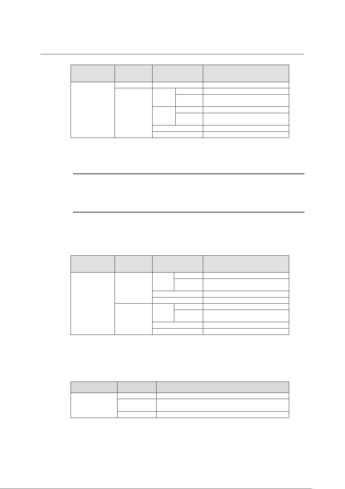
1.5.1 2-port 10G BASE-CX4 interface module (LS-CX2-T2) ......................................... 1-12
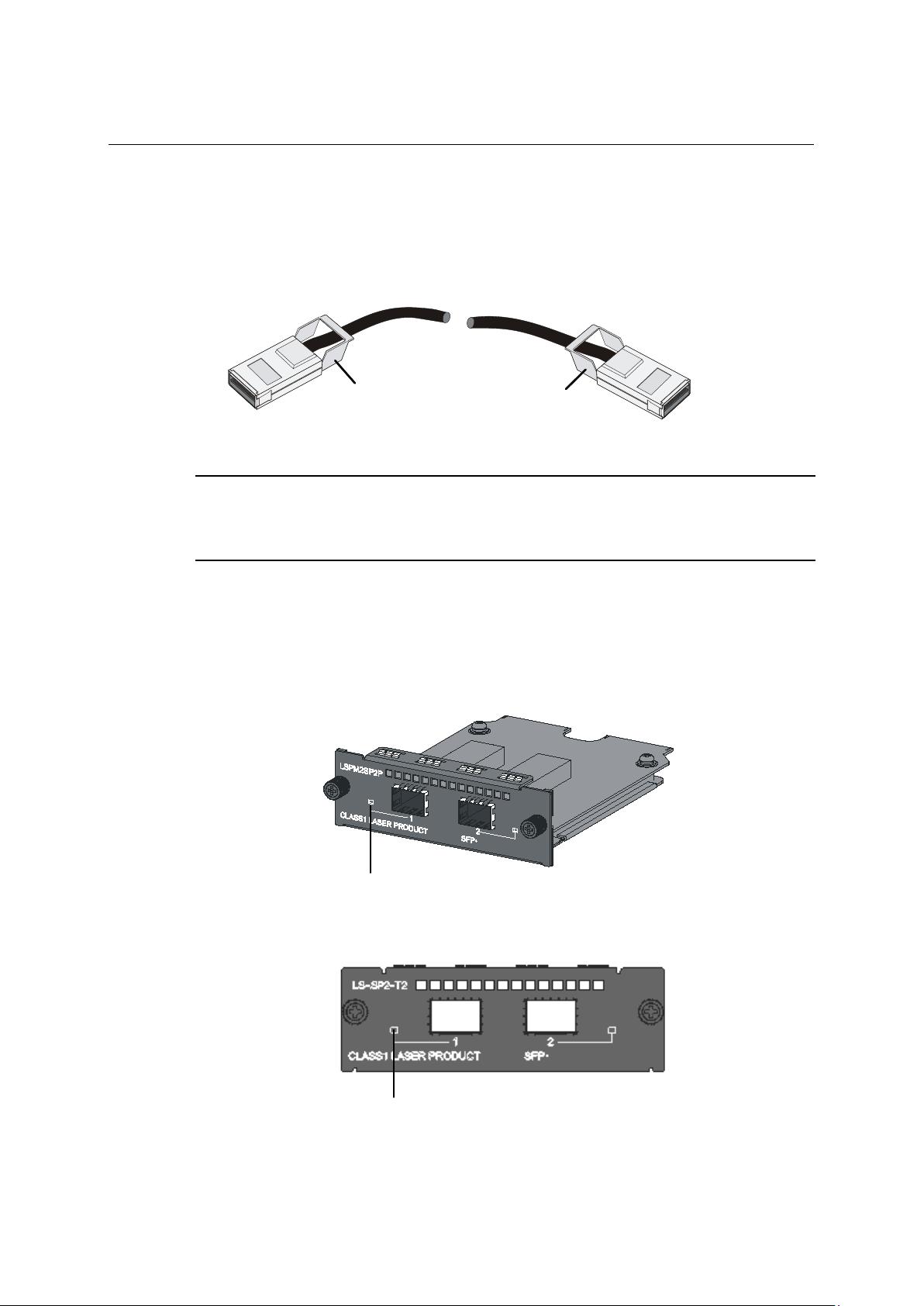
1.5.2 2-port 10G BASE-XFP interface module (LS-SP2-T2) ......................................... 1-13
1.5.3 2-port 10G BASE-XFP interface module (LS-XP2-T2) ......................................... 1-15
1.5.4 1-port 10G BASE-XFP interface module (LS-XP1-T2) ......................................... 1-16
1.5.5 Description of LEDs of Interface Modules ............................................................. 1-16
i
Page 9

Installation Guide
QX-S5500 Series Ethernet Switches
Product overview
Physical dimensions (H
× W × D)
Weight (kg)
max 4.0
max 4.5
max 6.3
Console port
1 (front panel)
Note:
a time. For details about the combo port mapping relationship, please refer to Table 1-5.
2, on the rear panel
Optional hot swappable
power modules
PSR150-A1
PSR150-D1
PSR150-A1: 1 AC
power socket
AC power module: 3m
DC power module: 3m
Input
voltage
Rated voltage range: 100 to 240VAC ; 50/60Hz
Input voltage range: 90 to 264VAC.; dd47/63Hz
1 Product overview
1.1 Overview
QX-S5500 Series Ethernet Switches (hereinafter referred to as the QX-S5500 series) are
Layer 3 Gigabit Ethernet switching products. QX-S5500 series are designed as distribution
or access devices for intranets and metropolitan area networks (MANs). Supporting
IPv4/IPv6 dual stack and 10 GE uplink interfaces, the QX-S5500 series provide abundant
service features and can also be used for connecting server groups in data centers.
QX-S5500 series support the Intelligent Resilient Framework (IRF) technology. You can
connect multiple QX-S5500 switches through 10 GE ports to form a logical entity, thus to
establish a new intelligent network with high reliability, expandability and manageability.
QX-S5500 series include 4 models, and have the system specifications as shown in Table
1-1.
1
Item QX-S5526P-D QX-S5526P QX-S5550P QX-S5526T
GE ports
Interface card models
supported (optional)
Table 1-1 System specifications of the QX-S5500 series
440 x 300 x 43.6 440 x 360 x 43.6
48
24 x 10/100/1000BASE-T
4 x100/1000BASE-X SFP
For each Combo port, either the SFP port or the corresponding Ethernet port can be used at
2-port 10GE CX4 interface module (LS-CX2-T2)
2-port 10 GE SFP+ interface module (LS-SP2-T2)
1-port 10 GE XFP interface module (LS-XP1-T2)
2-port 10 GE XFP interface module (LS-XP2-T2)
1-port 10 GBASE-T interface module (LSPM3XGT2P)
N/A
x10/100/1000BASE-T
4 x100/1000BASE-X
SFP
8 x 10/100/1000BASE-T
24 x100/1000BASE-X
SFP
Power socket types
and quantity
Power cable length 2m 3m 3m
AC
1 DC power
socket
1 AC power
socket
1-1
1 AC power socket
and 1 RPS power
socket
power socket
PSR150-D1: 1 -48V DC
Page 10
Installation Guide
QX-S5500 Series Ethernet Switches
Product overview
Rated voltage range: - 48 VDC to - 60 VDC
Input voltage range: - 36 VDC to - 72 VDC
QX-PS800 is supported.
Input voltage range: 10.8 to 13.2VDC
6 fans (4 for the system,
module)
Operating temperature
0°C to 45°C
Relative humidity
(noncondensing)
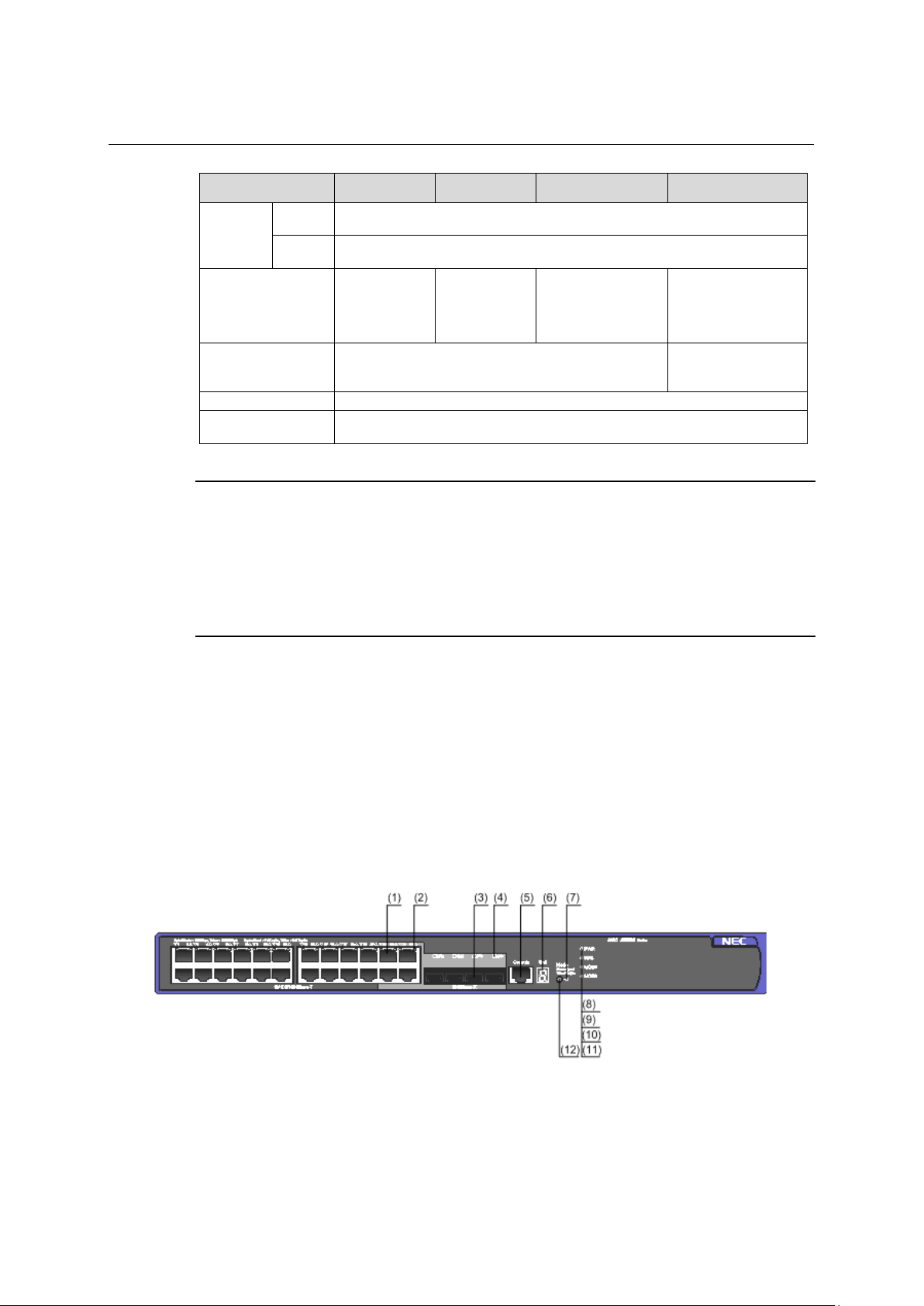
(1) 10/100/1000BASE-T auto-sensing Ethernet port
(2) 10/100/1000BASE-T auto-sensing Ethernet port status LED
(3) 100/1000BASE-X SFP Combo port
(4) 100/1000BASE-X SFP Combo port status LED
(5) Console port
(6) Seven-segment LED
(7) Port mode LED (Mode)
(8) System status LED (PWR)
1
Item QX-S5526P-D QX-S5526P QX-S5550P QX-S5526T
-48V DC
RPS
Power consumption
(full load)
Cooling system 4 fans
NOTE:
2-ports 10GBASE-T interface module (LSPM3XGT2P) is being supported with after software including
Version 5.4.12 or later version.
There are PSR150-A1 and PSR150-A in AC power supply module. There are PSR150-D1 and PSR150-D
in DC power supply module. It's different in a name of product depending on shipment time but same as
power supply module.
A cable length of DC power supply module changes it to 3m from 2m more than 2014 years.
1.2 Panel views
105 W 110 W 155 W 115 W
and 1 for each power
10% to 90%
1.2.1 QX-S5526P panel views
I. Front panel
Figure 1-1 QX-S5526P front panel
1-2
Page 11
Installation Guide
QX-S5500 Series Ethernet Switches
Product overview
(9) RPS status LED (RPS)
(10) Interface module 1 status LED (MOD1)
(11) Interface module 2 status LED (MOD2)
(12) Port status LED mode switching button
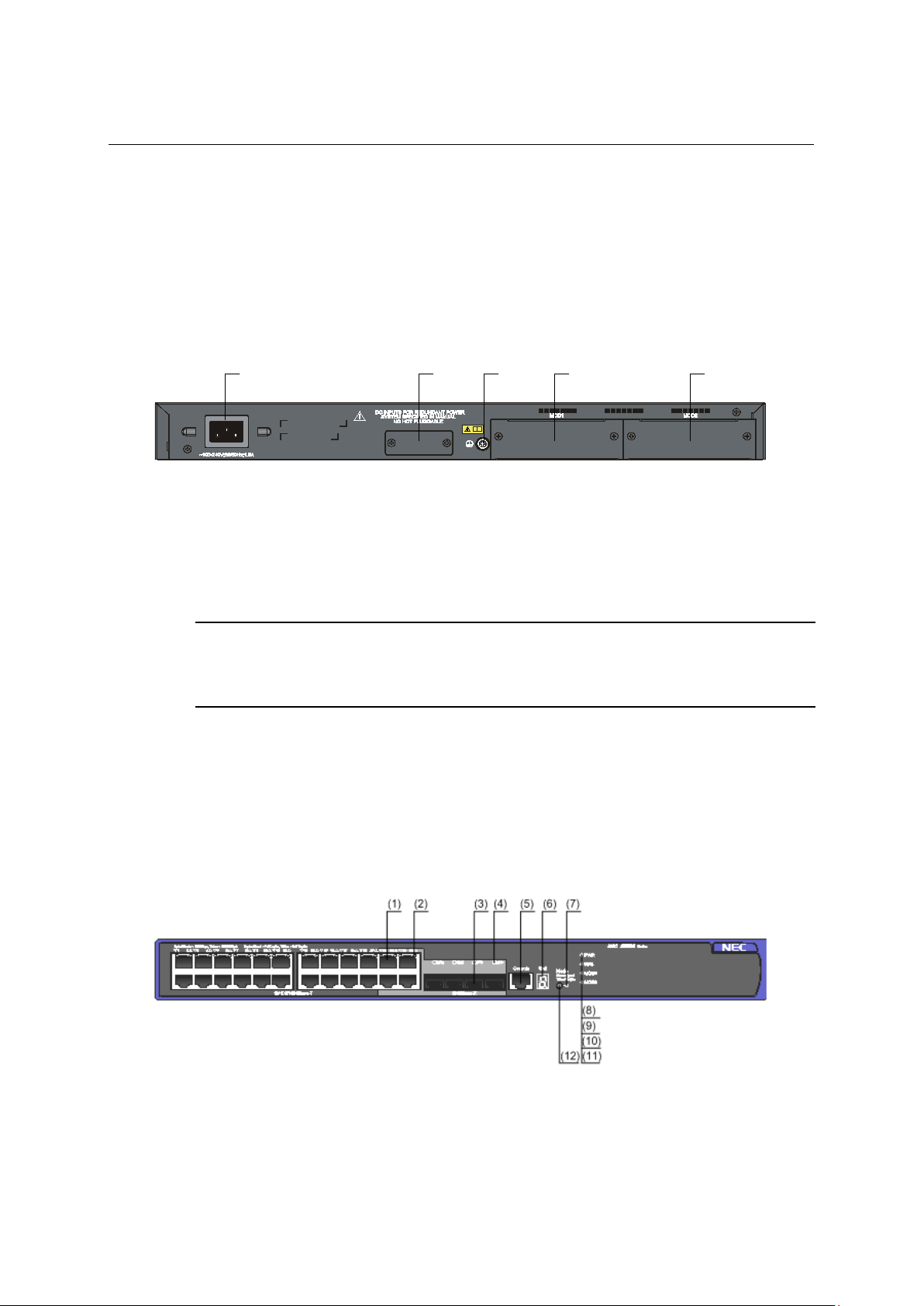
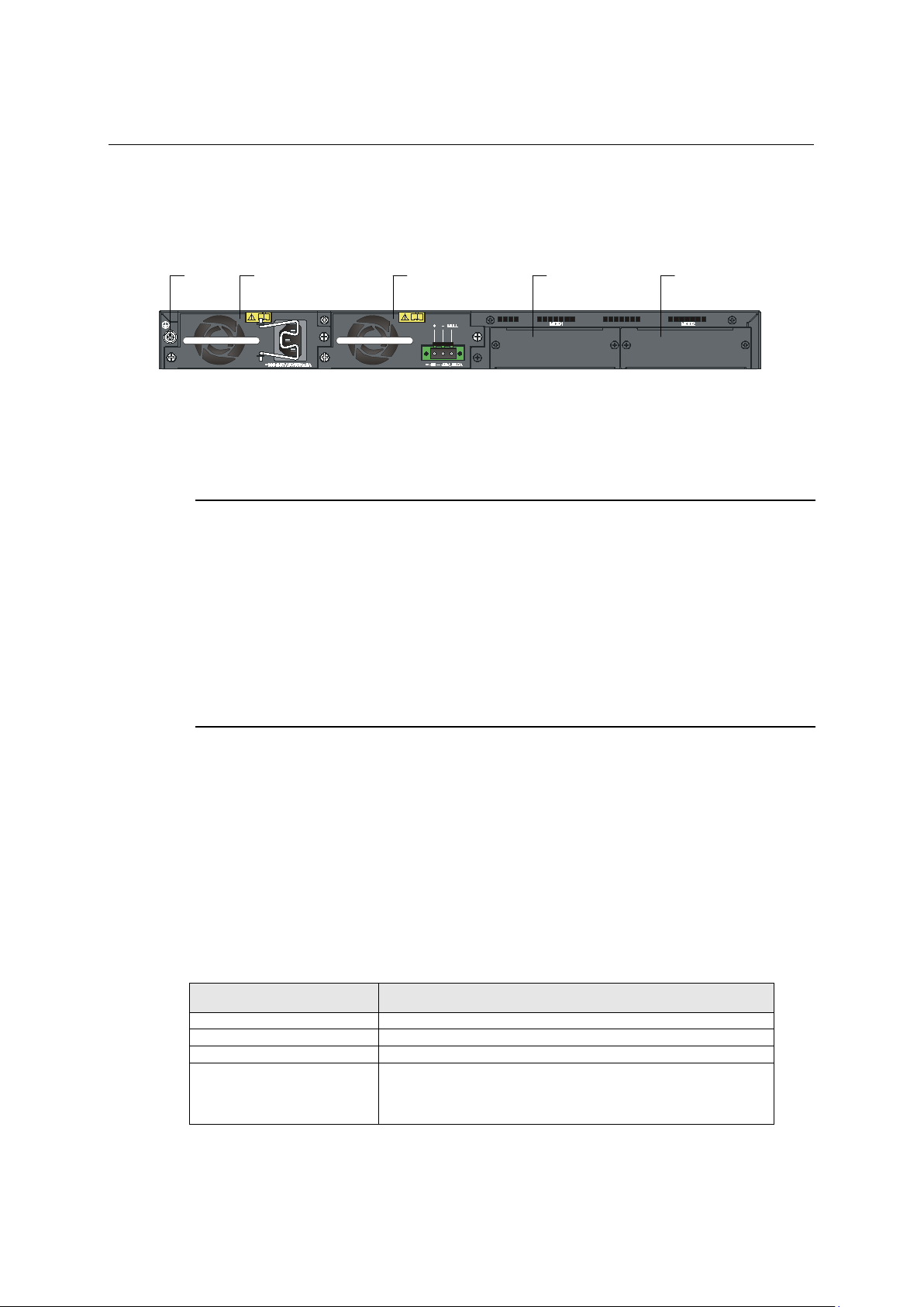
(1) (2) (3) (4) (5)
(1) AC power input
(2) RPS power input
(3) Grounding screw
(4) Interface module slot 1 (MOD1)
(5) Interface module slot 2 (MOD2)
(1) 10/100/1000BASE-T auto-sensing Ethernet port
(2) 10/100/1000BASE-T auto-sensing Ethernet port status LED
(3) 100/1000BASE-X SFP Combo port
(4) 100/1000BASE-X SFP Combo port status LED
(5) Console port
(6) Seven-segment LED
(7) Port mode LED (Mode)
(8) System status LED (PWR)
1
II. Rear panel
Figure 1-2 QX-S5526P rear panel
(It is possible to use a cable tie to secure the power cord to the AC power input.)
NOTE:
Please refer to "Expansion interface module" about a practicable Interface module expansion interface card by
an Interface module slot.
1.2.2 QX-S5526P-D panel views
I. Front panel
Figure 1-3 QX-S5526P-D front panel
1-3
Page 12
Installation Guide
QX-S5500 Series Ethernet Switches
Product overview
(9) RPS status LED (RPS)
(10) Interface module 1 status LED (MOD1)
(11) Interface module 2 status LED (MOD2)
(12) Port status LED mode switching button
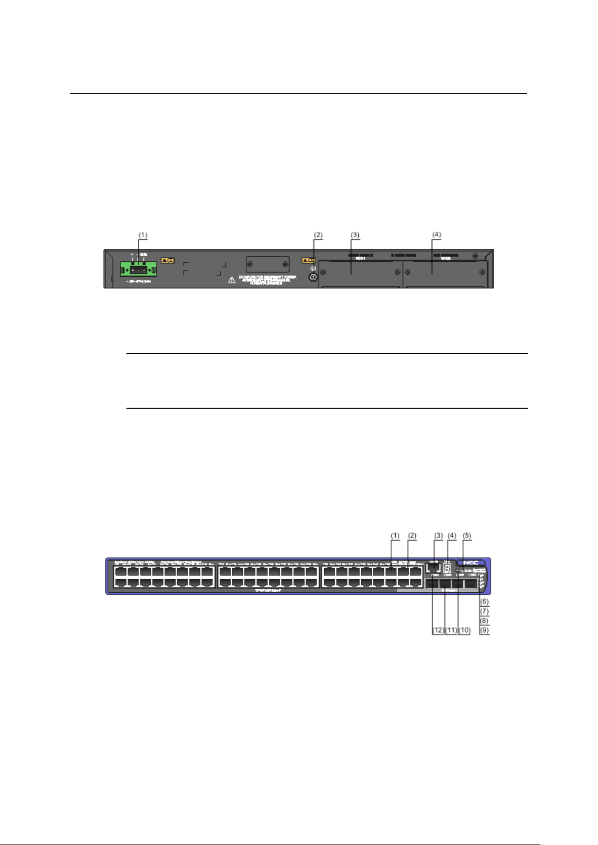
(1) -48V DC power input
(2) Grounding screw
(3) Interface module slot 1 (MOD1)
(4) Interface module slot 2 (MOD2)
(1) 10/100/1000BASE-T auto-sensing Ethernet port
(2) 10/100/1000BASE-T auto-sensing Ethernet port status LED
(3) Console port
(4) Seven-segment LED
(5) Port mode LED (Mode)
(6) System status LED (PWR)
(7) RPS status LED (RPS)
(8) Interface module 1 status LED (MOD1)
(9) Interface module 2 status LED (MOD2)
(10) Port status LED mode switching button
(11) 100/1000BASE-X SFP port
(12) 100/1000BASE-X SFP port status LED
1
II. Rear panel
Figure 1-4 QX-S5526P-D rear panel
NOTE:
Please refer to "Expansion interface module" about a practicable Interface module expansion interface card by
an Interface module slot.
1.2.3 QX-S5550P panel views
I. Front panel
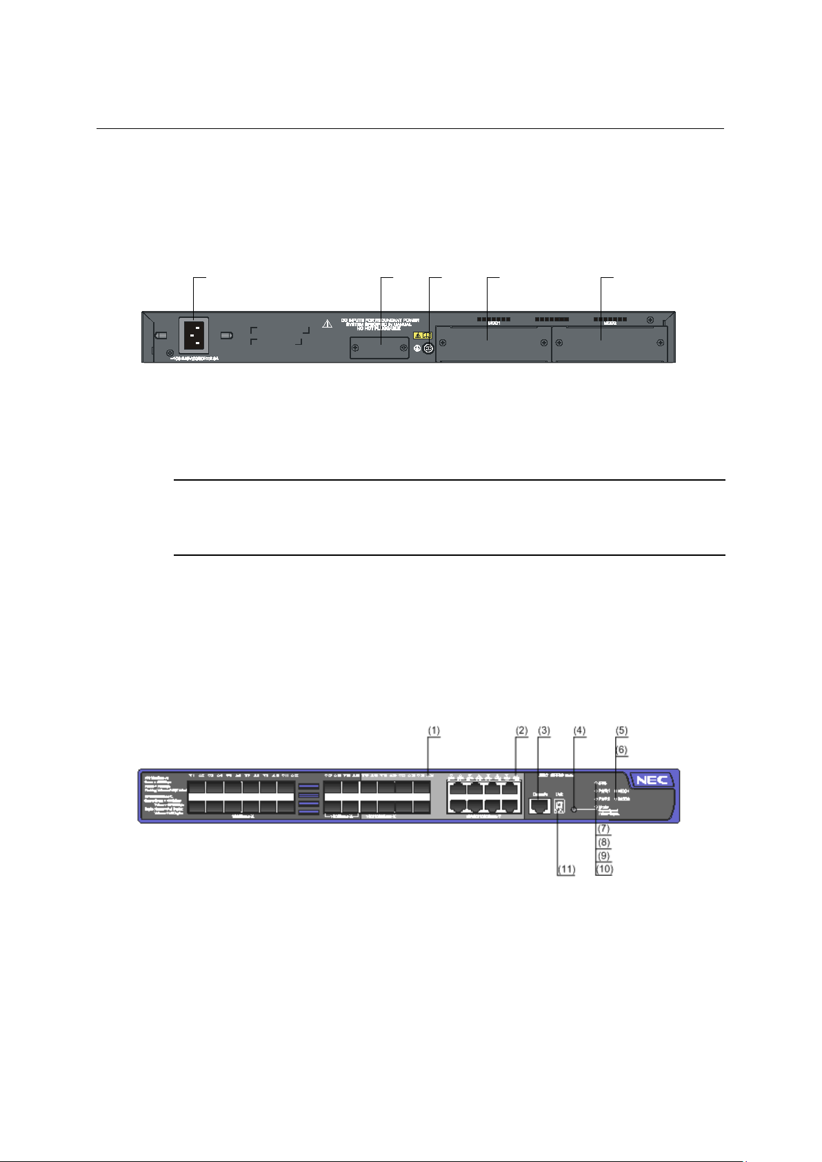
Figure 1-5 QX-S5550P front panel
1-4
Page 13
Installation Guide
QX-S5500 Series Ethernet Switches
Product overview
(
1
)
(
2
)
(3
)
(
4)
(5
)
(1) AC power input
(2) RPS power input
(3) Grounding screw
(4) Interface module slot 1 (MOD1)
(5) Interface module slot 2 (MOD2)
(1) 100/1000BASE-X SFP port status LED
(2) 10/100/1000 BASE-T auto-sensing Ethernet port status LED
(3) Console port
(4) Port status LED mode switching button
(5) Interface module 1 status LED (MOD1)
(6) Interface module 2 status LED (MOD2)
(7) System status LED (SYS)
(8) Hot swappable power module 1 status LED (PWR1)
(9) Hot swappable power module 2 status LED (PWR2)
(10) Port mode LED (Mode)
(11) Seven-segment LED
1
II. Rear panel
Figure 1-6 QX-S5550P rear panel
NOTE:
Please refer to "Expansion interface module" about a practicable Interface module expansion interface card by
an Interface module slot.
1.2.4 QX-S5526T panel views
I. Front panel
Figure 1-7 QX-S5526T front panel
1-5
Page 14
Installation Guide
QX-S5500 Series Ethernet Switches
Product overview
(1)
(2
)
(
3
)
(4
)
(5
)
(1) Grounding screw
(2) Hot swappable power module 1
(3) Hot swappable power module 2
(4) Interface module slot 1 (MOD1)
(5) Interface module slot 2 (MOD2)
Connector type
RJ-45
Compliant standard
EIA/TIA-232
Transmission baud rate
9600 bps to 115200 bps (defaulting to 9600 bps)
1
II. Rear panel
Figure 1-8 QX-S5526T rear panel
NOTE:
The QX-S5526T switch comes with the power module slots empty and the filler modules for the slots as
accessories. You can select AC power module or DC power module for your switch as needed.
You can install one or two power modules for the switch.
The QX-S5526T provides two power module slots on its rear panel, with only an AC power module installed
in Hot swappable power module 1 upon device delivery while a blank panel on Hot swappable power
module 2.
You can install a power module, which can be AC power module or DC power module, in Hot swappable
power module 2 to serve as a backup.
Please refer to "Expansion interface module" about a practicable Interface module expansion interface
card by an Interface module slot.
1.3 Ports
1.3.1 Console Port
Each QX-S5500 series provides one console port on the front panel. Table 1-2 describes
the console port specifications. You can connect console port to a PC and configure,
manage, and monitor the device.
Service
Table 1-2 Console port specifications
Item Specification
It can be connected to an ASCII terminal.
It can be connected to a serial port of a local PC running terminal
emulation program.
1-6
Page 15
Installation Guide
QX-S5500 Series Ethernet Switches
Product overview
QX-S5526P : 24 ports
QX-S5526T : 8 ports
10/100/1000 Mbps, half/full duplex
MDI/MDI-X, auto-sensing
IEEE 802.3 IEEE 802.3u IEEE 802.3ad
IEEE 802.1w IEEE 802.3ab
50/125 μm multi-mode
optical fiber
50/125 μm multi-mode
optical fiber
40 m
70 m
10 km
1000BASE-ZX-LR-SFP
40 km
1000BASE-ZX-VR-SFP
70 km
1000BASE-BX10-D-SFP
1310 nm
10km
1000BASE-BX10-U-SFP
1490nm
10km
1000BASE-BX40-D-SFP
1310 nm
40 km
1000BASE-BX40-U-SFP
1490nm
40 km
1000BASE-T-SFP
N/A
RJ45
Category-5 twisted pair
100m
1.3.2 10/100/1000BASE-T auto-sensing Ethernet port
Each QX-S5500 series provides 10/100/1000Base-T Ethernet ports on its front panel.
Table 1-3 describes the specifications of the 10/100/1000Base-T Ethernet ports.
Table 1-3 10/100/1000Base-T Ethernet port specifications
Item Specification
Connector type RJ-45
1
Number of port
Interface standard
Standard
Transmission medium Category-5 unshielded twisted pair cable
1.3.3 SFP port
QX-S5900 series have fixed SFP ports. You can plug the SFP transceiver modules in Table
1-4 as needed.
Transceiver module
100BASE-FX-SFP 1310 nm LC
1000BASE-SX-SFP 850 nm
QX-S5550P : 48 ports
IEEE 802.3x IEEE 802.1p IEEE 802.1D
IEEE 802.1Q IEEE 802.1X IEEE 802.1s
Table 1-4 1000 Mbps SFP transceiver modules available for the SFP ports
Central
wavelength
Connector Fiber
Max
transmission
distance
2 km
550 m
1000BASE-LX-SFP 1310 nm
NOTE:
To guarantee the functionality of the SFP+ ports, use only NEC SFP transceiver modules.
The SFP transceiver modules available for this switch series are subject to change over time. For the most
up-to-date list of SFP transceiver modules, consult your NEC sales representative or technical support
engineer.
1550 nm
LC
1-7
9/125 μm single-mode
optical fiber
Page 16
Installation Guide
QX-S5500 Series Ethernet Switches
Product overview
GigabitEthernet1/0/25
GigabitEthernet1/0/22
GigabitEthernet1/0/26
GigabitEthernet1/0/24
GigabitEthernet1/0/27
GigabitEthernet1/0/21
GigabitEthernet1/0/28
GigabitEthernet1/0/23
GigabitEthernet1/0/49
GigabitEthernet1/0/46
GigabitEthernet1/0/50
GigabitEthernet1/0/48
GigabitEthernet1/0/51
GigabitEthernet1/0/45
GigabitEthernet1/0/52
GigabitEthernet1/0/47
GigabitEthernet1/0/17
GigabitEthernet1/0/25
GigabitEthernet1/0/18
GigabitEthernet1/0/26
GigabitEthernet1/0/19
GigabitEthernet1/0/27
GigabitEthernet1/0/20
GigabitEthernet1/0/28
GigabitEthernet1/0/21
GigabitEthernet1/0/29
GigabitEthernet1/0/22
GigabitEthernet1/0/30
GigabitEthernet1/0/23
GigabitEthernet1/0/31
GigabitEthernet1/0/24
GigabitEthernet1/0/32
Steady green
The switch is started normally. (powered on)
The system is performing Power-On Self Test (POST) or
downloading software image.
Steady red
POST failed or other system failed.
Flashing yellow (1 Hz)
POST on some ports failed.
Off
The switch is powered off.
1.3.4 Combo Port
One SFP port and the corresponding 10/100/1000Base-T Ethernet port form a Combo port.
For each Combo port, either the SFP port or the corresponding 10/100/1000Base-T
Ethernet port can be used at a time. For details about the combo port mapping relationship,
please refer to Table 1-5.
Model SFP ports 10/10/1000BASE-T ports
QX-S5526P
QX-S5526P-D
QX-S5550P
1
Table 1-5 Combo port mapping relationship
QX-S5526T
NOTE:
The SFP port and its corresponding 10/100/1000Base-T autosensing Ethernet port cannot be used together at
the same time.
1.4 LED
1.4.1 System Status LED
The system status LED helps you determine the working status of the switch. Refer to Table
1-6 for the details.
LED Status Description
Table 1-6 System status LED description
PWR
Flashing green (1 Hz)
1-8
Page 17

Installation Guide
QX-S5500 Series Ethernet Switches
Product overview
Hot swappable power module slot 1 is installed with a power
module, and the power output is normal.
Hot swappable power module slot 1 is installed with a power
module, but an output failure occurs.
No power module is installed in hot swappable power module
slot 1, or no power is input.
Hot swappable power module slot 2 is installed with a power
module, and the power output is normal.
Hot swappable power module slot 2 is installed with a power
module, but an output failure occurs.
No power module is installed in hot swappable power module
slot 2, or no power is input.
Steady green
QX-PS800 is connected right, and is a standby.
Steady yellow
Electricity is supplied by QX-PS800.
Off
QX-PS800 is abnormal (powered off) or is not connected.
Steady green
Indicates port rate.
Steady yellow
Indicates port duplex mode.
1.4.2 Hot Swappable Power Module Status LEDs
The hot swappable power module status LEDs help you determine the working status of a
hot swappable power module. Only the QX-S5526T supports this type of LEDs. Refer to
Table 1-7 for details.
Table 1-7 Description of the hot swappable power module LEDs
LED Status Description
Steady green
1
PWR1
PWR2
1.4.3 RPS Status LED
The RPS status LED helps you determine the working status of the RPS of the switch.
Refer to Table 1-8 for details.
QX-S5526T not supports this type of LEDs.
LED Status Description
RPS
Steady yellow
Off
Steady green
Steady yellow
Off
Table 1-8 RPS status LED
1.4.4 Port Mode LED
The port mode LED on the QX-S5500 series can display the working status of a port for you
to obtain more device information. You can use the port mode switching button to change
the status of the port mode LED.
LED Status Description
Mode
Table 1-9 Port mode LED description
1-9
Page 18
Installation Guide
QX-S5500 Series Ethernet Switches
Product overview
The LED displays the specific numbers one
The LED flashes the specific numbers.
A bar rotates clockwise around the LED.
The LED flashes F.
The LED flashes t.
The LED displays the specific numbers
Steady
The port operates at a rate of 1000 Mbps.
The data is being sent and/or received on
the port.
The port operates at a rate of 10/100
Mbps.
The data is being sent and/or received on
the port.
Flashing green (3 Hz)
POST failed on the port.
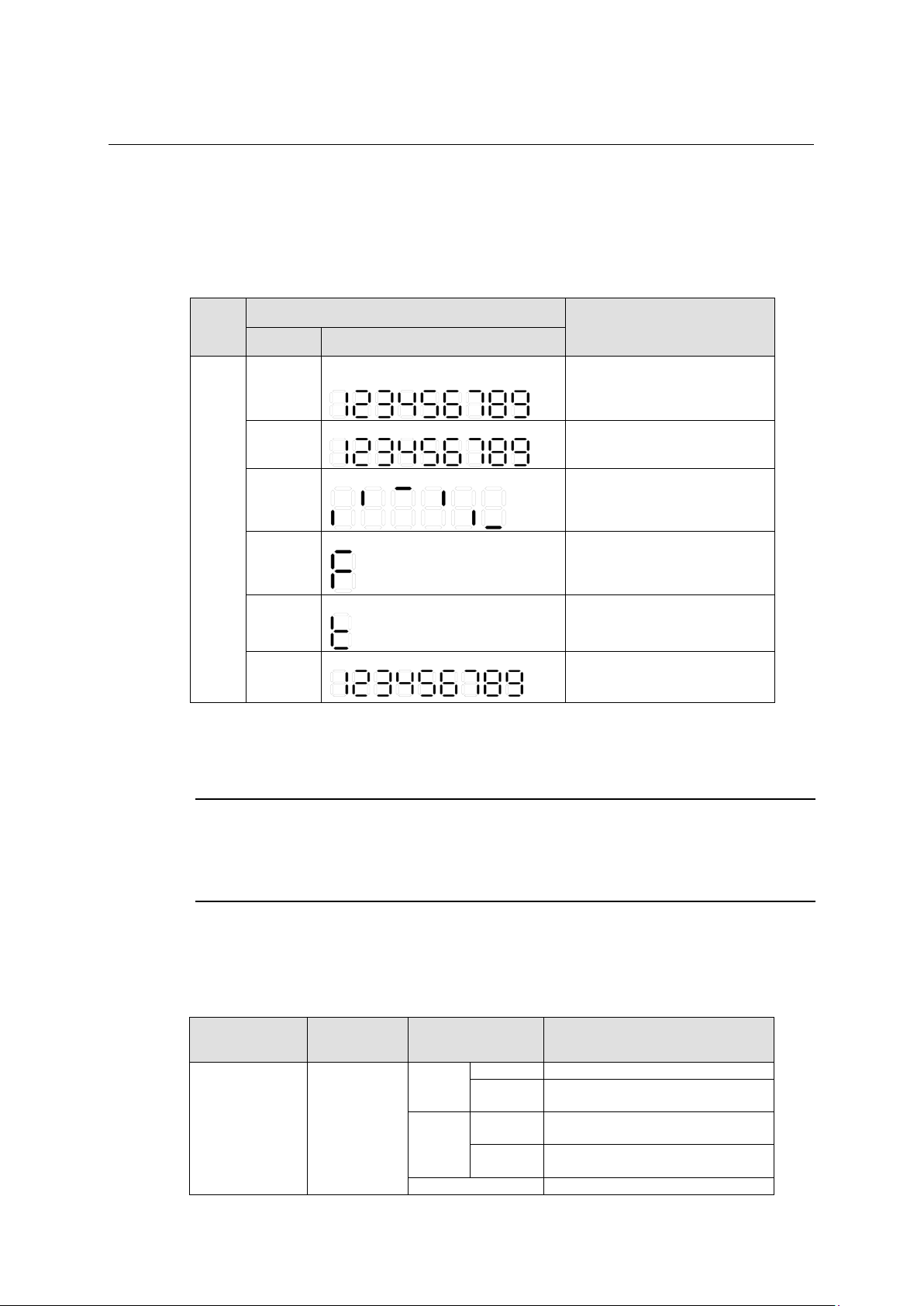
1.4.5 Seven-Segment LED
The seven-segment LED and the system status LED together indicate the operating status
of the device. For details, refer to Table 1-10
1
Table 1-10 Seven-segment LED description
LED
Unit
Status
SYS LED Seven-segment LED
Flashing
green
Flashing
red
Flashing
green
Steady red
Steady red
Steady
green
by one.
Description
POST running. The LED displays the
POST test ID.
POST failed. The LED flashes the
POST test ID of the failed test.
Software loading
Fan failure
Over-temperature alarm
The LED displays the member ID.
1.4.6 10/100/1000Base-T Auto-Sensing Ethernet Port Status LED
NOTE:
At software Version 5.4.16 or later Version, when a loop was detected at the port where a loopback detection
feature is effective, while port mode is rate mode or duplex mode Ethernet Port Status LED flashes on and off
by the cycle for about 2 seconds greenly.
The port mode LED and the 10/100/1000Base-T auto-sensing Ethernet port status LED
together indicate the port operation status. Refer to Table 1-11 for details.
Table 1-11 10/100/1000Base-T auto-sensing Ethernet port LEDs description
LED Port mode LED
10/100/1000
BASE-T port status
LED
Steady green
(rate mode)
Ethernet port status
LED
green
yellow
Flashing
Steady
Flashing
1-10
Description
Page 19
Installation Guide
QX-S5500 Series Ethernet Switches
Product overview
Off
The port is not up.
Steady
The port operates in full-duplex mode.
The data is being sent and/or received on
the port.
Steady
The port operates in full-duplex mode.
The data is being sent and/or received on
the port.
Flashing yellow (3 Hz)
POST failed on the port.
Off
The port is not up.
Steady
The port operates at a rate of 1000 Mbps.
The data is being sent and/or received on
the port.
Flashing yellow (3 Hz)
POST failed on the port.
Off
The port is not up.
Steady
The port operates in full-duplex mode.
The data is being sent and/or received on
the port.
Flashing yellow (3 Hz)
POST failed on the port.
Off
The port is not up.
Steady green
The interface module is in the slot and operates normally.
The inserted interface module type is incorrect or the interface
module fails.
Off
No interface module is installed.
1
LED Port mode LED
Ethernet port status
LED
Description
Steady yellow
(duplex mode)
green
yellow
Flashing
Flashing
1.4.7 100/1000BASE-X SFP Port Status LED
NOTE:
At software Version 5.4.16 or later Version, when a loop was detected at the port where a loopback detection
feature is effective, while port mode is rate mode or duplex mode Ethernet Port Status LED flashes on and off
by the cycle for about 2 seconds greenly.
The port mode LED and the SFP port status LED together indicate the SFP port operation
status. Refer to Table 1-12 for details.
Table 1-12 100/1000BASE-X SFP port status LEDs description
LED Port mode LED
Ethernet port status
LED
Description
Steady green
(rate mode)
100/1000 BASE-T
port status LED
Steady yellow
(duplex mode)
1.4.8 Interface Module Status LED
Table 1-13 Interface module status LED description
LED Status Description
MOD1
MOD2
Steady yellow
green
green
Flashing
Flashing
1-11
Page 20
Installation Guide
QX-S5500 Series Ethernet Switches
Product overview
2-port 10G BASE-Cx4 interface
module
It's suitable for a short distance connection using
CX4 cable.
A short distance connection using SFP+ copper
optical module is possible.
2-port 10G BASE-XFP interface
module
1-port 10G BASE-XFP interface
module
Port LED
Port LED
1.5 Optional Interface Modules
QX-S5500 series provide two interface module slots on the rear panel. You can select the
interface modules in Table 1-14 as needed.
QX-S5500 series support IRF, requiring physical connections between devices. The 10 GE
ports of the supported interface modules support IRF, allowing you to connect the switches
through these 10 GE ports for IRF implementation.
Table 1-14 Description of the supported interface modules
Model Description Remarks
LS-CX2-T2
1
LS-SP2-T2
LS-XP2-T2
LS-XP1-T2
2-port 10G BASE-SFP+ interface
module
cable or a long distance connection using SFP+
A long distance connection using XFP optical
module is possible.
1.5.1 2-port 10G BASE-CX4 interface module (LS-CX2-T2)
Figure 1-9 2-port 10G BASE-CX4 interface module (LS-CX2-T2)
A 2-port 10 GE CX4 interface module provides two 10 Gbps electrical ports and supports
CX4 electrical and protocol standards. Only NEC's CX4 cables can be used for connecting
the CX4 ports. A CX4 cable is hot swappable and its maximum transmission distance is 3 m,
which is suitable for short-distance connections only.
Figure 1-10 2-port 10G BASE-CX4 interface module front panel(LS-CX2-T2)
1-12
Page 21
Installation Guide
QX-S5500 Series Ethernet Switches
Product overview
Handle Handle
Connector 1
Connector 2
Port LED
Port LED
1
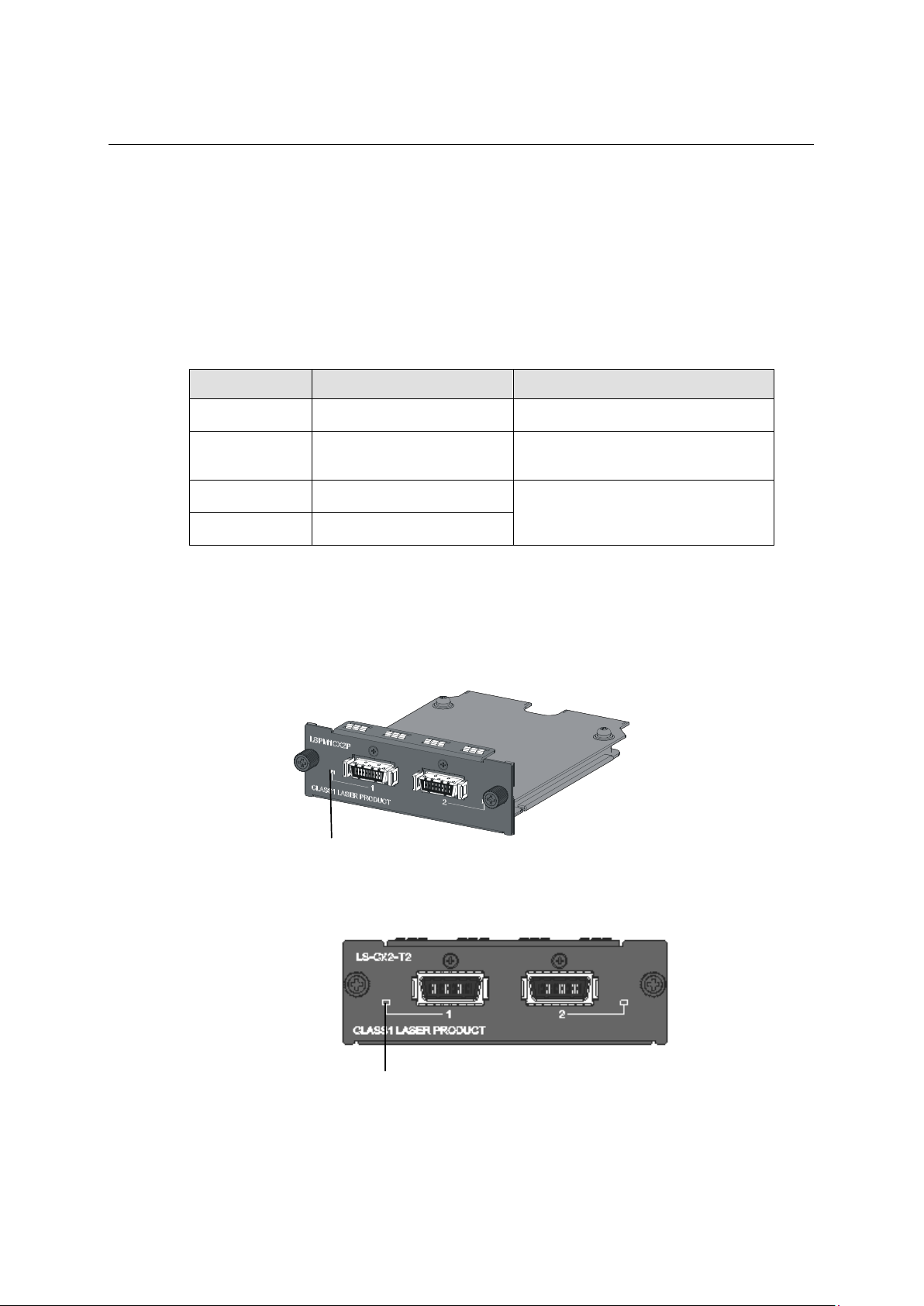
Following CX4 cables supported by the 2-port 10 GE CX4 interface module
10GBASE-CX4 cable A(50cm) [CAB-CX4T2-50CM]
10GBASE-CX4 cable B(100cm) [CAB-CX4T2-100CM]
10GBASE-CX4 cable C(300cm) [CAB-CX4T2-300CM]
Figure 1-11 CX4 cable
NOTE:
The CX4 cable isn't attached to the 2-port 10G BASE-CX4 interface module (LS-CX2-T2). When using the CX4
cable, it's necessary to buy the CX4 cable separately.
1.5.2 2-port 10G BASE-XFP interface module (LS-SP2-T2)
Figure 1-12 2-port 10G BASE-XFP interface module (LS-SP2-T2)
Figure 1-13 2-port 10G BASE-XFP interface module front panel (LS-SP2-T2)
1-13
Page 22
Installation Guide
QX-S5500 Series Ethernet Switches
Product overview
50/125 μm
fiber
9/125 μm single-mode
optical fiber
9/125 μm single-mode
optical fiber
10GE
cable
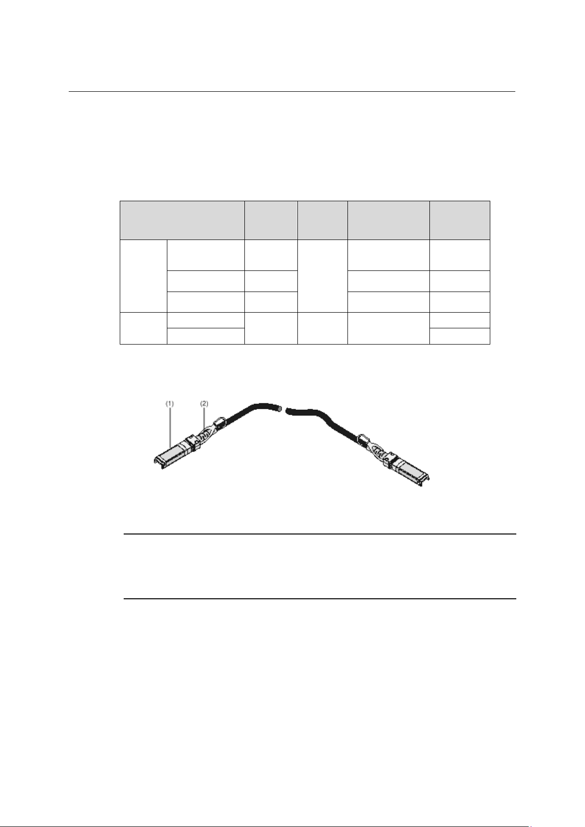
(1) Connector
(2) Handle
1
A 2-port 10G BASE-XFP interface module provides two 10 Gbps SFP+ ports. You can
insert an SFP+ transceiver into the port to connect it to another SFP+ port through an
optical fiber, or an SFP+ cable provided by NEC.
For details about the supported SFP+ transceivers and SFP+ cables, refer to Table 1-15.
Table 1-15 SFP+ transceivers and SFP+ cables supported by 2-port 10 GE SFP+ interface
module
Transceiver/Cable type
10GBASE-SR-SFP+ 850 nm
10GE
SFP+
transceiver
SFP+
10GBASE-LR-SFP+ 1310 nm
10GBASE-ER-SFP+ 1550 nm
CAB-1M-SFP+
CAB-3M-SFP+ 3 m
Central
wavelength
N/A N/A SFP+ cable
Connector Fiber
multi-mode optical
LC
Figure 1-14 SFP+ cable
Max
transmission
distance
300 m
10 km
40 km
1 m
NOTE:
You must use SFP+ transceivers and SFP+ cables of the QX series.
The types of SFP+ transceivers and SFP+ cables may update with time. For information about transceivers,
contact NEC technical support or marketing staff.
1-14
Page 23
Installation Guide
QX-S5500 Series Ethernet Switches
Product overview
50/125 μm multi-mode
optical fiber
10GBASE-LR-XFP
1310 nm
9/125 μm single-mode
optical fiber
10 km
10GBASE-ER-XFP
1550 nm
40 km
Port LED
Port LED
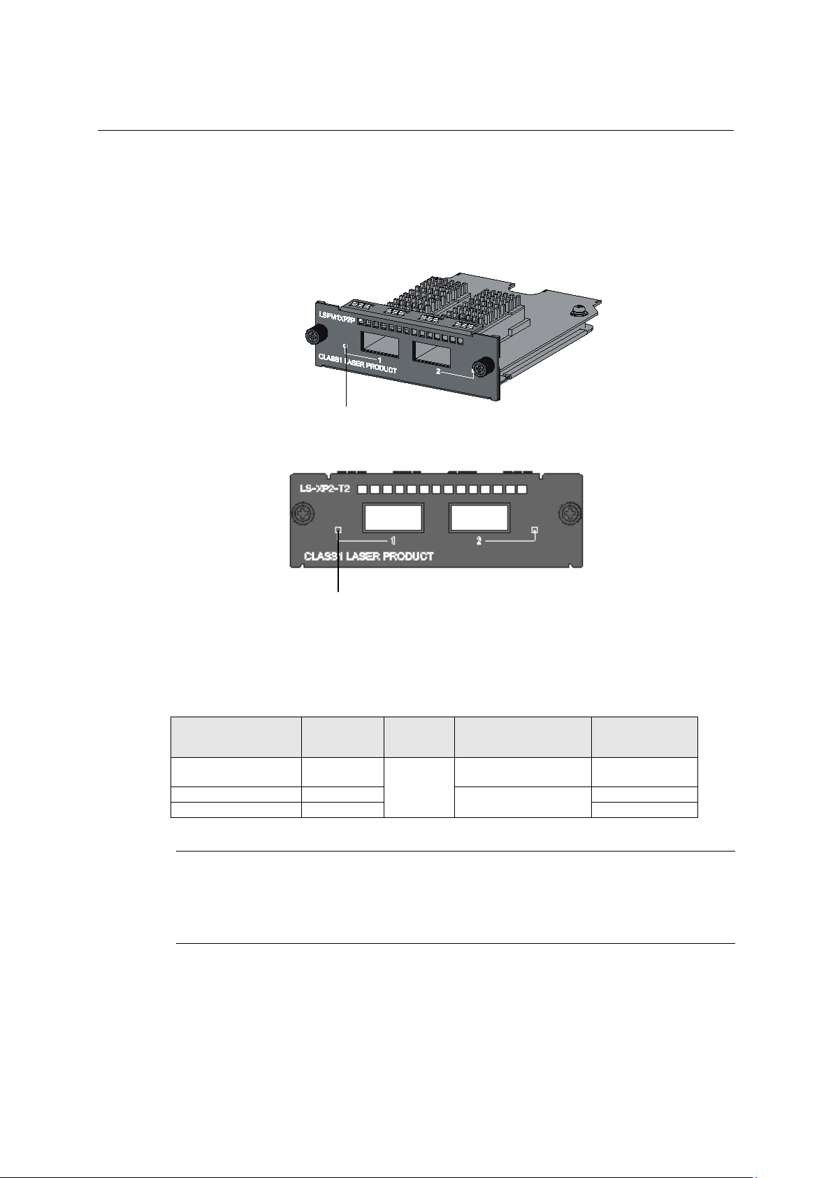
1.5.3 2-port 10G BASE-XFP interface module (LS-XP2-T2)
Figure 1-15 2-port 10G BASE-XFP interface module (LS-XP2-T2)
Figure 1-16 2-port 10G BASE-XFP interface module front panel (LS-XP2-T2)
1
A 2-port 10 GE XFP interface module provides two 10 Gbps XFP optical ports. You can
insert an XFP transceiver into the port to connect it to another XFP port through an optical
fiber. You can select the following XFP transceivers in Table 1-16 as required.
Table 1-16 XFP transceivers supported by 10 GE XFP interface module
Transceiver
10GBASE-SR-XFP 850 nm
Central
wavelength
Connector Fiber
LC
Max transmission
distance
300 m
NOTE:
You must use XFP transceivers of the QX series.
The types of XFP transceivers may update with time. For information about transceivers, contact NEC
technical support or marketing staff.
1-15
Page 24
Installation Guide
QX-S5500 Series Ethernet Switches
Product overview
Port LED
Port LED
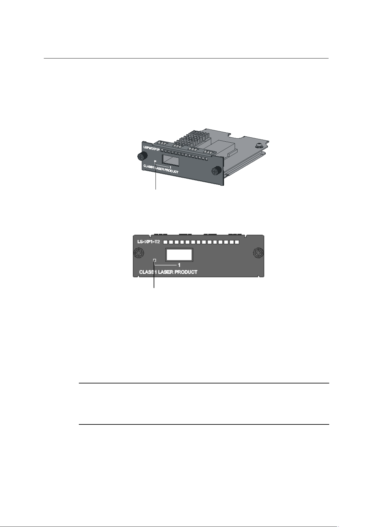
1.5.4 1-port 10G BASE-XFP interface module (LS-XP1-T2)
Figure 1-17 1-port 10G BASE-XFP interface module (LS-XP1-T2)
Figure 1-18 1-port 10G BASE-XFP interface module front panel (LS-XP1-T2)
1
This module provides one 10 Gbps XFP optical interface. You can select the following XFP
transceivers as required. A 1-port 10 GE XFP interface module provides one 10 Gbps XFP
optical port. You can insert an XFP transceiver into the port to connect it to another XFP
port through an optical fiber. You can select the XFP transceivers list in Table 1-16 as
required.
1.5.5 Description of LEDs of Interface Modules
NOTE:
At software Version 5.4.16 or later Version, when a loop was detected at the port where a loopback detection
feature is effective, while port mode is rate mode or duplex mode Ethernet Port Status LED flashes on and off
by the cycle for about 2 seconds greenly.
There is a LED for each port on the interface module panel. Table 1-17 describes the LEDs.
1-16
Page 25

Installation Guide
QX-S5500 Series Ethernet Switches
Product overview
Steady
green
Flashing
green
Off
The port is not up.
1
Table 1-17 Description of LEDs on interface modules
LED Mark Status Description
The port is normally connected.
Port LED of an interface
module
—
The port is sending or receiving data.
NOTE:
For details about the port mode switching button, see "Port Mode LED".
1-17
Page 26

Installation Guide
QX-S5500 Series Ethernet Switches
Contents
Contents
2 Preparing for installation ........................................................................................................... 2-1
2.1 Safety recommendations ................................................................................................... 2-1
2.2 Connecting the RJ45 connector ........................................................................................ 2-1
2.3 Examining the installation site ........................................................................................... 2-2
2.4 Temperature/humidity ........................................................................................................ 2-2
2.5 Cleanness .......................................................................................................................... 2-3
2.6 EMI ..................................................................................................................................... 2-3
2.7 Laser safety ....................................................................................................................... 2-3
2.8 Installation tools ................................................................................................................. 2-4
i
Page 27

Installation
Guide
QX-S5500 Series Ethernet Switches
Preparing for installation
2 Preparing for installation
2.1 Safety recommendations
To avoid any equipment damage or bodily injury caused by improper use, read the
following safety recommendations before installation. Note that the recommendations do
not cover every possible hazardous condition.
Regarding with installation and maintenance of this product, please make the engineer who
acquired a right operating method to do that.
Remove dust on and around the Switch regularly.
Before cleaning the switch, unplug all power cords from the switch. Do not clean the
switch with wet cloth or liquid.
Before moving the Switch, unplug all power cords from the switch.
Do not place the switch near water or in a damp environment. Prevent water or
moisture from entering the switch chassis.
Do not place the switch on an unstable case or desk. The switch might be severely
damaged in case of a fall.
Ensure proper ventilation of the equipment room and keep the air inlet and outlet vents
of the switch free of obstruction.
Connect the yellow-green protection grounding cable before power-on.
Make sure the operating voltage is in the required range.
Please don't open equipment. Breakdowns when opening, will be applying of the
guarantee.
When replacing FRUs, including power modules and fan trays, wear an
ESD-preventive wrist strap to avoid damaging the units.
Please be sure to do service operation of the equipment which is being used after a
power supply is off.
2
2.2 Connecting the RJ45 connector
NOTE:
When connecting the RJ45 cable, wear a wrist strap to protect against static electricity.
Do not touch the RJ45 Ethernet cable terminal. If you touch the RJ45 Ethernet cable
terminal which is connecting to the Switch, the interface circuit may be broken by the static
electricity. When you connect the Console cable, you need also a same care.
2-1
Page 28

Installation
Guide
QX-S5500 Series Ethernet Switches
Preparing for installation
2
Figure 2-1 Connecting the RJ45 connector
2.3 Examining the installation site
The QX-S5500 Series switches must be used indoors.
Mount your switch in a rack or on a workbench and make sure:
Adequate clearance is reserved at the air inlet and exhaust vents for ventilation.
The rack or workbench has a good ventilation system.
Identify the hot aisle and cold aisle at the installation site, and make sure ambient air
flows into the switch from the cold aisle and exhausts to the hot aisle.
Identify the airflow designs of neighboring devices, and prevent hot air flowing out of
the bottom device from entering the top device.
The rack is sturdy enough to support the switch and its accessories.
The rack is well earthed.
To ensure normal operation and long service life of your switch, install it in an environment
that meets the requirements described in the following subsections.
2.4 Temperature/humidity
Maintain appropriate temperature and humidity in the equipment room.
Lasting high relative humidity can cause poor insulation, electricity creepage,
mechanical property change of materials, and metal corrosion.
Lasting low relative humidity can cause washer contraction and ESD and bring
problems including loose captive screws and circuit failure.
High temperature can accelerate the aging of insulation materials and significantly
lower the reliability and lifespan of the switch.
For the temperature and humidity requirements of different switch models, see "Overview".
2-2
Page 29

Installation
Guide
QX-S5500 Series Ethernet Switches
Preparing for installation
Dust ≤ 3 x 10⁴ (no visible dust on the tabletop over three days)
Note:
Dust diameter ≥ 5 μm
SO
2
0.2
H2S
0.006
NH3
0.05
Cl2
0.01
2.5 Cleanness
Dust buildup on the chassis may result in electrostatic adsorption, which causes poor
contact of metal components and contact points, especially when indoor relative humidity is
low. In the worst case, electrostatic adsorption can cause communication failure.
The equipment room must also meet strict limits on salts, acids, and sulfides to eliminate
corrosion and premature aging of components, as shown in Table 2-2.
2
Table 2-1 Dust concentration limit in the equipment room
Substance Concentration limit (particles/m³)
Table 2-2 Harmful gas limits in the equipment room
Gas Maximum concentration (mg/m3)
2.6 EMI
All electromagnetic interference (EMI) sources, from outside or inside of the switch and
application system, adversely affect the switch in a conduction pattern of capacitance
coupling, inductance coupling, electromagnetic wave radiation, or common impedance
(including the grounding system) coupling. To prevent EMI, take the following actions:
Please take the effective measures to reduce the intervention the power supply
system exerts on the switch.
Keep the switch far away from high-power radio launchers, radars, and equipment
with high frequency or high current.
If AC power is used, use a single-phase three-wire power receptacle with protection
earth (PE) to filter interference from the power grid.
Keep the switch far away from radio transmitting stations, radar stations, and
high-frequency devices.
Use electromagnetic shielding, for example, shielded interface cables, when
necessary.
Route interface cables only indoors to prevent signal ports from getting damaged by
overvoltage or overcurrent caused by lightning strikes.
2.7 Laser safety
The QX-S5500 Series switches are Class 1 laser devices.
2-3
Page 30

Installation
Guide
QX-S5500 Series Ethernet Switches
Preparing for installation
WARNING!
Do not stare into any fiber port when the switch has power. The laser light emitted from the optical fiber may
hurt your eyes.
2.8 Installation tools
Flathead screwdriver
Phillips screwdriver
ESD-preventive wrist strap
NOTE:
All these installation tools are user supplied.
2
2-4
Page 31

Installation Guide
QX-S5500 Series Ethernet Switches
Contents
Contents
3 Installing the Switch ................................................................................................................... 3-1
3.1 Installation of hardware ...................................................................................................... 3-1
3.1.1 Installing the Switch into a 19-Inch Rack Using Mounting Brackets ....................... 3-1
3.1.2 Mounting the Switch on a Workbench..................................................................... 3-2
3.2 Connecting the Power Cords and the Grounding Cable ................................................... 3-2
3.2.1 Connecting the AC Power Cable ............................................................................ 3-2
3.2.2 Connecting the -48V DC Power Cord ..................................................................... 3-4
3.2.3 Grounding the Grounding Cable ............................................................................. 3-5
3.3 Connecting the Console Cable .......................................................................................... 3-5
3.3.1 Console Cable ......................................................................................................... 3-5
3.3.2 Connection Procedure............................................................................................. 3-6
3.4 Checklist after installation .................................................................................................. 3-7
i
Page 32

Installation Guide
QX-S5500 Series Ethernet Switches
Installing the Switch
3
3 Installing the Switch
3.1 Installation of hardware
3.1.1 Installing the Switch into a 19-Inch Rack Using Mounting Brackets
An installation procedure is explained below.
NOTE:
Mounting brackets of this switch standard attachment, the EIA standard, it corresponds to 19-inch standard
cabinet based.
Follow these steps to mount a switch into a 19-inch standard cabinet:
1) Wear an ESD-preventive wrist strap and ensure a good skin contact and grounding.
2) Check the grounding and stability of the cabinet.
3) Take out the screws which are packed together with the front mounting brackets, and
fix one end of mounting brackets to the switch, as shown in Figure 3-1.
Figure 3-1 Fix front mounting brackets
3-1
Page 33

Installation Guide
QX-S5500 Series Ethernet Switches
Installing the Switch
I. Mounting method of bracket for fronts
Front mounting bracket screw
QX-S5500 Series Ethernet Switches has one front mounting position (near the network
ports) and one rear mounting position (near the power modules). It's possible to install front
mounting brackets for rear mounting position. Please choose front mounting position and
the rear mounting position according to the installation requirements.
3
Figure 3-2 Mounting method of a front mounting bracket
Front mounting bracket
3.1.2 Mounting the Switch on a Workbench
In many cases, standard 19-inch racks are not available. Therefore, switches are often
placed on clean workbenches. To place your switch on a workbench, you simply need to:
Make sure that the workbench is clean, flat, and sturdy.
Make sure that the environment is well ventilated and allows 10 cm of space around
the chassis for heat dissipation.
Do not place heavy objects on your switch.
The vertical distance between two switches must be at least 1.5 cm.
3.2 Connecting the Power Cords and the Grounding Cable
3.2.1 Connecting the AC Power Cable
I. AC power socket (recommended)
You are recommended to use a single-phase three-wire power socket with a neutral point
or a multifunctional PC power socket. Make sure that the socket is furnished with an
over-current protection device such as air switch and that the neutral point is well
connected to building ground. Normally, the neutral point of the power source in a building
has been buried in the ground during construction and cable routing. Still, you must make
sure that the power source of the build is reliably grounded.
3-2
Page 34

Installation Guide
QX-S5500 Series Ethernet Switches
Installing the Switch
Neutral point
Zero line
Live line
Neutral point
Zero line
Live line
100VAC, 120VAC,
220-230VAC, 240VAC
IEC-320-C13
3
Figure 3-3 Power socket (recommended)
II. Connecting the AC Power Cable
1) Connect one end of the grounding cable to the grounding screw on the rear of the
chassis and the other end to the ground as near as possible.
2) Connect one end of the power cable to the power socket on the rear panel, and the
other end to the AC power supply.
3) Install the power cable retainer for the AC power cable. Insert the two ends of the
power cable retainer into the slots at both sides of the AC power socket, and then set
the power cable into the notch of the power cable retainer.
NOTE:
When connecting AC power cord to equipment, if light resistance is felt after cable insertion, please give
more a push and insert to the inside.
To make sure that the power cable won't be omitted, please install an AC cable retainer of an option.
WARNING:
Make sure that the ground wire has been properly connected before powering on the
switch.
Use the AC power cord which comply the standard of each country.
The socket-outlet shall be installed near the equipment and shall be easily accessible.
For the cables complying with our specifications, see Table 3-1, and Table 3-2.
Table 3-1 AC Input Power Specifications
Input Voltage Current (Max.) Phase Frequency (Hz)
10A/5A Single 50/60
Table 3-2 Power Cable Specifications
Connector(on the Device Side) Cable Ratings Cable Length Plug(Power Facility)
125V, 10A
Comply the standard of
each country
3-3
Comply the standard of
each country
Page 35

Installation Guide
QX-S5500 Series Ethernet Switches
Installing the Switch
IEC-320-C13
3
Connector(on the Device Side) Cable Ratings Cable Length Plug(Power Facility)
250V, 10A
Comply the standard of
each country
3.2.2 Connecting the -48V DC Power Cord
CAUTION:
Before connecting to DC power cord, disconnect the switch and a power supply.
QX-S5526P-D and PSR150-D1 of the QX-S5526T have a –48 VDC power receptacle,
allowing the use of the –48 VDC power supply in the equipment room.
Follow these steps to connect a –48V DC power cord to the switch:
1) Please install an appropriate ring terminal which matches the outside power supply in
the DC power supply side terminal for power cord.
2) Please be careful for the one of the switch connection side connector of power cord.
Please connect a plug to DC power receptacle of the switch. (When the direction of the
connector shape is wrong, to avoid connection mistakes it cannot stick in a DC power
receptacle.)
3) Use a flat-blade screwdriver to fix the two screws on the DC plug clockwise to secure
the plug to the DC receptacle. Connect the other end of the DC power cord to the
external -48 VDC equipment-room power supply system. A black code grounds GND
(-48V.) blue or a white code is connected to a terminal for-48V.
4) Check whether the system status LED (PWR/SYS) on the front panel of the switch is
ON. If yes, the power is properly connected.
Comply the standard of
each country
Figure 3-4 Attachment DC power cable(left: QX-S5526P-D, right: PSR150-D1 of the QX-S5526)
3-4
Page 36

Installation Guide
QX-S5500 Series Ethernet Switches
Installing the Switch
(1) Power cable fixed screw
(2) The power supply handle
(3) Power module fixed screw
(4) G : -48V Earth
(5) -48 : -48
(6) NULL : Reserved
(5)
(3)
3
Figure 3-5 Connecting point of DC power cord
3.2.3 Grounding the Grounding Cable
WARNING:
Correctly connecting the switch grounding cable is crucial to lightning protection and EMI protection.
(4)
(6)
(1) (2)
The power input end of the switch is connected with a noise filter, whose central ground is
directly connected to the chassis, forming the so-called chassis ground (commonly known
as PGND). This chassis ground must be securely connected to the earth so that the
faradism and leakage electricity can be safely released to the earth, enhancing the EMS
capability of the switch.
You can ground the switch by burying the grounding body into the earth. Landing resistance
has to satisfy A kind landing (10 ohms) or D kind landing (100 ohms). When switch install to
19-inch standard cabinet based, ground a chassis appropriately.
3.3 Connecting the Console Cable
3.3.1 Console Cable
A console cable is an 8-core shielded cable. One end of the cable is a crimped RJ-45
connector, which is connected to the console port of the switch, and the other end is a DB-9
female connector, which is connected to the serial port on the console terminal, as shown
below.
3-5
Page 37

Installation Guide
QX-S5500 Series Ethernet Switches
Installing the Switch
Main label
1
8
B side
B
Pos.9
Pos.1
A side
A
1 8
CTS(CS)
2 6
DSR(DR)
3 2
RXD(RD)
4
5
GND(SG)
5 - 5 GND(SG)
6 3
TXD(SD)
7 4
DTR(ER)
8 7
RTS(RS)
3
Figure 3-6 Console cable
RJ-45
Direction
-
3.3.2 Connection Procedure
When you want to use the terminal to configure the switch, follow these steps to connect a
terminal device to the switch using the console cable:
1) Plug the DB-9 female connector of the console cable to the serial port of the console
terminal or PC.
2) Connect the RJ-45 connector of the console cable to the console port of the switch.
CAUTION:
Pay attention to the mark on the console port and be sure to plug the connector to the correct port.
DB-9
Signal
NOTE:
A serial port of a PC and a terminal do not support hot swapping. When connecting a PC to a powered-on
When disconnecting a PC from a powered-on switch, you are recommended to disconnect the DB-9
switch, you are recommended to connect the DB-9 connector of the console cable to the PC before
connecting the RJ-45 connector to the switch.
connector of the console cable from the PC after disconnecting the RJ-45 connector from the switch.
3-6
Page 38

Installation Guide
QX-S5500 Series Ethernet Switches
Installing the Switch
3.4 Checklist after installation
After installation has been completed, please confirm the following thing.
The used power supply matches label indication of the switch.
The grounding cable is connected.
The console cable and the power cord are connected right.
3
3-7
Page 39

Installation Guide
QX-S5500 Series Ethernet Switches
Contents
Contents
4 Starting and Configuring the Switch ........................................................................................ 4-1
4.1 Setting up the Configuration Environment ......................................................................... 4-1
4.2 Connecting the Console Cable .......................................................................................... 4-1
4.3 Setting Terminal Parameters ............................................................................................. 4-1
4.4 Booting the Switch ............................................................................................................. 4-5
4.4.1 Checking before Power-On ..................................................................................... 4-5
4.4.2 Changing the Boot Mode ........................................................................................ 4-7
i
Page 40

Installation Guide
QX-S5500 Series Ethernet Switches
Starting and Configuring the Switch
Console port
Serial port
Console cable
4
4 Starting and Configuring the Switch
4.1 Setting up the Configuration Environment
Set up the configuration environment as follows:
Connect a terminal (a PC in this example) to the console port on the switch with a console
cable.
Figure 4-1 Network diagram for configuration environment setup
4.2 Connecting the Console Cable
When you want to use the terminal to configure the switch, follow these steps to connect a
terminal device to the switch using the console cable:
1) Plug the DB-9 female connector of the console cable to the serial port of the console
terminal or PC.
2) Connect the RJ-45 connector of the console cable to the console port of the switch.
CAUTION:
Pay attention to the mark on the console port and be sure to plug the connector to the correct port.
4.3 Setting Terminal Parameters
1) Start the PC and run the terminal emulation program such as the Terminal of Windows
3.1 or the HyperTerminal of Windows 95/98/NT/2000/XP.
4-1
Page 41

Installation Guide
QX-S5500 Series Ethernet Switches
Starting and Configuring the Switch
4
On Windows 7, Windows Vista, or another operating system, obtain a third-party
terminal control program first, and then follow the user guide or online help to log in to
the device.
2) Set terminal parameters (take the HyperTerminal of Windows XP as an example) as
follows:
Bits per second: 9,600
Data bits: 8
Parity: None
Stop bits: 1
Flow control: None
Emulation: VT100
The specific procedure is as follows:
3) Select Start > Programs > Accessories > Communications > HyperTerminal to enter
the HyperTerminal window, and then click
to establish a new connection. The
connection description interface appears, as shown below.
Figure 4-2 Connection description of HyperTerminal
4) Type the name of the new connection in the connection description interface and click
OK. The following interface pops up. Select the serial port to be used from the Connect
using drop-down list.
4-2
Page 42

Installation Guide
QX-S5500 Series Ethernet Switches
Starting and Configuring the Switch
4
Figure 4-3 Set the serial port used by the HyperTerminal connection
5) Click OK after selecting a serial port and the following interface pops up. On the
interface, set Bits per second to 9600, Data bits to 8, Parity to None, Stop bits to 1, and
Flow control to None.
Figure 4-4 Set the serial port parameters
4-3
Page 43

Installation Guide
QX-S5500 Series Ethernet Switches
Starting and Configuring the Switch
4
6) Click OK after setting the serial port parameters and the system enters the following
interface.
Figure 4-5 HyperTerminal window
7) Click Properties in the HyperTerminal window to enter the properties window. Click
Settings to enter the following properties setting window, set the emulation to VT100,
and then click OK.
Figure 4-6 Set terminal emulation in properties setting window
4-4
Page 44

Installation Guide
QX-S5500 Series Ethernet Switches
Starting and Configuring the Switch
4.4 Booting the Switch
4.4.1 Checking before Power-On
Before powering on the QX-S5500 series, verify that:
The power cable and grounding cable are properly connected.
The power supply voltage is consistent with that required by the switch.
The console cable is properly connected; the terminal (which can be a PC) used for
configuration has been started; and the configuration parameters have been set.
The QX-S5500 series have the same Boot ROM display style. This document uses the
Boot ROM display of QX-S5526P as an example:
NOTE:
The indication message indicated below is different depending on the models and the versions a little.
4
Software of Version 5.4.12 or later version:
Starting......
***********************************************************
* *
* NEC QX-S5526P BOOTROM, Version 721 *
* *
***********************************************************
Copyright (c) 2004-2013 NEC Corporation. All rights reserved.
Creation date : Nov 12 2013, 01:59:13
CPU Clock Speed : 533MHz
BUS Clock Speed : 133MHz
Memory Size : 256MB
Mac Address : 000fe287ae08
Press Ctrl-B to enter Boot Menu... 1
Software of Version 5.4.8 or previous version:
Starting......
***********************************************************
* *
* NEC QX-S5526P BOOTROM, Version 509 *
* *
***********************************************************
Copyright (c) 2004-2009 NEC Corporation. All rights reserved.
Creation date : Jan 9 2009, 10:44:09
CPU Clock Speed : 533MHz
BUS Clock Speed : 133MHz
Memory Size : 256MB
Mac Address : 000fe287b008
Press Ctrl-B to enter Boot Menu... 1
4-5
Page 45

Installation Guide
QX-S5500 Series Ethernet Switches
Starting and Configuring the Switch
4
The last line asks whether you want to enter the Boot Menu. The system waits two seconds
for your response.
If you press <Ctrl + B> within two seconds, the Boot Menu is displayed:
If you not press <Ctrl + B> within two seconds, a system starts automatically.
The following auto-boot screen is indicated:
Auto-booting...
Decompress
Image........................................................................
.............................................................................
.............................................................................
..............................OK!
Startup configuration file does not exist.
It will take a long time to get configuration file, please wait...
Retrieving configuration file failed!
User interface aux0 is available.
Press ENTER to get started.
[Press ENTER to get started] but when it appears, automatic startup of the switch is
completed.
Please push down <Enter>. Below is indicated.
<QX>
It's possible to build the switch.
NOTE:
The system has two startup modes: normal startup and fast startup. The normal startup mode takes a little
longer time than the fast startup mode.
By default, the system starts up in fast mode and the waiting time here is two seconds. If you set the startup
mode to normal, the waiting time is five seconds. For the setting of the startup mode, refer to the next
section.
If you press <Ctrl + B> within two seconds, the Boot Menu is displayed:
Software of Version 5.4.12 or later version:
BOOT MENU
1. Download application file to flash
2. Select application file to boot
3. Display all files in flash
4. Delete file from flash
5. Restore to factory default configuration
6. Enter bootrom upgrade menu
7. Skip current configuration file
8. Reserved
9. Set switch startup mode
0. Reboot
Ctrl+F: Format File System
Ctrl+D: Enter Debugging Mode
Ctrl+T: Enter Board Test Environment
4-6
Page 46

Installation Guide
QX-S5500 Series Ethernet Switches
Starting and Configuring the Switch
4
Enter your choice(0-9):
Software of Version 5.4.8 or previous version:
BOOT MENU
1. Download application file to flash
2. Select application file to boot
3. Display all files in flash
4. Delete file from flash
5. Modify bootrom password
6. Enter bootrom upgrade menu
7. Skip current configuration file
8. Set bootrom password recovery
9. Set switch startup mode
0. Reboot
If you perform no operation or press a key other than <Ctrl + B> within two seconds, once
the remaining waiting time becomes zero, the system begins to automatically start up and
the following information is displayed:
Auto-booting...
Decompress Image...................................................
...................................................................
...................................................................
...................................................................
...................................................................
...............................................OK!
Starting at 0x80100000...
User interface aux0 is available.
Press ENTER to get started.
4.4.2 Changing the Boot Mode
By default, the system starts up in fast boot mode. If you want to change the boot mode to
normal, press <Ctrl + B> within two seconds to enter the Boot Menu showed below:
Software of Version 5.4.12 or later version:
BOOT MENU
1. Download application file to flash
2. Select application file to boot
3. Display all files in flash
4. Delete file from flash
5. Restore to factory default configuration
6. Enter bootrom upgrade menu
7. Skip current configuration file
8. Reserved
9. Set switch startup mode
0. Reboot
Ctrl+F: Format File System
Ctrl+D: Enter Debugging Mode
Ctrl+T: Enter Board Test Environment
Enter your choice(0-9):
Software of Version 5.4.8 or previous version:
4-7
Page 47

Installation Guide
QX-S5500 Series Ethernet Switches
Starting and Configuring the Switch
4
BOOT MENU
1. Download application file to flash
2. Select application file to boot
3. Display all files in flash
4. Delete file from flash
5. Modify bootrom password
6. Enter bootrom upgrade menu
7. Skip current configuration file
8. Set bootrom password recovery
9. Set switch startup mode
0. Reboot
Enter your choice(0-9):
Select "9" and the system prompts you to change the startup mode:
The current mode is fast startup mode!
Are you sure to change it to full startup mode? Yes or No(Y/N)
Enter "Y" The system displays the following information:
Software of Version 5.4.12 or later version:
BOOT MENU
1. Download application file to flash
2. Select application file to boot
3. Display all files in flash
4. Delete file from flash
5. Restore to factory default configuration
6. Enter bootrom upgrade menu
7. Skip current configuration file
8. Reserved
9. Set switch startup mode
0. Reboot
Ctrl+F: Format File System
Ctrl+D: Enter Debugging Mode
Ctrl+T: Enter Board Test Environment
Enter your choice(0-9):
Software of Version 5.4.8 or previous version:
Setting startup mode...done!
BOOT MENU
1. Download application file to flash
2. Select application file to boot
3. Display all files in flash
4. Delete file from flash
5. Modify bootrom password
6. Enter bootrom upgrade menu
7. Skip current configuration file
8. Set bootrom password recovery
9. Set switch startup mode
0. Reboot
Enter your choice(0-9):
Select "0" The system reboots in normal startup mode and displays the following
information:
Software of Version 5.4.12 or later version:
Starting......
***********************************************************
* *
4-8
Page 48

Installation Guide
QX-S5500 Series Ethernet Switches
Starting and Configuring the Switch
4
* NEC QX-S5526P BOOTROM, Version 720 *
* *
***********************************************************
Copyright (c) 2004-2013 NEC Corporation. All rights reserved.
Creation date : Sep 25 2013, 23:19:08
CPU Clock Speed : 533MHz
BUS Clock Speed : 133MHz
Memory Size : 256MB
Mac Address : 000fe25df2bb
Press Ctrl-B to enter Boot Menu... 1
Software of Version 5.4.8 or previous version:
Starting......
***********************************************************
* *
* NEC QX-S5526P BOOTROM, Version 509 *
* *
***********************************************************
Copyright (c) 2004-2009 NEC Corporation. All rights reserved.
Creation date : Jan 9 2009, 10:44:09
CPU Clock Speed : 533MHz
BUS Clock Speed : 133MHz
Memory Size : 256MB
Mac Address : 000fe287b008
Press Ctrl-B to enter Boot Menu... 5
In normal startup mode, the waiting time here is five seconds. If you press <Ctrl + B> within
five seconds, the Boot Menu is displayed. If you press <Ctrl + B> within five seconds, the
Boot Menu is displayed: If you perform no operation or press a key other than <Ctrl + B>
within five seconds, the system begins to automatically start up and the following
information is displayed:
Software of Version 5.4.12 or later version:
Auto-booting...
Decompress
Image........................................................................
.............................................................................
.............................................................................
.............................................................................
.............................................................................
.............................................................................
.............................................................................
.............................................................................
........OK!
Startup configuration file does not exist.
It will take a long time to get configuration file, please wait...
Press CTRL_C to break
Retrieving configuration file failed!
User interface aux0 is available.
Press ENTER to get started.
Software of Version 5.4.8 or previous version:
Auto-booting...
4-9
Page 49

Installation Guide
QX-S5500 Series Ethernet Switches
Starting and Configuring the Switch
4
Decompress
Image........................................................................
.............................................................................
.............................................................................
.............................................................................
.............................................................................
.............................................................................
..............................................................OK!
Starting at 0x80100000...
Initialize LS55LTSF........................OK!
SDRAM fast selftest........................OK!
Flash fast selftest........................OK!
CPLD selftest..............................OK!
Switch chip selftest.......................OK!
Port 1 has no module
Port 2 has no module
Port 3 has no module
Port 4 has no module
PHY selftest...............................OK!
Please check port leds...............FINISHED!
User interface aux0 is available.
Press ENTER to get started.
The appearance of "Press ENTER to get started" indicates that the automatic startup of the
switch is completed.
Press Enter. The following prompt is displayed:
<QX>
You can configure the switch now.
NOTE:
QX-S5500 series provide abundant command views.
4-10
Page 50

Installation Guide
QX-S5500 Series Ethernet Switches
Contents
Contents
5 Network connection of the switch ............................................................................................ 5-1
5.1 Network connection by a twisted pair cable....................................................................... 5-1
5.1.1 Twisted pair cable ................................................................................................... 5-1
5.1.2 Connection by a twisted pair cable ......................................................................... 5-4
5.2 Network connection by a fiber-optic cable ......................................................................... 5-4
5.2.1 Establishment of a SFP module .............................................................................. 5-5
5.2.2 Connection of optical fiber connector and a SFP module ....................................... 5-5
i
Page 51

Installation Guide
QX-S5500 Series Ethernet Switches
Network connection of the switch
PIN #
8
PIN #1
5
5 Network connection of the switch
NOTE:
Before connecting a network, it's recommended to set it as the switch basically.
ping or the tracert command can be used to make sure of the interoperability of the switch and the network
after a network connection of the switch.
When a port status LED of the switch flashed on and off after a network connection of the switch, and the
switch didn't react to the command, there is a possibility that a broadcast packet is being sent/receive for
the switch. Cut a network connection of the switch in this case and readjust the switch. After it, connect the
switch once again.
5.1 Network connection by a twisted pair cable
5.1.1 Twisted pair cable
A cable of a twisted pair consists of 4 sets of twisted insulated wire. That's advantage in
sending analog signal and sending data on the shorter distance mainly. The maximum
transmission distance is 100m.
I. About RJ45 connector
A twisted pair cable connects network equipment through RJ-45 connector in both ends.
RJ-45 connector is indicated on Figure 5-1.
Figure 5-1 RJ-45 connector
II. Pin arrangement of a cable
The standard of 568A and 568B is defined by pin arrangement of a cable in the cable
specification of EIA/TIA.
568A standard
Pin 1: white, green, pin 2: green, pin 3: white, orange, pin 4: blue, pin 5: white, blue, pin 6:
orange, pin 7: white, brown and pin 8: brown
568B standard
5-1
Page 52

Installation Guide
QX-S5500 Series Ethernet Switches
Network connection of the switch
It's suitable for data communication by the max speed of 100Mbps with a
band margin of 100MHz.
It's suitable for data communication by the max speed of 1000Mbps with a
band margin of 100MHz.
It's suitable for data communication by the speed higher than 1Gbps with a
band margin of 250MHz.
It's suitable for data communication by the speed higher than 1Gbps with a
band margin of 500MHz.
Straight-through cable
white/orange
orange
white/green
blue
white/blue
green
white
/brown
brown
1
2
3
4
5
6
7
8
white/orange
orange
white/green
blue
white/blue
green
white/brown
brown
1
2
3
4
5
6
7
8
5
Pin 1: white, orange, pin 2: orange, pin 3: white, green, pin 4: blue, pin 5: white, blue, pin 6:
green, pin 7: white, brown and pin 8: brown
III. Type of cable
1) Performance
An Ethernet cable depends on performance, and, category 3 or 4 or 5 or 5 e, 6 or 6 A and 7,
it's classified. Category 5 cables, category 5, 5e and category 6 are generally used in the
LAN.
Table 5-1 The description of the Ethernet cable which is generally used
Type of cable Description
category 5
category 5e
category 6
category 6A
2) Pin arrangement
It's possible to classify a cable of a twisted pair into a straight cable and a crossing cable by
a pinout.
A straight cable: The pin arrangement in both ends is based on the 568B standard so
that it may be indicated in Figure 5-2.
Figure 5-2 Straight cable
A crossing cable: The pin arrangement in the other end is based on the 568A standard
with the 568B standard for pin arrangement in one end so that it may be indicated in
Figure 5-3.
5-2
Page 53

Installation Guide
QX-S5500 Series Ethernet Switches
Network connection of the switch
Crossover cable
white/orange
orange
white/green
green
white/orange
orange
white/green
blue
white/blue
green
white/brown
brown
1
2
3
4
5
6
7
8
blue
white/blue
white/brown
brown
1
2
3
4
5
6
7
8
1
Tx+
Data transmission
BIDA+
Line of bi-directional data A+
2
Tx-
Data transmission
BIDA-
Line of bi-directional data A-
3
Rx+
Data receive
BIDB+
Line of bi-directional data B+
4
Reserve
N/A
BIDC+
Line of bi-directional data C+
5
Reserve
N/A
BIDC-
Line of bi-directional data C-
6
Rx-
Data receive
BIDB-
Line of bi-directional data B-
7
Reserve
N/A
BIDD+
Line of bi-directional data D+
8
Reserve
N/A
BIDD-
Line of bi-directional data D-
1
Rx+
Data receive
BIDB+
Line of bi-directional data B+
2
Rx-
Data receive
BIDB-
Line of bi-directional data B-
3
Tx+
Data transmission
BIDA+
Line of bi-directional data A+
4
Reserve
N/A
BIDD+
Line of bi-directional data D+
5
Reserve
N/A
BIDD-
Line of bi-directional data D-
6
Tx-
Data transmission
BIDA-
Line of bi-directional data A-
5
Figure 5-3 Crossing cable
IV. Pin arrangement
RJ-45 Ethernet interface is one of MDI (for routers and PCs) or MDI-X (for switches). Refer
to Table 5-2 and Table 5-3 about pin-out of RJ-45 Ethernet interface.
Table 5-2 Pin-out of RJ-45 MDI interface
Pin
Pin
10Base-T/100Base-TX 1000Base-T
Signal Function Signal Function
Table 5-3 Pin-out of RJ-45 MDI-X interface
10Base-T/100Base-TX 1000Base-T
Signal Function Signal Function
5-3
Page 54

Installation Guide
QX-S5500 Series Ethernet Switches
Network connection of the switch
7
Reserve
N/A
BIDC+
Line of bi-directional data C+
8
Reserve
N/A
BIDC-
Line of bi-directional data C-
Connect a fiber connector
with a SFP module.
Make the SFP port
effective.
Install a SFP module in the
switch and opposite device.
5
Pin
10Base-T/100Base-TX 1000Base-T
Signal Function Signal Function
To establish normal communication, pin for transmission data has to make them match with
pin for receive data in an opposite port. When a port of one device is MDI or MDI-X, and a
port of the device opposite is already MDI or MDI-X, a crossing cable is necessary. The
MDI/MDI-X type connects the same device to a crossing cable. When MDI and the other
are MDI-X, a straight cable needs one port. A straight cable connects device different in the
MDI/MDI-X type.
When the auto-MDI/MDI-X function is effective by RJ-45 Ethernet interface, the role of the
pin is put together automatically.
NOTE:
RJ-45 Ethernet interface of QX-S5500 series is supporting auto-MDI/MDI-X function. The auto-MDI/MDI-X
function is effective at a port by default.
5.1.2 Connection by a twisted pair cable
10/100/1000BASE-T port of QX-S5500 series uses RJ-45 connector and supports
auto-MDI/MDI-X function. Use a twisted pair cable of Category - more than 5 for a network
connection of the switch.
I. Network connection procedure of the switch by a twisted pair cable
1) As occasion demands, make straight or a cross Ethernet cable.
2) A something of a twisted pair cable is connected to Ethernet RJ-45 port of the
connected switch.
3) Connect the other end of a twisted pair cable to Ethernet RJ-45 port of interconnect
equipment.
4) Check whether an LED in Ethernet RJ-45 port is normal.
5.2 Network connection by a fiber-optic cable
Figure 5-4 Flow of a network connection by an optical fiber
5-4
Page 55

Installation Guide
QX-S5500 Series Ethernet Switches
Network connection of the switch
5.2.1 Establishment of a SFP module
NOTE:
This section describes establishment of a SFP module and an operational guideline.
I. Installation procedure of a SFP module
1) Wear an ESD-preventive wrist strap and make sure it makes good skin contact and is
well grounded.
2) Raise to the module upper part until a latch of a SFP module is fixed.
3) Insert in a module in the slot and be crowded with both sides of the SFP module.
4) Force by a thumb until a SFP module is fixed.
5) Check that a latch of a SFP module is fixed.
WARNING:
Do not remove the dust-proof cover before connecting a fiber optic-cable.
When a fiber-optic cable is connected to each module, please establish each module after a fiber-optic
cable is removed.
Don't touch joining terminal of a SFP module.
5
5.2.2 Connection of optical fiber connector and a SFP module
I. Optical fiber connector
When connecting an optical fiber, confirm that the kind of connectors and fibers match the
type of the optical interface.
Optical interface of QX-S5500 series uses the LC fiber connector indicated in Figure 5-5.
Figure 5-5 LC fiber connector
II. Connection of a fiber
1) Remove a protection against dust-cap from a connector and clean the point surface of
2) Remove dust-proof cover of a SFP module so that it may be indicated in Figure 5-6.
the fiber.
Connect one plug of a fiber connector to the optical interface of SFP module installed
5-5
Page 56

Installation Guide
QX-S5500 Series Ethernet Switches
Network connection of the switch
(1) Transmitting side (TX)
(2) Receiving side (RX)
LC
SFP
(2)
(1)
5
in the switch. Connect the plug by which a connector is already the other to a module
of opposite equipment.
3) Confirm that an LED of optical interface is normal. When an LED doesn't light up,
confirm whether the location where a fiber connector is connected (RX/TX) is right.
Figure 5-6 Connection of LC optical fiber connector and SFP module
fiber connector
module
CAUTION:
When a connector isn't connected, close a cover of optical interface.
When dust-proof cover is open, or a fiber connector isn't connected to optical interface, don't look at optical
interface directly.
Refer to "preparing for installation" as a notice about a laser.
The sending and receiving direction of data is recorded on SFP/SFP+/XFP module. Please check the
RX/TX position of SFP/SFP+/QSFP+ module by the direction of RX/TX which is ▲ or ↑
. After checking
these, connect a fiber connector appropriately.
NOTE:
Each SFP port belongs to a combo port.
5-6
Page 57

Installation Guide
QX-S5500 Series Ethernet Switches
Contents
Contents
6 Upgrading Software/Boot ROM ................................................................................................. 6-1
6.1 Upgrade method ................................................................................................................ 6-1
6.2 Upgrade of software by local ............................................................................................. 6-1
6.2.1 Boot menu ............................................................................................................... 6-1
6.2.2 Upgrade of software by TFTP ................................................................................. 6-3
6.2.3 Upgrade of software by FTP ................................................................................... 6-4
6.2.4 Upgrade of software by Xmodem ............................................................................ 6-5
6.3 Upgrade of software by remote ......................................................................................... 6-7
6.3.1 Upgrade of software by FTP ................................................................................... 6-7
6.3.2 Upgrade of software by TFTP ................................................................................. 6-7
6.4 Upgrade of Boot ROM by local .......................................................................................... 6-8
6.4.1 Boot menu ............................................................................................................... 6-8
6.4.2 Upgrade of Boot ROM by TFTP ............................................................................ 6-10
6.4.3 Upgrade of Boot ROM by FTP .............................................................................. 6-10
6.4.4 Upgrade of Boot ROM software by Xmodem ........................................................ 6-11
6.5 Upgrade of Boot ROM software by remote ..................................................................... 6-13
6.5.1 Upgrade of software by FTP ................................................................................. 6-13
6.5.2 Upgrade of software by TFTP ............................................................................... 6-14
6.6 Software upgrade at the time of IRF stack ...................................................................... 6-14
6.6.1 Upgrade of software by FTP ................................................................................. 6-14
6.6.2 Upgrade of software by TFTP ............................................................................... 6-15
6.7 Boot ROM software upgrade at the time of IRF stack ..................................................... 6-15
6.7.1 Upgrade of Boot ROM software by FTP ............................................................... 6-15
6.7.2 Upgrade of Boot ROM software by TFTP ............................................................. 6-16
i
Page 58

Installation Guide
QX-S5500 Series Ethernet Switches
Upgrading Software
6 Upgrading Software/Boot ROM
6.1 Upgrade method
This chapter introduces about the way to upgrade Software/Boot ROM of switch.
You can load the Software/Boot ROM locally by using:
Boot menu
Xmodem via the console port
TFTP via an Ethernet port
FTP via an Ethernet port
You can load the Software/Boot ROM remotely by using:
FTP
TFTP
6
6.2 Upgrade of software by local
If your terminal is directly connected to the switch, you can load Software locally.
Before loading the software, make sure that your terminal is correctly connected to the
switch.
6.2.1 Boot menu
It's indicated taking the QX-S5526P switch for instance. After turning on the power of the
switch, a Boot Rom program is executed first. The following information is shown to a
terminal display.
Software of Version 5.4.12 or later version:
Starting......
***********************************************************
* *
* NEC QX-S5526P BOOTROM, Version 721 *
* *
***********************************************************
Copyright (c) 2004-2013 NEC Corporation. All rights reserved.
Creation date : Nov 12 2013, 01:59:13
CPU Clock Speed : 533MHz
BUS Clock Speed : 133MHz
Memory Size : 256MB
Mac Address : 000fe287ae08
Press Ctrl-B to enter Boot Menu... 1
Software of Version 5.4.8 or previous version:
Starting......
6-1
Page 59

Installation Guide
QX-S5500 Series Ethernet Switches
Upgrading Software
6
***********************************************************
* *
* NEC QX-S5526P BOOTROM, Version 509 *
* *
***********************************************************
Copyright (c) 2004-2009 NEC Corporation. All rights reserved.
Creation date : Jan 9 2009, 10:44:09
CPU Clock Speed : 533MHz
BUS Clock Speed : 133MHz
Memory Size : 256MB
Mac Address : 000fe287b008
Press Ctrl-B to enter Boot Menu... 1
Press <Ctrl+B>. The system displays:
Password:
NOTE:
To enter the Boot Menu, you must press <Ctrl+B> within two seconds after the information “Press Ctrl-B to
enter Boot Menu...” appears. Otherwise, the system starts to decompress the program; and if you want to enter
the Boot Menu at this time, you will have to restart the switch.
Input the correct Boot ROM password (by default, no password is set on the switch). The
system enters the Boot Menu:
CAUTION:
Don't forget the Boot ROM password to which the switch was changed during use.
Software of Version 5.4.12 or later version:
BOOT MENU
1. Download application file to flash
2. Select application file to boot
3. Display all files in flash
4. Delete file from flash
5. Restore to factory default configuration
6. Enter bootrom upgrade menu
7. Skip current configuration file
8. Reserved
9. Set switch startup mode
0. Reboot
Ctrl+F: Format File System
Ctrl+D: Enter Debugging Mode
Ctrl+T: Enter Board Test Environment
Enter your choice(0-9):
Software of Version 5.4.8 or previous version:
BOOT MENU
1. Download application file to flash
2. Select application file to boot
6-2
Page 60

Installation Guide
QX-S5500 Series Ethernet Switches
Upgrading Software
6
3. Display all files in flash
4. Delete file from flash
5. Modify bootrom password
6. Enter bootrom upgrade menu
7. Skip current configuration file
8. Set bootrom password recovery
9. Set switch startup mode
0. Reboot
Enter your choice(0-9):
NOTE:
When "3 Display all files in flash" on the Boot menu is chosen, the file name of all stored in FLASH ROM is
indicated. When starting, a file with (*) is the file which is chosen as a used application software in the head.
6.2.2 Upgrade of software by TFTP
1) Choose Ethernet interface of QX-S5500 series switch for download. Connect
QX-S5500 series switch to the terminal where a downloaded file through an interface
is put. (We assume that the IP address of a terminal is known.) At the same time,
Connect QX-S5500 series switch to the terminal where a downloaded file through a
console port is put.
2) Execute a TFTP server program on the terminal connected to QX-S5500 series switch
through Ethernet interface for download. Specify a file pass of an upgrade program.
NOTE:
You aren't supported with a TFTP server program in the switch of the QX series.
3) Run the terminal emulation program on the PC connected with the switch’s console
port.
4) Select "1" in the Boot Menu, and then press <Enter> to enter the download program
menu shown below:
1. Set TFTP protocol parameter
2. Set FTP protocol parameter
3. Set XMODEM protocol parameter
0. Return to boot menu
Enter your choice(0-3):1
5) Select "1" in the download program menu to download the software by using TFTP.
Press <Enter>. The following message begins setting of a TFTP parameter, and is
indicated.
Please modify your TFTP protocol parameter:
Load File name:
Switch IP address:
Server IP address:
6) Input related information based on an actual important matter, and push down <Enter>.
The following message is indicated.
Are you sure to download file to flash?Yes or No(Y/N)
7) Enter "Y" to start file downloading or "N" to return to the Boot ROM update menu. If
you enter "Y", the system begins to download and update the Boot ROM software.
Upon completion, the system displays the following information to show the loading
process is completed:
Loading ........................................................done
6-3
Page 61

Installation Guide
QX-S5500 Series Ethernet Switches
Upgrading Software
6
Writing to flash................................................done
8) Enter "0" in the download program menu to restart the device. After that, the updated
Boot ROM file becomes effective.
NOTE:
When making switch restart from the Boot menu, please choose "0" by the Boot menu.
6.2.3 Upgrade of software by FTP
1) Choose Ethernet interface of QX-S5500 series switch for download. Connect
QX-S5500 series switch to the terminal where a downloaded file through an interface
is put. (We assume that the IP address of a terminal is known.) At the same time,
Connect QX-S5500 series switch to the terminal where a downloaded file through a
console port is put.
2) Execute a FTP server program on the terminal connected to QX-S5500 series switch
through Ethernet interface for download. Specify a file pass of an upgrade program.
3) Run the terminal emulation program on the PC connected with the switch’s console
port.
4) Select "1" in the Boot Menu, and then press Enter to enter the download program
menu shown below:
1. Set TFTP protocol parameter
2. Set FTP protocol parameter
3. Set XMODEM protocol parameter
0. Return to boot menu
Enter your choice(0-3):2
5) Select "2" in the download program menu to download the software by using FTP.
Please push down <Enter>. The following message begins setting of a FTP parameter,
and is indicated.
Please modify your FTP protocol parameter:
Load File name:
Switch IP address:
Server IP address:
FTP User Name:
FTP User Password:
6) Input related information based on an actual important matter, and push down <Enter>.
The following message is indicated.
Are you sure to download file to flash?Yes or No(Y/N)
7) Enter "Y" to start file downloading or "N" to return to the Boot ROM update menu. If
you enter "Y", the system begins to download and update the software. Upon
completion, the system displays the following information to show the loading process
is completed:
Loading ........................................................done
Writing to flash................................................done
6-4
Page 62

Installation Guide
QX-S5500 Series Ethernet Switches
Upgrading Software
6.2.4 Upgrade of software by Xmodem
NOTE:
When upgrading software by an Xmodem protocol, use a terminal emulation program which corresponds to an
Xmodem protocol.
A circuit band is small and Xmodem needs much time in software download work.
It's explained about an operational example of Hyper Terminal in Windows XP by this document.
1) Select "1" in the Boot Menu, and then press Enter to enter the download program
menu shown below:
Bootrom update menu:
1. Set TFTP protocol parameter
2. Set FTP protocol parameter
3. Set XMODEM protocol parameter
0. Return to boot menu
2) Select "3" in the download program menu to download the software by using Xmodem.
Please push down <Enter>. The system displays the following download baud rate
setting menu:
Please select your download baudrate:
1. 9600
2. 19200
3. 38400
4. 57600
5. 115200
0. Return
Enter your choice (0-5):5
3) Select an appropriate download baud rate. For example, if you select "5", the 115200
bps rate is chosen, and the system displays the following information:
Download baudrate is 115200 bps.Please change the terminal's baudrate to 115200
bps, and select XMODEM protocol.
Press enter key when ready.
4) Change the baud rate setting of a setting terminal so that a baud rate may become
same as the download speed of the software with a prompt above-mentioned. If baud
rate setting by a setting terminal is completed, a terminal is cut and it's connected
again. Please begin to push down <Enter> and download it. The following information
is shown to a terminal.
Now please start transfer file with XMODEM protocol.
If you want to exit, Press <Ctrl+X>.
Downloading ...CCCCC
6
NOTE:
After changing the baud rate of a terminal, the new settings can take effect only after you reestablish the
connection.
5) Select [Transfer\Send File] in the HyperTerminal’s window. Click Browse in the pop-up
dialog box (as shown in Figure 6-1) to select the application file to be downloaded (for
example, update.app), and select Xmodem from the Protocol drop-down list.
6-5
Page 63

Installation Guide
QX-S5500 Series Ethernet Switches
Upgrading Software
6
Figure 6-1 Send file dialog box
6) Click Send. The following dialog box appears:
Figure 6-2 Page for file sending
7) After the program file is downloaded, the terminal displays the following information:
Loading ...CCCCCCCCCC done!
## Total Size = 0x00055d40 = 351552 Bytes
Your baudrate should be set to 9600 bps again!
Press enter key when ready.
8) Cut a connection in a hyper terminal once. Reset HyperTerminal’s baud rate to 9600
9) The menu is indicated again, so input "0", and please return to the Boot menu. Restart
bps. If setting is completed, it's connected again in a hyper terminal.
the switch by inputting "0" by the Boot menu.
6-6
Page 64

Installation Guide
QX-S5500 Series Ethernet Switches
Upgrading Software
6.3 Upgrade of software by remote
When a terminal is connected to the switch by a network, software can be upgraded
remotely.
6.3.1 Upgrade of software by FTP
Carry out the FTP server as which the user name, a password and a file directory are set
right on the local end. An IP address of a terminal is 10.10.110.1. Log on to the switch via
Telnet and send a host program to the switch using a FTP.
The software program is made SWITCH.app. After logging on to the switch using Telnet,
follow the next procedure.
1) Download the software to the switch using FTP.
<QX> ftp 10.10.110.1
Trying ...
Press CTRL+K to abort
Connected.
220 WFTPD 2.0 service (by Texas Imperial Software) ready for new user
User(none):lyt
331 Give me your password, please
Password:
230 Logged in successfully
[ftp] get SWITCH.app SWITCH.app
6
[ftp] bye
2) Specify the software used at next-startup.
<QX> boot-loader file SWITCH.app slot 1 main
<QX> display boot-loader
The main boot app is: flash:/SWITCH.app
<QX> reboot
Before restarting the switch, make sure other configurations are all saved to avoid the loss
of configuration information.
Therefore specification of the software used at next-startup is completed. To confirm the
upgrade of software, restart the switch. After a load of Boot Rom has been completed when
space of a flash memory isn't enough, it's possible to delete several files in the flash
memor y. It's recommended to delete the software which isn't used. Upload software using a
F T P. Power interruption is not allowed during software loading.
6.3.2 Upgrade of software by TFTP
The remote loading by using TFTP is similar to the remote loading by using FTP. The only
difference is that it is TFTP that you use when loading software to the switch. In this case,
the switch can only be used as a TFTP client. The remaining step after download is just
same as the occasion of the remote load with a FTP.
6-7
Page 65

Installation Guide
QX-S5500 Series Ethernet Switches
Upgrading Software
6.4 Upgrade of Boot ROM by local
If your terminal is directly connected to the switch, you can load Boot ROM locally.
Before loading the Boot ROM, make sure that your terminal is correctly connected to the
switch.
6.4.1 Boot menu
It's indicated taking the QX-S5526P switch for instance. After turning on the power of the
switch, a Boot Rom program is executed first. The following information is shown to a
terminal display.
Software of Version 5.4.12 or later version:
Starting......
***********************************************************
* *
* NEC QX-S5526P BOOTROM, Version 721 *
* *
***********************************************************
Copyright (c) 2004-2013 NEC Corporation. All rights reserved.
Creation date : Nov 12 2013, 01:59:13
CPU Clock Speed : 533MHz
BUS Clock Speed : 133MHz
Memory Size : 256MB
Mac Address : 000fe287ae08
Press Ctrl-B to enter Boot Menu... 1
Software of Version 5.4.8 or previous version:
Starting......
***********************************************************
* *
* NEC QX-S5526P BOOTROM, Version 509 *
* *
***********************************************************
Copyright (c) 2004-2009 NEC Corporation. All rights reserved.
Creation date : Jan 9 2009, 10:44:09
CPU Clock Speed : 533MHz
BUS Clock Speed : 133MHz
Memory Size : 256MB
Mac Address : 000fe287b008
Press Ctrl-B to enter Boot Menu... 1
Press <Ctrl+B>. The system displays:
Password:
6
6-8
Page 66

Installation Guide
QX-S5500 Series Ethernet Switches
Upgrading Software
6
NOTE:
To enter the Boot Menu, you must press <Ctrl+B> within two seconds after the information “Press Ctrl-B to
enter Boot Menu...” appears. Otherwise, the system starts to decompress the program; and if you want to enter
the Boot Menu at this time, you will have to restart the switch.
Input the correct Boot ROM password (by default, no password is set on the switch). The
system enters the Boot Menu:
CAUTION:
Don't forget the Boot ROM password to which the switch was changed during use.
Software of Version 5.4.12 or later version:
BOOT MENU
1. Download application file to flash
2. Select application file to boot
3. Display all files in flash
4. Delete file from flash
5. Restore to factory default configuration
6. Enter bootrom upgrade menu
7. Skip current configuration file
8. Reserved
9. Set switch startup mode
0. Reboot
Ctrl+F: Format File System
Ctrl+D: Enter Debugging Mode
Ctrl+T: Enter Board Test Environment
Enter your choice(0-9):
Software of Version 5.4.8 or previous version:
BOOT MENU
1. Download application file to flash
2. Select application file to boot
3. Display all files in flash
4. Delete file from flash
5. Modify bootrom password
6. Enter bootrom upgrade menu
7. Skip current configuration file
8. Set bootrom password recovery
9. Set switch startup mode
0. Reboot
Enter your choice(0-9):
NOTE:
When "3 Display all files in flash" on the Boot menu is chosen, the file name of all stored in FLASH ROM is
indicated. When starting, a file with (*) is the file which is chosen as a used application software in the head.
6-9
Page 67

Installation Guide
QX-S5500 Series Ethernet Switches
Upgrading Software
6.4.2 Upgrade of Boot ROM by TFTP
1) Choose Ethernet interface of QX-S5500 series switch for download. Connect
QX-S5500 series switch to the terminal where a downloaded file through an interface
is put. (We assume that the IP address of a terminal is known.) At the same time,
Connect QX-S5500 series switch to the terminal where a downloaded file through a
console port is put.
2) Execute a TFTP server program on the terminal connected to QX-S5500 series switch
through Ethernet interface for download. Specify a file pass of an upgrade program.
NOTE:
You aren't supported with a TFTP server program in the switch of the QX series.
3) Run the terminal emulation program on the PC connected with the switch’s console
port.
4) Select "6" in the Boot Menu, and then press <Enter> to enter the download program
menu shown below:
Bootrom update menu:
1. Set TFTP protocol parameter
2. Set FTP protocol parameter
3. Set XMODEM protocol parameter
0. Return to boot menu
Enter your choice(0-3):1
5) Select "1" in the download program menu to download the Boot ROM software by
using TFTP. Please push down <Enter>. The following message begins setting of a
TFTP parameter, and is indicated.
Please modify your TFTP protocol parameter:
Load File name:
Switch IP address:
Server IP address:
6) Input related information based on an actual important matter, and push down <Enter>.
The following message is indicated.
Are you sure to download file to flash?Yes or No(Y/N)
7) Enter "Y" to start file downloading or "N" to return to the Boot ROM update menu. If
you enter "Y", the system begins to download and update the Boot ROM software.
Upon completion, the system displays the following information to show the loading
process is completed:
Loading ........................................................done
Writing to flash................................................done
8) Enter 0 to restart the device. After that, the updated Boot ROM file becomes effective.
6
NOTE:
When making switch restart from the Boot menu, please choose "0" by the Boot menu.
6.4.3 Upgrade of Boot ROM by FTP
1) Choose Ethernet interface of QX-S5500 series switch for download. Connect
QX-S5500 series switch to the terminal where a downloaded file through an interface
is put. (We assume that the IP address of a terminal is known.) At the same time,
6-10
Page 68

Installation Guide
QX-S5500 Series Ethernet Switches
Upgrading Software
6
Connect QX-S5500 series switch to the terminal where a downloaded file through a
console port is put.
2) Execute a FTP server program on the terminal connected to QX-S5500 series switch
through Ethernet interface for download. Specify a file pass of an upgrade program.
3) Run the terminal emulation program on the PC connected with the switch’s console
port.
4) Select "1" in the Boot Menu, and then press <Enter> to enter the download program
menu shown below:
Bootrom update menu:
1. Set TFTP protocol parameter
2. Set FTP protocol parameter
3. Set XMODEM protocol parameter
0. Return
Enter your choice(0-3):2
5) Select "2" in the download program menu to download the Boot ROM software by
using FTP. Please push down <Enter>. The following message begins setting of a
FTP parameter, and is indicated.
Please modify your FTP protocol parameter:
Load File name:
Switch IP address:
Server IP address:
FTP User Name:
FTP User Password:
6) Input related information based on an actual important matter, and push down <Enter>.
The following message is indicated.
Are you sure to download file to flash?Yes or No(Y/N)
7) Enter "Y" to start file downloading or "N" to return to the Boot ROM update menu. If
you enter "Y", the system begins to download and update the Boot ROM software.
Upon completion, the system displays the following information to show the loading
process is completed:
Loading ........................................................done
Writing to flash................................................done
6.4.4 Upgrade of Boot ROM software by Xmodem
NOTE:
When upgrading Boot ROM software by an Xmodem protocol, use a terminal emulation program which
corresponds to an Xmodem protocol.
A circuit band is small and Xmodem needs much time in Boot ROM software download work.
It's explained about an operational example of Hyper Terminal in Windows XP by this document.
1) Select "1" in the Boot Menu, and then press Enter to enter the download program
menu shown below:
Bootrom update menu:
1. Set TFTP protocol parameter
2. Set FTP protocol parameter
3. Set XMODEM protocol parameter
0. Return to boot menu
2) Select "3" in the download program menu to download the Boot ROM software by
using Xmodem. Please push down <Enter>. The system displays the following
download baud rate setting menu:
Please select your download baudrate:
1. 9600
2. 19200
3. 38400
4. 57600
6-11
Page 69

Installation Guide
QX-S5500 Series Ethernet Switches
Upgrading Software
6
5. 115200
0. Return
Enter your choice (0-5):5
3) Select an appropriate download baud rate. For example, if you select "5", the 115200
bps rate is chosen, and the system displays the following information:
Download baudrate is 115200 bps.Please change the terminal's baudrate to 115200
bps, and select XMODEM protocol.
Press enter key when ready.
4) Change the baud rate setting of a setting terminal so that a baud rate may become
same as the download speed of the Boot ROM software with a prompt
above-mentioned. If baud rate setting by a setting terminal is completed, a terminal is
cut and it's connected again. Please begin to push down <Enter> and download it. The
following information is shown to a terminal.
Now please start transfer file with XMODEM protocol.
If you want to exit, Press <Ctrl+X>.
Downloading ...CCCCC
NOTE:
After changing the baud rate of a terminal, the new settings can take effect only after you reestablish the
connection.
5) Select [Transfer\Send File] in the HyperTerminal’s window. Click Browse in the pop-up
dialog box (as shown in Figure 6-3) to select the application file to be downloaded (for
example, bootrom.btm), and select Xmodem from the Protocol drop-down list.
Figure 6-3 Send file dialog box
6) Click Send. The following dialog box appears:
6-12
Page 70

Installation Guide
QX-S5500 Series Ethernet Switches
Upgrading Software
6
Figure 6-4 Page for file sending
7) After the program file is downloaded, the terminal displays the following information:
Loading ...CCCCCCCCCC done!
## Total Size = 0x00055d40 = 351552 Bytes
Your baudrate should be set to 9600 bps again!
Press enter key when ready.
8) Cut a connection in a hyper terminal once. Reset HyperTerminal’s baud rate to 9600
bps. If setting is completed, it's connected again in a hyper terminal.
9) The menu is indicated again, so input "0", and please return to the Boot menu. Restart
the switch by inputting "0" by the Boot menu.
6.5 Upgrade of Boot ROM software by remote
6.5.1 Upgrade of software by FTP
When a terminal is connected to the switch by a network, Boot ROM software can be
upgraded remotely.
Carry out the FTP server as which the user name, a password and a file directory are set
right on the local end. An IP address of a terminal is 10.10.110.1. Log on to the switch via
Telnet and send a host program to the switch using a FTP.
The Boot ROM software program is made SWITCH.app. After logging on to the switch
using Telnet, follow the next procedure.
1) Download the Boot ROM software to the switch using FTP.
<QX> ftp 10.10.110.1
Trying ...
Press CTRL+K to abort
Connected.
220 WFTPD 2.0 service (by Texas Imperial Software) ready for new user
User(none):lyt
6-13
Page 71

Installation Guide
QX-S5500 Series Ethernet Switches
Upgrading Software
6
331 Give me your password, please
Password:
230 Logged in successfully
[ftp] get SWITCH.app
[ftp] bye
2) Specify the Boot ROM software used at next-startup.
<QX> bootrom update file SWITCH.app slot 1
<QX> reboot
Before restarting the switch, make sure other configurations are all saved to avoid the loss
of configuration information.
Therefore specification of the software used at next-startup is completed. To confirm the
upgrade of Boot ROM software, restart the switch. After a load of Boot Rom software has
been completed when space of a flash memory isn't enough, it's possible to delete several
files in the flash memory. It's recommended to delete the Boot ROM software which isn't
used. Upload Boot ROM software using a FTP. Power interruption is not allowed during
software loading.
6.5.2 Upgrade of software by TFTP
The remote loading by using TFTP is similar to the remote loading by using FTP. The only
difference is that it is TFTP that you use when loading Boot ROM software to the switch. In
this case, the switch can only be used as a TFTP client. The remaining step after download
is just same as the occasion of the remote load with a FTP.
6.6 Software upgrade at the time of IRF stack
When upgrading software of the switch in IRF stack fabric, make sure that it'll be the same
version by all member switches.
6.6.1 Upgrade of software by FTP
Carry out the FTP server as which the user name, a password and a file directory are set
right on the local end. An IP address of a terminal is 10.10.110.1. Log on to the switch via
Telnet and send a host program to the switch using a FTP. Send IRF stack to all member
switches.
The software program is made SWITCH.app. After logging on to the switch using Telnet,
follow the next procedure.
1) Download the software to the switch using FTP. After downloading it in Master, copy a
file in all member switches using the copy command.
<QX> ftp 10.10.110.1
Trying ...
Press CTRL+K to abort
Connected.
220 WFTPD 2.0 service (by Texas Imperial Software) ready for new user
6-14
Page 72

Installation Guide
QX-S5500 Series Ethernet Switches
Upgrading Software
6
User(none):lyt
331 Give me your password, please
Password:
230 Logged in successfully
[ftp] get SWITCH.app
[ftp] bye
<QX>copy SWITCH.app slot2#flash:/
2) Specify the software for all member switches used at next-startup.
<QX> boot-loader file SWITCH.app slot 1 main
<QX> boot-loader file slot2#flash:/SWITCH.app slot 2 main
<QX> display boot-loader
Slot 1
The main boot app is: flash:/SWITCH.app
Slot 2
The main boot app is: flash:/SWITCH.app
<QX> reboot
Before restarting the switch, make sure other configurations are all saved to avoid the loss
of configuration information.
Therefore specification of the software used at next-startup is completed. To confirm the
upgrade of software, restart the switch. After a load of software has been completed when
space of a flash memory isn't enough, it's possible to delete several files in the flash
memory. It's recommended to delete the software which isn't used. Upload software using a
F T P. Power interruption is not allowed during software loading.
6.6.2 Upgrade of software by TFTP
The remote loading by using TFTP is similar to the remote loading by using FTP. The only
difference is that it is TFTP that you use when loading software to the switch. In this case,
the switch can only be used as a TFTP client. The remaining step after download is just
same as the occasion of the remote load with a FTP.
6.7 Boot ROM software upgrade at the time of IRF stack
When upgrading Boot ROM software of the switch in IRF stack fabric, make sure that it'll be
the same version by all member switches.
6.7.1 Upgrade of Boot ROM software by FTP
Carry out the FTP server as which the user name, a password and a file directory are set
right on the local end. An IP address of a terminal is 10.10.110.1. Log on to the switch via
Telnet and send a host program to the switch using a FTP. Send IRF stack to all member
switches.
6-15
Page 73

Installation Guide
QX-S5500 Series Ethernet Switches
Upgrading Software
6
The Boot ROM software program is made SWITCH.app. After logging on to the switch
using Telnet, follow the next procedure.
1) Download the Boot ROM software to the switch using FTP. After downloading it in
Master, copy a file in all member switches using the copy command.
<QX> ftp 10.10.110.1
Trying ...
Press CTRL+K to abort
Connected.
220 WFTPD 2.0 service (by Texas Imperial Software) ready for new user
User(none):lyt
331 Give me your password, please
Password:
230 Logged in successfully
[ftp] get SWITCH.app
[ftp] bye
<QX>copy SWITCH.app slot2#flash:/
2) Specify the Boot ROM software for all member switches used at next-startup.
<QX> bootrom update file SWITCH.app slot 1
<QX> bootrom update file slot2#flash:/SWITCH.app slot 2
<QX> reboot
Before restarting the switch, make sure other configurations are all saved to avoid the loss
of configuration information.
Therefore specification of the Boot ROM software used at next-startup is completed. To
confirm the upgrade of Boot ROM software, restart the switch. After a load of Boot ROM
software has been completed when space of a flash memory isn't enough, it's possible to
delete several files in the flash memory. It's recommended to delete the Boot ROM software
which isn't used. Upload Boot ROM software using a FTP. Power interruption is not allowed
during Boot ROM software loading.
6.7.2 Upgrade of Boot ROM software by TFTP
The remote loading by using TFTP is similar to the remote loading by using FTP. The only
difference is that it is TFTP that you use when loading Boot ROM software to the switch. In
this case, the switch can only be used as a TFTP client. The remaining step after download
is just same as the occasion of the remote load with a FTP.
6-16
Page 74

Installation Guide
QX-S5500 Series Ethernet Switches
Contents
Contents
7 Maintenance and Troubleshooting ........................................................................................... 7-1
7.1 Exchange of a power supply module ................................................................................. 7-1
7.2 Software Loading Failure ................................................................................................... 7-2
7.3 Password recovery ............................................................................................................ 7-2
7.3.1 Password recovery of user password ..................................................................... 7-2
7.3.2 Recovery of Boot ROM password. .......................................................................... 7-3
7.3.3 Way of load failure of the next-startup configuration file ......................................... 7-4
7.4 Power Supply Failure ......................................................................................................... 7-6
7.5 Configuration terminal problems ........................................................................................ 7-6
i
Page 75

Installation Guide
QX-S5500 Series Ethernet Switches
Maintenance and Troubleshooting
7
7 Maintenance and Troubleshooting
7.1 Exchange of a power supply module
CAUTION:
QX-S5526T has power supply module of the AC type and DC-type. You can select AC power module or DC
power module for your switch as needed.
Install power supply modules of the same model on the switch. for power supply redundancy or a maintenance
exchange.
I. Installation tools
ESD-preventive wrist strap
Phillips screwdriver
II. Exchange of a power supply module
1) Reduce a fixed screw of the power supply module using a screwdriver.
2) Draw an exchanged module and remove a slot.
3) Take new power supply module out from a package.
4) Confirm whether power supply module is for AC power supplies or DC power
supply.(see Figure 7-1)
Figure 7-1 Power supply module (left: AC power module, right: DC power module)
CAUTION:
The power supply module is heavy, so please treat by both hands. Correctly orient the power module with
the power supply module slot, grasp the handle of the power supply module with one hand and pull the
handle slowly with opposite hand. If only one power supply module is installed, install a power filler module
in the empty power supply module slot for good ventilation of the switch.
To prevent damage to the connectors inside the switch chassis, insert the power supply module gently. If
you encounter a hard resistance while inserting the power supply module, pull out the power module and
insert it again.
When a fixed screw doesn't tighten well, there is a possibility that a power supply module isn't inserted right.
Confirm whether a power supply module is inserted correctly.
7-1
Page 76

Installation Guide
QX-S5500 Series Ethernet Switches
Maintenance and Troubleshooting
7.2 Software Loading Failure
When a software load was failed, system must start up by original software, or perform an
update locally from the Boot menu. Check the following and download software once again.
A physical port is connected right.
Make sure that sufficient space at a flash memory is available for the upgrading
software file.
When there are no problems with both of a connection in a physical port and the free space
of the flash memory, verify the message about an input error of the upgrade procedure
shown to a terminal.
1) When a baud rate is established besides the 9600 bps after loading software in a case
with Xmodem, please verify whether it was set as 9600 bps once again.
2) When using TFTP, please verify whether the next is specified right.
A server and the switch IP address are right.
The name of the loaded software is right.
The TFTP server address which moves on the program file is right.
3) When using FTP, please verify whether the next is specified right.
A server and the switch IP address are right.
The name of the loaded software is right.
A username and a password are right.
7
7.3 Password recovery
7.3.1 Password recovery of user password
When losing the user password, a password recovery is made of the Boot menu.
Step1: Enter the Boot menu.
Software of Version 5.4.12 or later version:
BOOT MENU
1. Download application file to flash
2. Select application file to boot
3. Display all files in flash
4. Delete file from flash
5. Restore to factory default configuration
6. Enter bootrom upgrade menu
7. Skip current configuration file
8. Reserved
9. Set switch startup mode
0. Reboot
Ctrl+F: Format File System
Ctrl+D: Enter Debugging Mode
Ctrl+T: Enter Board Test Environment
Enter your choice(0-9):
Software of Version 5.4.8 or previous version:
BOOT MENU
1. Download application file to flash
2. Select application file to boot
3. Display all files in flash
7-2
Page 77

Installation Guide
QX-S5500 Series Ethernet Switches
Maintenance and Troubleshooting
7
4. Delete file from flash
5. Modify bootrom password
6. Enter bootrom upgrade menu
7. Skip current configuration file
8. Set bootrom password recovery
9. Set switch startup mode
0. Reboot
Enter your choice(0-9):
Step2: Select "7" in the Boot Menu, and then press <Enter>.
Enter your choice(0-9): 7
The current setting will boot with current configuration file when rebooted.
Are you sure you want to skip current configuration file when reboot? Yes or No
[Y/N] y
Setting......done!
Software of Version 5.4.12 or later version:
BOOT MENU
1. Download application file to flash
2. Select application file to boot
3. Display all files in flash
4. Delete file from flash
5. Restore to factory default configuration
6. Enter bootrom upgrade menu
7. Skip current configuration file
8. Reserved
9. Set switch startup mode
0. Reboot
Ctrl+F: Format File System
Ctrl+D: Enter Debugging Mode
Ctrl+T: Enter Board Test Environment
Enter your choice(0-9):
Software of Version 5.4.8 or previous version:
BOOT MENU
1. Download application file to flash
2. Select application file to boot
3. Display all files in flash
4. Delete file from flash
5. Modify bootrom password
6. Enter bootrom upgrade menu
7. Skip current configuration file
8. Set bootrom password recovery
9. Set switch startup mode
0. Reboot
Enter your choice(0-9):
Select "0" in the Boot Menu, and then press <Enter> to restart the switch. When starting,
you can access the switch without passwords by not reading the current configuration file.
7.3.2 Recovery of Boot ROM password.
Please contact a marketing staff.
7-3
Page 78

Installation Guide
QX-S5500 Series Ethernet Switches
Maintenance and Troubleshooting
7
7.3.3 Way of load failure of the next-startup configuration file
Perform the following task, when failing in a load of the next startup configuration file.
1) Please confirm whether the next startup configuration file is set.
Step1: Execute dir commands in user view to verify the next-startup configuration file at
Flash.
<QX>dir
Directory of unit1>flash:/
1 (*) -rw- 3502965 Aug 25 2008 12:00:00 SWITCH.app
2 -rw- 804729 Aug 25 2008 12:00:00 SWITCH.btm
3 -rw- 2211 Apr 25 2006 12:00:00 config1.cfg
4 (*) -rw- 4582 Apr 01 2000 23:57:07 config2.cfg
7239 KB total (2749 KB free)
(*) -with main attribute (b) -with backup attribute
(*b) -with both main and backup attribute
<QX>
When starting, the file transcribed in "*" is a read file.
Step2: To specify a next-startup configuration file, perform the following task in user view.
<QX>startup saved-configuration config1.cfg
When starting next time, config1.cfg is read.
2) Please confirm whether the current startup mode is "skipping configuration" by the
boot menu.
Step1: Power on/off , or reboot the switch by the command and make switch start.
Step2: Enter the Boot ROM menu
Software of Version 5.4.12 or later version:
BOOT MENU
1. Download application file to flash
2. Select application file to boot
3. Display all files in flash
4. Delete file from flash
5. Restore to factory default configuration
6. Enter bootrom upgrade menu
7. Skip current configuration file
8. Reserved
9. Set switch startup mode
0. Reboot
Ctrl+F: Format File System
Ctrl+D: Enter Debugging Mode
Ctrl+T: Enter Board Test Environment
Enter your choice(0-9):
Software of Version 5.4.8 or previous version:
BOOT MENU
1. Download application file to flash
2. Select application file to boot
3. Display all files in flash
4. Delete file from flash
5. Modify bootrom password
6. Enter bootrom upgrade menu
7. Skip current configuration file
7-4
Page 79

Installation Guide
QX-S5500 Series Ethernet Switches
Maintenance and Troubleshooting
7
8. Set bootrom password recovery
9. Set switch startup mode
0. Reboot
Enter your choice(0-9):
Select "7" in the Boot Menu, and then press <Enter>
When indicating “The current setting is skipping configuration file when reboot.”, startup
configuration file is default. It isn't possible to read preserved configuration. please change
the setting. Enter your "N" at the prompt.
Enter your choice(0-9): 7
The current setting is skipping configuration file when reboot.
Are you sure you want to skip current configuration file when reboot? Yes or No
[Y/N] n
Setting......done!
Confirm that the setting was changed.
Enter your choice(0-9): 7
The current setting will boot with current configuration file when rebooted.
Are you sure you want to skip current configuration file when reboot? Yes or No
[Y/N] n
Software of Version 5.4.12 or later version:
BOOT MENU
1. Download application file to flash
2. Select application file to boot
3. Display all files in flash
4. Delete file from flash
5. Restore to factory default configuration
6. Enter bootrom upgrade menu
7. Skip current configuration file
8. Reserved
9. Set switch startup mode
0. Reboot
Ctrl+F: Format File System
Ctrl+D: Enter Debugging Mode
Ctrl+T: Enter Board Test Environment
Enter your choice(0-9):
Software of Version 5.4.8 or previous version:
BOOT MENU
1. Download application file to flash
2. Select application file to boot
3. Display all files in flash
4. Delete file from flash
5. Modify bootrom password
6. Enter bootrom upgrade menu
7. Skip current configuration file
8. Set bootrom password recovery
9. Set switch startup mode
0. Reboot
Enter your choice(0-9):
7-5
Page 80

Installation Guide
QX-S5500 Series Ethernet Switches
Maintenance and Troubleshooting
7.4 Power Supply Failure
You can check whether the power system of the switch fails by viewing the PWR LED on
the front panel. When the power supply system functions normally, the PWR LED should be
ON. Otherwise, please check whether
The switch power cable is properly connected.
The power supply meets the requirement.
7.5 Configuration terminal problems
If the configuration environment setup is correct, the configuration terminal displays booting
information when the switch is powered on. If the setup is incorrect, the configuration
terminal displays nothing or garbled text.
I. No terminal display
If the configuration terminal displays nothing when the switch is powered on, verify the
following items:
The power supply module is supplying power to the switch.
The console cable is properly connected.
The console cable has no problem and the terminal settings are correct.
7
II. Garbled terminal display
If terminal display is garbled, verify that the following settings are configured for the terminal,
for example, HyperTerminal:
Baud rate—9600
Data bits—8
Parity—none
Stop bits—1
Flow control—none
Emulation—VT100
7-6
 Loading...