

NEC QX-S5500G, QX-S5524GT-4X1C, QX-S5524GP-4X1C, QX-S5524GT-4X2Q, QX-S5548GT-4X2Q Installation Manual
...Page 1

GVT-048974-001-00 1.1
QX-S5500G Series Ethernet Switches
Installation Guide
Page 2

Revision History
Revision Date Reason for Change
1.0 2017/10
1.1 2017/10/31
First Revision
・A writing error of the weight of "Chapter 9 Appendix A Technical specifications" was
corrected.
・Writing error correction
Page 3

Copyright © NEC Corporation 2017
All Rights Reserved
No part of this manual may be reproduced or transmitted in any form or by any
means without prior written consent of NEC Corporation.
Trademarks
All other trademarks that may be mentioned in this manual are the property of their
respective owners.
Notice
The information in this document is subject to change without notice. Every effort
has been made in the preparation of this document to ensure accuracy of the
contents, but all statements, information, and recommendations in this document do
not constitute the warranty of any kind, express or implied.
Page 4

Preface
Version
This command reference corresponds after software version 7.1.X.
Documentation Set
The Documentation Set of QX-S5500G Series Ethernet Switches includes the
following documentations.
Documentation Set Description
Sections
QX-S5500G Series Ethernet Switches
Installation Guide
QX-S5500G Series Ethernet Switches
Configuration Guides
QX-S5500G Series Ethernet Switches
Command References
This documentation describes installation.
This documentation describes configuration.
This documentation describes commands.
This installation guide includes the following sections.
Product overview
The Product overview describes commands for QX-S5500G Series panel views.
Preparing for installation
The Preparing for installation describes commands for Safety recommendations,
Examining the installation site, Temperature/humidity, etc.
Installing the switch
The Installing the switch describes commands for Installing, Mounting, Grounding,
etc.
Accessing the switch for the first time
The Accessing the switch for the first time describes commands for Setting up the
configuration environment, Connecting, etc.
Setting up an IRF fabric
The Setting up an IRF fabric describes commands for IRF fabric setup flowchart,
Planning and Connecting IRF fabric, etc.
Page 5

Upgrading software
The Upgrading software describes the type of the software used by the switch,
during movement or upgrade method when normally not starting.
Maintenance and troubleshooting
The Maintenance and troubleshooting describes commands for Power module
failure, Fan failure, etc.
Appendix A Technical specifications
The Appendix A Technical specification describes commands for Technical
specifications.
Appendix B FRUs and compatibility matrixes
The Appendix B FRUs and compatibility matrixes describe commands for Hot
swappable power modules, Hot swappable fan trays.
Appendix C Ports and LEDs
The Appendix C Ports and LEDs describe commands for Ports, UTP cables, LEDs,
etc.
Appendix D Cooling system
Conventions
I. Command conventions
The Appendix D Cooling system describes commands for QX-S5500G Series
cooling system.
This section describes the conventions used in this documentation set.
Convention Description
Boldface Bold text represents commands and keywords that you enter literally as shown.
Italic Italic text represents arguments that you replace with actual values.
[ ]
{ x | y | ... }
[ x | y | ... ]
Square brackets enclose syntax choices (keywords or arguments) that are
optional.
Braces enclose a set of required syntax choices separated by vertical bars, from
which you select one.
Square brackets enclose a set of optional syntax choices separated by vertical
bars, from which you select one or none.
{ x | y | ... } *
[ x | y | ... ] *
&<1-n>
Asterisk marked braces enclose a set of required syntax choices separated by
vertical bars, from which you select at least one.
Asterisk marked square brackets enclose optional syntax choices separated by
vertical bars, from which you select one choice, multiple choices, or none.
The argument or keyword and argument combination before the ampersand (&)
sign can be entered 1 to n times.
Page 6
Convention Description
# A line that starts with a pound (#) sign is comments.
II. GUI conventions
Convention Description
< > Button names are inside angle brackets. For example, click <OK>.
[ ]
/
Window names, menu items, data table and field names are inside square
brackets. For example, pop up the [New User] window.
Multi-level menus are separated by forward slashes. For example,
[File/Create/Folder].
III. Keyboard Operations
Convention Description
<KEY> Push the KEY of keyboard. For example, <Enter> is push the Enter key.
<KEY1 + KEY2>
<KEY1, KEY2>
Push some KEYs of keyboard. For example, <Ctrl+Alt+A> is push the Ctrl key, the
Alt key and the A key at the same time.
Push in turn some KEYs of keyboard. For example, <Alt,A> is push the Alt key
then push the A key.
IV. Mouse Operations
Convention Description
Click Push the button of the mouse one time quickly. Usually, push the left button.
Double Click Push the left button of the mouse two times quickly.
Drag Move the mouse while holding down the left button of the mouse.
V. Symbols
Convention Description
WARNING
CAUTION
IMPORTANT
NOTE An alert that contains additional or supplementary information.
TIP An alert that provides helpful information.
An alert that calls attention to important information that if not understood or
followed can result in personal injury.
An alert that calls attention to important information that if not understood or
followed can result in data loss, data corruption, or damage to hardware or
software.
An alert that calls attention to essential information.
VI. Configuration Example
The configuration example of the command reference is an example. Interface
Number or the information of the display command, etc. may differ from your device.
Page 7

This installation guide includes 11 sections.
01 - Product overview
02 - Preparing for installation
03 - Installing the switch
04 - Accessing the switch for the first time
05 - Setting up an IRF fabric
06 - Upgrading software
07 - Maintenance and troubleshooting
08 - Appendix A Technical specifications
09 - Appendix B FRUs and compatibility matrixes
10 - Appendix C Ports and LEDs
11 - Appendix D Cooling system
Page 8

Installation Guide
QX-S5500G Series Ethernet Switches
Contents
Contents
1. Product overview ....................................................................................................................... 1-1
1.1 QX-S5524GT-4X2Q panel views ....................................................................................... 1-1
1.2 QX-S5548GT-4X2Q panel views ....................................................................................... 1-2
1.3 QX-S5524GT-4X1C panel views ....................................................................................... 1-3
1.4 QX-S5548GT-4X1C panel views ....................................................................................... 1-4
1.5 QX-S5524GP-4X1C panel views ....................................................................................... 1-5
i
Page 9
Installation Guide
QX-S5500G Series Ethernet Switches
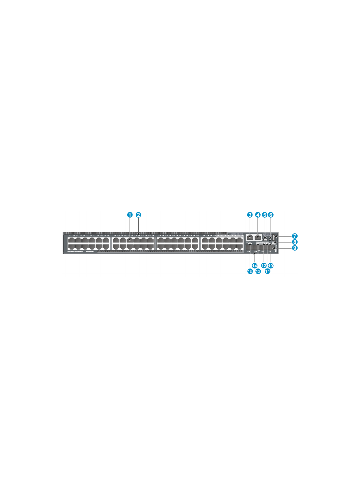
1. Product overview
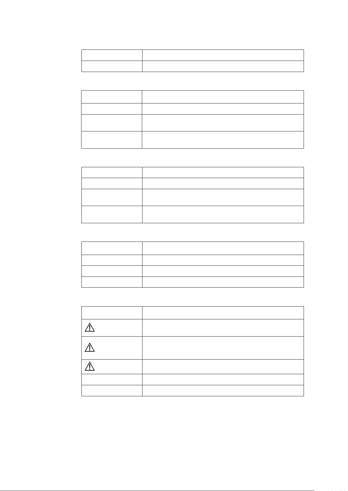
(1) 10/100/1000 BASE-T autosensing Ethernet port
(2) 10/100/1000 BASE-T autosensing Ethernet port LED
(3) SFP+ port
(4) Console port
(5) USB mini Console port
(6) Port LED mode switching button
(7) Port mode LED
(8) USB port
(9) System status LED (SYS)
(10) RPS status LED (RPS)
(11) SFP+ port LED
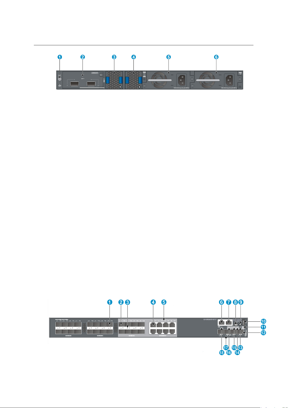
(1) QSFP+ port LED
(2) QSFP+ port
(3) AC-input power receptacle
(4) RPS receptacle
(5) Grounding screw
1. Product overview
1.1 QX-S5524GT-4X2Q panel views
Figure 1-1 QX-S5524GT-4X2Q front panel
Figure 1-2 QX-S5524GT-4X2Q rear panel
1-1
Page 10
Installation Guide
QX-S5500G Series Ethernet Switches
1. Product overview
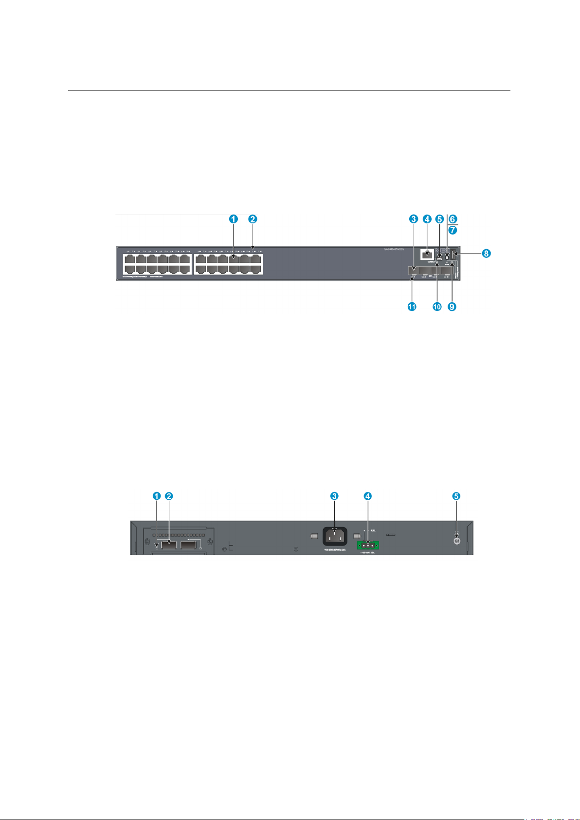
(1) 10/100/1000 BASE-T autosensing Ethernet port
(2) 10/100/1000 BASE-T autosensing Ethernet port LED
(3) SFP+ port
(4) Console port
(5) USB mini Console port
(6) Port LED mode switching button
(7) Port mode LED
(8) USB port
(9) System status LED (SYS)
(10) RPS status LED (RPS)
(11) SFP+ port LED
(1) QSFP+ port LED
(2) QSFP+ port
(3) AC-input power receptacle
(4) RPS receptacle
(5) Grounding screw
1.2 QX-S5548GT-4X2Q panel views
Figure 1-3 QX-S5548GT-4X2Q front panel
Figure 1-4 QX-S5548GT-4X2Q rear panel
1-2
Page 11
Installation Guide
QX-S5500G Series Ethernet Switches
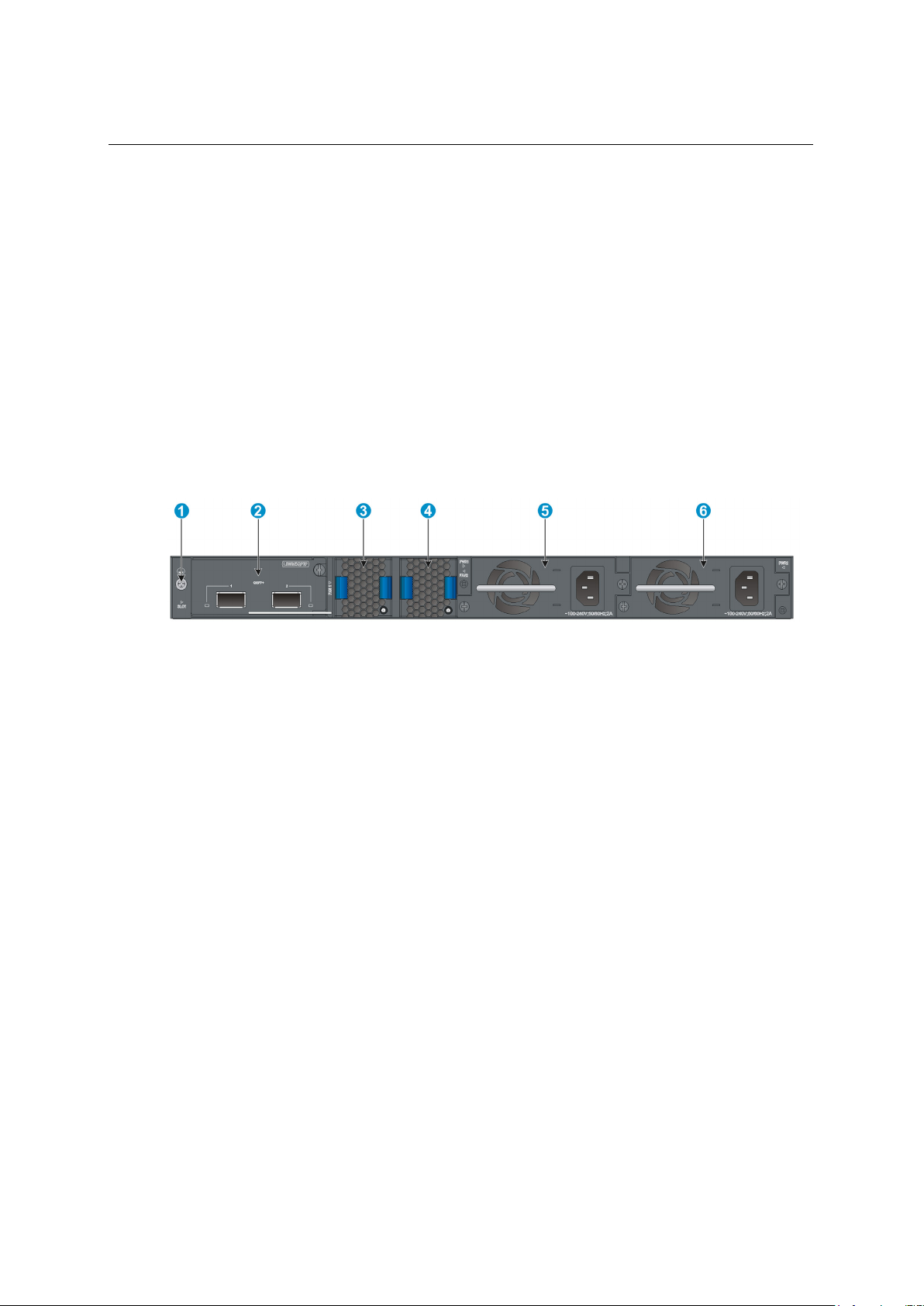
1. Product overview
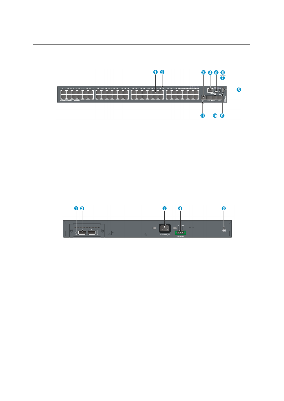
(1) 10/100/1000 BASE-T autosensing Ethernet port
(2) 10/100/1000 BASE-T autosensing Ethernet port LED
(3) Management Ethernet port
(4) Console port
(5) USB mini Console port
(6) Port LED mode switching button
(7) USB port
(8) System status LED (SYS)
(9) SFP+ port
(10) Port mode LED
(11) Interface card status LED (SLOT)
(12) Power module 2 status LED (PWR2)
(13) Power module 1 status LED (PWR1)
(14) SFP+ port LED
(15) Management Ethernet port LED
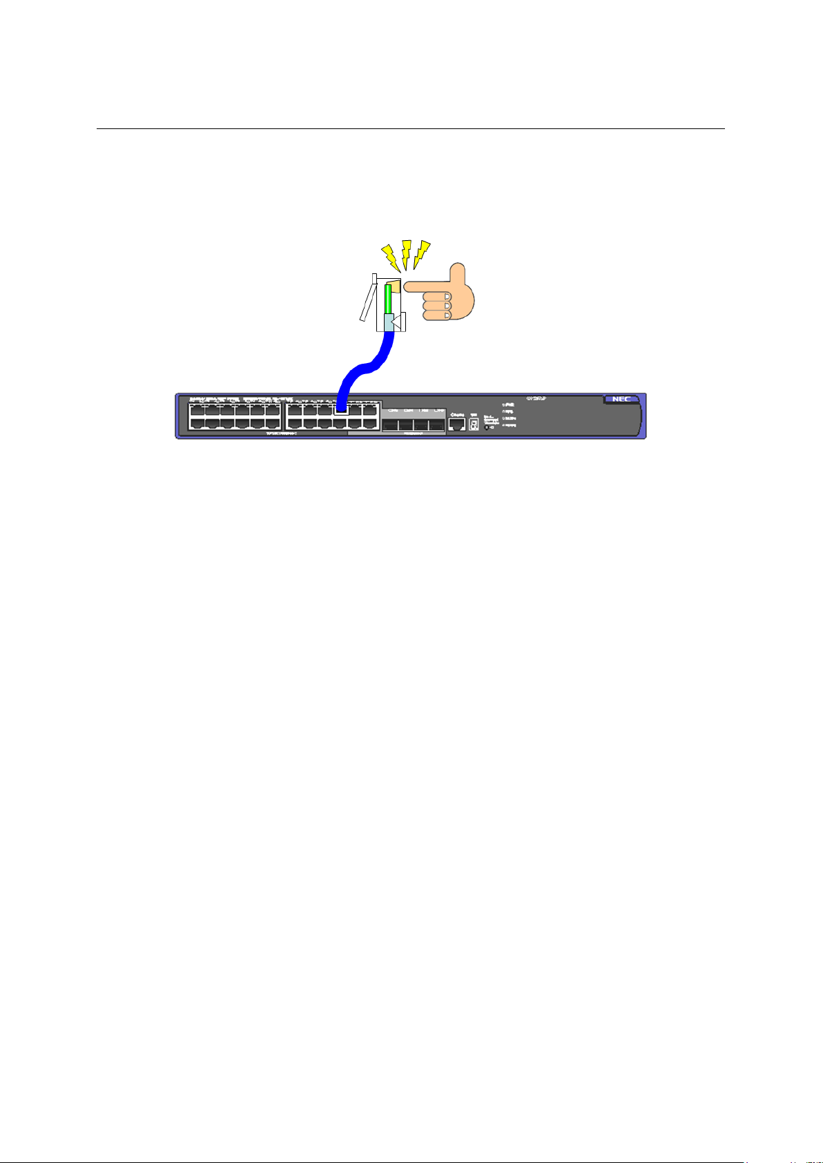
(1) Grounding screw
(2) Interface card slot
(3) Fan tray slot1
(4) Fan tray slot2
(5) Power module slot1
(6)Power module slot2
1.3 QX-S5524GT-4X1C panel views
Figure 1-5 QX-S5524GT-4X1C front panel
Figure 1-6 QX-S5524GT-4X1C rear panel
The QX-S5524GT-4X1C switch comes with power module slot 1 empty and power module
slot 2 installed with a filler panel. You can install one or two power modules for the switch as
required. In this figure, two PSR150-A1 AC power modules are installed in the power
module slots. For more information about installing and removing a power module, see
1-3
Page 12
Installation Guide
QX-S5500G Series Ethernet Switches
1. Product overview
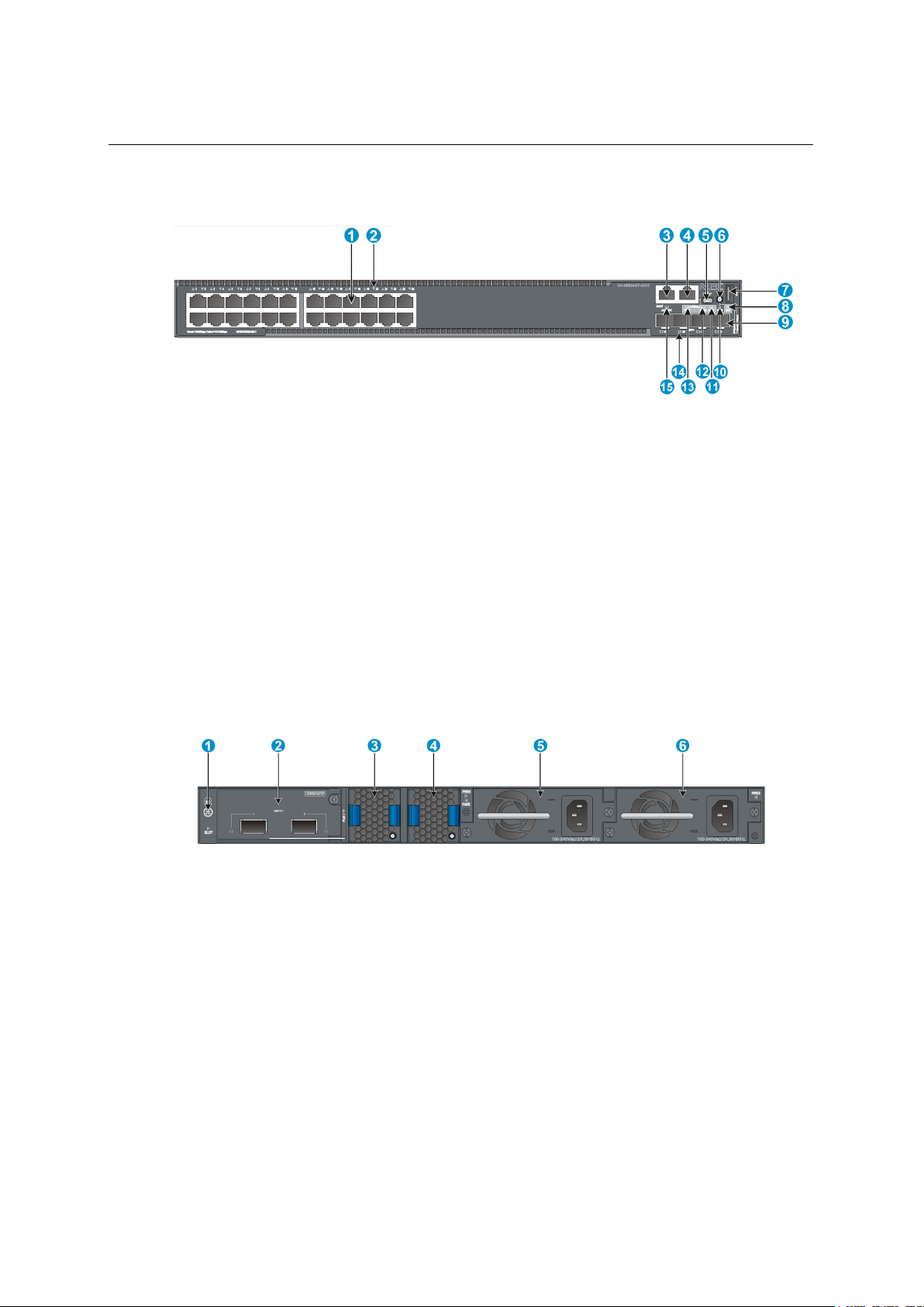
(1) 10/100/1000 BASE-T autosensing Ethernet port
(2) 10/100/1000 BASE-T autosensing Ethernet port LED
(3) Management Ethernet port
(4) Console port
(5) USB mini Console port
(6) Port LED mode switching button
(7) USB port
(8) System status LED (SYS)
(9) SFP+ port
(10) Port mode LED
(11) Interface card status LED (SLOT)
(12) Power module 2 status LED (PWR2)
(13) Power module 1 status LED (PWR1)
(14) SFP+ port LED
(15) Management Ethernet port LED
"Installing/removing a power module."
The QX-S5524GT-4X1C switch comes with the two fan tray slots empty. You must install
two fan trays of the same model for the switch. In this figure, two LSPM5FANSA fan trays
are installed in the fan tray slots. For more information about installing and removing a fan
tray, see "Installing/removing a fan tray."
The QX-S5524GT-4X1C switch comes with a filler panel in the interface card slot. You can
select an interface card for the switch as required. In this figure, an LSWM5QP2P interface
card is installed in the interface card slot. For more information about installing and
removing an interface card, see "Installing/removing an interface card."
1.4 QX-S5548GT-4X1C panel views
Figure 1-7 QX-S5548GT-4X1C front panel
1-4
Page 13
Installation Guide
QX-S5500G Series Ethernet Switches
1. Product overview
(1) Grounding screw
(2) Interface card slot
(3) Fan tray slot1
(4) Fan tray slot2
(5) Power module slot1
(6) Power module slot2
The QX-S5548GT-4X1C switch comes with power module slot 1 empty and power module
slot 2 installed with a filler panel. You can install one or two power modules for the switch as
required. In this figure, two PSR150-A1 AC power modules are installed in the power
module slots. For more information about installing and removing a power module, see
Figure 1-8 QX-S5548GT-4X1C rear panel
"Installing/removing a power module."
The QX-S5548GT-4X1C switch comes with the two fan tray slots empty. You must install
two fan trays of the same model for the switch. In this figure, two LSPM5FANSA fan trays
are installed in the fan tray slots. For more information about installing and removing a fan
tray, see "Installing/removing a fan tray."
The QX-S5548GT-4X1C switch comes with a filler panel in the interface card slot. You can
select an interface card for the switch as required. In this figure, an LSWM5QP2P interface
card is installed in the interface card slot. For more information about installing and
removing an interface card, see "Installing/removing an interface card."
1.5 QX-S5524GP-4X1C panel views
Figure 1-9 QX-S5524GP-4X1C front panel
1-5
Page 14
Installation Guide
QX-S5500G Series Ethernet Switches
1. Product overview
(1) SFP port
(2) SFP port (Combo port, port 17S to 24S)
(Combo port, port 17T to 24T)
(5) 10/100/1000 BASE-T autosensing Ethernet port LED
(6) Management Ethernet port
(7) Console port
(8) USB mini Console port
(9) Port LED mode switching button
(10) USB port
(11) System status LED (SYS)
(12) SFP+ port
(13) Port mode LED
(14) Interface card status LED (SLOT)
(15) Power module 2 status LED (PWR2)
(16) Power module 1 status LED (PWR1)
(17) SFP+ port LED
(18) Management Ethernet port LED
(1) Grounding screw
(2) Interface card slot
(3) Fan tray slot1
(4) Fan tray slot2
(5) Power module slot1
(6) Power module slot2
(3) SFP port LED (4) 10/100/1000 BASE-T autosensing Ethernet port
Figure 1-10 QX-S5524GP-4X1C rear panel
The QX-S5524GP-4X1C switch comes with power module slot 1 empty and power module
slot 2 installed with a filler panel. You can install one or two power modules for the switch as
required. In this figure, two PSR150-A1 AC power modules are installed in the power
module slots. For more information about installing and removing a power module, see
"Installing/removing a power module."
The QX-S5524GP-4X1C switch comes with the two fan tray slots empty. You must install
two fan trays of the same model for the switch. In this figure, two LSPM5FANSA fan trays
are installed in the fan tray slots. For more information about installing and removing a fan
tray, see "Installing/removing a fan tray."
The QX-S5524GP-4X1C switch comes with a filler panel in the interface card slot. You can
select an interface card for the switch as required. In this figure, an LSWM5QP2P interface
card is installed in the interface card slot. For more information about installing and
1-6
Page 15

Installation Guide
QX-S5500G Series Ethernet Switches
1. Product overview
removing an interface card, see "Installing/removing an interface card."
1-7
Page 16

Installation Guide
QX-S5500G Series Ethernet Switches
Contents
Contents
2. Preparing for installation .......................................................................................................... 2-1
2.1 Safety recommendations ................................................................................................... 2-1
2.2 Connecting the RJ45 connector ........................................................................................ 2-1
2.3 Examining the installation site ........................................................................................... 2-2
2.3.1 Temperature/humidity ............................................................................................. 2-2
2.3.2 Cleanness ............................................................................................................... 2-3
2.3.3 EMI .......................................................................................................................... 2-3
2.3.4 Laser safety ............................................................................................................. 2-3
2.4 Installation tools ................................................................................................................. 2-4
i
Page 17

Installation Guide
QX-S5500G Series Ethernet Switches
Preparing for installation
2. Preparing for installation
2.1 Safety recommendations
To avoid any equipment damage or bodily injury caused by improper use, read the
following safety recommendations before installation. Note that the recommendations do
not cover every possible hazardous condition.
Regarding with installation and maintenance of this product, please make the engineer who
acquired a right operating method to do that.
Remove dust on and around the Switch regularly.
Before cleaning the switch, unplug all power cords from the switch. Do not clean the
switch with wet cloth or liquid.
Before moving the Switch, unplug all power cords from the switch.
Do not place the switch near water or in a damp environment. Prevent water or
moisture from entering the switch chassis.
Do not place the switch on an unstable case or desk. The switch might be severely
damaged in case of a fall.
Ensure proper ventilation of the equipment room and keep the air inlet and outlet vents
of the switch free of obstruction.
Connect the yellow-green protection grounding cable before power-on.
Make sure the operating voltage is in the required range.
Please don't open equipment. Breakdowns when opening, will be applying of the
guarantee.
When replacing FRUs, including power modules and fan trays, wear an
ESD-preventive wrist strap to avoid damaging the units.
Please be sure to do service operation of the equipment which is being used after a
power supply is off.
Please put dustproof cover on the port where SFP/SFP+/QSFP+ transceiver module
isn't mounted.
2.
2.2 Connecting the RJ45 connector
NOTE:
When connecting the RJ45 cable, wear a wrist strap to protect against static electricity.
Do not touch the RJ45 Ethernet cable terminal. If you touch the RJ45 Ethernet cable
terminal which is connecting to the Switch, the interface circuit may be broken by the static
electricity. When you connect the Console cable, you need also a same care.
2-1
Page 18
Installation Guide
QX-S5500G Series Ethernet Switches
Preparing for installation
Figure 2-1 Connecting the RJ45 connector
2.3 Examining the installation site
2.
The QX-S5500G Series switches must be used indoors.
You can mount your switch in a rack, or on a workbench, and make sure:
Adequate clearance is reserved at the air inlet and exhaust vents for ventilation.
The rack, or on the workbench have a good ventilation system.
Identify the hot aisle and cold aisle at the installation site, and make sure ambient air
flows into the switch from the cold aisle and exhausts to the hot aisle.
Identify the airflow designs of neighboring devices, and prevent hot air flowing out of
the bottom device from entering the top device.
The rack, or the workbench are sturdy enough to support the switch and its
accessories.
The rack is well earthed.
To ensure normal operation and long service life of your switch, install it in an environment
that meets the requirements described in the following subsections.
2.3.1 Temperature/humidity
Maintain appropriate temperature and humidity in the equipment room.
Lasting high relative humidity can cause poor insulation, electricity creepage,
mechanical property change of materials, and metal corrosion.
Lasting low relative humidity can cause washer contraction and ESD and bring
problems including loose captive screws and circuit failure.
High temperature can accelerate the aging of insulation materials and significantly
lower the reliability and lifespan of the switch.
For the temperature and humidity requirements of different switch models, see "Technical
specifications" of “Chapter 1 Product overview”.
2-2
Page 19
Installation Guide
QX-S5500G Series Ethernet Switches
Preparing for installation
Dust ≤ 3 x 10⁴ (no visible dust on the tabletop over three days)
Note:
Dust diameter ≥ 5 μm
SO
2
0.2
H2S
0.006
NH3
0.05
Cl2
0.01
2.3.2 Cleanness
Dust buildup on the chassis may result in electrostatic adsorption, which causes poor
contact of metal components and contact points, especially when indoor relative humidity is
low. In the worst case, electrostatic adsorption can cause communication failure.
The equipment room must also meet strict limits on salts, acids, and sulfides to eliminate
corrosion and premature aging of components, as shown in Table 2-2
2.
Table 2-1 Dust concentration limit in the equipment room
Substance Concentration limit (particles/m³)
Table 2-2 Harmful gas limits in the equipment room
Gas Maximum concentration (mg/m3)
2.3.3 EMI
All electromagnetic interference (EMI) sources, from outside or inside of the switch and
application system, adversely affect the switch in a conduction pattern of capacitance
coupling, inductance coupling, electromagnetic wave radiation, or common impedance
(including the grounding system) coupling. To prevent EMI, take the following actions:
Please take the effective measures to reduce the intervention the power supply
system exerts on the switch.
Keep the switch far away from high-power radio launchers, radars, and equipment
with high frequency or high current.
If AC power is used, use a single-phase three-wire power receptacle with protection
earth (PE) to filter interference from the power grid.
Keep the switch far away from radio transmitting stations, radar stations, and
high-frequency devices.
Use electromagnetic shielding, for example, shielded interface cables, when
necessary.
Route interface cables only indoors to prevent signal ports from getting damaged by
overvoltage or overcurrent caused by lightning strikes.
2.3.4 Laser safety
The QX-S5500G Series switches are Class 1 laser devices.
2-3
Page 20

Installation Guide
QX-S5500G Series Ethernet Switches
Preparing for installation
WARNING:
Do not stare into any fiber port when the switch has power. The laser light emitted from the optical fiber may
hurt your eyes.
2.4 Installation tools
Phillips screwdriver
Flat-blade screwdriver
ESD-preventive wrist strap
NOTE:
All these installation tools have to be prepared by a user.
2.
2-4
Page 21

Installation Guide
QX-S5500G Series Ethernet Switches
Contents
Contents
3. Installing the switch .................................................................................................................. 3-1
3.1 Installation flow .................................................................................................................. 3-1
3.2 Installing the switch in a 19-inch rack ................................................................................ 3-3
3.2.1 Mounting bracket kits .............................................................................................. 3-3
3.2.2 Rack-mounting by using front mounting brackets ................................................... 3-3
3.2.3 Mount the chassis in the rack .................................................................................. 3-5
3.3 Mounting the switch on a workbench ................................................................................. 3-7
3.4 Grounding the switch ......................................................................................................... 3-7
3.4.1 Grounding the switch with a grounding strip ........................................................... 3-8
3.4.2 Connecting the rear grounding point to a grounding strip ....................................... 3-9
3.4.3 Grounding the switch with a grounding conductor buried in the earth ground...... 3-10
3.4.4 Grounding the switch by using the AC power cord ............................................... 3-11
3.5 Installing/removing a fan tray ........................................................................................... 3-13
3.5.1 Installing a fan tray ................................................................................................ 3-13
3.5.2 Removing a fan tray .............................................................................................. 3-14
3.6 Installing/removing a power module ................................................................................ 3-15
3.6.1 Installing a power module ..................................................................................... 3-16
3.6.2 Removing a power module ................................................................................... 3-18
3.7 Connecting the power cord .............................................................................................. 3-18
3.7.1 Connecting a AC power cord to the switch ........................................................... 3-19
3.7.2 Connecting a DC power cord to the switch ........................................................... 3-20
3.7.3 Connecting a AC power cord to the PSR150-A1 .................................................. 3-21
3.7.4 Connecting a DC power cord to the PSR150-D1 .................................................. 3-22
3.7.5 Making of DC power cord ...................................................................................... 3-23
3.8 Installing/removing an interface card ............................................................................... 3-26
3.8.1 Installing an interface card .................................................................................... 3-26
3.8.2 Removing an interface card .................................................................................. 3-29
3.9 Installing/Removing a SFP/SFP+/QSFP+ transceiver module ........................................ 3-29
3.9.1 Installing a SFP/SFP+/QSFP+ transceiver module .............................................. 3-30
3.9.2 Removing a SFP/SFP+/QSFP+ transceiver module ............................................ 3-30
3.10 Connecting an interface cable ....................................................................................... 3-31
3.10.1 Connecting a UTP cable ..................................................................................... 3-31
i
Page 22

Installation Guide
QX-S5500G Series Ethernet Switches
Contents
3.10.2 Connecting a fiber optic-cable ............................................................................. 3-31
3.11 Verifying the installation ................................................................................................. 3-32
ii
Page 23

Installation Guide
QX-S5500G Series Ethernet Switches
3. Installing the switch
3. Installing the switch
CAUTION:
Keep the tamper-proof seal on a mounting screw on the chassis cover intact. If you tear off the tamper-proof
seal, switch shall not be guarantee applying. If you tear off the tamper-proof seal and open the chassis, NEC
shall not be liable for any consequence caused thereby.
NOTE:
The description of an installation procedure of device is indicated on this chapter , but please refer to a product
for the outward appearance of the actual equipment .
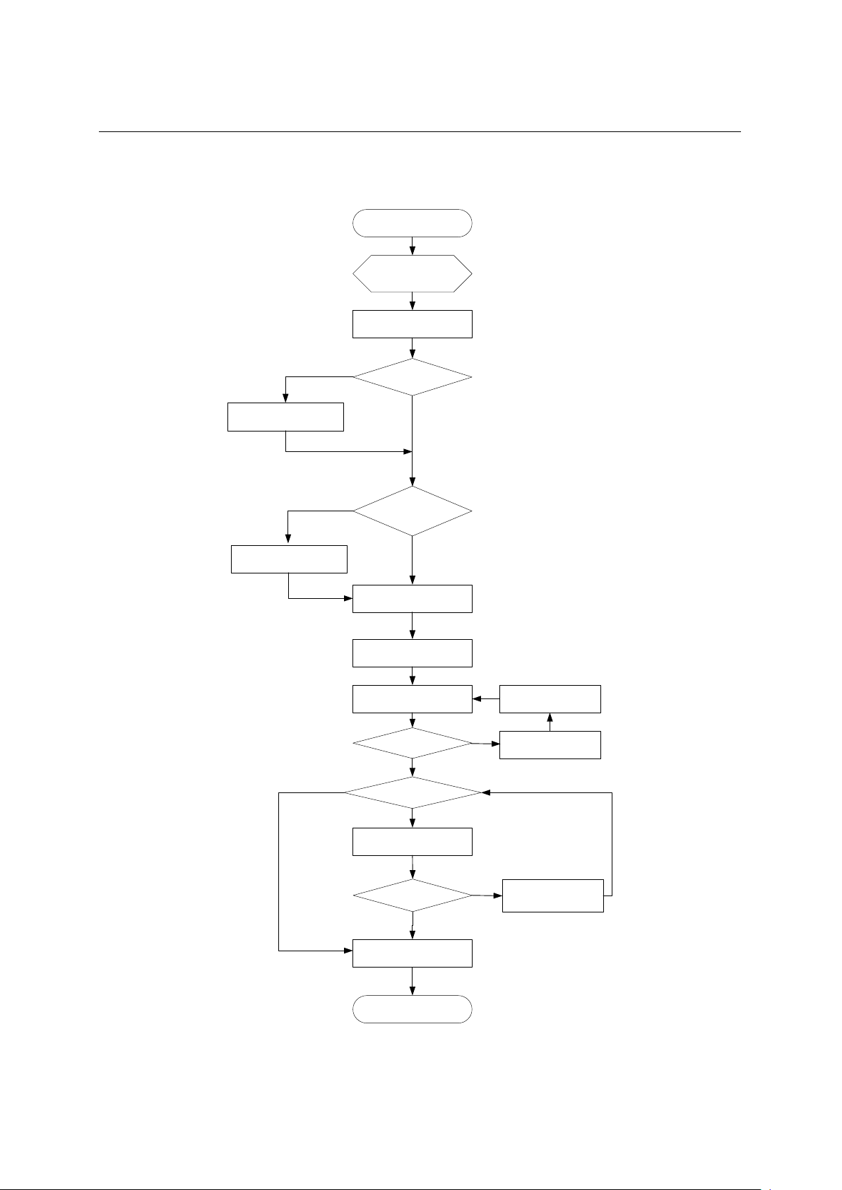
3.1 Installation flow
3-1
Page 24
Installation Guide
QX-S5500G Series Ethernet Switches
3. Installing the switch
Ground the switch
Install the switch
Start
Connect power cords
Verify the installation
Power on the switch
Select and install power
modules
Hot-swap power
modules?
Yes
No
Operating correctly?
Power off the switch
Troubleshoot the switch
No
Yes
Hot-swap cards?
Install interface cards
Yes
Troubleshoot the switch
Yes
No
End
No
Hot-swap
fan trays?
Select and install fan trays
Yes
No
Operating correctly?
Install transceiver modules
and cables
Figure 3-1 Hardware installation flow
3-2
Page 25
Installation Guide
QX-S5500G Series Ethernet Switches
3. Installing the switch
L1
L2
1
2
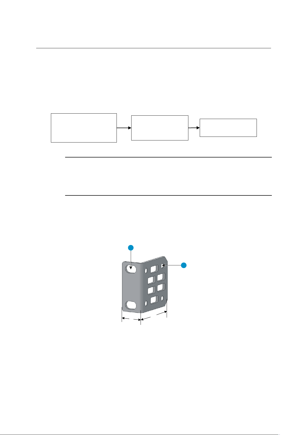
(1) Hole for attaching the bracket to a
rack
(2) Hole for attaching the bracket to the
switch chassis
Attach the front
Mount the switch in the
Identify the mounting
3.2 Installing the switch in a 19-inch rack
The mounting bracket kit can be installed on the port side, power module side, or the
middle bracket installation position. Attach on the appropriate location with an actual
necessary condition .
Figure 3-2 Rack-mounting procedure
position ( port side, the
power side, or middle
position ) for the mounting
brackets
NOTE:
If a rack shelf is available, you can put the switch on the rack shelf, slide the switch to an appropriate location,
and attach the switch to the rack by using the mounting brackets.
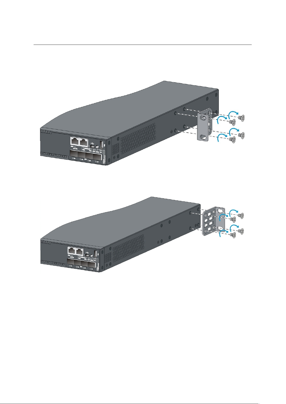
3.2.1 Mounting bracket kits
mounting brackets to the
two sides of the switch
Figure 3-3 Front mounting bracket kit
rack
3.2.2 Rack-mounting by using front mounting brackets
To install the switch in a 19-inch rack by using the front mounting brackets:
3-3
Page 26
Installation Guide
QX-S5500G Series Ethernet Switches
3. Installing the switch
Identify the mounting positions.
1) Wear an ESD wrist strap and make sure it makes good skin contact and is correctly
2) Attach the front mounting brackets to the chassis:
3) Unpack the front mounting brackets and the M4 screws (supplied with the switch) for
4) Align the round holes in the wide flange of one front mounting bracket with the screw
5) Use M4 screws to attach the mounting bracket to the chassis.
6) Repeat the proceeding two steps to attach the other mounting bracket to the chassis.
grounded.
attaching the brackets to the switch chassis.
holes in the chassis. The bracket mounting positions is Port side, power module side,
or middle installation position.
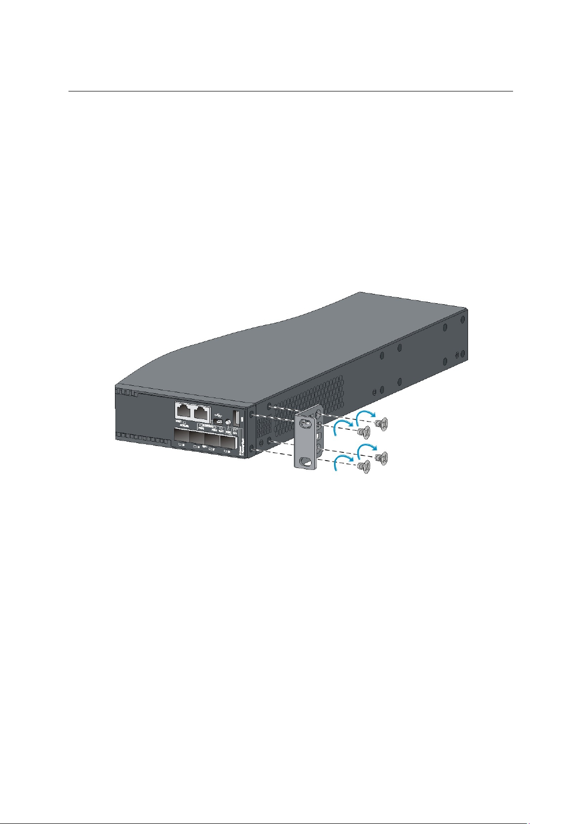
Figure 3-4 Attaching the front mounting bracket to the port side
3-4
Page 27
Installation Guide
QX-S5500G Series Ethernet Switches
3. Installing the switch
Figure 3-5 Attaching the front mounting bracket to the middle installation position
Figure 3-6 Attaching the front mounting bracket to the power module side
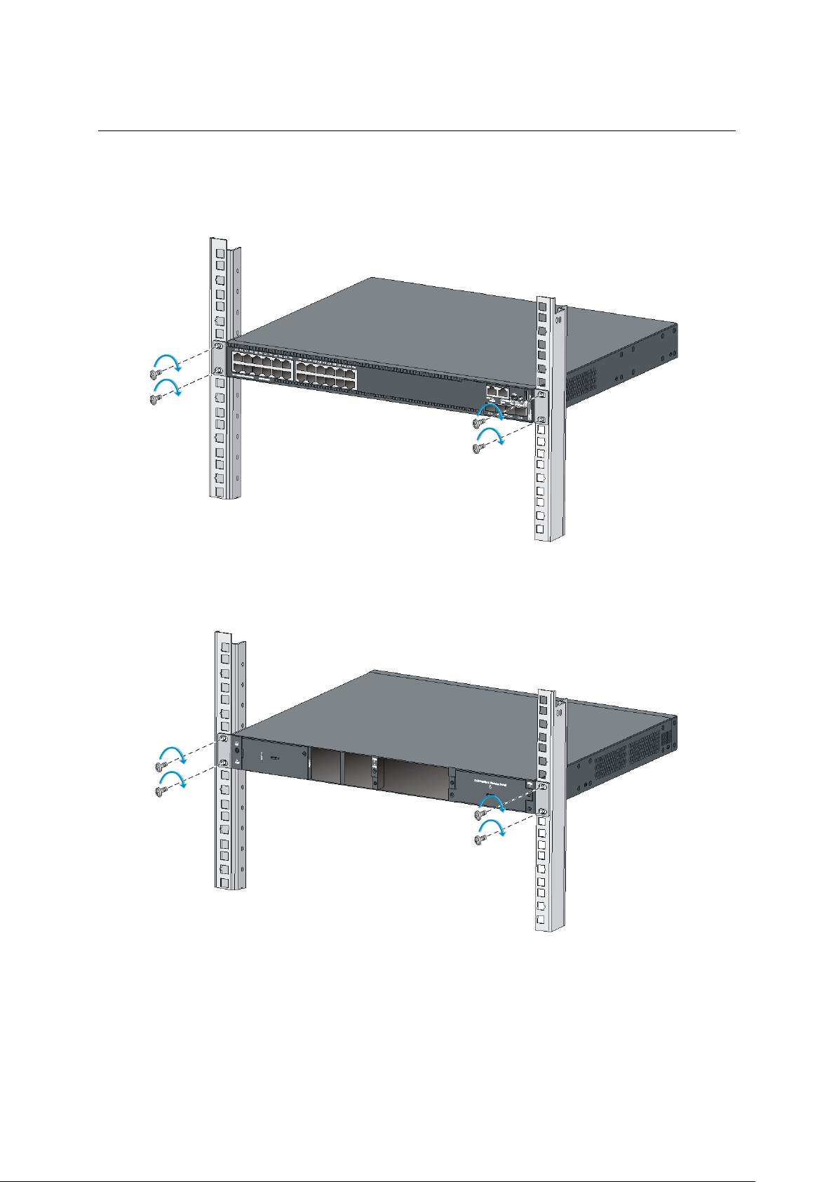
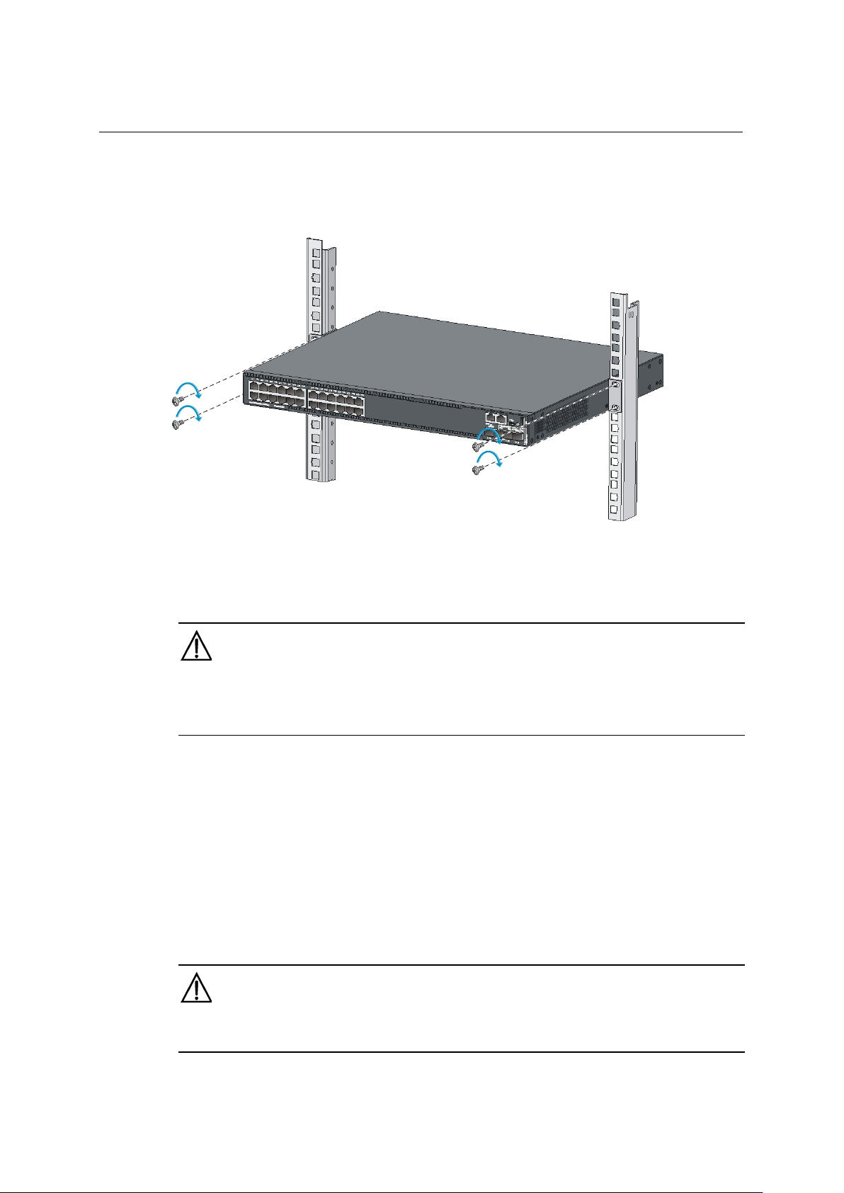
3.2.3 Mount the chassis in the rack
This task requires two people.
1) One person supports the chassis bottom with one hand, holds the front part of the
chassis with the other hand, and pushes the chassis into the rack gently
2) The other person uses M6 screws and cage nuts (user supplied) to attach the switch
to the rack. Prepare the cage nuts and the screws yourself.
3-5
Page 28
Installation Guide
QX-S5500G Series Ethernet Switches
3. Installing the switch
Figure 3-7 け Mounting the switch in the rack (front mounting brackets at the port side)
Figure 3-8 Mounting the switch in the rack (front mounting brackets at the power module side)
3-6
Page 29
Installation Guide
QX-S5500G Series Ethernet Switches
3. Installing the switch
Figure 3-9 Mounting the switch in the rack (front mounting brackets at the middle installation position)
3.3 Mounting the switch on a workbench
IMPORTANT:
Ensure good ventilation and 10 cm (3.9 in) of clearance around the chassis for heat dissipation.
Avoid placing heavy objects on the switch.
To mount the switch on a workbench:
1) Verify that the workbench is sturdy and correctly grounded.
2) Place the switch with bottom up, and clean the round holes in the chassis bottom with
dry cloth.
3) Attach the rubber feet to the four round holes in the chassis bottom.
4) Place the switch with upside up on the workbench.
3.4 Grounding the switch
WARNING:
Correctly connecting the switch grounding cable is crucial to lightning protection and EMI protection.
3-7
Page 30
Installation Guide
QX-S5500G Series Ethernet Switches
3. Installing the switch
The power input end of the switch has a noise filter, whose central ground is directly
connected to the chassis to form the chassis ground (commonly known as PGND). You
must securely connect this chassis ground to the earth so the faradism and leakage
electricity can be safely released to the earth to minimize EMI susceptibility of the switch.
You can ground the switch in one of the following ways, depending on the grounding
conditions available at the installation site:
Grounding the switch with a grounding strip
Grounding the switch with a grounding conductor buried in the earth ground
Grounding the switch by using the AC power cord
NOTE:
The power and grounding terminals in this section are for illustration only.
3.4.1 Grounding the switch with a grounding strip
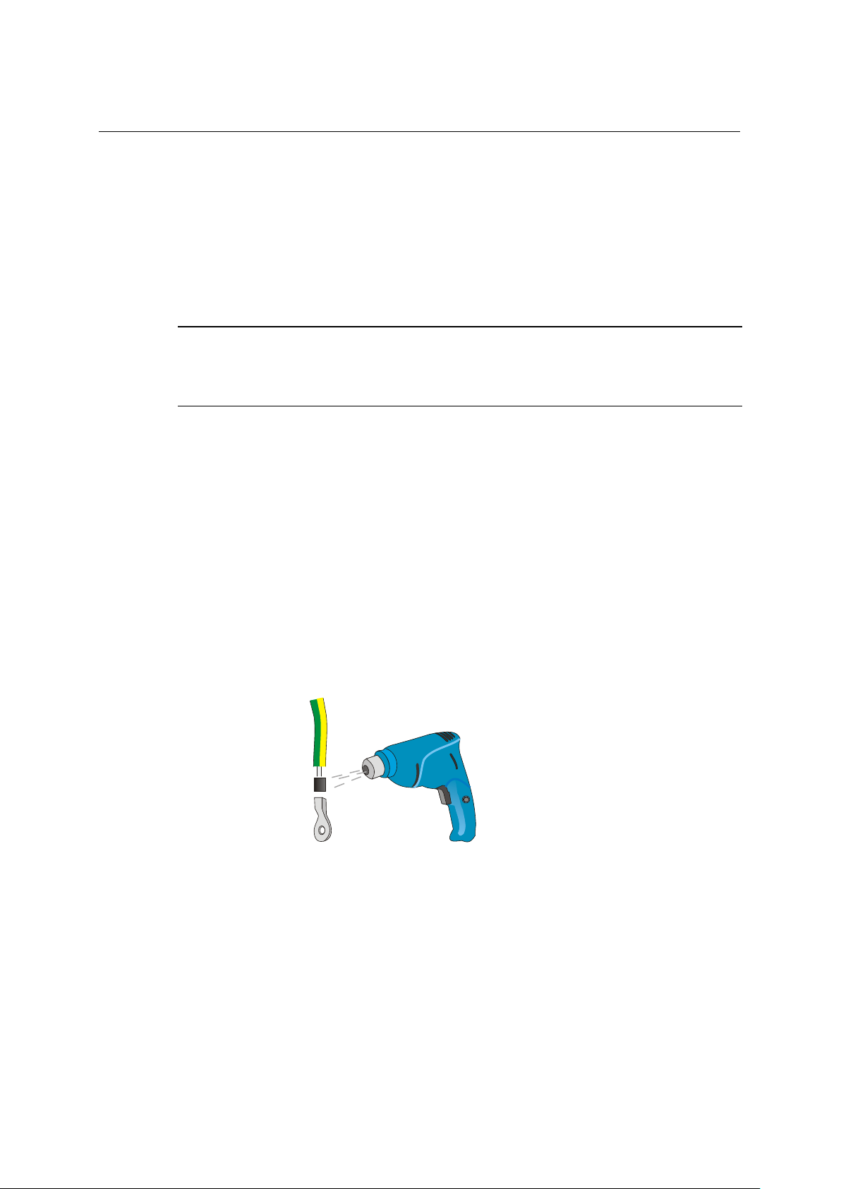
If a grounding strip is available at the installation site, connect the grounding cable to the
grounding strip.
1) Cut the grounding cable as appropriate for connecting to the grounding strip.
2) Peel 5 mm (0.20 in) of insulation sheath by using a wire stripper, and insert the bare
metal part through the black insulation covering into the end of the ring terminal
supplied with the switch.
3) Secure the metal part of the cable to the ring terminal with a crimper, cover the joint
with the insulation covering, and heat the insulation covering with a blow dryer to
completely cover the metal part.
Figure 3-10 Attaching a ring terminal to the grounding cable
3-8
Page 31

Installation Guide
QX-S5500G Series Ethernet Switches
3. Installing the switch
(1) Grounding cable
(2) Grounding sign
(3) Grounding hole
(4) Ring terminal
(5) Grounding screw
3.4.2 Connecting the rear grounding point to a grounding strip
WARNING:
Connect the grounding cable to the grounding system in the equipment room. Do not connect it to a fire main or
lightning rod.
Connecting the rear grounding point to a grounding strip:
1) Remove the grounding screw from the rear panel of the switch chassis.
2) Use the grounding screw to attach the ring terminal of the grounding cable to the
grounding screw hole.
Figure 3-11 Connecting the grounding cable to the chassis
IMPORTANT:
Orient the grounding cable as shown in Figure 3-11 so you can easily install or remove interface card.
3) Verify that the grounding cable has been securely connected to the rear grounding
point.
4) Remove the hex nut of a grounding post on the grounding strip.
5) Cut the grounding cable as appropriate for connecting to the grounding strip.
3-9
Page 32

Installation Guide
QX-S5500G Series Ethernet Switches
3. Installing the switch
1
4
3
2
(1) Grounding post
(2) Grounding strip
(3) Grounding cable
(4) Hex nut
Figure 3-12 Connecting the grounding cable to a grounding strip
3.4.3 Grounding the switch with a grounding conductor buried in the earth ground
If the installation site has no grounding strips, but earth ground is available, hammer a 0.5
m (1.64 ft.) or longer angle iron or steel tube into the earth ground to serve as a grounding
conductor.
The dimensions of the angle iron must be a minimum of 50 × 50 × 5 mm (1.97 × 1.97 × 0.20
in). The steel tube must be zinc-coated and its wall thickness must be a minimum of 3.5 mm
(0.14 in).
Weld the yellow-green grounding cable to the angel iron or steel tube and treat the joint for
corrosion protection.
3-10
Page 33

Installation Guide
QX-S5500G Series Ethernet Switches
3. Installing the switch
1
2
3
4
5
6
(1) Grounding screw
(2) Chassis rear panel
(3) Grounding cable
(4) Earth
(5) Joint
(6) Grounding conductor
Figure 3-13 Grounding the switch by burying the grounding conductor into the earth ground
3.4.4 Grounding the switch by using the AC power cord
If the installation site has no grounding strips or earth ground, you ground an AC-powered
switch through the PE wire of the power cord. Make sure:
The power cord has a PE terminal.
The ground contact in the power outlet is securely connected to the ground in the
power distribution room or on the AC transformer side.
The power cord is securely connected to the power outlet.
NOTE:
If the ground contact in the power outlet is not connected to the ground, report the problem and reconstruct the
grounding system.
3-11
Page 34

Installation Guide
QX-S5500G Series Ethernet Switches
3. Installing the switch
(1) Three-wire AC power cord
(2) Chassis rear panel
Figure 3-14 Grounding through the PE wire of the AC power cord
NOTE:
To guarantee the grounding effect, use the grounding cable provided with the switch to connect to the
grounding strip in the equipment room as long as possible.
3-12
Page 35

Installation Guide
QX-S5500G Series Ethernet Switches
3. Installing the switch
3.5 Installing/removing a fan tray
CAUTION:
Install two fan trays of the same model on the switch. Do not power on the switch when it does not have fan
trays or has only one fan tray installed.
Make sure slots are installed with fan trays or blank filler panels for the device to operate.
At the first login to the QX-S5524GT-4X1C, QX-S5548GT-4X1C or QX-S5524GP-4X1C, use the fan
prefer-direction command to set the airflow direction of the switch to be the same as the airflow direction
of the fan tray. If the fan tray has a different airflow direction than the switch, the system outputs traps and
logs to notify you to replace the fan tray.
By default, the switch uses the same airflow direction (power-to-port) as the LSPM5FANSA fan tray.
If both fan trays fail during operation, replace them immediately. One fan trays don't make switch move,
please while breaking down.
Please don't remove a broken fan module until exchange preparations of a fan trays can be done.
If fan trays fail during operation, replace them within 2 minutes while the switch is operating. Please don't
make switch move in the state which has no fan trays for more than 2 minutes.
Failure to comply with these operating requirements may void the warranty.
The QX-S5524GT-4X1C, QX-S5548GT-4X1C or QX-S5524GP-4X1C switches support
hot-swappable fan trays.
The switch comes with empty fan tray slots. Choose the fan tray models based on the
ventilation requirement of the site. The air flow direction varies by fan tray model.
The LSPM5FANSA has a blue handle and provides power-to-port air flow.
The LSPM5FANSB has a red handle and provides port-to-power air flow.
3.5.1 Installing a fan tray
CAUTION:
To prevent damage to the fan tray or the connectors on the backplane, insert the fan tray gently. If you
encounter a hard resistance while inserting the fan tray, pull out the fan tray and insert it again.
To install a fan tray:
1) Wear an ESD wrist strap and make sure it makes good skin contact and is correctly
grounded.
2) Unpack the fan tray and verify that the fan tray model is correct.
3-13
Page 36

Installation Guide
QX-S5500G Series Ethernet Switches
3. Installing the switch
3) Grasp the two handles of the fan tray with the side marked TOP facing up, and slide
the fan tray along the guide rails into the slot until the fan tray seats in the slot and has
a firm contact with the backplane.
Figure 3-15 Installing a fan tray
3.5.2 Removing a fan tray
WARNING:
Do not touch conductors or terminals on the fan trays.
Do not place the fan tray in moist place. Prevent liquid from entering the fan tray.
Fan trays with faulty internal wiring and conductors require maintenance from maintenance engineers. Do
not disassemble the faulty fan trays.
To remove a fan tray:
1) Wear an ESD wrist strap and make sure it makes good skin contact and is correctly
grounded.
2) Grasp the two handles of the fan tray, as shown by callout 1 in Figure 3-16, and pull
out the fan tray slowly along the guide rails.
3) Put the removed fan tray in an antistatic bag.
3-14
Page 37

Installation Guide
QX-S5500G Series Ethernet Switches
3. Installing the switch
Install the power
module
Connect the power
cord
Turn on the circuit
breaker
Figure 3-16 Removing a fan tray
3.6 Installing/removing a power module
CAUTION:
Provide a circuit breaker for each power module.
There is power supply module slot 2 on which power supply module slot 1 in the empty and
a blank panel were mounted with two power supply module slots for the
QX-S5524GT-4X1C, QX-S5548GT-4X1C or QX-S5524GP-4X1C. You can install one or
two power modules for the switch as needed. For more information about effective power
supply module, see "Appendix B FRUs and compatibility matrixes”
In power redundancy mode, you can replace a power module without powering off the
switch but you must strictly follow the installation and procedures in Figure 3-17 and Figure
3-18 to avoid any bodily injury or damage to the switch.
Figure 3-17 Installation procedure
3-15
Page 38

Installation Guide
QX-S5500G Series Ethernet Switches
3. Installing the switch
Turn off the circuit
breaker
Disconnect the power
cord
Remove the power
module
These procedures are common by PSR150-A1 and PSR150-D1. It's explained taking
PSR150-A1 for instance at this chapter.
3.6.1 Installing a power module
To install a power module:
1) Wear an ESD wrist strap and make sure it makes good skin contact and is correctly
grounded.
2) Unpack the power module and verify that the power module model is correct.
3) Correctly orient the power module with the power module slot (use the letters on the
power module faceplate for orientation), grasp the handle of the power module with
one hand and support its bottom with the other, and slide the power module slowly
along the guide rails into the slot (see callout 1 in Figure 3-19).
To prevent damage to the power module or the connectors on the backplane, insert the
power module gently. If you encounter a hard resistance while inserting the power
module, pull out the power module and insert it again.
4) Fasten the captive screws on the power module with a Phillips screwdriver to secure
the power module in the chassis (see callout 2 in Figure 3-19).
If the captive screw cannot be tightly fastened, verify the installation of the power
module.
Figure 3-18 Removal procedure
3-16
Page 39

Installation Guide
QX-S5500G Series Ethernet Switches
3. Installing the switch
1
2
1
Figure 3-19 Installing a power module
NOTE:
If the power module slot where you want to install a power module is covered by a filler
panel, remove the filler panel first.
When necessary power supply module is one, please insert power supply module in
power supply module slot 1. Then insert a filler panel in power supply module slot 2.
Removing the filler panel:
Loosen the captive screws of the power module with a Phillips screwdriver until they
are completely disengaged.
Put a flat screwdriver in central prominence of a filler panel, please so as not to
damage. And remove a filler panel. Please keep a filler panel in the purpose when
using it next time.
Figure 3-20 Removing the filler panel
3-17
Page 40

Installation Guide
QX-S5500G Series Ethernet Switches
3. Installing the switch
QX-S5524GT-4X2Q
QX-S5548GT-4X2Q
AC power
Connecting an AC power cord to the switch
DC power
Connecting an DC power cord to the switch
QX-S5524GT-4X1C
QX-S5524GP-4X1C
PSR150-A1
AC power
Connecting an AC power cord to the PSR150-A1
3.6.2 Removing a power module
CAUTION:
When two of power supply module is mounted on switch, even if one of power supply module is removed, it
doesn't influence movement of switch. When only one of power supply module is mounted on equipment, when
power supply module is removed, a power supply of equipment becomes off.
To remove a power module:
1) Wear an ESD wrist strap and make sure it makes good skin contact and is correctly
grounded.
2) Disconnect the power cord.
3) Loosen the captive screws of the power module with a Phillips screwdriver until they
are completely disengaged.
4) Grasp the handle of the power module with one hand and pull it out a little, support the
bottom with the other hand, and pull the power module slowly along the guide rails out
of the slot.
5) Put away the removed power module in an antistatic bag or the power module
package bag for future use.
3.7 Connecting the power cord
Warning:
When fixing power cord on switch, please can cut a power supply of switch anytime in the state which reaches
a plug of power cord and an outlet right now.
Table 3-1 Tasks list
Switch
QX-S5548GT-4X1C
Power
module
-
PSR150-D1 DC power Connecting an DC power cord to the PSR150-D1
CAUTION:
The AC power cord isn't attached to switch. The AC power cord has to be prepared by
a user.
The socket-outlet shall be installed near the switch and shall be easily accessible.
Power
type
Connection procedure reference
3-18
Page 41

Installation Guide
QX-S5500G Series Ethernet Switches
3. Installing the switch
IEC-320-C13
IEC-320-C13
Connector(on the Device Side) Cable Ratings Cable Length Plug(Power Facility)
Figure 3-21 Power cord Specifications
125V, 10A
250V, 10A
Comply the standard of
each country
Comply the standard of
each country
Comply the standard of
each country
Comply the standard of
each country
The DC power cord isn't attached to switch. The DC power cord has to be prepared by a user. see “Making
of DC power cord”.
When using QX-PS800-T2, please prepare connected DC power cord to QX-PS800-T2. supplied DC
power cord is attached to QX-PS800-T2.
NOTE:
The power cord isn't attached to switch. The power cord has to be prepared by a user.
There is a possibility that a Power Cable Holder can't be used for a power cord, depending on the kind of
power cord.
3.7.1 Connecting a AC power cord to the switch
To connect an AC power cord to the QX-S5524GT-4X2Q or QX-S5548GT-4X2Q that uses
fixed power modules:
1) Wear an ESD wrist strap and make sure it makes good skin contact and is correctly
grounded.
2) Attach the hooks of the bail latch into the holes on the two sides of the AC-input power
receptacle, and pull the bail latch upwards (see Figure 3-22).
3) Connect one end of the AC power cord to the AC-input power receptacle on the switch
(see callout 1 in Figure 3-23).
4) Pull the bail latch down to secure the plug to the power receptacle (see callout 2 in
Figure 3-23).
5) Connect the other end of the power cord to the AC power outlet.
3-19
Page 42

Installation Guide
QX-S5500G Series Ethernet Switches
3. Installing the switch
1
2
Figure 3-22 Connecting an AC power cord to the switch (1)
Figure 3-23 Connecting an AC power cord to the switch (2)
3.7.2 Connecting a DC power cord to the switch
To connect a DC power cord to the switch:
1) Wear an ESD wrist strap and make sure it makes good skin contact and is correctly
grounded.
2) Correctly orient the plug at one end of the cable with the power receptacle on the
power module, and insert the plug into the power receptacle. See callout 1 in Figure
3-24.
3) If you cannot insert the plug into the receptacle, re-orient the plug rather than use
excessive force to push it in.
4) Tighten the screws on the plug with a flat-blade screwdriver to secure the plug in the
power receptacle. See callout 2 in Figure 3-24.
3-20
Page 43

Installation Guide
QX-S5500G Series Ethernet Switches
3. Installing the switch
2
1
5) Connect the two wires at the other end of the power cord to a –48 VDC power source
or QX-PS800-T2. Please classify two cord by a mark of (+) and (-) to stop a connection
mistake.
Figure 3-24 Connecting a DC power cord to the switch
3.7.3 Connecting a AC power cord to the PSR150-A1
To connect an AC power cord to the QX-S5524GT-4X1C, QX-S5548GT-4X1C, or
QX-S5524GP-4X1C use PSR150-A1 power supply module.
1) Wear an ESD wrist strap and make sure it makes good skin contact and is correctly
grounded.
2) Attach the hooks of the bail latch (supplied with the power module) into the two holes
next to the power receptacle on the power module, and pull the bail latch leftwards
(see Figure 3-25).
3) Connect one end of the AC power cord supplied with the power module to the power
receptacle (see callout 1 in Figure 3-26).
4) Pull the bail latch rightwards to secure the plug to the power receptacle (see callout 2
in Figure 3-26).
5) Connect the other end of the power cord to an AC power outlet.
3-21
Page 44

Installation Guide
QX-S5500G Series Ethernet Switches
3. Installing the switch
Figure 3-25 Connecting the PSR150-A1 (1)
Figure 3-26 Connecting the PSR150-A1 (2)
3.7.4 Connecting a DC power cord to the PSR150-D1
To connect an AC power cord to the QX-S5524GT-4X1C, QX-S5548GT-4X1C, or
QX-S5524GP-4X1C use PSR150-D1 power supply module.
1) Wear an ESD wrist strap and make sure it makes good skin contact and is correctly
grounded.
2) Unpack the DC power cord, correctly orient the plug at one end of the cable with the
power receptacle on the power module, and insert the plug into the power receptacle
(see callout 1 in Figure 3-27).
The power receptacle is foolproof. If you cannot insert the plug into the receptacle,
re-orient the plug rather than use excessive force to push it in.
3) Tighten the screws on the plug with a flat-blade screwdriver to secure the plug in the
power receptacle (see callout 2 in Figure 3-27).
4) Connect the two wires at the other end of the power cord to a –48 VDC power source.
3-22
Page 45

Installation Guide
QX-S5500G Series Ethernet Switches
3. Installing the switch
3.7.5 Making of DC power cord
Figure 3-27 Connecting the PSR150-D1
NOTE:
Please prepare the single line type for DC power cord.
The procedure which makes DC power cord is indicated below.
The DC power cord connector attached to switch consists of the following two parts. The
direction of the B of parts needs attention in particular.
After referring to Figure 3-28 and confirming the direction of the connector, please work so
that there are no connection mistakes.
3-23
Page 46

Installation Guide
QX-S5500G Series Ethernet Switches
3. Installing the switch
Figure 3-28 DC power cord connector supplied
Figure 3-29 Connectors B of parts
1) Please pass the DC power cord prepared into A of parts as shown in Figure 3-30.
3-24
Page 47

Installation Guide
QX-S5500G Series Ethernet Switches
3. Installing the switch
Figure 3-30 A of parts through DC power cord
2) A terminal for DC power cord is connected to B of parts. When connecting, please
connect so that it may correspond to a connector on the switch side. Please fix by the
screw which sticks to the upper part after connecting, so that a terminal doesn't come
off.
Figure 3-31 B of parts and connection of DC power cord
3) You combine B of parts with A of parts, tighten a screw and fix. There is a part where a
cable is fixed in A of parts. Please fix by tie-wrap (wire band) etc.
3-25
Page 48

Installation Guide
QX-S5500G Series Ethernet Switches
3. Installing the switch
Figure 3-32 DC power cord completion figure
3.8 Installing/removing an interface card
The QX-S5524GT-4X1C, QX-S5548GT-4X1C, or QX-S5524GP-4X1C each have one
expansion interface slot. It's possible to mount at most 1 expansion interface card as
needed. For the interface cards available for the switches, see "Appendix B FRUs and
compatibility matrixes."
CAUTION:
When an expansion interface card is inserted or it’s removed, don't touch joining terminal of a connector,
and please have a side.
To stop damage of an expansion interface card slot or a connector of a backplane, insert an expansion
interface card gently. If you encounter a hard resistance while inserting an expansion interface card, pull
out an expansion interface card and insert it again..
If no new card is to be installed, install the filler panel to prevent dust and ensure good ventilation in the
switch.
3.8.1 Installing an interface card
To connect an expansion interface card to switch:
3-26
Page 49

Installation Guide
QX-S5500G Series Ethernet Switches
3. Installing the switch
2
1
1) Wear an ESD wrist strap and make sure it makes good skin contact and is correctly
2) Remove the mounting screws on the filler panel over the interface card slot with a
grounded.
Phillips screwdriver and remove the filler panel. Keep the filler panel for future use.
Put a flat screwdriver in central prominence of a filler panel, please so as not to
damage. And remove a filler panel. Please keep a filler panel in the purpose when
using it next time.
Figure 3-33 Removing the filler panel over an interface card slot
3) Unpack the interface card.
4) (Optional.) If the interface card has an ejector lever, rotate out the ejector lever. Skip
this step if the interface card does not have an ejector lever.
5) Gently push the interface card in along the guide rails until the interface card has good
contact with the switch chassis
6) (Optional.) If the interface card has an ejector lever, rotate in the ejector lever. Skip this
step if the interface card does not have an ejector lever.
7) Tighten the captive screws with a Phillips screwdriver to secure the interface card in
the slot.
3-27
Page 50

Installation Guide
QX-S5500G Series Ethernet Switches
3. Installing the switch
Figure 3-34 Installing an interface card with an ejector lever
Figure 3-35 Installing an interface card without an ejector lever
3-28
Page 51

Installation Guide
QX-S5500G Series Ethernet Switches
3. Installing the switch
When LSWM5SP8PM was inserted, the chassis depth increases by 55 mm (2.17 in).
NOTE:
Figure 3-36 The LSWM2XGT8PM interface card installed in the switch
3.8.2 Removing an interface card
To remove an interface card:
1) Wear an ESD wrist strap and make sure it makes good skin contact and is correctly
grounded.
2) Use a Phillips screwdriver to completely loosen the captive screw on the interface
card.
3) (Optional.) If the interface card has an ejector lever, rotate out the ejector lever. Skip
this step if the interface card does not have an ejector lever.
4) Gently pull the interface card along the guide rails until it completely comes out of the
switch chassis.
3.9 Installing/Removing a SFP/SFP+/QSFP+ transceiver module
WARNING:
Do not touch the connector terminal when you insert and remove the SFP/SFP+/QSFP+ transceiver module.
You can install some SFP/SFP+/QSFP+ transceiver modules as needed. When using
QSFP+ by the QX-S5524GT-4X1C, QX-S5548GT-4X1C or QX-S5524GP-4X1C, mounting
of LSWM5QP2P is needed.
For more information about a SFP/SFP+/QSFP+ transceiver module available for the
switches, see “Appendix C Ports and LEDs".
3-29
Page 52

Installation Guide
QX-S5500G Series Ethernet Switches
3. Installing the switch
3.9.1 Installing a SFP/SFP+/QSFP+ transceiver module
CAUTION:
To prevent damage to the connectors inside the switch chassis, insert a SFP/SFP+/QSFP+ transceiver module
gently. If you encounter a hard resistance while inserting a SFP/SFP+/QSFP+ transceiver module, pull out a
SFP/SFP+/QSFP+ transceiver module and insert it again.
WARNING:
Do not remove the dust-proof cover before connecting a fiber optic-cable.
Do not connect a fiber optic-cable before inserting a SFP/SFP+/QSFP+ transceiver module.
Don't touch joining terminal of a SFP/SFP+/QSFP+ transceiver module.
To install a SFP/SFP+/QSFP+ transceiver module into the switch:
1) Wear an ESD-preventive wrist strap and make sure it makes good skin contact and is
well grounded.
2) Raise up to the module part until a latch of SFP/SFP+/QSFP+ transceiver module is
fixed.
3) Put in the slot and be crowded with both sides of the SFP/SFP+/QSFP+ transceiver
module.
4) Force by a thumb until SFP/SFP+/QSFP+ transceiver module is fixed.
5) Confirm that a latch of SFP/SFP+/QSFP+ transceiver module is fixed.
3.9.2 Removing a SFP/SFP+/QSFP+ transceiver module
To remove a SFP/SFP+/QSFP+ transceiver module into the switch:
1) Wear an ESD-preventive wrist strap and make sure it makes good skin contact and is
well grounded.
2) Pull down the lever on the SFP/SFP+/QSFP+ transceiver module.
3) Hold the lever and pull out the module.
3-30
Page 53

Installation Guide
QX-S5500G Series Ethernet Switches
3. Installing the switch
3.10 Connecting an interface cable
CAUTION:
After the interface cable connects to the switch, disconnect the interface cable if the port LED is green blinking.
Switch sends a great deal of broadcast packets or, there is a possibility which is being received. In this case, cut
off the network connection of equipment, and check the network and the configuration of the switch.
3.10.1 Connecting a UTP cable
To connecting an interface cable:
1) Wear an ESD-preventive wrist strap and make sure it makes good skin contact and is
well grounded.
2) Insert a UTP cable until you hear a click.
NOTE:
You must use Category5 cable or better (including Cat5e and Cat6).
The UTP cable is used for the connecting to 10/100/1000BASE-T autosensing Ethernet port, 1000BASE-T
SFP/SFP+ port, and management Ethernet port.
3.10.2 Connecting a fiber optic-cable
CAUTION:
Do not look in the port of each SFP/SFP+/QSFP+ transceiver module.
Please check the RX/TX position of SFP/SFP+/QSFP+ transceiver module by the direction of RX/TX which
is ▲ or ↑.
1) Wear an ESD-preventive wrist strap and make sure it makes good skin contact and is
well grounded.
2) Do clean a LC connector with a dedicated optical connector cleaner.
3) Insert a fiber optic-cable as shown in Figure 3-37 until you hear a click.
3-31
Page 54

Installation Guide
QX-S5500G Series Ethernet Switches
3. Installing the switch
(1) TX
(2) RX
LC
(2)
(1)
Figure 3-37 SFP/SFP+/QSFP+ transceiver module
connector
NOTE:
Please check the RX/TX position of SFP transceiver module is connected correctly. If the LED of the
SFP/SFP+/QSFP+ port does not turn on, the connected port(RX/TX) may be wrong.
3.11 Verifying the installation
After you complete the installation, verify that:
There is enough space for heat dissipation around the switch, and the rack is stable.
The grounding cable is securely connected.
The correct power source is used.
The power cords are properly connected.
All the interface cables are cabled indoors. If any cable is routed outdoors, verify that
the socket strip with lightning protection and lightning arresters for network ports have
been properly connected.
3-32
Page 55

Installation Guide
QX-S5500G Series Ethernet Switches
Contents
Contents
4. Accessing the switch for the first time ................................................................................... 4-1
4.1 Setting up the configuration environment .......................................................................... 4-1
4.2 Connecting the console cable ............................................................................................ 4-1
4.2.1 Serial console cable ................................................................................................ 4-1
4.2.2 Connecting the USB mini console cable ................................................................. 4-3
4.3 Setting terminal parameters ............................................................................................... 4-4
4.4 Powering on the switch ...................................................................................................... 4-5
i
Page 56

Installation Guide
QX-S5500G Series Ethernet Switches
4. Accessing the switch for the first time
4. Accessing the switch for the first time
4.1 Setting up the configuration environment
You can access Swich through the serial port or the mini USB port. NEC recommends that
you access the switch through the serial port by using the provided console cable.
To access the switch through the mini USB port, you need to prepare the mini USB console
cable.
Figure 4-1 Connecting the console port to a terminal
4.2 Connecting the console cable
4.2.1 Serial console cable
A console cable is an 8-core shielded cable, with a crimped RJ-45 connector at one end for
connecting to the console port of the switch, and a DB-9 female connector at the other end
for connecting to the serial port on the console terminal.
4-1
Page 57

Installation Guide
QX-S5500G Series Ethernet Switches
4. Accessing the switch for the first time
Main label
1
8
B side
B
Pos.9
Pos.1
A side
A
1
RTS 8 CTS 2 DTR 6 DSR 3 TXD 2 RXD 4 SG 5 SG 5 SG 5 SG 6 RXD 3 TXD 7 DSR 4 DTR 8 CTS 7 RTS
Figure 4-2 Console cable
Table 4-1 Console port signaling and pinout
RJ-45 Signal DB-9 Signal
To connect a terminal (for example, a PC) to the switch:
1) Plug the DB-9 female connector of the console cable to the serial port of the PC.
2) Connect the RJ-45 connector to the console port of the switch.
NOTE:
Identify the mark on the console port and make sure you are connecting to the correct port.
The serial ports on PCs do not support hot swapping. If the switch has been powered on, connect the
console cable to the PC before connecting to the switch, and when you disconnect the cable, first
disconnect from the switch.
4-2
Page 58

Installation Guide
QX-S5500G Series Ethernet Switches
4. Accessing the switch for the first time
4.2.2 Connecting the USB mini console cable
A USB mini console cable isn't attached to switch. The A USB mini console cable has to be
prepared by a user.
A USB mini console cable has a USB mini-Type B connector at one end to connect to the
USB mini console port of the switch, and a standard USB Type A connector at the other end
to connect to the USB port on the configuration terminal.
To connect to the configuration terminal through the USB mini console cable:
1) Connect the standard USB Type A connector to the USB port of the configuration
terminal.
2) Connect the USB mini Type B connector to the USB mini console port of the switch.
3) Install a USB console driver. (When it's necessary.)
Click the following link, or copy it to the address bar on the browser to log in to
download page of the USB console driver, and download the driver.
http://qx.zpf.nec.co.jp/
4) Select a driver program according to the operating system you use:
OS: Windows 2000/XP/Vista/7/8
32bit Windows: XR21V1410_XR21B1411_Windows_Ver1840_x86_Installer.EXE
64Bit windows: XR21V1410_XR21B1411_Windows_Ver1840_x64_Installer.EXE
5) Click Next on the installation wizard.
Figure 4-3 Device Driver Installation Wizard
4-3
Page 59

Installation Guide
QX-S5500G Series Ethernet Switches
4. Accessing the switch for the first time
6) Click Continue Anyway if the following dialog box appears.
Figure 4-4 Software Installation
7) Click Finish.
4.3 Setting terminal parameters
To configure and manage the switch, you must run a terminal emulator program on the
console terminal.
4-4
Page 60

Installation Guide
QX-S5500G Series Ethernet Switches
4. Accessing the switch for the first time
The following are the required terminal settings:
Bits per second :9,600
Data bits :8
Parity :None
Stop bits :1
Flow control :None
Emulation :VT100
To set terminal parameters, for example, on a Windows HyperTerminal:
1) Select Start > All Programs > Accessories > Communications > HyperTerminal. The
2) Enter the name of the new connection in the Name field and click OK.
A cereal console and USB mini console are similar setting together.
Connection Description dialog box appears.
NOTE:
4.4 Powering on the switch
Before powering on the switch, verify that the following conditions are met:
The power cord and ground earthing wire are correctly connected.
The input power voltage meets the requirement of the switch.
The console cable is correctly connected. The configuration terminal (a PC, for
example) has started, and its serial port settings are consistent with the console port
settings on the switch.
Power on the switch. During the startup process, you can access Boot ROM menus to
perform tasks such as software upgrade and file management. The Boot ROM interface
and menu options differ with software versions. For more information about Boot ROM
menu options, see the software-matching release notes for the device.
After the startup completes, you can access the CLI to configure the switch.
For more information about the configuration commands and CLI, see “QX-S5500G Series
Ethernet Switch Configuration Guides” and “QX-S5500G Series Ethernet Switch
Command References”.
4-5
Page 61

Installation Guide
QX-S5500G Series Ethernet Switches
Contents
Contents
5. Setting up an IRF fabric ............................................................................................................ 5-1
5.1 IRF fabric setup flowchart .................................................................................................. 5-1
5.2 Planning IRF fabric setup .................................................................................................. 5-2
5.2.1 Planning IRF fabric size and the installation site .................................................... 5-2
5.2.2 Identifying the master switch and planning IRF member IDs.................................. 5-3
5.2.3 Planning IRF topology and connections ................................................................. 5-3
5.2.4 Identifying physical IRF ports on the member switches .......................................... 5-5
5.2.5 Planning the cabling scheme .................................................................................. 5-6
5.3 Configuring basic IRF settings ........................................................................................... 5-8
5.4 Connecting the physical IRF ports ..................................................................................... 5-8
5.5 Verifying the IRF fabric setup ............................................................................................ 5-9
i
Page 62

Installation Guide
QX-S5500G Series Ethernet Switches
5. Setting up an IRF fabric
Start
Plan IRF fabric setup
Install IRF member switches
Connect the grounding cable
and power cords
Power on the switches
Configure basic IRF settings
Connect the physical IRF ports
Standby switches reboot and
the IRF fabric is automatically
established
End
5. Setting up an IRF fabric
You can use IRF technology to connect and virtualize QX-S5500G Series Ethernet
Switches into a large virtual switch called an "IRF fabric" for flattened network topology, and
high availability, scalability, and manageability.
5.1 IRF fabric setup flowchart
Figure 5-1 IRF fabric setup flowchart
To set up an IRF fabric:
5-1
Page 63

Installation Guide
QX-S5500G Series Ethernet Switches
5. Setting up an IRF fabric
switches.
cords.
Installing the switch”.
switches.
Guides.
established.
1. Plan IRF fabric
2. Install IRF
Step Description
Plan the installation site and IRF fabric setup parameters:
Planning IRF fabric size and the installation site
Identifying the master switch and planning IRF member IDs
setup.
member
Planning IRF topology and connections
Identifying physical IRF ports on the member switches
Planning the cabling scheme
See "Installing the switch in a 19-inch rack" of “Chapter 3 Installing the switch”.
3. Connect ground
wires and power
See "Grounding the switch" and "Connecting the power cord" of “Chapter 3
4. Power on the
N/A
5. Configure basic
See “Chapter 2 IRF” of QX-S5500G Series Ethernet Switches Configuration
IRF settings.
Connect physical IRF ports on switches.
Use SFP+/QSFP+ transceiver modules and fibers to connect 10-Gigabit SFP+
6. Connect the
physical IRF
ports/40-Gigabit QSFP+ ports over a long distance, or use SFP+/QSFP+ DAC
cables to connect 10-Gigabit SFP+ ports/40-Gigabit QSFP+ ports over a short
ports.
distance.
All switches except the master switch automatically reboot, and the IRF fabric is
5.2 Planning IRF fabric setup
This section describes issues that an IRF fabric setup plan must cover.
5.2.1 Planning IRF fabric size and the installation site
Choose switch models and identify the number of required IRF member switches,
depending on the user density and upstream bandwidth requirements. The switching
capacity of an IRF fabric equals the total switching capacities of all member switches.
Plan the installation site depending on your network solution as follows:
Place all IRF member switches in one rack for centralized high-density access.
5-2
Page 64

Installation Guide
QX-S5500G Series Ethernet Switches
5. Setting up an IRF fabric
Distribute the IRF member switches in different racks to implement the top-of-rack
(ToR) access solution for a data center.
As your business grows, you can plug QX-S5500G Series Ethernet Switches into the IRF
fabric to increase the switching capacity without any topology change or replacement.
NOTE:
An IRF fabric of QX-S5500G Series can compose at most 9.
5.2.2 Identifying the master switch and planning IRF member IDs
Determine which switch you want to use as the master for managing all member switches
in the IRF fabric.
An IRF fabric has only one master switch. You configure and manage all member switches
in the IRF fabric at the CLI of the master switch. IRF member switches automatically elect a
master.
You can affect the election result by assigning a high member priority to the intended
master switch. For more information about master election, see QX-S5500G Series
Ethernet Switches Configuration Guides.
Prepare an IRF member ID assignment scheme. An IRF fabric uses member IDs to
uniquely identify and manage its members, and you must assign each IRF member switch
a unique member ID.
5.2.3 Planning IRF topology and connections
You can create an IRF fabric in daisy chain topology or more reliable ring topology. In ring
topology, the failure of one IRF link does not cause the IRF fabric to split as in daisy chain
topology. Instead, the IRF fabric changes to a daisy chain topology without interrupting
network services.
You co nnect the IRF member switches through IRF ports, the logical interfaces for the
connections between IRF member switches. Each IRF member switch has two IRF ports:
5-3
Page 65

Installation Guide
QX-S5500G Series Ethernet Switches
5. Setting up an IRF fabric
1
2
3
IRF-port1
IRF-port2
IRF-port1
IRF-port2
1
2
3
IRF-port 1 and IRF-port 2. To use an IRF port, you must bind a minimum of one physical
port to it.
When connecting two neighboring IRF member switches, you must connect the physical
ports of IRF-port 1 on one switch to the physical ports of IRF-port 2 on the other switch.
The QX-S5500G Series switches can provide 10-GE IRF connections through SFP+ ports
and 40-GE IRF connections through QSFP+ ports, and you can bind several SFP+/QSFP+
ports to an IRF port for increased bandwidth and availability.
Figure 5-2 and Figure 5-3 show the topologies of an IRF fabric made up of three
QX-S5524GT-4X1C switches. The IRF port connections in the two figures are for
illustration only, and more connection methods are available.
Figure 5-2 IRF fabric in daisy chain topology
5-4
Page 66

Installation Guide
QX-S5500G Series Ethernet Switches
5. Setting up an IRF fabric
IRF-port1
IRF-port2
IRF-
port1
IRF-port1
IRF-port2
IRF-port2
1
2
3
1
2 3
QX-S5524GP-4X1C
Figure 5-3 IRF fabric in ring topology
5.2.4 Identifying physical IRF ports on the member switches
Identify the physical IRF ports on the member switches according to your topology and
connection scheme.
Table 5-1 shows the physical ports that can be used for IRF connection and the port use
restrictions.
Table 5-1 Physical IRF port requirements
Chassis Candidate physical IRF ports Requirements
Four fixed SFP+ ports on the
QX-S5524GT-4X2Q
QX-S5548GT-4X2Q
QX-S5524GT-4X1C
QX-S5548GT-4X1C
front panel
Two fixed QSFP+ ports on the
rear panel
Four fixed SFP+ ports on the
front panel
Ports on the expansion
interface card on the rear panel
All physical ports to be bound to an IRF port
must be the same type.
For other models, physical ports on
different interface cards can be bound to
the same IRF port.
If a QSFP+ port is split into four SFP+ ports,
the QSFP+ port cannot be used as a
physical IRF port.
5-5
Page 67

Installation Guide
QX-S5500G Series Ethernet Switches
5. Setting up an IRF fabric
5.2.5 Planning the cabling scheme
Use SFP+/QSFP+ DAC cables or SFP+/QSFP+ transceiver modules and fibers to connect
the IRF member switches.
If the IRF member switches are far away from one another, choose the SFP+/QSFP+
transceiver modules with optical fibers. If the IRF member switches are all in one
equipment room, choose SFP+/QSFP+ DAC cables. For more information about
SFP+/QSFP+ DAC cables and SFP+/QSFP+ transceiver modules, see "Appendix C Ports
and LEDs."
The following subsections describe several NEC recommended IRF connection schemes,
and all these schemes use a ring topology.
IMPORTANT:
In these schemes, all physical IRF ports are located on the same side. If physical IRF ports are on different
sides, you must measure the distance between them to select an appropriate cable.
I. Connecting the IRF member switches in one rack
Use SFP+ DAC cables to connect the IRF member switches (9 switches in this example) in
a rack as shown in Figure 5-4. The switches in the ring topology (see Figure 5-5) are in the
same order as connected in the rack.
5-6
Page 68

Installation Guide
QX-S5500G Series Ethernet Switches
5. Setting up an IRF fabric
1
2
3
4
5
6
7
8
9
1
2
3
4
5
67
8
9
Figure 5-4 Connecting the switches in one rack
Figure 5-5 IRF fabric topology
II. Connecting the IRF member switches in a ToR solution
You can install IRF member switches in different racks side by side to deploy a top of rack
(ToR) solution.
5-7
Page 69

Installation Guide
QX-S5500G Series Ethernet Switches
5. Setting up an IRF fabric
1
2
3
4
5
6
7
8
9
Figure 5-6 shows an example for connecting 9 top of rack IRF member switches by using
SFP+/QSFP+ transceiver modules and optical fibers. The topology is the same as Figure
5-5.
Figure 5-6 ToR cabling
5.3 Configuring basic IRF settings
After you install the IRF member switches, power on the switches, and log in to each IRF
member switch (see “Chapter 2 IRF” of QX-S5500G Series Ethernet Switches
Configuration Guides) to configure their member IDs, member priorities, and IRF port
bindings.
Follow these guidelines when you configure the switches:
Assign the master switch higher member priority than any other switch.
Bind physical ports to IRF port 1 on one switch and to IRF port 2 on the other switch.
You perform IRF port binding before or after connecting IRF physical ports depending
on the software release.
To bind the ports on an interface card to an IRF port, you must install the interface card
first. For how to install an interface card, see “Appendix B FRUs and compatibility
matrixes”.
Execute the display irf configuration command to verify the basic IRF settings.
For more information about configuring basic IRF settings, see “Chapter 2 IRF” of
QX-S5500G Series Ethernet Switches Configuration Guides.
5.4 Connecting the physical IRF ports
Use SFP+/QSFP+ DAC cables or SFP+/QSFP+ transceiver modules and fibers to connect
the IRF member switches as planned.
5-8
Page 70

Installation Guide
QX-S5500G Series Ethernet Switches
5. Setting up an IRF fabric
Display information about the IRF fabric.
display irf
Display all members’ IRF configurations that take effect at a reboot.
display irf configuration
Display IRF fabric topology information.
display irf topology
Wear an ESD wrist strap when you connect SFP+/QSFP+ DAC cables or SFP+/QSFP+
transceiver modules and fibers. For how to connect them, see “Appendix B FRUs and
compatibility matrixes”.
5.5 Verifying the IRF fabric setup
To verify the basic functionality of the IRF fabric after you finish configuring basic IRF
settings and connecting IRF ports.
To verify the basic functionality of the IRF fabric after you finish configuring basic IRF
settings and connecting IRF ports.
1) Log in to the IRF fabric through the console port of any member switch.
2) Create a Layer 3 interface, assign it an IP address, and make sure the IRF fabric and
the remote network management station can reach each other.
3) Use Telnet, or SNMP to access the IRF fabric from the network management station.
(See “Chapter 1 Fundamentals” of QX-S5500G Series Ethernet Switches
Configuration Guides.)
4) Check that you can manage all member switches as if they were one node.
5) Display the running status of the IRF fabric by using the commands in Table 5-2.
Table 5-2 Displaying and maintaining IRF configuration and running status
Task Command
NOTE:
To avoid IP address collision and network problems, configure a minimum of one multi-active detection (MAD)
mechanism to detect the presence of multiple identical IRF fabrics and handle collisions. For more information
about MAD detection, see “Chapter 2 IRF” of QX-S5500G Series Ethernet Switches Configuration Guides.
5-9
Page 71

Installation Guide
QX-S5500G Series Ethernet Switches
Contents
Contents
6. Upgrading software ................................................................................................................... 6-1
6.1 System software file types ................................................................................................. 6-1
6.2 System startup process ..................................................................................................... 6-1
6.3 Upgrade methods .............................................................................................................. 6-2
6.4 The overview of a CLI upgrade procedure ........................................................................ 6-3
6.4.1 Preparing for the upgrade ....................................................................................... 6-3
6.4.2 Downloading software to the master switch ............................................................ 6-6
6.4.3 Upgrading the software images .............................................................................. 6-8
6.5 Upgrading from the Boot menu ........................................................................................ 6-11
6.5.1 Prerequisites ......................................................................................................... 6-11
6.5.2 Accessing the Boot menu ..................................................................................... 6-13
6.5.3 Accessing the basic Boot menu ............................................................................ 6-14
6.5.4 Accessing the extended Boot menu...................................................................... 6-15
6.5.5 Upgrading Comware images from the Boot menu ................................................ 6-17
6.5.6 Upgrading Boot ROM from the Boot menu ........................................................... 6-29
6.5.7 Managing files from the Boot menu ...................................................................... 6-38
6.6 Handling software upgrade failures ................................................................................. 6-42
i
Page 72

Installation Guide
QX-S5500G Series Ethernet Switches
6. Upgrading software
6. Upgrading software
This chapter describes types of software used on the switch and how to upgrade software
while the switch is operating normally or when the switch cannot correctly start up.
6.1 System software file types
Software required for starting up the switch includes:
Boot ROM image—Also called a Boot ROM image. This image is a “.bin” file that
contains a basic segment and an extended segment. The basic segment is the
minimum code that bootstraps the system. The extended segment enables hardware
initialization and provides system management menus. You can use these menus to
load software and the startup configuration file or manage files when the device
cannot start up correctly.
Comware image—Includes the following image subcategories:
Boot image—A “.bin” file that contains the Linux operating system kernel. It
provides process management, memory management, and file system
management.
System image—A “.bin” file that contains the Comware kernel and standard
features, including device management, interface management, configuration
management, and routing.
Comware images that have been loaded are called current software images. Comware
images specified to load at the next startup are called startup software images.
Boot image, and system image are required for the system to operate. These images might
be released separately or as a whole in one “.ipe” package file. If an “.ipe” file is used, the
system decompresses the file automatically, loads the .bin images and sets them as startup
software images.
6.2 System startup process
Upon power-on, the Boot ROM image runs to initialize hardware and then the software
images run to start up the entire system, as shown in Figure 6-1.
6-1
Page 73

Installation Guide
QX-S5500G Series Ethernet Switches
6. Upgrading software
Start
Boot ROM runs
Press Ctrl+B
promptly?
Startup software
images run
Enter Boot menu to
upgrade Boot ROM or
startup software
images
Yes
No
System starts up
and CLI
appears
Finish
You must reboot the switch to
network services.
Figure 6-1 System startup process
6.3 Upgrade methods
Upgrading method Software types Remarks
Upgrading from the CLI
Boot ROM images
Software images
complete the upgrade.
This method can interrupt ongoing
6-2
Page 74

Installation Guide
QX-S5500G Series Ethernet Switches
6. Upgrading software
that you upgrade the member
approach.
Upgrading method Software types Remarks
Use this method when the switch
cannot correctly start up.
CAUTION:
Upgrading an IRF fabric from the
CLI rather than the Boot menu.
The Boot menu approach requires
switches one by one and has larger
impact on services than the CLI
Upgrading from the Boot menu
Boot ROM images
Software images
6.4 The overview of a CLI upgrade procedure
This section uses a two-member IRF fabric as an example to describe how to upgrade
software from the CLI. If you have more than two subordinate switches, repeat the steps for
the subordinate switch to upgrade their software. If you are upgrading a standalone switch,
ignore the steps for upgrading the subordinate switch. For more information about setting
up and configuring an IRF fabric, see “Chapter 5 Setting up an IRF fabric” and “Chapter 2
IRF“ of QX-S5500G Series Ethernet Switches Configuration Guides.
6.4.1 Preparing for the upgrade
Before you upgrade software, complete the following tasks:
1) Log in to the IRF fabric through Telnet or the console port (details not shown).
2) Perform the display irf command in any view to identify the number of IRF members,
each member switch’s role and IRF member ID.
<Switch> display irf
MemberID Role Priority CPU-Mac Description
*+1 Master 5 0023-8927-afdc ---
2 Standby 1 0023-8927-af43 ---
--------------------------------------------------
6-3
Page 75

Installation Guide
QX-S5500G Series Ethernet Switches
6. Upgrading software
* indicates the device is the master.
+ indicates the device through which the user logs in.
The Bridge MAC of the IRF is: 0023-8927-afdb
Auto upgrade : no
Mac persistent : 6 min
Domain ID : 0
3) Perform the dir command in user view to identify the free storage space of each
The free space of the storage media of each IRF member is double need of an upgrade image file at least.
member switch.
IMPORTANT:
4) Identify the free Flash space of the master switch.
<Switch> dir
Directory of flash:
0 -rw- 41424 Aug 23 2013 02:23:44 startup.mdb
1 -rw- 3792 Aug 23 2013 02:23:44 startup.cfg
2 -rw- 53555200 Aug 23 2013 09:53:48 system.bin
3 drw- - Aug 23 2013 00:00:07 seclog
4 drw- - Aug 23 2013 00:00:07 diagfile
5 drw- - Aug 23 2013 00:00:07 logfile
6 -rw- 9959424 Aug 23 2013 09:53:48 boot.bin
7 -rw- 9012224 Aug 23 2013 09:53:48 backup.bin
524288 KB total (453416 KB free)
5) Identify the free Flash space of each Standby switch, for example, switch 2.
<Switch> dir slot2#flash:/
Directory of slot2#flash:/
0 -rw- 41424 Jan 01 2011 02:23:44 startup.mdb
1 -rw- 3792 Jan 01 2011 02:23:44 startup.cfg
2 -rw- 93871104 Aug 23 2013 16:00:08 system.bin
3 drw- - Jan 01 2011 00:00:07 seclog
4 drw- - Jan 01 2011 00:00:07 diagfile
6-4
Page 76

Installation Guide
QX-S5500G Series Ethernet Switches
6. Upgrading software
5 drw- - Jan 02 2011 00:00:07 logfile
6 -rw- 13611008 Aug 23 2013 15:59:00 boot.bin
7 -rw- 9012224 Nov 25 2011 09:53:48 backup.bin
524288 KB total (453416 KB free)
6) Compare the free Flash space of each IRF member switch with the size of the
7) Delete obsolete files in Flash to free space:
To avoid data loss, do not delete the current configuration file. For information about the current
software file to load. If the space is sufficient, start the upgrade process. If not, go to
the next step.
CAUTION:
configuration file, perform the display startup command.
The delete /unreserved file-url command deletes a file permanently and the action cannot be undone.
The delete file-url command moves a file to the recycle bin and the file still occupies storage space. To
permanently delete the file from the recycle bin, first perform the undelete command to restore the file and
then perform the delete /unreserved file-url command.
# Delete obsolete files from the Flash memory of the master switch.
<Switch> delete /unreserved flash:/backup.bin
The file cannot be restored. Delete flash:/backup.bin?[Y/N]:y
Deleting the file permanently will take a long time. Please wait...
Deleting file flash:/backup.bin...Done.
# Delete obsolete files from the Flash memory of the Standby switch.
<Switch> delete /unreserved slot2#flash:/backup.bin
The file cannot be restored. Delete slot2#flash:/backup.bin?[Y/N]:y
Deleting the file permanently will take a long time. Please wait...
Deleting file slot2#flash:/backup.bin...Done.
6-5
Page 77

Installation Guide
QX-S5500G Series Ethernet Switches
6. Upgrading software
6.4.2 Downloading software to the master switch
Before you start upgrading software images, make sure you have downloaded the
upgrading software files to the root directory in Flash memory. This section describes
downloading an “.ipe” software file as an example.
The following are ways to download, upload, or copy files to the master switch:
FTP download from a server
FTP upload from a client
TFTP download from a server
I. Prerequisites
If FTP or TFTP is used, the IRF fabric and the PC working as the FTP/TFTP server or FTP
client can reach each other.
Prepare the FTP server or TFTP server program yourself for the PC. The switch series
does not come with these software programs.
II. FTP download from a server
You can use the switch as an FTP client to download files from an FTP server.
To download a file from an FTP server, for example, the server at 10.10.110.1:
1) Run an FTP server program on the server, configure an FTP username and password,
specify the working directory and copy the file, for example, newest.ipe, to the
directory.
2) Perform the ftp command in user view on the IRF fabric to access the FTP server.
<Switch> ftp 10.10.110.1
Trying 10.10.110.1...
Press CTRL+C to abort
Connected to 10.10.110.1(10.10.110.1).
220 FTP service ready.
User (10.10.110.1:(none)):username
331 Password required for username.
Password:
230 User logged in.
3) Enable the binary transfer mode.
ftp> binary
200 Type set to I.
6-6
Page 78

Installation Guide
QX-S5500G Series Ethernet Switches
6. Upgrading software
4) Perform the get command in FTP client view to download the file from the FTP server.
ftp> get newest.ipe
227 Entering Passive Mode (10,10,110,1,17,97).
125 BINARY mode data connection already open, transfer starting for /newest.ipe
226 Transfer complete.
32133120 bytes received in 35 seconds (896. 0 kbyte/s)
ftp> bye
221 Server closing.
III. FTP upload from a client
You can use the IRF fabric as an FTP server and upload files from a client to the IRF fabric.
To FTP upload a file from a client:
1) Log in the IRF fabric:
2) Enable FTP server.
<Switch> system-view
[Switch] ftp server enable
3) Add a local FTP user account.
# Create the user account
[Switch] local-user abc
# Set its password and access service type.
[Switch-luser-manage-abc] password simple pwd
[Switch-luser-manage-abc] service-type ftp
# Assign it to the user role network-admin for uploading file to the working directory of the
server.
[Switch-luser-manage-abc] authorization-attribute user-role network-admin
[Switch-luser-manage-abc] quit
[Switch] quit
Access a PC.
4) FTP to the IRF fabric (the FTP server).
6-7
Page 79

Installation Guide
QX-S5500G Series Ethernet Switches
6. Upgrading software
c:\> ftp 1.1.1.1
Connected to 1.1.1.1.
220 FTP service ready.
User(1.1.1.1:(none)):abc
331 Password required for abc.
Password:
230 User logged in.
5) Enable the binary file transfer mode.
ftp> binary
200 TYPE is now 8-bit binary.
6) Upload the file (for example, newest.ipe) to the root directory in the Flash memory of
ftp> put newest.ipe
the master switch.
200 PORT command successful
150 Connecting to port 10002
226 File successfully transferred
ftp: 32133120 bytes sent in 64.58 secs (497.60 Kbytes/sec).
IV. TFTP download from a server
To download a file from a TFTP server, for example, the server at 10.10.110.1:
1) Run a TFTP server program on the server, specify the working directory, and copy the
file, for example, newest.ipe, to the directory.
2) On the IRF fabric, perform the tftp command in user view to download the file to the
root directory in the Flash memory of the master switch.
<Switch> tftp 10.10.110.1 get newest.ipe
Press CTRL+C to abort.
% Total % Received % Xferd Average Speed Time Time Time Current
Dload Upload Total Spent Left Speed
100 30.6M 0 30.6M 0 0 143k 0 --:--:-- 0:03:38 --:--:-- 142k
6.4.3 Upgrading the software images
To upgrade the software images:
6-8
Page 80

Installation Guide
QX-S5500G Series Ethernet Switches
6. Upgrading software
1) Specify the upgrading image file (newest.ipe in this example) used at the next startup
<Switch> boot-loader file flash:/newest.ipe slot 1 main
Verifying image file..........Done.
Images in IPE:
boot.bin
system.bin
This command will set the main startup software images. Continue? [Y/N]:y
Add images to target slot.
Decompressing file boot.bin to flash:/boot.bin....................Done.
Decompressing file system.bin to flash:/system.bin................Done.
The images that have passed all examinations will be used as the main startup
for the master switch, and assign the M attribute to the boot and system images in the
file.
software images at the next reboot on slot 1.
2) Specify the upgrading image file used at next startup for the Standby switch, and
assign the M attribute to the boot and system images in the file. (As a result, the
Standby switch automatically copies the file to the root directory in its Flash memory.)
<Switch> boot-loader file flash:/newest.ipe slot 2 main
Verifying image file..........Done.
Images in IPE:
boot.bin
system.bin
This command will set the main startup software images. Continue? [Y/N]:y
Add images to target slot.
Decompressing file boot.bin to flash:/boot.bin....................Done.
Decompressing file system.bin to flash:/system.bin................Done.
The images that have passed all examinations will be used as the main startup
software images at the next reboot on slot 2.
3) Enable the software auto-update function.
<Switch> system-view
[Switch] irf auto-update enable
[Switch] quit
Software auto-update is typically used for synchronizing the software images of the master
6-9
Page 81

Installation Guide
QX-S5500G Series Ethernet Switches
6. Upgrading software
switch to new member switches when you expand the IRF fabric.
This function enables a Standby switch to compare its main startup software image version
with that of the IRF master. If the versions are different, the Standby switch automatically
downloads the current software images from the master, sets the downloaded images as
the main software images at the next reboot, and automatically reboots with the new
images to re-join the IRF fabric. In this upgrade process, the function avoids the failure of
assign all the Standby switches the same main software image file as the master switch
causing an upgrade failure.
4) Save the current configuration in any view to prevent data loss.
<Switch> save
The current configuration will be written to the device. Are you sure? [Y/N]:y
Please input the file name(*.cfg)[flash:/startup.cfg]
(To leave the existing filename unchanged, press the enter key):
flash:/startup.cfg exists, overwrite? [Y/N]:y
Validating file. Please wait.................
Saved the current configuration to mainboard device successfully.
Slot 2:
Save next configuration file successfully.
5) Reboot the IRF fabric to complete the upgrade.
<Switch> reboot
Start to check configuration with next startup configuration file, please wait.
........DONE!
This command will reboot the device. Continue? [Y/N]:y
Now rebooting, please wait...
The system automatically loads the “.bin” boot and system images in the “.ipe” file and sets
them as the startup software images.
6) Perform the display version command in any view to verify that the current main
software images have been updated (details not shown).
6-10
Page 82

Installation Guide
QX-S5500G Series Ethernet Switches
6. Upgrading software
NOTE:
The system automatically checks the compatibility of the Boot ROM image and the boot and system images
during the reboot. If you are prompted that the Boot ROM image in the upgrading image file is different than the
current Boot ROM image, upgrade both the basic and extended sections of the Boot ROM image for
compatibility. If you choose to not upgrade the Boot ROM image, the system will ask for an upgrade at the next
reboot performed by powering on the switch or rebooting from the CLI (promptly or as scheduled). If you fail to
make any choice in the required time, the system upgrades the entire Boot ROM image.
6.5 Upgrading from the Boot menu
You can upgrade the Boot ROM image and software images.
In this approach, you must access the Boot menu of each member switch to upgrade their
software one by one. If you are upgrading software images for an IRF fabric, using the CLI
is a better choice.
TIP:
Upgrading through an Ethernet port is faster than through the console port.
6.5.1 Prerequisites
Make sure that the prerequisites are met before you start upgrading software from the Boot
menu.
I. Upgrading environment
1) Use a console cable to connect the console terminal, for example, a PC, to the
console port on the switch.
2) Connect the Ethernet port on the switch to the file server.
3) Run a terminal emulator program on the console terminal and set the following
terminal settings:
Bits per second :9,600
Data bits :8
6-11
Page 83

Installation Guide
QX-S5500G Series Ethernet Switches
6. Upgrading software
Comware images
Two times the size of the Comware upgrade package file.
Parity :None
Stop bits :1
Flow control :None
Emulation :VT100
II. TFTP/FTP download
To use TFTP or FTP:
Run a TFTP or FTP server program on the file server or the console terminal.
Copy the upgrade file to the file server.
Correctly set the working directory on the TFTP or FTP server.
Make sure that the file server and the switch can reach each other.
III. Verifying that sufficient storage space is available
IMPORTANT:
For the switch to start up correctly, do not delete the main startup software images when you free storage space
before upgrading Boot ROM. On the Boot menu, the main startup software images are marked with an asterisk
(*).
When you upgrade software, make sure each member switch has sufficient free storage
space for the upgrade file.
Upgrade images Minimum free storage space requirements
If no sufficient space is available, delete unused files.
IV. Scheduling the upgrade time
You must make sure the upgrade has a minimal impact on the network services. During the
upgrade, the switch cannot provide any services.
6-12
Page 84

Installation Guide
QX-S5500G Series Ethernet Switches
6. Upgrading software
Press Ctrl+B to enter
> within 1
You can upgrade and manage
this menu.
6.5.2 Accessing the Boot menu
When a power supply of switch is turned on, the following message is indicated.
Starting......
Press Ctrl+D to access BASIC BOOT MENU
*****************************************************************************
* *
* BOOTROM, Version 109 *
* *
*****************************************************************************
Creation Date : Feb 3 2015, 19:43:00
CPU Clock Speed : 1000MHz
Memory Size : 2048MB
Flash Size : 512MB
CPLD Version : 001
PCB Version : Ver.A
Mac Address : 70f96dfacbda
Press Ctrl+B to access EXTENDED BOOT MENU...0
Press one of the shortcut key combinations at prompt. see Table 6-1.
Table 6-1 Shortcut keys
Shortcut keys Prompt message Function Remarks
Press the <CTRL+B
second (in fast startup mode) or 5
seconds (in full startup mode) after
the message appears.
CTRL+B
Extended Boot menu...
Accesses the
extended Boot menu.
system software and Boot ROM from
6-13
Page 85

Installation Guide
QX-S5500G Series Ethernet Switches
6. Upgrading software
Press Ctrl+D to access
Accesses the basic
You can upgrade Boot ROM or
access the extended Boot ROM
segment from this menu.
Shortcut keys Prompt message Function Remarks
Press <CTRL+D> within 1 seconds
after the message appears.
Ctrl+D
BASIC BOOT MENU
6.5.3 Accessing the basic Boot menu
If the extended Boot ROM segment has corrupted, you can repair or upgrade it from the
basic Boot menu.
Press <Ctrl+D> within 1 seconds after the "Press Ctrl+D to access BASIC BOOT MENU"
prompt message appears. If you fail to do this within the time limit, the system starts to run
the extended Boot ROM segment.
*****************************************************************************
* *
* BASIC BOOTROM, Version 120 *
* *
Boot menu.
*****************************************************************************
BASIC BOOT MENU
1. Update full BootRom
2. Update extended BootRom
3. Update basic BootRom
4. Boot extended BootRom
0. Reboot
Ctrl+U: Access BASIC ASSISTANT MENU
Enter your choice(0-4):
6-14
Page 86

Installation Guide
QX-S5500G Series Ethernet Switches
6. Upgrading software
through the console port.
XMODEM to upgrade Boot ROM through the console port.
upgrade Boot ROM through the console port.
For more information, see Accessing the extended Boot menu.
0. Reboot
Reboot the switch.
Ctrl+U: Access BASIC
ASSISTANT MENU
1. RAM Test
Perform a RAM self-test.
0. Return to boot menu
Return to the basic Boot menu.
Table 6-2 Basic Boot ROM menu options
Option Tasks
Update the entire Boot ROM, including the basic segment and the
1. Update full BootRom
2. Update extended BootRom
3. Update basic BootRom
4. Boot extended BootRom
extended segment. To do so, you must use XMODEM and the console
port. For more information, see Using XMODEM to upgrade Boot ROM
Update the extended Boot ROM segment. To do so, you must use
XMODEM and the console port. For more information, see Using
Update the basic Boot ROM segment. To do so, you must use XMODEM
and the console port. For more information, see Using XMODEM to
Access the extended Boot ROM segment.
Access the BASIC ASSISTANT menu.
Table 6-3 BASIC ASSISTANT menu options
Option Tasks
6.5.4 Accessing the extended Boot menu
Press Ctrl+B within 1 second (in fast startup mode) or 5 seconds (in full startup mode) after
the "Press Ctrl-B to enter Extended Boot menu..." prompt message appears. If you fail to
do this, the system starts decompressing the system software.
Alternatively, you can enter 4 in the basic Boot menu to access the extended Boot menu.
The "Password recovery capability is enabled." or "Password recovery capability is
disabled." message appears, followed by the extended Boot menu. Availability of some
menu options depends on the state of password recovery capability (see Table 6-4). For
6-15
Page 87

Installation Guide
QX-S5500G Series Ethernet Switches
6. Upgrading software
1. Download image to flash
Download a software image file to the flash.
Specify the main and backup software image file for the next startup.
3. Display all files in flash
Display files on the flash.
4. Delete file from flash
Delete files to free storage space.
5. Restore to factory default
startup configuration files and restore the
This option is available only if password recovery capability is disabled.
6. Enter BootRom upgrade menu
Access the Boot ROM upgrade menu.
more information about password recovery capability, see Chapter 1 Fundamentals
Configuration Guide in QX-S5500G Switch Series Configuration Guides.
Password recovery capability is enabled.
EXTENDED BOOT MENU
1. Download image to flash
2. Select image to boot
3. Display all files in flash
4. Delete file from flash
5. Restore to factory default configuration
6. Enter BootRom upgrade menu
7. Skip current system configuration
8. Set switch startup mode
9. Set The Operating Device
0. Reboot
Ctrl+Z: Access EXTENDED ASSISTANT MENU
Ctrl+F: Format file system
Ctrl+P: Change authentication for console login
Ctrl+R: Download image to SDRAM and run
Enter your choice(0-9):
Table 6-4 Extended Boot ROM menu options
Option Tasks
Specify the main and backup configuration files for the next startup.
2. Select image to boot
This task can be performed only if password recovery capability is
enabled.
configuration
Delete the current next-
factory-default configuration.
6-16
Page 88

Installation Guide
QX-S5500G Series Ethernet Switches
6. Upgrading software
7. Skip current system
This option is available only if password recovery capability is enabled.
8. Set switch startup mode
Set the startup mode to fast startup mode or full startup mode.
0. Reboot
Reboot the switch.
Ctrl+F: Format file system
Format the current storage medium.
This option is available only if password recovery capability is enabled.
Ctrl+R: Download image to
SDRAM and run
Ctrl+Z: Access EXTENDED
ASSISTANT MENU
For options in the menu, see Table 6-5.
1. Display Memory
Display data in the memory.
2. Search Memory
Search the memory for a specific data segment.
0. Return to boot menu
Return to the extended Boot ROM menu.
Option Tasks
Start the switch without loading any configuration file.
This is a one-time operation and takes effect only for the first system boot
configuration
Ctrl+P: Change authentication for
console login
Table 6-5 EXTENDED ASSISTANT menu options
or reboot after you choose this option.
Skip the authentication for console login.
This is a one-time operation and takes effect only for the first system boot
or reboot after you choose this option.
Download a system software image and start the switch with the image.
Access the EXTENDED ASSISTANT MENU.
Option Tasks
6.5.5 Upgrading Comware images from the Boot menu
You can use the following methods to upgrade Comware images:
Using TFTP to upgrade software images through the Ethernet port
Using FTP to upgrade software images through the Ethernet port
Using XMODEM to upgrade software through the console port
I. Using TFTP to upgrade software images through the Ethernet port
1) Enter 1 in the Boot menu to access the file transfer protocol submenu.
1. Set TFTP protocol parameters
2. Set FTP protocol parameters
6-17
Page 89

Installation Guide
QX-S5500G Series Ethernet Switches
6. Upgrading software
Load File Name
Name of the file to download (for example, update.ipe).
Server IP Address
IP address of the TFTP server (for example, 192.168.0.3).
Local IP Address
IP address of the switch (for example, 192.168.0.2).
Subnet Mask
Subnet mask of the switch (for example, 255.255.255.0).
because the server and the switch are on the same subnet).
3. Set XMODEM protocol parameters
0. Return to boot menu
Enter your choice(0-3):
2) Enter 1 to set the TFTP parameters.
Load File Name :update.ipe
Server IP Address :192.168.0.3
Local IP Address :192.168.0.2
Subnet Mask :255.255.255.0
Gateway IP Address :0.0.0.0
Table 6-6 TFTP parameter description
Item Description
Gateway IP Address
IP address of the gateway (in this example, no gateway is required
NOTE:
To use the default setting for a field, press Enter without entering any value.
If the switch and the server are on different subnets, you must specify a gateway address for the switch.
3) Enter all required parameters, and enter Y to confirm the settings. The following
prompt appears:
Are you sure to download file to flash? Yes or No (Y/N):Y
4) Enter Y to start downloading the image file. To return to the Boot menu without
downloading the upgrade file, enter N.
Loading......................................................................
.............................................................................
.............................................................................
................................................................Done!
6-18
Page 90

Installation Guide
QX-S5500G Series Ethernet Switches
6. Upgrading software
5) Enter the M (main), B (backup), or N (none) attribute for the images. In this example,
Please input the file attribute (Main/Backup/None) M
Image file boot.bin is self-decompressing...
Free space: 534980608 bytes
Writing
flash........................................................................
.............................................................................
.................................................................Done!
Image file system.bin is self-decompressing...
Free space: 525981696 bytes
Writing
flash........................................................................
.............................................................................
assign the main attribute to the images.
.............................................................................
.............................................................................
.............................................................................
.............................................................................
........................................................................Done!
NOTE:
The switch always attempts to boot with the main images first. If the attempt fails, for example, because the
main images are not available, the switch tries to boot with the backup images. An image with the none
attribute is only stored in flash memory for backup. To use it at reboot, you must change its attribute to main
or backup.
If an image with the same attribute as the image you are loading is already in the flash memory, the attribute
of the old image changes to none after the new image becomes valid.
6) Enter 0 in the Boot menu to reboot the switch with the new software images.
EXTENDED BOOT MENU
1. Download image to flash
2. Select image to boot
3. Display all files in flash
4. Delete file from flash
6-19
Page 91

Installation Guide
QX-S5500G Series Ethernet Switches
6. Upgrading software
Load File Name
Name of the file to download (for example, update.ipe).
Server IP Address
IP address of the FTP server (for example, 192.168.0.3).
Local IP Address
IP address of the switch (for example, 192.168.0.2).
5. Restore to factory default configuration
6. Enter BootRom upgrade menu
7. Skip current system configuration
8. Set switch startup mode
9. Set The Operating Device
0. Reboot
Ctrl+Z: Access EXTENDED ASSISTANT MENU
Ctrl+F: Format file system
Ctrl+P: Change authentication for console login
Ctrl+R: Download image to SDRAM and run
Enter your choice(0-9): 0
II. Using FTP to upgrade software images through the Ethernet port
1) Enter 1 in the Boot menu to access the file transfer protocol submenu.
1. Set TFTP protocol parameters
2. Set FTP protocol parameters
3. Set XMODEM protocol parameters
0. Return to boot menu
Enter your choice(0-3):
2) Enter 2 to set the FTP parameters.
Load File Name :update.ipe
Server IP Address :192.168.0.3
Local IP Address :192.168.0.2
Subnet Mask :255.255.255.0
Gateway IP Address :0.0.0.0
FTP User Name :switch
FTP User Password :***
Table 6-7 FTP parameter description
Item Description
6-20
Page 92

Installation Guide
QX-S5500G Series Ethernet Switches
6. Upgrading software
Subnet Mask
Subnet mask of the switch (for example, 255.255.255.0).
the server and the switch are on the same subnet).
configured on the FTP server.
configured on the FTP server.
Item Description
Gateway IP Address
IP address of the gateway (in this example, no gateway is required because
Username for accessing the FTP server, which must be the same as
FTP User Name
Password for accessing the FTP server, which must be the same as
FTP User Password
NOTE:
To use the default setting for a field, press Enter without entering any value.
If the switch and the server are on different subnets, you must specify a gateway address for the switch.
3) Enter all required parameters, and enter Y to confirm the settings. The following
prompt appears:
Are you sure to download file to flash? Yes or No (Y/N):Y
4) Enter Y to start downloading the image file. To return to the Boot menu without
downloading the upgrade file, enter N.
Loading......................................................................
.............................................................................
.............................................................................
........................................................................Done!
5) Enter the M (main), B (backup), or N (none) attribute for the images. In this example,
assign the main attribute to the images.
Please input the file attribute (Main/Backup/None) M
Image file boot.bin is self-decompressing...
Free space: 534980608 bytes
Writing
flash........................................................................
.............................................................................
................................................................Done!
Image file system.bin is self-decompressing...
Free space: 525981696 bytes
6-21
Page 93

Installation Guide
QX-S5500G Series Ethernet Switches
6. Upgrading software
Writing
flash........................................................................
.............................................................................
.............................................................................
.............................................................................
.............................................................................
.............................................................................
.............................................................................
....Done!
EXTENDED BOOT MENU
1. Download image to flash
2. Select image to boot
3. Display all files in flash
4. Delete file from flash
5. Restore to factory default configuration
6. Enter BootRom upgrade menu
7. Skip current system configuration
8. Set switch startup mode
9. Set The Operating Device
0. Reboot
Ctrl+Z: Access EXTENDED ASSISTANT MENU
Ctrl+F: Format file system
Ctrl+P: Change authentication for console login
Ctrl+R: Download image to SDRAM and run
Enter your choice(0-9):0
6-22
Page 94

Installation Guide
QX-S5500G Series Ethernet Switches
6. Upgrading software
The switch always attempts to boot with the main images first. If the attempt fails, for example, because the
If an image with the same attribute as the image you are loading is already in the flash memory, the attribute
6) Enter 0 in the Boot menu to reboot the switch with the new software images.
III. Using XMODEM to upgrade software through the console port
XMODEM download through the console port is slower than TFTP or FTP download
NOTE:
main images are not available, the switch tries to boot with the backup images. An image with the none
attribute is only stored in flash memory for backup. To use it at reboot, you must change its attribute to main
or backup.
of the old image changes to none after the new image becomes valid.
through the Ethernet port. To save time, use the Ethernet port as long as possible.
1) Enter 1 in the Boot menu to access the file transfer protocol submenu.
1. Set TFTP protocol parameters
2. Set FTP protocol parameters
3. Set XMODEM protocol parameters
0. Return to boot menu
Enter your choice(0-3):
2) Enter 3 to set the XMODEM download baud rate.
Please select your download baudrate:
1.* 9600
2. 19200
3. 38400
4. 57600
5. 115200
0. Return to boot menu
Enter your choice(0-5):5
3) Select an appropriate download rate, for example, enter 5 to select 115200 bps.
Download baudrate is 115200 bps
Please change the terminal's baudrate to 115200 bps and select XMODEM protocol
Press enter key when ready
6-23
Page 95

Installation Guide
QX-S5500G Series Ethernet Switches
6. Upgrading software
4) Set the serial port on the terminal to use the same baud rate and protocol as the
a) Select Call > Disconnect in the HyperTerminal window to disconnect the terminal
b) Select File > Properties, and in the Properties dialog box, click Configure.
console port. If you select 9600 bps as the download rate for the console port, skip this
task.
from the switch.
Figure 6-2 Disconnecting the terminal from the switch
Figure 6-3 Properties dialog box
c) Select 115200 from the Bits per second list and click OK.
6-24
Page 96

Installation Guide
QX-S5500G Series Ethernet Switches
6. Upgrading software
Figure 6-4 Modifying the baud rate
d) Select Call > Call to reestablish the connection.
Figure 6-5 Reestablishing the connection
5) Press Enter. The following prompt appears:
Are you sure to download file to flash? Yes or No (Y/N):Y
6) Enter Y to start downloading the file. (To return to the Boot menu, enter N.)
Now please start transfer file with XMODEM protocol
If you want to exit, Press <Ctrl+X>
6-25
Page 97

Installation Guide
QX-S5500G Series Ethernet Switches
6. Upgrading software
Loading ...CCCCCCCCCCCCCCCCCCCCCCCCC
7) Select Transfer > Send File in the HyperTerminal window.
8) In the dialog box that appears, click Browse to select the source file, and select
Figure 6-6 Transfer menu
Xmodem from the Protocol list.
Figure 6-7 File transmission dialog box
9) Click Send. The following dialog box appears:
6-26
Page 98

Installation Guide
QX-S5500G Series Ethernet Switches
6. Upgrading software
Figure 6-8 File transfer progress
10) Enter the M (main), B (backup), or N (none) attribute for the images. In this example,
assign the main attribute to the images.
Please input the file attribute (Main/Backup/None) m
The boot.bin image is self-decompressing...
# At the Load File name prompt, enter a name for the boot image to be saved to flash
memory.
Load File name : default_file boot-update.bin (At the prompt,
Free space: 470519808 bytes
Writing
flash...................................................................
.............Done!
The system-update.bin image is self-decompressing...
# At the Load File name prompt, enter a name for the system image to be saved to flash
memory.
Load File name : default_file system-update.bin
Free space: 461522944 bytes
Writing
flash...................................................................
.............Done!
6-27
Page 99

Installation Guide
QX-S5500G Series Ethernet Switches
6. Upgrading software
Your baudrate should be set to 9600 bps again!
Press enter key when ready
The switch always attempts to boot with the main images first. If the attempt fails, for example, because the
If an image with the same attribute as the image you are loading is already in flash memory, the attribute of
11) If the baud rate of the HyperTerminal is not 9600 bps, restore it to 9600 bps as
NOTE:
main images are not available, the switch tries to boot with the backup images. An image with the none
attribute is only stored in the flash memory for backup. To use it at reboot, you must change its attribute to
main or backup.
the old image changes to none after the new image becomes valid.
described in step 5.a. If the baud rate is 9600 bps, skip this step.
NOTE:
The console port rate reverts to 9600 bps at a reboot. If you have changed the baud rate, you must perform this
step so you can access the switch through the console port after a reboot.
EXTENDED BOOT MENU
1. Download image to flash
2. Select image to boot
3. Display all files in flash
4. Delete file from flash
5. Restore to factory default configuration
6. Enter BootRom upgrade menu
7. Skip current system configuration
8. Set switch startup mode
9. Set The Operating Device
0. Reboot
Ctrl+Z: Access EXTENDED ASSISTANT MENU
Ctrl+F: Format file system
Ctrl+P: Change authentication for console login
6-28
Page 100

Installation Guide
QX-S5500G Series Ethernet Switches
6. Upgrading software
Ctrl+R: Download image to SDRAM and run
Enter your choice(0-9): 0
12) Enter 0 in the Boot menu to reboot the system with the new software images.
6.5.6 Upgrading Boot ROM from the Boot menu
You can use the following methods to upgrade the Boot ROM image:
Using TFTP to upgrade Boot ROM through the Ethernet port
Using FTP to upgrade Boot ROM through the Ethernet port
Using XMODEM to upgrade Boot ROM through the console port
I. Using TFTP to upgrade Boot ROM through the Ethernet port
1) Enter 6 in the Boot menu to access the Boot ROM update menu.
1. Update full BootRom
2. Update extended BootRom
3. Update basic BootRom
0. Return to boot menu
Enter your choice(0-3):
2) Enter 1 in the Boot ROM update menu to upgrade the full Boot ROM.
The file transfer protocol submenu appears:
1. Set TFTP protocol parameters
2. Set FTP protocol parameters
3. Set XMODEM protocol parameters
0. Return to boot menu
Enter your choice(0-3):
3) Enter 1 to set the TFTP parameters.
Load File Name :update.btm
Server IP Address :192.168.0.3
Local IP Address :192.168.0.2
Subnet Mask :255.255.255.0
Gateway IP Address :0.0.0.0
6-29
 Loading...