

Page 1

NEC Express ワークステーション
Express5800 シリーズ
グラフィックスアクセラレータ
Quadro K5200
ユーザーズガイド
Page 2
1
このユーザーズガイドは、必要なときにすぐ参照できる様、お手元に置いておくようにしてください。
「使用上のご注意」を必ずお読みください。
使用上のご注意(必ずお読みください)
本製品を安全に正しくご使用になる為に必要な情報が記載されています。
また、本文中の名称についてはユーザーズガイドの「各部の名称と機能」の項をご参照ください。
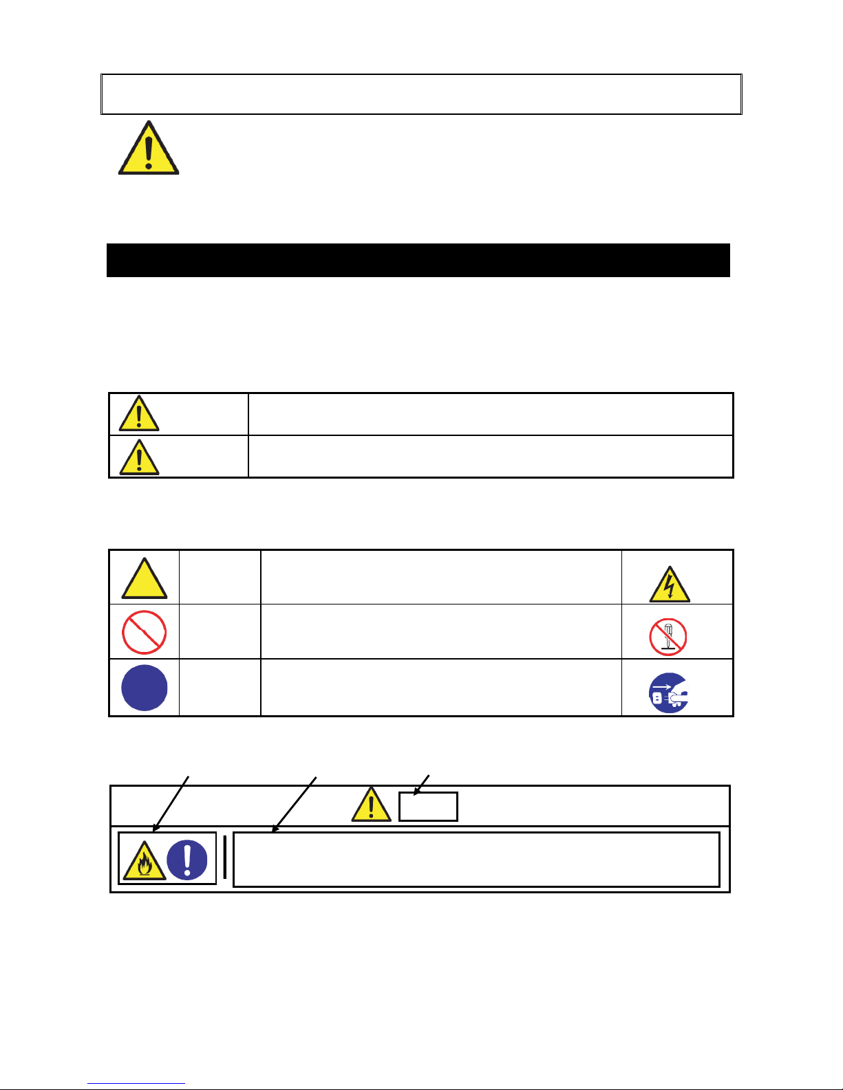
本製品を安全にお使いいただくために、このユーザーズガイドの指示に従って操作してください。
このユーザーズガイドには装置の何処が危険か、どうすれば危険を避けられるかなどについて説明さ
れています。ユーザーズガイドでは、危険の程度を表す言葉として、[警告]と[注意]という用語を使
用しています。それぞれの用語は次のような意味を持つものとして定義されています。
警告
人が死亡する、または重傷を負う恐れがあることを示します。
注意
火傷や怪我などを負う恐れや物的損害を負う恐れがあることを示します。
危険に対する注意・表示は
次の 3 種類の記号を使って表しています。それぞれの記号は次の意味を持つ
ものとして定義されています。
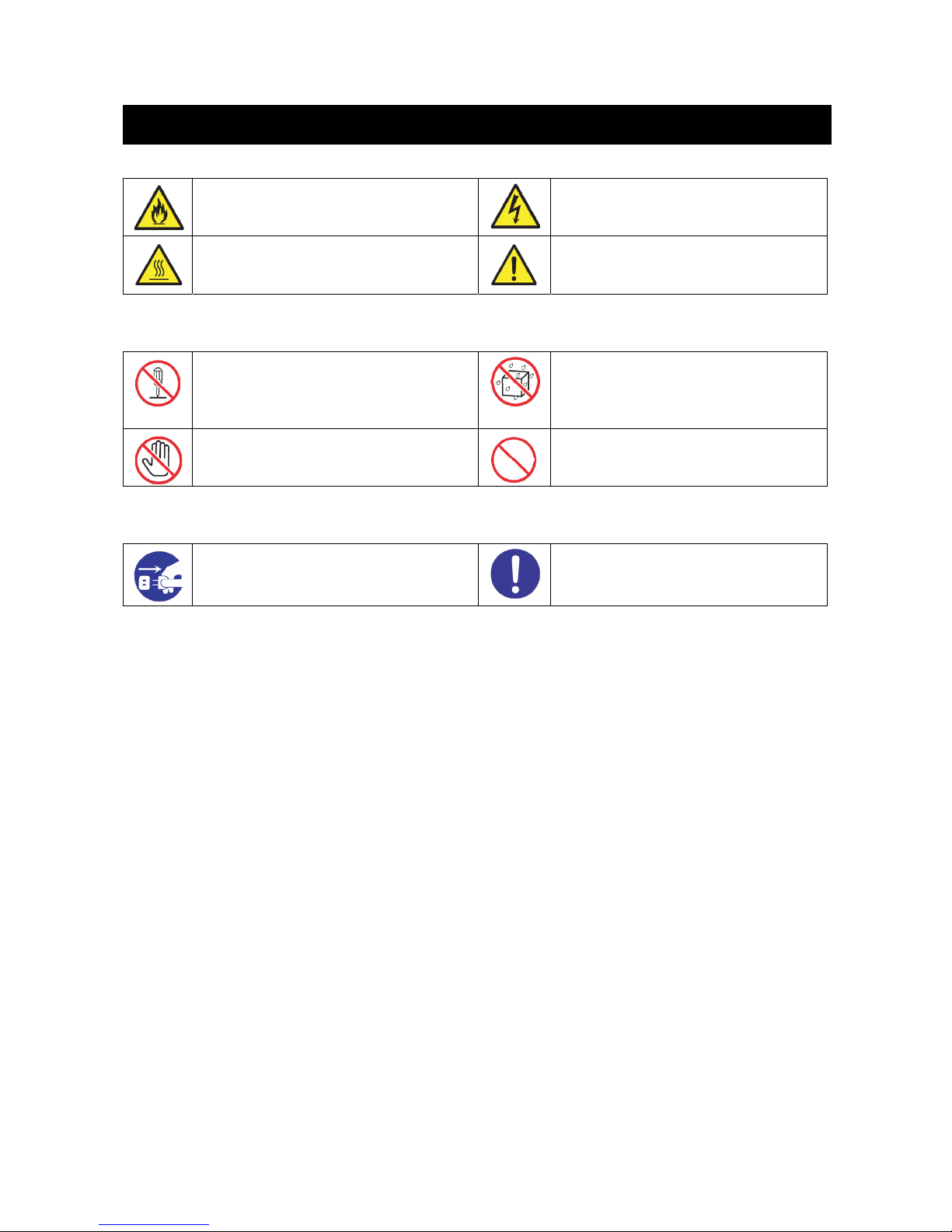
注意の喚起
この記号は危険が発生する恐れがあることを表します。記
号の中の絵表示は危険の内容を図案化したものです。
行為の禁止
この記号は行為の禁止を表します。記号の中や近くの絵表
示は、してはならない行為の内容を図案化したものです。
行為の強制
この記号は行為の強制を表します。記号の中の絵表示は、
しなければならない行為の内容を図案化したものです。危
険を避けるためにはこの行為が必要です。
(ユーザーズガイドでの表示例)
注意を促す記号 危険に対する注意の内容 危険の程度を表す用語
警告
安全に関わる表示について
例:分解禁止
例:感電注意
例:プラグを抜け
ビデオケーブル、変換コネクタ等を接続したら、ねじ止め等のロックを確実に
行ってください。接触不良を起こし、発煙や発火の原因となる恐れがあります。
インターフェースケーブルや本製品の電源ケーブルは確実に固定する
Page 3
2
ああ
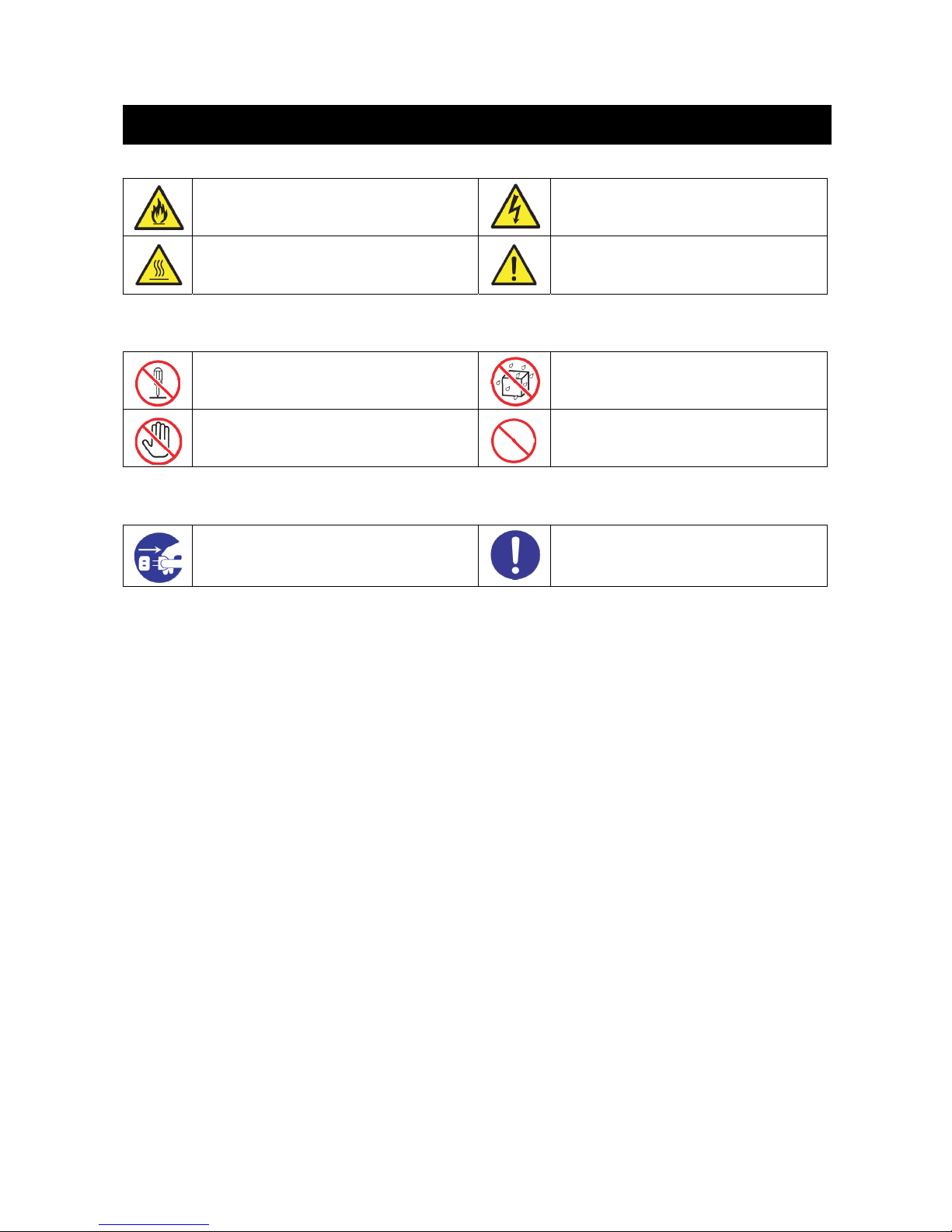
注意の喚起
発煙又は発火のおそれがあることを示し
ます。
感電のおそれのあることを示します。
高温による障害を負うおそれがあること
を示します
特定しない一般的な注意・警告を示しま
す。
行為の禁止
本製品を分解・修理・改造しないでくださ
い。感電や火災のおそれがあります。
水や液体がかかる場所で使用しないで
ください。水にぬらすと感電や発火のお
それがあります。
指定された場所には触らないでください。
感電や火傷などの障害のおそれがありま
す。
特定しない一般的な禁止を示します。
行為の強制
本体装置の電源プラグをコンセントから
抜いてください。火災や感電のおそれがあ
ります。
特定しない一般的な使用者の行為を指
示します。説明に従って操作をしてくだ
さい。
本書およびラベルで使用する記号とその内容
Page 4
3
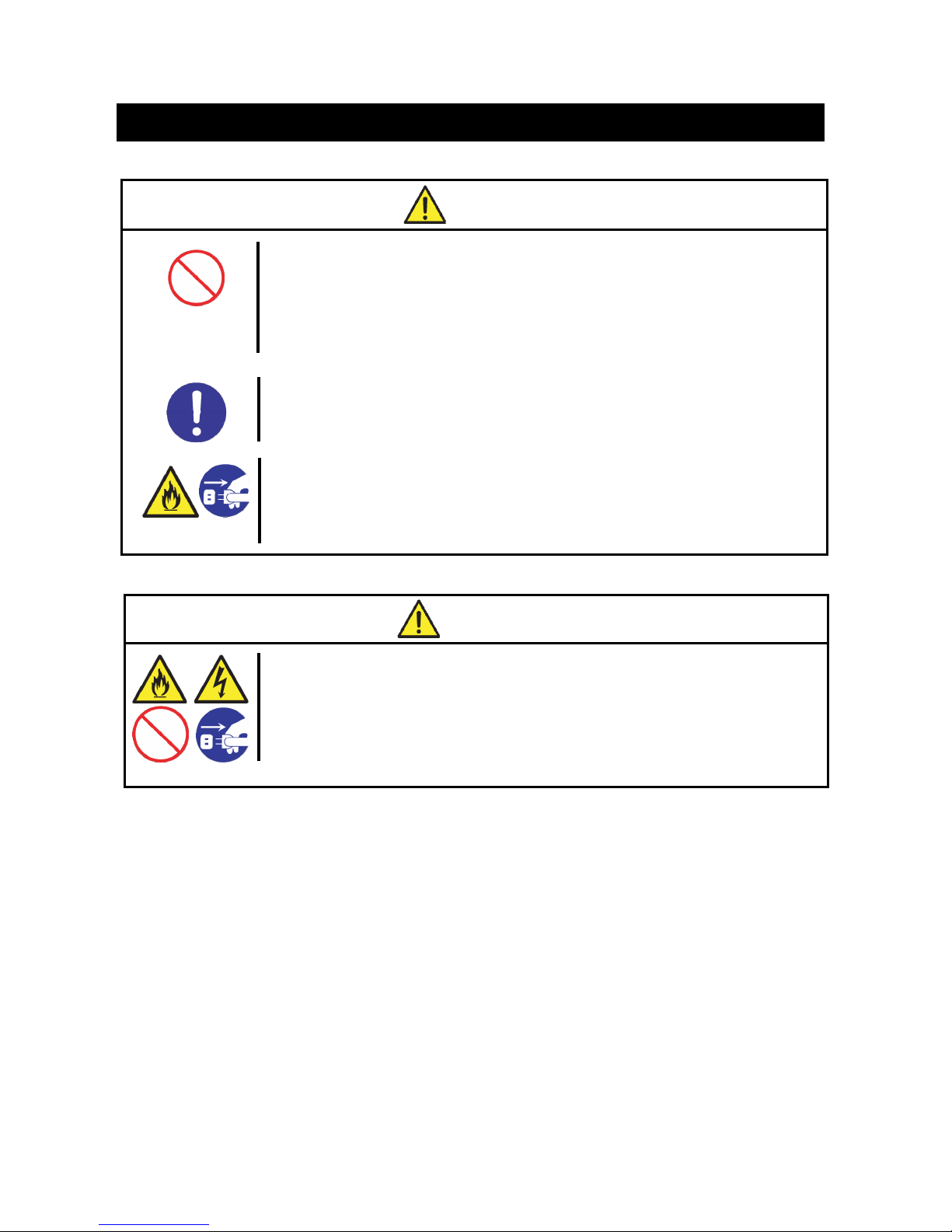
全般的な注意事項
注意
装置内に水や異物を入れない
本製品や本体装置内に水などの液体、ピンやクリップなどの異物を入れないで
ください。
火災や感電、故障の原因となります。もし入ってしまったときは、ただちに本体
装置の電源を OFF にして、本体装置の電源プラグをコンセントから抜いてくださ
い。分解しないで販売店または保守サービス会社にご連絡ください。
安全上のご注意 ~ 必ずお読みください ~
警告
人命に関わる業務や高度な信頼性を必要とする業務には使用しない
本製品は、医療機器・原子力設備や機器、航空宇宙機器・輸送設備や機器など、
人命に関わる設備や機器および高度な信頼性を必要とする設備や機器などへの
組み込みやこれらの機器の制御などを目的とした使用は意図されていません。
これらの設備や機器、制御システムなどに本装置を使用した結果、人身事故、財
産損害などが生じても当社はいかなる責任も負いかねます。
本体装置の警告、注意事項に従う
本製品を使用する際は、必ず本体装置の警告、注意事項に従ってください。
煙や異臭、異音がしたまま使用しない
万一、煙や異臭、異音などが生じた場合は、ただちに本体装置の電源を OFF にし
て、本体装置の電源プラグをコンセントから抜いてください。その後、お買い求
めの販売店または保守サービス会社にご連絡ください。そのまま使用すると火災
の原因となります。
Page 5
4
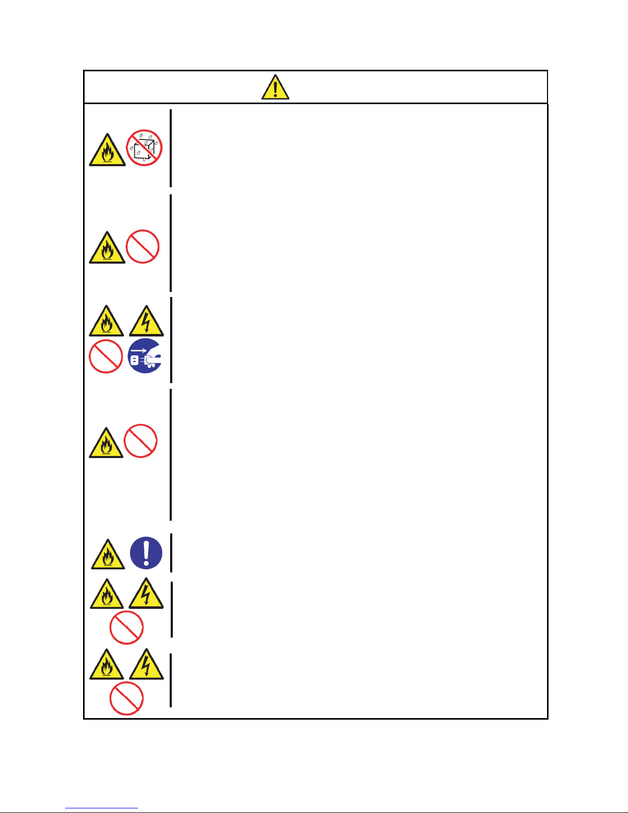
設置・保管・接続に関する注意事項
注意
指定以外の場所に設置・保管しない
本製品を次に示す場所や、本体装置で指定している場所以外に置かないでくださ
い。火災の原因となるおそれがあります。
・ほこりの多い場所。
・給湯器のそばなど湿気の多い場所。
・直射日光のあたる場所。
・不安定な場所
腐食性ガスの存在する環境で使用または保管しない
腐食性ガス(二酸化硫黄、硫化水素、二酸化窒素、塩素、アンモニア、オゾンな
ど)の発生する場所に設置し、使用しないで下さい。またほこり中に腐食を促進
する成分(塩化ナトリウムや硫黄など)や導電性の金属などが含まれている環境
へも設置しないで下さい。装置内部のプリント版が腐食・ショートし、火災の原
因となる恐れがあります。
もしご使用の環境で上記の疑いがある場合は、販売店または保守サービス会社に
ご相談ください。
本体装置の電源プラグを差し込んだまま本製品や本製品の電源ケーブル、インター
フェースケーブルの取り付けや取り外しをしない
本製品や本製品の電源ケーブル、インターフェースケーブルの取り付け/取り外
しは、本体装置の電源を OFF にして、本体装置の電源プラグをコンセントから抜
いて行ってください。たとえ本体装置の電源を OFF にしても本体装置の電源プラ
グを接続したままケーブルやコネクタに触ると感電したり、ショートによる火災
を起こしたりすることがあります。
指定以外のインターフェースケーブルや電源ケーブルを使用しない
インターフェースケーブルや電源ケーブルは、弊社が指定するものを使用し、接
続するモニタやコネクタを確認した上で接続してください。指定以外のものを使
用したり接続先を誤ったりすると、ショートにより火災をおこすことがありま
す。また、インターフェースケーブルや電源ケーブルの取り扱いや接続について
次の注意をお守りください。
・破損したケーブルコネクタを使用しない。
・ケーブルを踏まない。
・ケーブルの上に物を載せない。
・ケーブルの接続がゆるんだまま使用しない。
・破損したケーブルを使用しない。
インターフェースケーブルや本製品の電源ケーブルは確実に固定する
ビデオケーブル、変換コネクタ等を接続したら、ねじ止め等のロックを確実に行
ってください。接触不良を起こし、発煙や発火の原因となる恐れがあります。
インターフェースケーブルや本製品の電源ケーブルを持って引き抜かない
ケーブルを抜くときはねじ止め等のロックを外し、コネクタ部分を持ってまっす
ぐに引き抜いてください。ケーブル部分を持って引っ張ったりコネクタ部分に無
理な力を加えたりするとケーブル部分が破損し、火災や感電の原因となります。
本製品の電源ケーブルを他の製品や用途に使用しない
本製品の電源ケーブルは本製品に接続し、使用することを目的として設計され、
その安全性が確認されているものです。決して他の製品や用途に使用しないでく
ださい。火災や感電の原因となるおそれがあります。
Page 6
5
取り扱い・お手入れに関する注意事項
運用中の注意事項
注意
雷がなったら触らない
雷が鳴りだしたら、ケーブル類も含めて本体装置には触れないでください。ま
た、機器の接続や取り外しも行わないでください。落雷による感電のおそれが
あります。
警告
自分で分解・修理・改造はしない
本書に記載されている場合を除き、絶対に分解したり、修理・改造を行ったり
しないでください。本製品が正常に動作しなくなるばかりでなく、感電や火災
の危険があります。
注意
高温注意
本体装置の電源を OFF にした直後は、本製品を含め、装置内の部品が高温にな
っています。十分に冷えたことを確認してから取り付け/取り外しを行なって
ください。
Page 7

6
危険性がある部品やその周辺には警告ラベルがあります。これは本製品を取り扱うとき、考えられる
危険性を常にお客様に意識していただくためのものです(ラベルをはがしたり、塗りつぶしたり、汚
したりしないでください)。もし、このラベルが汚れている、印刷されていないなどのときは、販売
店にご連絡ください。
●警告ラベルの貼りつけについて
高温ラベルが添付されている場合は、本体背面に高温注意ラベルを貼り付けてください。
53Xi
55Xa 56Xg/56Xg-E
警告ラベル
高温注意ラベル貼付位置
高温注意ラベル貼付位置
Page 8
7
このたびは、グラフィックスアクセラレータ Quadro K5200 をご購入いただきありがとうございま
す。
本製品は当社のワークステーション Express5800 シリーズ上で動作する CAD や映像関連の OpenGL
アプリケーション専用に設計され、 Microsoft Windows 7、Microsoft Windows 8、
Microsoft Windows 8.1 に対応し、搭載されたグラフィックスアクセラレータ・チップ Quadro K5200
によって高速なグラフィックス描画が可能となるグラフィックスアクセラレータ・カードです。
本製品の持つ機能を最大限に引き出すためにも、ご使用になる前に本書をよくお読みになり、装置
の取り扱いを十分にご理解ください。
(1) 本書はグラフィックスアクセラレータ Quadro K5200 の取り扱い方法を説明しています。
本製品以外の機器については、それぞれの製品の説明書をご参照ください。
(2) 本書の内容の一部または全部を無断転載することは禁止されています。
(3) 本書の内容に関しては将来予告なしに変更することがあります。
(4) NEC の許可なく複製・改変などを行うことはできません。
(5) 本書は必要な時にすぐ参照できるよう大切に保管してください。
(6) 本書は内容について万全を期して作成いたしましたが、万一ご不審な点や誤り、記載もれなど
お気づきのことがありましたら、お買い求めの販売店にご連絡ください。
(7) 運用した結果の影響については(6)項にかかわらず責任を負いかねますのでご了承ください。
Microsoft, Windows, Windows 7, Windows 8, Windows 8.1, MS-DOS は米国 Microsoft Corporation
の米国およびその他の国における登録商標または商標です。
NVIDIA,Quadro は米国およびその他の国における NVIDIA Corporation の商標または登録商標です。
OpenGL は、Silicon Graphics, Inc.の登録商標です。
その他、記載の会社名および商品名は各社の商標または登録商標です。
本書では、Windows オペレーティングシステムを次のように表記します。
本書の表記 Windows OS の名称
Windows 7
Windows 7 Professional(32-bit)
Windows 7 Professional(64-bit)
Windows 8
Windows 8 Pro(32-bit)
Windows 8 Pro(64-bit)
Windows 8.1 Windows 8.1 Pro(64-bit)
はじめに
ご注意
商標について
オペレーティングシステムの表記
電波障害自主規制について
この装置は、クラスB情報技術装置です。この装置は、家庭環境で使用することを
目的としていますが、この装置がラジオやテレビジョン受信機に近接して使用される
と、受信障害を引き起こすことがあります。
取扱説明書に従って正しい取り扱いをして下さい。
VCCI-B
Page 9

8
単品で出荷時の場合、本製品には保証書がついています。内容をお確かめの上、大切に保管してく
ださい。本体装置組込み出荷時の場合は、本体装置の保証書及び本体装置のユーザーズガイドをご
覧ください。
保障期間後の修理についてはお買い求めの販売店、最寄の NEC または保守サービス会社に連絡して
ください。
・NEC 製以外(サードパーティ)の本体装置、NEC が認定していない装置やインターフェースケー
ブルを使用したために起きた故障については、その責任を負いかねますのでご了承ください。
Express5800 シリーズに関するご質問・ご相談は「ファーストコンタクトセンター」でお受けし
ています。
ファーストコンタクトセンター
TEL.03-3455-5800 (代表)
受付時間/9:00 ~12:00 、13:00 ~17:00 月曜日~金曜日(祝祭日、弊社休日を除く)
またインターネットでも情報を提供しています。
http://www.nec.co.jp/
NEC 製品に関するさまざまな情報が盛りだくさんのホームページです。
本ホームページに製品添付 DVD-ROM のディスプレイドライバのバージョンよりも新しいバ
ージョンが登録されていることがありますので、必要に応じてご確認ください。
http://club.express.nec.co.jp
Express5800 シリーズをご利用のお客様を対象にさまざまな特典やサービスを提供する
ClubExpress のホームページです。お客様登録や、登録の変更も出来ます。
本製品を第三者に譲渡(または売却)するときは、次の注意を守ってください。
・グラフィックスアクセラレータ本体について
本製品を第三者へ譲渡(または売却)する場合には、本書を含めすべての添付品を一緒にお渡し
ください。
・添付のソフトウェアについて
- 本製品に添付のソフトウェアを第三者へ譲渡(または売却)する場合には、全てを譲渡し、
譲渡した側は一切の複製物を保持しないこと
- ソフトウェアに添付されているソフトウェアのご使用条件の譲渡、移転に関する条件を満
たすこと
本製品の廃棄については、各自治体の廃棄ルールに従ってください。詳しくは、各自治体へお問い
合わせください。
保証について
情報サービスについて
第三者への譲渡について
製品の廃棄について
Page 10

9
目次
安全に関わる表示について .................................................................................................................................. 1
本書およびラベルで使用する記号とその内容 ................................................................................................. 2
安全上のご注意 ~ 必ずお読みください ~ ........................................................................................... 3
警告ラベル .................................................................................................................................................................... 6
はじめに ........................................................................................................................................................................ 7
ご注意 ............................................................................................................................................................................. 7
商標について .............................................................................................................................................................. 7
オペレーティングシステムの表記.................................................................................................................... 7
保証について .............................................................................................................................................................. 8
情報サービスについて ........................................................................................................................................... 8
第三者への譲渡について ....................................................................................................................................... 8
製品の廃棄について ................................................................................................................................................ 8
インストールの前に ............................................................................................................................................. 10
付属品の確認 ............................................................................ 10
動作環境の確認 .......................................................................... 10
1. インストレーション ...................................................................................................................................... 11
2. ハードウェアのインストール ................................................................................................................... 12
2.1 カードの取り扱いに関する注意事項 .................................................... 12
2.2 カードの実装 ........................................................................ 13
2.3 カードの取り外し .................................................................... 18
3. ソフトウェアのインストール/アンインストール .......................................................................... 19
3.1 ディスプレイドライバのインストール .................................................. 19
3.2 サウンドの出力先の変更方法 .......................................................... 21
3.3 ディスプレイドライバのアンインストール............................................... 23
4 コンフィグレーション .................................................................................................................................... 25
4.1 [Windows 7/ Windows 8/ Windows 8.1]でのコンフィグレーション .......................... 25
5.トラブルシューティング ............................................................................................................................ 37
5.1 画面が真っ暗で表示されない .......................................................... 37
5.2 起動時にブルーバック画面で止まってしまう ............................................. 37
5.3 ディスプレイドライバをインストールしても、VGAモードで起動してしまう .................. 37
5.4 音が鳴らない ........................................................................ 37
5.5 十分なパフォーマンスが得られない .................................................... 38
5.6 Windows 7/ Windows 8/ Windows 8.1で3Dグラフィックスアプリケーションが正しく動作しない 38
5.7 スタンバイから通常の表示状態に戻らない............................................... 38
5.8 機能制限について .................................................................... 38
6.各部の名称と機能 ........................................................................................................................................... 39
6.1 外観 ................................................................................ 39
6.2 製品仕様 ............................................................................ 40
6.3 画面モード一覧 ...................................................................... 40
6.4 モニタインターフェース・コネクタ仕様 ................................................ 42
Page 11

10
付属品の確認
本製品に添付されている「スタートアップガイド」を参照して、すべてがそろっているか確認しそれぞ
れ点検してください。万一足りないものや損傷しているものがある場合は、販売店に連絡してください。
動作環境の確認
本体装置
本製品は PCI-Express スロット搭載の当社のワークステーション Express5800 シリーズ上で動作しま
す。
本製品の対応機種、ご利用いただく時の制限事項などにつきましては販売店に確認してください。
また、当社が動作保証していない拡張ボードと本装置を組み合わせた場合には、本製品の動作保証を
致しかねますのでご了承ください。
オペーレーティングシステム
本製品は Windows 7、Windows 8、Windows 8.1 が正常に動作する環境でお使いいただけます。
モニタ
本製品の解像度、リフレッシュレートに適合したモニタをご使用ください。モニタによってはサポー
トする解像度やリフレッシュレートが異なりますのでご注意ください。
インストールの前に
Page 12

11
本章ではハードウェア/ソフトウェアのインストールについて説明します。インストールを行うシステムに
実装されているグラフィックスアクセラレータの有無によってインストレーションの手順が変わってきます
ので、下記の手順にしたがってインストールを実施してください。
またフリーセレクションでQuadro K5200を実装済みのシステムについても、ディスプレイドライバのインス
トール作業が必要になりますのでご注意ください。
(1)Quadro K5200以外のグラフィックスアクセラレータからQuadro K5200に変更する場合には、インスト
ールを行う前に他のディスプレイドライバをアンインストールしてください。
またディスプレイドライバのアンインストール後には再起動を行い、正常に起動できることを確認し
てください。
※ディスプレイドライバのアンインストール方法がわからない場合には、以下の手順を実施してください。
[Windows 7の場合]
①
[コントロールパネル]の[プログラム]配下にある[プログラムのアンインストール]をクリックする。
(クラシック表示の場合は[コントロールパネル]の[プログラムの機能]をクリックする。)
②
インストールされているプログラムリストから該当するドライバをダブルクリックしてアンインスト
ールする。
③
Windowsの再起動を行う。
※
再起動後にWindowsのINBOXディスプレイドライバがインストールされる場合があります。再起動を要求
された場合は、指示に従いもう一度再起動を行ってください。
[Windows 8の場合]
①
[コントロールパネル]の [プログラムのアンインストール]をクリックする。
(表示方法が「大きいアイコン」または「小さいアイコン」表示の場合は、[プログラムと機能]をクリ
ックする。)
②
インストールされているプログラムリストから該当するドライバをダブルクリックしてアンインスト
ールする。
③
Windowsの再起動を行う。
※ 再起動後にWindowsのINBOXディスプレイドライバがインストールされる場合があります。再起動を要求
された場合は、指示に従いもう一度再起動を行ってください。
[Windows 8.1の場合]
①
[コントロールパネル]の [プログラムのアンインストール]をクリックする。
(表示方法が「大きいアイコン」または「小さいアイコン」表示の場合は、[プログラムと機能]をクリ
ックする。)
②
インストールされているプログラムリストから該当するドライバをダブルクリックしてアンインスト
ールする。
③
Windowsの再起動を行う。
※ 再起動後にWindowsのINBOXディスプレイドライバがインストールされる場合があります。再起動を要求
された場合は、指示に従いもう一度再起動を行ってください。
(2)基本装置の電源がOFFになっている事を確認して、電源プラグを抜き、 「2. ハードウェアのインス
トール」を参照してQuadro K5200カードを基本装置に取り付けてください。
(3)Windowsのインストール (インストール済みの場合は読み飛ばしてください)
(4)「3.1 ディスプレイドライバのインストール」を参照してディスプレイドライバをインストールして
ください。
以上の手順でインストールを行ってください。
1. インストレーション
Page 13
12
2.1 カードの取り扱いに関する注意事項
・
本製品の本体装置への取り付けは、お買い求めの販売店または保守サービス会社に依頼することをお
勧めします。また取り付けの際は本体装置に添付されているユーザーズガイドもあわせてご参照くだ
さい。
・ 本製品に使用されている電子部品は静電気によって破壊される可能性があります。本製品を取り扱う
際には身体の一部をアースする等の静電気対策を行ってください。また部品面やコネクタ類には直接
手を触れないで、リアパネルや基盤の端を保持するようにしてください。
怪我防止のためにも、本製品を取り扱う際には静電気防止手袋を着用して作業してください。
・ 本製品を本体装置に取り付けや取り外しを行う場合、および本製品に接続するケーブル類を取り付け
や取り外しを行う場合は、必ず本体装置及び周辺装置の電源を切り、電源ケーブルをコンセントから
抜いた状態で行ってください。
・ お客さまが本製品の取り付け、取り外しの作業中、万一ネジやクリップなどの導電物質を本体装置内
に落下させ取り出すことが困難な場合は、お買い求めになった販売店または保守サービス会社にご相
談ください。
・ 本製品のそばでは携帯電話や PHS、ポケットベルの電源を OFF にしておいて下さい。電波による誤動
作の原因となります。
注意
電源コードを抜く
本体装置が稼動している場合、本体装置上で動いているアプリケーションをすべて終了さ
せ、本体装置及び周辺装置の電源を切って、電源プラグをコンセントから抜いてください。
高温注意
本体装置の電源を切った直後は、装置内部が高温になっています。充分に冷えたことを確認
してからボードの取り付けを行ってください。
2. ハードウェアのインストール
Page 14
13
2.2 カードの実装
(1) 本体装置と周辺装置の電源が切れている事を確認して、本体装置の電源プラグを抜く。
(2) 本体装置に添付されているユーザーズガイドにしたがって本体装置のカバーを取り外す。
(3) 本体装置に添付のユーザーズガイドにしたがって、PCI-Express(x16)スロットのスロットカバー、
もしくは実装されている PCI-Express カードを固定しているねじもしくは固定治具を外しスロット
カバーまたは PCI-Express カードを取り外す。
※本体装置によってはカード固定ねじ/固定治具のほかに PCI-Express スロットにカード固定
機構が用意されていますのでご注意ください。
※特に 2 枚幅のカードは、固定機構が直接見えないため、慎重に操作してください。力を加えす
ぎるとロックレバーを破損する恐れがあります。
(4) Quadro K5200 の PCI-Express カードエッジコネクタを本体装置の PCI-Express x16 スロットに奥
まで確実にセットされるように、しっかりと挿し込んでください。
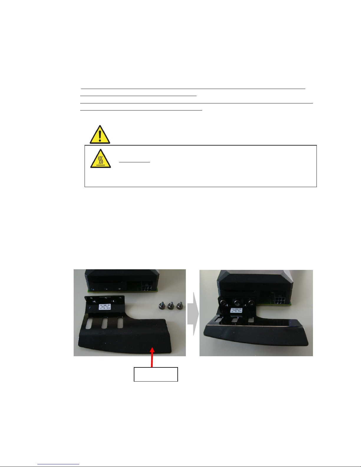
リテーナについて
55Xa へ Quadro K5200 を接続する場合には、下図 1~3 を参考に添付のリテーナを取り付けてから
本体装置へ接続を行ってください。
56Xg/56Xg-E、53Xi へ Quadro K5200 を接続する場合は、本体装置に固定レール(図 2)がないため、
リテーナの取り付け(図 1)は不要です。
図1
注意
高温注意
本体装置の電源を切った直後は、装置内部、PCI-EXPRESS カードが高温になっています。
充分に冷えたことを確認してから PCI-Express カードの取り外してください。
リテーナ
Page 15
14
図2
図3
※PCI-Express x16 スロットの近くにメモリスロットがある場合は、メモリロックレバーがきちんと
起きていることを確認して接続してください。
※PCI-Express x16 スロットにロックレバーがある場合、接続時にロックレバーが破損する恐れがあ
りますので、ロック部分に十分注意しながら接続してください。
注意
無理な力を加えない
うまくカードが取り付けられない時は、カードを一度取り外してから再度取り付け直してく
ださい。カードに過度の力を加えると破損するおそれがあります。
また実装時にカード上の部品(ヒートシンクやコンデンサ等)に力が加わらないようにして
ください。
メモリロックレバー
PCI-Express x16 スロットロックレバー
[55Xa の場合]
リテーナを本体装置の固定レールに合わ
せながら接続を行う。
PCI-Express カードエッジコネクタを本体
装置の PCI-Express x16 スロットにカード
が奥まで確実にセットされるように、しっ
かりと挿し込む。
Page 16

15
(5) カードの接続が終わりましたら、ボードがしっかりささっていることを確認してから、取り外し
たねじもしくは固定治具で Quadro K5200 を固定して下さい。
このとき、背面から見て Display-Port コネクタと DVI-I コネクタが本体装置のスロットと平行に
なっていることを確認してください。
※高温注意ラベルが添付されている場合は、本体装置背面に高温注意ラベルを貼り付けて下さい。
本体装置ごとの高温注意ラベルの貼付位置は、警告ラベルの章を参照してください。
(6) Quadro K5200 カード上の PCI-Express 外部電源コネクタ(6ピン)に、電源ユニットから対応コネ
クタを接続してください。なお本体装置の電源ユニットに対応コネクタが用意されていない場合
には、添付の PCI-Express 外部電源ケーブルの6ピン側を Quadr K5200 に接続して、4ピンの電
源コネクタには、対応する本体装置の電源ケーブルを接続してください。
高温注意ラベル
貼付位置
Display-Port コネクタ
DVI-I コネクタ
DVI-D コネクタ
コネクタとスロットが
平行になっていること
PCI-Express 外部電源ケーブル
Quado K5200 の PCI-Express 外部
電源コネクタに接続
本体装置の電源ケーブルに接続
Page 17
16
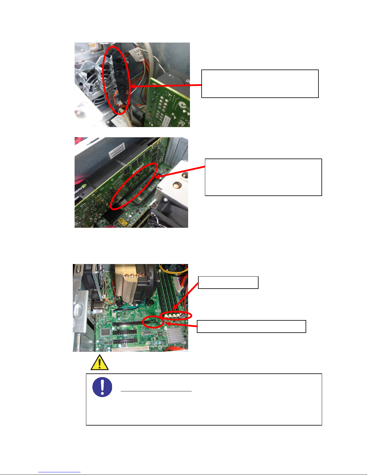
また、本体装置の電源ケーブルが不足する場合には別途添付してあります電源分岐ケーブルを使用
して電源コネクタの口を増設してご使用してください。
※ケーブルの長さが余る場合には、コネクタが金属部に接触しないように、またファンや板金等に
噛みこまないようにまとめてください。
※PCI-Express 外部電源ケーブルまた HDD や ODD へ接続する SATA ケーブルのルーティングは下の図
のように行ってください。
本体装置により電源ケーブルの接続方法が異なります。本体装置のユーザーズガイドを参照して
ください。
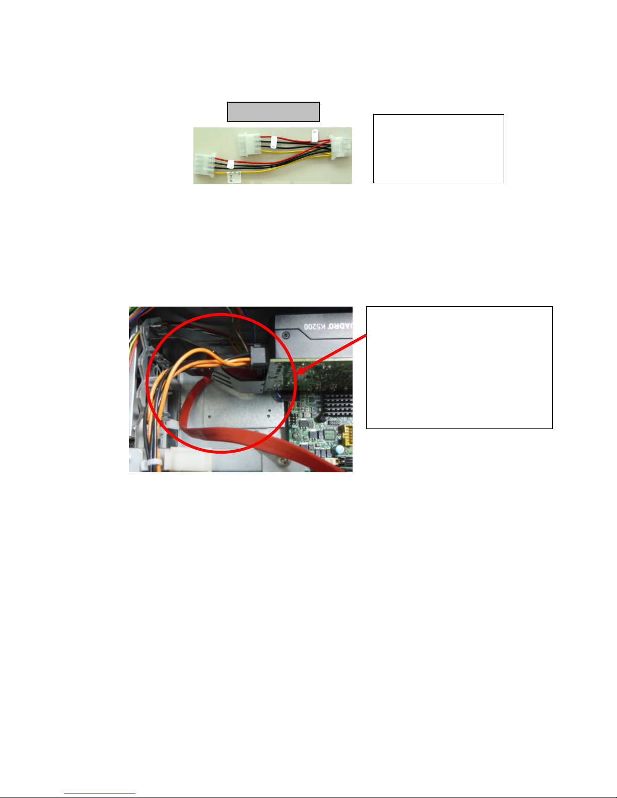
凸(オス)のコネクタを本体
装置の電源コネクタに
凹(メス)のコネクタは普通
の本体電源コネクタと同様
にご使用いただけます。
電源分岐ケーブル
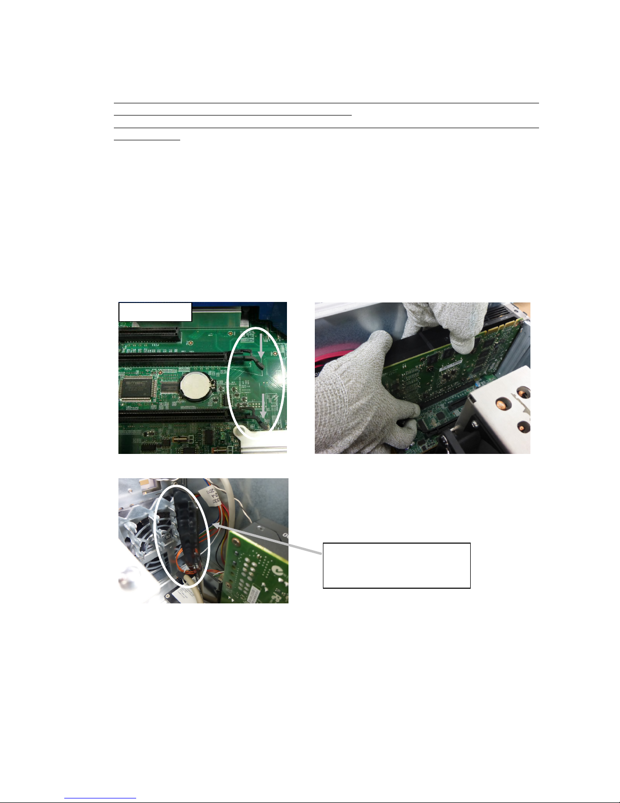
PCI-Express 外部電源ケーブルは、Quadro
K5200 の上を通してコネクタへ接続して
ください。
HDD や ODD に接続する SATA ケーブルは、
Quadro K5200 のリテーナ付近の下を通し
て各デバイスへ接続してください。
Page 18

17
(7) モニタケーブルの接続
Quadro K5200 は映像出力用に、DVI-I コネクタを 1 つ、DVI-D コネクタを 1 つ、Display-Port コ
ネクタを 2 つの計 4 つのコネクタを持っています。モニタへの接続方法は、次のように行ってく
ださい。
アナログモニタ(CRT モニタ、LCD モニタ)に接続される場合
アナログモニタの接続は、DVI-I コネクタにしか行えません。
Quadro K5200 カードの DVI-I コネクタに付属の DVI-VGA 変換コネクタを接続して固定用ネジで
本体装置に確実に固定してから、変換コネクタの VGA コネクタにビデオケーブルを接続してビデ
オケーブル固定用ネジで確実に固定してください。
デジタルモニタに接続される場合
① DVI 対応 LCD モニタ
Quadro K5200 カードの DVI-I コネクタ又は DVI-D コネクタに、モニタのビデオケーブルを接
続して固定用ねじで確実に固定してください。
もしくは、Quadro K5200 の Display-Port コネクタに別売りの DP-DVI 変換コネクタを接続し
てロック機構で確実に固定した後、DP-DVI 変換コネクタの DVI-D コネクタにモニタのビデオ
ケーブルを接続して固定用ねじで確実に固定してください。
② Display-Port 対応 LCD モニタ
Quadro K5200 カードの Display-Port コネクタに、モニタからのビデオケーブルコネクタを
接続してください。
※複数画面で使用される場合は、プライマリモニタとセカンダリモニタを「6.4 モニタインターフェー
ス・コネクタ使用」を参考にして接続してください。
※4 つのコネクタすべてにモニタケーブルを接続して 4 画面出力が可能です。
(8) (2)で取り外した本体装置のカバーを元に戻して本体装置の電源ケーブルを接続する。
以上でハードウェアのインストールは完了です。
※電源投入時に「ピーピッピ」または「ピ、ピ、ピ、ピ、ピ」とブザー音がする場合には、Quadro K5200
が正しく認識されていません。その場合にはカードが PCI-EXPRESS スロットに確実に奥まで差し込
まれているか確認して、再度 PCI-EXPRESS スロットに接続しなおしてください。
※Quadro K5200 を 2 枚実装している場合や Tesla K20 と組み合わせて実装している場合には、次の手
順で正しく認識されていることを確認してください。正しく認識されていない場合には、カードが
PCI-EXPRESS スロットに確実に奥まで差し込まれているか確認して、再度 PCI-EXPRESS スロットに
接続しなおしてください。
[Windows 7の場合]
①
スタートボタンをクリックし、スタートメニューから[コンピュータ]を右クリックし、[管理]をクリッ
クします。
②
コンピュータの管理画面が表示されます。ウィンドウ左の一覧から[デバイスマネージャー]をクリック
します。
③
デバイスマネージャーの一覧から[ディスプレイアダプター]項目の左側にある[▷ ]をクリックして、デ
ィスプレイアダプターの一覧を表示します。
④
Quadro K5200が表示されているか、[?]や[!]が表示されていないか確認します。
[Windows 8/ Windows 8.1の場合]
①
スタート画面左下にマウスをあわせて右クリックし、[デバイスマネージャー]をクリックします。
②
デバイスマネージャーの画面が表示されます。一覧から[ディスプレイアダプター]項目の左側にある
[▷ ]をクリックします。
③
Quadro K5200が表示されているか、[?]や[!]が表示されていないか確認します。
Page 19
18
2.3 カードの取り外し
※カード取外しの際には、PCI-Express スロットにある固定機構(図1)の解除方法を確認し、正しく
解除した上でカードの取り外しを行う必要があります。
※固定機構が解除されないままカードの取り外しを行うと、固定機構が破損する恐れがありますのでご
注意ください。
(1) 本体装置と周辺装置の電源が切れている事を確認して、本体装置の電源プラグを抜く。
(2) 本体装置と接続しているモニターを外す。
(3) 本体装置に添付されているユーザーズガイドにしたがって本体装置のカバーを取り外す。
(4) Quadro K5200 の PCI-Express 外部電源コネクタに接続している、PCI-Express 外部電源ケーブルを
外す。
(5) Quadro K5200 を固定しているリアブラケットのねじ、もしくは固定治具を外す。
(6) PCI-Express スロットにあるカード固定用機構のロック部分(図 1)を指で矢印の方向に押しなが
ら Quadro K5200 を取り外す。
注意)55Xa は Quadro K5200 のリテーナと本体装置の固定レール(図 3)があるため、ロック部分(図
1)を指で押しながら、Quadro K5200 の平行を保ちながらまっすぐ上に引き抜いて(図 2)、
PCI-Express スロットから取り外す。
図1 図2
図3
(7) PCI-Express(x16)スロットのスロットカバーを付けて、ねじもしくは固定治具で固定する。
(8) 本体装置のカバーを元に戻す。
[55Xa の場合]
Quadro K5200 のリテーナと本体
装置の固定レール
ロック部分
Page 20

19
3.1 ディスプレイドライバのインストール
(1) 添付の「3D Graphics Accelerator nVIDIA Display Driver」DVD-ROM ディスクを用意する。
(2) OS を起動後 Administrator 権限のあるアカウントでログインする。
※OS の PnP 機能により本製品が検出され、[新しいハードウェアの検出ウィザード]が起動すること
があります。この場合には[キャンセル]ボタンをクリックしてウィザードを終了してください。
(3) 用意した DVD-ROM を DVD-ROM ドライブにセットする。
(4) スタートメニューから [すべてのプログラム]→[アクセサリ]→[エクスプローラ]をクリックする。
(5) Windows 7 32-bit の場合は[Win7]フォルダにある[Setup.exe]を
Windows 7 64-bit の場合は[Win7_64]フォルダにある[Setup.exe]を
Windows 8 32-bit の場合は[Win8]フォルダにある[Setup.exe]を
Windows 8 64-bit の場合は[Win8_64]フォルダにある[Setup.exe]を
Windows 8.1 64-bit の場合は[Win81_64]フォルダにある[Setup.exe]を
ダブルクリックしてディスプレイドライバのインストーラを起動する。
※ご使用の OS に合うファイルを正しく選択してください。異なる OS のドライバをインストールす
ると正常に動作しませんのでご注意ください。
3. ソフトウェアのインストール/アンインストール
Page 21

20
(6) Windows 7/Windows 8/ Windows 8.1 のインストール
※Windows 7/Windows 8/ Windows 8.1 の場合、[Setup.exe]をクリックするとユーザーアカウント
制御に関する許可を求められますが、[続行]または[はい]をクリックしてインストールを続けて
ください。
(7) 以上でディスプレイドライバのインストールは完了です。
ディスプレイドライバのインストール後、「4 章 コンフィグレーション」を参考にして画面の解像度、
画面の色、リフレッシュレートなどの設定を行ってください。
正常に動作しない場合は、もう一度再起動を行ってください。
[同意して続行する(A)]ボタンをクリック
インストールする形式の選択を行います。
[高速(推奨)(E)]にチェックが入っていることを
確認して[次へ(N)]ボタンをクリック
[閉じる(C)]ボタンをクリック
再起動を促すメッセージが表示された場合は、再
起動してください。
Page 22
21
3.2 サウンドの出力先の変更方法
Quadro K5200とディスプレイをDisplayPortで直接接続すると、サウンドの出力先が接続先のディスプレイ
になる場合があります。このとき本体装置のスピーカーから音が鳴りませんので本体装置から出力したい
場合は、以下の手順で設定を変更してください。
ディスプレイから音を出力させたい場合はディスプレイを出力先としてください。
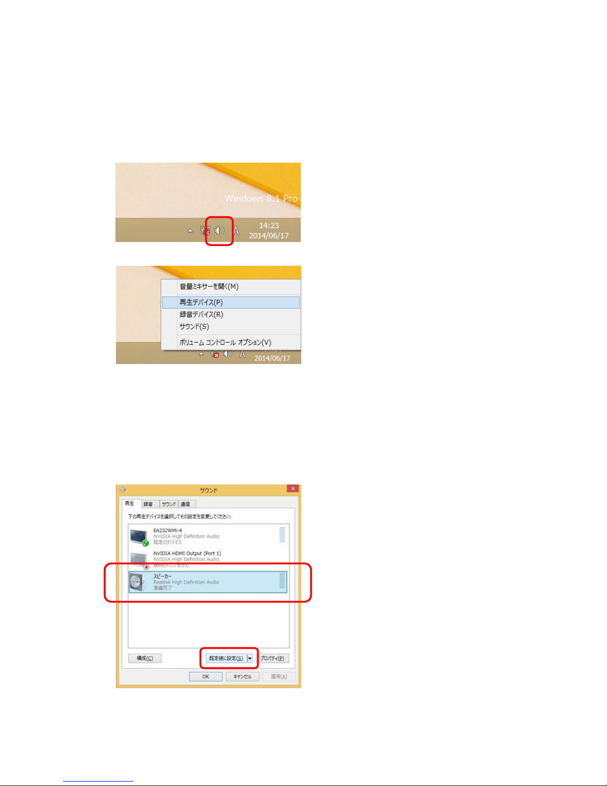
(1) 画面右下のサウンドのアイコンを右クリックします。
(2) [再生デバイス(P)]をクリックします。
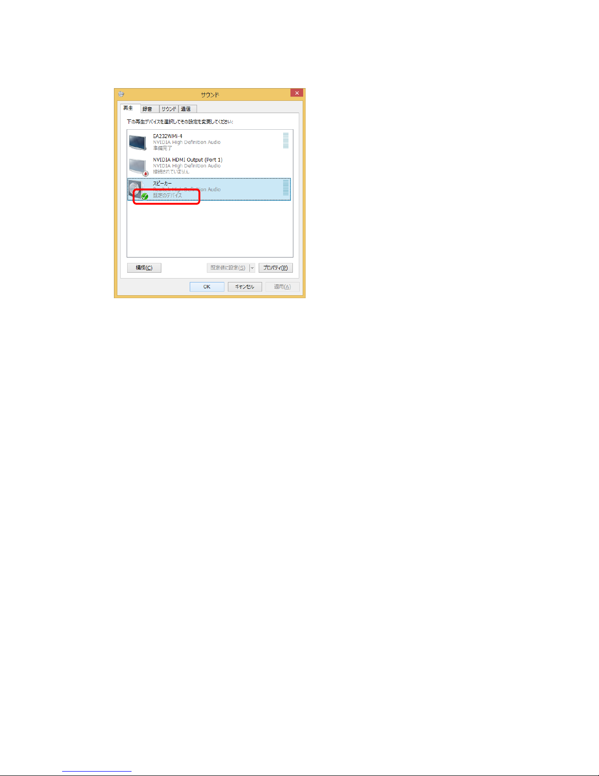
(3) 以下のような画面が開きます。
ここで現在の設定内容を確認し、出力したいデバイスを選択して出力先の変更をします。
例)
[NVIDIA High Definition Audio]が既定のデバイスとなっている場合、[Realtek High Definition
Audio]を選択し、[既定値に設定(S)]をクリックします。
・[NVIDIA High Definition Audio]が DisplayPort の接続先ディスプレイからの出力です。
・スピーカー(※)が本体装置からの出力です。
(※) [Realtek High Definition Audio]などは装置によって名称が異なる場合があります。
Page 23
22
(4) スピーカーが既定のデバイスとなっていることを確認し、[OK]をクリックします。
これで本体装置のスピーカーから音が鳴ります。
Page 24
23
3.3 ディスプレイドライバのアンインストール
以下の手順に従ってディスプレイドライバをアンインストールしてください。
(1) OS を起動後 Administrator 権限のあるアカウントでログインする。
(2) [Windows 7]の場合は、[スタートメニュー]⇒[コントロールパネル]⇒[プログラムのアンインスト
ール]の順にクリックする。
[Windows 8]の場合は、スタート画面で右クリックし、画面右下[すべてのアプリ]⇒[コントロール
パネル]⇒[プログラムのアンインストール]の順にクリックする。
[Windows 8.1]の場合は、スタート画面左下で右クリックし、[コントロールパネル] ⇒[プログラム
のアンインストール]の順にクリックする。
※HDAudio ドライバは別途個別にアンインストールする必要があります。
ドライバアンインストールと同様の手順でアンインストールを行ってください。
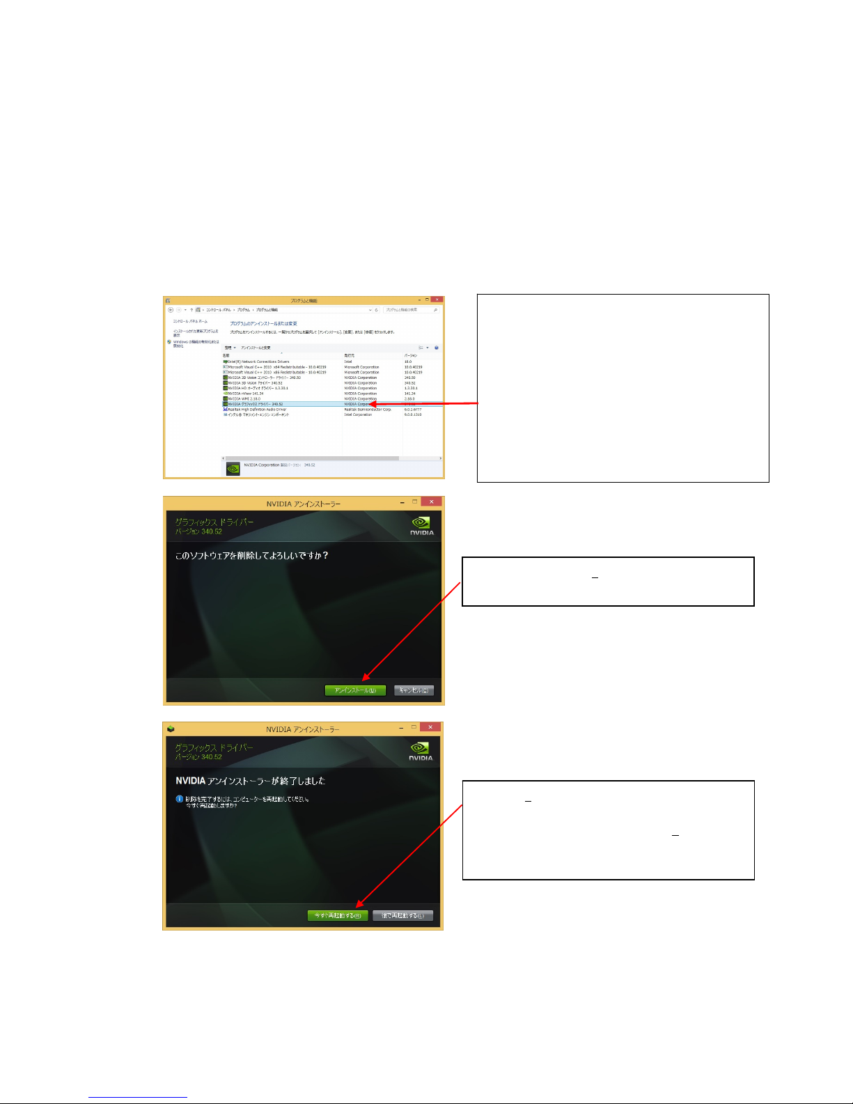
[アンインストール(U)]ボタンをクリックして
アンインストールを続行してください。
インストールされているプログラム一覧から
[NVIDIA グラフィックス ドライバー xxx.xx]
をダブルクリックしてアンインストールを開
始してください。
※ OS に対応したドライバーバージョンが表示
されます。
※ このとき、ユーザーアカウント制御に関す
る許可を求められた場合は[続行]または
[はい]をクリックしてアンインストールを
続けてください。
[閉じる(C)]ボタンをクリックしてください。
※ OS により[今すぐ再起動する(R)]ボタンが
ある場合は、クリックして再起動を行って
ください。
Page 25

24
(3) [閉じる(C)]をクリックしてアンインストーラーを終了させます。
OS によりアンインストールが終わると、再起動を要求される場合があります。その場合は、アンイ
ンストールを反映させるためにシステムの再起動が一度必要になりますので、再起動を行ってくだ
さい。
以上で、ディスプレイドライバのアンインストールは完了です。
Page 26
25
本章では、画面設定及び[NVIDIA コントロールパネル]でのコンフィグレーションについて説明します。
4.1 [Windows 7/ Windows 8/ Windows 8.1]でのコンフィグレーション
[画面の解像度]から行なうことのできる、Quadro K5200のコンフィグレーションについて説明
します。
※ Windows 7/ Windows 8/ Windows 8.1 上でコンフィグレーションを設定する場合には[管 理者
(Administrator)]としてログオンする必要があります。
※ [画面の解像度]のウィンドウは、次の方法で呼び出すことができます。
・[コントロールパネル]⇒[画面の解像度の調整]の順にクリックします。
・デスクトップ上で右クリックを行い表示されたメニューから[画面の解像度(C)]の順にクリック
します。
4.1.1 複数画面の設定
Quadro K5200 では、4 つのディスプレイをそれぞれ独立して使用することができます。
複数画面の設定は、以下のように行います。
ここでは、複数画面の設定や、画面の領域(解像度)の設定をすることができます。
さらに、[詳細設定]ボタンで[Quadro K5200]のプロパティを呼び出し、[モニタ]タブにて、リフ
レッシュレート、色数などの設定を行うことができます。
4 コンフィグレーション
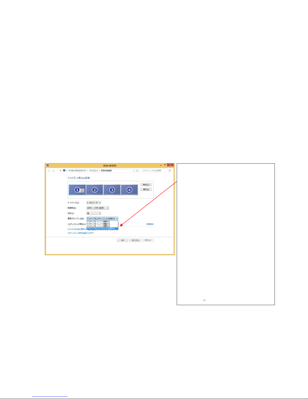
① 「複数のディスプレイ(M)」のプルダウ
ンメニューにて選択
・[デスクトップを 1 と 2 に複製する]
クローン表示します
・[デスクトップを 1 と 3 に複製する]
クローン表示します
・[デスクトップを 1 と 4 に複製する]
クローン表示します
・[デスクトップをこのディスプレイ
に拡張する]
現在選択中のディスプレイが未使
用の場合、使用可能にします。
画面を拡張する場合は拡張したいディス
プレイを選択し、「デスクトップをこのデ
ィスプレイに拡張する」を選択します。
② [適用(A)]をクリックする
Page 27
26
4.1.2 画面の解像度、表示色数、リフレッシュレートの設定
・画面の解像度
画面の解像度の変更は、[画面の解像度]で行うことができます。
・画面の解像度について
画面の解像度が大きいほど多くの情報を同時に表示することができますが、反対に画素(ピクセル)のサ
イズは小さくなり表示が見にくくなる場合があります。また表示できる最大の解像度は接続するモニタ
の性能にも左右されるのでモニタの取り扱い説明書を参照して設定を行ってください。
CRT モニタの場合: 以下の表を参考にモニタに合った解像度を選択してください。
モニタ種別 推奨解像度
15 インチ CRT 640x480 ~ 1024x768 ピクセル
17 インチ CRT 1024x768 ~ 1280x1024 ピクセル
22 インチ CRT 1280x1024 ~ 1600x1200 ピクセル
LCD モニタの場合: 推奨解像度が各モニタで決まっていますので、モニタの取り扱い説明
を参照して推奨の解像度に設定してください。
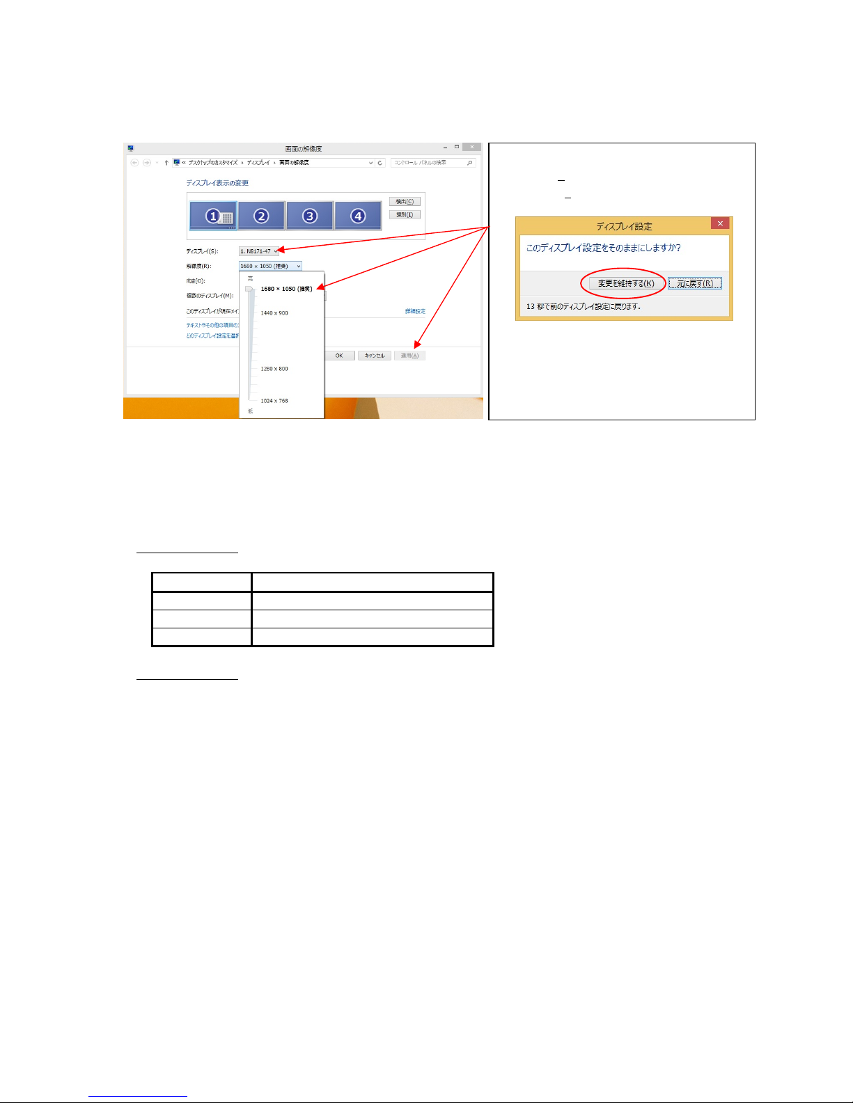
解像度を変更するディスプレイを選択し、
「解像度(R)」のスライダーで解像度を調整
して[適用(A)]をクリックしてください。
変更する解像度によっては上のようなポッ
プアップウィンドウが現れます。変更内容
が適切であることを確認して[変更を維持
する(K)]をクリックしてください。
Page 28
27
・表示色数の設定
画面の表示色数の変更は、[画面の解像度]にある[詳細設定(V)]をクリックして現れる[汎用 PnP と
NVIDIA Quadro K5200 のプロパティ]で行ないます。[モニタ]のタブをクリックし[色(C)]のプル
ダウンメニューから表示したい色数を選択して、[OK]をクリックしてください。
※8 ビット(256 色)を選択したい場合は、[アダプタ]タブの[モードの一覧]から行ってください。
・表示色数について
Quadro K5200 では、256 色、65536 色、TrueColor の表示色数をサポートしています。表示色数の違いは、
同時に表現できる色数の差になります。また表示色数によって消費するビデオメモリ量が変化するので、
下記の表を参考にカラーパレットを設定してください。
表示色数 BPP(Bit Per Pixel) 表示色数 主な用途
256 色 8 16,777,216 色のうち、256 色を表示可能 多色表示を必要としないビジネスアプリケー
ション等
65536 色 16 同時に 65,536 色表示可能
(緑:64 階調、赤・青:各 32 階調表示)
ゲームや、CAD/CG アプリケーション等で特に
高速性が必要な場合
TrueColor 32 同時に 16,777,216 色表示可能、
(32BPP の 32bit のうち色情報に 24bit
を使用、赤・緑・青で各 256 階調表示)
CAD/CG アプリケーション等
・リフレッシュレートの設定
リフレッシュレートの設定は、[画面の解像度]にある[詳細設定(V)]をクリックして現れる[汎用 PnP と
NVIDIA Quadro K5200 のプロパティ]で行います。[モニタ]のタブをクリックし[画面のリフレッシュレ
ート(S)]のプルダウンメニューから変更したいリフレッシュレートを選択して、[適用(A)]をクリックし
てください。
・リフレッシュレートについて
リフレッシュレートは 1 秒間に行う画面書き換え回数のことで、リフレッシュレートが高いほど画面の
ちらつきを抑えることができます。しかし、リフレッシュレートを上げるほどグラフィックスの描画性
能は下がりますので注意してください。
LCD モニタでは残像時間が長いことから CRT モニタに比べて高いリフレッシュレートを必要としません。
また、リフレッシュレートの上限は接続するモニタによって異なっています。
※複数画面の設定、画面の解像度、表示色数、リフレッシュレートの設定は、[NVIDIA コントロールパネ
ル]からも行うことができます。[NVIDIA コントロールパネル]での設定方法は、次項で説明します。
Page 29
28
4.1.3 NVIDIAコントロールパネル
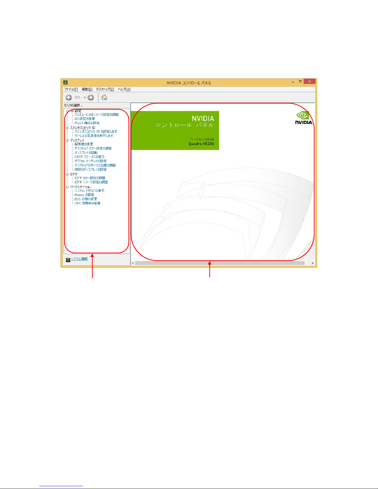
・[NVIDIA コンロトールパネル]の表示
[NVIDIA コントロールパネル]起動するには、デスクトップ上で右クリックをして現れるメニューから
[NVIDIA コントロールパネル]を選択してクリックします。
・[NVIDIA コントロールパネル]では、メインタスクペインとナビゲーションツリーペインを使いドライバ
ーの設定を行います。
・メインタスクペインは、グラフィックスドライバの設定を行う場所です。次回以降、コントロールパネ
ルは、最後に閲覧したページを開きます。
・ナビゲーションツリーペインは、コントロールパネルで使用できるタスクページがツリー状に表示され
ています。使用できるタスクは、以下のカテゴリがあります。
・3D設定 - 3Dパフォーマンスと画質を設定します。
・ステレオスコピック3D - ステレオスコピック3Dの設定(※サポート対象ではありません。)
・ディスプレイ - ディスプレイ解像度、複数のディスプレイの使用方法などを
セットアップします。
・ビデオ - ビデオ出力の設定(※サポート対象ではありません。)
・ワークステーション - 接続されているディスプレイとグラフィックカードを表示します。
NVIDIA コントロールパネルのタスクメニューは次のようになっています。
ナビゲーションツリーペイン
メインタスクペイン
Page 30
29
(Ⅰ)[3D 設定]
「3D 設定のカテゴリ」の内には次の項目があります。
・ プレビューによるイメージ設定の調整
・ 3D 設定の管理
・ PhysX 構成の設定
各項目の内容について以下に説明しています。
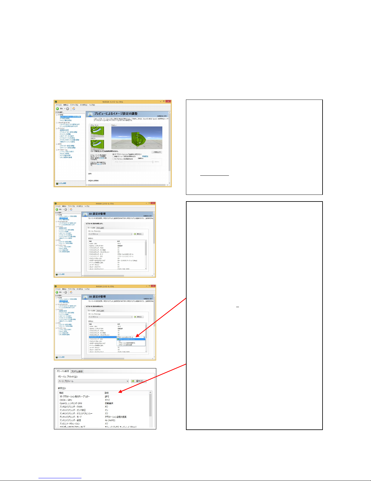
[プレビューによるイメージ設定の調整]
[3D 設定の管理]
[プレビューによるイメージ設定の調整]
それぞれの設定変更に対しての画質をプレビ
ューできます。
設定の方法は、
・ 3D アプリケーションによって自動的に決
定する(L)
・ 詳細 3D イメージ設定を使用する(U)
・ マイ プレファレンスを使用する(M)
の 3 つの設定方法があります。
[詳細設定] をクリックすることでカスタム設
定や各 3D アプリケーションに対応した設定を
行う[3D 設定]の管理をすることができます。
[3D 設定の管理]
グローバル設定のダイアログボックスにある
各機能を設定することができます。
各機能の設定方法は、変更したい機能を選択し
てプルダウンメニューから行います。
変更後は[適用(A)]をクリックして、変更内容を
反映してください。
3D アプリケーション用のディープカラーの設定
が行えます。
この機能項目はディープカラー対応モニタを
Display-Port 接続することにより表示されま
す。
Page 31

30
[PhysX 構成の設定]
※内容について以下に説明していますが、弊社としてはサポート外の機能となっています。
(Ⅱ)[ステレオスコピック 3D]
「ステレオスコピック 3D」のカテゴリ内には次の項目があります。
・ステレオスコピック 3D を設定します
・ゲームとの互換性を表示します
※内容について以下に説明していますが、弊社としてはサポート外の機能となっています。
[ステレオスコピック 3D を設定します]
[ゲームとの互換性を表示します]
[PhysX 構成の設定]
PhysX の設定をします。
[ステレオスコピック 3D を設定します]
ステレオスコピック 3D を使用すると、奥行き
距離のある 3D コンテンツを表示することがで
きます。
[ゲームとの互換性を表示します]
ステレオスコピック 3D と互換するようにゲー
ムを構成できます。
Page 32

31
(Ⅲ)[ディスプレイ]
「ディスプレイ」のカテゴリ内には次の項目があります。
・解像度の変更
・デスクトップカラー設定の調整
・ディスプレイの回転
・HDCP ステータスの表示
・デジタルオーディオの設定
・デスクトップのサイズと位置の調整
・複数のディスプレイの設定
各項目の内容について以下に説明しています。
[解像度の変更]
[デスクトップカラー設定の調整]
[ディスプレイの回転]
[解像度の変更]
使用中のディスプレイの解像度と表示色を、各デ
ィスプレイごとにスライダーで変更することが
できます。
また、リフレッシュレートの変更もすることがで
きます。
[デスクトップカラー設定の調整]
明るさ、コントラストなどのディスプレイカラ
ーの調整を、スライダーまたはグラフを使って、
各ディスプレイごとに行うことができます。
[ディスプレイの回転]
デスクトップの位置を回転させて表示するよう
にできます。
Page 33

32
[HDCP ステータスの表示]
[デジタルオーディオの設定]
[デスクトップのサイズと位置の調整]
[HDCP ステータスの表示]
HDCP に対応しているかどうかを表示します。
[デジタルオーディオの設定]
オーディオ再生用のディスプレイを選択でき
ます。
[デスクトップのサイズと位置の調整]
各スケーリングを選択できます。
Page 34

33
[複数のディスプレイの設定]
[複数のディスプレイの設定]
複数のディスプレイを使用する方法を指定で
きます。
Page 35

34
(Ⅳ)[ビデオ]
「ビデオ」のカテゴリ内には次の項目があります。
・ビデオカラー設定の調整
・ビデオイメージ設定の調整
※内容について以下に説明していますが、弊社としてはサポート外の機能となっています。
[ビデオカラー設定の調整]
[ビデオイメージ設定の調整]
[ビデオカラー設定の調整]
ビデオコンテンツの表示設定をすることができ
ます。
[NVIDIA の設定を使用(N)]をチェックした場合、
各タブ内のダイアログボックスでスライダーを
使用して微調整することができます。
[ビデオイメージ設定の調整]
ディスプレイに表示されるビデオコンテンツの
イメージ設定をすることができます。
Page 36

35
(Ⅴ)[ワークステーション]
「ワークステーション」のカテゴリ内には次の項目があります。
・システムトポロジの表示
・Mosaic の設定
・ECC 状態の変更
・GPU 使用率の管理
[システムトポロジの表示]
[Mosaic の設定]
[ECC 状態の変更]
※内容について以下に説明していますが、弊社としてはサポート外の機能となっています。
[システムトポロジの表示]
システムに接続されているディスプレイとグラ
フィックカードを表示します。
[Mosaic の設定]
Mosaic を使用すると、複数のディスプレイを 1
台のディスプレイとして扱うことが出来ます。
Mosaic 使用中はモニタの接続変更が出来ませ
ん。接続変更を行う時は、Mosaic 設定を解除し
てください。
※Mosaic を使用する場合は、同じ種類のディス
プレイを接続してください。
[ECC 状態の変更]
GPU のエラー訂正コード(ECC)状態を変更できま
す。
Page 37

36
[GPU 使用率の管理]
[GPU 使用率の管理]
パフォーマンス関連の GPU 設定がある場合に、
Maximus 構成を使用してそれらの設定を管理で
きます。
Page 38

37
グラフィックスアクセラレータを使用している際に問題が生じた場合の対処法をいくつか示します。問題が
発生した場合には、これらの対処法を順に、もしくは全てを実行してみてください。
5.1 画面が真っ暗で表示されない
5.1.1 本体装置の電源を入れると本体の電源ランプが点灯するのに全く画面が出ない
・グラフィックスアクセラレータとモニタをつなぐモニタケーブルの接続を確認してください。
・モニタの電源ケーブルがしっかり接続されているか確認してください。
・モニタの電源スイッチが入っているか確認してください。
・モニタの入力が 2 系等以上ある場合には、入力切り替えが正しいか確認してください。
・[ハードウェアのインストール]の項を参照し、再度正しく PCI-EXPRESS スロットに実装しなおしてくだ
さい。
5.1.2 起動時にWindows起動画面から切り替わるタイミングで画面表示されなくなる
・[ハードウェアのインストール]の項を参照し、再度正しく PCI-EXPRESS スロットに実装しなおしてくだ
さい。
・モニタの表示可能な解像度、リフレッシュレートから外れている可能性があります。
グラフィックスアクセラレータを下記の方法で VGA モード起動して、画面のプロパティにて正しく画面
が出るように設定を変更してください。
- Windows 7/ Windows 8/ Windows 8.1 では起動中の NEC のロゴが表示されている間に F8 キーを 1 回
押してください。詳細ブートオプションの画面に入りますので、メニューにある[低解像度ビデオ
(640×480)を有効にする]を選択し、Windows 起動後に画面のプロパティで表示される解像度・リフ
レッシュレートにモニタが対応しているか確認してください。対応していない解像度/リフレッシ
ュレートや、対応の確認が困難な場合にはより低い解像度/リフレッシュレートを設定してから、
再起動を行ってください。
・ シングルモニタで使用時に 2 つあるモニタ出力の接続を変更すると、変更前の設定で画面が出力されるた
め OS 起動時に他方の出力コネクタに画面が出る場合があります。この場合には上記の VGA モードで起動
して、画面のプロパティにて正しく画面が出力されるように設定を変更してください。
5.2 起動時にブルーバック画面で止まってしまう
・複数のディスプレイドライバをインストールした場合には、相互の影響でディスプレイドライバが正常
に動作しない場合があります。その場合には 上記[VGA モードを有効にする]方法での起動後に 3.3 項を
参照して、コントロールパネルから不必要なディスプレイドライバを削除して再起動してください。
5.3 ディスプレイドライバをインストールしても、VGAモードで起動してしまう
・ディスプレイドライバのインストールが不十分か、ファイルが壊れている可能性がありますので、3.1
項を参照しソフトウェアのインストールを再度行ってください。
・ディスプレイドライバの制御に割り込むタイプのアプリケーションソフト(Symantec 社の pcANYWHERE 等)
を使用すると、アプリケーションソフトとディスプレイドライバのインストール/更新/アンインスト
ールの手順によっては正常にディスプレイドライバが機能しない場合があります。この場合には、一旦
アプリケーションソフトをアンインストールしてから、ディスプレイドライバをインストールするよう
にしてください。
またアプリケーションソフトの取扱説明書も参照するようにしてください。
・Quadro K5200 の故障等でカード交換を実施した場合にディスプレイドライバが正しく認識できず VGA モ
ードで起動することがあります。この場合は、3.1 項を参照しソフトウェアのインストールを行ってく
ださい。
5.4 音が鳴らない
・Quadro K5200 とディスプレイを DisplayPort で直接接続した場合、音が鳴らないことがあります。
3.2 項を参照し音の出力先が正しく設定されているか確認してください。
5.トラブルシューティング
Page 39

38
5.5 十分なパフォーマンスが得られない
・ディスプレイドライバのインストールが不十分か、ファイルが壊れている可能性がありますので、3.1
項を参照しソフトウェアのインストールを再度行ってください。
・3D グラフィックスアプリケーションの対応していない画面モードを使用している場合がありますので、
画面の領域・画面の色を確認/変更してみてください。
・マウスカーソルがソフトウェア描画されている場合には、若干ですがパフォーマンスの低下が発生しま
す。大きなカーソルやカラーカーソル等に設定している場合には、ハードウェアによるマウスカーソル
描画が有効にならず、ソフトウェア描画となります。この場合には、Windows 標準のマウスカーソルを
使用するようにしてください。また[マウスのプロパティ]の[ポインタ]タブにて、[マウスの影を有効に
する]のチェックを外してください。
・ Driver の設定を次のように設定にしてください。
- Windows 7/ Windows 8/ Windows 8.1 では、4.1.3 項にある「プレビューによるイメージ設定の調
整」画面にある「初期設定に戻す」をクリックし初期設定に戻して下さい。
その後、4.1.3 項の「3D 設定の管理」を参照して垂直同期の設定を「アプリ制御」から「強制オフ」
に設定してから適用ボタンをクリックしてください。
・本製品では LSI チップ上で温度を監視して設定されたしきい値を超えると、安全性のために自動的に動
作クロック周波数を下げて、より低消費電力のモードに移行します。その場合には基本装置本体の設置
環境を確認してください。また改善しない場合にはヒートシンクファンが回転しているかどうかと、ヒ
ートシンクにホコリ等による目詰まりが無いか確認してください。
5.6 Windows 7/ Windows 8/ Windows 8.1で3Dグラフィックスアプリケーションが正しく動作しない
・ご使用の3DグラフィックスアプリケーションがWindows 7/ Windows 8/ Windows 8.1対応か否かご確認
ください。
・以下の手順により AERO 機能を OFF にしてください。
[Windows 7 の場合]
①デスクトップの右クリックメニューにある「個人設定」をクリックする。
②ベーシックテーマとハイコントラストテーマから Windows 7 ベーシックをクリックする。
[Windows 8 の場合]
Windows8 には AERO 機能がサポートされていませんので対応確認は必要ありません。
[Windows 8.1 の場合]
Windows 8.1 には AERO 機能がサポートされていませんので対応確認は必要ありません。
5.7 スタンバイから通常の表示状態に戻らない
本体 BIOS のメニューで「Advanced」→「Advanced」→「ACPI Suspend Type」を「S3」に設定している
と、スリープ状態から復帰するとき、POWER/SLEEP スイッチを押した後に画面が真っ暗な場合がありま
す。その場合は、キーボードかマウスを操作すると通常状態に戻ります。
BIOS メニューについては、搭載している本体装置により異なります。本体装置のユーザーズガイドを参
照してください。
5.8 機能制限について
システムのスタンバイ/休止について
・OpenGL を使用したグラフィックスアプリケーションをご使用中の状態では、システムのスタンバイ
/休止はご使用になれませんのでご注意ください。
モニタの接続変更について
・Mosaic 使用中はモニタの接続変更が出来ません。変更を行った時は画面表示が異常になる事があり
ます。この状態になった時は、モニタの接続を元に戻してください。
・活線挿抜によるモニタの接続変更には対応しておりません。故障の原因になりますので行わないで
下さい。
Page 40

39
6.1 外観
6.各部の名称と機能
No. 部品名
1 Quadro K5200 (グラフィックスアクセラレータ・チップ)
2 PCI-Express 外部電源コネクタ
3 PCI-Express カードエッジコネクタ
4 GDDR5-SGRAM
5 Display-Port コネクタ2
6 Display-Port コネクタ1
7 DVI-I コネクタ
8 DVI-D コネクタ
9 リテーナ
③ ④H/S下 ②
①H/S下 ⑨
⑤ ⑥ ⑦ ⑧
Page 41
40
6.2 製品仕様
製品仕様
インターフェース PCI-Express (x16 レーン対応)
グラフィックスアクセラレータ・チップ
Quadro K5200 (nVIDIA 社製)
ビデオ RAM 容量 8GB (GDDR5-SGRAM)
VGA互換機能 あり (Quadro K5200 に内蔵)
構成 PCI-Express カード 1枚
動作電源 +3.3V±5%、+12V±5%
最大消費電力 150W
寸法 350 x 127 [mm] (2 枚幅、リテーナを含む)
重量 約 940g
モニタコネクタ
Display-Port コネクタ x2 (デジタル出力)
(別売りの DP-DVI 変換コネクタにより DVI-D での出力
が可能)
DVI-I (デジタル/アナログ出力対応)
DVI-D (デジタル出力対応)
(付属の DVI-VGA 変換コネクタにより VGA 出力も可能)
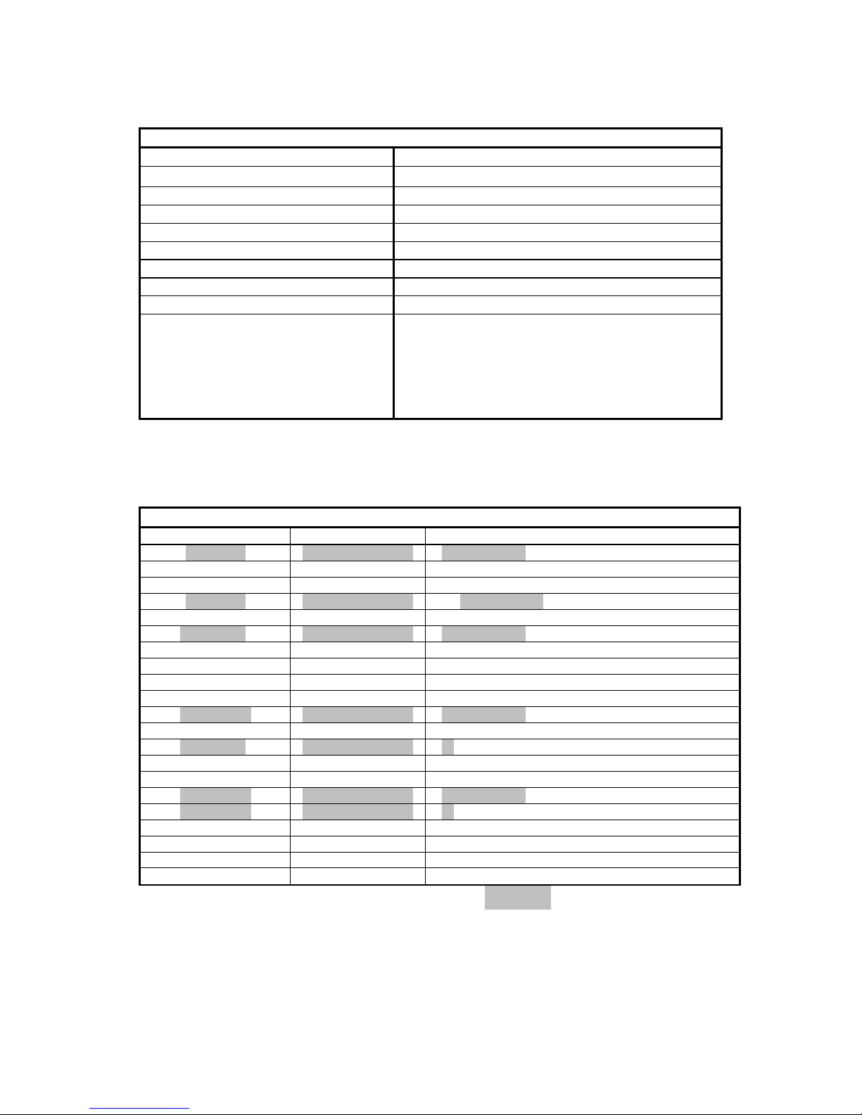
6.3 画面モード一覧
・DVI-I アナログ出力時(DVI-VGA 変換コネクタ等使用時)
アナログ接続時
画面モード一覧
解像度 色数 リフレッシュレート[Hz]
640 × 480 256,65536,1677 万色 60,70,72,75,85,100,120,140,144,150,170,200,240
720 × 480 256,65536,1677 万色 60
720 × 576 256,65536,1677 万色 60
800 × 600 256,65536,1677 万色 56,60,70,72,75,85,100,120,140,144,150,170,200,240
848 × 480 256,65536,1677 万色 60,70,72,75,85,100,120,140,144,150,170,200,240
1024 × 768 256,65536,1677 万色 60,70,72,75,85,100,120,140,144,150,170,200
1152 × 864 256,65536,1677 万色 60,70,72,75,85,100,120,140,144,150,170
1280 × 720 256,65536,1677 万色 60,70,72,75,85,100,120,140,150
1280 × 768 256,65536,1677 万色 60,70,72,75,85,100,120,140,150
1280 × 960 256,65536,1677 万色 60,70,72,75,85,100,120,140,150
1280 × 1024 256,65536,1677 万色 60,70,72,75,85,100,120,140,150
1360 × 768 256,65536,1677 万色 60,70,72,75,85,100,120,140,150
1440 × 900 256,65536,1677 万色 60
1600 × 900 256,65536,1677 万色 60,70,72,75,85,100,120
1600 × 1024 256,65536,1677 万色 60,70,72,75,85,100
1600 × 1200 256,65536,1677 万色 60,70,72,75,85,100
1680 × 1050 256,65536,1677 万色 60
1920 × 1080 256,65536,1677 万色 60,70,72,75,85
1920 × 1200 256,65536,1677 万色 60,70,72,75,85
1920 × 1440 256,65536,1677 万色 60,70,72,75,85
2048 × 1536 256,65536,1677 万色 60
※Express5800/50シリーズで動作保証しているのは網掛け部分のみです。
※接続モニタ、ディスプレイドライバのバージョンによっては、サポートする画面モードが
変わることが有ります。
Page 42

41
・デジタル出力時
デジタル(DVI、Display-Port)
画面モード一覧
解像度 色数 リフレッシュレート[Hz]
640 × 480 256,65536,1677 万色 60,72,75
800 × 600 256,65536,1677 万色 56,60,72,75
1024 × 768 256,65536,1677 万色 60,70,75
1152 × 864 256,65536,1677 万色 75
1280 × 960 256,65536,1677 万色 60,75
1280 × 1024 256,65536,1677 万色 60,75
1440 × 900 256,65536,1677 万色 60
1600 × 900 256,65536,1677 万色 60
1600 × 1024 256,65536,1677 万色 60
1600 × 1200 256,65536,1677 万色 60
1680 × 1050 256,65536,1677 万色 60
1920 × 1080 256,65536,1677 万色 60
1920 × 1200 256,65536,1677 万色 60
*2048 × 1536 256,65536,1677 万色 60
*2560 × 1440 256,65536,1677 万色 60
*2560 × 1600 256,65536,1677 万色 60
※Express5800/50シリーズで動作保証しているのは網掛け部分のみです。
※接続モニタ、ディスプレイドライバのバージョンによっては、サポートする画面モードが
変わることが有ります。
※*の付いた解像度をDVI接続で出力するには、デュアルリンク対応のモニタとケーブルで接続する必要があります。
Display-Port 接続で出力する場合、Display-Port 対応モニタに Display-Port ケーブルで接続する必要がありま
す。
注)本製品の解像度、垂直リフレッシュレートに合ったモニタをご使用ください。
モニタによっては上記画面モードをサポートしていない場合があります。
Page 43

42
6.4 モニタインターフェース・コネクタ仕様
Quadro K5200は映像出力用として2つのDisplay-Portコネクタと、1つのデジタル・アナログ統合型
Digital Visual Interface (DVI-I) とデジタル専用Digital Visual Interface (DVI-D)を装備しています。
[複数画面でのプライマリモニタの識別について]
・ DVI-I コネクタと Display-Port コネクタを使用した複数画面の場合は DVI-I コネクタへ接続してい
るモニタが、優先的にプライマリモニタとして識別されます。
・ 2 つの Display-Port コネクタを使用した複数画面の場合、Display-Port コネクタ1に接続している
モニタが優先的にプライマリモニタとして識別されます。(Display-Port コネクタへ別売りの
DP-DVI 変換コネクタを使用した DVI 接続も含みます。)
6.4.1 Display-Portコネクタ・インタフェース
Display-Port コネクタは、10 個のコンタクトから構成されるデジタル セクションを持ちます。
Display-Port インタフェースによる接続のほか、別売りの DP-DVI 変換コネクタによる DVI-D 接続も可能
となっています。
Display-Port コネクタ2 Display-Port コネクタ1 DVI-I コネクタ
DVI-D コネクタ
Page 44

43
6.4.2 DVI-Iコネクタ・インタフェース
DVI-I コネクタには、24 個(8 個 x 3 列)のコンタクトから構成されるデジタル セクション、およびアナロ
グ信号用の 5 つのコンタクトから構成されるアナログ セクションを持ちます。
また DVI-I では、DVI インタフェースによるデジタル接続のほか、添付の DVI-VGA 変換コネクタによるア
ナログ出力も可能となっています。
本製品でアナログ出力を行う場合には、添付の DVI-VGA 変換コネクタをご使用ください。
6.4.3 DP-DVI変換コネクタ
Quadro K5200 の Display-Port コネクタに、別売りの DP-DVI 変換コネクタを接続することで DVI-D 出力に
よるデジタル出力が可能になります。
(入力)
Quadro K5200
Display-Port コネクタ
(出力)
DVI-D コネクタ
モニタ
Page 45

44
6.4.4 DVI-VGA変換コネクタ
Quadro K5200 の DVI-I コネクタに DVI-VGA 変換コネクタを接続することで VGA コネクタによるアナログ出
力が可能になります。
VGA (D-sub15Pin)コネクタ・インターフェース
Dsub-15Pin コネクタのピン配置(アナログ)
ピン番号 信号名
1 赤出力
2 緑出力
3 青出力
4 モニタ ID0
5 DDC グランド
6 赤グランド
7 緑グランド
8 青グランド
9 +5V 電源
10 同期信号グランド
11 モニタ ID2
12 DDC データ
13 水平同期
14 垂直同期
15 DDC クロック
(入力)
Quadro K5200
DVI-I コネクタ
(出力)
VGA (Dsub-15Pin)
コネクタ
モニタ
Page 46

45
P
c NEC Corporation 2015
日本電気株式会社の許可なく複製・改変などを行うことはできません。
NEC Express ワークステーション
Quadro K5200
ユーザーズガイド
2015 年 3 月 1 版
日 本 電 気 株 式 会 社
東京都港区芝五丁目7番1号
TEL (03) 3454-1111 (大代表)
Page 47

NEC Express Workstation
Express5800 Series
Graphics Accelerator
Quadro K5200
User's Guide
Page 48

1
Keep this manual at hand for quick reference at any time necessary.
Be sure to read "Notes on Use" before handling this product.
Notes on Use (Be Sure to Read)
The following provides information required to use this product safely and properly.
For details of names in this section, refer to "Names and Functions of Parts" in the User's
Guide.
Follow the instructions in this User's Guide for the safe use of the product.
This User’s Guide describes hazardous parts of the workstation, possible hazards, and how
to avoid them. In this User’s Guide, "WARNING" or "CAUTION" is used to indicate a degree of
danger. These terms are defined as follows:
WARNING
Indicates there is a risk of death or serious personal injury.
CAUTION
Indicates there is a risk of burns, other personal injury, or
property damage.
Precautions and notices against hazards are indicated with one of the following three symbols.
The individual symbols are defined as follows:
Attention
This symbol indicates the presence of a hazard if
the instruction is ignored. An image in the symbol
illustrates the hazard type.
Prohibited
Action
This symbol indicates prohibited actions. An image in
or around the symbol illustrates a particular
prohibited action.
Mandatory
Action
This symbol indicates mandatory actions. An image
in the symbol illustrates a mandatory action to
avoid a particular hazard.
(Example used in the User’s Guide)
Symbol to draw attention Description of a warning Term indicating a degree of danger
WARNING
Safety Indications
Example: Do not disassemble
Example: Electric
Be sure to lock the video cable, conversion connector, and other
interfaces. Contact failure might cause a fumes or fire.
Secure the interface and power cable.
Example: Disconnect a plug
Page 49
2
ああ
Attentions
Indicates there is a risk of fire or
fumes.
Indicates the presence of electric
shock hazards.
Indicates there is a risk of personal
injury due to high temperature.
Indicates a general notice or warning
that cannot be specifically identified.
Prohibited Actions
Do not disassemble, repair, or modify
the product. Otherwise, an electric
shock or fire may be caused.
Do not use the product in the place
where water or liquid may pour.
Otherwise, an electric shock or fire
may be caused.
Do not touch the component specified by
this symbol. Otherwise, an electric
shock or burn may be caused.
Indicates a general prohibited action
that cannot be specifically
identified.
Mandatory Actions
Unplug the power cord of the product.
Otherwise, an electric shock or fire may
be caused.
Indicates a mandatory action that
cannot be specifically identified.
Make sure to follow the instruction.
Symbols used in this manual and on warning labels
Page 50

3
General
CAUTION
Keep water or foreign matter away from the workstation.
Do not let any liquid such as water or foreign materials including pins or
paper clips enter the workstation. Failure to follow this warning may cause
an electric shock, a fire, or failure of the workstation. If such things
accidentally enter the workstation, immediately turn off the power and
disconnect the power plug from the outlet. Do not disassemble the
workstation, and contact the store where you purchased the product or your
maintenance service company.
Safety Precautions ~ Be sure to read ~
WARNING
Do not use the product for services where human life may be at stake or high
reliability is required.
This product is not intended for use in medical, nuclear, aerospace, mass
transit or other applications where human life may be at stake or high
reliability is required, nor is it intended for use in controlling such
applications. We assumes no liability for any personal injury and property
damages caused by such use of this product.
Observe warnings and cautions for workstation.
Be sure to observe warnings and cautions for workstation when using this
product.
Do not use the workstation if any smoke, odor, or noise is present.
If smoke, odor, or noise is present, immediately turn off the workstation
and disconnect the power plug from the outlet, then contact the store where
you purchased the product or your maintenance service company. Using the
workstation in such conditions may cause a fire.
Page 51

4
Installation, storage, and connection
CAUTION
Do not install or store the product in any place other than specified.
Do not install the product in the following places or any place other than
specified in the User's Guide of workstation. Failure to follow this
instruction may cause a fire.
・A dusty place.
・A humid place such as near a boiler.
・A place exposed to direct sunlight.
・An unstable place.
Do not use the product in an environment where corrosive gas is present.
Do not install or use the product in a place subject to corrosive gases
including sodium chloride, sulfur dioxide, hydrogen sulfide, nitrogen
dioxide, chlorine, ammonia, or ozone. Do not install the product in an
environment that contains dust, chemicals that accelerate corrosion such
as NaCl or sulfur, or conductive materials. Failure to follow this warning
may cause the wiring on the printed board to short-circuit, leading to
fumes, fire or malfunction. If you have any questions, contact the store
where you purchased the product or a maintenance service company.
Disconnect the power plug before installing this product or
connecting/disconnecting an interface cable and power cable.
Be sure to disconnect the power plug of the workstation from a power outlet
before connecting/disconnecting this product and interface cables.
Touching any internal device of the workstation with its power cord
connected to a power source may cause an electric shock or a fire resulted
from a short circuit even if the workstation is off-powered.
Do not use any unauthorized interface cable and power cable.
Use only the interface cables and power cables specified by NEC. Locate
a proper device and connector before connecting a cable. Using an
unauthorized cable or connecting a cable to an improper destination may
cause a short circuit, resulting in a fire. Also, observe the following
notes on using and connecting an interface cable and power cable.
・Do not use any damaged cable connector.
・Do not step on the cable.
・Do not place any object on the cable.
・Do not use the workstation with loose cable connections.
・Do not use any damaged cable.
Secure the interface and this product power cable.
Be sure to lock the video cable, conversion connector, and other
interfaces. Contact failure might cause a fumes or fire.
Do not hold the interfaces cable and this product power cable when
disconnecting it.
When disconnecting a interfaces cable and this product power cable from
the device, remove the lock,hold the cable connector and pull it straight
out. Pulling the cable out by the cable portion or giving mechanical stress
to the connector could damage the cable and connector to result in an
electric shock hazard or a fire.
Page 52

5
Do not use the attached power cable for any other devices or usage.
The power cable that comes with the product is designed aiming to connect
with this product and to use with the product, and its safety has been
tested. Do not use the attached power cable for any other purpose. Doing
so may cause a fire or an electric shock.
Cleaning and Handling
WARNING
Do not disassemble, repair, or alter the product.
Never attempt to disassemble, repair, or alter the product on any occasion
except as described in this document. Failure to follow this warning may
cause not only malfunction of the product but also an electric shock or
fire.
During operation
CAUTION
Avoid contact with the product during thunderstorms.
Do not touch any part of the workstation including the cables when a
thunderstorm is approaching. Also, do not connect or disconnect any
devices. There may be a risk of electric shock from lightning strike.
CAUTION
Pay attention to hot surface.
Components including this product in the workstation are extremely hot
immediately after the workstation is powered off. Allow the surface to
cool before installing/removing.
Page 53

6
Notes sur usage (Soyez sûr de lire)
Le suivre fournit l'information a exigé pour utiliser ce produit sans risque et correctement.
Pour détails de noms dans cette section, faites référence aux "Noms et Fonctionne de Parties"
dans le Guide de l'Utilisateur.
Suivez les instructions de ce guide pour un usage en toute sécurité du poste de travail NEC Express.
Ce document décrit les parties dangereuses du poste de travail, les risques possibles, et
comment s’y prendre pour les éviter. Les composants du poste de travail présentant un risque
de danger sont indiqués avec une étiquette de mise en garde placée sur eux ou autour d’eux ou,
dans certains cas, en imprimant les avertissements sur le poste de travail même. Dans ce document
ou sur les étiquettes de mise en garde, les termes AVERTISSEMENT ou PRÉCAUTION sont utilisés
pour indiquer un degré de danger. Ces termes sont définis comme ci-après :
AVERTISSEMENT
Ce terme signale qu’il y a risque de mort ou de
blessure.
ATTENTION
Ce terme signale qu'il y a un risque de brûlures, d'autre
blessure ou de dégâts matériels.
Les précautions et notices contre les risques sont présentées avec l’un des trois symboles suivants.
Les différents symboles sont définis comme ci-après :
Attention
Ce symbole signale la présence de risque si
l'instruction reste ignorée. Une image dans le
symbole illustre le type de risque.
Actions qui
est
interdite
Ce symbole signale des actions qui sont
interdites. Une image dans le symbole illustre une
action interdite particulière.
Action
obligatoire
Ce symbole signale des actions qui sont
obligatoires. Une image dans le symbole illustre
une action obligatoire pour éviter un risque
particulier.
(Un exemple d’étiquette utilisée dans ce Guide de l’Utilisateur)
Symbole pour attire votre attention votre attention avertissement Terme indiquant un degré de danger
AVERTISSEMNT
Gardez n'importe quand ce manuel sous la main pour référence rapide nécessaire.
Soyez sûr de lire " Notes sur usage " avant de manier ce produit.
Mesures de sécurité
:
Example: Risque de
décharge
Soyez sûr de fermer à clé le câble de la vidéo, connecteur de la conversion
et d'autres interfaces.L'échec du contact peut causer un vapeurs ou feu.
Fixez l'interface et ce câble d'alimentation du produit.
Example: Disconnect a plug
Page 54

7
ああ
Attention
Ceci signale qu'il y a un risque
d’incendie ou de fumée.
Ceci signale la présence de risques de
décharge électrique.
Ceci signale la présence d'une surface ou
d'un composant réchauffé. Tout contact
avec cette surface risque de provoquer une
blessure corporelle.
Ceci signale un avis ou un avertissement
général qui ne peuvent pas être
identifiés spécifiquement.
Actions qui sont interdites
Ne démontez pas, ne réparez pas ou ne
modifiez pas le poste de travail. Si
cette précaution n’est pas observée,
une décharge électrique ou un incendie
peut être causé.
N'utilisez pas le poste de travail
dans un endroit où de l'eau ou un
liquide peut être versé. Si cette
precaution n’est pas observée, une
décharge électrique ou un incendie
peut être causée.
Ne touchez pas le composant spécifié par
ce symbole. Si cette précaution n’est
pas observée, une décharge électrique
ou une brûlure peut être causée.
Ceci signale une action interdite en
général qui ne peut pas être
identifiée spécifiquement.
Actions obligatoires
Débranchez le câble d’alimentation du
poste de travail. Si cette précaution
n’est pas observée, une décharge
électrique ou un incendie peut être
causé.
Ceci signale une action obligatoire
qui ne peut pas être identifiée
spécifiquement. Veillez à suivre
correctement l’instruction
Symboles utilisés dans ce document et sur les étiquettes
de mise en garde
Page 55

8
Généralités
ATTENTION
Éloignez la présence d’eau ou de corps étrangers du poste de travail.
Ne laissez aucun liquide tel que de l'eau ou des corps étrangers, y compris
trombones ou goupille pénétrer dans le poste de travail. Si cette observation
n’est pas respectée, une décharge électrique, un incendie ou un défaut de
fonctionnement du poste de travail peuvent se produire. Si de tels éléments
pénètrent accidentellement dans le poste de travail, interrompez
immédiatement le courant et détachez la prise d’alimentation de la prise
de sortie. Ne démontez pas le poste de travail, et contactez votre société
de service de maintenance.
Précautions de la sécurité ~Soyez sûr de lire~
AVERTISSEMEMNT
N'utilisez pas ce poste de travail pour des services pour lesquels une haute
disponibilité critique peut affecter directement les vies humaines ou pour
lesquels une fiabilité élevée est exigée.
Ce poste de travail n'est pas prévu
Ce poste de travail n'est pas prévu pour être utilisé avec des équipements
ou dispositifs de contrôle concernant les vies humaines, y compris les
appareils médicaux, équipements et installations nucléaires,
dispositifs d'aéronautique et d'espace, installations et dispositifs de
transport, ainsi que les installations et dispositifs exigeant une
fiabilité élevée. Nous n'assumons aucune responsabilité pour tout accident
ayant comme résultat une blessure, un décès, ou les dégâts matériels, si
le poste de travail a été utilisé dans les
conditions mentionnées ci-dessus.
Observez des avertissements et des prudences pour poste de travail.
Soyez sûr d'observer des avertissements et des prudences pour poste de travail
quand utiliser ce produit.
DN'utilisez pas ce poste de travail si de la fumée, une odeur ou du bruit sont
observés.
Si la fumée, une odeur ou du bruit sont observés, arrêtez immédiatement le
fonctionnement du poste de travail et détachez la prise d’alimentation de
la prise de sortie, puis entrez en contact avec le magasin où vous avez acheté
ce produit ou avec votre société du service de maintenance. L’usage de ce
poste de travail sous de telles conditions risque de provoquer un incendie.
Page 56

9
Installation, relocalisation, stockage et connexion
CAUTION
N'installez et ne rangez le poste de travail dans aucun endroit autre que ceux
spécifiés.
N'installez pas et ne rangez pas le poste de travail dans les endroits
mentionnés ci-après, ou tout endroit autre que ceux spécifiés dans ce Guide
de l’Utilisateur. Si vous ne suivez pas cette instruction, vous
risquez de provoquer un incendie.
・Endroit poussiéreux
・Endroit humide comme près d'une chaudière
・Endroit exposé à la lumière directe du soleil
・Endroit instable
N'utilisez pas le poste de travail dans un environnement où un gaz corrosif
est présent.
N'installez pas le poste de travail dans un endroit sujet aux gaz corrosifs,
y compris chlorure de sodium, anhydride sulfureux, sulfure d'hydrogène,
dioxyde d'azote, chlore, ammoniaque ou ozone. N'installez pas le poste de
travail dans un environnement qui contient de la poussière, des produits
chimiques qui accélèrent la corrosion, telle que NaCl ou soufre, ou matériaux
conducteurs. Si vous ne respectez pas cette observation, vous risquez de
provoquer un court-circuit au câblage de la carte électronique, ceci pouvant
résulter en un incendie. Si vous avez des questions à poser, veuillez entrer
en contact avec le magasin où vous avez acheté ce produit ou la société de
service de maintenance.
N'essayez pas d'installer ou d’enlever les dispositifs en option, de connecter
ou déconnecter le câble d'interface et le câble d'alimentation pendant que le
câble d’alimentation est branché à une source d’alimentation.
Assurez-vous de bien débrancher le câble d’alimentation de la prise de
courant avant d'installer/d’enlever les dispositifs en option ou de
connecter/déconnecter tout câble d'interface et le câble d'alimentation vers
le/à partir du poste de travail. Si le poste de travail est désactivé, mais
son câble d’alimentation est branché à une source d’alimentation, en
touchant un câble ou un connecteur, vous risquez de provoquer une décharge
électrique ou un incendie à la suite d'un court-circuit.
Utilisez seulement le câble d'interface spécifié.
Utilisez seulement les câbles d'interface fournis par NEC et placez
l’appareil et le connecteur appropriés avant de connecter le câble.
L’utilisation d’un câble non autorisé ou le raccordement d’un câble dans
un but incorrect risque de provoquer un court-circuit, ayant comme résultat
un incendie. En outre, observez les notes suivantes concernant l’utilisation
et le raccordement d’un câble d'interface.
・N'utilisez aucun connecteur du câble endommagé.
・Ne marchez pas sur le câble.
・Ne placez aucun objet sur le câble.
・ N’utilisez pas le poste de travail avec les jonctions de câble
desserrées.
・N’utilisez aucun câble endommagé.
Fixez l'interface et ce câble d'alimentation du produit.
Soyez sûr de fermer à clé le câble de la vidéo, connecteur de la conversion
et d'autres interfaces.
L'échec du contact peut causer un vapeurs ou feu.
Page 57

10
Ne saisissez pas câble d'interface et le câble d'alimentation lorsque vous le
déconnectez.
Lorsque vous déconnectez câble d'interface et le câble d'alimentation de
l’appareil, retirez le verrou, saisissez le connecteur du câble et tirez-le
tout droit.En tirant le câble par la partie du cable ou en appliquant une force
au connecteur, vous pouvez endommager le câble et le connecteur, avec comme
conséquence un risque de décharge électrique ou un incendie.
N’utilisez pas le câble d’alimentation fourni avec aucun autre appareil ou
pour d’autre usage.
Le câble d’alimentation fourni avec ce produit est conçu pour se connecter
à ce produit et pour utiliser avec ce même produit, et sa sécurité a été testée.
N’utilisez le câble d’alimentation fourni pour aucun autre but. Si cette
précaution n’est pas respectée, vous risquez de provoquer un incendie ou
une décharge électrique.
Nettoyage et opération avec les dispositifs internes
AVERTISSEMENT
Ne démontez pas, ne réparez pas ou ne modifiez pas le poste de travail.
N'essayez jamais de démonter, réparer ou modifier le poste de travail dans
un but autre que celui décrit dans ce document. Si vous n’observez pas cette
instruction, vous risquez de provoquer une décharge électrique ou de causer
un incendie aussi bien que des défauts de fonctionnement du poste de travail.
Durant le fonctionnement
ATTENTION
Évitez de toucher le poste de travail en cas d’orage.
Ne touchez pas une partie quelconque du poste de travail, y compris les câbles
lorsqu’un orage s'approche. En outre, ne connectez pas ou ne déconnectez
pas aucun appareil. Ceci risque de causer une décharge électrique causée par
la foudre.
ATTENTION
Faites bien attention à la surface chaude.
Juste après que le poste de travail ait été mis hors tension, ses composants
internes, tels que lecteurs de disque dur, sont très réchauffés. Laissez les
composants internes du poste de travail se refroidir avant
d'installer/d’enlever n'importe quel composant.
Page 58

11
Warning label are attached on or near the components with potential hazards to draw attention
from users to potential hazards involved in handling the product.(Do not remove or black out
this label and keep it clean). If label is peels off or stained, contact your sales
representative.
●The paste of the warning label
If the caution label is provided, attach it to the rear face of workstation.
53Xi
55Xa 56Xg/56Xg-E
Warning labels
Label location
HOT SURFACE
SURFACE CHAUDE
Label location
HOT SURFACE
SURFACE CHAUDE
Page 59

12
Les étiquettes de mise en garde sont collées sur les composants ou à proximité de ces composants
qui présentent des risques de danger pour attirer votre attention sur les risques possibles
de danger, lorsque vous opérez le poste de travail. (N'enlevez pas ou ne noircissez pas cette
étiquette et maintenez-la bien propre). Si aucune étiquette n'est attachée ou est imprimée
sur le poste de travail, ou s'il y a une étiquette se détachant ou qui est souillée, veuillez
entrer en contact avec votre représentant de commerce.
●La pâte de l'étiquette d'avertissement
Si l'étiquette de mise en garde est fournie, l'attacher à la face arrière du poste de travail.
53Xi
55Xa 56Xg/56Xg-E
Étiquettes de mise en garde
l'emplacement de l'étiquette
HOT SURFACE
SURFACE CHAUDE
l'emplacement de l'étiquette
HOT SURFACE
SURFACE CHAUDE
Page 60

13
Thank you for purchasing our graphics accelerator Quadro K5200.
The Quadro K5200 is designed exclusively for CAD or OpenGL application related to image
display that works on NEC Express5800 Series workstation. The Quadro K5200 is a graphics
accelerator card that allows rapid graphics drawing by onboard graphics accelerator chip
Quadro K5200. The Quadro K5200 can work on Microsoft Windows 7, Windows 8 and
Microsoft Windows 8.1.
Read this User's Guide thoroughly to fully understand handling of the Quadro K5200 and
appreciate its functions to the maximum extent.
(1) This manual describes how to use the graphics accelerator Quadro K5200.
For any other devices, refer to the relevant manual.
(2) No part of this manual may be reproduced in any form without the prior written permission
of NEC Corporation.
(3) The contents of this manual may be revised without prior notice.
(4) The contents of this manual shall not be copied or altered without the prior written
permission of NEC Corporation.
(5) Keep this manual in a safe place for quick reference at anytime necessary.
(6) All efforts have been made to ensure the accuracy of all information in this manual. If
you notice any part unclear, incorrect, or omitted in this manual, contact the service
representative where you purchased this product.
(7) NEC assumes no liability arising from the use of this product, nor any liability for
incidental or consequential damages arising from the use of this manual regardless of
Item (6).
Microsoft, Windows, Windows 7, Windows 8, Windows 8.1, MS– DOS are registered trademarks
or trademarks of Microsoft Corporation in the United States and other countries.
NVIDIA, Quadro are registered trademarks or trademarks of NVIDIA Corporation in the United
States and other countries.
OpenGL is a trademark of Silicon Graphics, Inc.
All other product, brand, or trade names used in this publication are the trademarks or
registered trademarks of their respective trademark owners.
Windows Operating Systems are referred to as follows.
Notations in this document Official names of Windows
Windows 7
Windows 7 Professional(32-bit)
Windows 7 Professional(64-bit)
Windows 8
Windows 8 Pro(32-bit)
Windows 8 Pro(64-bit)
Windows 8.1 Windows 8.1 Pro(64-bit)
Preface
Notes:
Trademarks
Abbreviations of Operating Systems
Page 61

14
If at the time of shipment separately, comes with a warranty on this product. It confirms
it on the content, please keep it in a safe place.
In the case of when the workstation is
built shipment, please refer to the warranty and User's Guide of the workstation.
For the product of its warranty period expired, contact your sales agent or service
representative.
・N E C assumes no liability for malfunction of the product resulted from using the third-party
workstation, devices and interface cables not authorized by NEC.
Information is provided also on the following web site:
http://www.nec.com/
The display driver newer than that stored in DVD-ROM provided with the product may have
been uploaded to this site. Check and use it as needed.
Observe the following precautions when you transfer (or sell) the product to a third party.
・Graphics Accelerator
When transferring (or selling) the product to a third party, be sure to provide this User's
Guide along with the product.
・Provided Software
- When transferring (or selling) the product to a third party, be sure to provide all
the software, and the transferor must not retain any backup copies.
- Transfer requirements listed in "Software License Agreement" that comes with each
software must be satisfied.
Dispose of this product according to all national laws and regulations.
Warranty
Information Service
Transfer to a Third Party
Disposal
Page 62

15
FCC Statement
This device complies with Part 15 of the FCC Rules. Operation is subject to the following two conditions:
(1) this device may not cause harmful interference, and (2) this device must accept any interference received,
including interference that may cause undesired operation.
Industry Canada Class B Emission Compliance Statement/
Avis de conformité à la réglementation d'Industrie Canada:
CAN ICES-3(B)/NMB-3(B)
KC Mark , KC Statement
KCC-REM-NVA-P2081
기 종 별 사 용 자 안 내 문
B 급 기기
(가정용 방송통신기자재)
이 기기는 가정용(B 급) 전자파적합기기로서 주로 가정에서
사용하는 것을 목적으로 하며, 모든 지역에서 사용할 수
있습니다.
Chinese RoHS
部件名称
有毒有害物质或元素
铅
(Pb)
汞
(Hg)
镉
(Cd)
六价铬
(Cr(Ⅵ))
多溴联苯
(PBB)
多溴二苯醚
(PBDE)
螺丝 × ○ ○ ○ ○ ○
本表格依据 SJ/T 11364 的規定編制。
○:表示该有害物质在该部件所有均质材料中的含量均在 GB/T 26572 规定的限量要求以下。
×:表示该有害物质至少在该部件的某一均质材料中的含量超出 GB/T 26572 规定的限量要求。
Regulatory Notices
Page 63

16
Contents
Safety Indications ................................................................................................................................................ 1
Symbols used in this manual and on warning labels ....................................................................................... 2
Safety Precautions ~ Be sure to read ~ .............................................................................................. 3
Notes sur usage (Soyez sûr de lire) .................................................................................................................... 6
Mesures de sécurité .............................................................................................................................................. 6
Précautions de la sécurité ~Soyez sûr de lire~ ...................................................................................... 8
Warning labels ............................................................................................................................................................ 11
Étiquettes de mise en garde ............................................................................................................................... 12
Preface ....................................................................................................................................................................... 13
Notes: .......................................................................................................................................................................... 13
Trademarks ................................................................................................................................................................ 13
Abbreviations of Operating Systems ....................................................................................................... 13
Warranty ..................................................................................................................................................................... 14
Information Service ........................................................................................................................................... 14
Transfer to a Third Party ............................................................................................................................ 14
Disposal ..................................................................................................................................................................... 14
Regulatory Notices ............................................................................................................................................. 15
Before Installation ........................................................................................................................................... 17
Checking Accessories .................................................................... 17
Checking Operating Environment .......................................................... 17
1. Installation .................................................................................................................................................... 18
2. Installing Hardware .................................................................................................................................... 19
2.1 Precautions on handling the card .................................................... 19
2.2 Installing the Card ................................................................. 20
2.3 Removing the Card ................................................................... 25
3. Installation/Uninstallation of Software .................................................................................... 26
3.1 Installing Display Driver ........................................................... 26
3.2 Change the sound driver output destination ........................................... 28
3.3 Uninstallation of Display Driver .................................................... 30
4 Configuration .................................................................................................................................................... 32
4.1 Configuration on Windows 7 / Windows 8/ Windows 8.1 .................................. 32
5.Troubleshooting ............................................................................................................................................. 44
5.1 Nothing is displayed on black solid screen. .......................................... 44
5.2 The system halts at startup with the blue background screen. ......................... 44
5.3 The system starts with VGA mode even the display driver has been installed. .......... 44
5.4 Performance is insufficient ......................................................... 44
5.5 Performance is insufficient ......................................................... 45
5.6 3D graphics application does not work normally on Windows 7/ Windows 8/ Windows 8.1 .. 45
5.7 Fail to return to normal state from standby state. ................................... 45
5.8 Restrictions on Feature ............................................................. 45
6.Names and Functions of Parts .............................................................................................................. 46
6.1 External View ....................................................................... 46
6.2 Product Specification ............................................................... 47
6.3 Display Modes ....................................................................... 47
6.4 Specification of Monitor Interface Connector ......................................... 49
Page 64

17
Checking Accessories
Refer to the "Getting Started!" that comes with the product. Make sure that you have all accessories
and inspect them. If any accessory is missing or damaged, contact your sales representative.
Checking Operating Environment
Workstation
The Quadro K5200 works on NEC Express5800 series workstation that contains the PCI-Express slot.
Ask your sales representative for applicable workstation model, and other requirements.
If any additional board that is not verified by NEC is installed together with this product,
the operation of the product is not guaranteed.
Operating System
The Quadro K5200 works on a computer on which Windows 7 / Windows 8 / Windows 8.1 runs normally.
Monitor
Use the monitor that satisfies resolution and refresh rate of this product. The resolution and
refresh rate may differ depending on monitor type.
Before Installation
Page 65

18
This section describes how to install hardware and software. Installation procedure depends on whether
the other graphics accelerator is installed in your system or not. Follow the steps below to install
them appropriately to your system.
Even if Quadro K5200 is already installed in your system, you need to install the display driver.
(1)If any graphics accelerator other than Quadro K5200 is installed, be sure to uninstall other
display driver before installing Quadro K5200.
When uninstalling display driver, restart the system and make sure that the system starts
normally.
※To uninstall the display driver, follow the steps below:
[Windows 7]
①
Select[Control Panel] → [Programs] → [Uninstall Programs]. (In Classic View, select [Control
Panel] → [Programs and Features].)
②
Select a driver you want to uninstall from the list, and double– click it to uninstall.
③
Restart Windows.
※
The Windows INBOX display driver may be installed after the restart. If restarting the system
is requested, restart the system according to the on– screen message.
[Windows 8]
①
Select[Control Panel] → [Uninstall Programs] (In Classic View, select [Control Panel] →
[Programs and Features].)
②
Select a driver you want to uninstall from the list, and double– click it to uninstall.
③
Restart Windows.
※ The Windows INBOX display driver may be installed after the restart. If restarting the system
is requested, restart the system according to the on– screen message.
[Windows 8.1]
①
Select[Control Panel] → [Uninstall Programs] (In Classic View, select [Control Panel] →
[Programs and Features].)
②
Select a driver you want to uninstall from the list, and double– click it to uninstall.
③
Restart Windows.
※ The Windows INBOX display driver may be installed after the restart. If restarting the system
is requested, restart the system according to the on– screen message.
(2)Make sure that the workstation is powered off, unplug the power cord, and install the Quadro
K5200 in the workstation. See "2. Installing Hardware" for installation procedure.
(3)Installing Windows (If Windows is already installed, you may skip this step).
(4)Install the display driver according to "3.1 Installing Display Driver".
Take the steps above to install hardware and software.
1. Installation
Page 66

19
2.1 Precautions on handling the card
・ It is recommended to ask your sales representative to install this product in your workstation.
Refer to the User's Guide of workstation when installing this product.
・ The electronic components used in this product may be damaged by electrostatic discharge. Take
an appropriate anti-static measures (e.g., by grounding a part of your body) when handling this
product. Do not touch the component side and connector directly with your hand. Hold the rear
panel or edge of the card.
Wear an antistatic gloves for injury prevention when handling this product.
・ Before installing/removing the card in/from the workstation or connecting/disconnecting cables
to/from the product, be sure to power off the workstation and peripheral devices and unplug
the power cable from power outlet.
・ If you drop the conductive material such as a screw or a clip in the workstation and it is hard
to take it out, consult with your service representative or your maintenance service company.
・ To avoid bad influence by radio wave, turn off the cell phone or PHS when handling the product.
CAUTION
Unplug the power cord
If the workstation is running, quit all the applications, power off the workstation
and peripheral devices, and then unplug the power cord from power outlet.
Pay attention to hot surface
Immediately after the workstation is turned off, its internal components are extremely
hot. Make sure that they are fully cooled down before installing the card.
2. Installing Hardware
Page 67

20
2.2 Installing the Card
(1) After making sure that workstation and peripheral devices are turned off, unplug the power
cord of the workstation.
(2) Remove the top cover from the chassis according to the User's Guide of the workstation.
(3) Remove the slot cover (fixing screw or fixing jig) from the PCI-Express (x16) slot, and remove
the slot cover or PCI-Express card.
※The PCI-Express slot of workstation may have card locking mechanism in addition to fixing
screw/fixing jig.
※Pay strict attention to remove the double-width card because the locking mechanism cannot
be seen directly. Applying excess power may cause damage to the lock lever.
(4) Insert the PCI-Express card edge connector of Quadro K5200 into PCI-Express x16 slot on the
workstation so that the card can be connected firmly.
About retainer
If you want to connect a Quadro K5200 to 55Xa, connect into the workstation after you install
a retainer to QuadroK5200.(refer to the figure1-3.)
If you want to connect a 56Xg / 56Xg-E and 53Xi, attachment of the retainer to the Quadro
K5200 is unnecessary, because there is no fixed rail(see Figure 2) to the workstation.
Figure1
CAUTION
Pay attention to hot surface
Immediately after the workstation is turned off, its internal components and
PCI-EXPRESS card are extremely hot. Make sure that they are fully cooled down before
removing the card.
Retainer
Page 68

21
Figure2
Figure3
※If the DIMM slots are located near the PCI-Express x16 slot, make sure that the lock levers
of DIMM are surely raised.
※If the PCI-Express x16 slot has locking lever, connect the card carefully not to damage the
locking lever.
CAUTION
Do not apply an excess force
If it is hard to connect the card, remove it once, and then connect it again. Applying
excess force to card may cause a damage to the card.
Do not apply force to the components on the card (e.g., heat sink and capacitor) when
connecting the card.
DIMM locking lever
PCI-Express x16 slot locking lever
Insert the PCI-Express card edge
connector into PCI-Express x16 slot on
the workstation so that the card can be
connected firmly.
[55Xa]
Install a retainer to QuadroK5200,
insert the card into PCI-Express x16
slot.
Page 69
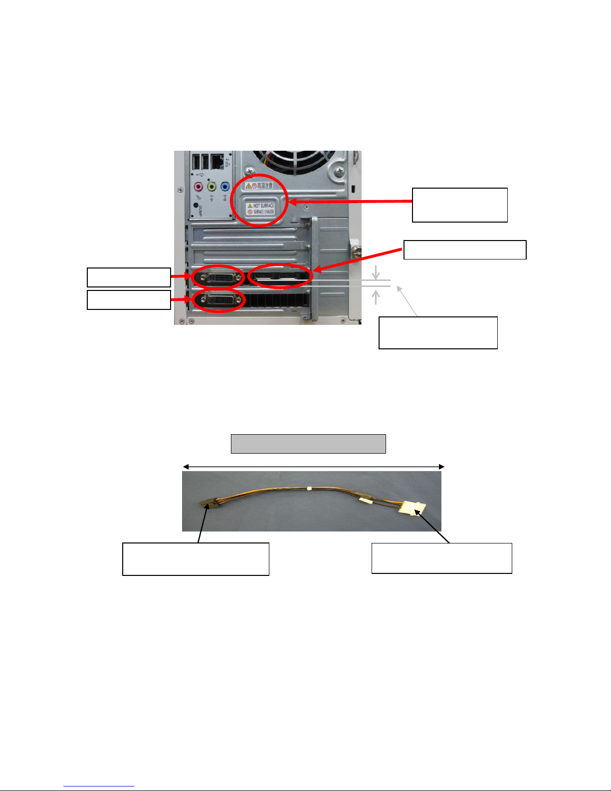
22
(5) After making sure that the card is firmly inserted, secure the Quadro K5200 with the screws
or fixing jig you have removed in earlier steps.
Make sure that you can see the Display-Port connector and DVI-I connector is parallel to
the slot of the workstation.
※ If the caution label is provided, attach it to the rear face of workstation.
Labeling position of the main unit, please refer to the chapter of the warning label.
(6) Connect the proper connector from power supply unit to the PCI-Express external power
connector (6-pin) on Quadro K5200 card. If the proper connector is not provided with the
power supply unit of the workstation, connect the 6-pin side of PCI-Express external power
cable, and connect a power cable of workstation to 4-pin connector.
Label location
(Hot Surface)
Display-Port connector
DVI-I connector
DVI-D connector
The connector and the
slot are parallel
PCI-Express external power cable
Connect to PCI-Express external
power connector on Quadro K5200
Connect with power cable of
workstation
Page 70

23
If the number of power cables provided with workstation is insufficient, use the power branch
cable.
※If the cable length is too long, bundle it so that the connector does not contact with metal
part, or the cable is not caught by fan or metal plate.
※Route the PCI-Express external power cable and SATA cable for connecting with HDD or ODD,
as shown in the figure below.
Connecting the power cable is different by the workstation. The reference to the User's
Guide for the workstation.
Connect the male connector to
power connector on workstation.
The female connector can be used
similarly as an ordinary power
connector.
Power branch cable
PCI Route the PCI-Express external
power cable so that it passes over the
Quadro K5200.
Route the SATA cable for connecting
with HDD or ODD so that it passes below
the retainer of Quadro K5200, and
connect it with the device.
Page 71

24
(7) Connecting monitor cable
Quadro K5200 has four connectors: one DVI-I connector, one DVI– D connector, and two
Display-Port connectors. Connect tha card with monitor in the following procedure.
When connecting with analog monitor (CRT monitor, LCD monitor)
Only the DVI-I connector can connect with analog monitor.
Connect DVI to VGA connector to DVI-I connector on Quadro K5200 card, and secure it to
workstation with fixing screws. Then, connect a video cable to VGA connector of conversion
connector, and secure the cable with fixing screw.
When connecting with digital monitor
① DVI-compliant LCD monitor
Connect a video cable of monitor to DVI-I connector or DVI– D connector of Quadro K5200
card, and firmly secure the cable with fixing screws.
Or, connect a separately priced DP to DVI conversion connector to Display-Port connector
on Quadro K5200 card and firmly secure the cable with locking mechanism. Then, connect
a video cable of monitor to another end of DVI-D connector on DP to DVI conversion
connector, and firmly secure the video cable with fixing screw.
② Display-Port-compliant LCD monitor
Connect a video cable of monitor to Display-Port connector on Quadro K5200 card.
※To use the monitor in multiple display mode, connect the primary and secondary monitors according
to “6.4 Specification of Monitor Interface Connector”.
※Connecting monitor cables to all the four connectors allows output on four displays.
(8) Install the top cover of workstation you have removed in Step (2), and connect power cable
of workstation.
This completes hardware installation.
※If the beep sound is heard at power on, the Quadro K5200 card is not recognized. In this
case, insert the Quadro K5200 card into PCI-EXPRESS again.
※If that is the Quadro K5200 implementation two, if you have implemented in combination with
Tesla K20, please make sure that it is correctly recognized by the following procedure. If
the Quadro K5200 card is not recognized, the card is sure is surely plugged all the way to
the PCI-EXPRESS slot, please reconnect again PCI-EXPRESS slot.
[Windows 7]
① Right-click on the [Computer] through the Start menu, click on the [Manage].
②
Open the [Computer Management].Click on the [Device Maneger] from the left side of the window.
③
Click [▷ ] to the left the [Display adapters] item from the Device Maneger list.
④
Whether there is a display of Quadro K5200, [?] And [!] But to confirm that you are not being
displayed.
[Windows 8/ Windows 8.1]
①
Right-click on Start menu, select [Device Maneger] to open Device Maneger.
②
Open the [Device Manager]. Click [▷ ] to the left the [Display adapters] item from the list.
③
Whether there is a display of Quadro K5200, [?] And [!] But to confirm that you are not being
displayed.
Page 72

25
2.3 Removing the Card
※Before removing the card, make sure how to release the locking mechanism of PCI-Express slot
(see Figure 1).
※If you remove the card with the PCI-Express slot being locked, the locking mechanism may be
damaged.
(1) After making sure that workstation and peripheral devices are turned off, unplug the power
cord of workstation.
(2) Disconnect the monitor from workstation.
(3) Remove the top cover from workstation according to the User's Guide of workstation.
(4) Disconnect PCI-Express external power cable from PCI-Express external power connector on
Quadro K5200.
(5) Remove the screw or fixing jig from rear bracket of Quadro K5200.
(6) Remove the Quadro K5200 from PCI-Express slot while pushing the locking part (see Figure
1) toward the direction of arrow mark.
Note)Pull the Quadro K5200 straight up while pushing the locking part (see Figure 1) to unlock
the retainer and fixing rail so that the Quadro K5200 can keep parallelism, and then
remove the card from PCI-Express slot by the 55Xa.
Figure 1 Figure 2
Figure 3
(7) Install the back slot cover to PCI-Express(x16) slot, and secure it with the screw or fixing
jig.
(8) Install the top cover of workstation.
Locking part
[55Xa]
Retainer of Quadro K5200 and
fixing rail of workstation
Page 73

26
3.1 Installing Display Driver
(1) Prepare the "3D Graphics Accelerator nVIDIA Display Driver" DVD– ROM disk that comes with
Quadro K5200.
(2) Start the OS, and login the system with an account having an Administrator right.
※The PnP feature of OS detects Quadro K5200, and the "Found New Hardware Wizard" may start.
Click the [Cancel] button to close the wizard.
(3) Insert the DVD– ROM into the optical disk drive.
(4) Windows7
From the Start menu, select [All Programs] → [Accessories] → [Explorer].
Windows8
Right-click on Start menu, select [All Programs] at lower right → [Explorer].
(5) Double-Click the following file to start installer of display driver:
- Windows 7 32– bit: [Setup.exe] under the [Win7] folder
- Windows 7 64– bit: [Setup.exe] under the [Win7_64] folder
- Windows 8 32– bit: [Setup.exe] under the [Win8] folder
- Windows 8 64– bit: [Setup.exe] under the [Win8_64] folder
- Windows 8.1 64– bit: [Setup.exe] under the [Win81_64] folder
※Be sure to select a proper file appropriate an OS you are using. If the selected driver
is inappropriate to your OS, the installer will fail to run.
3. Installation/Uninstallation of Software
Page 74

27
(6) Installing on Windows 7 / Windows 8/ Windows 8.1
※When you click [Setup.exe] on Windows 7 / Windows 8/ Windows 8.1, a message to ask permission
for user account control will be displayed. Click [Continue] or [Yes] to proceed with
installation.
(7) This completes installation of display driver.
This completes installation of display driver.
When installation of display driver is finished, setup screen resolution, color depth, and refresh
rate according to “Chapter 4 Configuration”.
If it does not work properly, please go restarting again.
Click the [AGREE AND CONTINUE]
Select an Installation options.
Make sure that [Express (Recommended)] is
checked, and click the [NEXT] button.
Click the [CLOSE] button.
If restarting the system is requested, restart
the system according to the on-screen message.
Page 75
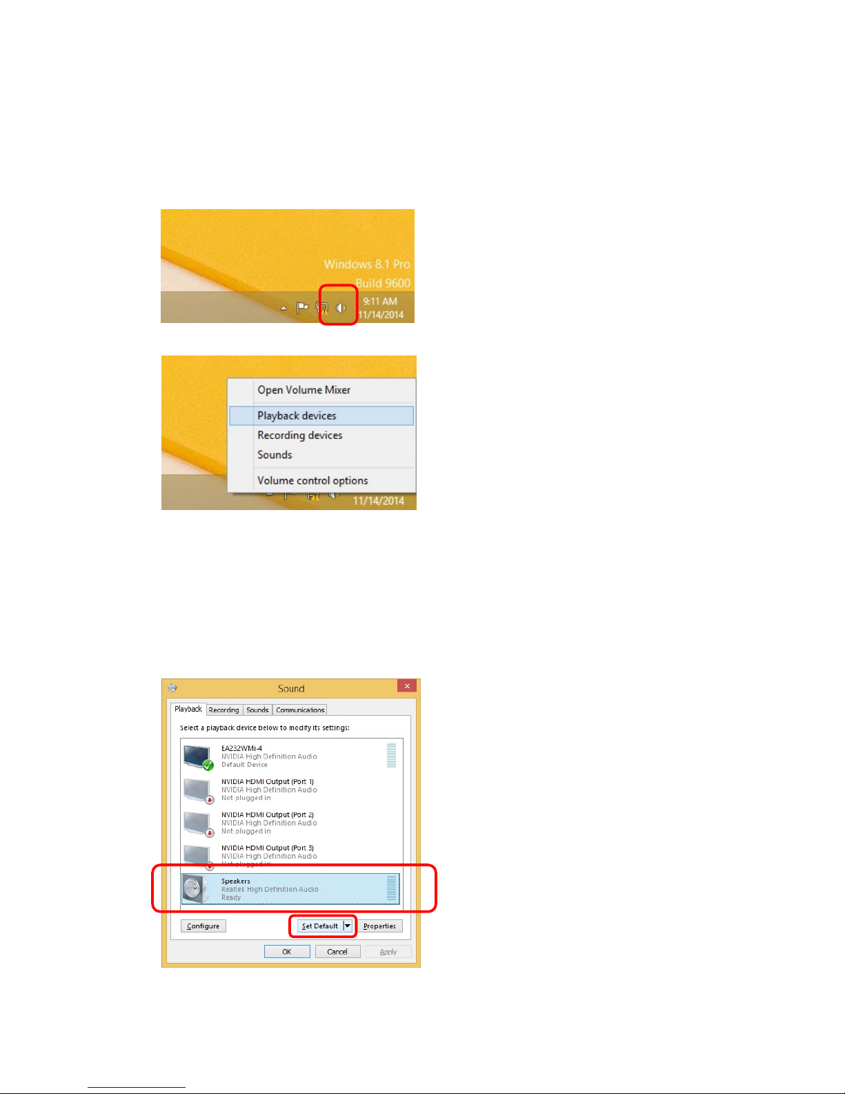
28
3.2 Change the sound driver output destination
If connecting DP port of display with DP port of Quadro K4200 directly, the sound is output from
the display that is connected. At this time, since no sound is heard from the workstation speaker,
when you issue the sound from the workstation speaker, change setting in the following procedure.
If you want to output the sound from the display is set to display the output destination.
(1) Right-click the Sound icon at the bottom of screen (indicated by red circle).
(2) Click [Playback devices(P)].
(3) The window as shown below appears.
Check the current settings, select the device you want to output to the change of the output
destination.
Example)
If the default device is [NVIDIA High Definition Audio], select [Realtek High Definition
Audio], and click [Set Default].
・[NVIDIA High Definition Audio] is the output from the DisplayPort of the connected display.
・Speakers(*) is the output from the workstation.
(*)[Realtek High Definition Audio] is name different by the workstation.
Page 76

29
(4) Make sure that [Speakers] is assigned to default device, and click [OK].
Be should hear sound through the speakers of the workstation.
Page 77

30
3.3 Uninstallation of Display Driver
Take the steps below to uninstall the display driver.
(1) Start the OS, and login the system with an account having an Administrator right.
(2) On Windows 7, click the [Start] → [Control Panel] → [Uninstall a program] in order.
On Windows 8, right-click on the start menu, select [All Programs] → [Control Panel] →
[Uninstall a program] in order.
On Windows 8.1, left-click on the start menu, select [Control Panel] → [Uninstall a program]
in order.
※The HDAudio driver needs to be uninstalled separately. Uninstall it in the same procedure as
display driver.
Click the [UNINSTALL] button to continue
uninstallation.
Double–click [NVIDIA Graphics Driver
xxx.xx] on program list to start
uninstallation.
※ The driver version which corresponds to
OS is shown.
※ If a message to ask permission for user
account control is displayed. Click
[Continue] or [Yes] to proceed with
uninstallation.
Click the [RESTART NOW] to restart the
system.
Page 78

31
(3) Upon completion of uninstallation, you will be requested to restart the system. Click [Yes]
to restart the system to reflect the results of uninstallation.
This completes uninstallation of display driver.
Page 79

32
This section describes screen settings and configuration on [NVIDIA Control Panel].
4.1 Configuration on Windows 7 / Windows 8/ Windows 8.1
This section describes how to configure Quadro K5200 using the [Screen Resolution] window.
※ On Windows 7/Windows 8/Windows 8.1, you need to logon the system with "Administrator".
※ Take the steps below to open the [Screen Resolution] window.
・Click [Control Panel] → [Adjust Screen Resolution] in order.
・Right– click on desktop, and select [Screen Resolution (C)] from the right– click menu.
4.1.1 Setting multiple displays
Quadro K5200 allows you to use four displays independently.
Take the steps below to specify multiple displays.
On this menu, you can specify multiple displays and display area (resolution).
If you select [Advanced settings] to open the Properties of [Quadro K5200], you can specify
the refresh rate and Color Depth on the [Monitor] tab.
4 Configuration
① Select any of the following from the
[Multiple displays] pull–down menu.
・[Duplicate desktop on 1 and 2]
Displays in clone mode.
・[Duplicate desktop on 1 and 3]
Displays in clone mode.
・[Duplicate desktop on 1 and 4]
Displays in clone mode.
・[Extend desktop to this display]
This option can be specified if
the currently selected display is
not used.
To extend the screen, select a target
display, and select [Extend desktop to
this display].
② Click [Apply].
Page 80

33
4.1.2 Specifying Screen Resolution, Color Depth, and Refresh Rate
・Screen resolution
Use the [Screen Resolution] window to change the resolution.
・About Screen resolution
The larger screen resolution can display many information at a time, however, on the contrary,
the pixel size become small and a display may become hard to view. In addition, since the maximum
resolution that can be displayed depends on the performance of the monitor to be connected. Specify
the resolution appropriate to your monitor according to the instruction manual of your monitor.
CRT monitor: Select an appropriate resolution according to the table shown below.
Monitor type Recommended resolution
15-inch CRT 640x480 to 1024x768 pixel
17-inch CRT 1024x768 to 1280x1024 pixel
22-inch CRT 1280x1024 to 1600x1200 pixel
LCD monitor: Recommended resolution is predetermined. Specify the recommended resolution
according to the instruction manual of your monitor.
Select a display you want to change its
resolution, and select a resolution
appropriately by moving the slider, and
click the [Apply] button.
A pop–up window shown above may appear
depending on the selected resolution.
Make sure that the resolution is
appropriate, and click [Retain change].
Page 81

34
・Color Depth
Specify the color depth on the [Generic PnP monitor and NVIDIA Quadro K5200 Properties] that
appears by clicking [Advanced settings] in [Screen resolution]. Click the [Monitor] tab, select
a desired color from pull– down menu of [Color], and click [OK].
※To select 8– bit (256 colors), select [Modes] in [Adapters] tab.
・About color Depth
Quadro K5200 supports display colors of 256, 65536, and TrueColor. The difference of display colors
means the difference of color depth that can be displayed simultaneously. The consumption of video
memory depends on the number of display colors. Specify the color palette appropriately according
to the below table.
Number of
display colors
BPP
(Bit Per Pixel)
Color Depth that can be displayed
simultaneously
Purpose
256 8 Can display 256 colors among 16,777,216
colors.
The business application etc. which do
not need a multicolor display
65536 16 Can display 65,536 colors simultaneously.
(Green: 64 grades, Red, Blue: 32 grades
each)
The game and CAD/CG application etc.
which require high speed performance.
TrueColor 32 Can display 16,777,216 colors
simultaneously.
(24 bits are used for color information
among 32 bits (32BPP)).
Red, Green, Blue: 256 grades each
CAD/CG application, etc.
・Refresh rate
Specify the refresh rate on the [Generic PnP monitor and NVIDIA Quadro K5200 Properties] that
appears by clicking [Advanced settings] in [Screen resolution]. Click the [Monitor] tab, select
a desired refresh rate from the pull-down menu of [Refresh Rate], and click [Apply].
・About refresh rate
A refresh rate means the number of renewal of screen performed for 1 second. If a refresh rate
is high, the flicker of a screen can be suppressed. However, note that the higher the refresh
rate, the lower the drawing performance.
The LCD monitor does not require high refresh rate compared with a CRT monitor because its
after-image persists for a long time.
The maximum of the refresh rate depends on monitors to be connected.
※You can use [NVIDIA Control Panel] to specify multiple displays, screen resolution, color depth,
and refresh rate. See the next section for details.
Page 82

35
4.1.3 NVIDIA Control Panel
・Opening [NVIDIA Control Panel]
Right– click anywhere on desktop to open the menu. Click [NVIDIA Control Panel] to select it.
・On the [NVIDIA Control Panel], use the main task pane and the navigation tree pane to setup drivers.
・The main task pane is used to setup the graphics driver. From the next time, the Control Panel
opens the page that was viewed last.
・In the navigation tree pane, the tasks available on Control Panel are displayed in tree structure.
The following categories are available:
・3D Settings - Configure the 3D performance and the picture quality.
・Display - Change resolution and setup multiple displays, and others.
・Stereoscopic3D - Configure the stereoscopic 3D (not supported).
・Video - Configure the video output (not supported).
・Workstation - Display the displays and graphics card being connected.
The task menus of NVIDIA Control Panel are as follows:
Navigation tree pane
Main task pane
Page 83

36
(Ⅰ)[3D Settings]
The following items are contained in [3D Settings] category:
・ Adjust image settings with preview
・ Manage 3D settings
・ Set PhysX Configuration
The details of each item are described below:
[Adjust image settings with preview]
[Manage 3D Settings]
[Adjust image settings with preview]
You can preview the image as settings are
changed.
There are three setting method as follows:
・ Let the 3D application decode
・ Use the advanced 3D image settings
・ Use my preference emphasizing
Clicking [Use the advanced 3D image
settings] takes you to [Manage 3D Settings]
page. On the [Manage 3D Settings] page, you
can change the global 3D settings and create
overrides for specific programs.
[Manage 3D Settings]
You can specify the features in Global
Settings dialog box.
Select a desired feature and select a value
from pull-down menu.
After changed, click [Apply] to reflect the
new setting.
You can specify the deep color for 3D
application.
This feature is displayed when a monitor that
supports deep colors is connected to
Display-Port.
Page 84

37
[Set PhysX Configuration]
※Explanations are given here, however, this feature is not supported by NEC.
(Ⅱ)[Display]
The following items are contained in [Display] category:
・Change resolution
・Adjust desktop color settings
・Rotate display
・View HDCP status
・Set up digital audio
・Adjust desktop size and position
・Set up multiple displays
The details of each item are described below:
[Change Resolution]
[Set PhysX Configuration]
Set PhysX Configuration.
[Change Resolution]
You can change the resolution and color depth
of each display.
You can also change the refresh rate.
Page 85

38
[Adjust Desktop Color Settings]
[Rotate Display]
[View HDCP Status]
[Adjust Desktop Color Settings]
You can adjust desktop color settings
including brightness and contrast for each
display. Use the slider or a graph to set the
display color.
[View HDCP Status]
Displays whether the display supports HDCP
or not.
[Rotate Display]
You can change the orientation of the desktop.
Page 86

39
[Set Up Digital Audio]
[Adjust Desktop Size and Position]
[Set Up Multiple Displays]
[Adjust Desktop Size and Position]
You can select a scaling mode.
[Set Up Multiple Displays]
You can specify how you would like to use
multiple displays.
[Set Up Digital Audio]
You can select displays for audio playback.
Page 87

40
(Ⅲ)[Stereoscopic 3D]
The following items are contained in [Stereoscopic 3D] category:
・Set up stereoscopic 3D
・View compatibility with games
※Explanations are given here, however, this feature is not supported by NEC.
[Set Up Stereoscopic 3D]
[View Compatibility With Games]
[Set Up Stereoscopic 3D]
Stereoscopic 3D allows you to view 3D
content with visible depth.
[View Compatibility With Games]
You can configure your games to work well
with stereoscopic 3D.
Page 88

41
(Ⅳ)[Video]
The following items are contained in [Video] category:
・Adjust video color settings
・Adjust video image settings
※Explanations are given here, however, this feature is not supported by NEC.
[Adjust video color settings]
[Adjust Video Image Settings]
[Adjust video color settings]
You can fine tune the color settings for video
content on your display.
If you check to [With the NVIDIA settings],
you can fine tune the color settings in each
tab by using the slider.
[Adjust Video Image Settings]
You can set an image for video content on your
display.
Page 89

42
(Ⅴ)[Workstation]
The following items are contained in [Workstation] category:
・View system topology
・Set up Mosaic
・Change ECC state
・Manage GPU Utilization
[View System Topology]
[Set Up Mosaic]
[Change ECC State]
※Explanations are given here, however, this feature is not supported by NEC.
[View System Topology]
Shows the displays and graphics cards
connected with the system.
[Set Up Mosaic]
Mosaic allows you to use multiple displays as
a single display.
During Mosaic is configured, you cannot change
connection of monitor. To change monitor
connection, cancel Mosaic configuration.
※If you use the Mosaic, connect the same type
of displays.
[Change ECC State]
You can change the Error Correction Code (ECC)
state for GPUs.
Page 90
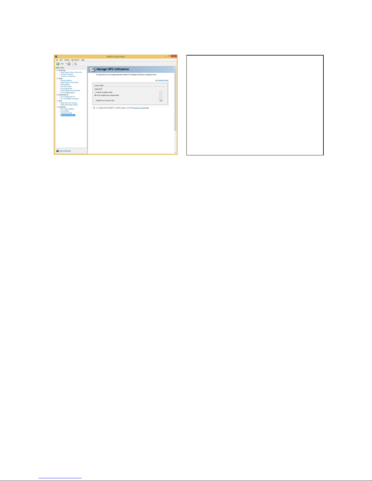
43
[Manage GPU Utilization]
[Manage GPU Utilization]
This page allows you to manage performance
related GPU settings with Maximus
configuration if any.
Page 91

44
If any trouble occurs while you are using the graphics accelerator, see the following to solve the
problem. Take countermeasures described below one by one in order, or try all measures.
5.1 Nothing is displayed on black solid screen.
5.1.1 The Power LED goes on, but the screen does not appear.
・Confirm the connection status of monitor cable between graphics accelerator and monitor.
・Confirm that power cable of monitor is firmly connected.
・Confirm that the power switch of monitor is turned on.
・If the monitor has two or more input port, confirm that the proper port is selected.
・Install the graphics accelerator again in PCI-EXPRESS slot according to [Installing Hardware].
5.1.2 The screen display disappears when switching from Windows Startup screen.
・Install the graphics accelerator again in PCI-EXPRESS slot according to [Installing Hardware].
・The specified resolution and/or refresh rate may be out of available range of monitor.
Start the graphics accelerator in VGA mode, and change settings on Screen Properties, as shown
below.
- On Windows 7 / Windows 8/ Windows 8.1, press the <F8> key once while the NEC logo is on the
screen. On the Advanced Boot Option screen, select [Enable low resolution video (640×480)],
confirm that your monitor satisfies the resolution and refresh rate displayed on Screen
Properties. If the monitor does not satisfy them, or it is difficult to confirm, specify the
lower resolution/refresh rate, and restart the system.
・ If connection is changed between the two monitor output ports in single monitor mode, the screen
displays according to the settings before changing connection. Thus, the screen may appear on
another output connector at OS startup. In this case, start the graphics accelerator in VGA mode,
and change settings on Screen Properties.
5.2 The system halts at startup with the blue background screen.
・If two or more display drivers are installed, they may fail to work normally due to mutual influence.
In this case, start the graphics accelerator with [Enable VGA mode] Describe above, remove the
unnecessary driver from Control Panel according to Section 3.3, and restart the system.
5.3 The system starts with VGA mode even the display driver has been installed.
・Installation of display driver is incorrect, or the file may be destroyed. Install software again
according to Section 3.1.
・If an application that interrupts control of display driver (e.g., pcANYWHERE made by Symantec )
is used, the display driver may fail to work depending on the order of
installation/update/uninstallation of application software and display driver. In this case,
uninstall an application software, then install a display driver.
See also the Instruction Manual of application software.
・If the Quadro K5200 card is replaced due to failure, the system may start with VGA mode because
the display driver is not detected correctly. In this case, install the software again according
to Section 3.1.
5.4 Performance is insufficient
・If connecting DP port of display with DP port of Quadro K5200 directly, sound is inaudible from
the workstation speaker. Check the output destination setting of sound in according to Section
3.2.
5.Troubleshooting
Page 92

45
5.5 Performance is insufficient
・Installation of display driver is incorrect, or the file may be destroyed. Install software again
according to Section 3.1.
・The specified screen mode may not support 3D graphics application. Confirm or modify the drawing
area and color.
・If the mouse cursor is drawn by software, the performance may be lowered slightly. If the large
cursor or color cursor is specified, the drawing of mouse cursor is not performed by hardware,
but by software. In this case, use the Windows standard mouse cursor. In addition, disable
(uncheck) [Enable shadow of mouse] in [Pointer] tab of [Mouse properties].
・ Setup the driver as follows:
- On Windows 7 / Windows 8 / Windows 8.1, click [Restore Defaults] on [Adjust Image Settings
With Preview], as shown in Section 4.1.3.
Then, change setting of vertical synchronization from [Application-controlled] to [Forced
off], and click the [Apply] button. See Section 4.1.3 [Manage 3D Settings].
・The Quadro K5200 monitors temperature on LSI chip. If the temperature rises beyond the specified
threshold, the card automatically lowers the operating clock speed for safety, and moves to low
power consumption mode. In this case, check the installation environment of workstation. If the
problem persists, check if fan of heat sink is normally rotating, and heat sink is not clogged
with dusts.
5.6 3D graphics application does not work normally on Windows 7/ Windows 8/ Windows 8.1
・Confirm if the 3D graphics application you are using is applicable to Windows 7/ Windows 8/
Windows 8.1.
・Turn off the AERO feature in the following procedure:
[Windows 7]
①Click [My Preference] from the right-click menu on desktop.
②Click [Windows 7 Basic] from Basic Theme and High-Contract Theme.
[Windows 8]
Windows 8 does not support AERO feature.
[Windows 8.1]
Windows 8.1 does not support AERO feature.
5.7 Fail to return to normal state from standby state.
If "S3" is specified for [Advanced] → [Advanced] → [ACPI Suspend Type] on BIOS SETUP menu of
workstation, the screen may become solid black when POWER/SLEEP switch is pressed to return from
the sleep mode. In this case, manipulate keyboard or mouse to return to normal state.
5.8 Restrictions on Feature
Standby/Hibernation of System
・While using a graphics application using OpenGL, the system cannot enter Standby/Hibernation
mode.
Change connection of monitor
・Connection of monitor cannot be changed while Mosaic is being used. If changed, the screen
display may become abnormal. In this case, restore the original connection.
・Changing connection of monitor during power-on state is not supported. Doing so may cause
a failure.
Page 93

46
6.1 External View
6.Names and Functions of Parts
No. Component name
1 Quadro K5200 (Graphics Accelerator Chip)
2 PCI-Express External Power Supply Connector
3 PCI-Express Card Edge Connector
4 GDDR5-SGRAM
5 Display-Port Connector 2
6 Display-Port Connector 1
7 DVI-I Connector
8 DVI-D Connector
9 Retainer
③ ④Under H/S ②
①Under H/S ⑨
⑤ ⑥ ⑦ ⑧
Page 94

47
6.2 Product Specification
Product Specification
Interface PCI-Express (x16 lane supported)
Graphics Accelerator Chip Quadro K5200 (Made by nVIDIA)
Video RAM Capacity 8GB (GDDR5-SGRAM)
Compatibility with VGA Interface Provided (Embedded in Quadro K5200)
Composition One PCI-Express card
Operating Voltage +3.3V±5%、+12V±5%
Maximum Power Consumption 150W
Board Size 350 x 127 [mm] (Double width, retainer included)
Weight Approx. 940 g
Monitor connector
Display-Port connector x2 (Digital output)
(Connecting a separately priced DP to DVI connector
allows an output by DVI– D interface.)
DVI-I (Integrated digital/analog output)
(Connecting a provided DVI to VGA connector allows
a VGA output.)
DVI-D (Digital output)
6.3 Display Modes
・DVI-I analog output (when DVI to VGA connector is used)
Display modes in analog connection
Resolution Color Depth Refresh rate [Hz]
640 × 480 256,65536,1677 million colors 60,70,72,75,85,100,120,140,144,150,170,200,240
720 × 480 256,65536,1677 million colors 60
720 × 576 256,65536,1677 million colors 60
800 × 600 256,65536,1677 million colors 56,60,70,72,75,85,100,120,140,144,150,170,200,240
848 × 480 256,65536,1677 million colors 60,70,72,75,85,100,120,140,144,150,170,200,240
1024 × 768 256,65536,1677 million colors 60,70,72,75,85,100,120,140,144,150,170,200
1152 × 864 256,65536,1677 million colors 60,70,72,75,85,100,120,140,144,150,170
1280 × 720 256,65536,1677 million colors 60,70,72,75,85,100,120,140,150
1280 × 768 256,65536,1677 million colors 60,70,72,75,85,100,120,140,150
1280 × 960 256,65536,1677 million colors 60,70,72,75,85,100,120,140,150
1280 × 1024 256,65536,1677 million colors 60,70,72,75,85,100,120,140,150
1360 × 768 256,65536,1677 million colors 60,70,72,75,85,100,120,140,150
1440 × 900 256,65536,1677 million colors 60
1600 × 900 256,65536,1677 million colors 60,70,72,75,85,100,120
1600 × 1024 256,65536,1677 million colors 60,70,72,75,85,100
1600 × 1200 256,65536,1677 million colors 60,70,72,75,85,100
1680 × 1050 256,65536,1677 million colors 60
1920 × 1080 256,65536,1677 million colors 60,70,72,75,85
1920 × 1200 256,65536,1677 million colors 60,70,72,75,85
1920 × 1440 256,65536,1677 million colors 60,70,72,75,85
2048 × 1536 256,65536,1677 million colors 60
※ Only the shaded values (resolution, color depth, and refresh rate) are verified by
Express5800/50 series workstation.
※The supported display modes may differ depending on the connected monitor type and the version
of display driver.
Page 95

48
・Digital output
Display modes in digital connection (DVI, Display-Port)
Resolution Color Depth Refresh rate [Hz]
640 × 480 256,65536,1677 million colors 60,72,75
800 × 600 256,65536,1677 million colors 56,60,72,75
1024 × 768 256,65536,1677 million colors 60,70,75
1152 × 864 256,65536,1677 million colors 75
1280 × 960 256,65536,1677 million colors 60,75
1280 × 1024 256,65536,1677 million colors 60,75
1440 × 900 256,65536,1677 million colors 60
1600 × 900 256,65536,1677 million colors 60
1600 × 1024 256,65536,1677 million colors 60
1600 × 1200 256,65536,1677 million colors 60
1680 × 1050 256,65536,1677 million colors 60
1920 × 1080 256,65536,1677 million colors 60
1920 × 1200 256,65536,1677 million colors 60
*2048 × 1536 256,65536,1677 million colors 60
*2560 × 1440 256,65536,1677 million colors 60
*2560 × 1600 256,65536,1677 million colors 60
※ Only the shaded values (resolution, color depth, and refresh rate) are verified by
Express5800/50 series workstation.
※The supported display modes may differ depending on the connected monitor type and the version
of display driver.
※To output the resolution marked with an asterisk (*) by DVI connection, you need to connect
a monitor that supports dual-link mode. To output by Display-Port connection, you need to
connect a monitor that supports Display-Port with Display-Port cable.
Note)Use the monitor of its resolution and vertical refresh rate meets those of this product.
Some monitors may not support the display mode shown above.
Page 96

49
6.4 Specification of Monitor Interface Connector
Quadro K5200 has two Display– Port connectors, one integrated Digital Visual Interface (DVI-I)
connector, and one Digital Visual Interface (DVI-D) connector for image output.
[Identification of primary monitor in multiple displays mode]
・ If monitors are connected to DVI-I connector and Display-Port connector, the monitor connected
to DVI-I connector is determined as primary monitor.
・ If two Display-Port connectors are used for multiple displays, the monitor connected to
Display-Port connector 1 is determined as primary monitor (including DVI connection using
the separately priced DP to DVI Connector).
6.4.1 Display-Port Connector Interface
Display-Port connector has a digital section composed of 10 contacts.
DVI–D connection using the separately priced DP to DVI Connector can also be used in addition to
connection by Display-Port interface.
Display-Port connector2 Display-Port connector1 DVI-I connector
DVI-D connector
Page 97

50
6.4.2 DVI-I Connector Interface
DVI-I connector has a digital section composed of 24 contacts (8 contacts by 3 rows) and an analog
section composed of 5 contacts.
DVI-I connector can output analog signals by connecting a provided DVI to VGA connector in addition
to digital connection by DVI interface.
Use the provided DVI to VGA connector to output an analog signal by this board.
6.4.3 DP to DVI Connector
Connecting a separately priced DP to DVI connector to Display-Port connector on Quadro K5200 allows
digital signal output by DVI–D.
(Input)
Quadro K5200
Display-Port connector
(Output)
DVI-D connector
Monitor
Page 98

51
6.4.4 DVIto VGA Connector
Connecting a DVI to VGA connector to DVI-I connector on Quadro K5200 allows VGA connector to output
an analog signal.
VGA (D-sub15Pin) connector interface
Pin layout of Dsub– 15Pin connector (analog)
Pin No. Signal name
1 Red output
2 Green output
3 Blue output
4 Monitor ID0
5 DDC Ground
6 Red Ground
7 Green Ground
8 Blue Ground
9 +5V Power
10 SYN Ground
11 Monitor ID2
12 DDC Data
13 Horizontal Synchronization
14 Vertical Synchronization
15 DDC Clock
(Input)
Quadro K5200
DVI-I connector
(Output)
VGA (Dsub-15Pin)
connector
Monitor
Page 99

52
P
c NEC Corporation 2015
The contents of this manual shall not be copied or altered without
the prior written permission of NEC Corporation.
NEC Express Workstation
Quadro K5200
User's Guide
March 2015, First Edition
NEC Corporation
 Loading...