

Page 1
PlasmaSync™ Multimedia Monitor
MODEL PX-42M2A
PX-42M2G
SERVICE MANUAL
Better Service
PART No. 399910943
Better Reputation
Better Profit
SAFETY CAUTION:
Before servicing this chassis, it is important that the service
technician read and follow the “Safety Precautions” and “Product
Safety Notice” in this Service Manual.
WARNING:
SHOCK HAZARD - Use an isolation transformer when servicing.
Page 2

CONTENTS
SAFETY PRECAUTIONS .................................................................................................................................. 2-1
USERS MANUAL............................................................................................................................................... 3-1
TROUBLE SHOOTING ...................................................................................................................................... 4-1
METHOD OF ADJUSTMENTS .......................................................................................................................... 5-1
CIRCUIT DESCRIPTION ................................................................................................................................... 6-1
METHOD OF DISASSEMBLY ........................................................................................................................... 7-1
DISASSEMBLY.................................................................................................................................................. 8-1
METHOD OF WIRING ....................................................................................................................................... 9-1
PACKAGING.................................................................................................................................................... 10-1
REPLACEMENT PART LIST ........................................................................................................................... 11-1
CONNECTION DIAGRAMS............................................................................................................................. 12-1
BLOCK DIAGRAM ........................................................................................................................................... 13-1
SCHEMATIC DIAGRAMS................................................................................................................................ 14-1
VI/O PWB (PWC-4213B) ............................................................................................................................ 14-1
ANALOG PWB (PWC-4214)....................................................................................................................... 14-3
VIDEO PWB (PWC-4213A) ...................................................................................................................... 14-15
AUDIO PWB (PWC-4216A) ...................................................................................................................... 14-20
SOUND PWB (PWC-4216B) .................................................................................................................... 14-23
POWER PWB (PWC-4216G) ................................................................................................................... 14-25
CTL PWB (PWC-4216F)........................................................................................................................... 14-26
VOL PWB (PWC-4216C) .......................................................................................................................... 14-27
R TERMINAL PWB (PWC-4216E)............................................................................................................ 14-28
L TERMINAL PWB (PWC-4216D) ............................................................................................................ 14-29
CAUTION
In transporting the product, be sure to use the specified box. If the product does not
have the specified stand, attach the stand, then pack the project. Packing the product
without the specified stand and transporting it could cause a product failure.
1-1
Page 3
SAFETY PRECAUTIONS
CAUTION
RISK OF ELECTRIC SHOCK
DO NOT OPEN
CAUTION: TO REDUCE THE RISK OF ELECTRIC SHOCK, DO NOT OPEN TOP COVER. NO USER-SERVICEABLE
PARTS INSIDE. REFER SERVICING TO QUALIFIED SERVICE PERSONNEL.
This symbol warns the user that uninsulated voltage within the unit may have
sufficient magnitude to cause electric
shock. Therefore, it is dangerous to make
any kind of contact with any part inside of
this unit.
This symbol alerts the user that important
literature concerning the operation and
maintenance of this unit has been
included.
Therefore, it should be read carefully in
order to avoid any problems.
ATTENTION
RISQUE D'ELECTROCUTION
NE PAS OUVRIR
ATTENTION: POUR EVITER LES RISQUES D' ELECTROCUTION, NE PAS ENLEVER LE CONVERCLE SUPERIEUR. AUCUN
DES ELEMENTS INTERNES NE DOIT ETRE REPARE PAR L'UTILISATEUR. NE CONFIER L' ENTRETIEN QU'A UN
PERSONNEL QUALIFIE.
L'éclair fléché dans un triangle équilatéral est
destiné à avertir l'utilisateur de la présence,
dans l'appareil, d'une zone non-isolée soumise
à une haute tension dont l'intensité est suffisante pour constituer un risque d'électrocution.
Le point d'exclamation dans un triangle équilatéral est destiné à attirer l' attention de l'utilisateur sur la présence d'informations de
founctionnement et d'entretien importantes dans
la brochure accompagnant l'appareil.
WARNING
HEATSINK MAY BE ENERGIZED.
TEST BEFORE TOUCHING.
2-1
Page 4
SAFETY PRECAUTIONS
1. Before returning an instrument to the customer, al-
ways make a safety check of the entire instrument, in-
cluding, but not limited to, the following items.
a. Be sure that no built-in protective devices are
defective and/or have been defeated during
servicing. (1) Protective shields are provided on
this chassis to protect both the technician and
the customer. Correctly replace all missing protective shields, including any removed for servicing convenience. (2) When reinstalling the
chassis and/or other assembly in the cabinet, be
sure to put back in place all protective devices,
including,but not limited to, nonmetallic control
knobs,insulating fishpapers,adjustment and
compartment covers/shields, and isolation resistor/capacitor networks. Do not operate this
instrument or permit it to be operated without all protective devices correctly installed
and functioning.
b. Be sure that there are no cabinet openings
through which an adult or child might be able to
insert their fingers and contact a hazardous voltage. Such opening include,but are not limited to,
(1) spacing between the picture tube and the
cabinet mask, (2) excessively wide cabinet ventilation slots, and (3) an improperly fitted and/or
incorrectly secured cabinet back cover.
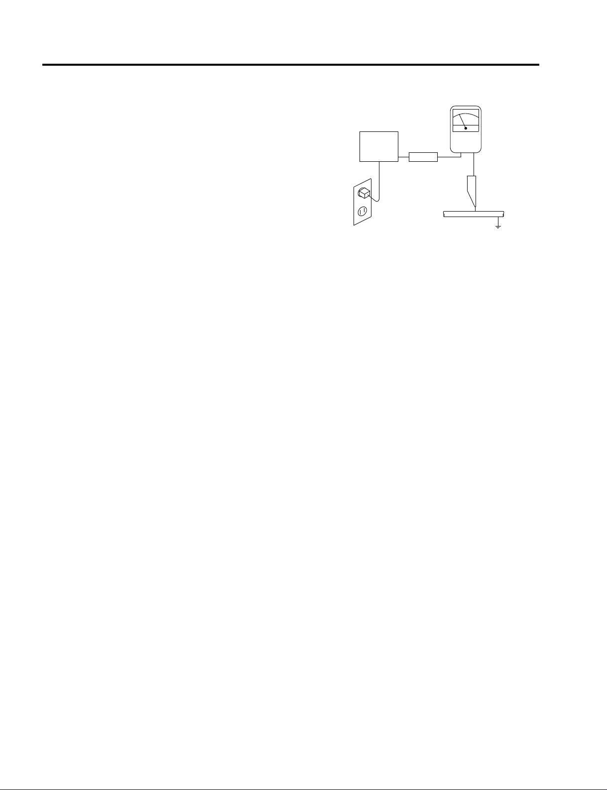
c. Leakage Current Hot Check — With the instru-
ment completely reassembled,plug the AC line
cord directly into a 120V AC outlet (PX-42M2G :
240V AC outlet). (Do not use an isolation transformer during this test.) Use a leakage current
tester or a metering system that complies with
American National Standards Institutes (ANSI)
C101.1 Leakage Current for Appliances and Underwriters Laboratories(UL) 1950. With the instrument AC switch first in the ON position and
then in the OFF position, measure from a
known earth ground (metal waterpipe,
conduit,etc.) to all exposed metal parts of the
instrument(antennas, handle bracket, metal
cabinet, screwheads, metallic overlays, control
shafts,etc.), especially any exposed metal parts
that offer an electrical return path to the chassis.
Any current measured must not exceed 3.5
milliamp. Reverse the instrument power cord
plug in the outlet and repeat test.ANY MEA-
SUREMENTS NOT WITHIN THE LIMITS
SPECIFIED HEREIN INDICATE A POTENTIAL SHOCK HAZARD THAT MUST BE
ELIMINATED BEFORE RETURNING THE INSTRUMENT TO THE CUSTOMER.
AC Leakage Test
(READING SHOULD
NOT BE ABOVE
DEVICE
UNDER
TEST
TEST ALL
EXPOSED METAL
SURFACES
3-WIRE CORD
ALSO TEST WITH
PLUG REVERSED
(USING AC ADAPTER
PLUG AS REQUIRED)
LEAKAGE
CURRENT
TESTER
+–
3.5 mA)
EARTH
GROUND
2. Read and comply with all caution and safety-related
notes on or inside the Monitor cabinet, on the Projection Monitor chassis, or on the picture tube.
3. Design Alteration Warning — Do not alter or add
to the mechanical or electrical design of this unit.
Design alterations and additions, including, but not
limited to, circuit modifications and the addition of
the items such as auxiliary audio and/or video output connections might alter the safety characteristics of this Monitor and create a hazard to the user.
Any design alterations or additions will void the
manufacturer's warranty and will make you,the
servicer,responsible for personal injury or property
damage resulting therefrom.
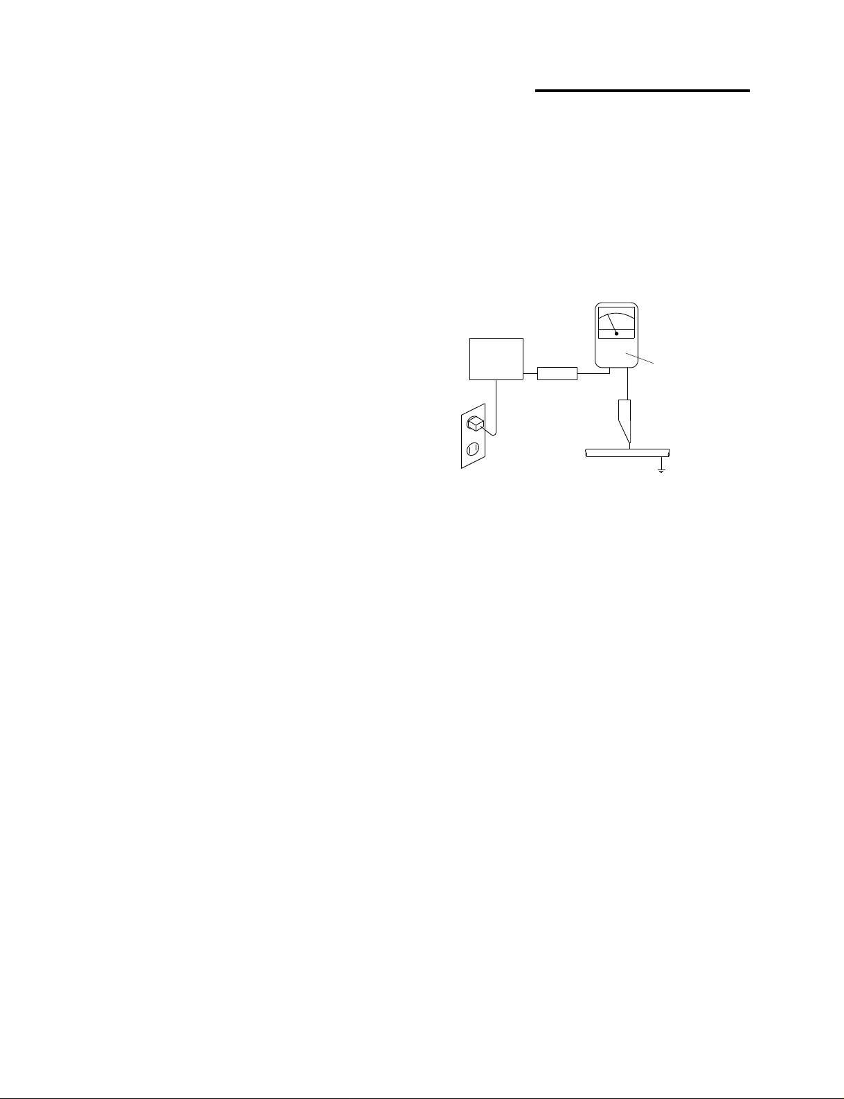
4. Hot Chassis Warning — a. Some MultiSync Monitor
chassis are electrically connected directly to one
conductor of the AC power cord and may be safely
serviced without an isolation transformer only if the
AC power plug is inserted so that the chassis is
connected to the ground side of the AC power
source. To confirm that the AC power plug is inserted correctly, with an AC voltmeter measure between the chassis and a known earth ground. If a
voltage reading in excess of 1.0V is obtained, remove and reinsert the AC power plug in the opposite polarity and again measure the voltage potential between the chassis and a known earth ground.
b. Some Projection Monitor chassis normally have
85V AC (RMS), between chassis and earth ground
regardless of the AC plug polarity. These chassis
can be safely serviced only with an isolation transformer inserted in the power line between the receiver and the AC power source, for both personnel
and test equipment protection. c. Some Projection
Monitor chassis have a secondary ground systems
in addition to the main chassis ground. This secondary ground system is not isolated from the AC
power line. The two ground system are electrically
separated by insulating material that must not be
defeated or altered.
2-2
Page 5

5. Observe original lead dress. Take extra care to
assure correct lead dress in the following areas:
a. near sharp edges, b. near thermally hot parts—
be sure that leads and components do not touch
thermally hot parts, c. the AC supply, d. high voltage, and e. antenna wiring. Always inspect in all
areas for pinched, out-of-place, or frayed wiring. Do
not change spacing between components, and between components and the printed-circuit board.
Check AC power cord for damage.
6. Components,parts, and/or wiring that appear to
have overheated or are otherwise damaged should
be replaced with components, parts, or wiring that
meet original specifications. Additionally,determine
the cause of overheating and/or damage and, if
necessary, take corrective action to remove any
potential safety hazard.
7. PRODUCT SAFETY NOTICE —Many MultiSync
Monitor electrical and mechanical parts have spe-
cial safety-related characteristics some of which
are often not evident from visual inspection, nor
can the protection they give necessarily be obtained by replacing them with components rated
for higher voltage, wattage, etc. Parts that have
special safety characteristics are identified in this
service data by shading with a mark on schematics and by shading or a mark in the parts list. Use
of a substitute replacement part that does not have
the same safety characteristics as the recommended replacement part in this service data parts
list might create shock, fire, and/or other hazards.
SAFETY PRECAUTIONS
2-3
Page 6
PRECAUTIONS DE SECURITE
1. Avant de remettre un appareil à un client, faire
toujours d'abord un examen de sécurité de
l'appareil en entier comprenant, mais ne s'y limitant
pas les points cités ci-dessous:
a. Vérifier qu' aucun des dispositifs de protection ne
soit défectueux ou n' ait été endommagé pendant
les travaux.
(1) Les volets protecteurs sur ce châssis ont été
montés pour protéger aussi bien le technicien
que le client. Remplacer correctement tous les
volets protecteurs manquants, aussi bien que
ceux qui ont pu être enlevés pour la commodité
des travaux.
(2) Quand vous remettez le châssis ou d'autres
assemblages ensemble dans le coffret, vérifier
qu' ont été remis à leur place tous les dispositifs
de protection, comprenant mais ne s' y limitant
point, les boutons de contrôle non-métalliques,
les feuilles d'isolation, les couverture/volets de
l'ajustement et du compartiment, et l'isolation des
réseaux résistance/condensateur. Ne pas
travailler sur cet appareil ni permettre qu'y
soit effectué un travail sans que tous les
dispositifs de protection n' y soient
correctement installés fonctionnants.
b. Bien vérifier qu'il n'y ait aucune ouverture sur le
coffret qui ne puisse permettre à un adulte ou à
un enfant d'y faire pénétrer ses doigts et attraper
une décharge électrique.
De telles ouvertures comprendraient sans pour
autant s'y limiter (1) l'espace entre le tube à images et le coffret de l'eppareil, (2) les espaces
excessivement ouverts pour la ventilation et (3) la
couverture arrière du coffret improprement fixée
ou incorrectement protegée.
c. Vérification de courant de fuite
L'appareil ayant été complètement réassemblé,
brancher-le à une prise de courant de 120V (PX-42M2G
: 240V). (Ne pas se servir d'un transformateur
d'isolation pendant ce test). Se servir d'un
vérificateur de courant d'excitation ou d'un
système de mesure conforme aux normes ANSI
(American National Standards Institute) C101.1
Leakage Current for Appliances et U. L (Underwriters Laboratories) 1950. Le bouton de
l'appareil en position "Marche" et ensuite en position "Arrêt", mesurer à partir d'une prise de terre
(métallique tuyauterie, conduite, etc...) à toutes
les pièces métalliques de l'appareil exposées
(antennes, poignet métalliques, coffren
métallique, tête des vis, surfaces métalliques,
traits de contrôle, etc.) surtout à toutes les pièces
métalliques exposées qui peuvent reconduire le
courant au châssis. En aucun cas, la mesure du
2-4
courant ne doit dépasser 3.5 milliamp. Inverser la
fiche de courant de l'appareil dans la prise et
répéter le test. Tout mesurage ne s'arrêtant
pas aux limites spécifiées icicomporte un risque de décharge électrique dangereux, qui
doit être éliminé, avant que l'appareil ne soit
remis au client.
EXAMEN DE COURANT
D'EXCITATION
(LA MESURE DU COURANT
NE DOIT PAS DEPASSER
3.5 MILLIAMP)
DISPOSIT IF
SOUS
L ' EXAMEN
EXAMINER TOUTES
LES PIECES METALLIQUES
DEL' APPAREIL EXPOSEE
3-CORDES DE FIL
EXAMINER AVEC
LA FICHE DE COURANT
INVERSEE
(SE SERVIR DE LA FICHE DE COURANT
DE L' A DAPTATEUR COMME DEMANDEE)
+–
VERIFICATEUR
DE CORANT
DE FUITE
PRISE DE TERRE
2. Lire et respecter toutes les mises en garde et notes
de sécurité à l'intérieur ou à l'extérieur du coffret du
rétro-projecteur, sur le châssis du rétro-projecteur
ou sur le tube à images.
3. Mise en garde contre la modification du dessin
Ne pas modifier ni ajouter à la pièce mécanique ou
électrique du modèle. Des modifications ou additions, comportant, mais ne s'y limitant pas, des
modifications des circuits et l'addition d'éléments
tels que des auxilliairs audio et/ou des
branchements pour la prise de vidéo, pourrait
éprouver la sécurité de ce rétro-projecteur et créer
un risque pour l'utilisateur. Tout changement ou ad-
dition accomplie annulera la garantie du fabricant et
va rendre votre service d'entretien, responsable des
dommages corporels ou de biens en résultant.
4. Mise en garde contre le châssis sous tension
a. Certains châssis de rétro-projecteur sont
électriquement reliés à un conducteur du fil de
courant et ainsi peuvent ne comporter aucun risque sans un transformateur d'isolation seulement
si la prise de courant est branchée, de manière
que le châssis est relié à la prise de terre de la
source de courant. Pour s'assurer que la prise de
courant est correctement insérée, relever les
mesures avec un voltmètre de courant entre le
châssis et un point de prise de terre bien connu.
Si le voltage indiqué est supérieur à 1,0V,
débrancher et reinsérer la prise de courant dans
la polarité contraire et une fois de plus remesurer
le voltage potentiel entre le câssis et la prise de
terre.
Page 7

PRECAUTIONS DE SECURITE
b. Certains châssis de moniteur ont habituellement
85V (RMS) entre le châssis et la prise de terre, en
fonction de la polarité de la prise de courant. Ces
châssis peuvent ne comporter aucun risque
seulement avec un transformateur d'isolation
inséré dans la ligne de puissance située entre de
rétro-projecteur et la source d'électricité, cela
pour la protection aussi bien du personnel que du
matériel de vérfication.
c. Certains châssis de rétro-projecteur ont un
système secondaire de masse en addition avec
le système principal de masse du châssis. Ce
système secondaire de masse n'est pas isolé du
courant électrique. Les deux systèmes sont
électriquement séparés par du matériel
d'isolation qu' on vérifiera bien qu'il ne soit ni
altéré ni défectueux.
5. Vérifier la couverture originale en plomb. Accorder
la plus grande attention à la couverture de plomb
notamment aux endroits ci-dessous indiqués.
a. Près des bords aigus
b. près des parties très chaudes
Vérifier que les composants et les plombs ne
touchent pas les parties très chaudes telles que:
c. l'alimentation du courant
d. la haute tension
e. Ies fils de l'antenne
Pousser l'inspection, à tous les endroits, à la recherche des cordes pincées, déplacées ou effilochées.
Ne pas changer l'écartement entre composants, et
entre composants et le tableau de circuit imprimé.
Vérifier que le fil de conduite électrique est en bon
état.
6. Les composants, parts (pièces) et/ou fils qui ont été
trouvés surchauffés devraient être remplacés avec
les composants, pièces et fils s'y reliant avec d'autre
qui ont les mêmes spécifications que les originales.
De plus, rechercher la cause du surchauffement et/
ou des dommages et si nécessaire, prendre les
mesures propres pour prévenir tout risque potentiel.
7. Note sur sûreté de l'appareil
Beaucoup de pièce de rétro-projecteur, qu'elles
soient électriques ou mécaniques, ont des dispositions de sécurité qui ne sont pas toujours évidentes
d'une simple inspection visuelle et la protection
qu'elles donnent nécessairement ne pourront être
pas obtenues par les remplaçants avec des
composants aux voltages ou watts plus élevés.
Les pièces qui ont des caractéristiques particulières
de sécurité sont identifiées avec un trait marqué
sur les schémas et sont ombragés ou comportent
un trait sur la liste des pièces. L'utilisation d'un
produit substitutif qui n'aurait pas les mêmes
caractéristiques comme il est recommandé dans
ces données d'entretien pourrait provoquer une
décharge électrique, un feu, et/ou d'autres dangers.
2-5
Page 8
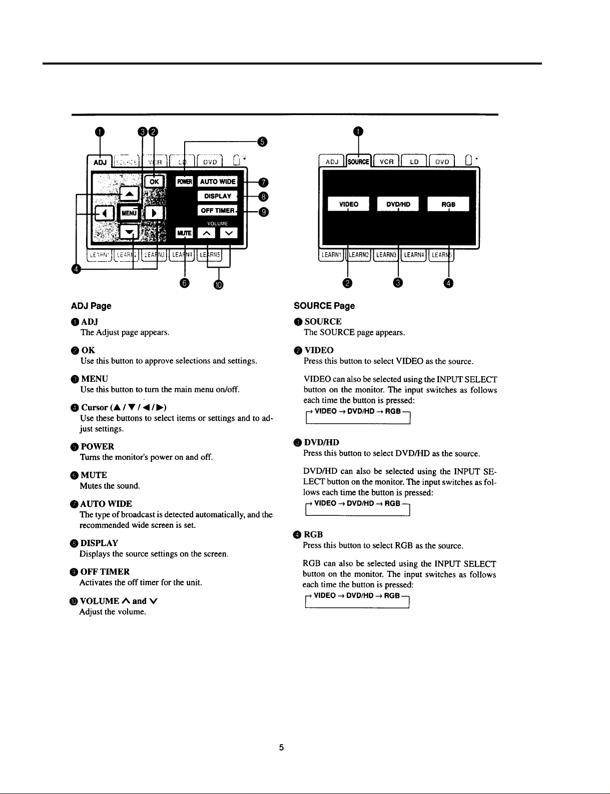
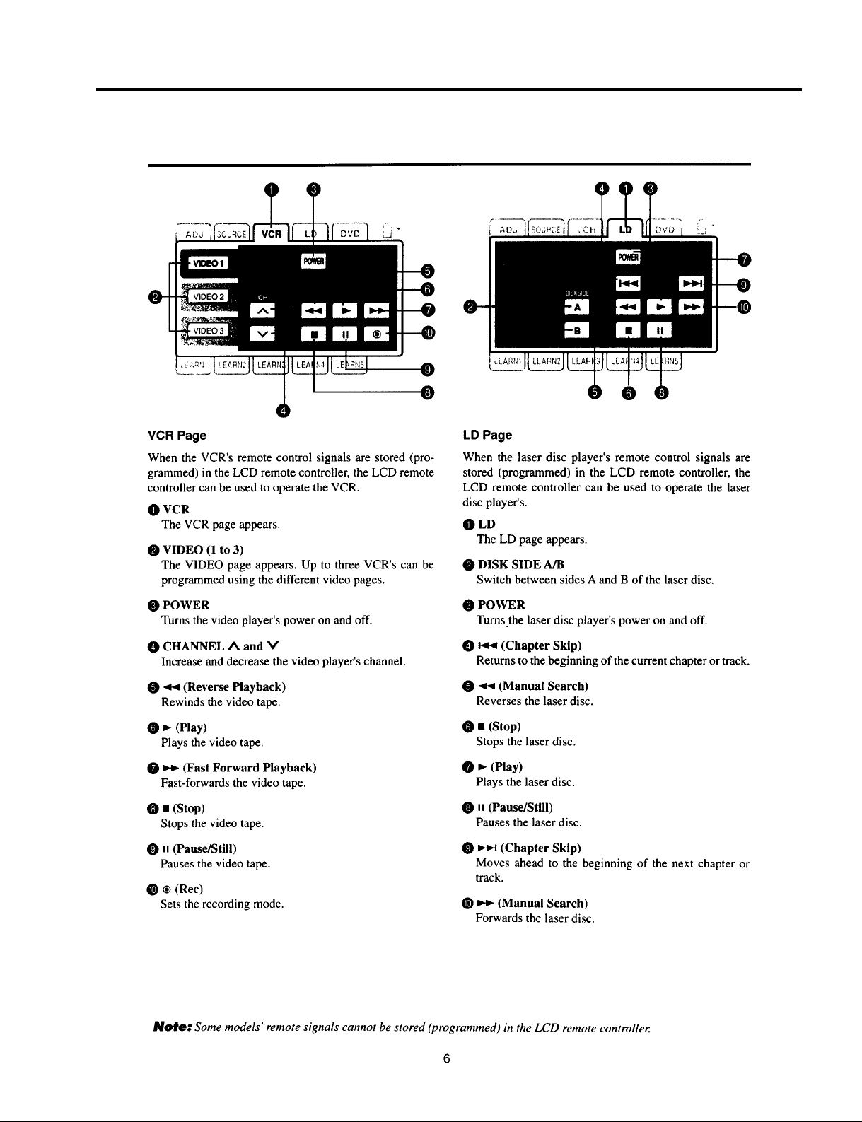
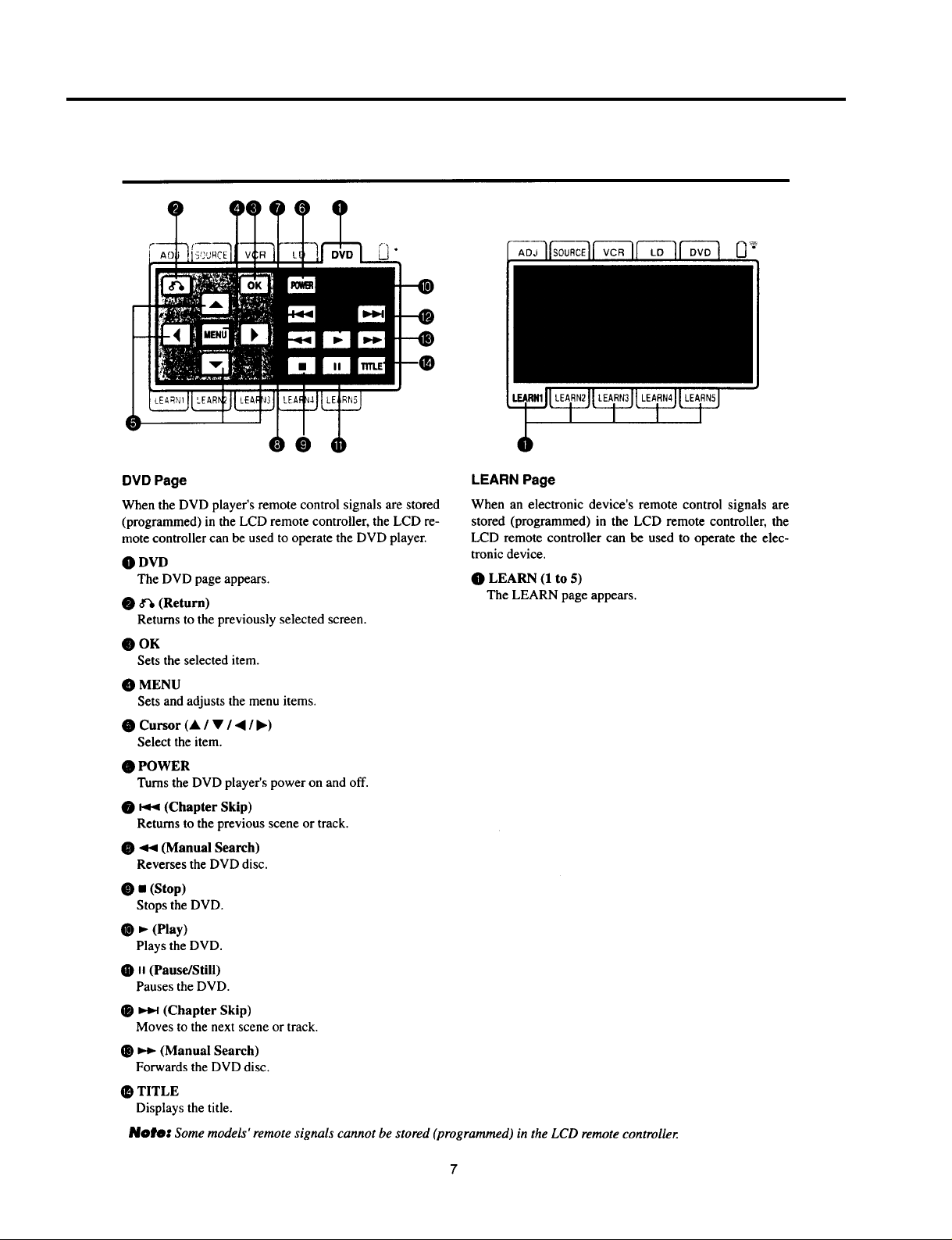
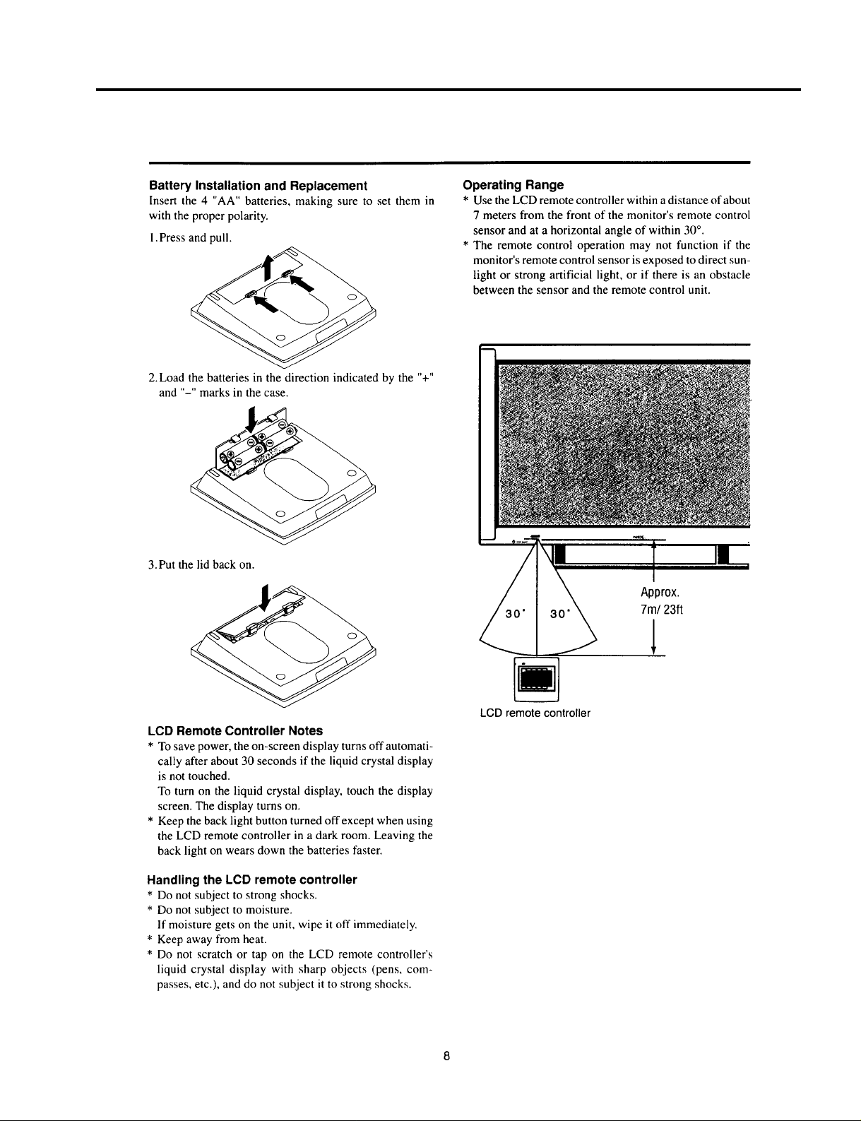
USERS MANUAL
3-1
Page 9
USERS MANUAL
3-2
Page 10
USERS MANUAL
3-3
Page 11
USERS MANUAL
3-4
Page 12
USERS MANUAL
3-5
Page 13
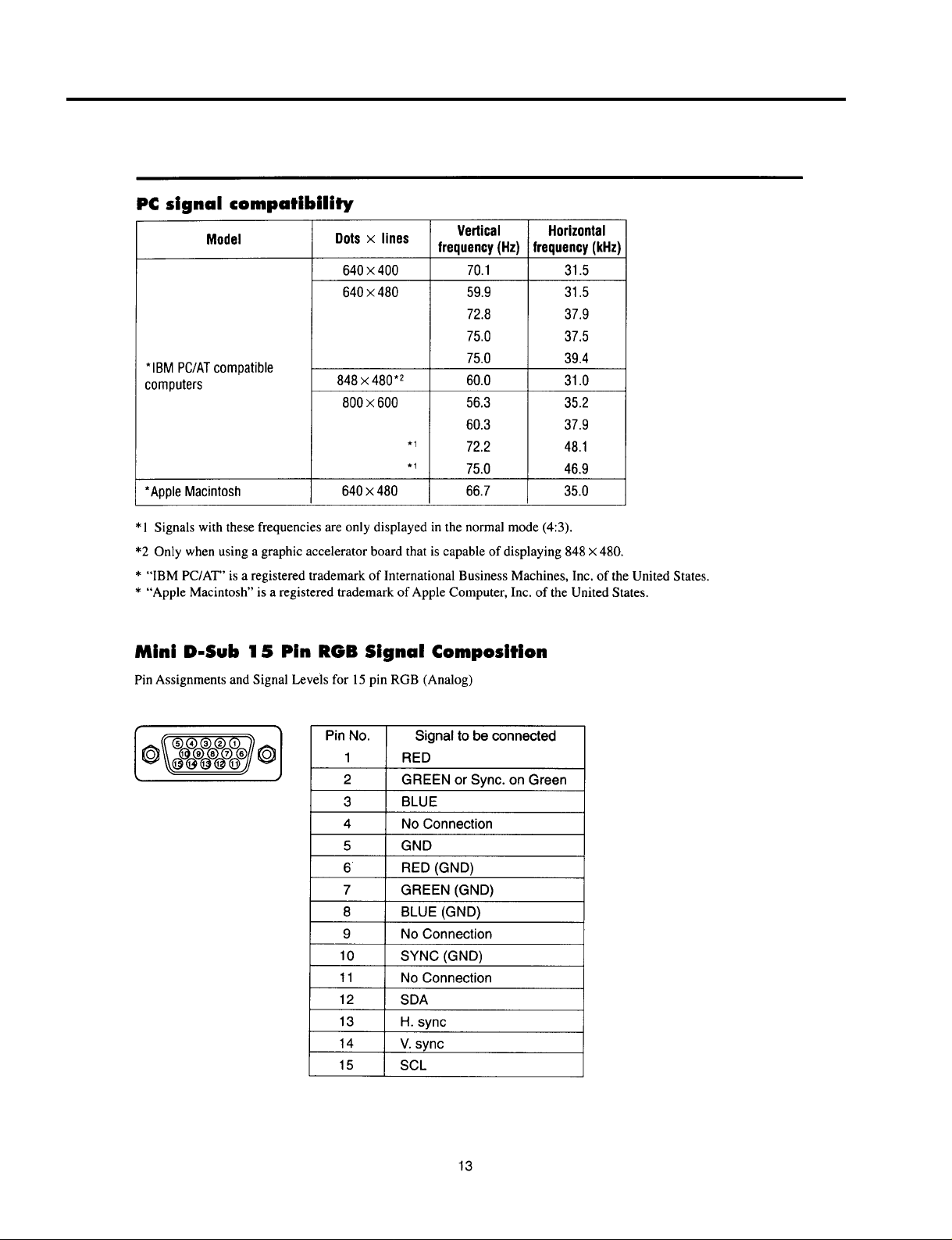
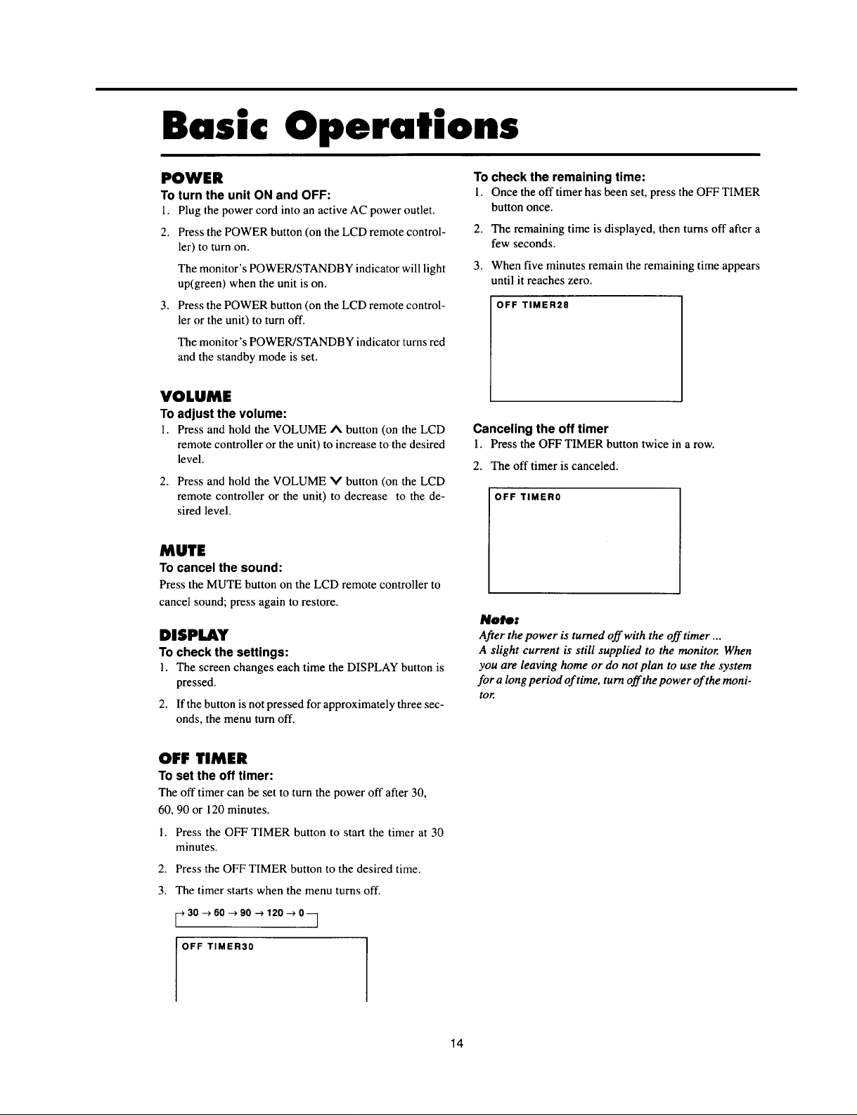
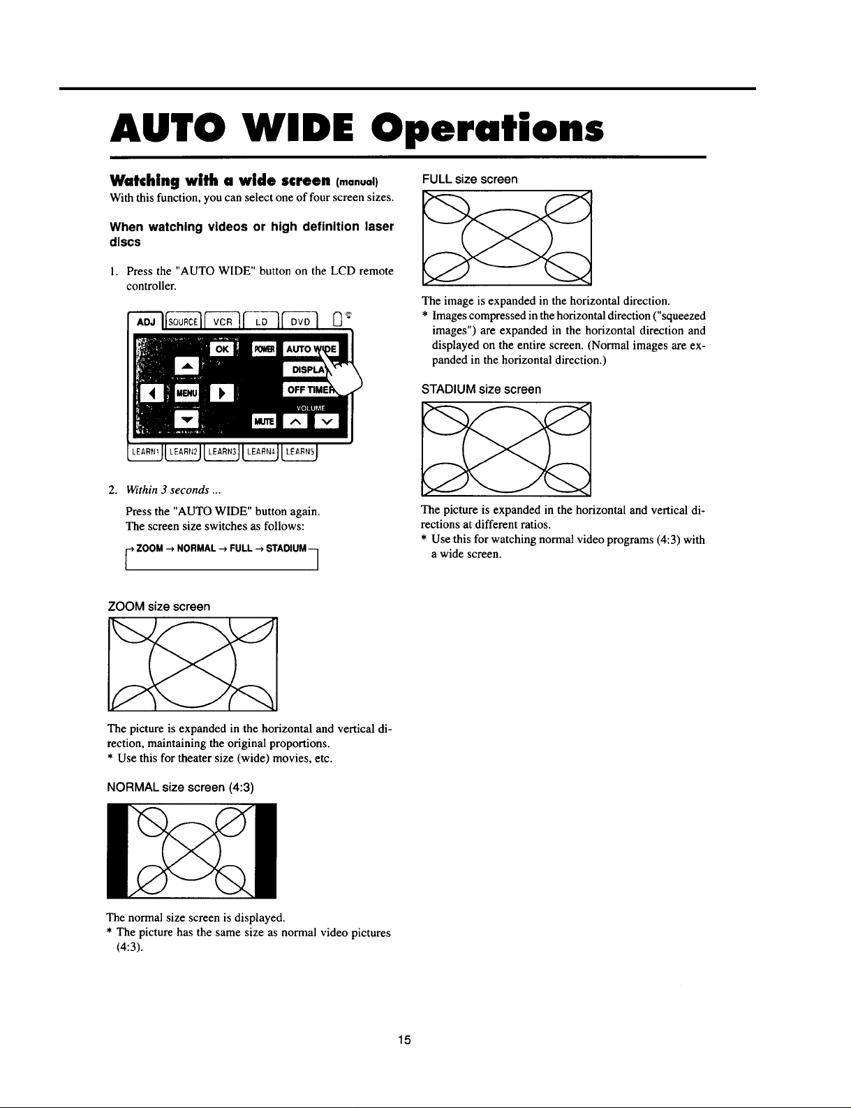
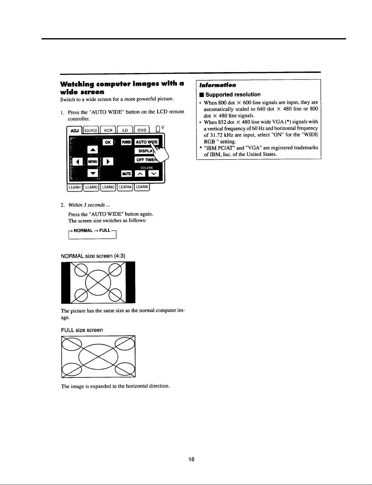
USERS MANUAL
3-6
Page 14
USERS MANUAL
3-7
Page 15
USERS MANUAL
3-8
Page 16
USERS MANUAL
3-9
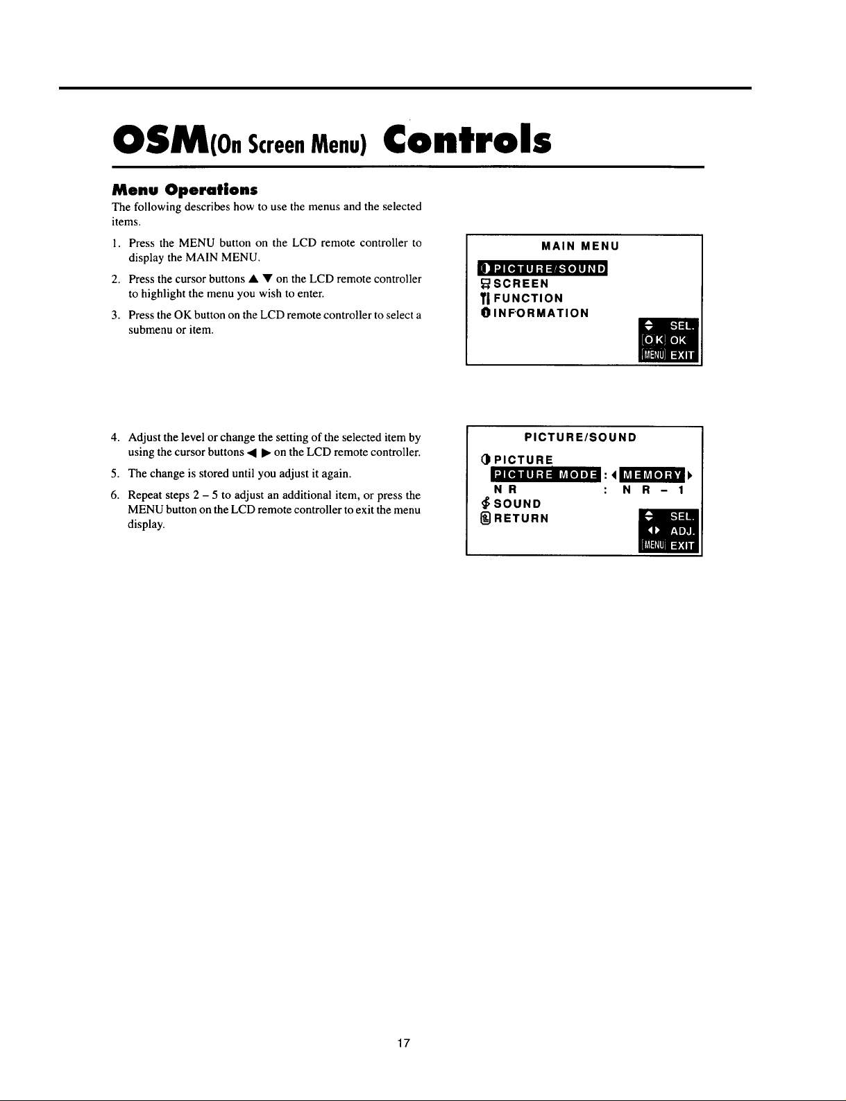
Page 17
USERS MANUAL
3-10
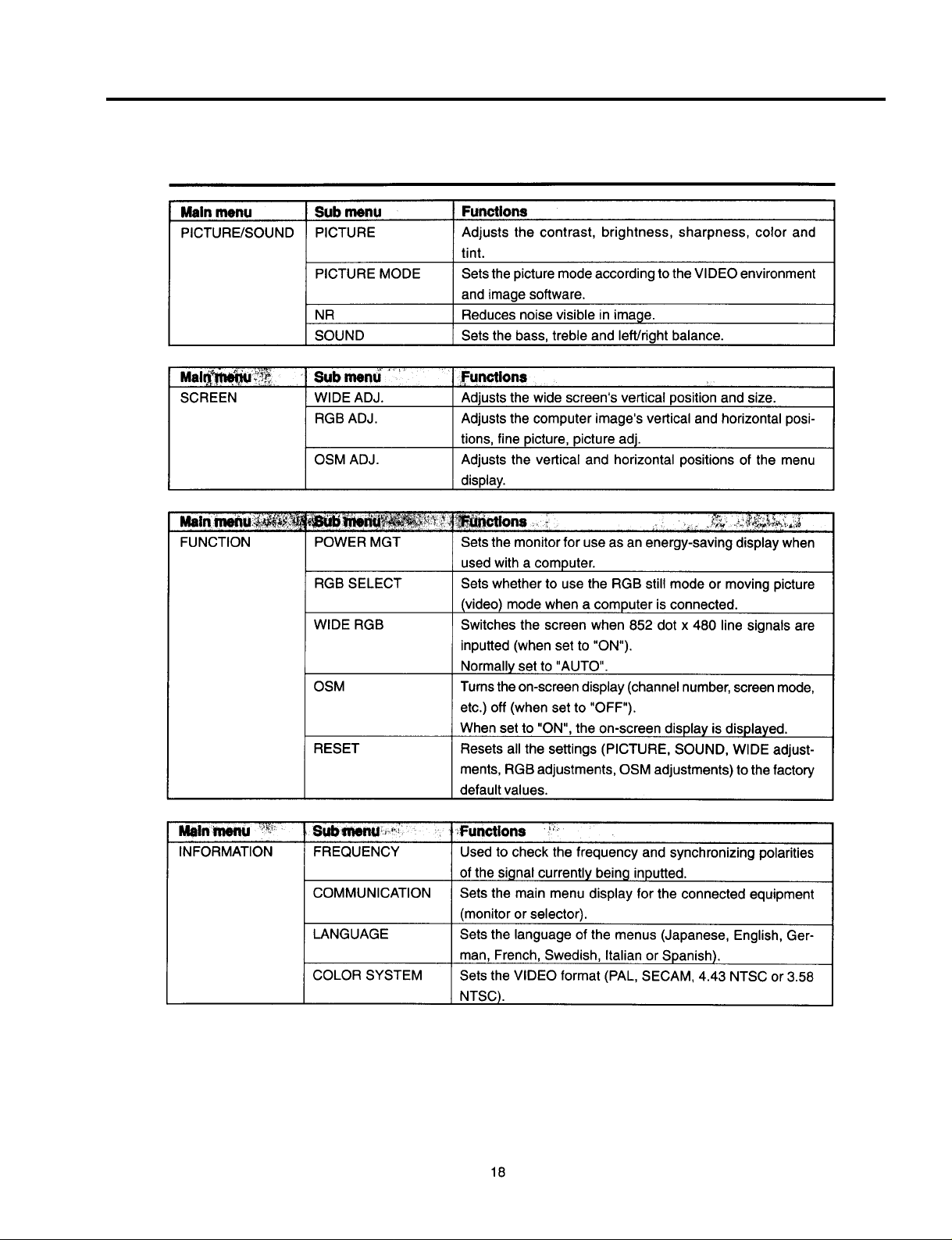
Page 18
USERS MANUAL
3-11
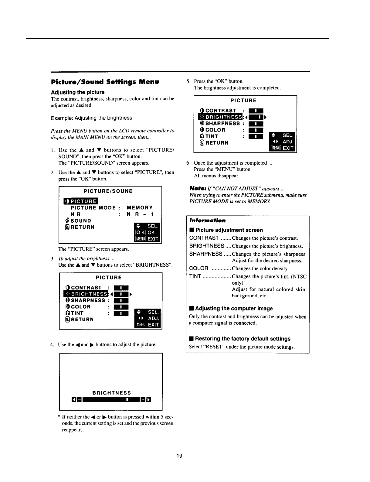
Page 19
USERS MANUAL
3-12
Page 20
USERS MANUAL
3-13
Page 21
USERS MANUAL
3-14
Page 22
USERS MANUAL
3-15
Page 23
USERS MANUAL
3-16
Page 24
USERS MANUAL
3-17
Page 25
USERS MANUAL
3-18
Page 26
USERS MANUAL
3-19
Page 27
USERS MANUAL
3-20
Page 28
USERS MANUAL
3-21
Page 29
USERS MANUAL
3-22
Page 30
USERS MANUAL
3-23
Page 31

USERS MANUAL
3-24
Page 32

USERS MANUAL
3-25
Page 33

USERS MANUAL
3-26
Page 34

USERS MANUAL
3-27
Page 35

USERS MANUAL
3-28
Page 36

USERS MANUAL
3-29
Page 37

USERS MANUAL
3-30
Page 38

USERS MANUAL
3-31
Page 39

USERS MANUAL
3-32
Page 40

USERS MANUAL
3-33
Page 41

USERS MANUAL
3-34
Page 42

USERS MANUAL
3-35
Page 43

USERS MANUAL
3-36
Page 44

USERS MANUAL
3-37
Page 45

USERS MANUAL
3-38
Page 46

USERS MANUAL
3-39
Page 47

USERS MANUAL
3-40
Page 48

USERS MANUAL
3-41
Page 49

USERS MANUAL
3-42
Page 50

USERS MANUAL
3-43
Page 51

USERS MANUAL
3-44
Page 52

USERS MANUAL
3-45
Page 53

USERS MANUAL
3-46
Page 54

USERS MANUAL
3-47
Page 55

USERS MANUAL
3-48
Page 56

USERS MANUAL
3-49
Page 57

USERS MANUAL
3-50
Page 58

USERS MANUAL
3-51
Page 59

USERS MANUAL
3-52
Page 60

USERS MANUAL
3-53
Page 61

USERS MANUAL
3-54
Page 62

USERS MANUAL
3-55
Page 63

USERS MANUAL
3-56
Page 64

USERS MANUAL
3-57
Page 65

USERS MANUAL
3-58
Page 66

USERS MANUAL
3-59
Page 67

USERS MANUAL
3-60
Page 68

USERS MANUAL
3-61
Page 69

USERS MANUAL
3-62
Page 70

USERS MANUAL
3-63
Page 71

USERS MANUAL
3-64
Page 72

USERS MANUAL
3-65
Page 73

USERS MANUAL
3-66
Page 74

USERS MANUAL
3-67
Page 75

USERS MANUAL
3-68
Page 76

USERS MANUAL
3-69
Page 77

USERS MANUAL
3-70
Page 78

USERS MANUAL
3-71
Page 79

USERS MANUAL
3-72
Page 80

USERS MANUAL
3-73
Page 81

USERS MANUAL
3-74
Page 82

USERS MANUAL
3-75
Page 83

TROUBLE SHOOTING
No energization of POWER circuit
Is POWER LED NO Is the power plug correctly NO Rearrange the power plug
lit? connected to the wall outlet? connection correctly.
YES YES
Is there AC 100V behind the NO Fuses F1 and F2 have blown
fuses F1 and F2? out.
Green flashing: To 1 (Page 4-2) If the fuses blow out again after
Red flashing: To 2 (Page 4-2) replacement, the POWER unit
Green and red flashing: To 3 (Page 4-3) is out of order.
Green lighting: To 4 (Page 4-3)
YES
Is there M+15V output at NO Disconnect the PM and PQ
Pin 1 of the PM connector? connectors from one after an-
other. If there is M+14V output,
the circuit beyond the connectors is out of order. If there is no
output, the POWER unit is out
of order.
YES
Is there +5V output at Pin
of IC6805 (ANALOG PWB)? and related circuits.
YES
Is there +5V output at Pin
of the PW connector? POWER PWB
YES
Is there +5V output at Pin
of the PW connector? IC6800 (ANALOG PWB).
YES
Failure in POWER PWB
2
NO Failure in SW2001 (CTL PWB)
5
NO Failure in +5V line as far as
3
NO Failure in peripheral area of
4-1
Page 84

TROUBLE SHOOTING
1
Is 0V observed at Pin 4 of Failure in peripheral area of IC6800
IC6800 (ANALOG PWB)?
YES
Is 0V observed at Pin 1 or
of IC6553 (ANALOG PWB)?
YES
1
0V at Pin 1: Failure in fan’s peripheral area of the set
2
0V at Pin 2: Failure in fan’s peripheral area in the POWER unit
2
Is 0V observed at Pin 57 of Failure in peripheral area of IC6800
IC6800 (ANALOG PWB)?
2
NO
NO
NO
Failure peripheral area of IC6553
YES
Is 0V observed at Pin 5 of Failure in peripheral area of IC6808
IC6808 (ANALOG PWB)?
YES
Failure in TH1 of the POWER
unit and peripheral circuits
NO
4-2
Page 85

TROUBLE SHOOTING
3
Is 0V observed at Pin $ of Failure in peripheral area of IC6800
IC6800 (ANALOG PWB)?
YES
Failure in peripheral area of
MODULE circuit
4
Is “H” maintained at Pins 2 and Failure in peripheral area of IC6800
3
of the PM connector?
YES
Is “H” maintained at Pin 7 of Failure in peripheral area of MODULE
the PH connector?
YES
Is power supply available when Confirm that the power supply is a vailable by disconnecting
SW1 (POWER unit: HV system the connectors of PV, PQ, PN, PA from one after another
is OFF) is turned OFF? (others keptconnected). If available, circuit of the disconn-
YES
NO
NO
NO
NO
ected connector is out of order. If not available, the POWER
unit is out of order.
Failure in peripheral area of the
HV system in MODULE and
POWER unit.
4-3
Page 86

TROUBLE SHOOTING
No display (no video screen display)
Enter a color bar signal input.
Is there on-screen display NO Refer to Fault Analysis for
of VIDEO? ANALOG PWB and thereafter.
YES
Is there a video signal at NO
TP1001? is there a video signal at the source.
YES YES
With the YC connector NO Failure in peripheral area of
disconnected, is there a IC1001
video signal at TP1025?
YES
Is there a video signal at NO Is there a rectangular waveform NO Failure in peripheral
Pin 2 of the VD connector signal of 5Vp-p at pins 2 and 3 area of IC6800
in VIDEO PWB? of the JC connector?
YES YES
Refer to Fault Analysis for
ANALOG PWB and thereafter.
With the signal line disconnected,
signal line terminal?
Failure in peripheral area of
IC1001
To 5 (Page 4-5)
NO Failure in signal
4-4
Page 87

5
Signal Y input is available NO Failure in peripheral area of
at Pin 53 of IC5008. IC5008.
YES
Signal Y output is available NO Failure in peripheral area of
from Pin 4 of IC5008. IC5012 ~ IC5017.
YES
Signal Y (or VIDEO) input NO Failure in peripheral area of
is available at Pin 15 of IC5008.
IC5008.
YES
Signal Y (or VIDEO) output NO Failure in Q5011 and Q5037~
is available at Pin 6 of Q5039.
IC5005.
TROUBLE SHOOTING
YES
There is a signal input at IC5006: NO Failure in peripheral area of
Signal Y at Pin 14 for NTSC, Signal Y at IC5005.
Pin 16 for PAL, Signal VIDEO at Pin 1 for
SECAM, and Signal Y at Pin 9 for S-input.
YES
Abnormality occurring with SECAM/S input
is due to failure in V-I/O board. Abnormality
occurring with NTSC/PAL is due to failure in
YC separator circuit.
4-5
Page 88

TROUBLE SHOOTING
No display (no HD/DVD screen display)
Enter a color bar signal
input.
Is there on-screen display NO Refer to Fault Analysis for
of “HD” or “DVD”? ANALOG PWB and thereafter.
YES
Is there a video signal at NO With the signal line disconnec- NO Failure in signal
TP1004? ted is there a video signal at source.
the signal line terminal?
YES YES
Failure in the signal line of
IC6110 or before it.
Refer to Fault Analysis
for ANALOG PWB and
thereafter.
4-6
Page 89

TROUBLE SHOOTING
No display (no RGB/PC screen display)
Enter a VGA or SVGA
color bar signal input.
Is there on-screen display NO Refer to Fault Analysis for
of “PC”? ANALOG PWB and thereafter.
YES
Is LED lit in green ? NO Is there horizontal sync at NO Failure in the signal
(Not in power management) Pin 13 of M1006, or vertical line.
sync at Pin 14?
YES YES
Is there horizontal sync at NO Failure in the VI/O
Pin 8 of ANALOG PWB “PC” sync system (Q1050
connector, or vertical sync at and peripheral area
Pin 10? of IC1006).
YES
Is there horizontal sync at Pin Failure in the ANALOG
89 of IC6800, or vertical sync PWB sync system.
at Pin 19?
YES
Failure in the peripheral area
of IC6800.
Is there a video signal at NO With the signal line disconnected, NO Failure in the signal
TP1007, TP1008, and is there a video signal at the line.
TP1009? signal line terminal?
YES YES
Failure in the signal line of
IC6110 or before it.
Refer to Fault Analysis for
ANALOG PWB and
thereafter.
NO
4-7
Page 90

TROUBLE SHOOTING
No display (fault analysis for ANALOG PWB and thereafter)
Is there a video signal at TP6139, NO Failure in ANALOG PWB (peripheral area of the signal line
TP6140, and TP6141? before AD converter)
YES
Is there a signal of 5Vp-p at Pins 1 NO Failure in ANALOG PWB (signal circuit or sync system circuit
~ 47 of the AD connector of AD converter and thereafter, or peripheral area of IC6800).
(odd-numbers only)?
YES
Is there a clock signal at Pin 49 NO Failuure in ANALOG PWB (sync system circuit or peripheral
of the AD connector? area of IC6800).
YES
Is there a signal of 5Vp-p at NO Failure in ANALOG PWB (sync system circuit or peripheral
Pin 52 of the AD connector area of IC6800).
(H-SYNC), Pin 53 (V-SYNC),
or Pin 76 (V period)?
YES
NO
Is normal display available after Failure in the AD cable.
replacement of AD cable?
YES
NO
Is normal display available after Failure in ANALOG PWB
replacement of ANALOG PWB?
YES
NO
Are the PD and PH connectors Make correct connections.
correctly connected?
YES
NO
Are there normal outputs of 180V , Refer to No energization of POWER circuit.
80V , and D+5V in the POWER unit?
YES
Failure in the plasma display
module.
4-8
Page 91

TROUBLE SHOOTING
No video in NTSC Mode
YES
Signal Y is available at Failure in Q9001 ~ Q9003.
TP9003.
NO
There is a VIDEO signal YES There is an FSC signal NO Failure in Q9010/
at TP9007. (3.5MHz sine wave) at TP9008. Q9015/Q9016/Q9023.
NO YES
6
There is a VIDEO Failure in There is an 8FSC signal NO There is a vertical
signal at Pin 1 of Q9009/9011/ (28.63MHz sine wave) at TP9013. sync signal at Pin 1 of
the POYC connector.
NO YES
Failure in the V-I/O board. There is a horizontal sync signal NO
YES
Q9012/ Q901. IC9004, and also a
composite sync signal
at Oin 2.
at TP901 1.
YES
There is a vertical sync signal NO
at TP9012.
YES YES
Failure in the peripheral area Failure in IC9004.
of IC9086.
NO
Failure in Q9013/
Q9017/ Q9018 or in
the pre-stage.
4-9
Page 92

TROUBLE SHOOTING
No PAL Reproduction
YES
Signal Y is available at Failure in Q5007/Q5046/IC5015.
TP5004.
NO
There is a VIDEO signal YES There in an FSC signal (3.58MHz NO Failure in the peripheral
at TP5030. sine wave) at Pin 19 of IC5007. area of Q5023.
NO YES
7
There is a VIDEO Failure in Pin 10 of IC5007 is led to LO.
signal at Pin 1 of Q5036/Q5004
the POYC connector.
NO YES NO
Failure in the V-I/O board. Failure in the peripheral area Failure in the peripheral
YES
~Q5006.
of IC5007 areaof Q5035.
4-10
Page 93

No color Reproduction
TROUBLE SHOOTING
RGB signal is available at Failure in ANALOG PWB
Pins 1, 3, 5 of the POVD
connector.
NO
R-Y/B-Y signal is available Failure in the peripheral area of IC5008.
at Pins 51 and 52 of IC5008.
NO
R-Y/B-Y signal is available Failure in the peripheral area of IC5012.
at Pins 7 and 8 of IC5012.
NO
R-Y/B-Y signal is available Failure in the peripheral area of IC5009.
at Pins 26 and 27 of IC5009.
NO
Failure in the SECAM demodulation system for SECAM.
Failure in the peripheral area of IC5010 (SECAM demodulation system)
if there is R-Y/B-Y signal is available at Pins 12/13 of IC5010. If there is no
such signal, it is then a failure in the Y/C separator circuit (or IC5008).
YES
YES
YES
YES
4-11
Page 94

TROUBLE SHOOTING
No NTSC color generation
Signal C is available at Pin 13 of IC5008. Failure in the peripheral area of IC5008.
NO
Signal C is available at Pin 14 of IC5006. Failure in the peripheral area of IC5006.
NO
Signal C is available at TP9004. Failure in Q9005 ~ Q9008.
NO
To Step 6 (Page 4-9)
YES
YES
YES
No PAL color generation
Signal C is available at Pin 13 of IC5008. Failure in the peripheral area of IC5008.
NO
YES
Signal C is available at Pin 16 of IC5006. Failure in the peripheral area of IC5006.
NO
Signal C is available at TP9005. Failure in Q5009/ Q5047/ IC5016.
NO
To Step 7 (Page 4-10)
YES
YES
No SECAM color generation
Signal C is available at TP5017. Failure in the peripheral area of IC5006.
NO
Failure in the peripheral area of IC5017.
YES
4-12
Page 95

Abnormality in the sync system
Enter a color bar signal
input.
TROUBLE SHOOTING
Is it a VIDEO input? Is it an HD/DVD input?
YES YES
Is there a video signal at NO Is there a video signal NO Is threr a sync signal
TP1025? at Pin 2 of the “HD” at Pin 8 and 10 of
YES YES YES
Is there a sync signal at VIDEO PWB defective.
Pins 6 and 8 of the “VD”
connector?
Are there a clock signal
synchronized with the input NO ANALOG PWB
signal, a horizontal sync defective.
signal, and a vertical sync
signal respectively at Pins
49, 51, and 53 of the “AD”
connector?
NO NO
connector? the “PC” connector?
NO
NO
VI/O PWB
defective.
YES
NO
Is normal display available Failure in the AD cable.
after replacement of AD
cable?
NO
Is normal display available NO Failure in ANALOG
after replacement of PWB
ANALOG PWB?
NO
Failure in the plasma
display module.
4-13
Page 96

TROUBLE SHOOTING
No audio signal from speaker output
Audio signal is available Voltage is 3V or about TP3003. Failure in IC3003.
at POSR/POSL.
NO
Audio signal is available YES
at TP3004/3005.
NO 8 NO
Audio signal is available Failure in Q3003 and Q3004.
at Pins 10/21 of IC3001.
NO YES
Audio signal is available Failure in the peripheral area
at TP3001/3002 of IC3002.
NO YES
Audio signal is available Failure in the peripheral area
at TP4002/4003. of IC3001.
NO YES
YES YES
Audio signal is available Failure in the peripheral area
at Pins 1/3/4/6/8/10 of of IC4002.
IC4001.
NO YES
Check each PHONO Failure in the peripheral area
pin input. of IC4001.
4-14
Page 97

No audio output from AUDIO OUT
TROUBLE SHOOTING
Audio signal is available at TP4006/4007. Check the Super-woofer side.
NO
Audio signal is available at Pins 1/3 of the Faiurte in IC4003
POMS connector.
NO
To Step 8 (Page 4-14)
YES
YES
4-15
Page 98

METHOD OF ADJUSTMENTS
I. Application
This specification covers the method of adjustments for the color plasma display “PX-42M2A/G” for domestic users.
II. Adjustment items
<Analog Block>
1. Setting and confirmation before adjustments
2. Adjustment of µPC1885
3. Adjustment of image level (M52327SP)
3-0. Lowpass Filter Level Adjustment
3-1. Adjustment of HD/DVD level
3-2. Adjustment of video level
3-3. Adjustment of PC/RGB level
3-4. Adjustment of sub-brightness
3-5. Adjustment of sub-contrast
4. Setting for APL control
5. Unit inspection for ANALOG PWB and VIDEO PWB
5-1. Setting of inverse gamma
5-2. Confirmation of video siganls
5-3. Confirmation of video control siganls
5-4. Confirmation of HD/DVD signal processing
5-5. Confirmation of HD/DVD signal mode
5-6. Confirmation of PC 400-line mode
5-7. Confirmation of PC VGA mode
5-8. Confirmation of PC SVGA mode
5-9. Confirmation of PC MAC signal mode
5-10. Confirmation of APL correction data
5-11. Detection of fan stop
5-12. Confirmation of short-circuit test panel crack detection signal
6 . Data writing for plug and play
7 . Setting and confirmation before shutdown
<Audio Block>
1. Confirmation before adjustments
2. Adjustment of audio output level
3. Adjustment of audio balance
<Set Adjustment>
1. Adjustment of screen position and phase
1-1. Adjustment of video screen position
1-2. Adjustment of HD/DVD screen position
1-3. Adjustment of PC/RGB screen position
1-4. Tuner Selector Adjustment
2. Adjustment of -180V and +80V
3. Adjustment of +5V
5-1
Page 99

<Protector Operation>
1. Confirmation of overcurrent protector
2. Confirmation of reduced-voltage protector
<Printed Wiring Board Layout>
1. ANALOG board (PWC-4214)
2. VIDEO board (PWC-4213)
3. AUDIO board (PWC-4216)
4. Top view of power unit
<Signal Waveforms for Adjustment>
1. Video input
2. HD/DVD input
3. RGB input
METHOD OF ADJUSTMENTS
<Contents of Adjustment after changing PWB>
1. After changing ANALOG PWB (PWC-4214):
Perform the steps as described in the “Adjustment of video level”, item 3-2 (P5-6~P5-7) of <ANALOG PWB>
and the “Adjustment of screen and phase”, item 1 (P5-14~P5-16) of <Set Adjustment>.
2. After changing VIDEO PWB (PWC-4213A):
Perform the steps described in “Adjustment of video level”, item 3-2 (P5-6~P5-7) of <ANALOG PWB)> and the
“Adjustment of video screen position”, item 1-1 (P5-14) of <Set Adjustment>.
3. After changing the Power Unit:
Perform the steps described in the “Adjustment of –180V and +180V”, item 2 (P5-16) of <Set Adjustment>. The
appropriate voltage is indicated in the label on the Module.
Also perform the steps described in the “Adjustment of +5V”, item 3 (P5-16) of <Set Adjustment>.
Replacing another PWB does not require further adjustment unless abnormal conditions are encountered.
5-2
Page 100

METHOD OF ADJUSTMENTS
<ANALOG PWB>
Adjustment for the ANALOG PWB, PWC-4214, should be performed in a pair with the VIDEO PWB, PWC-4213A.
The ANALOG PWB shall be adjusted if the ANALOG PWB or VIDEO PWB has been replaced.
1. Setting and confirmation before adjustments
1-1 Insert a short-plug on the opposite side of “▲ silk” in JP6550. However, this should be done only for unit
operation of the board only. After adjustment of the board, return the short-plug to the side of “▲ silk.”
Confirm that a short-plug is inserted on the opposite side of Pin 3 “▲ silk” in JP6600. (Selection of microcomputer side)
Confirm that a short-plug is inserted on the side of Pin 1 “▲ silk” in JP6551. (Selection of microcomputer
side)
1-2 Confirm that the 5ns delay line (A T -10) is set in DL6501 and another 5ns delay line (AT-05) is set in DL6502,
and that short-pins are inserted in DL6500, DL6503, and DL6506.
1-3 Move the dip switches SW6500 and SW6501 to the “OFF” side. Confirm that the dip switches SW6550 and
SW6603 are set on the “ON” side.
1-4 Set the rotary switch W6602 in the “F” position. (Set at inverse gamma correction OFF)
1-5 Confirm that each terminal voltage specified below is kept within the standard range at an ordinary tem-
perature.
Board name Terminal No Signal name Standard voltage value
ANALOG PWC-4214 PM
VIDEO PWC-4213A PV
VI/O PWC-4213B PQ
1
PM
5
PM
!
PN
1
PN
6
IC6073
IC6072
IC6000
IC6301
IC6001
IC6300
IC6003
IC6805
PV
TP5001 VIDEO + 9V 9 ± 0.27V
TP5002 SW + 9V 9 ± 0.27V
TP5003 VIDEO + 5V 5 ± 0.15V
TP5011 VIDEO + 12V 12± 0.15V
PQ
IC1008
IC1009
3
1
3
3
3
3
3
2
1
3
1
4
4
3
M + 14V 14V ± 5%
D + 12V 5 ± 5%
F + 12V 12 ± 10%
A + 14V 14V ± 5%
A + 7V 6.5~9.0V
VDD3 3.14~3.46V
CDDVCO 5 ± 0.15V
A1 + 12V 12 ± 0.15V
A0 + 12V 12 ± 0.15V
A1 + 5V 5 ± 0.15V
A1 + 5V 5 ± 0.15V
M1 + 12V 12 ± 0.35V
M + 5V 5 ± 0.15V
A + 14V 14 ± 5%
A + 7V 6.5~9.0V
M + 14V 14 ± 5%
MA + 7V 6.5~9.0V
AMP + 5V 5 ± 0.15V
RGB + 5V 5 ± 0.12V
5-3
 Loading...